Embed Size (px)
Citation preview
SQKKIAGGr:Er=I-E~1.
~rtll_~p-~~r-6ir:-i-,--TLi-.i\..--r'"£i.~Ii.._~~~~~¡.i.
~.~It ______..~~ .... "__~~.'._._'_'._'__"."'_
SET5FSET5FSSET5W
SET5WSElectronic Total Station
OPERATOR'S MANUAL
eJ1
:i1r;9EJ
99Ej
EJE1
E~1
E;l
E~I
Eì
E~i~
~l
~
. (English)
. (Deutsch)
. (Français)
. (Italiano)
. (Nederlands)
. (Español)
. (Português)
. (Svensk)
. (Suomi)
. (Norsk)
. (Dansk)
. (EÂÀ:rivtlm)
~ Ni-Cd
CONTAINS NICKEL-CADMIUM BATTERY.MUST BE RECYCLED OR DISPOSED OF PROPERLY.
MIT NiCd AKKU. EFORDERT RECYCLING ODERFACHGERECHTE ENTSORGUNG.
CONTIENT UNE BATTERIE AU CADMIUM NICKEL.DOlT ÊTRE RECYCLÉE OU DONNÉE A UN ORGANISMEDE RETRAITEMENT.
CONTIENE NiCd BATTERIA. DEVE OUINDI ESSERERICICLATA 0 ELiMINATA IN MODO APPROPRIATO.
BEVAT EEN NiCd BATTERIJ. DIENT GERECYCLEERD TEWORDEN OF OP EEN CORRECTE MANIER VERNIETIGDTE WORDEN.
CONTIENE UNA NiCd BATERíA. DEBE RECICLARSE 0ELiMINARSE ADECUADAMENTE.
CONTEM BATERIA DE NíOUEL CÁDMIO. DEVERÁ SERRECICLADA OU DECARTADA CONVENIENTEMENTE.
INNEHALLER NiCd BATTERI. BÖR ATERVINNAS ELLERFÖRSTÖRAS PA ETT SÄKERT SÄTT.
SISÄL TÄÄ NIKKELI-KADMIUM AKUN.HÄVITETTÄESSÄ KÄSITEL TÄVÄ ONGELMAJÄTTEENÄ.
NiCd BATTERIER MA RESIRKULERES ELLER KASTES PAEN FORSVARLIG MATE.
INDEHOLDER NiCd BATTERI. SKAL GENVINDES ELLERKASSERES PA FO,RSVARLIG MADE.
IlEPIEXEI MIlA TAPIA NIKEAlOY-KA¿\MIOY.IlPEIlEI NA ANAKYKAQNETAI H NA KA TALTPEl1ETAI METON KAT AMHAO TPono.
For U.S.A. ATTENTION:The product that you have purchased contains a rechargeable battery.The battery is recyclable. At the end of it's useful life, under various state andlocal laws, it may be illegal to dispose of this battery into the municipal wastestream. Check with your local solid waste officials for details in your area forrecycling options or proper disposaL. Use the standard battery charger.
Die Schweiz: Nach Gebrauch der Verkaufsstelle zurückgeben.La Suisse: Après usage à rapporter au point de vente.Swizzera: Ritornare la pila usate al negozio.
-~1~rir~~~-' r-i
~-~
~_-d___
'f-riJ -
~~i
~~-¡
~~~
~~-, .I' -.~-~
:d1
s-a
~~~.~"'.. -' :r .-,. ~
~~
SET5FSET5FSSET5W
SET5WSElectronic Total Station
OPERATOR'S MANUAL
. Thank you for selecting the SET5F/SET5FS/SET5W/SET5WS Electronic Total Station.
· Before using the instrument, please read this operator'smanuaL.
. Verify that all equipment is included by referring to"STANDARD EQUIPMENT", P168.
· The specifications and general appearance of theinstrument may be altered at any time and may differ-fromthose appearing in brochures and this manuaL.
. The picture on the cove!.an~.-~ustra~ions are of the SET5W
;,
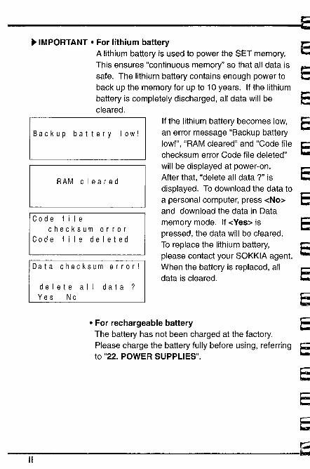
~ IMPORTANT · For lithium batteryA lithium battery is used to power the SET memory.This ensures "continuous memory" so that all data issafe. The lithium battery contains enough power toback up the memory for up to 10 years. If the lithiumbattery is completely discharged, all data will becleared.
Backup battery low!If the lithium battery becomes low,an error message "Backup batterylow!", "RAM cleared" and "Code filechecksum error Code file deleted"will be displayed at power-on.After that, "delete all data ?" isdisplayed. To download the data toa personal computer, press -cNo~
and download the data in Datamemory mode. If -cYes~ ispressed, the data will be cleared.To replace the lithium battery,please contact your SOKKIA agent.When the battery is replaced, alldata is cleared.
RAM cleared
Code filechecksum error
Code file deleted
Data checksum error!
delete all data?Yes No
· For rechargeable batteryThe battery has not been charged at the factory.Please charge the battery fully before using, referringto "22. POWER SUPPLIES".
ii
j
~e1
E,l:1
Cìi:'_~¡¡r
i:'~,
~,L~
~r
~
~
~~T"iL
~L~~
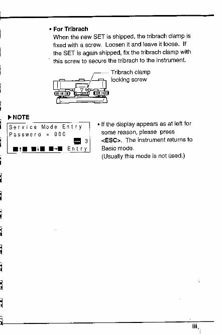
· For TribrachWhen the new SET is shipped, the tribrach clamp isfixed with a screw. Loosen it and leave it loose. Ifthe SET is again shipped, fix the tribrach clamp withthis screw to secure the tribrach to the instrument.
~ NOTE
Service Mode EntryPassword = 000
= 3.t. .l. .~. Ent ry
. If the display appears as at left forsome reason, please press-cESC~. The instrument returns toBasic mode.
(Usually this mode is not úsed.)
'¡
~~t-tl
~~::'J~
~~~
~~ iii,
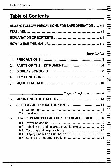
Table of Contents
Table of Contents
ALWAYS FOLLOW PRECAUTIONS FOR SAFE OPERATION ...... viii
FEATURES ........................................................................................ xii
EXPLANATION OF SOFTKEYS ............................................ xiii
HOW TO USE THIS MANUAL .................................................. xiv
Introduction
1. PRECAUTIONS .................................................................3
2. PARTS OF THE INSTRUMENT .................................... 4
3. DISPLAY SYMBOLS .........................................................6
4. KEY FUNCTIONS .............................................................. 7
5. MODE DIAGRAM ............................................................ 10
Preparation for measurement
6. MOUNTING THE BATTERy.................................. 13
7. SETTING UP THE INSTRUMENT ...............................147.1 Centering ....................................................................... 147.2 Levelling ......................................................................... 16
8. POWER ON AND PREPARATION FOR MEASUREMENT .... 20
8.1 Power on and off ........................................................... 208.2 Indexing the vertical and horizontal circles ..................... 228.3 Focusing and target sighting .......................................... 238.4 Display and reticle illumination ....................................... 258.5 Setting the instrument options ...................................... 26
iv
EE"
1
jE"
EJ
EJ1
Ec~
EJ, 1
~
~i
~ Table of Contents
~If 9.~
Table of Contents
Measurement
10.
ANG LEM EASU R EM E NT ........................................... 339.1 Measure the horizontal angle between 2 points ............. 349.2 Set Horizontal circle to a required value ......................... 359.3 Horizontal angle display selection .................................. 369.4 Horizontal angle repetition .............................................. 379.5 Slope in % ....................................................................... 39
DISTANCE MEASUREMENT ........................................ 4010.1 Atmospheric correction ...................................................4110.2 Return signal checking ................................................... 4410.3 Distance and angle measurement .................................4510.4 Tracking measurement ...................................................4710.5 Review of measured data .............................................. 48
11. COORDINATE MEASUREMENT .............................. 4911.1 Instrument station coordinates setting ............................ 5011.2 Target height and instrument height setting .................... 5211.3 Azimuth angle setting ..................................................... 5311.4 3-Dimensional coordinate measurement ........................ 56
Advanced measurement functions
12. RESECTION MEASUREMENT ............................... 61
13. MISSING LINE MEASUREMENT ................................ 6613.1 Measuring the distance between 2 or more points .........6713.2 Changing the starting position ....................................... 69
14. SETTING-OUT MEASUREMENT ............................. 7014.1 Distance setting-out measurement ................................. 7114.2 Coordinates setting-out measurement........................... 7414.3 REM setting-out measurement ...................................... 77
15. OFFSET MEASUREMENT ......................................7815.1 Distance offset ..............................................................7915.2 Angle offset .................................................................. 81
16. REM MEASUREMENT ..............................................83
v
Table of Contents
Table of ContentsUsing Data memory function
17. DATA MEMORY FUNCTION ......................................8917.1 Changing the instrument options .................................... 9117.2 Job selecting ...................................................................9217.3 Instrument station data and Measured data recording ... 9317.4 Instrument station data and Measured data
reviewing / deleting / outputting .................................. 10117.5 Feature code inputting / deleting / reviewing ................ 10417.6 Coordinate data inputting / deleting / reviewing ............ 107
Troubleshooting
18. ERROR MESSAGES ............................................ 113
19. CHECKS AND ADJUSTMENTS ............................ 11619.1 Plate level ......................................................................11619.2 Circular level................................................................11819.3 Tilt sensor ..................................................................... 11919.4 Reticle .......................................................................... 12319.5 Optical plummet ........................................................... 12819.6 Distance measurement check flow chart ...................... 13019.7 Additive distance constant ........................................... 131
vi ~
~~~--¡;~
~~~~..-~~~~liiir-~1\'i-
~!"::._
~;..~~
" ;;
::.:l~
~__ ;;". ~Ii
~~~--'""
Table of Contents
Table of ContentsMeasurement options selection
20. CHANGING INSTRUMENT PARAMETERS ................135
21. CHANGING LOCATION OF FUNCTIONS FOR KEYS... 14421.1 Key function allocating ................................................ 14621.2 Registered location recalling ........................................ 151
22. POWER SUPPLIES ............................................... 153
23. REFLECTING PRISMS AND ACCESSORIES ............156
Appendices
Appendix 1: Manually indexing the vertical circle by faceleft, face right measurements ................... 161
Appendix 2: For distance measurement of the highestaccuracy........................................................ 162
Appendix 3: Earth-curvature and refraction correction. 164
Appendix 4: Standard accessories .............................. 165
Appendix 5: Optional accessories .............................. 166
STANDARD EQUIPMENT ............................................. 168
MAINTENANCE .................... ...... .......................................... 169
SPECIFICATIONS .......................... ......... ................. ............ 170
ATMOSPHERIC CORRECTION CHART .......................... 174
REGU LATIONS ...................... ................ .................... .......... 175
vii,
ALWAYS FOLLOW PRECAUTIONS FOR SAFE OPERATION
I ALWAYS FOllOW PRECAUTIONS FOR SAFE OPERATION
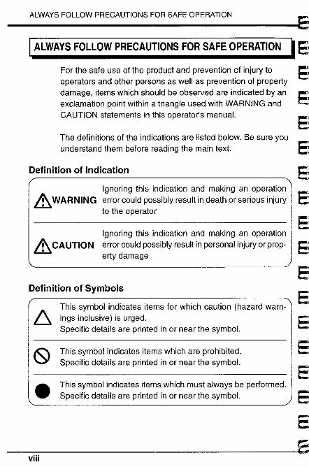
For the safe use of the product and prevention of injury tooperators and other persons as well as prevention of propertydamage, items which should be observed are indicated by anexclamation point within a triangle used with WARNING andCAUTION statements in this operator's manuaL.
The definitions of the indications are listed below. Be sure youunderstand them before reading the main text.
Definition of Indication
Ignoring this indication and making an operation& WARNING error could possibly result in death or serious injury
to the operator
Ignoring this indication and making an operation
& CAUTION error could possibly result in personal injury or prop-erty damage
Definition of Symbols
6 This symbol indicates items for which caution (hazard warn-ings inclusive) is urged.Specific details are printed in or near the symboL.
(9 This symbol indicates items which are prohibited.Specific details are printed in or near the symboL.
e This symbol indicates items which must always be performed.Specific details are printed in or near the symboL.
vii
EiE~
E
E
EE1
Ej
l
Cr-. :~r--~~~~rrr~~~ -
t:~ -r~~i~'3
ALWAYS FOLLOW PRECAUTIONS FOR SAFE OPERATION
General
&WARNING
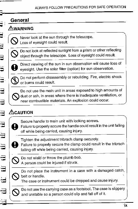
IC Never look at the sun through the telescope.
\: Loss of eyesight could result.
"" Do not look at reflected sunlight from a prism or other reflecting\: object through the telescope. Loss of eyesight could result.
R Direct viewing of the sun in sun observation will cause loss of." eyesight. Use the solar filter (option) for sun observation.
¡( Do not perform disassembly or rebuilding. Fire, electric shock\J or burns could result.
Do not use the main unit in areas exposed to high amounts of~ dust or ash, in areas where there is inadequate ventilation, or
near combustible materials. An explosion could occur.
&CAUTION"'
o Secure handle to main unit with locking screws.Failure to properly secure the handle could result in the unit fallingoff while being carried, causing injury.
o Tighten the adjustment tribrach clamp securely.Failure to properly secure the clamp could result in the tribrachfalling off while being carried, causing injury.
¡t Do not wield or throw the plumb bob.\: A person could be injured if struck.
Do not place the instrument in a case with a damaged catch,~ belt or handle.'The case or instrument could be dropped and cause injury.
IC Do not use the carrying case as a footstool. The case is slippery\: and unstable so a person could slip and falloff of it.
IX

ALWAYS FOLLOW PRECAUTIONS FOR SAFE OPERATION
Power Supply
&WARNING
¡l Do not use voltage other than the specified power supply voltage.\. Fire or electrical shock could result.
.. Use only the specified battery charger to recharge the batteries.
V Other chargers may be of different voltage rating or polaritycausing sparking which could lead to fire or burns.
¡l Do not place articles such as clothing on the battery power\. charger while charging batteries.
Sparks could be induced leading to fire.
ß) Do not use damaged power cords, plugs or loose outlets.Fire or electric shock could result.
ß)Do not use batteries or the battery charger if wet.Resultant shorting could lead to fire or burns.Battery BDC25A meets IPX7 specification for waterproofing(immersion-proof). But shorting could occur if the terminalsbecome wet.
Do not use power cords other than those designated.Fire or electric shock could result.ß)
.. To prevent shorting of the battery in storage, apply insulating
V tape or the equivalent to the battery terminals.Otherwise shorting could occur resulting in fire or burns.
¡l Do not heat or throw batteries into fire.\. An explosion could occur resulting in injury.
&CAUTION
¡l Do not connect or disconnect power supply plugs with wet hands.\. Electric shock could result.
¡l Do not touch liquid leaking from batteries.\. Harmful chemicals could cause burns or blisters.
x
E;
E
E
E-
~E
E;
E
EJ
l~-(!i .,,¡ -
r...":;'
~~ ~~r:G
~:
a
r~r..~r--p~'" ..i.
li~- -i
~'" ..
~~ -l- ,i=i=., :L:
""',"-=..l~
~!- :i.";
~.
ALWAYS FOLLOW PRECAUTIONS FOR SAFE OPERATION
Tripod
~CAUTION
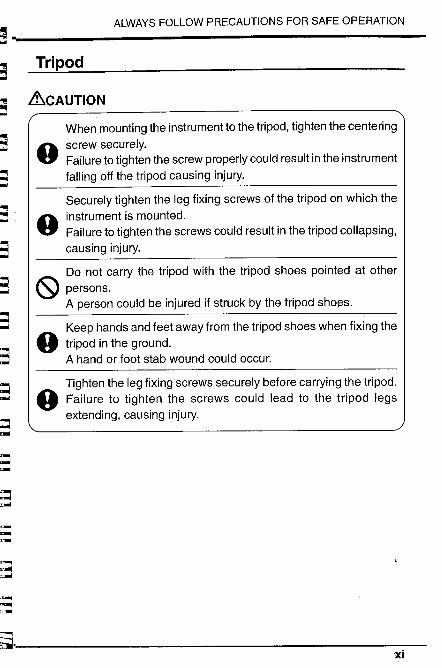
When mounting the instrument to the tripod, tighten the centeringscrew securely.Failure to tighten the screw properly could result in the instrumentfalling off the tripod causing injury.
Securely tighten the leg fixing screws of the tripod on which theinstrument is mounted.Failure to tighten the screws could result in the tripod collapsing,causing injury.
Do not carry the tripod with the tripod shoes pointed at other
(S persons.A person could be injured if struck by the tripod shoßs.
9
9
Keep hands and feet away from the tripod shoes when fixing the
9 tripod in the ground.A hand or foot stab wound could occur.
9 Tighten the leg fixing screws securely before carrying the tripod.Failure to tighten the screws could lead to the tripod legsextending, causing injury.
xi
FEATURES
I FEATURES
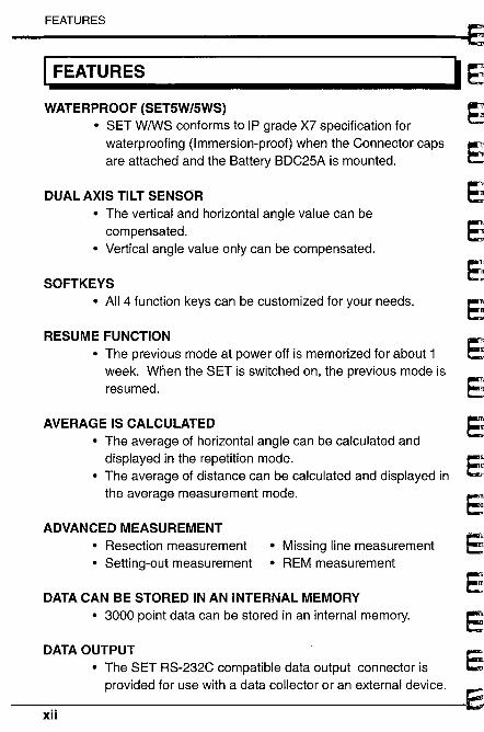
WATERPROOF (SET5W/5WS). SET W/WS conforms to IP grade X7 specification for
waterproofing (Immersion-proof) when the Connector capsare attached and the Battery BDC25A is mounted.
DUAL AXIS TILT SENSOR· The vertical and horizontal angle value can be
compensated.. Vertical angle value only can be compensated.
SOFTKEYS· All 4 function keys can be customized for your needs.
RESUME FUNCTION· The previous mode at power off is memorized for about 1
week. Wnen the SET is switched on, the previous mode isresumed.
AVERAGE IS CALCULATED· The average of horizontal angle can be calculated and
displayed in the repetition mode.· The average of distance can be calculated and displayed in
the average measurement mode.
ADVANCED MEASUREMENT. Resection measurement. Setting-out measurement
· Missing line measurement· REM measurement
DATA CAN BE STORED IN AN INTERNAL MEMORY. 3000 point data can be stored in an internal memory.
DATA OUTPUT· The SET RS-232C compatible data output connector is
provided for use with a data collector or an external device.
xii
Eef;
E;
EE
E:
E
~E
~
b~ I EXPLANATION OF SOFT
KEYS
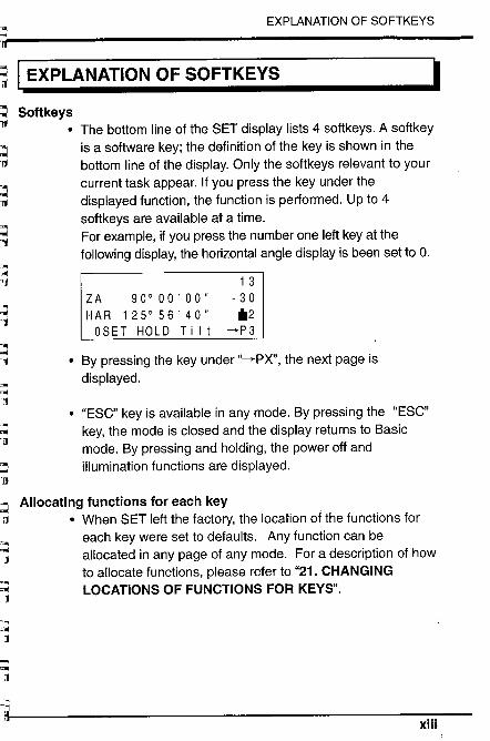
b Softkeysri . The bottom line of the SET display lists 4 softkeys. A softkey
is a softare key; the definition of the key is shown in the
bottom line of the display. Only the softkeys relevant to yourcurrent task appear. If you press the key under thedisplayed function, the function is performed. Up to 4softkeys are available at a time.For example, if you press the number one left key at thefollowing display, the horizontal angle display is been set to O.c
~br-:-6L~~L:~L~
~NI
EXPLANATION OF SOFTKEYS
I
ZA 90°00'00"HAR 125°56'40"
OSET HOLD Ti It
13- 30*2
-+P3
. By pressing the key under "-+PX", the next page is
displayed.
. "ESC" key is available in any mode. By pressing the "ESC"key, the mode is closed and the display returns to Basicmode. By pressing and holding, the power off andillumination functions are displayed.
Allocating functions for each key. When SET left the factory, the location of the functions for
each key were set to defaults. Any function can beallocated in any page of any mode. For a description of howto allocate functions, please refer to "21. CHANGINGLOCATIONS OF FUNCTIONS FOR KEYS".
xiii
HOW TO USE THIS MANUAL
I HOW TO USE THIS MANUAL
. The SET allows you to change the location of functions foreach key, so it is difficult to determine on which mode andpage a function is located.Therefore, in this manual, the operations are mainlyexplained using the default location of the functions for keys.
. Typefaces are used in this manual as follows:
-cKey~ Indicates a keyboard key that causes an immediateaction.Examples: -cSdisb, -c ¡ ~, -c t~, -cEnter~ .
. NOTE Indicates additional information.
.IMPORTANT Indicates important information.
. PRECAUTION Indicates precaution information.
. EXAMPLE Indicates an operation example.
~ EXPLANATION Indicates an explanation for a particular term or opera-
tion.
. PROCEDURE Indicates an operation procedure.
xiv
E
E
E
EE
E
~
L..
l..
~
L..
~ 1.i¡;
~
~ 2.~¡ 3.;¡
~L 4...f1
L... 5.ITI!l
6~i:1~..11
~~: 1
¡~:- ,
~~ ,¡- ¡
I-:1- j
~..- 1
~~- .¡- J
~~
~
tIntroduction
PR ECAUTIONS ..................................... ................. 3
PARTS OF THE INSTRUMENT ........................ 4
DISPLAY SYMBOLS ..............................................6
KEY FUNCTIONS .................................................. 7
MODE DIAGRAM ................................................. 10
1
2
E
E:
E;
Ec
E
E:
Ei
E:,.
E:
E'
E'
E
~
;-b3 11.:' -o~~~8s~=i';
d::::::.
~3~; :-.:
3S:,:3
;;3
;;;'::",:;
~
1. PRECAUTIONS
PRECAUTIONSI
. Never place the SET directly on the ground.Avoid damaging the tripod head and centering screw with sandor dust.
o Do not aim the telescope at the sun.Avoid damaging the LED of the EDM by using a solar fiterwhen the telescope is pointed at the sun.
· Protect the SET with an umbrella against direct sunlight, rainand humidity (SET F/FS).
o Handle the SET with care. Avoid heavy shocks or vibration.
o When the operator leaves the SET, the vinyl cover should beplaced on the instrument.
. Always switch the power off before removing the standard battery.
o Remove the standard battery from the SET before putting it inthe carrying case.When the SET is placed in the carrying case, follow the layout plan.
o Make sure that the inside of the carrying case and theinstrument are dry before closing the case. If moisture istrapped inside the case, it may cause the instrument to rust.
PRECAUTION for SET 5W/5WSo SET WIWS conforms to IP grade X7 specification for
waterproofing (Immersion-proof) only when the Connector capsare attached and the Battery BDC25Ais mounted. IPX7 doesnot guarantee the instrument if it is used or left in water.
Degree of water resistanceo Mount the Battery BDC25A and attach the Connector caps
correctly. When remounting the battery or Connector caps,make sure water does not come in contact with the batteryterminals and connectors. If moisture enters the inside of theinstrument, it could damage the product.
o Make sure that the inside of the carrying case and the
instrument are dry before closing the case. If moisture istrapped inside the case, it may cause the instrument to rust.
o The standard or opuonal-accessories otherwise the Battery
BDC25A do not meet IPX7 specifications.
~
2. PARTS OF THE INSTRUMENT
12. PARTS OF THE INSTRUMENT
æ
æ
æ
4f
æ
~
o
o
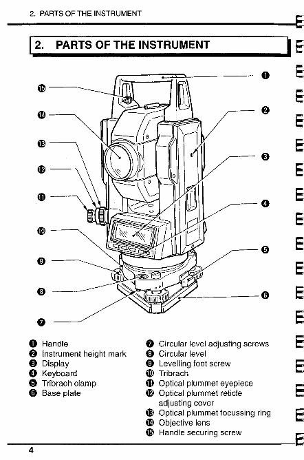
8o Handle8 Instrument height mark
o Displayø Keyboard
o Tribrach clamp
o Base plate
8 Circular level adjusting screws
o Circular levelo Levelling foot screw
~ Tribrach
æ Optical plummet eyepiece
4f Optical plummet reticleadjusting cover
æ Optical plummet focussing ring
æ Objective lens
æ Handle securing screw
4
~~
o
f.
o
ø
o
o
.~
2. PARTS OF THE INSTRUMENT~~i!- .-b: i)
æ
~... W
~ ~
~ w æ
b3 ~..-
~ ~~-
~ ~ æ~ '1
~-;3~
~;3 m æ
~ ~
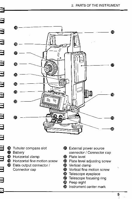
~~ æ Tubular compass slot m External power source
æ Battery connector / Connector cap
'3 æ Horizontal clamp ~ Plate level-=-- ! æ Horizontal fine motion screw ~ Plate level adjusting screw
~ Data output connector / ~ Vertical clamp
~3 ~"'- Connector cap Vertical fine motion screw, ,
W Telescope eyepiece
-=3~ Telescope focusing ringW Peep sighti) Instrument center mark~
.~
3. DISPLAY SYMBOLS
13. DISPLAY SYMBOLS
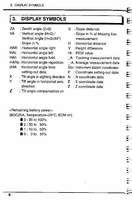
ZA : Zenith angle (Z=O)VA : Vertical angle (H=O) /
Vertical angle (H=0:!900): Slope in %
HAR : Horizontal angle rightHAL : Horizontal angle leftHAh : Horizontal angle holdHARp: Horizontal angle repetitiondHA : Horizontal angle from
setting-out dataX : Tilt angle in sighting directionY : Tilt angle in horizontal axis
direction£ : Tilt angle compensation on
-cRemaining battery power~
(BDC25A, Temperature=25°C, EDM on). 3 : 90 to 100%. 2 : 50 to 90%. 1 : 10 to 50%. 0: 0 to 10%
6
S : Slope distance: Slope in % at Missing linemeasurement
H : Horizontal distanceV : Height differenceHt. : REM value_tk : Tracking measurement data_-A: Average measurement dataStn: Instrument station coordinates
P : Coordinate setting-out dataN : N coordinate dataE : E coordinate dataZ : Z coordinate data
I .1
~~14.
f1
~R.~~~~~~~~t;;1l
~~ ;;~~-
~~
~7"-.
~.. .
4. KEY FUNCTIONS
IKEY FUNCTIONS
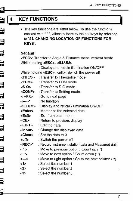
· The key functions are listed below. To use the functionsmarked with" * ", allocate them to the softkeys by referringto "21. CHANGING LOCATION OF FUNCTIONS FORKEYS".
General-cESC~: Transfer to Angle & Distance measurement modeWhile holding -cESC~, -cILLUM~
: Display and reticle illumination ON/OFFWhile holding -cESC~, -cofb: Switch the power off-cTHEO~ : Transfer to Theodolite mode-cEDM~ : Transfer to EDM mode-cS-O~ : Transfer to S-O mode-cCONF~ : Transfer to Setting mode-cPX~ : Go to next page-c---~* : No function
-cILLUM~ : Display and reticle illumination ON/OFF-cEnter~ : Memorize the selected data-cExib : Exit from each mode
-cCE~ : Return to previous display-cEDIT~ : Edit the data-clnpub : Change the displayed data-cClear~ : Set the data to 0-coff~ : Switch the power off
-cREC~* : Record Instrument station data and Measured data-c t ~ : Move to previous option / Count up (*1)
-c l ~ : Move to next option / Count down (*1)
-c-+~ : Move to right option / Go to the next column (*1)-cb : Select the number 1
-c2~ : Select the number 2-c3~ : Select the number 3
7,
4. KEY FUNCTIONS
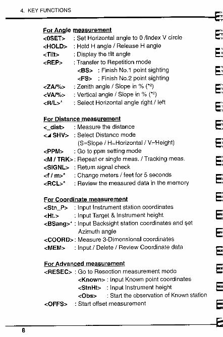
For Angle measurement-cOSET~ : Set Horizontal angle to 0 /Index V circle-cHOLD~ : Hold H angle / Release H angle-cTilt~ : Display the tilt angle-cREP~ : Transfer to Repetition mode
-cBS~ : Finish No.1 point sighting-cFS~ : Finish NO.2 point sighting
: Zenith angle / Slope in % (*2): Vertical angle / Slope in % (*2): Select Horizontal angle right / left
-cZAl%~
-cVAI%~
-cRlL~*
For Distance measurement-c_disb : Measure the distance
-c~ SHV~ : Select Distance mode(S=Slope / H=Horizontal / V=Height)
-cPPM~ : Go to ppm setting mode-cM I TRK~: Repeat or single meas. / Tracking meas.-cSIGNL~ : Return signal check-cf I m~* : Change meters / feet for 5 seconds-cRCL:.* : Review the measured data in the memory
For Coordinate measurement-cStn_P~ : Input Instrument station coordinates-cHt.~ : Input Target & Instrument height
-cBSang~* : Input Backsight station coordinates and setAzimuth angle
-cCOORD~: Measure 3-Dimensional coordinates-cMEM~ : Input / Delete / Review Coordinate data
For Advanced measurement-cRESEC~ : Go to Resection measurement mode
-cKnown~ : Input Known point coordinates-cStnHt~ : Input Instrument height-cObs~ : Start the observation of Known station
-cOFFS~ : Start offset measurement
8
E
E
E
E
E~
E
E
E
E
E
E
E
C
~
~~.='~;:
~~~~~ssS:' '=~~3.,
~~~~=3
~,~
~~
~
4. KEY FUNCTIONS
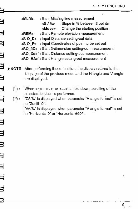
-cMLM~ : Start Missing line measurement-cS / %~ : Slope in % between 2 points-cMove~ : Change the starting position
-cREM~ : Start Remote elevation measurement-cS-O~D~ : Input Distance setting-out data-cS-O_P~ : Input Coordinates of point to be set out-cSO_3D~ : Start 3-dimension setting-out measurement-cSO_Xd~*: Start Distance setting-out measurement-cSO_HA~*: Start H angle setting-out measurement
~ NOTE After performing these function, the display returns to the1 st page of the previous mode and the H angle and Vangieare displayed.
(*1): When -c 1 ~ , -c l ~ or -c-+~ is held down, scrolling of theselected function is performed.
(*2): "ZAI%" is displayed when parameter "Vangie format" is set
to "Zenith 0"."VAI%" is displayed when parameter "Vangie format" is setto "Horizontal 0" or "Horizontal :t90o".
9,
5. MODE DIAGRAM J
I~15. MODE DIAGRAM
Basic mode
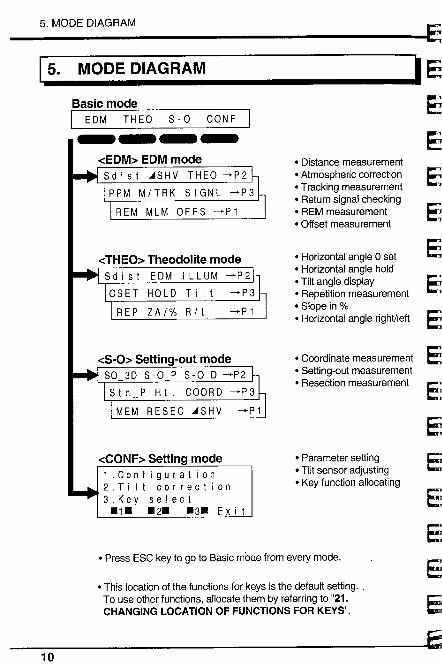
I EDM THEO 8-0 CONF-----cEDM~ EDM mode8dist ~8HV THEO~P2PPM M/TRK 8 I GNL ~P3
REM MLM OFF8 ~P1
-cTHEO~ Theodolite mode8dist EDM ILLUM ~P2
HO L D T i I t
ZA/% R/L
-cS-O~ Setting-out mode80 3D 8,0 P 8-0 D ~P2
8 t n P H t. COOR D ~P 3
MEM RE8EC ~8HV
-cCONF~ Setting mode1.Conf igurat ion2.Tilt correction3.Key select-1- -2- -3-Exit
o Distance measuremento Atmospheric correctiono Tracking measurement
. Return signal checking
. REM measurement
. Offset measurement
. Horizontal angle 0 set
. Horizontal angle hold
. Tilt angle displayo Repetition measurement
. Slope in %o Horizontal angle right/left
o Coordinate measuremento Setting-out measuremento Resection measurement
o Parameter settingo Tilt sensor adjustingo Key function allocating
o Press ESC key to go to Basic rnode from every mode.
o This location of the functions for keys is the default setting. _
To use other functions, allocate them by referring to "21.CHANGING LOCATION OF FUNCTIONS FOR KEYS".
E
E
E
E
E
E
E
EC
~10
~
~r¡rr~.r~::~;---~
~~ .~~~~-~:.:;-::
~~~B~30='
~,~
s
Preparation for measurement
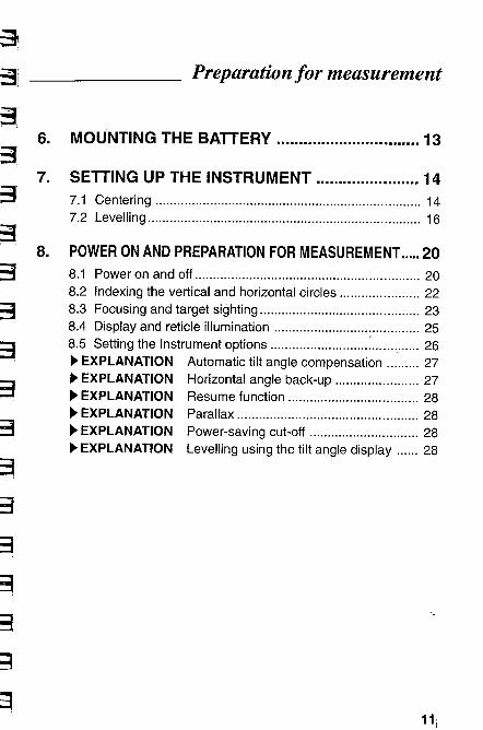
6. MOUNTING THE BATTERy........................ 13
7. SETTING UP THE INSTRUMENT .................... 147.1 Centering ......................................................................... 147.2 Levelling ....................................................................... 16
8. POWER ON AND PREPARATION FOR MEASUREMENT .... 20
8.1 Power on and off .............................................................. 208.2 Indexing the vertical and horizontal circles ...................... 228.3 Focusing and target sighting............................................ 238.4 Display and reticle illumination .........................;............. 258.5 Setting the Instrument options ........................................ 26~ EXPLANATION Automatic tilt angle compensation ......... 27~ EXPLANATION Horizontal angle back-up ....................... 27~ EXPLANATION Resume function ................................... 28~ EXPLANATION Parallax ................................................. 28~ EXPLANATION Power-saving cut-off ............................. 28~ EXPLANATION Levelling using the tilt angle display...... 28
11;
12
E
E
E
~E
E
E
9
::~ 16.
~~~~3
~~:3
~~~3:,;:-~
~~3
~~3
~3
6. MOUNTING THE BATTERY
IMOUNTING THE BATTERY
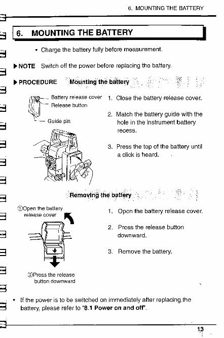
. Charge the battery fully before measurement.
~ NOTE Switch off the power before replacing the battery.
~ PROCEDURE ivqllnting'th~ battery
~~ Battery release cover
.,iii~ Release button, ~,
Guide pin
1. Close the battery release cover.
2. Match the battery guide with thehole in the instrument batteryrecess.
3. Press the top of the battery untila click is heard.
llemc)\(iilgtlîê batt~l'
(DOpen the batteryrelease cover '\
/J,
-u
(gPress the releasebutton downward
1. Open the battery release cover.
2. Press the release button
downward.
3. Remove the battery.
~.,~· If the power is to be switched on immediately after replacingJhe
battery, please refer to "8.1 Power on and off".
~1,3"
7.1 Centring
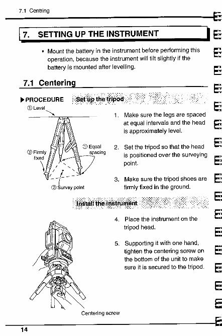
. Mount the battery in the instrument before performing thisoperation, because the instrument wil tilt slightly if thebattery is mounted after levelling.
17. SETTING UP THE INSTRUMENT
7.1
~ PROCEDURECD Level~ 1. Make sure the legs are spaced
at equal intervals and the head Eis approximately leveL.
2. Set the tripod so that the head Eis positioned over the surveying
Epoint.
3. Make sure the tripod shoes are Efirmly fixed in the ground.
E
4. Place the instrument on the Etripod head.
E5. Supporting it with one hand,
tighten the centering screw onthe bottom of the unit to makesure it is secured to the tripod.
ø Firmiy~ ~\\fixed \'0\ ../ ../~ -l- ~ ~
ø Survey point
Centering screw
14
j
~~.~~~~~~~~~~~~'d~'.
~=
~
7. SETTING UP THE INSTRUMENT
a._'I
~
v;; .d~\; --".:,'-.', /":-;:øf;-- -:\;~:- -At'"
::::WfJra;,;",
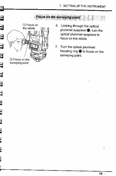
6. Looking through the optical
plummet eyepiece 41, turn theoptical plummet eyepiece tofocus on the reticle.
7. Turn the optical plummetfocusing ring ll to focus on thesurveying point.
15 "
7.2 Levelling
7.2 Levellng
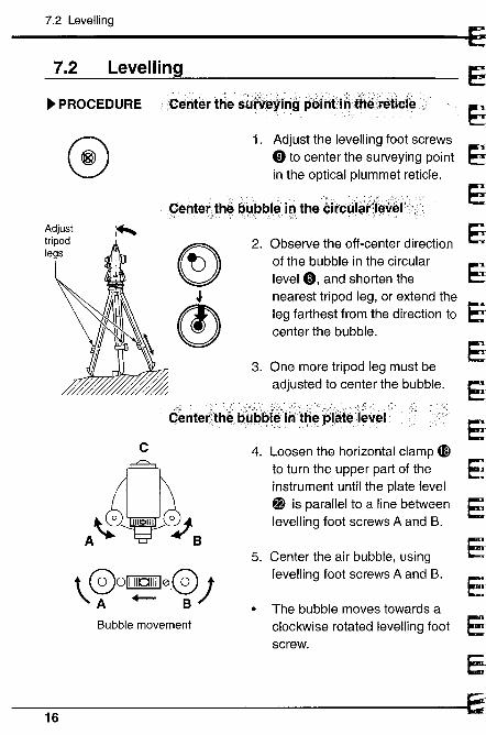
~ PROCEDURE Center the su~~e'ihgp&iritJrith~¡l"eticle ....~
o 1. Adjust the levelling foot screwsCD to center the surveying point
in the optical plummet reticle.
~I
çenterthè bUbblein theCitc~låÌ'(!¡.Ø~~I'
~l
(!
2. Observe the off-center directionof the bubble in the circularlevel 0, and shorten thenearest tripod leg, or extend theleg farthest from the direction tocenter the bubble.
3. One more tripod leg must beadjusted to center the bubble.
Gènterth~.'l)~l)bì~i~tR4~låte;¡~ièl .
C
1 001111101111100;
'A .- BBubble movement
4. Loosen the horizontal clamp 4nto turn the upper part of theinstrument until the plate level~ is parallel to a line betweenlevelling foot screws A and B.
5. Center the air bubble, usinglevelling foot screws A and B.
· The bubble moves towards a
clockwise rotated levelling footscrew.
~.
E
eEEE
E
~.
E.
E
16EJ
S88SSSas&3
3~3
;3~3~::':::".;~~~
;3~"~
~-
7. SETTING UP THE INSTRUMENT
,- :"'---' '- - --'; ,', -'.:'rut~Jlòo. a'~d~~n't~l'th~;~ij~bì~
c90°1' ~
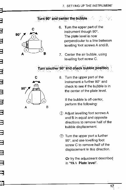
~A B6. Turn the upper part of the
instrument though 90°.
The plate level is nowperpendicular to a line betweenlevelling foot screws A and B.
7. Center the air bubble, using
levelling foot screw C.
':_'::?:_ ___'_'_:';.:,:,:,::,:,.,_:)__::;:',::,....:':;';,..:___:_:,:'0 -'::-":,,,,;,:::::,_ __,"'\,'.--'-:_':_-.0,_/' '
T~rpanfttíer~oo~ri~....c~~cR.~~bbl~~b~.itiOQ ......
c..9u¡' A
èUA B
8. Turn the upper part of the
instrument a further 90° andcheck to see if the bi.bble is inthe center of the plate leveL.
If the bubble is off-center,perform the following:
CD Adjust levelling foot screws Aand B in equal and oppositedirections to remove half of thebubble displacement.
en Turn the upper part a further90°, and use levelling footscrew C to remove half of thedisplacement in this direction.
Or try the adjustment describeain "19.1 Plate level".
17
7.2 Levelling
9. Turn the instrument and checkto see if the air bubble is inthe same position for anyposition of the upper part.If it is not, repeat the levellingprocedure.
10. Loosen the centering screwslightly.
11. Looking through the opticalplummet eyepiece, slide theinstrument over the tripod headuntil the surveying point isexactly centered in the reticle.
12. Retighten the centering screwsecurely.
13. Check again to make sure thebubble in the plate level iscentered. If not, repeat theprocedures starting from step 4.
18 ~
7. SETTING UP THE INSTRUMENT
~-r-3
~~~
~~d~~as:3a~3
~3
~~-3
~-~
___ "._', -c. "',_-- -';~y~rth~Sf.~~~YÎng. q~!HJ
10. Turn the tribrach shifting clampcounterclockwise.Shiftingtribrach can beadjusted up to :J8mm.
11. Looking through the opticalplummet eyepiece, adjust theinstrument position on thetribrach to center the surveyingpoint.
12. Tighten the shifting clamp to fixthe instrument in the centerposition.
~-~
~ 19
8.1 Power on and off
18. POWER ON AND PREPARATION FOR MEASUREMENT I
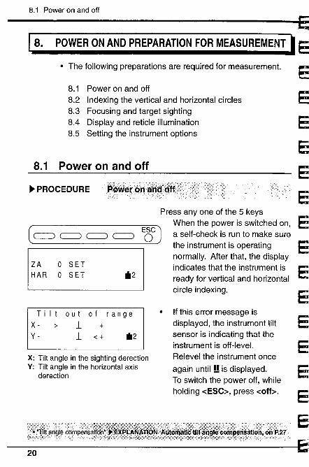
· The following preparations are required for measurement.
8.1 Power on and off
8.2 Indexing the vertical and horizontal circles8.3 Focusing and target sighting8.4 Display and reticle illumination8.5 Setting the instrument options
8.1 Power on and off
~ PROCEDURE~\':r~_'))i,:::',:;:c.- :"':":,:: ';_:_-~'Pøweréin .
Press anyone of the 5 keysWhen the power is switched on,
( ~ ~ c: c: EÔG J a self-check is run to make surethe instrument is operatingnormally. After that, the displayindicates that the instrument isready for vertical and horizontalcircle indexing.
ZA
HAR
o SETo SET il2
Tilt out of rangeX - ;: l +y - l o( il2
If this error message isdisplayed, the instrument tiltsensor is indicating that theinstrument is off-leveL.Relevel the instrument once
again until!! is displayed.To switch the power off, whileholding -cESC~, press -coff~.
X: Tilt angle in the sighting derectionY: Tilt angle in the horizontal axis
derection
r-
~1
tj"--
~
!r
S
B--
."
~
~
8. POWER ON AND PREPARATION FOR MEASUREMENT
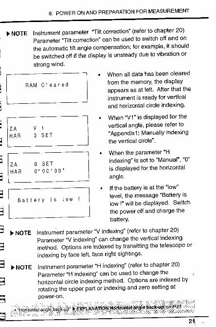
~ NOTE Instrument parameter "Tilt correction" (refer to chapter 20)Parameter "Tilt correction" can be used to switch off and onthe automatic tilt angle compensation; for example, it shouldbe switched off if the display is unsteady due to vibration orstrong wind.
. When all data has been clearedfrom the memory, the displayappears as at left. After that theinstrument is ready for verticaland horizontal circle indexing.
When "V1" is displayed for thevertical angle, please refer to"Appendix1: Manually indexingthe vertical circle".
RAM Cleared
~""
~ ZA
HAR
V 1
o SET
~~ When the parameter "H
indexing" is set to "Manual", "0"is displayed for the horizontalangle.
If the battery is at the "low"level, the message "Battery islow!" will be displayed. Switchthe power off and charge thebattery.
~ NOTE Instrument parameter "V indexing" (refer to chapter 20)Parameter "V indexing" can change the vertical indexingmethod. Options are indexed by transitting the telescope orindexing by face left, face right sightings.
ZA
HAR
o SET0°00'00"~
~-;~
~~;_;:
:3
3~3
;-3
~~
~-~
Battery is low
~ NOTE Instrument parameter "H indexing" (refer to chapter 20)Parameter "H indexing" can be used to change thehorizontal circle indexing method. Options are indexed byrotating the upper part or indexing and zero setting atpower-on.
~;;l-8r¡io¡'lå'.ab¡j¡~:bå8k:ÛB';i;_~j(~GiNAt--.Z: t\\-:rJ :;(- --'~/ :::-_:-' __-.:;,~::" - --- :l:':'\--- - 4T)~~~, :h~:--,' .:'Hf\. )d-tt:i:-;:::~~::;;:C_:--?:~:t:.'.. '--::)i\??---s
21-i
8.1 Indexing the vertical and horizontal circles
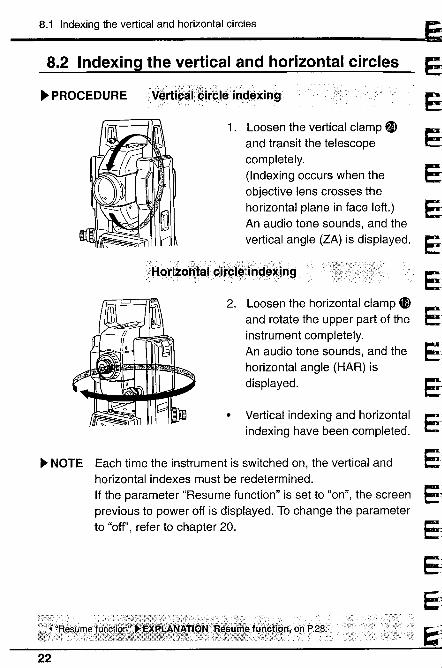
8.2 Indexing the vertical and horizontal circles
~ PROCEDURE V~rti~él?~itçle'ind.exjn9'
1. Loosen the vertical clamp ~and transit the telescopecompletely.
(Indexing occurs when theobjective lens crosses thehorizontal plane in face left.)An audio tone sounds, and thevertical angle (ZA) is displayed.
/Hori~O"Jãl_Oif§I~IH9~*i.n9
2. Loosen the horizontal clamp ~and rotate the upper part of theinstrument completely.
An audio tone sounds, and thehorizontal angle (HAR) isdisplayed.
Vertical indexing and horizontalindexing have been completed.
~ NOTE Each time the instrument is switched on, the vertical andhorizontal indexes must be redetermined.If the parameter "Resume function" is set to "on", the screenprevious to power off is displayed. To change the parameterto "off", refer to chapter 20.
22
~s~~a¿-j~~_.-~~-~
~:;,.:
8. POWER ON AND PREPARATION FOR MEASUREMENT
8.3 Focusing and target sighting
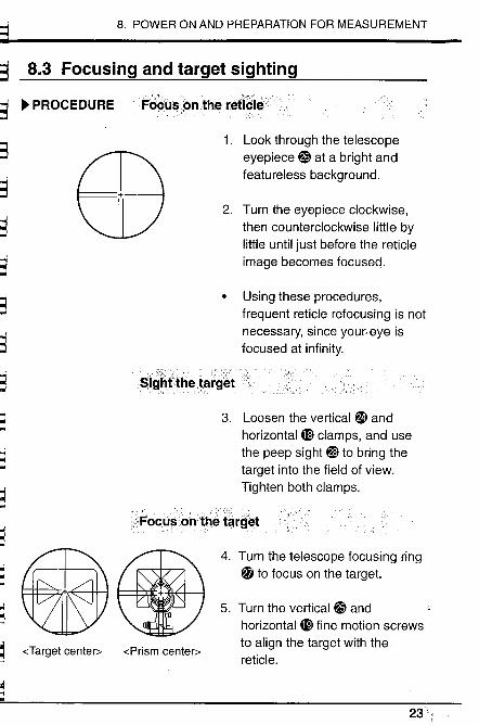
~ PROCEDURE FøÖlÍ$ol'theréficl~
EB
~~Ir::"'
::;~~
~~-
~IF"C_
~""~
==~ ~
S¡g~ftfie. .target
1. Look through the telescope
eyepiece ~ at a bright andfeatureless background.
2. Turn the eyepiece clockwise,
then counterclockwise little bylittle until just before the reticleimage becomes focused.
Using these procedures,
frequent reticle refocusing is notnecessary, since your, eye isfocused at infinity.
3. Loosen the vertical ~ andhorizontal 4E clamps, and usethe peep sight €Y to bring thetarget into the field of view.Tighten both clamps.
Focu$ôntM tårg~t
-(Target center)o -(Prism center)o
4. Turn the telescope focusing ring~ to focus on the target.
5. Turn the vertical ~ andhorizontal 4D fine motion screwsto align the target with thereticle.
~;J
~!::-
:.i
.~
:¡~~1
:j
~
.-~
23
8.3 Focusing and target sighting
The last adjustment of each finemotion screw should be in theclockwise direction.
'.'.::.""'-. ................"'..... ............."-'.. .. ............................................
FlØ¡;djÜšt tliê'1èiêll~Hnt!l;..therll!a;."O .P~r~iI~~åir
6. Readjust the focus with the
focusing ring ~ until there is noparallax between the targetimage and the reticle.
~ NOTE Observe to the same point of the reticle when the telescopeface is changed.
';;;,:t~v;;~(t':+-:;:'-;:';, '::: )--.: -, , , _ :-::~ :.-c..i:_~;::':/://:::;:',,',::::::r( :;,::/,'-'/:;::-\,:':::f\; ;,::A:,r7::;)';~:l/':f,: :';".:, ':,:::~: /L::: :::-'\.:-:,:!,;J!here iSfl.O "paraltax~'.EXF'L.NA T1ÒN +í:~rli"lix¡öhP.2.8.');)lU~rgg;F"'~f'i/'" " ----, ------------- ---- _____u__, -';:,.-, ',', - , \WK:).-S'" "~h~'-:W:-;---:-;" ,-' co. ,
24 :j
i
r-h:r c . ~ PROCEDUREii"t)iS'plàyàhdreti6Iè ilQlûiiiå.tiÒnôrloff~r . '. .1~~ Holding -cESC:;, press -cLLUM:;
~~h3
8. POWER ON AND PREPARATION FOR MEASUREMENT
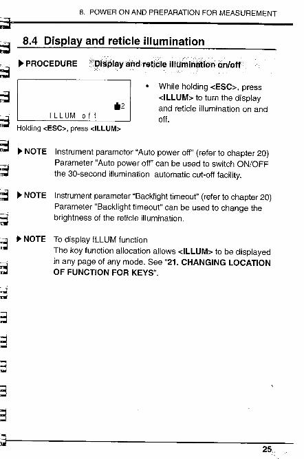
8.4 Display and reticle ilumination
il2
While holding -cESC~, press-cILLUM~ to turn the displayand reticle illumination on andoff.ILL UM 0 f f
~ NOTE Instrument parameter "Auto power off" (refer to chapter 20)Parameter "Auto power off" can be used to switch ON/OFFthe 30-second illumination automatic cut-off facility.
~~
~ NOTE Instrument parameter "Backlight timeout" (refer to chapter 20)Parameter "Backlight timeout" can be used to change thebrightness of the reticle illumination.
~~"~
~'::
~'3
~:3
~':
~L~
..... :jFs"::
~ NOTE To display ILLUM functionThe key function allocation allows -cILLUM~ to be displayedin any page of any mode. See "21. CHANGING LOCATIONOF FUNCTION FOR KEYS".
-;;25,
8.5 Settng the Instrument options
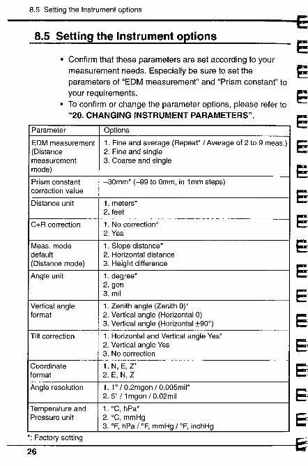
. Confirm that these parameters are set according to your
measurement needs. Especially be sure to set theparameters of "EDM measurement" and "Prism constant" toyour requirements.
· To confirm or change the parameter options, please refer to"20. CHANGING INSTRUMENT PARAMETERS".
8.5 Setting the Instrument options
Parameter Options
EDM measurement 1. Fine and average (Repeat / Average of 2 to 9 meas.)(Distance 2. Fine and singlemeasurement 3. Coarse and singlemode)
Prism constant -30mm* (-99 to Omm, in 1 mm steps)correction value
Distance unit 1. meters*2. feet
C+R correction 1. No correction*2. Yes
Meas. mode 1. Slope distance*default 2. Horizontal distance(Distance mode) 3. Height difference
Angle unit 1. degree*2. gon3. mil
Vertical angle 1. Zenith angle (Zenith 0)*format 2. Vertical angle (Horizontal 0)
3. Vertical angle (Horizontal :t900)
Tilt correction 1. Horizontal and Vertical angle Yes*2. Vertical angle Yes3. No correction
Coordinate 1.N,E,Z*format 2. E, N, Z
Angle resolution 1. 1" / 0.2mgon /0.005mil2. 5" / 1 mgon /0.02mil
Temperature and 1. °C, hPa*Pressure unit 2. °C, mmHg
3. OF, hPa / OF, mmHg / OF, inchHg
*: Factory setting
-~26
-'-.':;.:~'~,'?~-'~:' ~-"",~':""T~-~-~ -.~,~,r ~~~~
~~~3
~3
b3
~
8. POWER ON AND PREPARATION FOR MEASUREMENT
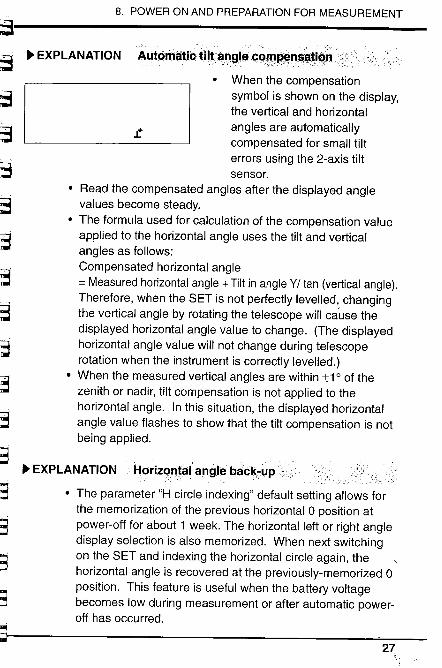
~ EXPLANATION A.utÓitâtiOmtiin!:,RçQrn~;~I1$,i¡lilín;
~:-.~
When the compensationsymbol is shown on the display,the vertical and horizontalangles are automaticallycompensated for small tilterrors using the 2-axis tiltsensor.
· Read the compensated angles after the displayed anglevalues become steady.
· The formula used for calculation of the compensation valueapplied to the horizontal angle uses the tilt and verticalangles as follows:Compensated horizontal angle= Measured horizontal angle + Tilt in angle Y/ tan (vertical angle).Therefore, when the SET is not perfectly levelled, changingthe vertical angle by rotating the telescope will ca'use thedisplayed horizontal angle value to change. (The displayedhorizontal angle value wil not change during telescoperotation when the instrument is correctly levelled.)
· When the measured vertical angles are within :t1 0 of thezenith or nadir, tilt compensation is not applied to thehorizontal angle. In this situation, the displayed horizontalangle value flashes to show that the tilt compensation is notbeing applied.
.t
"'3'tr-m-~ :(
;,,~- ;;;
lOtt,.:._,~~ EXPLANATION Harizant~langiebâok7i.P
. The parameter "H circle indexing" default setting allows forthe memorization of the previous horizontal 0 position atpower-off for about 1 week. The horizontal left or right angledisplay selection is also memorized. When next switchingon the SET and indexing the horizontal circle again, thehorizontal angle is recovered at the previously-memorized 0position. This feature is useful when the battery voltagebecomes low during measurement or after automatic power-off has occurred.
,.;i-~- ~.'::i~~
~3
~~~"."c
.,
27
EXPLANATION
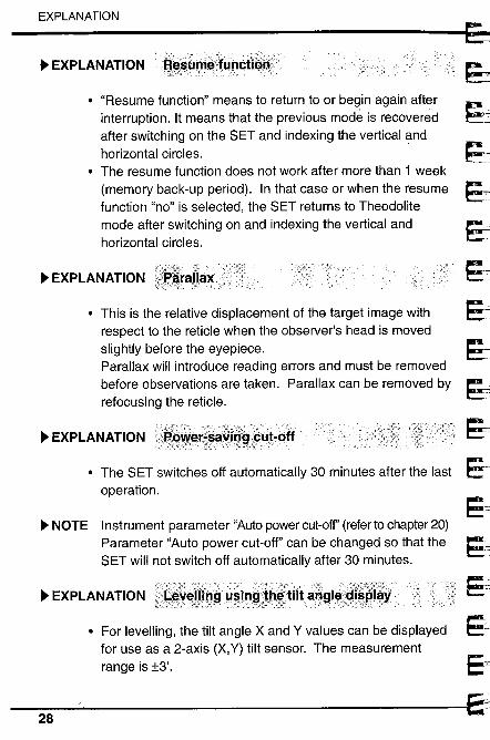
· For levelling, the tilt angle X and Y values can be displayedfor use as a 2-axis (X,Y) tilt sensor. The measurementrange is :13'.
;~h:- _:-';:-;:::",:,'/.:_: : :-:,-:_':i- -: ;:_::;_-:;'\:"::::: it?"~ ,': :,:.-,' ---:':::f:::- _' :::/:,_~,:- ::;:;,~!~~'V!h). ~1.1l9~ H~!p,!l;;l~~tilta.~f,I~¡~i~.el~¥.
~ EXPLANATIONff~~G~ølunctiQQ
· "Resume function" means to return to or begin again afterinterruption. It means that the previous modè is recoveredafter switching on the SET and indexing the vertical andhorizontal circles.
· The resume function does not work after more than 1 week
(memory back-up period). In that case or when the resumefunction "no" is selected, the SET returns to Theodolitemode after switching on and indexing the vertical andhorizontal circles.
~ EXPLANATION
. This is the relative displacement of the target image withrespect to the reticle when the observer's head is movedslightly before the eyepiece.Parallax will introduce reading errors and must be removedbefore observations are taken. Parallax can be removed byrefocusing the reticle.
~ EXPLANATION
· The SET switches off automatically 30 minutes after the lastoperation.
~ NOTE Instrument parameter "Auto power cut-off' (refer to chapter 20)Parameter "Auto power cut-off" can be changed so that theSET will not switch off automatically after 30 minutes.
~ EXPLANATION
28
8. POWER ON AND PREPARATION FOR MEASUREMENT~~L~J_~~,~
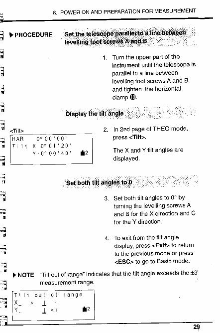
4. To exit from the tilt angledisplay, press -cExit~ to returnto the previous mode or press-cESC~ to go to Basic mode.
~ NOTE "Tilt out of range" indicates that the tilt angle exceeds the :t3'measurement range.
Tilt out of rangeX ;: 1 +Y 1 .: + ~i2
~ PROCEDURE i:.,.......,e..........t...........t...h...........e....'.................t...e..........I.,.e.........................$.................. 'i
løvêOirl~.i~~
1. Turn the upper part of theinstrument until the telescope isparallel to a line betweenlevelling foot screws A and Band tighten the horizontalclamp 4D.
2. In 2nd page of THEO mode,press -cTilb.
The X and Y tilt anglas aredisplayed.
3. Set both tilt angles to 0° byturning the levelling screws Aand B for the X direction and Cfor the Y direction.
~..t~
'.D¡šplãyth~'tiìläk.-_~~'iii dilb~
~~I;b~'u ~
á~,_
t1
HAR 0°00'00"T ¡It X 0° 01 ' 20"
Y-ooOO'40" ~i2
.,II~
:$et.botll
~~~~ \ II
"9....--- ---. .
'" '----i~". ii~_:_~~~ L.JI
"d~:~~i-
~ rC.'3~i:~ L
ini..
29
30 .~
~Lr~r::r:~'~~t3~~~
~S:::;~
~~.':-~-=
~';,,3'l:r,
"~'"iu'-t.,
~
Measurement
9. ANGLE MEASUREMENT ............................. 339.1 Measure the horizontal angle between 2 points ............. 349.2 Set Horizontal circle to a required value ......................... 359.3 Horizontal angle display selection .................................. 369.4 Horizontal angle repetition .............................................. 379.5 Slope in %...................................................................... 39
10. DISTANCE MEASUREMENT .......................... 4010.1 Atmospheric correction ................................................. 4110.2 Return signal checking ................................................. 4410.3 Distance and angle measurement ................................ 4510.4 Tracking measurement .................................................4710.5 Review of measured data ................................'............48
11. COORDINATE MEASUREMENT .................... 4911.1 Instrument station coordinates setting ..........................5011.2 Target height and instrument height setting .................. 5211.3 Azimuth angle setting .................................................... 5311.4 3-Dimensional coordinate measurement .....................56
3f:

32
9. ANGLE MEASUREMENT
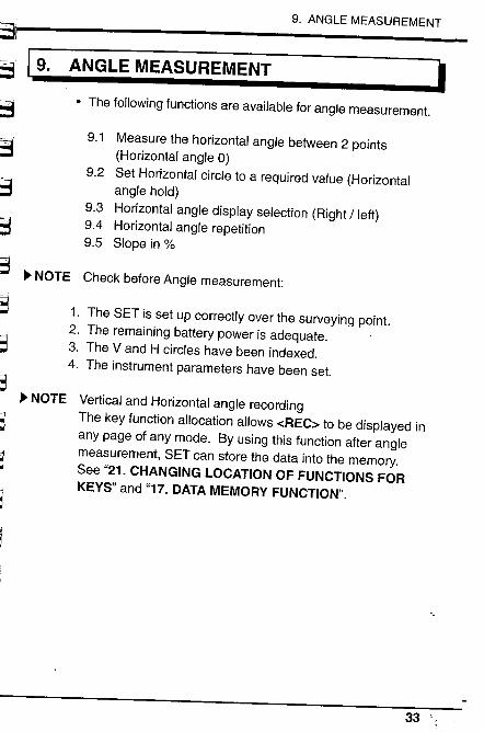
1. The following functions are available for angle measurement.
9.1 Measure the horizontal angle between 2 points
(Horizontal angle 0)Set Horizontal circle to a required value (Horizontalangle hold)Horizontal angle display selection (Right / left)Horizontal angle repetitionSlope in %
9.2
9.39.49.5
1. The SET is set up correctly over the surveying point.2. The remaining battery power is adequate.3. The V and H circles have been indexed.4. The instrument parameters have been set.
jC '=..~~,;;j::l~
Vertical and Horizontal angle recordingThe key function allocation allows -cREC~ to be displayed inany page of any mode. By using this function after anglemeasurement, SET can store the data into the memory.See "21. CHANGING LOCATION OF FUNCTIONS FORKEYS" and "17. DATA MEMORY FUNCTION".
;'.,;;~.;~
~-3
:: ,~ii_-i~~""
..~
:. ~"'~:U¡
b33
9.1 Measure the horizontal angle between 2 points (H angle 0)
ZA 112°21'20"HAR 350°38'10"OSETHOLDTilt
-cOSET~
o
- 30*2
--P 3
In 2nd page of THEO mode
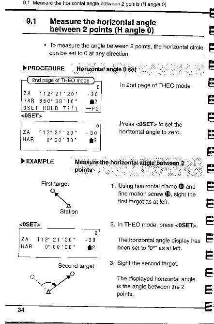
9.1 Measure the horizontal anglebetween 2 points (H angle 0)
. To measure the angle between 2 points, the horizontal circlecan be set to 0 at any direction.
,__ -'.-' ,'.: _C'-'_:"'" ,",-' ":""'"
. PROCEDURE ,!'9i'izahtåf.a'1~le ôsèf ..,
ZA 112°21'20"HAR 0°00'00"
o
- 30*2
Press -cOSET~ to set thehorizontal angle to zero.
. EXAMPLE.."1,~~,.~.~.,~~.fHe...hpr¡~pn
, FJoi Í)ts
First targeto~Station
1. Using horizontal clamp 4E andfine motion screw 4D, sight thefirst target as at left.
-cOSET~ 2. In THEO mode, press -cOSET~.
ZA 112°21'20"HAR 0°00'00"
o
- 30*2
The horizontal angle display hasbeen set to "0°" as at left.
Second target 3. Sight the second target.0/ The displayed horizontal angleis the angle between the 2points.
34
~ 9. ANGLE MEASUREMENT
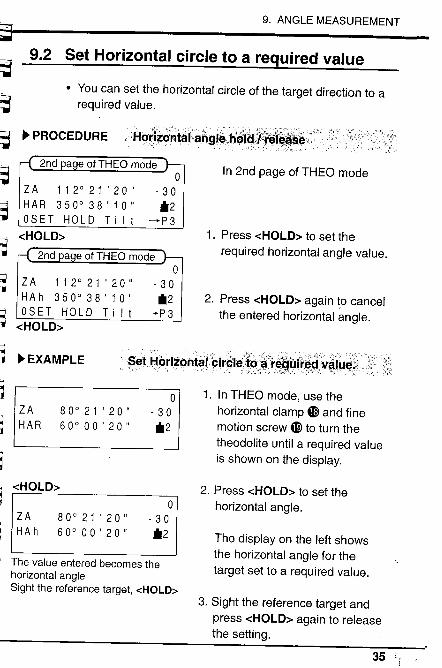
9.2 Set Horizontal circle to a required value~~ · You can set the horizontal circle of the target direction to a
required value.
~~~
~ PROCEDURE Ho....r¡~ó~tá¡\~~g¡øij~(~,dý¥'~I.~."l.~~,;#.'"-',---','--' , '''" ,': -"-__f
ZA 112°21'20"HAR 350°38'10"OSET HOLD Tilt
-cHOLD~~
o
- 30*2
-- P 3
o
, 30*2
-- P 3
~ ZA 112°21'20"HAh 350°38'10"OSET HOLD Ti It
-cHOLD~
o
- 30*2
:.": T~
~~::. ~ EXAMPLE
In 2nd page of THEO mode
1. Press -cHOLD~ to set therequired horizontal angle value.
2. Press -cHOLD~ again to cancelthe entered horizontal angle.
"'..$et.HoriiQntàlbil'~le:lôã:r£åtifV~:v~fu~j';)'-:'-, :--'-, -' ----:~ ': ,:,.., :.:, :::---,-::,:,::;,',' ,,:::"~', '):-;-:___-_\);:':,__,_::;;.-;/--,-,_,-::._'~',.,".~-:-::i--;:;-,~, ;?'~:,::_:-----_":;,"
~ZA
:,~ HAR80°21 '20"60°00'20"
o
- 30*2
i:...,"~: 'i
;;~ -cHOLD~
ë '.
ZA
~;~ H A h~ ,.
80° 21' 20"60° 00'20"
:: The value entered becomes the:r ¡I horizontal angle
Sight the reference target, -(HOLD;:¡¡~..~i¡~
"'~..Di
1. In THEO mode, use thehorizontal clamp Gi and finemotion screw GJ to turn thetheodolite until a required valueis shown on the display.
2. Press -cHOLD~ to set thehorizontal angle.
The display on the left showsthe horizontal angle for thetarget set to a required value.
3. Sight the reference target andpress -cHOLD~ again to releasethe setting.
35
9.3 Horizontal angle display selection (Right / left)
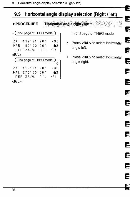
9.3 Horizontal angle display selection (Right ¡left)
Ii
~
~~~~.~J.~d5~
~~1
~
~ PROCEDURE
ZA
HAR
REP-cR/b
112°21'20"90° 00' 00"ZAf% RfL
a e of THEO mode
o
- 30il2
-+P 1
o
ZA 112°21'20" -30HAL 270°00'00" il2
REP ZAf% RfL -+P1-cR/b
In 3rd page ofTHEO mode
· Press -cR/L~ to select horizontalangle left.
· Press -cR/L~ to select horizontalangle right.
36
~~.i. ~
~l;
9. ANGLE MEASUREMENT
~'r,..
t=3
~~
9.4 Horizontal angle repetition
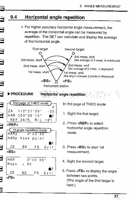
· For higher accuracy horizontal angle measurement, theaverage of the horizontal angle can be measured byrepetition. The SET can calculate and display the averageof the horizontal angle.
First targeta
Second targeta
3rd meas. end(the average af 3 meas. is displayed)
2nd meas. end(the average af 2 meas. is displayed)
1 st meas. end(the angle between 2 paints is displayed)
-cFS~Instrument station
3rd meas. start
~... ~ PROCEDURE
~.~~t3~
Hc)t¡*øntaJáiiglerepetitiori
ZA 112°21'20"HAR 350°38'10"REP ZA/% R/L
-cREP~
o
- 30~i2
-P 1
~~;......=i.'~.;~
i;¡;;'7:~:J
~3
S
CE
-cBS~
~i2BS FS Exit
HAR
R e p s .
CE
-cFS~
0°00'00"00
BS~i2
Ex i t
In 3rd page ofTHEO mode
1. Sight the first target.
2. Press -cREP~ to selecthorizontal angle repetitionmode.
3. Press -cBS~ to start 1 stmeasurement.
4. Sight the second target.
5. Press -cFS~ to display the anglebetween two points.
(The angle of the 2nd target isheld.)
FS
37,
9.4 Horizontal angle repetition
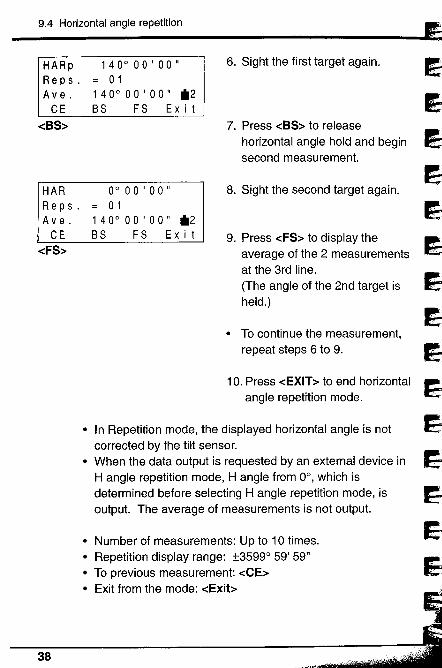
HARpR e p s .
A v e .
CE
-cBS~
1 40° 00 ' 00 '= 01140°00'00" *2BS FS Exit
HAR
R e p s .
A v e .
CE-cFS~
38
0°00'00"01
1 40° 00 ' 00" *2BS FS Exit
6. Sight the first target again.
7. Press -cBS~ to release
horizontal angle hold and beginsecond measurement.
8. Sight the second target again.
9. Press -cFS~ to display theaverage of the 2 measurementsat the 3rd line.
(The angle of the 2nd target isheld.)
· To continue the measurement,
repeat steps 6 to 9.
10. Press -cEXIT~ to end horizontalangle repetition mode.
· In Repetition mode, the displayed horizontal angle is notcorrected by the tilt sensor.
. When the data output is requested by an external device inH angle repetition mode, H angle from 0°, which isdetermined before selecting H angle repetition mode, isoutput. The average of measurements is not output.
. Number of measurements: Up to 10 times.· Repetition display range: :13599° 59' 59"
· To previous measurement: -cCE~· Exit from the mode: -cExib
Il~
~IE1
19~J
í~1l
Eij~...'l=
~~~~.'io--,_
~~~~~,¡R
~" ~Ii .~ .':
;,~~ -:.
;"~.'"'1.
~,~,..:.
;",;;.. .~':.
,. '.;:..-~~:',..
~.~
~'3
9. ANGLE MEASUREMENT
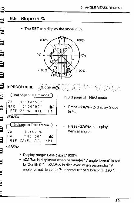
9.5 Slope in %
· The SET can display the slope in %.
0% 0%
~ PROCEDURE ,:Slbp~in\;Jd
In 3rd page of THEO modeZA 90°13'50"HAR 0° 00' 00" il2REP ZA/% R/L ~P1
· Press -cZA/%~ to display Slope
in%.-cZA/%~
a e ofTHEO mode · Press -cZA/%~ to displayVertical angle.VA -0.402 %
HAR 0° 00' 00" il2REP ZA/% R/L -+P1
-cZA/%~
· Display range: Less than :i1 000%· -cZA/%~ is displayed when parameter "Vangie format" is set
to "Zenith 0°". -cZA/%~ is displayed when parameter "Vangle format" is set to "Horizontal 0°" or "Horizontal :i900".
~~r..39;
10.1 Atmospheric correction
110. DISTANCE MEASUREMENT
· The following preparations are required for Distancemeasurement.10.1 Atmospheric correction10.2 Return signal checking
· The distance is measured according to the parameter "EDMmeasurement" (the measurement mode) which you selectedin "8.5 Setting the Instrument options".Refer to chapter 20 to change the measurement mode.
· When the data output is requested by an external device inAverage measurement mode, the data is output the selectednumber of times.
~ NOTE Slope distance recordingThe key function allocation allows -cREC~ to be displayed inany page of any mode. By using this function after distancemeasurement, the SET can store the data into the memory.See "21. CHANGING LOCATION OF FUNCTIONS FORKEYS" and "17. DATA MEMORY FUNCTION".
~ NOTE Change feet / meterThe key function allocation allows -cf/m~ to be displayed inany page of any mode. Press -cf/m~ to change the distanceunit for 5 seconds. See "21. CHANGING LOCATION OFFUNCTIONS FOR KEYS".
40
L
I~~
Ej~~j
~
3E;!-d.~i
~~~~~~. ;;~--,-
~;".' ~I. '!.i
~~'~
lrC~I~ ~:.i
~~. ,;:-i-
~';3
~.~
~'3
10. DISTANCE MEASUREMENT
~:;3
~
10.1 Atmospheric correction
~ NOTE
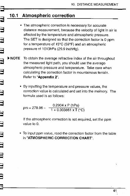
. The atmospheric correction is necessary for accuratedistance measurement, because the velocity of light in air isaffected by the temperature and atmospheric pressure.The SET is designed so that the correction factor is 0 ppmfor a temperature of 15°C (59°F) and an atmosphericpressure of 1 013hPa (29.9 inchHg).
To obtain the average refractive index of the air throughoutthe measured light path, you should use the averageatmospheric pressure and temperature. Take care whencalculating the correction factor in mountainous terrain.Refer to "Appendix 2".
. By inputting the temperature and pressure values, the
correction value is calculated and set into the memory. Theformula used is as follows:
pm = 278.96 -0.2904 x P (hPa)
1 + 0.003661 x T (0C)
If the atmospheric correction is not required, set the ppmvalue to O.
. To input ppm value, read the correction factor from the tablein "ATMOSPHERIC CORRECTION CHART".
41
1 0 .1 Atmospheric correction
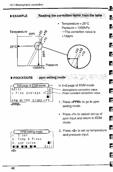
~ EXAMPLE 'J=ea~.!n~t6øê~ßtr~~tlQrl'.i~rlíà¡~irr~~;lb~t~.b.,~\0'
Temperature & ~ppm y. y.
25°C
. Temperature = 25°C
Pressure = 1000hPa-+ The correction value is+ 13ppm
Pressure1000hPa
~ PROCEDURE....... .;:............. ..............:-.'. .............. .....
ppnls~Ít¡n~..mpêlê'
PPM MITRK-cPPM~
PPM settin mode1. 0 set2. Temp & Press3. ppm value.1. .2. .3.
-c2~
.2Ex i t
In 2nd page of EDM modeAtmospheric correction valuePrism constant correction value
1. Press -cPPM~ to go to ppmsetting mode.
. Press -c1 ~ to cancel set up of
ppm input and return to EDMmode.
2. Press -c2~ to set up temperatureand pressure input.
'1~"""'.
~JI)
~-i~~
J~dl
~~~~42

~~!~ir~' n:.,
-'. I¡o.
10. DISTANCE MEASUREMENT
s~3
. t. ..¡.il2
.... Enter
3. Input Temperature using -c t ~
(count up) -c ¡ ~ (count down),and press -cEnter~. (To movethe column, press -c-+~.)
4. Input Pressure.
5. Press -cEnter~ to set Pressure
(EDM mode).
~,.'."r~.
¡;;;;
t:3t.. '. ,c' ,
;-~;;
~;- ~,l::
-c t ~ -c ¡ ~, -c_~-cEnter~
p pm=
Input ppm value
+0 f.r
~3 -cEnter~
.t. il2..¡. .... E n t e r
6. Press -c3~ to set up correctionvalue input.
7. Input the ppm value using -c t ~
(count up) -c ¡ ~ (count down),and press -cEnter~. (To movethe column, press -c-+~.)
~~~:~::
~~~
~~::~~.; IIi- ,po
43';
10.2 Return signal checking
~~E~.1.~~~i't....~i"~'~-
," Tit,.;
17~I.....'..
i
~..'''~-¡1
10.2 Return signal checking
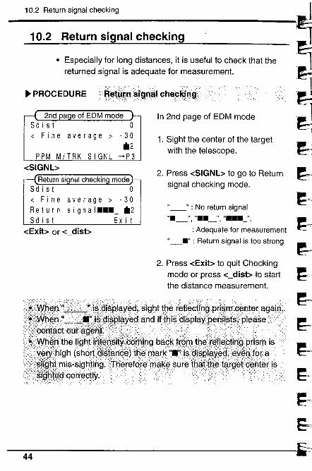
· Especially for long distances, it is useful to check that thereturned signal is adequate for measurement.
~ PROCEDURE~~t~:ijn~ÎfJn~UCheqRjn~;ç
o
- 30
*2PPM M/TRK SIGNL -P3
-cSIGNb
In 2nd page of EDM mode
1. Sight the center of the targetwith the telescope.
2. Press -cSIGNb to go to Returnsignal checking mode.
"_" : No return signalII__", ".._"i 11..._",
: Adequate for measurement
"__" : Return signal is too strong
2. Press -cExib to quit Checkingmode or press -c_disb to star!the distance measurement.
...... , J:',~~
... . .~~-r
~,l:
~J~J.~
í~.J
44
~~~~--
~~~~~t--'~~~-~:-i
~~S=e,- 3'"'" '
~~"..;,,~~ ~
~':3
~-'3
10. DISTANCE MEASUREMENT
10.3 Distance and angle measurement
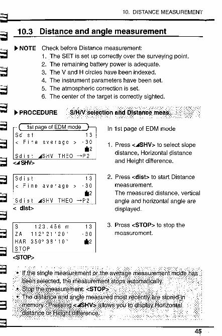
~ NOTE Check before Distance measurement:1. The SET is set up correctly over the sUNeying point.2. The remaining battery power is adequate.3. The V and H circles have been indexed.4. The instrument parameters have been set.5. The atmospheric correction is set.6. The center of the target is correctly sighted.
~ PROCEDURE
1 st pa e of EDM modeS d i s t 1 3~ Fine average ~ -30
"2Sd i s t ~SHV THEO ~P2~ SfS d i s t 1 3~ Fine average ~ -30
"2S d i s t ~S H V THE 0 ~ P 2
-c_disb
S 123.456 mZA 112021'20"HAR 350038'10"STOP
-cSTOP~
1 3
- 30"2
In 1st page of EDM mode
1. Press -c~SHV~ to select slopedistance, Horizontal çlistance
and Height difference.
2. Press -cdisb to start Distancemeasurement.The measured distance, verticalangle and horizontal angle aredisplayed.
3. Press -cSTOP~ to stop themeasurement.
4S
10.3 Distance and angle measurement
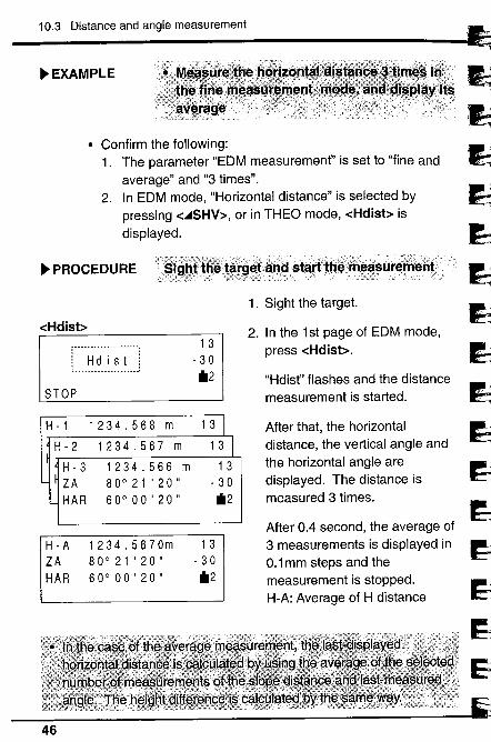
~ EXAMPLE
· Confirm the following:1. The parameter "EDM measurement" is set to "fine and
average" and "3 times".2. In EDM mode, "Horizontal distance" is selected by
pressing -c..SHV~, or in THEO mode, -cHdisb isdisplayed.
~ PROCEDURE
-cHdisb
STOP
H -1
H - 2
H - 3
ZA
HAR
H - A
ZA
HAR
. .! H d i s t !l.......____.........:
1 3
- 30il2
1234.568 m
1234.567 m
1234.566 m80°21'20"60°00'20"
1 3
1 3
13- 30il2
1234.5670m80°21'20"60°00'20"
13- 30il2
_::X ' \i :,:,\::::\:.,: - --- --, ,: ") ::: ;:_ :_i:-:,';:::-:)/ -.:'::::/ '). :,;::. :, '_ ,,'_.'_ ,:--:; -: :' ;::_\?:~:-;: ~ __ ':::-:_
etand 'starttl:è\îf!,.~~uremenf
1. Sight the target.
2. In the 1st page of EDM mode,press -cHdisb.
"Hdist" flashes and the distancemeasurement is started.
,~JJ~
~~
1
~~9~d~
1~__,_J
After that, the horizontaldistance, the vertical angle andthe horizontal angle aredisplayed. The distance ismeasured 3 times.
After 0.4 second, the average of3 measurements is displayed in0.1 mm steps and themeasurement is stopped.H-A: Average of H distance
46
~ 10. DISTANCE MEASUREMENT
j~~~".-ft
~~
~~~~'r rnl
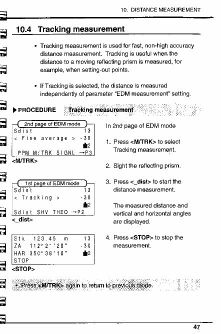
10.4 Tracking measurement
· Tracking measurement is used for fast, non-high accuracydistance measurement. Tracking is useful when thedistance to a moving reflecting prism is measured, forexample, when setting-out points.
. If Tracking is selected, the distance is measuredindependently of parameter "EDM measurement" setting.
~~~~'~
;.~.'T i...
;,.,;:
~,~- :a
"S- ,IL, ,
~
~ PROCEDURE
PPM MITRK SIGNL-cM/TRK~
Sdist SHV THEa-c_disb
13- 30il2
--P 2
Stk 123.45 mZA 112°21'20"HAR 350°38'10"STOP
-cSTOP~
1 3
- 30il2
t()return tqi:;t:
In 2nd page of EDM mode
1. Press -cM/TRK~ to selectTracking measureme.nt.
2. Sight the reflecting prism.
3. Press -c_disb to start thedistance measurement.
The measured distance andvertical and horizontal anglesare displayed.
4. Press -cSTOP~ to stop themeasurement.
47
10.5 Review of measured data
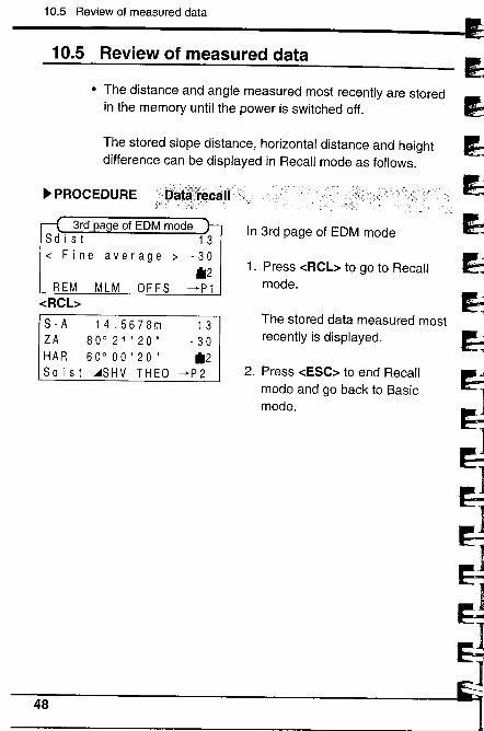
10.5 Review of measured data
· The distance and angle measured most recently are storedin the memory until the power is switched off.
The stored slope distance, horizontal distance and heightdifference can be displayed in Recall mode as follows.
~ PROCEDURE Daté';fÊ!.calit ,v
3rd a e of EDM modeS d i s t 13~ Fine average ~ -30
il2MLM OFFS --P1REM
-cRCbS-A 14.5678mZA 80°21'20"HAR 60°00'20"Sd i s t ASHV THEO
1 3
- 30il2
..p 2
In 3rd page of EDM mode
1. Press -cRCL~ to go to Recallmode.
The stored data measured mostrecently is displayed.
2. Press -cESC~ to end Recall
mode and go back to Basicmode.
~~~,'...i5'ï~iJiJ
~íírií~~~48
11. COORDINATE MEASUREMENT~~ 111.
~=
~~~.~
~~~~~~
~~~o~
~.,:;
~'~
~'~
~
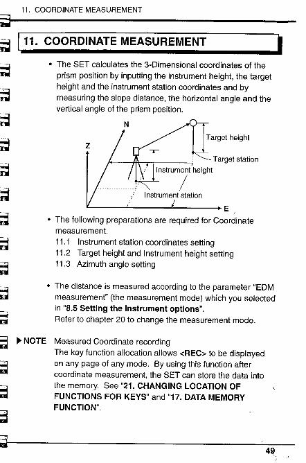
COORDINATE MEASUREMENT I· The SET calculates the 3-Dimensional coordinates of the
prism position by inputting the instrument height, the targetheight and the instrument station coordinates and bymeasuring the slope distance, the horizontal angle and thevertical angle of the prism position.
Target height
z
Target stationInstrument height
/Instrument station
E
. The following preparations are required for Coordinatemeasurement.11.1 Instrument station coordinates setting11.2 Target height and Instrument height setting11.3 Azimuth angle setting
. The distance is measured according to the parameter "EDMmeasurement" (the measurement mode) which you selectedin "8.5 Setting the Instrument options".Refer to chapter 20 to change the measurement mode.
~ NOTE Measured Coordinate recordingThe key function allocation allows -cREC~ to be displayedon any page of any mode. By using this function aftercoordinate measurement, the SET can store the data intothe memory. See "21. CHANGING LOCATION OFFUNCTIONS FOR KEYS" and "17. DATA MEMORYFUNCTION".
4!l
11.1 Instrument station coordinates setting
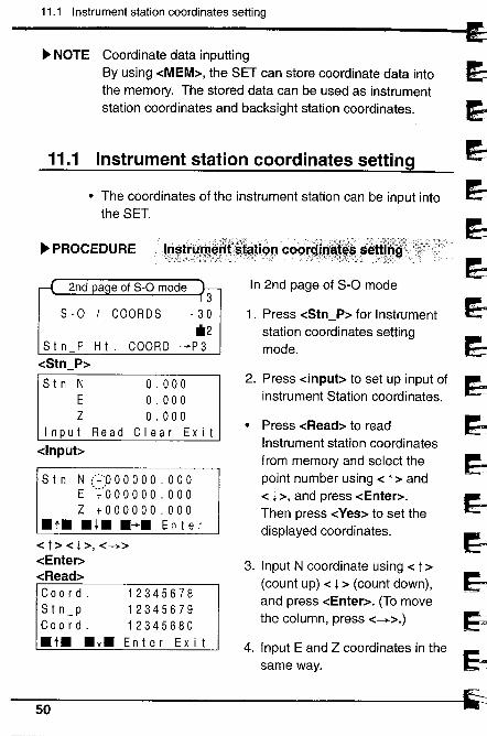
Coordinate data inputtingBy using -cMEM~, the SET can store coordinate data intothe memory. The stored data can be used as instrumentstation coordinates and backsight station coordinates.
~ NOTE
11.1~~rrrr~~~2. ~:~m~~~~::t:~n'~~~:~~~:,cn lr1
~~~~~
4. Inpul E and Z cooro;nale, ;n Ihe :1,ame way. ~
--
Instrument station coordinates setting
· The coordinates of the instrument station can be input intothe SET.
~ PROCEDURE lristrl.m~df'!~~tiôn""co()idi!---::::;:,\,r:;) /):\tY?i::::~\£,::' :\~-: ':.' .:\\:\:-,:----'-::Ji:. _ :':~::,,-'.,(r;y)"
a e of s-o mode3
- 30*2
..p 3
8-0 / COORD8
8 t n P H t .-cStn_P~
8 t n NE
Z
Input Read
-clnpub
COORD
o . 000o . 000o . 000
Clear Exit
S t n N (+':0 0 0 0 0 0 . 0 0 0E ',¡:OOOOOO.OOO
Z +000000.000.t. .l. .~. Enter
-c t ~ -c l ~, -c_~-cEnter~-cRead~Co 0 rd.
S t n_pCo 0 rd..t. .l.
123456781234567912345680Enter Exit
50
In 2nd page of S-O mode
1. Press -cStn_P~ for Instrumentstation coordinates settingmode.
· Press -cRead~ to read
Instrument station coordinatesfrom memory and select thepoint number using -c t ~ and-c l~, and press -cEnter~.Then press -cYes~ to set thedisplayed coordinates.
3. Input N coordinate using -c t ~
(count up) -c l ~ (count down),and press -cEnter~. (To movethe column, press -c_~.)
i
r3~~~~ .~r~~~~~.,"',";':~
~~~~-~
~'3" ,- .
~3
~3
~~
ç:j
11. COORDINATE MEASUREMENT
51
11.2 Target height and Instrument height setting
11.2 Target height and Instrument height setting
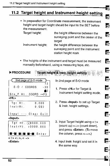
· In preparation for Coordinate measurement, the instrumentheight and target height should be input to the SET beforethe measurement.Target height:
Instrument height:
the height difference between thesurveying point and the center of thetargetthe height difference between thesurveying point and the instrumentstation height mark
· The heights of the instrument and target must be measuredmanually beforehand, using a measuring tape, etc.
~ PROCEDURE
8-0 I COORD81 3
- 30il2
-+P38 t n P H t. COORD
-cHt.~
T9 t H t .Ins t r H t .
o . 000o. 000
Input -.. Clear Exit
-clnpubT 9 t H t . (.~:~O 0 0 0 . 0 0 0
InstrHt. +0000.000
. t. . l. .~. En t e r
-c t ~ -c l ~, -c_~-cEnter~
In 2nd page of S-O mode
1. Press -cHt.~ for Target &Instrument height setting mode.
2. Press -clnpub to set up Target& Instr. height settings.
3. Input Target height using -c t ~
(count up) -c l ~ (count down),and press -cEnter~. (To movethe column, press -c_~.)
4. Input Instr. height and set it inthe same way.
~~~~~~
1
~~
ir~Il!f~
~~lJ;JJ
~~'~
.11
52
~~~~L;'r-nìl
~¡;~!i(iì
F~~r=~~3==a
~3'"3'lK::: .t; -.
;=~
11. COORDINATE MEASUREMENT
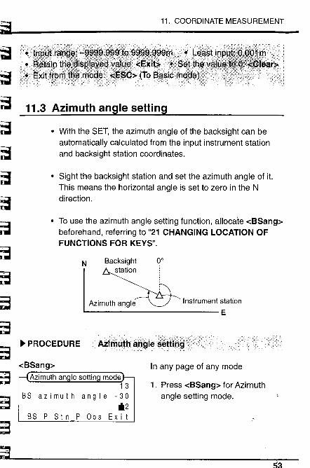
11.3 Azimuth angle settng
· With the SET, the azimuth angle of the backsight can beautomatically calculated from the input instrument stationand backsight station coordinates.
. Sight the backsight station and set the azimuth angle of it.This means the horizontal angle is set to zero in the Ndirection.
. To use the azimuth angle setting function, allocate -cBSang~beforehand, referring to "21 CHANGING LOCATION OFFUNCTIONS FOR KEYS".
N Backsightstation
00
Instrument station
EAzimuth angle
. PROCEDURE
In any page of any modemode
1 3
BS azimuth angle -30*2
BS P Stn P Obs Exit
1. Press -cBSang~ for Azimuthangle setting mode.
53
11.3 Azimuth angle setting
~~,.,'.",',
~)i
~~~.,~l',,',d-~
:i1~
dd
1
~~~~
-cBS_P~
BS NE
O. 000o . 000
Input Read Clear Exit-clnpub
B S N ::t'll 0 0 0 0 0 . 000E t'O 0 0 0 0 0 . 0 0 0
.t. .l. .~. Enter-c t ~ -c l ~, -c-+~-cEnter~
(-cRead~ )Co 0 rd.
Coo rd.
Co 0 rd.
.t. .l.
123456781234567912345680Enter Exit
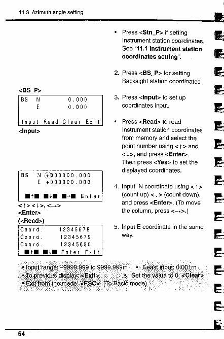
· Press -cStn_P~ if settingInstrument station coordinates.See "11.1 Instrument station
coordinates setting".
2. Press -cBS_P~ for settingBacksight station coordinates
3. Press -clnpub to set upcoordinates input.
· Press -cRead~ to read
Instrument station coordinatesfrom memory and select thepoint number using -c t ~ and-c l ~, and press -cEnter~.Then press -cYes~ to set thedisplayed coordinates.
4. Input N coordinate using -c t ~
(count up) -c l ~ (count down),and press -cEnter~. (To movethe column, press -c-+~.)
5. Input E coordinate in the sameway.
54
~~.".';.-'I'.~.'I
"r--
11. COORDINATE MEASUREMENT
~3~.~..-.~_.i-
~i
L....~.--: .-
~i~::'3-:'T
;".'.~" .;;
~3
~3-.'...~..,-;
~3
~3
~
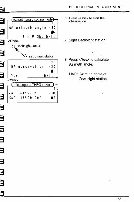
BS
6. Press -:Obs;: to start theobservation.
7. Sight Backsight station.
8. Press -cYes~ to calcUIp.teAzimuth angle.
HAR: Azimuth angle ofBacksight station
Stn P Obs-cObs~
o Sacksight station
~ Instrument station
1 3
BS observation -30*2
Ex i t
a e ofTHEO mode1 3
ZA 81°59'20" -30HAR 45°00'00" *2
~
11.4 3-Dimensional coordinate measurement
11.4 3-Dimensional coordinate measurement
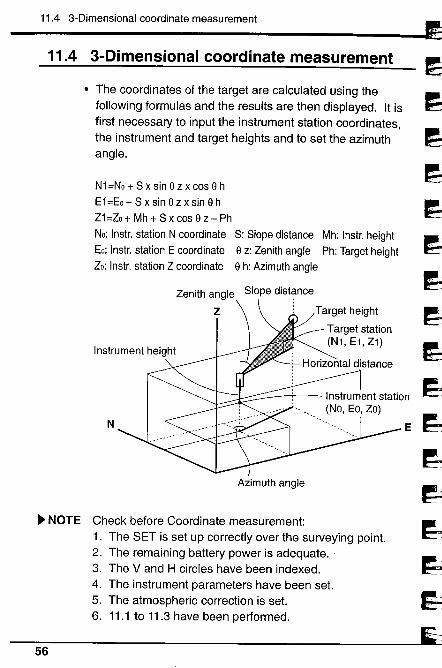
· The coordinates of the target are calculated using thefollowing formulas and the results are then displayed. It isfirst necessary to input the instrument station coordinates,the instrument and target heights and to set the azimuthangle.
N1=No + S x sin e z x cos e h
E1=Eo + S x sin e z x sin e h
Z1 =Zo + Mh + S x cos e z - Ph
No: Instr. station N coordinate S: Slope distance Mh: Instr. height
Eo: Instr. station E coordinate e z: Zenith angle Ph: Target height
Zo: Instr. station Z coordinate e h: Azimuth angle
Zenith angle
Z
Slope distance
Target height
~ Target station(Ni, El,Zl)
N
Azimuth angle
~ NOTE Check before Coordinate measurement:1. The SET is set up correctly over the surveying point.2. The remaining battery power is adequate. '3. The V and H circles have been indexed.4. The instrument parameters have been set.5. The atmospheric correction is set.6. 11.1 to 11.3 have been performed.
56
I
~~5~~~~31~
E ~d~
i~~~
l
~

~~~ ~ PROCEDURE
11. COORDINATE MEASUREMENT
~.~.'...~ ~ --i
~~~'~
~~,~'.'..rr- - (l
'",~-.~,~r ....
'"
~-~J;
~~~l''f~S~
;-~
~"':3- 1._,_
~3i".~.3..~..
~
Co()r~iii~tt: ri
~etInstrument station
a e of S-O mode1 3
- 30il2
-+P 3
1. Sight the target.
In 2nd page of S-O mode
2. Press -cCOORD~ to startCoordinate measurement.
3. Press -cSTOP~ to stop themeasurement.
.'. .T()rt~~~Ür$th$;héxt tår~~t;pdlntY~H§~k.,t~~ at. tìèlgn#
~--~---
57
S-O / COORDS
S i n P H t. COORD-cCOORD~
..__._...................nn... .:..C_ ~.?,~ .~_ ~. ,~, ~_~, _~__!
1 3
- 30
il2
N
E
Z
STOP-cSTOP~
1234,5641234.564
1 . 234
1 3
- 30
il2
58
.,~~5'J." ~.~
~~iJ.~diJd~~~
. m J
l~~r~~~~~".,;;, Tiil
~'~."
' '01
~~~-:.nI
~":i:i
~,~
~~~
w="::~¡:;;
h~~
Advanced measurement functions
12. RESECTION MEASUREMENT ....................... 61
13. MISSING LINE MEASUREMENT .................... 6613.1 Measuring the distance between 2 or more points ....... 6713.2 Changing the starting position ..................................... 69
14. SETTING-OUT MEASUREMENT .................... 7014.1 Distance setting-out measurement.................................... 7114.2 Coordinates setting-out measurement........................ 7414.3 REM setting-out measurement ..................................... 77
15. OFFSET MEASUREMENT ............................ 7815.1 Distance offset ............................................................... 7915.2 Angle offset ................................................................... 81
16. REM MEASUREMENT ............................... 83
S9-
60
~~~~.~p. L-i
~,J~~~~~~~~~J
j,-~~i
j~.c~t--8,
~t3
t3
f3~-;:
~i''~~¡ii;r-.:
~~''l
~~4..~rrll
~'~kC.~--.
~~",,~
¡q~"J/
l'-"'~"'..
::~io"'..
~.-i~.
12. RESECTION MEASUREMENT
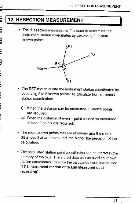
/12. RESECTION MEASUREMENT I. The "Resection measurement" is used to determine the
instrument station coordinates by observing 2 or moreknown points.
P4
P2
P3
· The SET can calculate the instrument station coordinates byobserving 2 to 5 known points. To calculate the instrumentstation coordinates:
CD When the distance can be measured, 2 known pointsare required.
æ When the distance of even 1 point cannot be measured,at least 3 points are required.
. The more known points that are observed and the moredistances that are measured, the higher the precision of thecalculation.
. The calculated station point coordinates can be stored in the
memory of the SET. The stored data can be used as knownstation coordinates. To store the calculated coordinates, see"17.3 Instrument station data and Measured datarecording".
61
12. RESECTION MEASUREMENT
~ PROCEDURE~),,':" .", ~
~í~~ri~d~i;dd~~..H~~
Elr
~'~ 1
S -0 / COORDS
ME M RES E C ..S H V
-cRESE~P 1 N
E
Z
I n put
o . 0000.0000.000
Read Clear OK
-clnpubP1 N +000000.000
E +000000.000Z +000000.000
. t. . t. .~. En t e r
-c t ~-c l ~-c_~-cEnter~
-cRead~Stn-P 00000002Stn-P 00000003Stn-P 00000004.t. Enter Exit
-c t ~-c l ~-cEnter~
P 1 N 3.000E 2.000Z 1 .000
Yes No
-cYes~
';;!~:;t:::::~-r~'f
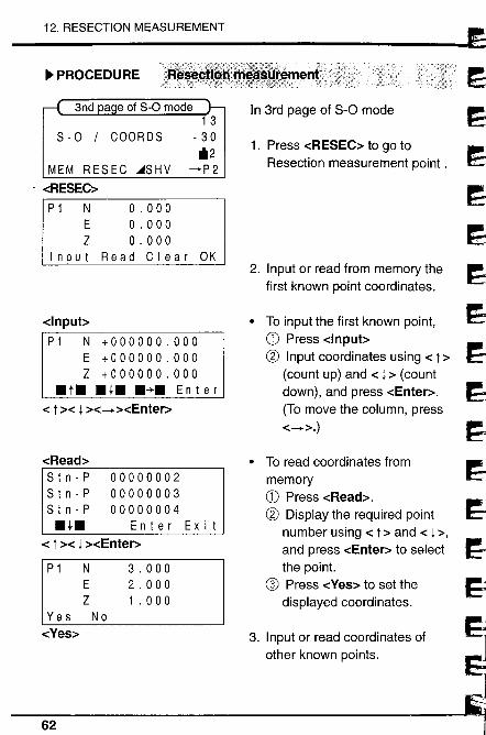
In 3rd page of S-O mode
1. Press -cRESEC~ to go toResection measurement point.
2. Input or read from memory thefirst known point coordinates.
· To input the first known point,CD Press -cnpub(g Input coordinates using -c t ~
(count up) and -c l ~ (countdown), and press -cEnter~.
(To move the column, press-c_~.)
· To read coordinates from
memoryCD Press -cRead~.(g Display the required point
number using -c t ~ and -c l ~,and press -cEnter~ to selectthe point.
o Press -cYes~ to set the
displayed coordinates.
3. Input or read coordinates ofother known points.
62
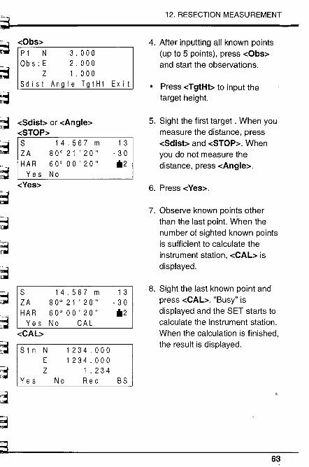
~~
12. RESECTION MEASUREMENT
-cObs~
, ~ .~.:~
P 1 N 3 . 000Ob s : E 2 . 000
Z 1 . 000S d i s t An 9 I e T 9 i H t Ex i t
4. After inputting all known points
(up to 5 points), press -cObs~and start the observations.
. Press -cTgtHb to input the
target height.
5. Sight the first target. When youmeasure the distance, press-cSdisb and -cSTOP~. Whenyou do not measure thedistance, press -cAngle~.
6. Press -cYes~.
7. Observe known points otherthan the last point. When thenumber of sighted known pointsis sufficient to calculate theinstrument station, -cCAL~ isdisplayed.
8. Sight the last known point andpress -cCAL~. "Busy" isdisplayed and the SET starts tocalculate the instrument station.When the calculation is finished,the result is displayed.
~~b.;...~IT~
~r-
-cSdisb or -cAngle~
-cSTOP~S 14.567 m 13ZA 80° 21 ' 20 " - 30HAR 60° 00 ' 20 " "2
Yes No
-cYes~
,
;~~..~
~~
~h;"r iLlil
S
ZA
HAR
Yes-cCAb
S t n NE
Z
..,";~ mil
"~~~~E~ Yes
l';;"';~
~3
æ
14.567 m80° 2 1 ' 20 "60° 00 ' 20 "No CAL
13- 30"2
1234,0001234.000
1 .234No Rec BS
63
12. RESECTION MEASUREMENT
· When the SET cannot find thesolution of the calculation, "nosolution" is displayed. You canselect whether to re-observefrom the first point (star! point)or only the last point.
. When a calculation error occurs,"Calculation error" is displayedand the screen returns to allowyou to input the known point.Input known point again.
· When the number of observedpoints is not sufficient forcalculation, ''Too few point" isdisplayed. Add (input) andobserve more points.
9. Press -cYes~ to confirm the
result.Press -cRec~ to record thestation point.
Press -cBS~ to set the azimuthangle of the known point to thelast known point.
.............................. ...................................................................................... ..... ........................ ...........................................................................................................................................
... ~..iÈQ.r,dßt~il~:~~Pl1t~BEP~,..s~è,,17.3.1n~i~ym~6t. iÌlgas~reddatarecording"!
í~l~~d
1~1
~64
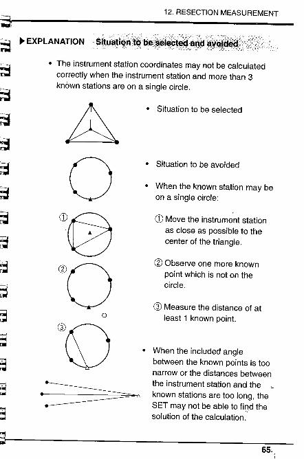
I
~F~b~l~r-r-S=
~~
~~~
12. RESECTION MEASUREMENT
~ EXPLANATION 'Si~4~Ji~~it~"li~~~i~St~~:::~ã&i~cij,;
~" :ni
e~~~ll
";=.' -'
"", mi
~"~
~,~'..
~,,3
,,~~
. The instrument station coordinates may not be calculated
correctly when the instrument station and more than 3knòwn stations are on a single circle.
&oW0
øoowo
.~ó
· Situation to be selected
· Situation to be avoided
· When the known station may beon a single circle:
G) Move the instrument stationas close as possible to thecenter of the triangle.
æ Observe one more known
point which is not on thecircle.
G) Measure the distance of atleast 1 known point.
· When the included anglebetween the known points is toonarrow or the distances betweenthe instrument station and theknown stations are too long, theSET may not be able to fil1d thesolution of the calculation.
65,
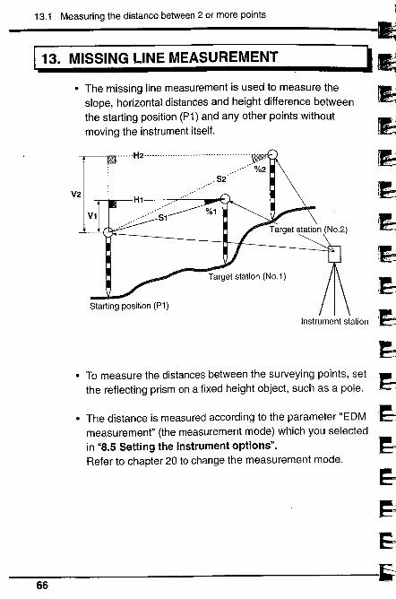
13.1 Measuring the distance between 2 or more points
113. MISSING LINE MEASUREMENT
. The missing line measurement is used to measure the
slope, horizontal distances and height difference betweenthe starting position (P1) and any other points withoutmoving the instrument itself.
V2
.....H2..........,.................,............, ,
V1
,S2
H1
Starting position (P1)
Instrument station
. To measure the distances between the surveying points, setthe reflecting prism on a fixed height object, such as a pole.
. The distance is measured according to the parameter "EDMmeasurement" (the measurement mode) which you selectedin "8.5 Setting the instrument options".Refer to chapter 20 to change the measurement mode.
66
I
~~~~'1~.~~,iJiJd~
1
.IJ1;-
~1
~
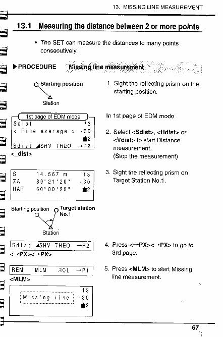
l~~....tS~~S~
13. MISSING LINE MEASUREMENT
~iri-~~r-~~-!..
~~~
~~~,,=i~~
13.1 Measuring the distance between 2 or more points
· The SET can measure the distances to many pointsconsecutively.
~ PROCEDUR EMis~jf!~i'j!'~i#~ÉΧij;rØ~fÎiit"
~ing position
Station
1st a e of EDM modeS d i s i 1 3~ Fine average ~ -30
*2Sd i s t ~SHV THEO ~P2
-c_disb
S 14.567 m 13ZA 80021'20" -30H A R 600 00 ' 20 " *2
Starting ptttion ? Target station"- No.1
Station
I S d i s t ~S H V THE 0 ~ P 2 I-c-PX~-cPX~
MLM ~P1 I
1. Sight the reflecting prism on thestarting position.
In 1 st page of EDM mode
2. Select -cSdisb, -cHdist~ or
-cVdist~ to start Distancemeasurement.(Stop the measurement)
3. Sight the reflecting prism onTarget Station NO.1.
4. Press -c-PX~-cPX~ to go to3rd page.
5. Press -cMLM~ to start Missingline measurement.
S ¡REM~;:: -cMLM~Ir~
as
RCL
1 3
:::~:~:~:~::~:~:~.:::i::i~:~::j . 30
*2
67,
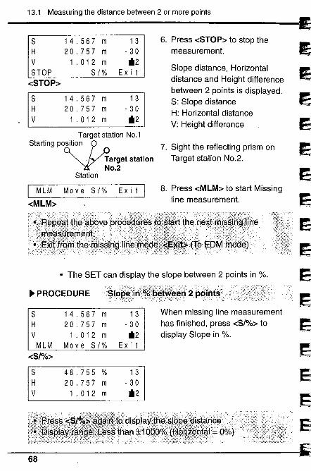
13.1 Measuring the distance between 2 or more points
S 14 . 567 m 13 6. Press -cSTOP~ to stop theH 20.757 m - 30 measurement.V 1 . 01 2 m il2STOP S /% Ex i t Slope distance, Horizontal
-cSTOP~ distance and Height difference
S 14 . 567 13between 2 points is displayed.
m S: Slope distanceH 20.757 m .30 H: Horizontal distanceV 1 . 01 2 m il2 V: Height difference
Target station No.1
Starting PO~ition ,
Target stationNo.2
Station
I M L M Move S / % Ex i t I-cMLM~
7. Sight the reflecting prism onTarget station NO.2.
8. Press -cMLM~ to star! Missingline measurement.
· The SET can display the slope between 2 points in %.
~ PROCEDURESlq~il1
When missing line measurementhas finished, press -cS/%~ todisplay Slope in %.
S
H
V
MLM
-cS/%~
14.567 m20.757 m1 .012 m
Move S/%
13- 30il2
Ex i t
S
H
V
48.755%20.757 m1 .012 m
13- 30il2
68
~~~~",~J~
~:i:i~
~. 1
~
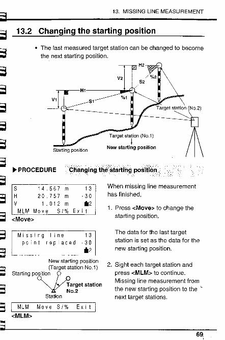
"",,7:-, -,",,~~,:'?~'~~~~r:~~~~~:?-~\~:'--"'~
~~ 13.2
~~~~~~~
~ PROCEDuREÇiiä~gingthê~täft¡Ôg posmSi:
~~~-;S
~13
~:=~ ~(-
~3
~3
~3 I MLM Mo v e 8/% Ex i t I-cMLM~
S3
13. MISSING LINE MEASUREMENT
Changing the starting position
· The last measured target station can be changed to becomethe next starting position.
V1
Starting position
8 14.567 mH 20.757 mV 1 .012 mMLM Move 8/%
-cMove:-
13.30il2
Ex i t
When missing line measurementhas finished,
1. Press -cMove~ to change thestarting position.
Missing line 13point replaced -30
il2
The data for the last targetstation is set as the data for thenew starting position.
New starting position(Target station No.1)
Starting PO~iiion
Target stationNo.2
Station
2. Sight each target station andpress -cMLM~ to continue.Missing line measurement fromthe new starting position to thenext target stations.
69,
14.1 Distance setting-out measurement
/14. SETTING-OUT MEASUREMENT
· The Setting-out measurement is used to set out the requiredpoint.The difference between the previously input data to theinstrument (the setting-out data) and the measured valuecan be displayed by measuring the horizontal angle,horizontal distance (-cSO_Hd~), coordinates (-cCoord~). orheight (-cSO_Hb) of the sighted point.
Setting out mode (-cS-O~)-c3D_SO~ ~ -cSO_Xd~ Distance setting-out
-cCoord~ Coordinate setting-out-cSO_Hb REM Setting-out
Displayed value
== Difference between measured value and setting-out data
· The distance is measured according to the parameter "EDMmeasurement" (the measurement mode) and Trackingmeasurement mode selection.
70
I
~~I!l~~~¡~¡~
iJ~l~l~J'~'_.'
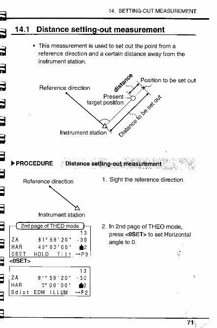
~~'!~6"~¡~~~~~Tt~~?l~'fl,~~7~
~~¡
~,'.'.~!íl i-
~,~
~.,-~' BI
~..c~r -1I
u
~~"~~~'~
~,~
~~~~~
~~
"3,,' .." ~i, -
14. SETTING-OUT MEASUREMENT
14.1 Distance settng-out measurement
· This measurement is used to set out the point from areference direction and a certain distance away from theinstrument station.
ú0~'bt:
&-t:
Presenttarget position
~~o0°
'Q0,0r-0~
'0-'lQ'"
~ PROCEDURE Disltince sètt!iÎg~oiilff~~~(Ír~,lTétlt.\Y'";',/:;,;( v
Reference direction
~1. Sight the reference direction.
Instrument station
ZA
HAR
OSET-cOSET~
a e of THEO mode13
- 30*2
-+P3
2. In 2nd page of THEO mode,press -cOSET~ to set Horizontalangle to O.
81°59'20"45°00'00"
HOLD T i i t
1 3
ZA 81°59'20" - 30HAR 0° 00 '00" *2S d i s t EDM I L LUM -+P 2
~7L

14.1 Distance setting-out measurement
~'1~;~
1
~.~.1j~~l~~~rd~1
~~
1
:J
Direction to beReference dir~ction set out
,...........
.. ....
Instrument station
-cESC~
Basic modePress functionkeys to selectoperation
EDM THEO S-O
13.30il2
CONF
13- 30il2
-+P 2
S-O / COORDS
SO 3 D 8 - 0 P 8 - 0 D-cS-O _D~
Distance S-O data settin mode
8-0 distanceO. 000
In ut Clear Exit-clnpub
8-0 distance+0000.000
. t. . l. .~. E n t e r
-c t ~ -c l ~ and -c_~-cEnter~
3
- 30il2
-+P 2
ZA 90°21 '40"HAR 45°53'20"80 3 D 8 - 0 P 8 - 0 D
3. Turn the theodolite until arequired angle is shown on thedisplay.
4. Press -cESC~ to go to Basicmode.
5. Press -cS-O~ go to S-O mode.
6. Press -cS-O_D~ for DistanceS-O data setting mode.
7. Input Distance S-O data.Press -clnpub and inputhorizontal distance S-O datausing -c t ~ (count up) and -c l ~
(count down). (-c_~ is to go tonext column.)Then press -cEnter~.
8. Set the reflecting prism on thesighting line and sight itcorrectly.
72
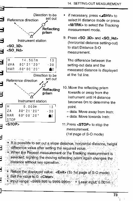
°Jt ii*PQ~R.iq!~tÒ 'SE3t2.LJtaRIQPe~iS1apC~1hori.Zohtal. distårìcè,.height
.~.i~~xar-.?e.y~lue~ft~rsettingthe re~uir~?vaI~e.. ..... ." .... ..: ..........
...7~q~ntß.~ft;~p~at . rie~surementQrthE3iT raCK¡n~.riE3aaur~ri~ri.tis
i:sel~bt~~;Figry;Vrig.the '.lToving .ra~lëpting príßIT:again. changes the;~i.~t?rice Vfith(:ytkE3y' cipt3 ration,
~t;3
Direction to beReference dir~ection set out
.,"" Reflecting" prism
':
Instrument station-cSO_3D~-cSO_Hd~
14, SETTING-OUT MEASUREMENT
o If necessary, press -c~SHV~ to
select H distance mode or press-cM/TRK~ to select the Trackingmeasurement mode.
9. Press -cSO_3D~ and -cSO_Hd~
(horizontal distance setting-out)to star! Distance S-Omeasurement.
The difference between thesetting-out data and themeasured distance is displayedat the 1 st line.
10. Move the reflecting prismtowards or away from theinstrument until H distancebecomes Om to determine thepoint.
- data: Move away from Instr.+ data: Move towards Instr.
11 . Press -cSTOP~ to stop the
measurement.(1st page of S-O mode)
~..;;~~~-,;;
~3~;.;=:
'!~~t~iR;th~~~iFpJ?y.èf J~IH~:'" -cE~it~(Taist.pagèofs-9mqga)
m!j:!S~tt~~val~:e..tQ'Q:...'S.CI~;ar~;:;,."';;; .....i. ....................:;..d,~
~.:h'p~WJr.~ri~W""9999¡999t()9999 .~,~9rr.;. ~.~l,eai-tini?pt:Ø.OQ1rn
S:,3
H 14.567m 13dHA 80021'20" .30HAR 600 00' 20" il2
Direction to beR f d. t' set oute e~::ce ire~c ion /:
", Reflecting", prism
Instrument stationH O.OOOm 13ZA 80021'20" -30HAR 600 00' 20" il2STOP
-cSTOP~
s;1
t3~"~
3~~3
~8:3
;;)'
73
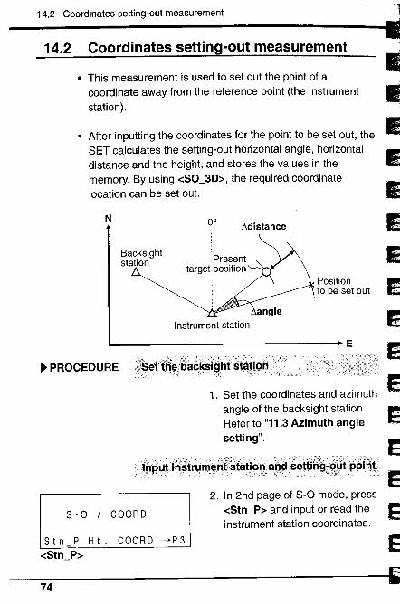
:\,:' ::_ __- ::_':':'_: :,::)::\:'.:'::::i::_'__'- 'c:::'; ::,-:':::,. .:-i;-\5'f;:.',:'-'----:-::,'- :,,:::,'. ,_,,'- .:_ _--: :'!:::':Y:!::,":,,_"_):;--;'_' '- - "",,~:y:;:, -'- --;:::-ri)::';.~_':_-___;:;¡:::':::;J:i_:;,,' ,:....I...!l.:........pU./ .t ..il'~trl.mellti~statipllanç1s~ttiÍig7c:Øt póiÔ!.:
c'.'- ::'" ':_:-- - ,:::; :::' -:: :'__' ,,'::',,:: - -'--,:';';~:--,'___\',-,:_:__ ,:,~:, \;.':' '- ___ ,,'_'.: ',:' , ~- ,-;;;Xj;~:':_ ---_::- -"" ..,--,
0° Lldistance
14.2 Coordinates setting-out measurement
14.2 Coordinates setting-out measurement
. This measurement is used to set out the point of acoordinate away from the reference point (the instrumentstation).
. After inputting the coordinates for the point to be set out, the
SET calculates the setting-out horizontal angle, horizontaldistance and the height, and stores the values in thememory. By using -cSO_3D~, the required coordinatelocation can be set out.
N
Backsightstation
Positionto be set out
~ PROCEDURE
1. Set the coordinates and azimuthangle of the backsight stationRefer to "11.3 Azimuth anglesetting".
S - 0 / COOR D
2. In 2nd page of S-O mode, press-cStn_P~ and input or read theinstrument station coordinates.
S t n P H t. COORD -+P 3
-cStn_P~
74n~
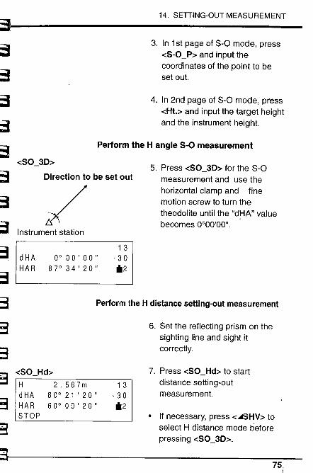
S:~~~.".-.;
~~~~~,,'~'l-
~~:3:.~ -;;:
~3~3::,'~-.~t:
14. SETTING-OUT MEASUREMENT
3. In 1 st page of 8-0 mode, press-cS-O_P~ and input thecoordinates of the point to beset out.
4. In 2nd page of S-O mode, press-cHt.~ and input the target heightand the instrument height.
Perform the H angle S-O measurement
-cSO_3D~
Direction to be set out
/Instrument station
13dHA 0°00'00" -30HAR 87°34'20" il2
5. Press -cSO_3D~ for the S-Omeasurement and use thehorizontal clamp and finemotion screw to turn thetheodolite until the "dHA" valuebecomes 0°00'00".
Perform the H distance setting-out measurement
-cSO_Hd~
H 2.567mdHA 80° 21' 20"HAR 60°00'20"STOP
13.30il2
6. Set the reflecting prism on thesighting line and sight itcorrectly.
7. Press -cSO Hd~ to startdistance setting-outmeasurement.
· If necessary, press -c..SHV~ toselect H distance mode beforepressing -cSO_3D~.
75,i
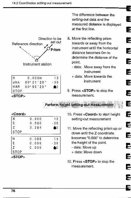
14.2 Coordinates setting-out measurement
Direction to be
R f d. t' set oute e~~nce Ire7c ion /. .
"-,, Prism"-
"-"-
"-"-
Instrument station
H
dHAHAR
STOP-cSTOP~
-cCoord~N
E
Z
STOP
N
E
Z
STOP-cSTOP~
o . 00 Om800 21' 20"60000'20"
13- 30il2
The difference between thesetting-out data and themeasured distance is displayedat the first line.
8. Move the reflecting prismtowards or away from theinstrument until the horizontaldistance becomes Om todetermine the distance of thepoint.- data: Move away from the
instrument+ data: Move towards the
instrument
9. Press -cSTOP~ to stop themeasurement.
10. Press -cCoord~ to star! heightsetting-out measurement
11. Move the reflecting prism up ordown until the Z coordinatebecomes "0.000" to determinethe height of the point.- data: Move up+ data: Move down
12. Press -cSTOP~ to stop themeasurement.
~76
Perfoftr
o . 000o . 0003.284
1 3
- 30il2
o . 000o . 000o . 000
13- 30il2
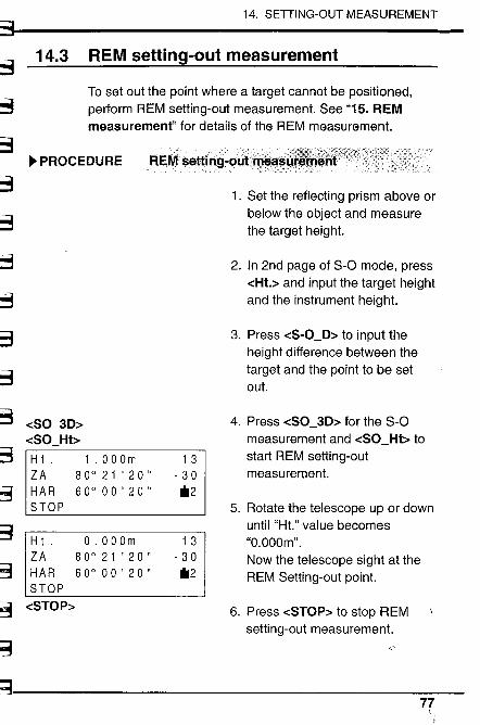
;:~.,..~~~~~~
14. SETTING-OUT MEASUREMENT
14.3 REM setting-out measurement
To set out the point where a target cannot be positioned,perform REM setting-out measurement. See "15. REMmeasurement" for details of the REM measurement.
~ PROCEDURE FlEMsettil1g-øLJt'ff~ä~; ....,
~~~,~ -cSO_3D~
-cSO_Hb~~~
~g
~3
:i3 -cSTOP~
H t . 1 .00 Om 13ZA 80° 21' 20" .30HAR 60°00'20" 112STOP
H t ' O.OOOm 13ZA 80° 21' 20" - 30HAR 60° 00 ' 20 " 112
STOP
~;;~
~
1. Set the reflecting prism above orbelow the object and measurethe target height.
2. In 2nd page of S-O mode, press-cHt.~ and input the target heightand the instrument height.
3. Press -cS-O_D~ to input theheight difference between thetarget and the point to be setout.
4. Press -cSO_3D~ for the S-Omeasurement and -cSO_Hb tostart REM setting-outmeasurement.
5. Rotate the telescope up or downuntil "Ht." value becomes"O.OOOm".
Now the telescope sight at theREM Setting-out point.
6. Press -cSTOP~ to stop REMsetting-out measurement.
77
15.1 Distance offset J
115. O~::~ m:=::~::::~~ measuffe d;smnce de ~ 3
angle to a point which cannot be sighted or where the target . 1
cannot be positioned. ~Set the offset point (a point near the target point) and input" l'the distance between the target point and the offset point 5(distance offset) or set the angle between the target point "and the offset point (angle offset). Then measure the offsetpoint. The SET calculates the distance and the angle of the ~.target point. _J
-i-i-i9~..1J
· ~~~:i~~~~:~~~~~eo~::~~:'~;~:~h::a~;et he;ght of the 9
~1
~J1
j~~~¡
i
There are 2 methods of offset measurement
CD Distance offset· When the offset point is positioned to the right or left of the
target point, set it so the angle formed by lines connectingthe target point to the offset point and to the station pointis approximately 90°.
· When the offset point is in front of or behind the targetpoint, set it on the sighting line from the station point tothe target point.
æ Angle offset
. Install the offset point as close as possible to the targetpoint to its left or right.
78
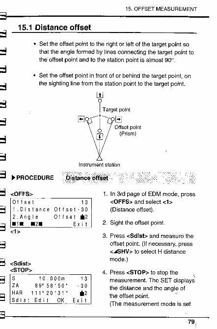
15. OFFSET MEASUREMENT
::1t;; 15.1 Distance offset
~ · Set the offset point to the right or left of the target point sothat the angle formed by lines connecting the target point tothe- offset point and to the station point is almost 90°.~
. Set the offset point in front of or behind the target point, onthe sighting line from the station point to the target point.~
~ w
f Target point
(. EJOffset point
(Prism)
~ 8
;::~~~~
~~~3
Instrument station
~ PROCEDURE
1 3
Offset-30Off set *2
Ex i t
1. In 3rd page of EDM mode, press-cOFFS~ and select -c1 ~
(Distance offset).
2. Sight the offset point.
-cOFFS~Off set
1.Distance2.Angle.1. .2.-ch
3. Press -cSdisb and measure theoffset point. (If necessary, press-c..SHV~ to select H distancemode.)~.~ -cSdisb
-cSTOP~ 4. Press -cSTOP~ to stop the,
measurement. The SET displaysthe distance and the angle ofthe offset point. C(The measurement mode is set
§,:g
B2:
S 10.000m 13ZA 89°58'50" - 30HAR 111 ° 20 ' 31 " *2Sd i s t Ed i t OK Ex i t
79.
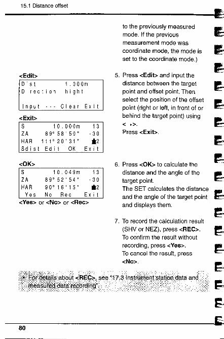
15.1 Distance offset
~
~~
1
ì9ì~dd~~d~
-cEdibD is tDirection
1 .00 Om
h i 9 h t
I n put
-cExit~
Clear Exit
S 10.000m 1 3
ZA 89°58'50" - 30HAR 11 1 ° 20 ' 31 " *2S d i s t Ed i t OK Ex i t
-cOK~
S 10.049m 13ZA 89°52'54" -30HAR 90°16'15" *2Yes No Rec Exit
-cYes~ or -cNo~ or -cRec~
to the previously measuredmode. If the previousmeasurement mode wascoordinate mode, the mode isset to the coordinate mode.)
5. Press -cEdib and input thedistance between the targetpoint and offset point. Thenselect the position of the offsetpoint (right or left, in front of orbehind the target point) using-c_~.Press -cExib.
6. Press -cOK~ to calculate thedistance and the angle of thetarget point.
The SET calculates the distanceand the angle of the target pointand displays them.
7. To record the calculation result
(SHV or NEZ), press -cREC~.To confirm the result withoutrecording, press -cYes~.
To cancel the result, press-cNo~.
80
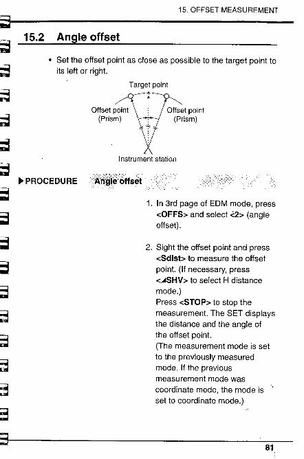
~~~~~~~~~~~,',,~~ "-i
~~~,;~ ...
~~
~.~
~ :;"'~
15. OFFSET MEASUREMENT
s
15.2 Angle offset
· Set the offset point as close as possible to the target point toits left or right.
Offset point
(Prism)
~ PROCEDURE ::;Ao~;Î~:6ffsêt
Target point+.
Offset point
(Prism)
Instrument station
1. In 3rd page of EDM mode, press-cOFFS~ and select ..2~ (angleoffset) .
2. Sight the offset point and press-cSdisb to measure the offsetpoint. (If necessary, press-CASHV~ to select H distancemode.)Press -cSTOP~ to stop themeasurement. The SET displaysthe distance and the angle ofthe offset point.
(The measurement mode is setto the previously measuredmode. If the previousmeasurement mode wascoordinate mode, the mode isset to coordinate mode.)
81..
15.2 Angle offset
3. Sight the target point using the
Horizontal clamp and theHorizontal fine motion screw.
4. Press -cOK~ to calculate thedistance and the angle of thetarget point.
The SET calculates the distanceand the angle of the target pointand displays them.
5. To record the calculation result,press -cREC~.To confirm the result withoutrecording, press -cYes~.
To cancel the result, press-cNo~.
82
i¡ i
i'ik
~~.....l.i..
.1t
mi'~
~llJi
~i'1. J..
íl.~p,'... I.~ '
~~:-~
~~~
I ~~""CC~
') l.. '~"J"~~~Ji '
i i
~
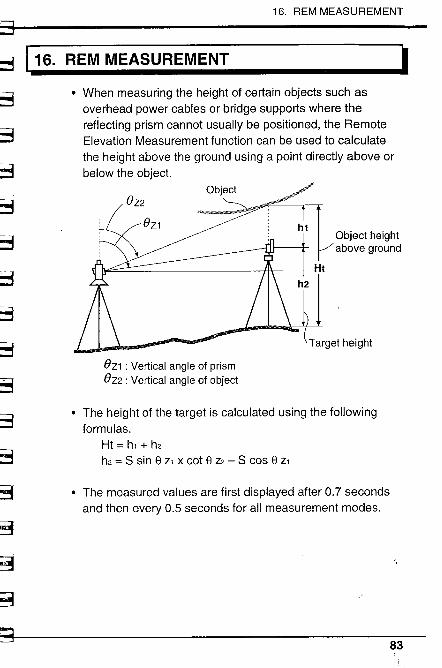
16. REM MEASUREMENT
~::~u:: 116. REM MEASUREMENT
~~~~~
~;.::
;'8~
~-3
~;~~~3k=3~
~3
~3
~:~
: :3
~
I· When measuring the height of certain objects such as
overhead power cables or bridge supports where thereflecting prism cannot usually be positioned, the RemoteElevation Measurement function can be used to calculatethe height above the ground using a point directly above orbelow the object.
h1Object height
above ground
Ht
h2
Target height
eZ1 : Vertical angle of prismeZ2 : Vertical angle of object
· The height of the target is calculated using the followingformulas.
Ht = h, + h2
h2 = S sin El z, x cot El Z2 - S cos El z,
. The measured values are first displayed after 0.7 secondsand then every 0.5 seconds for all measurement modes.
83
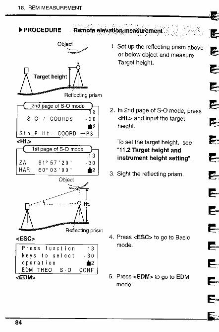
16. REM MEASUREMENT
~ PROCEDURE:__. ,0':,,_ ._____' _ .;.r' ,__", _ ,",'- :,'"(-,-/--',,:'--'--,-:-, ':'," ': ~,.-:,' - ----,._' '/',:, "",~'::,,~-';, ".:/~, .:,'_:
Flerriøtg.~.I~Vatlon:irnea$ùÍ'gmgnt.
3 2. In 2nd page of S-O mode, pressS .0 / COORDS - 30 -cHt.~ and input the target
il2 height.H t . COORD -+P 3
To set the target height, see"11.2 Target height and
1 3 instrument height setting".ZA 91°57'20" - 30HAR 60° 03' 00" il2
3. Sight the reflecting prism.
Object
Object~
Reflecting prism
-cESC~
Press function 13keys to select -30ope rat ion il2EDM THEO S - 0 CONF
-cEDM~
1. Set up the reflecting prism aboveor below object and measureTarget height.
4. Press -cESC~ to go to Basicmode.
5. Press -cEDM~ to go to EDMmode.
~'ï'ï'ï~,ft~
1
~E=
~1~~~EJ~,
'-I84
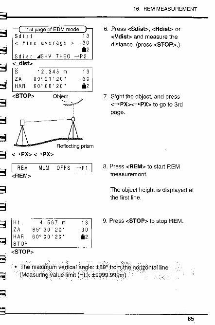
:=b3~~~~~~ -;:
b3
~~-3
~~~~
~g
~3
~g
~.g
~
16, REM MEASUREMENT
1st a e of EDM modeS d i s t 1 3~ Fine average ~ -30
*2Sd i s t ~SHV THEO -P2
-c_disbS 12.345 m 13ZA 80°21'20" ,30H A R 60° 00 ' 20 " *2
-cSTOP:-
Æ
Object~iL
6. Press -cSdisb, -cHdisb or-cVdisb and measure thedistance. (press -cSTOP~.)
7. Sight the object, and press-c-PX~-c-".pX~ to go to 3rdpage.
8. Press -cREM~ to star! REMmeasurement.
The object height is displayed atthe first line.
9. Press -cSTOP~ to stop REM.
· TheniaXimi9~ VßAicalanQle: :t89¿frårTf,t8~h~rj~bhtalline
" (Measurin~M;:Jyelimit (igt;):::9~~~,99grD)
..Reflecting prism
c:-PX~ -cPX~
I REM MLM OFFS -P1 I-cREM~
H i . 4,567 m 1 3
ZA 65° 30' 20" - 30HAR 60° 00 ' 20 " *2STOP
-cSTOP~
85.
86
~~~
~ .~~~IJ~ï~l~d
1
~~--
~1
~
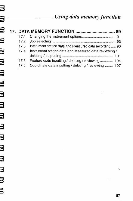
~r
~r'-t-~r~~~~~~~-WJ
;,~ ;;
.'3~=-i .
~3',- ,
;,,3.., -
~;3
;c;3
-.ß!~
Using data memory function
17. DATA MEMORY FUNCTION ............................. 8917.1 'Changing the instrument options................................. 9117.2 Job selecting ............................................................... 9217.3 Instrument station data and Measured data recording ..... 9317.4 Instrument station data and Measured data reviewing /
deleting / outputting ................................................... 10117.5 Feature code inputting / deleting / reviewing ............. 10417.6 Coordinate data inputting / deleting / reviewing ........ 107
87

88
~'.'
~~1Id
5~~~~~~~
1~1
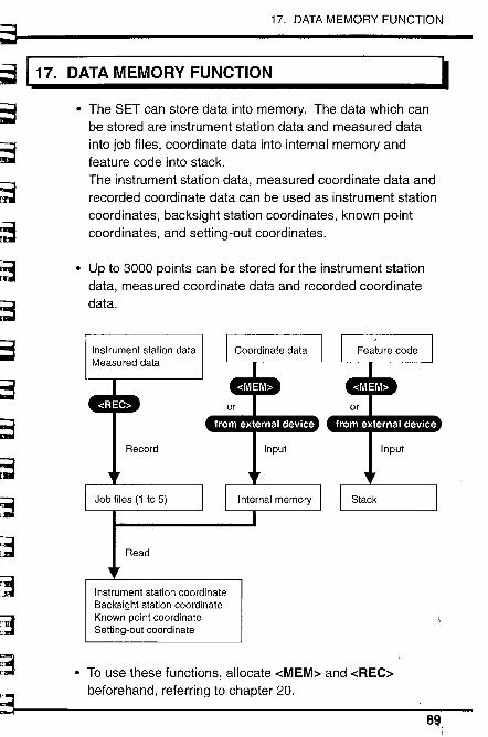
~~I~~~~c~
~~=
~~
~3
~~~~'~
~~
§~
""3l!'_I:'- L
8
17. DATA MEMORY FUNCTION
,17. DATA MEMORY FUNCTION
. The SET can store data into memory. The data which canbe stored are instrument station data and measured datainto job files, coordinate data into internal memory andfeature code into stack.The instrument station data, measured coordinate data andrecorded coordinate data can be used as instrument stationcoordinates, backsight station coordinates, known pointcoordinates, and setting-out coordinates.
. Up to 3000 points can be stored for the instrument stationdata, measured coordinate data and recorded coordinatedata.
Instrument station dataMeasured data
Record
Job files (1 to 5)
Read
Instrument station coordinateBacksight station coordinateKnown point coordinateSetting-out coordinate
. To use these functions, allocate -cMEM~ and -cREC~beforehand, referring to chapter 20.
89,
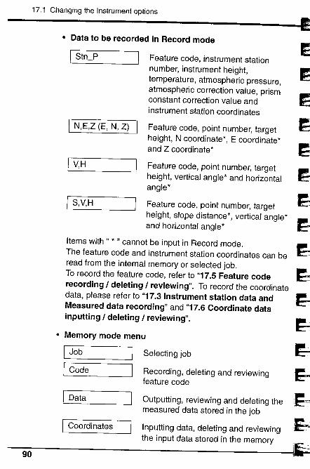
17.1 Changing the Instrument options
· Data to be recorded in Record mode
I Stn_P Feature code, instrument stationnumber, instrument height,
~temperature, atmospheric pressure,atmospheric correction value, prismconstant correction value and
~instrument station coordinates
I N,E,Z (E, N, Z) IFeature code, point number, target 5height, N coordinate', E coordinate'and Z coordinate' ~
I V,H Feature code, point number, target
~height, vertical angle' and horizontalangle'
I S,V,H Feature code, point number, target ~height, slope distance', vertical angle'and horizontal angle'
~Items with" . " cannot be input in Record mode.The feature code and instrument station coordinates can be ~read from the internal memory or selected job.To record the feature code, refer to "17.5 Feature code
~recording / deleting / reviewing". To record the coordinate
data, please refer to "17.3 Instrument station data and
~Measured data recording" and "17.6 Coordinate datainputting / deleting / reviewing".
~· Memory mode menu ~I Job Selecting job
~ICode Recording, deleting and reviewing
feature code
,~I
Data Outputting, reviewing and deleting themeasured data stored in the job ~Coordinates Inputting data, deleting and reviewing
~the input data stored in the memory
90 I.'
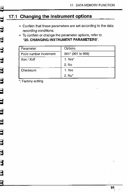
-,": ~'-;'''-~;~'f,.~:_ß'..'._~Srft''.-::~~~'-"'''~--~ ,-. ~~~~~~~~=
~~~ '.
~~~~~~=
~~-,iD
;a
17. DATA MEMORY FUNCTION
17.1 Changing the Instrument options
. Confirm that these parameters are set according to the data
recording conditions.. To confirm or change the parameter options, refer to
"20. CHANGING INSTRUMENT PARAMETERS".
Parameter Options
Point number increment 001' (001 to 999)
Xon I Xoff 1. Yes'
2. No
Checksum 1. Yes
2. No'
': Factory setting
91
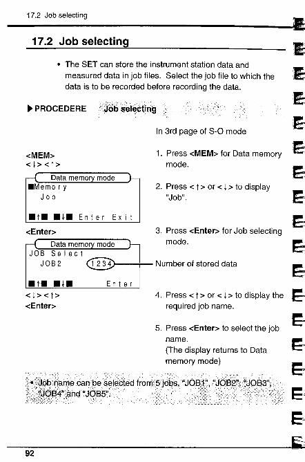
17.2 Job selecting
17.2 Job selecting
· The SET can store the instrument station data andmeasured data in job files. Select the job file to which thedata is to be recorded before recording the data.
~ PROCEDERE\i¡)()bselectil1g
-cMEM~-c l ~ -c t ~
Data memo.Memo r y
Job
.t..i.Enter Exit
-cEnter~
Data memoJOB Select
JOB 2
.t. .i.-c l ~ -c t ~
-cEnter~
En t e r
In 3rd page of S-O mode
1. Press -cMEM~ for Data memorymode.
2. Press -c t ~ or -c l ~ to display"Job".
3. Press -cEnter~ for Job selectingmode.
Number of stored data
4. Press -c t ~ or -c l ~ to display therequired job name.
5. Press -cEnter~ to select the jobname.(The display returns to Datamemory mode)
.OO.U"__"__ _ __ __ ___"
§..'~.(l~ßcan~es~i~êted, fro~5)d~s,JW.?I"ç1 ~JQB5".
~.Ej
.E)~
..JJEJ~~~~~E;,,,
~1
:J92
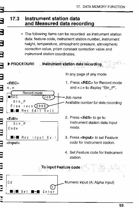
=i~~e3
~
17. DATA MEMORY FUNCTION
17.3 Instrument station dataand Measured data recording
· The following items can be recorded as instrument stationdata: feature code, instrument station number, instrumentheight, temperature, atmospheric pressure, atmosphericcorrection value, prism constant correction value andinstrument station coordinates.
~'3 ~ PROCEDUREInstrÜffknt~tåti(sh dåta'l'~tótd¡O~f
t3~¡¡ ;;
~r6.,..;-,~~i
-cREC~-c ¡~
.RECS t n P
Free recs 2989.i. Rec Edit Exit
"3~r -!' U
-cEdibS t n P
Cod e3~ -cnput~':!lJ
.i. Rec Input Exit
a..r~~~'i-
..n~~",,.Cd
¡.lJ~
E:
In any page of any mode
1. Press -cREC~ for Record modeand -c ¡ ~ to display "Stn_P".
Job nameAvailable number for data recording
2. Press -cEdib to go toInstrument station data inputmode.
3. Press -clnpub to set Featurecode for Instrument station.
4. Set Feature code for Instrument
station.
¡' Toinpl.tFetltul'~code.
.i. S e I ....
"¡~~
Numeric input (A: Alpha input)
93
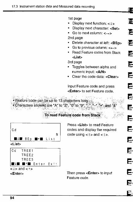
17.3 Instrument station data and Measured data recording
1 st page
· Display next function: -c l ~· Display next character: -cSel~· Go to next column: -c-+~2nd page· Delete character at left: -cBSp~· Go to previous column: -c+-~· Read Feature codes from Stack
o:List~
3rd page· Toggles between alpha and
numeric input: -cA/N~· Clear the code data: -cClear~
Input Feature code and press-cEnter~ to set Feature code.
'~
,:)!:)
~~~~~~~~i;i~l,
..E~âfUretQcløc .:-:;'. ~,,:,y..;0:'-.:, _ :::"...__:__-:, -_. '_,: :',-\"oJ:"_....Çharaçteirsáiid
/;¡t6'):eádFéáttitéb~déf~orij.Sta~ìt;.' . ':, ':" : ,~::':". :: ' ",? ',.' " '-" -. -- , ,- --"- "'-': .:,':' ,,-,"
CdN
.-1. BS P .~. Lis t-cLisb
Cd TREE1TREE 2TREE3
.-1. .t. Enter Exit-c l ~ and -c t ::-cEnter~
Press -cLisb to read Featurecodes and display the requiredcode using -c t ~ and -c l ~.
Then press -cEnter~ to inputFeature code,
94
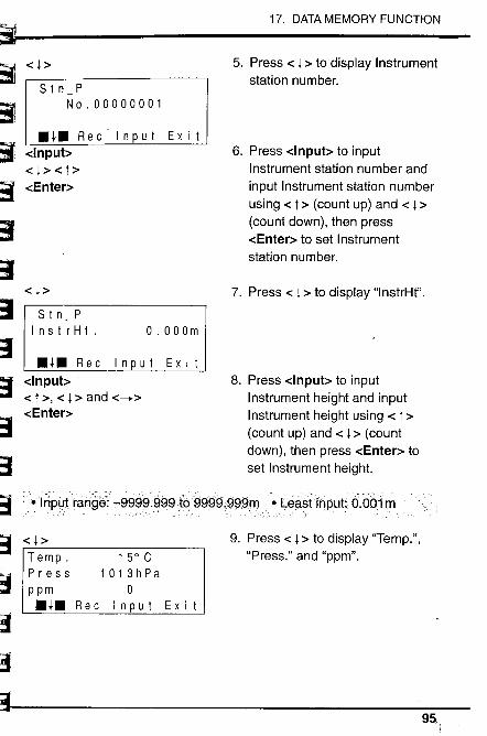
~~f'
17. DATA MEMORY FUNCTION
-c l ~
S t n PNo.00000001
5. Press -c l ~ to display Instrumentstation number.
6. Press -clnpub to inputInstrument station number andinput Instrument station numberusing -c t ~ (count up) and -c l ~
(count down), then press-cEnter~ to set Instrumentstation number.
7. Press -c l ~ to display "lnstrHt".
8. Press dnpub to inputInstrument height and inputInstrument height using -c t ~
(count up) and -c l ~ (countdown), then press -cEnter~ toset Instrument height.
.lnPLJlrahgé:,-99g~.999t()999g.~99m. · téa-stinput: Ô.ÔÔÙn
9. Press -c l ~ to display "Temp.","Press." and "ppm".
.l. Rec'lnput Exi t-clnput::-c l~ -ct~-cEnter~
~S t n P
Ins t r H t . o . 00 Om
.l. Rec Input Exit-clnpub-c t ~, -c l ~ and -c__~-cEnter~
sSI'j
ß~~;:
S -c l ~
Temp. 15°CPress 1013hPap pm 0.l.Rec Input Exit
t;~;;:;
~~~l-~~
;-:;h"::
895
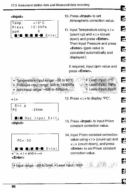
17.3 Instrument station data and Measured data recording J
~~~~'l~;J
1~j~)
'l~1
9~)
~..)
î9~
dnput~
Temp. +15°CPress 1013hPap pm 0.t. .l. .~. Enter
10. Press -clnput~ to setAtmospheric correction value.
11. Input Temperature using -c t ~
(count up) and -c l ~ (countdown) and press -cEnter~.Then input Pressure and press-cEnter~ (ppm value iscalculated automatically anddisplayed.)
If required, input ppm value andpress -cEnter~.
-c l ~ 12. Press -c l ~ to display "PC".
S t n_ p
PC -30mm
.l. Rec Input Exit-clnput~
PC=-30
. t. . l. .~. E n t e r
-c t ~, -c l ~ and -c__~-cEnter~
13. Press -clnpub to input Prismconstant correction value.
14. Input Prism constant correctionvalue using -c t ~ (count up) and-c l ~ (count down), and press-cEnter~ to set Prism constantcorrection value.
--s~¡JBhnim ..pLeast.¡rihuEi.mJll
96
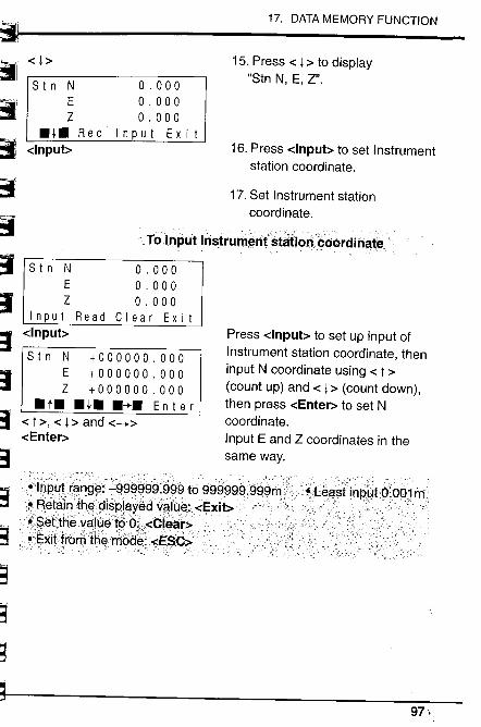
-c l ~
17. DATA MEMORY FUNCTION
15. Press -c l ~ to display
"Stn N, E, Z".
16. Press -clnpub to set Instrumentstation coordinate.
17. Set Instrument stationcoordinate.
Tolnput Instrum~nfstätioni:()òrdihøtê
Press -clnpub to set up input ofInstrument station coordinate, theninput N coordinate using -c t ~
(count up) and -c l ~ (count down),then press -cEnter~ to set Ncoordinate.Input E and Z coordinates in thesame way.
~""C,;, i!r 'S t n N o . 000
E o . 000Z o . 000
..¡. R e c I n put Ex i t~d -u:,'
. ,"
~:3~C
-clnpub
S t n N o . 000E o . 000Z o . 000
I n put Rea d C I ear Ex i t-clnput~
St n N +000000.000E +000000.000Z +000000.000
.t. ..¡. .~. Enter-c t~, -c l ~ and -c-+~-cEnter~
:.:1¡¡;3~Ìf .St3J1'Ë3
~~
97\.
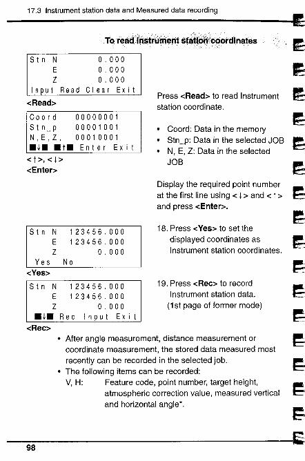
17.3 Instrument station data and Measured data recording
,TC) rêådl'n~t~ûìt~nt. st~tfØ~i~~øÌ'dlhat~s
o. 000o . 000o . 000
Clear Exit
S t n NE
Z
Input Read
-cRead~
Coord 00000001Stn_p 00001001N,E,Z, 00010001.l. .t. Enter Ex i t
Press -cRead~ to read Instrumentstation coordinate.
· Coord: Data in the memory· Stn_p: Data in the selected JOB· N, E, Z: Data in the selected
JOB-c t;:, -c l ~
-cEnter~
Display the required point numberat the first line using -c l ~ and -c t ~and press -cEnter~.
18. Press -cYes~ to set thedisplayed coordinates as
Instrument station coordinates.
S t n NE
Z
Yes-cYes~
Stn N 123456.000E 123456.000Z 0.000
.l.Rec Input Exit-cRec~
123456.000123456.000
0.000No
19. Press -cRec~ to recordInstrument station data.
(1st page of former mode)
· After angle measurement, distance measurement orcoordinate measurement, the stored data measured mostrecently can be recorded in the selected job.
· The following items can be recorded:V, H: Feature code, point number, target height,
atmospheric correction value, measured verticaland horizontal angle'.
98
3~~~d
)~dd~3
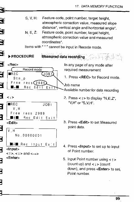
~ .
~~~~
~b..,.~I
l~
~~t ~-3i.ft
17. DATA MEMORY FUNCTION
S, V, H: Feature code, point number, target height,
atmospheric correction value, measured slopedistance', vertical angle and horizontal angle'.
N, E, Z: Feature code, point number, target height,
atmospheric correction value and measuredcoordinates'.
Items with" , " cannot be input in Recode mode.
-cRec~
~ PROCEDURE
-c l ~
IIå.as4rec:f cllitarecc)Ì';llng
In any page of any mode afterrequired measurement
1. Press -cREC~ for Record mode.
Job nameAvailable number for data recording
JOB 1
2. Press -c l ~ to display "N,E,Z","V,H" or "S,V,H"..REC
V, H
F r e e.l.-cEdib
recs 2989Rec Edit Exit
3. Press -cEdib to set Measuredpoint data.
V, H
No.00000001
:;;iWf~~
.l. R e c I n put Ex i i
-clnpub-c t ~, -c l ~ and -c-+~-cEnter~
4. Press -clnpub to set up to inputof Point number.
~3r'31""-,~
,.~." -,-
~
5. Input Point number using -c t ~
(count up) and -c l ~ (countdown), and press -cEnter~ to set,Point number.
99-
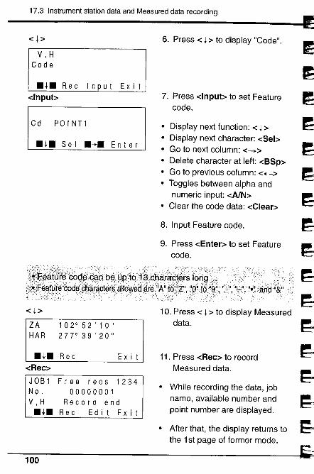
17.3 Instrument station data and Measured data recording
-c l ~
V, H
Co d e
.l. Rec Input Exit-clnpub
Cd POINT1
.l. S e I .~. En i e r
6. Press -c l ~ to display "Code".
7. Press -clnpub to set Featurecode.
· Display next function: -c l ~· Display next character: -cSel~
. Go to next column: -c_~
. Delete character at left: -cBSp~· Go to previous column: -c+-~· Toggles between alpha and
numeric input: -cAlN~· Clear the code data: -cClear~
8. Input Feature code.
9. Press -cEnter~ to set Featurecode.
dd
1
í~1~1
~~~~~~.~
~
-c l ~
ZA 102°52'10"HAR 277°39'20"
.l. Rec-cRec~
Ex i t
JOB 1No.V, H.l.
Free recs 123400000001
Record endRec Edit Exit
10. Press -c l ~ to display Measureddata.
11. Press -cRec~ to recordMeasured data.
· While recording the data, jobname, available number andpoint number are displayed.
· After that, the display returns tothe 1 st page of former mode.
100
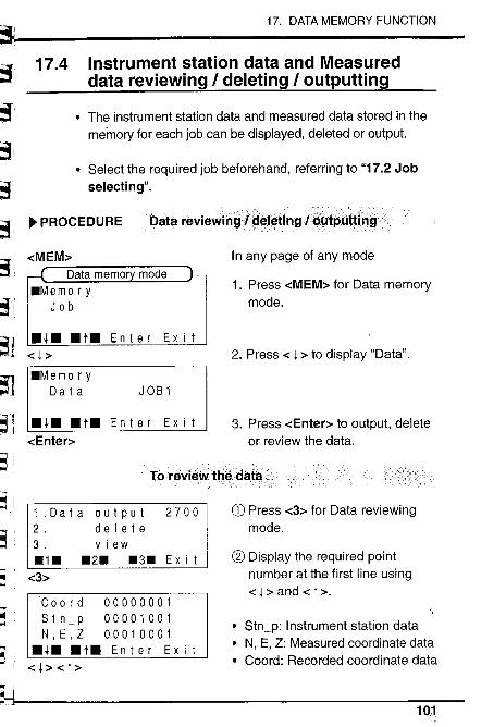
fi~;~
~'~i
~:~;
17. DATA MEMORY FUNCTION
~
~w.
¡:i
I:i:,~l¡~
17.4 Instrument station data and Measureddata reviewing I deleting I outputting
. The instrument station data and measured data stored in thememory for each job can be displayed, deleted or output.
. Select the required job beforehand, referring to "17.2 Jobselecting".
~ PROCEDURE Data. reviewirígì~~I~tîng Ig~tpÜtHij~i
-cMEM~
Data memo
.Memo r yJob
... .t. Enter Exit-c l ~
.Memo r yData JOB1
... . t. En t erE x i t
-cEnter~
In any page of any mode
1. Press -cMEM~ for Data memorymode.
2. Press -c l ~ to display "Data".
3. Press -cEnter~ to output, deleteor review the data.
'-.I
W-.. .~iTorEÌ\fiEÌwttiê.dafli, ,
~-~,
1 ,Da t a out put 27002. del e t e3. view.1. .2. .3. Ex i t
CD Press -c3~ for Data reviewing
mode.
æ Display the required pointnumber at the first line using-c l ~ and -c t~.
. Stn_p: Instrument station data
N, E, Z: Measured coordinate data. Coord: Recorded coordinate data
1i_-i~.. -c3~
~~-".
Coord 00000001Stn_p 00001001N,E,Z 00010001
... .t. Enter Exi t-c l ~ -c t~
,w...iir,"".,.j
i.. '""-1
(_I10,1
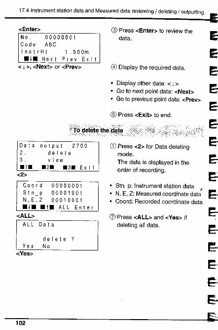
17.4 Instrument station data and Measured data reviewing / deleting / outputting
-cEnter~No. 00000001Code ABCInstrHt 1.500m.l. N ext Pre v Ex i t
-c l ~, -cNext;: or' -cPrev~
cr Press -cEnter~ to review the
data.
G) Display the required data.
· Display other data: -c l ;:· Go to next point data: -cNexb· Go to previous point data: -cPrev~
CI Press -cExib to end. ~~;J)!
~~~~
i~~~~
ll
5d, . j
Da t a2.3..1.
-c2~
output 2700del e t eview
.2. .3. Ex i t
Coord 00000001Stn_p 00001001N,E,Z 00010001.l. .t. ALL Enter
-cALbALL Data
Yes-cYes~
delete?No
CD Press -c2~ for Data deleting
mode.The data is displayed in theorder of recording.
· Stn_p: Instrument station data i
· N, E, Z: Measured coordinate data· Coord: Recorded coordinate data
æ Press -cALb and -cYes~ ifdeleting all data.
102
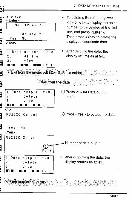
~J
~l~i~l1
~l
~~~J
~ri~'j
~~~S:3
:3
aa
17. DATA MEMORY FUNCTION
-c t ~ -c l ~-cEnter~
No. 12345678
Yes-cYes~
d e I,e t e ?No
· To delete a line of data, press-c t ~ or -c l ~ to display the pointnumber to be deleted at the firstline, and press -cEnter~.Then press -cYes~ to delete thedisplayed coordinate data.
· After deleting the data, thedisplay returns as at left.
-":._~:,_::::,:~- ':-:'.\:-:-' -.' __,.,___,.:/::;:,.-:-.,:- -/--:-.,"'- ;-:-'---, -: :-,-:" ':,;,,:\4" , :._-_,..",,~~_:,: ',' --c;':- -,'- .:.,'.:: ',:, - - ,,:). "., - '.,"-:.::''.;---. : /,:: ;:~
· Ex. ì..tfro.m................tbe m.. . O.d..........~. 5-C..'.1:.'. SC.. ;:....(.Ta13. ..as.ic. mOdd. S...).,..., ,. ,," -' '. --.(.T()~MtPLl~tliêdäiå ....
1.Data output 27002. delete3. view.1. .2. .3. Ex i t
-c1~
RS232C Output
Yes No-cYes~
RS232C Output
o
Ex i t
1.Data output 27002. delete3. view.1. .2. .3. Ex it
1.Data output 27002. delete3. view.1. .2. .3. Ex it
CD Press -c ~ for Data output
mode.
il Press -cYes~ to output the data.
Number of data output
. After outputting the data, the
display returns as at left.
103 '
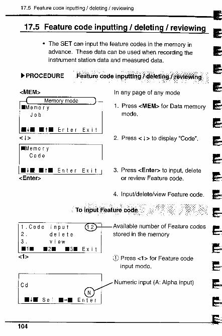
~~~~4. Inputdeletelview Feat"", code. ~
~Available number of Feature codes ,~_~sto'ed in the memmy l!J
~~.~~
17.5 Feature code inputting / deleting / reviewing
17.5 Feature code inputting I deleting I reviewing
· The SET can input the feature codes in the memory inadvance. These data can be used when recording theinstrument station data and measured data.
~ PROCEDURE F~.~HÙte. codei.n. p........"'. )1In."9....I...... a. '...'.d....èlet. i....n......'.',ø.. ì¡j~~ib... ¡gV.Fib.9;'~, ----- - - .,.,,: ,,', " ',' '.. - "
-cMEM~ In any page of any mode
1. Press -cMEM~ for Data memorymode.
.l. . t. En t erE x i t
-c l ~
.Memo r yCod e
2. Press -c l ~ to display "Code".
.l. .t. Enter Exit-cEnter~
3. Press -cEnter~ to input, deleteor review Feature code.
TQ
1.Code input 122. delete3. view.1. .2. .3. Ex it
-chCD Press -ch for Feature code
input mode.
Cd Numeric input (A: Alpha input)
.l. Se I .-+.
104
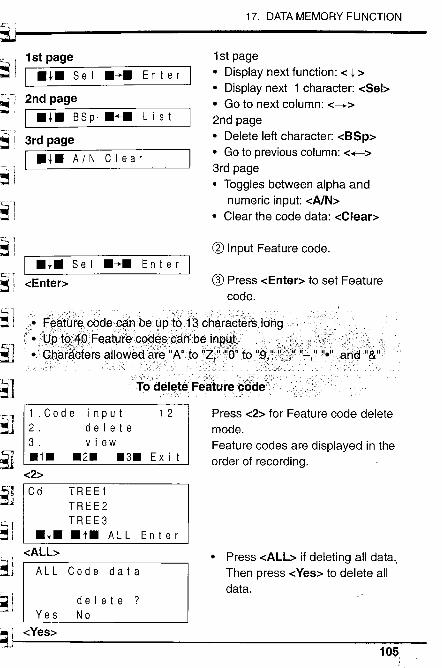
i¡~.~U ", HI 1st page
F' I.l.. S e I .... E n i e r
~I 2nd page!,: I.l.. BSp .... List
~" i 3rd page
; ,CC" I . l. . A / N C I ear~i
17. DATA MEMORY FUNCTION
,.s¡~j¡.:~')~l.i 'c.'l I.l.. S e I .... En t e r I
~ i -cEnter~
¡i I--l~J.:-
!l ci-'~j,ì
~',51Ii~j!', ,~
~ r~-l""l- ¡~-._.Lj
~l:~1i.-;
¡i'l"'1:'~j¡i~.- iÍI \ri j~i~ j
1 st pageo Display next function: -c l ~o Display next 1 character: -cSel~o Go to next column: -c-+~
2nd pageo Delete left character: -cBSp~o Go to previous column: -c+-~
3rd pageo Toggles between alpha and
numeric input: -cA/N~o Clear the code data: -cClear~
æ Input Feature code.
G) Press -cEnter~ to set Featurecode.
F~~t6r~90de,9~nb~ lJPt~ai;3chara.?térs lohg
°Ye . FaaturaC9 . cin:beinRYt.
o ' Ghì:rc ers alloWèd ,
T~del~tèi=e~Iureegde;::: .,
1.Code input 122. delete3. view.1. .2. .3. Ex it
-c2~
Cd TREE 1TREE2TREE3
.l.. .t. ALL-cALL~
ALL Code data
En t e r
Yes
SJ -cYes~
delete?No
Press -c2~ for Feature code deletemode.Feature codes are displayed in theorder of recording.
o Press -cALL~ if deleting all dataó,
Then press -cYes~ to delete alldata.
10S,
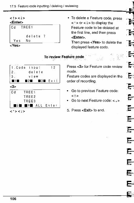
17.5 Feature code inputting I deleting I reviewing
-c t ~ -c l ~-cEnter~Cd TREE 1
Yes-cYes~
delete?No
· To delete a Feature code, press-c t ~ or -c l ~ to display theFeature code to be deleted atthe first line, and then press-cEnter~.Then press -cYes~ to delete thedisplayed feature code.
TClÌ'e"i~Vi Fei;tUÌ'eçaçle
1.Code input 122. delete3. view.1. .2. .3. Ex i t
-c3~
Cd TREE 1TREE2TREE3
.l. .t. ALL Enter-c t ~ -c l ~
Press -c3~ for Feature code reviewmode.Feature codes are displayed in theorder of recording.
· Go to previous Feature code:-c t~
· Go to next Feature code: -c l ~
5. Press -cExit~ to end.
~..~~~....'
"'1.,
,.
~,~iiE=~EJ~~~~106
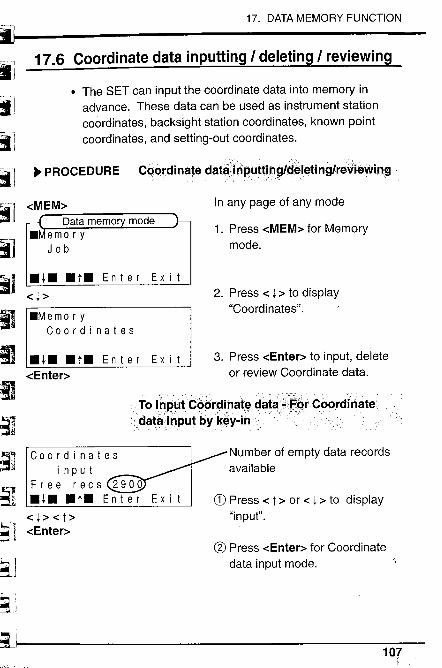
""
iiillil -
;ll~Iii c-.¡ ~ PROCEDURE
jl~I ~MEM,
~~ -c~~. .t. Enter Exit:1,' .Memo r y
1_ Coo r din ate s:g .l. .t. Enter Exit~ -cEnter~
L,
~ ~I'~t'__ 1 -cEnter~
i~l~i( J
i31~C
17. DATA MEMORY FUNCTION
17.6 Coordinate data inputting I deleting I reviewing
. The SET can input the coordinate data into memory inadvance. These data can be used as instrument stationcoordinates, backsight station coordinates, known pointcoordinates, and setting-out coordinates.
Ca(¡rdinate datå,¡ri~ptti.n~i~eleti nglre;jiewin~
In any page of any mode
Data memo.Memo r y
Job1. Press -cMEM~ for Memory
mode.
2. Press -c l ~ to display"Coordinates".
3. Press -cEnter~ to input, deleteor review Coordinate data.
To ililÌut.Còòr~inat~datå:'F§rCòordinate
. datainputbyk~y-in "
Coordinatesi n put
Free recs 2900.l. .t. Enter
Number of empty data recordsavailable
Ex i t CD Press -c t ~ or .: ¡ ~ to display"input".
æ Press -cEnter~ for Coordinate
data input mode.
107
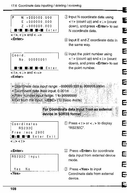
P N +000000.000 G) Input N coordinate data usingE +000000.000 -c t ~ (count up) and -c l ~ (countZ +000000.000 down), and press -cEnter~ to set
.t. .l. .-+. En t e r N coordinate data.-c t~, -c l~ and -c-+~-cEnter~ G) Input E and Z coordinate data in
~-.
the same way.
Co 0 rd. CI Input the point number using
No. 00000001 -c t ~ (count up) and -c l ~ (count
3
down), and press -cEnter~ to set.t. .l. .-+. En t e r the point number.
-c t ~, -c l ~ and -c-+~-cEnter~
eJ1
Eij
9Coordinates CD Press -c t ~ or -c l ~ to display ~
RS232C "RS232C" .
eJF r e e r e c s 2900.l. . t. En t e r Ex i t 11
-c l ~ -c t ~ j~CV Press -cEnter~ for coordinate
1-cEnter~ 11
RS232C I n put data input from external device
EJmode.
Yes No G) Press -cYes~ to input EJ-cYes~ Coordinate data from externalE1device.
5108
17.6 Coordinate data inputting / deleting / reviewing
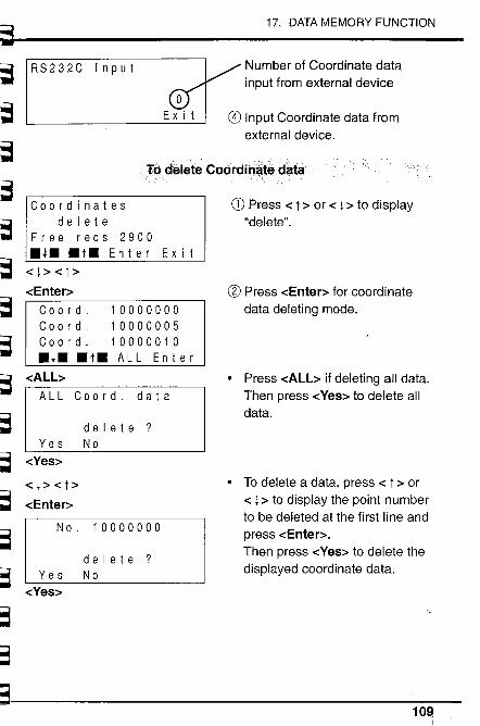
~~.~ R S 2 3 2 C I n put
17. DATA MEMORY FUNCTION
t:;=
~~~
Number of Coordinate datainput from external device
G) Input Coordinate data fromexternal device.
Tòdelete Coórdinatedatå
Coordinatesdel e t e
Free recs 2900..¡. .t. Enter Exit-c l~ -c t ~
-cEnter~Coord. 10000000Coord. 10000005Coord. 10000010.t. .t. ALL Enter
-cALbALL Coord. data
~,~
~~~~
~~~
~~
~~L-i
Yes-cYes~
-c l ~ -c t ~
-cEnter~
No.
delete?No
10000000
delete?No
CD Press -c t ~ or -c l ~ to display"delete".
æ Press -cEnter~ for coordinate
data deleting mode.
· Press -cALL~ if deleting all data.Then press -cYes~ to delete alldata.
. To delete a data, press -c t ~ or-c l ~ to display the point numberto be deleted at the first line andpress -cEnter~.
Then press -cYes~ to delete thedisplayed coordinate data.ir~-t. Yes
-cYes~
~.'. ;;"t._
~.~~~~~
s10~
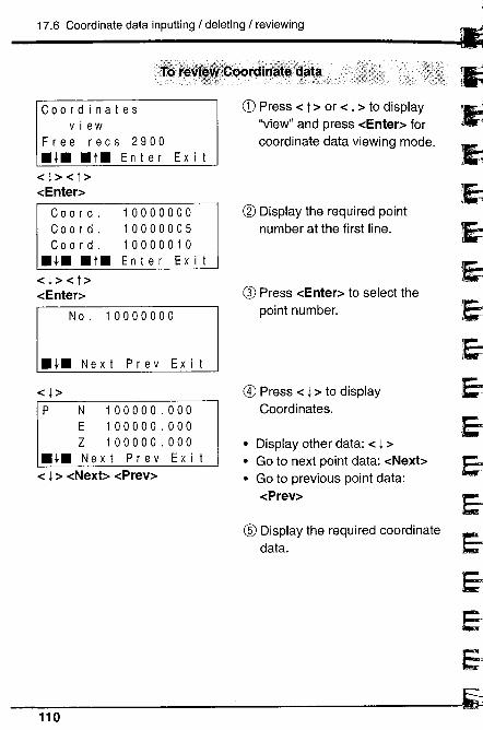
17.6 Coordinate data inputting / deleting / reviewing
Coordinatesview
Free recs 2900.l. .t. Enter Exit-c l~ -c t ~
-cEnter~
Coo rd.
Coo rd.
Co 0 rd.
..¡. .t.
100000001000000510000010Enter Exit
-c l ~ -c t ~-cEnter~
No. 10000000
.l. Next Prey Exit
-c l ~
P N 100000.000E 100000.000Z 100000.000
..¡. N ext Pre v Ex i t
-c l ~ -cNexb -cPrev~
CD Press -c t ~ or -c l ~ to display"view" and press -cEnter~ forcoordinate data viewing mode.
æ Display the required pointnumber at the first line.
G) Press -cEnter~ to select thepoint number.
G) Press -c l ~ to displayCoordinates.
· Display other data: -c l ~· Go to next point data: -cNexb· Go to previous point data:
-cPrev~
rI Display the required coordinate
data.
,i:: 1
~~E-ei'S)
S)~~
)~cJ
19~,
110
~Frrrr~~~3
~~~~3
~c3
. 3""lE'
~3
~B
~
Troubleshooting
18. ERROR MESSAGES ............................... 113
19. CHECKS AND ADJUSTMENTS ...................... 11619.1 Plate level .....................................................................11619.2 Circular level.................................................................11819.3 Tilt sensor ..................................................................... 11919.4 Reticle ......................................................................... 12319.5 Optical plummet .......................................................... 12819.6 Distance measurement check flow chart ..................... 13019.7 Additive distance constant ........................................... 131
111
112
~~~.,:e.-'.'
~J
';1
:l
~:itji=~~z;
J
Ej~i
Ei~
1
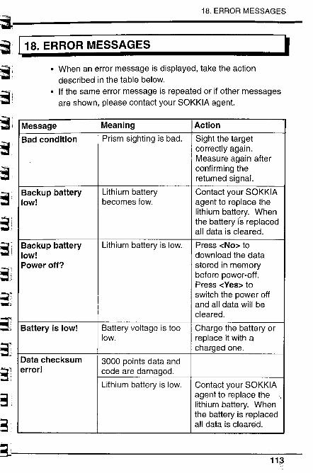
,,'~. -.. -~ - :
"L I~J~.d.:.'
r-- ;18.'",. '. - ",
~'L~:; ik'3-i-. '
~l~.:".i
i
(~:~-:3i.
b;~~l~i
~"3,(~3
~L
18. ERROR MESSAGES
I18. ERROR MESSAGES
. When an error message is displayed, take the actiondescribed in the table below.
. If the same error message is repeated or if other messagesare shown, please contact your SOKKIA agent.
Message Meaning Action
Bad condition Prism sighting is bad. Sight the targetcorrectly again.
Measure again afterconfirming thereturned signaL.
Backup battery Lithium battery Contact your SOKKIAlow! becomes low. agent to replace the
lithium battery. Whenthe battery is replacedall data is cleared.
Backup battery Lithium battery is low. Press -cNo~ tolow! download the dataPower off? stored in memory
before power-off.Press -cYes~ to
switch the power offand all data will becleared.
Battery is low! Battery voltage is too Charge the battery orlow. replace it with a
charged one.Data checksum 3000 points data anderror! code are damaged.
Lithium battery is low, Contact your SOKKIAagent to replace thelithium battery. Whenthe battery is replacedall data is cleared.
11¡3
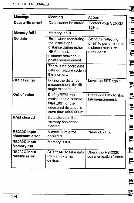
18. ERROR MESSAGES
Message Meaning ActionData write error! Data cannot be stored. Contact your SOKKIA
agent.Memory full ! Memory is fulL.
No data Error when measuring Sight the reflectingthe initial slope prism to perform slopedistance during either distance measure-REM or horizontal ment again.distance between 2points measurement.
There is no coordinatedata or Feature code inthe memory.
Out of range During the distance Level the SET again.measurement, the tiltangle exceeds :t3'.
Out of value During REM, the Press -cSTOP~ to stopvertical angle is more the measurement.than :t89° or themeasured distance ismore than 9999.999m.
RAM cleared Data stored in thememory has beencleared.
RS232C input A checksum error Press -cEXIT~.
checksum error occurred.
RS232C input Memory is fulL.Memory full
RS232C input SET failed to take data Check the RS-232Creceive error from an external communication format.
device.
114
9~:d~'9199.~iJ.~.El_J
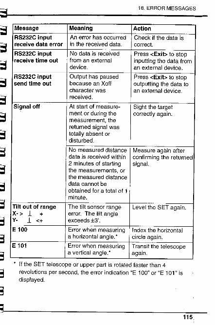
~~r=~~~t¡T"-
~~~~~~-I:i-
~~"3
~3
~;3
~3
~~
18. ERROR MESSAGES
Message Meaning Action
RS232C input An error has occurred Check if the data isreceive data error in the received data. co rrect.
RS232C inpLlt No data is received Press -cExib to stopreceive time out from an external inputting the data from
device. an external device.
RS232C input Output has paused Press -cExib to stopsend time out because an Xoff outputting the data to
character was an external device.received.
Signal off At start of measure- Sight the targetment or during the correctly again.measurement, thereturned signal wastotally absent ordisturbed.
No measured distance Measure again afterdata is received within confirming the returned2 minutes of starting signaL.the measurements, orthe measured distancedata cannot beobtained for a total of 1minute.
Til out of range The tilt sensor range Level the SET again.x- ~ l + error. The tilt angley- l -c+ exceeds :t3'.
E 100 Error when measuring Index the horizontala horizontal angle.* circle again.
E 101 Error when measuring Transit the telescopea vertical angle.* again.
* If the SET telescope or upper part is rotated faster than 4revolutions per second, the error indication "E 1 00" or "E 1 01" isdisplayed.
115
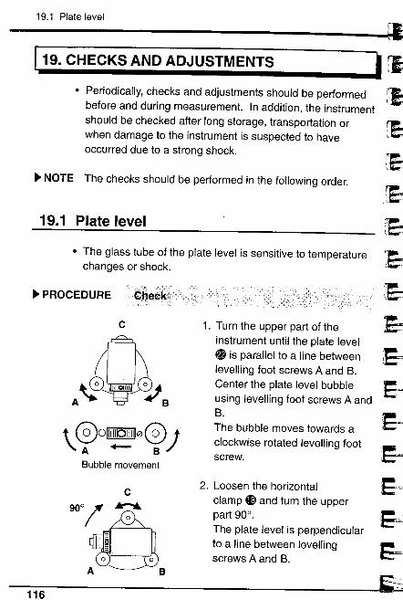
19.1 Plate level
119. CHECKS AND ADJUSTMENTS
. Periodically, checks and adjustments should be performedbefore and during measurement. In addition, the instrumentshould be checked after long storage, transportation orwhen damage to the instrument is suspected to haveoccurred due to a strong shock.
~ NOTE The checks should be performed in the following order.
19.1 Plate level
~~
~~'1-~
'J~:~~~~
i
.EJ~~
~
· The glass tube of the plate level is sensitive to temperaturechanges or shock.
~ PROCEDURE
c
t 001111101111100;
'A +- BBubble movement
c9001 ~
~A B
1. Turn the upper part of theinstrument until the plate level~ is parallel to a line betweenlevelling foot screws A and B.Center the plate level bubbleusing levelling foot screws A andB.
The bubble moves towards aclockwise rotated levelling footscrew.
2. Loosen the horizontalclamp Gi and turn the upperpart 900.
The plate level is perpendicularto a line between levellngscrews A and B.
116
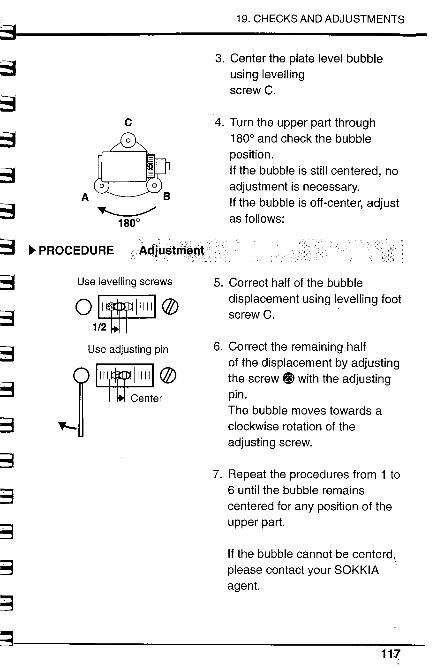
~~~t3~~~~;:-~~~~g
~~
~3
~~B
~'.'~
19. CHECKS AND ADJUSTMENTS
~~
~
c
.û~1800
~ PROCEDURE Adlostrñ~~t
3. Center the plate level bubbleusing levellingscrew C.
4. Turn the upper part through1800 and check the bubble
position.If the bubble is still centered, noadjustment is necessary.If the bubble is off-center, adjustas follows:
5. Correct half of the bubbledisplacement using levelling footscrew C. '
6. Correct the remaining halfof the displacement by adjustingthe screw ~ with the adjustingpin.The bubble moves towards aclockwise rotation of theadjusting screw.
7. Repeat the procedures from 1 to6 until the bubble remainscentered for any position of theupper part.
If the bubble cannot be centerd,please contact your SOKKIAagent.
11.-
Use levelling screwsO~ø1~Use adjusting pin
1~Ø~er~
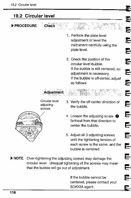
19.2 Circular level
19.2 Circular level
~ PROCEDURE
Ac:î'~~thi~nt
Circular leveladjustingscrews
1. Perform the plate leveladjustment or level theinstrument carefully using theplate leveL.
2. Check the position of thecircular level bubble.If the bubble is still centered, noadjustment is necessary.If the bubble is off-center, adjustas follows:
3. Verify the off-center direction of
the bubble.
4. Loosen the adjusting screw 0farthest from that direction tocenter the bubble.
5. Adjust all 3 adjusting screwsuntil the tightening tension ofeach screw is the same, and thebubble is centered.
~ NOTE Over-tightening the adjusting screws may damage thecircular leveL. Unequal tightening of the screws may meanthat the bubble will go out of adjustment.
If the bubble cannot becentered, please contact yourSOKKIA agent.
~~"
, d
,~1
~~,~~
~..
~
~~.l~~
)1~)~
~118
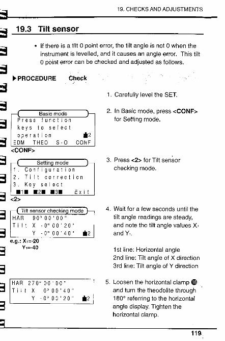
~~~~~~~~~
19. CHECKS AND ADJUSTMENTS
~:3
~-3
~1;;.. ,1;;
~,;::., ,;~::
~.::=~ ,~;:
~3
~;3
t,:.:~S
19.3 Tilt sensor
. If there is a tilt 0 point error, the tilt angle is not 0 when theinstrument is levelled, and it causes an angle error. This tilto point error can be checked and adjusted as follows.
~ PROCEDURE
Basic modePress functionkeys to selectoperation
EDM THEO 8-0-cCONF~
Tilt sensor checkinHAR 90°00'00"Tilt X -0°00'20"
Y -0°00'40"e.g.: X,=-20
Y,=-40
Check
*2CONF
Ex i t
*2
HAR 270°00'00"Till X 0°00'40"
Y -0°00'20" *2
1. Carefully level the SET.
2. In Basic mode, press -cCONF~for Setting mode.
3. Press -c2~ for Tilt sensorchecking mode.
4. Wait for a few seconds until thetilt angle readings are steady,and note the tilt angle values Xiand Yi.
1 st line: Horizontal angle2nd line: Tilt angle of X direction3rd line: Tilt angle of Y direction
5. Loosen the horizontal clamp 4Iand turn the theodolite through1800 referring to the horizontalangle display. Tighten thehorizontal clamp.
119.
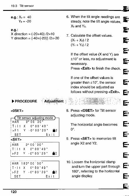
19.3 Tilt sensor
e.g.: X2 = 40Y2 = -20
e.g.:X direction = (-20+40) /2=10Y direction = (-40+(-20)) /2=-30
~ PROCEDURE A~jÛ$t~êiit'
-cOSET~
0°00'00"X 0°00'40"Y -0°00'20" 112
HAR 180° 00' 00"Tilt X 0°00'40";, F 2 Y - 0 ° 00 ' 20 " 112SET Exit
6. When the tilt angle readings aresteady, note the tilt angle values,X2 and Y2.
7. Calculate the offset values.
(Xi + X2) / 2
(Yl + Y2) / 2
If the offset value (X and Y) are:t10" or less, no adjustment isnecessary.Press -cExib to finish the check.
If one of the offset values isgreater than :t1 0", the sensorindex should be adjusted asfollows without pressing -cExib.
8. Press -cOSET~ for Tilt sensoradjusting mode.
The horizontal angle becomes0°.
9. Press -cSET~ to memorize tiltangle X2 and Y2.
10. Loosen the horizontal clampand turn the upper part through180°, referring to the horizontalangle display.
~~~........'.
..
, ,
~'9ErEJ'9EJ~EjEJ~eiï120
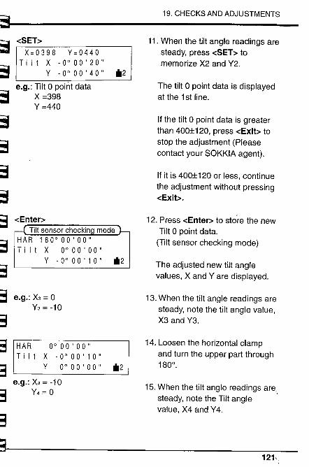
~ 19. CHECKS AND ADJUSTMENTS
~ -cSET~ 11. When the tilt angle readings areX~0398 Y~0440 steady, press -cSET:: to
~ Tilt X -0°00'20" memorize X2 and Y2.Y -0°00'40" 62
e.g.: Tilt 0 point data The tilt 0 point data is displayed~ X =398 at the 1 st line.Y =440
~ If the tilt 0 point data is greaterthan 400:1120, press -cExit~ to
~ stop the adjustment (Please.. contact your SOKKIA agent).
Ë: If it is 400:1120 or less, continueh- ~
~:!the adjustment without pressing
ry--i-cExib.
~ -cEnter~ 12. Press -cEnter~ to store the new""I
Tilt sensor checkin Tilt 0 point data.
&3HAR 180°00'00" (Tilt sensor checking mode)
1,, Tilt X 0°00'00"Y -0°00'10" 62 The adjusted new tilt angle
E3~, values, X and Yare displayed.
abri e.g.: X3 = 0 13. When the tilt angle readings areY3=-10 steady, note the tilt angle value,
~'3 X3 and Y3.0,,
~a HAR 0°00'00" 14. Loosen the horizontal clamp...
and turn the upper part throughT i It X -0°00'10"
8 Y 0° 00 ' 00 " 62 180°.
e.g.: X4 = -1015. When the tilt angle readings are,
""3Y4 = 0iir steady, note the Tilt angle'7:
value, X4 and Y4.
§3~.
~121,

19.3 Tilt sensor
e.g.:X direction = (0+(-10)) /2 = -5Y direction = (-10+0) /2 = -5
-cExib
Ex i t
16. Calculate the offset values.
(X3 + X4) / 2
(Y3+ Y4) / 2If the offset values (X and Y) are:t10" or less, the adjustment hasbeen finished.
17. Press -cExib to finish thecheck.
(Setting mode)
If one of the offset values aregreater than :t1 0", repeat theadjustment procedures.
." ",frclritti$:m~~~;,-tE)è.¡.(~..d ,?iffsetväl~~:~:~re9r7a;~sr IMp :t 1 p'\
stmënt, pleàss çontaètYour SOKKIA
~~E.'....
~IE.. J
~~..~i=1
j~;J
1~d
J~J9~
~1
~122
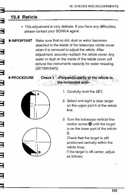
l
~f3~6~-:::
~~
~~'3
~.~~::~3
~,.....,"
.. .
~;3;~~~
~3
~3
~3
~~
~
19. CHECKS AND ADJUSTMENTS
19.4 Reticle
. This adjustment is very delicate. If you have any difficulties,please contact your SOKKIA agent.
~ IMPORTANT Make sure that no dirt, dust or water becomesattached to the inside of the telescope reticle coverwhen it is removed to adjust the reticle. Afteradjustment, securely reattach the reticle cover. Anywater or dust on the inside of the reticle cover willreduce the instruments capacity for water resisting.
(SET5W/5WS)
~ PROCEDURE Check1~1-~l'l:+\.th~hd
1. Carefully level the SET.
2. Select and sight a clear targeton the upper part A of the reticleline.
3. Turn the telescope vertical finemotion screw ~ until the targetis on the lower part of the reticleB.
Check that the target is stillpositioned centrally within thereticle lines.
If the target is off-center, adjustas follows:
123
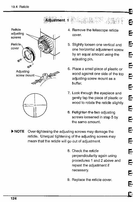
19.4 Reticle
~
~,~JJeJeJ~.1...j&j
eiE--
1~)
E-i
~~~
/),
stment 1 ;¥i
Reticleadjustingscrews
Reticie~cover '"
~
~/ ,)~
Adjusting int~screw mou~T
CD\J
-'\~Z-
4. Remove the telescope reticlecover.
5. Slightly loosen one vertical andone horizontal adjustment screwby an equal amount using theadjusting pin.
6. Place a small piece of plastic orwood against one side of the topadjusting screw mount as abuffer.
7. Look through the eyepiece andgently tap the piece of plastic orwood to rotate the reticle slightly.
8. Retighten the two adjusting
screws loosened in step 5 bythe same amount.
~ NOTE Over-tightening the adjusting screws may damage thereticle. Unequal tightening of the adjusting screws maymean that the reticle will go out of adjustment.
8. Check the reticleperpendicularity again usingprocedures 1 and 2 above andrepeat the adjustment ifnecessary.
9. Replace the reticle cover.
124
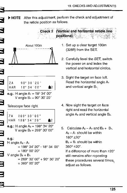
~~ill~;::1~c3
"'~~t~3
19, CHECKS AND ADJUSTMENTS
~I"~~&3
~.'.31="
a8g?=
~~
~ NOTE After this adjustment, perform the check and adjustment ofthe reticle position as follows.
About 100m
.i - - - - - - - - - - - - -- - - -~
ZA 90°30'20"HAR 18°34'00" *2
e.g.: H angle A1 = 18° 34' 00"Vangie B1 = 90° 30' 20"
Telescope face right
ZA 269°30'00"H A R 1 98° 34 ' 20 " *2
e.g.: H angle A2 = 198° 34' 20"Vangie B2 = 269° 30' 00"
e.g.:H angle A2 - A1
= 198° 34' 20" - 18° 34' 00"= 180° 00' 20"
Vangie B2 + B1
= 269° 30' 00" + 90° 30' 20"= 360° 00' 20"
1. Set up a clear target 100m
(328ft) from the SET.
2. Carefully level the SET, switchthe power on and index thevertical and horizontal circles.
3. Sight the target on face left.Read the horizontal angle A1and vertical angle B1;
4. Now sight the target on faceright and read the horizontalangle A2 and vertical angle B2.
5. Calculate A2 - A1 and B2 + B1.
A2 - A1 should be within
180° :t20"B2 + B1 should be within
360° :t20".If a difference of more than :t20"still remains after repeatingthese procedures several times,adjust as follows. .
125
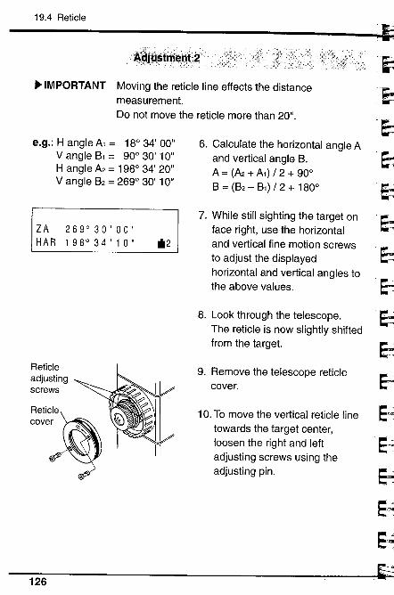
19.4 Reticle
~~Î~~tlt~nt~l; ·
~ IMPORTANT Moving the reticle line effects the distancemeasurement.Do not move the reticle more than 20".
e.g.: H angle A, = 18° 34' 00"
Vangie B, = 90° 30' 10"
H angle A2 = 198° 34' 20"Vangie B2 = 269° 30' 10"
ZA 269°30'00"H A R 1 98° 34 ' 1 0 " *2
Reticleadjustingscrews
Reticie~cover "'~
, )~'~
II
6. Calculate the horizontal angle Aand vertical angle B.A = (A2 + Ai) /2+ 90°B = (B2 - Bi) /2+ 180°
7. While still sighting the target onface right, use the horizontaland vertical fine motion screwsto adjust the displayedhorizontal and vertical angles tothe above values.
8. Look through the telescope.
The reticle is now slightly shiftedfrom the target.
9. Remove the telescope reticlecover.
10. To move the vertical reticle linetowards the target center,loosen the right and leftadjusting screws using theadjusting pin.
nJ
JJ.~J~lei~~J1Ei~~J
,:)126
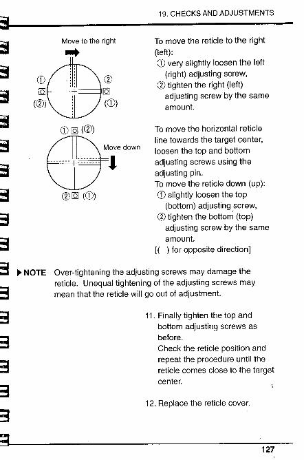
~~~~~"-~~;.,;..'~~-i
~~~~~3
&3
~3
~-3
?=
~
19. CHECKS AND ADJUSTMENTS
Move to the right..CD
IQ
(æ)
æIQ
(CD)
To move the reticle to the right
(left):CD very slightly loosen the left
(right) adjusting screw,æ tighten the right (left)
adjusting screw by the sameamount.
To move the horizontal reticleline towards the target center,loosen the top and bottomadjusting screws using theadjusting pin.To move the reticle down (up):
CD slightly loosen the top
(bottom) adjusting screw,æ tighten the bottom (top)
adjusting screw by the sameamount.
(( ) for opposite direction)
~ NOTE Over-tightening the adjusting screws may damage thereticle. Unequal tightening of the adjusting screws maymean that the reticle will go out of adjustment.
CD IQ (æ)
æ IQ (CD)
11. Finally tighten the top andbottom adjusting screws asbefore.Check the reticle position andrepeat the procedure until thereticle comes close to the targetcenter.
12. Replace the reticle cover.
127
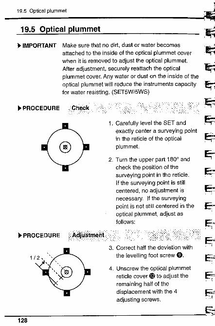
19.5 Optical plummet
19.5 Optical plummet
~ IMPORTANT Make sure that no dirt, dust or water becomesattached to the inside of the optical plummet coverwhen it is removed to adjust the optical plummet.After adjustment, securely reattach the opticalplummet cover. Any water or dust on the inside of theoptical plummet will reduce the instruments capacityfor water resisting. (SET5W/5WS)
~ PROCEDURE \Ch~ck
1. Carefully level the SET andexactly center a surveying pointin the reticle of the opticalplummet.
2. Turn the upper part 1800 andcheck the position of thesurveying point in the reticle.If the surveying point is stillcentered, no adjustment isnecessary. If the surveyingpoint is not still centered in theoptical plummet, adjust asfollows:
~..i¡ ". -
~"1
9:i'999~
i 1
99~- r iE=-__1 1
FJ
~ PROCEDURE
3. Correct half the deviation withthe levelling foot screw 0.
4. Unscrew the optical plummetreticle cover 4f to adjust theremaining half of thedisplacement with the 4adjusting screws.
128
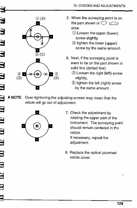
~...u." -.-, I
,. , 19. CHECKS AND ADJUSTMENTS
~~.~3~3
~~¡,..;;
~..~:;;
~~~~-3
~c3
~3
;.'~.3'" .
~¡3
;;~~~
~
Q)(0)
o(0))
5. When the surveying point is onthe part shown in 0 (Q)area:CD Loosen the upper (lower)
screw slightly,
Cl tighten the lower (upper)screw by the same amount.
Q)
(0)
6. Next, if the surveying point isseen to be on the part shown insolid line (dotted line):
æ Loosen the right (left) screwslightly,
G) tighten the left (right) screwby the same amount.
~ NOTE Over-tightening the adjusting screws may mean that thereticle will go out of adjustment.
7. Check the adjustment by
rotating the upper part of theinstrument. The surveying pointshould remain centered in thereticle.If necessary, repeat theadjustment.
8. Replace the optical plummetreticle cover.
~
129.
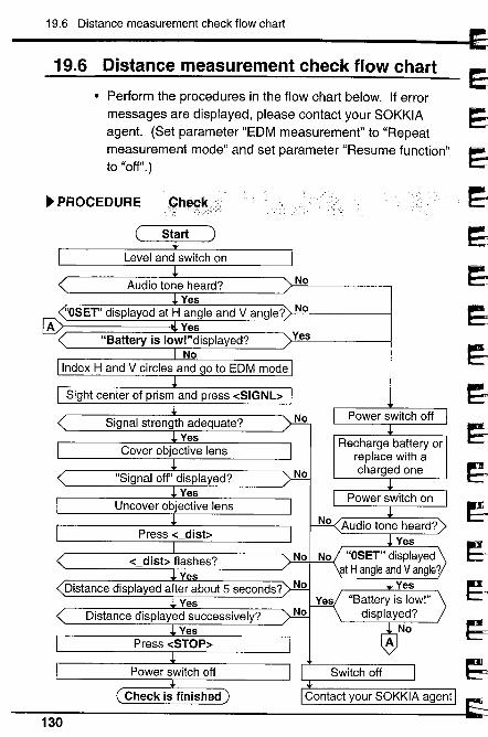
19.6 Distance measurement check flow chart
19.6 Distance measurement check flow chart
· Perform the procedures in the flow chart below. If errormessages are displayed, please contact your SOKKIAagent. (Set parameter "EDM measurement" to "Repeatmeasurement mode" and set parameter "Resume function"to "off".)
~ PROCEDURE Çh~~*
No
A
Audio tone heard?Yes
"OSET" displayed at H angle and Vangie? NoYes
"Battery is low!"displayed?
NoIndex H and V circles and go to EDM mode
Yes
Sight center of prism and press -cSIGNb
Press -c dist;
Signal strength adequate?Yes
Cover objective lens
No
"Signal off' displayed?Yes
Uncover objective lens
No
No-c dist; flashes?
YesDistance displayed after about 5 seconds? No
YesDistance displayed successively?
YesPress -cSTOP::
Power switch off
\, Check is finished
130
J
:i~~.~~~..1~~~~rJrJrJ
~~~
1
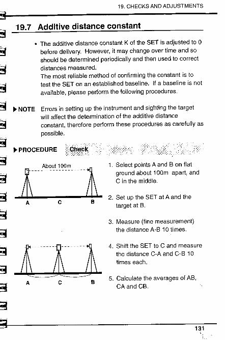
ss~sSt3~
19. CHECKS AND ADJUSTMENTS
¡:~¡i~~~~S~3
~Ë3~:-~~!!~
19.7 Additive distance constant
. The additive distance constant K of the SET is adjusted to 0before delivery. However, it may change over time and soshould be determined periodically and then used to correctdistances measured.The most reliable method of confirming the constant is totest the SET on an established baseline. If a baseline is notavailable, please perform the following procedures.
~ NOTE Errors in setting up the instrument and sighting the targetwil affect the determination of the additive distanceconstant, therefore perform these procedures as carefully aspossible.
~ PROCEDURE
j- _AbO"t '00m_ - - - -/L
A c
1. Select points A and B on flatground about 100m apart, andC in the middle.
B2. Set up the SET at A and the
target at B.
jnn-lnmi-- --A c
3. Measure (fine measurement)the distance A-B 10 times.
4. Shift the SET to C and measurethe distance C-A and C-B 10times each.
B5. Calculate the averages of AB,
CA and CB.
i&_.____._.
131
19.7 Additive distance constant
6. Compute the additive distance Kusing the formula:K = AB - (CA + CB).
7. Obtain the K value several
times.If all K values are greater than:!3mm, please contact yourSOKKIA agent.
~ NOTE Ensure that the target height is the same as the instrumentheight. If the ground is not flat, use an automatic level to setthe correct instrument heights of all points.
132
~'~'.~
~.iJ
1~,dd~eJ~
1~c..
19~J~1~
~1
E:_J
r
~rs1¿'3~,~
~..'....'i_~io=.'.~tr-~
~~~?c3
Ë=~c3
;:.',3"
~3
~
Measurement options selection
20. CHANGING INSTRUMENT PARAMETERS ..... 135
21. CHANGING LOCATION OF FUNCTIONS FOR KEYS.. 14421.1 Key function allocating ................................................ 14621.2 Registered location recalling ...................................... 151~ EXPLANATION Difference between "Enter" and "Key
registration" in key function allocating.... 152
22. POWER SUPPLIES ........................................ 153
23. REFLECTING PRISMS AND ACCESSORIES.. 156
133

134
1
~~~It~EJ
r=~Ej~~rdJ
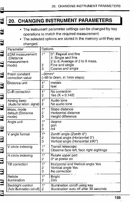
~~ 120.
~.~.~~.,,.
~~~T1-b1
~!I ~...
20. CHANGING INSTRUMENT PARAMETERS
CHANGING INSTRUMENT PARAMETERS I
The instrument parameter settings can be changed by keyoperations to match the required measurement.
. The selected options are stored in the memory until they arechanged.
~~~&~
~~~
;~
~.~
~3
;3~
Parameter Options
EDM measurement 1 * 0*: Repeat and fine(Distance 1: Single and fine
measurement 2 to 9: Average of 2 to 9 meas.mode) 2 Fine and single
3 Coarse and single
Prism constant -30mm*correction value (-99 to Omm, in 1 mm steps)Distance unit 1 * meters
2 feet
C+R correction 1 * No correction2 Yes (K = 0.142)
Aiming beep 1 * Audio tone
(Audio for return signal) 2 No audio tone
Meas. mode 1 * Slope distancedefault (Distance 2 Horizontal distancemode) 3 Height difference
Angle unit 1 * degree2 gon3 mil
Vangie format 1 * Zenith angle (Zenith 0°)
2 Vertical angle (Horizontal 0°)3 Vertical angle (Horizontal :t900)
V circle indexing 1 * Transit telescope2 Observe face left, face right sightings
H circle indexing 1 * Rotate upper part2 0° at power on
Tilt correction 1 * Horizontal and Vertical angle Yes2 Vertical angle Yes3 No correction
Reticle 1 * Brightillumination 2 Dim
Backlight control 1 * Ilumination on/off using key(Auto illumination cut-off) 2 Illumination auto off after 30 secondsi I I
135
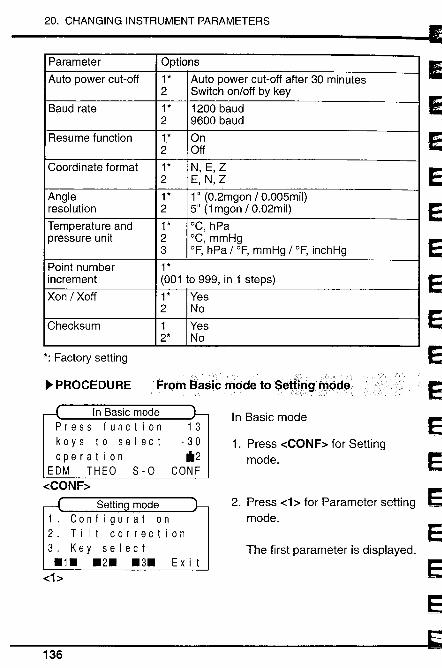
20. CHANGING INSTRUMENT PARAMETERS
Parameter Options
Auto power cut-off 1 * Auto power cut-off after 30 minutes2 Switch on/off by key
Baud rate 1 * 1200 baud2 9600 baud
Resume function 1,* On2 Off
Coordinate format 1 * N, E,Z2 E, N,Z
Angle 1 * 1" (0.2mgon /0.005mil)resolution 2 5" (1 mgon / 0.02mil)
Temperature and 1 * °C, hPapressure unit 2 °C, mmHg
3 OF, hPa / OF, mmHg / OF, inchHg
Point number 1 *
increment (001 to 999, in 1 steps)Xon / Xoff 1 * Yes
2 No
Checksum 1 Yes2* No
The first parameter is displayed.
*: Factory setting
~ PROCEDURE From BasiC mode to Sediflgmc:de
In Basic modePress functionkeys to selectoperation
EDM THEO 8-0-cCONF~
In Basic mode1 3
- 30il2
CONF
1. Press -cCONF~ for Settingmode.
2. Press -c1 ~ for Parameter setting _mode.
Ex i t
136 9
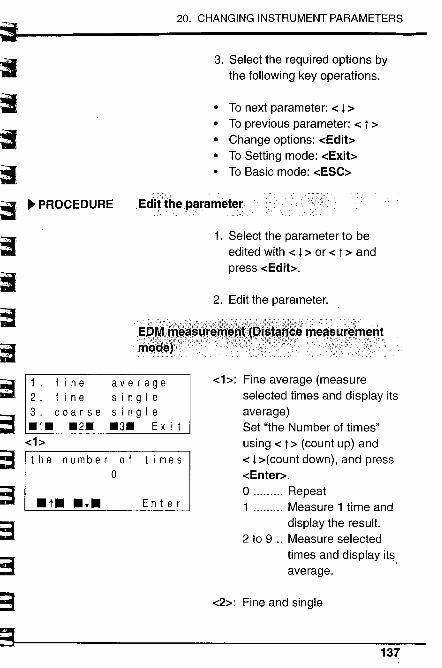
~~irr.20. CHANGING INSTRUMENT PARAMETERS
" I~~~
~J~~~I;;Ii
r=~~~~~'3
~~~~~.
. PROCEDURE
3. Select the required options bythe following key operations.
· To next parameter: -c l ~· To previous parameter: -c t ~· Change options: -cEdit~· To Setting mode: -cExib
. To Basic mode: -cESC~
Editthel:i:rameter. .
1. Select the parameter to beedited with -c l ~ or -c t ~ andpress -cEdib.
2. Edit the parameter.
1. fin e average2. fin e sin g I e
3. coarse sin g I e
.1. .2. .3. Ex i t-c1~
the number ofo
.t. .l.
time s
En t e r
-ch: Fine average (measure
selected times and display itsaverage)Set ''the Number of times"using -c t ~ (count up) and-c l ~(count down), and press-cEnter~.o ........ Repeat1 ......... Measure 1 time and
display the result.2 to 9 .. Measure selected
times and display it$,average.
-c2~: Fine and single
iL.d_ '_M__137
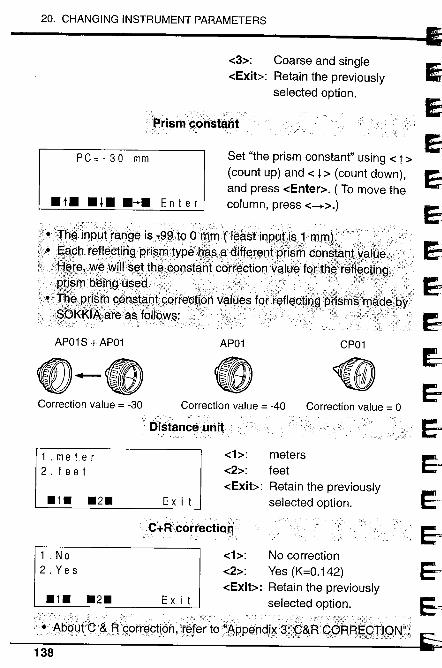
20. CHANGING INSTRUMENT PARAMETERS
-c3~: Coarse and single
-cExib: Retain the previously
selected option.
'PrismçÔñstant
Set ''the prism constant" using -c t ~
(count up) and -c ¡ ~ (count down),and press -cEnter~. ( To move thecolumn, press -c-+~.)
PC=-30 mm
. t. . l. .~. E n t e r
.:.Tn~.:. jn...~lJJ...'...r....a.. ?..9.a.... i.B... -.... ø9.;'ì9 ....0... m.:. ...m.'.r.'.e. ~$t. inP......g~...;iS....i.l.....m........ n;I.1...;..........' .
.. . E' h fl" t' '. t h d'ff t.... t .1....:..U...........................e.................................. .....................;..~9.... rß.~c J~gRn?\r .ype.,~?~ ..'.€lrel1d:.8rl~~.con~,;a .
'.' .~TWíll$~.ttti~.99nBta.ht. corf~ctionya.1 U~ fciPtti~;r.tJgQf; ."?:;tg.9.ÜS~â............ ........... ..f;.... ....... ....... . ..... ...... ... ................. .........
pf,i~tnçØnst~i;t:qorreÇ.tí9n ya.'V~.sf9J ...re(Ißc.tlQ.~.prj$mß;ina:tl~~~yKKI.~arßa.s follQWs: . ..;;.... .
AP01 S + AP01 AP01 CP01
~- (eCorrection value = -30 Correction value = -40 Correction value = 0
"'OistancèÜnit
-c1~: meters
-c2~: feet-cExib: Retain the previously
selected option.
1 . me Ie r2 . fee t
.1. .2. Ex i t
c+Ff.COrrèctioo'.'
-c1~: No correction
-c2~: Yes (K=0.142)
-cExib: Retain the previously
selected option.
1 . No2. Ye s
.1. .2. Ex i t:':.:.-., -, i: ,,--,,'.. - :" ,,~~--_, . " ":':'::",:: - -:-::-::_:-::"':_ - _ .: -::. _ _:.: _ _ _ :,::', r.::_, _ _ :__-;_:Xo": :.,/.-:\\:),__-''. - ',,',,;.(::,y;.,
Ab9Ût;C.~.Bgptr~çtiÓti,'r~ferto:'~ppatidJ.~3i:Ç&RÇQj:R.~gTIQN;'¿
138
~~~~EJ
EJ9~
1
~l.E-~~e=
i(;~~
E=:~
~
~
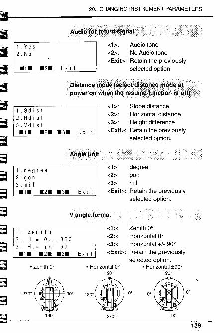
,
t~~~
r'rl~~r=Fr=r=~i
~
""'3i- _
20. CHANGING INSTRUMENT PARAMETERS
~~3~c-3
~-,3
~
~~~Ja;
-c ~:
-c2~:
-cExit:::
Audio toneNo Audio tone
Retain the previouslyselected option.
Di~tanc~'.'power onw
Slope distanceHorizontal distanceHeight differenceRetain the previously
selected option.
degreegonmil
Retain the previously
selected option.
Zenith 0°
Horizontal 0°
Horizontal +/- 90°Retain the previouslyselected option.
. Horizontal :t90°
o.to.-900
139
1 . Yes2. No
.1. .2. Ex i t
-c ~:
-c2~:
-c3~:
-cExit:::
1 . S d i s t2. H d i s t3. V d i s t.1. .2. .3. Ex i t
-c1~:
-c2~:
-c3~:
-cExit:::
1.degree2 . go n
3. mil.1. .2. .3. Ex i t
v.angleformst
-c1~:
-c2~:
-c3~:
-cExit:::
1. Zen i t h2. H.= 0...3603. H.= +/- 90.1. .2. .3. Ex i t
. Horizontal 0°
900
m' lJ 90" 180°.°.
1800
. Zenith 0°
2700
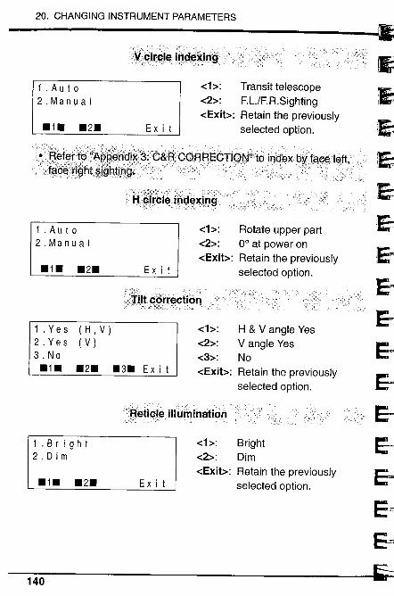
20. CHANGING INSTRUMENT PARAMETERS
~
:i~.~
JeJ~
1
EJEJEJEJ&-
~
eJj
~
.......'.-: "-, ':".'; -.c-'.......,.-'", .. ,",",. '.":.;:¥.9.itØI~ inØ~~Ii1Q
11 . Aut 02.Manual
.1. .2. Ex i t
-c1~:
-c2~:
-cExib:
u_::_::- ..;:':,:.-:
r:,:/¡?
Transit telescopeF.LJF.R.SightingRetain the previously
selected option.
1 . Aut 02.Manual
.1. .2. Ex i t
f: ;:'~"
-(;-Y:,J,è,::,
1 . Yes2. Yes3. No
.1.
(H, V)
(V)
.2. .3. Ex i t
-c1~:
-c2~:
-cExib:
-c1~:
-c2~:
-c3~:
-cExib:
::;~éiiÇ~,~.. ilWfuinafion
1 . B rig h t
2. Dim
.1. .2. Ex i t
-c ~:
-c2~:
-cExib:
Rotate upper part0° at power onRetain the previously
selected option.
H & Vangie Yes
Vangie Yes
NoRetain the previously
selected option.
BrightDim
Retain the previously
selected option.
140
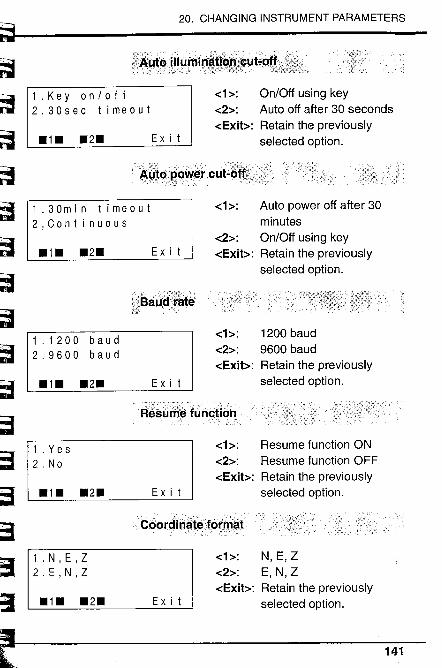
~~~~~~~,'~'ni
20. CHANGING INSTRUMENT PARAMETERS
bø~:Di~~-~~
,~b~-lLi'~.~~
,'i~Lita UIUrni ,
1.Keyon/off2.30sec timeout
.1. .2. Ex i t
-c1~:
-c2~:
-cExit~:
On/Off using keyAuto off after 30 secondsRetain the previouslyselected option.
"'~~JØQ()~~I' ,cut2Õ~~,;:.:);i'
1.30min timeout2,Continuous
.1. .2. Ex i t
f~BaJij'F~tè
1.1200 baud2.9600 baud
.1. .2. Ex i t
-c1~:
-c2~:
-cExit~:
Auto power off after 30minutesOn/Off using keyRetain the previouslyselected option.
-c1~:
-c2~:
-cExit~:
Àésl.Í'ø functiõh
1 . Yes2, No
.1. .2. Ex i t
-c ~:
-c2~:
-cExit~:
. C60ri:inaiéfõl'n'äi:
1 . N, E, Z2. E , N, Z
.1. .2. Ex i t
-c ~:
-c2~:
-cExit~:
1200 baud9600 baudRetain the previouslyselected option.
Resume function ONResume function OFFRetain the previouslyselected option.
N, E,ZE, N,ZRetain the previouslyselected option.
141
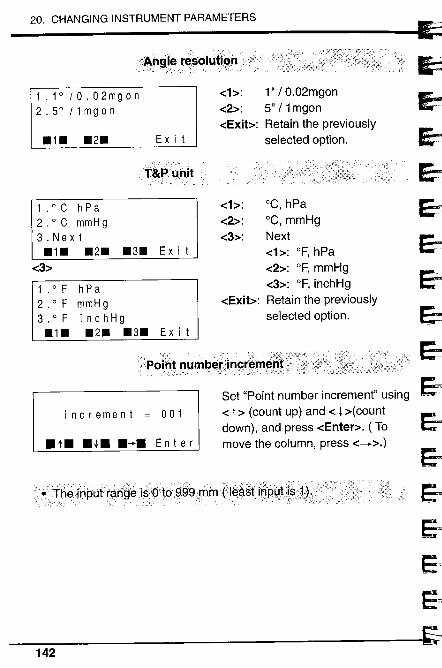
20. CHANGING INSTRUMENT PARAMETERS
""'i'/~~~.-1l
ii
ei~~~eieiei&¡
E)e;~~-,.. iE~
eJ~_J
?~.,. ngl~r~~OÎut..i()..",n,fl'- ..., - ,1.1° /0.02mgon2.5°/1mgon
.1. .2. Ex i t
-c1~:
-c2~:
-cExib:
, ::_~f;,),,~;.:';:;'~ ;., ';";;''-' ,i -:. ~;";,,,-- :'-"'(:,()/
1"&PU,l"it
1.0C hPa2.oC mmHg3. N ext.1. .2.
-c3~
.3. Ex i t
1 . ° F h P a
2 . ° F mmHg
3 . ° F inchHg.1. .2. .3. Ex i t
-c1~:
-c2~:
-c3~:
-cExib:
1" / 0.02mgon5" / 1 mgonRetain the previouslyselected option.
°C, hPa°C, mmHgNext-ch: of, hPa
-c2~: of, mmHg-c3~: of, inchHgRetain the previously
selected option.
increment = 001
. t. . l. .-. E n t e r
Set "Point number increment" using-c t ~ (count up) and -c l ~(countdown), and press -cEnter~. ( Tomove the column, press -c-+~.)
142
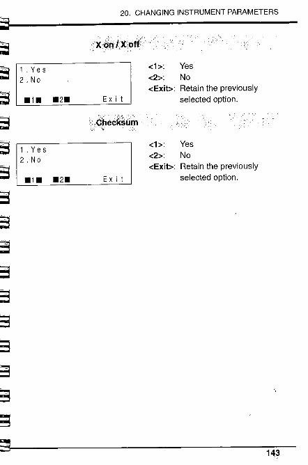
~~t3~t3t3~
20. CHANGING INSTRUMENT PARAMETERS
~3
~~'-"
-,
If'
~8:3:=~~3- ,"'-~
~ ~~=~
~
xi~Qk)()otfi.
1 . Yes2. No
-c1~: Yes
-c2~: No-cExit~: Retain the previously
Ex i t selected option..1. .2.,;".,:;;
iêheêksû..
1 . Yes2.No
.1. .2. Ex i t
-c1:::
-c2~:
-cExit~:
YesNoRetain the previouslyselected option.
ìi
143
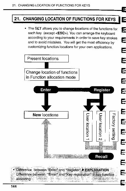
21. CHANGING LOCATION OF FUNCTIONS FOR KEYS
121. CHANGING LOCATION OF FUNCTIONS FOR KEYS , ~,
. The SET allows you to change locations of the functions foreach key (except -cESC;:). You can arrange the keyboardaccording to your requirements in order to save key strokesand to avoid mistakes. You will get the most efficiency bycustomizing function locations for your own applications.
Change location of functionsin Function allocation mode
c c -Ten en IICD CD ('.. .. -00 0 ~(' ('II II en- - CDõ' õ' -=t=i =i =i-i l\ to
Recall
;;,:,',
144
;J~r=~~..J
1
Ei.l~
~~~EJ
i~~~
J

l ~
~
s~I'"~ r- ,~I¡; ~.;~3~3¡i ,
lr3~;;~
~ ""~
21. CHANGING LOCATION OF FUNCTIONS FOR KEYS
. The factory settings are shown below. "User location 2"settings can be changed. If changed, the previous settingswill be erased and cannot be recalled.
Factory setting
EDM mode
8 d i s t0( Fine average ::
o
- 30
~i38d is t A8HV THEO --P 2
PPM M/TRK 81GNL --P3I REM MLM OFF8 --P1
Theodolite mode
0
ZA 112021'200 - 30HAR 350038'100 ~i3
8 d i s t EDM I L LUM --P 2
08 ET HOL D Tilt --P 3
I RE P ZA /% R / L --P 1
Setting-out mode
o
8-0 / COORD8 -30~i3
80 3 D 8 - 0 P 8 - 0 D -+P 2
8 t n P H t. COOR D --P 3
i ME M R E 8 E C A8 H V -- P 1
User location 2
EDM mode
8 d i s t 0
0( Fin e average :: - 30
~i38 d i s t REC COORD --P 2
I A8HV MITRK MEM --P31 REM MLM RE8EC --P1
Theodolite mode
o
ZA 112021'20'0 -30HAR 350038' 100 ~i3B8ang 08ET HOLD --P2
IPPM 81GNL TI It --P3I REP ZA/% R/L --P1
Setting-out mode
o
8 -0 / COORD8 - 303
S,O P 80 HA SO Hd -+P2
18tn P Ht. MITRK --P31 S - 0 D R E 8 E C AS H V -+ P 1
145
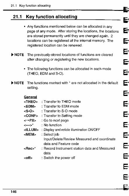
21.1 Key function allocating
~~~"'..
~IE,:i~eieiEJe,eJ~~EJEJ~EJ
l
~
21.1 Key function allocating
· Any functions mentioned below can be allocated in anypage of any mode. After storing the locations, the locationsare stored permanently until they are changed again. 2locations can be registered at the internal memory. Theregistered location can be renewed.
~ NOTE The previously-stored locations of functions are clearedafter changing or registering the new locations.
· The following functions can be allocated in each mode
(THEO, EDM and S-O).
~ NOTE The functions marked with * are not allocated in the defaultsetting.
GeneraldHEO~-cEDM~
-cS-O~-cCONF~-cPX~-c---~ *
-cILLUM~
-cMEM~
-cRec~ *
-coff~
: Transfer to THEO mode: Transfer to EDM mode: Transfer to S-O mode: Transfer to Setting mode: Go to next page: No function: Display and reticle illumination ON/OFF
: Select jobInpuVDelete/Review Measured and coordinatedata and Feature code
: Record Instrument station data and Measureddata
: Switch the power off
146
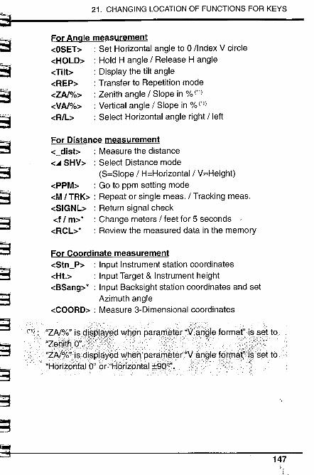
~t:~~,==
~S
21. CHANGING LOCATION OF FUNCTIONS FOR KEYS
~~3
~~S~~~~~~~3
~~.. .
For Angle measurement-cOSET~ : Set Horizontal angle to 0 /Index V circle-cHOLD~ : Hold H angle / Release H angle-cTilt~ : Display the tilt angle-cREP~ : Transfer to Repetition mode-cZAl%~ : Zenith angle / Slope in % ("1)-cVAl%~ : Vertical angle / Slope in % ('1)-cR/b : Select Horizontal angle right / left
For Distance measurement-c_disb : Measure the distance
-c.. SHV~ : Select Distance mode(S=Slope / H=Horizontal / V=Height)
-cPPM~ : Go to ppm setting modeo:M I TRK~ : Repeat or single meas. / Tracking meas.-cSIGNL~ : Return signal check-cf / m~* : Change meters / feet for 5 seconds '-cRCL~* : Review the measured data in the memory
For Coordinate measurement-cStn_P~ : Input Instrument station coordinates-cHt.~ : Input Target & Instrument height
-cBSang~* : Input Backsight station coordinates and setAzimuth angle
o:COORD~ : Measure 3-Dimensional coordinates
"ZAlro,,'iS9J~PJ~X¥d ~hen' parawrter"\Í:~6$IEl.form~Fis.s.~t to
"~r,8¡lrQ".;c,\¡FY"..ii .')';ki/'i" ...... .....i'... .,. "ZA~!o'dirdispl.ayEl9~hrri...pamrr?lElrd'y.angle. lerma,."HórizQhtaIO" or"HprizQntal :b9ao",
'-147
~ ,
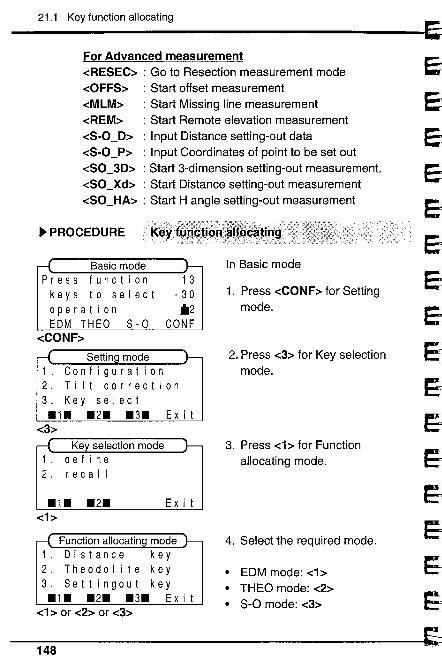
21.1 Key function allocating
~:i=i~
1
eieieie¿e-
1Ei1~1~1..~1~)~j~
~1
ei
For Advanced measurement-cRESEC~ : Go to Resection measurement mode-cOFFS~ : Start offset measurement-cMLM~ : Start Missing line measurement-cREM~ : Start Remote elevation measurement-cS-O_D~ : Input Distance setting-out data-cS-O_P~ : Input Coordinates of point to be set out-cSO_3D~ : Start 3-dimension setting-out measurement.-cSO_Xd~ : Start Distance setting-out measurement-cSO_HA~ : Start H angle setting-out measurement
~ PROCEDURE f(~ý
Basic modePress functionkeys to selectoperationEDM THEO 8-0
-cCONF~
13- 30
62CONF
Ex i t
.1. .2. Exit-c1~
Function allocatin mode1. Distance key2. Theodolite key3, Settingout key.1. .2. .3. Ex it
-c1 ~ or -c2~ or -c3~
In Basic mode
1. Press -cCONF~ for Settingmode.
2. Press -c3~ for Key selectionmode.
3. Press -cb for Function
allocating mode.
4. Select the required mode.
. EDM mode: -c1 ~· THEO mode: -c2~· S-O mode: -c3~
148
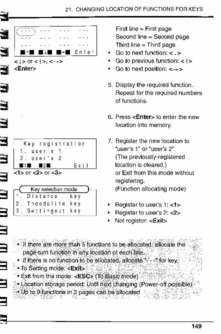
,
~1~t:.,...; ,,I
~~~I- ~~-1
r3~-3
21. CHANGING LOCATION OF FUNCTIONS FOR KEYS
~;-~;=-;
S~~~3
~~ ii~
.-_.......... ..t. .l. .~. En t e r
-c l ~ or -c t ~, '-c--~-cEnter~
Key registration1. use r 's 1
2. user's 2.1. .2. Exit
-c ~ or -c2~ or -c3~
Ke selection modeDistance keyTheodo lit e key
Settingout key
First line = First pageSecond line = Second pageThird line = Third page
· Go to next function: -c l ~· Go to previous function: -c t ~· Go to next position: -c--~
5. Display the required function.
Repeat for the required numbersof functions.
6. Press -cEnter~ to enter the newlocation into memory.
7. Register the new location to"user's 1" or "user's 2".
(The previously-registeredlocation is cleared.)or Exit from this mode withoutregistering.
(Function allocating mode)
· Register to user's 1: -c1 ~· Register to user's 2: -c2~. Not register: -cExit~
ii__ _____.__._.. _ _
149
21.1 Key function allocating
· When Coordinate functions are used, allocate related functions.· For 3-Dimensional coordinates measurement
Allocate -cHt.~ and -cBSang~ with -cCOORD~.-cHt.~ (Input Target and Instrument height)-cBSang~ (Set Azimuth angle) .-cCOORD~ (Measure 3-Dimensional coordinates)If these are not allocated, the previously stored data is used.
150
~E)
~1~1~~r;
~1~~1~19,~i~~~)~11~1
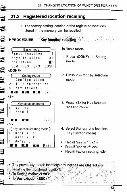
L _'
fi'.' .'....- ~
~l~~....i..:.....;¡..
~ !ç f"1
~~.;.:.'."....'.'.'.¡
. ,.,' ..1,"
r:~.?~~.i..,' "-.-.¡-, .
21. CHANGING LOCATION OF FUNCTIONS FOR KEYS
"
~ -~..;~j .~~~~~~~
;=~-3
~
21.2 Registered location recallng
· The factory settng location or the registered locationsstored in the memory can be recalled.
~ PROCEDUREtK~~'\f¡'~~t¡,~n,r~~~ìli~g'
Basic modePress functionkeys to selectoperationEDM THEa 8-0
-cCONF~
1 3
, 30"2
CONF
In Basic mode
1. Press -cCONF~ for Settingmode.
2. Press -c3~ for Key selectionmode.
3. Press -c2~ for Key functionrecalling mode.
4. Select the required location.
(Key function mode)
· Recall "user's 1 ": -c1 ~· Recall "user's 2": -c2~· Recall Factory setting: -c3~
G""'~"
15;1
Ex i t
.1. .2.-c2~
Ke function recallin1. use r ' s 12, user's 23. default.1. .2. .3.
Ex i t
Ex i t
::J~i!h~......R~aVioq~I~;stor~~!~.cati. ....::......raç~llj.n~...t~..ad~~~i~tat~al.9~ati.
.~Mt~...SøWn~\rn~~~¡;,:?E~ìt~d.. .
.... .Tq;~asiçr.9qß:"fi;Sç;:;
21.2 Registered location recalling
~ EXPLANATION i;~j~èren.9~i~êt~~l~'0'Ënt~~i;dJ~t1 'd~ê?"?~~gistrilti~n;" inkeyfLl.nctiQndàll~cat,irí9
· There are 2 methods for changing the locations of functionsfor keys. By knowing how to use "Enter" or "Keyregistration" properly, it will be easier to operate the SET.
CD -cEnter~ the new location or register the new location:After entering the new location, the functions aredisplayed in the entered location until next changing.
æ Recall the registered locations:After registering a location, the registered location canbe recalled at any time.
For example, if someone enters another location, you canrecall the location you registered.
152
j
:i~1
E1~~
E1
9ei~
1ß~ß
eiEi~
j~~
EJ~j
E'"j
E7~~,
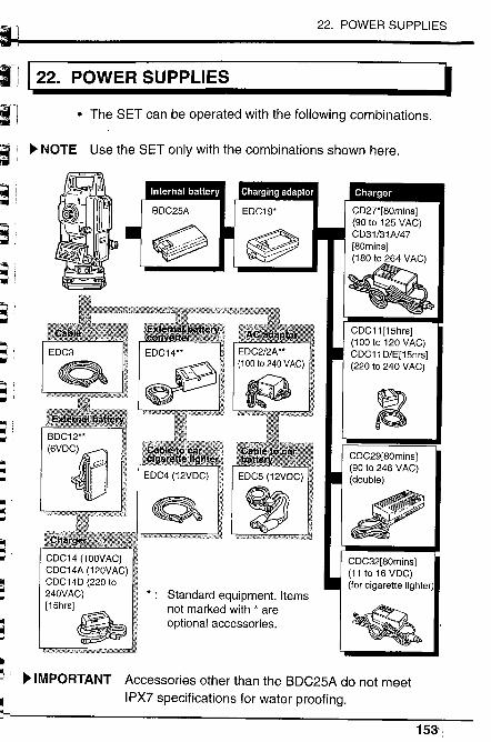
~I
~~il-- i~~F~
Fi~r-ii~:ri- '~"" :"" 'rni :~"".,~ ..
ii.. :..t-..fi--!''-
¡¡fi""If'"
~~..uõ...ii£i11..
l~
22. POWER SUPPLIES
122. POWER SUPPLIES I· The SET can be operated with the following combinations.
~ NOTE Use the SET only with the combinations shown here.
~BDC12"('~(j
CDC14 (100VAC)CDC14A (120VAC)CDC14D (220 to240V AC)
(15hrSJ~ Standard equipment. Items
not marked with * areoptional accessories.
~ (II
~ ~ IMPORTANT Accessories other than the BDC25A do not meet
".l IPX7 specifications for water proofing.~1 15~:~

22. POWER SUPPLIES
~ NOTE When using any external power supply (**), it isrecommended that the BDC25A battery be left in place tobalance the weight on the axes.
. Battery operating left is shortened at extreme temperaturesdue to the battery's Ni-Cd composition.
· If the battery is discharged excessively, its life may beshortened. Store it in a charged state.
. The battery can be recharged about 300 times under
ordinary use (Temperature = 20°C, Humidity = 65%).. The storage temperature is between 0 and 40°C.
. Specifications:
Output voltage: 6VDCCapacity: 1200mAhWater resistance: conforms to IPX7 (BDC25A)Size: 58 x 23 x 92mmWeight: about 0.2kg
ø~n~ryc;har~WCDç21,ÇÍ)Ö3,f,CpÇ:UA orCDC47
· The battery charger becomes warm while charging. This isnormaL.
· How to charge: Connect the charger to the power supply,connect the adaptor to the battery charger and mount thebattery in the adaptor.Then;
· the charging light flashes during charging and lightssteadily when charging is finished. (CDC27/CDC31/CDC47)
· the charging lamp lights on during charging and it flasheswhen the charging is finished. (CDC31 A)
. The charging temperature is between 10 and 40°C.
. Charge the battery until the light remains on.
154
~:19
~~f1E1
~
E~i
e:fj~1
~~"
jr=i
.I
E1
~
\l-
E..riLlr
6
~ ~ PRECAUTION
L~
,~¡J
~~~t£r.Ii~
l~ii~'"
~ff'"
~~r-~
~..
22. POWER SUPPLIES
· Specifications:Input: CDC27: 90 to 125V AC, 50/60Hz, 20VA
CDC31/31A147: 180 to 264V AC, 50/60Hz, 20VAOutput: 7.5V DC, 1.2ACharging time at 25°C: about 80 minutes (BDC25A)Size: 66 x 124 x 45mmWeight: CDC27: about 0.35kg
CDC31/31A147: about 0.38kg
Forthe.'.use()l'øxt~rnã!p()wer...~qpplies
. Ensure that the car cigarette lighter has 12V DC output andthat the negative terminal is grounded. Leave the enginerunning during use.
. Before using EDC2, set the voltage selector to the correctvoltage.
. EDC14 has a breaker switch. If you short circuit the batteryor the polarity is not correct, the breaker will switch off thepower. When the breaker switches off the power, removethe rubber cover and set the breaker switch so that a redmark appears.
155 ,
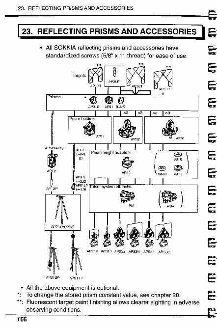
23. REFLECTING PRISMS AND ACCESSORIES
123. REFLECTING PRISMS AND ACCESSORIES l
· All SOKKIA reflecting prisms and accessories havestandardized screws (5/8" x 11 thread) for ease of use.
~i~AP~i2
AP12P
~AP71 (=SPS3)
~APS 12P
**~~tfAP3 ~
*~ ~ GAP01S (CAP)
**
Targets ~ ij~ d AP30PAP IT
'i~ lP31AP61(=P4)
2m
ê- ( ~)S818
~o ~AP41
APS 1 2 APS 1 J APS32 APS34 APS31 APS33
APSI1P
· All the above equipment is optionaL.*. To change the stored prism constant value, see chapter 20.**. Fluorescent target paint finishing allows clearer sighting in adverse
observing conditions.
156
E:
Eê
~.l
ei
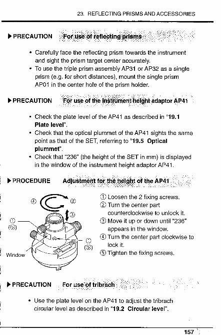
'-..rL.. ~ PRECAUTION
rLIdF"i¡L-Jri!
, '~~'-In~iLqiv
~~r-f-"'f'"
23. REFLECTING PRISMS AND ACCESSORIES
· Carefully face the reflecting prism towards the instrumentand sight the prism target center accurately.
. To use the triple prism assembly AP31 or AP32 as a singleprism (e.g. for short distances), mount the single prismAP01 in the center hole of the prism holder.
~ PRECAUTIONF~tô~edfmø1; entdi1~Îglitadaptor AF'41
. Check the plate level of the AP41 as described in "19.1Plate level".
· Check that the optical plummet of the AP41 sights the samepoint as that of the SET, referring to "19.5 Opticalplummet".
· Check that "236" (the height of the SET in mm) is displayedin the window of the instrument height adaptor AP41 .
,Lq ~ PROCEDURE~f"ii A(jj IJst~~nlfqith~Jil~igbl()f theAP41i
";'to_o,___ :.'.,/_ ..',:'. '__::~:):;"~'::::"""c~'_'~:_' _.'-, u', ,__ -_ -_.___., .
l_Ic~ ~ir''' øç..æ~(æ)~~.~ ~~ G)~-::~ A~C ((S)~..i Window ~i: ~'"
~p
Q) Loosen the 2 fixing screws.æ Turn the center part
counterclockwise to unlock it.
G) Move it up or down until "236"appears in the window.
G) Turn the center part clockwise to
lock it.~ Tighten the fixing screws.
§j ~ PRECAUTION!;....
~~--
~E- ,
. Use the plate level on the AP41 to adjust the tribrachcircular level as described in "19.2 Circular level".
157 ';
158
:¡
~~~
1~)~~
~~
1~__,.1
.10.~r-"'J.
l~..l"iLir Appendix 1: Manually indexing the vertical circle by~ . face left, face right measurements.. 161
r-~t~Ir~
~~~~r"~hL~~~
Appendices
Appendix 2: For distance measurement of thehighest accuracy........................ 162
Appendix 3: Earth-curvature and refractioncorrection ........................................... 164
Appendix 4: Standard accessories ................... 165
Appendix 5: Optional accessories ................;.... 166
STANDARD EQUIPMENT ............................... 168
MAl NTENAN C E ......... ............................... ................. 169
SPECIFICATIONS ..................................................... 170
ATMOSPHERIC CORRECTION CHART .............. 174ì~
~-.,~
~-~ REGU LATIONS ......................................................... 175"
"
l ~8~..¡
159.

160
=~j~:iia
j
eij~1
S1j
EJ
EJEA
ii~!~
1
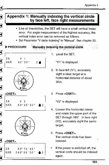
J-~l"'~.' :
lri
~
r~J..~r:~~
r~~'~Iir;;.:~
~~.'
r,;,a..'~~:~í
t~r~l
i~~~~Io~~:~t:i
aIo~~..~
~.~t!
~
~.~i:~¡.
~~~f:!.
Appendix 1
Appendix 1: Manually indexing the vertical circleby face left, face right measurements
· Like all theodolites, the SET will have a small vertical indexerror. For angle measurement of the highest accuracy, thevertical index error can be removed as follows:
. Set Parameter "V circle indexing" to "Manual". See chapter 20.
~ PROCEDURE M.......... a..riu....ány..inde..... ~in~ t"øc.¥. erjiC'al.....~i.têlê':. ~--';' ,.,," ":J :",:" - --'. - ".- ,~y' -'. ;', ,".',- ", '-/
ZA
HAR
V 1
60 ' 00" 2 iI
-cOSET~
ZA
HAR
V 260°00'00" il2
-cOSET~
~.~
"::;~:~
ZA
HAR89°10'40"
240° 00 ' 00 " iI 2
1. Level the SET.
"V1" is displayed.
2. In face left (V1), accurately
sight a clear target at ahorizontal distance of about30m.
3. Press -cOSET~.
"V2" is displayed.
4. Loosen the horizontal clamp
and rotate the upper part of theSET through 180°. In face right
(V2), accurately sight the sametarget.
5. Press -cOSET~.
The vertical circle has beenindexed.
. If the power is switched off, thevertical circle should be indexedagain.
161,.
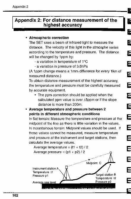
Appendix 2
Appendix 2: For distance measurement of thehighest accuracy
· Atmospheric correctionThe SET uses a beam of infrared light to measure thedistance. The velocity of this light in the atmosphe variesaccording to the temperature and pressure. The distancewill be changed by 1 ppm by:
- a variation in temperatu re of 1°C- a variation in pressure of 3.6hPa
(A 1 ppm change means a 1 mm difference for every 1 km ofmeasured distance.)To obtain distance measurement of the highest accuracy,the temperature and pressure must be carefully measuredby accurate equipment.
· The ppm correction should be applied when thecalculated ppm value is over :t5ppm or if the slopedistance is more than 200m.
· Average temperature and pressure between 2
points in different atmospheric conditionsIn flat terrain: Measure the temperature and pressure at themidpoint of the line as there is little variation in the values.In mountainous terrain: Midpoint values should be used. Ifthose values cannot be measured, measure temperatureand pressure at the instrument and target stations, thencalculate the average values.
Average temperature = (t1 + t2) / 2Average pressure = (p1 + p2) /2
~~.~
Instrument station ATemperature t1Pressure p1
162
~~~~~
)
~uu'
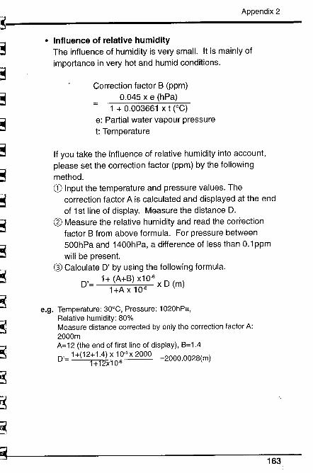
~r;~~J~~it;;r:.:~;;r~:i,
~;;:I'f;~i
~.~'I
~Jr;:~I~~
¡~..~r,;~H
~.~",::'i
LI~~:=l
~
~.~~,.~~,~L;;~;=s
Lìc:;r=i
~,~~ -
;~~~~
Appendix 2
· Influence of relative humidityThe influence of humidity is very smalL. It is mainly ofimportance in very hot and humid conditions.
Correction factor B (ppm)0.045 x e (hPa)
1 + 0.003661 x t (0C)e: Partial water vapour pressuret: Temperature
If you take the influence of relative humidity into account,please set the correction factor (ppm) by the followingmethod.CD Input the temperature and pressure values. The
correction factor A is calculated and displayed at the endof 1st line of display. Measure the distance D.
(g Measure the relative humidity and read the correctionfactor B from above formula. For pressure between500hPa and 1400hPa, a difference of less than 0.1 ppmwill be present.
Q) Calculate D' by using the following formula.
D'= 1 + (A+B) X10,6 x D (m)1 +A x 10'6
e.g. Temperature: 30°C, Pressure: 1020hPa,
Relative humidity: 80%Measure distance corrected by only the correction factor A:2000mA=12 (the end of first line of display), B=1.4
D'= 1 +(12+ 1.4) x 10-6 X 2000 =2000.0028(m)1+12x10'6
16~
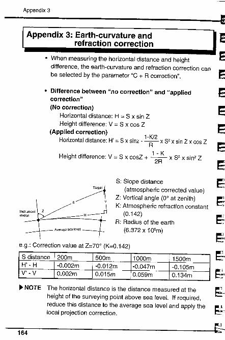
Appendix 3
Appendix 3: Earth-curvature andrefraction correction
· When measuring the horizontal distance and heightdifference, the earth-curvature and refraction correction canbe selected by the parameter "C + R correction".
· Difference between "no correction" and "appliedcorrection"(No correction)
Horizontal distance: H = S x sin ZHeight difference: V = S x cos Z
(Applied correction) 1-K/2Horizontal distance: H' = 8 x sinz - -A x 82 x sin Z x cos Z
Height difference: V = S x cosZ + 1 ;RK x S2 x sin2 Z
~S H~S: Slope distance
(atmospheric corrected value)Z: Vertical angle (0° at zenith)K: Atmospheric refraction constant
(0.142)R: Radius of the earth
(6.372 x 10⁶m)
Instrument Zslalion
Average sea level
e.g.: Correction value at Z=70° (K=0.142)
S distance 200m 500m 1000m 1500mH' - H -O.002m -0.012m -0.047m -0.105mV' - V 0.002m 0.015m O.059m 0.134m
~ NOTE The horizontal distance is the distance measured at theheight of the surveying point above sea leveL. If required,reduce this distance to the average sea level and apply thelocal projection correction.
164
~
~~
j~~E1
~~I;~
11 .I
~t.~~...:i"'JI
~~.
~1
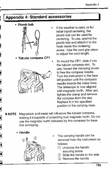
~s~i
~~S
Appendix 4
II Appendix 4: Standard accessories· Plumb bob
. Tubular compass CP7
. If the weather is calm, or for
initial tripod centering, theplumb bob can be used forcentering. To use, unwind theplumb bob and attach it to thehook inside the centeringscrew. Use the cord grip pieceto adjust the cord length.
. To mount the CP7, slide it intothe tubular compass slot. Touse, loosen the clamping screwto free the compass needle.Turn the instrument in the faceleft position until the compassneedle bisects the index lines.The telescope is now alignedwith magnetic north. After use,tighten the clamp and removethe compass from the slot.Replace it in the specifiedposition in the carrying case.
~=il~~J~.i ~
!r:o
., NOTE Magnetism and metal will influence the tubular compass,making it incapable of projecting true magnetic north. Do notuse the magnetic north indicated by this compass for baseline surveying.
The carrying handle can beremoved from the instrument asfollows:CD Unscrew the handle
securing screw(l Slide the handle to the side
G) Remove the handle
,li
~~r
~i"~T
~:~p;~:i
,.lG:J~t:~
~;=i~,=id
~:,~t~i~
,~~i
· Handle
165
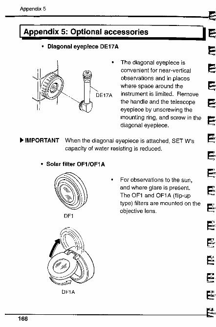
Appendix 5
I Appendix 5: Optional accessories· Diagonal eyepiece DE17 A
· The diagonal eyepiece isconvenient for near-verticalobservations and in placeswhere space around theinstrument is limited. Removethe handle and the telescopeeyepiece by unscrewing themounting ring, and screw in thediagonal eyepiece.
~ IMPORTANT When the diagonal eyepiece is attached, SET W'scapacity of water resisting is reduced.
· Solar fiter OF1/0F1 A
DF1
DF1A
For observations to the sun,and where glare is present.The OF1 and OF1A (flip-uptype) filters are mounted on theobjective lens.
I;
~ei~~~
ß
~~e¡
~t=J
eJ~_jl
E;
~~
166

~~~,j
~'I
¡L
~~11
~i
~ì
~;1
~1
~i
~G-
~~~~j
S~
Appendix 5
· Electronic field book SDR series
l
SDR
f! Modem
r-
Q~aPrinter ~Computer
IPlotter
The SDR series collects andstores slope distance and,vertical and horizontal angledata from the SET.
Calculations can be performedon the data so that themeasurements can be verifiedin the field. The stored datacan be transmitted to a dataprocessing system.
~ IMPORTANT When the SET W is connected with the SDR series,its capacity of water resisting is reduced.
167\,

STANDARD EOUIPMENT
I STANDARD EQUIPMENT
t: :Ic&
0)æ~~- (!~'Q= CD
CI~G)
(S
CD SET5F/5FS/5W/5WS ..............1o Internal battery, BDC25A ........ 1Q) Battery charging adaptor,
EDC19 .............'...................... 1G) Battery charger,
CDC27/31/31A/47..............,.... 1
CI Tubular compass, CP7 ............ 1(§ Lens cap ................................. 1(f Lens hood .............................. 1CI Vinyl cover .............................. 1
~~i
~ ~QJ & ~~~Oiê Ø"a) i
i:i9
J~iilUll!
J
~J:;~~-:i~::1
~î""Jl~i
~~
~
CI Plumb bob .............................. 1(j Tool pouch .............................. 1(j Screwdriver .................'..,....... 1(j Lens brush ..,.......................... 1QJ Adjusting pin ........................... 1(3 Cleaning cloth ........................ 1¡ß Operator's manual.................. 1
Atmospheric correction chart .. 1~ Carring case (SC129) ............. 1
I
168
~rri i MAINTENANCE~ 1. Make sure that the inside of the carrying case and the
~ instrument are dry before closing the case. If moisture is_ trapped inside the case, it may cause the instrument to
trust.~~~
(!;~r
~r~~~
r~1-~..~l~~
MAINTENANCE
I
2. Always clean the instrument before returning it to the case.The lens requires special care. Dust it off with the lensbrush first, to remove minute particles. Then, afterproviding a little condensation by breathing on the lens,wipe it with a soft clean cloth or lens tissue.
3. Do not wipe the displays and keyboard or carrying case
with an organic solvent.
4. Store the SET in a dry room where the temperature
remains fairly constant.
5. Check the tripod for loose fit and loose screws.
6. If any trouble is found on the rotatable portion, screws (0,CD, ~, qy, 4D, ~ and ~) or optical parts (e.g. lens), contactyour SOKKIA agent.
7. When the instrument is not used for a long time, check it atleast once every 3 months.
8. When removing the SET from the carrying case, never pullit out by force. The empty carrying case should then beclosed to protect it from moisture.
9. Check the SET for proper adjustment periodically tomaintain the instrument accuracy.
169
SPECIFICATIONS
I SPECIFICATIONSI
..
TelescopeLength: 165mmAperture: 45mmMagnification: 30xImage: ErectResolving power: 3"
:iField of view: 1 °30' (26m / 1000m)Minimum focus: 1.3mReticle illumination: Bright or dim settngs
(Selectable with parameter)
Angle measurementHorizontal and vertical Incremental with 0 index
circles type:
1Angle units: Degree / gon / mil (Selectable with
parameter) ;Display range:
Horizontal angle: -3599° 59' 59" to 3599° 59' 59"Vertical angle: 0°0'0" to 359° 59' 59" EMinimum display: 1" (0.2mgon / 0.005mil) /5" (1 mgon /
~0.02mil)(Selectable with parameter)
Accuracy: Standard deviation of mean ofmeasurementtake in positions I and II (DIN 18723)
15" (1.5mgon /0.02mil) EMeasuring time: Less than 0.5sec. dAutomatic compensator: Selectable ON (V & H / only V) / OFFType: Liquid, 2-axis tilt sensor
~lMinimum display: Same as the angle display ..".Range of compensation: :t3' Io,.1)Measuring mode:Horizontal angle: Right / Left / Repetition / Hold -.\1~
(Selectable with keyboard) ."u )
Vertical angle: Zenith 0 / Horizontal O/Horizontal :t90°'""i
(Selectable with parameter)
-1Slope in % (Selectable with keyboard)
170 ~9
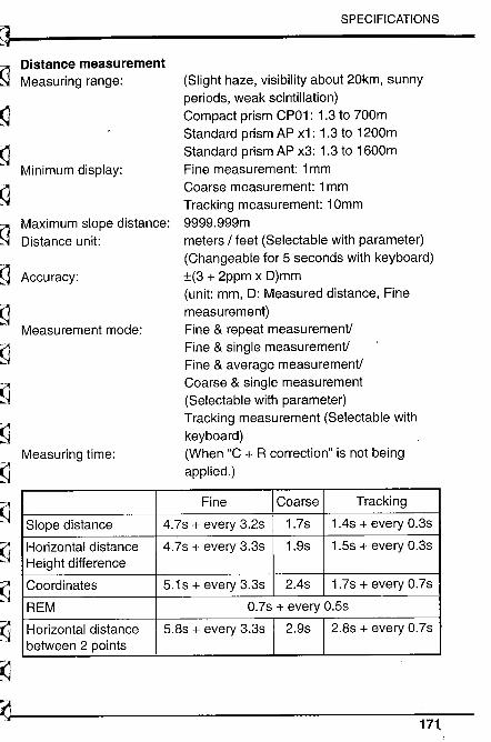
~j~
~a
~1
~d1lr~~-i
~~~I,
~-~~"~~-
~I;~~.~'I
~~~~
~~u~n.-ii
~~:~~l;:rr~"
~.~¡¡; ,
r-~~..
~-:¡
~~~~,Jâ.
SPECIFICATIONS
Distance measurementMeasuring range: (Slight haze, visibility about 20km, sunny
periods, weak scintillation)Compact prism CP01: 1.3 to 700mStandard prism AP x1: 1.3 to 1200mStandard prism AP x3: 1.3 to 1600mFine measurement: 1 mmCoarse measurement: 1 mmTracking measurement: 10mm9999.999mmeters / feet (Selectable with parameter)
(Changeable for 5 seconds with keyboard):t(3 + 2ppm x D)mm
(unit: mm, D: Measured distance, Finemeasurement)Fine & repeat measurement!Fine & single measurement!Fine & average measurement!Coarse & single measurement
(Selectable with parameter)Tracking measurement (Selectable withkeyboard)
(When "C + R correction" is not beingapplied.)
Minimum display:
Maximum slope distance:Distance unit:
Accuracy:
Measurement mode:
Measuring time:
Fine Coarse Tracking
Slope distance 4.7s + every 3.2s 1.7s 1.4s + every 0.3s
Horizontal distance 4.7s + every 3.3s 1.9s 1.5s + every 0.3sHeight difference
Coordinates 5.1 s + every 3.3s 2.4s 1.7s + every O.7s
REM 0.7s + every 0.5s
Horizontal distance 5.8s + every 3.3s 2.9s 2.8s + every 0.7sbetween 2 points
17t
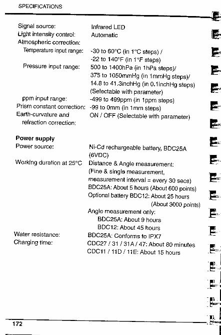
SPECIFICATIONS
Signal source:Light intensity control:
Atmospheric correction:Temperature input range:
Pressure input range:
ppm input range:Prism constant correction:Earth-curvature and
refraction correction:
Power supplyPower source:
Working duration at 25°C
Water resistance:Charging time:
Infrared LEDAutomatic
-30 to 60°C (in 1°C steps) /-22 to 140°F (in 1°F steps)500 to 1400hPa (in 1 hPa steps)/375 to 1050mmHg (in 1 mmHg steps)/14.8 to 41.3inchHg (in 0.1 inchHg steps)
(Selectable with parameter)-499 to 499ppm (in 1 ppm steps)-99 to Omm (in 1 mm steps)ON / OFF (Selectable with parameter)
Ni-Cd rechargeable battery, BDC25A
(6VDC)Distance & Angle measurement:
(Fine & single measurement,measurement interval = every 30 secs)BDC25A: About 5 hours (About 600 points)
Optional battery BDC12: About 25 hours
(About 3000 points)Angle measurement only:
BDC25A: About 9 hoursBDC12: About 45 hours
BDC25A: Conforms to IPX7CDC27/ 31/ 31A/ 47: About 80 minutesCDC11 /110 / 11 E: About 15 hours
ri~~~
1~..i;l
1~
~"1~1
111l ~,~-rni~,
~jI,t'li ~.~-I~
-~h- -'
:'j1-l -a~,~ '~
,llh"~~..~
, I t~.J, , I..: l!"ilcE-.
JJ172
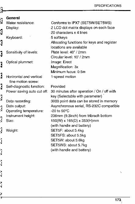
,
~~~Lr~~t~~~~L~¡L
~S3
~~,
SPECIFICATIONS
GeneralWater resistance:Display:
Keyboard:
Sensitivity of levels:
Optical plummet:
Horizontal and verticalfine motion screw:
Self-diagnostic function:Power saving auto cut off:
Data recording:Data output:Operating temperature:Instrument height:Size:
Weight:
Conforms to IPX7 (SET5W/SET5WS)2 LCD dot matrix displays on each face20 characters x 4 lines5 soft keysAllocating functions for keys and registerlocations are availablePlate level: 40" /2mmCircular level: 10' /2mmImage: ErectMagnification: 3xMinimum fucus: 0.5m1-speed motion
Provided30 minutes after operation / On / off withkey (Selectable with parameter) ,3000 point data can be stored in memoryAsynchronous serial, RS-232C compatible-20 to 50°C236mm (9.3inch) from tribrach bottom150(W) x 165(D) x 353(H)mm
(with handle and battery)SET5F: about 5.4kgSET5FS: about 5.5kgSET5W: about 5.6kgSET5WS: about 5.7kg
(with handle and battery)
~~~~~
173
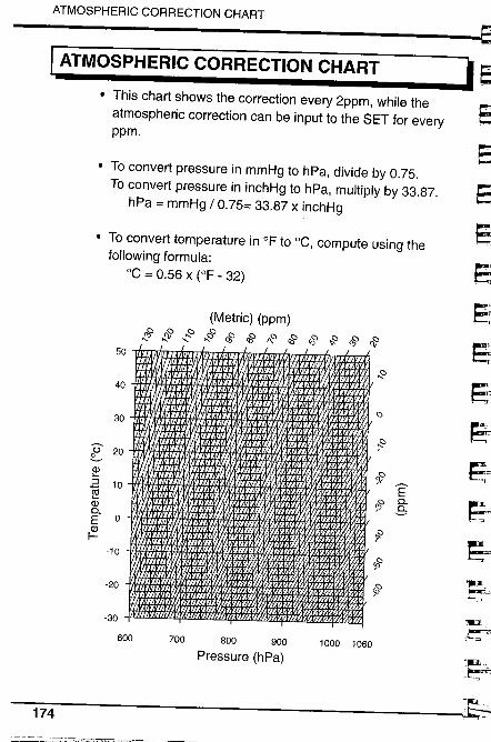
ATMOSPHERIC CORRECTION CHART
I ATMOSPHERIC CORRECTION CHART· This chart shows the correction every 2ppm, while the
atmospheric correction can be input to the SET for everyppm.
· To convert pressure in mmHg to hPa, divide by 0.75.To convert pressure in inchHg to hPa, multiply by 33.87.
hPa = mmHg / 0.75= 33.87 x inchHg
· To convert temperature in of to °C, compute using thefollowing formula:
°C = 0.56 x (OF - 32)
50
(Metric) (ppm)
~ ~ ..:: ~ rf c§ 1\0 c§ & ,s c§ ct
30
f
::40
°
Ü 20~::
ci=i 101iaiD-E 0ciI-
~ ÊOJ,o D-B
,10
#-20 ~
-30
600 700 800 900Pressure (hPa)
1000 1060
174
J.
~
~. __'1
-1U..~___I
~i:~l¡~~riri~~rri~I.~...,~t:i~.d
REGULATIONS
I REGULATIONS
Radio Frequency InterferenceJ
WARNING: Changes or modifications to this unit notexpressly approved by the party responsible for compliancecould void the user's authority to operate the equipment.
NOTE: This equipment has been tested and found to complywith the limits for a Class A digital device pursuant to Part 15of the FCC Rules. These limits are designed to providereasonable protection against harmful interference when theequipment is operated in a commercial environment. Thisequipment generates, uses, and can radiate radio frequencyenergy and, if not installed and used in accordance with theinstruction manual, may cause harmful interferencE) to radiocommunications. Operation of this equipment in a residentialarea is likely to cause harmful interference in which case theuser wil be required to correct the interference at his ownexpense.
Notice for CanadaThis Class A digital apparatus meets all requirements ofCanadian Interference-Causing Equipment Regulations.Cet appareil numérique de la Class A respecte to utes lesexigences du Réglement sur Ie matériel brouilleur du Canada.
175
-i .. ai
CE
Dec
lara
iion
of C
onfo
rmty
in 3
ccrd
aiic
e w
ith E
MC
Dir
ectiv
e 89
/3.:6
ÆE
C o
f ih
e E
urop
ean
Com
mun
iiyC
E C
onfo
nnity
Dec
lart
ion
in a
ccor
danc
e w
iih E
Me
Dir
eciv
e 89
/JJ6
lC o
r th
e E
urop
ea C
omm
unty
We
he=
i'ilh
dec
lare
Lba
l ibe
und
cmie
nlio
ried
inst
rrnc
ni, i
n vi
ew o
f its
dc.
~i81
l and
iype
ofco
nstu
ciio
n, f
ully
com
plie
s lI
'iùi t
be r
elev
ant b
nsic
rad
io in
lerf
i:ciic
e rc
quile
mei
mof
1be
EM
C D
irec
ivc.
Shou
ld tb
e in
stru
men
t be
mod
ifie
d w
ithou
t agr
ecm
eDt,
Ibis
dec
lilra
iíoii
beC
1lD
~ in
valid
.
We
here
with
deo
lare
miii
the
unde
rmcn
lione
d in
stru
men
t, in
vie
w o
r ii~
de.
ign
and
type
Ort
onsi
ruct
ion,
ful
ly c
ompl
ies
with
the
rele
vt b
asc
raio
inie
ñeri
nce
requ
ircm
enis
of ih
e E
Me
Dir
eÎvc
.Sh
ould
the
inst
rum
ent b
e m
odif
ied
with
out a
gree
enl,
'his
dec
lart
ion
beco
mes
inv;
lid.
bmru
men
i De.
crip
tioo:
Tot
al S
taiio
n (S
urey
ing
Insi
rmen
l)In
S1ru
men
l Des
crip
tion:
TO
lal S
tatio
n (S
urve
ying
Ins
trum
ent)
Model Name : SEl5W
Model Name SETSF, SETSFS
Rel
evan
t EC
Dir
ectiv
e: E
MC
Dir
eive
(89
/336
/EE
C)
Ver
sion
: 91f
263/
EE
C, 9
21IÆ
EC
, 93/
68Æ
EC
Rel
evan
t EC
Dir
ectiv
e: E
MC
Dir
eciv
e (8
9IJJ
6lE
C)
Ver
ion:
911
263Æ
EC
, 921
1/E
C, 9
J/68
ÆC
App
lied
Hnr
roni
cd S
land
.rd:
EM
l EN
SO
O81
-1 1
mE
NSS
022
U94
- C
lasB
EN
S008
2-2
1~5
I!S01
40 i9
9E
NS0
141i
99E
N6i
oo4-
2lm
EN
6iO
OO
-4-2
19
9'
App
lied
Har
oni:i
ed S
tand
ard'
EM
I EN
SO
OH
I_j ,
=E
MS
EN
SO
OH
2-21
995
Dat
il ...
......
......
.?.,f
./2.J
.....
Fir
.... .
.....
SQ
KiJ
!,'yI
_..
SOK
KIA
B, V
,lr
åi!M
&lr
eOeV
Ra
DaR
'liis
~lN
l.133
2EA
AJm
ere
Dat
e ..
......
....m
l...~
..S..~
.~...
Firm
:.. ..
..s9.
K-A
..~,y
.,....
......
Add
ress
: ....
...~~
-~.~
!:.~
~.~.
~..e
_~...
Y.~
...p~
!.~!
.~G
-...i
.:._~
.:.~~
~~_.
.~~.
.~~~
...
SOK
KIA
B. V
,1n
i8lll
nDe
V88
Oai
n!lil
slN
L-1
332E
AA
lmer
8A
ddre
ss. .
...-
r.i:.
~.'!,
~0~~
~~.i.
i:...P
.~..y
_~:n
~..P
.~~~
1~~~
~~i..
.~.'.
..~.~
~.l.t
..M_.
~~~r
~..,.
R""
""",
,,,, S
ig",
"" .
~ ~
Nam
e of
Rcp
rcol
Miv
e: S
teph
en B
laik
ie~
epre
cnla
live'
5 po
iiion
; Eur
opea
n vi
ce P
resi
dent
Rep
reci
laci
ve.~
Sigi
alur
e:
~ 'l~
" .
sieP
hC1~
Eur
opea
vic
e Pr
esid
ent
Nam
e of
Rep
rese
nlai
ive
Rep
resn
tativ
e's
posi
tion:
, rr~
rJ~
rJ~
rr
IT r
n m
m m
m~
_/l~
_l__
i:..=
;j..~
i:.i=
- i.:
..
o m o o :i - o "" 3 ;: i. C C! o Dr
"" D) - õ' :i
:i m G) c ~ a z CJ
~~~t ~
"
r ~ "
l J
~~ ~.5 ~
5 ...~, :§
\ìu j ë
gi3 ~ò
1~
it .,"
~ - .~
il u11 Õ"' .~
u.~
~ 8~Æl .is.~
r-~ Ë õ.
2.~
g' .~,¡ '"2 !J ë;¡ Ë 11 ë
f3s
& Æ0. !in'ö ~ a ii-t
riririI~I~I£~
~~~~
Ì
REGULATIONS
~Ê""
l
177
MEMO