Embed Size (px)
Citation preview
3GPP2 X.S0050-0 Version: 1.0 Date: January 2008
Session Initiation Protocol (SIP) to ISDN User Part (ISUP) Interworking
COPYRIGHT 3GPP2 and its Organizational Partners claim copyright in this document and individual Organizational Partners may copyright and issue documents or standards publications in individual Organizational Partner's name based on this document. Requests for reproduction of this document should be directed to the 3GPP2 Secretariat at [email protected]. Requests to reproduce individual Organizational Partner's documents should be directed to that Organizational Partner. See www.3gpp2.org for more information.

Revision History Revision Date
1.0 Initial Publication January 2008
X.S0050-0 v1.0
i
Session Initiation Protocol (SIP) to ISDN User Part (ISUP) Interworking 1
Contents 2
List of Figures.............................................................................................................................................................................vi 3
List of Tables ............................................................................................................................................................................viii 4
Foreword......................................................................................................................................................................................x 5
1 Scope..................................................................................................................................................................................1 6
2 References ..........................................................................................................................................................................1 7
3 Definitions and Abbreviations............................................................................................................................................4 8
3.1 Definitions ................................................................................................................................................................4 9
3.2 Abbreviations............................................................................................................................................................4 10
4 General ...............................................................................................................................................................................5 11
4.1 General Interworking Overview ...............................................................................................................................5 12
5 Network Characteristics .....................................................................................................................................................6 13
5.1 Key Characteristics of ISUP-based CS Networks ....................................................................................................6 14
5.2 Key Characteristics of IM CN Subsystem ................................................................................................................6 15
6 Interworking with CS Networks.........................................................................................................................................6 16
6.1 Interworking Reference Model.................................................................................................................................6 17
6.1.1 Interworking Reference Points and Interfaces ..............................................................................................6 18
6.1.2 Interworking Functional Entities ..................................................................................................................7 19
6.1.2.1 Void...............................................................................................................................................7 20
6.1.2.2 Media Gateway Control Function (MGCF) .................................................................................. 7 21
6.1.2.3 IP Multimedia - Media Gateway Function (IM-MGW) ................................................................ 7 22
6.2 Control Plane Interworking Model ...........................................................................................................................7 23
6.3 User Plane Interworking Model................................................................................................................................7 24
7 Control Plane Interworking ................................................................................................................................................7 25
7.1 General .....................................................................................................................................................................8 26
7.2 Interworking between CS Networks Supporting ISUP and the IM CN Subsystem.................................................. 8 27
7.2.1 Services Performed by Network Entities in the Control Plane .....................................................................8 28
7.2.1.1 Services Performed by the SS7 Signalling Function.....................................................................8 29
7.2.1.2 Void...............................................................................................................................................9 30
7.2.1.3 Services of the MGCF...................................................................................................................9 31
7.2.1.4 Services of the SIP Signalling Function ........................................................................................9 32
7.2.2 Signalling Between Network Entities in the Control Plane ..........................................................................9 33
7.2.2.1 Signalling Between the SS7 Signalling Function and the MGCF ................................................. 9 34
7.2.2.2 Signalling Between the MGCF and SIP Signalling Function........................................................9 35
7.2.3 SIP-ISUP protocol interworking...................................................................................................................9 36
7.2.3.1 Incoming Call Interworking from SIP to ISUP at I-MGCF ..........................................................9 37
7.2.3.1.1 Sending of IAM ........................................................................................................9 38
X.S0050-0 v1.0
ii
7.2.3.1.2 Coding of the IAM..................................................................................................10 1
7.2.3.1.2.1 Called Party Number ........................................................................ 10 2
7.2.3.1.2.2 Nature of Connection Indicators.......................................................11 3
7.2.3.1.2.3 Forward Call Indicators ....................................................................11 4
7.2.3.1.2.4 Calling Party's Category ...................................................................12 5
7.2.3.1.2.5 User Service Information..................................................................12 6
7.2.3.1.2.6 Calling Party Number.......................................................................14 7
7.2.3.1.2.7 Generic Address ...............................................................................16 8
7.2.3.1.2.8 Void ..................................................................................................17 9
7.2.3.1.2.9 Original Called Number ...................................................................17 10
7.2.3.1.2.10 Redirecting Number .........................................................................18 11
7.2.3.1.2.11 Redirection Information ...................................................................18 12
7.2.3.1.2.11a Jurisdiction Information ...................................................................19 13
7.2.3.1.2.12 Hop Counter (National Option) ........................................................19 14
7.2.3.1.2.12a Transit Network Selection ................................................................19 15
7.2.3.1.3 Sending of COT ......................................................................................................20 16
7.2.3.1.4 Receipt of ACM......................................................................................................20 17
7.2.3.1.5 Receipt of CPG ....................................................................................................... 21 18
7.2.3.1.5a Receipt of ANM......................................................................................................21 19
7.2.3.1.6 Sending of the Release message (REL) ..................................................................21 20
7.2.3.1.7 Coding of the REL ..................................................................................................22 21
7.2.3.1.8 Receipt of the Release Message ..............................................................................23 22
7.2.3.1.9 Receipt of RSC, GRS or CGB (H/W Oriented) ...................................................... 25 23
7.2.3.1.10 Autonomous Release at I-MGCF............................................................................25 24
7.2.3.1.11 Internal Through Connection of the Bearer Path .................................................... 25 25
7.2.3.2 Outgoing Call Interworking from ISUP to SIP at O-MGCF .......................................................25 26
7.2.3.2.1 Sending of INVITE.................................................................................................25 27
7.2.3.2.2 Coding of the INVITE ............................................................................................26 28
7.2.3.2.2.1 REQUEST URI Header....................................................................26 29
7.2.3.2.2.2 SDP Media Description ....................................................................27 30
7.2.3.2.2.3 P-Asserted-Identity – From and Privacy Header Fields ...................30 31
7.2.3.2.2.4 History-Info Header.......................................................................... 33 32
7.2.3.2.2.5 Max Forwards Header ......................................................................35 33
7.2.3.2.3 Receipt of CONTINUITY.......................................................................................35 34
7.2.3.2.4 Sending of ACM and Awaiting Answer Indication ................................................36 35
7.2.3.2.5 Coding of the ACM.................................................................................................37 36
7.2.3.2.5.1 Backward call indicators ..................................................................37 37
7.2.3.2.6 Sending of the Call Progress Message (CPG)......................................................... 38 38
7.2.3.2.7 Coding of the CPG..................................................................................................38 39
7.2.3.2.7.1 Event Information.............................................................................38 40
7.2.3.2.7a Receipt of 200 OK (INVITE) .................................................................................38 41
7.2.3.2.8 Sending of the Answer Message (ANM) ................................................................38 42
7.2.3.2.9 Coding of the ANM ................................................................................................39 43
7.2.3.2.9.1 Backwards Call Indicators................................................................39 44
7.2.3.2.10 Void ........................................................................................................................39 45
7.2.3.2.11 Void ........................................................................................................................39 46
7.2.3.2.12 Receipt of Status Codes 4xx, 5xx or 6xx ................................................................ 39 47
7.2.3.2.12.1 Void ..................................................................................................41 48
7.2.3 2.13 Receipt of a BYE ....................................................................................................41 49
7.2.3.2.14 Receipt of the Release Message ..............................................................................41 50
7.2.3.2.15 Receipt of RSC, GRS or CGB (H/W Oriented) ...................................................... 41 51
7.2.3.2.16 Autonomous Release at O-MGCF .......................................................................... 41 52
7.2.3.2.17 Special Handling of 580 Precondition Failure Received in Response to 53
Either an INVITE or UPDATE...............................................................................42 54
7.2.3.2.17.1 580 Precondition Failure Response to an INVITE ........................... 42 55
X.S0050-0 v1.0
iii
7.2.3.2.17.2 580 Precondition Failure Response to an UPDATE within an 1
Early Dialog......................................................................................42 2
7.2.3.2.18 Sending of CANCEL ..............................................................................................42 3
7.2.3.2.19 Receipt of SIP Redirect (3xx) Response ................................................................. 43 4
7.2.3.3 Timers..........................................................................................................................................43 5
7.3 Void ........................................................................................................................................................................43 6
7.4 Supplementary Services..........................................................................................................................................43 7
7.4.1 Calling Line Identification Presentation/Restriction (CLIP/CLIR) ............................................................43 8
7.4.2 COLP/COLR ..............................................................................................................................................44 9
7.4.3 Void ............................................................................................................................................................44 10
7.4.4 Void ............................................................................................................................................................44 11
7.4.5 Void ............................................................................................................................................................44 12
7.4.6 Call Forwarding Busy (CFB)/ Call Forwarding No Reply (CFNR) / Call Forwarding Unconditional 13
(CFU)..........................................................................................................................................................44 14
7.4.7 Call Deflection (CD)...................................................................................................................................44 15
7.4.8 Explicit Call Transfer (ECT) ......................................................................................................................44 16
7.4.9 Call Waiting................................................................................................................................................44 17
7.4.10 Call Hold.....................................................................................................................................................44 18
7.4.10.1 Session Hold Initiated from the IM CN Subsystem Side ............................................................44 19
7.4.10.2 Session Hold Initiated from the CS Network Side ......................................................................45 20
7.4.11 Void ............................................................................................................................................................46 21
7.4.12 Void ............................................................................................................................................................46 22
7.4.13 Void ............................................................................................................................................................46 23
7.4.14 Conference Calling (CONF) / Three-Party Service (3PTY).......................................................................46 24
7.4.15 Void ............................................................................................................................................................47 25
7.4.16 Void ............................................................................................................................................................47 26
7.4.17 Multi-Level Precedence and Pre-emption (MLPP).....................................................................................47 27
7.4.18 Void ............................................................................................................................................................47 28
7.4.19 Void ............................................................................................................................................................47 29
7.4.20 Void ............................................................................................................................................................47 30
7.4.21 User-to-User Signalling (UUS)...................................................................................................................47 31
7.4.22 Void ............................................................................................................................................................47 32
7.4.23 Void ............................................................................................................................................................47 33
7.5 Void ........................................................................................................................................................................47 34
8 User Plane Interworking...................................................................................................................................................47 35
8.1 Void ........................................................................................................................................................................47 36
8.2 Interworking between IM CN Subsystem and TDM-based CS Network ...............................................................47 37
8.3 Transcoding Requirements .....................................................................................................................................48 38
9 MGCF – IM-MGW Interaction........................................................................................................................................48 39
9.1 Overview ................................................................................................................................................................48 40
9.2 Mn Signalling Interactions .....................................................................................................................................48 41
9.2.1 Network Model...........................................................................................................................................49 42
9.2.2 Basic IM CN Subsystem Originated Session..............................................................................................49 43
9.2.2.1 Void.............................................................................................................................................49 44
9.2.2.2 Void.............................................................................................................................................49 45
9.2.2.3 ISUP ............................................................................................................................................49 46
9.2.2.3.1 IM-MGW Selection ................................................................................................49 47
X.S0050-0 v1.0
iv
9.2.2.3.2 IM CN Subsystem Side Termination Reservation ..................................................49 1
9.2.2.3.3 IM CN Subsystem Side Session Establishment ......................................................50 2
9.2.2.3.4 CS Network Side Circuit Reservation.....................................................................50 3
9.2.2.3.5 Through-Connection ...............................................................................................50 4
9.2.2.3.6 Continuity Check ....................................................................................................50 5
9.2.2.3.7 Codec Handling.......................................................................................................50 6
9.2.2.3.8 Voice Processing Function...................................................................................... 50 7
9.2.2.3.9 Failure Handling in MGCF ..................................................................................... 51 8
9.2.2.3.10 Message Sequence Chart.........................................................................................51 9
9.2.3 Basic CS Network Originated Session........................................................................................................53 10
9.2.3.1 Void.............................................................................................................................................53 11
9.2.3.2 Void.............................................................................................................................................53 12
9.2.3.3 ISUP ............................................................................................................................................53 13
9.2.3.3.1 IM-MGW Selection ................................................................................................53 14
9.2.3.3.2 CS Network Side Circuit Reservation.....................................................................53 15
9.2.3.3.3 IM CN Subsystem Side Termination Reservation ..................................................53 16
9.2.3.3.4 IM CN Subsystem Side Session Establishment ......................................................53 17
9.2.3.3.5 Called Party Alerting ..............................................................................................53 18
9.2.3.3.6 Called Party Answer ............................................................................................... 54 19
9.2.3.3.7 Through-Connection ...............................................................................................54 20
9.2.3.3.8 Continuity Check ....................................................................................................54 21
9.2.3.3.9 Codec Handling.......................................................................................................54 22
9.2.3.3.10 Voice Processing Function...................................................................................... 54 23
9.2.3.3.11 Failure Handling in MGCF ..................................................................................... 54 24
9.2.3.3.12 Message Sequence Chart.........................................................................................54 25
9.2.3.4 Handling of Forking ....................................................................................................................56 26
9.2.3.4.1 Detection of Forking ...............................................................................................56 27
9.2.3.4.2 IM CN Subsystem Side Session Establishment ......................................................56 28
9.2.3.4.3 IM CN Subsystem Side Session Establishment Completion...................................57 29
9.2.3.4.4 Message Sequence Chart.........................................................................................57 30
9.2.4 Session Release Initiated from IM CN Subsystem Side .............................................................................60 31
9.2.4.1 Void.............................................................................................................................................60 32
9.2.4.2 ISUP ............................................................................................................................................60 33
9.2.4.2.1 Session Release in the IM CN Subsystem Side ......................................................60 34
9.2.4.2.2 Session Release in the CS Network Side ................................................................60 35
9.2.4.2.3 Message Sequence Chart.........................................................................................60 36
9.2.5 Session Release Initiated from CS Network Side .......................................................................................61 37
9.2.5.1 Void.............................................................................................................................................61 38
9.2.5.2 ISUP ............................................................................................................................................61 39
9.2.5.2.1 Session Release in the CS Network Side ................................................................61 40
9.2.5.2.2 Session Release in the IM CN Subsystem Side ......................................................61 41
9.2.5.2.3 Message Sequence Chart.........................................................................................61 42
9.2.6 Session Release Initiated by MGCF ...........................................................................................................62 43
9.2.6.1 Void.............................................................................................................................................62 44
9.2.6.2 ISUP ............................................................................................................................................62 45
9.2.6.2.1 Session Release in the CS Network Side ................................................................62 46
9.2.6.2.2 Session Release in the IM CN Subsystem Side ......................................................62 47
9.2.6.2.3 Message Sequence Chart.........................................................................................62 48
9.2.7 Session Release Initiated by IM-MGW ......................................................................................................62 49
9.2.7.1 Void.............................................................................................................................................62 50
9.2.7.2 ISUP ............................................................................................................................................62 51
9.2.7.2.1 Session Release in the CS Network Side ................................................................62 52
X.S0050-0 v1.0
v
9.2.7.2.2 Session Release in the IM CN Subsystem Side ......................................................63 1
9.2.7.2.3 Message Sequence Chart.........................................................................................63 2
9.2.8 Handling of RTP Telephone Events ...........................................................................................................64 3
9.2.8.1 Void.............................................................................................................................................64 4
9.2.8.2 Sending and Receiving DTMF Digits Inband to/from CS CN (ISUP)........................................64 5
9.2.9 Session Hold Initiated from IM CN Subsystem..........................................................................................65 6
9.2.9.1 Hold Request ...............................................................................................................................65 7
9.2.9.2 Resume Request ..........................................................................................................................65 8
9.2.9.3 Message Sequence Chart.............................................................................................................65 9
9.2.10 Session Hold Initiated from CS Network ...................................................................................................66 10
9.2.10.1 Message Sequence Chart.............................................................................................................67 11
X.S0050-0 v1.0
vi
List of Figures 1
Figure 1 IM CN subsystem to CS network logical interworking reference model........................................................6 2
Figure 2 Control plane Interworking between CS Networks Supporting ISUP and the IM CN Subsystem .................8 3
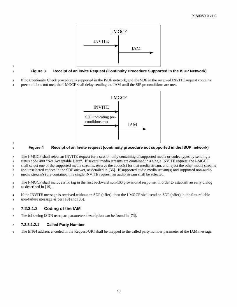
Figure 3 Receipt of an Invite Request (Continuity Procedure Supported in the ISUP Network) ................................10 4
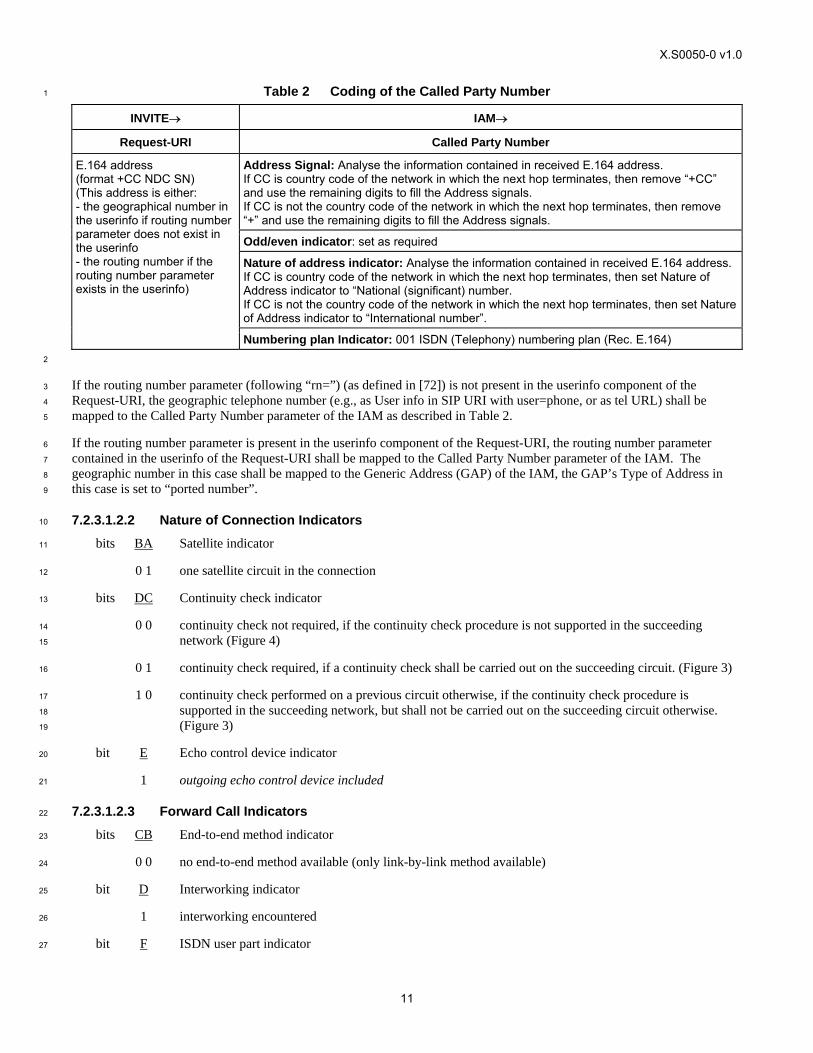
Figure 4 Receipt of an Invite request (continuity procedure not supported in the ISUP network).............................. 10 5
Figure 5 Sending of COT ............................................................................................................................................20 6
Figure 6 The Receipt of ACM (“Subscriber Free”).....................................................................................................20 7
Figure 7 The Receipt of ACM (BCI other than “Subscriber Free”) ............................................................................21 8
Figure 8 Receipt of CPG (Alerting).............................................................................................................................21 9
Figure 9 Receipt of ANM............................................................................................................................................21 10
Figure 10 Receipt of the Bye method ............................................................................................................................22 11
Figure 11 Receipt of Cancel method .............................................................................................................................22 12
Figure 12 Receipt of an IAM (En Bloc Signalling in CS network)...............................................................................26 13
Figure 13 Receipt of COT (Success) .............................................................................................................................36 14
Figure 14 Sending of ACM (Receipt of first 180 ringing) ............................................................................................36 15
Figure 15 Sending of ACM (Ti/w2 elapses) ..................................................................................................................36 16
Figure 16 Sending of ACM (Receipt of 183 Session Progress) ....................................................................................37 17
Figure 17 Sending of CPG (Alerting)............................................................................................................................38 18
Figure 18 Sending of ANM...........................................................................................................................................38 19
Figure 19 Receipt of Status Codes 4xx, 5xx or 6xx ......................................................................................................39 20
Figure 20 Receipt of BYE Method................................................................................................................................41 21
Figure 21 Receipt of COT (Failure). .............................................................................................................................42 22
Figure 22 Receipt of SIP Response Code 3xx...............................................................................................................43 23
Figure 23 Session hold/resume initiated from the IM CN subsystem side ....................................................................45 24
Figure 24 Session Hold/Resume Initiated from the CS Network Side ..........................................................................46 25
Figure 25 IM CN Subsystem to TDM-based CS network User Plane Protocol Stack .................................................. 48 26
Figure 26 Network model..............................................................................................................................................49 27
Figure 27 Basic IM CN Subsystem Originating Session, ISUP (Message Sequence Chart).........................................52 28
Figure 28/1 Basic CS Network Originating Session – ISUP (Message Sequence Chart) ................................................ 55 29
Figure 28/2 Basic CS Network Originating Session – ISUP (Message Sequence Chart) ................................................ 56 30
Figure 29/1 CS Network Originating Session with Forking – ISUP (Message Sequence Chart).....................................58 31
Figure 29/2 CS Network Originating Session with Forking, ISUP (Message Sequence Chart continued) ...................... 59 32
Figure 30 Session Release from IM CN Subsystem Side for ISUP (Message Sequence Chart) ...................................60 33
Figure 31 Session Release from CS Network Side for ISUP (Message Sequence Chart).............................................61 34
Figure 32 Session Release Initiated by MGCF for ISUP (Message Sequence Chart) ...................................................62 35
Figure 33 Session Release Initiated by the IM-MGW for ISUP (Message Sequence Chart) ........................................ 63 36

X.S0050-0 v1.0
vii
Figure 34 Activation of Processing of DTMF Digits Received in RTP for Sending the Digits inband to CS CN 1
(Message Sequence Chart) ............................................................................................................................64 2
Figure 35 Session Hold from IM CN Subsystem ..........................................................................................................66 3
Figure 36 Session Hold from CS Network ....................................................................................................................67 4
X.S0050-0 v1.0
viii
List of Tables 1
Table 1 Interworking Capabilities between ISUP and SIP profile for 3GPP2 .............................................................8 2
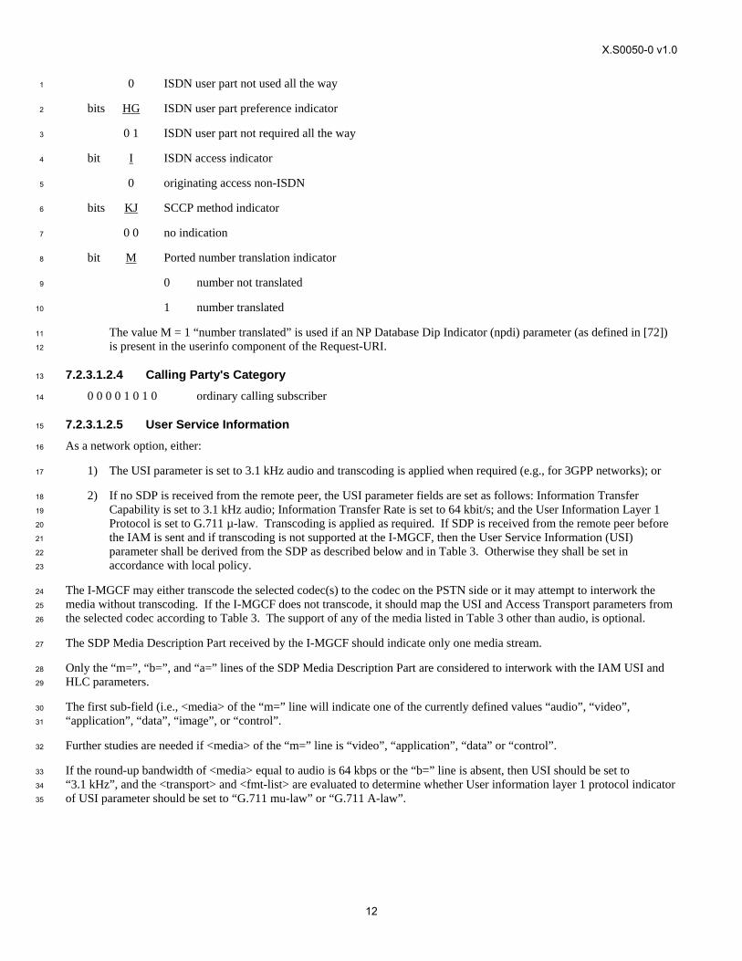
Table 2 Coding of the Called Party Number ..............................................................................................................11 3
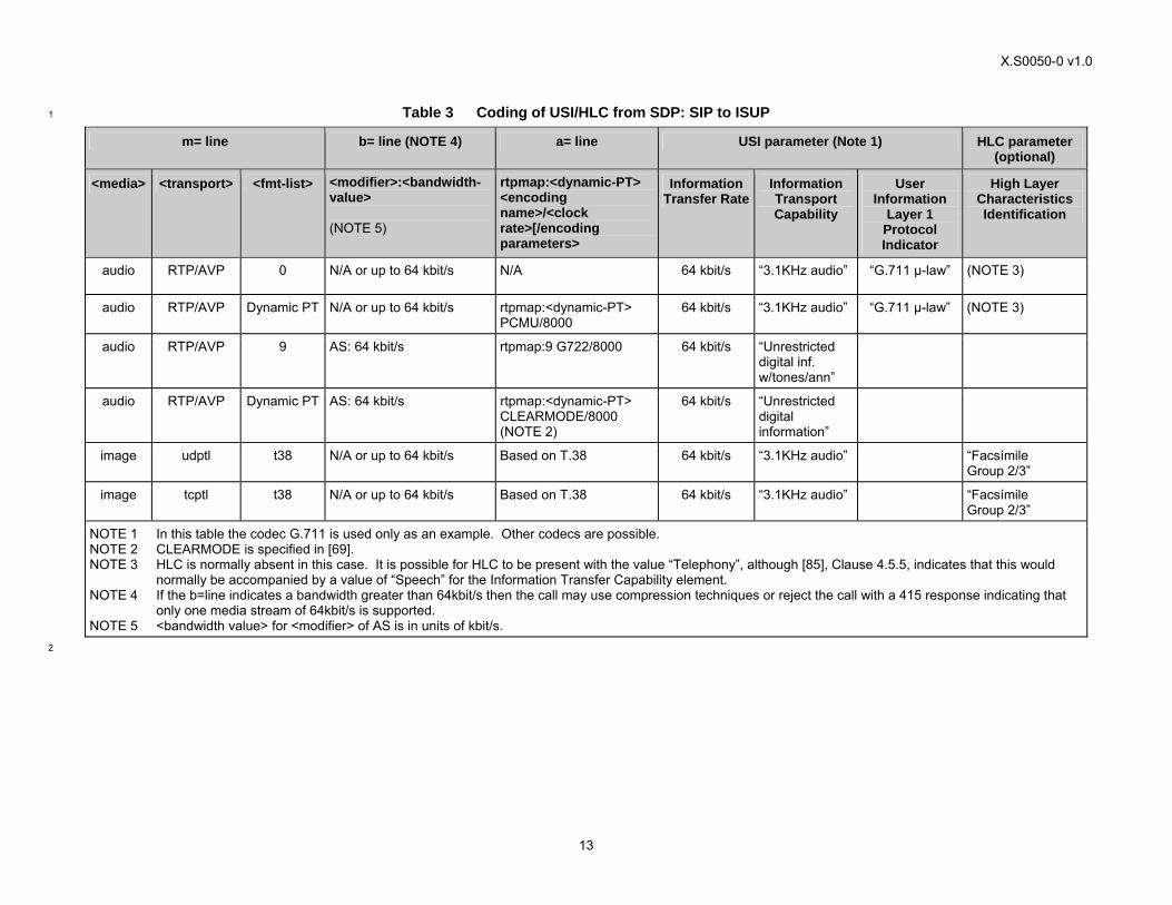
Table 3 Coding of USI/HLC from SDP: SIP to ISUP................................................................................................13 4
Table 4 Mapping of SIP From/P-Asserted-Identity/Privacy headers to CLI parameters ...........................................14 5
Table 5 Setting of Network-Provided ISUP Calling Party Number Parameter with a CLI (Network Option) .......... 15 6
Table 6 Mapping of P-Asserted-Identity and Privacy Headers to ISUP Calling Party Number Parameter ............... 15 7
Table 7 Mapping of SIP from Header Field to ISUP Generic Address (Supplemental User Provided Calling 8
Address – Not Screened) Parameter (Network Option) ................................................................................16 9
Table 8 Mapping of SIP Request-URI to ISUP generic address (ported number) parameter ....................................16 10
Table 9 Mapping of SIP History-Info Header Fields to Original Called Number (OCN)..........................................17 11
Table 10 Mapping of SIP History-Info Header Fields to Redirecting Number............................................................18 12
Table 11 Mapping of SIP History-Info Header Fields to Redirection Information......................................................18 13
Table 12 Mapping of Reason Parameter of the SIP History-Info Header to (Original) Redirecting Reason...............18 14
Table 13 Mapping of JIP in P-Asserted-Identity Header into ISUP JIP Parameter .....................................................19 15
Table 14 Max Forwards -- Hop Counter ......................................................................................................................19 16
Table 15 ACM Interworking........................................................................................................................................20 17
Table 16 CPG Interworking .........................................................................................................................................21 18
Table 17 Coding of the REL ........................................................................................................................................22 19
Table 18 Mapping of SIP Reason Header Fields into Cause Indicators Parameter......................................................22 20
Table 19 Receipt of the Release Message (REL).........................................................................................................23 21
Table 20 Mapping of Cause Indicators Parameter into SIP Reason Header Fields......................................................24 22
Table 21 Autonomous Release at I MGCF ..................................................................................................................25 23
Table 22 Mapping Called Party Number and FCI Ported Number Translation Indicator (when GAP for the 24
Ported Number is not Included) to SIP Request-URI....................................................................................26 25
Table 23 Mapping of Generic Address (ported) and Called Party Number (When Both are Included), and FCI 26
Ported Number to SIP Request-URI .............................................................................................................27 27
Table 24 Mapping of Transit Network Selection to SIP Request-URI ........................................................................27 28
Table 25 Coding of SDP Media Description Lines from USI: ISUP to SIP ................................................................ 29 29
Table 26 Interworked Contents of the INVITE Message.............................................................................................30 30
Table 27 Mapping ISUP CLI Parameters to SIP Header Fields...................................................................................30 31
Table 28 Mapping of Generic Address (Supplemental User Provided Calling Address – Not Screened) to SIP 32
From Header Fields.......................................................................................................................................32 33
Table 29 Mapping of Calling Party Number Parameter to SIP P-Asserted-Identity Header Fields.............................32 34
Table 30 Mapping of ISUP Calling Party Number Parameter to SIP From Header Fields..........................................33 35
Table 31 Mapping of ISUP APRIs into SIP Privacy Header Fields.............................................................................33 36
Table 32 Mapping of ISUP JIP into SIP P-Asserted-Identity Header Fields ...............................................................33 37
Table 33 Mapping of Original Called Number (OCN) to SIP History-Info Header Fields..........................................34 38
X.S0050-0 v1.0
ix
Table 34 Mapping of Redirecting Number to SIP History-Info Header Fields............................................................34 1
Table 35 Mapping of Redirection Information to SIP History - Info Header Fields....................................................35 2
Table 36 Mapping of (Original) Redirecting Reason to Reason parameter of the SIP History-Info header ................35 3
Table 37 Hop counter-Max Forwards ..........................................................................................................................35 4
Table 38 4xx/5xx/6xx Received on SIP Side of O-MGCF ..........................................................................................39 5
Table 39 Autonomous Release at O-MGCF ................................................................................................................42 6
Table 40 Timers for Interworking................................................................................................................................43 7
Table 41 Mapping between ISUP and SIP for the Conference Calling (CONF) and Three-Party Service 8
(3PTY) Supplementary Service ....................................................................................................................46 9
X.S0050-0 v1.0
x
Foreword 1
(This foreword is not part of this document). 2
This document was prepared by 3GPP2 TSG-X. 3
This document contains portions of material copied from 3GPP document number TS 29.163[1]. The copyright on the 3GPP 4
document is owned by the Organizational Partners of 3GPP (ARIB - Association of Radio Industries and Businesses, Japan; 5
CCSA – China Communications Standards Association, China; ETSI – European Telecommunications Standards Institute; 6
ATIS – Alliance for Telecommunication Industry Solutions, USA ; TTA - Telecommunications Technology Association, 7
Korea; and TTC – Telecommunication Technology Committee, Japan), which have granted license for reproduction and for 8
use by 3GPP2 and its Organizational Partners. 9
X.S0050-0 v1.0
1
1 Scope 1
This document specifies the principles of interworking between the 3GPP2 IP Multimedia (IM) CN subsystem and ISUP 2
based legacy CS networks, in order to support IM basic voice calls. 3
This document addresses the areas of control and user plane interworking between the IM CN subsystem and CS networks 4
through the network functions, which include the MGCF and IM-MGW. For the specification of control plane interworking, 5
areas such as the interworking between SIP and ISUP are detailed in terms of the processes and protocol mappings required 6
for the support of both IM originated and terminated voice calls. This document concerns itself only with mappings at the 7
upper protocol (i.e., signalling) layer and does not address lower layer (i.e., transport) interworking. 8
Other areas addressed encompass the transport protocol and signalling issues for negotiation and mapping of bearer 9
capabilities and QoS information. 10
This document specifies the interworking between 3GPP2 profile of SIP (as detailed according to [9]) and ISUP, as specified 11
in [73]. 12
2 References 13
The following documents contain provisions which, through reference in this text, constitute provisions of this document. 14
References are either specific (identified by date of publication, edition number, version number, etc.) or 15
non-specific. 16
For a specific reference, subsequent revisions do not apply. 17
For a non-specific reference, the latest version applies. In the case of a reference to a 3GPP2 document, a non-18
specific reference implicitly refers to the latest version of that document. 19
[1] 3GPP TS 29.163 V7.2.0 (2006-03): Interworking between the IP Multimedia (IM) Core Network (CN) 20
subsystem and Circuit Switched (CS) networks (Release 7) 21
[2] ITU-T Recommendation H.248.1 (2002): Gateway Control Protocol: Version 2 22
[3] Void 23
[4] ITU-T Recommendations Q.761to Q.764 (2000): Specifications of Signalling System Number 7 ISDN User 24
Part (ISUP) 25
[5] ITU-T Recommendation G.711: Pulse Code Modulation (PCM) of Voice Frequencies 26
[6] Void 27
[7] 3GPP2 X.S0013-002: IP Multimedia Subsystem (IMS); Stage-2 28
[8] 3GPP2 X.S0013-003: IP Multimedia (IM) Session Handling; IM call model 29
[9] 3GPP2 X.S0013-004: IP Multimedia Call Control Protocol based on SIP and SDP; Stage 3 30
[10] Void 31
[11] Void 32
[12] Void 33
[13] Void. 34
[14] Void 35
X.S0050-0 v1.0
2
[15] Void 1
[16] IETF RFC 791: Internet Protocol 2
[17] IETF RFC 768: User Datagram Protocol 3
[18] IETF RFC 2960: Stream Control Transmission Protocol 4
[19] IETF RFC 3261: SIP: Session Initiation Protocol 5
[20] IETF RFC 4788: Enhancements to RTP Payload Formats for EVRC Family Codecs 6
[21] Void 7
[22] Void 8
[23] Void 9
[24] IETF RFC 793: Transmission Control Protocol 10
[25] Void 11
[26] Void 12
[27] Void. 13
[28] Void. 14
[29] ITU-T Recommendation Q.2150.1: Signalling Transport Converter on MTP3 and MTP3b 15
[30] Void 16
[31] Void 17
[32] 3GPP TS 26.236: Packet switched conversational multimedia applications; Transport protocols 18
[33] 3GPP TS 29.232: Media Gateway Controller (MGC) – Media Gateway (MGW) interface; Stage 3 19
[34] IETF RFC 2833: RTP Payload for DTMF Digits, Telephony Tones and Telephony Signals 20
[35] Void 21
[36] IETF RFC 3264: An Offer/Answer Model with the Session Description Protocol (SDP) 22
[37] IETF RFC 3312: Integration of Resource Management and Session Initiation Protocol (SIP) 23
[38] ITU-T Recommendation Q.850 (1998): Usage of cause and location in the Digital Subscriber Signalling 24
System No. 1 and the Signalling System No. 7 ISDN User Part 25
[39] IETF RFC 2460: Internet Protocol, Version 6 (IPv6) Specification 26
[40] IETF RFC 3323: A Privacy Mechanism for the Session Initiation Protocol (SIP) 27
[41] IETF RFC 3325: Private Extensions to the Session Initiation Protocol (SIP) for Asserted Identity within 28
Trusted Networks 29
[42] Void 30
[43] Void 31
[44] Void 32
[45] Void 33
X.S0050-0 v1.0
3
[46] Void 1
[47] Void 2
[48] ITU-T Recommendation E.164 (May 1997): The International Public Telecommunication Numbering Plan 3
[49] Void 4
[50] Void 5
[51] Void 6
[52] Void 7
[53] Void 8
[54] Void 9
[55] Void 10
[56] Void 11
[57] Void 12
[58] Void 13
[59] IETF RFC 3556: Session Description Protocol (SDP) Bandwidth Modifiers for RTP Control Protocol 14
(RTCP) Bandwidth 15
[60] Void 16
[61] Void 17
[62] Void 18
[63] Void 19
[64] Void 20
[65] Void 21
[67] Void 22
[68] Void 23
[69] IETF RFC 4040: RTP Payload Format for a 64 kbit/s Transparent Call 24
[70] Void 25
[71] Void 26
[72] IETF RFC 4694: Number Portability Parameters for the “tel” URI 27
[73] ANSI T1.113-2000: Signalling System No. 7 (SS7) – Integrated Services Digital Network (ISDN) User Part 28
[74] Void 29
[75] IETF RFC 4244: An extension to the Session Initiation Protocol (SIP) for Request History Information 30
[76] ANSI T1.611-1991 (R2003): Signalling System Number 7 (SS7) – Supplementary Services for Non-ISDN 31
Subscribers 32
[77] ANSI T1.642-1995 (R2004): ISDN Supplementary Service Call Deflection 33
X.S0050-0 v1.0
4
[78] ANSI T1.643-1998 (R2003): Integrated Services Digital Network (ISDN) – Explicit Call Transfer 1
Supplementary Service 2
[79] ANSI T1.613-1991 (R2002): Integrated Services Digital Network (ISDN) – Call Waiting Supplementary 3
Service 4
[80] ANSI T1.647-1995 (R2000): Integrated Services Digital Network (ISDN) – Conference Calling 5
Supplementary Service 6
[81] ANSI T1.647a-1998 (R2005): Integrated Services Digital Network (ISDN) – Conference Calling 7
Supplementary Service – Operations Across Multiple Interfaces 8
[82] ANSI T1.619-1992 (R2005): Integrated Services Digital Network (ISDN) – Multi-Level Precedence and 9
Preemption (MLPP) Service Capability 10
[83] ANSI T1.619a-1994 (R1999): “Integrated Services Digital Network (ISDN) – Multi-Level Precedence and 11
Preemption (MLPP) Service Capability (MLPP service domain and cause value changes)”. 12
[84] ANSI T1.621-1992 (R2004): Integrated Services Digital Network (ISDN) – User-to-User Signalling 13
Supplementary Service 14
[85] ANSI T1.607-2000 (R2004): Integrated Services Digital Network (ISDN) – Layer 3 Signalling Specification 15
for Circuit Switched Bearer Service for Digital Subscriber Signalling System Number 1 (DSS1) 16
3 Definitions and Abbreviations 17
3.1 Definitions 18
For the purposes of this document, the terms and definitions given in [48] and the following apply: 19
SS7 signalling function: function in the CS network, which has the capabilities to transport the SS7 MTP-User part 20
SIP signalling function: function in the IM CN subsystem, which has the capabilities to transport SIP 21
Incoming or Outgoing: used in this document to indicate the direction of a call (not signalling information) with respect to a 22
reference point. 23
Incoming MGCF (I-MGCF): entity that terminates incoming SIP calls from the IMS side and originates outgoing calls 24
towards the CS side using the ISUP protocol. 25
Outgoing Interworking Unit (O-MGCF): entity that terminates incoming ISUP calls from the CS side and originates 26
outgoing calls towards the IMS using SIP. 27
Signalling Transport Converter (STC): function that converts the services provided by a particular Signalling Transport to 28
the services required by the Generic Signalling Transport Service. 29
STCmtp: Signalling Transport Converter on MTP. See [29]. 30
3.2 Abbreviations 31
For the purposes of this document, the abbreviations given below apply: 32
ACM Address Complete Message 33
ANM ANswer Message 34
APRI Address Presentation Restriction Indicator 35
X.S0050-0 v1.0
5
BGCF Breakout Gateway Control Function 1
CC Country Code 2
CLIP Calling Line Identification Presentation 3
CLIR Calling Line Identification Restriction 4
CN Core Network 5
CPG Call ProGress message 6
CS Circuit Switched 7
CSCF Call Session Control Function 8
H/W Hardware 9
IP Internet Protocol 10
IM-MGW IP Multimedia Media Gateway Function 11
ISDN Integrated Services Data Network 12
ISUP Integrated Services User Part 13
MGCF Media Gateway Control Function 14
MGW Media Gateway 15
MTP Message Transfer Part 16
NDC National Destination Code 17
NOA Nature Of Address 18
PSTN Public Switched Telephone Network 19
SCTP Stream Control Transmission Protocol 20
SDP Session Description Protocol 21
SGW Signalling Gateway 22
SIP Session Initiation Protocol 23
SN Subscriber Number 24
SS7 Signalling System Number 7 25
UAC User Agent Client 26
UE User Equipment 27
URL Uniform Resource Location 28
4 General 29
4.1 General Interworking Overview 30
The IM CN subsystem shall interwork with the ISUP based legacy CS networks (e.g., PSTN, ISDN) in order to provide the 31
ability to support basic voice calls between a UE located in the IM CN subsystem and user equipment located in a CS 32
network. 33
For the ability to support the delivery of basic voice calls between the IM CN subsystem and CS networks, basic protocol 34
interworking between SIP [9] and ISUP (as specified in [73]) has to occur at a control plane level, in order that call setup, call 35
maintenance and call release procedures can be supported. The MGCF shall provide this protocol mapping functionality 36
within the IM CN subsystem. 37
User plane interworking between the IM CN subsystem and CS network bearers are supported by the functions within the 38
IM-MGW. The IM-MGW resides in the IM CN subsystem and shall provide the bearer channel interconnection. The 39
MGCF shall provide the call control to bearer setup association. 40
The IM CN subsystem shall interwork, at the control and user plane, with ISUP based legacy CS networks. The MGCF and 41
IM-MGW shall support the interworking of the IM CN subsystem to an external ISUP based CS network. 42
X.S0050-0 v1.0
6
5 Network Characteristics 1
5.1 Key Characteristics of ISUP-based CS Networks 2
This signalling interface to a PSTN is based on ISUP (see [73]). 3
5.2 Key Characteristics of IM CN Subsystem 4
The IM CN subsystem uses SIP to manage IP multimedia sessions in a 3GPP2 environment; it also uses IPv4 and IPv6, as 5
defined in [16] and [39], respectively, as the transport mechanisms for both SIP session signalling and media transport. The 6
3GPP2 profile of SIP defining the usage of SIP within the IM CN subsystem is specified in [9]. Example call flows are 7
provided in [8]. 8
6 Interworking with CS Networks 9
6.1 Interworking Reference Model 10
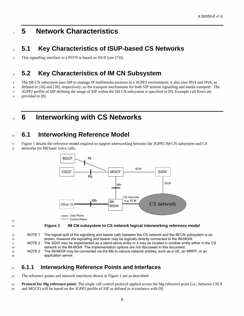
Figure 1 details the reference model required to support interworking between the 3GPP2 IM CN subsystem and CS 11
networks for IM basic voice calls. 12
(Note 3)
CSCF
CS network IM- MGW
MGCF SGW
Mb CS channelse.g. PCM
ISUP Mn
User Plane Control Plane
ISUP
Mg
BGCF Mj
13
Figure 1 IM CN subsystem to CS network logical interworking reference model 14
NOTE 1 The logical split of the signalling and bearer path between the CS network and the IM CN subsystem is as 15
shown, however the signalling and bearer may be logically directly connected to the IM-MGW. 16
NOTE 2 The SGW may be implemented as a stand-alone entity or it may be located in another entity either in the CS 17
network or the IM-MGW. The implementation options are not discussed in this document. 18
NOTE 3 The IM-MGW may be connected via the Mb to various network entities, such as a UE, an MRFP, or an 19
application server. 20
6.1.1 Interworking Reference Points and Interfaces 21
The reference points and network interfaces shown in Figure 1 are as described: 22
Protocol for Mg reference point: The single call control protocol applied across the Mg reference point (i.e., between CSCF 23
and MGCF) will be based on the 3GPP2 profile of SIP as defined in accordance with [9]. 24
X.S0050-0 v1.0
7
Protocol for Mn reference point: The Mn reference point describes the interfaces between the MGCF and IM-MGW, and 1
will be based on the profile of H.248 protocol defined in [33]. 2
Protocol for Mj reference point: The single call control protocol applied across the Mj reference point (i.e., between BGCF 3
and MGCF) will be based on the 3GPP2 profile of SIP as defined in accordance with [9]. 4
Protocol for Mb reference point: The Mb reference point is an IP bearer facility (IPv4 or IPv6). 5
6.1.2 Interworking Functional Entities 6
6.1.2.1 Void 7
6.1.2.2 Media Gateway Control Function (MGCF) 8
This is the component within the IM CN subsystem, which controls the IM-MGW, and also performs the SIP to ISUP call 9
related signalling interworking. 10
The functionality defined within MGCF shall be defined in accordance with [7]. 11
6.1.2.3 IP Multimedia - Media Gateway Function (IM-MGW) 12
This is the component within the IM CN subsystem, that provides the interface between the PS domain and the CS domain, 13
and it shall support the functions as defined in accordance with [7]. 14
6.2 Control Plane Interworking Model 15
Within the IM CN subsystem, the 3GPP2 profile of SIP is used to originate and terminate IM sessions to and from the UE. 16
External CS networks use ISUP to originate and terminate voice calls to and from the IM CN subsystem. 17
Therefore, in order to provide the required interworking to enable inter network session control, the control plane protocols 18
shall be interworked within the IM CN subsystem. This function is performed within the MGCF (see clause 6.1.2). 19
6.3 User Plane Interworking Model 20
Within the IM CN subsystem, IPv4/IPv6, and framing protocols such as RTP, are used to transport media packets to and 21
from the IM CN subsystem entity like UE or MRFP. 22
External legacy CS networks use circuit switched bearer channels like TDM circuits (e.g., 64 kbit/s PCM) or IP bearers to 23
carry encoded voice frames, to and from the IM CN subsystem. 24
Therefore, in order to provide the required interworking to enable media data exchange, the user plane protocols shall be 25
translated within the IM CN subsystem. This function is performed within the IM-MGW (see clause 6.1.2). 26
7 Control Plane Interworking 27
Signalling between CS networks and the IM CN subsystem, where the associated supported signalling protocols are SS7 and 28
IP, requires a level of interworking between the nodes across the Control Plane, i.e., the SS7 signalling function, MGCF and 29
SIP signalling function. This interworking is required in order to provide a seamless support of a user part, i.e., SIP and 30
ISUP. 31
X.S0050-0 v1.0
8
7.1 General 1
The following sub-clauses define the signalling interworking between the ISDN User Part (ISUP) protocols and Session 2
Initiation Protocol (SIP) with its associated Session Description Protocol (SDP) at a MGCF. The MGCF shall act as a 3
Type A exchange ([73]) for the purposes of ISUP procedures. The services that can be supported through the use of the 4
signalling interworking are limited to the services that are supported by ISUP and SIP based network domains. 5
The ISUP capabilities or signalling information defined for national use may be found in an annex to this document. 6
The capabilities of SIP and SDP that are interworked with ISUP are defined in [9]. Any interworking of ISUP messages or 7
SIP methods not mentioned in this document is for further study. 8
Services that are common in SIP and ISUP network domains will seamlessly interwork by using the function of the MGCF. 9
The MGCF will originate and/or terminate services or capabilities that do not interwork seamlessly across domains according 10
to the relevant protocol recommendation or specification. 11
Table 1 lists the services seamlessly interworked and therefore are within the scope of this document. 12
Table 1 Interworking Capabilities between ISUP and SIP profile for 3GPP2 13
Service
Speech/3.1 kHz audio
En bloc address signalling
Inband transport of DTMF tones and information.
Calling Line Identification Presentation (CLIP)
Calling Line Identification Restriction (CLIR)
7.2 Interworking between CS Networks Supporting ISUP and the 14
IM CN Subsystem 15
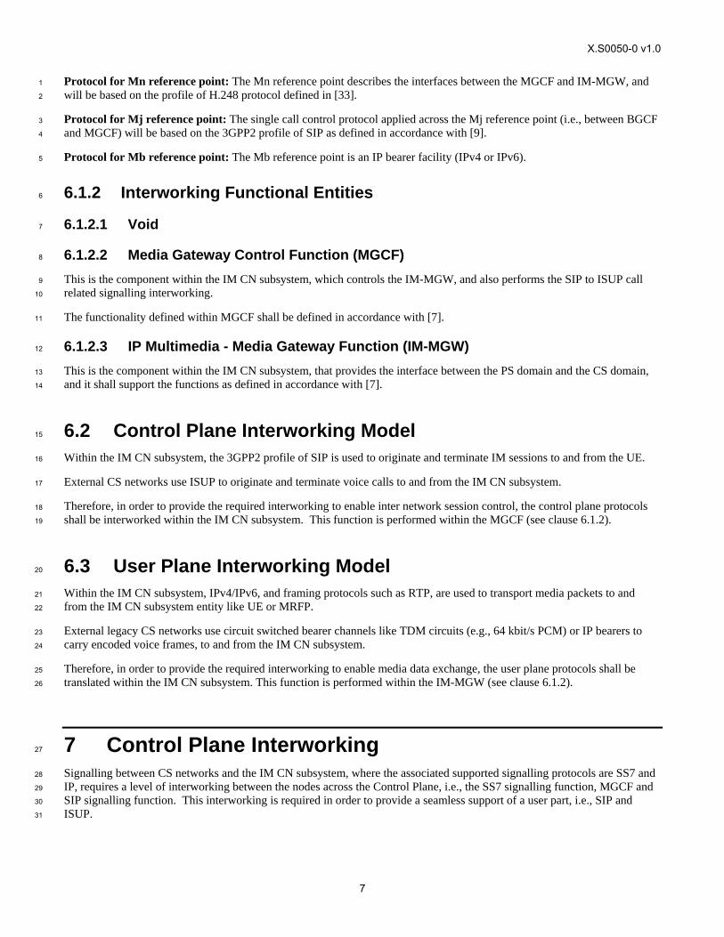
The control plane supports ISUP in the CS networks and SIP in the IM CN subsystem. One example of how this may be 16
achieved is shown in Figure 2. 17
S S 7 s ign a llin gfu n ctio n
M ed ia ga tew ayco n tro l fu nc tio n
S IP s ign a llin gfu n ctio n
S IP
IP
IS U P
T C P / U D P /S C T P
IP
T C P / U D P /S C T P
S IPIS U P
IP
IS U P S IP
L o w er L a y er
L o w er L a ye r
18
Figure 2 Control plane Interworking between CS Networks Supporting ISUP and the IM CN Subsystem 19
7.2.1 Services Performed by Network Entities in the Control Plane 20
7.2.1.1 Services Performed by the SS7 Signalling Function 21
The SS7 signalling function provides the capabilities to deliver or receive ISUP signalling messages across the SS7 signalling 22
network. 23
X.S0050-0 v1.0
9
7.2.1.2 Void 1
7.2.1.3 Services of the MGCF 2
The session handling and session control of the MGCF shall be as detailed in [9]. 3
The MGCF interworking function shall provide the interaction and translation between the ISUP and SIP, where the 4
interworking of SIP to ISUP is detailed below. 5
7.2.1.4 Services of the SIP Signalling Function 6
The SIP signalling function is a logical entity that provides the capabilities to deliver or receive multimedia session 7
information across the IM CN subsystem signalling system. 8
7.2.2 Signalling Between Network Entities in the Control Plane 9
7.2.2.1 Signalling Between the SS7 Signalling Function and the MGCF 10
ISUP signalling messages are exchanged between the SS7 signalling function and the MGCF. The lower layer translation 11
between the two entities for those signalling messages is outside of the scope of this document. 12
7.2.2.2 Signalling Between the MGCF and SIP Signalling Function 13
Signalling between the SIP signalling function and the MGCF uses the services of IP [39], and a transport protocol such as 14
TCP [24], UDP [17], SCTP [18], plus SIP (see [9] and [19]). 15
The naming and addressing concepts between the MGCF and SIP signalling function shall be detailed in accordance with [7]. 16
7.2.3 SIP-ISUP protocol interworking 17
When a coding of a parameter value is omitted it implies that it is not affected by the interworking, and the values are 18
assigned by normal protocol procedures. 19
7.2.3.1 Incoming Call Interworking from SIP to ISUP at I-MGCF 20
7.2.3.1.1 Sending of IAM 21
On reception of a SIP INVITE requesting an audio session or with an empty SDP, the I-MGCF shall send an IAM message. 22
An I-MGCF shall support both incoming INVITE requests containing SIP preconditions and 100rel extensions in the SIP 23
Supported or Require headers, and INVITE requests not containing these extensions, unless the Note below applies. 24
NOTE: If the I-MGCF is deployed in an IMS network that by local configuration serves no user requiring 25
preconditions, the MGCF may not support incoming requests requiring preconditions. 26
The I-MGCF shall interwork forked INVITE requests with different request URIs. 27
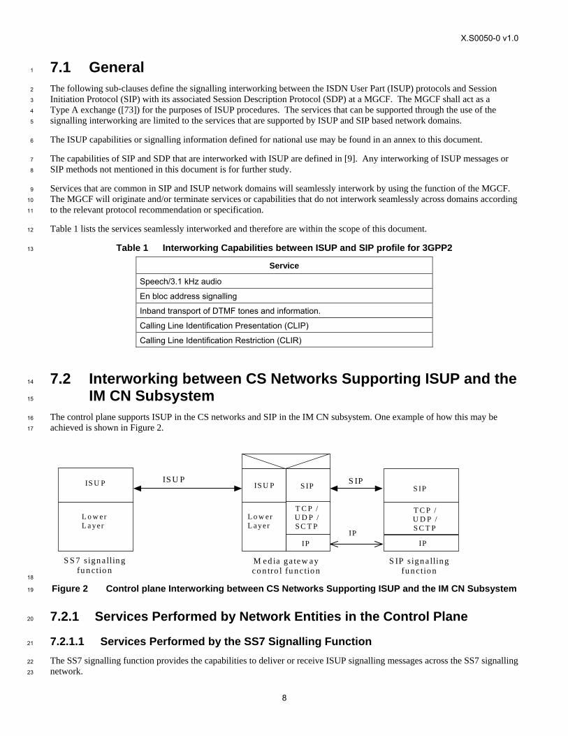
If a Continuity Check procedure is supported in the ISUP network, the I-MGCF shall send the IAM immediately after the 28
reception of the INVITE, as shown in Figure 3. This procedure applies when the value of the continuity indicator is either set 29
to “continuity check required” or “continuity check performed on a previous circuit”. If the continuity indicator is set to 30
“continuity check required” the corresponding procedures at the Mn interface described in clause 9.2.2.3 also apply. 31
X.S0050-0 v1.0
10
1
Figure 3 Receipt of an Invite Request (Continuity Procedure Supported in the ISUP Network) 2
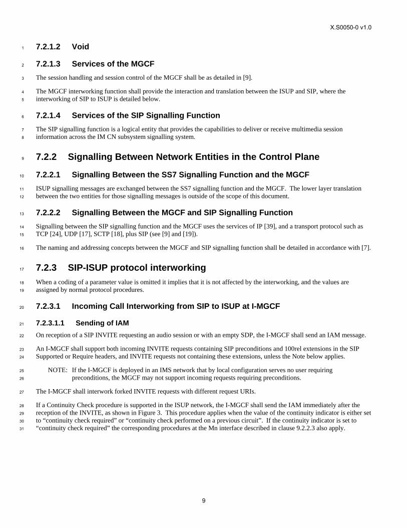
If no Continuity Check procedure is supported in the ISUP network, and the SDP in the received INVITE request contains 3
preconditions not met, the I-MGCF shall delay sending the IAM until the SIP preconditions are met. 4
I-MGCF
INVITE
IAM
SDP indicating pre-conditions met
5
Figure 4 Receipt of an Invite request (continuity procedure not supported in the ISUP network) 6
The I-MGCF shall reject an INVITE request for a session only containing unsupported media or codec types by sending a 7
status code 488 “Not Acceptable Here”. If several media streams are contained in a single INVITE request, the I-MGCF 8
shall select one of the supported media streams, reserve the codec(s) for that media stream, and reject the other media streams 9
and unselected codecs in the SDP answer, as detailed in [36]. If supported audio media stream(s) and supported non-audio 10
media stream(s) are contained in a single INVITE request, an audio stream shall be selected. 11
The I-MGCF shall include a To tag in the first backward non-100 provisional response, in order to establish an early dialog 12
as described in [19]. 13
If the INVITE message is received without an SDP (offer), then the I-MGCF shall send an SDP (offer) in the first reliable 14
non-failure message as per [19] and [36]. 15
7.2.3.1.2 Coding of the IAM 16
The following ISDN user part parameters description can be found in [73]. 17
7.2.3.1.2.1 Called Party Number 18
The E.164 address encoded in the Request-URI shall be mapped to the called party number parameter of the IAM message. 19
X.S0050-0 v1.0
11
Table 2 Coding of the Called Party Number 1
INVITE→ IAM→
Request-URI Called Party Number
Address Signal: Analyse the information contained in received E.164 address. If CC is country code of the network in which the next hop terminates, then remove “+CC” and use the remaining digits to fill the Address signals. If CC is not the country code of the network in which the next hop terminates, then remove “+” and use the remaining digits to fill the Address signals.
Odd/even indicator: set as required
Nature of address indicator: Analyse the information contained in received E.164 address. If CC is country code of the network in which the next hop terminates, then set Nature of Address indicator to “National (significant) number. If CC is not the country code of the network in which the next hop terminates, then set Nature of Address indicator to “International number”.
E.164 address (format +CC NDC SN) (This address is either: - the geographical number in the userinfo if routing number parameter does not exist in the userinfo - the routing number if the routing number parameter exists in the userinfo)
Numbering plan Indicator: 001 ISDN (Telephony) numbering plan (Rec. E.164) 2
If the routing number parameter (following “rn=”) (as defined in [72]) is not present in the userinfo component of the 3
Request-URI, the geographic telephone number (e.g., as User info in SIP URI with user=phone, or as tel URL) shall be 4
mapped to the Called Party Number parameter of the IAM as described in Table 2. 5
If the routing number parameter is present in the userinfo component of the Request-URI, the routing number parameter 6
contained in the userinfo of the Request-URI shall be mapped to the Called Party Number parameter of the IAM. The 7
geographic number in this case shall be mapped to the Generic Address (GAP) of the IAM, the GAP’s Type of Address in 8
this case is set to “ported number”. 9
7.2.3.1.2.2 Nature of Connection Indicators 10
bits BA Satellite indicator 11
0 1 one satellite circuit in the connection 12
bits DC Continuity check indicator 13
0 0 continuity check not required, if the continuity check procedure is not supported in the succeeding 14
network (Figure 4) 15
0 1 continuity check required, if a continuity check shall be carried out on the succeeding circuit. (Figure 3) 16
1 0 continuity check performed on a previous circuit otherwise, if the continuity check procedure is 17
supported in the succeeding network, but shall not be carried out on the succeeding circuit otherwise. 18
(Figure 3) 19
bit E Echo control device indicator 20
1 outgoing echo control device included 21
7.2.3.1.2.3 Forward Call Indicators 22
bits CB End-to-end method indicator 23
0 0 no end-to-end method available (only link-by-link method available) 24
bit D Interworking indicator 25
1 interworking encountered 26
bit F ISDN user part indicator 27
X.S0050-0 v1.0
12
0 ISDN user part not used all the way 1
bits HG ISDN user part preference indicator 2
0 1 ISDN user part not required all the way 3
bit I ISDN access indicator 4
0 originating access non-ISDN 5
bits KJ SCCP method indicator 6
0 0 no indication 7
bit M Ported number translation indicator 8
0 number not translated 9
1 number translated 10
The value M = 1 “number translated” is used if an NP Database Dip Indicator (npdi) parameter (as defined in [72]) 11
is present in the userinfo component of the Request-URI. 12
7.2.3.1.2.4 Calling Party's Category 13
0 0 0 0 1 0 1 0 ordinary calling subscriber 14
7.2.3.1.2.5 User Service Information 15
As a network option, either: 16
1) The USI parameter is set to 3.1 kHz audio and transcoding is applied when required (e.g., for 3GPP networks); or 17
2) If no SDP is received from the remote peer, the USI parameter fields are set as follows: Information Transfer 18
Capability is set to 3.1 kHz audio; Information Transfer Rate is set to 64 kbit/s; and the User Information Layer 1 19
Protocol is set to G.711 µ-law. Transcoding is applied as required. If SDP is received from the remote peer before 20
the IAM is sent and if transcoding is not supported at the I-MGCF, then the User Service Information (USI) 21
parameter shall be derived from the SDP as described below and in Table 3. Otherwise they shall be set in 22
accordance with local policy. 23
The I-MGCF may either transcode the selected codec(s) to the codec on the PSTN side or it may attempt to interwork the 24
media without transcoding. If the I-MGCF does not transcode, it should map the USI and Access Transport parameters from 25
the selected codec according to Table 3. The support of any of the media listed in Table 3 other than audio, is optional. 26
The SDP Media Description Part received by the I-MGCF should indicate only one media stream. 27
Only the “m=”, “b=”, and “a=” lines of the SDP Media Description Part are considered to interwork with the IAM USI and 28
HLC parameters. 29
The first sub-field (i.e., <media> of the “m=” line will indicate one of the currently defined values “audio”, “video”, 30
“application”, “data”, “image”, or “control”. 31
Further studies are needed if <media> of the “m=” line is “video”, “application”, “data” or “control”. 32
If the round-up bandwidth of <media> equal to audio is 64 kbps or the “b=” line is absent, then USI should be set to 33
“3.1 kHz”, and the <transport> and <fmt-list> are evaluated to determine whether User information layer 1 protocol indicator 34
of USI parameter should be set to “G.711 mu-law” or “G.711 A-law”. 35
X.S0050-0 v1.0
13
Table 3 Coding of USI/HLC from SDP: SIP to ISUP 1
m= line b= line (NOTE 4) a= line USI parameter (Note 1) HLC parameter (optional)
<media> <transport> <fmt-list> <modifier>:<bandwidth-value> (NOTE 5)
rtpmap:<dynamic-PT> <encoding name>/<clock rate>[/encoding parameters>
Information Transfer Rate
Information Transport Capability
User Information
Layer 1 Protocol Indicator
High Layer Characteristics Identification
audio RTP/AVP 0 N/A or up to 64 kbit/s N/A 64 kbit/s “3.1KHz audio” “G.711 µ-law” (NOTE 3)
audio RTP/AVP Dynamic PT N/A or up to 64 kbit/s rtpmap:<dynamic-PT> PCMU/8000
64 kbit/s “3.1KHz audio” “G.711 µ-law” (NOTE 3)
audio RTP/AVP 9 AS: 64 kbit/s rtpmap:9 G722/8000 64 kbit/s “Unrestricted digital inf. w/tones/ann”
audio RTP/AVP Dynamic PT AS: 64 kbit/s rtpmap:<dynamic-PT> CLEARMODE/8000 (NOTE 2)
64 kbit/s “Unrestricted digital information”
image udptl t38 N/A or up to 64 kbit/s Based on T.38 64 kbit/s “3.1KHz audio” “Facsímile Group 2/3”
image tcptl t38 N/A or up to 64 kbit/s Based on T.38 64 kbit/s “3.1KHz audio” “Facsímile Group 2/3”
NOTE 1 In this table the codec G.711 is used only as an example. Other codecs are possible. NOTE 2 CLEARMODE is specified in [69]. NOTE 3 HLC is normally absent in this case. It is possible for HLC to be present with the value “Telephony”, although [85], Clause 4.5.5, indicates that this would
normally be accompanied by a value of “Speech” for the Information Transfer Capability element. NOTE 4 If the b=line indicates a bandwidth greater than 64kbit/s then the call may use compression techniques or reject the call with a 415 response indicating that
only one media stream of 64kbit/s is supported. NOTE 5 <bandwidth value> for <modifier> of AS is in units of kbit/s.
2
X.S0050-0 v1.0
14
7.2.3.1.2.6 Calling Party Number 1
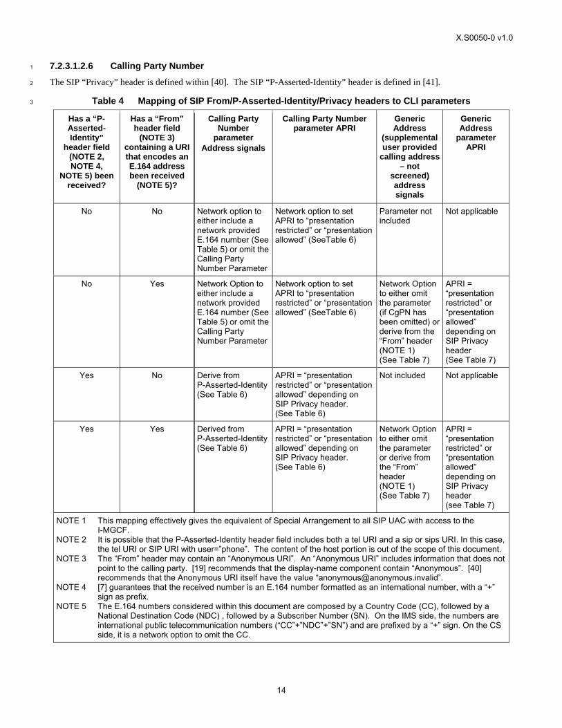
The SIP “Privacy” header is defined within [40]. The SIP “P-Asserted-Identity” header is defined in [41]. 2
Table 4 Mapping of SIP From/P-Asserted-Identity/Privacy headers to CLI parameters 3
Has a “P-Asserted-Identity”
header field (NOTE 2, NOTE 4,
NOTE 5) been received?
Has a “From” header field
(NOTE 3) containing a URI that encodes an E.164 address been received
(NOTE 5)?
Calling Party Number
parameter Address signals
Calling Party Number parameter APRI
Generic Address
(supplemental user provided
calling address – not
screened) address signals
Generic Address
parameter APRI
No No Network option to either include a network provided E.164 number (See Table 5) or omit the Calling Party Number Parameter
Network option to set APRI to “presentation restricted” or “presentation allowed” (SeeTable 6)
Parameter not included
Not applicable
No Yes Network Option to either include a network provided E.164 number (See Table 5) or omit the Calling Party Number Parameter
Network option to set APRI to “presentation restricted” or “presentation allowed” (SeeTable 6)
Network Option to either omit the parameter (if CgPN has been omitted) or derive from the “From” header (NOTE 1) (See Table 7)
APRI = “presentation restricted” or “presentation allowed” depending on SIP Privacy header (See Table 7)
Yes No Derive from P-Asserted-Identity (See Table 6)
APRI = “presentation restricted” or “presentation allowed” depending on SIP Privacy header. (See Table 6)
Not included Not applicable
Yes Yes Derived from P-Asserted-Identity (See Table 6)
APRI = “presentation restricted” or “presentation allowed” depending on SIP Privacy header. (See Table 6)
Network Option to either omit the parameter or derive from the “From” header (NOTE 1) (See Table 7)
APRI = “presentation restricted” or “presentation allowed” depending on SIP Privacy header (see Table 7)
NOTE 1 This mapping effectively gives the equivalent of Special Arrangement to all SIP UAC with access to the I-MGCF.
NOTE 2 It is possible that the P-Asserted-Identity header field includes both a tel URI and a sip or sips URI. In this case, the tel URI or SIP URI with user=”phone”. The content of the host portion is out of the scope of this document.
NOTE 3 The “From” header may contain an “Anonymous URI”. An “Anonymous URI” includes information that does not point to the calling party. [19] recommends that the display-name component contain “Anonymous”. [40] recommends that the Anonymous URI itself have the value “[email protected]”.
NOTE 4 [7] guarantees that the received number is an E.164 number formatted as an international number, with a “+” sign as prefix.
NOTE 5 The E.164 numbers considered within this document are composed by a Country Code (CC), followed by a National Destination Code (NDC) , followed by a Subscriber Number (SN). On the IMS side, the numbers are international public telecommunication numbers (“CC”+”NDC”+”SN”) and are prefixed by a “+” sign. On the CS side, it is a network option to omit the CC.
X.S0050-0 v1.0
15
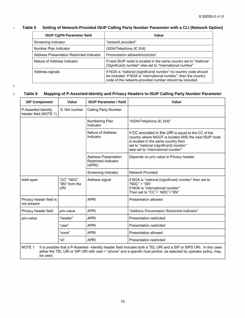
Table 5 Setting of Network-Provided ISUP Calling Party Number Parameter with a CLI (Network Option) 1
ISUP CgPN Parameter field Value
Screening Indicator “network provided”
Number Plan Indicator ISDN/Telephony (E.164)
Address Presentation Restricted Indicator Presentation allowed/restricted
Nature of Address Indicator If next ISUP node is located in the same country set to “National (Significant) number” else set to “International number”
Address signals If NOA is “national (significant) number” no country code should be included. If NOA is “international number”, then the country code of the network-provided number should be included.
2
Table 6 Mapping of P-Asserted-Identity and Privacy Headers to ISUP Calling Party Number Parameter 3
SIP Component Value ISUP Parameter / field Value
P-Asserted-Identity header field (NOTE 1)
E.164 number Calling Party Number
Numbering Plan Indicator
“ISDN/Telephony (E.164)”
Nature of Address Indicator
If CC encoded in the URI is equal to the CC of the country where MGCF is located AND the next ISUP node is located in the same country then set to “national (significant) number” else set to “international number”
Address Presentation Restricted Indicator (APRI)
Depends on priv-value in Privacy header.
Screening indicator Network Provided
Addr-spec “CC” “NDC” “SN” from the URI
Address signal if NOA is “national (significant) number” then set to “NDC” + “SN” If NOA is “international number” Then set to “CC”+” NDC”+”SN”
Privacy header field is not present
APRI Presentation allowed
Privacy header field priv-value APRI “Address Presentation Restricted Indicator”
“header” APRI Presentation restricted
“user” APRI Presentation restricted
“none” APRI Presentation allowed
priv-value
“id” APRI Presentation restricted
NOTE 1 It is possible that a P-Asserted –Identity header field includes both a TEL URI and a SIP or SIPS URI. In this case, either the TEL URI or SIP URI with user = “phone” and a specific host portion, as selected by operator policy, may be used.
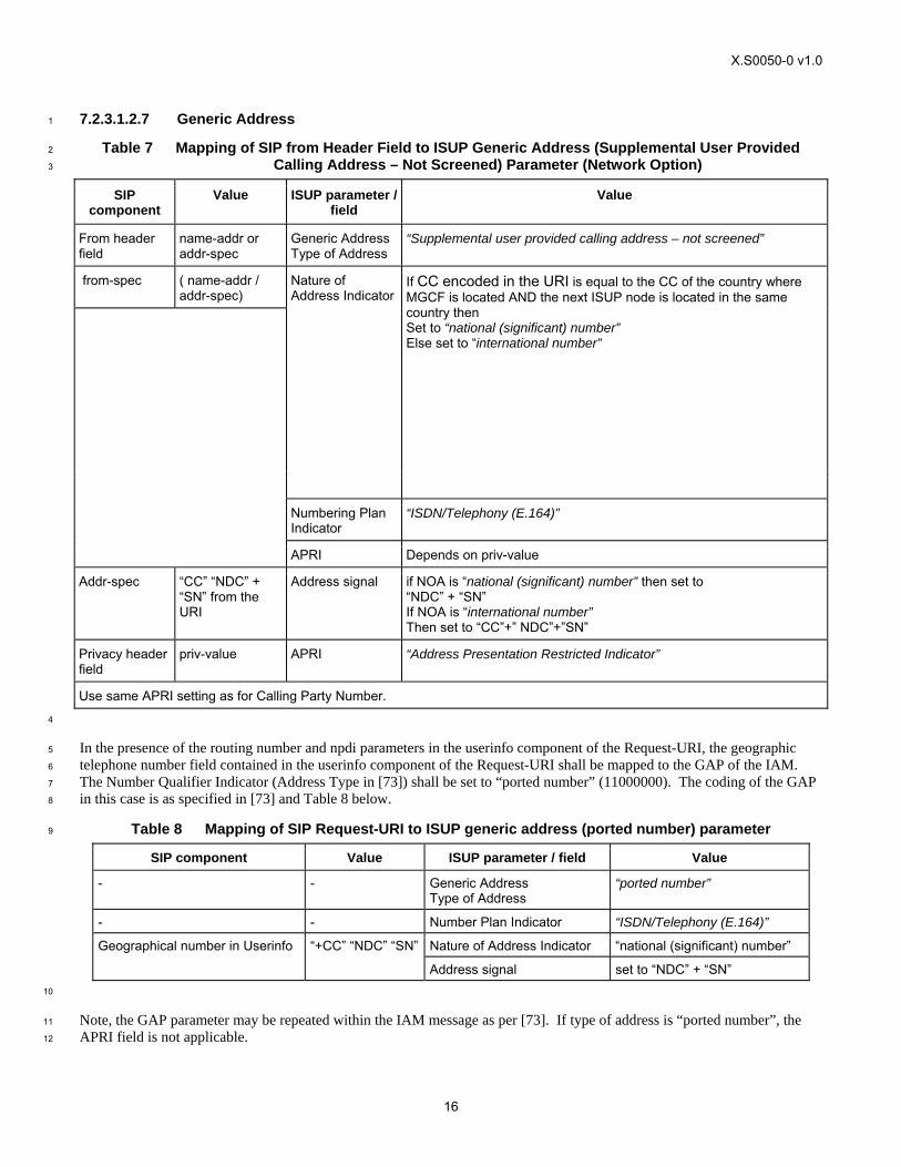
X.S0050-0 v1.0
16
7.2.3.1.2.7 Generic Address 1
Table 7 Mapping of SIP from Header Field to ISUP Generic Address (Supplemental User Provided 2
Calling Address – Not Screened) Parameter (Network Option) 3
SIP component
Value ISUP parameter / field
Value
From header field
name-addr or addr-spec
Generic Address Type of Address
“Supplemental user provided calling address – not screened”
from-spec ( name-addr / addr-spec)
Nature of Address Indicator
If CC encoded in the URI is equal to the CC of the country where MGCF is located AND the next ISUP node is located in the same country then Set to “national (significant) number” Else set to “international number”
Numbering Plan Indicator
“ISDN/Telephony (E.164)”
APRI Depends on priv-value
Addr-spec “CC” “NDC” + “SN” from the URI
Address signal if NOA is “national (significant) number” then set to “NDC” + “SN” If NOA is “international number” Then set to “CC”+” NDC”+”SN”
Privacy header field
priv-value APRI “Address Presentation Restricted Indicator”
Use same APRI setting as for Calling Party Number. 4
In the presence of the routing number and npdi parameters in the userinfo component of the Request-URI, the geographic 5
telephone number field contained in the userinfo component of the Request-URI shall be mapped to the GAP of the IAM. 6
The Number Qualifier Indicator (Address Type in [73]) shall be set to “ported number” (11000000). The coding of the GAP 7
in this case is as specified in [73] and Table 8 below. 8
Table 8 Mapping of SIP Request-URI to ISUP generic address (ported number) parameter 9
SIP component Value ISUP parameter / field Value
- - Generic Address Type of Address
“ported number”
- - Number Plan Indicator “ISDN/Telephony (E.164)”
Nature of Address Indicator “national (significant) number” Geographical number in Userinfo “+CC” “NDC” “SN”
Address signal set to “NDC” + “SN” 10
Note, the GAP parameter may be repeated within the IAM message as per [73]. If type of address is “ported number”, the 11
APRI field is not applicable. 12
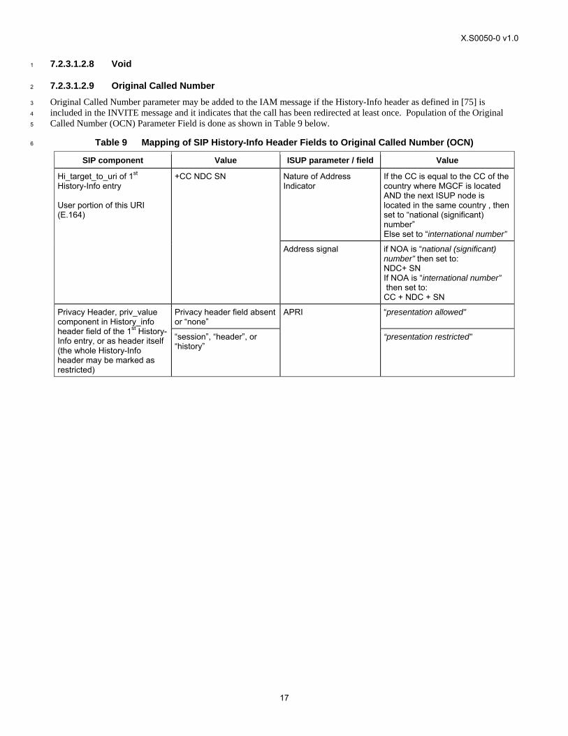
X.S0050-0 v1.0
17
7.2.3.1.2.8 Void 1
7.2.3.1.2.9 Original Called Number 2
Original Called Number parameter may be added to the IAM message if the History-Info header as defined in [75] is 3
included in the INVITE message and it indicates that the call has been redirected at least once. Population of the Original 4
Called Number (OCN) Parameter Field is done as shown in Table 9 below. 5
Table 9 Mapping of SIP History-Info Header Fields to Original Called Number (OCN) 6
SIP component Value ISUP parameter / field Value
Nature of Address Indicator
If the CC is equal to the CC of the country where MGCF is located AND the next ISUP node is located in the same country , then set to “national (significant) number” Else set to “international number”
Hi_target_to_uri of 1st History-Info entry User portion of this URI (E.164)
+CC NDC SN
Address signal if NOA is “national (significant) number” then set to: NDC+ SN If NOA is “international number” then set to: CC + NDC + SN
Privacy header field absent or “none”
“presentation allowed” Privacy Header, priv_value component in History_info header field of the 1st History-Info entry, or as header itself (the whole History-Info header may be marked as restricted)
“session”, “header”, or “history”
APRI
“presentation restricted”
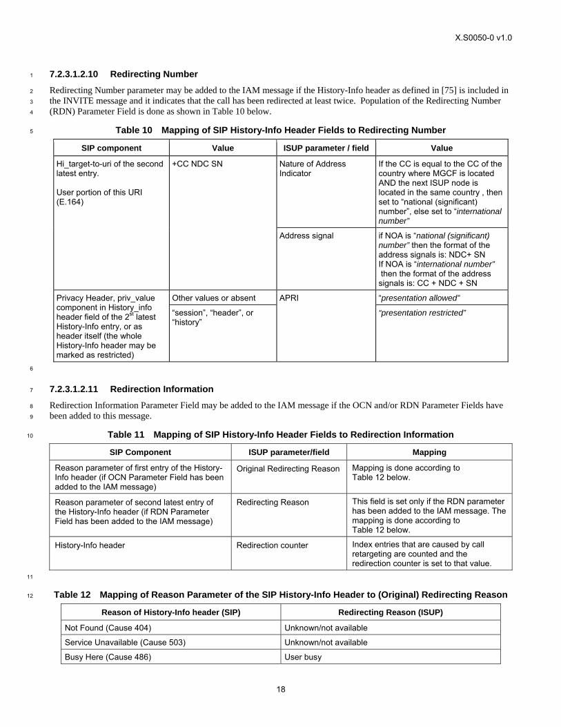
X.S0050-0 v1.0
18
7.2.3.1.2.10 Redirecting Number 1
Redirecting Number parameter may be added to the IAM message if the History-Info header as defined in [75] is included in 2
the INVITE message and it indicates that the call has been redirected at least twice. Population of the Redirecting Number 3
(RDN) Parameter Field is done as shown in Table 10 below. 4
Table 10 Mapping of SIP History-Info Header Fields to Redirecting Number 5
SIP component Value ISUP parameter / field Value
Nature of Address Indicator
If the CC is equal to the CC of the country where MGCF is located AND the next ISUP node is located in the same country , then set to “national (significant) number”, else set to “international number”
Hi_target-to-uri of the second latest entry. User portion of this URI (E.164)
+CC NDC SN
Address signal if NOA is “national (significant) number” then the format of the address signals is: NDC+ SN If NOA is “international number” then the format of the address signals is: CC + NDC + SN
Other values or absent “presentation allowed” Privacy Header, priv_value component in History_info header field of the 2st latest History-Info entry, or as header itself (the whole History-Info header may be marked as restricted)
“session”, “header”, or “history”
APRI
“presentation restricted”
6
7.2.3.1.2.11 Redirection Information 7
Redirection Information Parameter Field may be added to the IAM message if the OCN and/or RDN Parameter Fields have 8
been added to this message. 9
Table 11 Mapping of SIP History-Info Header Fields to Redirection Information 10
SIP Component ISUP parameter/field Mapping
Reason parameter of first entry of the History-Info header (if OCN Parameter Field has been added to the IAM message)
Original Redirecting Reason Mapping is done according to Table 12 below.
Reason parameter of second latest entry of the History-Info header (if RDN Parameter Field has been added to the IAM message)
Redirecting Reason This field is set only if the RDN parameter has been added to the IAM message. The mapping is done according to Table 12 below.
History-Info header Redirection counter Index entries that are caused by call retargeting are counted and the redirection counter is set to that value.
11
Table 12 Mapping of Reason Parameter of the SIP History-Info Header to (Original) Redirecting Reason 12
Reason of History-Info header (SIP) Redirecting Reason (ISUP)
Not Found (Cause 404) Unknown/not available
Service Unavailable (Cause 503) Unknown/not available
Busy Here (Cause 486) User busy
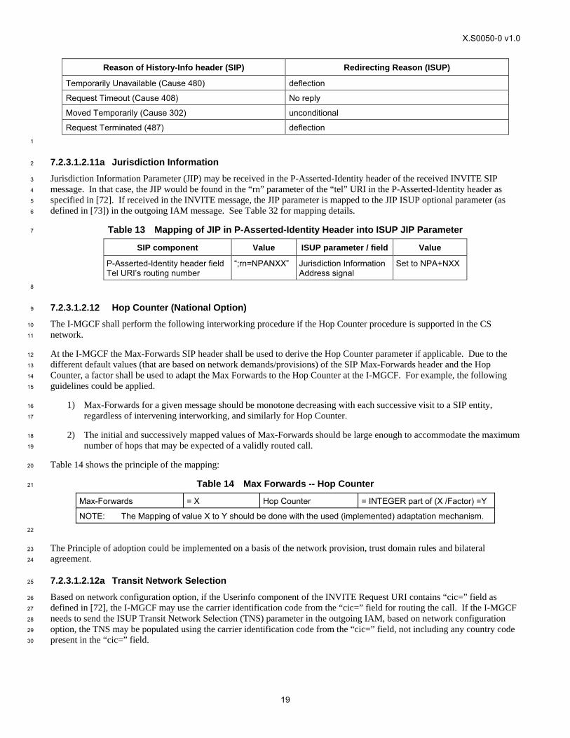
X.S0050-0 v1.0
19
Reason of History-Info header (SIP) Redirecting Reason (ISUP)
Temporarily Unavailable (Cause 480) deflection
Request Timeout (Cause 408) No reply
Moved Temporarily (Cause 302) unconditional
Request Terminated (487) deflection 1
7.2.3.1.2.11a Jurisdiction Information 2
Jurisdiction Information Parameter (JIP) may be received in the P-Asserted-Identity header of the received INVITE SIP 3
message. In that case, the JIP would be found in the “rn” parameter of the “tel” URI in the P-Asserted-Identity header as 4
specified in [72]. If received in the INVITE message, the JIP parameter is mapped to the JIP ISUP optional parameter (as 5
defined in [73]) in the outgoing IAM message. See Table 32 for mapping details. 6
Table 13 Mapping of JIP in P-Asserted-Identity Header into ISUP JIP Parameter 7
SIP component Value ISUP parameter / field Value
P-Asserted-Identity header field Tel URI’s routing number
“;rn=NPANXX” Jurisdiction Information Address signal
Set to NPA+NXX
8
7.2.3.1.2.12 Hop Counter (National Option) 9
The I-MGCF shall perform the following interworking procedure if the Hop Counter procedure is supported in the CS 10
network. 11
At the I-MGCF the Max-Forwards SIP header shall be used to derive the Hop Counter parameter if applicable. Due to the 12
different default values (that are based on network demands/provisions) of the SIP Max-Forwards header and the Hop 13
Counter, a factor shall be used to adapt the Max Forwards to the Hop Counter at the I-MGCF. For example, the following 14
guidelines could be applied. 15
1) Max-Forwards for a given message should be monotone decreasing with each successive visit to a SIP entity, 16
regardless of intervening interworking, and similarly for Hop Counter. 17
2) The initial and successively mapped values of Max-Forwards should be large enough to accommodate the maximum 18
number of hops that may be expected of a validly routed call. 19
Table 14 shows the principle of the mapping: 20
Table 14 Max Forwards -- Hop Counter 21
Max-Forwards = X Hop Counter = INTEGER part of (X /Factor) =Y
NOTE: The Mapping of value X to Y should be done with the used (implemented) adaptation mechanism. 22
The Principle of adoption could be implemented on a basis of the network provision, trust domain rules and bilateral 23
agreement. 24
7.2.3.1.2.12a Transit Network Selection 25
Based on network configuration option, if the Userinfo component of the INVITE Request URI contains “cic=” field as 26
defined in [72], the I-MGCF may use the carrier identification code from the “cic=” field for routing the call. If the I-MGCF 27
needs to send the ISUP Transit Network Selection (TNS) parameter in the outgoing IAM, based on network configuration 28
option, the TNS may be populated using the carrier identification code from the “cic=” field, not including any country code 29
present in the “cic=” field. 30
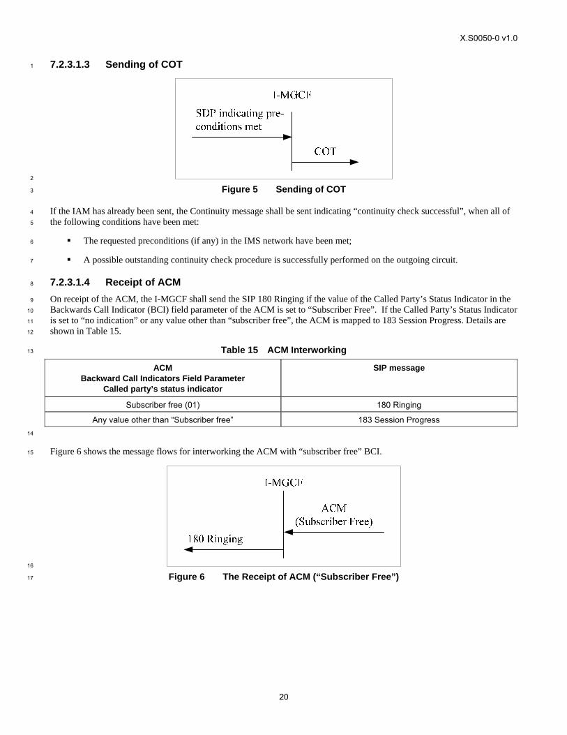
X.S0050-0 v1.0
20
7.2.3.1.3 Sending of COT 1
2
Figure 5 Sending of COT 3
If the IAM has already been sent, the Continuity message shall be sent indicating “continuity check successful”, when all of 4
the following conditions have been met: 5
The requested preconditions (if any) in the IMS network have been met; 6
A possible outstanding continuity check procedure is successfully performed on the outgoing circuit. 7
7.2.3.1.4 Receipt of ACM 8
On receipt of the ACM, the I-MGCF shall send the SIP 180 Ringing if the value of the Called Party’s Status Indicator in the 9
Backwards Call Indicator (BCI) field parameter of the ACM is set to “Subscriber Free”. If the Called Party’s Status Indicator 10
is set to “no indication” or any value other than “subscriber free”, the ACM is mapped to 183 Session Progress. Details are 11
shown in Table 15. 12
Table 15 ACM Interworking 13
ACM Backward Call Indicators Field Parameter
Called party’s status indicator
SIP message
Subscriber free (01) 180 Ringing
Any value other than “Subscriber free” 183 Session Progress 14
Figure 6 shows the message flows for interworking the ACM with “subscriber free” BCI. 15
16
Figure 6 The Receipt of ACM (“Subscriber Free”) 17
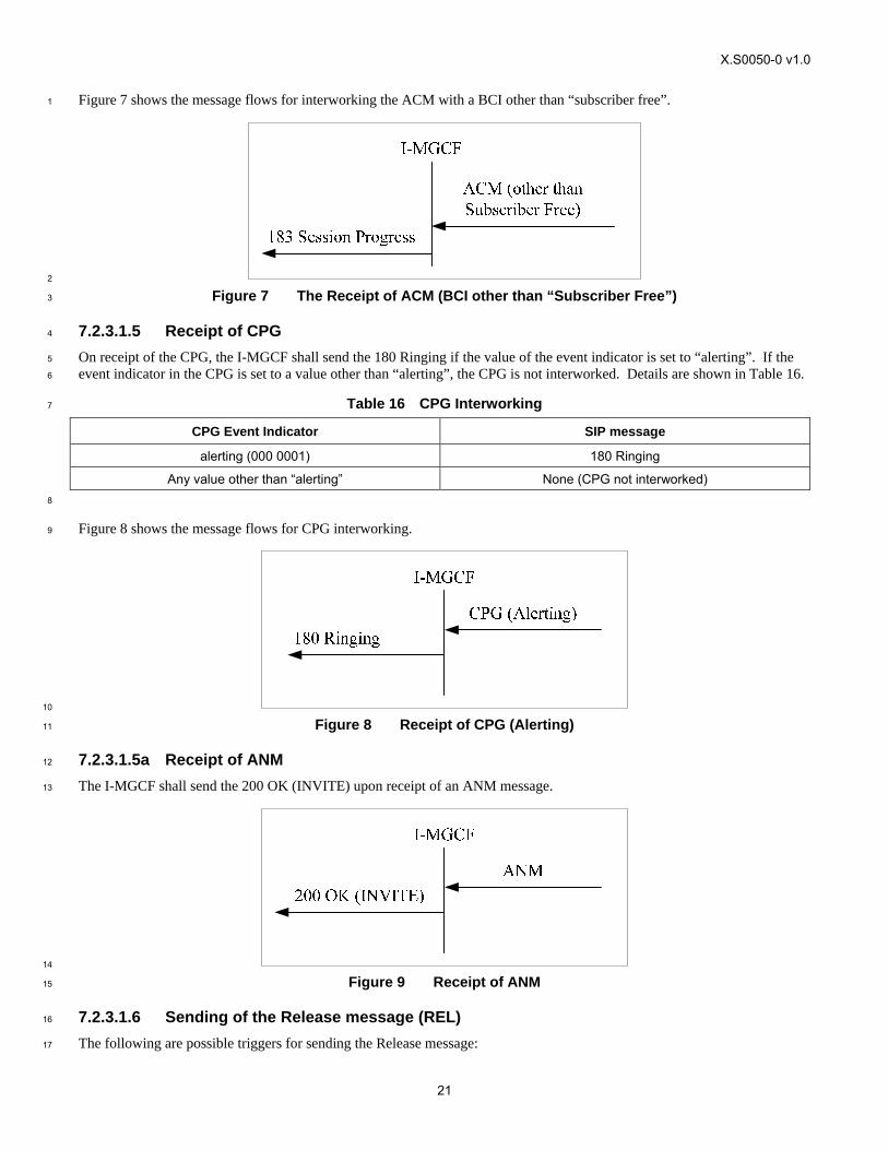
X.S0050-0 v1.0
21
Figure 7 shows the message flows for interworking the ACM with a BCI other than “subscriber free”. 1
2
Figure 7 The Receipt of ACM (BCI other than “Subscriber Free”) 3
7.2.3.1.5 Receipt of CPG 4
On receipt of the CPG, the I-MGCF shall send the 180 Ringing if the value of the event indicator is set to “alerting”. If the 5
event indicator in the CPG is set to a value other than “alerting”, the CPG is not interworked. Details are shown in Table 16. 6
Table 16 CPG Interworking 7
CPG Event Indicator SIP message
alerting (000 0001) 180 Ringing
Any value other than “alerting” None (CPG not interworked) 8
Figure 8 shows the message flows for CPG interworking. 9
10
Figure 8 Receipt of CPG (Alerting) 11
7.2.3.1.5a Receipt of ANM 12
The I-MGCF shall send the 200 OK (INVITE) upon receipt of an ANM message. 13
14
Figure 9 Receipt of ANM 15
7.2.3.1.6 Sending of the Release message (REL) 16
The following are possible triggers for sending the Release message: 17
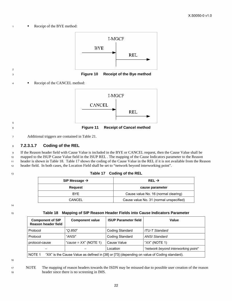
X.S0050-0 v1.0
22
Receipt of the BYE method: 1
2
Figure 10 Receipt of the Bye method 3
Receipt of the CANCEL method: 4
5
Figure 11 Receipt of Cancel method 6
Additional triggers are contained in Table 21. 7
7.2.3.1.7 Coding of the REL 8
If the Reason header field with Cause Value is included in the BYE or CANCEL request, then the Cause Value shall be 9
mapped to the ISUP Cause Value field in the ISUP REL . The mapping of the Cause Indicators parameter to the Reason 10
header is shown in Table 18. Table 17 shows the coding of the Cause Value in the REL if it is not available from the Reason 11
header field. In both cases, the Location Field shall be set to “network beyond interworking point”. 12
Table 17 Coding of the REL 13
SIP Message REL
Request cause parameter
BYE Cause value No. 16 (normal clearing)
CANCEL Cause value No. 31 (normal unspecified) 14
Table 18 Mapping of SIP Reason Header Fields into Cause Indicators Parameter 15
Component of SIP Reason header field
Component value ISUP Parameter field Value
Protocol “Q.850” Coding Standard ITU-T Standard
Protocol “ANSI” Coding Standard ANSI Standard
protocol-cause “cause = XX” (NOTE 1) Cause Value “XX” (NOTE 1)
– – Location “network beyond interworking point”
NOTE 1 “XX” is the Cause Value as defined in [38] or [73] (depending on value of Coding standard). 16
NOTE The mapping of reason headers towards the ISDN may be misused due to possible user creation of the reason 17
header since there is no screening in IMS. 18
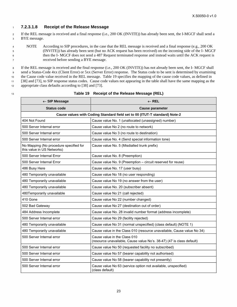
X.S0050-0 v1.0
23
7.2.3.1.8 Receipt of the Release Message 1
If the REL message is received and a final response (i.e., 200 OK (INVITE)) has already been sent, the I-MGCF shall send a 2
BYE message. 3
NOTE According to SIP procedures, in the case that the REL message is received and a final response (e.g., 200 OK 4
(INVITE)) has already been sent (but no ACK request has been received) on the incoming side of the I- MGCF 5
then the I- MGCF does not send a 487 Request terminated response and instead waits until the ACK request is 6
received before sending a BYE message. 7
If the REL message is received and the final response (i.e., 200 OK (INVITE)) has not already been sent, the I- MGCF shall 8
send a Status-Code 4xx (Client Error) or 5xx (Server Error) response. The Status code to be sent is determined by examining 9
the Cause code value received in the REL message. Table 19 specifies the mapping of the cause code values, as defined in 10
[38] and [73], to SIP response status codes. Cause code values not appearing in the table shall have the same mapping as the 11
appropriate class defaults according to [38] and [73]. 12
Table 19 Receipt of the Release Message (REL) 13
← SIP Message ← REL
Status code Cause parameter
Cause values with Coding Standard field set to 00 (ITUT-T standard) Note-2 404 Not Found Cause value No. 1 (unallocated (unassigned) number)
500 Server Internal error Cause value No 2 (no route to network)
500 Server Internal error Cause value No 3 (no route to destination)
500 Server Internal error Cause value No. 4 (Send special information tone)
No Mapping (No procedure specified for this value in US Networks)
Cause value No. 5 (Misdialled trunk prefix)
500 Server Internal Error Cause value No. 8 (Preemption)
500 Server Internal Error Cause value No. 9 (Preemption – circuit reserved for reuse)
486 Busy Here Cause value No. 17 (user busy)
480 Temporarily unavailable Cause value No 18 (no user responding)
480 Temporarily unavailable Cause value No 19 (no answer from the user)
480 Temporarily unavailable Cause value No. 20 (subscriber absent)
480Temporarily unavailable Cause value No 21 (call rejected)
410 Gone Cause value No 22 (number changed)
502 Bad Gateway Cause value No 27 (destination out of order)
484 Address Incomplete Cause value No. 28 invalid number format (address incomplete)
500 Server Internal error Cause value No 29 (facility rejected)
480 Temporarily unavailable Cause value No 31 (normal unspecified) (class default) (NOTE 1)
480 Temporarily unavailable Cause value in the Class 010 (resource unavailable, Cause value No 34)
500 Server Internal error Cause value in the Class 010 (resource unavailable, Cause value No’s. 38-47) (47 is class default)
500 Server Internal error Cause value No 50 (requested facility no subscribed)
500 Server Internal error Cause value No 57 (bearer capability not authorised)
500 Server Internal error Cause value No 58 (bearer capability not presently)
500 Server Internal error Cause value No 63 (service option not available, unspecified) (class default)
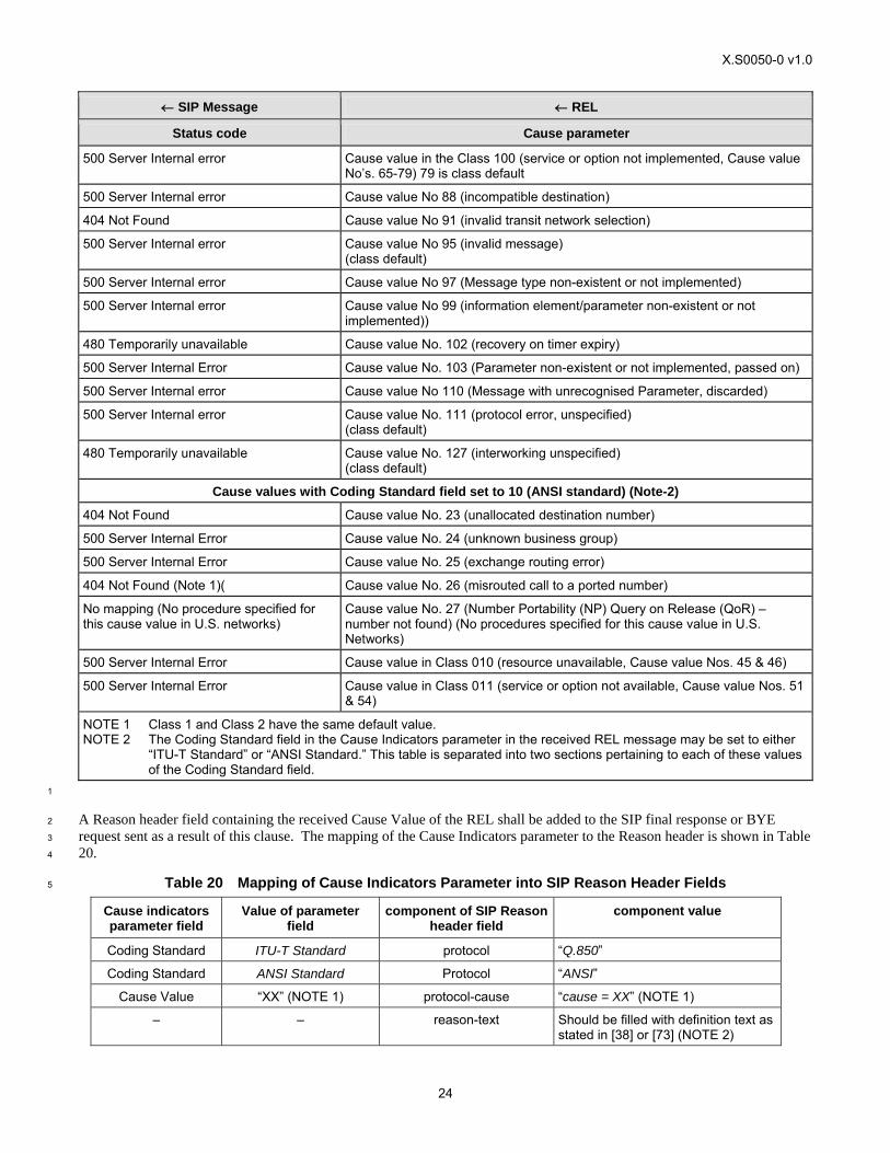
X.S0050-0 v1.0
24
← SIP Message ← REL
Status code Cause parameter
500 Server Internal error Cause value in the Class 100 (service or option not implemented, Cause value No’s. 65-79) 79 is class default
500 Server Internal error Cause value No 88 (incompatible destination)
404 Not Found Cause value No 91 (invalid transit network selection)
500 Server Internal error Cause value No 95 (invalid message) (class default)
500 Server Internal error Cause value No 97 (Message type non-existent or not implemented)
500 Server Internal error Cause value No 99 (information element/parameter non-existent or not implemented))
480 Temporarily unavailable Cause value No. 102 (recovery on timer expiry)
500 Server Internal Error Cause value No. 103 (Parameter non-existent or not implemented, passed on)
500 Server Internal error Cause value No 110 (Message with unrecognised Parameter, discarded)
500 Server Internal error Cause value No. 111 (protocol error, unspecified) (class default)
480 Temporarily unavailable Cause value No. 127 (interworking unspecified) (class default)
Cause values with Coding Standard field set to 10 (ANSI standard) (Note-2)
404 Not Found Cause value No. 23 (unallocated destination number)
500 Server Internal Error Cause value No. 24 (unknown business group)
500 Server Internal Error Cause value No. 25 (exchange routing error)
404 Not Found (Note 1)( Cause value No. 26 (misrouted call to a ported number)
No mapping (No procedure specified for this cause value in U.S. networks)
Cause value No. 27 (Number Portability (NP) Query on Release (QoR) – number not found) (No procedures specified for this cause value in U.S. Networks)
500 Server Internal Error Cause value in Class 010 (resource unavailable, Cause value Nos. 45 & 46)
500 Server Internal Error Cause value in Class 011 (service or option not available, Cause value Nos. 51 & 54)
NOTE 1 Class 1 and Class 2 have the same default value. NOTE 2 The Coding Standard field in the Cause Indicators parameter in the received REL message may be set to either
“ITU-T Standard” or “ANSI Standard.” This table is separated into two sections pertaining to each of these values of the Coding Standard field.
1
A Reason header field containing the received Cause Value of the REL shall be added to the SIP final response or BYE 2
request sent as a result of this clause. The mapping of the Cause Indicators parameter to the Reason header is shown in Table 3
20. 4
Table 20 Mapping of Cause Indicators Parameter into SIP Reason Header Fields 5
Cause indicators parameter field
Value of parameter field
component of SIP Reason header field
component value
Coding Standard ITU-T Standard protocol “Q.850”
Coding Standard ANSI Standard Protocol “ANSI”
Cause Value “XX” (NOTE 1) protocol-cause “cause = XX” (NOTE 1)
– – reason-text Should be filled with definition text as stated in [38] or [73] (NOTE 2)
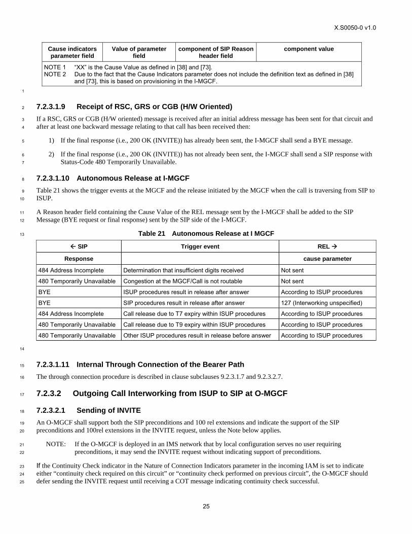
X.S0050-0 v1.0
25
Cause indicators parameter field
Value of parameter field
component of SIP Reason header field
component value
NOTE 1 “XX” is the Cause Value as defined in [38] and [73]. NOTE 2 Due to the fact that the Cause Indicators parameter does not include the definition text as defined in [38]
and [73], this is based on provisioning in the I-MGCF. 1
7.2.3.1.9 Receipt of RSC, GRS or CGB (H/W Oriented) 2
If a RSC, GRS or CGB (H/W oriented) message is received after an initial address message has been sent for that circuit and 3
after at least one backward message relating to that call has been received then: 4
1) If the final response (i.e., 200 OK (INVITE)) has already been sent, the I-MGCF shall send a BYE message. 5
2) If the final response (i.e., 200 OK (INVITE)) has not already been sent, the I-MGCF shall send a SIP response with 6
Status-Code 480 Temporarily Unavailable. 7
7.2.3.1.10 Autonomous Release at I-MGCF 8
Table 21 shows the trigger events at the MGCF and the release initiated by the MGCF when the call is traversing from SIP to 9
ISUP. 10
A Reason header field containing the Cause Value of the REL message sent by the I-MGCF shall be added to the SIP 11
Message (BYE request or final response) sent by the SIP side of the I-MGCF. 12
Table 21 Autonomous Release at I MGCF 13
SIP Trigger event REL
Response cause parameter
484 Address Incomplete Determination that insufficient digits received Not sent
480 Temporarily Unavailable Congestion at the MGCF/Call is not routable Not sent
BYE ISUP procedures result in release after answer According to ISUP procedures
BYE SIP procedures result in release after answer 127 (Interworking unspecified)
484 Address Incomplete Call release due to T7 expiry within ISUP procedures According to ISUP procedures
480 Temporarily Unavailable Call release due to T9 expiry within ISUP procedures According to ISUP procedures
480 Temporarily Unavailable Other ISUP procedures result in release before answer According to ISUP procedures
14
7.2.3.1.11 Internal Through Connection of the Bearer Path 15
The through connection procedure is described in clause subclauses 9.2.3.1.7 and 9.2.3.2.7. 16
7.2.3.2 Outgoing Call Interworking from ISUP to SIP at O-MGCF 17
7.2.3.2.1 Sending of INVITE 18
An O-MGCF shall support both the SIP preconditions and 100 rel extensions and indicate the support of the SIP 19
preconditions and 100rel extensions in the INVITE request, unless the Note below applies. 20
NOTE: If the O-MGCF is deployed in an IMS network that by local configuration serves no user requiring 21
preconditions, it may send the INVITE request without indicating support of preconditions. 22
If the Continuity Check indicator in the Nature of Connection Indicators parameter in the incoming IAM is set to indicate 23
either “continuity check required on this circuit” or “continuity check performed on previous circuit”, the O-MGCF should 24
defer sending the INVITE request until receiving a COT message indicating continuity check successful. 25
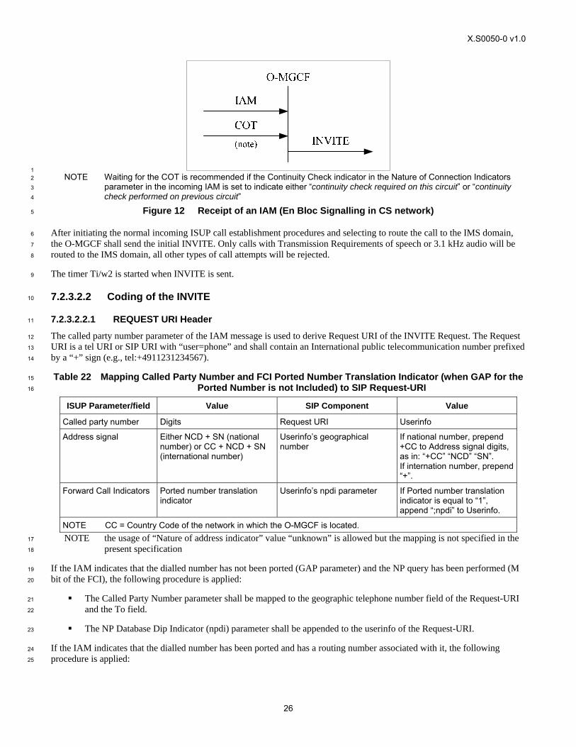
X.S0050-0 v1.0
26
1 NOTE Waiting for the COT is recommended if the Continuity Check indicator in the Nature of Connection Indicators 2
parameter in the incoming IAM is set to indicate either “continuity check required on this circuit” or “continuity 3
check performed on previous circuit” 4
Figure 12 Receipt of an IAM (En Bloc Signalling in CS network) 5
After initiating the normal incoming ISUP call establishment procedures and selecting to route the call to the IMS domain, 6
the O-MGCF shall send the initial INVITE. Only calls with Transmission Requirements of speech or 3.1 kHz audio will be 7
routed to the IMS domain, all other types of call attempts will be rejected. 8
The timer Ti/w2 is started when INVITE is sent. 9
7.2.3.2.2 Coding of the INVITE 10
7.2.3.2.2.1 REQUEST URI Header 11
The called party number parameter of the IAM message is used to derive Request URI of the INVITE Request. The Request 12
URI is a tel URI or SIP URI with “user=phone” and shall contain an International public telecommunication number prefixed 13
by a “+” sign (e.g., tel:+4911231234567). 14
Table 22 Mapping Called Party Number and FCI Ported Number Translation Indicator (when GAP for the 15
Ported Number is not Included) to SIP Request-URI 16
ISUP Parameter/field Value SIP Component Value
Called party number Digits Request URI Userinfo
Address signal Either NCD + SN (national number) or CC + NCD + SN (international number)
Userinfo’s geographical number
If national number, prepend +CC to Address signal digits, as in: “+CC” “NCD” “SN”. If internation number, prepend “+”.
Forward Call Indicators Ported number translation indicator
Userinfo’s npdi parameter If Ported number translation indicator is equal to “1”, append “;npdi” to Userinfo.
NOTE CC = Country Code of the network in which the O-MGCF is located. NOTE the usage of “Nature of address indicator” value “unknown” is allowed but the mapping is not specified in the 17
present specification 18
If the IAM indicates that the dialled number has not been ported (GAP parameter) and the NP query has been performed (M 19
bit of the FCI), the following procedure is applied: 20
The Called Party Number parameter shall be mapped to the geographic telephone number field of the Request-URI 21
and the To field. 22
The NP Database Dip Indicator (npdi) parameter shall be appended to the userinfo of the Request-URI. 23
If the IAM indicates that the dialled number has been ported and has a routing number associated with it, the following 24
procedure is applied: 25
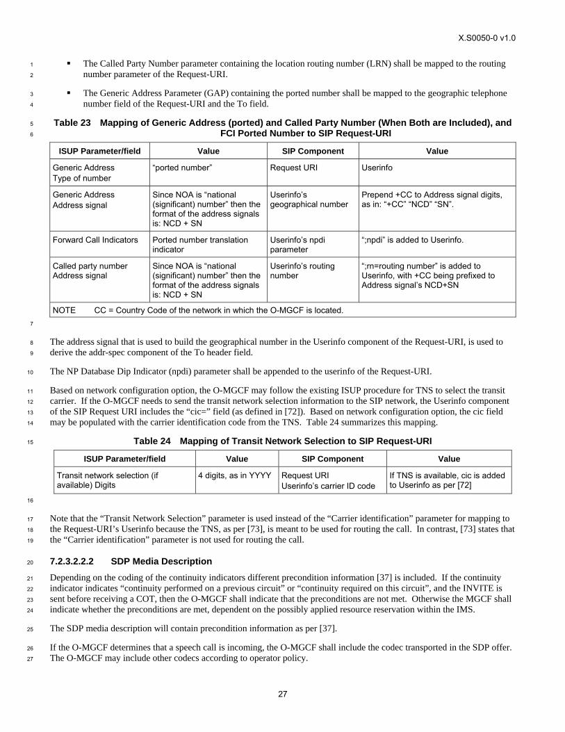
X.S0050-0 v1.0
27
The Called Party Number parameter containing the location routing number (LRN) shall be mapped to the routing 1
number parameter of the Request-URI. 2
The Generic Address Parameter (GAP) containing the ported number shall be mapped to the geographic telephone 3
number field of the Request-URI and the To field. 4
Table 23 Mapping of Generic Address (ported) and Called Party Number (When Both are Included), and 5
FCI Ported Number to SIP Request-URI 6
ISUP Parameter/field Value SIP Component Value
Generic Address Type of number
“ported number” Request URI Userinfo
Generic Address Address signal
Since NOA is “national (significant) number” then the format of the address signals is: NCD + SN
Userinfo’s geographical number
Prepend +CC to Address signal digits, as in: “+CC” “NCD” “SN”.
Forward Call Indicators Ported number translation indicator
Userinfo’s npdi parameter
“;npdi” is added to Userinfo.
Called party number Address signal
Since NOA is “national (significant) number” then the format of the address signals is: NCD + SN
Userinfo’s routing number
“;rn=routing number” is added to Userinfo, with +CC being prefixed to Address signal’s NCD+SN
NOTE CC = Country Code of the network in which the O-MGCF is located. 7
The address signal that is used to build the geographical number in the Userinfo component of the Request-URI, is used to 8
derive the addr-spec component of the To header field. 9
The NP Database Dip Indicator (npdi) parameter shall be appended to the userinfo of the Request-URI. 10
Based on network configuration option, the O-MGCF may follow the existing ISUP procedure for TNS to select the transit 11
carrier. If the O-MGCF needs to send the transit network selection information to the SIP network, the Userinfo component 12
of the SIP Request URI includes the “cic=” field (as defined in [72]). Based on network configuration option, the cic field 13
may be populated with the carrier identification code from the TNS. Table 24 summarizes this mapping. 14
Table 24 Mapping of Transit Network Selection to SIP Request-URI 15
ISUP Parameter/field Value SIP Component Value
Transit network selection (if available) Digits
4 digits, as in YYYY Request URI Userinfo’s carrier ID code
If TNS is available, cic is added to Userinfo as per [72]
16
Note that the “Transit Network Selection” parameter is used instead of the “Carrier identification” parameter for mapping to 17
the Request-URI’s Userinfo because the TNS, as per [73], is meant to be used for routing the call. In contrast, [73] states that 18
the “Carrier identification” parameter is not used for routing the call. 19
7.2.3.2.2.2 SDP Media Description 20
Depending on the coding of the continuity indicators different precondition information [37] is included. If the continuity 21
indicator indicates “continuity performed on a previous circuit” or “continuity required on this circuit”, and the INVITE is 22
sent before receiving a COT, then the O-MGCF shall indicate that the preconditions are not met. Otherwise the MGCF shall 23
indicate whether the preconditions are met, dependent on the possibly applied resource reservation within the IMS. 24
The SDP media description will contain precondition information as per [37]. 25
If the O-MGCF determines that a speech call is incoming, the O-MGCF shall include the codec transported in the SDP offer. 26
The O-MGCF may include other codecs according to operator policy. 27

X.S0050-0 v1.0
28
To avoid transcoding or to support non-speech services, the O-MGCF may add media derived from the incoming ISUP 1
information according to Table 25. The support of the media listed in Table 25 is optional. 2
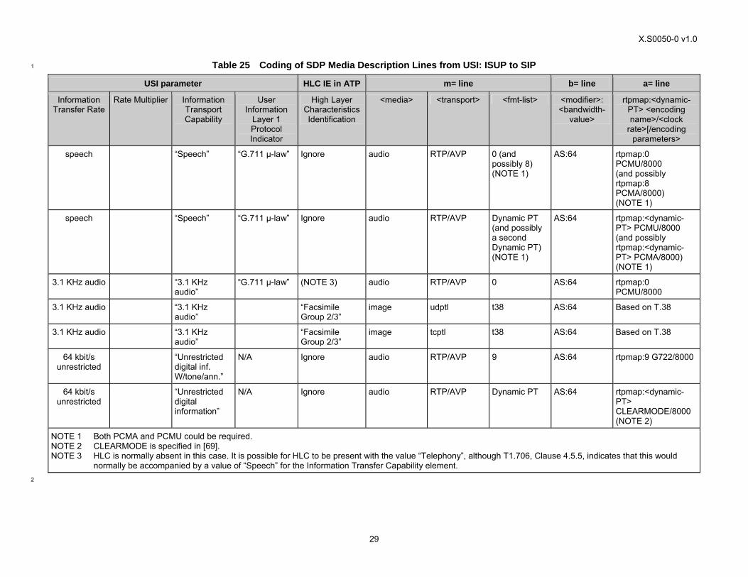
X.S0050-0 v1.0
29
Table 25 Coding of SDP Media Description Lines from USI: ISUP to SIP 1
USI parameter HLC IE in ATP m= line b= line a= line
Information Transfer Rate
Rate Multiplier Information Transport Capability
User Information
Layer 1 Protocol Indicator
High Layer Characteristics Identification
<media> <transport> <fmt-list> <modifier>: <bandwidth-
value>
rtpmap:<dynamic-PT> <encoding name>/<clock
rate>[/encoding parameters>
speech “Speech” “G.711 μ-law” Ignore audio RTP/AVP 0 (and possibly 8) (NOTE 1)
AS:64 rtpmap:0 PCMU/8000 (and possibly rtpmap:8 PCMA/8000) (NOTE 1)
speech “Speech” “G.711 μ-law” Ignore audio RTP/AVP Dynamic PT (and possibly a second Dynamic PT) (NOTE 1)
AS:64 rtpmap:<dynamic-PT> PCMU/8000 (and possibly rtpmap:<dynamic-PT> PCMA/8000) (NOTE 1)
3.1 KHz audio “3.1 KHz audio”
“G.711 μ-law” (NOTE 3) audio RTP/AVP 0 AS:64 rtpmap:0 PCMU/8000
3.1 KHz audio “3.1 KHz audio”
“Facsimile Group 2/3”
image udptl t38 AS:64 Based on T.38
3.1 KHz audio “3.1 KHz audio”
“Facsimile Group 2/3”
image tcptl t38 AS:64 Based on T.38
64 kbit/s unrestricted
“Unrestricted digital inf. W/tone/ann.”
N/A Ignore audio RTP/AVP 9 AS:64 rtpmap:9 G722/8000
64 kbit/s unrestricted
“Unrestricted digital information”
N/A Ignore audio RTP/AVP Dynamic PT AS:64 rtpmap:<dynamic-PT> CLEARMODE/8000 (NOTE 2)
NOTE 1 Both PCMA and PCMU could be required. NOTE 2 CLEARMODE is specified in [69]. NOTE 3 HLC is normally absent in this case. It is possible for HLC to be present with the value “Telephony”, although T1.706, Clause 4.5.5, indicates that this would
normally be accompanied by a value of “Speech” for the Information Transfer Capability element. 2
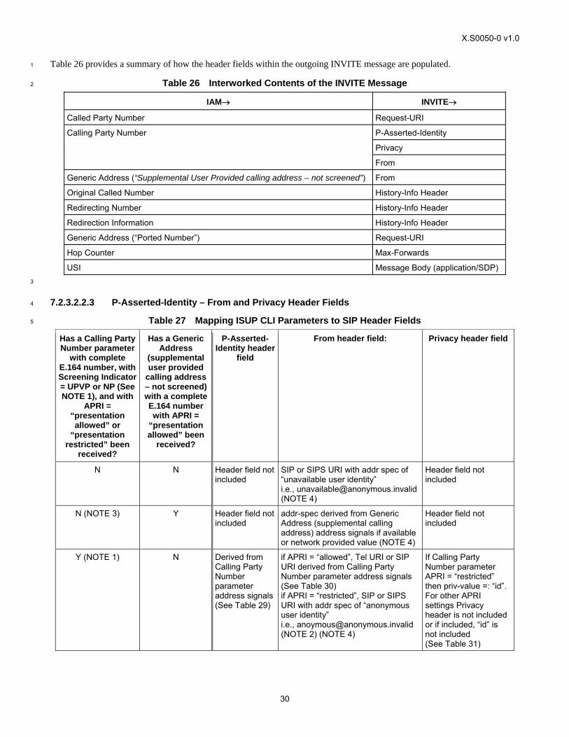
X.S0050-0 v1.0
30
Table 26 provides a summary of how the header fields within the outgoing INVITE message are populated. 1
Table 26 Interworked Contents of the INVITE Message 2
IAM→ INVITE→
Called Party Number Request-URI
P-Asserted-Identity
Privacy
Calling Party Number
From
Generic Address (“Supplemental User Provided calling address – not screened”) From
Original Called Number History-Info Header
Redirecting Number History-Info Header
Redirection Information History-Info Header
Generic Address (“Ported Number”) Request-URI
Hop Counter Max-Forwards
USI Message Body (application/SDP) 3
7.2.3.2.2.3 P-Asserted-Identity – From and Privacy Header Fields 4
Table 27 Mapping ISUP CLI Parameters to SIP Header Fields 5
Has a Calling Party Number parameter
with complete E.164 number, with Screening Indicator = UPVP or NP (See NOTE 1), and with
APRI = “presentation allowed” or
“presentation restricted” been
received?
Has a Generic Address
(supplemental user provided
calling address – not screened) with a complete E.164 number with APRI =
“presentation allowed” been
received?
P-Asserted-Identity header
field
From header field: Privacy header field
N N Header field not included
SIP or SIPS URI with addr spec of “unavailable user identity” i.e., [email protected] (NOTE 4)
Header field not included
N (NOTE 3) Y Header field not included
addr-spec derived from Generic Address (supplemental calling address) address signals if available or network provided value (NOTE 4)
Header field not included
Y (NOTE 1) N Derived from Calling Party Number parameter address signals (See Table 29)
if APRI = “allowed”, Tel URI or SIP URI derived from Calling Party Number parameter address signals (See Table 30) if APRI = “restricted”, SIP or SIPS URI with addr spec of “anonymous user identity” i.e., [email protected] (NOTE 2) (NOTE 4)
If Calling Party Number parameter APRI = “restricted” then priv-value =: “id”. For other APRI settings Privacy header is not included or if included, “id” is not included (See Table 31)
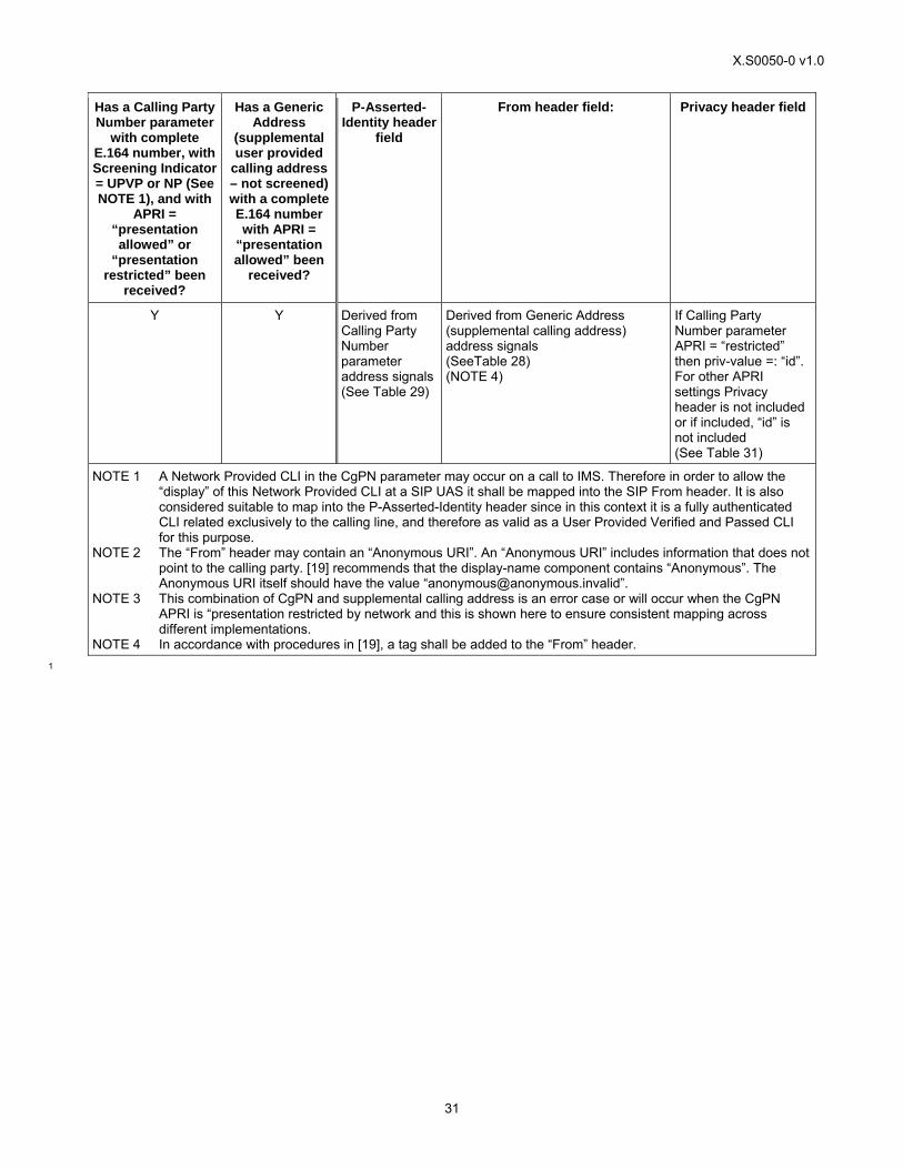
X.S0050-0 v1.0
31
Has a Calling Party Number parameter
with complete E.164 number, with Screening Indicator = UPVP or NP (See NOTE 1), and with
APRI = “presentation allowed” or
“presentation restricted” been
received?
Has a Generic Address
(supplemental user provided
calling address – not screened) with a complete E.164 number with APRI =
“presentation allowed” been
received?
P-Asserted-Identity header
field
From header field: Privacy header field
Y Y Derived from Calling Party Number parameter address signals (See Table 29)
Derived from Generic Address (supplemental calling address) address signals (SeeTable 28) (NOTE 4)
If Calling Party Number parameter APRI = “restricted” then priv-value =: “id”. For other APRI settings Privacy header is not included or if included, “id” is not included (See Table 31)
NOTE 1 A Network Provided CLI in the CgPN parameter may occur on a call to IMS. Therefore in order to allow the “display” of this Network Provided CLI at a SIP UAS it shall be mapped into the SIP From header. It is also considered suitable to map into the P-Asserted-Identity header since in this context it is a fully authenticated CLI related exclusively to the calling line, and therefore as valid as a User Provided Verified and Passed CLI for this purpose.
NOTE 2 The “From” header may contain an “Anonymous URI”. An “Anonymous URI” includes information that does not point to the calling party. [19] recommends that the display-name component contains “Anonymous”. The Anonymous URI itself should have the value “[email protected]”.
NOTE 3 This combination of CgPN and supplemental calling address is an error case or will occur when the CgPN APRI is “presentation restricted by network and this is shown here to ensure consistent mapping across different implementations.
NOTE 4 In accordance with procedures in [19], a tag shall be added to the “From” header. 1
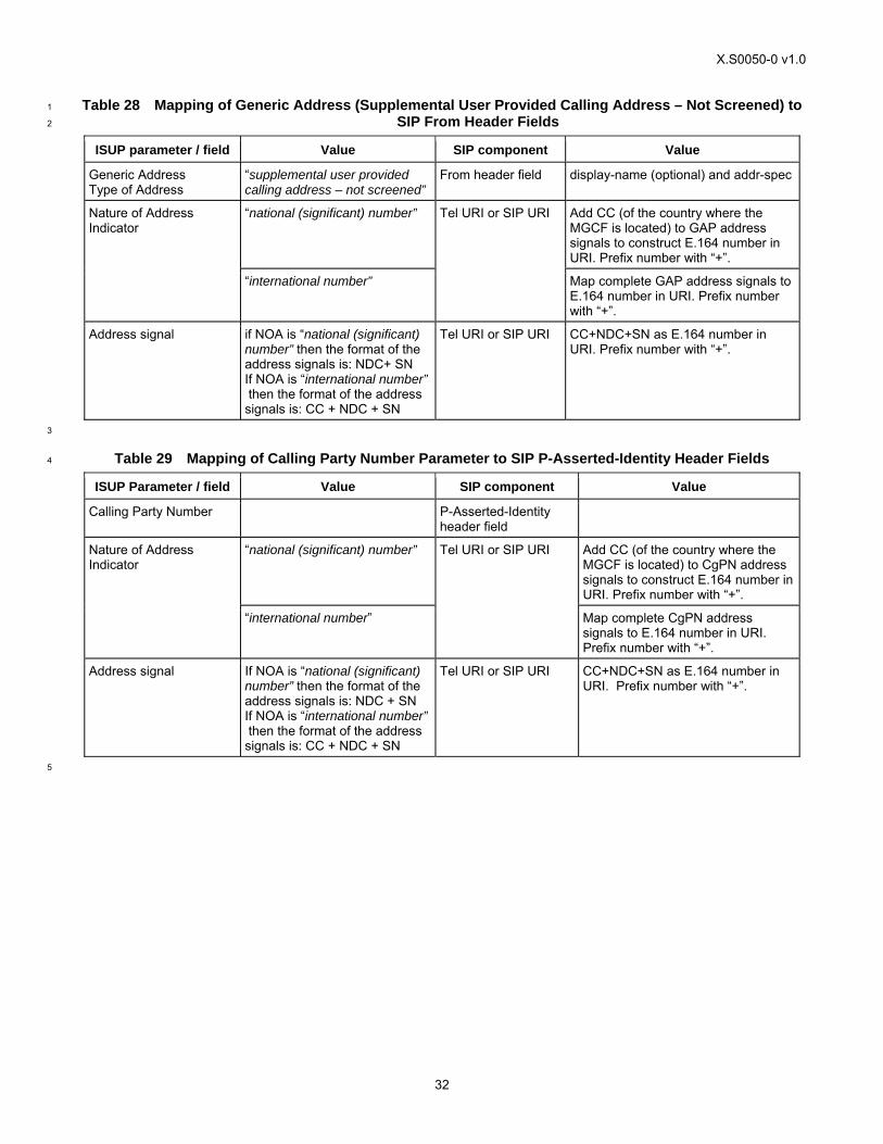
X.S0050-0 v1.0
32
Table 28 Mapping of Generic Address (Supplemental User Provided Calling Address – Not Screened) to 1
SIP From Header Fields 2
ISUP parameter / field Value SIP component Value
Generic Address Type of Address
“supplemental user provided calling address – not screened”
From header field display-name (optional) and addr-spec
“national (significant) number” Add CC (of the country where the MGCF is located) to GAP address signals to construct E.164 number in URI. Prefix number with “+”.
Nature of Address Indicator
“international number”
Tel URI or SIP URI
Map complete GAP address signals to E.164 number in URI. Prefix number with “+”.
Address signal if NOA is “national (significant) number” then the format of the address signals is: NDC+ SN If NOA is “international number” then the format of the address signals is: CC + NDC + SN
Tel URI or SIP URI CC+NDC+SN as E.164 number in URI. Prefix number with “+”.
3
Table 29 Mapping of Calling Party Number Parameter to SIP P-Asserted-Identity Header Fields 4
ISUP Parameter / field Value SIP component Value
Calling Party Number P-Asserted-Identity header field
“national (significant) number” Add CC (of the country where the MGCF is located) to CgPN address signals to construct E.164 number in URI. Prefix number with “+”.
Nature of Address Indicator
“international number”
Tel URI or SIP URI
Map complete CgPN address signals to E.164 number in URI. Prefix number with “+”.
Address signal If NOA is “national (significant) number” then the format of the address signals is: NDC + SN If NOA is “international number” then the format of the address signals is: CC + NDC + SN
Tel URI or SIP URI CC+NDC+SN as E.164 number in URI. Prefix number with “+”.
5
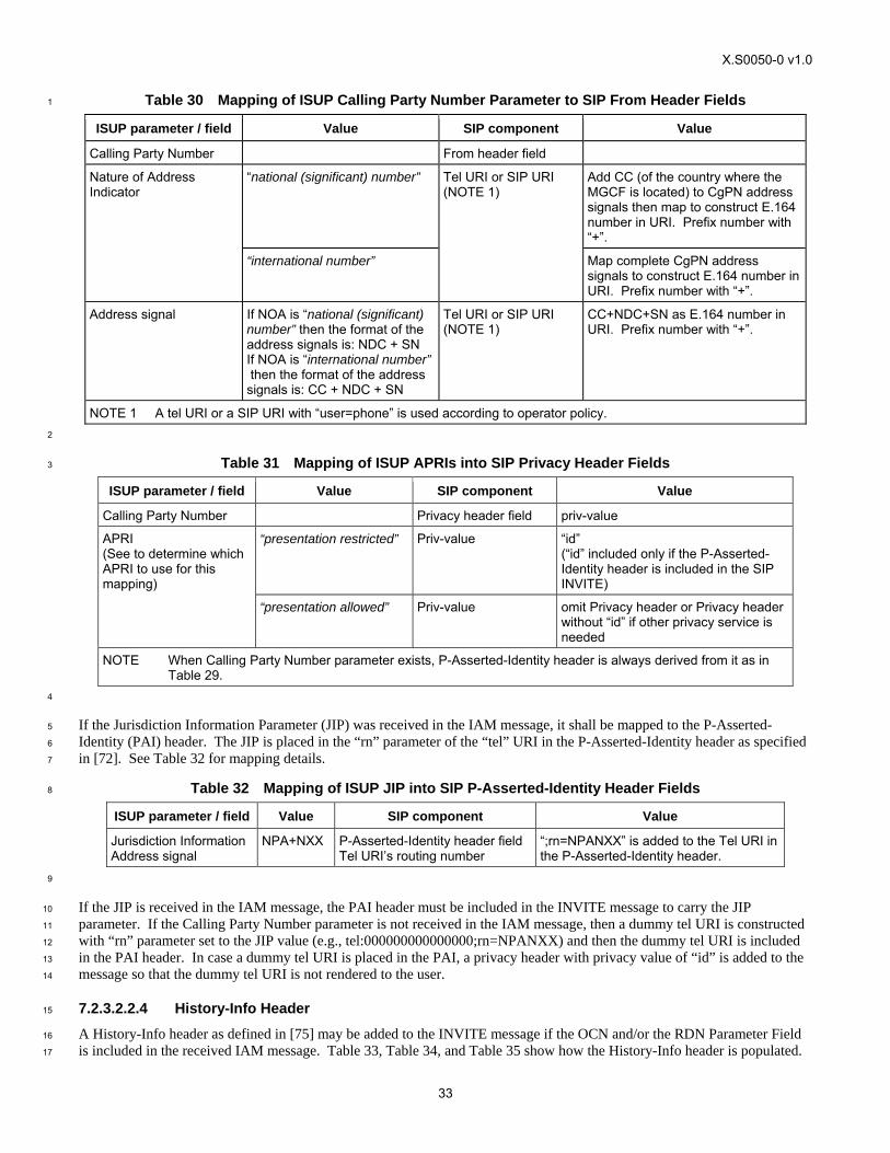
X.S0050-0 v1.0
33
Table 30 Mapping of ISUP Calling Party Number Parameter to SIP From Header Fields 1
ISUP parameter / field Value SIP component Value
Calling Party Number From header field
“national (significant) number” Add CC (of the country where the MGCF is located) to CgPN address signals then map to construct E.164 number in URI. Prefix number with “+”.
Nature of Address Indicator
“international number”
Tel URI or SIP URI (NOTE 1)
Map complete CgPN address signals to construct E.164 number in URI. Prefix number with “+”.
Address signal If NOA is “national (significant) number” then the format of the address signals is: NDC + SN If NOA is “international number” then the format of the address signals is: CC + NDC + SN
Tel URI or SIP URI (NOTE 1)
CC+NDC+SN as E.164 number in URI. Prefix number with “+”.
NOTE 1 A tel URI or a SIP URI with “user=phone” is used according to operator policy. 2
Table 31 Mapping of ISUP APRIs into SIP Privacy Header Fields 3
ISUP parameter / field Value SIP component Value
Calling Party Number Privacy header field priv-value
“presentation restricted” Priv-value “id” (“id” included only if the P-Asserted-Identity header is included in the SIP INVITE)
APRI (See to determine which APRI to use for this mapping)
“presentation allowed” Priv-value omit Privacy header or Privacy header without “id” if other privacy service is needed
NOTE When Calling Party Number parameter exists, P-Asserted-Identity header is always derived from it as in Table 29.
4
If the Jurisdiction Information Parameter (JIP) was received in the IAM message, it shall be mapped to the P-Asserted-5
Identity (PAI) header. The JIP is placed in the “rn” parameter of the “tel” URI in the P-Asserted-Identity header as specified 6
in [72]. See Table 32 for mapping details. 7
Table 32 Mapping of ISUP JIP into SIP P-Asserted-Identity Header Fields 8
ISUP parameter / field Value SIP component Value
Jurisdiction Information Address signal
NPA+NXX P-Asserted-Identity header field Tel URI’s routing number
“;rn=NPANXX” is added to the Tel URI in the P-Asserted-Identity header.
9
If the JIP is received in the IAM message, the PAI header must be included in the INVITE message to carry the JIP 10
parameter. If the Calling Party Number parameter is not received in the IAM message, then a dummy tel URI is constructed 11
with “rn” parameter set to the JIP value (e.g., tel:000000000000000;rn=NPANXX) and then the dummy tel URI is included 12
in the PAI header. In case a dummy tel URI is placed in the PAI, a privacy header with privacy value of “id” is added to the 13
message so that the dummy tel URI is not rendered to the user. 14
7.2.3.2.2.4 History-Info Header 15
A History-Info header as defined in [75] may be added to the INVITE message if the OCN and/or the RDN Parameter Field 16
is included in the received IAM message. Table 33, Table 34, and Table 35 show how the History-Info header is populated. 17
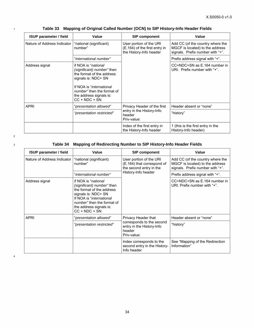
X.S0050-0 v1.0
34
Table 33 Mapping of Original Called Number (OCN) to SIP History-Info Header Fields 1
ISUP parameter / field Value SIP component Value
“national (significant) number”
Add CC (of the country where the MGCF is located) to the address signals. Prefix number with “+”.
Nature of Address Indicator
“international number” Prefix address signal with “+”.
Address signal if NOA is “national (significant) number” then the format of the address signals is: NDC+ SN If NOA is “international number” then the format of the address signals is: CC + NDC + SN
User portion of the URI (E.164) of the first entry in the History-Info header
CC+NDC+SN as E.164 number in URI. Prefix number with “+”.
“presentation allowed” Header absent or “none” APRI
“presentation restricted”
Privacy Header of the first entry in the History-Info header Priv-value:
“history”
Index of the first entry in the History-Info header
1 (this is the first entry in the History-Info header)
2
Table 34 Mapping of Redirecting Number to SIP History-Info Header Fields 3
ISUP parameter / field Value SIP component Value
“national (significant) number”
Add CC (of the country where the MGCF is located) to the address signals. Prefix number with “+”.
Nature of Address Indicator
“international number” Prefix address signal with “+”.
Address signal if NOA is “national (significant) number” then the format of the address signals is: NDC+ SN If NOA is “international number” then the format of the address signals is: CC + NDC + SN
User portion of the URI (E.164) that correspond of the second entry in the History-Info header
CC+NDC+SN as E.164 number in URI. Prefix number with “+”.
“presentation allowed” Header absent or “none” APRI
“presentation restricted”
Privacy Header that corresponds to the second entry in the History-Info header Priv-value:
“history”
Index corresponds to the second entry in the History-Info header
See “Mapping of the Redirection Information”
4
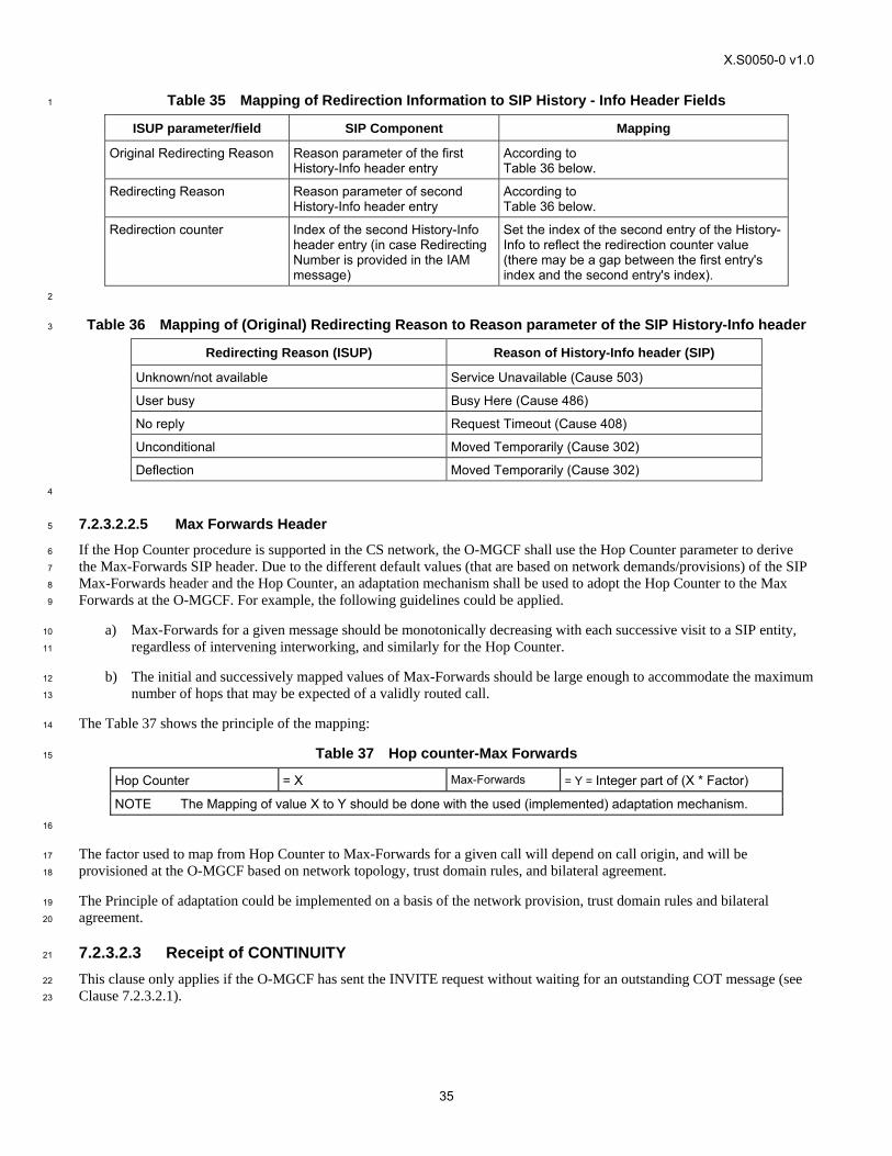
X.S0050-0 v1.0
35
Table 35 Mapping of Redirection Information to SIP History - Info Header Fields 1
ISUP parameter/field SIP Component Mapping
Original Redirecting Reason Reason parameter of the first History-Info header entry
According to Table 36 below.
Redirecting Reason Reason parameter of second History-Info header entry
According to Table 36 below.
Redirection counter Index of the second History-Info header entry (in case Redirecting Number is provided in the IAM message)
Set the index of the second entry of the History-Info to reflect the redirection counter value (there may be a gap between the first entry's index and the second entry's index).
2
Table 36 Mapping of (Original) Redirecting Reason to Reason parameter of the SIP History-Info header 3
Redirecting Reason (ISUP) Reason of History-Info header (SIP)
Unknown/not available Service Unavailable (Cause 503)
User busy Busy Here (Cause 486)
No reply Request Timeout (Cause 408)
Unconditional Moved Temporarily (Cause 302)
Deflection Moved Temporarily (Cause 302) 4
7.2.3.2.2.5 Max Forwards Header 5
If the Hop Counter procedure is supported in the CS network, the O-MGCF shall use the Hop Counter parameter to derive 6
the Max-Forwards SIP header. Due to the different default values (that are based on network demands/provisions) of the SIP 7
Max-Forwards header and the Hop Counter, an adaptation mechanism shall be used to adopt the Hop Counter to the Max 8
Forwards at the O-MGCF. For example, the following guidelines could be applied. 9
a) Max-Forwards for a given message should be monotonically decreasing with each successive visit to a SIP entity, 10
regardless of intervening interworking, and similarly for the Hop Counter. 11
b) The initial and successively mapped values of Max-Forwards should be large enough to accommodate the maximum 12
number of hops that may be expected of a validly routed call. 13
The Table 37 shows the principle of the mapping: 14
Table 37 Hop counter-Max Forwards 15
Hop Counter = X Max-Forwards = Y = Integer part of (X * Factor)
NOTE The Mapping of value X to Y should be done with the used (implemented) adaptation mechanism. 16
The factor used to map from Hop Counter to Max-Forwards for a given call will depend on call origin, and will be 17
provisioned at the O-MGCF based on network topology, trust domain rules, and bilateral agreement. 18
The Principle of adaptation could be implemented on a basis of the network provision, trust domain rules and bilateral 19
agreement. 20
7.2.3.2.3 Receipt of CONTINUITY 21
This clause only applies if the O-MGCF has sent the INVITE request without waiting for an outstanding COT message (see 22
Clause 7.2.3.2.1). 23
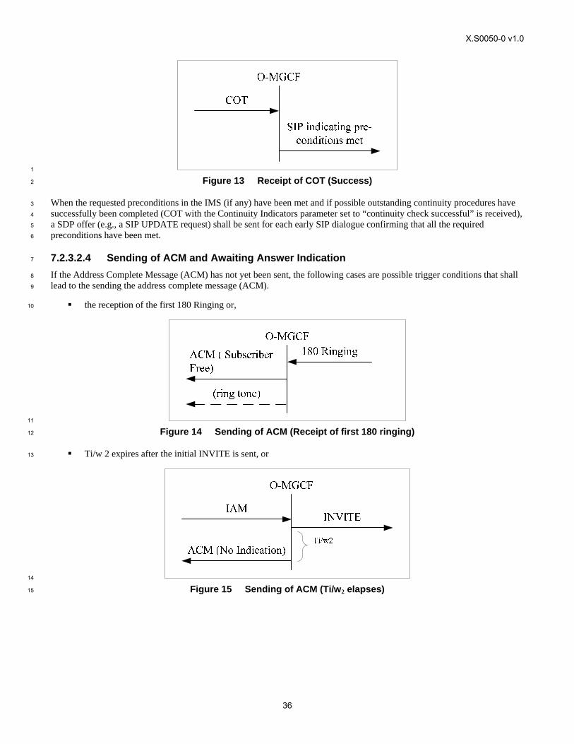
X.S0050-0 v1.0
36
1
Figure 13 Receipt of COT (Success) 2
When the requested preconditions in the IMS (if any) have been met and if possible outstanding continuity procedures have 3
successfully been completed (COT with the Continuity Indicators parameter set to “continuity check successful” is received), 4
a SDP offer (e.g., a SIP UPDATE request) shall be sent for each early SIP dialogue confirming that all the required 5
preconditions have been met. 6
7.2.3.2.4 Sending of ACM and Awaiting Answer Indication 7
If the Address Complete Message (ACM) has not yet been sent, the following cases are possible trigger conditions that shall 8
lead to the sending the address complete message (ACM). 9
the reception of the first 180 Ringing or, 10
11
Figure 14 Sending of ACM (Receipt of first 180 ringing) 12
Ti/w 2 expires after the initial INVITE is sent, or 13
14
Figure 15 Sending of ACM (Ti/w2 elapses) 15
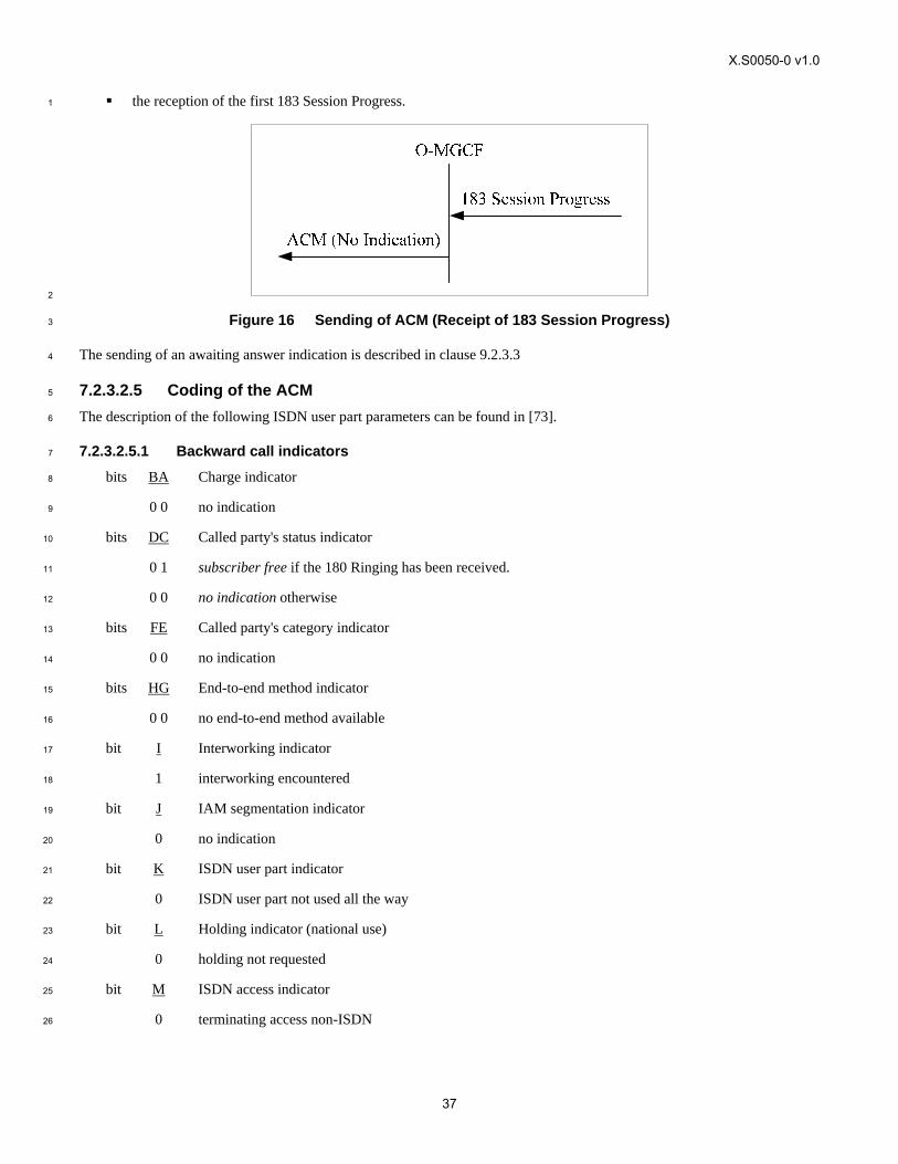
X.S0050-0 v1.0
37
the reception of the first 183 Session Progress. 1
2
Figure 16 Sending of ACM (Receipt of 183 Session Progress) 3
The sending of an awaiting answer indication is described in clause 9.2.3.3 4
7.2.3.2.5 Coding of the ACM 5
The description of the following ISDN user part parameters can be found in [73]. 6
7.2.3.2.5.1 Backward call indicators 7
bits BA Charge indicator 8
0 0 no indication 9
bits DC Called party's status indicator 10
0 1 subscriber free if the 180 Ringing has been received. 11
0 0 no indication otherwise 12
bits FE Called party's category indicator 13
0 0 no indication 14
bits HG End-to-end method indicator 15
0 0 no end-to-end method available 16
bit I Interworking indicator 17
1 interworking encountered 18
bit J IAM segmentation indicator 19
0 no indication 20
bit K ISDN user part indicator 21
0 ISDN user part not used all the way 22
bit L Holding indicator (national use) 23
0 holding not requested 24
bit M ISDN access indicator 25
0 terminating access non-ISDN 26
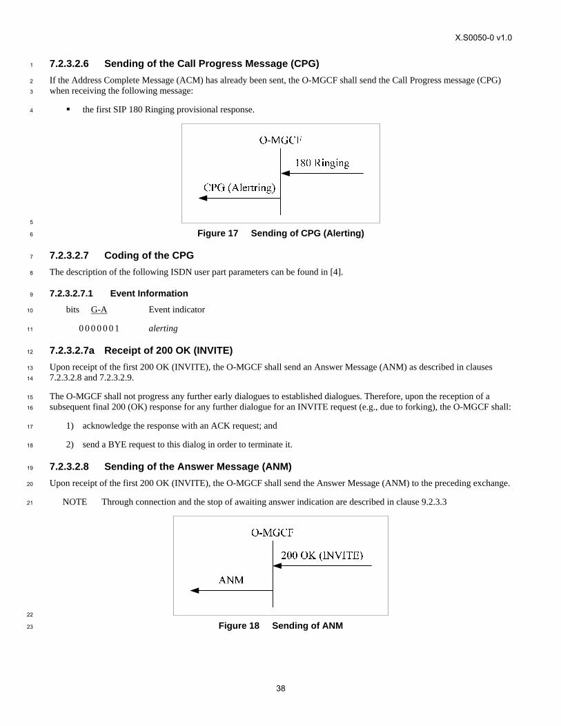
X.S0050-0 v1.0
38
7.2.3.2.6 Sending of the Call Progress Message (CPG) 1
If the Address Complete Message (ACM) has already been sent, the O-MGCF shall send the Call Progress message (CPG) 2
when receiving the following message: 3
the first SIP 180 Ringing provisional response. 4
5
Figure 17 Sending of CPG (Alerting) 6
7.2.3.2.7 Coding of the CPG 7
The description of the following ISDN user part parameters can be found in [4]. 8
7.2.3.2.7.1 Event Information 9
bits G-A Event indicator 10
0 0 0 0 0 0 1 alerting 11
7.2.3.2.7a Receipt of 200 OK (INVITE) 12
Upon receipt of the first 200 OK (INVITE), the O-MGCF shall send an Answer Message (ANM) as described in clauses 13
7.2.3.2.8 and 7.2.3.2.9. 14
The O-MGCF shall not progress any further early dialogues to established dialogues. Therefore, upon the reception of a 15
subsequent final 200 (OK) response for any further dialogue for an INVITE request (e.g., due to forking), the O-MGCF shall: 16
1) acknowledge the response with an ACK request; and 17
2) send a BYE request to this dialog in order to terminate it. 18
7.2.3.2.8 Sending of the Answer Message (ANM) 19
Upon receipt of the first 200 OK (INVITE), the O-MGCF shall send the Answer Message (ANM) to the preceding exchange. 20
NOTE Through connection and the stop of awaiting answer indication are described in clause 9.2.3.3 21
22
Figure 18 Sending of ANM 23
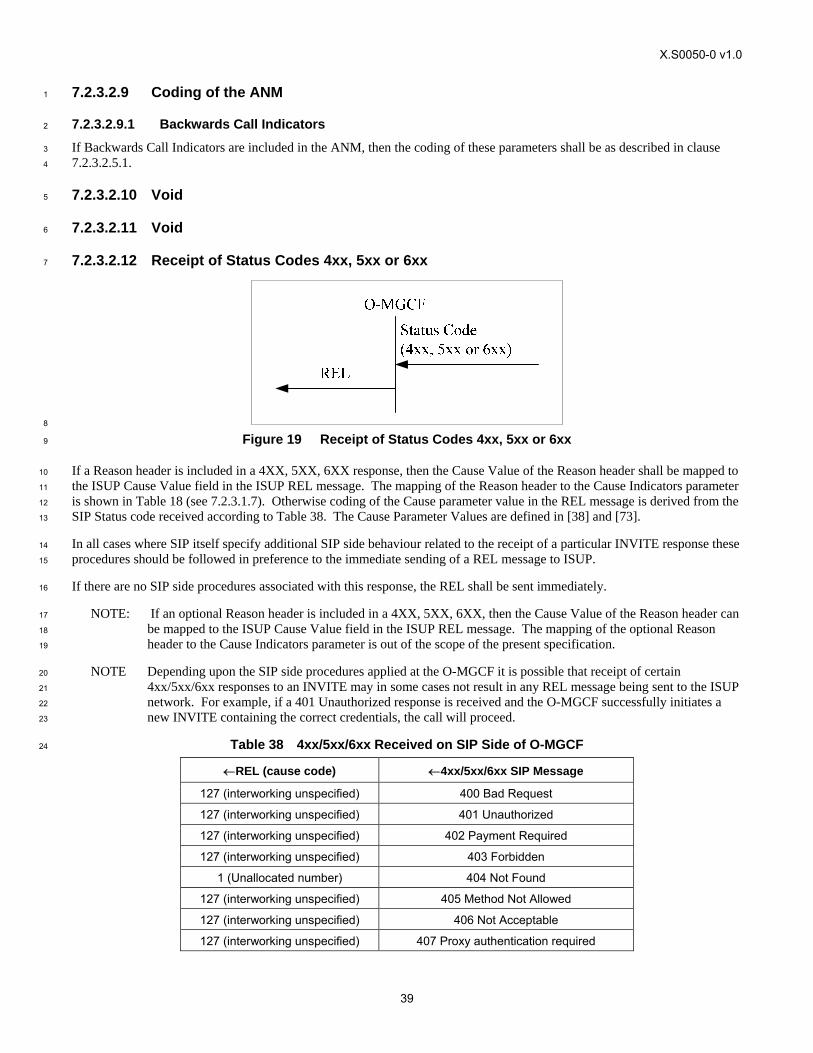
X.S0050-0 v1.0
39
7.2.3.2.9 Coding of the ANM 1
7.2.3.2.9.1 Backwards Call Indicators 2
If Backwards Call Indicators are included in the ANM, then the coding of these parameters shall be as described in clause 3
7.2.3.2.5.1. 4
7.2.3.2.10 Void 5
7.2.3.2.11 Void 6
7.2.3.2.12 Receipt of Status Codes 4xx, 5xx or 6xx 7
8
Figure 19 Receipt of Status Codes 4xx, 5xx or 6xx 9
If a Reason header is included in a 4XX, 5XX, 6XX response, then the Cause Value of the Reason header shall be mapped to 10
the ISUP Cause Value field in the ISUP REL message. The mapping of the Reason header to the Cause Indicators parameter 11
is shown in Table 18 (see 7.2.3.1.7). Otherwise coding of the Cause parameter value in the REL message is derived from the 12
SIP Status code received according to Table 38. The Cause Parameter Values are defined in [38] and [73]. 13
In all cases where SIP itself specify additional SIP side behaviour related to the receipt of a particular INVITE response these 14
procedures should be followed in preference to the immediate sending of a REL message to ISUP. 15
If there are no SIP side procedures associated with this response, the REL shall be sent immediately. 16
NOTE: If an optional Reason header is included in a 4XX, 5XX, 6XX, then the Cause Value of the Reason header can 17
be mapped to the ISUP Cause Value field in the ISUP REL message. The mapping of the optional Reason 18
header to the Cause Indicators parameter is out of the scope of the present specification. 19
NOTE Depending upon the SIP side procedures applied at the O-MGCF it is possible that receipt of certain 20
4xx/5xx/6xx responses to an INVITE may in some cases not result in any REL message being sent to the ISUP 21
network. For example, if a 401 Unauthorized response is received and the O-MGCF successfully initiates a 22
new INVITE containing the correct credentials, the call will proceed. 23
Table 38 4xx/5xx/6xx Received on SIP Side of O-MGCF 24
←REL (cause code) ←4xx/5xx/6xx SIP Message
127 (interworking unspecified) 400 Bad Request
127 (interworking unspecified) 401 Unauthorized
127 (interworking unspecified) 402 Payment Required
127 (interworking unspecified) 403 Forbidden
1 (Unallocated number) 404 Not Found
127 (interworking unspecified) 405 Method Not Allowed
127 (interworking unspecified) 406 Not Acceptable
127 (interworking unspecified) 407 Proxy authentication required
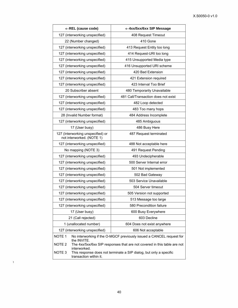
X.S0050-0 v1.0
40
←REL (cause code) ←4xx/5xx/6xx SIP Message
127 (interworking unspecified) 408 Request Timeout
22 (Number changed) 410 Gone
127 (interworking unspecified) 413 Request Entity too long
127 (interworking unspecified) 414 Request-URI too long
127 (interworking unspecified) 415 Unsupported Media type
127 (interworking unspecified) 416 Unsupported URI scheme
127 (interworking unspecified) 420 Bad Extension
127 (interworking unspecified) 421 Extension required
127 (interworking unspecified) 423 Interval Too Brief
20 Subscriber absent 480 Temporarily Unavailable
127 (interworking unspecified) 481 Call/Transaction does not exist
127 (interworking unspecified) 482 Loop detected
127 (interworking unspecified) 483 Too many hops
28 (Invalid Number format) 484 Address Incomplete
127 (interworking unspecified) 485 Ambiguous
17 (User busy) 486 Busy Here
127 (Interworking unspecified) or not interworked. (NOTE 1)
487 Request terminated
127 (interworking unspecified) 488 Not acceptable here
No mapping (NOTE 3) 491 Request Pending
127 (interworking unspecified) 493 Undecipherable
127 (interworking unspecified) 500 Server Internal error
127 (interworking unspecified) 501 Not implemented
127 (interworking unspecified) 502 Bad Gateway
127 (interworking unspecified) 503 Service Unavailable
127 (interworking unspecified) 504 Server timeout
127 (interworking unspecified) 505 Version not supported
127 (interworking unspecified) 513 Message too large
127 (interworking unspecified) 580 Precondition failure
17 (User busy) 600 Busy Everywhere
21 (Call rejected) 603 Decline
1 (unallocated number) 604 Does not exist anywhere
127 (interworking unspecified) 606 Not acceptable
NOTE 1 No interworking if the O-MGCF previously issued a CANCEL request for the INVITE.
NOTE 2 The 4xx/5xx/6xx SIP responses that are not covered in this table are not interworked.
NOTE 3 This response does not terminate a SIP dialog, but only a specific transaction within it.
1
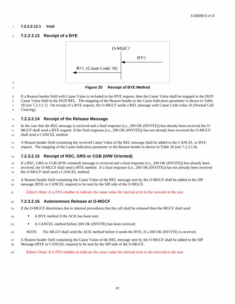
X.S0050-0 v1.0
41
7.2.3.2.12.1 Void 1
7.2.3 2.13 Receipt of a BYE 2
3
Figure 20 Receipt of BYE Method 4
If a Reason header field with Cause Value is included in the BYE request, then the Cause Value shall be mapped to the ISUP 5
Cause Value field in the ISUP REL. The mapping of the Reason header to the Cause Indicators parameter is shown in Table 6
18 (see 7.2.3.1.7). On receipt of a BYE request, the O-MGCF sends a REL message with Cause Code value 16 (Normal Call 7
Clearing). 8
7.2.3.2.14 Receipt of the Release Message 9
In the case that the REL message is received and a final response (i.e., 200 OK (INVITE)) has already been received the O-10
MGCF shall send a BYE request. If the final response (i.e., 200 OK (INVITE)) has not already been received the O-MGCF 11
shall send a CANCEL method. 12
A Reason header field containing the received Cause Value of the REL message shall be added to the CANCEL or BYE 13
request. The mapping of the Cause Indicators parameter to the Reason header is shown in Table 20 (see 7.2.3.1.8). 14
7.2.3.2.15 Receipt of RSC, GRS or CGB (H/W Oriented) 15
If a RSC, GRS or CGB (H/W oriented) message is received and a final response (i.e., 200 OK (INVITE)) has already been 16
received, the O-MGCF shall send a BYE method. If a final response (i.e., 200 OK (INVITE)) has not already been received 17
the O-MGCF shall send a CANCEL method. 18
A Reason header field containing the Cause Value of the REL message sent by the O-MGCF shall be added to the SIP 19
message (BYE or CANCEL request) to be sent by the SIP side of the O-MGCF. 20
Editor's Note: It is FFS whether to indicate the cause value for internal error in the network to the user. 21
7.2.3.2.16 Autonomous Release at O-MGCF 22
If the O-MGCF determines due to internal procedures that the call shall be released then the MGCF shall send 23
A BYE method if the ACK has been sent. 24
A CANCEL method before 200 OK (INVITE) has been received. 25
NOTE: The MGCF shall send the ACK method before it sends the BYE, if a 200 OK (INVITE) is received. 26
A Reason header field containing the Cause Value of the REL message sent by the O-MGCF shall be added to the SIP 27
Message (BYE or CANCEL request) to be sent by the SIP side of the O-MGCF. 28
Editor's Note: It is FFS whether to indicate the cause value for internal error in the network to the user. 29
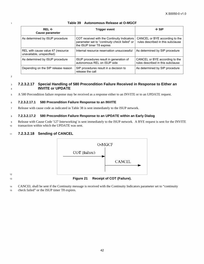
X.S0050-0 v1.0
42
Table 39 Autonomous Release at O-MGCF 1
REL Cause parameter
Trigger event SIP
As determined by ISUP procedure COT received with the Continuity Indicators parameter set to “continuity check failed” or the ISUP timer T8 expires
CANCEL or BYE according to the rules described in this subclause
REL with cause value 47 (resource unavailable, unspecified)
Internal resource reservation unsuccessful As determined by SIP procedure
As determined by ISUP procedure ISUP procedures result in generation of autonomous REL on ISUP side
CANCEL or BYE according to the rules described in this subclause
Depending on the SIP release reason SIP procedures result in a decision to release the call
As determined by SIP procedure
2
7.2.3.2.17 Special Handling of 580 Precondition Failure Received in Response to Either an 3
INVITE or UPDATE 4
A 580 Precondition failure response may be received as a response either to an INVITE or to an UPDATE request. 5
7.2.3.2.17.1 580 Precondition Failure Response to an INVITE 6
Release with cause code as indicated in Table 38 is sent immediately to the ISUP network. 7
7.2.3.2.17.2 580 Precondition Failure Response to an UPDATE within an Early Dialog 8
Release with Cause Code '127 Interworking' is sent immediately to the ISUP network. A BYE request is sent for the INVITE 9
transaction within which the UPDATE was sent. 10
7.2.3.2.18 Sending of CANCEL 11
12
Figure 21 Receipt of COT (Failure). 13
CANCEL shall be sent if the Continuity message is received with the Continuity Indicators parameter set to “continuity 14
check failed” or the ISUP timer T8 expires. 15
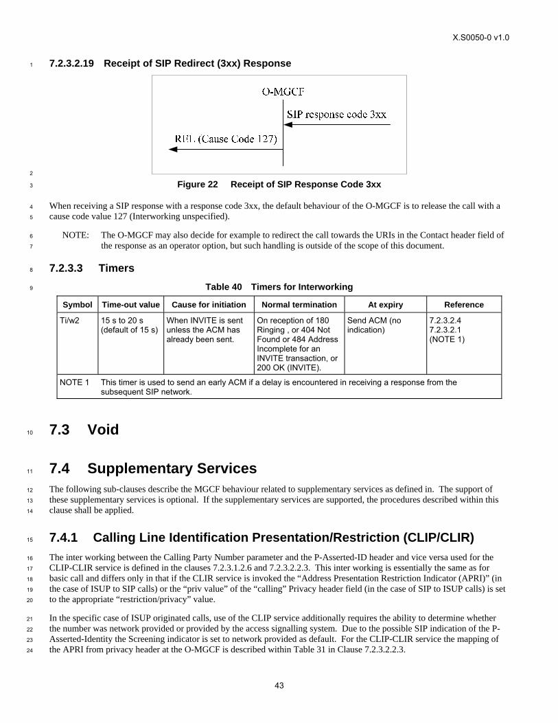
X.S0050-0 v1.0
43
7.2.3.2.19 Receipt of SIP Redirect (3xx) Response 1
2
Figure 22 Receipt of SIP Response Code 3xx 3
When receiving a SIP response with a response code 3xx, the default behaviour of the O-MGCF is to release the call with a 4
cause code value 127 (Interworking unspecified). 5
NOTE: The O-MGCF may also decide for example to redirect the call towards the URIs in the Contact header field of 6
the response as an operator option, but such handling is outside of the scope of this document. 7
7.2.3.3 Timers 8
Table 40 Timers for Interworking 9
Symbol Time-out value Cause for initiation Normal termination At expiry Reference
Ti/w2 15 s to 20 s (default of 15 s)
When INVITE is sent unless the ACM has already been sent.
On reception of 180 Ringing , or 404 Not Found or 484 Address Incomplete for an INVITE transaction, or 200 OK (INVITE).
Send ACM (no indication)
7.2.3.2.4 7.2.3.2.1 (NOTE 1)
NOTE 1 This timer is used to send an early ACM if a delay is encountered in receiving a response from the subsequent SIP network.
7.3 Void 10
7.4 Supplementary Services 11
The following sub-clauses describe the MGCF behaviour related to supplementary services as defined in. The support of 12
these supplementary services is optional. If the supplementary services are supported, the procedures described within this 13
clause shall be applied. 14
7.4.1 Calling Line Identification Presentation/Restriction (CLIP/CLIR) 15
The inter working between the Calling Party Number parameter and the P-Asserted-ID header and vice versa used for the 16
CLIP-CLIR service is defined in the clauses 7.2.3.1.2.6 and 7.2.3.2.2.3. This inter working is essentially the same as for 17
basic call and differs only in that if the CLIR service is invoked the “Address Presentation Restriction Indicator (APRI)” (in 18
the case of ISUP to SIP calls) or the “priv value” of the “calling” Privacy header field (in the case of SIP to ISUP calls) is set 19
to the appropriate “restriction/privacy” value. 20
In the specific case of ISUP originated calls, use of the CLIP service additionally requires the ability to determine whether 21
the number was network provided or provided by the access signalling system. Due to the possible SIP indication of the P-22
Asserted-Identity the Screening indicator is set to network provided as default. For the CLIP-CLIR service the mapping of 23
the APRI from privacy header at the O-MGCF is described within Table 31 in Clause 7.2.3.2.2.3. 24
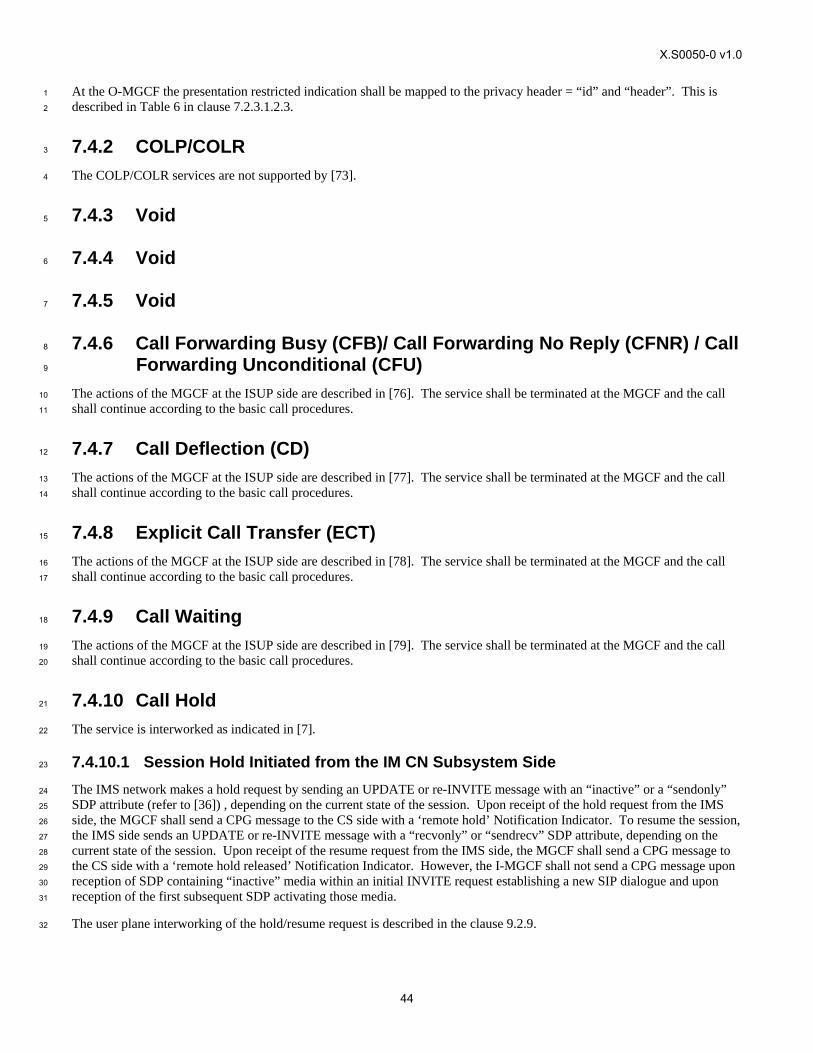
X.S0050-0 v1.0
44
At the O-MGCF the presentation restricted indication shall be mapped to the privacy header = “id” and “header”. This is 1
described in Table 6 in clause 7.2.3.1.2.3. 2
7.4.2 COLP/COLR 3
The COLP/COLR services are not supported by [73]. 4
7.4.3 Void 5
7.4.4 Void 6
7.4.5 Void 7
7.4.6 Call Forwarding Busy (CFB)/ Call Forwarding No Reply (CFNR) / Call 8
Forwarding Unconditional (CFU) 9
The actions of the MGCF at the ISUP side are described in [76]. The service shall be terminated at the MGCF and the call 10
shall continue according to the basic call procedures. 11
7.4.7 Call Deflection (CD) 12
The actions of the MGCF at the ISUP side are described in [77]. The service shall be terminated at the MGCF and the call 13
shall continue according to the basic call procedures. 14
7.4.8 Explicit Call Transfer (ECT) 15
The actions of the MGCF at the ISUP side are described in [78]. The service shall be terminated at the MGCF and the call 16
shall continue according to the basic call procedures. 17
7.4.9 Call Waiting 18
The actions of the MGCF at the ISUP side are described in [79]. The service shall be terminated at the MGCF and the call 19
shall continue according to the basic call procedures. 20
7.4.10 Call Hold 21
The service is interworked as indicated in [7]. 22
7.4.10.1 Session Hold Initiated from the IM CN Subsystem Side 23
The IMS network makes a hold request by sending an UPDATE or re-INVITE message with an “inactive” or a “sendonly” 24
SDP attribute (refer to [36]) , depending on the current state of the session. Upon receipt of the hold request from the IMS 25
side, the MGCF shall send a CPG message to the CS side with a ‘remote hold’ Notification Indicator. To resume the session, 26
the IMS side sends an UPDATE or re-INVITE message with a “recvonly” or “sendrecv” SDP attribute, depending on the 27
current state of the session. Upon receipt of the resume request from the IMS side, the MGCF shall send a CPG message to 28
the CS side with a ‘remote hold released’ Notification Indicator. However, the I-MGCF shall not send a CPG message upon 29
reception of SDP containing “inactive” media within an initial INVITE request establishing a new SIP dialogue and upon 30
reception of the first subsequent SDP activating those media. 31
The user plane interworking of the hold/resume request is described in the clause 9.2.9. 32
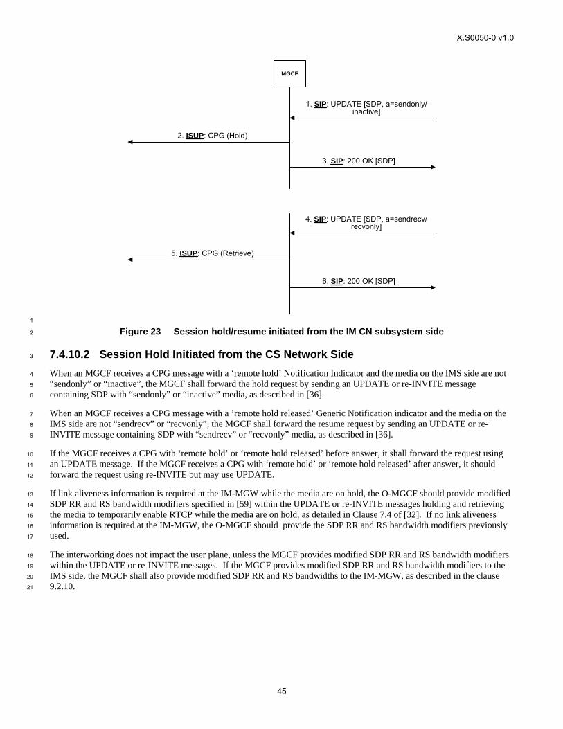
X.S0050-0 v1.0
45
MGCF
2. ISUP: CPG (Hold)
3. SIP: 200 OK [SDP]
1. SIP: UPDATE [SDP, a=sendonly/inactive]
4. SIP: UPDATE [SDP, a=sendrecv/recvonly]
5. ISUP: CPG (Retrieve)
6. SIP: 200 OK [SDP]
1
Figure 23 Session hold/resume initiated from the IM CN subsystem side 2
7.4.10.2 Session Hold Initiated from the CS Network Side 3
When an MGCF receives a CPG message with a ‘remote hold’ Notification Indicator and the media on the IMS side are not 4
“sendonly” or “inactive”, the MGCF shall forward the hold request by sending an UPDATE or re-INVITE message 5
containing SDP with “sendonly” or “inactive” media, as described in [36]. 6
When an MGCF receives a CPG message with a ’remote hold released’ Generic Notification indicator and the media on the 7
IMS side are not “sendrecv” or “recvonly”, the MGCF shall forward the resume request by sending an UPDATE or re-8
INVITE message containing SDP with “sendrecv” or “recvonly” media, as described in [36]. 9
If the MGCF receives a CPG with ‘remote hold’ or ‘remote hold released’ before answer, it shall forward the request using 10
an UPDATE message. If the MGCF receives a CPG with ‘remote hold’ or ‘remote hold released’ after answer, it should 11
forward the request using re-INVITE but may use UPDATE. 12
If link aliveness information is required at the IM-MGW while the media are on hold, the O-MGCF should provide modified 13
SDP RR and RS bandwidth modifiers specified in [59] within the UPDATE or re-INVITE messages holding and retrieving 14
the media to temporarily enable RTCP while the media are on hold, as detailed in Clause 7.4 of [32]. If no link aliveness 15
information is required at the IM-MGW, the O-MGCF should provide the SDP RR and RS bandwidth modifiers previously 16
used. 17
The interworking does not impact the user plane, unless the MGCF provides modified SDP RR and RS bandwidth modifiers 18
within the UPDATE or re-INVITE messages. If the MGCF provides modified SDP RR and RS bandwidth modifiers to the 19
IMS side, the MGCF shall also provide modified SDP RR and RS bandwidths to the IM-MGW, as described in the clause 20
9.2.10. 21
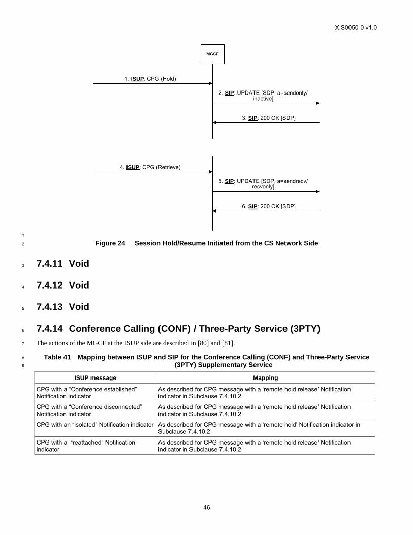
X.S0050-0 v1.0
46
MGCF
1. ISUP: CPG (Hold)
3. SIP: 200 OK [SDP]
2. SIP: UPDATE [SDP, a=sendonly/inactive]
5. SIP: UPDATE [SDP, a=sendrecv/recvonly]
4. ISUP: CPG (Retrieve)
6. SIP: 200 OK [SDP]
1
Figure 24 Session Hold/Resume Initiated from the CS Network Side 2
7.4.11 Void 3
7.4.12 Void 4
7.4.13 Void 5
7.4.14 Conference Calling (CONF) / Three-Party Service (3PTY) 6
The actions of the MGCF at the ISUP side are described in [80] and [81]. 7
Table 41 Mapping between ISUP and SIP for the Conference Calling (CONF) and Three-Party Service 8
(3PTY) Supplementary Service 9
ISUP message Mapping
CPG with a “Conference established” Notification indicator
As described for CPG message with a ‘remote hold release’ Notification indicator in Subclause 7.4.10.2
CPG with a “Conference disconnected” Notification indicator
As described for CPG message with a ‘remote hold release’ Notification indicator in Subclause 7.4.10.2
CPG with an “isolated” Notification indicator As described for CPG message with a ‘remote hold’ Notification indicator in Subclause 7.4.10.2
CPG with a “reattached” Notification indicator
As described for CPG message with a ‘remote hold release’ Notification indicator in Subclause 7.4.10.2
X.S0050-0 v1.0
47
7.4.15 Void 1
7.4.16 Void 2
7.4.17 Multi-Level Precedence and Pre-emption (MLPP) 3
The actions of the MGCF at the ISUP side are described in [82] and [83]. The service shall be terminated at the MGCF and 4
the call shall continue according to the basic call procedures. 5
7.4.18 Void 6
7.4.19 Void 7
7.4.20 Void 8
7.4.21 User-to-User Signalling (UUS) 9
The actions of the MGCF at the ISUP side are described in [84]. The service shall be terminated at the MGCF and the call 10
shall continue according to the basic call procedures. 11
7.4.22 Void 12
7.4.23 Void 13
7.5 Void 14
8 User Plane Interworking 15
8.1 Void 16
8.2 Interworking between IM CN Subsystem and TDM-based CS 17
Network 18
It shall be possible for the IM CN subsystem to interwork with the TDM based CS networks (e.g., PSTN, ISDN). Figure 25 19
describes the user plane protocol stack to provide the particular interworking. 20
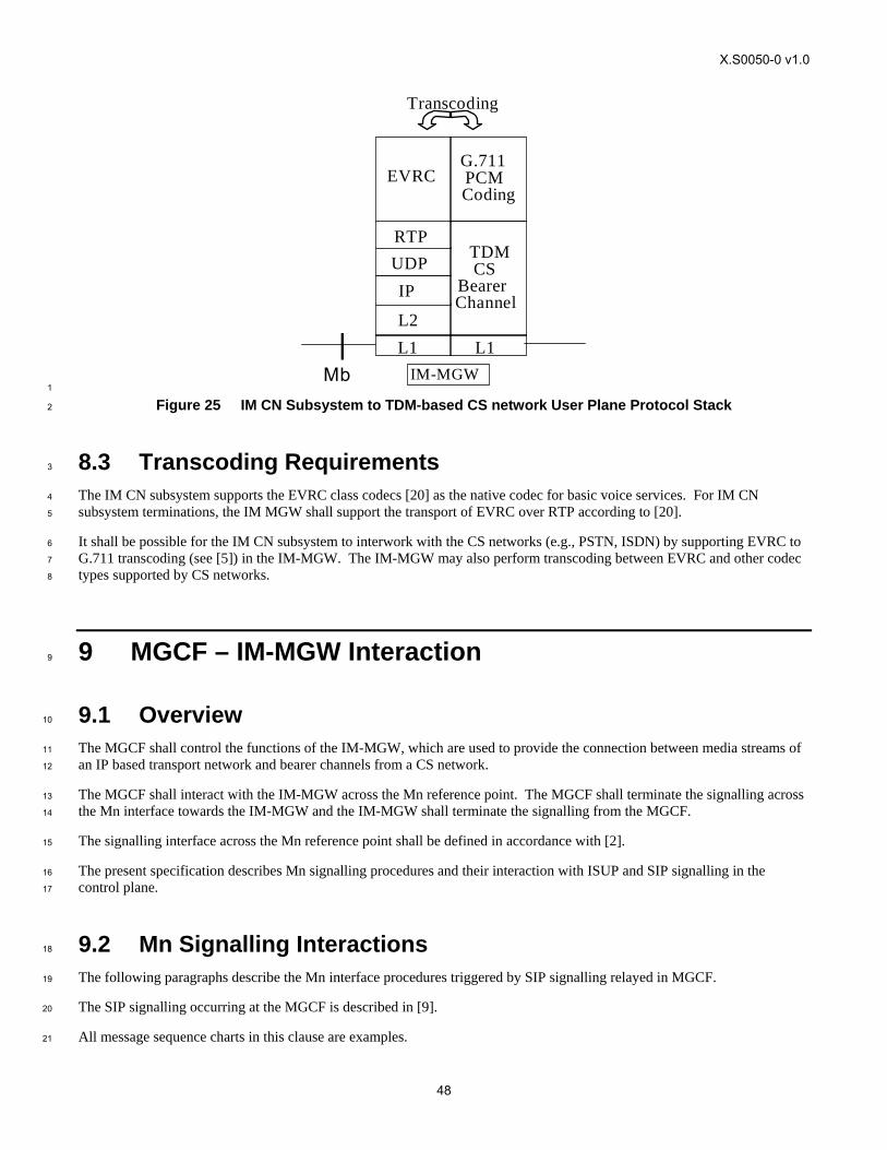
X.S0050-0 v1.0
48
EVRC
IM-MGWL1 L2
IP UDP RTP
G.711 PCM Coding
L1
TDM CS
Bearer Channel
Transcoding
Mb 1
Figure 25 IM CN Subsystem to TDM-based CS network User Plane Protocol Stack 2
8.3 Transcoding Requirements 3
The IM CN subsystem supports the EVRC class codecs [20] as the native codec for basic voice services. For IM CN 4
subsystem terminations, the IM MGW shall support the transport of EVRC over RTP according to [20]. 5
It shall be possible for the IM CN subsystem to interwork with the CS networks (e.g., PSTN, ISDN) by supporting EVRC to 6
G.711 transcoding (see [5]) in the IM-MGW. The IM-MGW may also perform transcoding between EVRC and other codec 7
types supported by CS networks. 8
9 MGCF – IM-MGW Interaction 9
9.1 Overview 10
The MGCF shall control the functions of the IM-MGW, which are used to provide the connection between media streams of 11
an IP based transport network and bearer channels from a CS network. 12
The MGCF shall interact with the IM-MGW across the Mn reference point. The MGCF shall terminate the signalling across 13
the Mn interface towards the IM-MGW and the IM-MGW shall terminate the signalling from the MGCF. 14
The signalling interface across the Mn reference point shall be defined in accordance with [2]. 15
The present specification describes Mn signalling procedures and their interaction with ISUP and SIP signalling in the 16
control plane. 17
9.2 Mn Signalling Interactions 18
The following paragraphs describe the Mn interface procedures triggered by SIP signalling relayed in MGCF. 19
The SIP signalling occurring at the MGCF is described in [9]. 20
All message sequence charts in this clause are examples. 21
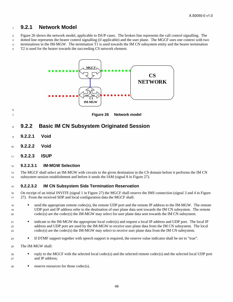
X.S0050-0 v1.0
49
9.2.1 Network Model 1
Figure 26 shows the network model, applicable to ISUP cases. The broken line represents the call control signalling. The 2
dotted line represents the bearer control signalling (if applicable) and the user plane. The MGCF uses one context with two 3
terminations in the IM-MGW. The termination T1 is used towards the IM CN subsystem entity and the bearer termination 4
T2 is used for the bearer towards the succeeding CS network element. 5
IM-MGW
MGCF
C1 T1 T2
CS NETWORK
6
Figure 26 Network model 7
9.2.2 Basic IM CN Subsystem Originated Session 8
9.2.2.1 Void 9
9.2.2.2 Void 10
9.2.2.3 ISUP 11
9.2.2.3.1 IM-MGW Selection 12
The MGCF shall select an IM-MGW with circuits to the given destination in the CS domain before it performs the IM CN 13
subsystem session establishment and before it sends the IAM (signal 8 in Figure 27). 14
9.2.2.3.2 IM CN Subsystem Side Termination Reservation 15
On receipt of an initial INVITE (signal 1 in Figure 27) the MGCF shall reserve the IMS connection (signal 3 and 4 in Figure 16
27). From the received SDP and local configuration data the MGCF shall: 17
send the appropriate remote codec(s), the remote UDP port and the remote IP address to the IM-MGW. The remote 18
UDP port and IP address refer to the destination of user plane data sent towards the IM CN subsystem. The remote 19
codec(s) are the codec(s) the IM-MGW may select for user plane data sent towards the IM CN subsystem. 20
indicate to the IM-MGW the appropriate local codec(s) and request a local IP address and UDP port. The local IP 21
address and UDP port are used by the IM-MGW to receive user plane data from the IM CN subsystem. The local 22
codec(s) are the codec(s) the IM-MGW may select to receive user plane data from the IM CN subsystem. 23
If DTMF support together with speech support is required, the reserve value indicator shall be set to “true”. 24
The IM-MGW shall: 25
reply to the MGCF with the selected local codec(s) and the selected remote codec(s) and the selected local UDP port 26
and IP address; 27
reserve resources for those codec(s). 28
X.S0050-0 v1.0
50
The MCGF shall send selected local codec(s) and the selected remote codec and the selected local UDP port and IP address 1
to the IMS in the Session Progress (signal 5 in Figure 27). 2
9.2.2.3.3 IM CN Subsystem Side Session Establishment 3
Dependent on what the MGCF receives in the PRACK message (signal 9 in Figure 27) the MGCF may change the IMS 4
resources. If no SDP is received, or if the received SDP does not contain relevant changes compared to the previous SDP, 5
the no action is taken. Otherwise the MGCF provides (c.f. signal 10) the IM-MGW: 6
the appropriate remote codec(s), the remote UDP port and the remote IP address; 7
optionally the appropriate local codec(s), UDP port and IP address; 8
If DTMF support together with speech support is required, the reserve value indicator shall be set to “true”. 9
The IM-MGW shall: 10
reply to the MGCF with the selected remote codec; 11
reply to the MGCF with the selected local codec(s), if the MGCF supplied local codec(s); 12
update the codec reservation and remote IP address and UDP port in accordance with the received information. 13
The MGCF shall include the selected codec(s) UDP port and IP address in 200 OK (PRACK) (signal 12 in Figure 27) sent 14
back to the IMS. 15
9.2.2.3.4 CS Network Side Circuit Reservation 16
The MGCF shall request the IM-MGW to reserve a circuit. The MGCF sends the IAM to the succeeding node including the 17
reserved circuit identity. 18
9.2.2.3.5 Through-Connection 19
During the reservation of the TDM Circuit and the IMS Connection Point procedures, the MGCF shall either request the IM-20
MGW to backward through-connect the termination, or the MGCF shall both-way through-connect the TDM termination 21
already on this stage (signal 6 in Figure 27). During the reservation of the IMS connection, the MGCF shall request the IM-22
MGW to backward through-connect the IMS termination (signal 3 in Figure 27). 23
When the MGCF receives the ISUP:ANM answer indication, it shall request the IM-MGW to both-way through-connect the 24
terminations (signal 21 in Figure 27), unless those terminations are already both-way through-connected. 25
9.2.2.3.6 Continuity Check 26
The MGCF may request a continuity check on the connection towards the CS network within the IAM message. In this case, 27
the MGCF shall request the IM-MGW to generate a continuity check tone on the TDM termination. The IM-MGW shall 28
then notify the MGCF of an incoming continuity check tone on the corresponding circuit. In addition to other conditions 29
detailed in Section 7, the MGCF shall wait until receiving this notification before sending the COT. (Not depicted in Figure 30
27) 31
9.2.2.3.7 Codec Handling 32
The IM-MGW may include a speech transcoder based upon the speech coding information provided to each termination. 33
9.2.2.3.8 Voice Processing Function 34
A voice processing function located on the IM-MGW may be used to achieve desired acoustic quality on the terminations. If 35
the voice processing function is used, the MGCF shall request the activation of it in the termination towards the CS network 36
(signal 23 in Figure 27). 37
X.S0050-0 v1.0
51
9.2.2.3.9 Failure Handling in MGCF 1
If any procedure between the MGCF and the IM-MGW is not completed successfully session shall be released as described 2
in clause 9.2.6. 3
9.2.2.3.10 Message Sequence Chart 4
Figure 27 shows the message sequence chart for the IM CN subsystem originating session. In the chart the MGCF requests 5
the seizure of an IM CN subsystem side termination and a CS network side bearer termination. When the MGCF receives an 6
answer indication, it requests the IM-MGW to both-way through-connect the terminations. The MGCF requests the possible 7
activation of the voice processing functions for the bearer terminations. Dashed lines represent optional or conditional 8
messages. 9
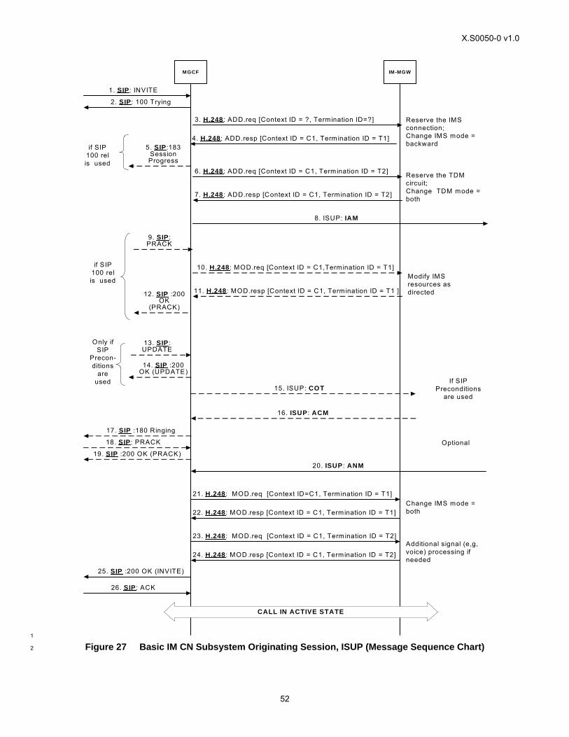
X.S0050-0 v1.0
52
MGCF IM-MGW
1. SIP : INVITE
2. SIP: 100 Trying
8. ISUP: IAM
6. H.248 : ADD.req [Context ID = C1, Termination ID = T2]
7. H.248 : ADD.resp [Context ID = C1, Termination ID = T2]
3. H.248 : ADD.req [Context ID = ?, Termination ID=?]
4. H.248: ADD.resp [Context ID = C1, Termination ID = T1]5. SIP :183
Session Progress
9. SIP : PRACK
12. SIP :200 OK
(PRACK)
10. H.248 : MOD.req [Context ID = C1,Termination ID = T1]
11. H.248 : MOD.resp [Context ID = C1, Termination ID = T1 ]
13. SIP : UPDATE
14. SIP :200 OK (UPDATE)
15. ISUP: COT
16. ISUP : ACM
17. SIP :180 Ringing
21. H.248 : MOD.req [Context ID=C1, Termination ID = T1]
22. H.248 : MOD.resp [Context ID = C1, Termination ID = T1]
20. ISUP : ANM
18. SIP : PRACK
19. SIP :200 OK (PRACK)
25. SIP :200 OK (INVITE)
26. SIP : ACK
CALL IN ACTIVE STATE
23. H.248 : MOD.req [Context ID = C1, Termination ID = T2]
24. H.248 : MOD.resp [Context ID = C1, Termination ID = T2]
Reserve the IMSconnection;Change IMS mode = backward
Modify IMS resources as directed
Reserve the TDM circuit;Change TDM mode = both
Change IMS mode = both
Additional signal (e,g, voice) processing if needed
Only if SIP
Precon-ditions
are used If SIP
Preconditions are used
Optional
if SIP 100 rel is used
if SIP 100 rel is used
1
Figure 27 Basic IM CN Subsystem Originating Session, ISUP (Message Sequence Chart) 2
X.S0050-0 v1.0
53
9.2.3 Basic CS Network Originated Session 1
9.2.3.1 Void 2
9.2.3.2 Void 3
9.2.3.3 ISUP 4
9.2.3.3.1 IM-MGW Selection 5
The MGCF selects the IM-MGW based on the received circuit identity in the IAM. 6
9.2.3.3.2 CS Network Side Circuit Reservation 7
The MGCF shall request the IM-MGW to reserve a circuit. 8
9.2.3.3.3 IM CN Subsystem Side Termination Reservation 9
The MGCF shall derive from configuration data one or several appropriate local codec(s) the IM-MGW may use to receive 10
user plane data from the IM CN subsystem. At this time (c.f. signals 2 and 3 in Figure 28), the MGCF shall indicate the local 11
codec(s) and request a local IP address and UDP port from the IM-MGW. The local IP address and UDP port are used by the 12
IM-MGW to receive user plane data from the IM CN subsystem. If DTMF support together with speech support is required, 13
or if the resources for multiple speech codecs shall be reserved at this stage, the reserve value indicator shall be set to “true”. 14
The IM-MGW shall reply to the MGCF with the selected local codec(s) and the selected local IP address and UDP port. 15
The MGCF shall send this information in the INVITE (signal 6 in Figure 28) to the IM CN subsystem. 16
9.2.3.3.4 IM CN Subsystem Side Session Establishment 17
The MGCF shall provide configuration data (derived from SDP received in signal 8 in Figure 28 and local configuration 18
data) using signals 9 and 10 or 22a and 22b in Figure 28, as detailed below: 19
The MGCF shall indicate the remote IP address and UDP port, i.e., the destination IP address and UDP port for data 20
sent in the user plane towards the IM CN subsystem. 21
The MGCF shall indicate the remote codec(s), i.e., the speech codec(s) for data sent in the user plane towards the IM 22
CN subsystem. 23
– The MGCF may indicate the local codec(s) and the local IP address and UDP port. The MGCF shall indicate 24
the local codec(s) if a change is required. 25
– If DTMF support together with speech support is required, the reserve value indicator shall be set to “true”. 26
The IM-MGW shall reply with the selected remote codec(s) and reserve resources for these codec(s). If local codec(s) were 27
received, the IM-MGW shall also reply with the selected local codec(s) and reserve the corresponding resources. 28
If the selected local codec(s) differ from the codec(s) received in the SDP of signal 8 in Figure 28 (if any), the MGCF shall 29
send the reserved speech codec(s), and the local IP address and UDP port in the PRACK (signal 11 in Figure 28) to the IMS. 30
If the selected local codec(s) differ from the codec(s) received in the SDP of signal 22 in Figure 28 (if any), the MGCF shall 31
send the local reserved codec(s), and the local IP address and UDP port in an re-INVITE or UPDATE (not depicted in Figure 32
28) to the IMS. 33
9.2.3.3.5 Called Party Alerting 34
The MGCF shall request the IM-MGW to provide an awaiting answer indication (ringing tone) to the calling party (signals 35
19 and 20 in Figure 28) , when the first of the following conditions is satisfied: 36
the MGCF receives the first 180 Ringing message; 37
X.S0050-0 v1.0
54
Timer T i/w2 expires. 1
9.2.3.3.6 Called Party Answer 2
When the MGCF receives a 200 OK message (signal 22 in Figure 28), it shall request the IM-MGW to stop providing the 3
ringing tone to the calling party (signals 23 and 24 in Figure 28). 4
9.2.3.3.7 Through-Connection 5
The MGCF shall either request the IM-MGW to backward through-connect the TDM termination, or the MGCF shall both-6
way through-connect the TDM termination already on this stage (signals 2 and 3 in Figure 28). The MGCF shall request the 7
IM-MGW to backward through-connect the IMS termination (signals 4 and 5 in Figure 28). 8
When the MGCF receives the SIP 200 OK(INVITE) message, it shall request the IM-MGW to both-way through-connect the 9
terminations (signals 25 and 26 in Figure 28), unless those terminations are already both-way through-connected. 10
9.2.3.3.8 Continuity Check 11
If a continuity check on the connection towards the CS network is requested in the IAM message, the MGCF shall request 12
loop-back of a received continuity check tone on the TDM circuit. Upon reception of the COT message, the MGCF shall 13
request the removal of the loop-back. (Not depicted in Figure 28) 14
9.2.3.3.9 Codec Handling 15
The IM-MGW may include a speech transcoder based upon the speech coding information provided to each termination. 16
9.2.3.3.10 Voice Processing Function 17
A voice processing function located on the IM-MGW may be used to achieve desired acoustic quality on the terminations. If 18
the voice processing function is used, the MGCF shall request the activation of it in the termination towards the CS network 19
(signal 23 in Figure 28). 20
9.2.3.3.11 Failure Handling in MGCF 21
If any procedure between the MGCF and the IM-MGW is not completed successfully, the session shall be released as 22
described in clause 9.2.6. 23
9.2.3.3.12 Message Sequence Chart 24
Figure 28 shows the message sequence chart for the CS network originating Session with ISUP. In the chart the MGCF 25
requests seizure of the IM CN subsystem side termination and CS network side bearer termination. When the MGCF 26
receives an answer indication, it requests the IM-MGW to both-way through-connect the terminations. The MGCF may 27
request the possible activation of the voice processing functions for the terminations. Dashed lines represent optional or 28
conditional messages. 29
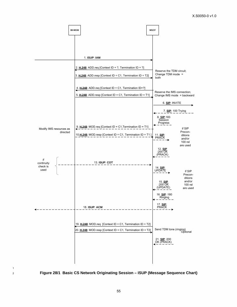
X.S0050-0 v1.0
55
IM-MGW MGCF
6. SIP: INVITE
7. SIP: 100 Trying
1. ISUP: IAM
2. H.248: ADD.req [Context ID = ?, Termination ID = ?]
3. H.248: ADD.resp [Context ID = C1, Termination ID = T2]
4. H.248: ADD.req [Context ID = C1, Termination ID=?]
5. H.248: ADD.resp [Context ID = C1, Termination ID = T1]
8. SIP:183 Session Progress
11. SIP: PRACK
12. SIP :200 OK (PRACK)
9. H.248: MOD.req [Context ID = C1,Termination ID = T1]
10.H.248: MOD.resp [Context ID = C1, Termination ID = T1 ]
14. SIP: UPDATE
15. SIP :200 OK
(UPDATE)
13. ISUP: COT
16. SIP :180 Ringing
17. SIP: PRACK
21. SIP :200 OK (PRACK)
19. H.248: MOD.req [Context ID = C1, Termination ID = T2]
20. H.248: MOD.resp [Context ID = C1, Termination ID = T2]
18. ISUP: ACM
Reserve the TDM circuit;Change TDM mode = both
Reserve the IMS connection; Change IMS mode = backward
Modify IMS resources as directed
Send TDM tone (ringing)
if SIP Precon-ditions and/or 100 rel
are used
if SIP Precon-ditions and/or 100 rel
are used
Optional
if continuity check is
used
1
Figure 28/1 Basic CS Network Originating Session – ISUP (Message Sequence Chart) 2
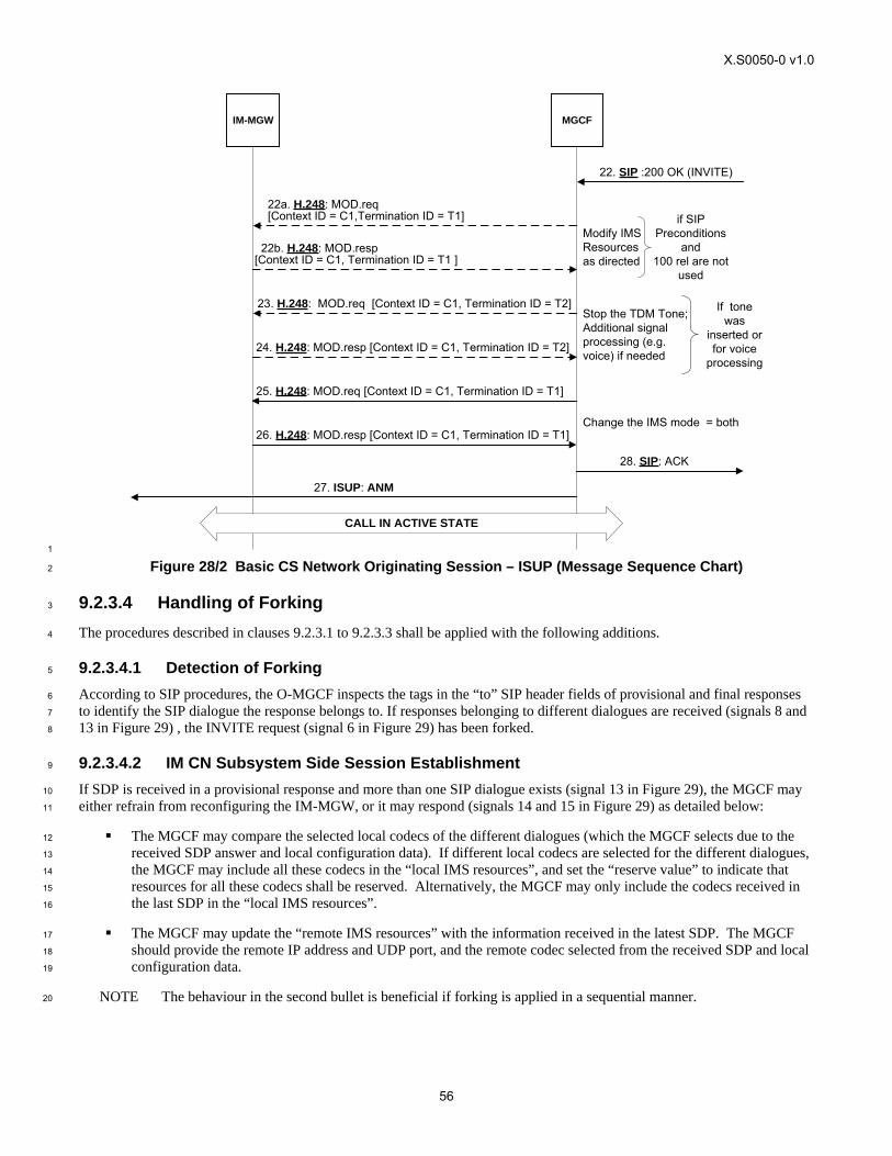
X.S0050-0 v1.0
56
IM-MGW MGCF
23. H.248: MOD.req [Context ID = C1, Termination ID = T2]
24. H.248: MOD.resp [Context ID = C1, Termination ID = T2]
28. SIP: ACK
25. H.248: MOD.req [Context ID = C1, Termination ID = T1]
26. H.248: MOD.resp [Context ID = C1, Termination ID = T1]
27. ISUP: ANM
22. SIP :200 OK (INVITE)
CALL IN ACTIVE STATE
Stop the TDM Tone;Additional signal processing (e.g. voice) if needed
Change the IMS mode = both
22a. H.248: MOD.req [Context ID = C1,Termination ID = T1]
22b. H.248: MOD.resp[Context ID = C1, Termination ID = T1 ]
if SIP Preconditions
and100 rel are not
used
If tone
was inserted or for voice
processing
Modify IMS Resources as directed
1
Figure 28/2 Basic CS Network Originating Session – ISUP (Message Sequence Chart) 2
9.2.3.4 Handling of Forking 3
The procedures described in clauses 9.2.3.1 to 9.2.3.3 shall be applied with the following additions. 4
9.2.3.4.1 Detection of Forking 5
According to SIP procedures, the O-MGCF inspects the tags in the “to” SIP header fields of provisional and final responses 6
to identify the SIP dialogue the response belongs to. If responses belonging to different dialogues are received (signals 8 and 7
13 in Figure 29) , the INVITE request (signal 6 in Figure 29) has been forked. 8
9.2.3.4.2 IM CN Subsystem Side Session Establishment 9
If SDP is received in a provisional response and more than one SIP dialogue exists (signal 13 in Figure 29), the MGCF may 10
either refrain from reconfiguring the IM-MGW, or it may respond (signals 14 and 15 in Figure 29) as detailed below: 11
The MGCF may compare the selected local codecs of the different dialogues (which the MGCF selects due to the 12
received SDP answer and local configuration data). If different local codecs are selected for the different dialogues, 13
the MGCF may include all these codecs in the “local IMS resources”, and set the “reserve value” to indicate that 14
resources for all these codecs shall be reserved. Alternatively, the MGCF may only include the codecs received in 15
the last SDP in the “local IMS resources”. 16
The MGCF may update the “remote IMS resources” with the information received in the latest SDP. The MGCF 17
should provide the remote IP address and UDP port, and the remote codec selected from the received SDP and local 18
configuration data. 19
NOTE The behaviour in the second bullet is beneficial if forking is applied in a sequential manner. 20
X.S0050-0 v1.0
57
9.2.3.4.3 IM CN Subsystem Side Session Establishment Completion 1
Upon reception of the first final 2xx response (signal 32 in Figure 29), the MGCF shall respond (signals 35 and 36 in Figure 2
29) as detailed below unless the IM-MGW is already configured accordingly: 3
If the remote IMS resources configured at the IM-MGW do not match the remote resources selected for the 4
established dialogue of the final response, the MGCF shall provide the remote IP address and UDP port from the 5
latest received SDP of this established dialogue, and the remote codec selected from the latest received SDP of this 6
established dialogue and local configuration data within the “remote IMS resources”. 7
If the local IMS resources configured at the IM-MGW contain more codecs than selected for the established 8
dialogue of the final response, the MGCF should update the “local IMS resources” with the selected local codec 9
derived from the latest SDP of this established dialogue and local configuration data. The “reserve value” may be 10
cleared unless it is required for DTMF. 11
9.2.3.4.4 Message Sequence Chart 12
Figure 29 shows an example message sequence chart for an CS network originating Session Setup with ISUP, where forking 13
occurs. 14
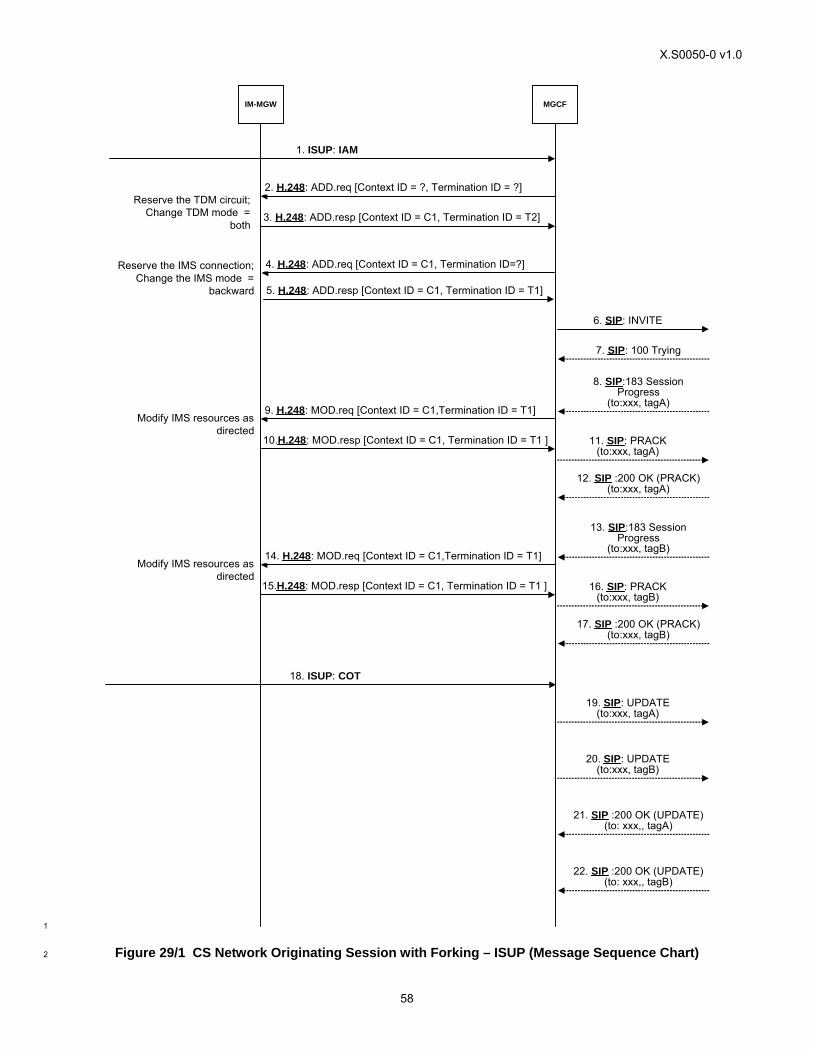
X.S0050-0 v1.0
58
IM-MGW MGCF
6. SIP: INVITE
7. SIP: 100 Trying
1. ISUP: IAM
3. H.248: ADD.resp [Context ID = C1, Termination ID = T2]
4. H.248: ADD.req [Context ID = C1, Termination ID=?]
5. H.248: ADD.resp [Context ID = C1, Termination ID = T1]
8. SIP:183 SessionProgress
(to:xxx, tagA)
11. SIP: PRACK(to:xxx, tagA)
12. SIP :200 OK (PRACK)(to:xxx, tagA)
9. H.248: MOD.req [Context ID = C1,Termination ID = T1]
10.H.248: MOD.resp [Context ID = C1, Termination ID = T1 ]
19. SIP: UPDATE(to:xxx, tagA)
21. SIP :200 OK (UPDATE)(to: xxx,, tagA)
18. ISUP: COT
Reserve the TDM circuit;Change TDM mode =
both
Reserve the IMS connection;Change the IMS mode =
backward
Modify IMS resources asdirected
13. SIP:183 SessionProgress
(to:xxx, tagB)
16. SIP: PRACK(to:xxx, tagB)
17. SIP :200 OK (PRACK)(to:xxx, tagB)
14. H.248: MOD.req [Context ID = C1,Termination ID = T1]
15.H.248: MOD.resp [Context ID = C1, Termination ID = T1 ]
Modify IMS resources asdirected
20. SIP: UPDATE(to:xxx, tagB)
22. SIP :200 OK (UPDATE)(to: xxx,, tagB)
2. H.248: ADD.req [Context ID = ?, Termination ID = ?]
1
Figure 29/1 CS Network Originating Session with Forking – ISUP (Message Sequence Chart) 2
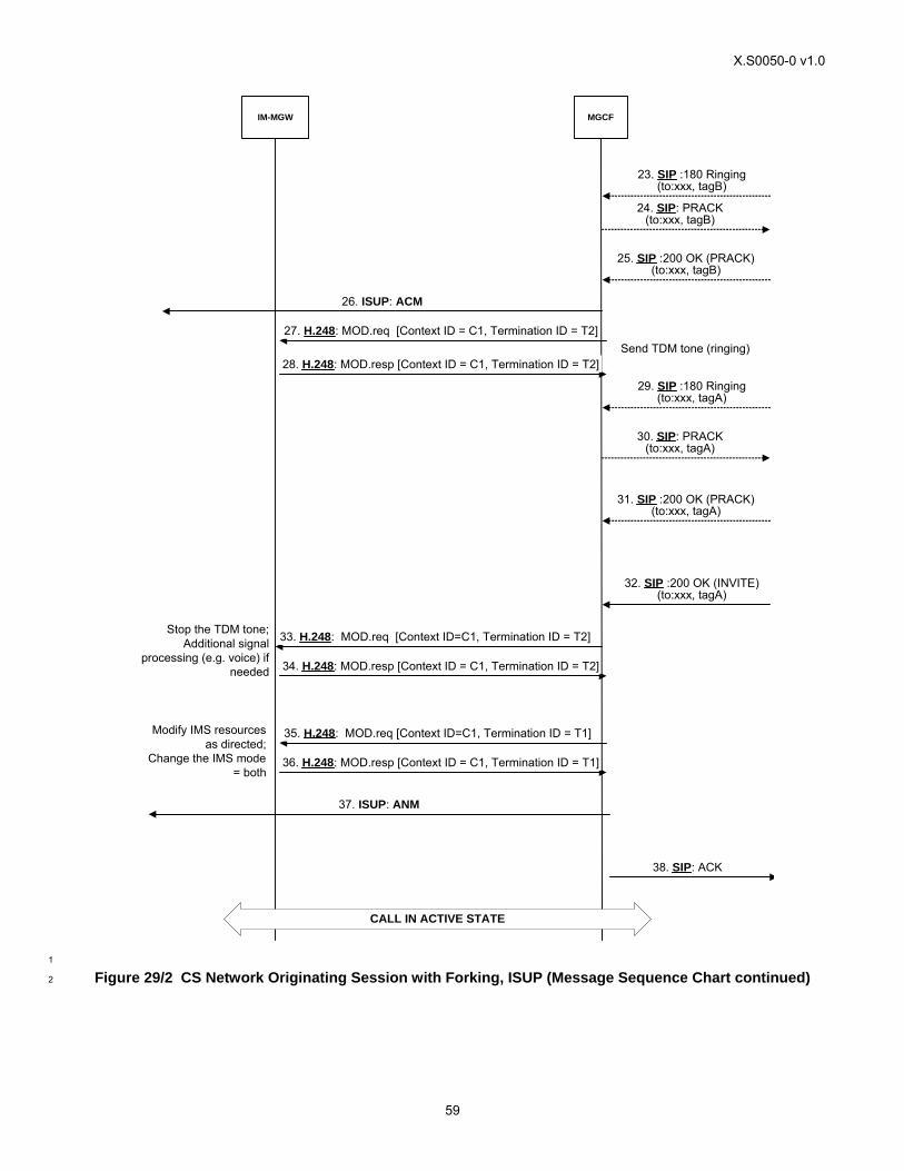
X.S0050-0 v1.0
59
IM-MGW MGCF
33. H.248: MOD.req [Context ID=C1, Termination ID = T2]
34. H.248: MOD.resp [Context ID = C1, Termination ID = T2]
38. SIP: ACK
35. H.248: MOD.req [Context ID=C1, Termination ID = T1]
36. H.248: MOD.resp [Context ID = C1, Termination ID = T1]
37. ISUP: ANM
32. SIP :200 OK (INVITE)(to:xxx, tagA)
CALL IN ACTIVE STATE
Stop the TDM tone;Additional signal
processing (e.g. voice) ifneeded
Modify IMS resourcesas directed;
Change the IMS mode= both
29. SIP :180 Ringing(to:xxx, tagA)
30. SIP: PRACK(to:xxx, tagA)
31. SIP :200 OK (PRACK)(to:xxx, tagA)
23. SIP :180 Ringing(to:xxx, tagB)
24. SIP: PRACK(to:xxx, tagB)
25. SIP :200 OK (PRACK)(to:xxx, tagB)
27. H.248: MOD.req [Context ID = C1, Termination ID = T2]
28. H.248: MOD.resp [Context ID = C1, Termination ID = T2]
26. ISUP: ACM
Send TDM tone (ringing)
1
Figure 29/2 CS Network Originating Session with Forking, ISUP (Message Sequence Chart continued) 2
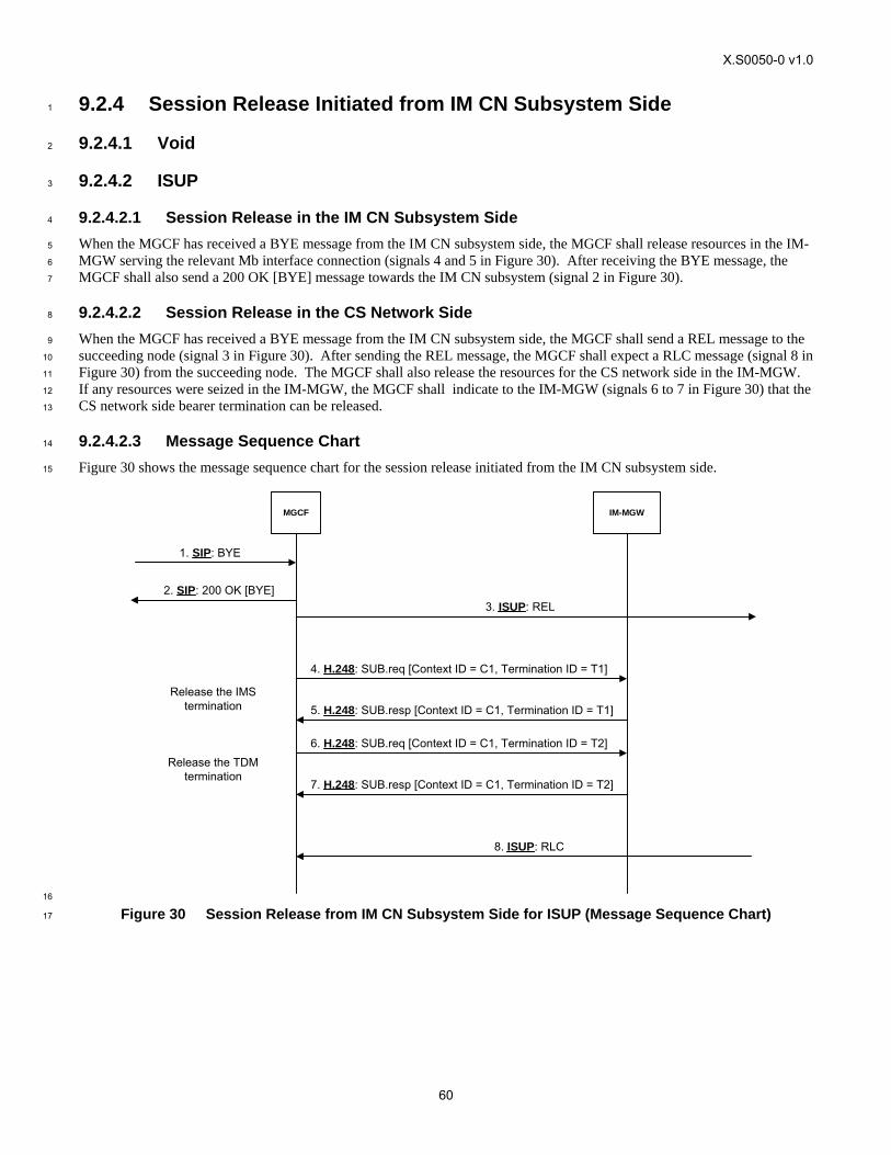
X.S0050-0 v1.0
60
9.2.4 Session Release Initiated from IM CN Subsystem Side 1
9.2.4.1 Void 2
9.2.4.2 ISUP 3
9.2.4.2.1 Session Release in the IM CN Subsystem Side 4
When the MGCF has received a BYE message from the IM CN subsystem side, the MGCF shall release resources in the IM-5
MGW serving the relevant Mb interface connection (signals 4 and 5 in Figure 30). After receiving the BYE message, the 6
MGCF shall also send a 200 OK [BYE] message towards the IM CN subsystem (signal 2 in Figure 30). 7
9.2.4.2.2 Session Release in the CS Network Side 8
When the MGCF has received a BYE message from the IM CN subsystem side, the MGCF shall send a REL message to the 9
succeeding node (signal 3 in Figure 30). After sending the REL message, the MGCF shall expect a RLC message (signal 8 in 10
Figure 30) from the succeeding node. The MGCF shall also release the resources for the CS network side in the IM-MGW. 11
If any resources were seized in the IM-MGW, the MGCF shall indicate to the IM-MGW (signals 6 to 7 in Figure 30) that the 12
CS network side bearer termination can be released. 13
9.2.4.2.3 Message Sequence Chart 14
Figure 30 shows the message sequence chart for the session release initiated from the IM CN subsystem side. 15
MGCF IM-MGW
1. SIP: BYE
4. H.248: SUB.req [Context ID = C1, Termination ID = T1]
5. H.248: SUB.resp [Context ID = C1, Termination ID = T1]
2. SIP: 200 OK [BYE]
Release the IMStermination
6. H.248: SUB.req [Context ID = C1, Termination ID = T2]
7. H.248: SUB.resp [Context ID = C1, Termination ID = T2]
Release the TDMtermination
3. ISUP: REL
8. ISUP: RLC
16
Figure 30 Session Release from IM CN Subsystem Side for ISUP (Message Sequence Chart) 17
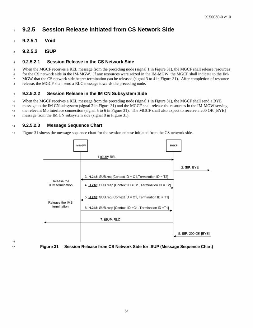
X.S0050-0 v1.0
61
9.2.5 Session Release Initiated from CS Network Side 1
9.2.5.1 Void 2
9.2.5.2 ISUP 3
9.2.5.2.1 Session Release in the CS Network Side 4
When the MGCF receives a REL message from the preceding node (signal 1 in Figure 31), the MGCF shall release resources 5
for the CS network side in the IM-MGW. If any resources were seized in the IM-MGW, the MGCF shall indicate to the IM-6
MGW that the CS network side bearer termination can be released (signal 3 to 4 in Figure 31). After completion of resource 7
release, the MGCF shall send a RLC message towards the preceding node. 8
9.2.5.2.2 Session Release in the IM CN Subsystem Side 9
When the MGCF receives a REL message from the preceding node (signal 1 in Figure 31), the MGCF shall send a BYE 10
message to the IM CN subsystem (signal 2 in Figure 31) and the MGCF shall release the resources in the IM-MGW serving 11
the relevant Mb interface connection (signal 5 to 6 in Figure 31). The MGCF shall also expect to receive a 200 OK [BYE] 12
message from the IM CN subsystem side (signal 8 in Figure 31). 13
9.2.5.2.3 Message Sequence Chart 14
Figure 31 shows the message sequence chart for the session release initiated from the CS network side. 15
1.ISUP: REL
2. SIP: BYE
5. H.248: SUB.req [Context ID = C1, Termination ID = T1]
6. H.248: SUB.resp [Context ID =C1, Termination ID =T1]
3. H.248: SUB.req [Context ID = C1,Termination ID = T2]
4. H.248: SUB.resp [Context ID = C1, Termination ID = T2]
MGCFIM-MGW
7. ISUP: RLC
8. SIP: 200 OK [BYE]
Release theTDM termination
Release the IMStermination
16
Figure 31 Session Release from CS Network Side for ISUP (Message Sequence Chart) 17
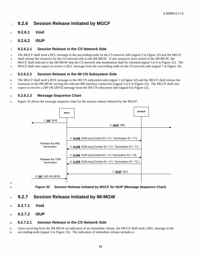
X.S0050-0 v1.0
62
9.2.6 Session Release Initiated by MGCF 1
9.2.6.1 Void 2
9.2.6.2 ISUP 3
9.2.6.2.1 Session Release in the CS Network Side 4
The MGCF shall send a REL message to the succeeding node on the CS network side (signal 2 in Figure 32) and the MGCF 5
shall release the resources for the CS network side in the IM-MGW. If any resources were seized in the IM-MGW, the 6
MGCF shall indicate to the IM-MGW that the CS network side termination shall be released (signal 5 to 6 in Figure 32). The 7
MGCF shall also expect to receive a RLC message from the succeeding node on the CS network side (signal 7 in Figure 32). 8
9.2.6.2.2 Session Release in the IM CN Subsystem Side 9
The MGCF shall send a BYE message to the IM CN subsystem side (signal 1 in Figure 32) and the MGCF shall release the 10
resources in the IM-MGW serving the relevant Mb interface connection (signal 5 to 6 in Figure 32). The MGCF shall also 11
expect to receive a 200 OK [BYE] message from the IM CN subsystem side (signal 8 in Figure 32). 12
9.2.6.2.3 Message Sequence Chart 13
Figure 32 shows the message sequence chart for the session release initiated by the MGCF. 14
MGCF IM-MGW
1. SIP: BYE
8. SIP: 200 OK [BYE]
7. ISUP: RLC
2. ISUP: REL
3. H.248: SUB.req [Context ID = C1, Termination ID = T1]
4. H.248: SUB.resp [Context ID = C1, Termination ID = T1]Release the IMS
termination
5. H.248: SUB.req [Context ID = C1,Termination ID = T2]
6. H.248: SUB.resp [Context ID = C1, Termination ID = T2 ]Release the TDM
termination
15
Figure 32 Session Release Initiated by MGCF for ISUP (Message Sequence Chart) 16
9.2.7 Session Release Initiated by IM-MGW 17
9.2.7.1 Void 18
9.2.7.2 ISUP 19
9.2.7.2.1 Session Release in the CS Network Side 20
Upon receiving from the IM-MGW an indication of an immediate release, the MGCF shall send a REL message to the 21
succeeding node (signal 3 in Figure 33). The indication of immediate release includes a: 22
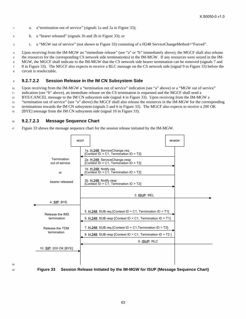
X.S0050-0 v1.0
63
a. a“termination out of service” (signals 1a and 2a in Figure 33); 1
b. a “bearer released” (signals 1b and 2b in Figure 33); or 2
c. a “MGW out of service” (not shown in Figure 33) consisting of a H248 ServiceChangeMethod=“Forced”. 3
Upon receiving from the IM-MGW an “immediate release” (see “a” or “b” immediately above), the MGCF shall also release 4
the resources for the corresponding CS network side termination(s) in the IM-MGW. If any resources were seized in the IM-5
MGW, the MGCF shall indicate to the IM-MGW that the CS network side bearer termination can be removed (signals 7 and 6
8 in Figure 33). The MGCF also expects to receive a RLC message on the CS network side (signal 9 in Figure 33) before the 7
circuit is reselectable. 8
9.2.7.2.2 Session Release in the IM CN Subsystem Side 9
Upon receiving from the IM-MGW a “termination out of service” indication (see “a” above) or a “MGW out of service” 10
indication (see “b” above), an immediate release on the CS termination is requested and the MGCF shall send a 11
BYE/CANCEL message to the IM CN subsystem side (signal 4 in Figure 33). Upon receiving from the IM-MGW a 12
“termination out of service” (see “a” above) the MGCF shall also release the resources in the IM-MGW for the corresponding 13
terminations towards the IM CN subsystem (signals 5 and 6 in Figure 33). The MGCF also expects to receive a 200 OK 14
[BYE] message from the IM CN subsystem side (signal 10 in Figure 33). 15
9.2.7.2.3 Message Sequence Chart 16
Figure 33 shows the message sequence chart for the session release initiated by the IM-MGW. 17
MGCF IM-MGW
4. SIP: BYE
10. SIP: 200 OK [BYE]
1a. H.248: ServiceChange.req[Context ID = C1, Termination ID = T2]
2a. H.248: ServiceChange.resp [Context ID = C1, Termination ID = T2]
Termination out of service
9. ISUP: RLC
3. ISUP: REL
5. H.248: SUB.req [Context ID = C1, Termination ID = T1]
6. H.248: SUB.resp [Context ID = C1, Termination ID = T1]
7. H.248: SUB.req [Context ID = C1,Termination ID = T2]
8. H.248: SUB.resp [Context ID = C1, Termination ID = T2 ]
Release the IMS termination
Release the TDM termination
1b. H.248: Notify.req[Context ID = C1, Termination ID = T2]
2b. H.248: Notify.resp [Context ID = C1, Termination ID = T2]
bearer released
or
18
Figure 33 Session Release Initiated by the IM-MGW for ISUP (Message Sequence Chart) 19
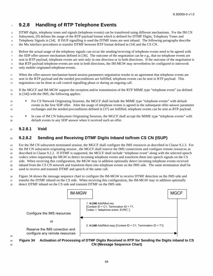
X.S0050-0 v1.0
64
9.2.8 Handling of RTP Telephone Events 1
DTMF digits, telephony tones and signals (telephone events) can be transferred using different mechanisms. For the IM CN 2
Subsystem, [9] defines the usage of the RTP payload format which is defined for DTMF Digits, Telephony Tones and 3
Telephony Signals in [34]. If ISUP signalling is used the DTMF tones are sent inband. The following paragraphs describe 4
the Mn interface procedures to transfer DTMF between RTP format defined in [34] and the CS CN. 5
Before the actual usage of the telephony signals can occur the sending/receiving of telephone events need to be agreed with 6
the SDP offer-answer mechanism defined in [36]. The outcome of the negotiation can be e.g., that no telephone events are 7
sent in RTP payload, telephone events are sent only in one direction or in both directions. If the outcome of the negotiation is 8
that RTP payload telephone-events are sent in both directions, the IM-MGW may nevertheless be configured to interwork 9
only mobile originated telephone-events. 10
When the offer-answer mechanism based session parameters negotiation results in an agreement that telephone events are 11
sent in the RTP payload and the needed preconditions are fulfilled, telephone events can be sent in RTP payload. This 12
negotiation can be done at call control signalling phase or during an ongoing call. 13
If the MGCF and IM-MGW support the reception and/or transmission of the RTP MIME type “telephone event” (as defined 14
in [34]) with the IMS, the following applies: 15
For CS Network Originating Sessions, the MGCF shall include the MIME type “telephone events” with default 16
events in the first SDP offer. After the usage of telephone events is agreed in the subsequent offer-answer parameter 17
exchanges and the needed preconditions defined in [37] are fulfilled, telephone events can be sent as RTP payload. 18
In case of IM CN Subsystem Originating Sessions, the MGCF shall accept the MIME type “telephone events” with 19
default events in any SDP answer when it received such an offer. 20
9.2.8.1 Void 21
9.2.8.2 Sending and Receiving DTMF Digits Inband to/from CS CN (ISUP) 22
For the IM CN subsystem terminated session, the MGCF shall configure the IMS resources as described in Clause 9.2.3. For 23
the IM CN subsystem originating session , the MGCF shall reserve the IMS connections and configure remote resources as 24
described in Clause 9.2.2. If DTMF is supported, the MGCF shall include “telephone event” along with the selected speech 25
codecs when requesting the MGW to detect incoming telephone events and transform them into speech signals on the CS 26
side. When receiving this configuration, the MGW may in addition optionally detect incoming telephone events received 27
inband from the CS CN network and transform them into telephone events on the IMS side. The same termination shall be 28
used to receive and transmit DTMF and speech of the same call. 29
Figure 34 shows the message sequence chart to configure the IM-MGW to receive DTMF detection on the IMS side and 30
transfer the DTMF inband on the CS side. When receiving this configuration, the IM-MGW may in addition optionally 31
detect DTMF inband on the CS side and transmit DTMF on the IMS side. 32
1. H.248 Add/Mod.req [Context ID = C1, Termination ID = T1, Codec = “telephone event, EVRC”,]
IM-MGW MGCF
2. H.248 Add/Mod.resp [Context ID = C1, Termination ID = T1]
Configure the IMS resources
or
Reserve the IMS conection and configure any remote resources
33
Figure 34 Activation of Processing of DTMF Digits Received in RTP for Sending the Digits inband to CS 34
CN (Message Sequence Chart) 35
X.S0050-0 v1.0
65
9.2.9 Session Hold Initiated from IM CN Subsystem 1
The network model in the clause 9.2.1 shall apply here. 2
9.2.9.1 Hold Request 3
When the IMS network makes a hold request by sending an UPDATE or re-INVITE message (signal 1 of Figure 35), the 4
MGCF shall request the IM-MGW to suspend sending media towards the IMS side by changing the through-connection of 5
the IM CN subsystem side termination to 'not through-connected' (signal 2 of Figure 35). If the IMS side provides modified 6
SDP RR or RS bandwidth modifiers, as specified in [59], within the hold request, the MGCF shall configure the IMS 7
resources to forward this information to the IM-MGW (not depicted in Figure 35, but may be combined with signal 2). The 8
MGCF shall send a CPG (Hold) message to the succeeding CS network node to indicate that the session is on hold (signal 4 9
of Figure 35). Simultaneously a SIP message acknowledging the Hold request is sent to the IMS side (signal 7 of Figure 35, 10
acknowledged by signal 7.a if the INVITE method is used). Announcements may be applied to the party on hold, depending 11
on the held party’s status (for ISUP, signal 5 in Figure 35). The hold operation shall not block RTCP flows. 12
9.2.9.2 Resume Request 13
When the IMS network makes a request to retrieve the session on hold by sending an UPDATE or re-INVITE message 14
(signal 8 of Figure 35), the MGCF shall request the IM-MGW to re-establish communication towards the IMS network by 15
changing the through-connection of the IM CN subsystem side termination to both-way through-connected (signal 11 of 16
Figure 35). If the IMS side provides modified SDP RR or RS bandwidth modifiers, as specified in [59], within the retrieve 17
request, the MGCF shall configure the IMS resources to forward this information to the IM-MGW (not depicted in Figure 35, 18
but may be combined with signal 11). Possible announcements to the party on hold shall be stopped (for ISUP, signal 9 in 19
Figure 35). The MGCF shall send a CPG (Retrieve) message to the succeeding CS network node to indicate that the session 20
is retrieved (signal 13 of Figure 35). 21
9.2.9.3 Message Sequence Chart 22
Figure 35 shows the message sequence chart for the call hold and hold-release procedures. 23
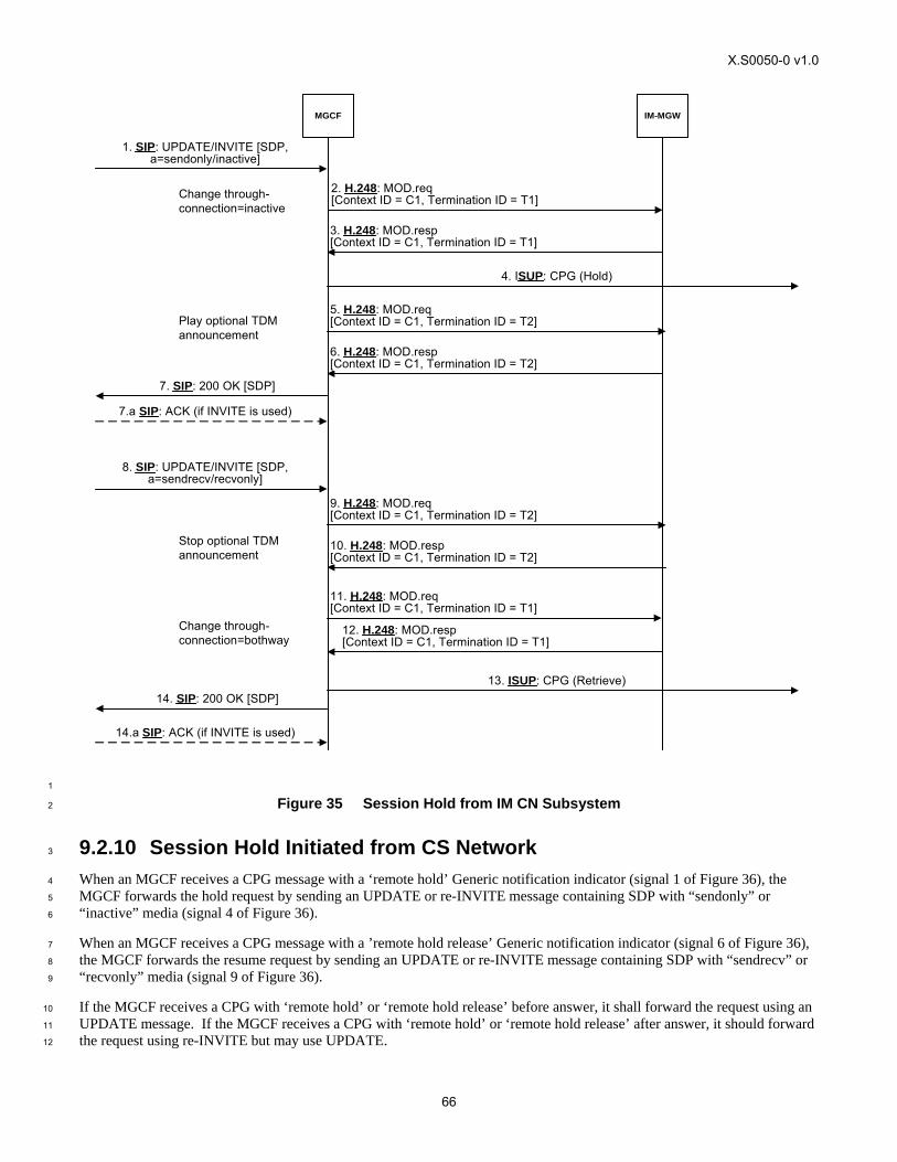
X.S0050-0 v1.0
66
MGCF IM-MGW
4. ISUP: CPG (Hold)
2. H.248: MOD.req [Context ID = C1, Termination ID = T1]
3. H.248: MOD.resp [Context ID = C1, Termination ID = T1]
11. H.248: MOD.req [Context ID = C1, Termination ID = T1]
12. H.248: MOD.resp [Context ID = C1, Termination ID = T1]
7. SIP: 200 OK [SDP]
1. SIP: UPDATE/INVITE [SDP, a=sendonly/inactive]
8. SIP: UPDATE/INVITE [SDP, a=sendrecv/recvonly]
13. ISUP: CPG (Retrieve)14. SIP: 200 OK [SDP]
7.a SIP: ACK (if INVITE is used)
14.a SIP: ACK (if INVITE is used)
5. H.248: MOD.req [Context ID = C1, Termination ID = T2]
9. H.248: MOD.req [Context ID = C1, Termination ID = T2]
Play optional TDM announcement
Stop optional TDM announcement
Change through-connection=inactive
Change through-connection=bothway
6. H.248: MOD.resp [Context ID = C1, Termination ID = T2]
10. H.248: MOD.resp [Context ID = C1, Termination ID = T2]
1
Figure 35 Session Hold from IM CN Subsystem 2
9.2.10 Session Hold Initiated from CS Network 3
When an MGCF receives a CPG message with a ‘remote hold’ Generic notification indicator (signal 1 of Figure 36), the 4
MGCF forwards the hold request by sending an UPDATE or re-INVITE message containing SDP with “sendonly” or 5
“inactive” media (signal 4 of Figure 36). 6
When an MGCF receives a CPG message with a ’remote hold release’ Generic notification indicator (signal 6 of Figure 36), 7
the MGCF forwards the resume request by sending an UPDATE or re-INVITE message containing SDP with “sendrecv” or 8
“recvonly” media (signal 9 of Figure 36). 9
If the MGCF receives a CPG with ‘remote hold’ or ‘remote hold release’ before answer, it shall forward the request using an 10
UPDATE message. If the MGCF receives a CPG with ‘remote hold’ or ‘remote hold release’ after answer, it should forward 11
the request using re-INVITE but may use UPDATE. 12
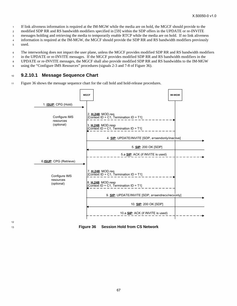
X.S0050-0 v1.0
67
If link aliveness information is required at the IM-MGW while the media are on hold, the MGCF should provide to the 1
modified SDP RR and RS bandwidth modifiers specified in [59] within the SDP offers in the UPDATE or re-INVITE 2
messages holding and retrieving the media to temporarily enable RTCP while the media are on hold. If no link aliveness 3
information is required at the IM-MGW, the MGCF should provide the SDP RR and RS bandwidth modifiers previously 4
used. 5
The interworking does not impact the user plane, unless the MGCF provides modified SDP RR and RS bandwidth modifiers 6
in the UPDATE or re-INVITE messages. If the MGCF provides modified SDP RR and RS bandwidth modifiers in the 7
UPDATE or re-INVITE messages, the MGCF shall also provide modified SDP RR and RS bandwidths to the IM-MGW 8
using the “Configure IMS Resources” procedures (signals 2-3 and 7-8 of Figure 36). 9
9.2.10.1 Message Sequence Chart 10
Figure 36 shows the message sequence chart for the call hold and hold-release procedures. 11
MGCF IM-MGW
1. ISUP: CPG (Hold)
2. H.248: MOD.req [Context ID = C1, Termination ID = T1]
3. H.248: MOD.resp [Context ID = C1, Termination ID = T1]
5. SIP: 200 OK [SDP]
4. SIP: UPDATE/INVITE [SDP, a=sendonly/inactive]
6.ISUP: CPG (Retrieve)
Configure IMS resources(optional)
7. H.248: MOD.req [Context ID = C1, Termination ID = T1]
8. H.248: MOD.resp [Context ID = C1, Termination ID = T1]
10. SIP: 200 OK [SDP]
9. SIP: UPDATE/INVITE [SDP, a=sendrecv/recvonly]
Configure IMS resources(optional)
5.a SIP: ACK (if INVITE is used)
10.a SIP: ACK (if INVITE is used)
12
Figure 36 Session Hold from CS Network 13
![[MS-SIPREGE]: Session Initiation Protocol (SIP ...... · Session Initiation Protocol (SIP) Registration Extensions Intellectual Property Rights Notice for Open Specifications Documentation](https://img.pdfslide.us/doc/110x75/5f0cae0d7e708231d4369a32/ms-siprege-session-initiation-protocol-sip-session-initiation-protocol.jpg)


![[MS-SIP]: Session Initiation Protocol ExtensionsMS-SIP]-160714.pdf · [MS-SIP]: Session Initiation Protocol Extensions ... sip. . . .](https://img.pdfslide.us/doc/110x75/5f144311cb0953247f1ddd57/ms-sip-session-initiation-protocol-extensions-ms-sip-160714pdf-ms-sip.jpg)

![[MS-SIP]: Session Initiation Protocol Extensions · [MS-SIP]: Session Initiation Protocol Extensions ... sending a](https://img.pdfslide.us/doc/110x75/5e7f871abb290110395780f1/ms-sip-session-initiation-protocol-extensions-ms-sip-session-initiation-protocol.jpg)


![[MS-SIPCOMP]: Session Initiation Protocol (SIP ...interoperability.blob.core.windows.net/...SIPCOMP/[MS-SIPCOMP]-150904.pdf · Session Initiation Protocol (SIP): An application-layer](https://img.pdfslide.us/doc/110x75/5e7f88d08d58df3d9a0df2da/ms-sipcomp-session-initiation-protocol-sip-ms-sipcomp-150904pdf-session.jpg)