Embed Size (px)
Citation preview
L08 - MARIE 10/3/2016
1
ISE218 – Fundamentals of Information Technology
SESSION 8 – MARIEReading: Sections 4.8-4.11
Objectives• Better understand the operations of a computer by examining a very simple processor that includes many important features of a processor
• Understand the major components (control unit, registers, memory, ALU, and data path)
• Understand the fetch-decode-execute cycle
2© Robert F. Kelly, 2012-2016
L08 - MARIE 10/3/2016
2
MARIE• Machine Architecture that is Really Intuitive and Easy (MARIE)
• Simple computer that illustrates hardware concepts
• Enable you to comprehend system architectures that are much more complex
3© Robert F. Kelly, 2012-2016
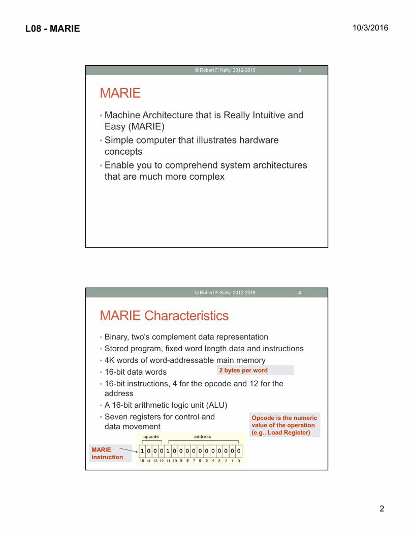
MARIE Characteristics• Binary, two's complement data representation• Stored program, fixed word length data and instructions• 4K words of word-addressable main memory• 16-bit data words• 16-bit instructions, 4 for the opcode and 12 for the
address• A 16-bit arithmetic logic unit (ALU)• Seven registers for control and
data movement
2 bytes per word2 bytes per word
Opcode is the numeric value of the operation (e.g., Load Register)
Opcode is the numeric value of the operation (e.g., Load Register)
MARIE instructionMARIE instruction
4© Robert F. Kelly, 2012-2016
L08 - MARIE 10/3/2016
3
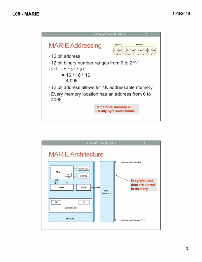
MARIE Addressing• 12 bit address• 12 bit binary number ranges from 0 to 212-1• 212 = 24 * 24 * 24
= 16 * 16 * 16= 4,096
• 12 bit address allows for 4K addressable memory• Every memory location has an address from 0 to 4095
Remember, memory is usually byte addressableRemember, memory is usually byte addressable
5© Robert F. Kelly, 2012-2016
© Robert F. Kelly, 2012-2016
MARIE Architecture
Programs and data are stored in memory
Programs and data are stored in memory
6

L08 - MARIE 10/3/2016
4
MARIE Registers …• Accumulator(AC) - 16-bit register that holds a conditional operator (e.g., "less than") or one operand of a two-operand instruction
• Memory address register (MAR) - 12-bit register that holds a memory address (an instruction or the operand of an instruction)
• Memory buffer register (MBR) - 16-bit register that holds data either• after its retrieval from memory or • before its placement in memory
Operand is a parameter to the operationOperand is a parameter to the operation
7© Robert F. Kelly, 2012-2016
… MARIE Registers• Program counter, PC, a 12-bit register that holds the address of the next program instruction to be executed
• Instruction register, IR, which holds an instruction immediately preceding its execution
• Input register, InREG, an 8-bit register that holds data read from an input device
• Output register, OutREG, an 8-bit register, that holds data that is ready for the output device
8© Robert F. Kelly, 2012-2016
L08 - MARIE 10/3/2016
5
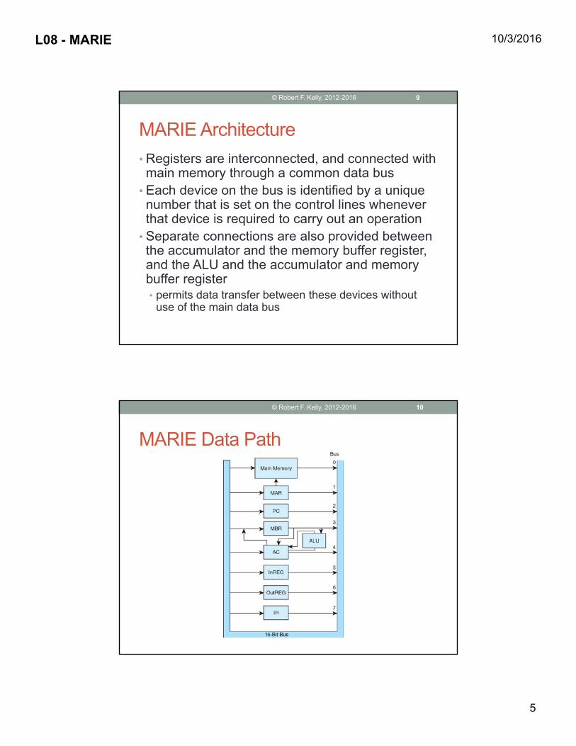
MARIE Architecture• Registers are interconnected, and connected with main memory through a common data bus
• Each device on the bus is identified by a unique number that is set on the control lines whenever that device is required to carry out an operation
• Separate connections are also provided between the accumulator and the memory buffer register, and the ALU and the accumulator and memory buffer register• permits data transfer between these devices without
use of the main data bus
9© Robert F. Kelly, 2012-2016
MARIE Data Path
10© Robert F. Kelly, 2012-2016
L08 - MARIE 10/3/2016
6
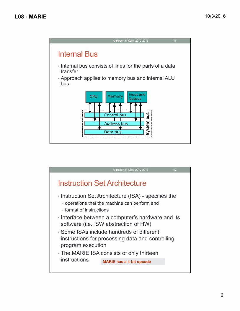
Internal Bus• Internal bus consists of lines for the parts of a data transfer
• Approach applies to memory bus and internal ALU bus
11© Robert F. Kelly, 2012-2016
Instruction Set Architecture• Instruction Set Architecture (ISA) - specifies the
• operations that the machine can perform and • format of instructions
• Interface between a computer’s hardware and its software (i.e., SW abstraction of HW)
• Some ISAs include hundreds of different instructions for processing data and controlling program execution
• The MARIE ISA consists of only thirteen instructions MARIE has a 4-bit opcodeMARIE has a 4-bit opcode
12© Robert F. Kelly, 2012-2016
L08 - MARIE 10/3/2016
7
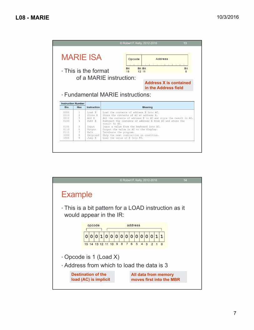
MARIE ISA• This is the format
of a MARIE instruction:
• Fundamental MARIE instructions:
Address X is contained in the Address fieldAddress X is contained in the Address field
13© Robert F. Kelly, 2012-2016
Example• This is a bit pattern for a LOAD instruction as it would appear in the IR:
• Opcode is 1 (Load X)• Address from which to load the data is 3
Destination of the load (AC) is implicitDestination of the load (AC) is implicit
All data from memory moves first into the MBRAll data from memory moves first into the MBR
14© Robert F. Kelly, 2012-2016
L08 - MARIE 10/3/2016
8
© Robert F. Kelly, 2012-2016
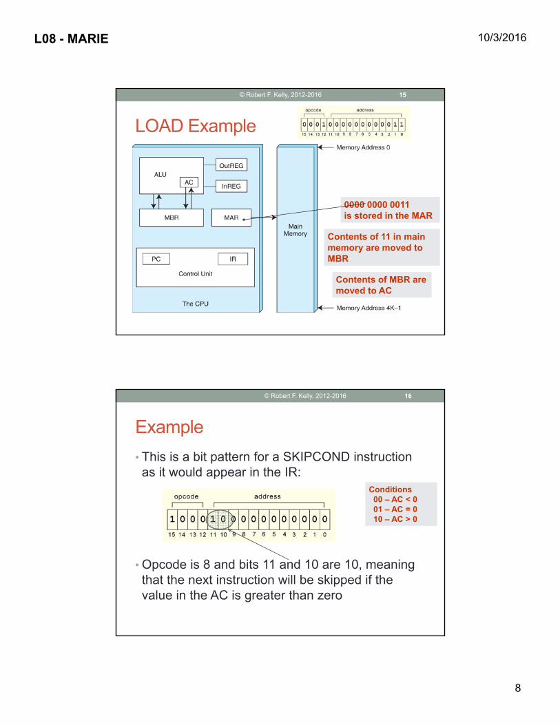
LOAD Example
0000 0000 0011is stored in the MAR0000 0000 0011is stored in the MAR
Contents of 11 in main memory are moved to MBR
Contents of 11 in main memory are moved to MBR
Contents of MBR are moved to ACContents of MBR are moved to AC
15
Example• This is a bit pattern for a SKIPCOND instruction as it would appear in the IR:
• Opcode is 8 and bits 11 and 10 are 10, meaning that the next instruction will be skipped if the value in the AC is greater than zero
Conditions00 – AC < 001 – AC = 010 – AC > 0
Conditions00 – AC < 001 – AC = 010 – AC > 0
16© Robert F. Kelly, 2012-2016
L08 - MARIE 10/3/2016
9
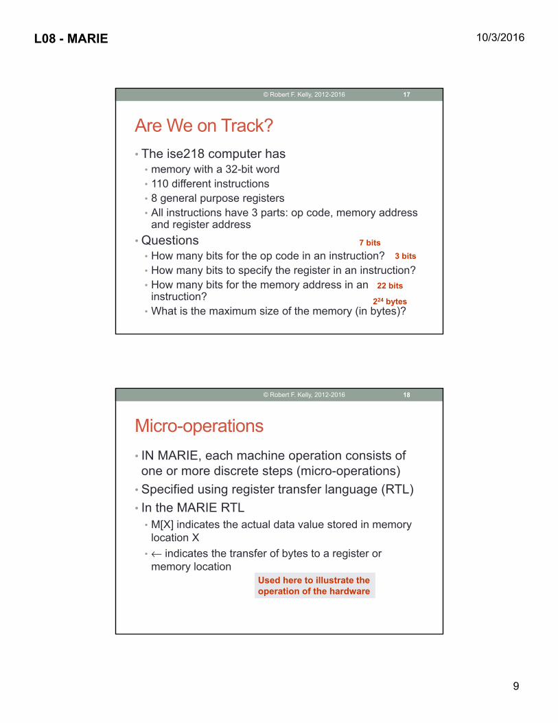
Are We on Track?• The ise218 computer has
• memory with a 32-bit word• 110 different instructions• 8 general purpose registers• All instructions have 3 parts: op code, memory address
and register address• Questions
• How many bits for the op code in an instruction?• How many bits to specify the register in an instruction?• How many bits for the memory address in an
instruction?• What is the maximum size of the memory (in bytes)?
7 bits3 bits
22 bits
224 bytes
17© Robert F. Kelly, 2012-2016
Micro-operations• IN MARIE, each machine operation consists of one or more discrete steps (micro-operations)
• Specified using register transfer language (RTL)• In the MARIE RTL
• M[X] indicates the actual data value stored in memory location X
• ← indicates the transfer of bytes to a register or memory location
Used here to illustrate the operation of the hardwareUsed here to illustrate the operation of the hardware
18© Robert F. Kelly, 2012-2016

L08 - MARIE 10/3/2016
10
Microcode• A layer of hardware-level instructions used to execute machine code
• Resides in special high-speed memory • Usually not visible to a programmer• A simple way to implement a complex architecture
• Examples• Classic example – IBM 360• Current game programming systems
Fewer current processors are microprogram controlled
Fewer current processors are microprogram controlled
19© Robert F. Kelly, 2012-2016
Sample RTL• The RTL for the LOAD X instruction is:• MAR ← X (load address
into the memory address register)
• MBR ← M[MAR] (move data stored at MAR address into MBR)
• AC ← MBR (move MBR data to accumulator)
Text has RTL code for all MARIE instructionsText has RTL code for all MARIE instructions
20© Robert F. Kelly, 2012-2016

L08 - MARIE 10/3/2016
11
Sample RTL• RTL for the ADD X instruction is:• MAR ← X (load address
into the memory address register)
• MBR ← M[MAR] (move data stored at MAR address into MBR)
• AC ← AC + MBR (add data in MBR to accumulator)
21© Robert F. Kelly, 2012-2016
A Simple Program• Consider the simple MARIE program given below. We show a set of instructions and data stored at addresses 100 – 106 (hex):
Address Instruction Memory (binary) Memory (hex)100 Load 104 0001 0001 0000 0100 1104101 Add 105 0011 0001 0000 0101 3105102 Store 106 0010 0001 0000 0110 2106103 Halt 0111 0000 0000 0000 7000104 0000 0000 0010 0011 0023105 1111 1111 1110 1001 FFE9106 0000 0000 0000 0000 0000
22© Robert F. Kelly, 2012-2016

L08 - MARIE 10/3/2016
12
Example• Let’s look at what happens inside the computer when our program runs.
• This is the LOAD 104 instruction:
Recognizes the Load instructionRecognizes the Load instruction
23© Robert F. Kelly, 2012-2016
Initial value of the PC is the location of the first instruction
Initial value of the PC is the location of the first instruction
Example – Next Instruction• ADD 105:
24© Robert F. Kelly, 2012-2016

L08 - MARIE 10/3/2016
13
Are We on Track?• Write the Assembly Language equivalent (using hex for addresses) of the following MARIE machine language instructions
• 0010 0000 0000 0111• 1001 0000 0000 1011• 0011 0000 0000 1001
Store 007 Store 007
Jump 00B
Add 009
25© Robert F. Kelly, 2012-2016
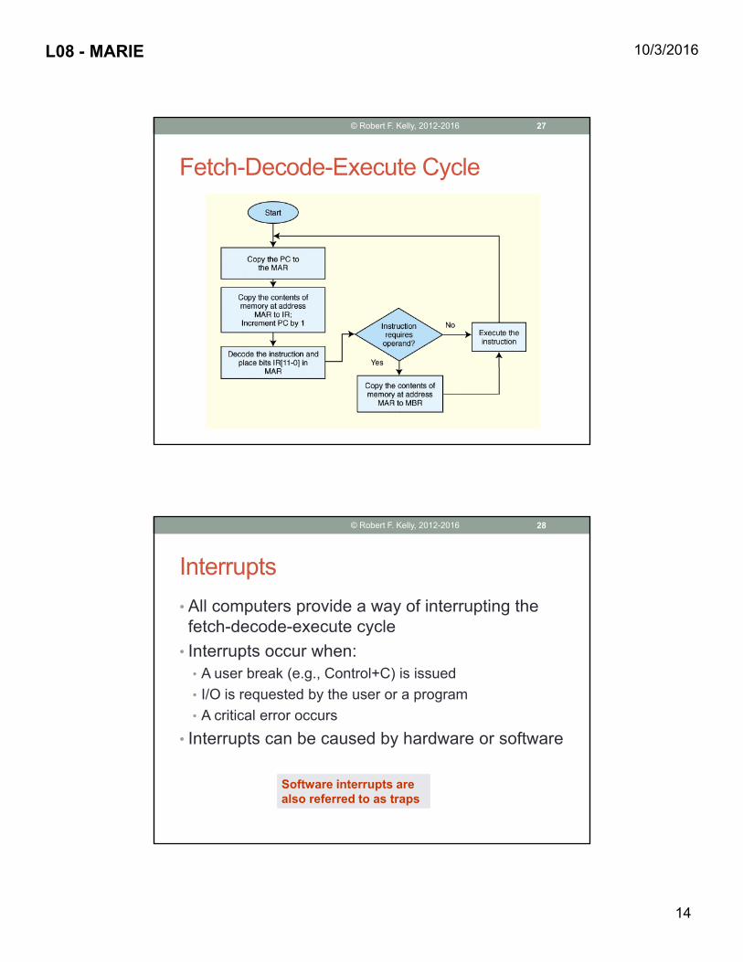
Fetch-Decode-Execute Cycle• Series of steps that a computer carries out for each instruction in the ISA
• Steps1. Fetch an instruction from memory, and place it into
the IR2. Decode the instruction to determine what needs to be
done next (based on leftmost 4 bits of instruction)3. If a memory value (operand) is involved in the
operation, it is retrieved and placed into the MBR4. Execute
26© Robert F. Kelly, 2012-2016
L08 - MARIE 10/3/2016
14
Fetch-Decode-Execute Cycle
27© Robert F. Kelly, 2012-2016
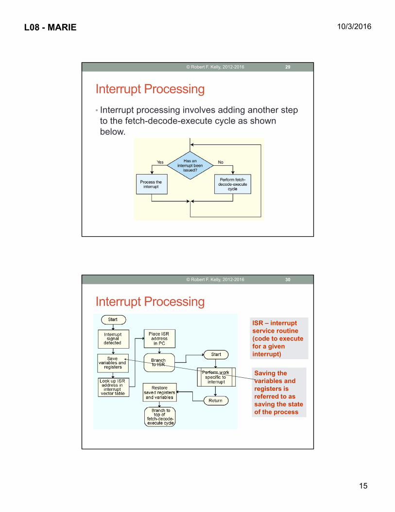
Interrupts• All computers provide a way of interrupting the fetch-decode-execute cycle
• Interrupts occur when:• A user break (e.g., Control+C) is issued• I/O is requested by the user or a program• A critical error occurs
• Interrupts can be caused by hardware or software
Software interrupts are also referred to as trapsSoftware interrupts are also referred to as traps
28© Robert F. Kelly, 2012-2016
L08 - MARIE 10/3/2016
15
Interrupt Processing• Interrupt processing involves adding another step to the fetch-decode-execute cycle as shown below.
29© Robert F. Kelly, 2012-2016
Interrupt ProcessingISR – interrupt service routine (code to execute for a given interrupt)
ISR – interrupt service routine (code to execute for a given interrupt)
Saving the variables and registers is referred to as saving the state of the process
Saving the variables and registers is referred to as saving the state of the process
30© Robert F. Kelly, 2012-2016

L08 - MARIE 10/3/2016
16
Interrupt Handling• It is common to disable all interrupts during the time in which an interrupt is being processed.• Typically, this is achieved by setting a bit in the flags
register• Interrupts that are ignored in this case are called maskable
• Nonmaskable interrupts are those interrupts that must be processed in order to keep the system in a stable condition
More advanced processors support more advanced interrupt handling features
More advanced processors support more advanced interrupt handling features
31© Robert F. Kelly, 2012-2016
Instruction Processing• Interrupts are very useful in processing I/O• MARIE uses a modified form of programmed I/O
• All output is placed in an output register, OutREG• CPU polls the input register, InREG, until input is
sensed • The value is copied into the accumulator
32© Robert F. Kelly, 2012-2016

L08 - MARIE 10/3/2016
17
Have You Satisfied Objectives?• Better understand the operations of a computer by examining a very simple processor that includes many important features of a processor
• Understand the major components(control unit, registers, memory, ALU, and data path
• Understand the fetch-decode-execute cycle
33© Robert F. Kelly, 2012-2016


![Bla(Jan12)-l08 [Cwl] - Tort](https://img.pdfslide.us/doc/110x75/55cf9d55550346d033ad2964/blajan12-l08-cwl-tort.jpg)