Embed Size (px)
Citation preview
Session 111
Plant Experiences
III- l The Evaluation of IGSCC Problems of Stainless Steel Piping
in Taiwan BWR-6 Nuclear Power Plant
Kuen Ting, Department of Nuclear Regulation Atomic Energy
Council,Taiwan, Republic of China
The Evaluation of IGSCC Problems of Stainless Steel Piping in Taiwan BWR-6 Nuclear Power Plant
Kuen Ting
Department of Nuclear Regulation Atomic Energy Council
Republic of China
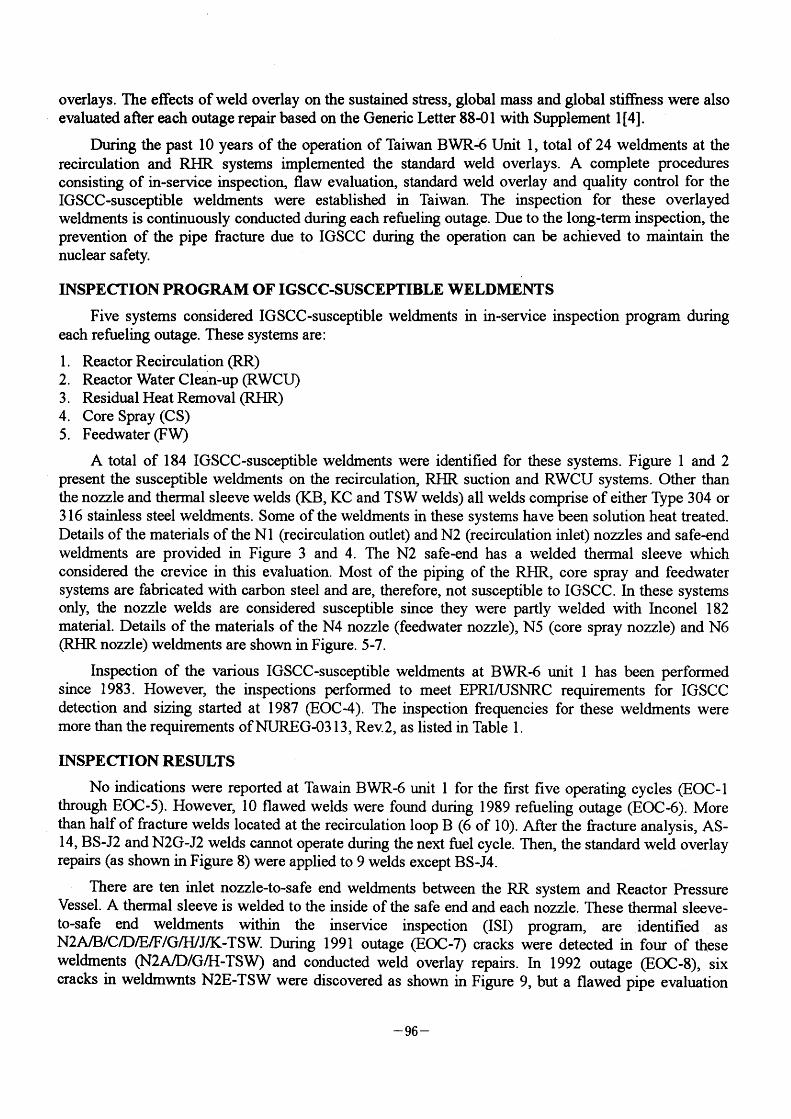
ABSTRACT Taiwan BWR-6 Kuosheng Nuclear Power Plant Unit I implemented the inspeotion of the IGSCC-susoeptible wekhnents. of stainless steel piping in the reactor recirculation, reactor water clean-up, residual heat removal, core spray and feedwater systems. The purpose of this paper is to present the status of the fraoture problems in the weldments. The crack growth analysis due to IGSCC and the standard weld overlay design based on the ASME Code Section XI and NUREG-03 1 3 Rev. 2 for the fracture weldments are discussed in detail. Then, the contingent programs including the inspection program, fracture evaluation, the standard weld overlay are completely established to prevent the pipe
break during the reactor operation.
INTRODUCTION The objeetive of this paper is to present the intergranular stress corrosion cracking GGSCC) status
ofthe primary coolant system at BWR-6 Nuclear Power Station (NPS) unit I in Taiwan. This work was aehieved by identifying all the IGSCC-susceptible systems and the associated weldments. Following the procedures of inspeotion, evaluation and repair are based on the requirements of the United States Nuclear Regulatory Commission (USNRC) Report NUREG-0313. Rev. 2[l] and Generic Letter 88-O I [2] .
An inspections have been performed on the various IGSCC-susceptible weldments at BWR-6 NPS unit I in Taiwan since 1 983. The inspections, since 1 987 (EOC-4), have been performed to the requirements of NUREG-03 13, Rev.2. The total of 184 weldments which are contained in reactor recireulation, reaetor water clean-up, residual heat removal, core spray and feedwater systems are categorized as five groups. However, the inspection frequencies for the various weldment categories were more than the NUREG-03 1 3 requirements during the past I O years of operation in Taiwan. When a flawed weld is identified during inservice inspection, the flaw evaluation may be performed to meet the requirements of ASME Code Section XI in lieu of repair to justify continued operation for a specified evaluation period. This evaluation is based on the linear elastio fracture mechanics to Galculate
the IGSCC growih. If the crack growth exceeds the allowable critical length and depth, identified IGSCC in stainless steel may be used standard weld overlay for long-tenn repair. The design of the standard weld overlay is based on the net section collapse conoept. Significant field, and experimental
evidenGe has been assembled to meet ASME Code Case 504-1 [3] for the long term repairs of weld
- 95 ~
overlays. The effeGts of weld overlay on the sustained stress, global mass and global stiffness were also
evaluated after each outage repair based on the Generic Letter 88~)1 with Supplement I [4].
During the past I O years of the operation of Taiwan BWR~5 Unit I , total of 24 weldments at the
recirculation and RHR systems implemented the standard weld overlays. A Gomplete procedures consisting of in-service inspection, flaw evaluation, standard weld overlay and quality control for the
IGSCC-susceptible weldments were established in Taiwan. The inspection for these overlayed weldments is continuously conducted during each refueling outage. Due to the long-term inspection, the prevention of the pipe fracture due to IGSCC during the operation can be achieved to maintain the nuclear safety.
INSPECTION PROGRAM OF IGSCC-SUSCEPTIBLE WELDMENTS Five systems considered IGSCC-susceptible weldments in in-service inspection program during
each refueling outage. These systems are :
l . Reactor Recirculation (RR:)
2 . Reactor Water Clean-up (RWCU) 3 . Residual Heat Removal (RHR;) 4. Core Spray (CS) 5. Feedwater (FW)
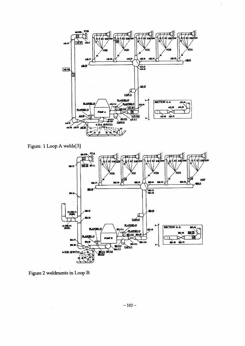
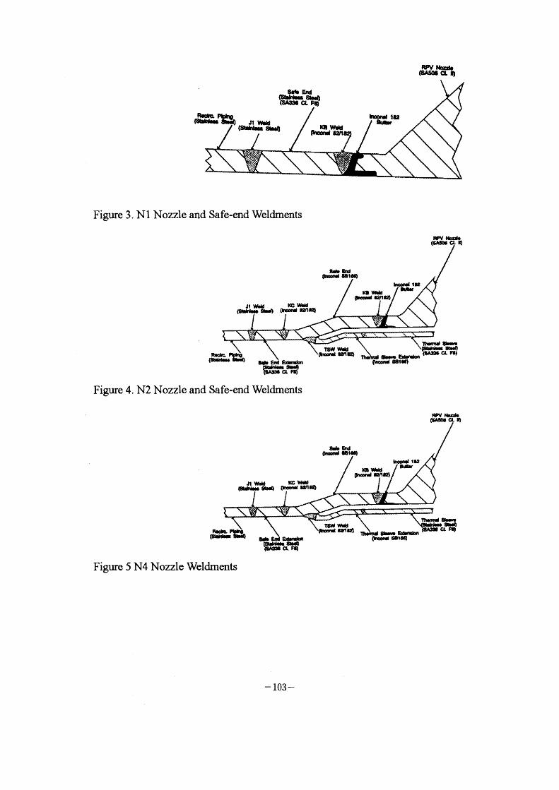
A total of 1 84 IGSCC-susceptible weldments were identified for these systems. Figure I and 2 present the susGeptible weldments on the reoirculation, IuJR suction and RWCU systems. Other than the nozzle and thermal sleeve welds (KB, KC and TSW welds) all welds comprise of either Type 304 or 3 1 6 stamless steel weldments. Some of the weldments in these systems have been solution heat treated. Details of the materials of the Nl (recirculation outlet) and N2 (recirculation inlet) nozzles and safe-end
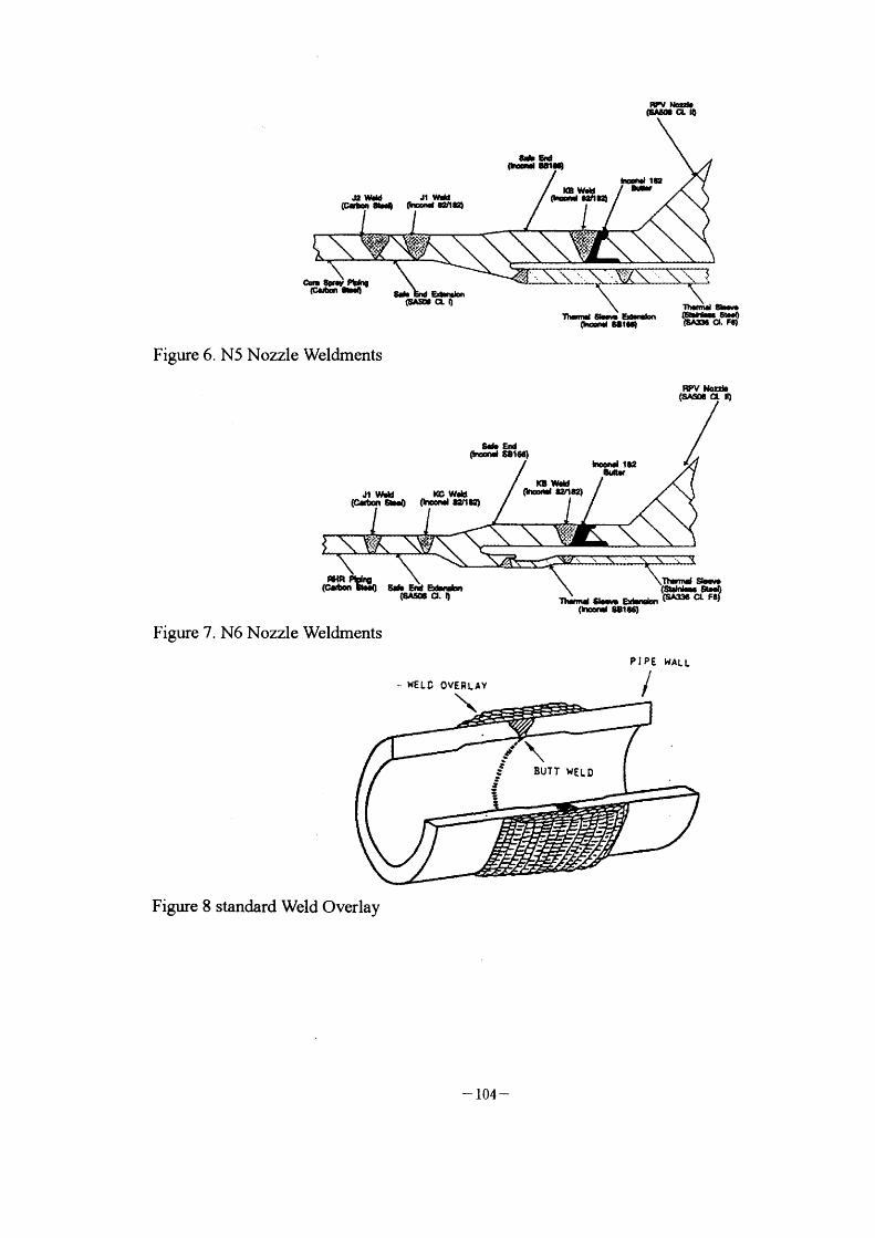
weldments are provided in Figure 3 and 4. The N2 safe-end has a welded thermal sleeve which considered the crevice in this evaluation. Most of the piping of the RHR, core spray and feedwater systems are fabricated with Garbon steel and are, therefore, not susceptible to IGSCC. In these systems only, the nozzle welds are considered susceptible since they were partly welded with Inconel 1 82 material. Details of the materials of the N4 nozzle (feedwater nozzle), N5 (core spray nozzle) and N6 (RHR nozzle) weldments are shown in Figure. 5-7.
Inspection of the various IGSCC-susceptible weldments at BWR-6 unit I has bcen performed since 1 983. However, the inspections performed to meet EPRI/USNRC requirements for IGSCC detection and sizing started at 1 987 (EOC-4). The inspection frequencies for these weldrnents were more than the requirements ofNUREG-03 1 3, Rev.2, as listed in Table I .
INSPEcrION RESIJIJTS No indications were reported at Tawain BWR-6 unit I for the flfst frve operating cycles (EOC-l
through EOC-5). However, 10 flawed welds were found during 1 989 refueling outage (EOC-6). More than half of fracture welds located at the recirculation loop B (6 of I O). After the fracture analysis, AS-
l 4, BS-J2 and N2G-J2 welds cannot operate during the next fuel cycle. Then, the standard weld overlay repairs (as shown in Figure 8) were applied to 9 welds except BS-J4.
There are ten mlet nozzle-to-safe end weldrnents between the RR system and Reactor Pressure Vessel. A thermal sleeve is welded to the inside of the safe end and each nozzle. These thermal sleeve-
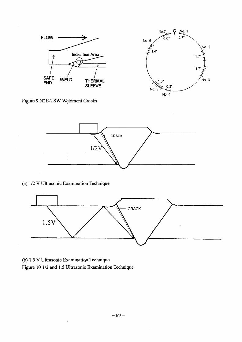
to-safe end weldments within the inservice inspection (ISI) program, are identified as N2A/B/C/D/E/F/G/H/J/K-TSW. During 1 991 outage (EOC-7) cracks were detected in four of these weldments (N2A/D/G/H-TSW) and conducted weld overlay repairs. In 1 992 outage (EOC-8), six cracks in weldnwnts N2E-TSW were discovered as shown in Figure 9, but a flawed pipe evaluation
~ 96 -
determined that this weldment was suitable for GOntinued operation without repair for at least one additional fuel Gycle. These Gracks in N2E-TSW were observed to grow (as list in Table 2) requinng a weld overlay repair in 1 993 outage (EOC-9). Thus, Iicensee decided to conduGt the weld overlay repair
for the weldments N2B/C/E/F/J/K-TSW. Table 2 provides a summary of all disGOVered flawed weldments during each refueling outage and the disposition of these flaws. ReGent the 1 2th refueling
outage (1997), four welds N2A-J4, N2C-J4. AD-J5 and AS-J7 of Loop A were still found IGSCC and overlay repairs were conducted. Up to now, only one indication at B S-J4 of RHR system which was identified as the GOunterbore signal was continuously inspected. All the overlay welds were inspected during each outage. There is no indication to find again.
The stress improvement technique IHSI considered in NUREG-03 1 3, Rev.2 has been applied to 75 welds in the reGirculation and RHR system in 1 984. Excluded 4 safe-end-to thennal sleeve welds with Inoonel 600 creviced design, there were 1 6 welds with IHSI to discover IGSCC.
The inspection was conduoted by the ultrasonic examination. The 1/2 V technique was used during the early stage of the in-service inspection. However, the weld surfaces often were concave due to the shrinkage and grinding. Thus the contact between the sensor and the surface was not fit well to reduce the possibility of the crack detection (see Figure I O(a)). The I .5V technique as shown in Figure lO(b) was used to extend the inspection scope and increase the reliability of the crack deteGtion.
FLAW EVALUATION When the cracks were discovered at the inspection weldments, the fracture evaluation based on the
NUREG-03 1 3 Rev. 2 and ASME Code Section XI must be performed to determine the repair works or not .
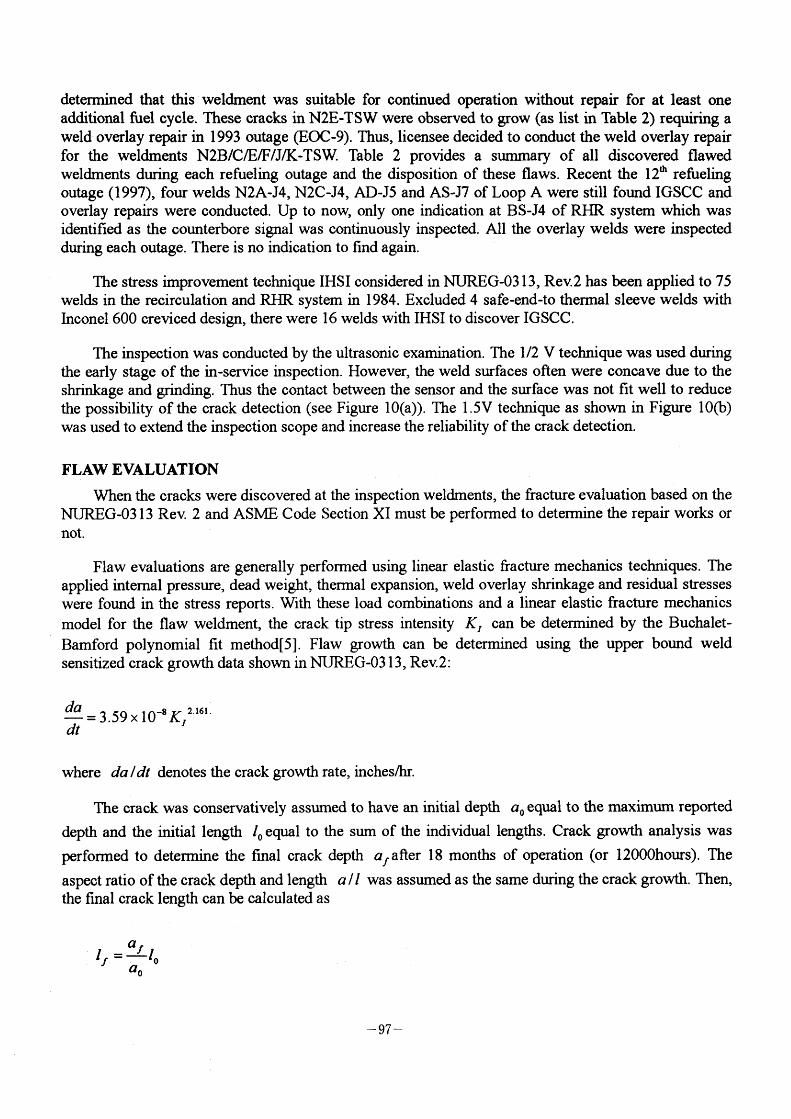
Flaw evaluations are generally performed using linear elastic fracture mechanios teohniques. The applied intemal pressure, dead weight, thermal expansion, weld overlay shrinkage and residual stresses were found in the stress reports. With these load combinations and a linear elastic fracture mechanics
model for the flaw weldment, the crack tip stress intensity KI can be detennined by the Buchalet-
Bamford polynomial fit method[5]. Flaw growth can be determined using the upper bound weld sensitized crack growih data shown in NUREG-03 1 3 . Rev.2:
da 2 161 dt = 3'59 x l0-8KI ' '
where da /dt denotes the craok growth rate, inches/br.
The crack was conservatively assumed to have an initial depth ao equal to the maximum reported
depth and the initial length lo equal to the sum of the individual lengths. Crack growth analysis was
performed to determine the final crack depth af after 1 8 months of operation (or 1 2000hours). The
aspect ratio of the crack depth and length a /1 was assumed as the same during the crack growth. Then,
the final crack length can be calculated as
If = af lo
ao
- 97 -
Then the allowable flaw size is determined using the criteria in ASME Section XI IWB-3640.
For the case of the inspection data of N2E-TSW as listed in Table 2, the input parameters were
expressed as
ao = 0.14", Io = 8. l" ao /lo = 57.85
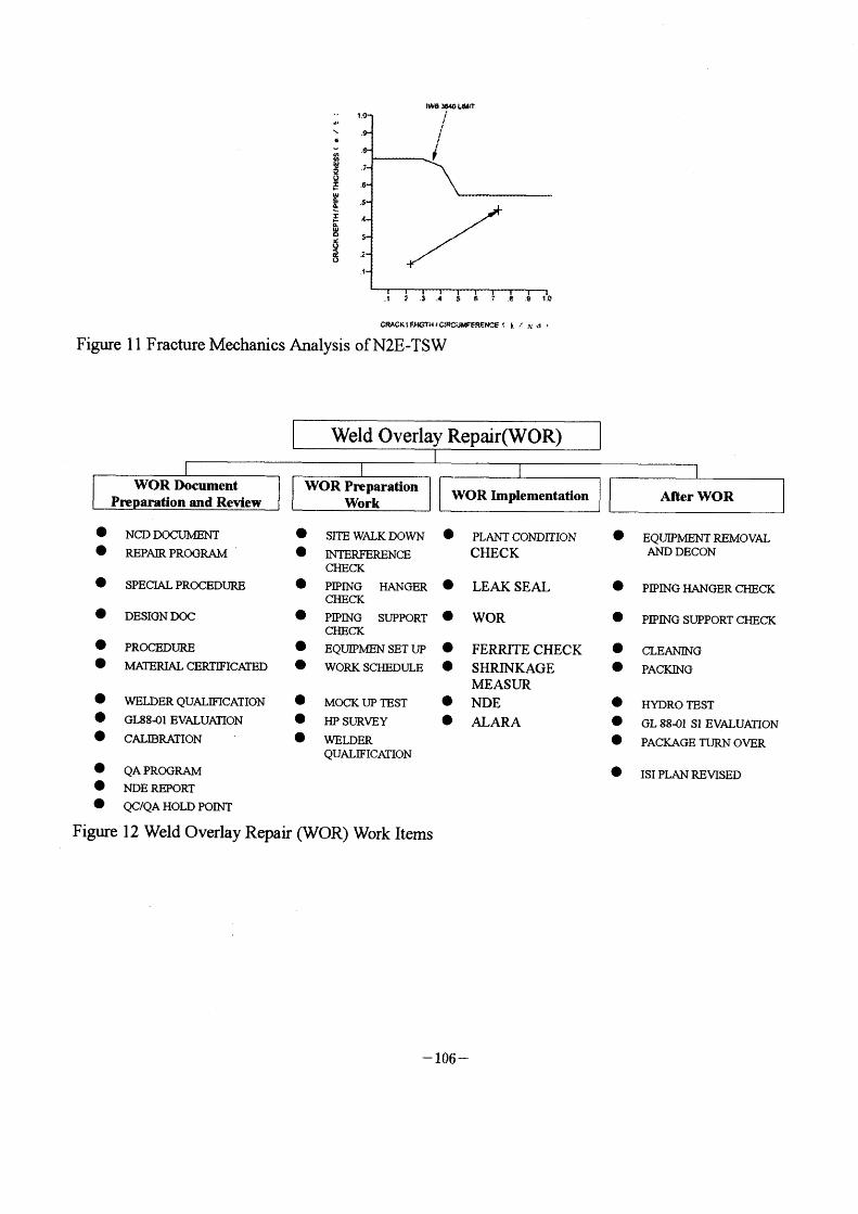
Using the crack growih analysis, the fmal crack depth af reached 0.475" after the assumption of
l 2000 hours operation. Then the fmal crack length lf was 27.5". Corresponding to the parameters in
IWB-3640, four parameters lo /rd, If /rd, ao /t and af /t were used to determine the allowable
crack size as shown in Figure I I . The orack size can be tolerate to operate at the next fuel cycle without
the repair. However, the significant growth of the fraoture weldrnent was observed during the next refueling outage as displayed in Table 2. Using the fracture analysis, the life prediGtion of the cracks was only 2000 hours. Thus, the repair work must be neGessary for the safe operation during the next fuel cycles.
Weld overlay induced shrinkage stresses were analyzed by ANSYS finite element computer program[6] . The actual weld overlay shrinkages measured after application of each weld overlay were equivalent as the thermal shrinkages at the nodes corresponding to repair welds. This approach is used to simulate the mechanical shrinkage observed in the field.
Ea~TI = 5
where I is overlay length, 6 is the as-built weld overlay shrinkage. E is Young's modulus and a is thermal expansion coefficient. The equivalent temperature drop AT will input at the nodes corresponding to repair welds .
WELD OVERLAY REPAIR Presently, there are 24 welds with weld overlay repairs. All these welds are m the reclfculation
system. The overlays were designed as " standard" overlays meeting the requirements of ASME Section XI IWB-3640 for overlay sizing. This repair program is to define the managerial and administrative eontrols for the implementation of Weld Overlay Repairs during outage which are covered the document preparation and review, preparation work, implementation and final reports. The detailed work items are listed as shown in Figure 1 2. The scope of work addressed by the repair program shall meet the requirements of ASME Section XI and Code Case 504-1 , In addition, the scope of work shall comply with the requirements of NUREG 03 1 3 Rev. 2 and Generic Letter 88-0 1 . All piping from the reactor pressure vessel to the frrst isolation valve was originally constructed in aceordanGe with the ASME SeGtion 111 identified in the piping system stress report. The design, welder, filler metal procurement, and welding repair shall be performed in accordance with ASME SeGtion XI. Nondestructive examination and testing work shall be performed in aooordance with ASME Section V and XI.
The standard overlay design considers the determinations of the thickness and the width. The net
section GOllapse criterion is used to calculate the minimum thickness [7]. 360" circumferential tbrough-wall~rack and safety factor 3 are assumed. The overlay thickness oan be GalGulated by the iterations of the following equations.
- 98 -
p = PT(1 -a/t - P~ Iaf )
2 - a/t
p = 2af (2 _a/t)sinp
;T
where af rs the material flow stress, a is the crack depth whioh equals to pipe wall thiGkness and t is
the overlay thickness. An iteration scheme is performed using these equations until the minimum required weld overlay thickness is determined.
The width of the overlay must consider the following conditions:
(1). The width is at least I .51!~
(2). InspeGtability
(3). Cover the crack extension (4). To minirnize possible damage to base material.
The effects of weld overlay on the sustained stress, global mass and global stiffaess were also evaluated after each outage repair based on the Generio Letter 88-0 1 with Supplement I .
CONCLUSION Reported fracture weldments information survey results show that IGSCC is probably the most
common aging degradation meehanism for Taiwan BWR-6 austenitie stainless steels piping. The strategy for controlling or mitigating IGSCC is necessary to manage in the future.
Due to the in-suffilcient of supply of the high quality Class I pipe components, the replacement of the fracture pipe is impractical in Taiwan. Therefore, the fracture analysis and the standard weld overlay
repair are the important contingent plant during each refueling outage. These evaluation and the repair
works can demonstrate that there is substantial margin for each of these cracked welds under conservative, bounding conditions to allow for continued operation for a minimum of one additional l 8month operation eycle. A complete procedures inoluding the inspeetion program, flaw evaluation, repair and quality control have been established in Taiwan to augrnent the safety of long-term nuclear
operation.
REFERENCE
l. United States Nuclear Regulatory Commission (USNRC) NUREG 0313, "Technical Report on Material Selection and Processing Guidelines for BWR Coolant Pressure Boundary Piping", Rev. 2,
publishing January 1 988.
2. United States Nuclear Regulatory Commission (USNRC) Generic Letter 88-0 1 , Subject: NRC Position on IGSCC in BWR Austenitic Steel Piping, dated January 25, 1 988, with Supplement I , dated February 4, 1992.
3. Taiwan Power Company, "Generic Letter 88-0 1 . Supplement I Weld Overlay Shrinkage Effect Assessment Report for Second Nuclear Power Station Unit 1 993 Outage, ZTP046 02 10 1 993
- 99 -
4. American Society of Mechanical Engineers (ASME) Boiler and Pressure Vessel Code Section XI, "Rules for Inservice Inspection ofNuclear Power Plant Components", 1 989 Edition.
5. Buchalet C.B. and Bamford W H "Stress Intensity Factor Solution for Contmuous Surface Flaws in Reactor Pressure Vessels", Mechonics ofCrack Growth, ASTM: STP 590, 1976.
6. Desalvo G. and Gormin, User Information Manual and Theoretica/ Manual. ANSYS Engineering System, 1 991 .
7. Smith E. ,"Theoretical Justification ofthe Association ofa Critical Net-Section Stress with Fracture Initiation at a Crack Tip", International Journal of Pressure Vessels and Piping, Vol. 8, 1 980, pp. 303-3 1 1 .
- 100 -
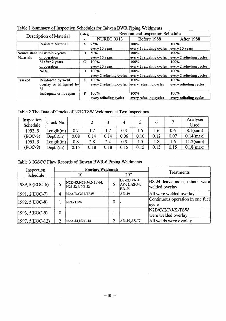
Table 2 The Data of Cracks of N2E-TSW Weldment at Two Inspections
Table 3 IGSCC Flaw Records of Taiwan BWR-6 Piping Weldments
- 101 -
N18
A,n J~Ja~n
ALn
~ ~ '~"\\\~\~lll~
/ A ~'
a /(~:1 a~//
~L~~:~l~D
l' ,4
A,,J, \
~:~~/"
~
h~~('~i' /
~~f l' N28
~
Li~!
N ~a:r~t Jl ,?;/ I14
~'~(~;i/ 'L~tl2J:nttvl~;
~l
"~!!t
l
~~~ ./~~~ 'OdPA
A.n I '\bu2 AulO ~~
dhS2A (':~CU) l--;-/7rl~'~..~ ~_ _ _1/i7 \ .~- -:i'n
n~B~ J~ b\ ~'r
ANt ADn
a~B
AWll
n A~
A~'IO JL
JUhB
A•Ji ~!
S~~N ~A A~J-
ADJC
Ab.,,
I
ADd' ADn
Figure. I Loop A welds[3]
Figure 2 weldments in Loop B
- 102 -
(~~GtND ,~r t~
SQ9b~d C~~ ~O ~8~CLFI~
W~ P~tll ~itda• ~O_ J1 V~U (~8N sbeO GWW 8U1 'QW~U
'~'ttl82
' ~;:
Figure 3 . Nl Nozzle and Safe-end Weldments
edb E,~' ~•"g~!9 ~~CL RI, o~•' a8t•e,
,~r Notd-(SASNGtlO
Figure 4. N2 Nozzle and Safe-end Weldrnents
~r NQd-
8db E,• ~•Q't ~~CL8bl)F~ Cb~,• G8lec,
,8~CLN,
Figure 5 N4 Nozzle Weldments
- 103 -
RPV b~ ,SA8NGL,O
Th~d a-- Ednbl aold 88leQ
T~~ef~i h-~,- ~,,~ ~A~a.Fe,
Figure 6. N5 Nozzle Weldrnents
8~ E~l a~•, 8ilee) bQ,.' Ie2
RPV Nordo (sA~eGtn)
8u.c
J1 W~ ,cCw•U (C•tn s,•eO OruJ ul~) ,aw~ a,u•' ~tn,
'~'ff;B'
~,,',, /\ \ (a'lc'taRrg~O 5d.E,eE'al~'
(~Go a. O 11•md Slw• ExD•ao (S~e ct Fa] T~~ S~-(StJd- ~!•D
(t~" 88le6,
Figure 7. N6 Nozzle Weldments
WELD OVERLAY
\ PIPE /
WAL L
f , ., i
~ ar S_
\ BUTT WELD
Figure 8 standard Weld Overlay
- 104 -
N0.7 No. 1
FLOW No 6 O 6" o. 7"
No. 2 1 .411
Indication Area 1 7,l
1 .711
SAFE WELD END THERMAL
SLEEVE No. 5
1 .5"
0.3,,
No 4
No. 3
Figure 9 N2E-TSW Weldment Cracks
CRACK
l 12
(a) I /2 V Ultrasonic Examination Technique
CRACK
l .5V
(b) I . 5 V Ultrasonic Examination Technique
Figure I O I /2 and I .5 Ultrasonic Examination Technique
- 105 -
IO
\
(,) 6 IJ) $1i'
~
~ •6 ~ _5 ,}~r
!: 4 ,-a ~ e ~e " ~ 2
1 f
'wa eao Ldd'T
f
/
i '3 '4 s G P' 'e 1'c
cRAcF~lF'wcTHla"ciJ"FFRE'Nc'E t L "~' d '
Figure I I Fracture Mechanios Analysis ofN2E-TSW
e NCD DOCUMENT e SITE WALK DOWN O pLANT CONDrrloN O O REPAIR PROGRAM ' e INTERFERENCE CHECK
CHECK O SPECIAL PROCEDURE e plplNG HANGER e LEAK SEAL
CHECK e DESIGN Doc e plpING SUPPORT O WOR
CHECK e pROCEDUIU3 O EQUIPMEN SET UP O FERRJTE CHECK e MA113RIAL CERTIFICArl3D e WORK SCHEDULE O SHRINKAGE
MEASUR e waLDER QUALIFICATION e MOCK UP TE ST e N DE
e GL88~1 EVALUAIION e ALARA e HP SURVEY e CALn3RArION ' e WELDER
QUALIFICATION O QA PROORAM O NDE REPORT e QC/QA HOLD POn~T
Figure 1 2 Weld Overlay Repair (WOR) Work Items
e
o
o e
o e e
e
EQUD?MENT REMO VAL AND DECON
PIPlNG HANGER CHECK
PIPING SUPPORT CHECK
CLEANING PAClaNG
HYDRO TEST GL 88~)1 Sl EVALUAnoN
PACKAGE TUl~~1 OVER
ISI PLAN RBVISED
- 106 -
lll-2 ISI NDE in Korean Nuclear Power Plants Yi-Hwan (Peter) Jeong, Korea Electric Power Research
Institute, Korea
ISI NDE in KOrean NuClear POWer Plants
Yi-Hwan (Peter) Jeong
Hee-Jong Lee
Yong-Sik Kim Materials & Corrosion Laboratory
Korea Electric Power Research Institute
Taej on, Korea
Abstract
Structural integrity of nuclear components is important for a safe
operation of nuclear power plants. Therefore, the structural integrity
should always be maintained by reliable, periodic inservice inspections.
Korea Electric Power Company(KEPCO) operates the entire Korean nuclear power plants. Since the safe operation and the inservice inspection(ISD of the nuclear power plants are under the plant owner's
responsibility, Korea Electric Power Research Institute(KE;PRD, the R&D
division of KEPCO, has established an integrated ISI NDE support system(called, ISI NDE Total Support System: TSS), primarily focused on
the inservice inspection of nuclear power plants. And the KEPRI has
initiated a long -term plan for the development of key ISI NDE technology
that is necessary for an efficient on-site support. This paper describes
the KEPRI's TSS and the long-terrn plan for the key ISI NDE technology development.
Introduction
Since Kori Unit I , the first nuclear power plant in Korea, started
to generate electricity in 1978, Korea has built twelve nuclear power
plants and produces lOgigaWatts of electricity (25~ of the total electricity
- 107 -
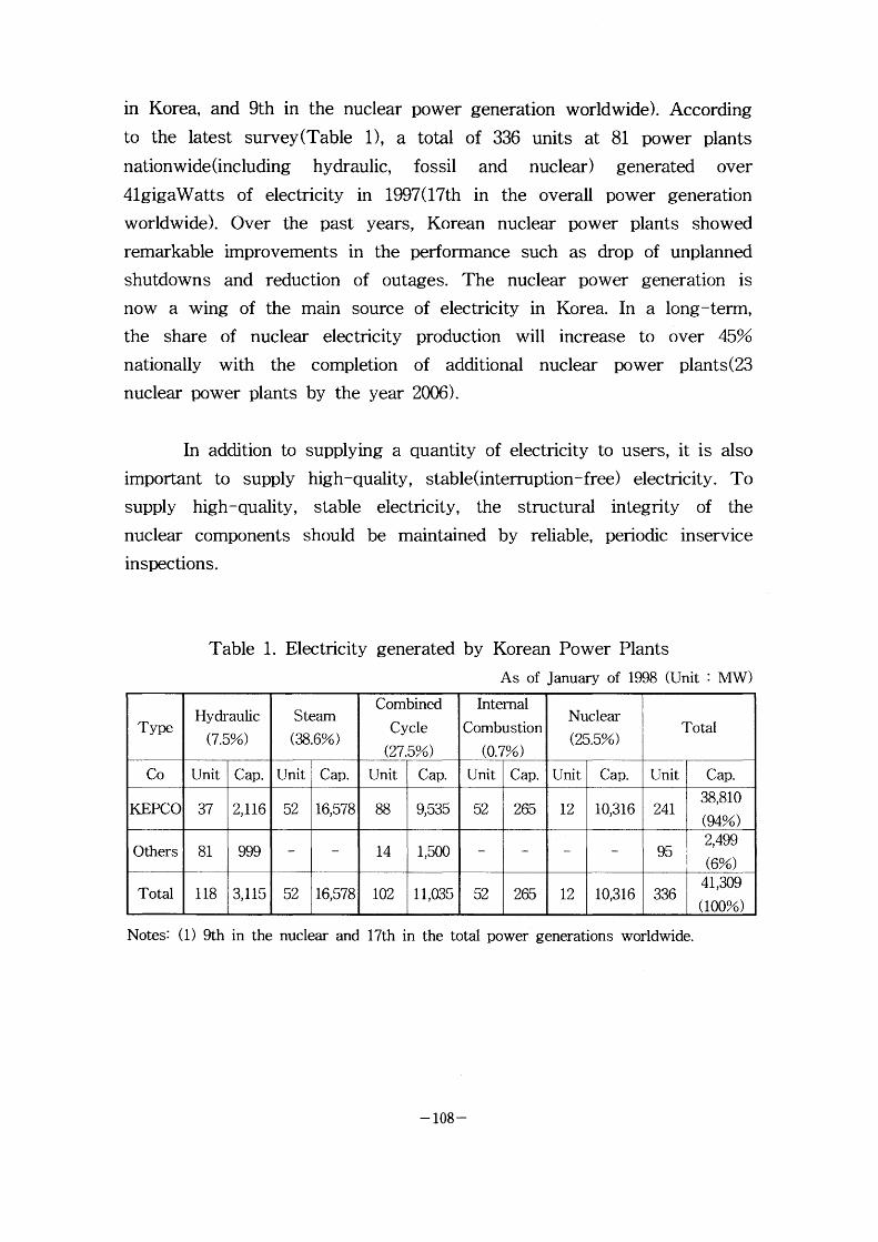
in Korea, and 9th in the nuclear power generation worldwide). According
to the latest survey (Table I ), a total of 336 units at 81 power plants
nationwide (including hydraulic, f ossil and nuclear) generated over
4lgigaWatts of electricity in 1997(17th in the overall power generation
worldwide). Over the past years, Korean nuclear power plants showed
remarkable improvements in the perforrnance such as drop of unplanned
shutdowns and reduction of outages. The nuclear power generation is
now a wing of the main source of electricity in Korea. In a long-term,
the share of nuclear electricity production will increase to over 45%
nationally with the completion of additional nuclear power plants(23
nuclear power plants by the year 2006).
In addition to
important to supply
supply high-quality,
nuclear components inspections.
supplying a quantity of electricity to users, it is also
high-quality, stable(interruption-free) electricity. To
stable electricity, the structural integrity of the
should be maintained by reliable, periodic inservice
Tab le 1 . Electricity generated by Korean Power Plants
As of January of 1998 (Unit MW )
Notes: (1) 9th in the nuclear and 17th in the total power generations worldwide.
- 108 -
PSI/ISI
During the plant operation, plant components are under severe
environmental conditions such as high temperature, high pressure, corrosion, mechanical stress and vibration. Therefore, various types of
inservice defects or premature failures can occur in the plant components.
Such structural failures can cause catastrophic accident. In particular, the
component failures in the primary system in the nuclear power plant can
cause serious damages to the properties and human lives by radiation
exposure. Therefore, periodic inservice inspections should be conducted
during the plant operation in order to maintain the structural integrity of
nuclear components.
Plant component inspections are classified as preservice inspection(PSD and inservice inspection(ISD depending upon whether the
inspection is perforrned at the completion of plant construction or during
the plant operation. The PSI is perforrned to confinn that all structural
members of the plant have been constructed safely and properly, and also
to acquire initial inspection data that can be compared with the future
inservice inspection results. The ISI of nuclear components is generally
perfonned in 10-year period during the plant operation. The PSI and ISI
in Korean nuclear power plants are perforrned according to ASME code
Section XI: "Rules for Inservice Inspection of Nuclear Power Plant
Components" Because the ASME code mandates that PSVISI be perforrned by nondestructive exarnination(NDE), the NDE for nuclear
component examination is particularly important.
Status of ISI NDE
During the last several decades, the nondestructive evaluation(NDE) technology for inservice inspection(ISD in nuclear power
plant has been greatly improved. Particularly, with the advancement of
computer technology in recent years, the NDE equipment for reactor pressure vessel(RPV), steam generator(SG), turbine, pressurizer, reactor
- 109 -

coolant pump(RCP) and pipings were fully 2lutomated and sophisticated.
Consequently, the ilccuracy, the speed and the reliability of the ISl
perforrn~mce \vere impro\'ed accordingly.
Ilo\\'e\'er, the KEPCO has been he'avily relying on foreign
countries in conduc ting the inservice inspections of the nuclear components due to lack of key ISI NDE technology. Consequently, the ISl
operation costs KEPCO a great deal of financial burden. Furthermore, due
to lack of the key ISI NDE technology, the KEPCO has not been able to
respond to site problems in an efficient and timely manner. Such difficulties of Korean nuclear power plants provided the needed impetus
for KEPCO to develop a long-term plan for the ISI NDE technology development and to prepare for the independent operation of inservice
inspection of nuclear power plant components.
ISI NDE Long-Term Plan
The KE;PCO, as a utility, is primarily responsible for the safe and
reliable operation of the nuclear power plants. Therefore, the KEPCO
monitors the periodic inspections of nuclear components performed by
domestic and foreign companies. The mission of KEPRI, the R&D division of KEPCO, is to perform the research and development of ISI
N~DE technology as well as the associated technology transfer. To meet
such mission, the KEPRI has established an on-site support system,
called ISI NDE total support system(TSS), that can respond to various
plant ISI problems in an efficient and timely manner. Furthermore, in
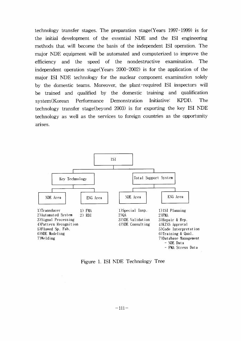
order to successfully support the plant ISI operation, the KEPRI has
established a long-term plan for the development of key ISI NDE technology(Figure I ). The key ISI NDE technology areas were chosen
among the most important technical areas in conducting the on-site ISI
support tasks.
The TSS and the key IS'I NDE technology development programs contain the following three stages: preparation, independent operation, and
- I Io -
technology transfer stages. The preparation stage(Years 1997-1999) is for
the initial development of the essential NDE and the ISI engineering
methods that will become the basis of the independent ISI operation. The
major NDE equipment will be automated and computerized to improve the
efficiency and the speed of the nondestructive examination. The independent operation stage(Years 2000-2002) is for the application of the
major ISI NDE technology for the nuclear component examination solely
by the domestic teams. Moreover, the plant-required ISI inspectors will
be trained and qualified by the domestic training and qualification
system ( Korean Perforrnance Demonstration Initiative: KPDD. The technology transfer stage(beyond 2003) is for exporting the key ISI NDE
technology as well as the services to foreign countries as the opportunity
arises.
ISI
Kev. Techno I ogy
NDE Area
1)Transducer 2)Automated System 3)Signal Processing 4)Pat tern Recognit ion 5)Flawed Sp. Fab. ONDE Model ing 7 )We I d i ng
Tot a l Suppor t
EN 'G Area
1) FMA 2) RBI
S~. ,s t em
Figure
\.'DE Area
1)Special Insp. _9)QA
3)\'DE Val idat ion 4)NDE Consul t ing
1. ISI NDE Technology
E\G Area
1)ISI Plauning _? ) FMA
3)Repair & Rep. ~)KINS Appro\~a l 5)C.ode Interpretat ion 6)Training & Qual . 7)Dat abase \.fanagement
- \.'DE Data
- F~A Stress Data
Tree
-111-
ISI NDE Total Su pport System
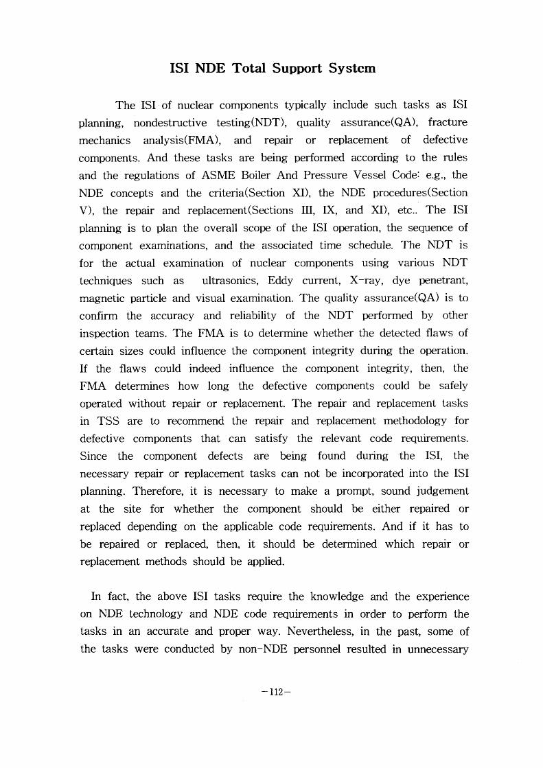
The ISI of nuclear components typically include such tasks as ISI
planning, nondestructive testing(NDT), quality assurance(QA), fracture
mechanics analysis(FMA), and repair or replacement of defective components. And these tasks are being perfonned according to the rules
and the regulations of ASME Boiler And Pressure Vessel Code: e.g., the
NDE concepts and the criteria(Section XD, the NDE procedures(Section
V), the repair and replacement(Sections 111, IX, and XD, etc.. The ISI
planning is to plan the overall scope of the ISI operation, the sequence of
component examinations, and the associated time schedule. The NDT is
for the actual examination of nuclear components using various NDT
techniques such as ultrasonics, Eddy current, X-ray, dye penetrant, magnetic particle and visual examination. The quality assurance(QA) is to
confirm the accuracy and reliability of the NDT performed by other
inspection tearns. The FMA is to determine whether the detected flaws of
certain sizes could influence the component integrity during the operation.
If the flaws could indeed influence the component integrity, then, the
FMA determines how long the defective components could be safely operated without repair or replacement. The repair and replacement tasks
in TSS are to recommend the repair and replacement methodology for
defective components that can satisfy the relevant code requirements.
Since the component defects are being found during the ISI, the necessary repair or replacement tasks can not be incorporated into the ISI
planning. Therefore, it is necessary to make a prompt, sound judgement
at the site for whether the component should be either repaired or
replaced depending on the applicable code requirements. And if it has to
be repaired or replaced, then, it should be determined which repair or
replacement methods should be applied.
In fact,
on NDE tasks in
the tasks
the above ISI tasks require the knowledge and
technology and NDE code requirements in order
an accurate and proper way. Nevertheless, in the
were conducted by non-NDE personnel resulted
the experience
to perform the
past, some of
m unnecessary
- I12 -
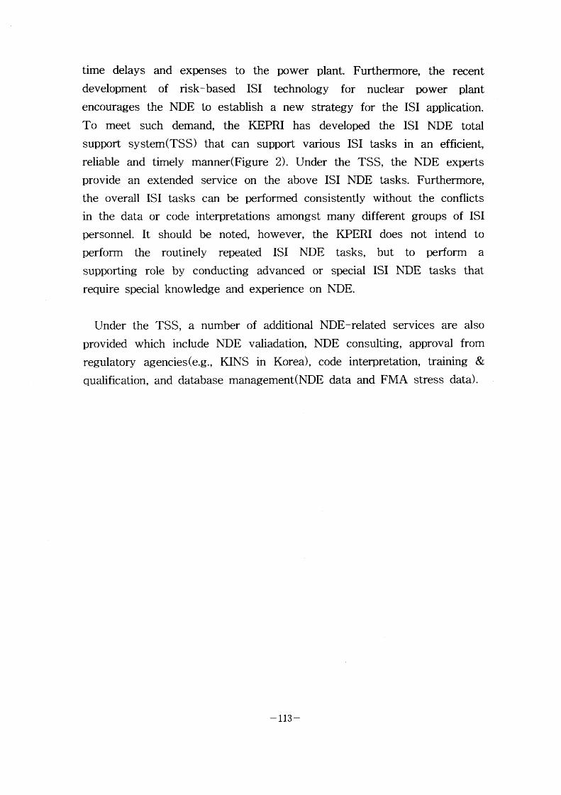
time delays and expenses to the power plant. Furtherrnore, the recent
development of risk-based ISI technology for nuclear power plant encourages the NDE to establish a new strategy for the ISI application.
To meet such demand, the KEPRI has developed the ISI NDE total support system(TSS) that can support various ISI tasks in an efficient,
reliable and timely manner(Figure 2). Under the TSS, the NDE experts
provide an extended service on the above ISI NDE tasks. Furthermore,
the overall ISI tasks can be performed consistently without the conflicts
in the data or code interpretations amongst many different groups of ISI
personnel. It should be noted, however, the KPERI does not intend to
perform the routinely repeated ISI NDE tasks, but to perform a supporting role by conducting advanced or special ISI NDE tasks that
require special knowledge and experience on NDE.
Under the TSS, a number of additional NDE-related services are also
provided which include NDE valiadation, NDE consulting, approval from
regulatory agencies(e.g., KINS in Korea), code interpretation, training &
qualification, and database management(NDE data and FMA stress data) .
-113-
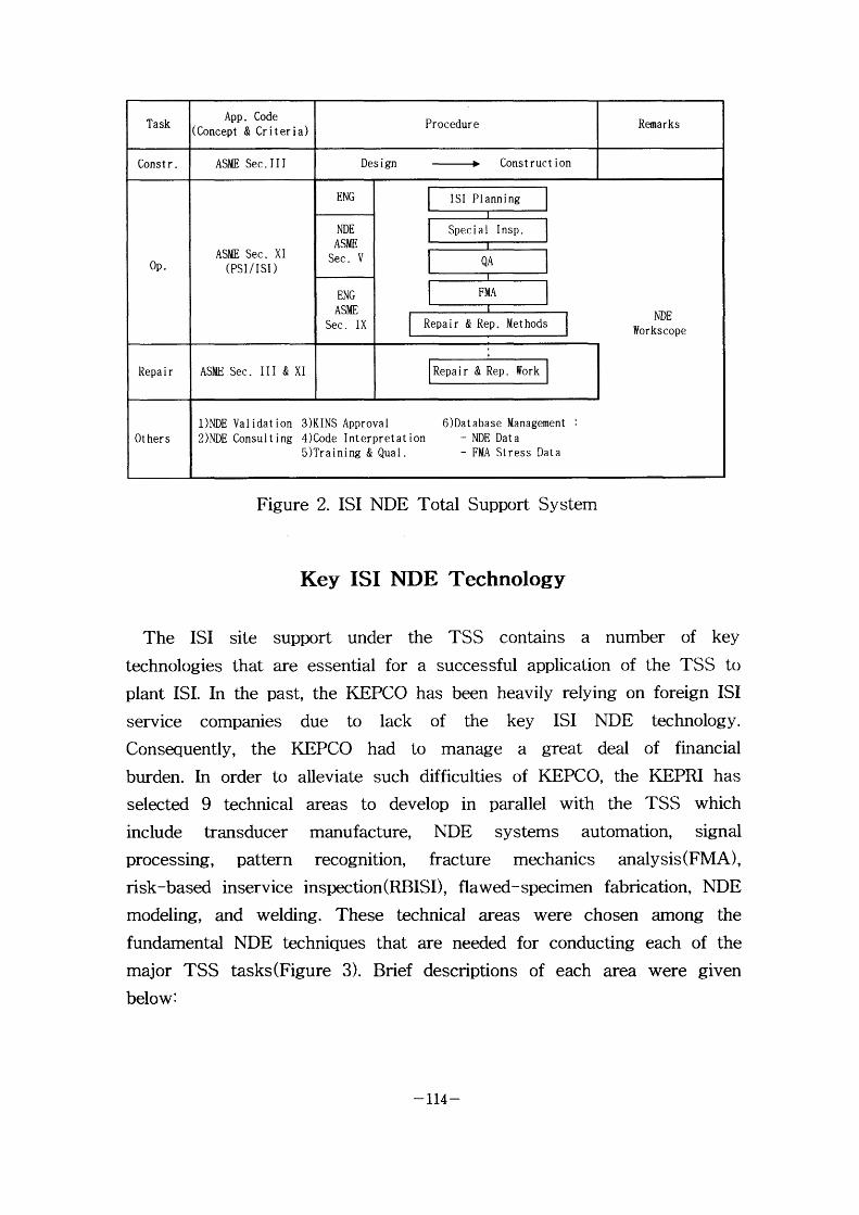
Figure 2. ISI NDE Total Support System
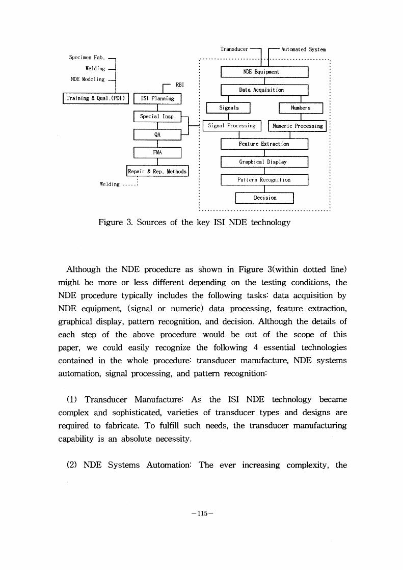
Key ISI NDE Technology
The ISI site support under the TSS contains a number of key technologies that are essential for a successful application of the TSS to
plant ISI. In the past, the KEPCO has been heavily relying on foreign ISI
service companies due to lack of the key ISI NDE technology. Consequently, the KEPCO had to manage a great deal of financial burden. In order to alleviate such difficulties of KEPCO, the KEPRI has
selected 9 technical areas to develop in parallel with the TSS which
include transducer manufacture, NDE systems automation, signal processing, pattern recognition, fracture mechanics analysis(FMA),
risk-based inservice inspection(RBISD, flawed-specimen fabrication, NDE
modeling, and welding. These technical areas were chosen among the
fundarnental NDE techniques that are needed for conducting each of the
major TSS tasks(Figure 3). Brief descriptions of each area were given
below :
-H4-
Specimen Fab.
Welding
NDE Model i ng
Training & Qual .(PDI)
Weldlng - - - -
Figure 3. Sources of the key IS I NDE technology
Although the NDE procedure as shown in Figure 3(within dotted line)
might be more or less different depending on the testing conditions, the
NDE procedure typically includes the following tasks: data acquisition by
NDE equipment, (signal or numeric) data processing, feature extraction,
graphical display, pattern recognition, and decision. Although the details of
each step of the above procedure would be out of the scope of this paper, we could easily recognize the following 4 essential technologies
contained in the whole procedure: transducer manufacture, NDE systems
automation, signal processing, and pattern recognition:
(1) Transducer Manufacture: As the ISI NDE technology became complex and sophisticated, varieties of transducer types and designs are
required to fabricate. To fulfill such needs, the transducer manufacturing
capability is an absolute necessity.
(2) NDE Systems Automation: The ever increasing complexlty the
- 115 -
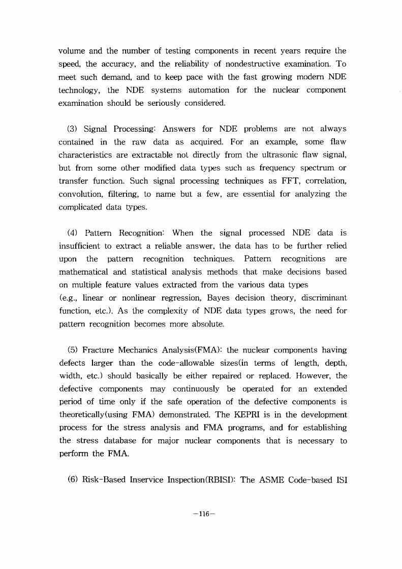
volume and the number of testing components in recent years require the
speed, the accuracy, and the reliability. of nondestructive examination. To
meet such demand, and to keep pace with the fast growing modern NDE
technology, the NDE systems automation for the nuclear component examination should be seriously considered.
(3) Signal Processing: Answers for NDE problems are not always
contained in the raw data as acquired. For an example, some flaw characteristics are extractable not directly from the ultrasonic flaw signal,
but from some other modified data types such as frequency spectrum or
transfer function. Such signal processing techniques as FFT, correlation,
convolution, filtering, to name but a few, are essential for analyzing the
complicated data types.
(4) Pattern Recognition: When the signal processed NDE data is insufficient to extract a reliable answer, the data has to be further relied
upon the pattern recognition techniques. Pattern rec ognitions are
mathematical and statistical analysis methods that make decisions based
on multiple feature values extracted from the various data types
(e.g., Iinear or nonlinear regression. Bayes decision theory, discriminant
function, etc.). As the complexity of NDE data types grows, the need for
pattern recognition becomes more absolute.
(5) Fracture Mechanics Analysis(FMA): the nuclear components having
defects larger than the code-allowable sizes(in terms of length, depth,
width, etc.) should basically be either repaired or replaced. However, the
defective components may continuously be operated for an extended period of time only if the safe operation of the defective components is
theoretically(using FMA) demonstrated. The KE;PRI is in the development
process for the stress analysis and FMA programs, and for establishing
the stress database for major nuclear components that is necessary to
perforrn the FMA.
(6) Risk-Based Inservice Inspection(RBISD: The ASME Code-based ISI
-H6-
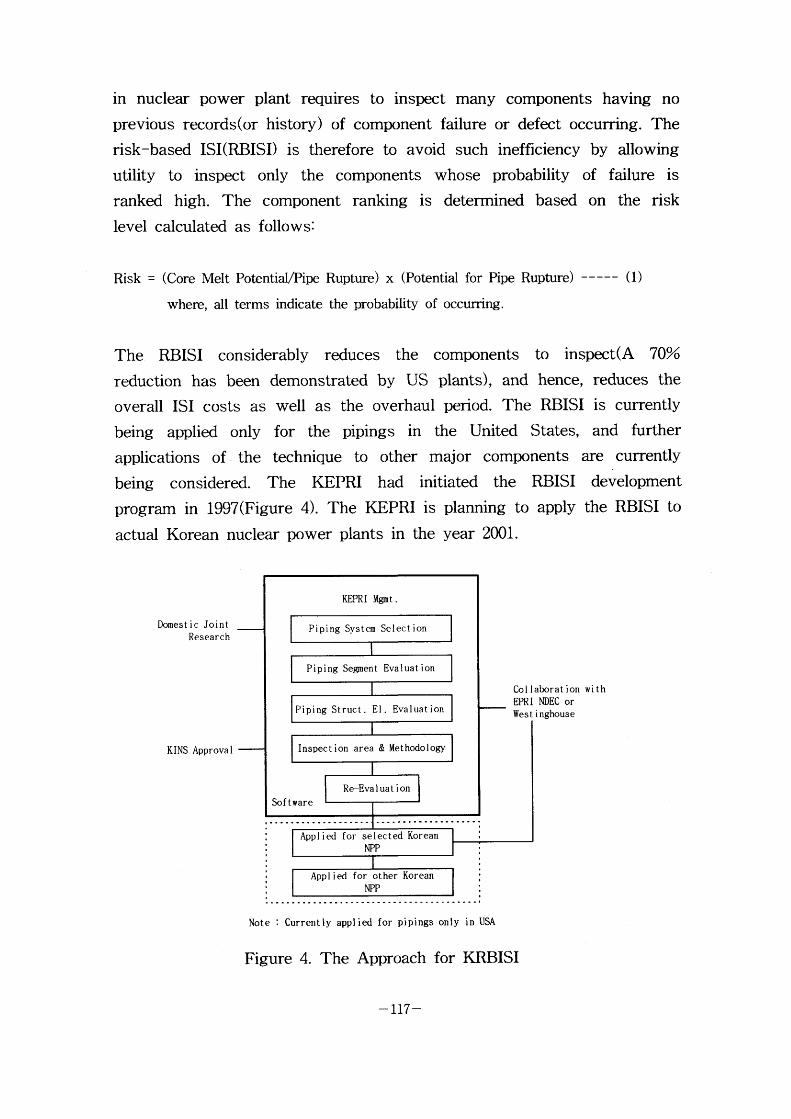
in nuclear power plant requires to inspect many components having no previous records(or history) of component failure or defect occurring. The
risk-based ISI(RBISD is therefore to avoid such inefficiency by allowing
utility to inspect only the components whose probability of failure is
ranked high. The component ranking is detennined based on the risk level calculated as follows:
Risk = (Core Melt PotentiaVPipe Rupture) x (Potential for Pipe Rupture) ----- (1)
where, all t.erms indicate the probability of occurring .
The RBISI considerably reduces the components to inspect(A 70~ reduction has been demonstrated by US plants), and hence, reduces the
overall ISI costs as well as the overhaul period. The RBISI is currently
being applied only for the piping s in the United States, and further
applications of the technique to other major components are currently
being considered. The KEPRI had initiated the RBISI development prograrn in 1997(Figure 4). The KEPRI is planning to apply the RBISI to
actual Korean nuclear power plants in the year 2001.
Domest ic Joint Research
KlNS Approval
Col laborat ion wi th
NDEC or Wes t i nghouse
Note : Currently applied for pipings only in USA
Figure 4. The ApprOach fOr KRBISI
-117-
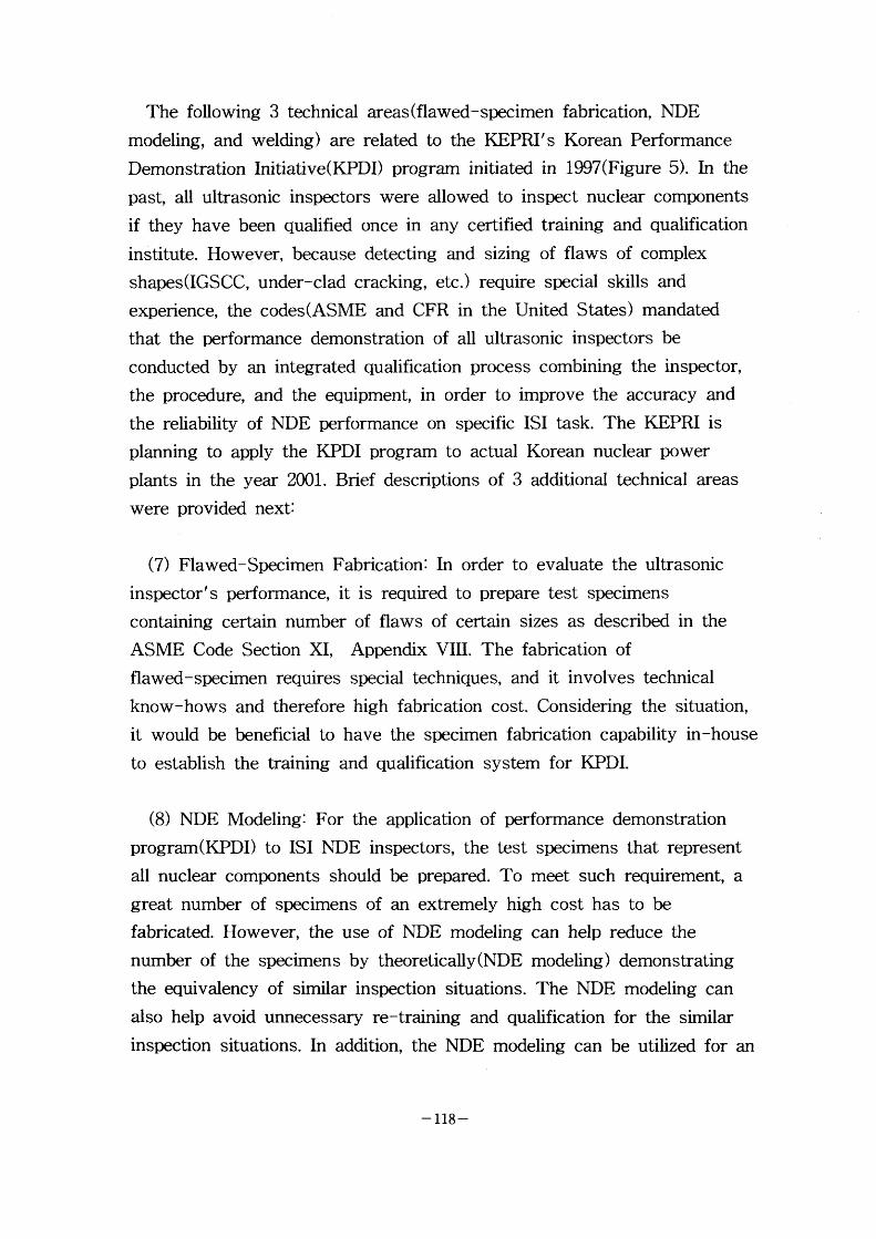
The following 3 technical areas (flawed-specimen fabrication, NDE
modeling, and welding) are related to the KEPRI's Korean Performance
Demonstration Initiative(KPDD program initiated in 1997(Figure 5). In the
past, all ultrasonic inspectors were allowed to inspect nuclear components
if they have been qualified once in any certified training and qualification
institute. However, because detecting and sizing of flaws of complex
shapes(IGSCC, under-clad cracking, etc.) require special skills and
experience, the codes(ASME and CFR in the United States) mandated
that the performance demonstration of all ultrasonic inspectors be
conducted by an integrated qualification process combining the inspector,
the procedure, and the equipment, in order to improve the accuracy and
the reliability of NDE performance on specific ISI task. The KEPRI is
planning to apply the KPDI program to actual Korean nuclear power
plants in the year 2001. Brief descriptions of 3 additional technical areas
were provided next:
(7) Flawed-Specimen Fabrication: In order to evaluate the ultrasonic
inspector's performance, it is required to prepare test specimens
containing certain number of flaws of certain sizes as described in the
ASME Code Section XI, Appendix VIII. The fabrication of
flawed-specimen requires special techniques, and it involves technical
know-hows and therefore high fabrication cost. Considering the situation,
it would be beneficial to have the specimen fabrication capability in-house
to establish the training and qualification system for KPDI.
(8) NDE Modeling: For the application of performance demonstration
program(KPDD to ISI NDE inspectors, the test specimens that represent
all nuclear components should be prepared. To meet such requirement, a
great number of specimens of an extremely high cost has to be
fabricated. However, the use of NDE modeling can help reduce the
number of the specimens by theoretically(NDE modeling) demonstrating
the equivalency of similar inspection situations. The NDE modeling can
also help avoid unnecessary re-training and qualification for the similar
inspection situations. In addition, the NDE modeling can be utilized for an
- I18 -
effective education for the theoretical wave propagation
(9) Welding: The welding techniques are continuously needed to
fabricate the test specimens for the inspector's performance demonstration
and to develop optimum repair and replacement technology for defective
com ponents.
col laborat lon wi th col laborat ion with European Spec imen EPRI NDEC Manutacturer Fabr i cat ion ( Iowa state Univ. for
Mode I i ng)
KINS Approval
col laborat ion with Foreign Ut i I ity
Note : currentfy applied for pipings, RPv, and studs & Bolts in USA.
Figure 5. The Approach for KPDI
Summary
Structural integrity of nuclear components is important for a safe
operation of nuclear power plant. Therefore, the structural integrity should
always be maintained by reliable, periodic inservice inspections. Since the
safe operation and the inservice inspection of the nuclear power plants
are under the plant owner's responsibility, KEPRI, the R&D division of
KE;PCO, has established an integrated ISI NDE total support system(TSS), primarily focused on the inservice inspection of nuclear
-119-
power plants. And the KEPRI has initiated a long-tenn plan for the
development of key ISI NDE technology that is necessary for an efficient
on-site support. Although KEPRI took the lead in this effort to establish
the TSS, the KEPRI intends to collaborate with industry, universities, and
research institutes throughout the development process in order to
promote the entire Korean ISI NDE technology.
Ref erences
1 . Plant Operatron Statistics Korea Electnc Power Company 1997
- 120 -
III-3 Core Shroud Replacement of Fukushima-Daiichi Unit #3
Jun Matsumoto, Nuclear Power Plant Management Dept.
Tokyo Electric Power Company, Japan
Core Shroud Replacement of Fnkushima-Daiichi Unit #3
J. MATSUMOTO Tokyo Electric Power Company
l - I -3 Uchisaiwai-cho, Chiyoda-ku Tokyo, Japan
Abstract
The core shroud replacement of a Boiling Water Reactor (B WR) is now
in progress at Fukushima-Daiichi Unit # 3(1F3) of the Tolyo Electric
Power Company (TEPCO) in Japan. The core shroud and other core
interna/ components made of type 304 stainless stee/ (SS) are replaced
with the ones made of low carbon ope 316L SS to improve Intergranular
Stress Corrosion Cracking (IGSCC) resistance. This project is the first
application of the replacement procedure developed for the welded core
shroud, and employs various advanced technologies. The outline of the
core shroud replacement project and applied technologies are discussed in
this paper.
1. Introduction
Since the core shroud cracking was found, the Japanese BWR owners and the plant
manufacturers have conducted several R&D programs to establish the countermeasures
for core shroud cracking. These countermeasures are repair and mitigation
technologies including replacement, bracket reinforcement, tie rod reinforcement,
hydrogen water chemistry (HWC), water jet peening, shot peening, and noble metal
technologies. When the crack was found in Fukushima-Daiichi Unit #2 ( IF2), the core
shroud was reinforced by the brackets which had been studied as one of the repair
concepts.
The countermeasures for the actual plants should be carefully selected considering
effect and applicability of the countermeasures, uncertainty of the developed
technologies, estimated cost (tool fabrication and implementation cost, inspection cost
through the plant life etc.), estimated schedule, possibility of cracking, political
- 121 -
environment, and so on. Based on the evaluation ofthese influential elements, TEPCO
decided to replace the core shrouds made of 304SS which has relatively higher potential
ofIGSCC. Among 1 7 BWR plants owned by TEPCO, four plants have the core
shrouds made of 304SS. In accordance with the long term outage schedule, I F3 was
selected as the first plant to replace the core shroud with the one made of 3 1 6L SS which
has much less potential of IGSCC.
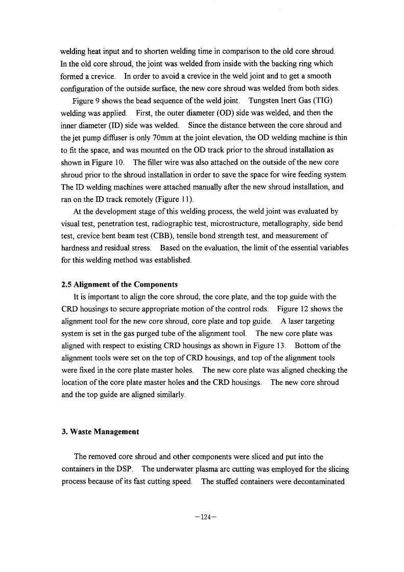
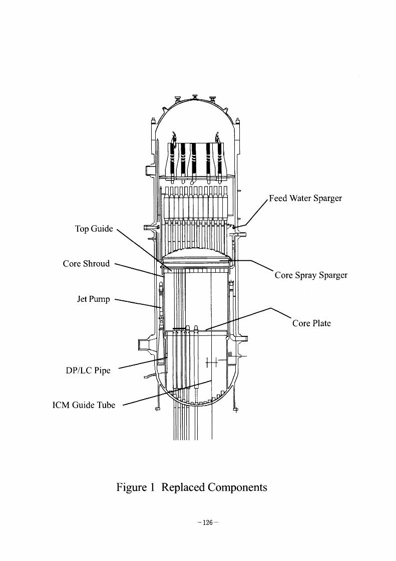
In addition to the core shroud, the majority of the internal components made of 304SS
are replaced in the IF3 project. Those are (1) core shroud, (2) top guide, (3) core plate,
(4) core spray spargers, (5) feed water spargers, (6) jet pumps, (7) DP/LC pipe, (8) ICM
guide tubes, and internal pipes and nozzle safe ends connected to these components as
shown in Figure I . Prior to the application to IF3, integrity and reliability of the
replacement process were demonstrated by the full scale mock-up test, which was
conducted by the Nuclear Power Engineering Corporation (NUPEC).
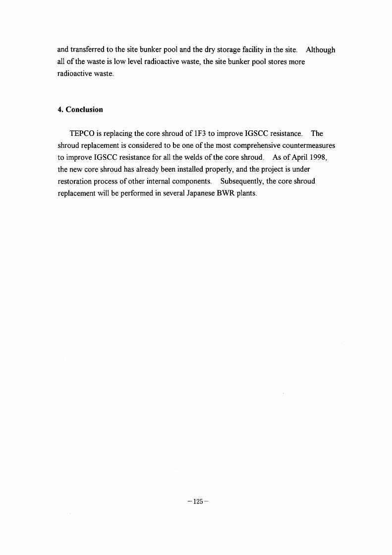
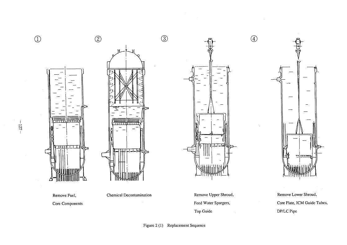
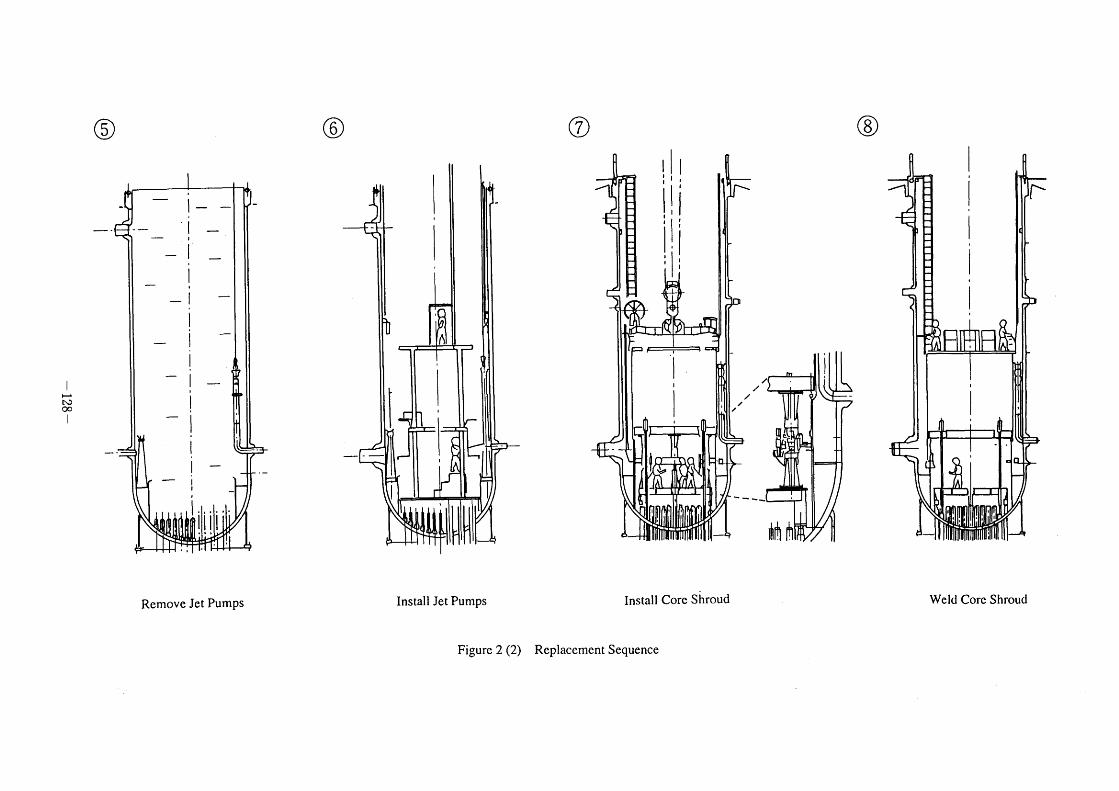
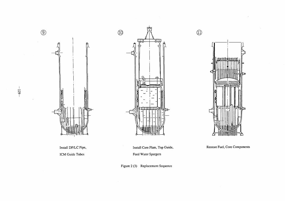
2. Replacement Process
The replacement sequence is shown in Figure 2. Afier the removal of all fuels and
detachable components, inside of the pressure vessel and the remaining internal
components were chemically decontaminated. Subsequently, most ofthe removals are
conducted by means ofElectrical Discharge Machining (EDM) process under water.
Following the removal of all components to be replaced, the new components were
installed in reverse order ofthe removal. Most of the installation process including
welding was performed in a dry condition to acquire high quality of the weld. The
followings are the major technologies applied to the core shroud replacement process.
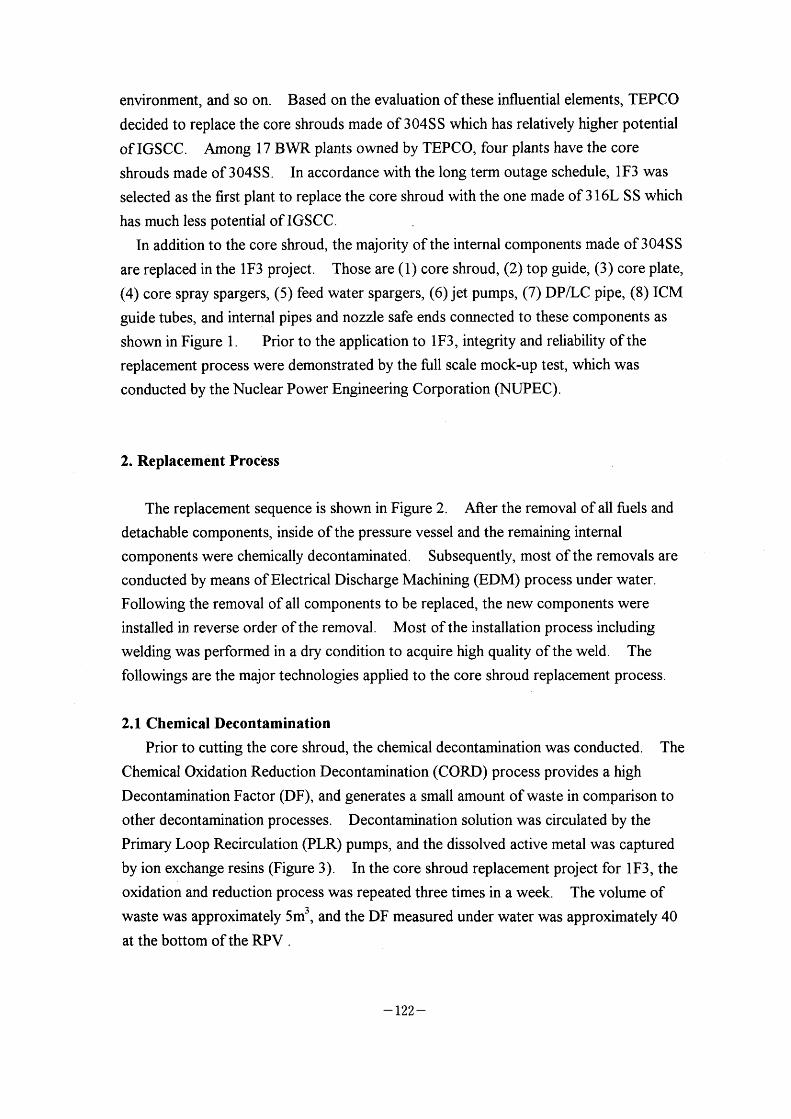
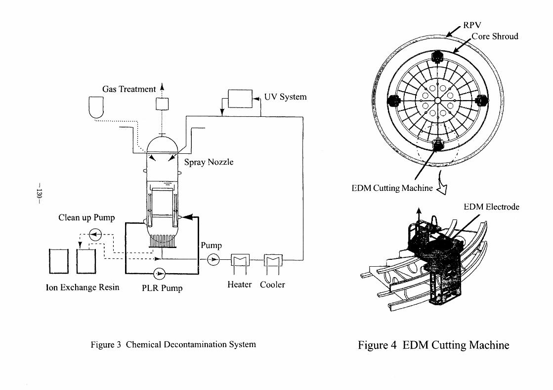
2.1 Chemical Decontamination
Prior to cutting the core shroud, the chemical decontamination was conducted. The
Chemical Oxidation Reduction Decontamination (CORD) process provides a high
Decontamination Factor (DF), and generates a small amount ofwaste in comparison to
other decontamination processes. Decontamination solution was circulated by the
Primary Loop Recirculation (PLR) pumps, and the dissolved active metal was captured
by ion exchange resins (Figure 3). In the core shroud replacement project for IF3, the
oxidation and reduction process was repeated three times in a week. The volume of
waste was approximately 5m3, and the DF measured under water was approximately 40
at the bottom of the RPV .
- 122 -
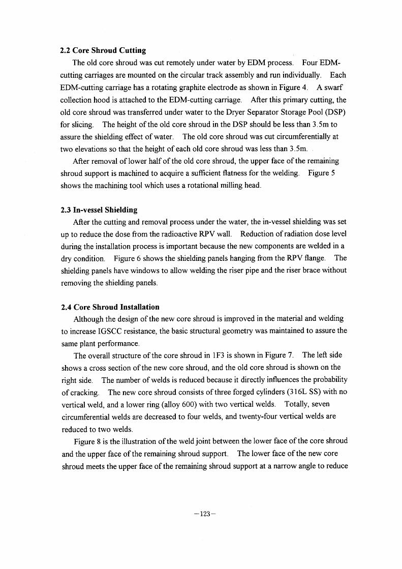
2.2 Core Shroud Cutting
The old core shroud was cut remotely under water by EDM process. Four EDM-
cutting carriages are mounted on the circular track assembly and run individually. Each
EDM-cutting carriage has a rotating graphite electrode as shown in Figure 4. A swarf
collection hood is attached to the EDM-cutting carriage. After this primary cutting, the
old core shroud was transferred under water to the Dryer Separator Storage Pool (DSP)
for slicing. The height ofthe old core shroud in the DSP should be less than 3.5m to
assure the shielding effect ofwater. The old core shroud was cut circunferentially at
two elevations so that the height of each old core shroud was less than 3 . 5m.
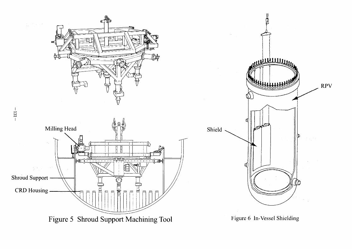
After removal of lower half of the old core shroud, the upper face of the remaining
shroud support is machined to acquire a sufficient flatness for the welding. Figure 5
shows the machining tool which uses a rotational milling head.
2.3 In-vessel Shielding
Afier the cutting and removal process under the water, the in-vessel shielding was set
up to reduce the dose from the radioactive RPV wall. Reduction of radiation dose level
during the installation process is important because the new components are welded in a
dry condition. Figure 6 shows the shielding panels hanging from the RPV flange. The
shielding panels have windows to allow welding the riser pipe and the riser brace without
removing the shielding panels.
2.4 Core Shroud Installation
Although the design of the new core shroud is improved in the material and welding
to increase IGSCC resistance, the basic structural geometry was maintained to assure the
same plant performance.
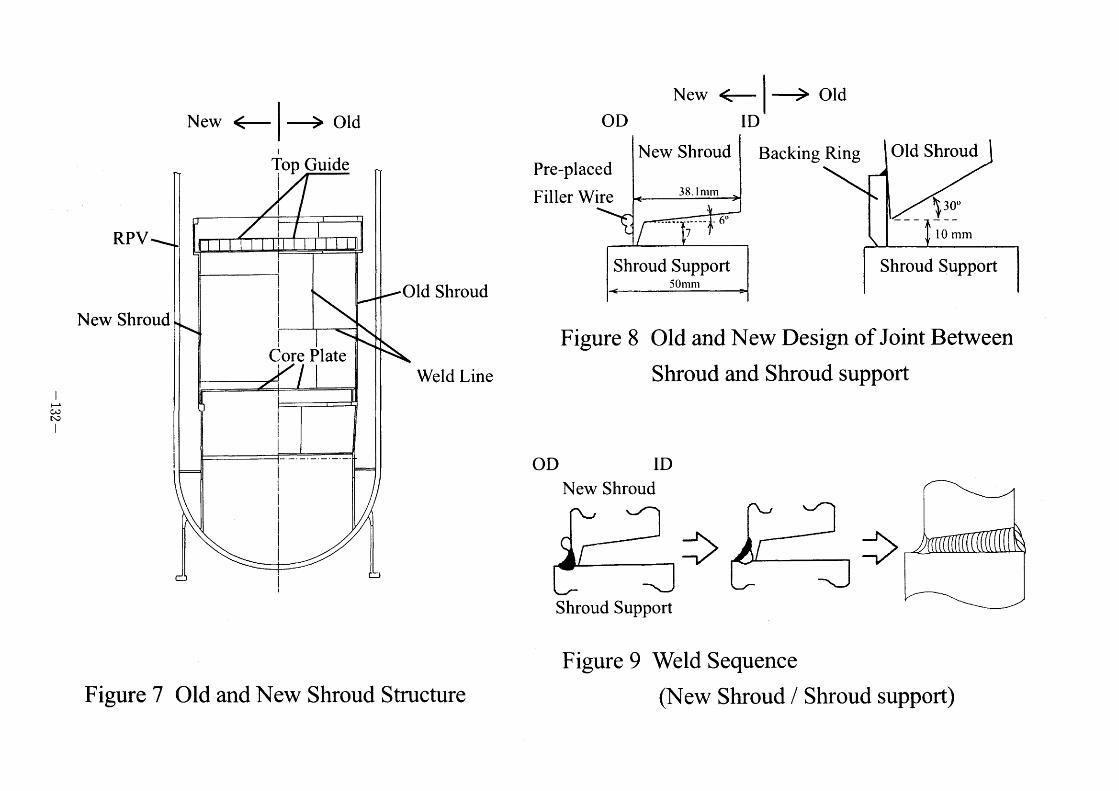
The overall structure of the core shroud in IF3 is shown in Figure 7. The left side
shows a cross section ofthe new core shroud, and the old core shroud is shown on the
right side. The number of welds is reduced because it directly influences the probability
of cracking. The new core shroud consists ofthree forged cylinders (3 1 6L SS) with no
vertical weld, and a lower ring (alloy 600) with two vertical welds. Totally, seven
circumferential welds are decreased to four welds, and twenty-four vertical welds are
reduced to two welds.
Figure 8 is the illustration ofthe weld joint between the lower face of the core shroud
and the upper face of the remaining shroud support. The lower face of the new core
shroud meets the upper face of the remaining shroud support at a narrow angle to reduce
- 123 -
welding heat input and to shorten welding time in comparison to the old core shroud.
In the old core shroud, the joint was welded from inside with the backing ring which
formed a crevice. In order to avoid a crevice in the weld joint and to get a smooth
configuration ofthe outside surface, the new core shroud was welded from both sides.
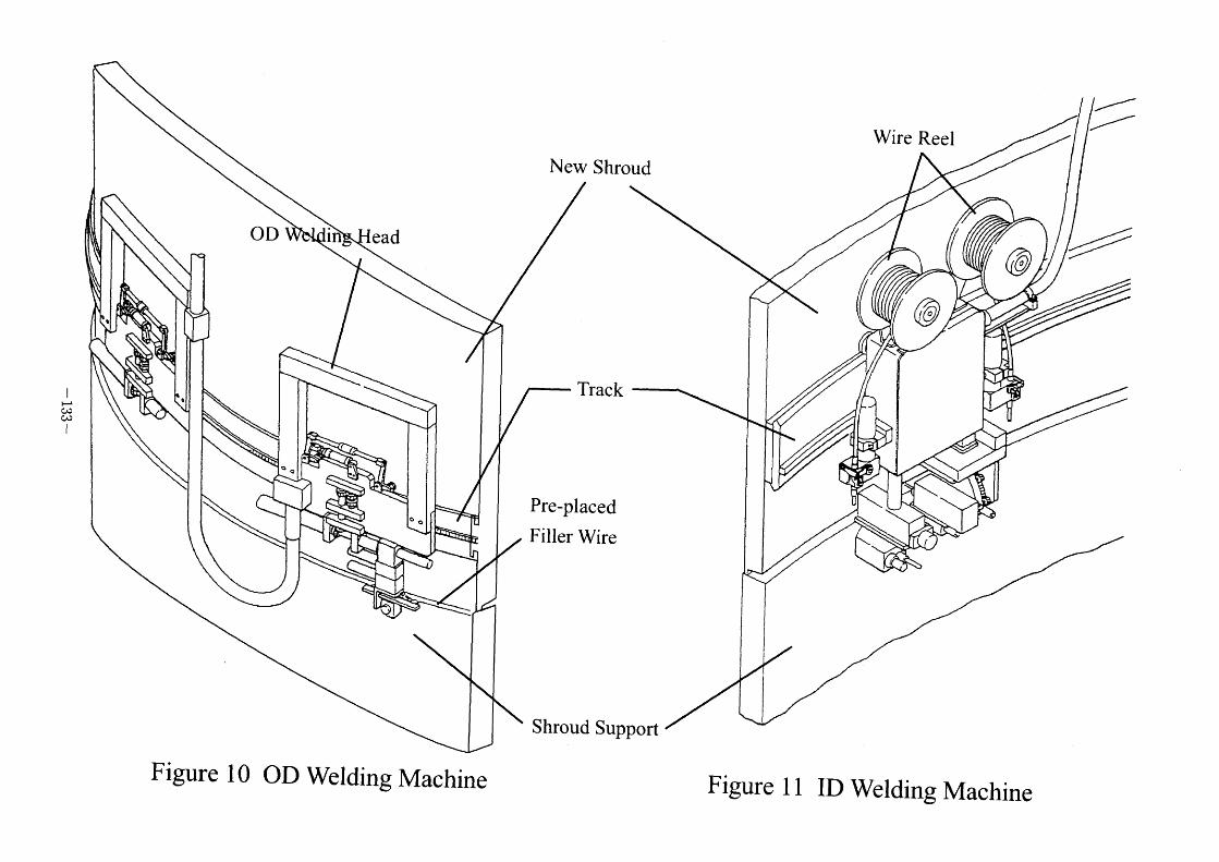
Figure 9 shows the bead sequence ofthe weld joint. Tungsten Inert Gas (TIG)
welding was applied. First, the outer diameter (OD) side was welded, and then the
inner diameter (ID) side was welded. Since the distance between the core shroud and
the jet pump difftLser is only 70mm at the joint elevation, the OD welding machine is thin
to fit the space, and was mounted on the OD track prior to the shroud installation as
shown in Figure I O. The filler wire was also attached on the outside ofthe new core
shroud prior to the shroud installation in order to save the space for wire feeding system.
The ID welding machines were attached manually after the new shroud installation, and
ran on the ID track remotely (Figure 1 1 ).
At the development stage of this welding process, the weld joint was evaluated by
visual test, penetration test, radiographic test, microstructure, metallography, side bend
test, crevice bent beam test (CBB), tensile bond strength test, and measurement of
hardness and residual stress. Based on the evaluation, the limit ofthe essential variables
for this welding method was established.
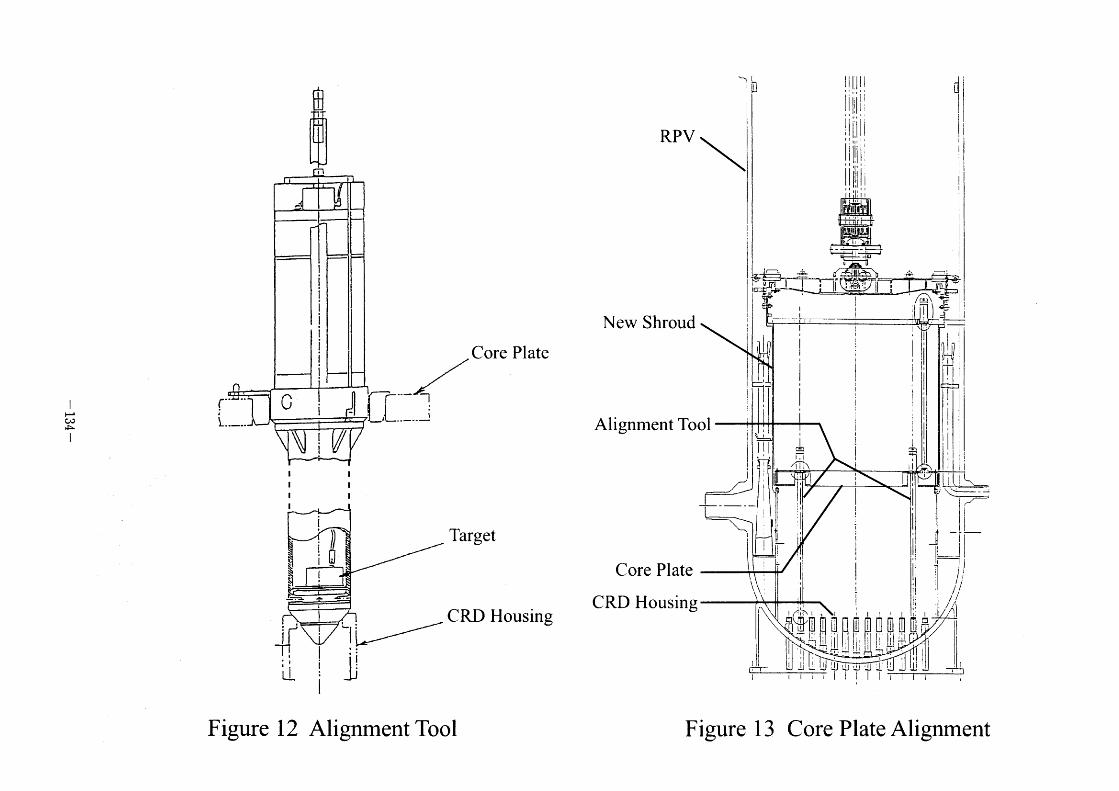
2.5 Alignment of the Components
It is important to align the core shroud, the core plate, and the top guide with the
CRD housings to secure appropriate motion ofthe control rods. Figure 12 shows the
alignment tool for the new core shroud, core plate and top guide. A Iaser targeting
system is set in the gas purged tube of the alignment tool. The new core plate was
aligned with respect to existing CRD housings as shown in Figure 1 3 . Bottom of the
alignment tools were set on the top of CRD housings, and top ofthe alignment tools
were fixed in the core plate master holes. The new core plate was aligned checking the
location of the core plate master holes and the CRD housings. The new core shroud
and the top guide are aligned similarly.
3. Waste Management
The removed core shroud and other components were sliced and put into the
containers in the DSP. The underwater plasma arc cutting was employed for the slicing
process because of its fast cutting speed. The stuffed containers were decontaminated
- 124 -
and transferred to the site bunker pool and the dry storage facility in the site.
all of the waste is low level radioactive waste, the site bunker pool stores more
radioactive waste.
Although
4. Conclusion
TEPCO is replacing the core shroud of IF3 to improve IGSCC resistance. The
shroud replacement is considered to be one of the most comprehensive countermeasures
to improve IGSCC resistance for all the welds ofthe core shroud. As of April 1998,
the new core shroud has already been installed properly, and the project is under
restoration process of other internal components. Subsequently, the core shroud
replacement will be performed in several Japanese BWR plants.
- 125 -
Top Guide
Core Shroud
Jet Pump
DP/LC Pipe
ICM Guide Tube
Figure 1 Replaced Components
- 126 -
Feed Water Sparger
Core Spray Sparger
Core Plate
l
Ht~
~]
(D ~) i
,F' ~)
Remove Fuel,
Core Componcnts
Chemical Decontamination Remove Upper Shroud,
Feed Water Spargers,
Top Guide
Remove Lower Shroud,
Core Plate, ICM Guide Tubcs,
DP/LC Pipe
Figure 2 ( I ) Replacement Sequence
H' t~D co
l
R
Remove Jet Pumps
O
Install Jet Pumps
Figure 2 (2)
R
/ /
'!.
Install Core Shroud
Replacement Sequence
li~ h
l
R
Weld Corc Shroud
l
H' N) ~)
l
~)
t
R ~
l
Instal] DP/LC Pipe,
ICM Guidc Tubcs
Install Core Plate, Top Guide,
Feed Water Spargcrs
Restore Fuel, Core Components
Figure 2 (3) Replacement Scquence
l
~'c'e
o
Gas Treatment L.
:.1.
Clean up Pump
r~e~~l YL_L'- ,
Ion Exchange Resin
UV System
~ Spray Nozzle
,
- - ->
'l>
PLR Pump
pump
-O ~I~ ~l~ Heater COOler
Figure 3 Chemical Decontamination System
RPV Core Shroud
OO O
OO
EDM Cutting Machine
o o
I
EDM Electrode
Figure 4 EDM Cutting Machine
' ~'~~/ .
l:Al
C O
\
;~C=- i~ I~'
::1lr !~!~~ //=1/ ~~
Q e
-- ~~
~
L.'
l
~S
~
Milling Head
Shrbud Support
CRD Housing
lr
,l
Shield ,p
RPV
Figure 5 Shroud Support Machining Tool Figure 6 In-Vessel Shielding
l
h' cJe t\D
RPV
N ew Shroud
Figure 7
-> Old +0p Guide
!
Old Shroud
Weld Line
Old and New Shroud Structure
New Old
Pre-placed New Shroud Backing Ring Old Shroud
38, I ~,,,,
' Io~~
Shroud Support Shroud Support 50~,~,
Figure 8 Old and New Design of Joint Between
Shroud and Shroud support
New Shroud
Shroud Support
Figure 9 Weld Sequence
(New Shroud / Shroud support)
I
~; c~
l
New Shroud
Wire Reel
,
,
OD
.
Figure I O
e
in ead
eo
OD Welding Machine
Track
Pre- placed
Filler Wire
Shroud Support
Figure 1 1
~
r
,
ID Welding Machine
~1!l
l
H ('o
~ I
~~-
rf_L I ///~ core ptate
~ i i Target ~~!
L/ CRD HOusmg ~i, I :=
~ :' ' L~I = I
Figure 1 2 Alignment TOOl
~1 = ~ Ill'll I d ':"ji l j I i !il ' ' l *,' [ :=' lllli
,
\ I i[ l!1 i : ,, ,',
,,'.' [ I Ill I ' j .l .. '' l...1= + : il li' ' ,,
"" I ~yll i * ,,, ~, l '- ' l! --~'~ ~:~i~ ~~ ~~~ ~ ~:+"__'~~:'1 ! l __ . '~~1[~711 : rL~~-*'
*t~i i'-*- Ij
New Shroud - ' ' '~' ' ,. . i, I~I!
l~li
c::~ l'
' 'l l
Alignment TOOI ! i ,I ~JL=' I i ii ~ ,
i, I ;..i = j l ll :~~ l ~ *l
"I 11' I 'll: . ,~ - .--. " I ~f~~!1( i [1 ~ ~JI I f' -.' l
' l l
l '\~f~ -\= H'i ' i jl.
L ( iii -fj___._.1[I ,*
I = "! ' ": =i = COre plate ; l: ! l' = !" ,
' ' ' 'l ll \\ 'I l t!
l i
*Il'l'l I~ '. , . : ' '1 '~1 '~f:~f'! ' ~ ' '~ I D'; ~ i ~'Oi'~~I~P// I ~Lli li !~"! =! ' l l i ~ = "II Il
~~~~~~~'~.-.LLI'J: Itl I ~' .=
Figure 1 3 Core Plate Alignment
III-4 The Evaluation of Erosion-Corrosion Problems of PWR Carbon
Steel Piping in Taiwan
Kuen Ting, Department of Nuclear Regulation Atomic Energy
Council, Taiwan, Republic of China
Yin Pang Ma, Institute of Nuclear Energy Research Atomic
Energy Council, Taiwan, Republic of China
THE EVALUATION OF EROSION/CORROSION PROBLEMS IN TAIWAN PWR CARBON STEEL PIPING
Kuen Ting Department of Nuclear Regulation
Atomic Energy Council Republic of China
Yin Pang Ma Institute of Nuclear Energy Research
Atomic Energy Council Republic of China
ABSTRACT Taiwan PWR Nuclear Power Plant Units I and 2 implemented the
measurements of the wall thinning of the carbon steel piping under the request of
regulation authority to prevent the events due to the erosion/corrosion since 1 989. At
the frrst, the licensee established the comprehensive inspection program by itself.
Over 2000 components were inspected per each unit and 300-500 pipe components
were examined by ultrasonio testing per soheduled outage. The simple predictive
methodology determined the operability of each individual piping oomponent in the
next fuel Gycle. Based on the inspection results, the susceptible pipe components
were established. The implementation of the effective correction management and
improved inspection program can improve the safety, as well as the efficiency, of
long-tenn reactor operations.
INTRODUCTION Erosion/corrosion is a piping degradation process that induces the pipe wall
thiming. The oxide layer on the carbon steel pipe is dissolved by single-phase or two-
phase flow in the nuclear power plant[1]. In 1 989, the regulatory authority requested
the licensee of Taiwan nuclear power plants to develop their own inspection program
to prevent the failure of piping due to erosion/corrosion damage. The licensee
established a full scope of pipe wall thickness database through "Pipe Wall Thiming
Measurement•Program"[2]. Over 2000 pipe components were selected per each unit and 300-500 pipe components were examined by ultrasonic testing per scheduled
outage. Based on the inspection results and the analytical method, the evaluation of
the susceptible pipe components in the licensee inspection program was established
during each scheduled outage. This paper will discuss the implementation of this
- 135 -

effeGtive management and the inspection program. The efforts can improve the safety,
as well as the efficiency, of long-term reactor operations.
INSPECTION PROGRAM In 1 989, after a severe piping rupture at Surry nuclear plant, the regulatory
authority requested the licensee to develop the plant specific-monitoring program to
prevent the failure of piping due to erosion-corrosion damage. The licensee, Taiwan
Power Company (TPC), established the comprehensive inspection program to
measure the thickness of most of the carbon steel piping components in the balance of
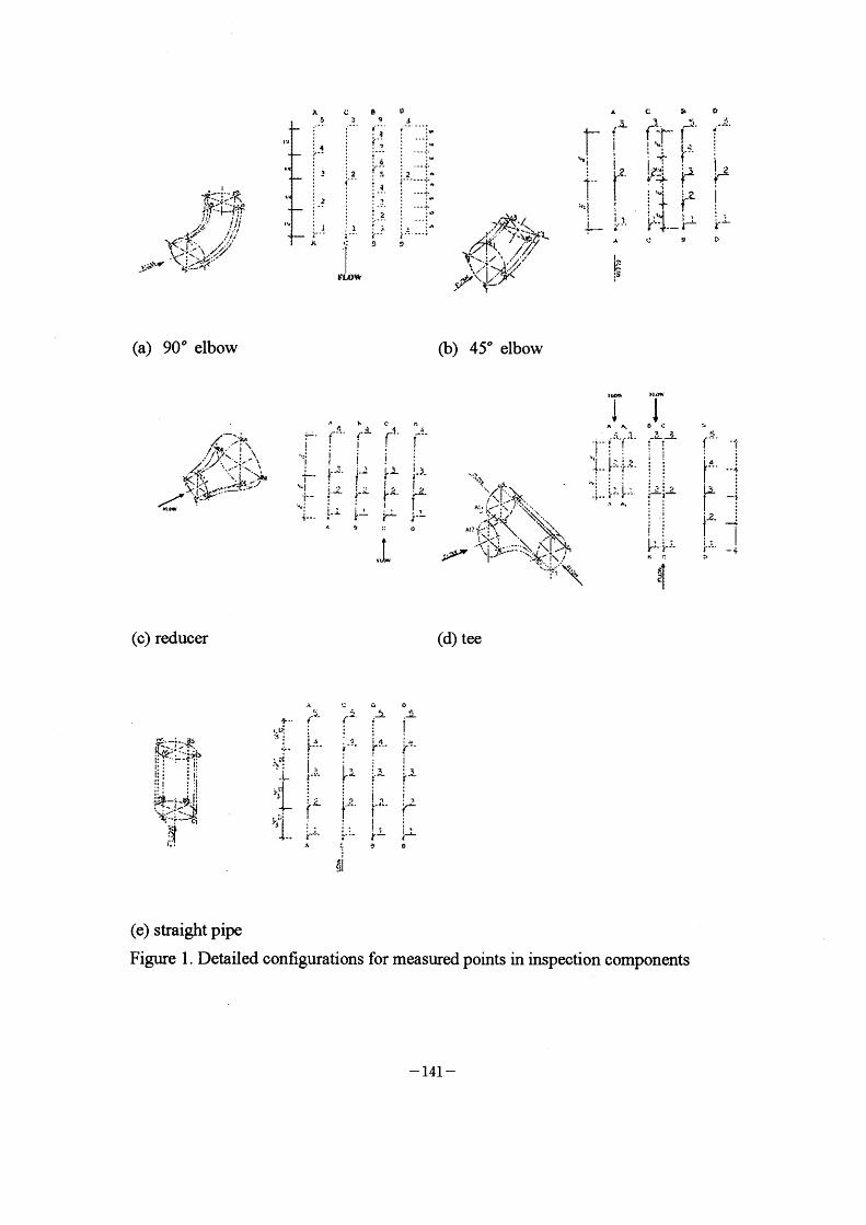
the plant. The inspeoted oomponents consist of straight pipes, elbows, tees and
expanders/reducers in the feedwater, condensate, extraction, heater drain and reheater
drain systems. The detailed configurations for measured points in each typical
component are displayed as Figure I .
The evaluation method of the inspection program is based on the measured data.
The thinning due to erosionfcorrosion wear T., oan be caloulated as
T,. = Tl ~ T,orT. - T. (ifno inspection data for reference)
T,. = (previous measured thickness)-(present measured thickness)
In which Tl and T. are the maxirnum and minimum measured thickness, respeotively. T~ is the nominal thickness. The wear rate can be defined as
W. = T.. IH
where H is the operating hours between two inspection intervals. The allowable
wear thickness T. is
T. =T. -T~ where T~ is the required thickness from the stress report or by analysis.
Thus, the remaining time of operation , L. ,can be estimated as
L. = T. /W.
The allowable number of remaining fuel cycles, I,al , can then be predieted as
lrd = L. l(KO.)
next fuel Gycle.
The tbtal number of the selected pipe components was greater than two
thousand per PWR unit. However, the oapacity ofrealistic ultrasonic testing was only
three to five hundred pipe components per outage. So, one PWR plant needs at least
seven outages to examine all selected oomponents and build up the complete database
of the wall thiming.
- 136 -

OBSERVATIONS OF THE INSPECTION The measured data from four outages have been studied according to the type of
the pipe components, such as 90" elbow, 45" elbow, reducer, tee and straight pipe.
Figure 2 displays the occurrences ofthe thinnest thickness versus measured points for
all inspeGted 90" elbows. The position B5 that is the outward bent of the elbow had
the majority of the occurrences of the thinnest thiGkness. Ahnost 700/0 of all inspected
elbows show that this region is easily erosive owing to the change of the flow
direction. This phenomenon is also found in the 45" elbow inspection as shown in
Figure 3 . The majority of the worst thinning occurs at the location B3 which is the
outward bent of the elbow.
For the erosion/corrosion of the reducer, the thinnest thickness locates at the two
ends Al, A4, Dl and D4 as shown in Figure 4. The fraction of these locations is
approximately 90010.
The distribution of the thiunest thickness is uniform for tee components in Figure
5. According to the experience, B and C sectors are not easily subjected to
erosion/corrosion. However, Figure 5 revealed that B and C sectors with 380/0 are the
positions of the thinnest thickness.
From Figure 6 presents the statistical distribution of the measured data for
straight pipe. The inlet position is the susceptible location for erosionfcorrosion as
antioipated.
THE EVALUATION OF THE POTENTIAL RISK OF THE CARBON STEEL PIPING UNDER EROSION/CORROSION
The ultrasonic inspection program of earbon steel piping due to erosionfcorrosion was
oomprehensive. An analytic method to evaluate the potential risk of the carbon steel
piping subjected to erosion/corrosion is necessary. Berge's model[3] assumed the
soluble iron species production and mass transfer effect on the erosion corrosion rate.
Thus, the total erosion/corrosion rate Vc is expressed as:
V KIK2 (C,q - C.) c ~ Kl +K2
where C~ is the soluble ferrous ion concentration at the bulk water; Kl is the
reaotion constant which depends on fluid velocity and water temperature; K2 is mass
transfer coeffilcient which depends on the Sherwood number Sh = al Re"' Sc"= , Re
and Sc are the Renolds number and Schmidt number, respectively; al ' a2 and a3
- 137 -
are constants which depend on the pipe component geometry. C,q is the equilibriurn
soluble ferrous ion conoentration at the oxide layer which depends on the pH value
and the coolant temperature. In present work, C,q is expressed as
C.q a exp[~(T -a5)2 J +a7
a6
where these constants are dependent of pH values.
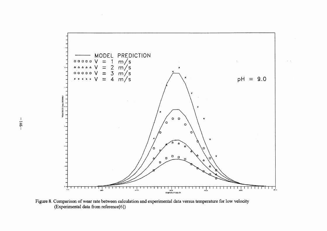
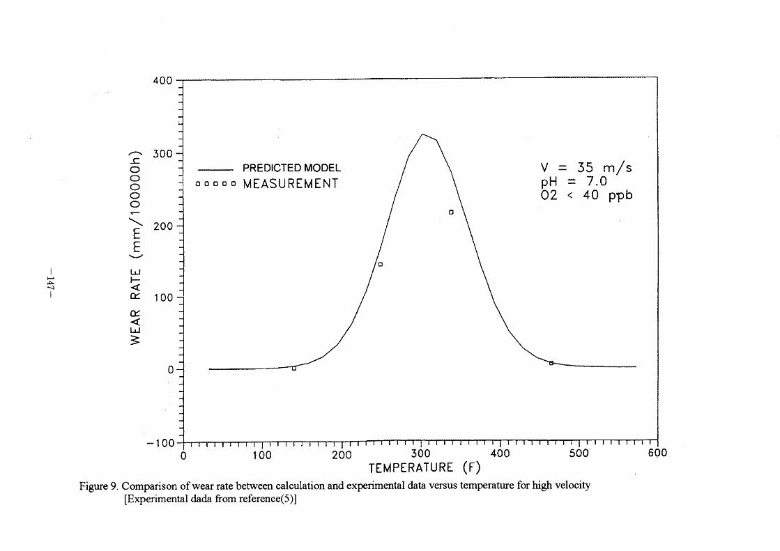
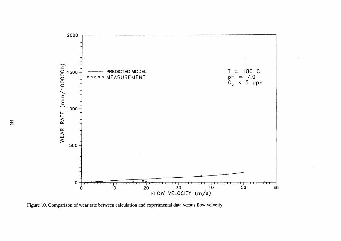
The calculation results of the present model are in good agreement with the
referenced data from the previous experimental works [4-6] as shown in Figure 7, 8
and 9 . The parameters studied here are simulation to the realistic environments of
PWR nuolear power plants. The values of pH, the fluid temperature and fluid velocity
in PWR are fanged from 8.9 to 9.5, 300"C to 500"C and Im/sec to 4m/sec. The
presented model also shows the good relations with the measured data of the PWR
realistic oonditions ranging from 120"C to 230"C and the velocity over Im/s.
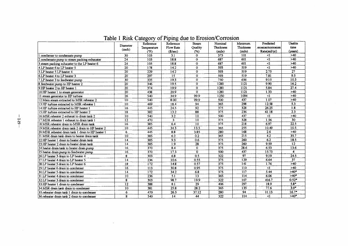
Based on the predicted analysis, the carbon steel piping system, such as
condensate system, feedwater system, main steam system, extraction steam system
and drain system, are oategorized into 36 groups to evaluate the potential relative risk
of the pipe systems of the PWR plant under the attack of erosion/corrosion. The frrst
column of Table I shows the categorized groups which are divided by the critical
component. For example, the critical components of the feedwater system consider as
feedwater pump, HP heater I and 2, steam generator. Thus, the feedwater system is
oategorized as three groups to evaluate the behaviors with erosion/oorrosion. The pipe
diameter, flow rate, steam quality nominal thickness and allowable thiekness are the
input parameter for the prediction of the rate of erosion/corrosion and the life of the
carbon steel pipe components as listed in the last two column of Table I . The
superscripts "*" notes "the not-used-normally" pipe components which are not used
during normal operation. The pipes from the 3'd stage feedwater heater dump to the
condenser are the most dangerous pipes for not-used-normally pipes, if the upstream
level oontrol valves of the pipe components are leaking, the water flashing in the level
control valves due to the high pressure gradient across the valves may cause the wall
thickness of the down stream pipe components to thin and exceed the limitation
within one fuel cycle[7].
RESULTS AND DISCUSSIONS Based on the prediction as mentioned above, the damage of the two-phase pipe
- 138 -
components is worse than the single-phase pipe components. The extraction lines
from the high pressure turbine to the frrst stage feedwater heaters in which the steam
quality is ranges from 880/0 to 950/0 were the high risk of the erosion/oorrosion. The
pipe components in the following pipes are also highly susceptible, suoh as:
(1). from the 4th stage feedwater heaters to the 3'd stage feedwater heaters ,
(2), from the '3'd stage feedwater heaters to feedwater pumps,
G). from the drain pumps to the feedwater pumps,
(4). from the 2~d stage feedwater heaters to the drain tank,
(~)• from the drain tank to the drain pumps, (~). from the 2~d reheater to the first feedwater heaters.
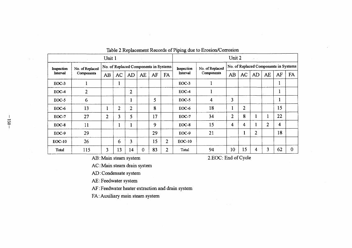
Table 2 desGribes the records of the replacements of the pipe components during
each outage. The extraction lines and the exhaust lines are the highly replacement rate
whieh are consistent with the predicted work as shown in Table I .
CONCLUSION The actual operating conditions in the nuclear power plants cannot be effectively
eontrolled as stringently as in the laboratory, and the analyiical predictions and
inspection program are not so reliable as anticipated. To avoid the erosion/eorrosion
damage, the current inspection program should be improved by a proper analyiical
method and engineering j udgment.
The present work provides a pipe erosion/corrosion inspeetion program and
analytical method to assist the relevant engineers in making engineering judgnlent and
to find out the susceptible pipe components and to evaluate the relative potential risk
of the pipe components . The results are helpful for the engineers to renew and audit
the monitoring prioritization of the pipe components.
REFERENCE l. U. S. Nuclear Regulatory Commission Bulletin 87-0 1 , "Thinning of pipe walls in
nuclear power plants," July 9, 1 987.
2. Taiwan Power Company, Nuclear power plant pipe wall monitoring program,
NED-NPS-OOOl, R2, TAIPOW, June, 1989. 3. J.P. Berge et al., Effect of chemistry on corrosion-erosion of steels in water and
wet steam, Proceeding of 2~d Conferenee on Water Chemistry, BNES, 1 980.
4. ASM Intemational Handbook Committee, Metals Handbook, 9th edition, Vol.13,
Corrosion.
5. J.P. Gof~m. Thickness measurements of pipes submitted to erosion and corrosion
problems in the steam, feedwater and condensate systems of the Doel I and 2
power plants, Intemational Atomic Energy Agency (IAEA) Specialist Meeting on
- 139 -
6.
7.
ErosionfCorrosion, September 1 2-14, Vienna, Austria, 1 988.
M. Bouchacourt, Flow assisted corrosion in power plants-part I : The EDF
research program, Intemational Atomic Energy Agency (IAEA) Specialist Meeting on Erosion/Corrosion. September 1 2-14, Vienna. Ausina, 1 988.
H.J. Chao and Y.P. Ma, User's manual for nuclear power plant pipe erosion/corrosion data base system, INER- 1 2 1 5, May, 1 994.
- 140 -
t I J~I>~T '(rt 1~.'5!-1":~
! r' : , l" ' ih //'~l' : ., . l.j'l! -~i l' t~~: ,• ' /'/ \~/\ I (\-~\*;:i4i//
"$!"I/ 5~:-~-'1~(" ,;.'
I~,
I1,
L1
It
A 5
il
:2
'L
e D 9 J t 8 f :"
: 2 :"' r~~ i-'--- t"' : _a_'
:'p
:2
; I :"' . t'- t.. .. 'f !; 9
rLOW
?/~ir~~:i ~' 'l
\ '/:~~~~~/ \ ,.1; '
(/~~{~ll,'!~. / //7/'
~~... : ( ~, '/;'
~•"/~~ -S;-~cl\
~'-' 7
A
,, r ~ /'~ i
It
, 2' i-- f
:'i l' : i ! _ '_
~i A
I" *:
~.
c ':' f-- ~' r l F* I
I '*, , . 1~ ! " f' v' i"i ' :~L*' ;~~~ ,
rl~ ? : 'Q: ; 't i + rc .t4 ~ .
~ .- i ~:
,,
d
i' ~~'
i
t~ t)
(a) 90" elbow (b) 45" elbow
,. , \ "I)i~ ;c-~ ~
'_/(~;" t' ' I.\ t ~K I(~ ~. /\/t~4. "~:L " ~__ ~] f~le~~:. /~' -'1:
/ " ~ ' '~~~ ~,
""I':
i
i
I
'h f
l~ -
4...
A t c rt /' *' -- " !L 4 r ' r ' I~'~ ? , , I I_ i i .. i-i L .1 { I')-.~ , . ' f . , :> . l I'~t ;~ ~L , r r~ I
: I l-i '~ ~ }-L A 9 a: o
.~
**.*~
" '~i' ' AI _ ::'~~ !~"'~f~~1'~~~, y?r\:..~ \
" /\fs-pr '\1- ' - \~* ~ l '~:'. !\.!
'lJ~ I
A A: ' ' :)~-' f i '
f } : : ' -- ' I
':{-- f, ~ ';•'-- ,~
~,: '~" ?J-~'L
~ At
)i'l~ J
eC rL J_~
i i
~= ; JL
i
if ~-. : - ;-
? l,.
~?i~il
:~
5i
r'~~~ -ir
f'-' ": 4 ;
r -~ .LJ3. :
~e I ' :- l }_lL _~
(c) reduoer (d) tee
~, ~L.. 85
I: '
l:: ' :1: l: : i I;
i: i : :!
;~,;~
,~L
lp - - rf-1$-
l' v! ; :1' ' : 's I'-- - -
Y. t~ ' " ; i " -L r-' v5~ r tl'~': : ;_1b
J_ i i
' r A
o o r ~ 'jL ' ~ ,L ,. J-; I' ~ 14 "a '~~' r~~~ t'~
f ! ;~ ! ::1 4 r JL .L Jh
lo' I~ f f" ' " "-(' rLi :5 t
;_i I ' ; i, - rL -L f
eL o ~Ji
~
(e) straight pipe
Figure I . Detailed configurations for measured points in inspection components
- 141 -
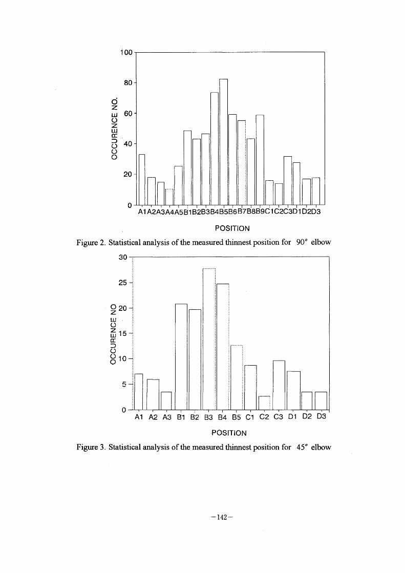
Figure 2.
Figure 3 .
o z UJ
~ ~ o o O
A1 A2A3A4A5 ~ I B2B3B'4B5B6 B7 B8B9d I C2C3D I D2D3
POSITION
Statistical analysis ofthe measured thinnest position for 90" elbow
i OO
80
60
40
20
o
A1 A2 A3 ~l B2 B3 B4 B5 C1 C2 C3 D1
•POSITION Statistical analysis of the measured thimest position for
30
25 ~
Oz 20 ~
Lu : O i zuJ15•~,~ cc = D : O : O = OIC1
O D2 D3
45" elbow
- 142 -
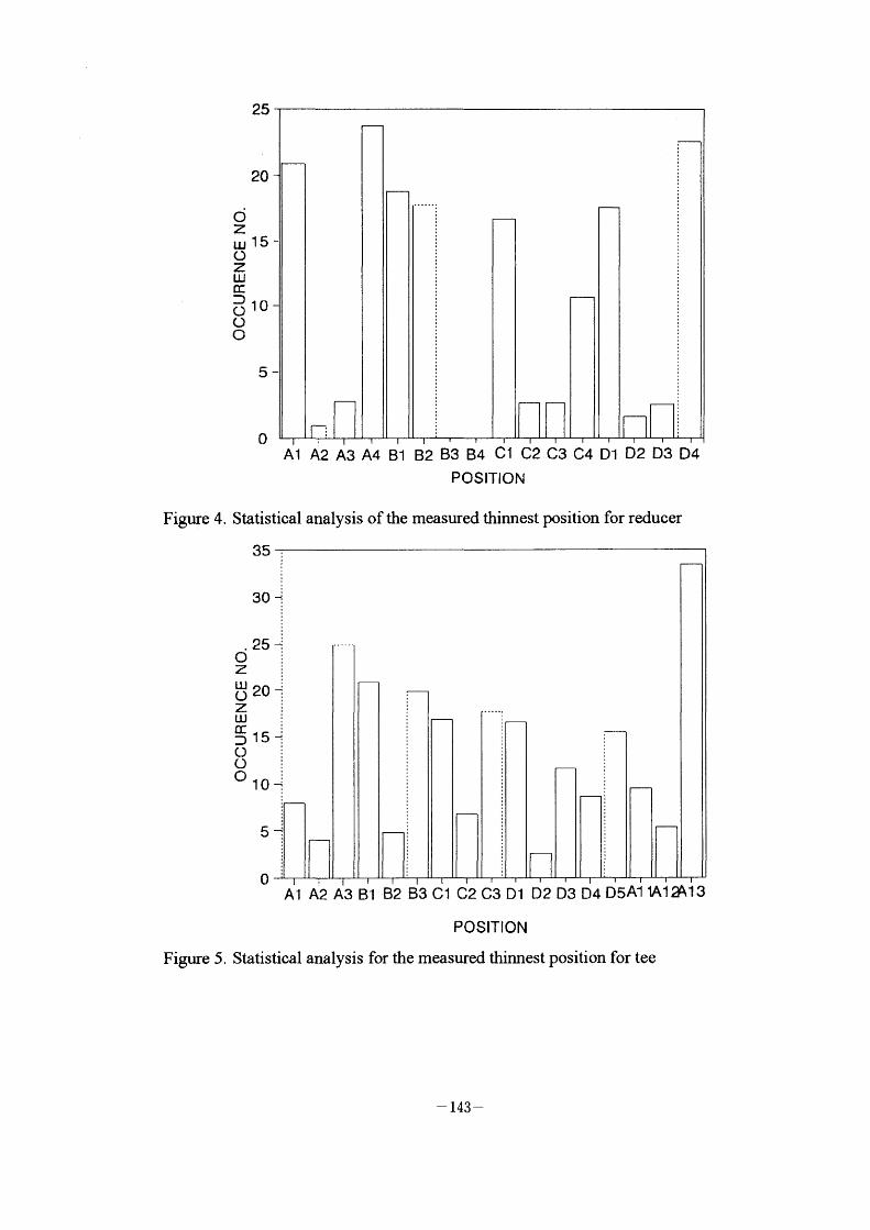
Figure 4.
Figure 5.
25
20
d z UJ 15 ~
o z UJ
~ D o 10 o O
5-
O A1 A2 A3 A4 B1 B2 B3 B4 C1 C2 C3 C4 D1 D2 D3 D4
POSITION
Statistioal analysis of the measured thinnest position for reducer
35 -:
A1 A2 A3 B1 B2 B3 C1 C2 C3 D1 D2 D3 D4 D5A1 IA12~l3
POSITION
Statistical analysis for the measured thimest position for tee
30 +
25 ~ c; ; z : LLl~ = O 'O ~
z i UJ : CCD 15 _•~
O i O : OIO~
5~
O
- 143 -
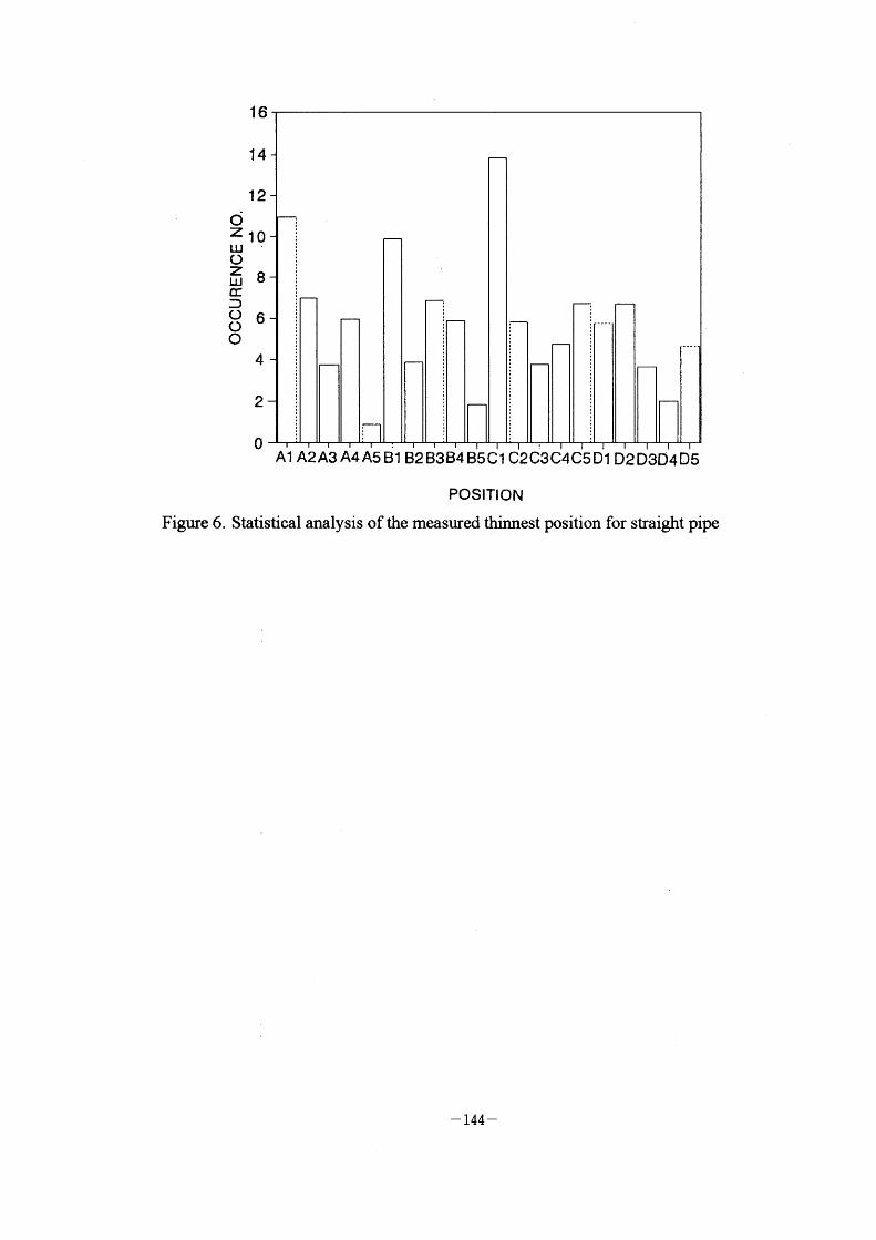
Figure 6.
16
14
12 C;
Z 10 LLJ' O ~8 GC :)
86 O
4
2
O A1 A2A3 A4 A5 ~l B2 B3B4 B5C1 C2d3C4C5D1 D2 D3D4D5
POSITION Statistical analysis of the measured thinnest position for straight pipe
- 144 -
AB
I
~. J~ Ol
l
S/G
HP CJ
AF
RHTR
RE:lR
SPR
AF
Lp
~
~
1 AE
~
Fwr
~
~
~ AF
AE) DP
AD
~
LP
AD
3 AD AD
AD
AF
4
AF
5 AD 6
ssn
CONDENSER
AF sPE
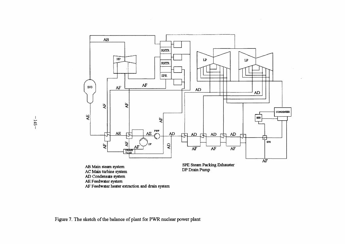
AF AB Main steam system AC Main turbine system AD Condensate system AE Feedwater system AF Feedwater heater extraction and drairL system
SPE Steam Packing Exilauster DP Drain Pump
Figure 7. The sketch of the balance of plant for PWR nuclear power plant
,.
I
~' ~ cr)
~ ^ ^ ~
'i
,, *~'
*
1
,
MODEL OOODO V = 1 AAAAA oooooV = 3 x**x*V = 4
PREDICTION m/s m/s m/s m/s
x
x
X pH = 9.. o
x
x
X
,c
o
o oo
A A
o
d~
o
x
o
X
o
o o o o o
A o
A
X
IQI,,, .~::~ e.
fC,,,•',:~.1."~;ffh,1,) d'.,, ,•. .~II 'l.
Figure 8. Comparison of wear rate between calculation and experimental data versus temperature for low velocity
(Experimental data from reference[6])
I
~' ~ ~]
I
400
- 300 ~:
O O O O O = \ 200 E E
~ LJ ~ O( I OO Q(
LU ~
o
- I OO
OODOD PREDICTED MODEL MEASUREMENT
D
o
V= pH = 35
7.
40
m/s pp b
Figure 9.
TEMPERATURE (F) Comparison of wear rate between calculation and experimental data versus temperature for high velocity
[Experimental dada from referenee(5)]
6Qo .
l
~. d~ oo
l
2000
~ ~. Oo 1500
O O O -\ E E
~ I OOO UJ H Q(
Q(
LJ ~
500
o
DOOOD PREDICTED MODEL MEASUREMENT
D
T pH 02
180 C 7.0 5 ppb
o 10 20 FLOW
30 VELOCITY
40 (m/s)
50 60
Figure lO. Comparison of wear rate between calculation and experimental data versus flow velocity
,-,
~ ~o
Table l Risk Category of Piping due to Erosion/Corrosion
l
~:;
o I
Table 2 Replacement Records of Piping due to ErosionfCorrosion
AB : Main steam system
AC : Main steam drain system
AD : Condensate system
AE : Feedwater system
AF : Feedwater heater extraction and drain system
FA : Auxiliary main steam system
2 . EOC : End of Cycle