Embed Size (px)
Citation preview

© Copyright Engineering Research Center for Net Shape Manufacturing, 2012
Stamping Group
CPF
Servo Press Technology
Applications for Today and Tomorrow
Eren Billur and Taylan Altan
Center for Precision Forming
The Ohio State University
www.cpforming.org & www.ercnsm.org
Webinar – MetalForming Magazine
August 23, 2012 – 2:00-3:00 pm EST
© Copyright Engineering Research Center for Net Shape Manufacturing, 2012
Stamping Group
CPF
2
Servo-Drive Presses- Outline
• Introduction
• Servo-Drive Characteristics
• Servo-Drive Press Mechanisms
• Applications
• Die Cushions
• Summary/ Future Outlook

© Copyright Engineering Research Center for Net Shape Manufacturing, 2012
Stamping Group
CPF
3
(4) Other Process
at BDC
(Multi Process)
(4) Other Process
at BDC
(Multi Process)
(5) Prevention of
noise and shock
at contact or
breakaway of
tools
(5) Prevention of
noise and shock
at contact or
breakaway of
tools
(6) Synchronize with
feeder
(6) Synchronize with
feeder
Crank or Link pressFixed Motion
Time
Sli
de
Po
sit
ion
Cycle time of mechanical pressCrank or Link press
Fixed Motion
Time
Sli
de
Po
sit
ion
Cycle time of mechanical press
(2) Best speed
for materials
(2) Best speed
for materials
For
min
g l
ength
(2) Best speed
for materials
(2) Best speed
for materials
For
min
g l
ength
(3) Improve
accuracy by
dwelling at BDC
(3) Improve
accuracy by
dwelling at BDC
Standstill at BDC
(3) Improve
accuracy by
dwelling at BDC
(3) Improve
accuracy by
dwelling at BDC
Standstill at BDC
(1) Variablestrokelength
(1) Variablestrokelength
Min
imu
m s
troke
leng
th
(1) Variablestrokelength
(1) Variablestrokelength
Min
imu
m s
troke
leng
thCycle time of
Free motion press
Free motion press
Cycle time of Free motion press
Cycle time of Free motion press
Free motion press
The flexibility of slide motion in servo drive (or free motion) presses. [Miyoshi, 2004]
Servo-Drive Characteristics

© Copyright Engineering Research Center for Net Shape Manufacturing, 2012
Stamping Group
CPF
4
Servo-Drive Characteristics
• Precise ram position and velocity control, anywhere in
stroke
• Adjustable stroke length (TDC and BDC)
• Ram position/ velocity can be synchronized with automatic
part transfer
• In deep drawing, cycle times can be shorter than in
mechanical presses
• Considerable savings in energy
• Dwell at BDC/ restriking/ vibrating and variable blank
holder force (BHF)
• Max. motor torque available during the entire stroke

© Copyright Engineering Research Center for Net Shape Manufacturing, 2012
Stamping Group
CPF
5
Servo-Drive Mechanisms
• Low Torque/ High RPM Motors Use Ball
Screws or/and Linkage Mechanisms
• High Torque/ Low RPM Motors Use
Existing Crank and/or Link Press Drives
© Copyright Engineering Research Center for Net Shape Manufacturing, 2012
Stamping Group
CPF
6
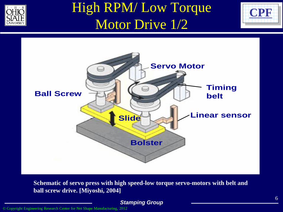
High RPM/ Low Torque
Motor Drive 1/2
Servo Motor
Ball Screw
Slide
Bolster
Linear sensor
Timing
belt
Schematic of servo press with high speed-low torque servo-motors with belt and
ball screw drive. [Miyoshi, 2004]

© Copyright Engineering Research Center for Net Shape Manufacturing, 2012
Stamping Group
CPF
7
Schematic of servo press with high speed-low torque servo-motors with linkage
drive. [Miyoshi, 2004]
Servo Motor
Slide
Eccentricload
Right / Left independent control
Linearsensors
Servo Motor
Linearsensors
Slide
Eccentricload
Right / Left independent control
Linearsensors
Servo Motor
Linearsensors
High RPM/ Low Torque
Motor Drive 2/2

© Copyright Engineering Research Center for Net Shape Manufacturing, 2012
Stamping Group
CPF
a) C-Frame Servo Press (Aida)
Power Source Balancer tank Main gear
Servomotor
Capacitor
Drive Shaft
8
Low RPM/ High Torque
Motor Drive 1/2
b) Stroke-Time program for warm
forming of Al and Mg sheet

© Copyright Engineering Research Center for Net Shape Manufacturing, 2012
Stamping Group
CPF Low RPM/ High Torque
Motor Drive 2/2
9
Servo-Press Drive Using Conventional Crank Mechanism
Courtesy- Aida

© Copyright Engineering Research Center for Net Shape Manufacturing, 2012
Stamping Group
CPF Hybrid Servo Press
Block diagram of a hybrid servo press (ABB) 10
© Copyright Engineering Research Center for Net Shape Manufacturing, 2012
Stamping Group
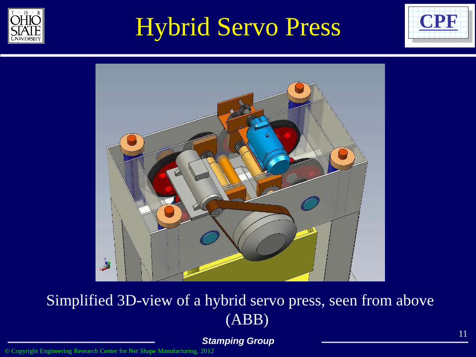
CPF Hybrid Servo Press
Simplified 3D-view of a hybrid servo press, seen from above
(ABB) 11

© Copyright Engineering Research Center for Net Shape Manufacturing, 2012
Stamping Group
CPF
12
Modern Stamping Lines Using
Large Servo-Drive Presses
• BMW- Leipzig & Regensburg (Germany) – SCHULER
2009 - 2500 ton servo-drive drawing press - 17 SPM
• BMW – Leipzig, Regensburg and Shenyang (China) –
SCHULER – 2012 – 7 tandem lines on order.
• HONDA - Suzuka (Japan) – AIDA 2009 – 2500 ton
tandem line – 18 SPM
• Kamtek/COSMA – AIDA 2011 - 3,000 ton, 30
strokes/min
• Honda-America – Ohio and Alabama - AIDA 2012 -
2,500 ton tandem lines
• Hyundai – Korea – ROTEM 2012 – 1000 ton Tandem line
• Others ?

© Copyright Engineering Research Center for Net Shape Manufacturing, 2012
Stamping Group
CPF
Improved
Formability
Improved
Productivity Energy-Saving
・System with optimized press
forming requirements for each
product
・Press-to-Press Loading Motion:
System is optimized for each
product.
・Die cushions have an energy
regeneration system
13
Schematic of Servo-press tandem line (Aida/Honda)
2500 ton/ 18 SPM (2009)

© Copyright Engineering Research Center for Net Shape Manufacturing, 2012
Stamping Group
CPF
14
Servo-press tandem line (Schuler/BMW)
2500 ton/ 17 SPM (2009)
One drawing press + 5 presses for follow-up operations
Source:BMWarchive.de
Technical Data:
Total press force: 10,300 tons
Drawing press force: 2,500 tons
Total length of press line: 98 meters
Length o press: 34 meters
Strokes per minute: 17
Source:Schulergroup.com

© Copyright Engineering Research Center for Net Shape Manufacturing, 2012
Stamping Group
CPF
15
Servo Tandem Line at Suzuka (Japan) Plant
(Honda)

© Copyright Engineering Research Center for Net Shape Manufacturing, 2012
Stamping Group
CPF
16
Comparison between the slide motions of an 1100 mechanical and servo drive
press for identical slide velocity during forming [Bloom, 2008].
Applications- Deep Drawing 1/3
(Courtesy- Schuler)

© Copyright Engineering Research Center for Net Shape Manufacturing, 2012
Stamping Group
CPF
17
Decrease in cycle time by reducing the stroke length and operating the servo
press in “pendular” mode (progressive die stamping, 200% increase in output)
[Bloom, 2008]
Applications- Deep Drawing 2/3
(Courtesy- Schuler)

© Copyright Engineering Research Center for Net Shape Manufacturing, 2012
Stamping Group
CPF
18
Decrease in cycle time as well as in impact speed using a servo press (150%
increase in output) [Bloom, 2008]
Applications- Deep Drawing 3/3
(Courtesy- Schuler)

© Copyright Engineering Research Center for Net Shape Manufacturing, 2012
Stamping Group
CPF
19
Side Panel Outer Deep Drawing Case
Example (Honda)

© Copyright Engineering Research Center for Net Shape Manufacturing, 2012
Stamping Group
CPF
20
Applications- Blanking/ Ironing
Slide motion used for partial and
finish blanking [Miyoshi, 2004 /
Komatsu]
Precision Formed Part a) partially
blanked, b) finished blanked
[Miyoshi, 2004 / Komatsu]

© Copyright Engineering Research Center for Net Shape Manufacturing, 2012
Stamping Group
CPF
Item : Eye glass frame
Material : Titanium based Shape-memory Alloy
By multiple step motion,
Three processes turned
into single process.
Three processes had been
required to control the
springback.
Multiple step motion
21
Applications- Reduction of Springback
(Courtesy- Komatsu/ Hamamoto)

© Copyright Engineering Research Center for Net Shape Manufacturing, 2012
Stamping Group
CPF
IT IS POSSIBLE TO DIGITALLY SET
THE OPTIMAL WORKING SPEED,
THEREBY INCREASING DIE LIFE.
SUS304
PIERCING A HOLE WITH A
SMALLER DIAMETER THAN
THE MATERIAL THICKNESS
(INCLINED HOLE PIERCING)
Al
STEPPED HOLE PIERCING
(80% BURNISHED SHEAR
FACE)
22
Applications- Blanking/ Ironing Courtesy – Aida)

© Copyright Engineering Research Center for Net Shape Manufacturing, 2012
Stamping Group
CPF
SINCE THE PRESS CAN BE RUN AT LOW SPEEDS, IT IS NOT
NECESSARY TO SWITCH TO A LARGER CLASS PRESS TO
FORM HARD-TO-DRAW MATERIAL.
WRINKLES CAN OCCUR WHEN
THERE IS INSUFFICIENT PRESS
RIGIDITY AND THE DRAWING
SPEEDS ARE NOT OPTIMIZED.
DRAW WRINKLES CAN BE
AVOIDED BY SLOWING DOWN
THE DRAWING SPEED. (SINCE WORKING ENERGY IS ALWAYS
AVAILABLE, THE PRESS DOES NOT STOP
EVEN AT INCHING SPEEDS.) 23
Applications- Blanking/ Ironing (Courtesy – Aida)

© Copyright Engineering Research Center for Net Shape Manufacturing, 2012
Stamping Group
CPF
IT IS POSSIBLE TO SET THE
OPTIMAL FORMING MOTION AND
TIMING FOR SECONDARY
PROCESSES.
(STAKING AND ASSEMBLY)
ASSEMBLY OPERATION OF A
SQUARE NUT (M5) IN A BRACKET
DURING A PROGRESSIVE FORMING
OPERATION
STAKING A PIN (∅3.6) IN A CHASSIS
DURING A PROGRESSIVE FORMING
OPERATION
24
Applications- Auxiliary Operations (Courtesy – Aida)

© Copyright Engineering Research Center for Net Shape Manufacturing, 2012
Stamping Group
CPF
Tool and process design guidelines to improve formability
Aida Servo Press (used in warm forming of Al, Mg and Ti sheet)
Power Source Balancer tank Main gear
Servomotor
Capacitor
Drive Shaft
25
Applications- Warm Forming of
Al, Ti, Mg, and SS
© Copyright Engineering Research Center for Net Shape Manufacturing, 2012
Stamping Group
CPF
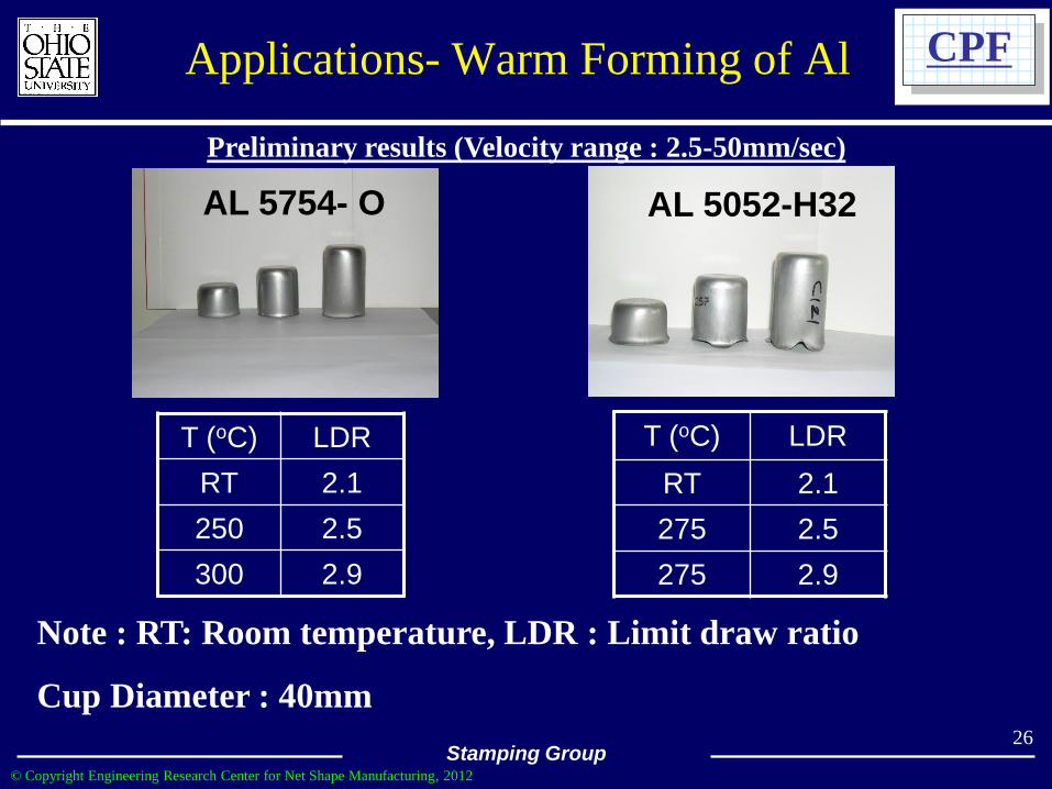
AL 5754- O
T (oC) LDR
RT 2.1
250 2.5
300 2.9
T (oC) LDR
RT 2.1
275 2.5
275 2.9
AL 5052-H32
Preliminary results (Velocity range : 2.5-50mm/sec)
Note : RT: Room temperature, LDR : Limit draw ratio
Cup Diameter : 40mm 26
Applications- Warm Forming of Al

© Copyright Engineering Research Center for Net Shape Manufacturing, 2012
Stamping Group
CPF
T (oC) LDR
RT -
275 2.6
275 3.2
Mg AZ31-O
Preliminary results (Velocity range : 5-50mm/sec)
Note : RT: Room temperature, LDR : Limit draw ratio
Cup Diameter: 40mm
T (oC) LDR
310 2.5
Ti (Grade 1)
27
Applications- Warm Forming of
Mg and Ti

© Copyright Engineering Research Center for Net Shape Manufacturing, 2012
Stamping Group
CPF
28
Press slide motion used in warm
forming processes (TDC - Top Dead
Center, BDC – Bottom Dead Center)
Warm formed lap top case from Mg alloy
(Courtesy – AIDA)
Applications- Warm Forming of
Mg Lap Top Case

© Copyright Engineering Research Center for Net Shape Manufacturing, 2012
Stamping Group
CPF
Die
Cush
ion F
orc
e (k
N)
29 Elimination of Pressure Surge in the Die Cushion
Servo-Hydraulic Cushion
(Courtesy-Aida)

© Copyright Engineering Research Center for Net Shape Manufacturing, 2012
Stamping Group
CPF Capabilities of the Self-Driven Hydraulic
Servo Cushion
• pre-acceleration to reduce the impact speed
between the die and blank holder
• variable pressure / force capability to control
blank holder force/pressure during stroke
• prevention of momentary return of the cushion
after BDC to avoid pressure on the top of the part

© Copyright Engineering Research Center for Net Shape Manufacturing, 2012
Stamping Group
CPF
S
M
S/M
Power
Direction
Closed Hydraulic Circuit
Power Regeneration: Approx. 70%
Pump
Rotation
Direction
Motor Torque
Direction
Pressure Sensor
Linear
Scale
31
Servo-Hydraulic Cushion
(Courtesy-Aida)
During Down Stroke, Cushion Pressure Generates Power

© Copyright Engineering Research Center for Net Shape Manufacturing, 2012
Stamping Group
CPF Advantages of Servo- Press Technology
- Applications in Forming AHSS -
1. Major Challenges in Forming AHSS (DP, TRIP,
TWIP) include:
• lower formability (ductility) and higher probability of fracture
• variations in mechanical properties form batch to batch
• higher forming forces and high sheet/die interface pressures &
temperatures
• Excessive tool wear, rapid increase in down-force and large
reverse tonnage
• large springback due to large tensile strength
32

© Copyright Engineering Research Center for Net Shape Manufacturing, 2012
Stamping Group
CPF Advantages of Servo- Press Technology
- Applications in Forming AHSS -
2. Precise Ram Position (including dwell) and
velocity control
• allows for easier die set-up
• prevents noise and shock when the ram is contacting the
workpiece (hydraulic cushion with pre-acceleration)
• improves formability and reduces fracture by reducing ram
velocity during deformation (drawing, stretching and bending),
improves die/sheet lubrication by reducing temperature increase
at sheet/die interface
• reduces shock loading and reverse tonnage in blanking,
improves tool life
33

© Copyright Engineering Research Center for Net Shape Manufacturing, 2012
Stamping Group
CPF Advantages of Servo- Press Technology
- Applications in Forming AHSS -
3. Dwell at BDC and Pendulum Motion allows:
• dwell at BDC and restriking quickly through pendulum motion
before the formed material fully strain hardens, reduces springback
(die design is still very important)
4. Adjustable Stroke Length (TDC to BDC):
• provides flexibility so that in the same press, drawing, blanking
and coining can be conducted with maximum productivity (high
strokes/min) 34

© Copyright Engineering Research Center for Net Shape Manufacturing, 2012
Stamping Group
CPF Advantages of Servo- Press Technology
- Applications in Forming AHSS -
5. Ram Position/Velocity can be:
• synchronized with automatic (or robotic) part
transfer to increase strokes/min
• adjusted to maximize strokes/min while maintaining
lower ram velocity during forming stage
35

© Copyright Engineering Research Center for Net Shape Manufacturing, 2012
Stamping Group
CPF Servo-Drive Press Technology
Summary / Outlook
• Gap presses up to 150 ton are in production (15+ years)
• Straight Side stamping presses up to 3000 ton are already
built
• Direct drive (high torque) motors and energy recovering
cushions are used
• High speed automotive stamping transfer presses (18
strokes/min)/ Schuler-BMW/ Aida-Honda and Cosma /
Komatsu-Toyota & others
• Novel tool design techniques for servo drive technology are
being developed
• Servo-drive presses will greatly contribute to improving the
technology for forming AHSS 36

© Copyright Engineering Research Center for Net Shape Manufacturing, 2012
Stamping Group
CPF Questions/Comments
Taylan Altan, Professor and Director
Center for Precision Forming (CPF)
www.cpforming.org / www.ercnsm.org
The Ohio State University, Columbus, OH
Email: [email protected], Ph: (614) 292 5063
Source: Chapter 11 – Electro-mechanical
Servo-Drive Presses in “Sheet Metal Forming, Fundamentals”,
Vol. 1, by Altan/Tekkaya, ASM International, www.asminternational.org
37