Embed Size (px)
Citation preview
8075795
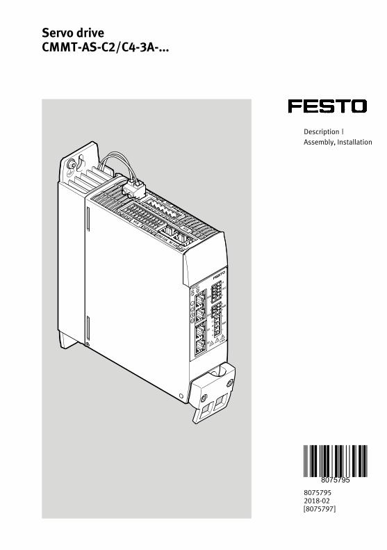
Servo driveCMMT-AS-C2/C4-3A-...
80757952018-02[8075797]
Description |Assembly, Installation

Translation of the original instructions
EnDat®, EtherCAT®, EtherNet/IP®, DR. JOHANNES HEIDENHAIN®, Hiperface®, PI PROFIBUS PROFINET®,PHOENIX CONTACT® are registered trademarks of the respective trademark owners in certain coun-tries.
2 Festo — CMMT-AS-C2/C4-3A-... — 2018-02
3Festo — CMMT-AS-C2/C4-3A-... — 2018-02
1 About this document................................................................................................... 5
1.1 Target group................................................................................................................. 5
1.2 Further applicable documents...................................................................................... 5
1.3 Product variants........................................................................................................... 5
1.4 Product labelling.......................................................................................................... 6
1.5 Specified standards...................................................................................................... 9
2 Safety........................................................................................................................... 9
2.1 Safety instructions........................................................................................................ 9
2.2 Intended use................................................................................................................ 10
2.2.1 Application areas.................................................................................................... 11
2.2.2 Permissible components.........................................................................................11
2.3 Training of skilled personnel........................................................................................ 11
2.4 Approvals and certifications......................................................................................... 11
3 Further information..................................................................................................... 12
4 Service..........................................................................................................................12
5 Product overview......................................................................................................... 12
5.1 Scope of delivery.......................................................................................................... 12
5.2 System structure.......................................................................................................... 12
5.2.1 Product design........................................................................................................14
5.2.2 Overview of connection technology........................................................................ 17
6 Transport and storage................................................................................................. 18
7 Assembly..................................................................................................................... 18
7.1 Mounting distances CMMT-AS-...-3A (1-phase)............................................................ 19
7.2 Installation................................................................................................................... 20
8 Installation.................................................................................................................. 21
8.1 Safety............................................................................................................................ 21
8.2 Residual current device................................................................................................ 22
8.3 Mains fuse.................................................................................................................... 22
8.4 Permissible and impermissible electrical network types................................................24
8.5 Connection of the mains side PE protective conductor.................................................. 27
8.6 Information on EMC-compliant installation................................................................... 28
8.7 Connection examples................................................................................................... 31
8.8 Interfaces..................................................................................................................... 33
8.8.1 [X1A], Inputs and outputs for the higher-order PLC................................................. 33
8.8.2 [X1C], Inputs and outputs to the axle...................................................................... 41
8.8.3 [X2], Sensor interface 1........................................................................................... 43
8.8.4 [X3], Sensor interface 2........................................................................................... 49
8.8.5 [X10], SYNC IN/OUT................................................................................................ 52
8.8.6 [X18], standard Ethernet......................................................................................... 57
8.8.7 [X19], Real-time Ethernet (RTE) port 1 and port 2....................................................59
Table of contents
8.9 Motor connection.......................................................................................................... 60
8.9.1 [X6A], Motor phase connection.............................................................................. 60
8.9.2 [X6B], Motor auxiliary connection.......................................................................... 62
8.9.3 Shield support of the motor cable.......................................................................... 63
8.10 Power and logic voltage supply..................................................................................... 66
8.10.1 [X9A], Power supply and intermediate circuit connection........................................66
8.10.2 [X9B], Connection, braking resistor........................................................................ 67
8.11 Cross wiring...................................................................................................................69
8.11.1 Cross wiring of the I/O signals at the connection [X1A]........................................... 70
8.11.2 Cross wiring of the mains and logic voltage supply................................................ 72
9 Malfunctions................................................................................................................ 77
9.1 Diagnostics via LED....................................................................................................... 77
9.1.1 Device status displays........................................................................................... 78
9.1.2 Interface status [X2], [X3], [X10], [X18]................................................................... 81
9.1.3 Device and interface status EtherCAT.................................................................... 82
9.1.4 Device and interface status ProfiNet...................................................................... 83
9.1.5 Device and interface status EtherNet/IP................................................................ 84
10 Dismounting................................................................................................................. 86
11 Technical data.............................................................................................................. 87
11.1 Technical data product conformity and approvals......................................................... 87
11.2 General technical data...................................................................................................87
11.3 Technical data, electrical............................................................................................... 90
11.3.1 Load and logic voltage supply [X9A]....................................................................... 90
11.3.2 Electrical data for braking resistor (internal/external) [X9B]................................... 93
11.3.3 Power specifications, motor connection [X6A]....................................................... 94
11.3.4 Motor auxiliary connection [X6B]........................................................................... 96
11.3.5 Encoder interfaces [X2], [X3].................................................................................. 97
11.3.6 Inputs, outputs, ready contact at [X1A].................................................................. 102
11.3.7 Inputs and outputs to the axis [X1C]...................................................................... 109
11.3.8 SYNC IN/OUT [X10]................................................................................................ 111
11.3.9 Standard Ethernet [X18], parameterisation interface.............................................. 112
11.3.10 Real-time Ethernet [X19] ([XF1 IN], [XF2 OUT])........................................................ 113
4 Festo — CMMT-AS-C2/C4-3A-... — 2018-02
5Festo — CMMT-AS-C2/C4-3A-... — 2018-02
1 About this document1.1 Target groupThe document is targeted towards individuals who perform assembly and installation and servicework on the product.
1.2 Further applicable documents All available documents for the product è www.festo.com/pk.
The user documentation for the product also includes the following documents:
Designation Table of contents
Instruction manual CMMT-AS-... Instruction manual for assembly, installation,and safety function
Description CMMT-AS-...-SY-... Description for assembly and installation
Descriptions CMMT-AS-... Descriptions on:– Operating modes and operational functions– specifically for each bus protocol/activation:
Device profiles, controller and parameterisa-tion
– Safety function, STO, SBC, SS1
Help for commissioning software Online help for:– Function of the commissioning software– Commissioning and parameterisation of the
CMMT
Tab. 1 User documentation for the product
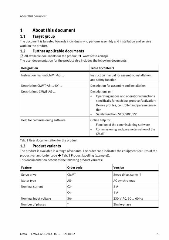
1.3 Product variantsThe product is available in a range of variants. The order code indicates the equipment features of theproduct variant (order code è Tab. 3 Product labelling (example)).This documentation describes the following product variants:
Feature Order code Version
Servo drive CMMT- Servo drive, series T
Motor type AS- AC synchronous
C2- 2 ANominal current
C4- 4 A
Nominal input voltage 3A- 230 V AC, 50 … 60 Hz
Number of phases – Single-phase
About this document
Feature Order code Version
EC- EtherCAT
EP EtherNet/IP
Bus protocol/activation
PN- PROFINET
Safety function S1 Standard safety
Cooling method – Integrated cooling element– Basic type
C..- Customer variant …
Firmware type
S..- Sales variant ... – Basic versionFirmware version
V..- Version …
Certification – CE-compliant basic version
Tab. 2 Product variants CMMT-AS-...-3A (e.g. CMMT-AS-C2-3A-EC-S1)
This documentation refers to the following version:– Servo drive CMMT-AS-...-S1, revision R01 and higher, see product labelling.This is the first available revision.• For later revisions of the product, check whether updated documentation is availableè www.festo.com/pk.
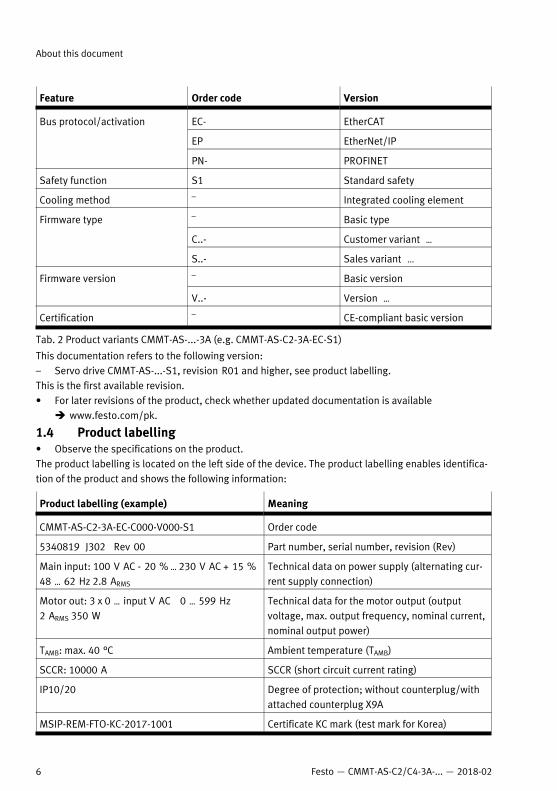
1.4 Product labelling• Observe the specifications on the product.The product labelling is located on the left side of the device. The product labelling enables identifica-tion of the product and shows the following information:
Product labelling (example) Meaning
CMMT-AS-C2-3A-EC-C000-V000-S1 Order code
5340819 J302 Rev 00 Part number, serial number, revision (Rev)
Main input: 100 V AC - 20 % … 230 V AC + 15 %48 … 62 Hz 2.8 ARMS
Technical data on power supply (alternating cur-rent supply connection)
Motor out: 3 x 0 … input V AC 0 … 599 Hz2 ARMS 350 W
Technical data for the motor output (outputvoltage, max. output frequency, nominal current,nominal output power)
TAMB: max. 40 °C Ambient temperature (TAMB)
SCCR: 10000 A SCCR (short circuit current rating)
IP10/20 Degree of protection; without counterplug/withattached counterplug X9A
MSIP-REM-FTO-KC-2017-1001 Certificate KC mark (test mark for Korea)
About this document
6 Festo — CMMT-AS-C2/C4-3A-... — 2018-02
Product labelling (example) Meaning
See manual for internal overload protection andrequired external circuit breaker
Reference to the existing user documentation,which contains information on overload protec-tion and the necessary external circuit breaker.
Data matrix code, 123456789ABC... Product key as a data matrix code and an11-character alphanumeric code
Festo AG & Co. KG Manufacturer
DE-73734 Esslingen Manufacturer’s address
Made in Germany Manufactured in Germany
Tab. 3 Product labelling (example)
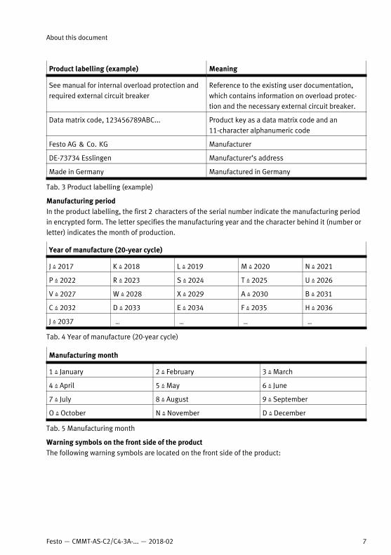
Manufacturing periodIn the product labelling, the first 2 characters of the serial number indicate the manufacturing periodin encrypted form. The letter specifies the manufacturing year and the character behind it (number orletter) indicates the month of production.
Year of manufacture (20-year cycle)
J Z 2017 K Z 2018 L Z 2019 M Z 2020 N Z 2021
P Z 2022 R Z 2023 S Z 2024 T Z 2025 U Z 2026
V Z 2027 W Z 2028 X Z 2029 A Z 2030 B Z 2031
C Z 2032 D Z 2033 E Z 2034 F Z 2035 H Z 2036
J Z 2037 … … … …
Tab. 4 Year of manufacture (20-year cycle)
Manufacturing month
1 Z January 2 Z February 3 Z March
4 Z April 5 Z May 6 Z June
7 Z July 8 Z August 9 Z September
O Z October N Z November D Z December
Tab. 5 Manufacturing month
Warning symbols on the front side of the productThe following warning symbols are located on the front side of the product:
About this document
7Festo — CMMT-AS-C2/C4-3A-... — 2018-02
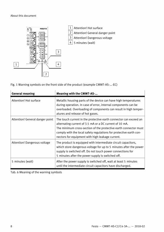
1 Attention! Hot surface
2 Attention! General danger point
3 Attention! Dangerous voltage
4 5 minutes (wait)
Fig. 1 Warning symbols on the front side of the product (example CMMT-AS-...-EC)
General meaning Meaning with the CMMT-AS-...
Attention! Hot surface Metallic housing parts of the device can have high temperaturesduring operation. In case of error, internal components can beoverloaded. Overloading of components can result in high temper-atures and release of hot gases.
Attention! General danger point The touch current in the protective earth connector can exceed analternating current of 3.5 mA or a DC current of 10 mA.The minimum cross-section of the protective earth connector mustcomply with the local safety regulations for protective earth con-nectors for equipment with high leakage current.
Attention! Dangerous voltage The product is equipped with intermediate circuit capacitors,which store dangerous voltage for up to 5 minutes after the powersupply is switched off. Do not touch power connections for5 minutes after the power supply is switched off.
5 minutes (wait) After the power supply is switched off, wait at least 5 minutesuntil the intermediate circuit capacitors have discharged.
Tab. 6 Meaning of the warning symbols
About this document
8 Festo — CMMT-AS-C2/C4-3A-... — 2018-02
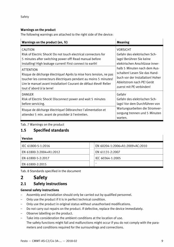
Warnings on the productThe following warnings are attached to the right side of the device:
Warnings on the product (en, fr) Meaning
CAUTIONRisk of Electric Shock! Do not touch electrical connectors for5 minutes after switching power off! Read manual beforeinstalling! High leakage current! First connect to earth!
ATTENTIONRisque de décharge électrique! Après la mise hors tension, ne pastoucher les connecteurs électriques pendant au moins 5 minutes!Lire le manuel avant installation! Courant de défaut élevé! Reliertout d´abord à la terre!
VORSICHTGefahr des elektrischen Sch-lags! Berühren Sie keineelektrischen Anschlüsse inner-halb 5 Minuten nach dem Aus-schalten! Lesen Sie das Hand-buch vor der Installation! HoherAbleitstrom nach PE! Gerätzuerst mit PE verbinden!
DANGERRisk of Electric Shock! Disconnect power and wait 5 minutesbefore servicing.
Risque de décharge électrique! Débranchez l'alimentation etattendez 5 min. avant de procéder à l'entretien.
GefahrGefahr des elektrischen Sch-lags! Vor dem Durchführen vonWartungsarbeiten die Stromver-sorgung trennen und 5 Minutenwarten.
Tab. 7 Warnings on the product
1.5 Specified standards
Version
IEC 61800-5-1:2016 EN 60204-1:2006+A1:2009+AC:2010
EN 61800-3:2004+A1:2012 EN 61131-2:2007
EN 61800-5-2:2017 IEC 60364-1:2005
EN 61800-2:2015 –
Tab. 8 Standards specified in the document
2 Safety2.1 Safety instructionsGeneral safety instructions – Assembly and installation should only be carried out by qualified personnel.– Only use the product if it is in perfect technical condition.– Only use the product in original status without unauthorised modifications.– Do not carry out repairs on the product. If defective, replace the device immediately.– Observe labelling on the product.– Take into consideration the ambient conditions at the location of use.
The safety functions might fail and malfunctions might occur if you do not comply with the para-meters and conditions required for the surroundings and connections.
Safety
9Festo — CMMT-AS-C2/C4-3A-... — 2018-02
– Wear required personal protective equipment during transport and during assembly and disas-sembly of very heavy product versions.
– Never remove or insert a plug connector when powered.– Loosen only the following screws on the product:
– Earthing screw on the cooling element for mounting the PE connection on the mains side– Retaining screws of the shield clamp on the housing front– Only when used in IT networks: screw for connection of the internal mains filter to PE
– Install the product in a suitable control cabinet. The control cabinet requires at least degree ofprotection IP54.
– Operate product only in an installed condition when all required protective measures have beentaken (è EN 60204-1).
– Completely insulate conducting lines on the product. We recommend cable end sleeves withplastic sleeves for wiring power connections.
– Ensure correct earth protection and shield connection.– Prior to commissioning, ensure that the resulting movements of the connected actuators cannot
endanger anyone.– During commissioning: Systematically check all control functions and the communication and sig-
nal interface between controller and drive regulator.– The product is equipped with intermediate circuit capacitors, which store dangerous voltage for
up to 5 minutes after the power supply is switched off. Before working on the product, switch offthe power supply via the master switch and secure it against being switched on again unintention-ally. Before touching the power connections, wait at least 5 minutes.
– Take into consideration the legal regulations for the respective destination.– Keep the documentation throughout the entire product lifecycle.In the event of damage caused by unauthorised manipulation or any use other than that intended, thewarranty is invalidated and the manufacturer is not liable for damages.In the event of damage caused by using unauthorised software or firmware with the device, the war-ranty is invalidated and the manufacturer is not liable for damages.
Safety instructions on the safety functions of the product è textvar object does not exist.
2.2 Intended useThe servo drive CMMT-AS is intended for supply and control of AC servo motors. The integrated elec-tronics permit regulation of torque (current), rotational speed and position. Use exclusively:– in perfect technical condition– in original status without unauthorised modifications; only the extensions described in the docu-
mentation supplied with the product are permitted– within the limits of the product defined by the technical data è 11 Technical data– in an industrial environmentThe safety functions might fail and malfunctions might occur if you do not comply with the parametersand conditions required for the surroundings and connections.
Safety
10 Festo — CMMT-AS-C2/C4-3A-... — 2018-02
Intended use of the safety functions of the product è textvar object does not exist.
2.2.1 Application areasThe device is intended for use in an industrial environment. Outside of industrial environments, meas-ures may need to be implemented for radio interference suppression, e.g. in commercial and mixed-residential areas.The device is intended to be installed in a control cabinet. The control cabinet requires at least degreeof protection IP54.The device can be operated in TN, TT and IT systems if certain requirements are met. Detailed informa-tion on allowed and prohibited electrical network typesè 8.4 Permissible and impermissible electrical network types.2.2.2 Permissible componentsIf holding brakes and clamping units without certification are used, the suitability for the relatedsafety-oriented application must be determined through a risk assessment.The motors must fulfil the requirements of EN 61800-5-2 appendix D.3.5 and D.3.6 and ofEN 60204-1. Motors approved or specified by Festo for the CMMT-AS fulfil the requirements.The motor cables and brake lines must fulfil the requirements of EN 61800-5-2 appendix D.3.1 and ofEN 60204-1. Motor cables and brake lines approved by Festo for the CMMT-AS fulfil the requirements.
2.3 Training of skilled personnelThe product may be installed and placed in operation only by a qualified electro technician, who isfamiliar with the topics:– installation and operation of electrical control systems– applicable regulations for operating safety-engineering systemsWork on safety-related systems may only be carried out by qualified personnel trained in safety engin-eering.
2.4 Approvals and certificationsThe product has the CE marking. Guidelines seeè 11.1 Technical data product conformity and approvals.The product-relevant EC directives and standards are listed in the declaration of conformityè www.festo.com/sp.The product is a safety device in accordance with the Machinery Directive. Safety-oriented standardsand test values that the product complies with and fulfils è textvar object does not exist, technicaldata, safety engineering. Observe that compliance with the named standards is limited to the CMMT-AS-...-S1.Certain configurations of the product have been certified by Underwriters Laboratories Inc. (UL) for theUSA and Canada.These configurations bear the following mark:
Fig. 2
Safety
11Festo — CMMT-AS-C2/C4-3A-... — 2018-02
UL Recognized Component Mark for Canada and the United States.Only for connection to a NEC/CEC Class 2 supply.Raccorder Uniquement a un circuit de NEC/CEC Classe 2.During installation and operation of this product, comply with all safety requirements, statutes, codes,rules and standards relevant for the product, such as National Electrical Code (USA), Canadian Elec-trical Code (Canada), regulations of the US federal agency OSHA. When selecting the circuit breaker,comply with the maximum permissible electrical protection for UL.
3 Further information– Accessories è www.festo.com/catalogue– Spare parts è www.festo.com/spareparts.– All available documents for the product and current versions of the firmware and commissioning
software è www.festo.com/sp.
4 ServiceContact your regional Festo contact person if you have technical questions è www.festo.com.
5 Product overview5.1 Scope of delivery
Component Number
Servo drive CMMT-AS-... 1
Instruction manual CMMT-AS-... 1
Tab. 9 Scope of delivery
Available as accessories are, for example:– Plug connector set for single wiring NEKM-C6-...-S– Plug connector set for double wiring NEKM-C6-...-D– External braking resistor CACR-...– Motor cable NEBM-... , e.g. for the motor series EMMS-AS, EMME-AS and EMMT-AS– Sensor line, e.g. for the motor series EMMS-AS, EMME-AS and EMMT-AS– Patch line NEBC-..., e.g. for linkage of the RTE interface [X19A/B] – Display and operating unit CDSB-...– Mains filter
Up-to-date information on the accessories è www.festo.com/catalogue.
5.2 System structureThe servo drive CMMT-AS is a 1-axis servo drive. Depending on the product variant, the following com-ponents, which are necessary for standard applications, are integrated into the device or into the cool-ing profile of the device:– Mains filter (guarantees immunity to interference and limits line-bound emitted interference)– Electronics for intermediate circuit voltage processing– Output stage (for motor activation)
Further information
12 Festo — CMMT-AS-C2/C4-3A-... — 2018-02
– Braking resistor (integrated into the cooling element)– Brake chopper (switches the braking resistor in the intermediate circuit, as needed)– Temperature sensors (for monitoring the temperature of the power module and of the air in the
device)– Fan (dependent on the product variant in the cooling profile)The device has separate connections for logic and load voltage supply. The load voltage supply comesdirectly from the low voltage network. The logic supply must be provided through a PELV power sup-ply unit (+24 V DC).The servo drive offers the possibility to connect 2 sensors. In addition, the device has 1 switching out-put for direct connection of the holding brake in the motor and 1 output for control of an externalclamping unit.An external braking resistor can be connected instead of the internal braking resistor, if necessary.An Ethernet interface is available for parameterisation through a PC. The type of activations dependson the product design (e.g. over bus/network, over EtherCAT, EtherNet/IP or PROFINET).If required, the CDSB display and operating unit can be plugged in on top of the front side of thedevice. The CDSB displays, for example, diagnostic information as well as setpoint and actual valuesin plain text and permits updating of parameter record and firmware.For operation of several servo drives in a device compound, the intermediate circuits of severaldevices can be coupled and the power supplies and I/O signals of the devices can be linked throughcross-wiring. The intermediate circuit coupling can increase the energy efficiency of the device com-pound.
Festo recommends use of servo motors, electromechanical drives, lines and accessories from theFesto accessory programme.
Product overview
13Festo — CMMT-AS-C2/C4-3A-... — 2018-02
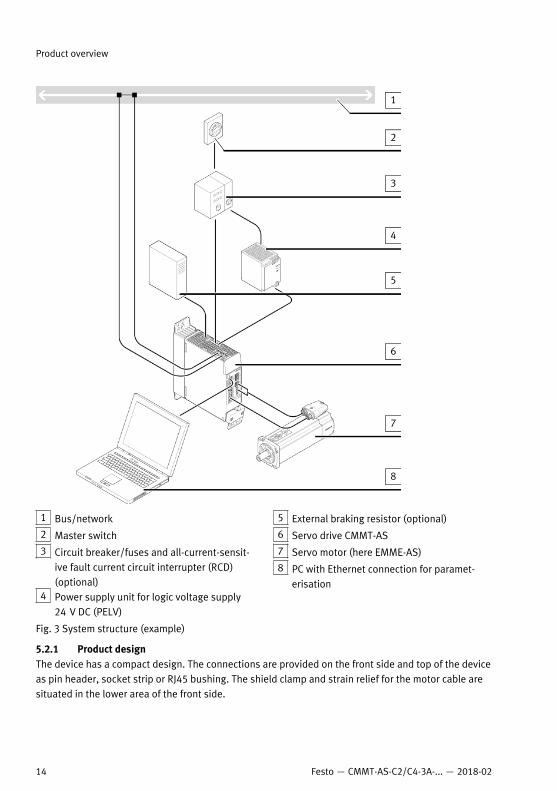
1 Bus/network
2 Master switch
3 Circuit breaker/fuses and all-current-sensit-ive fault current circuit interrupter (RCD)(optional)
4 Power supply unit for logic voltage supply24 V DC (PELV)
5 External braking resistor (optional)
6 Servo drive CMMT-AS
7 Servo motor (here EMME-AS)
8 PC with Ethernet connection for paramet-erisation
Fig. 3 System structure (example)
5.2.1 Product designThe device has a compact design. The connections are provided on the front side and top of the deviceas pin header, socket strip or RJ45 bushing. The shield clamp and strain relief for the motor cable aresituated in the lower area of the front side.
Product overview
14 Festo — CMMT-AS-C2/C4-3A-... — 2018-02
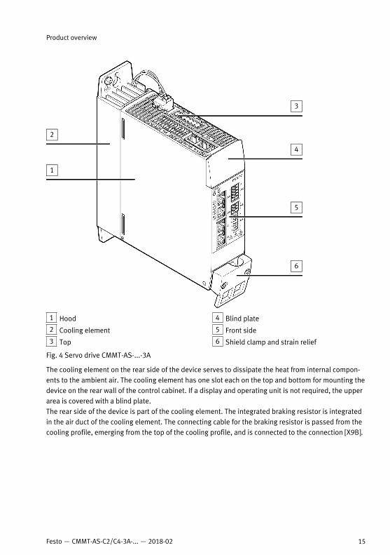
1 Hood
2 Cooling element
3 Top
4 Blind plate
5 Front side
6 Shield clamp and strain relief
Fig. 4 Servo drive CMMT-AS-...-3A
The cooling element on the rear side of the device serves to dissipate the heat from internal compon-ents to the ambient air. The cooling element has one slot each on the top and bottom for mounting thedevice on the rear wall of the control cabinet. If a display and operating unit is not required, the upperarea is covered with a blind plate.The rear side of the device is part of the cooling element. The integrated braking resistor is integratedin the air duct of the cooling element. The connecting cable for the braking resistor is passed from thecooling profile, emerging from the top of the cooling profile, and is connected to the connection [X9B].
Product overview
15Festo — CMMT-AS-C2/C4-3A-... — 2018-02
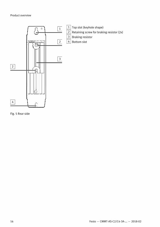
1 Top slot (keyhole shape)
2 Retaining screw for braking resistor (2x)
3 Braking resistor
4 Bottom slot
Fig. 5 Rear side
Product overview
16 Festo — CMMT-AS-C2/C4-3A-... — 2018-02
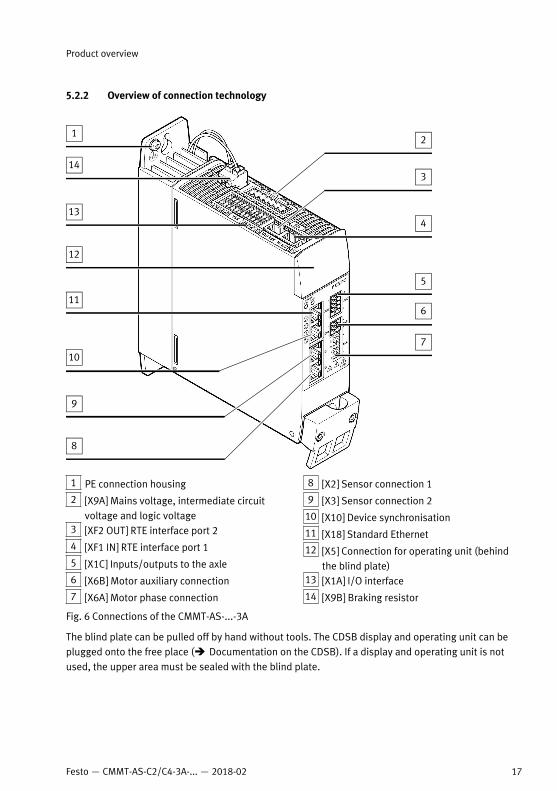
5.2.2 Overview of connection technology
1 PE connection housing
2 [X9A] Mains voltage, intermediate circuitvoltage and logic voltage
3 [XF2 OUT] RTE interface port 2
4 [XF1 IN] RTE interface port 1
5 [X1C] Inputs/outputs to the axle
6 [X6B] Motor auxiliary connection
7 [X6A] Motor phase connection
8 [X2] Sensor connection 1
9 [X3] Sensor connection 2
10 [X10] Device synchronisation
11 [X18] Standard Ethernet
12 [X5] Connection for operating unit (behindthe blind plate)
13 [X1A] I/O interface
14 [X9B] Braking resistor
Fig. 6 Connections of the CMMT-AS-...-3A
The blind plate can be pulled off by hand without tools. The CDSB display and operating unit can beplugged onto the free place (è Documentation on the CDSB). If a display and operating unit is notused, the upper area must be sealed with the blind plate.
Product overview
17Festo — CMMT-AS-C2/C4-3A-... — 2018-02
6 Transport and storage– Protect the product during transport and storage from excessive stress factors. Excessive stress
factors include: – mechanical stresses– impermissible temperatures– moisture– aggressive atmospheres
– Store and transport the product in its original packaging. The original packaging offers sufficientprotection from typical stresses.
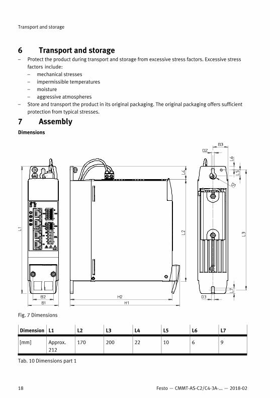
7 AssemblyDimensions
Fig. 7 Dimensions
Dimension L1 L2 L3 L4 L5 L6 L7
[mm] Approx.212
170 200 22 10 6 9
Tab. 10 Dimensions part 1
Transport and storage
18 Festo — CMMT-AS-C2/C4-3A-... — 2018-02
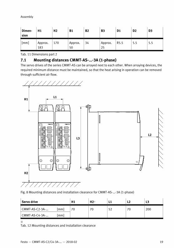
Dimen-sion
H1 H2 B1 B2 B3 D1 D2 D3
[mm] Approx.183
170 Approx.50
34 Approx.25
R5.5 5.5 5.5
Tab. 11 Dimensions part 2
7.1 Mounting distances CMMT-AS-...-3A (1-phase)The servo drives of the series CMMT-AS can be arrayed next to each other. When arraying devices, therequired minimum distance must be maintained, so that the heat arising in operation can be removedthrough sufficient air flow.
Fig. 8 Mounting distances and installation clearance for CMMT-AS-...-3A (1-phase)
Servo drive H1 H21) L1 L2 L3
CMMT-AS-C2-3A-... [mm]
CMMT-AS-C4-3A-... [mm]
70 70 52 70 200
1)
Tab. 12 Mounting distances and installation clearance
Assembly
19Festo — CMMT-AS-C2/C4-3A-... — 2018-02
Servo drive H1 H21) L1 L2 L3
The required minimum lateral distance from neighbouring CMMT-AS devices is thus 2 mm(52 mm – 50 mm).For adjacent third-party devices, Festo recommends a distance of at least 10 mm (surface temperat-ure of third-party device max. 40 °C). The double counterplug for cross wiring of the connection [X9A]projects approx. 6 … 7 mm over the right side of the device. But this is not an obstacle for arrayingadditional CMMT-AS.
7.2 InstallationThe servo drive CMMT-AS is intended to be installed in a control cabinet.The cooling element of the device has one slot each on the top and on the bottom. The device isscrewed vertically and flat to the mounting surface using the two slots.
Assembly instructions– Use a control cabinet with at least degree of protection IP54.– Always install device vertically in the control cabinet (mains supply lines [X9A] point upwards).– Screw device flat to a sufficiently stable mounting surface so that a good heat transfer from the
cooling element to the mounting surface is ensured (e.g. to the rear wall of the control cabinet). – Maintain minimum distances and installation clearance to ensure sufficient air flow. The surround-
ing air in the control cabinet must be able to flow through the device without hindrance.– Take into account the required clearance for the wiring (connecting cables of the device are
guided in from above and from the front).– Do not mount any temperature-sensitive components near the device. The device can become
very hot in operation (switch-off temperature of the temperature monitoring è Technical data).– When assembling several devices in a device compound, consider general rules for cross-wiring.
For intermediate circuit coupling, devices with greater power use must be placed closer to themains supply.
For assembling to the rear panel of the control cabinet, the cooling element of the servo drive has aslot on top in the shape of a keyhole and on the bottom in the shape of a simple slot.
Assembly of the servo drive
WARNING!
Danger of burns through hot escaping gases and hot surfaces.In case of error, incorrect wiring or incorrect polarity of the connections [X9A], [X9B] and [X6A], internalcomponents can be overloaded. High temperatures can develop and hot gases can be released.• Have an authorised electrician perform the installation according to the documentation.
WARNING!
Danger of burns from hot housing surfaces.Metallic housing parts can accept high temperatures in operation. In particular, the braking resistorinstalled in the profile on the back side can become very hot.Contact with metal housing parts can cause burn injuries.• Do not touch metallic housing parts.• After the power supply is switched off, let the device cool off to room temperature.
Assembly
20 Festo — CMMT-AS-C2/C4-3A-... — 2018-02
• Fasten the servo drive to the rear wall of the control cabinet with suitable screws while complyingwith the assembly instructions.
8 Installation8.1 Safety
WARNING!
Risk of injury from electric shock.Contact with conducting parts at the power connections [X6A], [X9A] and [X9B] can result in severeinjuries or death.• Do not pull power supply connectors when powered.• Before touching, wait at least 5 minutes until the intermediate circuit has discharged.
WARNING!
Risk of injury from electric shock.The leakage current of the device to earth (PE) is > 3.5 mA AC or 10 mA DC. Touching the device ifthere is a fault can result in serious injuries or death.Before commissioning, also for brief measuring and test purposes:• Connect PE connection to the mains side at the following positions:
– Protective conductor connection (earthing screw) of the housing– Pin PE of the connection [X9A] (power supply)
The cross section of the protective conductor must equal at least the cross section of the out-er conductor L [X9A].
• Connect motor cable to the connection [X6A] and the shield of the motor cable on the front side toPE via the shield clamp of the servo drive.
• Connect all additional PE protective conductors of the connections used.• Observe the regulations of EN 60204-1 for the protective earthing.
WARNING!
Danger of burns through hot escaping gases and hot surfaces.In case of error, incorrect wiring or incorrect polarity of the connections [X9A], [X9B] and [X6A], internalcomponents can be overloaded. High temperatures can develop and hot gases can be released.• Have an authorised electrician perform the installation according to the documentation.
WARNING!
Risk of injury from electric shock in case of incomplete insulation at the power connections [X6A],[X9A] and [X9B].Before operating, plugging in or unplugging the display and operating unit CDSB or a connector from ahot-plug-capable interface, the following points must be fulfilled: • The conducting lines at the device are completely insulated.• The protective earth (PE) and the shield connection are correctly connected to the device.• The housing is free of damage.
Installation
21Festo — CMMT-AS-C2/C4-3A-... — 2018-02
8.2 Residual current deviceWARNING!
Risk of injury from electric shock.This product can cause a DC current in the residual-current conductor in case of error. In cases where aresidual current device (RCD) or a residual current monitor (RCM) is used to protect against direct orindirect contact, only the type B kind of RCD or RCM is permitted on the power supply side of thisproduct.
The touch current in the protective earth connector can exceed an alternating current of 3.5 mA or aDC current of 10 mA. The minimum cross-section of the protective earth connector must comply withthe local safety regulations for protective earth connectors for equipment with high leakage current.A residual current circuit breaker with 30 mA tripping current can be suitable for a separately wiredCMMT-AS servo drive, depending on configuration. As a rule, residual current protective devices with arated leakage current > 30 mA are required for a device compound consisting of several servo drives.Festo recommends use of a residual current protective device with trigger delay, as high current leak-age results when switched on. Residual current devices with trigger delay prevent unintended trigger-ing when switched on.
8.3 Mains fuseThe CMMT-AS has no integrated fuse at the mains input or in the intermediate circuit. An external fuseat the mains supply of the device is required. Festo recommends the use of a line safety switch (circuitbreaker). A device compound coupled in the intermediate circuit must be protected through a commonline safety switch. Different requirements for line safety switches are specified for the UL approval andthe CE approval.• Use only line safety switches with corresponding approval and the specifications and fuse protec-
tions named in the following.
Line safety switch (circuit breaker)
Requirement Specification
Short circuit currentrating SCCR
[kA] Min. 10
IPEAK (peak let through) [kA] Max. 7.5
Rated voltage [V AC] Min. 230
Overvoltage category III
Degree of contamina-tion
2
Characteristic C
Tab. 13 Requirements for the line safety switch
The line safety switch is used for line protection. The rated current of the line safety switch must beless than or equal to the permissible current carrying capacity of the selected conductor cross section.
Installation
22 Festo — CMMT-AS-C2/C4-3A-... — 2018-02
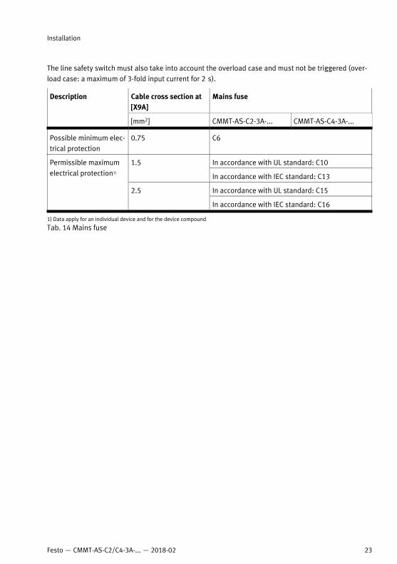
The line safety switch must also take into account the overload case and must not be triggered (over-load case: a maximum of 3-fold input current for 2 s).
Cable cross section at[X9A]
Mains fuseDescription
[mm2] CMMT-AS-C2-3A-... CMMT-AS-C4-3A-...
Possible minimum elec-trical protection
0.75 C6
In accordance with UL standard: C101.5
In accordance with IEC standard: C13
In accordance with UL standard: C15
Permissible maximumelectrical protection1)
2.5
In accordance with IEC standard: C16
1) Data apply for an individual device and for the device compound
Tab. 14 Mains fuse
Installation
23Festo — CMMT-AS-C2/C4-3A-... — 2018-02
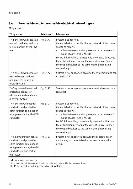
8.4 Permissible and impermissible electrical network typesTN systems
TN systems Reference1) Information
TN-S system with separateneutral conductor and pro-tective earth in overall sys-tem
Fig. 31A1 System is supported.Connect device to the distribution network of the currentsource as follows:– either between a mains phase and N or between 2
mains phases (230 V AC, LL)For DC link coupling, connect only one device directly tothe distribution network of the current source. Connectthe coupled devices to the same mains phase usingcross wiring.2)
TN-S system with separateearthed outer conductorand protective earth inoverall system
Fig. 31A2 System is not supported because the system voltage canexceed 300 V!
TN-S system with earthedprotective conductorwithout neutral conductorin overall system
Fig. 31A3 System is not supported because a neutral conductor isrequired!
TN-C system with neutralconductor and protectiveearth function combined ina single conductor, the PENconductor
Fig. 31C System is supported.Connect device to the distribution network of the currentsource as follows:– either between a mains phase and N or between 2
mains phases (230 V AC, LL)For DC link coupling, connect only one device directly tothe distribution network of the current source. Connectthe coupled devices to the same mains phase usingcross wiring.2)
TN-C-S system with neutralconductor and protectiveearth function combined ina single conductor, the PENconductor, in one part ofthe system
Fig. 31B1 System is not supported because the separate N con-ductor may not be suitable for the load currents thatoccur.
1) è IEC 60364-1, chapter 312.2.2) For cross wiring, only 1 master switch and 1 circuit breaker is allowed for the compound device.
Tab. 15 Permissible and impermissible TN systems
Installation
24 Festo — CMMT-AS-C2/C4-3A-... — 2018-02

TT system
TT system Reference1) Information
TT system with separateneutral conductor and pro-tective earth in the samesystem. The N conductor is connec-ted directly to the currentsource.
Fig. 31F1 System is supported.Connect device to the distribution network of the currentsource as follows:– either between a mains phase and N or between 2
mains phases (230 V AC, LL)For DC link coupling, connect only one device directly tothe distribution network of the current source. Connectthe coupled devices to the same mains phase usingcross wiring.2)
1) è IEC 60364-1, chapter 312.2.2) For cross wiring, only one master switch and one circuit breaker is allowed for the compound device.
Tab. 16 TT system
IT system
IT system Reference1) Information
IT system with insulation ofactive parts separated fromprotective earth or connec-ted via high impedance.The exposed conductiveparts are connected to alocal earth.
Fig. 31G1 System is supported. – Connect device to the distribution network of the
current source between a mains phase and N.A device or compound device must not be connectedbetween 2 mains phases.– The permissible system voltage of the CMMT-AS is
300 V in accordance with IEC 61800-5-1. Observethe restrictions set out in IEC 61800-5-1 when oper-ating the CMMT-AS in an IT network!
– Use insulation monitoring system so that insulationfaults can be detected immediately (earth-leakagemonitor).
– Interrupt the internal connection of the internalmains filter to PEè Interrupting the connection of the internal mainsfilter to PE (for IT networks only).
– Use external filter measures that ensure CE conform-ity.
For DC link coupling, connect only one device directly tothe distribution network of the current source. Connectthe coupled devices to the same mains phase usingcross wiring.
1) è IEC 60364-1, chapter 312.2.
Tab. 17 IT system
Installation
25Festo — CMMT-AS-C2/C4-3A-... — 2018-02
After removing the connection of the internal mains filter to PE, the device is not classified in respectof emitted interference in accordance with EN 61800-3. External filter measures are required.When operating servo drives in IT networks, the distributor must provide an EMC concept for the over-all system.This comprises as a minimum:– A concept for feeding the converter leakage currents back into the converter intermediate circuit
(Y capacitors to the intermediate circuit)– Use of external filter measures such as mains filter and converter output filter
Earth-leakage monitorFor IT systems, an earth-leakage monitor is required so that an insulation fault between the mainsphase and PE can be detected immediately. An insulation fault must be rectified immediately afterdetection.
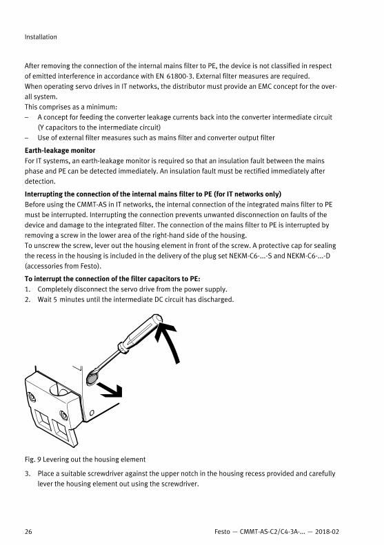
Interrupting the connection of the internal mains filter to PE (for IT networks only)Before using the CMMT-AS in IT networks, the internal connection of the integrated mains filter to PEmust be interrupted. Interrupting the connection prevents unwanted disconnection on faults of thedevice and damage to the integrated filter. The connection of the mains filter to PE is interrupted byremoving a screw in the lower area of the right-hand side of the housing.To unscrew the screw, lever out the housing element in front of the screw. A protective cap for sealingthe recess in the housing is included in the delivery of the plug set NEKM-C6-...-S and NEKM-C6-...-D(accessories from Festo).
To interrupt the connection of the filter capacitors to PE:1. Completely disconnect the servo drive from the power supply.2. Wait 5 minutes until the intermediate DC circuit has discharged.
Fig. 9 Levering out the housing element
3. Place a suitable screwdriver against the upper notch in the housing recess provided and carefullylever the housing element out using the screwdriver.
Installation
26 Festo — CMMT-AS-C2/C4-3A-... — 2018-02
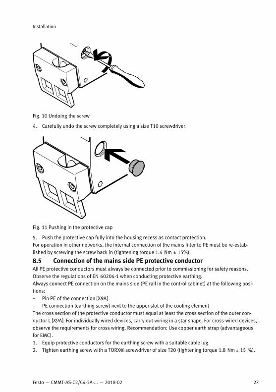
Fig. 10 Undoing the screw
4. Carefully undo the screw completely using a size T10 screwdriver.
Fig. 11 Pushing in the protective cap
5. Push the protective cap fully into the housing recess as contact protection.For operation in other networks, the internal connection of the mains filter to PE must be re-estab-lished by screwing the screw back in (tightening torque 1.4 Nm ± 15%).
8.5 Connection of the mains side PE protective conductorAll PE protective conductors must always be connected prior to commissioning for safety reasons.Observe the regulations of EN 60204-1 when conducting protective earthing.Always connect PE connection on the mains side (PE rail in the control cabinet) at the following posi-tions:– Pin PE of the connection [X9A]– PE connection (earthing screw) next to the upper slot of the cooling elementThe cross section of the protective conductor must equal at least the cross section of the outer con-ductor L [X9A]. For individually wired devices, carry out wiring in a star shape. For cross-wired devices,observe the requirements for cross wiring. Recommendation: Use copper earth strap (advantageousfor EMC).1. Equip protective conductors for the earthing screw with a suitable cable lug.2. Tighten earthing screw with a TORX® screwdriver of size T20 (tightening torque 1.8 Nm ± 15 %).
Installation
27Festo — CMMT-AS-C2/C4-3A-... — 2018-02
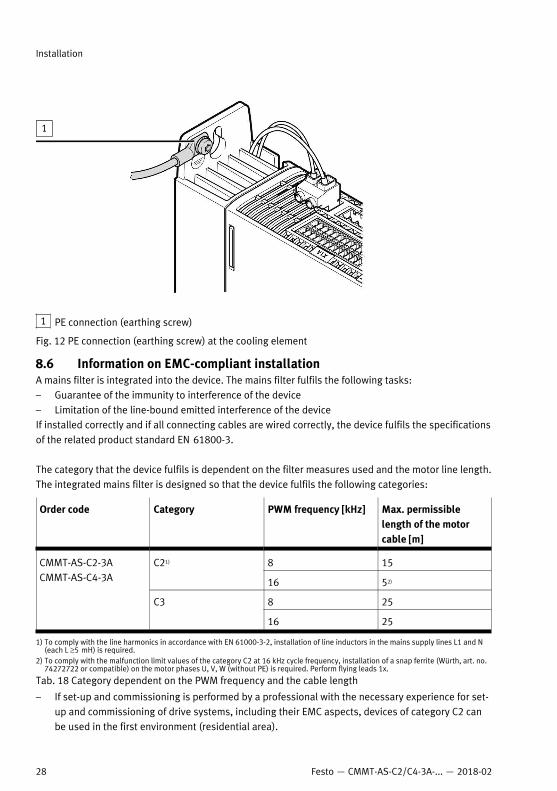
1 PE connection (earthing screw)
Fig. 12 PE connection (earthing screw) at the cooling element
8.6 Information on EMC-compliant installationA mains filter is integrated into the device. The mains filter fulfils the following tasks:– Guarantee of the immunity to interference of the device– Limitation of the line-bound emitted interference of the deviceIf installed correctly and if all connecting cables are wired correctly, the device fulfils the specificationsof the related product standard EN 61800-3.
The category that the device fulfils is dependent on the filter measures used and the motor line length.The integrated mains filter is designed so that the device fulfils the following categories:
Order code Category PWM frequency [kHz] Max. permissiblelength of the motorcable [m]
8 15C21)
16 52)
8 25
CMMT-AS-C2-3ACMMT-AS-C4-3A
C3
16 25
1) To comply with the line harmonics in accordance with EN 61000-3-2, installation of line inductors in the mains supply lines L1 and N(each L ³5 mH) is required.
2) To comply with the malfunction limit values of the category C2 at 16 kHz cycle frequency, installation of a snap ferrite (Würth, art. no.74272722 or compatible) on the motor phases U, V, W (without PE) is required. Perform flying leads 1x.
Tab. 18 Category dependent on the PWM frequency and the cable length
– If set-up and commissioning is performed by a professional with the necessary experience for set-up and commissioning of drive systems, including their EMC aspects, devices of category C2 canbe used in the first environment (residential area).
Installation
28 Festo — CMMT-AS-C2/C4-3A-... — 2018-02
– For operation of devices of category C2, limit values for harmonic currents apply for the mainssupply (EN 61000-3-2 or EN 61000-3-12). Please check whether this is the case for your facil-ity/system. As a rule, compliance with the limit values for harmonic currents requires the use ofexternal filter measures, e.g. installation of a series line inductor.
– Devices of category C3 are intended only for use in the second environment (industrial environ-ment). Use in the first environment is not permitted.
This product can generate high frequency malfunctions, which may make it necessary to implementinterference suppression measures in residential areas.For additional information on EMC-appropriate installation è textvar object does not exist.
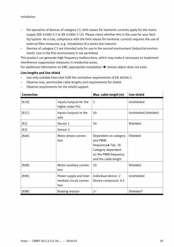
Line lengths and line shield– Use only suitable lines that fulfil the normative requirements of EN 60204-1.– Observe max. permissible cable lengths and requirements for shield.– Observe requirements for the shield support.
Connection Max. cable length [m] Line shield
[X1A] Inputs/outputs for thehigher-order PLC
3 Unshielded
[X1C] Inputs/outputs to theaxle
50 Unshielded/shielded1)
[X2] Sensor 1
[X3] Sensor 2
50 Shielded
[X6A] Motor phase connec-tion
Dependent on categoryand PWMfrequencyè Tab. 18Category dependenton the PWM frequencyand the cable length
Shielded
[X6B] Motor auxiliary connec-tion
50 Shielded
[X9A] Power supply and inter-mediate circuit connec-tion
Individual device: 2Device compound: 0.5
Unshielded
[X9B] Braking resistor 22) Shielded2)
Installation
29Festo — CMMT-AS-C2/C4-3A-... — 2018-02
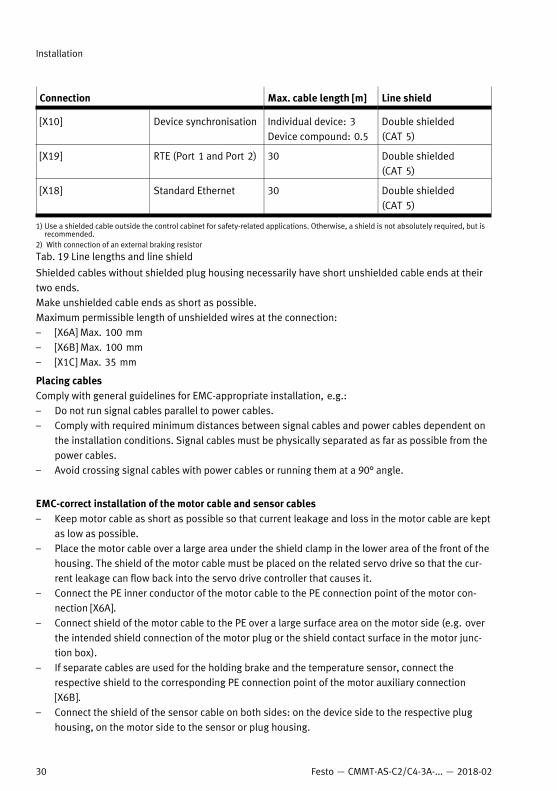
Connection Max. cable length [m] Line shield
[X10] Device synchronisation Individual device: 3Device compound: 0.5
Double shielded(CAT 5)
[X19] RTE (Port 1 and Port 2) 30 Double shielded(CAT 5)
[X18] Standard Ethernet 30 Double shielded(CAT 5)
1) Use a shielded cable outside the control cabinet for safety-related applications. Otherwise, a shield is not absolutely required, but isrecommended.
2) With connection of an external braking resistor
Tab. 19 Line lengths and line shield
Shielded cables without shielded plug housing necessarily have short unshielded cable ends at theirtwo ends.Make unshielded cable ends as short as possible. Maximum permissible length of unshielded wires at the connection:– [X6A] Max. 100 mm– [X6B] Max. 100 mm– [X1C] Max. 35 mm
Placing cablesComply with general guidelines for EMC-appropriate installation, e.g.:– Do not run signal cables parallel to power cables.– Comply with required minimum distances between signal cables and power cables dependent on
the installation conditions. Signal cables must be physically separated as far as possible from thepower cables.
– Avoid crossing signal cables with power cables or running them at a 90° angle.
EMC-correct installation of the motor cable and sensor cables– Keep motor cable as short as possible so that current leakage and loss in the motor cable are kept
as low as possible.– Place the motor cable over a large area under the shield clamp in the lower area of the front of the
housing. The shield of the motor cable must be placed on the related servo drive so that the cur-rent leakage can flow back into the servo drive controller that causes it.
– Connect the PE inner conductor of the motor cable to the PE connection point of the motor con-nection [X6A].
– Connect shield of the motor cable to the PE over a large surface area on the motor side (e.g. overthe intended shield connection of the motor plug or the shield contact surface in the motor junc-tion box).
– If separate cables are used for the holding brake and the temperature sensor, connect therespective shield to the corresponding PE connection point of the motor auxiliary connection[X6B].
– Connect the shield of the sensor cable on both sides: on the device side to the respective plughousing, on the motor side to the sensor or plug housing.
Installation
30 Festo — CMMT-AS-C2/C4-3A-... — 2018-02
– Guide the signal cables [X2], [X3], [X10], [X1C] and [X6B] downward and relieve strain with cablebinders at the cutouts of the shield clamp of the drive controller.
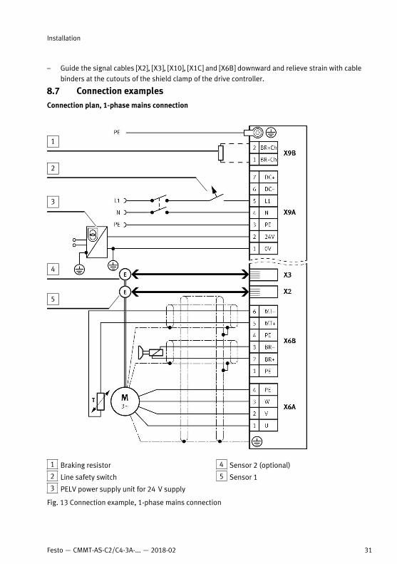
8.7 Connection examplesConnection plan, 1-phase mains connection
1 Braking resistor
2 Line safety switch
3 PELV power supply unit for 24 V supply
4 Sensor 2 (optional)
5 Sensor 1
Fig. 13 Connection example, 1-phase mains connection
Installation
31Festo — CMMT-AS-C2/C4-3A-... — 2018-02

Connection plan, 2-phase mains connection
NOTICE!
Damage to the servo drive with 2-phase connection to a low voltage network with a star voltage of230 V.A low voltage network common in Europe with a nominal star voltage value of 230 V has an inter-linked voltage of approx. 400 V between the 2 phases.• Do not connect a servo drive to 2 phases of the low voltage mains common in Europe.• Comply with the maximum permissible voltage between the phases.
Installation
32 Festo — CMMT-AS-C2/C4-3A-... — 2018-02
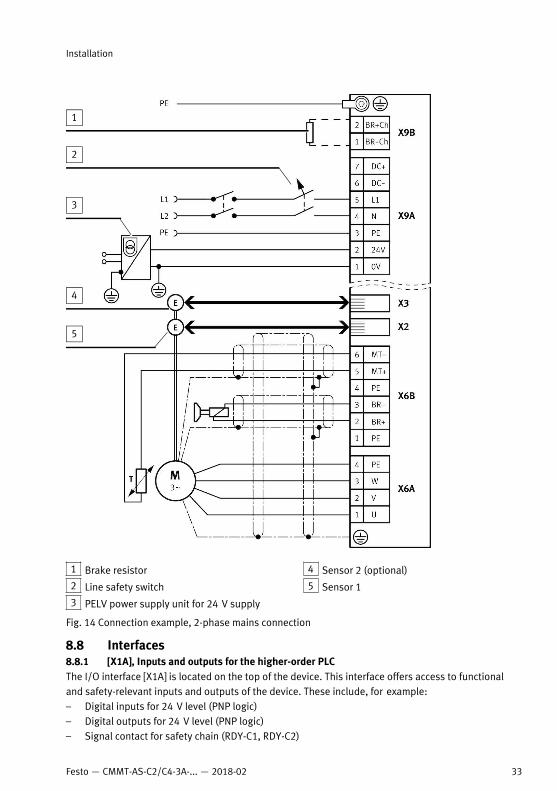
1 Brake resistor
2 Line safety switch
3 PELV power supply unit for 24 V supply
4 Sensor 2 (optional)
5 Sensor 1
Fig. 14 Connection example, 2-phase mains connection
8.8 Interfaces8.8.1 [X1A], Inputs and outputs for the higher-order PLCThe I/O interface [X1A] is located on the top of the device. This interface offers access to functionaland safety-relevant inputs and outputs of the device. These include, for example:– Digital inputs for 24 V level (PNP logic)– Digital outputs for 24 V level (PNP logic)– Signal contact for safety chain (RDY-C1, RDY-C2)
Installation
33Festo — CMMT-AS-C2/C4-3A-... — 2018-02
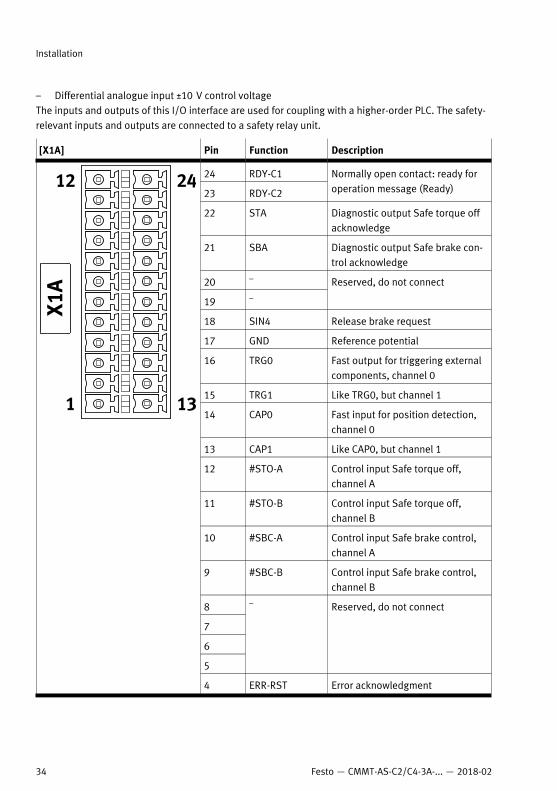
– Differential analogue input ±10 V control voltageThe inputs and outputs of this I/O interface are used for coupling with a higher-order PLC. The safety-relevant inputs and outputs are connected to a safety relay unit.
[X1A] Pin Function Description
24 RDY-C1
23 RDY-C2
Normally open contact: ready foroperation message (Ready)
22 STA Diagnostic output Safe torque offacknowledge
21 SBA Diagnostic output Safe brake con-trol acknowledge
20 –
19 –
Reserved, do not connect
18 SIN4 Release brake request
17 GND Reference potential
16 TRG0 Fast output for triggering externalcomponents, channel 0
15 TRG1 Like TRG0, but channel 1
14 CAP0 Fast input for position detection,channel 0
13 CAP1 Like CAP0, but channel 1
12 #STO-A Control input Safe torque off,channel A
11 #STO-B Control input Safe torque off,channel B
10 #SBC-A Control input Safe brake control,channel A
9 #SBC-B Control input Safe brake control,channel B
8
7
6
5
– Reserved, do not connect
4 ERR-RST Error acknowledgment
Installation
34 Festo — CMMT-AS-C2/C4-3A-... — 2018-02
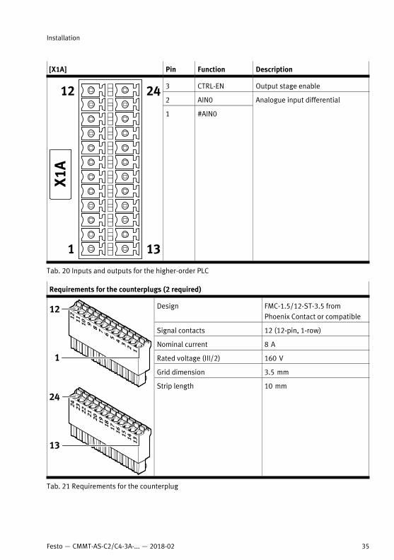
[X1A] Pin Function Description
3 CTRL-EN Output stage enable
2 AIN0
1 #AIN0
Analogue input differential
Tab. 20 Inputs and outputs for the higher-order PLC
Requirements for the counterplugs (2 required)
Design FMC-1.5/12-ST-3.5 fromPhoenix Contact or compatible
Signal contacts 12 (12-pin, 1-row)
Nominal current 8 A
Rated voltage (III/2) 160 V
Grid dimension 3.5 mm
Strip length 10 mm
Tab. 21 Requirements for the counterplug
Installation
35Festo — CMMT-AS-C2/C4-3A-... — 2018-02
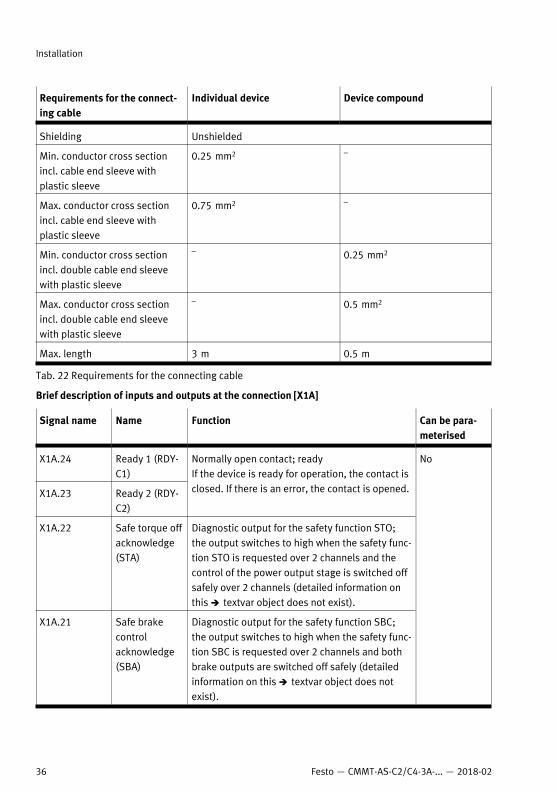
Requirements for the connect-ing cable
Individual device Device compound
Shielding Unshielded
Min. conductor cross sectionincl. cable end sleeve withplastic sleeve
0.25 mm2 –
Max. conductor cross sectionincl. cable end sleeve withplastic sleeve
0.75 mm2 –
Min. conductor cross sectionincl. double cable end sleevewith plastic sleeve
– 0.25 mm2
Max. conductor cross sectionincl. double cable end sleevewith plastic sleeve
– 0.5 mm2
Max. length 3 m 0.5 m
Tab. 22 Requirements for the connecting cable
Brief description of inputs and outputs at the connection [X1A]
Signal name Name Function Can be para-meterised
X1A.24 Ready 1 (RDY-C1)
X1A.23 Ready 2 (RDY-C2)
Normally open contact; readyIf the device is ready for operation, the contact isclosed. If there is an error, the contact is opened.
X1A.22 Safe torque offacknowledge(STA)
Diagnostic output for the safety function STO;the output switches to high when the safety func-tion STO is requested over 2 channels and thecontrol of the power output stage is switched offsafely over 2 channels (detailed information onthis è textvar object does not exist).
X1A.21 Safe brakecontrolacknowledge(SBA)
Diagnostic output for the safety function SBC;the output switches to high when the safety func-tion SBC is requested over 2 channels and bothbrake outputs are switched off safely (detailedinformation on this è textvar object does notexist).
No
Installation
36 Festo — CMMT-AS-C2/C4-3A-... — 2018-02
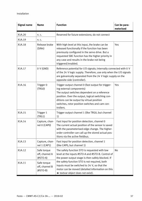
Signal name Name Function Can be para-meterised
X1A.20 n. c.
X1A.19 n. c.
Reserved for future extensions; do not connect
X1A.18 Release brake(SIN4)
With high level at this input, the brake can bereleased functionally if the function has beenpreviously configured in the servo drive. But arequested SBC function has the higher priority inany case and results in the brake not beingtriggered/enabled.
Yes
X1A.17 0 V (GND) Reference potential for I/O signals; internally connected with 0 Vof the 24 V logic supply. Therefore, use only when the I/O signalsare galvanically separated from the 24 V logic supply on theopposite side (controller).
X1A.16 Trigger 0(TRG0)
Trigger output channel 0 (fast output for trigger-ing external components)The output switches dependent on a referenceposition. Over the output, logical switching con-ditions can be output by virtual positionswitches, rotor position switches and cam con-trollers.
X1A.15 Trigger 1(TRG1)
Trigger output channel 1 (like TRG0, but channel1)
X1A.14 Capture, chan-nel 0 (CAP0)
Fast input for position detection, channel 0The current actual position of the sensor is savedwith the parameterised edge change. The higher-order controller can call up the stored actual pos-itions via the active fieldbus.
X1A.13 Capture, chan-nel 1 (CAP1)
Fast input for position detection, channel 1(like CAP0, but channel 1)
Yes
X1A.12 Safe torqueoff, channel A(#STO-A)
X1A.11 Safe torqueoff, channel B(#STO-B)
The safety function STO is requested with lowlevel at the inputs #STO-A and #STO-B. Control ofthe power output stage is then safely blocked. Ifthe safety function STO is not required, bothinputs must be switched to 24 V, so that themotor can be moved (detailed information on thisè textvar object does not exist).
No
Installation
37Festo — CMMT-AS-C2/C4-3A-... — 2018-02
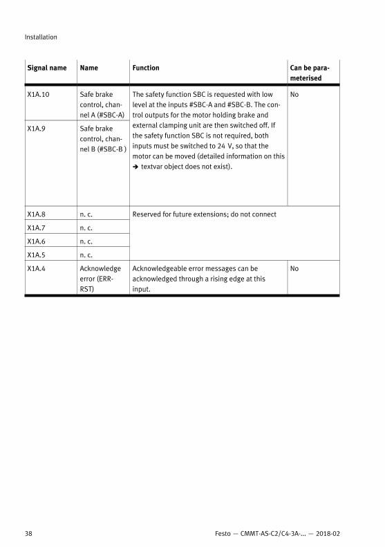
Signal name Name Function Can be para-meterised
X1A.10 Safe brakecontrol, chan-nel A (#SBC-A)
X1A.9 Safe brakecontrol, chan-nel B (#SBC-B )
The safety function SBC is requested with lowlevel at the inputs #SBC-A and #SBC-B. The con-trol outputs for the motor holding brake andexternal clamping unit are then switched off. Ifthe safety function SBC is not required, bothinputs must be switched to 24 V, so that themotor can be moved (detailed information on thisè textvar object does not exist).
No
X1A.8 n. c.
X1A.7 n. c.
X1A.6 n. c.
X1A.5 n. c.
Reserved for future extensions; do not connect
X1A.4 Acknowledgeerror (ERR-RST)
Acknowledgeable error messages can beacknowledged through a rising edge at thisinput.
No
Installation
38 Festo — CMMT-AS-C2/C4-3A-... — 2018-02
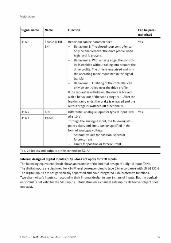
Signal name Name Function Can be para-meterised
X1A.3 Enable (CTRL-EN)
Behaviour can be parameterised.– Behaviour 1: The closed-loop controller can
only be enabled over the drive profile whenhigh level is present.
– Behaviour 2: With a rising edge, the control-ler is enabled without taking into account thedrive profile. The drive is energised and is inthe operating mode requested in the signaltransfer.
– Behaviour 3: Enabling of the controller canonly be controlled over the drive profile.
If the request is withdrawn, the drive is brakedwith a behaviour of the stop category 1. After thebraking ramp ends, the brake is engaged and theoutput stage is switched off functionally.
Yes
X1A.2 AIN0
X1A.1 #AIN0
Differential analogue input for typical input levelof ± 10 V Through the analogue input, the following set-point values and limits can be specified in theform of analogue voltage:– Setpoint values for position, speed or
force/current– Limits for position or force/current
Yes
Tab. 23 Inputs and outputs at the connection [X1A]
Internal design of digital inputs (DIN) - does not apply for STO inputsThe following equivalent circuit shows an example of the internal design of a digital input (DIN).The digital inputs are designed for +24 V level corresponding to type 3 in accordance with EN 61131-2.The digital inputs are not galvanically separated and have integrated EMC protective functions.Two-channel safe inputs correspond in their internal design to two 1-channel inputs. But the equival-ent circuit is not valid for the STO inputs. Information on 2-channel safe inputs è textvar object doesnot exist.
Installation
39Festo — CMMT-AS-C2/C4-3A-... — 2018-02
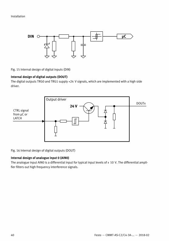
µCDIN
Fig. 15 Internal design of digital inputs (DIN)
Internal design of digital outputs (DOUT)The digital outputs TRG0 and TRG1 supply +24 V signals, which are implemented with a high sidedriver.
Fig. 16 Internal design of digital outputs (DOUT)
Internal design of analogue input 0 (AIN0)The analogue input AIN0 is a differential input for typical input levels of ± 10 V. The differential ampli-fier filters out high frequency interference signals.
Installation
40 Festo — CMMT-AS-C2/C4-3A-... — 2018-02
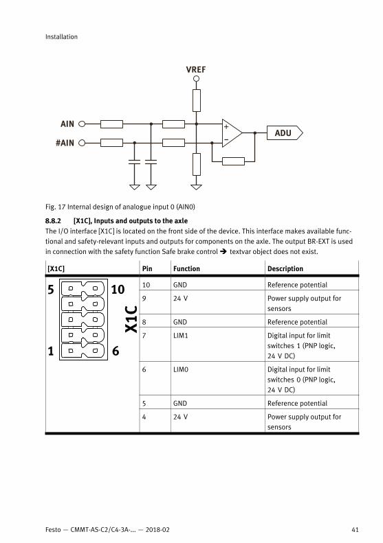
AIN
VREF
ADU
#AIN
Fig. 17 Internal design of analogue input 0 (AIN0)
8.8.2 [X1C], Inputs and outputs to the axleThe I/O interface [X1C] is located on the front side of the device. This interface makes available func-tional and safety-relevant inputs and outputs for components on the axle. The output BR-EXT is usedin connection with the safety function Safe brake control è textvar object does not exist.
[X1C] Pin Function Description
10 GND Reference potential
9 24 V Power supply output forsensors
8 GND Reference potential
7 LIM1 Digital input for limitswitches 1 (PNP logic,24 V DC)
6 LIM0 Digital input for limitswitches 0 (PNP logic,24 V DC)
5 GND Reference potential
4 24 V Power supply output forsensors
Installation
41Festo — CMMT-AS-C2/C4-3A-... — 2018-02
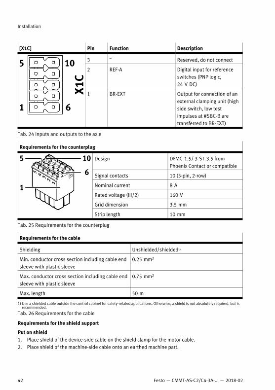
[X1C] Pin Function Description
3 – Reserved, do not connect
2 REF-A Digital input for referenceswitches (PNP logic,24 V DC)
1 BR-EXT Output for connection of anexternal clamping unit (highside switch, low testimpulses at #SBC-B aretransferred to BR-EXT)
Tab. 24 Inputs and outputs to the axle
Requirements for the counterplug
Design DFMC 1.5/ 3-ST-3.5 fromPhoenix Contact or compatible
Signal contacts 10 (5-pin, 2-row)
Nominal current 8 A
Rated voltage (III/2) 160 V
Grid dimension 3.5 mm
Strip length 10 mm
Tab. 25 Requirements for the counterplug
Requirements for the cable
Shielding Unshielded/shielded1)
Min. conductor cross section including cable endsleeve with plastic sleeve
0.25 mm2
Max. conductor cross section including cable endsleeve with plastic sleeve
0.75 mm2
Max. length 50 m
1) Use a shielded cable outside the control cabinet for safety-related applications. Otherwise, a shield is not absolutely required, but isrecommended.
Tab. 26 Requirements for the cable
Requirements for the shield support
Put on shield1. Place shield of the device-side cable on the shield clamp for the motor cable.2. Place shield of the machine-side cable onto an earthed machine part.
Installation
42 Festo — CMMT-AS-C2/C4-3A-... — 2018-02
8.8.3 [X2], Sensor interface 1The sensor interface [X2] is located on the front side of the device. The sensor interface [X2] primarilyserves to connect the position sensor integrated into the motor.
Supported standards/protocols Supported sensors
Hiperface SEK/SEL 37SKS/SKM 36
EnDat 2.2 ECI 1118/EBI 1135ECI 1119/EQI 1131ECN 1113/EQN 1125ECN 1123/EQN 1135
EnDat 2.1 Only in connection with motors of the seriesEMMS-AS from Festo that have an integratedsensor with EnDat 2.1 protocol
Digital incremental sensor with square wave sig-nals and with RS422-compatible signal output(differential A, B, N signals)
ROD 426 or compatible
Analogue SIN/COS incremental sensor with dif-ferential analogue signals with 1 Vss
HEIDENHAIN LS 187/LS 487 (20 µm signal peri-od) or compatible
Position sensor with asynchronous two-wirecommunication interface (RS485)
Nikon MAR-M50A or compatible (18 bit dataframes)
Tab. 27 Supported standards and protocols of the sensor interface [X2]
NOTICE!
Damage to the sensor when sensor type is changed.The servo drive can provide 5 V or 10 V sensor supply. Through configuration of the sensor, the sup-ply voltage is established for the sensor. The sensor can be damaged if the configuration is not adjus-ted before connection of another sensor type.• When changing the sensor type: Comply with specified steps.
Change of the sensor type1. Disconnect sensor from the device.2. Set up and configure new sensor type in the CMMT-AS.3. Save setting in the CMMT-AS.4. Switch off CMMT-AS.5. Connect new sensor type.6. Switch CMMT-AS back on.At the connection [X2], voltage drops in the sensor cable are compensated for sensors with purelydigital communication, which require a regulated +5 V supply (EnDat 2.1, Nikon).The connection [X2] is designed as an RJ45 socket. An LED is integrated into the RJ45 socket. For digit-al incremental sensors, the LED lights green when the sensor interface is active. For sensors with com-munication interface, the LED lights green when a connection to the sensor exists.
Installation
43Festo — CMMT-AS-C2/C4-3A-... — 2018-02
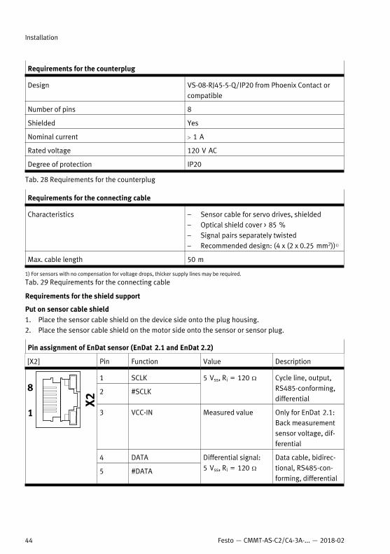
Requirements for the counterplug
Design VS-08-RJ45-5-Q/IP20 from Phoenix Contact orcompatible
Number of pins 8
Shielded Yes
Nominal current > 1 A
Rated voltage 120 V AC
Degree of protection IP20
Tab. 28 Requirements for the counterplug
Requirements for the connecting cable
Characteristics – Sensor cable for servo drives, shielded– Optical shield cover > 85 %– Signal pairs separately twisted– Recommended design: (4 x (2 x 0.25 mm2))1)
Max. cable length 50 m
1) For sensors with no compensation for voltage drops, thicker supply lines may be required.
Tab. 29 Requirements for the connecting cable
Requirements for the shield support
Put on sensor cable shield1. Place the sensor cable shield on the device side onto the plug housing.2. Place the sensor cable shield on the motor side onto the sensor or sensor plug.
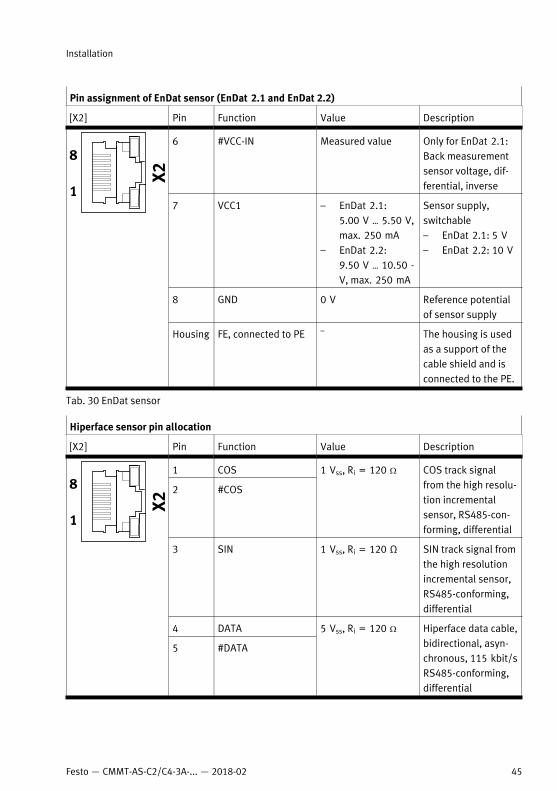
Pin assignment of EnDat sensor (EnDat 2.1 and EnDat 2.2)
[X2] Pin Function Value Description
1 SCLK
2 #SCLK
5 Vss, Ri = 120 W Cycle line, output,RS485-conforming,differential
3 VCC-IN Measured value Only for EnDat 2.1:Back measurementsensor voltage, dif-ferential
4 DATA
5 #DATA
Differential signal:5 Vss, Ri = 120 W
Data cable, bidirec-tional, RS485-con-forming, differential
Installation
44 Festo — CMMT-AS-C2/C4-3A-... — 2018-02
Pin assignment of EnDat sensor (EnDat 2.1 and EnDat 2.2)
[X2] Pin Function Value Description
6 #VCC-IN Measured value Only for EnDat 2.1:Back measurementsensor voltage, dif-ferential, inverse
7 VCC1 – EnDat 2.1:5.00 V … 5.50 V,max. 250 mA
– EnDat 2.2:9.50 V … 10.50 -V, max. 250 mA
Sensor supply,switchable– EnDat 2.1: 5 V– EnDat 2.2: 10 V
8 GND 0 V Reference potentialof sensor supply
Housing FE, connected to PE – The housing is usedas a support of thecable shield and isconnected to the PE.
Tab. 30 EnDat sensor
Hiperface sensor pin allocation
[X2] Pin Function Value Description
1 COS
2 #COS
1 Vss, Ri = 120 W COS track signalfrom the high resolu-tion incrementalsensor, RS485-con-forming, differential
3 SIN 1 Vss, Ri = 120 Ω SIN track signal fromthe high resolutionincremental sensor,RS485-conforming,differential
4 DATA
5 #DATA
5 Vss, Ri = 120 W Hiperface data cable,bidirectional, asyn-chronous, 115 kbit/sRS485-conforming,differential
Installation
45Festo — CMMT-AS-C2/C4-3A-... — 2018-02
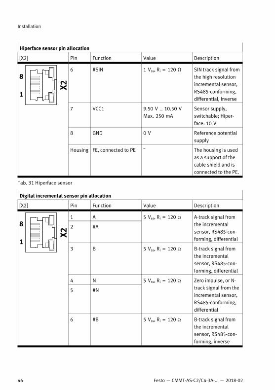
Hiperface sensor pin allocation
[X2] Pin Function Value Description
6 #SIN 1 Vss, Ri = 120 Ω SIN track signal fromthe high resolutionincremental sensor,RS485-conforming,differential, inverse
7 VCC1 9.50 V … 10.50 VMax. 250 mA
Sensor supply,switchable; Hiper-face: 10 V
8 GND 0 V Reference potentialsupply
Housing FE, connected to PE – The housing is usedas a support of thecable shield and isconnected to the PE.
Tab. 31 Hiperface sensor
Digital incremental sensor pin allocation
[X2] Pin Function Value Description
1 A
2 #A
5 Vss, Ri = 120 W A-track signal fromthe incrementalsensor, RS485-con-forming, differential
3 B 5 Vss, Ri = 120 W B-track signal fromthe incrementalsensor, RS485-con-forming, differential
4 N
5 #N
5 Vss, Ri = 120 W Zero impulse, or N-track signal from theincremental sensor,RS485-conforming,differential
6 #B 5 Vss, Ri = 120 W B-track signal fromthe incrementalsensor, RS485-con-forming, inverse
Installation
46 Festo — CMMT-AS-C2/C4-3A-... — 2018-02
Digital incremental sensor pin allocation
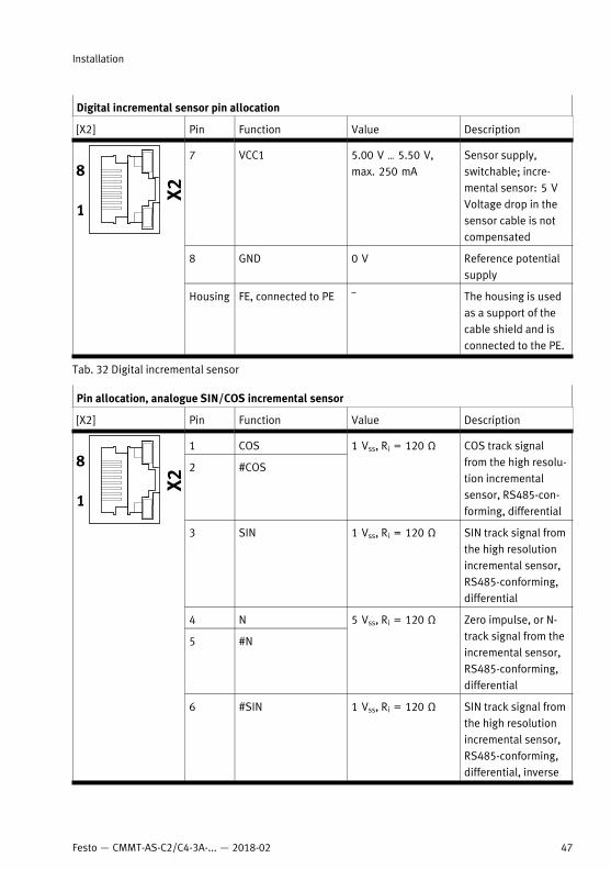
[X2] Pin Function Value Description
7 VCC1 5.00 V … 5.50 V,max. 250 mA
Sensor supply,switchable; incre-mental sensor: 5 VVoltage drop in thesensor cable is notcompensated
8 GND 0 V Reference potentialsupply
Housing FE, connected to PE – The housing is usedas a support of thecable shield and isconnected to the PE.
Tab. 32 Digital incremental sensor
Pin allocation, analogue SIN/COS incremental sensor
[X2] Pin Function Value Description
1 COS
2 #COS
1 Vss, Ri = 120 Ω COS track signalfrom the high resolu-tion incrementalsensor, RS485-con-forming, differential
3 SIN 1 Vss, Ri = 120 Ω SIN track signal fromthe high resolutionincremental sensor,RS485-conforming,differential
4 N
5 #N
5 Vss, Ri = 120 Ω Zero impulse, or N-track signal from theincremental sensor,RS485-conforming,differential
6 #SIN 1 Vss, Ri = 120 Ω SIN track signal fromthe high resolutionincremental sensor,RS485-conforming,differential, inverse
Installation
47Festo — CMMT-AS-C2/C4-3A-... — 2018-02
Pin allocation, analogue SIN/COS incremental sensor
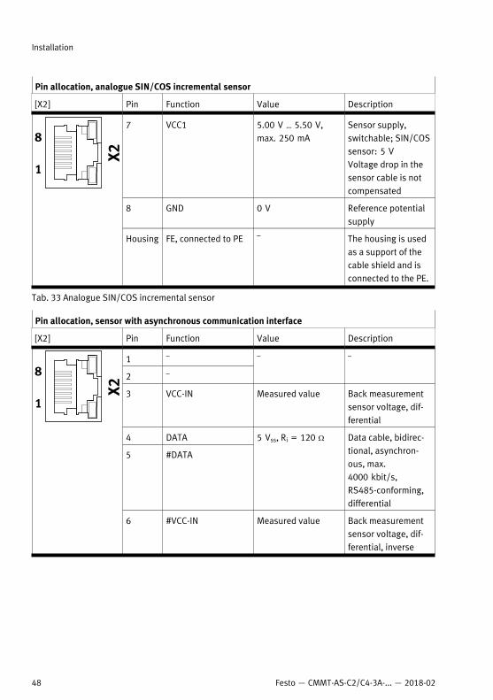
[X2] Pin Function Value Description
7 VCC1 5.00 V … 5.50 V,max. 250 mA
Sensor supply,switchable; SIN/COSsensor: 5 VVoltage drop in thesensor cable is notcompensated
8 GND 0 V Reference potentialsupply
Housing FE, connected to PE – The housing is usedas a support of thecable shield and isconnected to the PE.
Tab. 33 Analogue SIN/COS incremental sensor
Pin allocation, sensor with asynchronous communication interface
[X2] Pin Function Value Description
1 –
2 –
– –
3 VCC-IN Measured value Back measurementsensor voltage, dif-ferential
4 DATA
5 #DATA
5 Vss, Ri = 120 W Data cable, bidirec-tional, asynchron-ous, max.4000 kbit/s,RS485-conforming,differential
6 #VCC-IN Measured value Back measurementsensor voltage, dif-ferential, inverse
Installation
48 Festo — CMMT-AS-C2/C4-3A-... — 2018-02
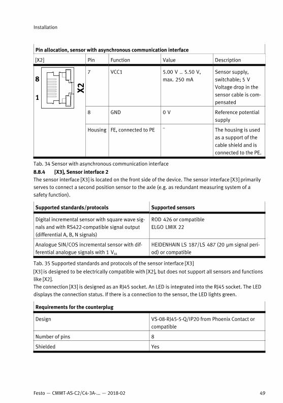
Pin allocation, sensor with asynchronous communication interface
[X2] Pin Function Value Description
7 VCC1 5.00 V … 5.50 V,max. 250 mA
Sensor supply,switchable; 5 VVoltage drop in thesensor cable is com-pensated
8 GND 0 V Reference potentialsupply
Housing FE, connected to PE – The housing is usedas a support of thecable shield and isconnected to the PE.
Tab. 34 Sensor with asynchronous communication interface
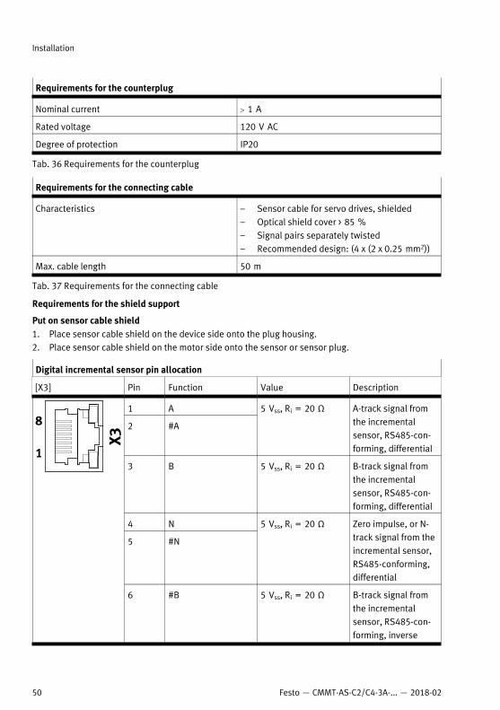
8.8.4 [X3], Sensor interface 2The sensor interface [X3] is located on the front side of the device. The sensor interface [X3] primarilyserves to connect a second position sensor to the axle (e.g. as redundant measuring system of asafety function).
Supported standards/protocols Supported sensors
Digital incremental sensor with square wave sig-nals and with RS422-compatible signal output(differential A, B, N signals)
ROD 426 or compatibleELGO LMIX 22
Analogue SIN/COS incremental sensor with dif-ferential analogue signals with 1 Vss
HEIDENHAIN LS 187/LS 487 (20 µm signal peri-od) or compatible
Tab. 35 Supported standards and protocols of the sensor interface [X3]
[X3] is designed to be electrically compatible with [X2], but does not support all sensors and functionslike [X2].The connection [X3] is designed as an RJ45 socket. An LED is integrated into the RJ45 socket. The LEDdisplays the connection status. If there is a connection to the sensor, the LED lights green.
Requirements for the counterplug
Design VS-08-RJ45-5-Q/IP20 from Phoenix Contact orcompatible
Number of pins 8
Shielded Yes
Installation
49Festo — CMMT-AS-C2/C4-3A-... — 2018-02
Requirements for the counterplug
Nominal current > 1 A
Rated voltage 120 V AC
Degree of protection IP20
Tab. 36 Requirements for the counterplug
Requirements for the connecting cable
Characteristics – Sensor cable for servo drives, shielded– Optical shield cover > 85 %– Signal pairs separately twisted– Recommended design: (4 x (2 x 0.25 mm2))
Max. cable length 50 m
Tab. 37 Requirements for the connecting cable
Requirements for the shield support
Put on sensor cable shield1. Place sensor cable shield on the device side onto the plug housing.2. Place sensor cable shield on the motor side onto the sensor or sensor plug.
Digital incremental sensor pin allocation
[X3] Pin Function Value Description
1 A
2 #A
5 Vss, Ri = 20 Ω A-track signal fromthe incrementalsensor, RS485-con-forming, differential
3 B 5 Vss, Ri = 20 Ω B-track signal fromthe incrementalsensor, RS485-con-forming, differential
4 N
5 #N
5 Vss, Ri = 20 Ω Zero impulse, or N-track signal from theincremental sensor,RS485-conforming,differential
6 #B 5 Vss, Ri = 20 Ω B-track signal fromthe incrementalsensor, RS485-con-forming, inverse
Installation
50 Festo — CMMT-AS-C2/C4-3A-... — 2018-02
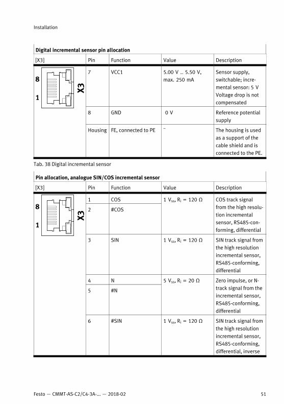
Digital incremental sensor pin allocation
[X3] Pin Function Value Description
7 VCC1 5.00 V … 5.50 V,max. 250 mA
Sensor supply,switchable; incre-mental sensor: 5 VVoltage drop is notcompensated
8 GND 0 V Reference potentialsupply
Housing FE, connected to PE – The housing is usedas a support of thecable shield and isconnected to the PE.
Tab. 38 Digital incremental sensor
Pin allocation, analogue SIN/COS incremental sensor
[X3] Pin Function Value Description
1 COS
2 #COS
1 Vss, Ri = 120 Ω COS track signalfrom the high resolu-tion incrementalsensor, RS485-con-forming, differential
3 SIN 1 Vss, Ri = 120 Ω SIN track signal fromthe high resolutionincremental sensor,RS485-conforming,differential
4 N
5 #N
5 Vss, Ri = 20 Ω Zero impulse, or N-track signal from theincremental sensor,RS485-conforming,differential
6 #SIN 1 Vss, Ri = 120 Ω SIN track signal fromthe high resolutionincremental sensor,RS485-conforming,differential, inverse
Installation
51Festo — CMMT-AS-C2/C4-3A-... — 2018-02
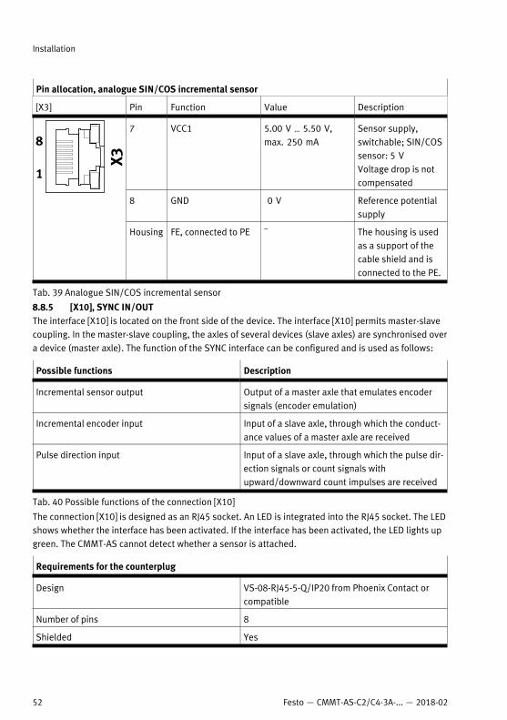
Pin allocation, analogue SIN/COS incremental sensor
[X3] Pin Function Value Description
7 VCC1 5.00 V … 5.50 V,max. 250 mA
Sensor supply,switchable; SIN/COSsensor: 5 VVoltage drop is notcompensated
8 GND 0 V Reference potentialsupply
Housing FE, connected to PE – The housing is usedas a support of thecable shield and isconnected to the PE.
Tab. 39 Analogue SIN/COS incremental sensor
8.8.5 [X10], SYNC IN/OUTThe interface [X10] is located on the front side of the device. The interface [X10] permits master-slavecoupling. In the master-slave coupling, the axles of several devices (slave axles) are synchronised overa device (master axle). The function of the SYNC interface can be configured and is used as follows:
Possible functions Description
Incremental sensor output Output of a master axle that emulates encodersignals (encoder emulation)
Incremental encoder input Input of a slave axle, through which the conduct-ance values of a master axle are received
Pulse direction input Input of a slave axle, through which the pulse dir-ection signals or count signals withupward/downward count impulses are received
Tab. 40 Possible functions of the connection [X10]
The connection [X10] is designed as an RJ45 socket. An LED is integrated into the RJ45 socket. The LEDshows whether the interface has been activated. If the interface has been activated, the LED lights upgreen. The CMMT-AS cannot detect whether a sensor is attached.
Requirements for the counterplug
Design VS-08-RJ45-5-Q/IP20 from Phoenix Contact orcompatible
Number of pins 8
Shielded Yes
Installation
52 Festo — CMMT-AS-C2/C4-3A-... — 2018-02
Requirements for the counterplug
Nominal current > 1 A
Rated voltage 120 V AC
Degree of protection IP20
Tab. 41 Requirements for the counterplug
Requirements for the connecting cable
Characteristics – Sensor cable for servo drives, shielded– Optical shield cover > 85 %– Signal pairs separately twisted– Recommended design: (4 x (2 x 0.25 mm2))
Max. cable length 3 m
Tab. 42 Requirements for the connecting cable
Requirements for the shield supportPlace both sides of the connecting cable shield onto the plug housings.
Possible connections
Connection possibilities Description
Direct connection of 2 devices Two devices can be connected directly with apatch cable (point-to-point connection). Recommendation: Use patch cable of categoryCat 5E; maximum length: 25 cm
Connection of several devices over RJ45 Tadapter and patch cables
A maximum of 16 devices may be connected.Recommendation: Use T adapter and patchcables of category Cat 5E; maximum length percable: 25 cm
Connection of several devices over patch cablesand a connector box (accessoriesè www.festo.com/catalogue)
A maximum of 16 devices may be connected.Recommendation: Use patch cables of categoryCat 5E, maximum length per cable: 100 cm
Tab. 43 Connection possibilities
Installation
53Festo — CMMT-AS-C2/C4-3A-... — 2018-02
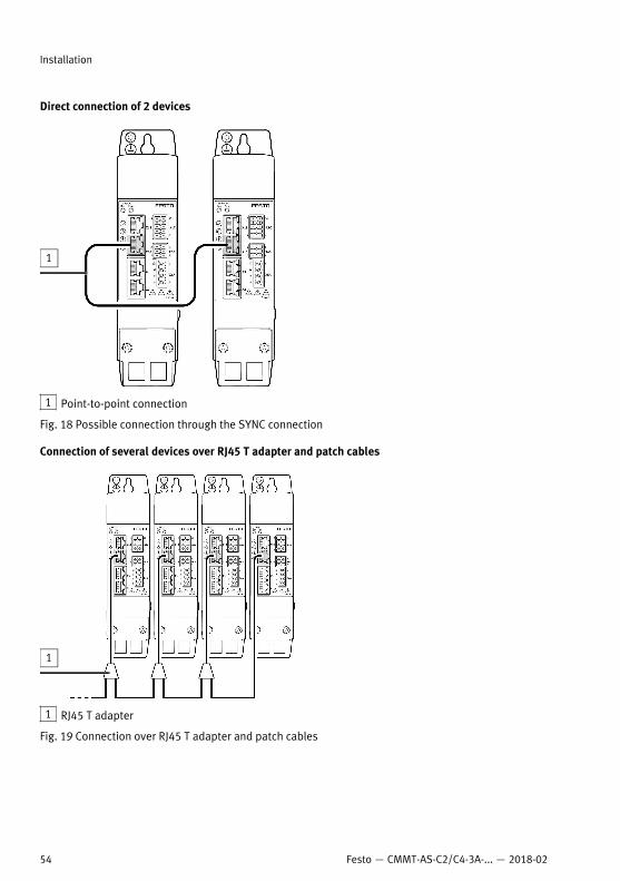
Direct connection of 2 devices
1 Point-to-point connection
Fig. 18 Possible connection through the SYNC connection
Connection of several devices over RJ45 T adapter and patch cables
1 RJ45 T adapter
Fig. 19 Connection over RJ45 T adapter and patch cables
Installation
54 Festo — CMMT-AS-C2/C4-3A-... — 2018-02
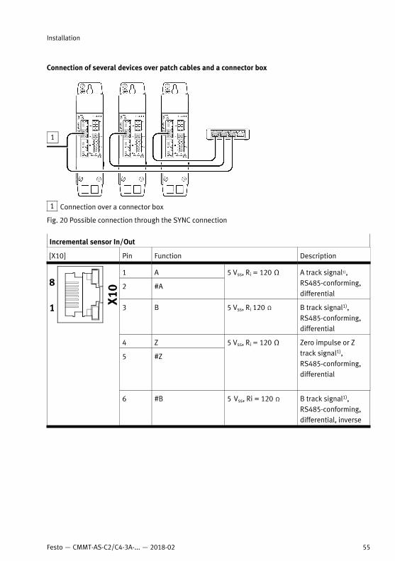
Connection of several devices over patch cables and a connector box
1 Connection over a connector box
Fig. 20 Possible connection through the SYNC connection
Incremental sensor In/Out
[X10] Pin Function Description
1 A
2 #A
5 Vss, Ri = 120 Ω A track signal1),RS485-conforming,differential
3 B 5 Vss, Ri 120 Ω B track signal1),RS485-conforming,differential
4 Z
5 #Z
5 Vss, Ri = 120 Ω Zero impulse or Ztrack signal1),RS485-conforming,differential
6 #B 5 Vss, Ri = 120 Ω B track signal1),RS485-conforming,differential, inverse
Installation
55Festo — CMMT-AS-C2/C4-3A-... — 2018-02
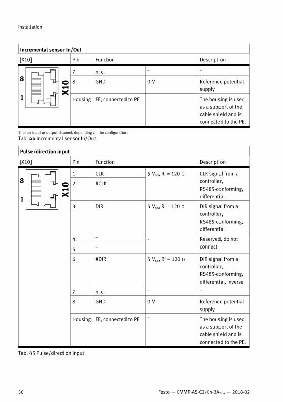
Incremental sensor In/Out
[X10] Pin Function Description
7 n. c. – –
8 GND 0 V Reference potentialsupply
Housing FE, connected to PE – The housing is usedas a support of thecable shield and isconnected to the PE.
1) of an input or output channel, depending on the configuration
Tab. 44 Incremental sensor In/Out
Pulse/direction input
[X10] Pin Function Description
1 CLK
2 #CLK
5 Vss, Ri = 120 Ω CLK signal from acontroller,RS485-conforming,differential
3 DIR 5 Vss, Ri = 120 Ω DIR signal from acontroller,RS485-conforming,differential
4 –
5 –
- Reserved, do notconnect
6 #DIR 5 Vss, Ri = 120 Ω DIR signal from acontroller,RS485-conforming,differential, inverse
7 n. c. – –
8 GND 0 V Reference potentialsupply
Housing FE, connected to PE – The housing is usedas a support of thecable shield and isconnected to the PE.
Tab. 45 Pulse/direction input
Installation
56 Festo — CMMT-AS-C2/C4-3A-... — 2018-02
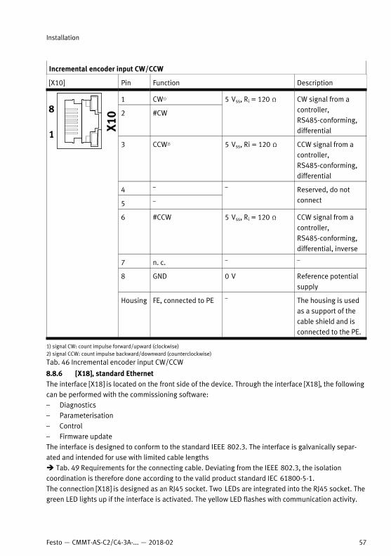
Incremental encoder input CW/CCW
[X10] Pin Function Description
1 CW1)
2 #CW
5 Vss, Ri = 120 Ω CW signal from acontroller,RS485-conforming,differential
3 CCW2) 5 Vss, Ri = 120 Ω CCW signal from acontroller,RS485-conforming,differential
4 –
5 –
– Reserved, do notconnect
6 #CCW 5 Vss, Ri = 120 Ω CCW signal from acontroller,RS485-conforming,differential, inverse
7 n. c. – –
8 GND 0 V Reference potentialsupply
Housing FE, connected to PE – The housing is usedas a support of thecable shield and isconnected to the PE.
1) signal CW: count impulse forward/upward (clockwise)2) signal CCW: count impulse backward/downward (counterclockwise)
Tab. 46 Incremental encoder input CW/CCW
8.8.6 [X18], standard EthernetThe interface [X18] is located on the front side of the device. Through the interface [X18], the followingcan be performed with the commissioning software:– Diagnostics– Parameterisation– Control– Firmware updateThe interface is designed to conform to the standard IEEE 802.3. The interface is galvanically separ-ated and intended for use with limited cable lengthsè Tab. 49 Requirements for the connecting cable. Deviating from the IEEE 802.3, the isolationcoordination is therefore done according to the valid product standard IEC 61800-5-1.The connection [X18] is designed as an RJ45 socket. Two LEDs are integrated into the RJ45 socket. Thegreen LED lights up if the interface is activated. The yellow LED flashes with communication activity.
Installation
57Festo — CMMT-AS-C2/C4-3A-... — 2018-02
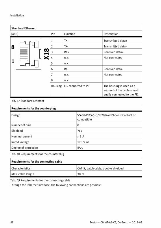
Standard Ethernet
[X18] Pin Function Description
1 TX+ Transmitted data+
2 TX- Transmitted data-
3 RX+ Received data+
4 n. c.
5 n. c.
Not connected
6 RX- Received data-
7 n. c.
8 n. c.
Not connected
Housing FE, connected to PE The housing is used as asupport of the cable shieldand is connected to the PE.
Tab. 47 Standard Ethernet
Requirements for the counterplug
Design VS-08-RJ45-5-Q/IP20 fromPhoenix Contact orcompatible
Number of pins 8
Shielded Yes
Nominal current > 1 A
Rated voltage 120 V AC
Degree of protection IP20
Tab. 48 Requirements for the counterplug
Requirements for the connecting cable
Characteristics CAT 5, patch cable, double shielded
Max. cable length 30 m
Tab. 49 Requirements for the connecting cable
Through the Ethernet interface, the following connections are possible:
Installation
58 Festo — CMMT-AS-C2/C4-3A-... — 2018-02
Connections Description
Point-to-point connection The device is connected directly to the PC via anEthernet cable.
Network connection The device is connected to an Ethernet network.
Tab. 50 Options for connection
The device supports the following methods of IP configuration (based on IPv4):
Methods Description
Obtain IP address automatically (DHCP client) The device obtains its IP configuration from aDHCP server in your network. This method is suit-able for networks in which a DHCP server alreadyexists.
Fixed IP configuration The device uses a fixed IP configuration.The IP configuration of the device can be perman-ently assigned manually. However, the devicecan only be addressed if the assigned IP config-uration matches the IP configuration of the PC.Factory setting: 192.168.0.1
Tab. 51 Options for IP configuration
1. Connect CMMT to your network or directly to the PC via a hub/switch.2. Place both sides of the cable shield onto the plug housings.8.8.7 [X19], Real-time Ethernet (RTE) port 1 and port 2The interface [X19] is located on the top of the device. The interface [X19] permits RTE communication.The following protocols are supported by the interface [X19], depending on the product design:
Product variant Supported protocol
CMMT-AS-...-EC EtherCAT
CMMT-AS-...-EP EtherNet/IP
CMMT-AS-...-PN PROFINET
Tab. 52 Supported protocol
The physical level of the interface also fulfils the requirements according to IEEE 802.3. The interfaceis galvanically separated and intended for use with limited cable lengthsè Tab. 55 Requirements for the connecting cable.The interface [X19] makes 2 ports available.– Port 1, labelled on the device with [X19, XF1 IN]– Port 2, labelled on the device with [X19, XF2 OUT]Two LEDs are integrated into each of the two RJ45 sockets. The behaviour of the LEDs depends on thebus protocol. Both LEDs are not always used.
Installation
59Festo — CMMT-AS-C2/C4-3A-... — 2018-02
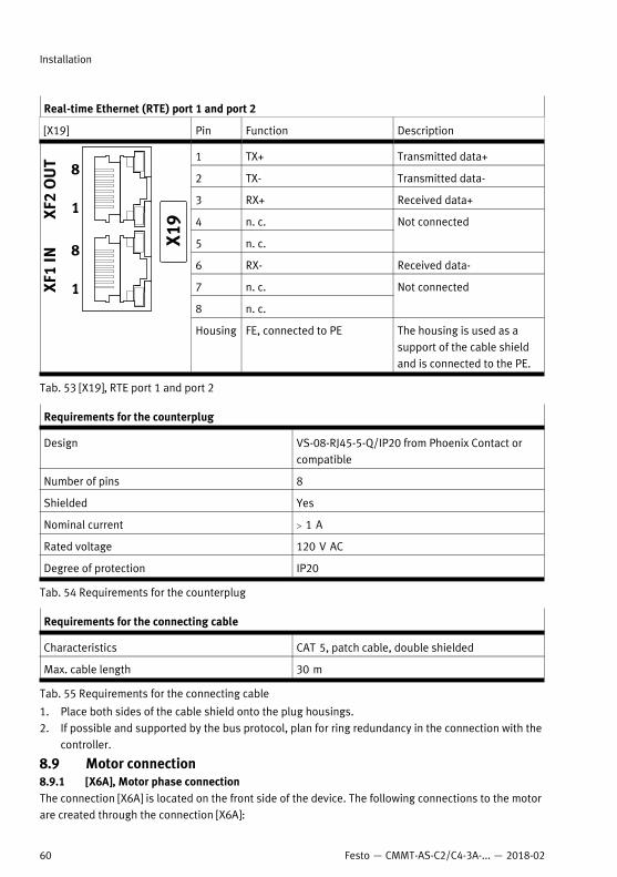
Real-time Ethernet (RTE) port 1 and port 2
[X19] Pin Function Description
1 TX+ Transmitted data+
2 TX- Transmitted data-
3 RX+ Received data+
4 n. c.
5 n. c.
Not connected
6 RX- Received data-
7 n. c.
8 n. c.
Not connected
Housing FE, connected to PE The housing is used as asupport of the cable shieldand is connected to the PE.
Tab. 53 [X19], RTE port 1 and port 2
Requirements for the counterplug
Design VS-08-RJ45-5-Q/IP20 from Phoenix Contact orcompatible
Number of pins 8
Shielded Yes
Nominal current > 1 A
Rated voltage 120 V AC
Degree of protection IP20
Tab. 54 Requirements for the counterplug
Requirements for the connecting cable
Characteristics CAT 5, patch cable, double shielded
Max. cable length 30 m
Tab. 55 Requirements for the connecting cable
1. Place both sides of the cable shield onto the plug housings.2. If possible and supported by the bus protocol, plan for ring redundancy in the connection with the
controller.
8.9 Motor connection8.9.1 [X6A], Motor phase connectionThe connection [X6A] is located on the front side of the device. The following connections to the motorare created through the connection [X6A]:
Installation
60 Festo — CMMT-AS-C2/C4-3A-... — 2018-02
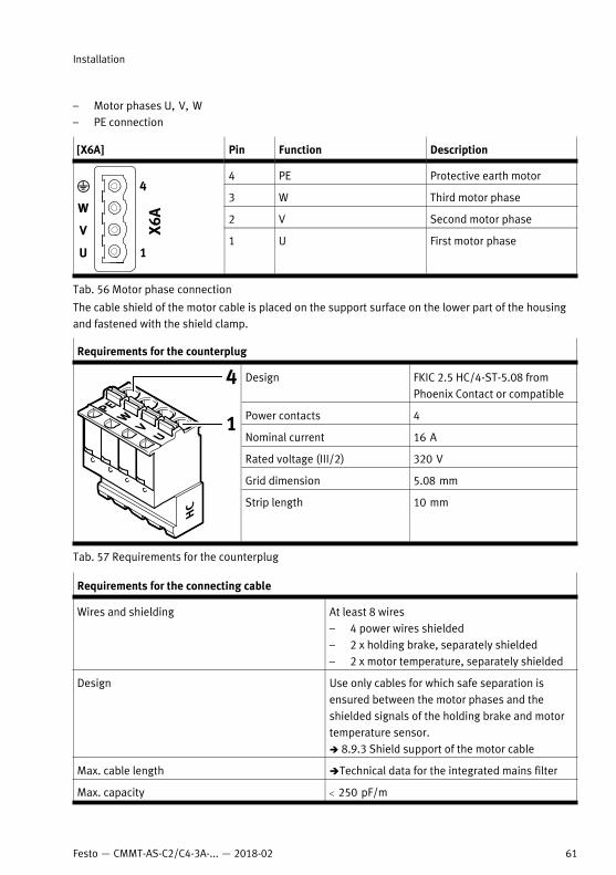
– Motor phases U, V, W– PE connection
[X6A] Pin Function Description
4 PE Protective earth motor
3 W Third motor phase
2 V Second motor phase
1 U First motor phase
Tab. 56 Motor phase connection
The cable shield of the motor cable is placed on the support surface on the lower part of the housingand fastened with the shield clamp.
Requirements for the counterplug
Design FKIC 2.5 HC/4-ST-5.08 fromPhoenix Contact or compatible
Power contacts 4
Nominal current 16 A
Rated voltage (III/2) 320 V
Grid dimension 5.08 mm
Strip length 10 mm
Tab. 57 Requirements for the counterplug
Requirements for the connecting cable
Wires and shielding At least 8 wires– 4 power wires shielded– 2 x holding brake, separately shielded– 2 x motor temperature, separately shielded
Design Use only cables for which safe separation isensured between the motor phases and theshielded signals of the holding brake and motortemperature sensor.è 8.9.3 Shield support of the motor cable
Max. cable length èTechnical data for the integrated mains filter
Max. capacity < 250 pF/m
Installation
61Festo — CMMT-AS-C2/C4-3A-... — 2018-02
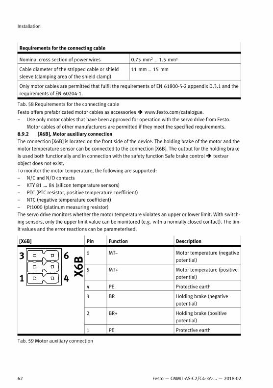
Requirements for the connecting cable
Nominal cross section of power wires 0.75 mm2 … 1.5 mm²
Cable diameter of the stripped cable or shieldsleeve (clamping area of the shield clamp)
11 mm … 15 mm
Only motor cables are permitted that fulfil the requirements of EN 61800-5-2 appendix D.3.1 and therequirements of EN 60204-1.
Tab. 58 Requirements for the connecting cable
Festo offers prefabricated motor cables as accessories è www.festo.com/catalogue.– Use only motor cables that have been approved for operation with the servo drive from Festo.
Motor cables of other manufacturers are permitted if they meet the specified requirements.8.9.2 [X6B], Motor auxiliary connectionThe connection [X6B] is located on the front side of the device. The holding brake of the motor and themotor temperature sensor can be connected to the connection [X6B]. The output for the holding brakeis used both functionally and in connection with the safety function Safe brake control è textvarobject does not exist. To monitor the motor temperature, the following are supported:– N/C and N/O contacts– KTY 81 … 84 (silicon temperature sensors)– PTC (PTC resistor, positive temperature coefficient)– NTC (negative temperature coefficient)– Pt1000 (platinum measuring resistor)The servo drive monitors whether the motor temperature violates an upper or lower limit. With switch-ing sensors, only the upper limit value can be monitored (e.g. with a normally closed contact). The lim-it values and the error reactions can be parameterised.
[X6B] Pin Function Description
6 MT– Motor temperature (negativepotential)
5 MT+ Motor temperature (positivepotential)
4 PE Protective earth
3 BR– Holding brake (negativepotential)
2 BR+ Holding brake (positivepotential)
1 PE Protective earth
Tab. 59 Motor auxiliary connection
Installation
62 Festo — CMMT-AS-C2/C4-3A-... — 2018-02
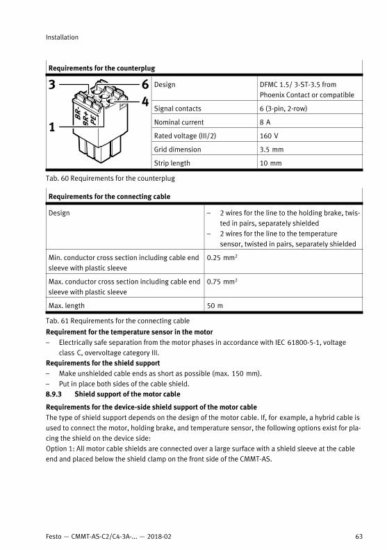
Requirements for the counterplug
Design DFMC 1.5/ 3-ST-3.5 fromPhoenix Contact or compatible
Signal contacts 6 (3-pin, 2-row)
Nominal current 8 A
Rated voltage (III/2) 160 V
Grid dimension 3.5 mm
Strip length 10 mm
Tab. 60 Requirements for the counterplug
Requirements for the connecting cable
Design – 2 wires for the line to the holding brake, twis-ted in pairs, separately shielded
– 2 wires for the line to the temperaturesensor, twisted in pairs, separately shielded
Min. conductor cross section including cable endsleeve with plastic sleeve
0.25 mm2
Max. conductor cross section including cable endsleeve with plastic sleeve
0.75 mm2
Max. length 50 m
Tab. 61 Requirements for the connecting cable
Requirement for the temperature sensor in the motor– Electrically safe separation from the motor phases in accordance with IEC 61800-5-1, voltage
class C, overvoltage category III.Requirements for the shield support– Make unshielded cable ends as short as possible (max. 150 mm).– Put in place both sides of the cable shield.8.9.3 Shield support of the motor cable
Requirements for the device-side shield support of the motor cableThe type of shield support depends on the design of the motor cable. If, for example, a hybrid cable isused to connect the motor, holding brake, and temperature sensor, the following options exist for pla-cing the shield on the device side:Option 1: All motor cable shields are connected over a large surface with a shield sleeve at the cableend and placed below the shield clamp on the front side of the CMMT-AS.
Installation
63Festo — CMMT-AS-C2/C4-3A-... — 2018-02
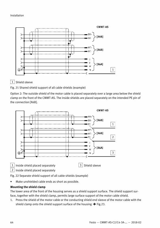
1 Shield sleeve
Fig. 21 Shared shield support of all cable shields (example)
Option 2: The outside shield of the motor cable is placed separately over a large area below the shieldclamp on the front of the CMMT-AS. The inside shields are placed separately on the intended PE pin ofthe connection [X6B].
1 Inside shield placed separately
2 Inside shield placed separately
3 Shield sleeve
Fig. 22 Separate shield support of all cable shields (example)
• Make unshielded cable ends as short as possible.
Mounting the shield clampThe lower area of the front of the housing serves as a shield support surface. The shield support sur-face, together with the shield clamp, permits large surface support of the motor cable shield.1. Press the shield of the motor cable or the conducting shield end sleeve of the motor cable with the
shield clamp onto the shield support surface of the housing è Fig.23.
Installation
64 Festo — CMMT-AS-C2/C4-3A-... — 2018-02
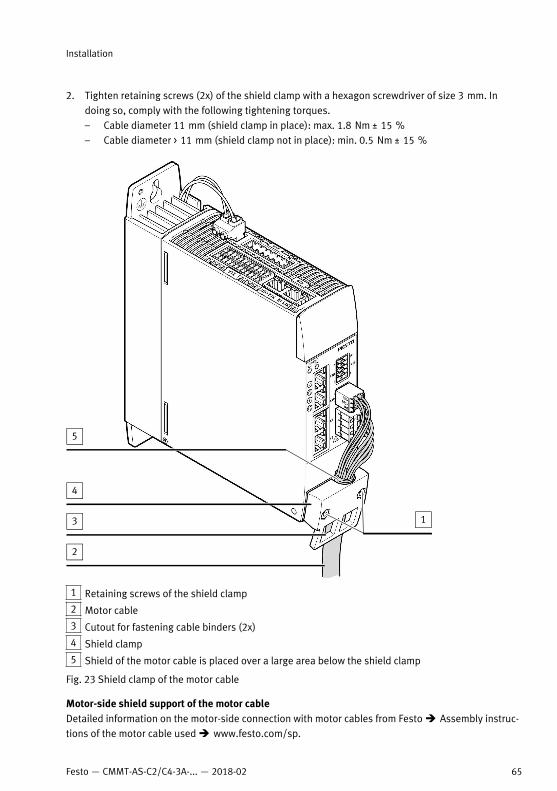
2. Tighten retaining screws (2x) of the shield clamp with a hexagon screwdriver of size 3 mm. Indoing so, comply with the following tightening torques.– Cable diameter 11 mm (shield clamp in place): max. 1.8 Nm ± 15 %– Cable diameter > 11 mm (shield clamp not in place): min. 0.5 Nm ± 15 %
1 Retaining screws of the shield clamp
2 Motor cable
3 Cutout for fastening cable binders (2x)
4 Shield clamp
5 Shield of the motor cable is placed over a large area below the shield clamp
Fig. 23 Shield clamp of the motor cable
Motor-side shield support of the motor cableDetailed information on the motor-side connection with motor cables from Festo è Assembly instruc-tions of the motor cable used è www.festo.com/sp.
Installation
65Festo — CMMT-AS-C2/C4-3A-... — 2018-02
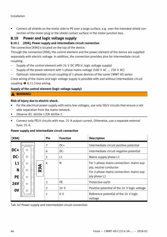
• Connect all shields on the motor side to PE over a large surface, e.g. over the intended shield con-nection of the motor plug or the shield contact surface in the motor junction box.
8.10 Power and logic voltage supply8.10.1 [X9A], Power supply and intermediate circuit connectionThe connection [X9A] is located on the top of the device.Through the connection [X9A], the control element and the power element of the device are suppliedseparately with electric voltage. In addition, the connection provides pins for intermediate circuitcoupling.– Supply of the control element with 24 V DC (PELV, logic voltage supply)– Supply of the power element with 1-phase mains voltage (100 V AC … 230 V AC)– Optional: intermediate circuit coupling of 1-phase devices of the same CMMT-AS seriesCross wiring of the mains and logic voltage supply is possible with and without intermediate circuitcoupling è 8.11 Cross wiring.
Supply of the control element (logic voltage supply)
WARNING!
Risk of injury due to electric shock.• For the electrical power supply with extra-low voltages, use only SELV circuits that ensure a reli-
able separation from the mains network.• Observe IEC 60204-1/EN 60204-1.
• Connect only PELV circuits with max. 25 A output current. Otherwise, use a separate externalfuse: 25 A.
Power supply and intermediate circuit connection
[X9A] Pin Function Description
7 DC+ Intermediate circuit positive potential
6 DC- Intermediate circuit negative potential
5 L1 Mains supply phase L1
4 N For 1-phase mains connection: mains sup-ply, neutral conductorFor 2-phase mains connection: mains sup-ply phase L2
3 PE Protective earth
2 24 V Positive potential of the 24 V logic voltage
1 0 V Reference potential of the 24 V logicvoltage
Tab. 62 Power supply and intermediate circuit connection
Installation
66 Festo — CMMT-AS-C2/C4-3A-... — 2018-02
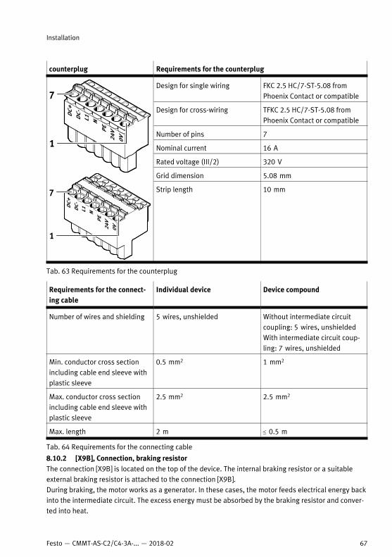
counterplug Requirements for the counterplug
Design for single wiring FKC 2.5 HC/7-ST-5.08 fromPhoenix Contact or compatible
Design for cross-wiring TFKC 2.5 HC/7-ST-5.08 fromPhoenix Contact or compatible
Number of pins 7
Nominal current 16 A
Rated voltage (III/2) 320 V
Grid dimension 5.08 mm
Strip length 10 mm
Tab. 63 Requirements for the counterplug
Requirements for the connect-ing cable
Individual device Device compound
Number of wires and shielding 5 wires, unshielded Without intermediate circuitcoupling: 5 wires, unshieldedWith intermediate circuit coup-ling: 7 wires, unshielded
Min. conductor cross sectionincluding cable end sleeve withplastic sleeve
0.5 mm2 1 mm2
Max. conductor cross sectionincluding cable end sleeve withplastic sleeve
2.5 mm2 2.5 mm2
Max. length 2 m £ 0.5 m
Tab. 64 Requirements for the connecting cable
8.10.2 [X9B], Connection, braking resistorThe connection [X9B] is located on the top of the device. The internal braking resistor or a suitableexternal braking resistor is attached to the connection [X9B].During braking, the motor works as a generator. In these cases, the motor feeds electrical energy backinto the intermediate circuit. The excess energy must be absorbed by the braking resistor and conver-ted into heat.
Installation
67Festo — CMMT-AS-C2/C4-3A-... — 2018-02
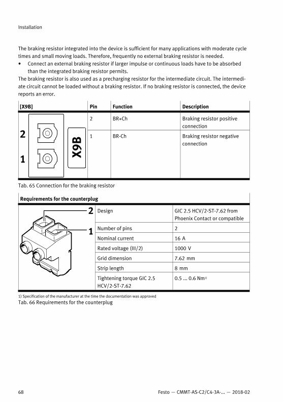
The braking resistor integrated into the device is sufficient for many applications with moderate cycletimes and small moving loads. Therefore, frequently no external braking resistor is needed.• Connect an external braking resistor if larger impulse or continuous loads have to be absorbed
than the integrated braking resistor permits.The braking resistor is also used as a precharging resistor for the intermediate circuit. The intermedi-ate circuit cannot be loaded without a braking resistor. If no braking resistor is connected, the devicereports an error.
[X9B] Pin Function Description
2 BR+Ch Braking resistor positiveconnection
1 BR-Ch Braking resistor negativeconnection
Tab. 65 Connection for the braking resistor
Requirements for the counterplug
Design GIC 2.5 HCV/2-ST-7.62 fromPhoenix Contact or compatible
Number of pins 2
Nominal current 16 A
Rated voltage (III/2) 1000 V
Grid dimension 7.62 mm
Strip length 8 mm
Tightening torque GIC 2.5HCV/2-ST-7.62
0.5 ... 0.6 Nm1)
1) Specification of the manufacturer at the time the documentation was approved
Tab. 66 Requirements for the counterplug
Installation
68 Festo — CMMT-AS-C2/C4-3A-... — 2018-02
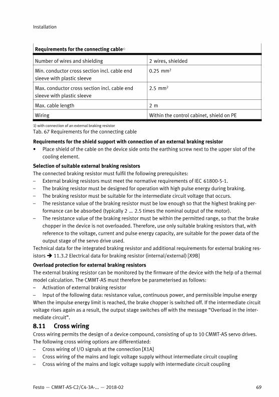
Requirements for the connecting cable1)
Number of wires and shielding 2 wires, shielded
Min. conductor cross section incl. cable endsleeve with plastic sleeve
0.25 mm2
Max. conductor cross section incl. cable endsleeve with plastic sleeve
2.5 mm2
Max. cable length 2 m
Wiring Within the control cabinet, shield on PE
1) with connection of an external braking resistor
Tab. 67 Requirements for the connecting cable
Requirements for the shield support with connection of an external braking resistor• Place shield of the cable on the device side onto the earthing screw next to the upper slot of the
cooling element.
Selection of suitable external braking resistorsThe connected braking resistor must fulfil the following prerequisites:– External braking resistors must meet the normative requirements of IEC 61800-5-1.– The braking resistor must be designed for operation with high pulse energy during braking.– The braking resistor must be suitable for the intermediate circuit voltage that occurs.– The resistance value of the braking resistor must be low enough so that the highest braking per-
formance can be absorbed (typically 2 … 2.5 times the nominal output of the motor).– The resistance value of the braking resistor must be within the permitted range, so that the brake
chopper in the device is not overloaded. Therefore, use only suitable braking resistors that, withreference to the voltage, current and pulse energy capacity, are suitable for the power data of theoutput stage of the servo drive used.
Technical data for the integrated braking resistor and additional requirements for external braking res-istors è 11.3.2 Electrical data for braking resistor (internal/external) [X9B]
Overload protection for external braking resistorsThe external braking resistor can be monitored by the firmware of the device with the help of a thermalmodel calculation. The CMMT-AS must therefore be parameterised as follows:– Activation of external braking resistor– Input of the following data: resistance value, continuous power, and permissible impulse energyWhen the impulse energy limit is reached, the brake chopper is switched off. If the intermediate circuitvoltage rises again as a result, the output stage switches off with the message “Overload in the inter-mediate circuit”.
8.11 Cross wiringCross wiring permits the design of a device compound, consisting of up to 10 CMMT-AS servo drives.The following cross wiring options are differentiated:– Cross wiring of I/O signals at the connection [X1A]– Cross wiring of the mains and logic voltage supply without intermediate circuit coupling– Cross wiring of the mains and logic voltage supply with intermediate circuit coupling
Installation
69Festo — CMMT-AS-C2/C4-3A-... — 2018-02
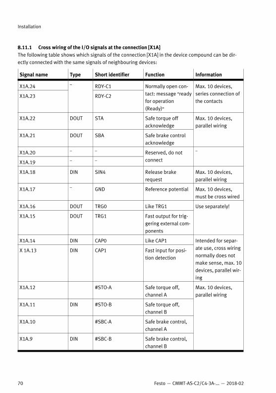
8.11.1 Cross wiring of the I/O signals at the connection [X1A]The following table shows which signals of the connection [X1A] in the device compound can be dir-ectly connected with the same signals of neighbouring devices:
Signal name Type Short identifier Function Information
X1A.24 RDY-C1
X1A.23
–
RDY-C2
Normally open con-tact: message ”readyfor operation(Ready)“
Max. 10 devices,series connection ofthe contacts
X1A.22 DOUT STA Safe torque offacknowledge
X1A.21 DOUT SBA Safe brake controlacknowledge
Max. 10 devices,parallel wiring
X1A.20 – –
X1A.19 – –
Reserved, do notconnect
–
X1A.18 DIN SIN4 Release brakerequest
Max. 10 devices,parallel wiring
X1A.17 – GND Reference potential Max. 10 devices,must be cross wired
X1A.16 DOUT TRG0 Like TRG1
X1A.15 DOUT TRG1 Fast output for trig-gering external com-ponents
Use separately!
X1A.14 DIN CAP0 Like CAP1
X 1A.13 DIN CAP1 Fast input for posi-tion detection
Intended for separ-ate use, cross wiringnormally does notmake sense, max. 10devices, parallel wir-ing
X1A.12 #STO-A Safe torque off,channel A
X1A.11 DIN #STO-B Safe torque off,channel B
X1A.10 #SBC-A Safe brake control,channel A
X1A.9 DIN #SBC-B Safe brake control,channel B
Max. 10 devices,parallel wiring
Installation
70 Festo — CMMT-AS-C2/C4-3A-... — 2018-02
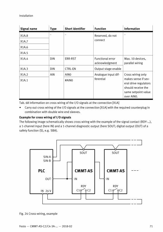
Signal name Type Short identifier Function Information
X1A.8
X1A.7
X1A.6
X1A.5
– – Reserved, do notconnect
–
X1A.4 DIN ERR-RST Functional erroracknowledgment
X1A.3 DIN CTRL-EN Output stage enable
Max. 10 devices,parallel wiring
X1A.2 AIN0
X1A.1
AIN
#AIN0
Analogue input dif-ferential
Cross wiring onlymakes sense if sev-eral drive regulatorsshould receive thesame setpoint valueover AIN0.
Tab. 68 Information on cross wiring of the I/O signals at the connection [X1A]
• Carry out cross wiring of the I/O signals at the connection [X1A] with the required counterplug incombination with double wire end sleeves.
Example for cross wiring of I/O signalsThe following image schematically shows cross wiring with the example of the signal contact (RDY-…),a 1-channel input (here IN) and a 1-channel diagnostic output (here SOUT; digital output (OUT) of asafety function (S), e.g. SBA).
Fig. 24 Cross-wiring, example
Installation
71Festo — CMMT-AS-C2/C4-3A-... — 2018-02
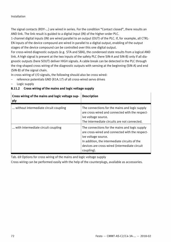
The signal contacts (RDY-...) are wired in series. For the condition “Contact closed”, there results anAND link. The link result is guided to a digital input (IN) of the higher-order PLC.1-channel digital inputs (IN) are wired parallel to an output (OUT) of the PLC. If, for example, all CTRL-EN inputs of the device compound are wired in parallel to a digital output, enabling of the outputstages of the device compound can be controlled over this one digital output.For cross-wired diagnostic outputs (e.g. STA and SBA), the condensed state results from a logical ANDlink. A high signal is present at the two inputs of the safety PLC (here SIN-A and SIN-B) only if all dia-gnostic outputs (here SOUT) deliver HIGH signals. A cable break can be detected in the PLC throughthe ring-shaped cross wiring of the diagnostic outputs with sensing at the beginning (SIN-A) and end(SIN-B) of the signal chain.In cross wiring of I/O signals, the following should also be cross wired:– reference potentials GND (X1A.17) of all cross-wired servo drives– Logic supply8.11.2 Cross wiring of the mains and logic voltage supply
Cross wiring of the mains and logic voltage sup-ply
Description
... without intermediate circuit coupling The connections for the mains and logic supplyare cross-wired and connected with the respect-ive voltage source.The intermediate circuits are not connected.
... with intermediate circuit coupling The connections for the mains and logic supplyare cross-wired and connected with the respect-ive voltage source. In addition, the intermediate circuits of thedevices are cross-wired (intermediate circuitcoupling).
Tab. 69 Options for cross wiring of the mains and logic voltage supply
Cross wiring can be performed easily with the help of the counterplugs, available as accessories.
Installation
72 Festo — CMMT-AS-C2/C4-3A-... — 2018-02
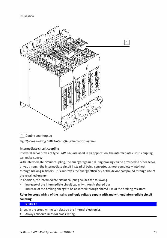
1 Double counterplug
Fig. 25 Cross-wiring CMMT-AS-...-3A (schematic diagram)
Intermediate circuit couplingIf several servo drives of type CMMT-AS are used in an application, the intermediate circuit couplingcan make sense.With intermediate circuit coupling, the energy regained during braking can be provided to other servodrives through the intermediate circuit instead of being converted almost completely into heatthrough braking resistors. This improves the energy efficiency of the device compound through use ofthe regained energy.In addition, the intermediate circuit coupling causes the following:– increase of the intermediate circuit capacity through shared use– increase of the braking energy to be absorbed through shared use of the braking resistors
Rules for cross wiring of the mains and logic voltage supply with and without intermediate circuitcoupling
NOTICE!
Errors in the cross wiring can destroy the internal electronics.• Always observe rules for cross wiring.
Installation
73Festo — CMMT-AS-C2/C4-3A-... — 2018-02
– Only cross wire devices with the same mains voltage. The devices may therefore either be 1-phasedevices or only 3-phase devices with the same mains voltage supply and intermediate circuitvoltage. Cross wiring of the mains and logic voltage supply between 1-phase devices and 3-phasedevices is not permitted and results directly in destruction of the servo drive!
– For 1-phase devices: Connect all devices to the same mains phase.– For 3-phase devices: Connect all devices to the same 3 mains phases.– Place devices with greater power use closer to the mains infeed.– Insert a suitable fuse into the mains supply line for line protection and semiconductor protection.– Do not exceed the maximum number of devices in the device compound.
A device compound may consist of a maximum of 10 devices. But the permitted number isdependent on the output data of the devices used and the parameterised nominal currents of theconnected motors. The number is limited by the amount of the maximum permitted total currentand the maximum permitted total nominal power (dependent on the conductor cross section ofthe cross wiring).
– Always connect all devices with the mains supply, even with intermediate circuit coupling. It is notpermitted to connect only one device or only one part of the device compound to the mains sup-ply. Such wiring can overload and destroy devices.
Braking resistors in the device compound– A braking resistor must be attached to each device in the device compound (internal or external).– If devices with different output power are combined, dimension the braking resistors appropri-
ately to the output power of the devices. This is ensured if the internal braking resistors are used.
Electrical protection of a device compoundA shared external fuse is required at the mains connection of the devices. The fuse fulfils the followingfunctions:– Cable protection; the rated current of the fuse must be less than or equal to the permissible cur-
rent carrying capacity of the selected conductor cross section.– Semiconductor protection; the diode rectifiers of the devices are not protected against short cir-
cuit currents in the DC intermediate circuit.Recommendation:– Use circuit breakers as line protection with appropriate tripping current and switching character-
istics C. For additional information è 8.3 Mains fuse.
Data for operation in the device compound (CMMT-AS-...-3A)A device compound may consist of a maximum of 10 devices. But the permitted number is dependenton the output data of the devices used.The number is limited by the amount of the maximum permitted total current and the maximum per-mitted total nominal power of the device compound and depends on the conductor cross section.
Choice of mains protection1. Determine total mains current of the device compound.2. Determine total current of the logic supply.3. Select the required conductor cross section for the cross wiring.4. Required mains protection, considering the conductor cross section and the standard classifica-
tion (according to UL or IEC).Permissible maximum values è Tab. 14 Mains fuse.
Installation
74 Festo — CMMT-AS-C2/C4-3A-... — 2018-02
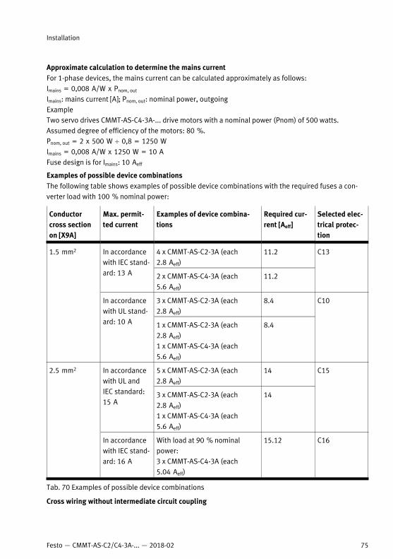
Approximate calculation to determine the mains currentFor 1-phase devices, the mains current can be calculated approximately as follows:Imains = 0,008 A/W x Pnom, out
Imains: mains current [A]; Pnom, out: nominal power, outgoingExampleTwo servo drives CMMT-AS-C4-3A-... drive motors with a nominal power (Pnom) of 500 watts.Assumed degree of efficiency of the motors: 80 %.Pnom, out = 2 x 500 W ¸ 0,8 = 1250 WImains = 0,008 A/W x 1250 W = 10 AFuse design is for Imains: 10 Aeff
Examples of possible device combinationsThe following table shows examples of possible device combinations with the required fuses a con-verter load with 100 % nominal power:
Conductorcross sectionon [X9A]
Max. permit-ted current
Examples of device combina-tions
Required cur-rent [Aeff]
Selected elec-trical protec-tion
4 x CMMT-AS-C2-3A (each2.8 Aeff)
11.2In accordancewith IEC stand-ard: 13 A 2 x CMMT-AS-C4-3A (each
5.6 Aeff)11.2
C13
3 x CMMT-AS-C2-3A (each2.8 Aeff)
8.4
1.5 mm2
In accordancewith UL stand-ard: 10 A 1 x CMMT-AS-C2-3A (each
2.8 Aeff)1 x CMMT-AS-C4-3A (each5.6 Aeff)
8.4
C10
5 x CMMT-AS-C2-3A (each2.8 Aeff)
14In accordancewith UL andIEC standard:15 A
3 x CMMT-AS-C2-3A (each2.8 Aeff)1 x CMMT-AS-C4-3A (each5.6 Aeff)
14
C152.5 mm2
In accordancewith IEC stand-ard: 16 A
With load at 90 % nominalpower: 3 x CMMT-AS-C4-3A (each5.04 Aeff)
15.12 C16
Tab. 70 Examples of possible device combinations
Cross wiring without intermediate circuit coupling
Installation
75Festo — CMMT-AS-C2/C4-3A-... — 2018-02
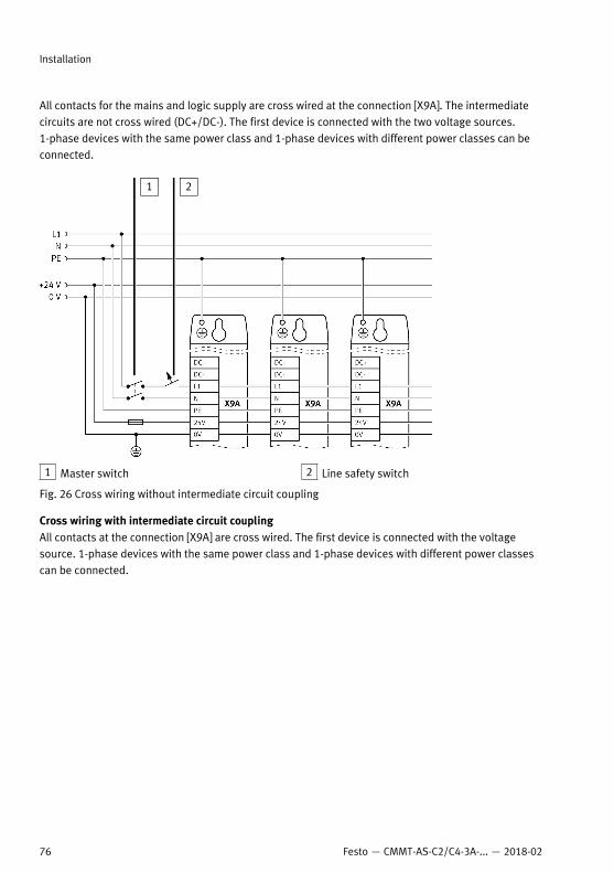
All contacts for the mains and logic supply are cross wired at the connection [X9A]. The intermediatecircuits are not cross wired (DC+/DC-). The first device is connected with the two voltage sources.1-phase devices with the same power class and 1-phase devices with different power classes can beconnected.
1 Master switch 2 Line safety switch
Fig. 26 Cross wiring without intermediate circuit coupling
Cross wiring with intermediate circuit couplingAll contacts at the connection [X9A] are cross wired. The first device is connected with the voltagesource. 1-phase devices with the same power class and 1-phase devices with different power classescan be connected.
Installation
76 Festo — CMMT-AS-C2/C4-3A-... — 2018-02
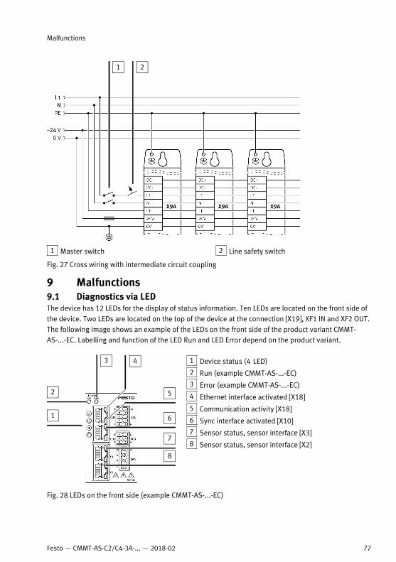
1 Master switch 2 Line safety switch
Fig. 27 Cross wiring with intermediate circuit coupling
9 Malfunctions9.1 Diagnostics via LEDThe device has 12 LEDs for the display of status information. Ten LEDs are located on the front side ofthe device. Two LEDs are located on the top of the device at the connection [X19], XF1 IN and XF2 OUT.The following image shows an example of the LEDs on the front side of the product variant CMMT-AS-...-EC. Labelling and function of the LED Run and LED Error depend on the product variant.
1 Device status (4 LED)
2 Run (example CMMT-AS-...-EC)
3 Error (example CMMT-AS-...-EC)
4 Ethernet interface activated [X18]
5 Communication activity [X18]
6 Sync interface activated [X10]
7 Sensor status, sensor interface [X3]
8 Sensor status, sensor interface [X2]
Fig. 28 LEDs on the front side (example CMMT-AS-...-EC)
Malfunctions
77Festo — CMMT-AS-C2/C4-3A-... — 2018-02
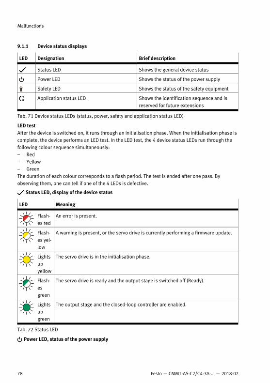
9.1.1 Device status displays
LED Designation Brief description
Status LED Shows the general device status
Power LED Shows the status of the power supply
Safety LED Shows the status of the safety equipment
Application status LED Shows the identification sequence and isreserved for future extensions
Tab. 71 Device status LEDs (status, power, safety and application status LED)
LED testAfter the device is switched on, it runs through an initialisation phase. When the initialisation phase iscomplete, the device performs an LED test. In the LED test, the 4 device status LEDs run through thefollowing colour sequence simultaneously:– Red– Yellow– GreenThe duration of each colour corresponds to a flash period. The test is ended after one pass. Byobserving them, one can tell if one of the 4 LEDs is defective.
Status LED, display of the device status
LED Meaning
Flash-es red
An error is present.
Flash-es yel-low
A warning is present, or the servo drive is currently performing a firmware update.
Lightsupyellow
The servo drive is in the initialisation phase.
Flash-esgreen
The servo drive is ready and the output stage is switched off (Ready).
Lightsupgreen
The output stage and the closed-loop controller are enabled.
Tab. 72 Status LED
Power LED, status of the power supply
Malfunctions
78 Festo — CMMT-AS-C2/C4-3A-... — 2018-02
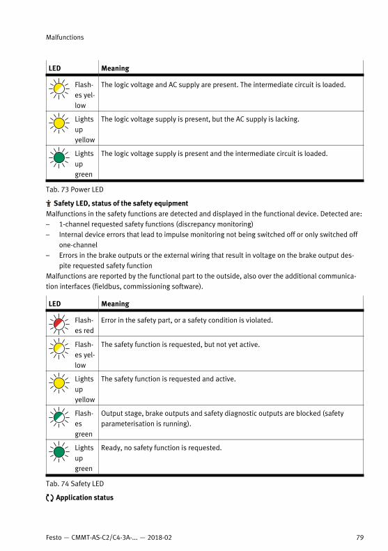
LED Meaning
Flash-es yel-low
The logic voltage and AC supply are present. The intermediate circuit is loaded.
Lightsupyellow
The logic voltage supply is present, but the AC supply is lacking.
Lightsupgreen
The logic voltage supply is present and the intermediate circuit is loaded.
Tab. 73 Power LED
Safety LED, status of the safety equipmentMalfunctions in the safety functions are detected and displayed in the functional device. Detected are:– 1-channel requested safety functions (discrepancy monitoring)– Internal device errors that lead to impulse monitoring not being switched off or only switched off
one-channel– Errors in the brake outputs or the external wiring that result in voltage on the brake output des-
pite requested safety functionMalfunctions are reported by the functional part to the outside, also over the additional communica-tion interfaces (fieldbus, commissioning software).
LED Meaning
Flash-es red
Error in the safety part, or a safety condition is violated.
Flash-es yel-low
The safety function is requested, but not yet active.
Lightsupyellow
The safety function is requested and active.
Flash-esgreen
Output stage, brake outputs and safety diagnostic outputs are blocked (safetyparameterisation is running).
Lightsupgreen
Ready, no safety function is requested.
Tab. 74 Safety LED
Application status
Malfunctions
79Festo — CMMT-AS-C2/C4-3A-... — 2018-02
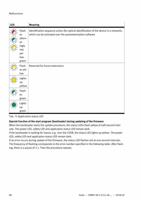
LED Meaning
Flash-esaltern-at-inglyred,yel-low,green
Identification sequence active (for optical identification of the device in a network),which can be activated over the parameterisation software
Flash-es yel-low
Lightsupyellow
Flash-esgreen
Lightsupgreen
Reserved for future extensions
Tab. 75 Application status LED
Special function of the start program (bootloader) during updating of the firmwareWhen the bootloader starts the update procedure, the status LEDs flash yellow at half-second inter-vals. The power LED, safety LED and application status LED remain dark.If the bootloader is waiting for inputs, e.g. over the CDSB, the status LED lights up yellow. The powerLED, safety LED and application status LED remain dark.If an error occurs during update of the firmware, the status LED flashes red at one-second intervals.The frequency of flashing corresponds to the error number specified in the following table. After flash-ing, there is a pause of 3 s. Then the procedure repeats.
Malfunctions
80 Festo — CMMT-AS-C2/C4-3A-... — 2018-02
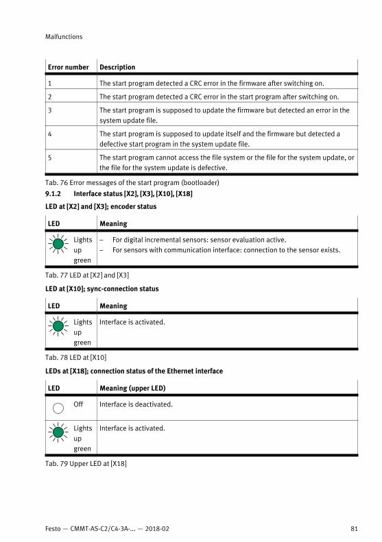
Error number Description
1 The start program detected a CRC error in the firmware after switching on.
2 The start program detected a CRC error in the start program after switching on.
3 The start program is supposed to update the firmware but detected an error in thesystem update file.
4 The start program is supposed to update itself and the firmware but detected adefective start program in the system update file.
5 The start program cannot access the file system or the file for the system update, orthe file for the system update is defective.
Tab. 76 Error messages of the start program (bootloader)
9.1.2 Interface status [X2], [X3], [X10], [X18]
LED at [X2] and [X3]; encoder status
LED Meaning
Lightsupgreen
– For digital incremental sensors: sensor evaluation active.– For sensors with communication interface: connection to the sensor exists.
Tab. 77 LED at [X2] and [X3]
LED at [X10]; sync-connection status
LED Meaning
Lightsupgreen
Interface is activated.
Tab. 78 LED at [X10]
LEDs at [X18]; connection status of the Ethernet interface
LED Meaning (upper LED)
Off Interface is deactivated.
Lightsupgreen
Interface is activated.
Tab. 79 Upper LED at [X18]
Malfunctions
81Festo — CMMT-AS-C2/C4-3A-... — 2018-02
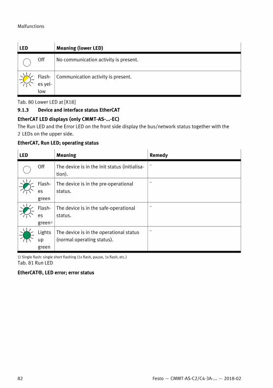
LED Meaning (lower LED)
Off No communication activity is present.
Flash-es yel-low
Communication activity is present.
Tab. 80 Lower LED at [X18]
9.1.3 Device and interface status EtherCAT
EtherCAT LED displays (only CMMT-AS-...-EC)The Run LED and the Error LED on the front side display the bus/network status together with the2 LEDs on the upper side.
EtherCAT, Run LED; operating status
LED Meaning Remedy
Off The device is in the Init status (initialisa-tion).
–
Flash-esgreen
The device is in the pre-operationalstatus.
–
Flash-esgreen1)
The device is in the safe-operationalstatus.
–
Lightsupgreen
The device is in the operational status(normal operating status).
–
1) Single flash: single short flashing (1x flash, pause, 1x flash, etc.)
Tab. 81 Run LED
EtherCAT®, LED error; error status
Malfunctions
82 Festo — CMMT-AS-C2/C4-3A-... — 2018-02
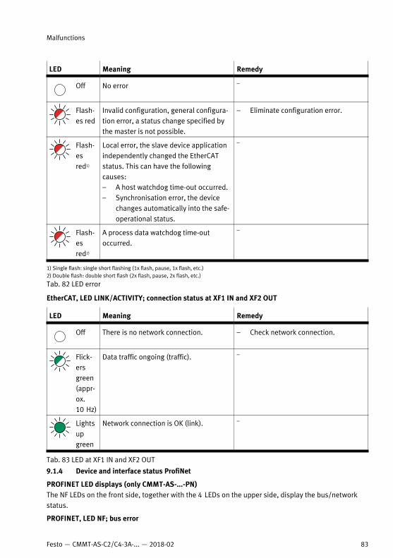
LED Meaning Remedy
Off No error –
Flash-es red
Invalid configuration, general configura-tion error, a status change specified bythe master is not possible.
– Eliminate configuration error.
Flash-esred1)
Local error, the slave device applicationindependently changed the EtherCATstatus. This can have the followingcauses:– A host watchdog time-out occurred.– Synchronisation error, the device
changes automatically into the safe-operational status.
–
Flash-esred2)
A process data watchdog time-outoccurred.
–
1) Single flash: single short flashing (1x flash, pause, 1x flash, etc.)2) Double flash: double short flash (2x flash, pause, 2x flash, etc.)
Tab. 82 LED error
EtherCAT, LED LINK/ACTIVITY; connection status at XF1 IN and XF2 OUT
LED Meaning Remedy
Off There is no network connection. – Check network connection.
Flick-ersgreen(appr-ox.10 Hz)
Data traffic ongoing (traffic). –
Lightsupgreen
Network connection is OK (link). –
Tab. 83 LED at XF1 IN and XF2 OUT
9.1.4 Device and interface status ProfiNet
PROFINET LED displays (only CMMT-AS-...-PN)The NF LEDs on the front side, together with the 4 LEDs on the upper side, display the bus/networkstatus.
PROFINET, LED NF; bus error
Malfunctions
83Festo — CMMT-AS-C2/C4-3A-... — 2018-02
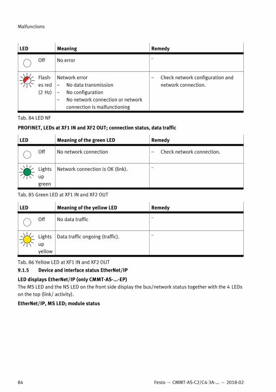
LED Meaning Remedy
Off No error –
Flash-es red(2 Hz)
Network error– No data transmission– No configuration– No network connection or network
connection is malfunctioning
– Check network configuration andnetwork connection.
Tab. 84 LED NF
PROFINET, LEDs at XF1 IN and XF2 OUT; connection status, data traffic
LED Meaning of the green LED Remedy
Off No network connection – Check network connection.
Lightsupgreen
Network connection is OK (link). –
Tab. 85 Green LED at XF1 IN and XF2 OUT
LED Meaning of the yellow LED Remedy
Off No data traffic –
Lightsupyellow
Data traffic ongoing (traffic). –
Tab. 86 Yellow LED at XF1 IN and XF2 OUT
9.1.5 Device and interface status EtherNet/IP
LED displays EtherNet/IP (only CMMT-AS-...-EP)The MS LED and the NS LED on the front side display the bus/network status together with the 4 LEDson the top (link/ activity).
EtherNet/IP, MS LED; module status
Malfunctions
84 Festo — CMMT-AS-C2/C4-3A-... — 2018-02
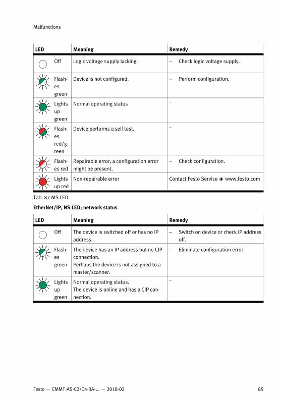
LED Meaning Remedy
Off Logic voltage supply lacking. – Check logic voltage supply.
Flash-esgreen
Device is not configured. – Perform configuration.
Lightsupgreen
Normal operating status –
Flash-esred/g-reen
Device performs a self test. –
Flash-es red
Repairable error, a configuration errormight be present.
– Check configuration.
Lightsup red
Non-repairable error Contact Festo Service è www.festo.com
Tab. 87 MS LED
EtherNet/IP, NS LED; network status
LED Meaning Remedy
Off The device is switched off or has no IPaddress.
– Switch on device or check IP addressoff.
Flash-esgreen
The device has an IP address but no CIPconnection.Perhaps the device is not assigned to amaster/scanner.
– Eliminate configuration error.
Lightsupgreen
Normal operating status.The device is online and has a CIP con-nection.
–
Malfunctions
85Festo — CMMT-AS-C2/C4-3A-... — 2018-02
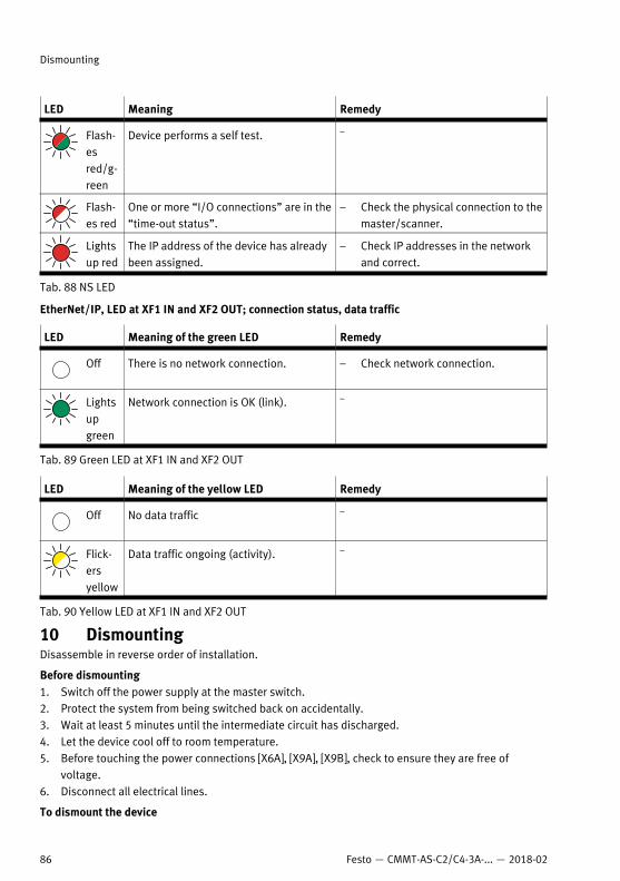
LED Meaning Remedy
Flash-esred/g-reen
Device performs a self test. –
Flash-es red
One or more “I/O connections” are in the“time-out status”.
– Check the physical connection to themaster/scanner.
Lightsup red
The IP address of the device has alreadybeen assigned.
– Check IP addresses in the networkand correct.
Tab. 88 NS LED
EtherNet/IP, LED at XF1 IN and XF2 OUT; connection status, data traffic
LED Meaning of the green LED Remedy
Off There is no network connection. – Check network connection.
Lightsupgreen
Network connection is OK (link). –
Tab. 89 Green LED at XF1 IN and XF2 OUT
LED Meaning of the yellow LED Remedy
Off No data traffic –
Flick-ersyellow
Data traffic ongoing (activity). –
Tab. 90 Yellow LED at XF1 IN and XF2 OUT
10 DismountingDisassemble in reverse order of installation.
Before dismounting1. Switch off the power supply at the master switch.2. Protect the system from being switched back on accidentally.3. Wait at least 5 minutes until the intermediate circuit has discharged. 4. Let the device cool off to room temperature.5. Before touching the power connections [X6A], [X9A], [X9B], check to ensure they are free of
voltage.6. Disconnect all electrical lines.
To dismount the device
Dismounting
86 Festo — CMMT-AS-C2/C4-3A-... — 2018-02
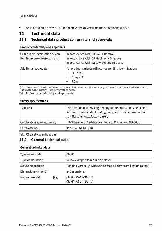
• Loosen retaining screws (2x) and remove the device from the attachment surface.
11 Technical data11.1 Technical data product conformity and approvals
Product conformity and approvals
CE marking (declaration of con-formity è www.festo.com/sp)
In accordance with EU-EMC Directive1)
In accordance with EU Machinery DirectiveIn accordance with EU Low Voltage Directive
Additional approvals For product variants with corresponding identification:– UL/NEC– CSA/NEC– RCM
1) The component is intended for industrial use. Outside of industrial environments, e.g. in commercial and mixed-residential areas,actions to suppress interference may have to be taken.
Tab. 91 Product conformity and approvals
Safety specifications
Type test The functional safety engineering of the product has been certi-fied by an independent testing body, see EC-type examinationcertificate è www.festo.com/sp
Certificate issuing authority TÜV Rheinland, Certification Body of Machinery, NB 0035
Certificate no. 01/205/5640.00/18
Tab. 92 Safety specifications
11.2 General technical data
General technical data
Type name code CMMT
Type of mounting Screw-clamped to mounting plate
Mounting position Hanging vertically, with unhindered air flow from bottom to top
Dimensions (H*W*D) è Dimensions
Product weight [kg] CMMT-AS-C2-3A: 1.3CMMT-AS-C4-3A: 1.4
Technical data
87Festo — CMMT-AS-C2/C4-3A-... — 2018-02
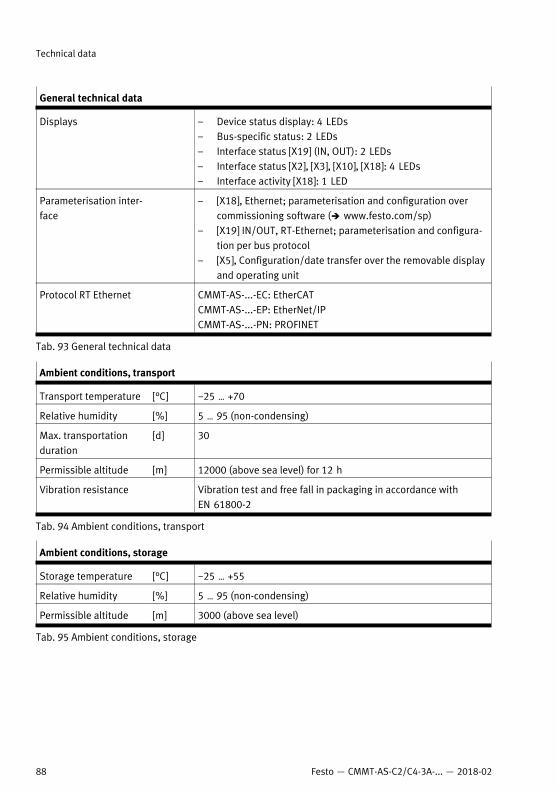
General technical data
Displays – Device status display: 4 LEDs– Bus-specific status: 2 LEDs– Interface status [X19] (IN, OUT): 2 LEDs– Interface status [X2], [X3], [X10], [X18]: 4 LEDs– Interface activity [X18]: 1 LED
Parameterisation inter-face
– [X18], Ethernet; parameterisation and configuration overcommissioning software (è www.festo.com/sp)
– [X19] IN/OUT, RT-Ethernet; parameterisation and configura-tion per bus protocol
– [X5], Configuration/date transfer over the removable displayand operating unit
Protocol RT Ethernet CMMT-AS-...-EC: EtherCATCMMT-AS-...-EP: EtherNet/IPCMMT-AS-...-PN: PROFINET
Tab. 93 General technical data
Ambient conditions, transport
Transport temperature [°C] −25 … +70
Relative humidity [%] 5 … 95 (non-condensing)
Max. transportationduration
[d] 30
Permissible altitude [m] 12000 (above sea level) for 12 h
Vibration resistance Vibration test and free fall in packaging in accordance withEN 61800-2
Tab. 94 Ambient conditions, transport
Ambient conditions, storage
Storage temperature [°C] −25 … +55
Relative humidity [%] 5 … 95 (non-condensing)
Permissible altitude [m] 3000 (above sea level)
Tab. 95 Ambient conditions, storage
Technical data
88 Festo — CMMT-AS-C2/C4-3A-... — 2018-02
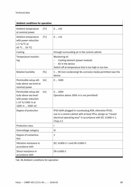
Ambient conditions for operation
Ambient temperatureat nominal power
[°C] 0 … +40
Ambient temperaturewith power reduction (–3 %/°C at40 °C … 50 °C)
[°C] 0 … +50
Cooling through surrounding air in the control cabinet
Temperature monitor-ing
Monitoring of:– Cooling element (power module)– Air in the deviceSwitch off at temperature that is too high or too low
Relative humidity [%] 5 … 90 (not condensing) No corrosive media permitted near thedevice
Permissible setup alti-tude above sea level atnominal power
[m] 0 … 1000
Permissible setup alti-tude above sea levelwith power reduction(–10 %/1000 m at1000 m … 2000 m)
[m] 0 … 2000Operation above 2000 m is not permitted!
Degree of protection IP20 (with plugged-in counterplug X9A, otherwise IP10); use in a control cabinet with at least IP54, design as “closedelectrical operating area” in accordance with IEC 61800-5-1,Chap.3.5
Protection class I
Overvoltage category III
Degree of contamina-tion
2
Vibration resistance inaccordance with
IEC 61800-5-1 and EN 61800-2
Shock resistance inaccordance with
EN 61800-2
Tab. 96 Ambient conditions for operation
Technical data
89Festo — CMMT-AS-C2/C4-3A-... — 2018-02
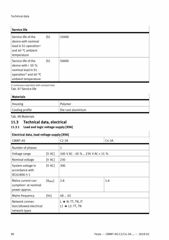
Service life
Service life of thedevice with nominalload in S1 operation1)
and 40 °C ambienttemperature
[h] 25000
Service life of thedevice with < 50 %nominal load in S1operation1) and 40 °Cambient temperature
[h] 50000
1) continuous operation with constant load
Tab. 97 Service life
Materials
Housing Polymer
Cooling profile Die-cast aluminium
Tab. 98 Materials
11.3 Technical data, electrical11.3.1 Load and logic voltage supply [X9A]
Electrical data, load voltage supply [X9A]
CMMT-AS C2-3A C4-3A
Number of phases 1
Voltage range [V AC] 100 V AC – 20 % … 230 V AC + 15 %
Nominal voltage [V AC] 230
System voltage inaccordance withIEC61800-5-1
[V AC] 300
Mains current con-sumption1) at nominalpower approx.
[ARMS] 2.8 5.6
Mains frequency [Hz] 48 … 62
Network connec-tion/allowed electricalnetwork types
L è N: TT, TN, ITL1 è L2: TT, TN
Technical data
90 Festo — CMMT-AS-C2/C4-3A-... — 2018-02
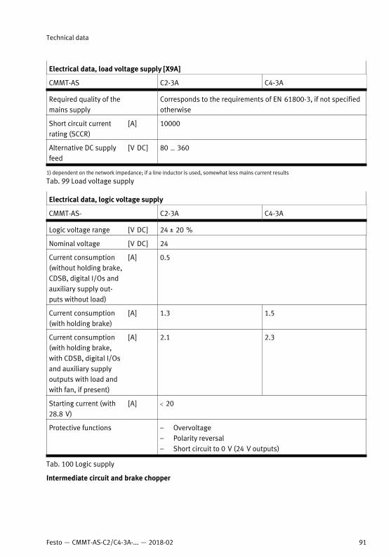
Electrical data, load voltage supply [X9A]
CMMT-AS C2-3A C4-3A
Required quality of themains supply
Corresponds to the requirements of EN 61800-3, if not specifiedotherwise
Short circuit currentrating (SCCR)
[A] 10000
Alternative DC supplyfeed
[V DC] 80 … 360
1) dependent on the network impedance; if a line inductor is used, somewhat less mains current results
Tab. 99 Load voltage supply
Electrical data, logic voltage supply
CMMT-AS- C2-3A C4-3A
Logic voltage range [V DC] 24 ± 20 %
Nominal voltage [V DC] 24
Current consumption(without holding brake,CDSB, digital I/Os andauxiliary supply out-puts without load)
[A] 0.5
Current consumption(with holding brake)
[A] 1.3 1.5
Current consumption(with holding brake,with CDSB, digital I/Osand auxiliary supplyoutputs with load andwith fan, if present)
[A] 2.1 2.3
Starting current (with28.8 V)
[A] < 20
Protective functions – Overvoltage– Polarity reversal– Short circuit to 0 V (24 V outputs)
Tab. 100 Logic supply
Intermediate circuit and brake chopper
Technical data
91Festo — CMMT-AS-C2/C4-3A-... — 2018-02
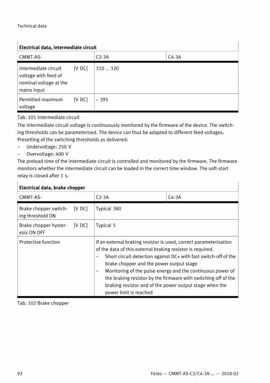
Electrical data, intermediate circuit
CMMT-AS- C2-3A C4-3A
Intermediate circuitvoltage with feed ofnominal voltage at themains input
[V DC] 310 … 320
Permitted maximumvoltage
[V DC] < 395
Tab. 101 Intermediate circuit
The intermediate circuit voltage is continuously monitored by the firmware of the device. The switch-ing thresholds can be parameterised. The device can thus be adapted to different feed voltages.Presetting of the switching thresholds as delivered:– Undervoltage: 250 V– Overvoltage: 400 VThe preload time of the intermediate circuit is controlled and monitored by the firmware. The firmwaremonitors whether the intermediate circuit can be loaded in the correct time window. The soft-startrelay is closed after 1 s.
Electrical data, brake chopper
CMMT-AS- C2-3A C4-3A
Brake chopper switch-ing threshold ON
[V DC] Typical 380
Brake chopper hyster-esis ON OFF
[V DC] Typical 5
Protective function If an external braking resistor is used, correct parameterisationof the data of this external braking resistor is required.– Short circuit detection against DC+ with fast switch-off of the
brake chopper and the power output stage– Monitoring of the pulse energy and the continuous power of
the braking resistor by the firmware with switching off of thebraking resistor and of the power output stage when thepower limit is reached
Tab. 102 Brake chopper
Technical data
92 Festo — CMMT-AS-C2/C4-3A-... — 2018-02
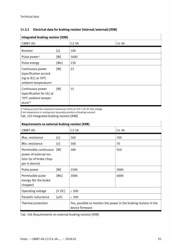
11.3.2 Electrical data for braking resistor (internal/external) [X9B]
Integrated braking resistor [X9B]
CMMT-AS- C2-3A C4-3A
Resistor [Ω] 100
Pulse power1) [W] 1600
Pulse energy [Ws] 230
Continuous power(specification accord-ing to IEC) at 70°Cambient temperature2)
[W] 23
Continuous power(specification for UL) at70°C ambient temper-ature2)
[W] 15
1) Taking account the component tolerances (10%) at 370 V DC DC-link voltage2) Air temperature in cooling duct (assembly position of braking resistor)
Tab. 103 Integrated braking resistor [X9B]
Requirements on external braking resistor [X9B]
CMMT-AS- C2-3A C4-3A
Max. resistance [Ω] 160 100
Min. resistance [Ω] 100 70
Permissible continuouspower of external res-istor (or of brake chop-per in device)
[W] 180 350
Pulse power [W] 1500 2000
Permissible pulseenergy (for the brakechopper)
[Ws] 2000 4000
Operating voltage [V DC] ³ 500
Parasitic inductance [uH] £ 200
Thermal protection Yes, possible to monitor the power in the braking resistor in thedevice firmware
Tab. 104 Requirements on external braking resistor [X9B]
Technical data
93Festo — CMMT-AS-C2/C4-3A-... — 2018-02
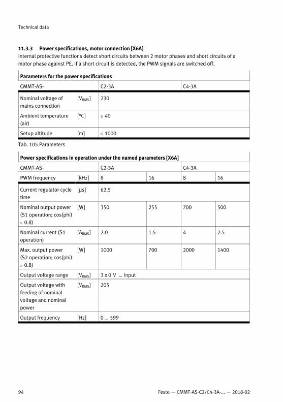
11.3.3 Power specifications, motor connection [X6A]Internal protective functions detect short circuits between 2 motor phases and short circuits of amotor phase against PE. If a short circuit is detected, the PWM signals are switched off.
Parameters for the power specifications
CMMT-AS- C2-3A C4-3A
Nominal voltage ofmains connection
[VRMS] 230
Ambient temperature(air)
[°C] £ 40
Setup altitude [m] £ 1000
Tab. 105 Parameters
Power specifications in operation under the named parameters [X6A]
CMMT-AS- C2-3A C4-3A
PWM frequency [kHz] 8 16 8 16
Current regulator cycletime
[µs] 62.5
Nominal output power(S1 operation; cos(phi)> 0.8)
[W] 350 255 700 500
Nominal current (S1operation)
[ARMS] 2.0 1.5 4 2.5
Max. output power(S2 operation; cos(phi)> 0.8)
[W] 1000 700 2000 1400
Output voltage range [VRMS] 3 x 0 V … Input
Output voltage withfeeding of nominalvoltage and nominalpower
[VRMS] 205
Output frequency [Hz] 0 … 599
Technical data
94 Festo — CMMT-AS-C2/C4-3A-... — 2018-02
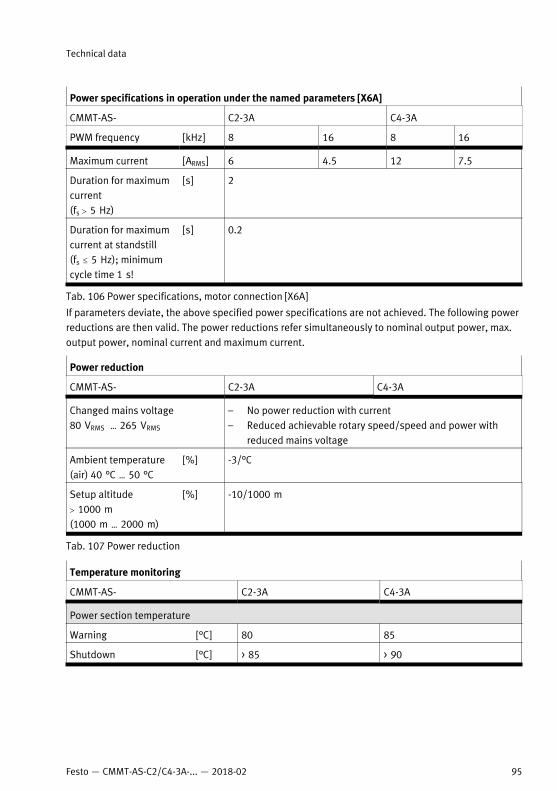
Power specifications in operation under the named parameters [X6A]
CMMT-AS- C2-3A C4-3A
PWM frequency [kHz] 8 16 8 16
Maximum current [ARMS] 6 4.5 12 7.5
Duration for maximumcurrent(fs > 5 Hz)
[s] 2
Duration for maximumcurrent at standstill(fs £ 5 Hz); minimumcycle time 1 s!
[s] 0.2
Tab. 106 Power specifications, motor connection [X6A]
If parameters deviate, the above specified power specifications are not achieved. The following powerreductions are then valid. The power reductions refer simultaneously to nominal output power, max.output power, nominal current and maximum current.
Power reduction
CMMT-AS- C2-3A C4-3A
Changed mains voltage80 VRMS … 265 VRMS
– No power reduction with current– Reduced achievable rotary speed/speed and power with
reduced mains voltage
Ambient temperature(air) 40 °C … 50 °C
[%] -3/°C
Setup altitude> 1000 m(1000 m … 2000 m)
[%] -10/1000 m
Tab. 107 Power reduction
Temperature monitoring
CMMT-AS- C2-3A C4-3A
Power section temperature
Warning [°C] 80 85
Shutdown [°C] > 85 > 90
Technical data
95Festo — CMMT-AS-C2/C4-3A-... — 2018-02
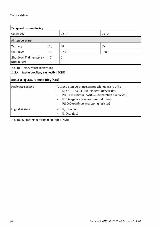
Temperature monitoring
CMMT-AS- C2-3A C4-3A
Air temperature
Warning [°C] 70 75
Shutdown [°C] > 75 > 80
Shutdown if air temperat-ure too low
[°C] 0
Tab. 108 Temperature monitoring
11.3.4 Motor auxiliary connection [X6B]
Motor temperature monitoring [X6B]
Analogue sensors Analogue temperature sensors with gain and offset – KTY 81 … 84 (silicon temperature sensors)– PTC (PTC resistor, positive temperature coefficient)– NTC (negative temperature coefficient)– Pt1000 (platinum measuring resistor)
Digital sensors – N/C contact– N/O contact
Tab. 109 Motor temperature monitoring [X6B]
Technical data
96 Festo — CMMT-AS-C2/C4-3A-... — 2018-02
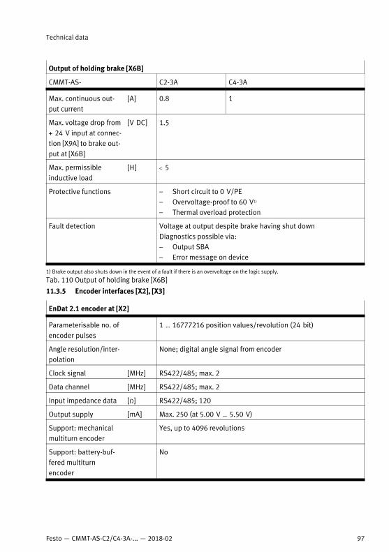
Output of holding brake [X6B]
CMMT-AS- C2-3A C4-3A
Max. continuous out-put current
[A] 0.8 1
Max. voltage drop from+ 24 V input at connec-tion [X9A] to brake out-put at [X6B]
[V DC] 1.5
Max. permissibleinductive load
[H] < 5
Protective functions – Short circuit to 0 V/PE– Overvoltage-proof to 60 V1)
– Thermal overload protection
Fault detection Voltage at output despite brake having shut downDiagnostics possible via:– Output SBA– Error message on device
1) Brake output also shuts down in the event of a fault if there is an overvoltage on the logic supply.
Tab. 110 Output of holding brake [X6B]
11.3.5 Encoder interfaces [X2], [X3]
EnDat 2.1 encoder at [X2]
Parameterisable no. ofencoder pulses
1 … 16777216 position values/revolution (24 bit)
Angle resolution/inter-polation
None; digital angle signal from encoder
Clock signal [MHz] RS422/485; max. 2
Data channel [MHz] RS422/485; max. 2
Input impedance data [Ω] RS422/485; 120
Output supply [mA] Max. 250 (at 5.00 V … 5.50 V)
Support: mechanicalmultiturn encoder
Yes, up to 4096 revolutions
Support: battery-buf-fered multiturnencoder
No
Technical data
97Festo — CMMT-AS-C2/C4-3A-... — 2018-02
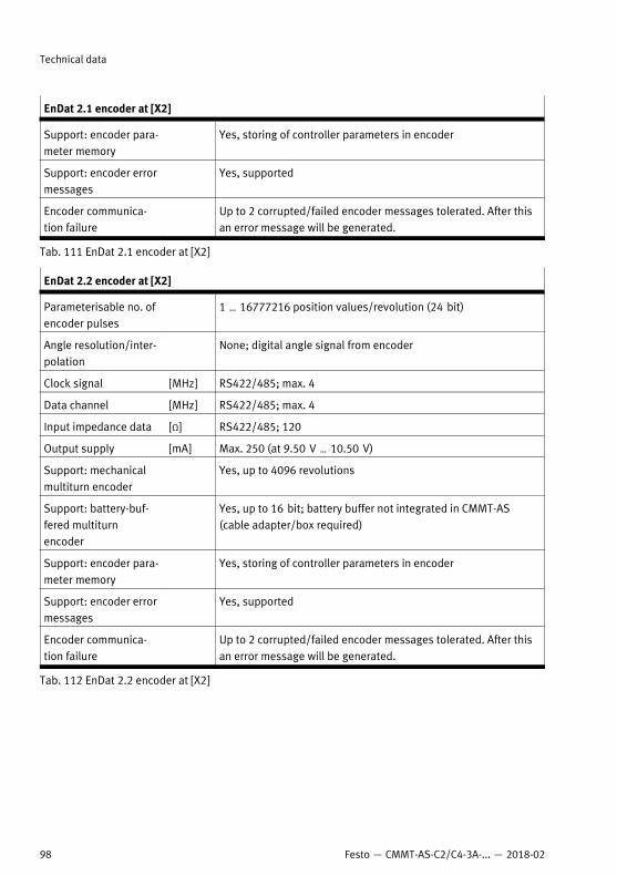
EnDat 2.1 encoder at [X2]
Support: encoder para-meter memory
Yes, storing of controller parameters in encoder
Support: encoder errormessages
Yes, supported
Encoder communica-tion failure
Up to 2 corrupted/failed encoder messages tolerated. After thisan error message will be generated.
Tab. 111 EnDat 2.1 encoder at [X2]
EnDat 2.2 encoder at [X2]
Parameterisable no. ofencoder pulses
1 … 16777216 position values/revolution (24 bit)
Angle resolution/inter-polation
None; digital angle signal from encoder
Clock signal [MHz] RS422/485; max. 4
Data channel [MHz] RS422/485; max. 4
Input impedance data [Ω] RS422/485; 120
Output supply [mA] Max. 250 (at 9.50 V … 10.50 V)
Support: mechanicalmultiturn encoder
Yes, up to 4096 revolutions
Support: battery-buf-fered multiturnencoder
Yes, up to 16 bit; battery buffer not integrated in CMMT-AS(cable adapter/box required)
Support: encoder para-meter memory
Yes, storing of controller parameters in encoder
Support: encoder errormessages
Yes, supported
Encoder communica-tion failure
Up to 2 corrupted/failed encoder messages tolerated. After thisan error message will be generated.
Tab. 112 EnDat 2.2 encoder at [X2]
Technical data
98 Festo — CMMT-AS-C2/C4-3A-... — 2018-02
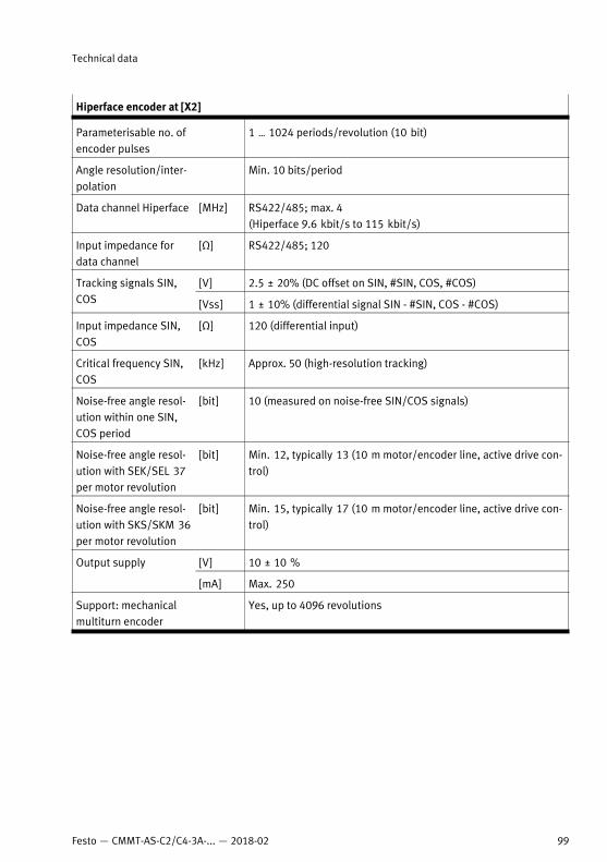
Hiperface encoder at [X2]
Parameterisable no. ofencoder pulses
1 … 1024 periods/revolution (10 bit)
Angle resolution/inter-polation
Min. 10 bits/period
Data channel Hiperface [MHz] RS422/485; max. 4(Hiperface 9.6 kbit/s to 115 kbit/s)
Input impedance fordata channel
[Ω] RS422/485; 120
[V] 2.5 ± 20% (DC offset on SIN, #SIN, COS, #COS)Tracking signals SIN,COS [Vss] 1 ± 10% (differential signal SIN - #SIN, COS - #COS)
Input impedance SIN,COS
[Ω] 120 (differential input)
Critical frequency SIN,COS
[kHz] Approx. 50 (high-resolution tracking)
Noise-free angle resol-ution within one SIN,COS period
[bit] 10 (measured on noise-free SIN/COS signals)
Noise-free angle resol-ution with SEK/SEL 37per motor revolution
[bit] Min. 12, typically 13 (10 m motor/encoder line, active drive con-trol)
Noise-free angle resol-ution with SKS/SKM 36per motor revolution
[bit] Min. 15, typically 17 (10 m motor/encoder line, active drive con-trol)
[V] 10 ± 10 %Output supply
[mA] Max. 250
Support: mechanicalmultiturn encoder
Yes, up to 4096 revolutions
Technical data
99Festo — CMMT-AS-C2/C4-3A-... — 2018-02
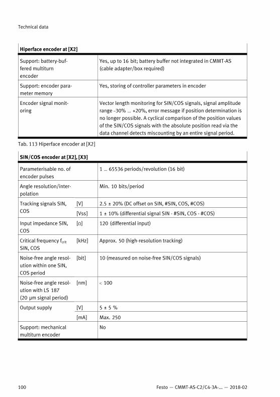
Hiperface encoder at [X2]
Support: battery-buf-fered multiturnencoder
Yes, up to 16 bit; battery buffer not integrated in CMMT-AS(cable adapter/box required)
Support: encoder para-meter memory
Yes, storing of controller parameters in encoder
Encoder signal monit-oring
Vector length monitoring for SIN/COS signals, signal amplituderange –30% ... +20%, error message if position determination isno longer possible. A cyclical comparison of the position valuesof the SIN/COS signals with the absolute position read via thedata channel detects miscounting by an entire signal period.
Tab. 113 Hiperface encoder at [X2]
SIN/COS encoder at [X2], [X3]
Parameterisable no. ofencoder pulses
1 … 65536 periods/revolution (16 bit)
Angle resolution/inter-polation
Min. 10 bits/period
[V] 2.5 ± 20% (DC offset on SIN, #SIN, COS, #COS)Tracking signals SIN,COS [Vss] 1 ± 10% (differential signal SIN - #SIN, COS - #COS)
Input impedance SIN,COS
[Ω] 120 (differential input)
Critical frequency fcrit
SIN, COS[kHz] Approx. 50 (high-resolution tracking)
Noise-free angle resol-ution within one SIN,COS period
[bit] 10 (measured on noise-free SIN/COS signals)
Noise-free angle resol-ution with LS 187(20 µm signal period)
[nm] < 100
[V] 5 ± 5 %Output supply
[mA] Max. 250
Support: mechanicalmultiturn encoder
No
Technical data
100 Festo — CMMT-AS-C2/C4-3A-... — 2018-02
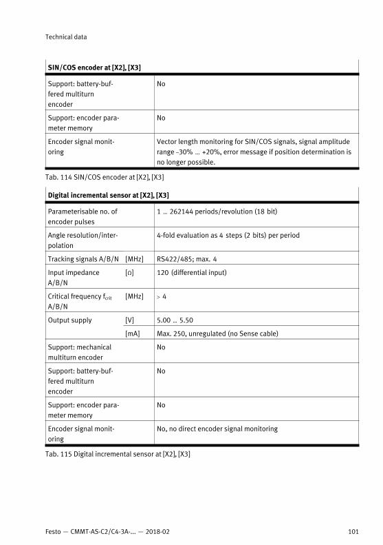
SIN/COS encoder at [X2], [X3]
Support: battery-buf-fered multiturnencoder
No
Support: encoder para-meter memory
No
Encoder signal monit-oring
Vector length monitoring for SIN/COS signals, signal amplituderange –30% ... +20%, error message if position determination isno longer possible.
Tab. 114 SIN/COS encoder at [X2], [X3]
Digital incremental sensor at [X2], [X3]
Parameterisable no. ofencoder pulses
1 … 262144 periods/revolution (18 bit)
Angle resolution/inter-polation
4-fold evaluation as 4 steps (2 bits) per period
Tracking signals A/B/N [MHz] RS422/485; max. 4
Input impedanceA/B/N
[Ω] 120 (differential input)
Critical frequency fcrit
A/B/N[MHz] > 4
[V] 5.00 … 5.50Output supply
[mA] Max. 250, unregulated (no Sense cable)
Support: mechanicalmultiturn encoder
No
Support: battery-buf-fered multiturnencoder
No
Support: encoder para-meter memory
No
Encoder signal monit-oring
No, no direct encoder signal monitoring
Tab. 115 Digital incremental sensor at [X2], [X3]
Technical data
101Festo — CMMT-AS-C2/C4-3A-... — 2018-02
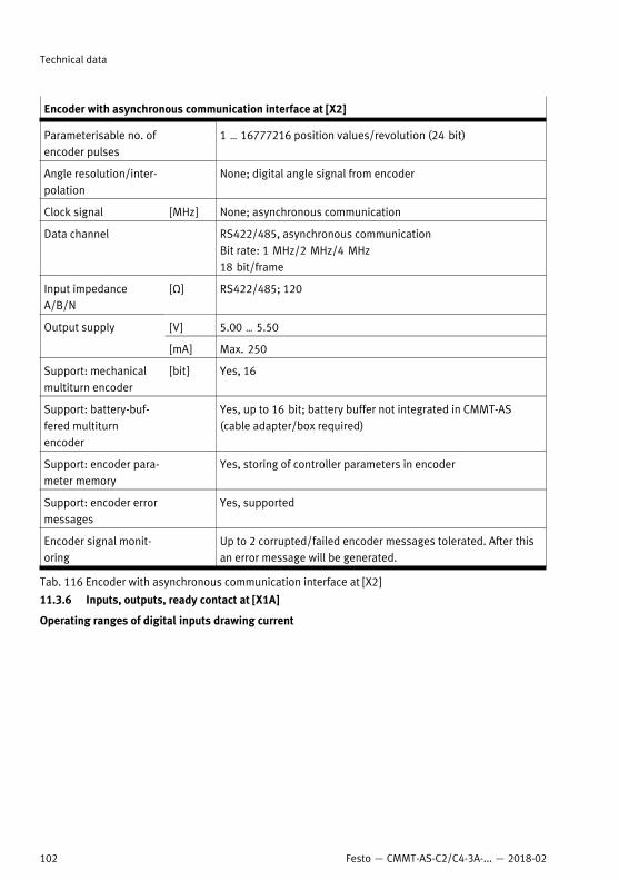
Encoder with asynchronous communication interface at [X2]
Parameterisable no. ofencoder pulses
1 … 16777216 position values/revolution (24 bit)
Angle resolution/inter-polation
None; digital angle signal from encoder
Clock signal [MHz] None; asynchronous communication
Data channel RS422/485, asynchronous communicationBit rate: 1 MHz/2 MHz/4 MHz18 bit/frame
Input impedanceA/B/N
[Ω] RS422/485; 120
[V] 5.00 … 5.50Output supply
[mA] Max. 250
Support: mechanicalmultiturn encoder
[bit] Yes, 16
Support: battery-buf-fered multiturnencoder
Yes, up to 16 bit; battery buffer not integrated in CMMT-AS(cable adapter/box required)
Support: encoder para-meter memory
Yes, storing of controller parameters in encoder
Support: encoder errormessages
Yes, supported
Encoder signal monit-oring
Up to 2 corrupted/failed encoder messages tolerated. After thisan error message will be generated.
Tab. 116 Encoder with asynchronous communication interface at [X2]
11.3.6 Inputs, outputs, ready contact at [X1A]
Operating ranges of digital inputs drawing current
Technical data
102 Festo — CMMT-AS-C2/C4-3A-... — 2018-02
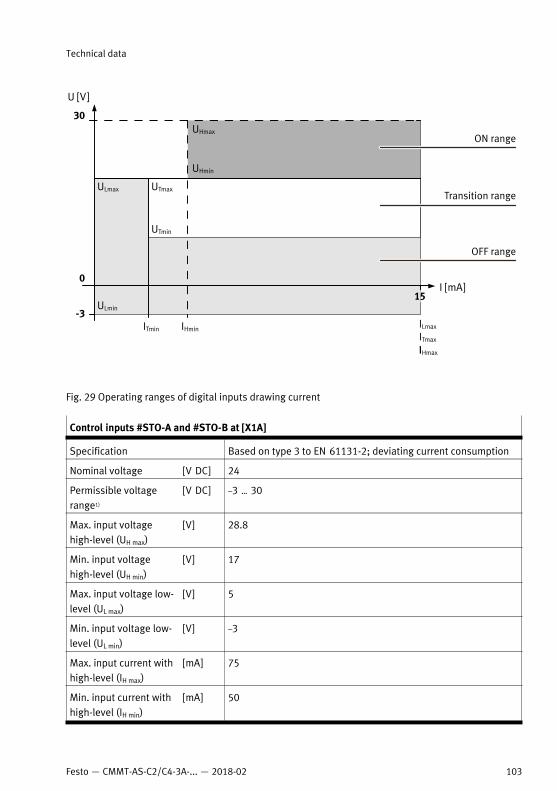
Fig. 29 Operating ranges of digital inputs drawing current
Control inputs #STO-A and #STO-B at [X1A]
Specification Based on type 3 to EN 61131-2; deviating current consumption
Nominal voltage [V DC] 24
Permissible voltagerange1)
[V DC] –3 … 30
Max. input voltagehigh-level (UH max)
[V] 28.8
Min. input voltagehigh-level (UH min)
[V] 17
Max. input voltage low-level (UL max)
[V] 5
Min. input voltage low-level (UL min)
[V] –3
Max. input current withhigh-level (IH max)
[mA] 75
Min. input current withhigh-level (IH min)
[mA] 50
Technical data
103Festo — CMMT-AS-C2/C4-3A-... — 2018-02
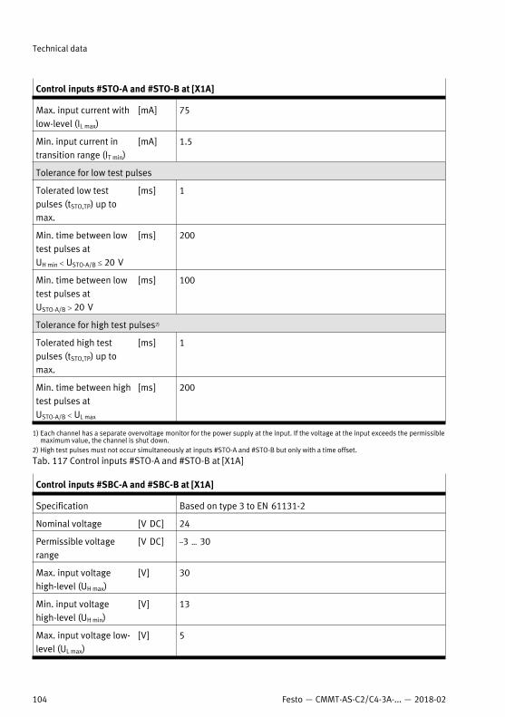
Control inputs #STO-A and #STO-B at [X1A]
Max. input current withlow-level (IL max)
[mA] 75
Min. input current intransition range (IT min)
[mA] 1.5
Tolerance for low test pulses
Tolerated low testpulses (tSTO,TP) up tomax.
[ms] 1
Min. time between lowtest pulses atUH min < USTO-A/B £ 20 V
[ms] 200
Min. time between lowtest pulses atUSTO-A/B > 20 V
[ms] 100
Tolerance for high test pulses2)
Tolerated high testpulses (tSTO,TP) up tomax.
[ms] 1
Min. time between hightest pulses atUSTO-A/B < UL max
[ms] 200
1) Each channel has a separate overvoltage monitor for the power supply at the input. If the voltage at the input exceeds the permissiblemaximum value, the channel is shut down.
2) High test pulses must not occur simultaneously at inputs #STO-A and #STO-B but only with a time offset.
Tab. 117 Control inputs #STO-A and #STO-B at [X1A]
Control inputs #SBC-A and #SBC-B at [X1A]
Specification Based on type 3 to EN 61131-2
Nominal voltage [V DC] 24
Permissible voltagerange
[V DC] –3 … 30
Max. input voltagehigh-level (UH max)
[V] 30
Min. input voltagehigh-level (UH min)
[V] 13
Max. input voltage low-level (UL max)
[V] 5
Technical data
104 Festo — CMMT-AS-C2/C4-3A-... — 2018-02
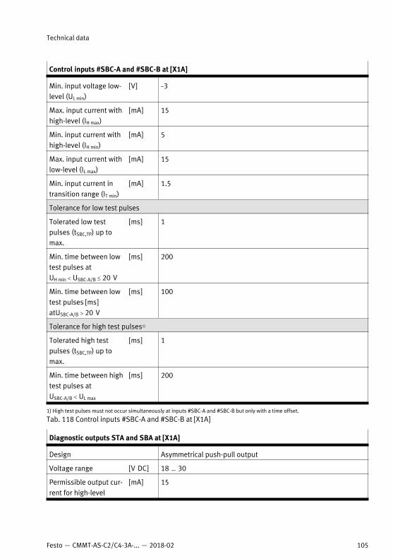
Control inputs #SBC-A and #SBC-B at [X1A]
Min. input voltage low-level (UL min)
[V] –3
Max. input current withhigh-level (IH max)
[mA] 15
Min. input current withhigh-level (IH min)
[mA] 5
Max. input current withlow-level (IL max)
[mA] 15
Min. input current intransition range (IT min)
[mA] 1.5
Tolerance for low test pulses
Tolerated low testpulses (tSBC,TP) up tomax.
[ms] 1
Min. time between lowtest pulses atUH min < USBC-A/B £ 20 V
[ms] 200
Min. time between lowtest pulses [ms]atUSBC-A/B > 20 V
[ms] 100
Tolerance for high test pulses1)
Tolerated high testpulses (tSBC,TP) up tomax.
[ms] 1
Min. time between hightest pulses atUSBC-A/B < UL max
[ms] 200
1) High test pulses must not occur simultaneously at inputs #SBC-A and #SBC-B but only with a time offset.
Tab. 118 Control inputs #SBC-A and #SBC-B at [X1A]
Diagnostic outputs STA and SBA at [X1A]
Design Asymmetrical push-pull output
Voltage range [V DC] 18 … 30
Permissible output cur-rent for high-level
[mA] 15
Technical data
105Festo — CMMT-AS-C2/C4-3A-... — 2018-02
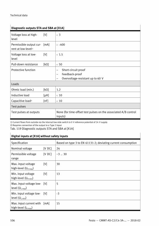
Diagnostic outputs STA and SBA at [X1A]
Voltage loss at high-level
[V] < 3
Permissible output cur-rent at low-level1)
[mA] < –400
Voltage loss at low-level
[V] < 1.5
Pull-down resistance [kΩ] < 50
Protective function – Short-circuit proof– Feedback-proof– Overvoltage-resistant up to 60 V
Loads
Ohmic load (min.) [kΩ] 1.2
Inductive load [µH] < 10
Capacitive load2) [nF] < 10
Test pulses
Test pulses at outputs None (for time-offset test pulses on the associated A/B controlinputs)
1) Current flows from outside via the internal low-side switch to 0 V reference potential of 24 V supply2) Requires connection of the output to a Type 3 input
Tab. 119 Diagnostic outputs STA and SBA at [X1A]
Digital inputs at [X1A] without safety inputs
Specification Based on type 3 to EN 61131-2; deviating current consumption
Nominal voltage [V DC] 24
Permissible voltagerange
[V DC] −3 … 30
Max. input voltagehigh-level (UH max)
[V] 30
Min. input voltagehigh-level (UH min)
[V] 13
Max. input voltage low-level (UL max)
[V] 5
Min. input voltage low-level (UL min)
[V] –3
Max. input current withhigh-level (IH max)
[mA] 15
Technical data
106 Festo — CMMT-AS-C2/C4-3A-... — 2018-02
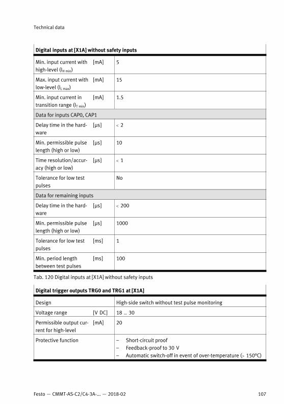
Digital inputs at [X1A] without safety inputs
Min. input current withhigh-level (IH min)
[mA] 5
Max. input current withlow-level (IL max)
[mA] 15
Min. input current intransition range (IT min)
[mA] 1.5
Data for inputs CAP0, CAP1
Delay time in the hard-ware
[µs] < 2
Min. permissible pulselength (high or low)
[µs] 10
Time resolution/accur-acy (high or low)
[µs] < 1
Tolerance for low testpulses
No
Data for remaining inputs
Delay time in the hard-ware
[µs] < 200
Min. permissible pulselength (high or low)
[µs] 1000
Tolerance for low testpulses
[ms] 1
Min. period lengthbetween test pulses
[ms] 100
Tab. 120 Digital inputs at [X1A] without safety inputs
Digital trigger outputs TRG0 and TRG1 at [X1A]
Design High-side switch without test pulse monitoring
Voltage range [V DC] 18 … 30
Permissible output cur-rent for high-level
[mA] 20
Protective function – Short-circuit proof– Feedback-proof to 30 V– Automatic switch-off in event of over-temperature (> 150°C)
Technical data
107Festo — CMMT-AS-C2/C4-3A-... — 2018-02
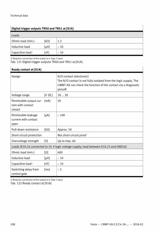
Digital trigger outputs TRG0 and TRG1 at [X1A]
Loads
Ohmic load (min.) [kΩ] 1.2
Inductive load [µH] < 10
Capacitive load1) [nF] < 10
1) Requires connection of the output to a Type 3 input
Tab. 121 Digital trigger outputs TRG0 and TRG1 at [X1A]
Ready contact at [X1A]
Design N/O contact (electronic)The N/O contact is not fully isolated from the logic supply. TheCMMT-AS can check the function of the contact via a diagnosticpickoff.
Voltage range [V DC] 18 … 30
Permissible output cur-rent with contactclosed
[mA] 50
Permissible leakagecurrent with contactopen
[µA] < 100
Pull-down resistance [kΩ] Approx. 50
Short-circuit protection Not short-circuit proof
Overvoltage strength [V] Up to max. 60
Loads (X1A.24 connected to 24 V logic voltage supply; load between X1A.23 and GND24)
Ohmic load (min.) [Ω] 600
Inductive load [µH] < 10
Capacitive load1) [nF] < 10
Switching delay fromcontrol gate
[ms] < 5
1) Requires connection of the output to a Type 3 input
Tab. 122 Ready contact at [X1A]
Technical data
108 Festo — CMMT-AS-C2/C4-3A-... — 2018-02
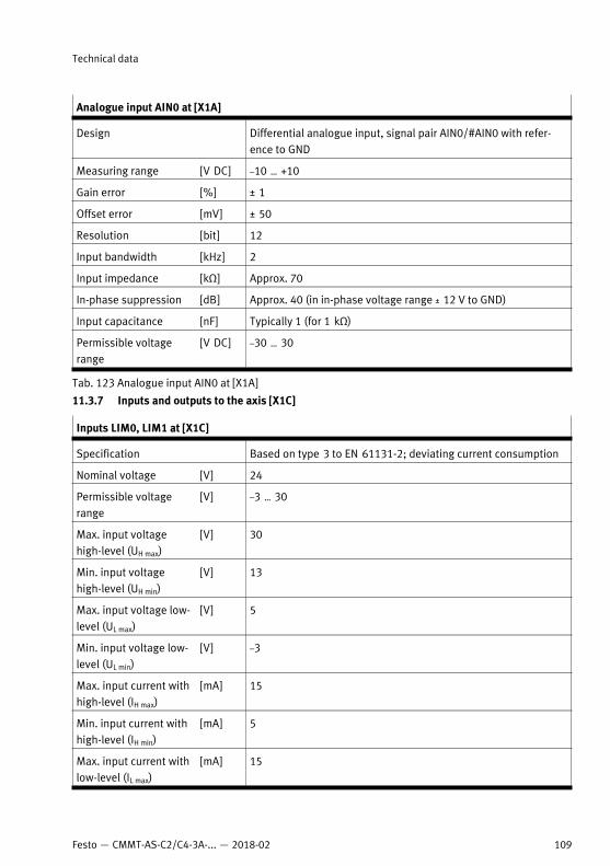
Analogue input AIN0 at [X1A]
Design Differential analogue input, signal pair AIN0/#AIN0 with refer-ence to GND
Measuring range [V DC] –10 … +10
Gain error [%] ± 1
Offset error [mV] ± 50
Resolution [bit] 12
Input bandwidth [kHz] 2
Input impedance [kΩ] Approx. 70
In-phase suppression [dB] Approx. 40 (in in-phase voltage range ± 12 V to GND)
Input capacitance [nF] Typically 1 (for 1 kΩ)
Permissible voltagerange
[V DC] –30 … 30
Tab. 123 Analogue input AIN0 at [X1A]
11.3.7 Inputs and outputs to the axis [X1C]
Inputs LIM0, LIM1 at [X1C]
Specification Based on type 3 to EN 61131-2; deviating current consumption
Nominal voltage [V] 24
Permissible voltagerange
[V] –3 … 30
Max. input voltagehigh-level (UH max)
[V] 30
Min. input voltagehigh-level (UH min)
[V] 13
Max. input voltage low-level (UL max)
[V] 5
Min. input voltage low-level (UL min)
[V] –3
Max. input current withhigh-level (IH max)
[mA] 15
Min. input current withhigh-level (IH min)
[mA] 5
Max. input current withlow-level (IL max)
[mA] 15
Technical data
109Festo — CMMT-AS-C2/C4-3A-... — 2018-02
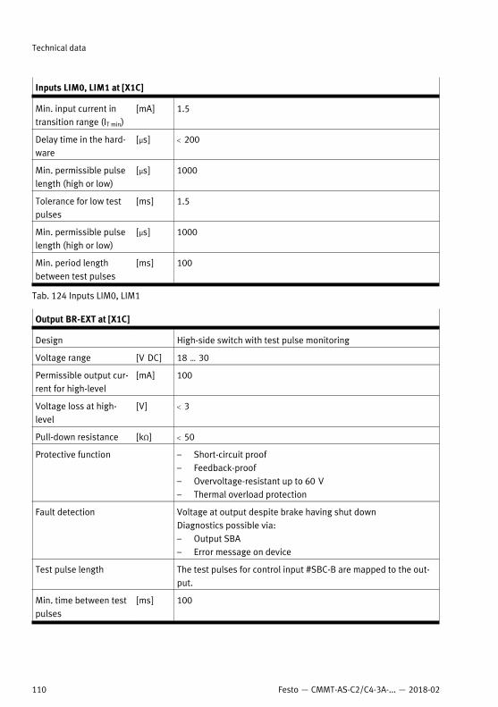
Inputs LIM0, LIM1 at [X1C]
Min. input current intransition range (IT min)
[mA] 1.5
Delay time in the hard-ware
[µs] < 200
Min. permissible pulselength (high or low)
[µs] 1000
Tolerance for low testpulses
[ms] 1.5
Min. permissible pulselength (high or low)
[µs] 1000
Min. period lengthbetween test pulses
[ms] 100
Tab. 124 Inputs LIM0, LIM1
Output BR-EXT at [X1C]
Design High-side switch with test pulse monitoring
Voltage range [V DC] 18 … 30
Permissible output cur-rent for high-level
[mA] 100
Voltage loss at high-level
[V] < 3
Pull-down resistance [kΩ] < 50
Protective function – Short-circuit proof– Feedback-proof– Overvoltage-resistant up to 60 V– Thermal overload protection
Fault detection Voltage at output despite brake having shut downDiagnostics possible via:– Output SBA– Error message on device
Test pulse length The test pulses for control input #SBC-B are mapped to the out-put.
Min. time between testpulses
[ms] 100
Technical data
110 Festo — CMMT-AS-C2/C4-3A-... — 2018-02
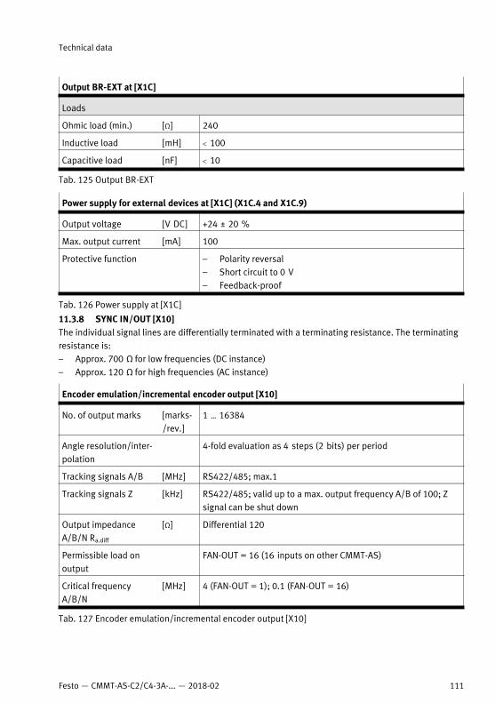
Output BR-EXT at [X1C]
Loads
Ohmic load (min.) [Ω] 240
Inductive load [mH] < 100
Capacitive load [nF] < 10
Tab. 125 Output BR-EXT
Power supply for external devices at [X1C] (X1C.4 and X1C.9)
Output voltage [V DC] +24 ± 20 %
Max. output current [mA] 100
Protective function – Polarity reversal– Short circuit to 0 V– Feedback-proof
Tab. 126 Power supply at [X1C]
11.3.8 SYNC IN/OUT [X10]The individual signal lines are differentially terminated with a terminating resistance. The terminatingresistance is:– Approx. 700 Ω for low frequencies (DC instance)– Approx. 120 Ω for high frequencies (AC instance)
Encoder emulation/incremental encoder output [X10]
No. of output marks [marks-/rev.]
1 … 16384
Angle resolution/inter-polation
4-fold evaluation as 4 steps (2 bits) per period
Tracking signals A/B [MHz] RS422/485; max.1
Tracking signals Z [kHz] RS422/485; valid up to a max. output frequency A/B of 100; Zsignal can be shut down
Output impedanceA/B/N Ra.diff
[Ω] Differential 120
Permissible load onoutput
FAN-OUT = 16 (16 inputs on other CMMT-AS)
Critical frequencyA/B/N
[MHz] 4 (FAN-OUT = 1); 0.1 (FAN-OUT = 16)
Tab. 127 Encoder emulation/incremental encoder output [X10]
Technical data
111Festo — CMMT-AS-C2/C4-3A-... — 2018-02
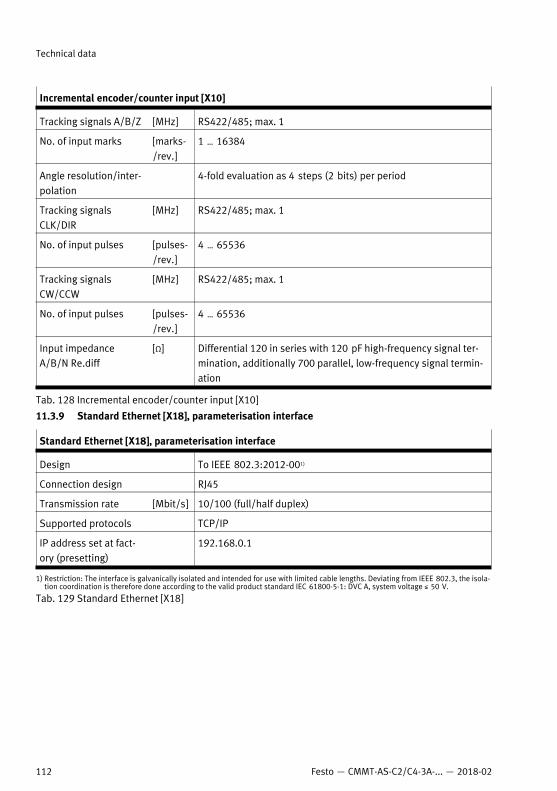
Incremental encoder/counter input [X10]
Tracking signals A/B/Z [MHz] RS422/485; max. 1
No. of input marks [marks-/rev.]
1 … 16384
Angle resolution/inter-polation
4-fold evaluation as 4 steps (2 bits) per period
Tracking signalsCLK/DIR
[MHz] RS422/485; max. 1
No. of input pulses [pulses-/rev.]
4 … 65536
Tracking signalsCW/CCW
[MHz] RS422/485; max. 1
No. of input pulses [pulses-/rev.]
4 … 65536
Input impedanceA/B/N Re.diff
[Ω] Differential 120 in series with 120 pF high-frequency signal ter-mination, additionally 700 parallel, low-frequency signal termin-ation
Tab. 128 Incremental encoder/counter input [X10]
11.3.9 Standard Ethernet [X18], parameterisation interface
Standard Ethernet [X18], parameterisation interface
Design To IEEE 802.3:2012-001)
Connection design RJ45
Transmission rate [Mbit/s] 10/100 (full/half duplex)
Supported protocols TCP/IP
IP address set at fact-ory (presetting)
192.168.0.1
1) Restriction: The interface is galvanically isolated and intended for use with limited cable lengths. Deviating from IEEE 802.3, the isola-tion coordination is therefore done according to the valid product standard IEC 61800-5-1: DVC A, system voltage ≤ 50 V.
Tab. 129 Standard Ethernet [X18]
Technical data
112 Festo — CMMT-AS-C2/C4-3A-... — 2018-02
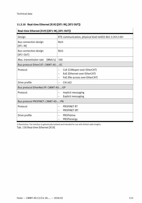
11.3.10 Real-time Ethernet [X19] ([XF1 IN], [XF2 OUT])
Real-time Ethernet [X19] ([XF1 IN], [XF1 OUT])
Design RTE communication, physical level toIEEE 802.3:2012-001)
Bus connection design[XF1 IN]
RJ45
Bus connection design[XF2 OUT]
RJ45
Max. transmission rate [Mbit/s] 100
Bus protocol EtherCAT: CMMT-AS-...-EC
Protocol – CoE (CANopen over EtherCAT)– EoE (Ethernet over EtherCAT)– FoE (file access over EtherCAT)
Drive profile – CIA 402
Bus protocol EtherNet/IP: CMMT-AS-...-EP
Protocol – Implicit messaging– Explicit messaging
Bus protocol PROFINET: CMMT-AS-...-PN
Protocol – PROFINET RT– PROFINET IRT
Drive profile – PROFIdrive– PROFIenergy
1) Restriction: The interface is galvanically isolated and intended for use with limited cable lengths.
Tab. 130 Real-time Ethernet [X19]
Technical data
113Festo — CMMT-AS-C2/C4-3A-... — 2018-02

Reproduction, distribution or sale of this document or communic-ation of its contents to others without express authorization isprohibited. Offenders will be liable for damages. All rightsreserved in the event that a patent, utility model or design patentis registered.
Copyright:Festo AG & Co. KG
73734 EsslingenRuiter Straße 82
Germany
+49 711 347-0
+49 711 347-2144Fax:
www.festo.comInternet:
Phone:
e-mail: