Embed Size (px)
Citation preview

SERVICING & STORMWATER MANAGEMENT REPORT35-37 WILLIAM STREET RE-DEVELOPMENT
Project No.: CP-19-0588
City File No.: D07-12-19-XXXX
Prepared for:
Domenic Santaguida35 William StreetOttawa, ON, K1N6Z9
Prepared by:
McIntosh Perry Consulting Engineers Ltd.115 Walgreen RoadCarp, ON K0A 1L0
December 18, 2019

35-37 William Street Re-DevelopmentServicing and Stormwater Management Report CP-19-0588
i
TABLE OF CONTENTS
1.0 PROJECT DESCRIPTION ........................................................................................................................... 1
1.1 Purpose ............................................................................................................................................................ 1
1.2 Site Description ................................................................................................................................................. 1
2.0 BACKGROUND STUDIES .......................................................................................................................... 2
3.0 PRE-CONSULTATION SUMMARY ............................................................................................................ 2
4.0 EXISTING SERVICES ................................................................................................................................. 3
4.1 Existing Sanitary ............................................................................................................................................... 3
4.2 Existing Storm ................................................................................................................................................... 3
4.3 Existing Water .................................................................................................................................................. 3
4.4 Site Utilities ...................................................................................................................................................... 3
5.0 SERVICING PLAN ..................................................................................................................................... 4
5.1 Proposed Servicing Overview ............................................................................................................................ 4
5.2 Proposed Water Design .................................................................................................................................... 4
5.3 Proposed Sanitary Design ................................................................................................................................. 6
5.4 Proposed Storm Design (Conveyance and Management)................................................................................... 6
6.0 PROPOSED STORMWATER MANAGEMENT ............................................................................................ 7
6.1 Design Criteria and Methodology ...................................................................................................................... 7
6.2 Runoff Calculations ........................................................................................................................................... 7
6.2.1 Pre-Development Drainage ....................................................................................................................... 8
6.2.2 Post-Development Drainage ..................................................................................................................... 8
6.3 Quantity Control ............................................................................................................................................... 9
6.4 Quality Control ................................................................................................................................................10
7.0 EROSION AND SEDIMENT CONTROL ..................................................................................................... 10
7.1 Temporary Measures .......................................................................................................................................10
8.0 SUMMARY ............................................................................................................................................ 11
9.0 RECOMMENDATIONS ........................................................................................................................... 13
10.0 STATEMENT OF LIMITATIONS ............................................................................................................... 14

35-37 William Street Re-DevelopmentServicing and Stormwater Management Report CP-19-0588
ii
LIST OF TABLES
Table 1: Water Demands .................................................................................................................................................. 4
Table 2: Water Pressure at Junctions per Scenario ........................................................................................................... 5
Table 3: Fire Protection Confirmation............................................................................................................................... 5
Table 4: Pre-Development Runoff Summary ..................................................................................................................... 8
Table 5: Post-Development Runoff Summary ................................................................................................................... 8
Table 6: Allowable Release Rate ....................................................................................................................................... 9
Table 7: Post-Development Stormwater Management Summary ..................................................................................... 9
Table 8: Roof Drain Summary ..........................................................................................................................................10
APPENDICES
APPENDIX A: Key Plan
APPENDIX B: Background Documents
APPENDIX C: Watermain Calculations
APPENDIX D: Sanitary Calculations
APPENDIX E: Pre-Development Drainage Plan
APPENDIX F: Post-Development Drainage Plan
APPENDIX G: Stormwater Management Calculations
APPENDIX H: City of Ottawa Development Servicing Study Checklist

35-37 William Street Re-DevelopmentServicing and Stormwater Management Report CP-19-0588
1
1.0 PROJECT DESCRIPTION
1.1 Purpose
McIntosh Perry (MP) has been retained by Domenic Santaguida to prepare this Servicing and StormwaterManagement Report in support of the Site Plan Control process for the proposed 4-storey mixed-use buildinglocated at 35-37 William Street within the City of Ottawa (City File No. D07-12-19-XXXX).
The main purpose of this report is to present a servicing design for the development in accordance with therecommendations and guidelines provided by the City of Ottawa (City), the Rideau Valley ConservationAuthority (RVCA), and the Ministry of the Environment, Conservation and Parks (MECP). This report will addressthe water, sanitary and storm sewer servicing for the development, ensuring that existing and available serviceswill adequately service the proposed development.
This report should be read in conjunction with the following drawings:· CP-19-0588, C101 – Removals, Site Servicing, Lot Grading and Drainage Plan
1.2 Site Description
The property is located at 35-37 William Street. It is described as Lot 11, Registered Plan 42482, Ward 12 –Rideau-Vanier, City of Ottawa, Ontario. The land in question covers approximately 0.05 ha and is located eastof William Street, just south of the intersection of York Street and William Street. See Appendix ‘A’ for Key Plan.
The site was developed with a restaurant and other small buildings in the rear however, the site currentlyconsists of the burned remains of those buildings due to a fire.
The proposed development consists of a four-storey mixed-use commercial and residential building with abasement level. The building will consist of 16 housing units and a restaurant. The foundation footprint isapproximately 471 m². The basement and the first floor will hold the restaurant while the second throughfourth floors will have residential units. The residential units are all 1-bedroom units. There will be access tothe building from entrances off of William Street and York Street.

35-37 William Street Re-DevelopmentServicing and Stormwater Management Report CP-19-0588
2
2.0 BACKGROUND STUDIESBackground studies that have been completed for the site include review of the City of Ottawa as-builtdrawings, and a topographical survey of the site.
As-built drawings of the existing services within the vicinity of the site were obtained from the City of OttawaInformation Center and were reviewed in order to determine proper servicing and stormwater managementschemes for the site. A copy of the drawings can be found in Appendix ‘B’.
A topographic survey of the site was completed by Annis, O’Sullivan, Vollebekk LTD. (Job No. 191004) and canbe found in Appendix ‘B’.
The following reports have been reviewed and are available under separate cover:
· Geotechnical Investigation completed by Paterson Group, dated October 7, 2019· Phase I ESA completed by Paterson Group, dated November 29, 2019· Phase II ESA completed by Paterson Group, dated December 03, 2019
3.0 PRE-CONSULTATION SUMMARYCity of Ottawa Staff have been pre-consulted regarding the proposed development in person on June 5, 2019.Specific design parameters to be incorporated within this design include the following:
· Pre-development time of concentration (TC) of 20 minutes or calculated but not less than 10 minutesand post-development flow shall be calculated using a time of concentration of 10 minutes.
· Control 5 through 100-year post-development flows to the 5-year pre-development flows,respectively, with a combined C value to a maximum of 0.50.
· Services shall be extended from William Street· Through correspondence with RVCA, it was noted the site has no quality control requirements.
Correspondence can be found in Appendix ‘B’.

35-37 William Street Re-DevelopmentServicing and Stormwater Management Report CP-19-0588
3
4.0 EXISTING SERVICESThe following subsections describe the existing services within the William Street right of way.
4.1 Existing Sanitary
The is an existing 250 mm diameter PVC Sanitary Sewer located within William Street. The sewer drains to the OttawaOutfall Trunk and then on to the Interceptor Sewer discharging at the Robert O. Pickard Environmental Centre(ROPEC). As-built information provided by the City of Ottawa indicates there is an existing sanitary service extendingfrom the 250 mm sewer which services the existing development on 35 William Street.
4.2 Existing Storm
There is an existing 375 mm diameter Storm Sewer within William Street. Catch basins are present near theexisting site entrance as well as across the road. The catch basins are connected to the storm main withinWilliam Street. The storm sewer drains to the West Kind Edward Storm Trunk Sewer and outlets to the OttawaRiver. As-built information provided by the City of Ottawa indicates there is an existing storm service extendingfrom the 375 mm sewer which services the existing development on 35 William Street.
4.3 Existing Water
There is an existing 300 mm diameter Watermain within William Street. As-Built information provided by theCity of Ottawa indicates a 100 mm diameter water service extends from the 300 mm watermain to service theexisting development on 35 William Street.
4.4 Site Utilities
As-built information provided by the City of Ottawa indicates a 50 mm diameter Gas main and a 680 mmdiameter hydro duct within the eastern sidewalk of William Street. The contractor is responsible for confirmingthe location of all Utilities.

35-37 William Street Re-DevelopmentServicing and Stormwater Management Report CP-19-0588
4
5.0 SERVICING PLAN
5.1 Proposed Servicing Overview
The overall servicing will be provided via service connections to the mains within William Street. The waterservice will be extended from the 300 mm diameter watermain. Similarly, the storm and sanitary services willbe connected to the 375 mm diameter and 250 mm diameter mains, respectively. Details pertaining to the finalproposed servicing locations have been reviewed and are shown on the proposed Site Servicing Plan.
5.2 Proposed Water Design
A new 100mm diameter PVC watermain is proposed to service the site complete with a water valve located atthe property line and will be connected to the existing 300 mm diameter watermain within William Street. Thewatermain is designed to have a minimum of 2.4m cover.
The Fire Underwriters Survey 1999 (FUS) method was utilized to determine the required fire flow for the site.The ‘C’ factor (type of construction) for the FUS calculation was determined to be 1.0 (ordinary typeconstruction). The total floor area (‘A’ value) for the FUS calculation was determined to be 1,655.12 m2. Theresults of the calculations yielded a required fire flow of 13,000 L/min. A fire flow of 4,500 L/min was calculatedusing the Ontario Building Code (OBC) requirements. The detailed calculations for the FUS and OBC can befound in Appendix ‘C’.
The water demands for the proposed building have been calculated to adhere to the Ottawa Design Guidelines– Water Distribution manual and can be found in Appendix ‘C’. The results have been summarized below:
Table 1: Water Demands
Average Day Demand (L/s) 0.11
Maximum Daily Demand (L/s) 0.25
Peak Hourly Demand (L/s) 0.54
OBC Fire Flow Requirement (L/s) 75.00
FUS Fire Flow Requirement (L/s) 216.66
Max Day + Fire Flow (FUS) (L/s) 216.92
Boundary conditions have been provided by the City of Ottawa for the current conditions and are available inAppendix ‘C’. The subject site is located in pressure zone 1W. A water model was completed using Bentley’sWaterCAD based on the boundary conditions. The results determined that the proposed 100mm watermaincan adequately service the proposed development and provide sufficient fire flow since Hydrant H-1 producedavailable fire flows of 22,736 L/min. Refer to drawing for more details. The results are available in Appendix ‘C’of this report.

35-37 William Street Re-DevelopmentServicing and Stormwater Management Report CP-19-0588
5
Prior to connecting to the municipal water distribution system, it is essential to determine whether the systemhas adequate capacity and that the overall impact to the existing system is minimal. A WaterCAD model wasgenerated to determine the capacity, pressure and size of pipes required to service the proposed site. Three(3) different scenarios were analyzed within the model, namely average day, maximum day + fire flow and peakhourly demands.
When modelling the proposed water distribution system for 35-37 William Street, it was necessary todetermine which scenario produced a greater demand: the maximum day + fire flow or peak hourly. It wasconcluded that the maximum day + fire flow scenario would govern the design process, since it produced thehigher demand. A layout of the WaterCAD model has been attached in Appendix C.
The normal operating pressure range is anticipated to be 422 kPa to 529 kPa and will not be less than 275 kPa(40 psi) or exceed 689 kPa (100 psi). The proposed watermain will meet the minimum required 20 psi (140 kPa)at the ground level under maximum day demand and fire flow conditions.
Table 2: Water Pressure at Junctions per Scenario
Junction Average Day (psi) Peak Hourly (psi) Max. Day + Fire Flow (psi)
J-1 (BLDG) 76.78 66.13 61.16
To confirm the adequacy of fire flow to protect the proposed development, public and private on-site firehydrants within 150 m of the proposed building were analysed per City of Ottawa ISTB 2018-02 Appendix ITable 1. The results are demonstrated below.
Table 3: Fire Protection Confirmation
BuildingFire Flow Demand
(L/min.)
Fire Hydrant(s)within 75m
(5,700 L/min)
Fire Hydrant(s)within 150m(3,800 L/min)
Combined FireFlow (L/min.)
35-37 WilliamStreet
13,000 2 4 26,600

35-37 William Street Re-DevelopmentServicing and Stormwater Management Report CP-19-0588
6
5.3 Proposed Sanitary Design
A new 100 mm diameter gravity sanitary service will be connected to the existing 250 mm diameter sanitarysewer within William Street.
The subject site is a proposed four-storey mixed-use commercial and residential building. The total area of thebuilding is 471 m2. The peak design flows for the proposed building were calculated using criteria from the Cityof Ottawa – Sewer Design Guidelines, October 2012. The proposed site development area (0.05ha) willgenerate a flow of 0.44 L/s.
The proposed 100 mm diameter gravity sanitary service will be installed with a minimum full flow targetvelocity (cleansing velocity) of 0.6 m/s and a full flow velocity of not more than 3.0 m/s. Design parameters forthe site include an infiltration rate of 0.28 l/s/ha.
The proposed service for the site will be connected to existing 250 mm diameter sanitary sewer within WilliamStreet. It is anticipated that flow from the site has been previously accounted for within the downstreaminfrastructure as a sanitary service from the previous restaurant development would have connected to thissewer. Although the sanitary flow is likely slightly higher for the proposed development, it is anticipated thatthere will be no issues with capacity constraints for the existing 250 mm sanitary main within William Street asless than 1% of additional capacity would be required.
See Sanitary Flow Calculations and Sanitary Sewer Design Sheet in Appendix ‘D’ of this report for more details.
5.4 Proposed Storm Design (Conveyance and Management)
Stormwater runoff will be conveyed by way of roof drains which will discharge into the existing infrastructurewithin William Street. The roof will provide storage by the use of roof drains before leaving the site. Roof drainswill restrict the flow to conform to City requirements.
A new 150 mm diameter storm service will be connected to the existing 375 mm diameter storm main withinWilliam Street. The storm service is provided as an outlet for the foundation drain system. The restricted flowfrom the roof drains will be connected to an additional 150 mm diameter storm service which will also beconnected to the existing 375 mm diameter storm main within William Street.
From discussions with the City of Ottawa and the Rideau Valley Conservation Authority (RVCA), quality controlwill not be provided within the site. Correspondence with the RVCA is available in Appendix ‘B’. Further detailsand calculations pertaining to the quantity and quality of the stormwater management system are provided inSection 6.0.

35-37 William Street Re-DevelopmentServicing and Stormwater Management Report CP-19-0588
7
6.0 PROPOSED STORMWATER MANAGEMENT
6.1 Design Criteria and Methodology
Stormwater management for this site will be maintained through roof storage and positive drainage away fromthe proposed building. Stormwater runoff will be restricted on the proposed roof and directed to the proposedstorm service before reaching the existing storm main within William Street. Overland flow will be directedtowards the William Street and York Street right-of-way. Stormwater Best Management Practices (SWM BMP’s)will be implemented at the “Lot level”, “Conveyance” and “End of Pipe” locations. These concepts will beexplained further in Section 6.4. In summary, the following design criteria have been employed in developingthe stormwater management design for the site as directed by the RVCA and City:
Quality Control
· No quality control is required for the site as per the RVCA.
Quantity Control
· Post-development flow 5/100-year is be restricted to match the 5-year pre-development flow with amaximum C value of 0.50.
6.2 Runoff Calculations
Runoff calculations presented in this report are derived using the Rational Method, given as:
CIAQ 78.2= (L/s)
Where C = Runoff coefficient
I = Rainfall intensity in mm/hr (City of Ottawa IDF curves)
A = Drainage area in hectares
It is recognized that the rational method tends to overestimate runoff rates. As a by-product of using extremelyconservative prediction method, any facilities that are sized using these results are expected to function asintended in real world conditions.
The following coefficients were used to develop an average C for each area:
Roofs/Concrete/Asphalt 0.90
Gravel 0.60
Undeveloped and Grass 0.20
As per the City of Ottawa Sewer Design Guidelines, the 5-year balanced ‘C’ value must be increased by 25% fora 100-year storm event to a maximum of 1.0.

35-37 William Street Re-DevelopmentServicing and Stormwater Management Report CP-19-0588
8
As per correspondence with City of Ottawa Staff the time of concentration (Tc) used for pre-development flowsis to be calculated or 20 minutes and post-development flows shall be 10 minutes.
6.2.1 Pre-Development Drainage
The existing site drainage limits are demonstrated on the Pre-Development Drainage Area Plan. The existingsite has been demonstrated as drainage area A1. See drawing CP-19-0588 – PRE within Appendix ‘E’ of thisreport for more details. Existing conditions have the overland stormwater runoff flowing from high pointslocated within the property and draining to existing storm infrastructure to the west (William Street) and tothe east (existing parking lot for 87 George Street). A summary of the Pre-Development Runoff Calculationscan be found below.
Table 4: Pre-Development Runoff Summary
Area ID DrainageArea (ha)
BalancedRunoff
Coefficient (C)5-year
BalancedRunoff
Coefficient(C) 100-year
5-Year FlowRate (l/s)
100-Year FlowRate (l/s)
A1 0.048 0.63 0.71 8.69 16.80
Total 0.048 8.69 16.80(See Appendix ‘G’ for Calculations)
6.2.2 Post-Development Drainage
The proposed site drainage limits are demonstrated on the Post-Development Drainage Area Plan. See CP-19-0588 - POST in Appendix ‘F’ of this report for more details. A summary of the Post-Development RunoffCalculations can be found below.
Table 5: Post-Development Runoff Summary
Area ID DrainageArea (ha)
BalancedRunoff
Coefficient (C)5-year
BalancedRunoff
Coefficient (C)100-year
5-year FlowRate (L/s)
100-year FlowRate (L/s)
B1 0.006 0.90 1.00 1.56 2.96
B2 0.002 0.90 1.00 0.47 0.89
B3 0.033 0.90 1.00 8.63 16.43
B4 0.005 0.90 1.00 1.25 2.38
B5 0.002 0.90 1.00 0.56 1.06
Total 0.048 12.46 23.73(See Appendix ‘G’ for Calculations)

35-37 William Street Re-DevelopmentServicing and Stormwater Management Report CP-19-0588
9
Runoff from areas B1-B4 will be restricted through the use of roof drains. The roof restrictions will restrict the100-year runoff to the 5-year pre-development flow rate while accounting for the proposed unrestricted flowfrom drainage area B5. See Appendix ‘G’ for calculations. This restriction will be further detailed in Section 6.3.
6.3 Quantity Control
After discussing the stormwater management criteria for the site with City of Ottawa staff, the 5 and 100-yearpost-development runoff for this site has been restricted to match the 5 year flow rate with a maximum C valueof 0.5 (See Appendix ‘B’ for correspondence). These values create the following allowable release rates andstorage volumes for the development site.
Table 6: Allowable Release Rate
Area DrainageArea (ha)
Balanced RunoffCoefficient (C) 5-yr Tc (min) 5-Year Flow Rate (L/s)
A1 0.048 0.50 10 6.92(See Appendix ‘G’ for Calculations)
Reducing site flows will be achieved using roof drains and will create the need for roof storage. Runoff fromareas B1- B4 will be restricted as detailed below.
Table 7: Post-Development Stormwater Management Summary
Area ID Area(ha)
Restricted Flow(L/s)
Storage Required(m3)
Storage Provided(m3)
5-yr 100-yr 5-yr 100-yr 5-yr 100-yr
B1 0.006 0.30 0.54 0.91 1.77 1.12 2.02
B2 0.002 0.18 0.36 0.17 0.32 0.20 0.40
B3 0.033 1.08 1.80 6.19 12.27 7.45 12.41
B4 0.005 0.24 0.48 0.73 1.35 0.73 1.44
B5 0.002 0.56 1.06
Total 0.048 2.36 4.24 (See Appendix ‘G’ for Calculations)
Area B1 is the Lower Terrace on the West side of the building roof area (Level 2 Roof). Runoff from Area B1 willbe restricted by one roof drain restricting the flows to 0.30 L/s and 0.54 L/s for the 5-year and 100-year stormevents. Area B2 is the Western portion of the third level roof. Area B2 will be restricted by one roof drainrestricting the flows to 0.18 L/s and 0.36 L/s for the 5-year and 100-year storm events. Area B3 is the fourthlevel roof. Area B3 will be restricted by three roof drains restricting the flows to 1.08 L/s and 1.80 L/s for the 5-year and 100-year storm events. Area B4 is the southern portion of the second level roof. Area B4 will be

35-37 William Street Re-Development Servicing and Stormwater Management Report CP-19-0588
10
restricted by one roof drain restricting the flows to 0.24 L/s and 0.48 L/s for the 5-year and 100-year storm
events. Drainage areas for the roof are depicted on CP-19-0588 – POST plan available within Appendix ‘E’. The
table below details the required and provided rooftop storage volumes for the development.
Table 8: Roof Drain Summary
Area ID
Area (ha)
Number of roof Drains
Total Restricted Flow (L/s)
Storage Depth (m)
Storage Volume
Required (m3)
Storage Volume
Available (m3)
5-Yr 100-Yr 5-Yr 100-Yr 5-Yr 100-Yr 5-Yr 100-Yr
B1 0.006 1 0.30 0.54 0.025 0.045 0.91 1.77 1.12 2.02
B2 0.002 1 0.18 0.36 0.015 0.030 0.17 0.32 0.20 0.40
B3 0.033 3 1.08 1.80 0.035 0.050 6.19 12.27 7.45 12.41
B4 0.005 1 0.24 0.48 0.020 0.045 0.73 1.35 0.73 1.44
(See Appendix ‘G’ for Calculations)
In the event that there is a rainfall above the 100-year storm event, or a blockage within the storm sewer
system, an emergency roof scuppers have been provided so that the storm water runoff will not build up on
the roof.
6.4 Quality Control
The development of this lot will employ Best Management Practices (BMP’s) wherever possible. The intent of
implementing stormwater BMP’s is to ensure that water quality and quantity concerns are addressed at all
stages of development. Lot level BMP’s typically include temporary retention of the lot runoff, minimizing
ground slopes and maximizing landscaped areas. Some of these BMP’s cannot be provided for this site due to
site constraints and development requirements.
As per the discussions with the RVCA, there are no quality control requirements for the site. Please refer to
Appendix ‘B’ for correspondence with the RVCA. The combination of the above BMP’s and the proposed flow
control measures will aid in the protection of the natural environment.

35-37 William Street Re-Development Servicing and Stormwater Management Report CP-19-0588
11
7.0 EROSION AND SEDIMENT CONTROL
7.1 Temporary Measures
Before construction begins, temporary silt fence, straw bale or rock flow check dams will be installed at all
natural runoff outlets from the property. It is crucial that these controls be maintained throughout construction
and inspection of sediment and erosion control will be facilitated by the Contractor or Contract Administration
staff throughout the construction period.
Silt fences will be installed where shown on the final engineering plans, specifically along the downstream
property limits. The Contractor, at their discretion or at the instruction of the City, Conservation Authority or
the Contract Administrator shall increase the quantity of sediment and erosion controls on-site to ensure that
the site is operating as intended and no additional sediment finds its way off site. The rock flow, straw bale &
silt fence check dams and barriers shall be inspected weekly and after rainfall events. Care shall be taken to
properly remove sediment from the fences and check dams as required. Fibre roll barriers are to be installed
at all existing curb inlet catchbasins and filter fabric is to be placed under the grates of all existing catchbasins
and manholes along the frontage of the site and any new structures immediately upon installation. The
measures for the existing/proposed structures are to be removed only after all areas have been paved. Care
shall be taken at the removal stage to ensure that any silt that has accumulated is properly handled and
disposed of. Removal of silt fences without prior removal of the sediments shall not be permitted.
Although not anticipated, work through winter months shall be closely monitored for erosion along sloped
areas. Should erosion be noted, the Contractor shall be alerted and shall take all necessary steps to rectify the
situation. Should the Contractor’s efforts fail at remediating the eroded areas, the Contractor shall contact the
City and/or Conservation Authority to review the site conditions and determine the appropriate course of
action. As the ground begins to thaw, the Contractor shall place silt fencing at all required locations as soon as
ground conditions warrant. Please see the Removals, Site Servicing, Lot Grading and Drainage Plan for
additional details regarding the temporary measures to be installed and their appropriate OPSD references.

35-37 William Street Re-Development Servicing and Stormwater Management Report CP-19-0588
12
8.0 SUMMARY
• A new 471 m2 ground floor area four-story mixed-use commercial and residential building will be
constructed on the site located at 35-37 William Street.
• A new 150 mm diameter sanitary service will be installed and connected to the existing 250 mm
diameter sewer within William Street.
• A new 100 mm diameter water lateral will be extended from the existing 300 mm diameter main
within William Street.
• A new 150 mm storm service will be installed for the roof drainage system and connected to the
existing 375 mm diameter sewer within William Street.
• A new 150 mm storm service will be installed for the foundation drainage system and connected to
the existing 375 mm dimeter sewer within William Street.
• As discussed with City of Ottawa staff, the stormwater management design will ensure that the
post-development flow rates are restricted to the 5-year pre-development flow rates calculated
with a maximum C value of 0.5.
• Storage for the 5 and 100-year storm events will be provided on the proposed flat roof.

35-37 William Street Re-DevelopmentServicing and Stormwater Management Report CP-19-0588
13
9.0 RECOMMENDATIONSBased on the information presented in this report, we recommend that City of Ottawa approve this Servicingand Stormwater Management Report in support of the proposed development located at 35-37 William Street.
This report is respectfully being submitted for approval.
Regards,
McIntosh Perry Consulting Engineers Ltd.
Nicholas Vachon, EITEngineering Intern, Land DevelopmentMcIntosh Perry Consulting EngineersT: 613.875.1334E:[email protected]
Tyler Ferguson, P.Eng.Project Engineer, Land DevelopmentMcIntosh Perry Consulting EngineersT: 613.903.4426E: [email protected]
h:\01 project - proposals\2019 jobs\cp\0cp-projects\0cp-19-0588 domenic santaguida_vittoria trattoria_35 william st\03 - servicing\report\cp-19-0588_servicing report.docx

35-37 William Street Re-DevelopmentServicing and Stormwater Management Report CP-19-0588
14
10.0 STATEMENT OF LIMITATIONSThis report was produced for the exclusive use of Vittoria Trattoria. The purpose of the report is to assess theexisting stormwater management system and provide recommendations and designs for the post-constructionscenario that are in compliance with the guidelines and standards from the Ministry of the Environment,Conservation and Parks, City of Ottawa and local approval agencies. McIntosh Perry reviewed the siteinformation and background documents listed in Section 2.0 of this report. While the previous data wasreviewed by McIntosh Perry and site visits were performed, no field verification/measures of any informationwere conducted.
Any use of this review by a third party, or any reliance on decisions made based on it, without a reliance reportis the responsibility of such third parties. McIntosh Perry accepts no responsibility for damages, if any, sufferedby any third party as a result of decisions or actions made based on this review.
The findings, conclusions and/or recommendations of this report are only valid as of the date of this report.No assurance is made regarding any changes in conditions subsequent to this date. If additional information isdiscovered or becomes available at a future date, McIntosh Perry should be requested to re-evaluate theconclusions presented in this report, and provide amendments, if required.

APPENDIX AKEY PLAN

LAURIER AVENUE EAST
SUSSEX DRIVE
RIDEAU STREET
ELGIN STREET
MURRAY STREET
LAURIER AVENUE WEST
WELLINGTON STREET
VANIER PARKWAY
SOMERSET STREET WEST
KING EDWARD AVENUE
NICHOLAS STREET
QUEEN ELIZABETH DRIVEWAY
ALEXANDRA BRIDGE
MACDONALD CARTIER BRIDGE
AVENUE
Rideau River
LEGEND
35-37 WILLIAM STREETRE-DEVELOPMENT
SITE LOCATION
1FIGURE:
DOMENIC SANTAGUIDA
Dec., 17, 2019LCNV
TITLE:
CLIENT:
PROJECT:
H:\01
Proj
ect -
Prop
osals
\2019
Jobs
\CP\
0CP-
Proje
cts\0C
P-19
-0588
Dom
enic
Santa
guida
_Vitto
ria Tr
attori
a_35
Willia
m St\
13 - G
IS\mx
d\CP-
19-05
88_0
1_Sit
eLoc
ation
.mxd
REFERENCE
Site LocationLocal RoadMajor Road
WatercourseWaterbodyWooded Area
GIS data provided by the Ontario Ministry of Natural Resources and Forestry, 2019.
Site Location
PROJECT NO: DateGISChecked By
CP-19-0588
115 Walgreen Road, RR3, Carp, ON K0A1L0Tel: 613-836-2184 Fax: 613-836-3742
www.mcintoshperry.com
Metres
500 0 500250
Scale 1:15,000

APPENDIX BBACKGROUND DOCUMENTS


1
Nicholas Vachon
From: Eric Lalande <[email protected]>Sent: December 6, 2019 8:52 AMTo: Nicholas VachonSubject: RE: 35-37 William Street - RVCA Requirements
Hi Nicholas,
The RVCA has no requirements for quality control at this location based on the proposed site plan provided.Best Management practices are encouraged on site where possible to be integrated into the design.
Thank you,
Eric Lalande, MCIP, RPPPlanner, Rideau Valley Conservation Authority613-692-3571 x1137
From: Nicholas Vachon <[email protected]>Sent: Thursday, December 05, 2019 1:16 PMTo: Eric Lalande <[email protected]>Cc: Tyler Ferguson <[email protected]>Subject: 35-37 William Street - RVCA Requirements
Hi Eric,
We have a development moving forward at 35-37 William Street. They are proposing to add a 4-storey (plus basement)Mixed Use Commercial and Residential Building as per the attached Site Plan. We had a pre-consultation with the City.Can you confirm the quality control requirement for the site?
If you could please review and let me know, any questions feel free to contact me.
Regards,
Nicholas Vachon, EITEngineering Intern115 Walgreen Road, R.R. 3, Carp, ON K0A 1L0T. [email protected] | www.mcintoshperry.com
Confidentiality Notice – If this email wasn’t intended for you, please return or delete it. Click here to read all of the legal language around this concept.

1
Pre-application Consultation Meeting Minutes Address: 35 and 37 William Street and 54 York Street
Formal Pre-consultation File No.: PC2019-0129 Date: Wednesday June 5, 2019, 11:00am – 12:30pm Location: Room 4105, City Hall, 110 Laurier Ave W
City Contact: Ann O’Connor City of Ottawa Staff Present: Ann O’Connor – File Lead, Planner, Central Development Review Sally Coutts – Heritage Planner Christopher Moise – Urban Designer Shawn Wessel – Infrastructure Project Manager Wally Dubyk – Transportation Project Manager Mark Gordon – Planning Student Invitees Present: Robert (Bob) Tritt – Lowertown Community Association Representative Bill Holzman – Planner, Holzman Consultants Barry Padolsky – Architect, Barry Padolsky Associates Inc. Domenic Santaguido – Property Owner Introductions and Acknowledgements
Round table introductions
Acknowledgement that an NDA has been signed by the Lowertown Community Association Representative
Overview of Proposal (Domenic Santaguido, Bill Holzman, and Barry Padolsky)
The property at 35 and 37 William Street is currently occupied by a two-storey
restaurant, known as Vittoria Trattoria, which was recently damaged in a fire. The
extent of the façade and structural fire damage is still being researched.
The proposal is to replace the damaged structure with a three or four-storey
building. The third and fourth storey are to be set back from the front façade of
the building. The redevelopment also includes developing the rear (southern half)
of 62 York Street. This land has not yet been severed or acquired.
Domenic owns 35 William Street and rents 37 William Street (which is a part of
the existing restaurant).
A southern portion of 54 York Street is undeveloped and located between the
building at 54 York Street and the building at 35 and 37 William Street. This area
is known as “feathers lane”. Until recently, this area was used to manage the
waste for both properties and is currently filled with scaffolding (as a result of the
fire). As a part of this redevelopment, the applicant is also considering
cantilevering the upper storeys over feathers lane.

2
Preliminary Comments from the City
Planning Comments (Ann O’Connor)
Based on the current proposal, the following are required:
o Site Plan Control
- Please note that this would be a “New Mixed-Use Building” as there
is no Site Plan Agreement on title. An application is considered
‘new’ if site plan control approval has never been granted.
- Whether or not this application will be “Complex” (subject to public
consultation) or “Standard” will depend on the ultimate proposal.
- The policy requires that the following is subject to public
consultation (Complex): “New mixed-use buildings containing
fourteen or more units, five or more storeys or with a gross floor
area of 1,400 square metres or more”. Please note that when
calculating the GFA, include the basement area (see the definition
of GFA in the Zoning Bylaw).
o Committee of Adjustment Minor Variance application or a Minor Zoning
By-law Amendment application. Depending on the number and type of
variances requested, one approach may be more appropriate than the
other.
o Heritage application through the Heritage Act.
o Request to participate in the Urban Design Review Panel (UDRP) during
the other Planning Act applications.
Planning Services supports the redevelopment of the property post-fire. It is
important to the department that the proposal be sensitively designed to be
respectful of the existing heritage and built form context.
The property is designated “Central Area” in Schedule B of the Official Plan.
The properties are subject to the Central Area Secondary Plan
o Schedule B designates the properties “ByWard Market” character area
o Schedule B-2A designates the properties as being within the “ByWard
Market” area and subject to building heights outlined in Volume 2 –
Central Area Secondary Policy Plan
o Note that the ByWard Market is designated a Heritage Conservation
District. Alterations to properties within the area will be assessed on their
sensitivity to the heritage character of the property and the district as a
whole. And, in accordance with the Secondary Plan, Council shall ensure
that the scale of development is predominantly low profile, is of a human

3
scale, is compatible with the heritage character of the area, and protects
sunlight patterns and significant views.
The properties 35 and 37 William Street, 54 York Street, and 62 York Street are
all zoned MD2 S73 – Mixed Use Downtown Zone, Subzone 2, Schedule 73. It is
also within the Heritage Overlay (Section 60 of the Zoning By-law). There are
some known and some not-yet-known areas of non-compliance. Below is a list of
potential areas of non-compliance:
o Height (9.2m required and currently 13.5m proposed)
o Heritage Overlay provisions
o Maximum width of uses at ground floor (currently limited to 6m; there
appears to be an existing non-conforming situation)
o Amenity space for proposed dwelling units (currently none is illustrated on
the floor plans)
o Bicycle parking (Planning would prefer to see all required bike parking
provided)
o Visitor vehicular parking (some visitor parking may be required depending
on number of proposed dwelling units)
o Outdoor storage (none is permitted)
The properties are a part of the ByWard Market Public Realm Study. As a part of
this study, a pilot project is currently taking place whereby William Street
between George and York is closed to vehicles (pedestrian and cycling only).
This pilot project is stated to finish in October 2019. Jillian Savage is the project
lead for this study at the City of Ottawa.
The property is subject to the ByWard Market Precinct Strategy, as outlined in
DOUDS (Downtown Ottawa Urban Design Strategy).
The properties are located within a “Design Priority Area” as the property is
located in the Central Area. Despite the fact that the building is four storeys or
less, Planning Services encourages the applicant to go through the Urban
Design Review Panel (UDRP) process. The property location has heritage and
design significance and the proposal would benefit from this additional process.
Comments on the current proposal and approach:
o There are many unknowns that require further research and clarity before
proceeding with the current design. These unknowns include:
- The extent of the fire damage (to be confirmed through an ongoing
study)
- The existing ownership and potential land transfer of the property
illustrated as being used as a rear-yard access (municipally known
as 87 George St).

4
- The potential severance and land transfer to the east (as an
extension of this 87 George St parcel) to access the proposed rear-
yard patio for 35 and 37 William St.
- The potential severance and land transfer of the rear portion of 62
York.
- The potential establishment of an easement over a southern strip of
54 York in favour of 35 and 37 William Street (“feathers lane”).
o It would be valuable for the applicant’s team to model the surrounding
context to illustrate the proposal’s relationship to the existing built forms
and abutting context. The proposal can then be put into the model, and
the massing can be adjusted to respond to this context. This will be
particularly helpful in understanding: (1) how the height relates to 54 York;
and (2) how the wrap-around mass in the rear yard relates to 41, 41 ½ ,
and 43 William Street.
o Ensure the new design continues to respond to the William Street context.
Regardless of whether the residential component has access at the rear,
the building façade facing William should continue to be active and
engage with the public realm.
o Address waste management. The waste management situation in
“feathers lane” currently appears to serve both 54 York and 35 and 37
William Street. Consider how both properties/uses will be impacted by the
proposed new waste management strategy. Consider accessibility,
convenience, and the possible nuisance (smell) of waste storage and
removal.
o Address the pedestrian and cycling connections. Easily accessible and
secure bicycle parking is a priority.
o Address how to make the development accessible and sustainable.
Heritage Comments (Lesley Collins / Sally Coutts)
The property is designated under Part V of the Ontario Heritage Act and is located in the ByWard Market HCD.
An application under the Ontario Heritage Act will be required for the stabilization or reconstruction of the building, a Cultural Heritage Impact Statement is also required. The CHIS must be prepared by an independent heritage professional and not the architect for the project. Further details regarding the application requirement will be provided once the proposal is finalized (ie. Demolish and reconstruction or stabilize and construct etc)

5
Staff would like to see a 3D model of the proposed building, as well as a view analysis using the views in the attached document.
See attached map of requested views for heritage. Urban Design Comments (Christopher Moise)
Provide clarity as to whether the second storey will be occupied by a commercial use
Provide clarity on how feather lane and how waste management will be managed
There is some concern about the quality of the space (depth and access to light) used by the dwelling units.
Provide clarity on how the basement will be used without any windows
Explore the idea of doubling the height of the lobby
Model how the development will function, including access to light and glazing opportunities.
Infrastructure Comments (Shawn Wessel)
Infrastructure: o A 305 mm dia. PVC Watermain (c. 2001) is available on William St.
o A 250 mm dia. PVC Sanitary Sewer (c. 2000) on William St., which drains
to Otawa Outfall Trunk and on to the Interceptor Sewer discharging at ROPEC.
o A 375 dia. mm PVC Storm Sewer (c. 2000) on William St., which drains to the West King Edward Storm Trunk Sewer and Outlets to the Ottawa River.
o Please note: Applicant to contact Rideau Valley Conservation Authority (RVCA) for possible restrictions due to quality control. Provide correspondence in Report.
o The following apply to this site and any development within a separated sewer area:
Total (San & Stm) allowable release rate will be 5 year pre-development rate if:
Not within a partially separated sewer area

6
Sewer Pipe is newer than 1970 or within Vanier Area where no less than 450mm dia. - otherwise use 2 year pre-dev. Rate
Coefficient (C) of runoff will need to be determined as per existing
conditions but in no case more than 0.5
TC = 20 minutes or can be calculated
TC should be not be less than 10 minutes, since IDF curves become unrealistic at less than 10 min.
Any storm events greater than 5 year, up to 100 year, and including
100 year storm event must be detained on site.
Two separate sewer laterals (one for sanitary and other for storm) will be required. Please note:
Foundation drains are to be independently connected to sewermain (separated or combined) unless being pumped with appropriate back up power, sufficient sized pump and back flow prevention.
Roof drains are to be connected downstream of any incorporated ICD within the SWM system.
o Boundary Conditions will be provided at request of consultant after
providing Average Daily Demands, Peak Hour Demands & Max Day + Fire Flow Demands
Other: o Due to more sensitive use a Record of Site Condition (RSC) is
required. Ensure Phase I, and if applicable, Phase II ESA’s speak to required RSC.
o Buildings and Facilities renewal project planned for By Ward Markey Square for this season.
o Water Supply Redundancy – Fire Flow: Applicant to ensure that a second service with an inline valve
chamber be provided where the average daily demand exceeds 50 m³ / day (0.5787 l/s per day)
o Where underground storage (UG) and surface ponding are being
considered: Show all ponding for 5 and 100 year events
Note - There must be at least 15cm of vertical clearance between
the spill elevation and the ground elevation at the building envelope

7
that is in proximity of the flow route or ponding area. The exception in this case would be at reverse sloped loading dock locations. At these locations, a minimum of 15cm of vertical clearance must be provided below loading dock openings. Ensure to provide discussion in report and ensure grading plan matches if applicable.
Provide information on type of underground storage system including product name and model, number of chambers, chamber configuration, confirm invert of chamber system, top of chamber system, required cover over system and details, interior bottom slope (for self-cleansing), chart of storage values, length, width and height, capacity, entry ports (maintenance) etc.
Provide a cross section of underground chamber system showing invert and obvert/top, major and minor HWLs, top of ground, system volume provided during major and minor events. UG storage to provide actual 2 and 100 year event storage requirements.
In regards to all proposed UG storage, ground water levels (and in particular HGW levels) will need to be reviewed to ensure that the proposed system does not become surcharged and thereby ineffective.
o Modeling can be provided to ensure capacity for both storm and sanitary
sewers for the proposed development by City’s Water Distribution Dept. – Modeling Group, through PM and upon request.
o Provided Info: Please be advised that it is the responsibility of the applicant and
their representatives/consultants to verify information provided by the City of Ottawa.
Please contact City View and Release Info Centre at Ext. 44455
Environmental Source Information: o City of Ottawa - Historical Land Use Inventory (HLUI)
The HLUI database is currently undergoing an update. The updated HLUI will include additional sources beyond those included in the current database, making the inclusion of this record search even more important.
Although a municipal historic land use database is not specifically listed as required environmental record in O. Reg 153/04, Schedule D, Part II states the following:
The following are the specific objectives of a records review:

8
To obtain and review records that relate to the Phase I (One) property and to the current and past uses of and activities at or affecting the Phase I (One) property in order to determine if an area of potential environmental concern exists and to interpret any area of potential environmental concern.
To obtain and review records that relate to properties in the Phase I (One) study area other than the Phase I (One) property, in order to determine if an area of potential environmental concern exists and to interpret any area of potential environmental concern.
o It is therefore reasonable to request that the HLUI search be included in
the Phase I ESA to meet the above objectives. Please submit. o Existing buildings require a CCTV inspection and report to ensure existing
services to be re-used are in good working order and meet current minimum size requirements. Located services to be placed on site servicing plans.
CCTV Scan
Guideline.pdf
o There is a possibility that a large sanitary lateral existing under and servicing buildings from 54 York to 61 William Streets where sanitary and roof storm water flows are collected and likely discharged into City infrastructure on George St. This will need to be investigated to ensure that if such sanitary lateral exists, that this service is not severed and/or interrupted and is protected from damage etc.
o Due to this SPC application and the fact that storm water (particularly roof water) is not permitted to drain into the sanitary sewer lateral and into City Sanitary infrastructure, a new storm lateral is required.
o Furthermore, a Site servicing & SWM Report will be required to speak to how the roof tops, terraces and patio are drained and to specific details about site servicing.
Transportation Comments (Wally Dubyk)
The TIA Step 1 – Screening report is to be revised to reflect any changes to the proposal. Provided no additional triggers are met, no further TIA reports will be required.
In the submission, provide an explanation of how loading / drop-off for the restaurant use will be accommodated.
A construction Traffic Management Plan is to be provided for approval by the Senior Engineer, Traffic Management, Transportation Services Dept.

9
Bicycle parking spaces are required as per Section 111 of the Zoning By-law. Bicycle parking spaces should be located in safe, secure places near main entrances and preferably protected from the weather.
Further comments related to a Site Plan will be provided.
Preliminary Comments from Lowertown Community Association Representative (Bob Tritt)
Desire to conserve as much as possible.
Overall, the community sees it as a priority to see this property be re-built.
Happy to see residential incorporated into the proposal.
Consider how bicycle parking will be dealt with.
Consider how waste management will be dealt with. Next Steps
Finalize the ongoing study to determine the extent of the fire damage. This will be critical in determining the façade and structural impacts.
Research property ownership and legal agreements on abutting lands that are proposed to be incorporated into the proposal.
Refine the proposal to address issues raised through the pre-consultation.
The applicant is encouraged to return for another meeting with Planning Services prior to submission once the proposal is refined. If a Committee of Adjustment Minor Variance is being pursued, please advise me and I will invite a Committee of Adjustment planner to attend.
It is recommended that the applicant team seek input from the Ward Councillor, Lowertown Community Association, and neighbouring property owners.

APPENDIX CWATERMAIN CALCULATIONS

Project:Project No.:Designed By:Checked By:Date:Site Area: 0.05 Gross haUnits: 16 UnitsResidents: 22.4 People
AMOUNT UNITS350 L/c/d
35,000 L/gross ha/d55,000 L/gross ha/d2,500 L/(1000m² /d900 L/(bed/day)70 L/(Student/d)
340 L/(space/d)800 L/(space/d)225 L/(campsite/d)
1,000 L/(Space/d)150 L/(bed-space/d)225 L/(bed-space/d)
28,000 L/gross ha/d28,000 L/gross ha/d
0.11 L/s
AMOUNT UNITS2.5 x avg. day L/c/d1.5 x avg. day L/gross ha/d1.5 x avg. day L/gross ha/d1.5 x avg. day L/gross ha/d
0.25 L/s
AMOUNT UNITS2.2 x max. day L/c/d1.8 x max. day L/gross ha/d1.8 x max. day L/gross ha/d1.8 x max. day L/gross ha/d
0.54 L/s
WATER DEMAND DESIGN FLOWS PER UNIT COUNTCITY OF OTTAWA - WATER DISTRIBUTION GUIDELINES, JULY 2010
MAXIMUM HOUR DEMAND
T.D.F.December 17, 2019
IndustrialCommercialInstitutional
Commercial
MAXIMUM HOUR DEMAND
AVERAGE DAILY DEMAND
DEMAND TYPEResidential
HospitalShopping CentresIndustrial - Heavy
Institutional
Trailer Parks no Hook-UpsSchools
DEMAND TYPEResidential
Industrial
AVERAGE DAILY DEMAND
CP-19-0588 - 35-37 William Street - Water Demands
MAXIMUM DAILY DEMAND
MAXIMUM DAILY DEMAND
DEMAND TYPE
Trailer Park with Hook-UpsCampgrounds
Mobile Home ParksMotelsHotels
Tourist CommercialOther Commercial
35-37 William StreetCP-19-0588N.B.V.
Industrial - LightResidential
____________________________________________________________________________________________________________ 115 Walgreen Road, R.R.3. Carp, ON K0A 1L0 | T. 613-836-2184 | F. 613-836-3742
[email protected] | www.mcintoshperry.com
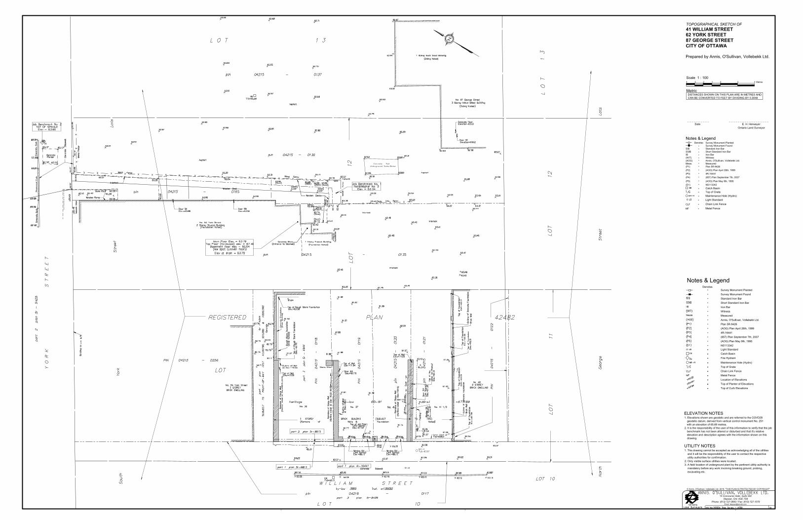
Building is classified as Group : (from table 3.2.2.55)
From Div. B A-3.2.5.7. of the Ontario Building Code - 3. Building On-Site Water Supply:
(a) Q = K x V x Stot
K 16V 4,552
Stot 2.0 Snorth 0 m 0.5Q = 145,650.56 L Seast 6.45 m 0.4
Ssouth 0 m 0.5Swest 15 m 0.0
45001189 gpm
CP-19-0588 - 35-37 William Street - OBC Fire Calculations
Checked By: T.D.F.
L/min (if Q <162,000 L and Q >135,000)
K = water supply coefficient from Table 1
V = total building volume in cubic metres
Stot = total of spatial coefficient values from the property line exposures on all sides as obtained from the formula:
Stot = 1.0 + [Sside1+Sside2+Sside3+…etc.]
where:
Q = minimum supply of water in litres
Ontario 2006 Building Code Compendium (Div. B - Part 3)
Water Supply for Fire-Fighting - Mixed Use Commercial and Residential Building
C and DBuilding is of noncombustible construction with fire separations and fire-resistance ratings provided in accordance withsubsections 3.2.2., including loadbearing walls, columns and arches
Date: December 17, 2019
Project: 35-37 William StreetProject No.: CP-19-0588Designed By: N.B.V.
FromFigure 1(A-32)
(from Table 1 pg A-31) (Worst case occupancy {C/ D} 'K' value used)(Total building volume in m³.)(From figure 1 pg A-32 )
From Table 2: Required Minimum Water Supply Flow Rate (L/s)*approximate distances
____________________________________________________________________________________________________________ 115 Walgreen Road, R.R.3. Carp, ON K0A 1L0 | T. 613-836-2184 | F. 613-836-3742
[email protected] | www.mcintoshperry.com

1 of 2
From Part II – Guide for Determination of Required Fire Flow Copyright I.S.O.:F = 220 x C x √A Where:
F =C =
A =
C = 1.00
As provided by the Architect:Floor Area (Floor One) = 471.52 m²Floor Area (Floor Two) = 471.52 m²
Floor Area (Floor Three) = 365.03 m²Floor Area (Floor Four) = 347.05 m²
A = 1,655.12 m²
From Architectural Drawings:Number of Storeys = 4.00
F = 220 x C x √AF = 220.00 X X √F = 8,950.30 L/min.
From note 2, Page 18 of the Fire Underwriter Survey:C2 and C3No Change
Occupancy Decrease = 0.00 L/min.F = 8,950.30 L/min.
Project:Project No.:Designed By:Checked By:
1655.12
E. Determine Increase or Decrease Based on Occupancy
CP-19-0588 - 35-37 William Street - Fire Underwriters Survey (FUS) Fire Calculations
From the Fire Underwriters Survey (1999)
A. Determine The Coefficient Related To The Type Of Construction
1.00
The building is considered to be of ordinary construction type. Therefore,
Date:
35-37 William StreetCP-19-0588N.B.V.T.D.F.December 17, 2019
D. Calculate Required Fire Flow
The total floor area in square meters (including all storey’s, but excluding basements at least50 percent below grade) in the building being considered.
Required fire flow in liters per minuteCoefficient related to the type of construction.
B. Determine Ground Floor Area
C. Determine Height in Storeys
This floor area represents the final build-out of the development; as outlined on the Site Plan drawing.
____________________________________________________________________________________________________________ 115 Walgreen Road, R.R.3. Carp, ON K0A 1L0 | T. 613-836-2184 | F. 613-836-3742
[email protected] | www.mcintoshperry.com

2 of 2
From note 3, Page 18 of the Fire Underwriter Survey:
•
•
Reduction = 8,950.30 L/min. X
Reduction = 2,685.09 L/min.
From note 4, Page 18 of the Fire Underwriter Survey:
•
•
Increase = 8,950.30 L/min. X
Increase = 6,712.73 L/min.
•
•
F = 8,950.30 L/min. - L/min. + 6,712.73 L/min.F = 12,977.94 L/min.
•
•
•
•
•
F. Determine the Decrease, if any for Sprinkler Protection
30%
75%
2,685.09
H. Determine the Total Fire Demand
To the answer obtained in E, substract the value obtained in F and add the value obtained in G
Fire flow should be no less than 2,000L/min. and the maximum value shoul not exceed 45,000L/min.
CP-19-0588 - 35-37 William Street - Fire Underwriters Survey (FUS) Fire Calculations
The flow requirement may be reduced by up to 50% for complete automatic sprinkler protection depending uponadequacy of the system.The credit for the system will be a maximum of 30% for an adequately designed system conforming to NFPA 13 and otherNFPA sprinkler standards.
Additional credit of 10% if water supply is standard for both the system and fire department hose lines
The entire building will be installed with a fully automated, standardized with the City of Ottawa Fire Department
Therefore, after rounding to the nearest 1,000 L/min, the total required fire flow for the development is 13,000 L/min (3,434 GPM).
If sprinkler system is fully supervised system, an additional 10% credit is granted
Therefore the value obtained in Step E is reduced by 30% (The building is sprinklered with a standard system and firedepartment hose lines)
G. Determine the Total Increase for Exposures
Exposure distance to the existing buildings to the north & south of the proposed building is approximately 0m. East andWest are 6.5m and 15m respectively
There are existing buildings surrounding the remainder of the site that are within 45m.
Therefore the charge for exposure is 75% of the value obtained in Step E.
____________________________________________________________________________________________________________ 115 Walgreen Road, R.R.3. Carp, ON K0A 1L0 | T. 613-836-2184 | F. 613-836-3742
[email protected] | www.mcintoshperry.com

1
Nicholas Vachon
From: Wessel, Shawn <[email protected]>Sent: December 18, 2019 9:24 AMTo: Nicholas VachonCc: Tyler Ferguson; O'Connor, AnnSubject: RE: Boundary Condition Request - 35-37 William StreetAttachments: 35-34 William Dec 2019.pdf
Good morning Mr. Vachon.
Further to your request, please find boundary conditions below:
The following are boundary conditions, HGL, for hydraulic analysis at 35-37 William (zone 1W) assumed to beconnected to the 305mm on William (see attached PDF for location).
Minimum HGL = 107.5m
Maximum HGL = 115.0m
MaxDay + FireFlow (217 L/s) = 104.0m
These are for current conditions and are based on computer model simulation.
Disclaimer: The boundary condition information is based on current operation of the city water distributionsystem. The computer model simulation is based on the best information available at the time. The operationof the water distribution system can change on a regular basis, resulting in a variation in boundary conditions.The physical properties of watermains deteriorate over time, as such must be assumed in the absence of actualfield test data. The variation in physical watermain properties can therefore alter the results of the computermodel simulation.
If you require additional information or clarification, please do not hesitate to contact me anytime.
Thank you
Regards,
Shawn Wessel, A.Sc.T.,rcjiProject Manager - Infrastructure ApprovalsGestionnaire de projet – Approbation des demandes d’infrastructures
Development Review Central Branch | Direction de l’examen des projets d’aménagement, Centrale

2
Planning, Infrastructure and Economic Development Department | Direction générale de la planificationde l’infrastructure et du développement économiqueCity of Ottawa | Ville d'Ottawa110 Laurier Ave. W. | 110, avenue Laurier Ouest, Ottawa ON K1P 1J1(613) 580 2424 Ext. | Poste 33017Int. Mail Code | Code de Courrier Interne [email protected]
P Please consider the environment before printing this email
From: Nicholas Vachon <[email protected]>Sent: December 06, 2019 12:21 PMTo: Wessel, Shawn <[email protected]>Cc: Tyler Ferguson <[email protected]>Subject: Boundary Condition Request - 35-37 William Street
Good Afternoon,
I have conducted water demand and fire flow calculations with the information available and would like to requestboundary conditions for the development located at 35 – 37 William Street.
The development includes adding a new Mixed use Commercial and Residential Building. I have attached a location mapshowing the subject site and the approximate location of the water service as well as the calculations.
Please find the below a summary of the water demands to obtain boundary conditions.
35-37 William StreetType of Development: Mixed Use + Residential
Location of Service: William StreetAmount of Fire Flow Required (FUS): 13,000 L/min
Site Area (ha): 0.05Average Daily Demand (L/sec): 0.11
Maximum Daily Demand (L/sec): 0.25Maximum Hourly Demand (L/sec): 0.54
If you require any further information or have any questions, please feel free to contact me.
Thank you,
Nicholas Vachon, EITEngineering Intern115 Walgreen Road, R.R. 3, Carp, ON K0A 1L0
CAUTION: This email originated from an External Sender. Please do not click links or open attachments unless you recognizethe source.
ATTENTION : Ce courriel provient d’un expéditeur externe. Ne cliquez sur aucun lien et n’ouvrez pas de pièce jointe,excepté si vous connaissez l’expéditeur.

3
T. [email protected] | www.mcintoshperry.com
Confidentiality Notice – If this email wasn’t intended for you, please return or delete it. Click here to read all of the legal language around this concept.
'
This e-mail originates from the City of Ottawa e-mail system. Any distribution, use or copying of this e-mail or theinformation it contains by other than the intended recipient(s) is unauthorized. Thank you.
Le présent courriel a été expédié par le système de courriels de la Ville d'Ottawa. Toute distribution, utilisation oureproduction du courriel ou des renseignements qui s'y trouvent par une personne autre que son destinataire prévu estinterdite. Je vous remercie de votre collaboration.
'


APPENDIX DSANITARY CALCULATIONS

115 Walgreen Road, R.R.3. Carp, ON K0A 1L0 | T. 613-836-2184 | F. [email protected] | www.mcintoshperry.com
Project: CP-19-0588 – 35-37 William StreetDesigned By: NBVChecked By: TDFDate: December 17, 2019
Re: Sanitary Flow Calculations
1. Building Occupancy
The maximum number of bedroom units will be 16 units as per the floors plans and there will be 270 seats inthe restaurant as per the attached unit break down from the Architect.
2. Daily Volume in Litres
As per the extract of the City of Ottawa Sewer Design Guidelines, Appendix 4-A; Daily Sewage Flow forDwellings;
· Each Dwelling unit of 1 bedroom= 275 Liters/Dwelling/Day
· Each Seat in an Ordinary Restaurant= 125 Liters/Seat/Day
3. Peak Flow (Q/p)
· Q1-BED(p) = F1-BED x P1-BED Where:F1-BED = 275 Litres/Dwelling/Day (as per City of Ottawa Sewer DesignGuidelines)P1-BED = 16 Units (as per Site Plan)
· Therefore, Q1-BED(p) = (275) x (16) = 4,400 L/Day (0.051 L/sec)· Q2-RES(p) = FRES x PRES Where:
FRES = 125 Litres/Dwelling/Day (as per City of Ottawa Sewer DesignGuidelines)PRES = 270 Units (as per architect)
· Therefore, Q2-RES(p) = (125) x (270) = 33,750 L/Day (0.391 L/sec)· QTOTAL(p) = Q1-BED + Q2-RES Where:
Q1-BED = 4,400 L/DayQ2-RES = 33,750 L/Day
· Therefore, QTOTAL(p) = (4,400) + (33,750) = 38,150 L/Day (0.442 L/sec)
The capacity of a 250mm sewer with a slope of 0.5% is 43.87 L/s. Therefore, the existing 250mm diameter PVCsanitary main within William Street has the capacity to accommodate the new flows as the additional flow fromthe development is only 1% of the capacity.

SANITARY SEWER DESIGN SHEET
FLOW3 4 5 6 7 8 9 10 11 12 13 14 15 16 17 18 19 20 21 22 23 24 25 26 27 28 29 30 31
AREA PEAK PEAK FLOW DESIGN CAPACITY LENGTH DIA SLOPE VELOCITYFROM TO PEAK FLOW FLOW FLOW (full)
MH MH FACTOR (L/s) IND CUM IND CUM IND CUM (L/s) (L/s) (m/s) L/s (%)
BLD Ex. 250mm 16 0.05 36.8 36.8 4.00 0.05 0.00 0.39 0.39 0.00 0.39 0.05 0.05 0.02 0.46 22.47 8.41 150 2.00 1.232 22.01 97.96
Commercial Flow as per Sanitary Flow Calculations
Design Parameters: Notes: NBV No. 1. Mannings coefficient (n) = 0.013 1. 2. Demand (per capita): 280 L/day
SF 3.4 p/p/u Peak Factor 3. Infiltration allowance: 0.33 L/s/Ha TDFTH/SD 2.7 p/p/u INST 28,000 L/Ha/day 1.5 4. Residential Peaking Factor:
APT 2.3 p/p/u COM 28,000 L/Ha/day 1.5 Harmon Formula = 1+(14/(4+P^0.5)*0.8)Other 60 p/p/Ha IND 35,000 L/Ha/day MOE Chart where P = population in thousands CP-19-0588
SEWER DATAICI AREAS INFILTRATION ALLOWANCE
IND CUM
RESIDENTIAL
SF SD
1 of 1
Project No.:Sheet No:
Checked:
Designed: Date2019-12-18
(L/s) (m) (mm) (%)CUM
RevisionCity Submission #1
CAPACITYINSTITUTIONAL COMMERCIAL INDINDUSTRIALAVAILABLE
(ha) (L/s)TH APT
Residential ICI Areas
PROJECT:LOCATION:
CLIENT:
35-37 William Street Re-Development35-37 William StreetDomenic Santaguida
LOCATION1 2
AREA (ha) AREA (ha)STREET AREA ID
POPULATIONUNIT TYPES
H:\01 Project - Proposals\2019 Jobs\CP\0CP-Projects\0CP-19-0588 Domenic Santaguida_Vittoria Trattoria_35 William St\03 - Servicing\Sanitary\CP-19-0588 - Sanitary Sewer Design Sheet.xlsx 2019-12-189:39 AM

APPENDIX EPRE-DEVELOPMENT DRAINAGE PLAN

Job Benchmark No. 1Nail&Washer No. 5
Elev = 63.34
CBT/G=63.11
MH-HT/G=63.27
LS
115 Walgreen Road, RR3, Carp, ON K0A 1L0Tel: 613-836-2184 Fax: 613-836-3742
www.mcintoshperry.com
FILE
NAM
E: H
:\01
Pro
ject
- Pr
opos
als\
2019
Jobs
\CP\
0CP-
Proj
ects
\0CP
-19-
0588
Dom
enic
San
tagu
ida_
Vitt
oria
Tra
ttor
ia_3
5 W
illia
m S
t\12
- Dr
awin
gs\C
P-19
-058
8 PR
ESEN
TATI
ON
.dw
gLA
ST S
AVED
: Wed
nesd
ay, D
ecem
ber 1
8, 2
019
LAS
T SA
VED
BY: n
.vac
hon
LAST
PLO
TTED
: Wed
nesd
ay, D
ecem
ber 1
8, 2
019
CTB
FIL
E U
SED:
----
Checked By:Drawn by:
Scale:
Client:
Drawing Title:
Drawing Number:
No. DateRevisions
Project Number:
Project:
VITTORIA TRATTORIA 35 WILLIAM STREET, OTTAWA, ON, K1N 6Z9
VITTORIA TRATTORIA35-37 WILLIAM STREET RE-DEVELOPMENT
POST-DEVELOPMENT DRAINAGE AREA PLAN
N.B.V. T.D.F.
1:150 CP-19-0588PRE1 ISSUED FOR REVIEW DEC. 18, 20190 5 10 15 Metres
SCALE 1 : 150
DRAINAGE AREA AREA
5-YEAR RUNOFF COEFFICIENT
100-YEAR RUNOFF COEFFICIENT
B3 0.07ha
0.790.88
Legend:
A1 0.05ha
0.630.71

APPENDIX FPOST-DEVELOPMENT DRAINAGE PLAN

Job Benchmark No. 1Nail&Washer No. 5
Elev = 63.34
CBT/G=63.11
MH-HT/G=63.27
LS
OH
FOU
RTH
FLO
OR
OU
TLIN
E
THIR
D FL
OO
RO
UTL
INE
THIRD AND FOURTHFLOOR OUTLINE
STAIR ROOF
ELEVATORSHAFTROOF
PROPOSED 4-STOREYMIXED USE
COMMERCIAL ANDRESIDENTIAL BUILDING
35-37 WILLIAM STREET16 UNITS
BUILDING AREA= 471.52m2
F.FL.=63.35 / 63.47U.S.F. REFER TO STRUCTURAL
DRAWINGS
RD
RD
RD
RDRDRD
GM
RS RS
115 Walgreen Road, RR3, Carp, ON K0A 1L0Tel: 613-836-2184 Fax: 613-836-3742
www.mcintoshperry.com
FILE
NAM
E: H
:\01
Pro
ject
- Pr
opos
als\
2019
Jobs
\CP\
0CP-
Proj
ects
\0CP
-19-
0588
Dom
enic
San
tagu
ida_
Vitt
oria
Tra
ttor
ia_3
5 W
illia
m S
t\12
- Dr
awin
gs\C
P-19
-058
8 PR
ESEN
TATI
ON
.dw
gLA
ST S
AVED
: Wed
nesd
ay, D
ecem
ber 1
8, 2
019
LAS
T SA
VED
BY: n
.vac
hon
LAST
PLO
TTED
: Wed
nesd
ay, D
ecem
ber 1
8, 2
019
CTB
FIL
E U
SED:
----
Checked By:Drawn by:
Scale:
Client:
Drawing Title:
Drawing Number:
No. DateRevisions
Project Number:
Project:
VITTORIA TRATTORIA 35 WILLIAM STREET, OTTAWA, ON, K1N 6Z9
VITTORIA TRATTORIA35-37 WILLIAM STREET RE-DEVELOPMENT
POST-DEVELOPMENT DRAINAGE AREA PLAN
N.B.V. T.D.F.
1:150 CP-19-0588POST1 ISSUED FOR REVIEW DEC. 18, 20190 5 10 15 Metres
SCALE 1 : 150
DRAINAGE AREA AREA
5-YEAR RUNOFF COEFFICIENT
100-YEAR RUNOFF COEFFICIENT
B3 0.07ha
0.790.88
Legend:
B3 0.03ha
0.901.00
B2 0.00ha
0.901.00
B4 0.00ha
0.901.00
B5 0.00ha
0.901.00
B1 0.01ha
0.901.00

APPENDIX GSTORMWATER MANAGEMENT CALCULATIONS

1 of 11Pre-Development Runoff Coefficient
Impervious Gravel PerviousArea Area Area(m2) (m2) (m2)
A1 0.048 291.97 0.90 0.00 0.60 186.15 0.20 0.63 0.71
Pre-Development Runoff Calculations
5-Year 100-Year 5-Year 100-YearA1 0.048 0.63 0.71 10 104.2 178.6 8.69 16.80
Total 0.048 8.69 16.80
Post-Development Runoff CoefficientImpervious Gravel Pervious
Area Area Area(m2) (m2) (m2)
B1 0.006 59.72 0.90 0.00 0.60 0.00 0.20 0.90 1.00B2 0.002 17.96 0.90 0.00 0.60 0.00 0.20 0.90 1.00B3 0.033 330.98 0.90 0.00 0.60 0.00 0.20 0.90 1.00B4 0.005 48.04 0.90 0.00 0.60 0.00 0.20 0.90 1.00B5 0.002 21.42 0.90 0.00 0.60 0.00 0.20 0.90 1.00
Post-Development Runoff Calculations
5-Year 100-Year 5-Year 100-YearB1 0.006 0.90 1.00 10 104.2 178.6 1.56 2.96B2 0.002 0.90 1.00 10 104.2 178.6 0.47 0.89B3 0.033 0.90 1.00 10 104.2 178.6 8.63 16.43B4 0.005 0.90 1.00 10 104.2 178.6 1.25 2.38B5 0.002 0.90 1.00 10 104.2 178.6 0.56 1.06
Total 0.048 12.46 23.73
Required Restricted Flow
A1 0.048 0.50 10
DrainageArea
Area(ha)
C5-Year
DrainageArea
DrainageArea
Area(ha)
C
CCCCAVG
5-Year
C100-Year
I(mm/hr)
Q(L/s)
Tc(min)
(mm/hr)I
(L/s)Q
CP-19-0588 - 35-37 William Street - Runoff Calculations
C5-Year
Area(ha)
C CCAVG
5-Year
Area(ha)
DrainageArea
Area(ha)
DrainageArea
C100-Year
C5-Year
CAVG
100-Year
CAVG
100-Year
Tc(min)
I
5-Year5-Year
Q(L/s)
6.92104.2
(mm/hr)Tc
(min)
______________________________________________________________________________________________________________ 115 Walgreen Road, R.R.3. Carp, ON K0A 1L0 | T. 613-836-2184 | F. 613-836-3742
[email protected] | www.mcintoshperry.com

2 of 11Post-Development Restricted Runoff Calculations
5-Year 100-Year 5-Year 100-Year 5-Year 100-Year 5-Year 100-YearB1 1.56 2.96 0.30 0.54 0.91 1.77 1.12 2.02 RestrictedB2 0.47 0.89 0.18 0.36 0.17 0.32 0.20 0.40 RestrictedB3 8.63 16.43 1.08 1.80 6.19 12.27 7.45 12.41 RestrictedB4 1.25 2.38 0.24 0.48 0.73 1.35 0.73 1.44 RestrictedB5 0.56 1.06 0.56 1.06 Unrestricted
Total 12.46 23.73 2.36 4.24 8.01 15.71 9.50 16.27
DrainageArea
Unrestricted Flow(L/s)
CP-19-0588 - 35-37 William Street - Runoff Calculations
Storage Required(m3)
Storage Provided(m3)
Restricted Flow(L/s)
______________________________________________________________________________________________________________ 115 Walgreen Road, R.R.3. Carp, ON K0A 1L0 | T. 613-836-2184 | F. 613-836-3742
[email protected] | www.mcintoshperry.com

3 of 11Storage Requirements for Area B15-Year Storm Event
Allowable Runoff to StorageOutflow be Stored Required
(L/s) (L/s) (m3)10 104.2 1.56 0.30 1.26 0.7520 70.3 1.05 0.30 0.75 0.9030 53.9 0.81 0.30 0.51 0.9140 44.2 0.66 0.30 0.36 0.8650 37.7 0.56 0.30 0.26 0.7960 32.9 0.49 0.30 0.19 0.6970 29.4 0.44 0.30 0.14 0.5880 26.6 0.40 0.30 0.10 0.4790 24.3 0.36 0.30 0.06 0.34
100 22.4 0.33 0.30 0.03 0.21
Maximum Storage Required 5-Year (m3) = 0.91100-Year Storm Event
Allowable Runoff to StorageOutflow be Stored Required
(L/s) (L/s) (m3)10 178.6 2.96 0.54 2.42 1.4520 120.0 1.99 0.54 1.45 1.7430 91.9 1.53 0.54 0.99 1.7740 75.1 1.25 0.54 0.71 1.7050 64.0 1.06 0.54 0.52 1.5760 55.9 0.93 0.54 0.39 1.4070 49.8 0.83 0.54 0.29 1.2080 45.0 0.75 0.54 0.21 0.99
Maximum Storage Required 100-Year (m3) = 1.77
Storage Occupied In Area B1
5-Year Storm Event
Roof 44.79 0.025 1.12 1.12Total 1.12 0.91
100-Year Storm Event
Roof 44.79 0.045 2.02 2.02Total 2.02 1.77
*Area is 75% of the total roof area
Storage Available (m³) =Storage Required (m³) =
Storage Available (m³) =Storage Required (m³) =
Roof Storage
Location Area* DepthVolume
(m³)
Roof Storage
Location Area* DepthVolume
(m³)
CP-19-0588 - 35-37 William Street - Runoff Calculations
Tc(min)
I(mm/hr)
B1 Runoff(L/s)
Tc(min)
I(mm/hr)
B1 Runoff(L/s)
______________________________________________________________________________________________________________ 115 Walgreen Road, R.R.3. Carp, ON K0A 1L0 | T. 613-836-2184 | F. 613-836-3742
[email protected] | www.mcintoshperry.com

4 of 11Roof Drain Flow (B1)
Type of Control DeviceNumber of Roof Drians
5-Year 100-Year1.12 2.02
0.025 0.0450.30 0.540.30 0.54
0.18 15 0.180.24 20 0.24
15 0.18 5-Year 0.30 25 0.3020 0.24 0.36 30 0.3625 0.30 0.42 35 0.4230 0.36 0.48 40 0.4835 0.42 100-Year 0.54 45 0.5440 0.48 0.60 50 0.6045 0.54 0.66 55 0.6650 0.60 0.72 60 0.7255 0.66 0.78 65 0.78
0.84 70 0.840.90 75 0.900.96 80 0.961.02 85 1.02
CALCULATING ROOF FLOW EXAMPLES 1.08 90 1.081.14 95 1.14
2 roof drains during a 5 year storm 1.20 100 1.20elevation of water = 30mm 1.26 105 1.26Flow leaving 2 roof drains = (2 x 0.36 L/s) = 0.72 L/s 1.32 110 1.32
1.38 115 1.382 roof drains during a 100 year storm 1.44 120 1.44elevation of water = 45mm 1.50 125 1.50Flow leaving 2 roof drains = (2 x 0.54 L/s) = 1.08 L/s 1.56 130 1.56
1.62 135 1.621.68 140 1.681.74 145 1.741.80 150 1.80
CP-19-0588 - 35-37 William Street - Runoff Calculations
Flow Rate Vs. Build-Up Flow (l/s)Storage Depth
(mm)Drains Flow (l/s)
(One Weir)
Roof Drains SummaryWatts Drianage - Accutrol Weir
1
Note: The flow leaving through a restricted roof drain is based onflow vs. head information
Rooftop Storage (m3)Storage Depth (m)Flow (Per Roof Drain) (L/s)Total Flow (L/s)
Roof Drain Flow
*Roof Drain model to be Accutrol Weirs, See attachedsheets*Roof Drain Flow information taken from Watts Drainagewebsite
Depth (mm) Flow (L/s)
______________________________________________________________________________________________________________ 115 Walgreen Road, R.R.3. Carp, ON K0A 1L0 | T. 613-836-2184 | F. 613-836-3742
[email protected] | www.mcintoshperry.com

5 of 11Storage Requirements for Area B25-Year Storm Event
Allowable Runoff to StorageOutflow be Stored Required
(L/s) (L/s) (m3)10 104.2 0.47 0.18 0.29 0.1720 70.3 0.32 0.18 0.14 0.1630 53.9 0.24 0.18 0.06 0.1140 44.2 0.20 0.18 0.02 0.0450 37.7 0.17 0.18 -0.01 -0.0360 32.9 0.15 0.18 -0.03 -0.12
Maximum Storage Required 5-Year (m3) = 0.17100-Year Storm Event
Allowable Runoff to StorageOutflow be Stored Required
(L/s) (L/s) (m3)10 178.6 0.89 0.36 0.53 0.3220 120.0 0.60 0.36 0.24 0.2930 91.9 0.46 0.36 0.10 0.1840 75.1 0.38 0.36 0.02 0.0450 64.0 0.32 0.36 -0.04 -0.1260 55.9 0.28 0.36 -0.08 -0.29
Maximum Storage Required 100-Year (m3) = 0.32
Storage Occupied In Area B2
5-Year Storm Event
Roof 13.47 0.015 0.20 0.20Total 0.20 0.17
100-Year Storm Event
Roof 13.47 0.030 0.40 0.40Total 0.40 0.32
*Area is 75% of the total roof area
Storage Available (m³) =
CP-19-0588 - 35-37 William Street - Runoff Calculations
Tc(min)
I(mm/hr)
B2 Runoff(L/s)
Tc(min)
I(mm/hr)
B2 Runoff(L/s)
Roof Storage
Location Area DepthVolume
(m³)
Storage Available (m³) =Storage Required (m³) =
Storage Required (m³) =
Roof Storage
Location Area DepthVolume
(m³)
______________________________________________________________________________________________________________ 115 Walgreen Road, R.R.3. Carp, ON K0A 1L0 | T. 613-836-2184 | F. 613-836-3742
[email protected] | www.mcintoshperry.com

6 of 11Roof Drain Flow (B2)
Type of Control DeviceNumber of Roof Drians
5-Year 100-Year0.20 0.40
0.015 0.0300.18 0.360.18 0.36
5-Year 0.18 15 0.180.24 20 0.24
15 0.18 0.30 25 0.3020 0.24 100-Year 0.36 30 0.3625 0.30 0.42 35 0.4230 0.36 0.48 40 0.4835 0.42 0.54 45 0.5440 0.48 0.60 50 0.6045 0.54 0.66 55 0.6650 0.60 0.72 60 0.7255 0.66 0.78 65 0.78
0.84 70 0.840.90 75 0.900.96 80 0.961.02 85 1.02
CALCULATING ROOF FLOW EXAMPLES 1.08 90 1.081.14 95 1.14
3 roof drains during a 5 year storm 1.20 100 1.20elevation of water = 55mm 1.26 105 1.26Flow leaving 4 roof drains = (3 x 0.66 L/s) = 1.98 L/s 1.32 110 1.32
1.38 115 1.383 roof drains during a 100 year storm 1.44 120 1.44elevation of water = 85mm 1.50 125 1.50Flow leaving 4 roof drains = (3 x 1.02 L/s) = 3.06 L/s 1.56 130 1.56
1.62 135 1.621.68 140 1.681.74 145 1.741.80 150 1.80
Storage Depth (m)
CP-19-0588 - 35-37 William Street - Runoff Calculations
Rooftop Storage (m3)
Watts Drianage - Accutrol Weir1
Roof Drains Summary
Flow (Per Roof Drain) (L/s)Total Flow (L/s)
Roof Drain FlowFlow Rate Vs. Build-Up Flow (l/s)
Storage Depth(mm)
Drains Flow (l/s)(One Weir)
Depth (mm) Flow (L/s)
*Roof Drain model to be Accutrol Weirs, See attachedsheets*Roof Drain Flow information taken from Watts Drainagewebsite
Note: The flow leaving through a restricted roof drain is based onflow vs. head information
______________________________________________________________________________________________________________ 115 Walgreen Road, R.R.3. Carp, ON K0A 1L0 | T. 613-836-2184 | F. 613-836-3742
[email protected] | www.mcintoshperry.com

7 of 11Storage Requirements for Area B35-Year Storm Event
Allowable Runoff to StorageOutflow be Stored Required
(L/s) (L/s) (m3)10 104.2 8.63 1.08 7.55 4.5320 70.3 5.82 1.08 4.74 5.6930 53.9 4.47 1.08 3.39 6.0940 44.2 3.66 1.08 2.58 6.1950 37.7 3.12 1.08 2.04 6.1160 32.9 2.73 1.08 1.65 5.93
Maximum Storage Required 5-Year (m3) = 6.19100-Year Storm Event
Allowable Runoff to StorageOutflow be Stored Required
(L/s) (L/s) (m3)10 178.6 16.43 1.80 14.63 8.7820 120.0 11.04 1.80 9.24 11.0830 91.9 8.45 1.80 6.65 11.9840 75.1 6.91 1.80 5.11 12.2750 64.0 5.88 1.80 4.08 12.2560 55.9 5.14 1.80 3.34 12.03
Maximum Storage Required 100-Year (m3) = 12.27
Storage Occupied In Area B3
5-Year Storm Event
Roof 248.24 0.030 7.45 7.45Total 7.45 6.19
100-Year Storm Event
Roof 248.24 0.050 12.41 12.41Total 12.41 12.27
*Area is 75% of the total roof area
Storage Available (m³) =Storage Required (m³) =
Storage Required (m³) =
Roof Storage
Location Area DepthVolume
(m³)
Storage Available (m³) =
CP-19-0588 - 35-37 William Street - Runoff Calculations
Tc(min)
I(mm/hr)
B3 Runoff(L/s)
Tc(min)
I(mm/hr)
B3 Runoff(L/s)
Roof Storage
Location Area DepthVolume
(m³)
______________________________________________________________________________________________________________ 115 Walgreen Road, R.R.3. Carp, ON K0A 1L0 | T. 613-836-2184 | F. 613-836-3742
[email protected] | www.mcintoshperry.com

8 of 11Roof Drain Flow (B3)
Type of Control DeviceNumber of Roof Drians
5-Year 100-Year7.45 12.41
0.030 0.0500.36 0.601.08 1.80
0.18 15 0.540.24 20 0.72
15 0.18 0.30 25 0.9020 0.24 5-Year 0.36 30 1.0825 0.30 0.42 35 1.2630 0.36 0.48 40 1.4435 0.42 0.54 45 1.6240 0.48 100-Year 0.60 50 1.8045 0.54 0.66 55 1.9850 0.60 0.72 60 2.1655 0.66 0.78 65 2.34
0.84 70 2.520.90 75 2.700.96 80 2.881.02 85 3.06
CALCULATING ROOF FLOW EXAMPLES 1.08 90 3.241.14 95 3.42
4 roof drains during a 5 year storm 1.20 100 3.60elevation of water = 50mm 1.26 105 3.78Flow leaving 4 roof drains = (4 x 0.60 L/s) = 2.40 L/s 1.32 110 3.96
1.38 115 4.144 roof drains during a 100 year storm 1.44 120 4.32elevation of water = 75mm 1.50 125 4.50Flow leaving 4 roof drains = (4 x 0.90 L/s) = 3.60 L/s 1.56 130 4.68
1.62 135 4.861.68 140 5.041.74 145 5.221.80 150 5.40
Depth (mm) Flow (L/s)
*Roof Drain model to be Accutrol Weirs, See attachedsheets*Roof Drain Flow information taken from Watts Drainagewebsite
Note: The flow leaving through a restricted roof drain is based onflow vs. head information
Flow (Per Roof Drain) (L/s)Total Flow (L/s)
Roof Drain FlowFlow Rate Vs. Build-Up Flow (l/s)
Storage Depth(mm)
Drains Flow (l/s)(One Weir)
Storage Depth (m)
CP-19-0588 - 35-37 William Street - Runoff Calculations
Rooftop Storage (m3)
Watts Drianage - Accutrol Weir3
Roof Drains Summary
______________________________________________________________________________________________________________ 115 Walgreen Road, R.R.3. Carp, ON K0A 1L0 | T. 613-836-2184 | F. 613-836-3742
[email protected] | www.mcintoshperry.com

9 of 11Storage Requirements for Area B45-Year Storm Event
Allowable Runoff to StorageOutflow be Stored Required
(L/s) (L/s) (m3)10 104.2 1.25 0.24 1.01 0.6120 70.3 0.84 0.24 0.60 0.7330 53.9 0.65 0.24 0.41 0.7340 44.2 0.53 0.24 0.29 0.7050 37.7 0.45 0.24 0.21 0.6460 32.9 0.40 0.24 0.16 0.56
Maximum Storage Required 5-Year (m3) = 0.73100-Year Storm Event
Allowable Runoff to StorageOutflow be Stored Required
(L/s) (L/s) (m3)10 178.6 2.38 0.48 1.90 1.1420 120.0 1.60 0.48 1.12 1.3530 91.9 1.23 0.48 0.75 1.3440 75.1 1.00 0.48 0.52 1.2650 64.0 0.85 0.48 0.37 1.1260 55.9 0.75 0.48 0.27 0.96
Maximum Storage Required 100-Year (m3) = 1.35
Storage Occupied In Area B4
5-Year Storm Event
Roof 36.03 0.020 0.73 0.73Total 0.73 0.73
100-Year Storm Event
Roof 36.03 0.040 1.44 1.44Total 1.44 1.35
*Area is 75% of the total roof area
Storage Available (m³) =Storage Required (m³) =
Storage Required (m³) =
Roof Storage
Location Area DepthVolume
(m³)
Storage Available (m³) =
CP-19-0588 - 35-37 William Street - Runoff Calculations
Tc(min)
I(mm/hr)
B4 Runoff(L/s)
Tc(min)
I(mm/hr)
B4 Runoff(L/s)
Roof Storage
Location Area DepthVolume
(m³)
______________________________________________________________________________________________________________ 115 Walgreen Road, R.R.3. Carp, ON K0A 1L0 | T. 613-836-2184 | F. 613-836-3742
[email protected] | www.mcintoshperry.com

10 of 11Roof Drain Flow (B4)
Type of Control DeviceNumber of Roof Drians
5-Year 100-Year0.73 1.44
0.020 0.0400.24 0.480.24 0.48
0.18 15 0.185-Year 0.24 20 0.24
15 0.18 0.30 25 0.3020 0.24 0.36 30 0.3625 0.30 0.42 35 0.4230 0.36 100-Year 0.48 40 0.4835 0.42 0.54 45 0.5440 0.48 0.60 50 0.6045 0.54 0.66 55 0.6650 0.60 0.72 60 0.7255 0.66 0.78 65 0.78
0.84 70 0.840.90 75 0.900.96 80 0.961.02 85 1.02
CALCULATING ROOF FLOW EXAMPLES 1.08 90 1.081.14 95 1.14
4 roof drains during a 5 year storm 1.20 100 1.20elevation of water = 50mm 1.26 105 1.26Flow leaving 4 roof drains = (4 x 0.60 L/s) = 2.40 L/s 1.32 110 1.32
1.38 115 1.384 roof drains during a 100 year storm 1.44 120 1.44elevation of water = 75mm 1.50 125 1.50Flow leaving 4 roof drains = (4 x 0.90 L/s) = 3.60 L/s 1.56 130 1.56
1.62 135 1.621.68 140 1.681.74 145 1.741.80 150 1.80
Depth (mm) Flow (L/s)
*Roof Drain model to be Accutrol Weirs, See attachedsheets*Roof Drain Flow information taken from Watts Drainagewebsite
Note: The flow leaving through a restricted roof drain is based onflow vs. head information
Flow (Per Roof Drain) (L/s)Total Flow (L/s)
Roof Drain FlowFlow Rate Vs. Build-Up Flow (l/s)
Storage Depth(mm)
Drains Flow (l/s)(One Weir)
Storage Depth (m)
CP-19-0588 - 35-37 William Street - Runoff Calculations
Rooftop Storage (m3)
Watts Drianage - Accutrol Weir1
Roof Drains Summary
______________________________________________________________________________________________________________ 115 Walgreen Road, R.R.3. Carp, ON K0A 1L0 | T. 613-836-2184 | F. 613-836-3742
[email protected] | www.mcintoshperry.com

11 of 11Time of Concentration Pre-DevelopmentDrainage Area
IDSheet Flow
Distance (m)Slope ofLand (%)
Tc (min)(5-Year)
Tc (min)(100-Year)
A1 18 0.60 5 4 Therefore, a Tc of 10 can be used
Tc= (3.26(1.1-c)L^0.5/S^0.33)c= Blanced Runoff CoefficientL= Length of drainage areaS= Average slope of watershed
CP-19-0588 - 35-37 William Street - Runoff Calculations
______________________________________________________________________________________________________________ 115 Walgreen Road, R.R.3. Carp, ON K0A 1L0 | T. 613-836-2184 | F. 613-836-3742
[email protected] | www.mcintoshperry.com

STORM SEWER DESIGN SHEETPROJECT: 289 Carling Avenue
LOCATION: Ottawa, OntarioCLIENT: John Howard Society
1 2 3 4 5 6 7 8 9 10 11 12 13 14 15 16 17 18 19 20 21 22 23 24 25 26 27 28 29 30 31 32FROM TO INDIV CUMUL INLET TIME TOTAL i (5) i (10) i (100) 5yr PEAK 10yr PEAK 100yr PEAK FIXED DESIGN CAPACITY LENGTH SLOPE VELOCITY
MH MH 0.20 0.60 0.79 0.85 0.87 0.90 AC AC (min) IN PIPE (min) (mm/hr) (mm/hr) (mm/hr) FLOW (L/s) FLOW (L/s) FLOW (L/s) FLOW (L/s) FLOW (L/s) (L/s) (m) DIA W H (%) (m/s) (L/s) (%)
B1 - B4 BLDG Tee 0.05 0.04 0.04 10.00 0.13 10.13 104.19 122.14 178.56 12.46 12.46 22.47 9.59 150 2.00 1.232 10.00 44.53%
Definitions: Notes: No. Q = 2.78CiA, where: 1. Mannings coefficient (n) = 0.013 N.V.B. 1. Q = Peak Flow in Litres per Second (L/s) A = Area in Hectares (ha) i = Rainfall intensity in millimeters per hour (mm/hr) T.D.F. [i = 998.071 / (TC+6.053)^0.814] 5 YEAR [i = 1174.184 / (TC+6.014)^0.816] 10 YEAR [i = 1735.688 / (TC+6.014)^0.820] 100 YEAR CP-19-0007
Project No.:
Date
Sheet No:1 of 1
Checked:
Issued for review
LOCATION SEWER DATA
RevisionDesigned:
RATIONAL DESIGN FLOWCONTRIBUTING AREA (ha)
AVAIL CAP (5yr)STREET AREA ID PIPE SIZE (mm)C-VALUE
2019-12-12
H:\01 Project - Proposals\2019 Jobs\CP\0CP-Projects\0CP-19-0588 Domenic Santaguida_Vittoria Trattoria_35 William St\03 - Servicing\Storm\CP-19-0588 Storm_Design.xlsx

APPENDIX HCITY OF OTTAWA DESIGN CHECKLIST

City of Ottawa
4. Development Servicing Study Checklist
The following section describes the checklist of the required content of servicing studies. It is expected that theproponent will address each one of the following items for the study to be deemed complete and ready for review byCity of Ottawa Infrastructure Approvals staff.
The level of required detail in the Servicing Study will increase depending on the type of application. For example, forOfficial Plan amendments and re-zoning applications, the main issues will be to determine the capacity requirementsfor the proposed change in land use and confirm this against the existing capacity constraint, and to define thesolutions, phasing of works and the financing of works to address the capacity constraint. For subdivisions and siteplans, the above will be required with additional detailed information supporting the servicing within the developmentboundary.
4.1 General Content
Criteria Location (if applicable)
�Executive Summary (for larger reports only). N/A
�Date and revision number of the report. On Cover
�Location map and plan showing municipal address, boundary,and layout of proposed development.
Appendix E
�Plan showing the site and location of all existing services. Site Servicing Plan (C102)
�Development statistics, land use, density, adherence to zoningand official plan, and reference to applicable subwatershed andwatershed plans that provide context to which individualdevelopments must adhere.
1.1 Purpose
1.2 Site Description
6.0 Stormwater Management
�Summary of pre-consultation meetings with City and otherapproval agencies.
Appendix A
�Reference and confirm conformance to higher level studies andreports (Master Servicing Studies, Environmental Assessments,Community Design Plans), or in the case where it is not inconformance, the proponent must provide justification anddevelop a defendable design criteria.
1.1 Purpose
1.2 Site Description
6.0 Stormwater Management
�Statement of objectives and servicing criteria. 3.0 Pre-Consultation Summary

�Identification of existing and proposed infrastructure availablein the immediate area.
N/A
�Identification of Environmentally Significant Areas,watercourses and Municipal Drains potentially impacted by theproposed development (Reference can be made to the NaturalHeritage Studies, if available).
Site Grading, Drainage, Sediment& Erosion Control Plan (C101)
�Concept level master grading plan to confirm existing andproposed grades in the development. This is required toconfirm the feasibility of proposed stormwater managementand drainage, soil removal and fill constraints, and potentialimpacts to neighbouring properties. This is also required toconfirm that the proposed grading will not impede existingmajor system flow paths.
Site Grading, Drainage, Sediment& Erosion Control Plan (C101)
�Identification of potential impacts of proposed piped serviceson private services (such as wells and septic fields on adjacentlands) and mitigation required to address potential impacts.
N/A
�Proposed phasing of the development, if applicable. N/A
�Reference to geotechnical studies and recommendationsconcerning servicing.
Section 2.0 Backround Studies
�All preliminary and formal site plan submissions should havethe following information:
o Metric scaleo North arrow (including construction North)o Key plano Name and contact information of applicant and property
ownero Property limits including bearings and dimensionso Existing and proposed structures and parking areaso Easements, road widening and rights-of-wayo Adjacent street names
Site Grading, Drainage, Sediment& Erosion Control Plan (C101)

4.2 Development Servicing Report: Water
Criteria Location (if applicable)�Confirm consistency with Master Servicing Study, if available N/A
�Availability of public infrastructure to service proposeddevelopment
N/A
�Identification of system constraints N/A
�Identify boundary conditions N/A
�Confirmation of adequate domestic supply and pressure N/A
�Confirmation of adequate fire flow protection and confirmationthat fire flow is calculated as per the Fire Underwriter’s Survey.Output should show available fire flow at locations throughoutthe development.
Appendix B
�Provide a check of high pressures. If pressure is found to behigh, an assessment is required to confirm the application ofpressure reducing valves.
N/A
�Definition of phasing constraints. Hydraulic modeling isrequired to confirm servicing for all defined phases of theproject including the ultimate design
N/A
�Address reliability requirements such as appropriate location ofshut-off valves
N/A
�Check on the necessity of a pressure zone boundarymodification.
N/A
�Reference to water supply analysis to show that majorinfrastructure is capable of delivering sufficient water for theproposed land use. This includes data that shows that theexpected demands under average day, peak hour and fire flowconditions provide water within the required pressure range
N/A

�Description of the proposed water distribution network,including locations of proposed connections to the existingsystem, provisions for necessary looping, and appurtenances(valves, pressure reducing valves, valve chambers, and firehydrants) including special metering provisions.
N/A
�Description of off-site required feedermains, booster pumpingstations, and other water infrastructure that will be ultimatelyrequired to service proposed development, including financing,interim facilities, and timing of implementation.
N/A
�Confirmation that water demands are calculated based on theCity of Ottawa Design Guidelines.
Appendix B
�Provision of a model schematic showing the boundaryconditions locations, streets, parcels, and building locations forreference.
N/A
4.3 Development Servicing Report: Wastewater
Criteria Location (if applicable)�Summary of proposed design criteria (Note: Wet-weather flow
criteria should not deviate from the City of Ottawa SewerDesign Guidelines. Monitored flow data from relatively newinfrastructure cannot be used to justify capacity requirementsfor proposed infrastructure).
N/A
�Confirm consistency with Master Servicing Study and/orjustifications for deviations.
N/A
�Consideration of local conditions that may contribute toextraneous flows that are higher than the recommended flowsin the guidelines. This includes groundwater and soilconditions, and age and condition of sewers.
N/A
�Description of existing sanitary sewer available for discharge ofwastewater from proposed development.
Section 5.2 Sanitary Sewer

�Verify available capacity in downstream sanitary sewer and/oridentification of upgrades necessary to service the proposeddevelopment. (Reference can be made to previously completedMaster Servicing Study if applicable)
N/A
�Calculations related to dry-weather and wet-weather flow ratesfrom the development in standard MOE sanitary sewer designtable (Appendix ‘C’) format.
N/A
�Description of proposed sewer network including sewers,pumping stations, and forcemains.
Section 5.2 Sanitary Sewer
�Discussion of previously identified environmental constraintsand impact on servicing (environmental constraints are relatedto limitations imposed on the development in order topreserve the physical condition of watercourses, vegetation,soil cover, as well as protecting against water quantity andquality).
N/A
�Pumping stations: impacts of proposed development onexisting pumping stations or requirements for new pumpingstation to service development.
N/A
�Forcemain capacity in terms of operational redundancy, surgepressure and maximum flow velocity.
N/A
�Identification and implementation of the emergency overflowfrom sanitary pumping stations in relation to the hydraulicgrade line to protect against basement flooding.
N/A
�Special considerations such as contamination, corrosiveenvironment etc.
N/A

4.4 Development Servicing Report: Stormwater Checklist
Criteria Location (if applicable)�Description of drainage outlets and downstream constraints
including legality of outlets (i.e. municipal drain, right-of-way,watercourse, or private property)
Section 6.0 StormwaterManagement
�Analysis of available capacity in existing public infrastructure. N/A
�A drawing showing the subject lands, its surroundings, thereceiving watercourse, existing drainage patterns, andproposed drainage pattern.
Pre & Post-Development Plans
�Water quantity control objective (e.g. controlling post-development peak flows to pre-development level for stormevents ranging from the 2 or 5-year event (dependent on thereceiving sewer design) to 100-year return period); if otherobjectives are being applied, a rationale must be included withreference to hydrologic analyses of the potentially affectedsubwatersheds, taking into account long-term cumulativeeffects.
Section 6.0 StormwaterManagement
�Water Quality control objective (basic, normal or enhancedlevel of protection based on the sensitivities of the receivingwatercourse) and storage requirements.
Section 6.0 StormwaterManagement
�Description of the stormwater management concept withfacility locations and descriptions with references andsupporting information.
Section 6.0 StormwaterManagement
�Set-back from private sewage disposal systems. N/A
�Watercourse and hazard lands setbacks. N/A
�Record of pre-consultation with the Ontario Ministry ofEnvironment and the Conservation Authority that hasjurisdiction on the affected watershed.
N/A
�Confirm consistency with sub-watershed and Master ServicingStudy, if applicable study exists.
N/A
�Storage requirements (complete with calculations) andconveyance capacity for minor events (1:5-year return period)and major events (1:100-year return period).
Appendix F

�Identification of watercourses within the proposeddevelopment and how watercourses will be protected, or, ifnecessary, altered by the proposed development withapplicable approvals.
Site Grading, Drainage, Sediment& Erosion Control Plan
�Calculate pre-and post development peak flow rates including adescription of existing site conditions and proposed imperviousareas and drainage catchments in comparison to existingconditions.
Section 6.0 StormwaterManagement
Appendix F
�Any proposed diversion of drainage catchment areas from oneoutlet to another.
Section 6.0 StormwaterManagement
�Proposed minor and major systems including locations andsizes of stormwater trunk sewers, and stormwatermanagement facilities.
Section 6.0 StormwaterManagement
�If quantity control is not proposed, demonstration thatdownstream system has adequate capacity for the post-development flows up to and including the 100-year returnperiod storm event.
Appendix A
�Identification of potential impacts to receiving watercourses N/A
�Identification of municipal drains and related approvalrequirements.
N/A
�Descriptions of how the conveyance and storage capacity willbe achieved for the development.
Section 6.0 StormwaterManagement
�100-year flood levels and major flow routing to protectproposed development from flooding for establishing minimumbuilding elevations (MBE) and overall grading.
Site Grading, Drainage, Sediment& Erosion Control Plan (C101)
�Inclusion of hydraulic analysis including hydraulic grade lineelevations.
N/A

�Description of approach to erosion and sediment control duringconstruction for the protection of receiving watercourse ordrainage corridors.
Section 7.0 Sediment & ErosionControl
�Identification of floodplains – proponent to obtain relevantfloodplain information from the appropriate ConservationAuthority. The proponent may be required to delineatefloodplain elevations to the satisfaction of the ConservationAuthority if such information is not available or if informationdoes not match current conditions.
N/A
�Identification of fill constraints related to floodplain andgeotechnical investigation.
N/A
4.5 Approval and Permit Requirements: Checklist
The Servicing Study shall provide a list of applicable permits and regulatory approvals necessary for theproposed development as well as the relevant issues affecting each approval. The approval and permittingshall include but not be limited to the following:
Criteria Location (if applicable)�Conservation Authority as the designated approval agency for
modification of floodplain, potential impact on fish habitat,proposed works in or adjacent to a watercourse, cut/fillpermits and Approval under Lakes and Rivers ImprovementAct. The Conservation Authority is not the approval authorityfor the Lakes and Rivers Improvement Act. Where there areConservation Authority regulations in place, approval under theLakes and Rivers Improvement Act is not required, except incases of dams as defined in the Act.
N/A
�Application for Certificate of Approval (CofA) under the OntarioWater Resources Act.
N/A
�Changes to Municipal Drains. N/A
�Other permits (National Capital Commission, Parks Canada,Public Works and Government Services Canada, Ministry ofTransportation etc.)
N/A

4.6 Conclusion Checklist
Criteria Location (if applicable)�Clearly stated conclusions and recommendations Section 8.0 Summary
Section 9.0 Recommendations
�Comments received from review agencies including the City ofOttawa and information on how the comments wereaddressed. Final sign-off from the responsible reviewingagency.
All are stamped
�All draft and final reports shall be signed and stamped by aprofessional Engineer registered in Ontario
All are stamped