Embed Size (px)
Citation preview
Gearmotors \ Industrial Gear Units \ Drive Electronics \ Drive Automation \ Services
Explosion-Proof VARIBLOC® Variable Speed Gear Units and Accessories
Operating InstructionsEdition 11/200611528613 / EN

SEW-EURODRIVE – Driving the world
Operating Instructions – Explosion-proof VARIBLOC® Variable Speed Gear Units and Accessories 3
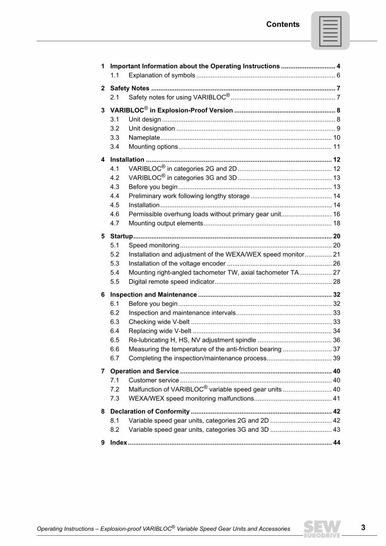
Contents
1 Important Information about the Operating Instructions .............................. 41.1 Explanation of symbols ............................................................................. 6
2 Safety Notes ...................................................................................................... 72.1 Safety notes for using VARIBLOC® .......................................................... 7
3 VARIBLOC® in Explosion-Proof Version ........................................................ 83.1 Unit design ................................................................................................ 83.2 Unit designation ........................................................................................ 93.3 Nameplate............................................................................................... 103.4 Mounting options..................................................................................... 11
4 Installation ....................................................................................................... 124.1 VARIBLOC® in categories 2G and 2D .................................................... 124.2 VARIBLOC® in categories 3G and 3D .................................................... 134.3 Before you begin..................................................................................... 134.4 Preliminary work following lengthy storage............................................. 144.5 Installation............................................................................................... 144.6 Permissible overhung loads without primary gear unit............................ 164.7 Mounting output elements....................................................................... 18
5 Startup.............................................................................................................. 205.1 Speed monitoring.................................................................................... 205.2 Installation and adjustment of the WEXA/WEX speed monitor............... 215.3 Installation of the voltage encoder .......................................................... 265.4 Mounting right-angled tachometer TW, axial tachometer TA.................. 275.5 Digital remote speed indicator................................................................. 28
6 Inspection and Maintenance .......................................................................... 326.1 Before you begin..................................................................................... 326.2 Inspection and maintenance intervals..................................................... 336.3 Checking wide V-belt .............................................................................. 336.4 Replacing wide V-belt ............................................................................. 346.5 Re-lubricating H, HS, NV adjustment spindle ......................................... 366.6 Measuring the temperature of the anti-friction bearing ........................... 376.7 Completing the inspection/maintenance process.................................... 39
7 Operation and Service .................................................................................... 407.1 Customer service .................................................................................... 407.2 Malfunction of VARIBLOC® variable speed gear units ........................... 407.3 WEXA/WEX speed monitoring malfunctions........................................... 41
8 Declaration of Conformity .............................................................................. 428.1 Variable speed gear units, categories 2G and 2D .................................. 428.2 Variable speed gear units, categories 3G and 3D .................................. 43
9 Index................................................................................................................. 44
1 mportant Information about the Operating Instructions
4
1 Important Information about the Operating InstructionsIntroduction You must adhere to the information in the operating instructions to ensure fault-free
operation and for the fulfillment of any rights to claim under the limited warranty. Readthe operating instructions before you start working with the unit.Make sure that the operating instructions are available to persons responsible for thesystem and its operation, as well as to persons who work independently on the unit.Also observe other technical documents, contracts for delivery or other agreements.
Designated useThe VARIBLOC® variable speed gear units are intended for commercial and industrialsystems and may only be used in accordance with the information provided in SEW-EURODRIVE's technical documentation and the information given on the nameplate.It corresponds to valid standards and regulations and meet the requirements ofEC Directive 94/9/EC and the EC Directive for Machinery 98/37/EC. Gear unit loads other than those specified and areas of application other than industrialand commercial systems can only be used after consultation with SEW-EURODRIVE.Any application other than those mentioned is considered non-designated use.A drive motor connected to the VARIBLOC® may not be operated on the frequencyinverter.
Qualified personnelVARIBLOC® variable speed gear units represent a potential hazard for persons andmaterial. Consequently, assembly, installation, startup and service work may only beperformed by trained personnel who are aware of the potential hazards.Personnel must possess the required qualifications for the relevant task and be familiarwith the: • Assembly• Installation• Startup• Operation• Maintenance• Servicingof the product.Personnel must carefully read the operating instructions, in particular the safety notessection, and understand and comply with them.
I
Operating Instructions – Explosion-proof VARIBLOC® Variable Speed Gear Units and Accessories
1Important Information about the Operating Instructions
Exclusion of liabilityYou must comply with the information contained in these operating instructions toensure safe operation of the VARIBLOC® variable speed gear unit and to achieve thespecified product characteristics and performance requirements.SEW-EURODRIVE GmbH & Co KG assumes no liability for injury to persons or damageto equipment or property resulting from non-observance of these operating instructions.In such cases, any liability for defects is excluded.
Product names and trademarksThe brands and product names contained within these operating instructions are trade-marks or registered trademarks of the titleholders.
Disposal (Please follow the current instructions):• Housing parts, gears, shafts and anti-friction bearings of the gear unit must be
disposed of as steel scrap. This also applies to gray-cast iron parts if there is nospecial collection.
• Collect waste oil and dispose of it according to the regulations in force.
Operating Instructions – Explosion-proof VARIBLOC® Variable Speed Gear Units and Accessories
5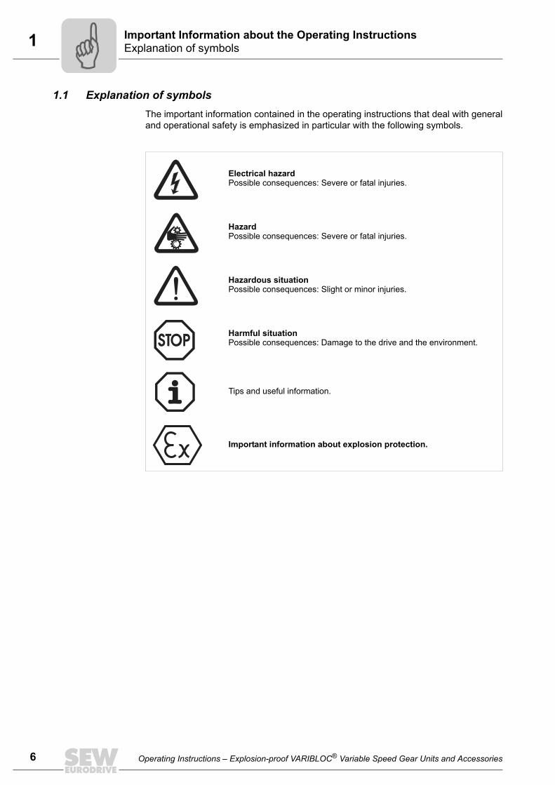
1 mportant Information about the Operating Instructionsxplanation of symbols
6
1.1 Explanation of symbolsThe important information contained in the operating instructions that deal with generaland operational safety is emphasized in particular with the following symbols.
Electrical hazardPossible consequences: Severe or fatal injuries.
HazardPossible consequences: Severe or fatal injuries.
Hazardous situationPossible consequences: Slight or minor injuries.
Harmful situationPossible consequences: Damage to the drive and the environment.
Tips and useful information.
Important information about explosion protection.
IE
Operating Instructions – Explosion-proof VARIBLOC® Variable Speed Gear Units and Accessories
2Safety notes for using VARIBLOC®
Safety Notes
2 Safety Notes2.1 Safety notes for using VARIBLOC®
The following safety notes apply to variable speed gear units.
Optional equipment
Technical data and information on approved conditions on site can be found on thenameplate and in this manual.You must comply with this information.
When using variable speed gearmotors, also refer to the safety notes for gear unitsand motors in the relevant operating instructions. Take into consideration the supple-mentary safety notes in the individual sections of these operating instructions.
Explosive gas mixtures or dust concentrations when combined with hot, live, andmoving parts of electrical machinery can cause serious injury or death.
Only qualified personnel may perform assembly, connection, startup, mainte-nance, and repair work on the VARIBLOC® variable speed gear unit while takingthe following into account:• These operating instructions• The warning and instruction labels on the variable speed gear unit/variable speed
gearmotor• All other project planning documentation, startup instructions and wiring diagrams• The specific regulations and requirements for the system• The current national/regional regulations in effect
Optional equipment complies with existing standards and regulations:• EN50014• EN50018 for protection type "d"• EN50019 for protection type "e"• EN50020 intrinsically safe "i"• EN 50281-1-1/EN 50281-1-2 "Electrical apparatus for use in the presence of com-
bustible dust"In addition to general installation guidelines, the following regulations in accordance withElexV 1 (or other national regulations) must be observed for electrically operatedoptions:• EN 60 079-14 "Electrical apparatus for explosive gas atmospheres"• EN 50281-1-2 "Electrical apparatus for use in the presence of combustible dust"• DIN VDE 105-9 "Operating electrical equipment" or other national regulations• DIN VDE 0100 "Erection of power installations with rated voltages below 1000 V" or
other national regulations• System-specific regulations
Operating Instructions – Explosion-proof VARIBLOC® Variable Speed Gear Units and Accessories
7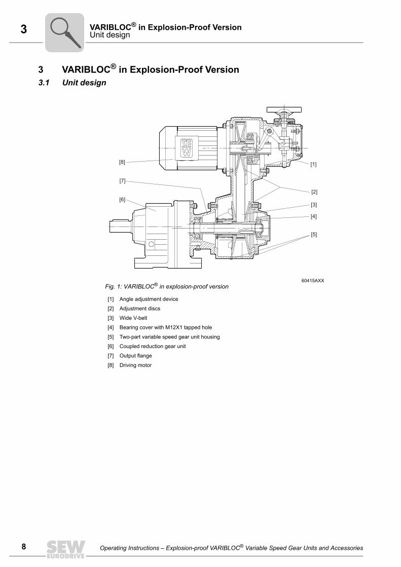
3 ARIBLOC® in Explosion-Proof Versionnit design
8
3 VARIBLOC® in Explosion-Proof Version3.1 Unit design
60415AXXFig. 1: VARIBLOC® in explosion-proof version
[1] Angle adjustment device
[2] Adjustment discs
[3] Wide V-belt
[4] Bearing cover with M12X1 tapped hole
[5] Two-part variable speed gear unit housing
[6] Coupled reduction gear unit
[7] Output flange
[8] Driving motor
[8]
[7]
[1]
[2]
[3]
[5]
[4]
[6]
VU
Operating Instructions – Explosion-proof VARIBLOC® Variable Speed Gear Units and Accessories
3VARIBLOC® in Explosion-Proof VersionUnit designation
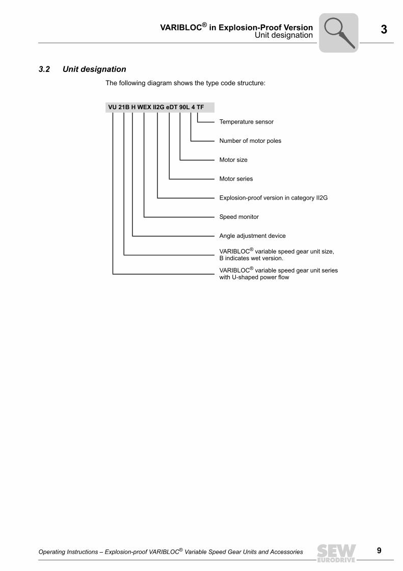
3.2 Unit designationThe following diagram shows the type code structure:
VU 21B H WEX II2G eDT 90L 4 TF
Temperature sensor
Number of motor poles
Motor size
Motor series
Explosion-proof version in category II2G
Speed monitor
Angle adjustment device
VARIBLOC® variable speed gear unit size, B indicates wet version.
VARIBLOC® variable speed gear unit series with U-shaped power flow
Operating Instructions – Explosion-proof VARIBLOC® Variable Speed Gear Units and Accessories
9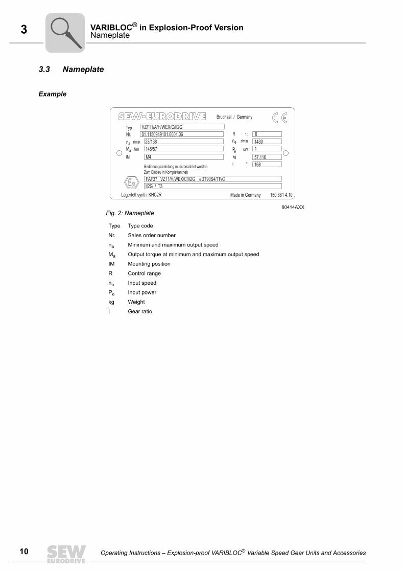
3 ARIBLOC® in Explosion-Proof Versionameplate
10
3.3 Nameplate
Example
60414AXXFig. 2: Nameplate
Type Type code
Nr. Sales order number
na Minimum and maximum output speed
Ma Output torque at minimum and maximum output speed
IM Mounting position
R Control range
ne Input speed
Pe Input power
kg Weight
i Gear ratio
TypNr.
na r/min
Ma Nm
IM
R
ne r/min
Pekg
1:
kW
i =Bedienungsanleitung muss beachtet werden
Zum Einbau in Komplettantrieb
Lagerfett synth. KHC2R Made in Germany 150 881 4.10
VZF11/A/H/WEX/C/II2G
01.1150949101.0001.06
23/138
148/57
M4
6
1430
1
57.110
FAF37 VZ11/H/WEX/C/II2G eDT90S4/TF/C
II2G / T3
Bruchsal / Germany
168
VN
Operating Instructions – Explosion-proof VARIBLOC® Variable Speed Gear Units and Accessories
3VARIBLOC® in Explosion-Proof VersionMounting options
]
1]
]
]
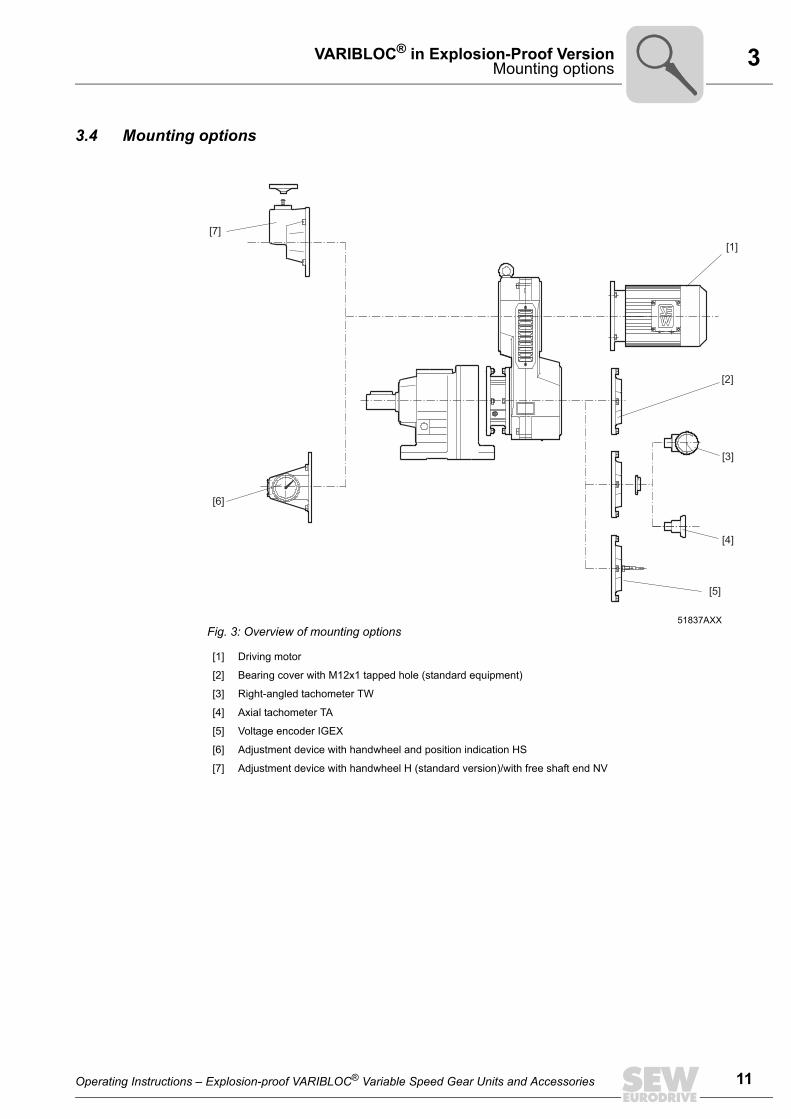
3.4 Mounting options
51837AXXFig. 3: Overview of mounting options
[1] Driving motor
[2] Bearing cover with M12x1 tapped hole (standard equipment)
[3] Right-angled tachometer TW
[4] Axial tachometer TA
[5] Voltage encoder IGEX
[6] Adjustment device with handwheel and position indication HS
[7] Adjustment device with handwheel H (standard version)/with free shaft end NV
[7]
[6]
[2
[
[3
[4
[5]
Operating Instructions – Explosion-proof VARIBLOC® Variable Speed Gear Units and Accessories
11
4 nstallationARIBLOC® in categories 2G and 2D
12
4 Installation
4.1 VARIBLOC® in categories 2G and 2DGeneral information
• SEW explosion-proof variable speed gear units of the VARIBLOC® 01-41 seriesmeet the design specifications of equipment group II, categories 2G (explosive gasatmosphere) and 2D (explosive dust atmosphere). These units are intended for usein zones 1 and 21.
• SEW explosion-proof variable speed gear units of the VARIBLOC® 51 series meetthe design requirements of equipment group II, category 2G (explosive gas atmo-sphere). These units are intended for use in zone 1.
• Standard feature of SEW explosion-proof variable speed gear units of theVARIBLOC® 01-51 series is a M12x1 tapped hole for installation of a voltageencoder.
Protection class • Only VARIBLOC® variable speed gear units as enclosed versions may be used incategory 2D. This version meets protection class IP6X according to EN60529.
Designation "X" • If the designation "X" appears after the certification number on the declaration of con-formity or the EC prototype test certificate, this indicates the certificate containsspecial conditions for safe application of the variable gear unit.
Temperature class • VARIBLOC® variable speed gear units, category 2G (explosive gas atmosphere) areapproved for temperature class T3. The temperature class of the variable speed gearunit is indicated on the nameplate.
Surface temperature
• The maximum surface temperature of VARIBLOC® variable speed gear units, cate-gory 2G (explosive dust atmosphere) may not exceed 200 °C. The system operatormust guarantee that a possible accumulation of dust will not exceed a maximumthickness of 5 mm in accordance with EN50281-1-2.
Ambient temperature
• VARIBLOC® variable speed gear units in categories 2G and 2D may only be used atan ambient temperature of –20 °C to +40 °C.
Output power and output torque
• It is essential that nominal values of output power and/or output torque are main-tained.
• VARIBLOC® variable speed gear units of categories 2G and 2D may only be startedup with functional speed monitoring. The speed monitor must be correctly mountedand set (see Sec. "Startup").
Strictly observe the safety notes on page 8 when installing the variable speedgear unit.
Never adjust variable speed gear units at standstill (as you may damage theadjustment device and the wide V-belt).
Verify the speed monitoring function before startup.
IV
Operating Instructions – Explosion-proof VARIBLOC® Variable Speed Gear Units and Accessories
4InstallationVARIBLOC® in categories 3G and 3D
4.2 VARIBLOC® in categories 3G and 3DGeneral information
• SEW explosion-proof variable speed gear units of the VARIBLOC® 01-51 seriesmeet the design specifications of equipment group II, categories 3G (explosive gasatmosphere) and 3D (explosive dust atmosphere). These units are intended for usein zones 2 and 22.
• Standard feature of SEW explosion-proof variable speed gear units of theVARIBLOC® 01-51 series is a M12x1 tapped hole for installation of a voltageencoder.
Temperature class • VARIBLOC® variable speed gear units in category 3G (explosive gas atmosphere)are approved for temperature class T4. The temperature class of the variable speedgear unit is indicated on the nameplate.
Surface temperature
• The maximum surface temperature of VARIBLOC® variable speed gear units, cate-gory 3D (explosive dust atmosphere) may not exceed 135 °C. The system operatormust guarantee that a possible accumulation of dust will not exceed a maximumthickness of 5 mm in accordance with EN50281-1-2.
Ambient temperature
• VARIBLOC® variable speed gear units in categories 3G and 3D may only be used atan ambient temperature of –20 °C to +40 °C.
Output power and output torque
• It is essential that nominal values of output power and/or output torque are main-tained. The unit operator must ensure that the output shaft of the variable speed gearunit is not overloaded or blocked.
4.3 Before you beginThe drive may only be installed if
• The information on the nameplate of the drive matches the approved on-site explo-sion application range (equipment group, category, zone, temperature class or max-imum surface temperature).
• The information on the nameplate of the drive matches the voltage supply system.• The drive is undamaged (no damage caused by transportation or storage).
If an overload condition of the VARIBLOC® as category 3G or 3D unit cannot beruled out during normal operation, a VARIBLOC® unit with a functioning speedmonitor must be used (see Sec. "Speed monitoring").
• You are certain that the following requirements have been met:• Ambient temperature between –20 °C and +40 °C• There are no potentially explosive atmospheres, oils, acids, gases, vapors,
radiation, etc. during installation.• The protection type IP5X according to EN60529 for VARIBLOC® of category 2D has
been verified.
Operating Instructions – Explosion-proof VARIBLOC® Variable Speed Gear Units and Accessories
13
4 nstallationreliminary work following lengthy storage
14
4.4 Preliminary work following lengthy storageVariable speed gear unit
The output shafts and flange surfaces must be thoroughly cleaned of anti-corrosionagents, contamination or such (use a commercially available solvent).
Anti-friction bearing greases
4.5 InstallationThe variable speed gear unit or variable speed gearmotor may only be installed/mounted in the specified mounting position on a level1), vibration damping and torsion-ally rigid support structure. Do not tighten housing legs and mounting flanges againsteach other.
• Carefully align the variable speed gear drives to avoid overloading the output shafts(observe permissible overhung loads and axial forces).
• Do not butt or hammer the shaft end.
• Ensure an unobstructed cooling air supply and that air heated by other apparatuscannot be drawn in and reused. The cooling air may not exceed a temperature of 40 °C.
Risk of material damageDo not let the solvent come into contact with the sealing lips of the oil seals or onthe wide V-belt.
Please note: • The service life of the lubricant in the bearings is reduced if the unit is stored for à 1 year.• The enclosed wide V-belt must be installed.
Ambient temperature Base Original filling Brand
Gear unit anti-friction bearing –20 °C to +40 °C synthetic Mobiltemp SHC 100 Mobil
1) Maximum permitted flatness error for flange mounting (approximate values with reference toDIN ISO 1101): with Æ flange 120 ... 600 mm max. error 0.2 ... 0.5 mm
VARIBLOC® version HS (handwheel with position indication) must be mounted sothat the adjusting spindle is horizontal; otherwise the position indication will notfunction properly.
The breather valves must be easily accessible. The plastic plug of the condensa-tion drain hole in variable speed gear units of categories 2G, 3G and 3D at thelowest position must be removed before operation (risk of corrosion).
The plastic plug of the condensation drain hole at the lowest position with cate-gory 2D variable speed gear units may not be removed.
• Use an appropriate cover to protect motors in vertical mounting positions fromobjects or fluids entering (protection canopy C). Cover the vent plate on top ofthe control box in level position (determined by the mounting position) with thecover plate included in the delivery.
IP
Operating Instructions – Explosion-proof VARIBLOC® Variable Speed Gear Units and Accessories
4InstallationInstallation
Installation in damp locations or outdoors
• VARIBLOC® gear units are available in corrosion-resistant versions (version B) foruse in damp locations or outdoors. Any damage to the coating (e.g. on the breathervalve) must be repaired.
Cable entry, cable gland
• All cable entries are provided with ATEX certified plugs.• To establish the correct cable entry, the plugs are replaced by ATEX certified
cable glands with strain relief.• Select the cable gland according to the outer diameter of the cable used.• All non-required cable entries must be sealed with an ATEX certified plug after
installation is completed.• Coat the threads of cable glands and filler plugs with sealing compound and tighten
them well – then coat them again. Properly seal the cable entry.• Properly clean the sealing surfaces of the terminal box and terminal box cover before
reassembly. Replace brittle gaskets.
Painting the gear unit
If all or some of the surfaces of the drive are to be painted, make sure that you carefullymask over the breather valve and the oil seals. Remove the strips of tape aftercompleting the painting work.
Required tools/resources
• Set of wrenches• Mounting device• Compensation elements (shims, spacing rings) if necessary• Mounting materials for output components
Installation tolerances
Diameter tolerance in accordance with DIN 748• ISO k6 for solid shafts with d, d1 Â 50 mm• ISO k7 for solid shafts with d, d1 > 50 mm• Center hole in accordance with DIN 332, shape DR.
Centering shoulder tolerance in accor-dance with DIN 42948• ISO j6 at b1 Â 230 mm• ISO h6 with b1 > 230 mm
Operating Instructions – Explosion-proof VARIBLOC® Variable Speed Gear Units and Accessories
15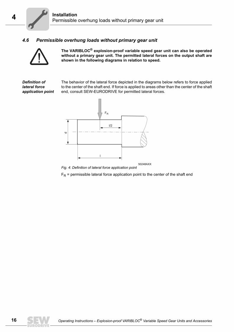
4 nstallationermissible overhung loads without primary gear unit
16
4.6 Permissible overhung loads without primary gear unit
Definition of lateral force application point
The behavior of the lateral force depicted in the diagrams below refers to force appliedto the center of the shaft end. If force is applied to areas other than the center of the shaftend, consult SEW-EURODRIVE for permitted lateral forces.
FR = permissible lateral force application point to the center of the shaft end
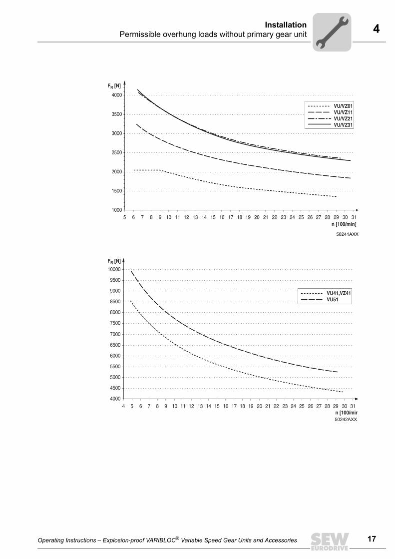
The VARIBLOC® explosion-proof variable speed gear unit can also be operatedwithout a primary gear unit. The permitted lateral forces on the output shaft areshown in the following diagrams in relation to speed.
50248AXXFig. 4: Definition of lateral force application point
FR
d
l
l/2
IP
Operating Instructions – Explosion-proof VARIBLOC® Variable Speed Gear Units and Accessories
4InstallationPermissible overhung loads without primary gear unit
50241AXX
50242AXX
1000
1500
2000
2500
3000
3500
4000
5n [100/min]
FR [N]
6 7 8 9 10 11 12 13 14 15 16 17 18 19 20 21 22 23 24 25 26 27 28 29 30 31
VU/VZ01VU/VZ11VU/VZ21VU/VZ31
4000
4500
5000
5500
6000
6500
7000
7500
8000
8500
9000
9500
10000
4 5 6 7 8 9 10 11 12 13 14 15 16 17 18 19 20 21 22 23 24 25 26 27 28 29 30 31
FR [N]
n [100/min
VU41,VZ41VU51
Operating Instructions – Explosion-proof VARIBLOC® Variable Speed Gear Units and Accessories
17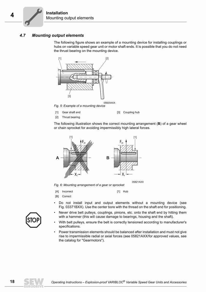
4 nstallationounting output elements
18
4.7 Mounting output elementsThe following figure shows an example of a mounting device for installing couplings orhubs on variable speed gear unit or motor shaft ends. It is possible that you do not needthe thrust bearing on the mounting device.
The following illustration shows the correct mounting arrangement (B) of a gear wheelor chain sprocket for avoiding impermissibly high lateral forces.
• Do not install input and output elements without a mounting device (seeFig. 03371BXX). Use the center bore with the thread on the shaft end for positioning.
• Power transmission elements should be balanced after installation and must not giverise to impermissible radial or axial forces (see 05821AXX/for approved values, seethe catalog for "Gearmotors").
05820AXXFig. 5: Example of a mounting device
[1] Gear shaft end [3] Coupling hub
[2] Thrust bearing
05821AXXFig. 6: Mounting arrangement of a gear or sprocket
[A] Incorrect [1] Hub
[B] Correct
[1][1]
• Never drive belt pulleys, couplings, pinions, etc. onto the shaft end by hitting themwith a hammer (this will cause damage to bearings, housing and the shaft).
• With belt pulleys, ensure the belt is correctly tensioned according to manufacturer'sspecifications.
IM
Operating Instructions – Explosion-proof VARIBLOC® Variable Speed Gear Units and Accessories
4InstallationMounting output elements
Mounting couplings
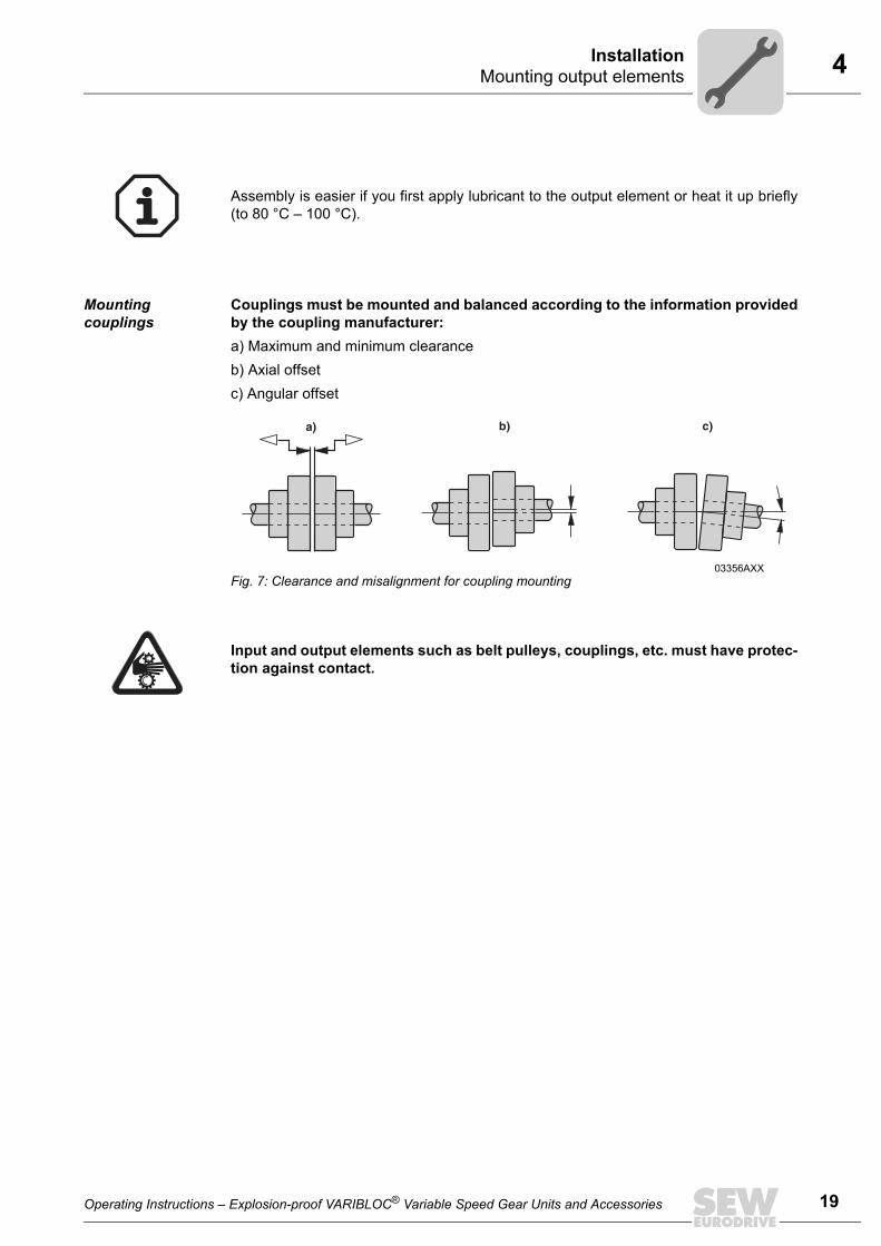
Couplings must be mounted and balanced according to the information providedby the coupling manufacturer:a) Maximum and minimum clearanceb) Axial offsetc) Angular offset
Assembly is easier if you first apply lubricant to the output element or heat it up briefly(to 80 °C – 100 °C).
03356AXXFig. 7: Clearance and misalignment for coupling mounting
a) b) c)
Input and output elements such as belt pulleys, couplings, etc. must have protec-tion against contact.
Operating Instructions – Explosion-proof VARIBLOC® Variable Speed Gear Units and Accessories
19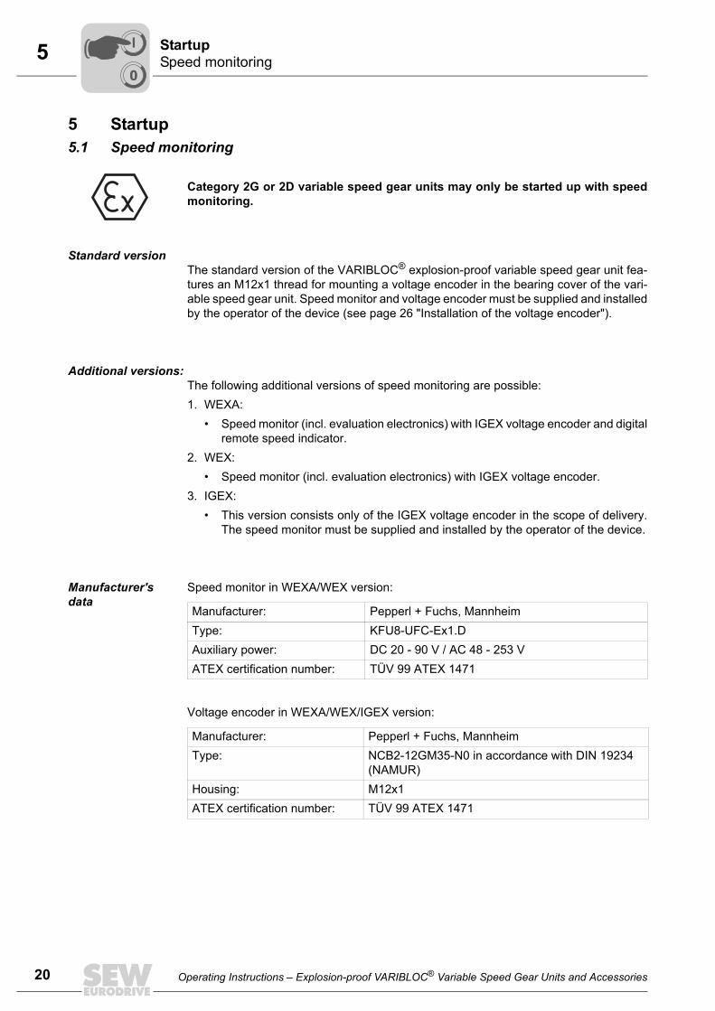
5 tartuppeed monitoring
20
5 Startup5.1 Speed monitoring
Standard versionThe standard version of the VARIBLOC® explosion-proof variable speed gear unit fea-tures an M12x1 thread for mounting a voltage encoder in the bearing cover of the vari-able speed gear unit. Speed monitor and voltage encoder must be supplied and installedby the operator of the device (see page 26 "Installation of the voltage encoder").
Additional versions:The following additional versions of speed monitoring are possible:1. WEXA:
• Speed monitor (incl. evaluation electronics) with IGEX voltage encoder and digitalremote speed indicator.
2. WEX:• Speed monitor (incl. evaluation electronics) with IGEX voltage encoder.
3. IGEX: • This version consists only of the IGEX voltage encoder in the scope of delivery.
The speed monitor must be supplied and installed by the operator of the device.
Manufacturer's data
Speed monitor in WEXA/WEX version:
Voltage encoder in WEXA/WEX/IGEX version:
Category 2G or 2D variable speed gear units may only be started up with speedmonitoring.
Manufacturer: Pepperl + Fuchs, MannheimType: KFU8-UFC-Ex1.DAuxiliary power: DC 20 - 90 V / AC 48 - 253 VATEX certification number: TÜV 99 ATEX 1471
Manufacturer: Pepperl + Fuchs, MannheimType: NCB2-12GM35-N0 in accordance with DIN 19234
(NAMUR)Housing: M12x1ATEX certification number: TÜV 99 ATEX 1471
SS
00
I
Operating Instructions – Explosion-proof VARIBLOC® Variable Speed Gear Units and Accessories
5StartupInstallation and adjustment of the WEXA/WEX speed monitor
5.2 Installation and adjustment of the WEXA/WEX speed monitor
1. Read the operating instructions of the speed monitor manufacturer before you beginwith the installation.
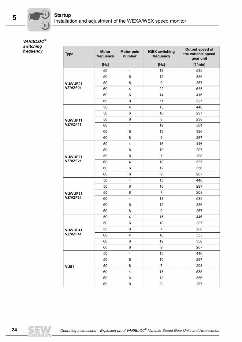
2. Perform the basic adjustment of the speed monitor in accordance with the operatinginstructions of the speed monitor manufacturer (see table "VARIBLOC® switchingfrequency" on page 24).Setting must be carried out in a way that the drive switches off when the frequencyor speed drops below the limit values specified in the above table. The sensor builtin the variable speed gear unit generates two pulses per revolution of the variablespeed gear shaft. If the switching speed of the variable speed gear unit is not met, the drive motor mustbe immediately disconnected from its supply voltage.The cause of the problem must be eliminated and the operation of the variable speedgear unit stopped for at least 15 minutes before restarting the variable speed gearunit. If incorrect operation by the operating personnel cannot be ruled out, thisinterval should be triggered by an automatic restart lockout.If vibrations or increased operating noises are noticeable after restarting the variablespeed gear unit, the wide V-belt was damaged during the blocking and must bereplaced (see Sec. "Inspection/maintenance" Replacing wide V-belt).
The speed monitor must be located outside the potentially explosive atmosphere.
All installation and setting notes given below refer to the speed monitor or voltageencoder in WEXA/WEX version.
If other speed monitors in WEXA/WEX version are used, they must be installedand started up according to the manufacturer’s documentation. The section"Installation and adjustment of other speed monitors" (see the following page)contains information on determining the switching speed or switching frequencyfor this particular case.
Operating Instructions – Explosion-proof VARIBLOC® Variable Speed Gear Units and Accessories
00
I
21
5 tartupnstallation and adjustment of the WEXA/WEX speed monitor
22
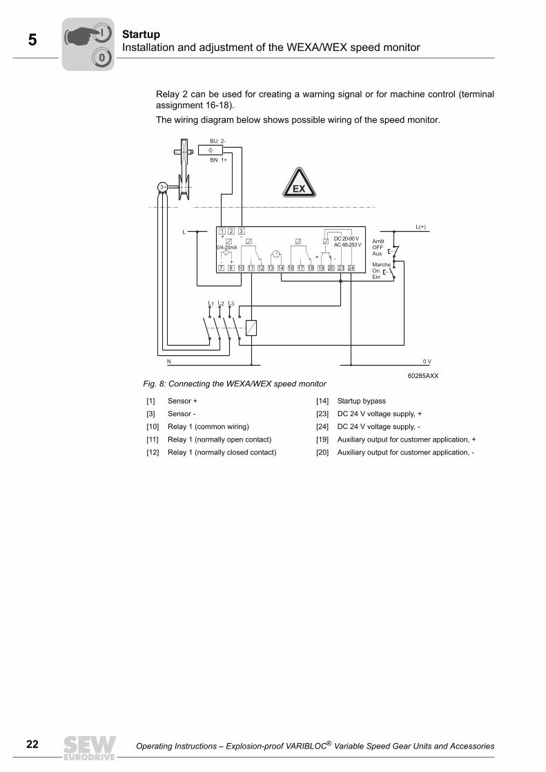
Relay 2 can be used for creating a warning signal or for machine control (terminalassignment 16-18).The wiring diagram below shows possible wiring of the speed monitor.
60285AXXFig. 8: Connecting the WEXA/WEX speed monitor
[1] Sensor + [14] Startup bypass
[3] Sensor - [23] DC 24 V voltage supply, +
[10] Relay 1 (common wiring) [24] DC 24 V voltage supply, -
[11] Relay 1 (normally open contact) [19] Auxiliary output for customer application, +
[12] Relay 1 (normally closed contact) [20] Auxiliary output for customer application, -
BU 2-
3~
BN 1+
MarcheOnEin
ArrêtOFFAus
L1 L2 L3
0 VN
L(+)L 1
7 8 11 12 13 14 16 17 1810
2 3+
++
-
--
19 20 23 24
DC 20-90 VAC 48-253 V
0/4-20mA
EX
SI
00
I
Operating Instructions – Explosion-proof VARIBLOC® Variable Speed Gear Units and Accessories
5StartupInstallation and adjustment of the WEXA/WEX speed monitor
Front side of the speed monitor
Front side of the speed monitor:
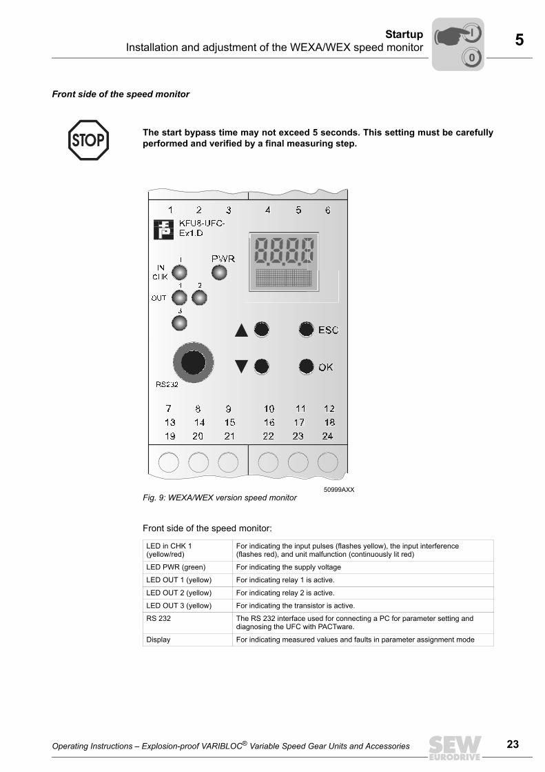
The start bypass time may not exceed 5 seconds. This setting must be carefullyperformed and verified by a final measuring step.
50999AXXFig. 9: WEXA/WEX version speed monitor
LED in CHK 1 (yellow/red)
For indicating the input pulses (flashes yellow), the input interference (flashes red), and unit malfunction (continuously lit red)
LED PWR (green) For indicating the supply voltage
LED OUT 1 (yellow) For indicating relay 1 is active.
LED OUT 2 (yellow) For indicating relay 2 is active.
LED OUT 3 (yellow) For indicating the transistor is active.
RS 232 The RS 232 interface used for connecting a PC for parameter setting and diagnosing the UFC with PACTware.
Display For indicating measured values and faults in parameter assignment mode
Operating Instructions – Explosion-proof VARIBLOC® Variable Speed Gear Units and Accessories
00
I
23
5 tartupnstallation and adjustment of the WEXA/WEX speed monitor
24
VARIBLOC® switching frequency
Type Motor frequency
Motor pole number
IGEX switching frequency
Output speed of the variable speed
gear unit[Hz] [Hz] [1/min]
VU/VUF01VZ/VZF01
50 4 18 535
50 6 12 356
50 8 9 267
60 4 22 635
60 6 14 416
60 8 11 327
VU/VUF11 VZ/VZF11
50 4 15 446
50 6 10 297
50 8 8 238
60 4 19 564
60 6 13 386
60 8 9 267
VU/VUF21VZ/VZF21
50 4 15 446
50 6 10 297
50 8 7 208
60 4 18 535
60 6 12 356
60 8 9 267
VU/VUF31VZ/VZF31
50 4 15 446
50 6 10 297
50 8 7 208
60 4 18 535
60 6 12 356
60 8 9 267
VU/VUF41VZ/VZF41
50 4 15 446
50 6 10 297
50 8 7 208
60 4 18 535
60 6 12 356
60 8 9 267
VU51
50 4 15 446
50 6 10 297
50 8 7 208
60 4 18 535
60 6 12 356
60 8 9 267
SI
00
I
Operating Instructions – Explosion-proof VARIBLOC® Variable Speed Gear Units and Accessories
5StartupInstallation and adjustment of the WEXA/WEX speed monitor
Installation and adjustment of other speed monitors
If other speed monitors are used, they must feature an intrinsically safe sensor input(identification color: blue) for evaluating sensors in accordance with DIN 19234(NAMUR) and be approved for use of this sensor in potentially explosive atmospheres.
The voltage encoder (sensor) generally features a blue connection lead and must con-form to DIN 19234 (NAMUR). The corresponding inspection number may be attachedto the voltage encoder or the connection cable.
If the switching speed of the variable speed gear unit is not met, the drive motormust be immediately disconnected from its supply voltage.The cause of the problem must be eliminated and the operation of the variablespeed gear unit stopped for at least 15 minutes before restarting the variablespeed gear unit. If incorrect operation by the operating personnel cannot be ruledout, this interval should be triggered by an automatic restart lockout.If vibrations or increased operating noises are noticeable after restarting the vari-able speed gear unit, the wide V-belt was damaged during the blocking and mustbe replaced (see Sec. "Inspection/maintenance" Replacing wide V-belt).
Operating Instructions – Explosion-proof VARIBLOC® Variable Speed Gear Units and Accessories
00
I
25
5 tartupnstallation of the voltage encoder
26
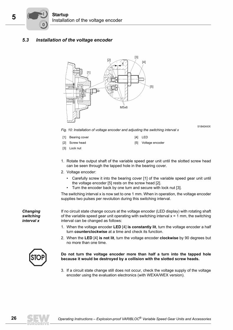
5.3 Installation of the voltage encoder
1. Rotate the output shaft of the variable speed gear unit until the slotted screw headcan be seen through the tapped hole in the bearing cover.
2. Voltage encoder:• Carefully screw it into the bearing cover [1] of the variable speed gear unit until
the voltage encoder [5] rests on the screw head [2].• Turn the encoder back by one turn and secure with lock nut [3].
The switching interval x is now set to one 1 mm. When in operation, the voltage encodersupplies two pulses per revolution during this switching interval.
Changing switching interval x
If no circuit state change occurs at the voltage encoder (LED display) with rotating shaftof the variable speed gear unit operating with switching interval x = 1 mm, the switchinginterval can be changed as follows: 1. When the voltage encoder LED [4] is constantly lit, turn the voltage encoder a half
turn counterclockwise at a time and check its function.2. When the LED [4] is not lit, turn the voltage encoder clockwise by 90 degrees but
no more than one time.
3. If a circuit state change still does not occur, check the voltage supply of the voltageencoder using the evaluation electronics (with WEXA/WEX version).
51840AXXFig. 10: Installation of voltage encoder and adjusting the switching interval x
[1] Bearing cover [4] LED
[2] Screw head [5] Voltage encoder
[3] Lock nut
[1]
[2]
M5x6
[3]
[4]
[5]
X
Do not turn the voltage encoder more than half a turn into the tapped holebecause it would be destroyed by a collision with the slotted screw heads.
SI
00
I
Operating Instructions – Explosion-proof VARIBLOC® Variable Speed Gear Units and Accessories
5StartupMounting right-angled tachometer TW, axial tachometer TA
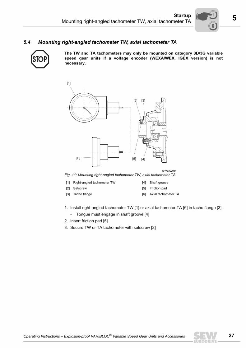
5.4 Mounting right-angled tachometer TW, axial tachometer TA
1. Install right-angled tachometer TW [1] or axial tachometer TA [6] in tacho flange [3]:• Tongue must engage in shaft groove [4]
2. Insert friction pad [5]3. Secure TW or TA tachometer with setscrew [2]
The TW and TA tachometers may only be mounted on category 3D/3G variablespeed gear units if a voltage encoder (WEXA/WEX, IGEX version) is notnecessary.
60248AXXFig. 11: Mounting right-angled tachometer TW, axial tachometer TA
[1] Right-angled tachometer TW [4] Shaft groove
[2] Setscrew [5] Friction pad
[3] Tacho flange [6] Axial tachometer TA
[1]
[3][2]
[4][5][6]
Operating Instructions – Explosion-proof VARIBLOC® Variable Speed Gear Units and Accessories
00
I
27
5 tartupigital remote speed indicator
28
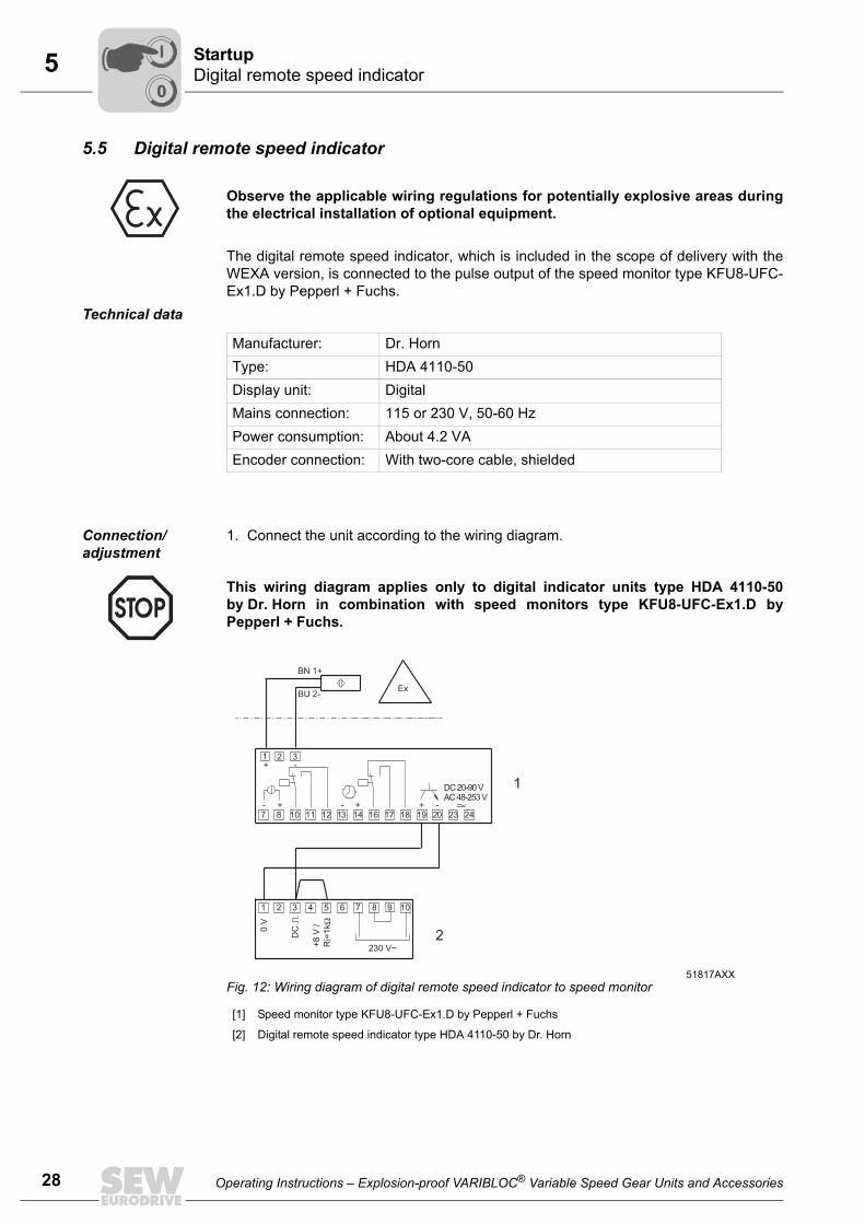
5.5 Digital remote speed indicator
The digital remote speed indicator, which is included in the scope of delivery with theWEXA version, is connected to the pulse output of the speed monitor type KFU8-UFC-Ex1.D by Pepperl + Fuchs.
Technical data
Connection/ adjustment
1. Connect the unit according to the wiring diagram.
Observe the applicable wiring regulations for potentially explosive areas duringthe electrical installation of optional equipment.
Manufacturer: Dr. HornType: HDA 4110-50Display unit: DigitalMains connection: 115 or 230 V, 50-60 HzPower consumption: About 4.2 VAEncoder connection: With two-core cable, shielded
This wiring diagram applies only to digital indicator units type HDA 4110-50by Dr. Horn in combination with speed monitors type KFU8-UFC-Ex1.D byPepperl + Fuchs.
51817AXXFig. 12: Wiring diagram of digital remote speed indicator to speed monitor
[1] Speed monitor type KFU8-UFC-Ex1.D by Pepperl + Fuchs
[2] Digital remote speed indicator type HDA 4110-50 by Dr. Horn
BU 2-
BN 1+
1
7
1
0V
DC
+8
V/
Ri=
1kΩ
8
2
11
4 5
230 V~
6 7 8 9
12 13 14 16 17 18
10
10
3
2 3+
+ + +
-
- - -
Ex
19 20 23 24
DC 20-90 VAC 48-253 V
1
2
SD
00
I
Operating Instructions – Explosion-proof VARIBLOC® Variable Speed Gear Units and Accessories
5StartupDigital remote speed indicator
2. Note the jumpers:• Between terminals 3 and 5• Between terminals 8 and 9 for AC 230 V auxiliary power
3. Adjust measuring interval (see the following figure and Sec. "Calculation examplesfor digital remote speed indicator" on page 31).• Calculation using a formula• Data according to table "Reference data of digital remote speed indicator"
page 314. Adjust input sensitivity (see next page):
• Turn "input sensitivity" potentiometer clockwise until the pulse indicator lightlights up.
With auxiliary power of AC 115 V, the wiring of terminals 7, 8, 9, and 10 must bechanged according to the manufacturer's documentation.
Operating Instructions – Explosion-proof VARIBLOC® Variable Speed Gear Units and Accessories
00
I
29
5 tartupigital remote speed indicator
30
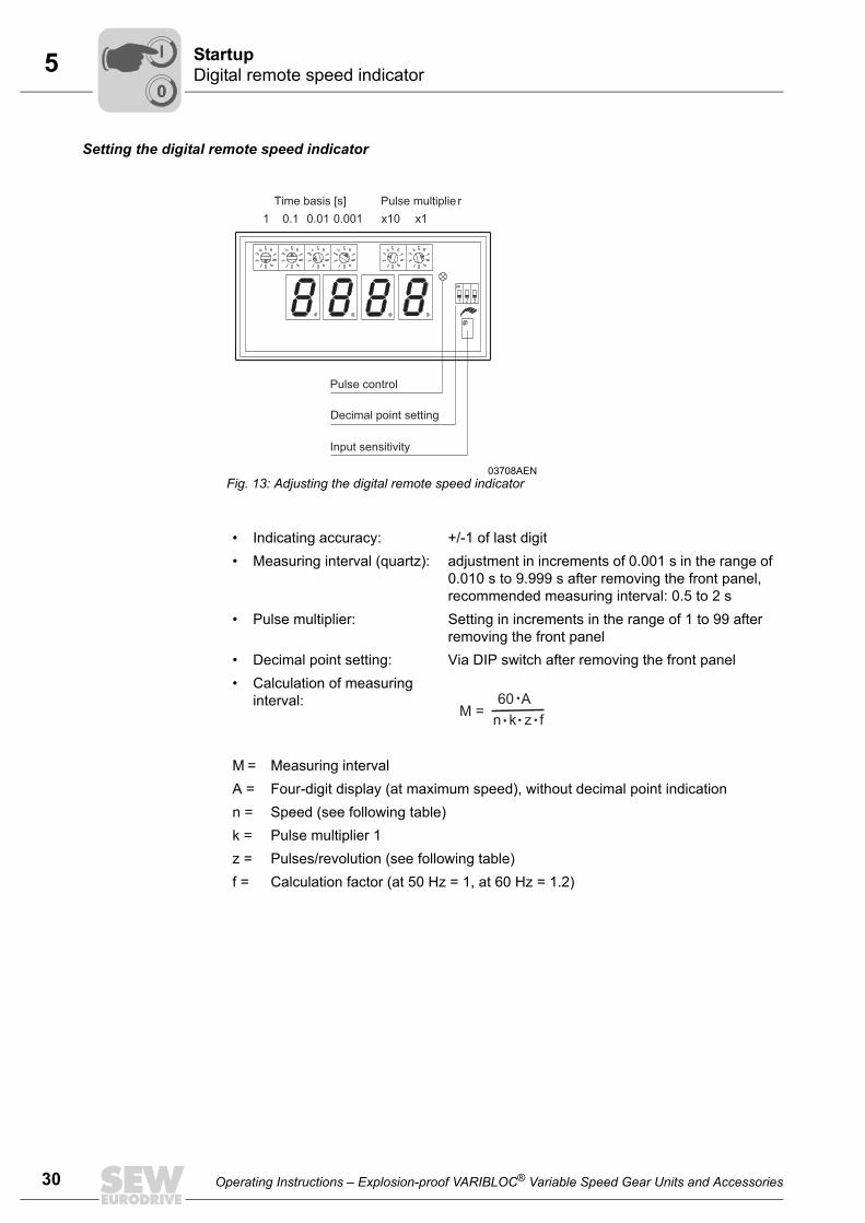
Setting the digital remote speed indicator
03708AENFig. 13: Adjusting the digital remote speed indicator
• Indicating accuracy: +/-1 of last digit• Measuring interval (quartz): adjustment in increments of 0.001 s in the range of
0.010 s to 9.999 s after removing the front panel, recommended measuring interval: 0.5 to 2 s
• Pulse multiplier: Setting in increments in the range of 1 to 99 after removing the front panel
• Decimal point setting: Via DIP switch after removing the front panel• Calculation of measuring
interval:
M = Measuring intervalA = Four-digit display (at maximum speed), without decimal point indicationn = Speed (see following table)k = Pulse multiplier 1z = Pulses/revolution (see following table)f = Calculation factor (at 50 Hz = 1, at 60 Hz = 1.2)
1 0.1 x10 x10.01 0.001
Time basis [s] Pulse multiplie r
Pulse control
Decimal point setting
Input sensitivity
SD
00
I
Operating Instructions – Explosion-proof VARIBLOC® Variable Speed Gear Units and Accessories
5StartupDigital remote speed indicator
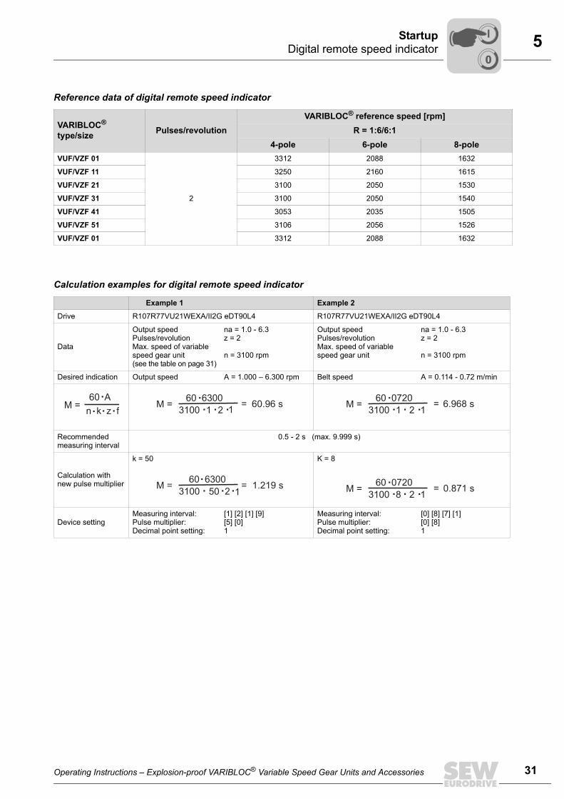
Reference data of digital remote speed indicator
Calculation examples for digital remote speed indicator
VARIBLOC®
type/size Pulses/revolutionVARIBLOC® reference speed [rpm]
R = 1:6/6:14-pole 6-pole 8-pole
VUF/VZF 01
2
3312 2088 1632
VUF/VZF 11 3250 2160 1615
VUF/VZF 21 3100 2050 1530
VUF/VZF 31 3100 2050 1540
VUF/VZF 41 3053 2035 1505
VUF/VZF 51 3106 2056 1526
VUF/VZF 01 3312 2088 1632
Example 1 Example 2
Drive R107R77VU21WEXA/II2G eDT90L4 R107R77VU21WEXA/II2G eDT90L4
Data
Output speedPulses/revolutionMax. speed of variable speed gear unit (see the table on page 31)
na = 1.0 - 6.3z = 2
n = 3100 rpm
Output speedPulses/revolutionMax. speed of variable speed gear unit
na = 1.0 - 6.3z = 2
n = 3100 rpm
Desired indication Output speed A = 1.000 – 6.300 rpm Belt speed A = 0.114 - 0.72 m/min
Recommended measuring interval
0.5 - 2 s (max. 9.999 s)
Calculation with new pulse multiplier
k = 50 K = 8
Device settingMeasuring interval:Pulse multiplier:Decimal point setting:
[1] [2] [1] [9][5] [0]1
Measuring interval:Pulse multiplier:Decimal point setting:
[0] [8] [7] [1][0] [8]1
60.96 s 6.968 s
1.219 s 0.871 s
Operating Instructions – Explosion-proof VARIBLOC® Variable Speed Gear Units and Accessories
00
I
31
6 nspection and Maintenanceefore you begin
32
6 Inspection and Maintenance
6.1 Before you beginRequired tools/resources
• Set of wrenches• Hammer• Drift or punch drift• Snap ring, mounting press
Strict adherence to the inspection and maintenance intervals is absolutely neces-sary to ensure safe working conditions and explosion protection.
• Strictly observe the safety notes in the individual sections.• All maintenance work must be carefully performed by qualified personnel.• Work on the gear unit only when the machine is not in use. Prevent the drive
unit from unintentionally starting up (for example, by locking the keyswitch orremoving the fuses from the power supply). Place an information sign by theon-switch to warn that the gear unit is being worked on.
• Use only genuine spare parts from the relevant valid spare parts list; other-wise, the explosion rating of the variable speed drive becomes void.
IB
Operating Instructions – Explosion-proof VARIBLOC® Variable Speed Gear Units and Accessories
6Inspection and MaintenanceInspection and maintenance intervals
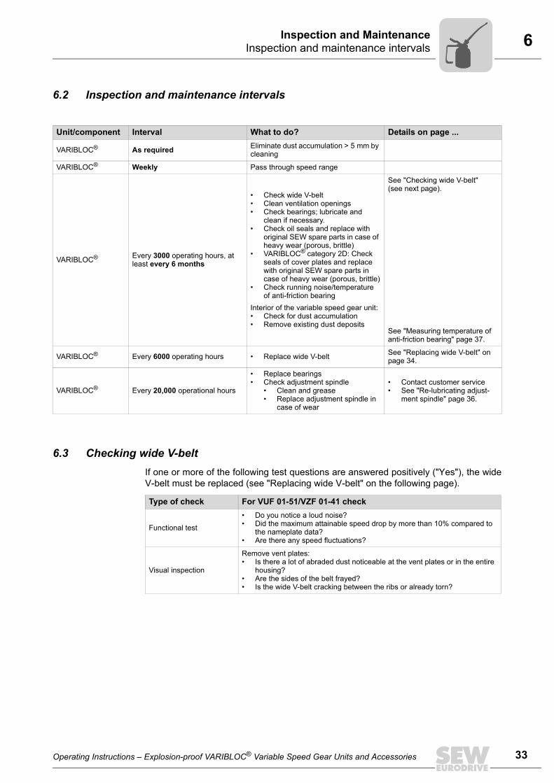
6.2 Inspection and maintenance intervals
6.3 Checking wide V-beltIf one or more of the following test questions are answered positively ("Yes"), the wideV-belt must be replaced (see "Replacing wide V-belt" on the following page).
Unit/component Interval What to do? Details on page ...
VARIBLOC® As required Eliminate dust accumulation > 5 mm by cleaning
VARIBLOC® Weekly Pass through speed range
VARIBLOC® Every 3000 operating hours, at least every 6 months
• Check wide V-belt• Clean ventilation openings• Check bearings; lubricate and
clean if necessary.• Check oil seals and replace with
original SEW spare parts in case of heavy wear (porous, brittle)
• VARIBLOC® category 2D: Check seals of cover plates and replace with original SEW spare parts in case of heavy wear (porous, brittle)
• Check running noise/temperature of anti-friction bearing
Interior of the variable speed gear unit:• Check for dust accumulation• Remove existing dust deposits
See "Checking wide V-belt" (see next page).
See "Measuring temperature of anti-friction bearing" page 37.
VARIBLOC® Every 6000 operating hours • Replace wide V-belt See "Replacing wide V-belt" on page 34.
VARIBLOC® Every 20,000 operational hours
• Replace bearings• Check adjustment spindle
• Clean and grease• Replace adjustment spindle in
case of wear
• Contact customer service• See "Re-lubricating adjust-
ment spindle" page 36.
Type of check For VUF 01-51/VZF 01-41 check
Functional test
• Do you notice a loud noise?• Did the maximum attainable speed drop by more than 10% compared to
the nameplate data?• Are there any speed fluctuations?
Visual inspection
Remove vent plates:• Is there a lot of abraded dust noticeable at the vent plates or in the entire
housing?• Are the sides of the belt frayed?• Is the wide V-belt cracking between the ribs or already torn?
Operating Instructions – Explosion-proof VARIBLOC® Variable Speed Gear Units and Accessories
33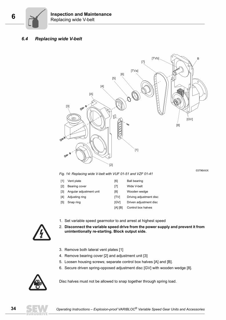
6 nspection and Maintenanceeplacing wide V-belt
34
6.4 Replacing wide V-belt
1. Set variable speed gearmotor to and arrest at highest speed2. Disconnect the variable speed drive from the power supply and prevent it from
unintentionally re-starting. Block output side.
3. Remove both lateral vent plates [1]4. Remove bearing cover [2] and adjustment unit [3]5. Loosen housing screws; separate control box halves [A] and [B].6. Secure driven spring-opposed adjustment disc [GV] with wooden wedge [8].
03796AXXFig. 14: Replacing wide V-belt with VUF 01-51 and VZF 01-41
[1] Vent plate [6] Ball bearing
[2] Bearing cover [7] Wide V-belt
[3] Angular adjustment unit [8] Wooden wedge
[4] Adjusting ring [TV] Driving adjustment disc
[5] Snap ring [GV] Driven adjustment disc
[A] [B] Control box halves
[1]
[2]
[3]
[A]
[4]
[5]
[6]
[7]B
[GV]
[8]
[TVa]
[TVb]
Disc halves must not be allowed to snap together through spring load.
IR
Operating Instructions – Explosion-proof VARIBLOC® Variable Speed Gear Units and Accessories
6Inspection and MaintenanceReplacing wide V-belt
7. Remove:• Adjusting ring [4] (for front adjustment), snap ring [5], driving adjustment disc
halves [TVa]8. Remove old wide V-belt [7] and insert new wide V-belt.9. Install:
• Driving adjustment half [TVa], ball bearing [6], snap ring [5], adjusting ring [4]10.Remove wooden wedge11.Screw control box halves [A] and [B] together12.Mount adjustment unit and bearing cover [2]13.Attach vent plates [1]14.Tighten wide V-belt
• Turn positioning spindle clockwise using adjustment unit [3] until resistance isnoticeable
15.Check torsional play at output shaft• Correct: Minor torsional play is noticeable
16.Remove blocking from output side (see point 2)17.Switch on gearmotor18.Slowly pass through the speed range
• Correct: Drive runs smoothly and evenly
Operating Instructions – Explosion-proof VARIBLOC® Variable Speed Gear Units and Accessories
35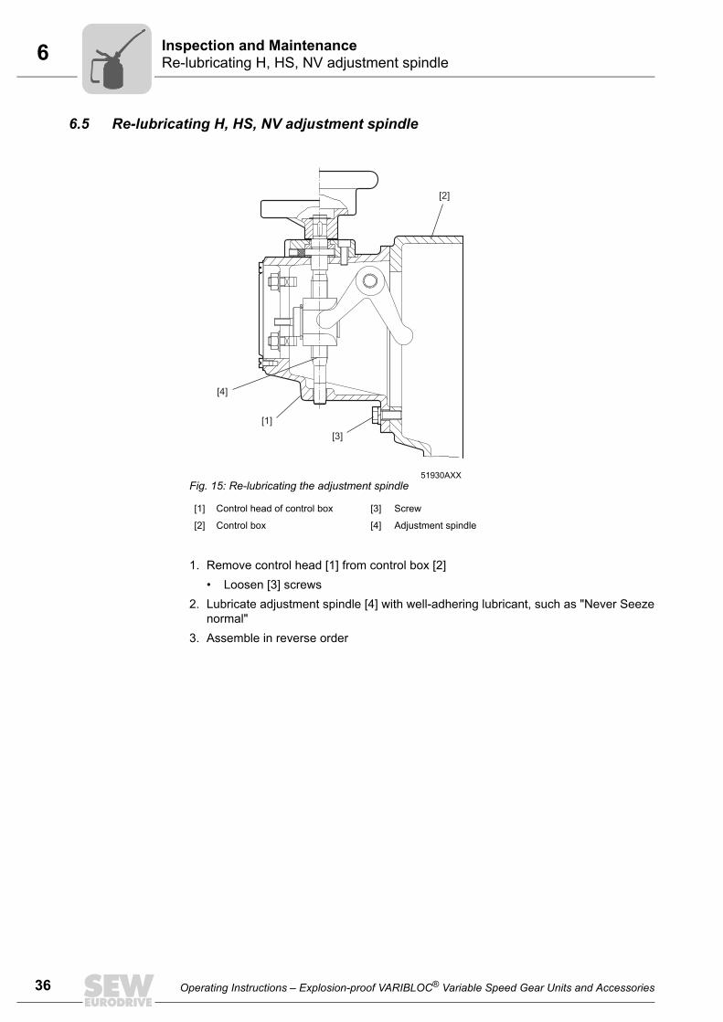
6 nspection and Maintenancee-lubricating H, HS, NV adjustment spindle
36
6.5 Re-lubricating H, HS, NV adjustment spindle
1. Remove control head [1] from control box [2]• Loosen [3] screws
2. Lubricate adjustment spindle [4] with well-adhering lubricant, such as "Never Seezenormal"
3. Assemble in reverse order
51930AXXFig. 15: Re-lubricating the adjustment spindle
[1] Control head of control box [3] Screw
[2] Control box [4] Adjustment spindle
[1]
[2]
[3]
[4]
IR
Operating Instructions – Explosion-proof VARIBLOC® Variable Speed Gear Units and Accessories
6Inspection and MaintenanceMeasuring the temperature of the anti-friction bearing
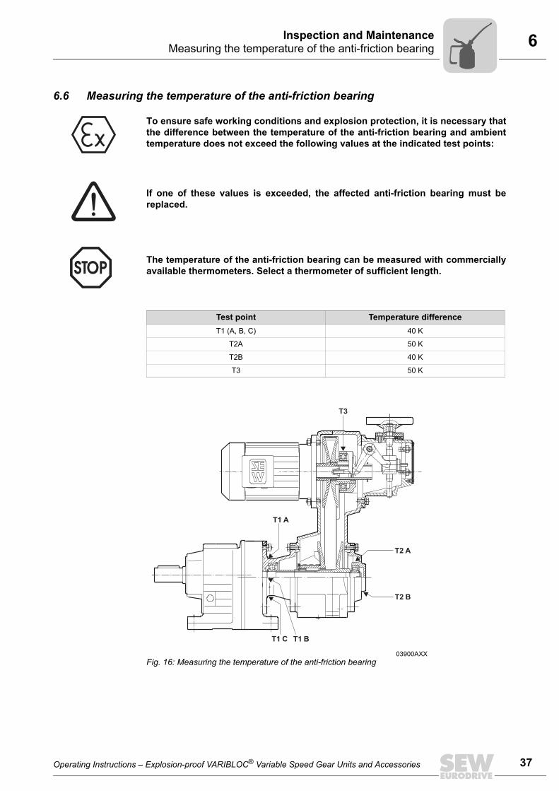
6.6 Measuring the temperature of the anti-friction bearing
To ensure safe working conditions and explosion protection, it is necessary thatthe difference between the temperature of the anti-friction bearing and ambienttemperature does not exceed the following values at the indicated test points:
If one of these values is exceeded, the affected anti-friction bearing must bereplaced.
The temperature of the anti-friction bearing can be measured with commerciallyavailable thermometers. Select a thermometer of sufficient length.
Test point Temperature differenceT1 (A, B, C) 40 K
T2A 50 K
T2B 40 K
T3 50 K
03900AXXFig. 16: Measuring the temperature of the anti-friction bearing
T2 A
T3
T2 B
T1 BT1 C
T1 A
Operating Instructions – Explosion-proof VARIBLOC® Variable Speed Gear Units and Accessories
37
6 nspection and Maintenanceeasuring the temperature of the anti-friction bearing
38
1. The bearing temperature of bearing 1 can be measured during operationdepending on mounting position and accessibility at one of the test points T1A, T1Bor T1C.
2. The bearing temperature of bearing 2 and bearing 3 may only be measured duringstandstill at test points T2A and T3.
Measuring the anti-friction bearing temperature of bearing 2 (T2A, T2B):
If a design-specific protective cover is attached to bearing 2, it must first be removed.1. With ventilated variable speed gear units, test point T2A is located about 15 to
20 mm behind the vent slot.2. For non-ventilated variable speed gear units, test point T2A is not accessible. In this
case, the temperature of the anti-friction bearing can be measured at test point T2Bduring operation.
Measuring the anti-friction bearing temperature of bearing 3 (T3):
1. Change the setting range until test point T3 is accessible.2. Shut down the variable speed gear unit, and prevent it from re-starting unintentionally. 3. Remove the vent plate (see Fig. Changing wide V-belt, pos. 1).4. Measure the temperature of the anti-friction bearing at test point T3.5. Re-adjust the setting range.
Limiting the speed range for versions NV, H, HS
The limit speeds nmin and nmax are factory set and may not be changed.If the maximum speed should drop by more than 10% due to wear of the wide V-belt, the wide V-belt must be replaced with an original SEW spare part.
IM
Operating Instructions – Explosion-proof VARIBLOC® Variable Speed Gear Units and Accessories
6Inspection and MaintenanceCompleting the inspection/maintenance process
6.7 Completing the inspection/maintenance process• Pay attention that you correctly reassemble the variable speed drive and care-
fully seal all apertures after maintenance and repair work with variable speeddrives category 2D. In this case, explosion protection is particularly dependenton the IP enclosure.
• Ensure that the top ventilation openings of the bearing cover with the variablespeed drives of categories 2G, 3G, and 3D are protected by a cowl in the areaof the bearing cover to prevent objects from entering.
• If the mounting position requires that the control box be mounted horizontally,the vent plate located on the top must be covered by the cover plate that isincluded in the scope of delivery.
• For variable speed drives category 2D, all ventilation openings must be closeddust-tight.
• Perform safety and function checks.
Operating Instructions – Explosion-proof VARIBLOC® Variable Speed Gear Units and Accessories
39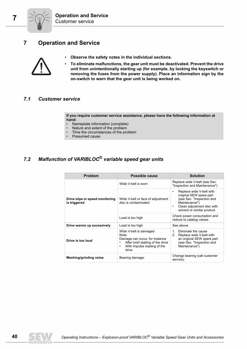
7 peration and Serviceustomer service
40
7 Operation and Service
7.1 Customer service
7.2 Malfunction of VARIBLOC® variable speed gear units
• Observe the safety notes in the individual sections.• To eliminate malfunctions, the gear unit must be deactivated. Prevent the drive
unit from unintentionally starting up (for example, by locking the keyswitch orremoving the fuses from the power supply). Place an information sign by theon-switch to warn that the gear unit is being worked on.
If you require customer service assistance, please have the following information at hand:• Nameplate information (complete)• Nature and extent of the problem• Time the circumstances of the problem• Presumed cause
Problem Possible cause Solution
Drive slips or speed monitoring is triggered
Wide V-belt is worn Replace wide V-belt (see Sec. "Inspection and Maintenance")
Wide V-belt or face of adjustment disc is contaminated
• Replace wide V-belt with original SEW spare part (see Sec. "Inspection andMaintenance")
• Clean adjustment disc with solvent or similar product
Load is too high Check power consumption and reduce to catalog values
Drive warms up excessively Load is too high See above
Drive is too loud
Wide V-belt is damagedNote:Damage can occur, for instance• After brief stalling of the drive• With impulse loading of the
drive
1. Eliminate the cause2. Replace wide V-belt with
an original SEW spare part (see Sec. "Inspection and Maintenance")
Meshing/grinding noise Bearing damage: Change bearing (call customer service)
OC
Operating Instructions – Explosion-proof VARIBLOC® Variable Speed Gear Units and Accessories
7Operation and ServiceWEXA/WEX speed monitoring malfunctions
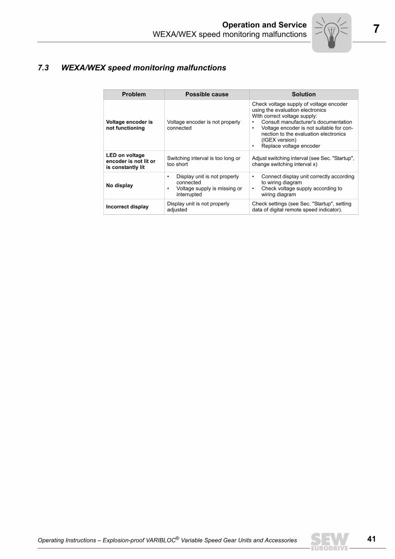
7.3 WEXA/WEX speed monitoring malfunctions
Problem Possible cause Solution
Voltage encoder is not functioning
Voltage encoder is not properly connected
Check voltage supply of voltage encoder using the evaluation electronicsWith correct voltage supply:• Consult manufacturer's documentation • Voltage encoder is not suitable for con-
nection to the evaluation electronics (IGEX version)
• Replace voltage encoder
LED on voltage encoder is not lit or is constantly lit
Switching interval is too long or too short
Adjust switching interval (see Sec. "Startup", change switching interval x)
No display• Display unit is not properly
connected• Voltage supply is missing or
interrupted
• Connect display unit correctly according to wiring diagram
• Check voltage supply according to wiring diagram
Incorrect display Display unit is not properly adjusted
Check settings (see Sec. "Startup", setting data of digital remote speed indicator).
Operating Instructions – Explosion-proof VARIBLOC® Variable Speed Gear Units and Accessories
41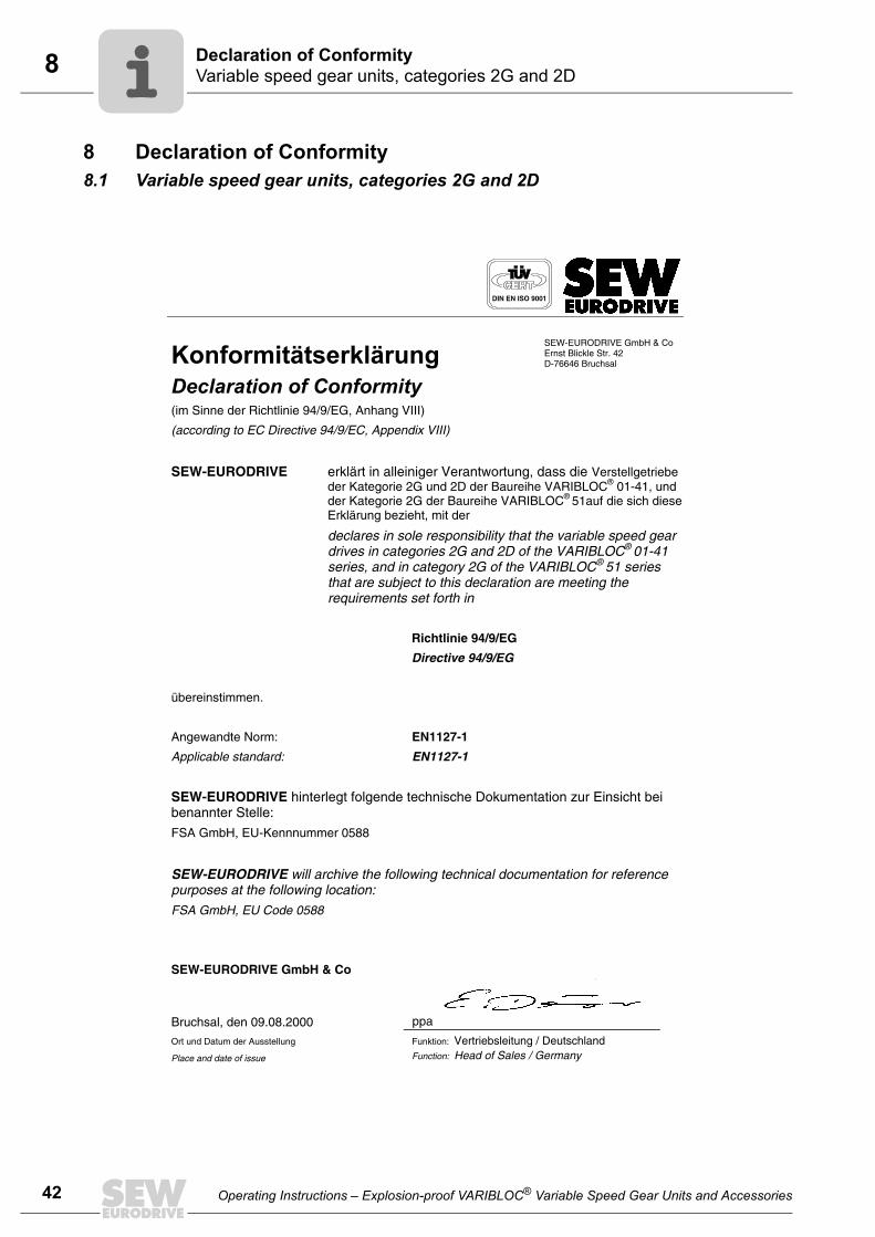
8 eclaration of Conformityariable speed gear units, categories 2G and 2D
42
8 Declaration of Conformity8.1 Variable speed gear units, categories 2G and 2D
DIN EN ISO 9001
(im Sinne der Richtlinie 94/9/EG, Anhang VIII)
(according to EC Directive 94/9/EC, Appendix VIII)
SEW-EURODRIVE GmbH & Co Ernst Blickle Str. 42 D-76646 Bruchsal
SEW-EURODRIVE erklärt in alleiniger Verantwortung, dass die Verstellgetriebeder Kategorie 2G und 2D der Baureihe VARIBLOC® 01-41, und der Kategorie 2G der Baureihe VARIBLOC® 51auf die sich diese Erklärung bezieht, mit der
declares in sole responsibility that the variable speed gear drives in categories 2G and 2D of the VARIBLOC® 01-41series, and in category 2G of the VARIBLOC® 51 series that are subject to this declaration are meeting the requirements set forth in
Richtlinie 94/9/EG
Directive 94/9/EG
übereinstimmen.
Angewandte Norm: EN1127-1
Applicable standard: EN1127-1
SEW-EURODRIVE hinterlegt folgende technische Dokumentation zur Einsicht bei benannter Stelle:
FSA GmbH, EU-Kennnummer 0588
SEW-EURODRIVE will archive the following technical documentation for reference purposes at the following location: FSA GmbH, EU Code 0588
SEW-EURODRIVE GmbH & Co
Bruchsal, den 09.08.2000 ppa
Ort und Datum der Ausstellung
Place and date of issue
Funktion: Vertriebsleitung / DeutschlandFunction: Head of Sales / Germany
DV
Operating Instructions – Explosion-proof VARIBLOC® Variable Speed Gear Units and Accessories
8Declaration of ConformityVariable speed gear units, categories 3G and 3D
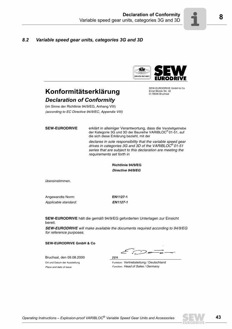
8.2 Variable speed gear units, categories 3G and 3D
DIN EN ISO 9001
(im Sinne der Richtlinie 94/9/EG, Anhang VIII)
(according to EC Directive 94/9/EC, Appendix VIII)
SEW-EURODRIVE GmbH & Co Ernst Blickle Str. 42 D-76646 Bruchsal
SEW-EURODRIVE erklärt in alleiniger Verantwortung, dass die Verstellgetriebeder Kategorie 3G und 3D der Baureihe VARIBLOC® 01-51, auf die sich diese Erklärung bezieht, mit der
declares in sole responsibility that the variable speed gear drives in categories 3G and 3D of the VARIBLOC® 01-51series that are subject to this declaration are meeting the requirements set forth in
Richtlinie 94/9/EG
Directive 94/9/EG
übereinstimmen.
Angewandte Norm: EN1127-1
Applicable standard: EN1127-1
SEW-EURODRIVE hält die gemäß 94/9/EG geforderten Unterlagen zur Einsicht bereit.
SEW-EURODRIVE will make available the documents required according to 94/9/EG for reference purposes.
SEW-EURODRIVE GmbH & Co
Bruchsal, den 09.08.2000 ppa
Ort und Datum der Ausstellung
Place and date of issue
Funktion: Vertriebsleitung / DeutschlandFunction: Head of Sales / Germany
Operating Instructions – Explosion-proof VARIBLOC® Variable Speed Gear Units and Accessories
43
9
44 Operating Instructions – Explosion-proof VARIBLOC® Variable Speed Gear Units and Accessories
Index
9 IndexAAdjustment spindle ..............................................36Anti-friction bearing greases ...............................14
DDesignated use .....................................................4Disposal ................................................................5
IImportant information ............................................4Inspection and maintenance ...............................32Installation ...........................................................14Installation tolerances .........................................15
MMaintenance intervals .........................................33Malfunction of VARIBLOC® variable speed gear units ............................................................40Mounting option ..................................................11Mounting output elements ...................................18
NNameplate ...........................................................10
OOptional equipment malfunction .........................41
PPermissible overhung loads without primary gear unit ..............................................................16
RRemote speed indicator ..................................... 28Right-angled tachometer TW, axial tachometer TA ........................................... 27
SSafety notes ......................................................... 7Speed monitoring ............................................... 20Startup ............................................................... 20
TTemperature of the anti-friction bearing ............. 37
UUnit design ........................................................... 8Unit designation ................................................... 9
VVARIBLOC® switching frequency ...................... 24Voltage encoder ................................................. 26
WWEXA/WEX speed monitor ............................... 21Wide V-belt ........................................................ 34
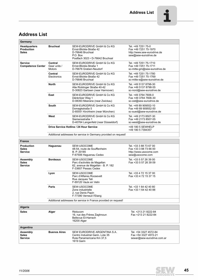
Address List
Address ListGermany
HeadquartersProductionSales
Bruchsal SEW-EURODRIVE GmbH & Co KGErnst-Blickle-Straße 42 D-76646 BruchsalP.O. BoxPostfach 3023 • D-76642 Bruchsal
Tel. +49 7251 75-0Fax +49 7251 75-1970http://[email protected]
Service Competence Center
CentralGear units / Motors
SEW-EURODRIVE GmbH & Co KGErnst-Blickle-Straße 1 D-76676 Graben-Neudorf
Tel. +49 7251 75-1710Fax +49 7251 [email protected]
CentralElectronics
SEW-EURODRIVE GmbH & Co KGErnst-Blickle-Straße 42 D-76646 Bruchsal
Tel. +49 7251 75-1780Fax +49 7251 [email protected]
North SEW-EURODRIVE GmbH & Co KGAlte Ricklinger Straße 40-42 D-30823 Garbsen (near Hannover)
Tel. +49 5137 8798-30Fax +49 5137 [email protected]
East SEW-EURODRIVE GmbH & Co KGDänkritzer Weg 1D-08393 Meerane (near Zwickau)
Tel. +49 3764 7606-0Fax +49 3764 [email protected]
South SEW-EURODRIVE GmbH & Co KGDomagkstraße 5D-85551 Kirchheim (near München)
Tel. +49 89 909552-10Fax +49 89 [email protected]
West SEW-EURODRIVE GmbH & Co KGSiemensstraße 1D-40764 Langenfeld (near Düsseldorf)
Tel. +49 2173 8507-30Fax +49 2173 [email protected]
Drive Service Hotline / 24 Hour Service +49 180 5 SEWHELP+49 180 5 7394357
Additional addresses for service in Germany provided on request!
France
ProductionSalesService
Haguenau SEW-USOCOME 48-54, route de Soufflenheim B. P. 20185F-67506 Haguenau Cedex
Tel. +33 3 88 73 67 00 Fax +33 3 88 73 66 00http://[email protected]
AssemblySalesService
Bordeaux SEW-USOCOME Parc d'activités de Magellan62, avenue de Magellan - B. P. 182F-33607 Pessac Cedex
Tel. +33 5 57 26 39 00Fax +33 5 57 26 39 09
Lyon SEW-USOCOME Parc d'Affaires RooseveltRue Jacques TatiF-69120 Vaulx en Velin
Tel. +33 4 72 15 37 00Fax +33 4 72 15 37 15
Paris SEW-USOCOME Zone industrielle 2, rue Denis Papin F-77390 Verneuil I'Etang
Tel. +33 1 64 42 40 80Fax +33 1 64 42 40 88
Additional addresses for service in France provided on request!
Algeria
Sales Alger Réducom 16, rue des Frères ZaghnounBellevue El-Harrach16200 Alger
Tel. +213 21 8222-84Fax +213 21 8222-84
Argentina
AssemblySalesService
Buenos Aires SEW EURODRIVE ARGENTINA S.A.Centro Industrial Garin, Lote 35Ruta Panamericana Km 37,51619 Garin
Tel. +54 3327 4572-84Fax +54 3327 [email protected]
11/2006 45
Address List
46
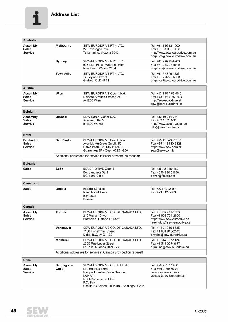
Australia
AssemblySalesService
Melbourne SEW-EURODRIVE PTY. LTD.27 Beverage DriveTullamarine, Victoria 3043
Tel. +61 3 9933-1000Fax +61 3 9933-1003http://[email protected]
Sydney SEW-EURODRIVE PTY. LTD.9, Sleigh Place, Wetherill Park New South Wales, 2164
Tel. +61 2 9725-9900Fax +61 2 [email protected]
Townsville SEW-EURODRIVE PTY. LTD.12 Leyland StreetGarbutt, QLD 4814
Tel. +61 7 4779 4333Fax +61 7 4779 [email protected]
Austria
AssemblySalesService
Wien SEW-EURODRIVE Ges.m.b.H. Richard-Strauss-Strasse 24A-1230 Wien
Tel. +43 1 617 55 00-0Fax +43 1 617 55 00-30http://[email protected]
Belgium
AssemblySalesService
Brüssel SEW Caron-Vector S.A.Avenue Eiffel 5B-1300 Wavre
Tel. +32 10 231-311Fax +32 10 231-336http://[email protected]
Brazil
ProductionSalesService
Sao Paulo SEW-EURODRIVE Brasil Ltda.Avenida Amâncio Gaiolli, 50Caixa Postal: 201-07111-970Guarulhos/SP - Cep.: 07251-250
Tel. +55 11 6489-9133Fax +55 11 6480-3328http://[email protected]
Additional addresses for service in Brazil provided on request!
Bulgaria
Sales Sofia BEVER-DRIVE GmbHBogdanovetz Str.1BG-1606 Sofia
Tel. +359 2 9151160Fax +359 2 [email protected]
Cameroon
Sales Douala Electro-ServicesRue Drouot AkwaB.P. 2024Douala
Tel. +237 4322-99Fax +237 4277-03
Canada
AssemblySalesService
Toronto SEW-EURODRIVE CO. OF CANADA LTD. 210 Walker Drive Bramalea, Ontario L6T3W1
Tel. +1 905 791-1553Fax +1 905 791-2999http://[email protected]
Vancouver SEW-EURODRIVE CO. OF CANADA LTD.7188 Honeyman Street Delta. B.C. V4G 1 E2
Tel. +1 604 946-5535Fax +1 604 [email protected]
Montreal SEW-EURODRIVE CO. OF CANADA LTD.2555 Rue Leger Street LaSalle, Quebec H8N 2V9
Tel. +1 514 367-1124Fax +1 514 [email protected]
Additional addresses for service in Canada provided on request!
Chile
AssemblySalesService
Santiago de Chile
SEW-EURODRIVE CHILE LTDA.Las Encinas 1295Parque Industrial Valle GrandeLAMPARCH-Santiago de ChileP.O. BoxCasilla 23 Correo Quilicura - Santiago - Chile
Tel. +56 2 75770-00Fax +56 2 [email protected]
11/2006
Address List
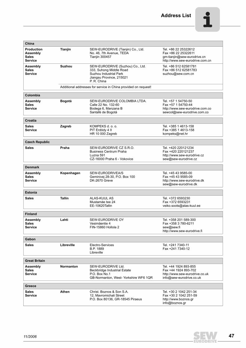
China
ProductionAssemblySalesService
Tianjin SEW-EURODRIVE (Tianjin) Co., Ltd.No. 46, 7th Avenue, TEDA Tianjin 300457
Tel. +86 22 25322612Fax +86 22 [email protected]://www.sew-eurodrive.com.cn
AssemblySalesService
Suzhou SEW-EURODRIVE (Suzhou) Co., Ltd.333, Suhong Middle RoadSuzhou Industrial ParkJiangsu Province, 215021P. R. China
Tel. +86 512 62581781Fax +86 512 [email protected]
Additional addresses for service in China provided on request!
Colombia
AssemblySalesService
Bogotá SEW-EURODRIVE COLOMBIA LTDA. Calle 22 No. 132-60Bodega 6, Manzana BSantafé de Bogotá
Tel. +57 1 54750-50Fax +57 1 54750-44http://[email protected]
Croatia
SalesService
Zagreb KOMPEKS d. o. o.PIT Erdödy 4 IIHR 10 000 Zagreb
Tel. +385 1 4613-158Fax +385 1 [email protected]
Czech Republic
Sales Praha SEW-EURODRIVE CZ S.R.O.Business Centrum Praha Luzna 591CZ-16000 Praha 6 - Vokovice
Tel. +420 220121234Fax +420 220121237http://[email protected]
Denmark
AssemblySalesService
Kopenhagen SEW-EURODRIVEA/SGeminivej 28-30, P.O. Box 100DK-2670 Greve
Tel. +45 43 9585-00Fax +45 43 9585-09http://[email protected]
Estonia
Sales Tallin ALAS-KUUL ASMustamäe tee 24EE-10620Tallin
Tel. +372 6593230Fax +372 [email protected]
Finland
AssemblySalesService
Lahti SEW-EURODRIVE OYVesimäentie 4FIN-15860 Hollola 2
Tel. +358 201 589-300Fax +358 3 [email protected]://www.sew-eurodrive.fi
Gabon
Sales Libreville Electro-ServicesB.P. 1889Libreville
Tel. +241 7340-11Fax +241 7340-12
Great Britain
AssemblySalesService
Normanton SEW-EURODRIVE Ltd.Beckbridge Industrial Estate P.O. Box No.1GB-Normanton, West- Yorkshire WF6 1QR
Tel. +44 1924 893-855Fax +44 1924 893-702http://[email protected]
Greece
SalesService
Athen Christ. Boznos & Son S.A.12, Mavromichali StreetP.O. Box 80136, GR-18545 Piraeus
Tel. +30 2 1042 251-34 Fax +30 2 1042 251-59http://[email protected]
11/2006 47
Address List
48
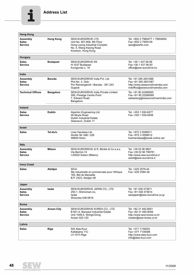
Hong Kong
AssemblySalesService
Hong Kong SEW-EURODRIVE LTD.Unit No. 801-806, 8th FloorHong Leong Industrial ComplexNo. 4, Wang Kwong Road Kowloon, Hong Kong
Tel. +852 2 7960477 + 79604654Fax +852 2 [email protected]
Hungary
SalesService
Budapest SEW-EURODRIVE Kft.H-1037 BudapestKunigunda u. 18
Tel. +36 1 437 06-58Fax +36 1 437 [email protected]
India
AssemblySalesService
Baroda SEW-EURODRIVE India Pvt. Ltd.Plot No. 4, GidcPor Ramangamdi • Baroda - 391 243Gujarat
Tel. +91 265 2831086Fax +91 265 2831087http://[email protected]
Technical Offices Bangalore SEW-EURODRIVE India Private Limited308, Prestige Centre Point7, Edward RoadBangalore
Tel. +91 80 22266565Fax +91 80 [email protected]
Ireland
SalesService
Dublin Alperton Engineering Ltd. 48 Moyle RoadDublin Industrial EstateGlasnevin, Dublin 11
Tel. +353 1 830-6277Fax +353 1 830-6458
Israel
Sales Tel-Aviv Liraz Handasa Ltd. Ahofer Str 34B / 22858858 Holon
Tel. +972 3 5599511Fax +972 3 [email protected]
Italy
AssemblySalesService
Milano SEW-EURODRIVE di R. Blickle & Co.s.a.s.Via Bernini,14 I-20020 Solaro (Milano)
Tel. +39 02 96 9801Fax +39 02 96 799781http://[email protected]
Ivory Coast
Sales Abidjan SICASte industrielle et commerciale pour l'Afrique165, Bld de MarseilleB.P. 2323, Abidjan 08
Tel. +225 2579-44Fax +225 2584-36
Japan
AssemblySalesService
Iwata SEW-EURODRIVE JAPAN CO., LTD 250-1, Shimoman-no,IwataShizuoka 438-0818
Tel. +81 538 373811Fax +81 538 [email protected]
Korea
AssemblySalesService
Ansan-City SEW-EURODRIVE KOREA CO., LTD. B 601-4, Banweol Industrial Estate Unit 1048-4, Shingil-DongAnsan 425-120
Tel. +82 31 492-8051Fax +82 31 492-8056http://[email protected]
Latvia
Sales Riga SIA Alas-KuulKatlakalna 11CLV-1073 Riga
Tel. +371 7139253Fax +371 7139386http://[email protected]
11/2006
Address List
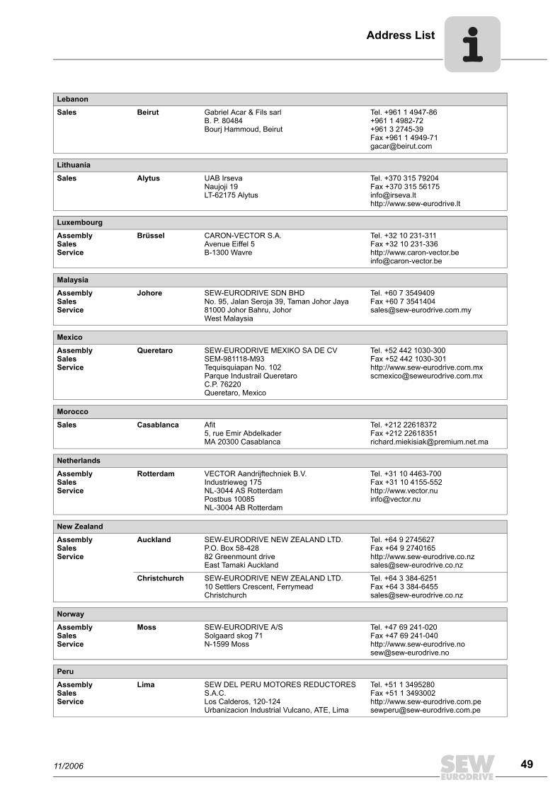
Lebanon
Sales Beirut Gabriel Acar & Fils sarlB. P. 80484Bourj Hammoud, Beirut
Tel. +961 1 4947-86 +961 1 4982-72+961 3 2745-39Fax +961 1 4949-71 [email protected]
Lithuania
Sales Alytus UAB IrsevaNaujoji 19LT-62175 Alytus
Tel. +370 315 79204Fax +370 315 [email protected]://www.sew-eurodrive.lt
Luxembourg
AssemblySalesService
Brüssel CARON-VECTOR S.A.Avenue Eiffel 5B-1300 Wavre
Tel. +32 10 231-311Fax +32 10 231-336http://[email protected]
Malaysia
AssemblySalesService
Johore SEW-EURODRIVE SDN BHD No. 95, Jalan Seroja 39, Taman Johor Jaya81000 Johor Bahru, JohorWest Malaysia
Tel. +60 7 3549409Fax +60 7 [email protected]
Mexico
AssemblySalesService
Queretaro SEW-EURODRIVE MEXIKO SA DE CVSEM-981118-M93Tequisquiapan No. 102Parque Industrail QueretaroC.P. 76220Queretaro, Mexico
Tel. +52 442 1030-300Fax +52 442 1030-301http://[email protected]
Morocco
Sales Casablanca Afit5, rue Emir AbdelkaderMA 20300 Casablanca
Tel. +212 22618372Fax +212 [email protected]
Netherlands
AssemblySalesService
Rotterdam VECTOR Aandrijftechniek B.V. Industrieweg 175 NL-3044 AS RotterdamPostbus 10085NL-3004 AB Rotterdam
Tel. +31 10 4463-700Fax +31 10 4155-552http://[email protected]
New Zealand
AssemblySalesService
Auckland SEW-EURODRIVE NEW ZEALAND LTD. P.O. Box 58-428 82 Greenmount driveEast Tamaki Auckland
Tel. +64 9 2745627Fax +64 9 2740165http://[email protected]
Christchurch SEW-EURODRIVE NEW ZEALAND LTD. 10 Settlers Crescent, FerrymeadChristchurch
Tel. +64 3 384-6251Fax +64 3 [email protected]
Norway
AssemblySalesService
Moss SEW-EURODRIVE A/SSolgaard skog 71N-1599 Moss
Tel. +47 69 241-020Fax +47 69 241-040http://[email protected]
Peru
AssemblySalesService
Lima SEW DEL PERU MOTORES REDUCTORES S.A.C.Los Calderos, 120-124Urbanizacion Industrial Vulcano, ATE, Lima
Tel. +51 1 3495280Fax +51 1 3493002http://[email protected]
11/2006
49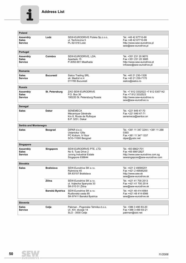
ddress List
50
Poland
AssemblySalesService
Lodz SEW-EURODRIVE Polska Sp.z.o.o.ul. Techniczna 5 PL-92-518 Lodz
Tel. +48 42 67710-90Fax +48 42 67710-99http://[email protected]
Portugal
AssemblySalesService
Coimbra SEW-EURODRIVE, LDA. Apartado 15 P-3050-901 Mealhada
Tel. +351 231 20 9670Fax +351 231 20 3685http://[email protected]
Romania
SalesService
Bucuresti Sialco Trading SRL str. Madrid nr.4 011785 Bucuresti
Tel. +40 21 230-1328Fax +40 21 230-7170 [email protected]
Russia
AssemblySalesService
St. Petersburg ZAO SEW-EURODRIVE P.O. Box 36 195220 St. Petersburg Russia
Tel. +7 812 3332522 +7 812 5357142Fax +7 812 3332523http://[email protected]
Senegal
Sales Dakar SENEMECA Mécanique GénéraleKm 8, Route de Rufisque B.P. 3251, Dakar
Tel. +221 849 47-70Fax +221 849 [email protected]
Serbia and Montenegro
Sales Beograd DIPAR d.o.o.Ustanicka 128aPC Košum, IV floorSCG-11000 Beograd
Tel. +381 11 347 3244 / +381 11 288 0393Fax +381 11 347 [email protected]
Singapore
AssemblySalesService
Singapore SEW-EURODRIVE PTE. LTD. No 9, Tuas Drive 2 Jurong Industrial Estate Singapore 638644
Tel. +65 68621701Fax +65 68612827http://[email protected]
Slovakia
Sales Bratislava SEW-Eurodrive SK s.r.o.Rybnicna 40SK-83107 Bratislava
Tel. +421 2 49595201Fax +421 2 49595200http://[email protected]
Zilina SEW-Eurodrive SK s.r.o.ul. Vojtecha Spanyola 33SK-010 01 Zilina
Tel. +421 41 700 2513Fax +421 41 700 [email protected]
Banská Bystrica SEW-Eurodrive SK s.r.o.Rudlovská cesta 85SK-97411 Banská Bystrica
Tel. +421 48 414 6564Fax +421 48 414 [email protected]
Slovenia
SalesService
Celje Pakman - Pogonska Tehnika d.o.o.UI. XIV. divizije 14SLO - 3000 Celje
Tel. +386 3 490 83-20Fax +386 3 490 [email protected]
A
11/2006
Address List
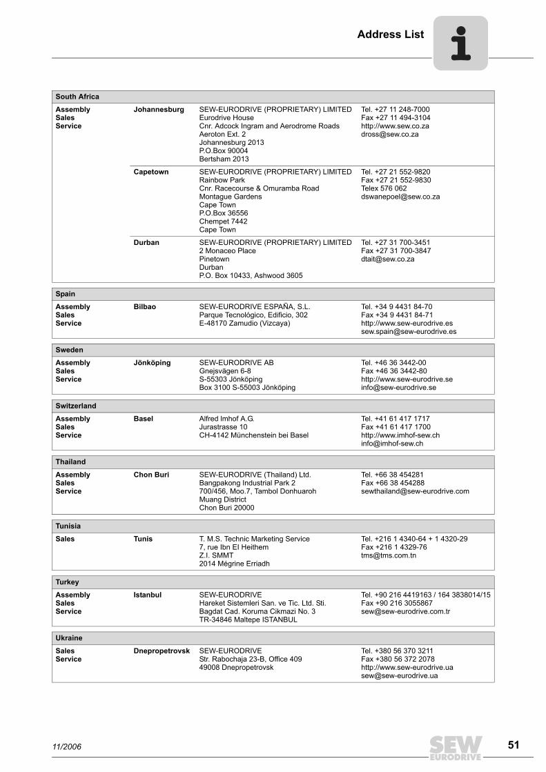
South Africa
AssemblySalesService
Johannesburg SEW-EURODRIVE (PROPRIETARY) LIMITEDEurodrive House Cnr. Adcock Ingram and Aerodrome RoadsAeroton Ext. 2Johannesburg 2013P.O.Box 90004Bertsham 2013
Tel. +27 11 248-7000Fax +27 11 494-3104http://[email protected]
Capetown SEW-EURODRIVE (PROPRIETARY) LIMITED Rainbow ParkCnr. Racecourse & Omuramba RoadMontague GardensCape TownP.O.Box 36556Chempet 7442 Cape Town
Tel. +27 21 552-9820Fax +27 21 552-9830Telex 576 [email protected]
Durban SEW-EURODRIVE (PROPRIETARY) LIMITED2 Monaceo PlacePinetownDurbanP.O. Box 10433, Ashwood 3605
Tel. +27 31 700-3451Fax +27 31 [email protected]
Spain
AssemblySalesService
Bilbao SEW-EURODRIVE ESPAÑA, S.L. Parque Tecnológico, Edificio, 302E-48170 Zamudio (Vizcaya)
Tel. +34 9 4431 84-70Fax +34 9 4431 84-71http://[email protected]
Sweden
AssemblySalesService
Jönköping SEW-EURODRIVE ABGnejsvägen 6-8S-55303 JönköpingBox 3100 S-55003 Jönköping
Tel. +46 36 3442-00Fax +46 36 3442-80http://[email protected]
Switzerland
AssemblySalesService
Basel Alfred lmhof A.G.Jurastrasse 10 CH-4142 Münchenstein bei Basel
Tel. +41 61 417 1717Fax +41 61 417 1700http://[email protected]
Thailand
AssemblySalesService
Chon Buri SEW-EURODRIVE (Thailand) Ltd.Bangpakong Industrial Park 2700/456, Moo.7, Tambol DonhuarohMuang DistrictChon Buri 20000
Tel. +66 38 454281Fax +66 38 [email protected]
Tunisia
Sales Tunis T. M.S. Technic Marketing Service7, rue Ibn EI Heithem Z.I. SMMT2014 Mégrine Erriadh
Tel. +216 1 4340-64 + 1 4320-29Fax +216 1 [email protected]
Turkey
AssemblySalesService
Istanbul SEW-EURODRIVE Hareket Sistemleri San. ve Tic. Ltd. Sti. Bagdat Cad. Koruma Cikmazi No. 3 TR-34846 Maltepe ISTANBUL
Tel. +90 216 4419163 / 164 3838014/15Fax +90 216 [email protected]
Ukraine
SalesService
Dnepropetrovsk SEW-EURODRIVEStr. Rabochaja 23-B, Office 40949008 Dnepropetrovsk
Tel. +380 56 370 3211Fax +380 56 372 2078http://[email protected]
11/2006
51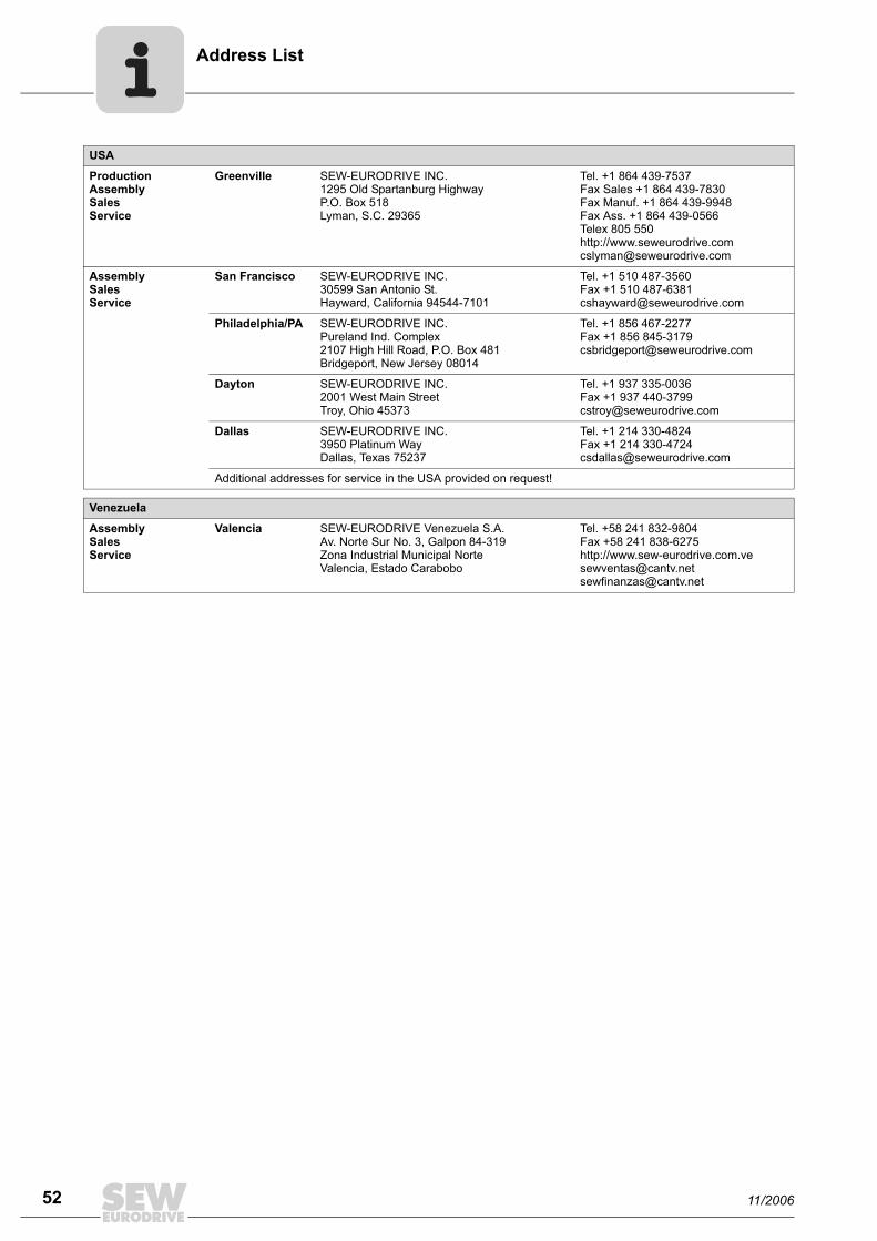
ddress List
52
USA
ProductionAssemblySalesService
Greenville SEW-EURODRIVE INC. 1295 Old Spartanburg Highway P.O. Box 518Lyman, S.C. 29365
Tel. +1 864 439-7537Fax Sales +1 864 439-7830Fax Manuf. +1 864 439-9948Fax Ass. +1 864 439-0566Telex 805 550 http://[email protected]
AssemblySalesService
San Francisco SEW-EURODRIVE INC. 30599 San Antonio St.Hayward, California 94544-7101
Tel. +1 510 487-3560Fax +1 510 [email protected]
Philadelphia/PA SEW-EURODRIVE INC. Pureland Ind. Complex 2107 High Hill Road, P.O. Box 481Bridgeport, New Jersey 08014
Tel. +1 856 467-2277Fax +1 856 [email protected]
Dayton SEW-EURODRIVE INC.2001 West Main Street Troy, Ohio 45373
Tel. +1 937 335-0036Fax +1 937 [email protected]
Dallas SEW-EURODRIVE INC.3950 Platinum Way Dallas, Texas 75237
Tel. +1 214 330-4824Fax +1 214 [email protected]
Additional addresses for service in the USA provided on request!
Venezuela
AssemblySalesService
Valencia SEW-EURODRIVE Venezuela S.A.Av. Norte Sur No. 3, Galpon 84-319Zona Industrial Municipal NorteValencia, Estado Carabobo
Tel. +58 241 832-9804Fax +58 241 838-6275http://[email protected]@cantv.net
A
11/2006


SEW-EURODRIVE – Driving the world

How we’re driving the world
With people whothink fast anddevelop thefuture with you.
With a worldwide service network that isalways close at hand.
With drives and controlsthat automaticallyimprove your productivity.
With comprehensiveknowledge in virtuallyevery branch ofindustry today.
With uncompromisingquality that reduces thecost and complexity ofdaily operations.
With a global presencethat offers responsive and reliable solutions. Anywhere.
With innovativetechnology that solvestomorrow’s problemstoday.
With online informationand software updates,via the Internet, availablearound the clock.
Gearmotors \ Industrial Gear Units \ Drive Electronics \ Drive Automation \ Services
SEW-EURODRIVEDriving the world
SEW-EURODRIVE GmbH & Co KGP.O. Box 3023 · D-76642 Bruchsal / GermanyPhone +49 7251 75-0 · Fax +49 7251 [email protected]
→ www.sew-eurodrive.com