Embed Size (px)
Citation preview

Gearmotors \ Industrial Gear Units \ Drive Electronics \ Drive Automation \ Services
Industrial Gear Units of theMC.. Series
Operating Instructions
GD110000
Edition 11/200511357614 / EN

SEW-EURODRIVE – Driving the world
Contents
1 Important Information about the Operating Instructions .............................. 51.1 Important information and designated use................................................ 51.2 Explanation of symbols ............................................................................. 61.3 Operating notes ........................................................................................ 6
2 Safety Notes ...................................................................................................... 72.1 Preface...................................................................................................... 72.2 General information .................................................................................. 72.3 Personal protective equipment ................................................................. 82.4 Transport of industrial gear units .............................................................. 92.5 Corrosion and surface protection ........................................................... 13
3 Gear Unit Design ............................................................................................. 173.1 Basic design of industrial gear units of the MC..P.. series...................... 173.2 Basic design of industrial gear units of the MC..R.. series...................... 183.3 Unit designation / nameplates................................................................. 193.4 Mounting positions .................................................................................. 263.5 Mounting surface .................................................................................... 263.6 Housing orientation M1...M6 ................................................................... 273.7 Shaft positions ....................................................................................... 293.8 Direction of rotation................................................................................. 313.9 Lubrication of industrial gear units .......................................................... 35
4 Mechanical Installation................................................................................... 394.1 Required tools / resources ...................................................................... 394.2 Before you begin..................................................................................... 394.3 Preliminary work ..................................................................................... 394.4 Gear unit foundation ............................................................................... 404.5 Mounting of solid shaft gear units ........................................................... 474.6 Mounting / removing hollow shaft gear units with keyed connection ...... 494.7 Mounting / removing hollow shaft gear units with shrink disc ................. 514.8 Mounting a motor with motor adapter ..................................................... 57
5 Mechanical Installation Options .................................................................... 605.1 Important installation instructions............................................................ 605.2 Mounting of couplings ............................................................................. 635.3 Backstop FXM......................................................................................... 785.4 Shaft end pump SHP .............................................................................. 815.5 Installation with steel frame..................................................................... 845.6 Torque arm ............................................................................................. 855.7 Mounting of V-belt drive .......................................................................... 885.8 Oil heater ................................................................................................ 915.9 Temperature sensor PT100 .................................................................... 975.10 SPM adapter ........................................................................................... 985.11 Fan.......................................................................................................... 995.12 Flow switch ........................................................................................... 1005.13 Visual flow indicator .............................................................................. 1035.14 Connecting the oil/water cooling system............................................... 1045.15 Connecting the oil/air cooling system ................................................... 1045.16 Connecting the motor pump.................................................................. 104
6 Startup............................................................................................................ 1056.1 Startup of MC gear units ....................................................................... 1056.2 Startup of MC gear units with backstop ................................................ 1066.3 Startup of MC gear units with steel oil expansion tank ......................... 1066.4 Taking MC gear units out of operation.................................................. 109
7 Inspection and Maintenance ........................................................................ 1107.1 Inspection and maintenance intervals................................................... 1107.2 Lubricant change intervals .................................................................... 1117.3 Inspection and maintenance of the gear unit ........................................ 112
8 Malfunctions .................................................................................................. 1188.1 Gear unit malfunctions .......................................................................... 118
Operating Instructions – Gear Units of the MC.. Series 3
Contents
4
9 Mounting Positions...................................................................................... 1199.1 Symbols used ....................................................................................... 1199.2 Mounting positions of MC.P.. gear units ............................................... 1209.3 Mounting positions of MC.R.. gear units ............................................... 121
10 Design and Operating Notes........................................................................ 12210.1 Guideline for oil selection...................................................................... 12210.2 Lubricants for MC.. industrial gear units ............................................... 12610.3 Grease .................................................................................................. 12810.4 Lubricant fill quantities .......................................................................... 129
11 Change Index................................................................................................. 13011.1 Changes to the previous edition ........................................................... 130
12 Index............................................................................................................... 132
Operating Instructions – Industrial Gear Units of the MC.. Series
1Important information and designated useImportant Information about the Operating Instructions
1 Important Information about the Operating Instructions1.1 Important information and designated use
Integral part of the productThe operating instructions are part of the MC.. industrial gear units and containimportant information for operation and service. The operating instructions are writtenfor assembly, installation, startup and service employees who are involved in theinstallation and maintenance of MC.. industrial gear units.
Designated useThe designated use refers to the procedure specified in the operating instructions.
The MC.. industrial gear units are units run by motors for industrial and commercialsystems. Gear unit utilizations other than those specified and areas of application otherthan industrial and commercial systems can only be used after consultation with SEW-EURODRIVE.
In compliance with the EG Machinery Directive 2006/42/EC, the MC.. industrial gear unitsare components for installation in machinery and systems. In the scope of the EGdirective, you must not take the machinery into operation in the designated fashion untilyou have established that the end product complies with the Machinery Directive2006/42/EC.
Qualified personnelMC.. industrial gear units may represent a potential hazard for persons and material.Consequently, assembly, installation, startup and service work may only be performedby trained personnel who are aware of the potential hazards.
The personnel must be appropriately qualified for the task in hand and must be familiarwith the assembly, installation, startup and operation of the product. The personnel mustread the operating instructions, in particular the safety notes section, carefully andensure that they understand and comply with them.
Liability for defectsIncorrect handling or any action performed that is not specified in these operatinginstructions could impair the properties of the product. In this case, you lose any right toclaim under limited warranty against SEW-EURODRIVE GmbH & Co KG.
Product names and trademarksThe brands and product names contained within these operating instructions aretrademarks or registered trademarks of the titleholders.
Waste disposal (Please follow the latest instructions):
• Housing parts, gears, shafts and roller bearings of the gear units must be disposedof as steel scrap. This also applies to gray-cast iron parts if there is no specialcollection.
• Collect waste oil and dispose of it according to the regulations in force.
Operating Instructions – Industrial Gear Units of the MC.. Series
5
6
1 xplanation of symbolsmportant Information about the Operating Instructions
1.2 Explanation of symbols
1.3 Operating notes
Hazard
Indicates an imminently hazardous situation which, if not avoided, WILL result in deathor serious injury.
Warning
Indicates an imminently hazardous situation caused by the product which, if notavoided, WILL result in death or serious injury. You will also find this signal to indicatethe potential for damage to property.
Caution
Indicates a potentially hazardous situation which, if not avoided, MAY result in minorinjury or damage to products.
Note
Indicates a reference to useful information, e.g. on startup.
Documentation reference
Indicates a reference to a document, such as operating instructions, catalog, data sheet.
• It is essential to contact SEW-EURODRIVE regarding a subsequent change ofmounting position!
• The industrial gear units of the MC.. series are delivered without oil fill. Referto the information on the nameplate!
• Refer to the instructions in the sections "Mechanical Installation" and"Startup"!
EI
Operating Instructions – Industrial Gear Units of the MC.. Series

2PrefaceSafety Notes
2 Safety Notes2.1 Preface
2.2 General information
During or after operation, industrial gear units and motors have:
• Live parts
• Moving parts
• Hot surfaces (may be the case)
Only qualified personnel may carry out the following work:
• Installation / assembly
• Connection
• Startup
• Maintenance
• Servicing
The following information and documents must be observed during these processes:
• Relevant operating instructions and wiring diagrams
• Warning and safety signs on the gear unit
• System-specific regulations and requirements
• National / regional regulations governing safety and the prevention of accidents
The following safety notes are concerned with the use of MC.. industrial gear units.
If using gearmotors, please also refer to the safety notes for motors in the correspondingoperating instructions.
Please also consider the supplementary safety notes in the individual sections ofthese operating instructions.
Never install damaged products or take them into operation.
Submit a complaint to the shipping company immediately in the event of damage.
Serious injuries and property damage may result from:
• Improper use
• Incorrect installation or operation
• Unauthorized removal of necessary protection covers or the housing
Operating Instructions – Industrial Gear Units of the MC.. Series
7
8
2 ersonal protective equipmentafety Notes
Transportation Inspect the shipment for any damage in transit as soon as you receive thedelivery. Inform the shipping company immediately. It may be necessary topreclude startup.
Startup / operation
Secure the key for test mode without output elements. Do not deactivate monitoring andprotection equipment even for testing.
Switch off the main motor if in doubt whenever changes occur in relation to normaloperation (e.g. increased temperature, noise, vibration). Determine the cause andcontact SEW-EURODRIVE, if required.
Inspection / maintenance
Refer to the instructions in Sec. "Inspection and Maintenance."
2.3 Personal protective equipment
Always wear the following when carrying out work on the gear unit:
• Tight-fitting clothing (not prone to tear, no loose sleeves, no rings, etc.).
• Safety glasses for protecting the eyes from falling objects and liquids.
• Safety shoes for protection against heavy falling objects and slipping on a slipperyfloor.
• Hearing protection for protection against hearing damage for sound pressure levelsexceeding 80 dB (A).
Check that the direction of rotation is correct in decoupled status. Listen out forunusual grinding noises as the shaft rotates
PS
Operating Instructions – Industrial Gear Units of the MC.. Series

2Transport of industrial gear unitsSafety Notes
2.4 Transport of industrial gear units
Transport eyebolts
Tighten screwed in transport eyebolts [1] firmly. They are only designed for the weightof the industrial gear unit including the motor connected via motor adapter; do not attachany additional loads.
• The main gear unit must only be lifted using lifting ropes or chains on the twoscrewed in transport eyebolts on the main gear unit. The weight of the gear unitis indicated on the nameplate or the dimension sheet. The loads and regula-tions specified on the nameplate must always be observed.
• The length of the lifting chains or ropes must be dimensioned in such a waythat the angle between the chains or ropes does not exceed 45°.
• Eyebolts on the motor, auxiliary gear unit or primary gear unit must not beused for transport (→ following figures)!
Vertical mounting position (V)
Upright mounting position (E)
Horizontal mounting position (L)
51375AXXFigure 1: Positions of transport eyebolts
52086AXXFigure 2: Do not use eyebolts on the motor for transport
[1]
[1][1]
[1]
Operating Instructions – Industrial Gear Units of the MC.. Series
9
10
2 ransport of industrial gear unitsafety Notes
• Use suitable, sufficiently rated handling equipment if necessary. Beforestartup, remove securing devices used for transport.
Transport of MC.. industrial gear units with motor adapter
Industrial gear units of the MC.P.. / MC.R.. series with motor adapter (→ followingfigure) must only be transported using lifting ropes/chains [2] or lifting belts [1] atan angle of 90° (vertically) to 70°.
52112AXXFigure 3: Do not use eyebolts on the motor for transport
52110AXXFigure 4: Transport of industrial gear unit with motor adapter – Do not use eyebolts on the motor for transport
90°-70°[1] [2]
<70°[1][2]
TS
Operating Instructions – Industrial Gear Units of the MC.. Series
2Transport of industrial gear unitsSafety Notes
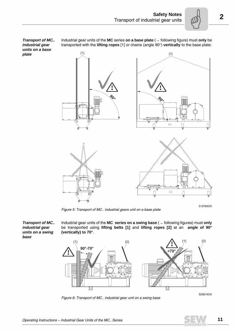
Transport of MC.. industrial gear units on a base plate
Industrial gear units of the MC series on a base plate (→ following figure) must only betransported with the lifting ropes [1] or chains (angle 90°) vertically to the base plate:
Transport of MC.. industrial gear units on a swing base
Industrial gear units of the MC series on a swing base (→ following figures) must onlybe transported using lifting belts [1] and lifting ropes [2] at an angle of 90°(vertically) to 70°.
51376AXXFigure 5: Transport of MC.. industrial gears unit on a base plate
90° 90°
[1] [1]
52081AXXFigure 6: Transport of MC.. industrial gear unit on a swing base
90°-70°<70°
[1] [2] [1] [2]
Operating Instructions – Industrial Gear Units of the MC.. Series
11
12
2 ransport of industrial gear unitsafety Notes
Transport of MC.. industrial gear units with V-belt drive
Industrial gear units of the MC series with V-belt drive must only be transported usinglifting belts [1] and lifting ropes [2] at an angle of 90° (vertically). The eyebolts onthe motor must not be used for transport.
52111AXXFigure 7: Transport of MC.. with V-belt drive
[1] [1]
[2]
90°
90°
[1][1]
[2]
TS
Operating Instructions – Industrial Gear Units of the MC.. Series

2Corrosion and surface protectionSafety Notes
2.5 Corrosion and surface protection
Introduction The corrosion and surface protection of gear units comprises the following three basicfeatures:
1. Painting system
• Standard painting system K7 E160/2• High-resistant painting system K7 E260/3 as option
2. Gear unit corrosion protection with
• interior protection and• exterior protection
3. Gear unit packing
• Standard packing (palette)• Wooden box• Seaworthy packing
Standard painting system K7 E 160/2
Painting is performed according to TEKNOS EPOXY SYSTEM K7, which is based onthe high-solid epoxy paint TEKNOPLAST HS 150.
Color shade: RAL 7031, blue gray
Guards and shields
Powder coating, epoxy-based coat paint (EP) is used for guards and shields.
Layer thickness 65 µm
Color shade: TM 1310 PK, warning in yellow color
High-resistant painting system K7 E 260/3
Painting is performed according to TEKNOS EPOXY SYSTEM K7, which is based onthe high-solid epoxy paint TEKNOPLAST HS 150.
Optional color shade
Other color shades are possible on request.
The information in this chapter is valid for MC units assembled in Europe. For other re-gions, other painting systems might be applied. Please contact your local SEW-EURO-DRIVE assembly center for MC.. units.
Two layer system K7 E 160/2 Thickness
• Epoxy primer 60 µm
• Teknoplast HS 150 100 µm
TOTAL 160 µm
Three-layer system, E 260/3 thickness
• Epoxy primer 60 µm
• Teknoplast HS 150 2x100 µm
TOTAL 260 µm
Operating Instructions – Industrial Gear Units of the MC.. Series
13
14
2 orrosion and surface protectionafety Notes
Usage of painting system
Storage and transport conditions
Industrial gear units of the MC.. series are delivered without oil fill. Different protectionsystems are required depending on storage period and ambient conditions:
Standard protection / interior
• Gear units undergo a test run with oil. The oil is drained by SEW-EURODRIVE beforedispatch. The remaining layer of oil on the inner parts serves as basic protection.
Standard protec-tion / exterior
• Oil seals and seal surfaces are protected by suitable grease.
• Unpainted surfaces (including spare parts) are covered with a protective coating.Before other equipment is mounted to such surfaces, the protective coating must beremoved using a solvent.
• Small spare parts and loose pieces, such as screws, nuts, etc., are supplied incorrosion protected plastic bags (VCI corrosion protection bag).
• Threaded holes and blind holes are covered by plastic plugs.
• The breather plug (position → chapter "Mounting Positions") is already installed.
Environmental pollution
None Low Medium High Very high
Typical environ-mental conditions
Unheated build-ings where con-densation might
occur
Atmospheres with low pollution,
mostly rural areas
Production rooms with high level of moistureand low
air pollution
City and industrial atmospheres,
moderate pollution with sulphur diox-
ide,coastal areas with
low salt load
Industrial areas and costal areas
with moderate salt load
Chemical plants
Buildings or areas with almost per-
manent condensa-tion and high
pollution
Industrial areas with very high lev-
els of moisture and aggressive atmospheres
Mounting Indoors IndoorsIndoors or outdoors
Indoors or outdoors
Indoors or outdoors
Relative humidity < 90 % up to 95 % up to 100 % up to 100 % up to 100 %
Recommended painting system
Standard painting system
K7 E160/2
Standard painting system
K7 E160/2
Standard painting system
K7 E160/2
High resistant paint-ing system K7 E260/3
Contact SEW-EURODRIVE
Storage period: up to
… months
Storage conditionsGear unit corrosion protection
Transport conditionsGear unit packing
OUTDOORS, roofedINDOORS, heated
(0…+20°C)
Storage area close to sea OUT-DOORS, roofed
Storage area close to sea INDOORS
Land transport
Seatransport
6 Standard protection
Standard protection
Contact SEW-EURODRIVE
Long-term protection
Standard packing
Seaworthy packing
12 ContactSEW-EURODRIVE
Standardprotection
Contact SEW-EURODRIVE
Long-term protection
Standard packing
Seaworthy packing
24 Long-term protection
Contact SEW-EURODRIVE
ContactSEW-EURODRIVE
Long-termprotection
Standardpacking
Seaworthy packing
36 Contact SEW-EURODRIVE
Long-termprotection
ContactSEW-EURODRIVE
Long-termprotection
Standard packing
Seaworthy packing
CS
Operating Instructions – Industrial Gear Units of the MC.. Series

2Corrosion and surface protectionSafety Notes
Standard protec-tion / packing
Standard packing is used: The gear unit is delivered on a palette without cover
Long-term protection / interior
The following procedure is applied in addition to the "standard protection":
• A VPI solvent is sprayed through the oil filling hole
• The breather plug is replaced with a screw plug (before startup, the screw plug mustbe replaced again by the breather plug, which is attached to the gear unit separately)
55871AXXFigure 8: Standard protection / packing
• If the gear unit is stored longer than 6 months, it is recommended to regularlycheck the protective coating of unpainted areas as well as the paint coat. Areaswith removed protection coating or paint have to be repainted, if necessary.
• The LSS must be rotated at least one turn in such a way that the position of theroller elements in the bearings of LSS and HSS changes. This procedure hasto be repeated every 6 months until startup.
• Never open the gear unit near open flames, sparks and hot objects becausesolvent vapors might be ignited.
• Take preventive measures to protect people from solvent vapors. It is abso-lutely crucial that open flames are avoided when the solvent is applied andwhen the solvent evaporates.
Operating Instructions – Industrial Gear Units of the MC.. Series
15
16
2 orrosion and surface protectionafety Notes
Long-term protection / exterior
• Oil seals and seal surfaces are protected through suitable grease
• Unpainted surfaces (including spare parts) are covered with a protective coating.Before other equipment is mounted to such surfaces, the protective coating must beremoved using a solvent.
• Small spare parts and loose pieces, such as screws, nuts, etc., are supplied incorrosion protected plastic bags (VCI corrosion protection bag).
• Threaded holes and blind holes are covered by plastic plugs
• The breather plug (Position → chapter "Mounting Positions") is already installed.
Long-term pro-tection / packing
• Seaworthy packing is used: The gear unit is packed in a seaworthy plywood box witha wooden frame
Alternative packing
Optionally, the gear unit can be supplied in a wooden box with standard gear unitprotection.
57585AXXFigure 9: Long-term protection / packing
• If the gear unit is stored for longer than 6 months, it is recommended toregularly check the protective coating of unpainted areas as well as the paintcoat. Areas with removed protection coating or paint have to be repainted, ifnecessary.
• The LSS must be rotated at least one turn in such a way that the position of theroller elements in the bearings of LSS and HSS changes. This procedure mustbe repeated every 6 months until startup.
• The interior long-term protection with the VPI solvent has to be repeated every24 / 36 months (according to the table "Storage and transport conditions") untilstartup.
CS
Operating Instructions – Industrial Gear Units of the MC.. Series

3Basic design of industrial gear units of the MC..P.. seriesGear Unit Design
3 Gear Unit Design
3.1 Basic design of industrial gear units of the MC..P.. series
The following illustrations serve to explain the general design. Their only purpose is tofacilitate the assignment of components to the spare parts lists. Discrepancies arepossible depending on gear unit size and version!
51718AXXFigure 10: Basic design of industrial gear units of the MC..P.. series
[001] Gear unit housing [131] Key [299] Gear wheel [410] Bearing
[010] Bearing cover [180] Oil seal [301] Pinion shaft [411] Bearing
[015] Bearing cover [195] Shim [310] Bearing [430] Key
[025] Bearing cover [199] Output gear wheel [331] Key [434] Cover
[040] Bearing cover [201] Pinion shaft [340] Distance bushing [438] Bushing
[070] Housing cover [210] Bearing [342] Distance bushing [443] Distance bushing
[075] Assembly cover [231] Key [395] Shim [480] Oil seal
[100] Output shaft [242] Distance piece [399] Gear wheel [495] Shim
[110] Bearing [243] Distance piece [401] Input shaft [725] Lifting eyebolt
[130] Key [295] Shim
[015][195]
[110]
[131]
[130]
[100]
[040]
[231]
[201][210]
[295][242]
[342]
[434][395]
[310]
[340]
[438][480]
[495][411]
[401][430]
[070]
[199]
[725]
[299]
[110]
[180]
[195]
[010]
[295]
[210]
[243][025]
[342]
[395]
[310]
[331]
[301]
[399] [443]
[410][495 ]
[001]
[725]
MC2P..
[075]
Operating Instructions – Industrial Gear Units of the MC.. Series
17
18
3 asic design of industrial gear units of the MC..R.. seriesear Unit Design
3.2 Basic design of industrial gear units of the MC..R.. series
51399AXXFigure 11: Basic design of industrial gear units of the MC..R.. series
[001] Gear unit housing [131] Key [299] Gear wheel [410] Bearing
[010] Bearing cover [180] Oil seal [301] Pinion [411] Bearing
[015] Bearing cover [195] Shim [310] Bearing [422] Bearing bushing
[025] Bearing cover [199] Output gear wheel [331] Key [423] Bearing bushing
[040] Cover [201] Pinion shaft [340] Distance bushing [430] Key
[070] Housing cover [210] Bearing [341] Distance bushing [436] Sleeve
[080] Bearing cover [231] Key [342] Distance bushing [470] Tightening nut
[100] Output shaft [242 ]Distance bushing [395] Shim [480] Oil seal
[110] Bearing [243] Distance bushing [399] Bevel gear [495] Shim
[130] Key [295] Shim [401] Bevel pinion shaft [725] Lifting eyebolt
[015][195]
[110]
[070]
[199]
[725]
[299]
[110]
[180]
[195]
[010]
[725]
[231]
[201][210]
[295][242]
[342]
[395][310]
[025]
[342] [25]
[395]
[310]
[295]
[210]
[243]
[331]
[301]
[340]
[341][399]
[040]
[480]
[423]
[080]
[436]
[470]
[411]
[495]
[410]
[401][001]
[422]
[430]
[131][100]
BG
Operating Instructions – Industrial Gear Units of the MC.. Series

3Unit designation / nameplatesGear Unit Design
3.3 Unit designation / nameplates
Sample unit designation
MC 2 R L S F 05
Size: 02 ... 09
Gear unit mounting:F = Foot mountingT = Torque arm
Low speed shaft type (LSS):S = Solid shaftH = Hollow shaft (key or shrink disc connection)
Gear unit design:L = HorizontalV = VerticalE = Upright
Gear unit type:R = Bevel-helical gear unitP = Helical gear unit
Number of gear stages:2 = Two stages3 = Three stages
Industrial gear unit series
Operating Instructions – Industrial Gear Units of the MC.. Series
19
20
3 nit designation / nameplatesear Unit Design
Example: Nameplate of the MC.. series industrial gear unit, SEW-EURODRIVE
57523AXX
SEW-EURODRIVESEW-EURODRIVE Bruchsal / Germany
Type
Nr. 1
PK1
norm. min. max.
MK2
n1
n2
Operation instructione have to be observed!
Made by
Nr. 2
i
FS
FR1
FR2
FA1
1 :
[kN]
[kN]
[kN]
[kN]FA2
[kg]
Year
Mass
[kW]
[kNm]
[1/min]
[1/min]
Lubricant
Qty of greasing points Fans
MC3RLSF02
16.5
2.04
1500
73.8
16.5
2.04
1500
73.8
16.5
2.04
1500
73.8
SEW -Finland
2
Mineral Oil ISO VG 460 EPPAO - 7 ltr. 2003
219
0
0
0
0
3.64
20.3123
K346303 30764647
0
Typ Unit designation
Nr. 1 Serial number 1: Eurodrive order number (e.g. SAP-order number)
Nr. 2 Serial Number 2: (factory / assembly center manufacturing number)
PK1
norm.
[kW]
Running power on gear unit input @ n1 norm.
min. Running power on gear unit output @ n1 min.
max Running power on gear unit output @ n1 max.
MK2
norm.
[kNm]
Running torque on gear unit output @ n1 norm.
min. Running torque on gear unit output @ n1 min.
max Running torque on gear unit output @ n1 max.
n1
norm.
[1/min]
Input speed (HSS)
min. Minimum existing input speed (HSS)
max Maximum existing input speed (HSS)
n2
norm.
[1/min]
Output speed (LSS)
min. Minimum existing output speed (LSS)
max Maximum existing output speed (LSS)
Made by Location of gear unit assembly / manufacturing
norm. normal operation point
min. minimum operation point
max. maximum operation point
i Exact gear unit reduction ratio
FS Service factor
FR1 [kN] Existing radial load on HSS
FR2 [kN] Existing radial load on LSS
FA1 [kN] Existing axial load on HSS
FA2 [kN] Existing axial load on LSS
Mass [kg] Gear unit weight
UG
Operating Instructions – Industrial Gear Units of the MC.. Series

3Unit designation / nameplatesGear Unit Design
Example: Nameplate of the MC.. series industrial gear unit, SEW-EURODRIVE
Qty of greasing points:Number of points that require regreasing (e.g. in case of regreasable labyrinthseals or drywell sealing system)
Fans Number of cooling fans mounted on gear unit
Lubricant Oil grade and viscosity class / oil volume
Year Year of assembly
IM Mounting Position: Housing orientation and mounting surface
TU Temperature permitted range of ambient
57524AXX
Typ Unit designation
Nr. 1 Serial number 1
Nr. 2 Serial number 2
Pe [kW] Absorbed power on the input shaft
FS Service factor
n [r/min] Input/output speed
kg Weight
i Exact gear unit reduction ratio
Lubricant Oil grade and viscosity class / oil volume
MN2 [kNm] Rated torque of the gear unit
Year Year of manufacture
Number of greasing points
Number of points that require regreasing
MC3RLHF07
01.3115835301.0001.02
55
1.6 780
61.883 : 1 2004
1480/23.9
CLP 220 Miner..Oil/ca. 33 liter4
Year
MN2 kNm
Nr. 2
Made by SEWNumber of greasing points:
Lubricant
kg
i 1:
n r/min
Fs
Pe kW
Nr. 1
Typ
Bruchsal/Germany
1332
359
8.10
35.6
T34567
4
Operating Instructions – Industrial Gear Units of the MC.. Series
21
22
3 nit designation / nameplatesear Unit Design
Example: Nameplate of the MC series industrial gear unit, SEW-EURODRIVE China
Example: Nameplate of the MC series industrial gear unit, SEW-EURODRIVE Singapore
51965AXX
-EURODRIVESEW-EURODRIVE SEW-EURODRIVE
Type MC3PLHF04S.O.
Pe1831208.1
0Ma Nm
na
kg
ne r / min r / min
i
KW
IM351012345 . 01 . 35001PK1 = 55 6 . 65 KNM
65150023 . 2042
ISO VG460
Refer to lubrication schedule
13
Type Unit designation
IM Shaft position
Pe [kW] Absorbed power on the intput shaft
Ma [Nm] Output torque on the output shaft
ne [r/min] Input speed
na [r/min] Output speed
i Exact gear unit reduction ratio
S.O. Order number
51351AXX
-EURODRIVESEW-EURODRIVE SEW-EURODRIVE
Type MC3PLHF04PTE LTD Singapore
S.O.
Pe
1831208.1
0
Ma Nm
na
kg
ne r / min r / min
i
KW
IM351012345 . 01 . 35001PK1 = 55 6 . 65 KNM
65150023 . 2042
ISO VG460
Refer to lubrication schedule Assembled in Singapore
13
Type Unit designation
IM Shaft position
Pe [kW] Absorbed power on the intput shaft
Ma [Nm] Output torque on the output shaft
ne [r/min] Input speed
na [r/min] Output speed
i Exact gear unit reduction ratio
S.O. Order number
UG
Operating Instructions – Industrial Gear Units of the MC.. Series

3Unit designation / nameplatesGear Unit Design
Example: Nameplate of the MC series industrial gear unit, SEW-EURODRIVE Brazil
51598AXX
-EURODRIVESEW DO BRASIL LTDA SEW DO BRASIL LTDA Typo
No
Pe
ne
MC3PLS07
7001.11383446/301.001
148
1780
25.2024
R o d . P r e s . D u t r a K m 2 0 8
CEP07210-000 GUARUHOS-SP
C.G.C. 46.648.061/0001-99
1831151.1
0Ma Nm
na
kg
rpm rpm
i
1.45
BR1Use Mobil
OLEO ISO VG 460 EP _ 45 LITROS
fs
KW
IM
19.100
70.6
Lubrificaçâo conforme Manual Industria Brasileira
13
Typo Unit designation
No Order number
Pe [kW] Absorbed power on the input shaft
Ma [Nm] Output torque on the output shaft
ne [rpm] Input speed
na [rpm] Output speed
i Exact gear unit reduction ratio
IM Shaft position
fS Service factor
Operating Instructions – Industrial Gear Units of the MC.. Series
23
24
3 nit designation / nameplatesear Unit Design
Example: Nameplate of the MC series industrial gear unit, SEW-EURODRIVE USA
51349AXX
SEW -EURODRIVESEW-EURODRIVE, INC. USASEW-EURODRIVE, INC. USA Compact Reducer
Type
S.O.
In rpm rpmOut
Torque
Min Amb °C °CMax Amb
ServiceFactor
Ib-inHP
Ratio
ShaftPosition
Lubrication
See Operating Instructions
MC3PESF03
1750 15 . 160 . 4421 . 50
15
24 0 40SYN. ISOV6460-7EP: 8 GALS
116 . 9634
870111234 . 02 . 02 . 001
MEMBER OF
Type Unit designation
In [rpm] Input speed
Out [rpm] Output speed
HP [HP] Absorbed power on the output shaft
Torque [lb-in] Output torque
Ratio Exact gear unit reduction ratio
Service Factor Service factor
Shaft Position Shaft position
Min Amb [°C] Minimum ambient temperature
Max Amb [°C] Maximum ambient temperature
Lubrication Oil grade and volume
S.O. Shop order number
UG
Operating Instructions – Industrial Gear Units of the MC.. Series

3Unit designation / nameplatesGear Unit Design
Example: Nameplate of the MC series industrial gear unit, SEW-EURODRIVE Chile
56624AXX
SEW EURODRIVESEW EURODRIVE
MobilMobil®
LAS ENCINAS 1295 LAMPASANTIAGO - CHILE
Lubricación según manual instrucciones. Fono : 7577000 Fax : 7577001
Lubricado con:
Tipo
N°
Pe KW Nm
IM
rpm
mm.
Kg.
Lts
ne
F.C.
Peso
Øa
na
Ma
Cant Lubr.
Tipo Lubr.
Identif. (Tag)
f.s.
i
MC3PLSF05
517
1 4
1 2 053 .81 990 0
2 4ISOVG2 2 0 MINERAL
GRASA EP 22 . 1 53 2 .52 8175055
56131918040156RCH0113
Tipo Unit designation
No Serial number 1
F.C. Shaft position
Pe [kW] Input power
ne Input speed
i Exact gear unit reduction ratio
f.s. Service factor
Identif. Grease type
Tipo Lubr. Oil grade and viscosity class
Cant Lubt. Oil quantity
Ma [Nm] Gear unit nominal torque
na [rpm] Output speed
∅ a [mm] LSS shaft diameter
Peso [Kg] Weight of gear unit
Operating Instructions – Industrial Gear Units of the MC.. Series
25
26
3 ounting positionsear Unit Design
3.4 Mounting positions
The following features clearly define the mounting position and corresponding design ofMC units:
• Mounting surface (F1...F6) → chapter 3.5
• Housing orientation (M1...M6) → chapter 3.6
In addition, the shaft positions (0...4) have to be defined → chapter 3.7
The gear designs "horizontal LSS (L)", "vertical LSS (V)", "upright mounting (E)" areassociated with the housing orientation
3.5 Mounting surface
Definition The mounting surface is defined as the surface(s) of the foot or flange mounted gear unitto which the customer’s machine is mounted.
Designations Six different mountings surfaces have been defined (designations "F1" to "F6"):
54498AXXFigure 12: Mounting surface
F1
F3
F4
F5
F6
F2
MG
Operating Instructions – Industrial Gear Units of the MC.. Series

3Housing orientation M1...M6Gear Unit Design
3.6 Housing orientation M1...M6
The housing orientation is defined as the position of the housing in space and is definedusing the designations M1....M6.
Each housing orientation corresponds to a certain
• gear unit design (L, V, E)
• standard mounting surface (F1...F6)
Standard correla-tion of gear unit design and hous-ing orientation
For gear units with mounting flange on the LSS, the standard position of the flangedepends on the shaft position of the LSS unless specified otherwise:
• Shaft position 3 → LSS mounting flange F3
• Shaft position 4 → LSS mounting flange F4
The housing orientation is defined separately for
• MC.P.. helical units
• MC.R.. bevel-helical units
Unless specified otherwise, the standard correlation of
• gear unit design and
• housing orientation and
• mounting surface
is as follows (foot mounted gear units):
MC..PL: M1, F1
MC..PV: M5, F3
MC..PE: M4, F6
MC..RL: M1, F1
MC..RV: M5, F3
MC..RE: M4, F6
Operating Instructions – Industrial Gear Units of the MC.. Series
27
28
3 ousing orientation M1...M6ear Unit Design
Housing orientation and standard mounting surface
• The units marked in gray are standard design.
• Other mounting surfaces are possible in conjunction with a certain housing orienta-tion. Please refer to order-specific dimension drawing.
It is not allowed to change the housing orientation and/or mounting surface devi-ating from the order.
F6MC..PEM2
MC..PLM1
MC..PLM1
F1
1
1
32
2
43
4
MC..PEM4
1
3
3
2
2
4
F6
F6
F6
MC..RV
M2
F3
M5
M6
MC..RL
F1
M1
MC..RLM3
F1
F3
3
3
3
33
0
0
0
0
0
0
4
4
4
44
4
M4
MC..RE
MC..RV
MC..RE
MC..RVF3
F3
M6
MC..RLM1
MC..REM2
MC..RVM5
MC..RLM3
MC..REM4
4
4
4
4
4
4
0
0
0
0
0
0
F3
F3
F3
F3
4
333
3
3
33
3333
MC..PVM6
2
13
4
F3
MC..PLM3
4
2 1
3F1 MC..PVM5
2
1
3
4
F3
2
2
1
1 4
4
F3
F3
3
MC..PVM6
3
MC..PEM4
1
2
4
F3
3
MC..PLM3
2
1
4
F3
3
2
1
4
F3
MC..PVM5
3
MC..PEM2
1
2
4
F3
3
HG
Operating Instructions – Industrial Gear Units of the MC.. Series

3Shaft positionsGear Unit Design
3.7 Shaft positions
The following shaft positions (0, 1, 2, 3, 4) are possible:
Shaft positions MC.P.S..
Shaft positions MC.P.H..
The shaft positions (0, 1, 2, 3, 4) and directions of rotation shown in the following figuresapply to output shafts (LSS) of the types solid shaft and hollow shaft. For other shaftpositions or gear units with backstop, contact SEW-EURODRIVE.
Housing orientation
M1 M5 M4
Gear unit design
Horizontal LSS (L) Vertical LSS (V) Upright mounted (E)
4
3
2
1
4
3
2
1
4
3
2
1
Housing orientation
M1 M5 M4
Gear unit design
Horizontal LSS (L) Vertical LSS (V) Upright mounted (E)
4
3
2
1
3
4
3
2
1
33
4
2
1
33
Operating Instructions – Industrial Gear Units of the MC.. Series
29
30
3 haft positionsear Unit Design
Shaft positions MC.R.S..
Shaft positions MC.R.H..
Housing orientation
M1 M5 M4
Gear unit design
Horizontal LSS (L) Vertical LSS (V) Upright mounted (E)
4
3
0
4
3
0
4
3
0
Housing orientation
M1 M5 M4
Gear unit design
Horizontal LSS (L) Vertical LSS (V) Upright mounted (E)
04
33
0
4
3
3
0
4
33
SG
Operating Instructions – Industrial Gear Units of the MC.. Series

3Direction of rotationGear Unit Design
3.8 Direction of rotation
Directions of rotation
The directions of rotation of the outputs shaft (LSS) are defined as follows:
Shaft positions and correspond-ing directions of rotation of MC2P..
The following figures show shaft positions and corresponding directions of rotation forindustrial gear units of the MC2P.. series.
Direction of rotation
Gear unit version
MC.P.S..MC.R.S..
MC.P.H..MC.R.H..
Clockwise (CW)
52036AXX 51383AXX
Counter-clockwise
(CCW)
52037AXX 51386AXX
Two stages
51391AXX
51392AXX
1-4 2-4
CW
CCW
CCW
CW
CCWCW
CCW
CW
2-3CCW
CW
CW
CCW
1-3CCW
CW
CW
CCW
Operating Instructions – Industrial Gear Units of the MC.. Series
31
32
3 irection of rotationear Unit Design
Shaft positions and correspond-ing directions of rotation of MC3P..
The following figures show shaft positions and corresponding directions of rotation forindustrial gear units of the MC3P.. series.
Shaft positions and correspond-ing directions of rotation of MC.R.. without backstop
The following figures show shaft positions and corresponding directions of rotation forindustrial gear units of the MC.R.. two and three stage series without backstop.
Three stages
52038AXX
52039AXX
1-42-4
CWCCW
CW
CCW
CCWCW
CCWCW
CCW
CW
1-3
CW
CCW
2-3
CW CCW
CCW
CW
Two and three stages
51389AXX
51390AXX
0-4
CWCCW CW
CCW
CW
CCW
CW
CCW
0-3
CW
CW
CCW
CCW
CW
CW
CCW
CCW
DG
Operating Instructions – Industrial Gear Units of the MC.. Series

3Direction of rotationGear Unit Design
Shaft positions and correspond-ing directions of rotation of MC2RS.. / MC2RH.. keyway with backstop
The following figures show shaft positions and corresponding directions of rotation fortwo-stage gear units with backstop of the types MC.RS.. and MC.RH.. with keyway.
Shaft positions and correspond-ing directions of rotation of MC2RH.. /SD shrink disc units with backstop
Below figures show shaft positions and corresponding directions of rotation for two-stage gear units with backstop of the type MC.RS.. with shrink disc.
Two stages
55950AXX
55951AXX
0-4CW
CW
CCW
CW
CW
CCW
CCW
CCW
0-3
CW
CCW
CW
CCW
CW
CCWCCW
CW
CCW
Only one direction of rotation is possible, which has to be defined in the order.The permitted direction of rotation is indicated on the housing.
Two stages
55952AXX
55953AXX
0-4
CW
CCWCCW
CW
0-3
CW
CCW
CW
CCW
Only one direction of rotation is possible, which has to be specified in the order.The permitted direction of rotation is indicated on the housing.
Operating Instructions – Industrial Gear Units of the MC.. Series
33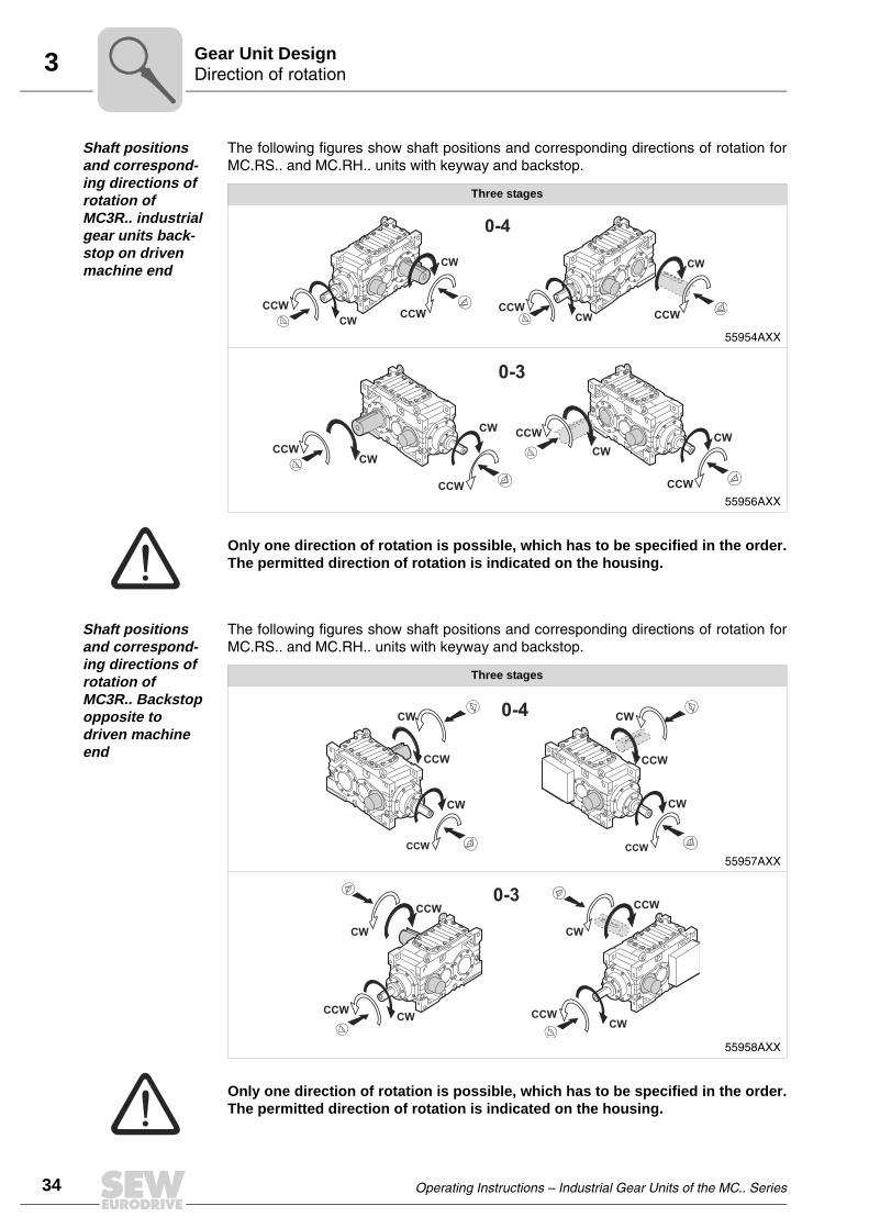
34
3 irection of rotationear Unit Design
Shaft positions and correspond-ing directions of rotation of MC3R.. industrial gear units back-stop on driven machine end
The following figures show shaft positions and corresponding directions of rotation forMC.RS.. and MC.RH.. units with keyway and backstop.
Shaft positions and correspond-ing directions of rotation of MC3R.. Backstop opposite to driven machine end
The following figures show shaft positions and corresponding directions of rotation forMC.RS.. and MC.RH.. units with keyway and backstop.
Three stages
55954AXX
55956AXX
0-4
CW CW
CWCW
CCWCCW
CCWCCW
0-3
CWCW
CWCWCCW
CCW
CCW
CCW
Only one direction of rotation is possible, which has to be specified in the order.The permitted direction of rotation is indicated on the housing.
Three stages
55957AXX
55958AXX
0-4
CW
CW
CCW
CW
CCW
CCW CCW
CW
0-3
CW
CCW
CW
CCW
CW
CCW CCW
CW
Only one direction of rotation is possible, which has to be specified in the order.The permitted direction of rotation is indicated on the housing.
DG
Operating Instructions – Industrial Gear Units of the MC.. Series

3Lubrication of industrial gear unitsGear Unit Design
3.9 Lubrication of industrial gear units
Depending on the mounting position, the lubrication types "splash lubrication" or"bath lubrication" are used for industrial gear units of the MC.. series.
Splash lubrication
Splash lubrication is used for industrial gear units of the MC.. series in horizontalmounting position (unit designation MC..L..). With splash lubrication, the oil level is low.With this lubrication method, oil is splashed onto the bearings and gearing components.
Oil bath lubrication
Oil bath lubrication is used for industrial gear units of the MC.. series in horizontalmounting position (unit designation MC..V..) and upright mounting position (unit desig-nation MC..E..) With oil bath lubrication, the oil level is so high that the bearings andgearing components are completely submerged in the lubricant.
Oil expansion tanks are always used for industrial gear units of the MC.PV.., MC.RV..and MC.RE.. series with oil bath lubrication. Oil expansion tanks allow the lubricantto expand when the gear unit heats up during operation.
Disregarding the mounting position, a steel oil expansion tank is used when the unitis installed outdoors and when the ambient conditions are very humid. This tank can beused both for the version with solid shaft and hollow shaft. A membrane in the oil expan-sion tank separates the oil in the gear unit from the humid ambient air and thus ensuresthat no humidity can build up in the gear unit.
Symbols used The following table shows which symbols are used in the subsequent figures and whatthey mean.
Symbol Meaning
Breather plug
Inspection opening
Oil dipstick
Oil drain plug
Oil filling plug
Oil sight glass
Air outlet screw
Operating Instructions – Industrial Gear Units of the MC.. Series
35
36
3 ubrication of industrial gear unitsear Unit Design
Oil bath lubrication upright mounting position
The steel oil expansion tank [6] is used for industrial gear units of the MC series inupright mounting position (unit designation MC.PE.. or MC..RE..).
51586AXXFigure 13: MC.PE../MC.RE.. industrial gear units with steel oil expansion tank
[1] Breather [4] Oil sight glass
[2] Oil dipstick [5] Air outlet screw
[3] Oil drain plug [6] Steel oil expansion tank
[4]
[5]
[6]
[1][2]
[3]
LG
Operating Instructions – Industrial Gear Units of the MC.. Series

3Lubrication of industrial gear unitsGear Unit Design
Oil bath lubrication vertical mount-ing position
The steel oil expansion tank [6] for industrial gear units of the MC series in verticalmounting position (unit designation MC.PV.. / MC.RV..) is located on the side of theassembly cover.
In dry environmental conditions, a cast iron oil expansion tank [1] is used. This oilexpansion tank is only used for the vertical mounting position with the solid outputshaft pointing downwards (unit designation MC.PVSF.. or MC.RVSF..).
51588AXXFigure 14: MC.PV../MC.RV.. industrial gear unit with steel oil expansion tank
[1] Breather [4] Oil sight glass
[2] Oil dipstick [5] Air outlet screw
[3] Oil drain plug [6] Steel oil expansion tank
51589AXXFigure 15: MC.PVSF../MC.RVSF.. industrial gear unit with cast iron oil expansion tank
[1] Cast iron oil expansion tank [3] Oil dipstick
[2] Breather plug [4] Oil drain plug
[2] [6] [4] [1] [5]
[3]
[1][3]
[2]
[4]
Operating Instructions – Industrial Gear Units of the MC.. Series
37
38
3 ubrication of industrial gear unitsear Unit Design
Pressure lubrication
If requested, pressure lubrication is possible as lubrication method disregarding themounting position.
With pressure lubrication, the oil level is low. For sizes 04 to 09, the gearing componentsand bearings not submerged in the oil bath are lubricated through a shaft end pump (→Sec. "Shaft end pump"), or, with sizes 02 to 09, through a motor pump (" Sec. → Motorpump").
The lubrication method "pressure lubrication" is used when
• oil bath lubrication is not desired for upright or vertical mounting positions
• input speeds are very high
• the gear unit must be cooled by an external oil/water (→ Sec. "Oil/water coolingsystem") or oil/air cooling system (→ Sec. "Oil/air cooling system")
For more details on oil expansion tanks, refer to Sec. "Mounting Positions".
LG
Operating Instructions – Industrial Gear Units of the MC.. Series

4Required tools / resourcesMechanical Installation
4 Mechanical Installation4.1 Required tools / resources
Not included in the scope of delivery:
• Wrench set
• Torque wrench (for shrink discs)
• Motor attachment to motor adapter
• Mounting device
• Shims and spacing rings if necessary
• Fasteners for input and output elements
• Lubricant (e.g. NOCO® fluid from SEW-EURODRIVE)
• For hollow shaft gear units (→ Sec. "Mounting/removal of hollow shaft gear units withkeyed connection): Threaded rod, nut (DIN 934), retaining screw, ejector screw
• Securing components according to Sec. "Gear unit foundation"
Installation tolerances
4.2 Before you begin
The drive may only be installed if
• the data on the nameplate of the motor match the supply voltage
• the drive is not damaged (no damage resulting from transport or storage) and
• the following requirements have been properly met:
– with standard gear units:ambient temperature according to the lubricant table in Sec. "Lubricants" (seestandard), no oil, acid, gas, vapors, radiation, etc.
– with special versions:drive configured in accordance with the ambient conditions (→ order documents)
4.3 Preliminary work
Output shafts and flange surfaces must be completely free of anti-corrosion agents,contamination or other impurities (use a commercially available solvent). Do not let thesolvent get in contact with the sealing lips of the oil seals:danger of damage to thematerial!
Shaft end Flanges
Diametric tolerance in accordance with DIN 748• ISO k6 for solid shafts with ∅ ≤ 50 mm• ISO m6 for solid shafts with ∅ > 50 mm• ISO H7 for hollow shafts for shrink disc• ISO H8 for hollow shafts with keyway• Center hole in accordance with DIN 332, shape DS..
Centering shoulder tolerance:• ISO js7 / H8
Operating Instructions – Industrial Gear Units of the MC.. Series
39
40
4 ear unit foundationechanical Installation
4.4 Gear unit foundation
Foundation for foot-mounted gear units
To ensure quick and successful mounting, the type of foundation should be correctlyselected and the mounting carefully planned in advance. Foundation drawings with allnecessary construction and dimension details should be available.
SEW-EURODRIVE recommends foundation methods shown in the following figures. Acustomer’s own foundation method must be equally adequate.
When mounting a gear unit onto steel framework, special attention should be paid to therigidity of this framework to prevent destructive vibrations and oscillations. The founda-tion must be dimensioned according to weight and torque of the gear unit by taking intoaccount the forces acting on the gear unit.
Example 1
Pos. "A" → Sec. "Concrete base"
51403AXXFigure 16: Reinforced concrete foundation for MC.PL.. / MC.RL.. industrial gear units
[1] Hex head screw or stud
[2] Hex nut if [1] is a stud or an upside-down screw
[3] Shims (about 3 mm space for shims)
[4] Hex nut
[5] Foundation bracket
[6] Hex nut
[7] Hex nut and foundation screw
[9] Supporting girder
[1]
[2]
[3]
[4][5]
[7]
[6]
[9]
A A
GM
Operating Instructions – Industrial Gear Units of the MC.. Series

4Gear unit foundationMechanical Installation
Example 2
Pos. "A" → Sec. "Concrete base"
51406AXXFigure 17: Reinforced concrete foundation for MC.PE.. / MC.RE.. industrial gear units
[1] Hex head screw or stud
[2] Hex nut if [1] is a stud or an upside-down screw
[3] Shims (about 3 mm space for shims)
[4] Hex nut
[5] Foundation bracket
[6] Hex nut
[7] Hex nut and foundation screw
[9] Supporting girder
[1]
[2]
[3]
[4][5]
[7]
[9]
[6]
A A
Operating Instructions – Industrial Gear Units of the MC.. Series
41
42
4 ear unit foundationechanical Installation
Example 3
Pos. "A" → Sec. "Concrete base"
51413AXXFigure 18: Reinforced concrete foundation for MC.PV.. / MC.RV.. industrial gear units
[1][2]
[3][4]
[5]
[7]
[9]
[6]
�40 mm�40 mm
A A
[10][10]
[1] Hex head screw or stud
[2] Hex nut if [1] is a stud or an upside-down screw
[3] Shims (about 3 mm space for shims)
[4] Hex nut
[5] Foundation bracket
[6] Hex nut
[7] Hex nut and foundation screw
[9] Supporting girder
[10] Shaft end pump (optional)
Important for MC.PV.. / MC.RV.. gear unit types:
• The mounting clearance between bearing cover and gear unit foundation mustbe at least 40 mm.
• The mounting clearance must be dimensioned adequately if the gear unit isequipped with a shaft end pump [10] (→ Sec. "Shaft end pump")
GM
Operating Instructions – Industrial Gear Units of the MC.. Series

4Gear unit foundationMechanical Installation
Concrete base The concrete base for the gear unit must be reinforced and interlocked with the concreteusing steel clamps, steel rods or steel elements. Only the supporting girders areembedded in the concrete (Pos. "A" → following figure).
51404AXXFigure 19: Reinforcing the concrete base (Pos. "A")
[1] Hex head screw or stud
[2] Hex nut if [1] is a stud or an upside-down screw
[3] Shims (about 3 mm space for shims)
[4] Hex nut
[5] Foundation bracket
[6] Hex nut
[7] Hex nut and foundation screw
[8] Weld seam
[9] Supporting girder
ØTB
A
KG
8 8 [8][8]L
s
S
ØTM
Ød
C
m
B
P
P
U
A
[1]
[2]
[3]
[4]
[5]
[7]
[9]
[6]
Operating Instructions – Industrial Gear Units of the MC.. Series
43
44
4 ear unit foundationechanical Installation
Dimensions
Grouting The density of the grout must be equal to that of the base concrete. The grout isconnected with the concrete base using concrete reinforcement steel.
Before welding the weld seams [9], ensure that
• the concrete base around the supporting girder has dried
• the gear unit with all mount-on components has been aligned to its final position
Tightening torques
Gear unit size
Stud Foundation frame Foundation screws
Supporting girders
∅TB ∅TM KG m P U A S ∅ d L P B C s
[mm]
02M20 24 28
3 120
120
120
20 M24 120
120
100 1003
04M24 28 34
05
06M30 33 40
150 30 M30 150 140 1207
08M36 39 52
09
The minimum tensile strength of the supporting girders and foundation screws must beat least 350 N/mm2.
Screw / nutTightening torque screw / nut
[Nm]
M8 19
M10 38
M12 67
M16 160
M20 315
M24 540
M30 1090
M36 1900
GM
Operating Instructions – Industrial Gear Units of the MC.. Series

4Gear unit foundationMechanical Installation
Counterflange for flange mounted gear units
Gear units can be supplied with a mounting flange on the LSS. Dependent on the bear-ing configuration, the two flange types are called
• "Mounting flange"
• "EBD-Mounting flange"
Basically, both flange types are possible for all gear unit designs and mounting posi-tions:
• MC.L..
• MC.V..
• MC.E..
Mounting flange
EBD-Mounting flange
Solid shaft LSS Hollow shaft LSS
56611AXXFigure 20: Mounting flange
Solid shaft LSS Hollow shaft LSS
56609AXXFigure 21: EBD-Mounting flange
Operating Instructions – Industrial Gear Units of the MC.. Series
45
46
4 ear unit foundationechanical Installation
The counterflange must have following characteristics:
• Stiff and torsionally rigid, taking into consideration
– gear unit weight– motor weight– the torque that has to be transmitted – additional forces acting on the gear unit from the customer machine (e.g. axial
forces from and towards gear unit from a mixing process)
• Horizontal
• Plain
• Vibration isolating, that means no vibrations are to be transmitted from close-by ma-chines and elements
• Not creating resonance vibrations
• A bore with H7-fitting suiting to the centering shoulder of the gear unit flange accord-ing to dimension drawing
The alignment of the gear unit LSS in relation to the counterflange has to be as accurateas possible This has an effect on the lifetime of bearing, shafts and coupling.
Allowable misalignments for the coupling on the LSS can be seen in chapter 5.2 or in aseparate coupling manual.
Following bolts of the 8.8-class should be used (Tensile strength 640 N/mm2)
The mounting surface of mounting flange and counter flange must be absolutelyfree of grease or oil and from other contamination (e.g. small textile particles,dust,….)
Gear unit sizeMounting flange EBD-Mounting flange
MC..
02 8 x M16 16 x M16
03 8 x M16 16 x M16
04 8 x M16 16 x M16
05 8 x M20 16 x M16
06 8 x M20 16 x M20
07 8 x M20 16 x M20
08 8 x M24 16 x M24
09 8 x M24 16 x M24
GM
Operating Instructions – Industrial Gear Units of the MC.. Series

4Mounting of solid shaft gear unitsMechanical Installation
4.5 Mounting of solid shaft gear units
Mount the gear unit in the following order:
1. Mount the components according to Sec. "Gear unit foundation". The shims [3]facilitate later adjustment and, if necessary, to mount a replacement gear unit.
2. Secure the gear unit at the selected positions on the supporting girders using threefoundation screws. Position the foundation screws at maximum possible distance(two screws on one side of the gear unit and one on the other side). Align the gearunit as follows:
– vertically by lifting, lowering or tilting the unit using the nuts of the foundationscrews
– horizontally by tapping the foundation screws slightly into the required direction
3. After having aligned the gear unit, tighten the three nuts of the foundation screwsused for alignment. Carefully insert the fourth foundation screw into the supportinggirder and tighten it securely. When doing so, make sure that the position of the gearunit does not change. If necessary, realign the gear unit.
4. Tack-weld the ends of the foundation screws to the supporting girders (at least threewelding spots per foundation screw). Tack-weld the foundation screws alternately inboth directions (starting from the middle) on each side of the center line of the gearunit. This way, misalignment caused by the welding process is avoided. After havingtack-welded all screws, they must be welded all the way round in the abovementioned order. Adjust the nuts on the foundation screws to ensure that the weldedfoundation screws do not twist the gear unit housing.
5. After having tack-welded the nuts of the retaining screws of the gear unit, check themounting and carry out grouting.
6. When the grouting concrete has set, check the mounting a last time and adjust, ifnecessary.
Before mounting the gear unit, check the foundation dimensions with those in thecorresponding drawings in Sec. "Gear unit foundation."
Operating Instructions – Industrial Gear Units of the MC.. Series
47
48
4 ounting of solid shaft gear unitsechanical Installation
Mounting accuracy when aligning
When aligning the gear unit, make sure that the mounting tolerances for the evennessof the foundation are not exceeded (values ymax in below table). If necessary, use shims[3] to align the gear unit on the foundation plate.
Flange mounted gear units
Mount the gear unit in the following order:
1. Lower the gear unit on the counterflange with suitable lifting means. Especially takecare of the guidelines mentioned in Sec. 2.1.
2. Secure the gear unit at the right position on the counterflange using the flange boltsand tighten them crosswise with the full tightening torque (→ sec. 4.4).
51590AXXFigure 22: Mounting tolerances of the foundation
JE[mm]
ymax[mm]
< 400 0.035
400 ... 799 0.060
800 ... 1200 0.090
1200 ... 1600 0.125
JE JE
Y Y
[3]
Before mounting the gear unit, check if the counterflange fullfils the requirementsmentioned in Sec. "4.4 Gear unit foundation - Counterflange for flange mountedgear units"
MM
Operating Instructions – Industrial Gear Units of the MC.. Series

4Mounting / removing hollow shaft gear units with keyed connectionMechanical Installation
4.6 Mounting / removing hollow shaft gear units with keyed connection
Selecting the adequate thread and length of the threaded rod as well as the retainingscrew depends on the design of the customer’s machine.
Thread sizes SEW-EURODRIVE recommends the following thread sizes:
The thread size of the ejector screw depends on the end plate [4]:
Mounting the hollow shaft gear unit onto the customer’s shaft
• To mount and secure the gear unit, attach the circlips [3] and the end plate [4] on thehollow shaft bore.
• Included in the scope of delivery (→ Figure 23):
– Circlips [3], end plate [4]
• Not included in the scope of delivery (→ Figure 23 / Figure 24 / Figure 25):
– Threaded rod [2], nut [5], retaining screw [6], ejector screw [8]
Gear unit size
Thread size for• threaded rod [2]• nut (DIN 934) [5]
• retaining screw [6]
02 - 06 M24
07 - 09 M30
Gear unit size Thread size of ejector screw [8]
02 - 06 M30
07 - 09 M36
56813AXXFigure 23: Mounting of hollow shaft gear unit with keyed connection
[1] Customer’s shaft [5] Nut
[2] Threaded rod [7] Hollow shaft
[3] Circlips [8] Bushing
[4] End plate
[1][7][8] [2] [3] [4]
[5]
Operating Instructions – Industrial Gear Units of the MC.. Series
49
50
4 ounting / removing hollow shaft gear units with keyed connectionechanical Installation
• Apply NOCO® fluid to the hollow shaft [7] and the shaft end of the customer’s shaft[1].
• Push the gear unit onto the customer’s shaft [1]. Thread the threaded rod [2] into thecustomer’s shaft [1]. Tighten the customer’s shaft [1] with the nut [5] until the shaftend of the customer’s shaft [1] and the end plate [4] meet.
• Loosen the nut [5] and unscrew the threaded rod [2]. After having mounted the gearunit, secure the customer’s shaft [1] using the retaining screw [6].
Removing the hollow shaft gear unit from the customer’s shaft
• Remove the retaining screw [Figure 24, Pos. 6].
• Remove the outer circlip [3] and the end plate [4].
• Thread the retaining screw [6] into the customer’s shaft [1].
• Flip the end plate [4] and remount the end plate and the outer circlip [3].
• Thread the ejector screw [8] into the end plate [4] to remove the gear unit from thecustomer’s shaft [1].
56814AXXFigure 24: Mounted hollow shaft gear unit with keyed connection
[6]
56815AXXFigure 25: Removing hollow shaft gear unit with keyed connection
[1] Customer’s shaft [6] Retaining screw
[3] Circlips [8] Ejector screw
[4] End plate
[6][1] [3] [4]
[8]
MM
Operating Instructions – Industrial Gear Units of the MC.. Series

4Mounting / removing hollow shaft gear units with shrink discMechanical Installation
4.7 Mounting / removing hollow shaft gear units with shrink disc
A shrink disc serves as connecting element between the hollow shaft of the gear unitand the customer’s shaft. For the shrink disc type used (designation: RLK608), refer tosection "Identifying shrink disc type"
Selecting the appropriate thread and length of the threaded rod as well as the retainingscrew depends on the design of the customer’s machine.
Thread sizes SEW-EURODRIVE recommends the following thread sizes:
The thread size of the ejector screw depends on the end plate [4]:
Identifying shrink disc type
Normally, the shrink disc type RLK608 is used. It has a metallic colour shade. The letters"RLK 608-…" are engraved:
• Included in the scope of delivery (→ Figure 31):
– Circlip [3], end plate [4]
• Not included in the scope of delivery (→ Figure 31 / Figure 32 / Figure 35):
– Threaded rod [2], nut [5], retaining screw [6], ejector screw [8]
Gear unit size
Thread size for • threaded rod [2]• nut (DIN 934) [5]• retaining screw [6]
→ Figure 32, 33
02 - 06 M24M3007 - 09
Gear unit size Thread size of the ejector screw [8]
02 - 06 M30
07 - 09 M36
56612AXXFigure 26: shrink disc type RLK608
[10] Locking screw
[11] Forcing thread
[10]
[11]
Order-specific, other shrink disc types could be used. In this case please refer to theseparate, shrink disc-specific manual.
Operating Instructions – Industrial Gear Units of the MC.. Series
51
52
4 ounting / removing hollow shaft gear units with shrink discechanical Installation
Mounting the shrink disc
• Do not tighten the locking screws [10] before the customer’s shaft [1] has beenmounted, else the hollow shaft could be deformed!
• Slide the shrink disc [9] with untightened screws onto the hub of the hollow shaftbore. Position the customer’s shaft [1] in the hollow shaft bore. Next move the shrinkdisc [9] by dimension A (→ following figure, Sec. "Dimension A") from the shaft endof the hollow shaft:
Dimension A
56817AXXFigure 27: Shrink disc locking screws before customer’s shaft mounting
51986AXXFigure 28: Mounting the shrink disc
[1] Customer’s shaft [10] Locking screws
[9] Shrink disc
A
A
[1]
[10]
[9]
It is essential to make sure that the clamping area of the shrink disc is free fromgrease.
Gear unit size Shrink disc type RLK608Dimension A [mm]MC..
02 39
03 45
04 44
05 42
06 44
07 50
08 51
09 49
MM
Operating Instructions – Industrial Gear Units of the MC.. Series

4Mounting / removing hollow shaft gear units with shrink discMechanical Installation
Mounting the hollow shaft gear unit onto the customer’s shaft
• Before mounting the gear unit, degrease the hollow shaft bore and the customer’sshaft [1].
• Apply a small amount of NOCO® fluid on the customer’s shaft to the area of the bush-ing [11].
56820AXXFigure 29: Degrease of hollow shaft bore and customer‘s shaft
56811AXXFigure 30: Application of NOCO® fluid on customer’s shaft
[1]
[7][7]
[7]
[11]
[1]
Never apply NOCO® fluid directly to the bushing as the paste may be able to getinto the clamping area of the shrink disk when the input shaft is put on.
Operating Instructions – Industrial Gear Units of the MC.. Series
53
54
4 ounting / removing hollow shaft gear units with shrink discechanical Installation
• To mount and secure the gear unit, attach the circlips [3] and the end plate [4] on thehollow shaft bore.
• Push the gear unit onto the customer’s shaft [1]. Thread the threaded rod [2] into thecustomer’s shaft [1]. Tighten the customer’s shaft [1] with the nut [5] until the shaftend of the customer’s shaft [1] and the end plate [4] meet.
• Loosen the nut [5] and unscrew the threaded rod [2]. After having mounted the gearunit, secure the customer’s shaft [1] using the retaining screw [6].
56816AXXFigure 31: Mounting of hollow shaft gear unit with shrink disc
[1] Customer’s shaft [7] Hollow shaft
[2] Threaded rod [9] Shrink disc
[3] Circlip [10] Locking screws
[4] End plate [11] Bushing
[5] Nut
56817AXXFigure 32: Mounted hollow shaft gear unit with shrink disc, shrink disc unclamped
[1][7][11] [2] [9] [10] [3] [4]
[5]
[10]
[6]
MM
Operating Instructions – Industrial Gear Units of the MC.. Series
4Mounting / removing hollow shaft gear units with shrink discMechanical Installation
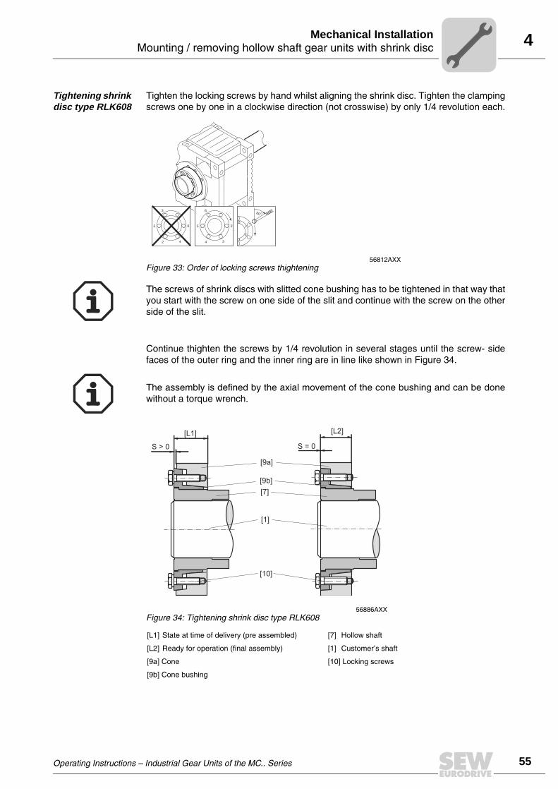
Tightening shrink disc type RLK608
Tighten the locking screws by hand whilst aligning the shrink disc. Tighten the clampingscrews one by one in a clockwise direction (not crosswise) by only 1/4 revolution each.
Continue thighten the screws by 1/4 revolution in several stages until the screw- sidefaces of the outer ring and the inner ring are in line like shown in Figure 34.
56812AXXFigure 33: Order of locking screws thightening
The screws of shrink discs with slitted cone bushing has to be tightened in that way thatyou start with the screw on one side of the slit and continue with the screw on the otherside of the slit.
The assembly is defined by the axial movement of the cone bushing and can be donewithout a torque wrench.
56886AXXFigure 34: Tightening shrink disc type RLK608
[L1] State at time of delivery (pre assembled) [7] Hollow shaft
[L2] Ready for operation (final assembly) [1] Customer’s shaft
[9a] Cone [10] Locking screws
[9b] Cone bushing
S > 0
[9a]
[L1]
[10]
S = 0
[L2]
[9b]
[7]
[1]
Operating Instructions – Industrial Gear Units of the MC.. Series
55
56
4 ounting / removing hollow shaft gear units with shrink discechanical Installation
Removing the shrink disc
Loosen the locking screws [10] by 1/4 revolution each in sequence in several levelsevenly, so that tilting of the clamping surface is avoided.
If the cone bushing and cone ring do not loosen from each other by themselves:
Take the required quantity of locking screws and bolt them evenly into the removingthread bores. Tighten the locking screws in several levels until the cone bushing is sep-arated from the cone ring.
Take the shrink disc off from the hollow shaft.
Removing the hollow shaft gear unit from the customer’s shaft
• Remove the retaining screw [Figure 32, Pos. 6].
• Remove the outer circlip [3] and the end plate [4].
• Thread the retaining screw [6] into the customer’s shaft [1].
• Flip the end plate [4] and remount the end plate and the outer circlip [3].
• Thread the ejector screw [8] into the end plate [4] to remove the gear unit from thecustomer’s shaft [1].
Cleaning and lubrication
Clean the shrink disk after the disassembly and
• grease afterwards the locking srews [10] on the thread and under the head with pastewhich consist MoS2, e.g. "gleitmo 100" from FUCHS LUBRITECH (www.fuchs.-lu-britech.de).
• Coat the conical surfaces and the screw-side face of the cone bushing with a thin film(0.01 ... 0.02 mm) with the solid film lubricant "gleitmo 900" from FUCHSLUBRITECH (www.fuchs.-lubritech.de) or with an equal product from other supplier.
Never unscrew the locking screws completely from the tapped hole, since other-wise danger of accident exists.
56818AXXFigure 35: Removing the hollow shaft gear unit with shrink disc connection
[1] Customer’s shaft [6] Retaining screw
[3] Circlip [8] Ejector screw
[4] End plate
[6][1] [3] [4]
[8]
Spray the solid film lubricant on the surface till the color of the solid film lubricant is justthick enough to cover the surface (in this case the thickness will be about 0.01 ... 0.02mm)
MM
Operating Instructions – Industrial Gear Units of the MC.. Series

4Mounting a motor with motor adapterMechanical Installation
4.8 Mounting a motor with motor adapter
Motor adapters [1] are available for mounting IEC motors of sizes 132 to 315 to industrialgear units of the MC series.
51594AXXFigure 36: Motor adapter for MC.P.. industrial gear units
[1] Motor adapter
[2] Coupling
51593AXXFigure 37: Motor adapter for MC.R.. industrial gear units
[1] Motor adapter
[2] Coupling
[1]
[2]
[1] [2]
For mounting couplings [2], refer to the notes in Sec. "Mounting of couplings."
Operating Instructions – Industrial Gear Units of the MC.. Series
57
58
4 ounting a motor with motor adapterechanical Installation
The following applies to all tables:
When selecting a motor, take into account the permitted motor weight, the gear unitdesign and the type of gear unit mounting according to the following tables.
GM = Motor weight GG = Gear unit weight
Mounting type
Series / industrial gear unit design
MC.PL.. MC.RL..
Foot-mounted GM ≤ GG GM ≤ GG
Shaft-mounted GM ≤ 0.5GG GM ≤ GG
Flange-mounted GM ≤ 0.5GG GM ≤ GG
Mounting type
Series / industrial gear unit design
MC.PV..
MC.RV..
Foot-mounted GM ≤ 1.5GG GM ≤ GG
Shaft-mounted GM ≤ GG GM ≤ GG
Flange-mounted GM ≤ GG GM ≤ 0.75GG
Mounting type
Series / industrial gear unit design
MC.PE..
MC.RE..
Foot-mounted GM ≤ GG GM ≤ 1.5GG
Shaft-mounted GM ≤ GG GM ≤ GG
Flange-mounted GM ≤ GG GM ≤ GG
These tables are only valid for stationary operation. If gear unit is moving during(e.g. travel drives) please contact SEW-EURODRIVE.
MM
Operating Instructions – Industrial Gear Units of the MC.. Series
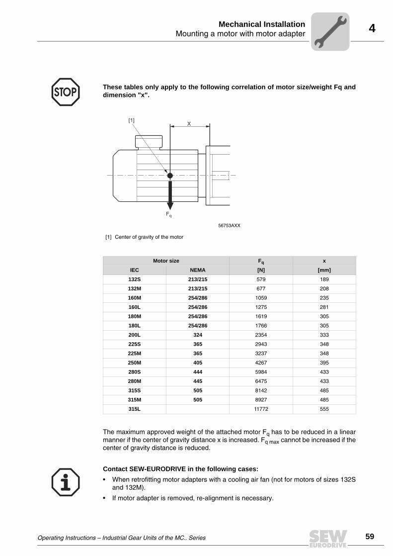
4Mounting a motor with motor adapterMechanical Installation
The maximum approved weight of the attached motor Fq has to be reduced in a linearmanner if the center of gravity distance x is increased. Fq max cannot be increased if thecenter of gravity distance is reduced.
These tables only apply to the following correlation of motor size/weight Fq anddimension "x".
56753AXX
[1] Center of gravity of the motor
Motor size Fq x
IEC NEMA [N] [mm]
132S 213/215 579 189
132M 213/215 677 208
160M 254/286 1059 235
160L 254/286 1275 281
180M 254/286 1619 305
180L 254/286 1766 305
200L 324 2354 333
225S 365 2943 348
225M 365 3237 348
250M 405 4267 395
280S 444 5984 433
280M 445 6475 433
315S 505 8142 485
315M 505 8927 485
315L 11772 555
X
Fq
[1]
Contact SEW-EURODRIVE in the following cases:
• When retrofitting motor adapters with a cooling air fan (not for motors of sizes 132Sand 132M).
• If motor adapter is removed, re-alignment is necessary.
Operating Instructions – Industrial Gear Units of the MC.. Series
59
60
5 mportant installation instructionsechanical Installation Options
5 Mechanical Installation Options5.1 Important installation instructions
Important installation notes
• Only use a mounting device for installing input and output elements. Use the centerbore and the thread on the shaft end for positioning purposes.
• Power transmission elements should be balanced after insertion and must not giverise to any impermissible radial or axial forces.
Adjust the following misalignments when mounting couplings:
a) Axial misalignment (maximum and minimum clearance)
b) Offset misalignment (concentric running fault)
c) Angular misalignment
Disconnect the motor from the power supply before starting work and secure itagainst unintentional restart!
• Never mount couplings, pinions, etc. onto the shaft end by hitting them with ahammer (damage to bearings, housing and the shaft!).
• Observe correct tension of the belt for belt pulleys (in accordance withmanufacturer’s specifications).
Note:
Installation is easier if you first apply lubricant to the output element or heat it up briefly(to 80-100°C).
03356AXXFigure 38: Clearance and misalignment when mounting the coupling
a) b) c)
Input and output elements such as couplings must be equipped with a protectioncover!
IM
Operating Instructions – Industrial Gear Units of the MC.. Series

5Important installation instructionsMechanical Installation Options
Measuring of angular misalign-ment with a feeler gauge
The following figure shows the measurement for angular misalignment (α) using a feelergauge. When using this method, an accurate result is only achieved when the deviationof the coupling faces is eliminated by turning both coupling halves by 180° and theaverage value is then calculated from the difference (a1– a2).
Measuring of angular misalign-ment using a micrometer dial
The following figure shows the measurement for angular misalignment using amicrometer dial. This measuring method provides the same result as described under"Measuring angular offset with a feeler gauge" if the coupling halves are rotatedtogether, for instance with one coupling pin, so that the needle of the micrometer dialdoes not move noticeably on the measuring surface.
A prerequisite for this measuring method is that there is no axial play in the shaftbearings when the shafts rotate. If this condition is not fulfilled, the axial play betweenthe faces of the coupling halves must be eliminated. As an alternative, you can use twomicrometer dials positioned on the opposite sides of the coupling (to calculate thedifference of the two micrometer dials when rotating the coupling).
Note:
The following methods for measuring angular and axial misalignment areimportant for complying with the mounting tolerances specified in Sec."Mounting of couplings"!
52063AXXFigure 39: Measuring angular misalignment using a feeler gauge
a1
a2
a
Dα
52064AXXFigure 40: Measuring angular misalignment using a micrometer dial
a1
a2
a
Dα
f2 f1
Operating Instructions – Industrial Gear Units of the MC.. Series
61
62
5 mportant installation instructionsechanical Installation Options
Measuring of offset misalign-ment using straight-edge and micrometer dial
The following figure shows the measurement for offset misalignment using a straight-edge. Permissible values for eccentricity are usually so small that the best measurementresults can be achieved with a micrometer dial. If you rotate one coupling half togetherwith the micrometer dial and divide the deviation by two, the micrometer dial will indicatethe deviation and as a result the misalignment (dimension "b"), which includes the offsetmisalignment of the other coupling half.
Measuring of offset misalign-ment using a micrometer dial
The following figure shows the measurement for offset misalignment using a moreaccurate measuring method. The coupling halves are rotated together without thetip of the micrometer dial moving on the measuring surface. The offset misalignment isobtained by dividing the deviation indicated on the micrometer dial (dimension "b").
52065AXXFigure 41: Measuring offset misalignment using straight-edge and micrometer dial
b
f2 f1
52066AXXFigure 42: Measuring offset misalignment using a micrometer dial
b
f2 f1
IM
Operating Instructions – Industrial Gear Units of the MC.. Series

5Mounting of couplingsMechanical Installation Options
5.2 Mounting of couplings
ROTEX coupling
The low-maintenance, elastic ROTEX coupling is capable of compensating radial andangular misalignment. Careful and exact alignment of the shaft ensures long service lifeof the coupling.
51663AXXFigure 43: Design of the ROTEX coupling
[1] Coupling hub
[2] Ring gear
[1]
[1]
[2]
Operating Instructions – Industrial Gear Units of the MC.. Series
63
64
5 ounting of couplingsechanical Installation Options
Mounting the coupling halves onto the shaft
51689AXXFigure 44: Mounting dimensions of the ROTEX coupling
s s
G
E
L1
Ød H
Ød W
Coupling size
Mounting dimensions Locking screw
E[mm]
s[mm]
dH[mm]
dW[mm]
L1 (Alu / GG / GGG)[mm]
L1 (steel)[mm]
G Tightening torque[Nm]
14 13 1.5 10 7 - - M4 2.4
19 16 2 18 12 26 - M5 4.8
24 18 2 27 20 30 - M5 4.8
28 20 2.5 30 22 34 - M6 8.3
38 24 3 38 28 40 60 M8 20
42 26 3 46 36 46 70 M8 20
48 28 3.5 51 40 50 76 M8 20
55 30 4 60 48 56 86 M10 40
65 35 4.5 68 55 63 91 M10 40
75 40 5 80 65 72 104 M10 40
90 45 5.5 100 80 83 121 M12 69
100 50 6 113 95 92 - M12 69
110 55 6.5 127 100 103 - M16 195
125 60 7 147 120 116 - M16 195
140 65 7.5 165 135 127 - M20 201
160 75 9 190 160 145 - M20 201
180 85 10.5 220 185 163 - M20 201
The shaft distance must be strictly observed (dimension E) to ensure axial play ofthe coupling.
MM
Operating Instructions – Industrial Gear Units of the MC.. Series

5Mounting of couplingsMechanical Installation Options
Mounting dimensions ROTEX coupling in motor adapter
Tighten the set screws (A) to avoid axial play of the coupling.
51696AXXFigure 45: Mounting dimensions of the ROTEX coupling at the HSS (input shaft) – motor adapter
L3
L2
E
L1A A
The mounting dimensions specified in the following table only apply to mounting aROTEX coupling in a motor adapter. They apply to all gear unit versions and gear ratios.
ROTEX coupling size
IEC motor size
Mounting dimensions
E[mm]
L1[mm]
L2[mm]
L3[mm]
R28/38 132 20 0 –17 3
R38/45 160 24 1 0 25
R42/55 180/200 26 –1 0 25
R48/60 225 28 0 –3 25
R55/70 225 30 0 –5 25
R65/75 250/280 35 0 –10 25
R75/90 315 40 0 –15 25
R90/100 315 45 –20 0 25
The shaft distance must be strictly observed (dimension E) to ensure axial play ofthe coupling.
Operating Instructions – Industrial Gear Units of the MC.. Series
65
66
5 ounting of couplingsechanical Installation Options
Nor-Mex coupling, types G and E
The low-maintenance Nor-Mex couplings types G and E are torsionally flexiblecouplings capable of compensating axial, angular, and radial shaft misalignments.Torque is transmitted via an elastic element with high damping properties, which is alsooil and heat resistant. The couplings can be used for either direction of rotation and canbe mounted in any position. The design of the Nor-Mex coupling type G allows to replacethe elastic element [5] without movement of the shafts.
51667AXXFigure 46: Design of the Nor-Mex E / Nor-Mex G coupling
[1] Coupling hub [1] Socket head screw
[2] Elastic element [2] Washer
[3] Claw ring
[4] Flange hub
[5] Elastic element
[6] Coupling hub
[3]
[1]
[4]
[5]
[6]
[2]
[2]
[1]
[1]
Nor-Mex E Nor-Mex G
MM
Operating Instructions – Industrial Gear Units of the MC.. Series

5Mounting of couplingsMechanical Installation Options
Mounting instructions, mounting dimen-sions for Nor-Mex G couplings
After having mounted the coupling halves, ensure that the recommended play(dimension S2 for type G, dimension S1 for type E) and the overall length (dimension LGfor type G and dimension LE for type E) corresponds with the dimensions given in thefollowing tables. Accurate alignment of the coupling (→ Sec. 'Mounting tolerances')ensures long service life.
51674AXXFigure 47: Mounting dimensions of the Nor-Mex G coupling
Nor-Mex GCoupling size
Mounting dimensions
lE[mm]
lG[mm]
LG[mm]
Permitted tolerance S2[mm]
Weight[kg]
82 40 40 92 12±1 1.85
97 50 49 113 14±1 3.8
112 60 58 133 15±1 5
128 70 68 154 16±1 7.9
148 80 78 176 18±1 12.3
168 90 87 198 21±1.5 18.3
194 100 97 221 24±1.5 26.7
214 110 107 243 26±2 35.5
240 120 117 267 30±2 45.6
265 140 137 310 33±2.5 65.7
295 150 147 334 37±2.5 83.9
330 160 156 356 40±2.5 125.5
370 180 176 399 43±2.5 177.2
415 200 196 441 45±2.5 249.2
480 220 220 485 45±2.5 352.9
575 240 240 525 45±2.5 517.2
IE IG
LG
S2
Operating Instructions – Industrial Gear Units of the MC.. Series
67
68
5 ounting of couplingsechanical Installation Options
Mounting dimensions of the Nor-Mex E coupling
51674AXXFigure 48: Mounting dimensions of the Nor-Mex E coupling
Nor-Mex ECoupling size
Mounting dimensions
lE[mm]
LE[mm]
Permitted tolerance S1[mm]
Weight[kg]
67 30 62.5 2.5± 0.5 0.93
82 40 83 3± 1 1.76
97 50 103 3± 1 3.46
112 60 123.5 3.5± 1 5
128 70 143.5 3.5± 1 7.9
148 80 163.5 3.5± 1.5 12.3
168 90 183.5 3.5± 1.5 18.4
194 100 203.5 3.5± 1.5 26.3
214 110 224 4± 2 35.7
240 120 244 4± 2 46.7
265 140 285.5 5.5± 2.5 66.3
295 150 308 8± 2.5 84.8
330 160 328 8± 2.5 121.3
370 180 368 8± 2.5 169.5
415 200 408 8± 2.5 237
480 220 448 8± 2.5 320
575 240 488 8± 2.5 457
IE IE
LE
S1
MM
Operating Instructions – Industrial Gear Units of the MC.. Series

5Mounting of couplingsMechanical Installation Options
Mounting dimensions of the Nor-Mex coupling type G in the motor adapter
Tighten the set screws (A) to avoid axial play of the coupling.
51672AXXFigure 49: Mounting dimensions of the Nor-Mex coupling on the HSS (input shaft) – motor adapter
L
L
L
S
AA
2
3
2
1
The mounting tolerances specified in the following table only apply to mounting a Nor-Mex coupling in a motor adapter.
NOR-MEX coupling size G.. 97 97 112 128 148 168 194 214
IEC motor size 132 160 160/180 200 225 250/280 280/315 315
Gear unit sizeGear ratio i
Mounting dimension
[mm]
AllAll
S2 14 14 15 16 18 21 24 26
L3 3 25 25 25 25 25 25 25
MC3R02i = 14 ... 63
L2 - 5 5 5 10 2 1 0
L1 - 6 5 4 –3 2 0 –1
MC3R05i = 14 ... 63
L2 - 5 5 5 4 2 5 0
L1 - 6 5 4 3 2 –4 –1
MC3R08i = 14 ... 63
L2 - 5 5 5 4 2 1 5
L1 - 6 5 4 3 2 1 –6
Other MC..i = 7.1 ... 112
L2 –5 5 5 5 4 2 1 0
L1 –6 6 5 4 3 2 0 –1
Operating Instructions – Industrial Gear Units of the MC.. Series
69
70
5 ounting of couplingsechanical Installation Options
Flexible jaw couplings MT, MS-MTN series
Mounting
1. Ensure that all parts are clean.
2. Apply a light coat of grease to the O-rings [6] and place them into the grooves of thesleeves [2,3 or 4,5].
3. Apply grease onto the sleeve teeth [2,3 or 4,5]. Place the sleeves onto the shaftswithout damaging the O-rings [6].
57599AEN
[9,8] [9,8] [13,14][1] [6] [6][3] [4] [5] [7]
[1]
[15,16]
[11] [11] [10][12] [17][2] [1][1]
Type X Type D
Standard type Type F Type FE MSC
[1] Coupling hub [7] Cover [13] Washer
[2] Sleeve [8] Grease nipple [14] Nut
[3] Sleeve [9] Grease nipple [15] Bolts
[4] Sleeve (male) [10] Gasket [16] Washer
[5] Sleeve (female) [11] Bolt [17] O-ring
[6] Seal or O-ring [12] Self-locking nut
MM
Operating Instructions – Industrial Gear Units of the MC.. Series

5Mounting of couplingsMechanical Installation Options
4. For couplings larger than the MS-325 or MT-260 types, you have to grease the O-rings or seals [6] before inserting them in the grooves of the cover [7]. Next, place thecovers [7] onto the shafts.
5. Install the hubs [1] on their respective shaft with the longest chamfer hub endtorwards the machine bearing (see detail A). Hub faces have to be flush with the shaftend.
6. Align the shafts to be connected with the coupling hubs and check the spacing "a"between the hubs (see detail B). Refer to the table on page 73) for the accordingvalues..
7. Align the two shafts. Check for correct alignment using a dial indicator. The alignmentprecision depends on the running speed.
8. Allow the hubs [1] to cool before tightening the sleeves [2, 3 or 4, 5) over the hubs.Before installing the sleeves [2, 3 or 4,5], apply grease onto the coupling hub teeth[1].
9. Install the O-ring [10] and thighten the steeves to the recommended thighteningtorque (see detail B). It is recommended to grease the O-ring. Make sure that theflange lubrication holes are positioned at an angle of 90° to each other.
Before installing the hubs [1], heat them but do not exceed 110 °C. Do not use anopen flame burner.
57602AEN
57604AEN
ADetail A
a
Ma
Detail B
Operating Instructions – Industrial Gear Units of the MC.. Series
71
72
5 ounting of couplingsechanical Installation Options
10.To fill the grease, remove both plugs [9] from the sleeve [2, 3 or 4, 5]. Next, proceedas follows:
Turn the coupling in such a way that the flange lubrication holes are in 1:30, 4:30,7:30, 10:30 o’clock positions if the coupling were seen as a clock face. Remove the1:30 and 7:30 position plugs [9] and pump grease into the 1:30 posizion holes untilgrease leaks out from the lower 7:30 position hole (see detail C). During this processit is recommended to remove the 10:30 position plug to vent the inside. For greasequality and more accurate quantity, → Section Recommended Lubrication andQuantily. If running conditions differ from those in → Section Recommended Lubri-cation and Quantity, consult SEW. For HAD, MTD, MSD, MTX, MTXL, MSXL, HAXL,MTCO and MSCO types, each coupling half must be lubricated separately. For MS-VS, MTV types, consult SEW.
Maintenace Every 3000 operating hours.
If longer intervals are required, contact SEW. Proceed as mentioned under 11.
Disassembly and condition check
Every 8000 operating hours or every 2 years.
1. Before moving the sleeves, clean the hub surfaces near the O-rings [6] free from rustor dirt.
2. Remove the bolts [11] and the O-ring [10].
3. Check the gearing and sealing.
4. Check for correct alignment.
57589AEN
45°
90°
130 A1030 B
730A 430
B
Detail C
inin
outout
MM
Operating Instructions – Industrial Gear Units of the MC.. Series

5Mounting of couplingsMechanical Installation Options
Mounting tolerance
57587ADE
Type BR Type ES Type VS Type CO
Type L Type FD Type FS Type S
57586AXX
a
Ma
MT, MS and MTN types
Size a [mm] Size a [mm] Size a [mm]
MT-MTN-42, MS-5 6±1 MT-MTN-205, MS-430 12±3 MT-460, MS-MN-5250 20±4
MT-MTN-55, MS-10 6±1 MT-MTN-230, MS-600 12±3 MT-500, MS-MN-6500 25±4
MT-MTN-70, MS-20 6±2 MT-MTN-260, MS-800 12±3 MT-550, MS-MN-9500 25±4
MT-MTN-90, MS-35 8±2 MT-280, MS-MN-1150 16±3 MT-590, MS-MN-11000 25±4
MT-MTN-100, MS-60 8±2 MT-310, MS-MN-1500 16±3 MT-620, MS-MN-13500 30±6
MT-MTN-125, MS-105 8±2 MT-345, MS-MN-2100 16±3 MT-650, MS-MN-17000 30±6
MT-MTN-145, MS-150 10±2 MT-370, MS-MN-2650 20±4 MT-680, MS-MN-19000 30±6
MT-MTN-165, MS-210 10±3 MT-390, MS-MN-3400 20±4 MT-730, MS-MN-22500 30±6
MT-MTN-185, MS-325 10±3 MT-420, MS-MN-4200 20±4 MT-800, MS-MN-27000 30±6
Operating Instructions – Industrial Gear Units of the MC.. Series
73
74
5 ounting of couplingsechanical Installation Options
MT and MS-MTN types
SizeSize
Tightening Torque MA [Nm]
SizeSize
Tightening Torque MA [Nm]
SizeSize
Tightening Torque MA [Nm]
MT-42 8 MT-205 325 MT-460, MS-MN-5250 760
MT-55 20 MT-230 325 MT-500, MS-MN-6500 1140
MT-70 68 MT-26 565 MT-550, MS-MN-9500 1140
MT-90 108 MT-280, MS-MN-1150 375 MT-590, MS-MN-11000 1140
MT-100 108 MT-310, MS-MN-1500 375 MT-620, MS-MN-13500 1800
MT-125 230 MT-345, MS-MN-2100 660 MT-650, MS-MN-17000 1800
MT-145 230 MT-370, MS-MN-2650 660 MT-680, MS-MN-19000 1800
MT-165 230 MT-390, MS-MN-3400 760 MT-730, MS-MN-22500 1800
MT-185 325 MT-420, MS-MN-4200 760 MT-800, MS-MN-27000 1800
MS-MTN types
SizeSize
Tightening Torque MA [Nm]Size
Size Tightening Torque MA [Nm]
MS-5, MTN-42 20 MS-150, MTN-145 108
MS-10, MTN-55 39 MS-210, MTN-165 108
MS-20, MTN-70 39 MS-325, MTN-185 325
MS-35, MTN-90 68 MS-430, MTN-205 325
MS-60, MTN-100 68 MS-600, MTN-230 325
MS-105, MTN-125 68 MS-800, MTN-260 375
MM
Operating Instructions – Industrial Gear Units of the MC.. Series

5Mounting of couplingsMechanical Installation Options
Recommended Lubricants and Quantity
Greases for operation between 0°C and 70°C.
The couplings are supplied with a protective grease only, which is not sufficient fornormal operation.
Before mounting the coupling, apply approx. 70 % of the grease quantity manuallybetween hub and sleeve teeth as well as to the surrounding area. After mounting, pressthe remaining 30 % of the grease into the flange lubrication holes.
Class NLGI 0 grease is recommended for speeds below 300 rpm and NLGI 00 for verylow speeds. In both cases, the greases must have good adherence. More frequentlubrication intervals than advised in this operating instructions are required for hightemperatures, low speeds, and reversing drives.
Company Oil
Normal operation conditions
Amoco Amoco coupling grease
Castrol Spheerol BN 1
Cepsa-Krafft KEP 1
Esso-Exxon Unirex RS 460, Pen-0- Led EP
Fina Ceran EP-0
Klüber Klüberplex GE 11-680
Mobil Mobilgrease XTC,Mobiltemp SHC 460 spezial
Shell Shell Albida GC1
Texaco Coupling grease KP 0/1 K-30
Verkol Verkol 320-1 Grado 1
Normal speed and heavy duty operation
Klüber Klüberplex GE 11-680
Texaco Coupling grease KP 0/1 K-30
HIGH SPEED1)
1) Circumferential speed > 80 m/s
Amoco Coupling grease
Esso-Exxon Unirex RS-460
Klüber Klüberplex GE 11-680
Mobil Mobilgrease XTC
Texaco Coupling grease KP 0/1 K-30
Operating Instructions – Industrial Gear Units of the MC.. Series
75
76
5 ounting of couplingsechanical Installation Options
For types MTD, MSD, HAD, MTX, MSX, HAX, MSXL, MTXL, MTBRX, MSBRX, MTSR-P, apply the given quantity divided by 2 to each coupling half. Example: MTX-125, 0.25kg for each half. For types MSS, MTS, MSC, MTCO, MSCO, MTES, vertical couplingsand disengaging couplings, consult our Technical Department
MT type
Size Quantity1) [kg] Size Quantity1) [kg] Size Quantity1) [kg]
MT-42 0.04 MT-205 2.20 MT-460 11.50
MT-55 0.06 MT-2300 2.80 MT-500 11.50
MT-70 0.17 MT-260 4.50 MT-550 14.50
MT-90 0.24 MT-280 3.00 MT-590 23.00
MT-100 0.36 MT-310 3.60 MT-620 23.00
MT-125 0.50 MT-345 4.50 MT-650 30.00
MT-145 0.70 MT-370 5.00 MT-680 36.00
MT-165 1.30 MT-390 9.00 MT-730 38.00
MT-185 1.75 MT-420 9.80 MT-800 46.00
1) Quantity per complete coupling types MT, MTCL, MTL, MSL, MTK, MSK, MTBR, MSBR, MTFD, MSFD, MTFS, MSFS, MTFE, MSFE,MTF, MSF, MTB, MTST-B, MTN.
MS and MN type
Size Quantity1) [kg] Size Quantity1) [kg] Size Quantity1) [kg]
MS-5, MTN-42 0.07 MS-430, MTN-205 1.60 MS-MN-5250 10.50
MS-10, MTN-55 0.10 MS-600, MTN-230 2.00 MS-MN-6500 11.40
MS-20, MTN-70 0.12 MS-800, MTN-260 2.00 MS-MN-9500 14.00
MS-35, MTN-90 0.22 MS-MN-1150 3.40 MS-MN-11000 21.00
MS-60, MTN-100 0.30 MS-MN-1500 3.66 MS-MN-13500 22.00
MS-105, MTN-125 0.40 MS-MN-2100 4.60 MS-MN-17000 28.00
MS-150, MTN-145 0.60 MS-MN-2650 5.30 MS-MN-19000 34.00
MS-210, MTN-165 1.00 MS-MN-3400 8.20 MS-MN-22500 40.00
MS-325, MTN-185 1.10 MS-MN-4200 8.60 MS-MN-27000 45.00
1) Quantity per complete coupling types MT, MTCL, MTL, MSL, MTK, MSK, MTBR, MSBR, MTFD, MSFD, MTFS, MSFS, MTFE, MSFE,MTF, MSF, MTB, MTST-B, MTN.
MM
Operating Instructions – Industrial Gear Units of the MC.. Series

5Mounting of couplingsMechanical Installation Options
Alignment precision
57588AXX
a
Y
Z
X (
T.I.R
)
Types Speed [rpm]
MT MS-MN
0-250 250-500 500-1000 1000-2000 2000-4000
xmax (y-z) xmax (y-z) xmax (y-z) xmax (y-z) xmax (y-z)
[mm]
42–90 5-35 0.25 0.25 0.25 0.25 0.25 0.25 0.15 0.20 0.08 0.10
100-185 60-325 0.50 0.60 0.50 0.60 0.25 0.35 0.15 0.20 0.08 0.10
205-420 430-4200 0.90 1.00 0.50 0.75 0.25 0.35 0.15 0.20 - -
420- 5250- 1.50 1.50 1.0 1.00 0.50 0.50 - -
Operating Instructions – Industrial Gear Units of the MC.. Series
77
78
5 ackstop FXMechanical Installation Options
5.3 Backstop FXM
The purpose of a backstop is to prevent undesirable reverse rotation. During operation,the backstop permits rotation in one specified direction of rotation only.
The maintenance-free FXM type backstop is a centrifugally operated backstop withsprags that lift off. Once the lift-off speed is reached, the sprags completely lift off fromthe contact surface of the outer ring. The backstop is lubricated with gear oil. An arrowon the gear unit housing indicates the permitted direction of rotation [1] (→ followingfigure).
Changing the direction of rotation
To change the direction of rotation, turn the inner ring with the sprags by 180°. Pull outthe inner ring with the sprags using a pulling-off device (not included in the scope ofdelivery) and replace turned by 180°.
• Do not start up the motor in blocking direction. Ensure correct connection ofpower supply with motor to achieve the desired direction of rotation! Runningthe motor in blocking direction might destroy the backstop!
• Contact SEW-EURODRIVE if you want to alter the blocking direction!
51639AXXFigure 50: Arrow on the gear unit housing indicating the permitted direction of rotation
[1]
[1]
BM
Operating Instructions – Industrial Gear Units of the MC.. Series

5Backstop FXMMechanical Installation Options
... backstop mounted outside the gear unit
• Drain the gear oil (→ Sec."Inspection and Maintenance").
• Loosen the retaining screws [2] of the backstop.
• Remove the outer ring [1]. To facilitate dismounting, slightly turn the outer ring [2] infreewheeling direction.
• Remove circlip [3], and inner ring with cage and sprags [4].
• Turn the inner ring [4] with the sprags by 180° and replace the parts in reverse order.When mounting the backstop, do not apply pressure to the cage with the sprags butto the inner ring [4] only. Use the threaded holes on the inner ring [4] for mounting.
• Lock the inner ring [4] with the circlip [3] in axial direction. Mount the outer ring [1]using the retaining screws [2]. Observe the tightening torques specified in the tablebelow:
• Alter the direction arrow on the gear unit housing (Figure 50).
• Refill the gear oil (→ Sec. Lubricants). Check the oil level.
• After mounting, check that the backstop runs smoothly.
51640AXXFigure 51: Changing the direction of rotation with backstop mounted outside the gear unit
[1] Outer ring [2] Retaining screws
[3] Circlip [4] Inner ring with cage and sprags
Screw sizeTightening torque
[Nm]
M5 6
M6 10
M8 25
M10 48
M12 84
M16 206
M20 402
M24 696
M30 1420
[2]
[1]
[3]
[4]
Operating Instructions – Industrial Gear Units of the MC.. Series
79
80
5 ackstop FXMechanical Installation Options
... with backstop mounted inside the gear unit
• Drain the gear oil (→ Sec."Inspection and Maintenance").
• Remove bearing cover [6], shims [7] and sleeve [5]. It is important that shims [7] andsleeve [5] between bearing cover [6] and outer ring [1] are not mixed up because theymust be assembled in the correct order.
• Remove the circlip [2] from the input shaft.
• Remove the inner ring with the cage and the sprags [3] using a suitable pull-offdevice [8]. Use the threaded holes on the inner ring [3] for removal.
• Turn the inner ring [3] with the sprags by 180° and replace the parts in reverse order.When mounting the backstop, do not apply pressure to the cage with the sprags butto the inner ring [3] only.
• When mounting the backstop, turn it in freewheeling direction so that the spragsmove into the outer ring.
• Secure the inner ring [3] with the circlip [2] in axial direction.
• Mount sleeve [5], shims [7] and bearing cover [6] in reverse order.
• Change the direction arrow on the gear unit housing.
• Refill the gear oil (→ Sec. Lubricants). Check the oil level.
• After mounting, check that the backstop runs smoothly.
51645AXXFigure 52: Changing the direction of rotation with backstop mounted inside the gear unit
[1] Outer ring [5] Sleeve
[2] Circlip [6] Bearing cover
[3] Inner ring with cage and sprags [7] Shims
[4] Spacer [8] Pulling-off device
[1][4] [2]
[3] [8]
[5][6][7]
BM
Operating Instructions – Industrial Gear Units of the MC.. Series

5Shaft end pump SHPMechanical Installation Options
5.4 Shaft end pump SHP
Usage If pressure lubrication is required (→ section "Lubrication"), the maintenance-free shaftend pump SHP with external piping is the preferred solution for gear unit sizes 04…09.
The maintenance-free shaft end pump SHP.. can be used to lubricate gear unit parts ofgear unit sizes 04 to 09 that are not submerged in the oil bath. The shaft end pump canbe operated in both directions of rotation.
Pump position The pump is mounted externally to the gear unit and is directly driven by the input shaft(HSS) or intermediate shaft of the gear unit. A high reliability of the pump function isensured in this way. The pump position depends on the
• number of gear unit stages
• gear unit type (helical or bevel-helical)
• shaft position of the gear unit
• LSS type
The following tables indicate the position of the pump:
A minimum input speed is required for correct functioning of the shaft end pump.It is therefore absolutely mandatory to contact SEW in case of variable inputspeeds (e.g. with inverter controlled drives) or when changing the input speedrange of an already delivered gear unit with shaft end pump.
Check for interference of the shaft end pump with other surrounding structures.
Operating Instructions – Industrial Gear Units of the MC.. Series
81
82
5 haft end pump SHPechanical Installation Options
Shaft positions
23 131) 241) 14
MC2P• Solid shaft• Hollow shaft with
keyway• Hollow shaft with
shrink disc
MC3P• Solid shaft• Hollow shaft with
keyway• Hollow shaft with
shrink disc
1) The maximum permitted external loads on the LSS are lower
Shaft positions
03 04 031) 041)
MC2R• Solid shaft
MC2R• Hollow shaft with
keyway
MC2R• Hollow shaft with
shrink disc
MC3R• Solid shaft• Hollow shaft with
keyway• Hollow shaft with
shrink disc
1) The maximum permitted external loads on the LSS are lower.
SM
Operating Instructions – Industrial Gear Units of the MC.. Series

5Shaft end pump SHPMechanical Installation Options
Pump suction
Shaft end pump mounted on top of the MC.V.. gear unit
It is essential that the oil pump begins to pump oil at the same time when the main motorbegins to rotate. If the pump does not begin to pump oil immediately when gear unit be-gins to rotate, the separate suction oil filling plug of the pump [1] must be opened andsome oil (1-4 liter) must be poured in. When oil begins to circulate (control with flowswitch or visual flow indicator [2]) close the separate suction oil filling plug [1].
This procedure is especially important when the gear unit has been standing for a longperiod and suction pipe and oil pump is full of air.
• It is essential that the gear unit is sufficiently lubricated from the verybeginning!
• Do not change the diameter of the tube / pipe connection!
• Do not open the pressure line [PRE]!
• If the shaft end pump does not build up pressure with in 10 seconds after thegear unit has been started (flow switch or - visual indicator) please contactSEW-EURODRIVE.
Danger of dry-start with shaft end pump mounted on top of gear unit.
57683AXXFigure 53: Shaft end pump mounted top of the gear unit
[1] seperate suction oil filling plug
[2] Flow switch or visual flow indicator (not visible in drawing)
[1]
[2]
[1]
Operating Instructions – Industrial Gear Units of the MC.. Series
83
84
5 nstallation with steel frameechanical Installation Options
5.5 Installation with steel frame
For industrial gear units of the MC series in horizontal mounting position (MC2PL..,MC3PL.., MC2RL.., MC3RL..), SEW-EURODRIVE supplies preassembled drivepackages on a steel frame (swing base or base frame).
Swing base A swing base is a steel frame [1] that accommodates gear unit, (hydro) coupling andmotor (and brake, if required) such as
• hollow shaft gear unit or
• solid shaft gear unit with flange coupling on the output shaft
The swing base [1] is supported by a torque arm [2] (→ Sec. "Torque arm").
51691AXXFigure 54: Industrial gear unit of the MC.. series on swing base with torque arm
[1] Swing base
[2] Torque arm
[2][1]
It is essential that
• the system is dimensioned in such a way that the torque of the torque arm canbe absorbed (→ Sec. "Gear unit foundation")
• that the swing base is not deformed during installation (hazard of damage togear unit and coupling)
If the gear unit makes sideways movement during running or if there are notice-able frequent torque peaks, the rigid torque arm should not be used, instead atorque arm with a flexibel bushing should be used. Please contact SEW.
IM
Operating Instructions – Industrial Gear Units of the MC.. Series

5Torque armMechanical Installation Options
Base frame A base frame is a steel frame [1] that accommodates gear unit, (hydro) coupling andmotor (and brake, if required). The steel frame is supported by several foot mountings[2]. Such a frame is usually used for solid shaft gear units with elastic coupling on theoutput shaft.
5.6 Torque arm
Mounting options A torque arm is available as option to be mounted directly to the gear unit or to the swingbase.
51692AXXFigure 55: MC.. industrial gear units on base frame with foot mounting
[1] Base frame
[2] Foot mounting
[2][1]
It is essential that
• the support structure of the foot mounting is adequately dimensioned andrigid (→ Sec. "Gear unit foundation")
• that the base frame is not deformed through incorrect alignment (hazard ofdamage to gear unit and coupling).
If the gear unit makes sideways movement during running or if there are notice-able frequent torque peaks, the rigid torque arm should not be used, instead atorque arm with a flexible bushing should be used. Please contact SEW-EURODRIVE.
Operating Instructions – Industrial Gear Units of the MC.. Series
85
86
5 orque armechanical Installation Options
Directly mounted to the gear unit
Always mount the torque arm on the side of the driven machine.
The torque arm can be directly mounted to the gear unit both in the case of tensile strainand compressive stress. Additional strain or stress to the gear unit can be caused by
• eccentricity during operation
• expansion of the driven machine due to heat.
To avoid such strain, the anchor bolt [5418] is equipped with double connectionelements that allow sufficient lateral and radial play [1].
51703AXXFigure 56: Mounting options for the torque arm
51705AXXFigure 57: Torque arm directly mounted to the gear unit
1°
±1°
90°
0°
+5°
-5°
[1]
[5416]
[5416]
[5418]
It is essential that there is sufficient play [1] between torque arm and retainingplate [5416] as well as between torque arm and gear unit. This way, no bendingforce can act on the torque arm and the bearings of the output shaft are not sub-jected to additional stress.
TM
Operating Instructions – Industrial Gear Units of the MC.. Series

5Torque armMechanical Installation Options
Foundation for the torque arm
To build the foundation for the torque arm directly mounted to the gear unit or mountedto the swing base of the motor, do the following:
• Place the supporting girders horizontally in their fixed locations. Embody thesupporting girders in the base concrete [A].
• Reinforce the concrete base [A] and interlock using steel rods. The base concrete(A) must withstand the same load as the weld joints of the foundation screws.
• After having mounted the torque arm, carry out the grouting and bond it to the baseconcrete with steel rods.
The length HA of the torque arm (→ table below) can be selected as required in therange between HAmin and HAmax. The torque arm is supplied as special version if HA isrequired longer than HAmax.
51694AXXFigure 58: Foundation of the torque arm for mounting the swing base
[A] Concrete base [5416] Anchor plate
[B] Grouting [5418] Anchoring bolt
[5410] Anchoring [5420] Hex nut
[5412] Anchoring bolt [5422] Retaining ring
[5414] Eye bolt [5424] Retaining ring
JS
HA
[5412][5422][5410]
[5420][5414][5424][5418]
[5416]
ØMT
JT
A
B
All parts except positions A and B are included in the scope of delivery.
Gear unit sizeHA
[mm]JT
[mm]JS
[mm]∅ MT[mm]
min. ... max.
02, 03 360 ... 410
148 100 1804, 05 405 ... 455
06, 07 417 ... 467
08, 09 432 ... 482 188 130 22
Operating Instructions – Industrial Gear Units of the MC.. Series
87
88
5 ounting of V-belt driveechanical Installation Options
5.7 Mounting of V-belt drive
A V-belt drive is used when the overall gear ratio needs to be adjusted. The standardscope of delivery includes motor bracket, belt pulleys, V-belts and belt guard.
Observe the permitted weight for motor and gear unit specified in the followingtable:
GM = Motor weight GG = Gear unit weight
MC2P/MC3P MC2R/MC3R
Upright mounting:
Foot mounted GM ≤ 0.4 × GG
Shaft mounted GM ≤ 0.4 × GG
Flange mounted GM ≤ 0.4 × GG
Contact SEW-EURODRIVE Contact SEW-EURODRIVE
Horizontal LSS mounting:
Foot mounted GM ≤ 1.0 × GG
Shaft mounted GM ≤ 1.0 × GG
Flange mounted GM ≤ GG
54046AXX 54047AXX
Vertical LSS mounting:
Foot mounted GM ≤ 0.4 × GG
Shaft mounted GM ≤ 0.4 × GG
Flange mounted GM ≤ 0.4 × GG
54052AXX
Contact SEW-EURODRIVE
Higher motor weights only allowable if stated in the order specific documents.
MM
Operating Instructions – Industrial Gear Units of the MC.. Series

5Mounting of V-belt driveMechanical Installation Options
Installation • Mount the motor on the motor bracket (retaining screws not included in the scope ofdelivery).
• Attach the back plate of the belt guard cover [5260] to the motor bracket [5112, 5114]of the gear unit using screws. Take into account the desired direction of the openingof the belt guard cover [5260]. To adjust the tension of the V-belt, loosen the upperscrew [5262] of the backplate of the belt guard cover.
• Installing the taper bushings [5210, 5212]:
– Mount the belt pulleys [5214, 5216] onto motor and gear shaft as closely aspossible to the shaft shoulder.
– Degrease taper bushings [5210, 5212] and belt pulleys [5214, 5216]. Place thetaper bushings into the belt pulleys [5214, 5216]. Make sure that the boreholesare aligned.
– Grease the retaining screws and screw them into the thread of the belt pulley hub.
GM = Motor weight GG = Gear unit weight
51695AXXFigure 59: V-belt drive
[5110, 5112] Motor bracket [5214, 5216] Belt pulleys
[5114] Angle bracket [5218] V-belt
[5210, 5212] Taper bushing [5260] Belt guard cover
d1
[5218]
[5260]
[5110]
[5114]
[5112]
[5214]
[5210]
[5262]
[5212]
[5216]
Operating Instructions – Industrial Gear Units of the MC.. Series
89
90
5 ounting of V-belt driveechanical Installation Options
– Clean motor and gear shaft and insert the complete belt pulleys [5214, 5216].– Tighten the screws. Tap slightly against the sleeve and retighten the screws.
Repeat this procedure several times.– Make sure that the belt pulleys [5214, 5216] are aligned accurately. Check correct
alignment using a steel ruler making contact at four points (→ following figure).
– Fill the holes with grease to exclude dirt.
• Draw V-belts [5218] over the pulleys [5214, 5216] and tighten the belts using theadjustment screws in the motor bracket (→ Sec. V-belt tightening).
• The maximum permissible error is 1 mm per 1000 mm span of the V-belt. This way,maximum power transmission is ensured and excessive loads on the gear and motorshafts can be prevented.
• Check belt tension using a V-belt tension meter:
– Measure the length of the V-belt span (= free V-belt length)– Measure the perpendicular force causing a 16 mm sag per 1000 mm of the belt.
Compare the measured values with those listed in Sec. "V-belt tightening".
• Tighten the lock screws for the motor rack and the belt guard rear plate.
• Mount the belt guard cover using the hinge pins. Secure the hinge pins.
V-belt tightening
51697AXX
V-belt profile ∅ d1 [mm]Force required to offset the V-belt by 16 mm
per 1000 mm span length [N]
SPZ 56 - 95100 - 140
13 - 2020 - 25
SPA 80 - 132140 - 200
25 - 3535 - 45
SPB 112 - 224236 - 315
45 - 6565 - 85
SPC 224 - 355375 - 560
85 - 115115 - 150
MM
Operating Instructions – Industrial Gear Units of the MC.. Series

5Oil heaterMechanical Installation Options
5.8 Oil heater
Oil heating is required to ensure lubrication at startup when the ambient temperature islow (e.g. cold start of the gear unit).
Purpose and basic design
The oil heater consists of 3 basic parts:
1. Resistor element in the oil bath ("Oil heater") with terminal box
2. Temperature sensor
3. Thermostat
50530AXXFigure 60: Oil heater for MC.. series industrial gear units
[1] Oil heater
[2] Temperature sensor
[3] Thermostat
50538AXXFigure 61: Position of the temperature sensor in gear unit sizes 04 - 06
[1] Oil heater
[2] Temperature sensor
[3] Thermostat
[1][2]
[3]
[2]
[3]
[1]
Operating Instructions – Industrial Gear Units of the MC.. Series
91
92
5 il heaterechanical Installation Options
Activation / deactivation behavior
• The oil heater is activated when the factory set temperature is reached. This temper-ature setpoint depends on the following:
– for splash/bath lubricated units: on the pour point of the used oil – for pressure lubricated units: on the temperature at which the oil viscosity is
maximal 2000 cSt
• Is deactivated when the set temperature is exceeded by 8 to 10°C.
The thermostat and the oil heater are normally installed to the gear unit and are readyto operate but without electrical connections. Therefore, the following has to be donebefore startup:
1. Connect the resistor element ("Oil heater") with the power supply
2. Connect the thermostat with the power supply
50539AXXFigure 62: Position of the temperature sensor in gear unit sizes 07 - 09
[1] Oil heater
[2] Temperature sensor
[3] Thermostat
[1]
[2]
[3]
Setpoint for splash/bath lubrication [°C]
ISO VG 680 460 320 220 150 100
Mineral oil –7 –10 –15 –20 –25 –28
Synthetic oil –30 –35 –40 –40 –45
Setpoint for pressure lubrication [°C]
ISO VG 680 460 320 220 150 100
Mineral oil +25 +20 +15 +10 +5
Synthetic oil +15 +10 +5 0 –5
OM
Operating Instructions – Industrial Gear Units of the MC.. Series

5Oil heaterMechanical Installation Options
Technical data
Electrical connection resis-tor element
Wiring diagram examples with 230/400 V line voltage
Gear unit sizePower consumption oil heater Voltage supply
[W] [VAC]
04 - 06 600see separate data sheet1)
1) use only voltage specified in separate data sheet.
07 - 09 1200
57610AXX
1-phase
Voltage 230 V
Phase voltage 230 V
Main voltage 400 V
Element voltage 230 V
57611AXX
3-phase / star connection
Voltage 230/400 V
Phase voltage 230 V
Main voltage 400 V
Element voltage 230 V
N L1
L1
N
NL1
L2
L3
L1
N
L3
L2
Operating Instructions – Industrial Gear Units of the MC.. Series
93
94
5 il heaterechanical Installation Options
Basic design thermostat
57612AXX
3-phase / delta connection
Voltage 400 V
Main voltage 400 V
Element voltage 400 V
L3
L2
L1
L3
L2
L1
53993AXXFigure 63: Basic design thermostat (Example)
[1] Setting range knob[2] IP66 enclosure (units with external reset IP54)[3] 2 x PG 13.5 cable diameter 6 mm → 14 mm[4] SPDT contact system. Exchangeable
[5] Capillary tube length up to 10 m[6] Stainless steel bellows[7] Polyamide cover
[1]
[2]
[3]
[4]
[5]
[6]
[7]
OM
Operating Instructions – Industrial Gear Units of the MC.. Series

5Oil heaterMechanical Installation Options
Basic design thermostat
In the following cases, a contactor must be used:
• a 3-phase voltage supply is used
• 2 heating rods are used
• current ratings exceed nominal values of the thermostat
RT thermostats
Ambient temperature –50°C to +70°C
Connection diagram
[1] Line [2] SPDT
Connection data
Alternating current:AC-1: 10 A, 400 VAC-3: 4 A, 400 VAC-15: 3 A, 400 V
Contact material:AgCdO
Direct current:DC-13: 12 W, 230 V
Cable entry 2 PG 13.5 for 6 -14 mm diameter cable
Enclosure IP66 acc. to IEC 529 and EN 60529. Units with external reset IP54. Thermostat housing is made of bakelite acc. to DIN 53470, the cover is made of polyamid.
[1]
[2]
1
4
2
0.5
20
25
40 60 80 100
12 W
V
A
120 140 160 180 200 230
0.4
0.3
0.2
0.1
0.48
0.055
Operating Instructions – Industrial Gear Units of the MC.. Series
95
96
5 il heaterechanical Installation Options
Adjusting the setpoint
The setpoint is normally set at the factory. For adjustments, the following process hasto be followed:
The range is set by using the setting knob [1] while at the same time reading the mainscale [2]. Tools must be used to set thermostats equipped with a seal cap. The differen-tial is set by the differential disc [3].
The size of the obtained differential can be established by comparing the set main scalevalue and the scale value on the differential disc with the help of the nomogram for thethermostat concerned.
53994AXXFigure 64: design thermostat
[1] Setting knob[2] Main scale[3] Differential setting disc
53992AXXFigure 65: Nomogrceam for obtained differential
[A] Range setting[B] Obtained differential[C] Differential setting
12
4
[2]
[1]
[3]
°C °C
[C]
[B][A]
30
10
9
8
7
6
5
4
3
2
109
87
65
43
21
25
20
15
10
5
0
-5
OM
Operating Instructions – Industrial Gear Units of the MC.. Series
5Temperature sensor PT100Mechanical Installation Options
5.9 Temperature sensor PT100
The temperature sensor PT100 can be used to measure the temperature of the oil in thegear unit.
Dimensions
Electrical connection
Technical data • Sensor tolerance ±(0.3 + 0.005 x t), (corresponds to DIN IEC 751 class B), t = oiltemperature
• Plug connector DIN 43650 PG9 (IP65)
• The tightening torque for the retaining screw in the back of the plug connector forelectrical connection is 25 Nm.
50533AXX
24
Ø8
150
R1/2
35PG9, PG11
34
50534AXX
32 1
Operating Instructions – Industrial Gear Units of the MC.. Series
97
98
5 PM adapterechanical Installation Options
5.10 SPM adapter
SPM adapters are available for measuring the shock pulses of the gear unit bearings.Shock pulses are measured using shock pulse sensors attached to the SPM adapter.
Mounting position
Mounting of shock pulse sensor
• Remove the protection cap of the SPM adapter [1]. Ensure that the SPM adapter [1]is tightened correctly and securely.
• Mount the shock pulse sensor [2] onto the SPM adapter [1].
MC.R..: An extended SPM adapter [3] is required if a motor flange or fan is used.
MC.R..: SPM adapters [1] and [2] are attached on the side of the gear unit, SPM adapter [3] is attached on the pinion housing.
MC.P..: SPM adapters [1] and [2] are attached on the side of the gear unit.
51884AXXFigure 66: Mounting positions of SPM adapters
[3] [3] [2] [1] [2] [1]
51885AXXFigure 67: Mounting the shock pulse sensor onto the SPM adapter
[1]
[2]
SM
Operating Instructions – Industrial Gear Units of the MC.. Series
5FanMechanical Installation Options
5.11 Fan
A fan can be mounted if the projected thermal power of the gear unit is exceeded. A fancan be retrofitted if the ambient conditions change after having installed the gear unit.The direction of rotation of the gear unit does not influence the operation of the fan.
50529AXXFigure 68: Mounting dimension of the fan
Ød3
Y4
30°
Y1
B1 B1
A1
A1
Make sure that air intake vents are not blocked or covered!
Gear unit type
A1 B1 Y4 Y1 Air intake
[mm] ∅ d 3 [mm] Angle
MC3RL..02 158 160 70 100 109
30°
MC3RL..03 178 165 82 112 131
MC3RL..04 198 185 90 120 131
MC3RL..05 213 195 95 125 156
MC3RL..06 232 220 100 130 156
MC3RL..07 262 230 105 135 156
MC3RL..08 297 255 105 135 198
MC3RL..09 332 265 110 140 226
Operating Instructions – Industrial Gear Units of the MC.. Series
99
100
5 low switchechanical Installation Options
5.12 Flow switch
Usage The flow switch is an electrical switch used for controlling the correct functioning of apressure lubrication system (→ Shaft end pump; → Motor pump) by checking the oilflow.
In deliveries since March 1st 2005, the flow switch is a standard feature for all gear unitssupplied with
• a motor pump
• a shaft end pump with a flow rate of 8.5 l/min or higher.
Shaft end pumps with a flow rate below 8.5 l/min are equipped only with a visual flowcontrol device (→ Visual flow indicator) as standard (available as of 2006).
If flow is more than 8,5 l/min, the gear unit is delivered with visual flow control and flowswitch (from beginning of year 2006).
Selection SEW-EURODRIVE selects the flow switch. As standard, a flow switch of the the typeDW-R-20 is used. All the following technical data refer to this type.
Function The flow pushes against a circular plate attached to a pendulum. The pendulum, whichis regulated by a spring, moves on its pivot. A magnet attached to the end of the pendu-lum operates a movable reed contact. The switch unit itself is separated from the oil.
The flow switch has two switching points:
1. Switching point HIGH (upper limit of flow rate) → contact closed - ON
2. Switching point LOW (lower limit of flow rate) → contact open - OFF
FM
Operating Instructions – Industrial Gear Units of the MC.. Series

5Flow switchMechanical Installation Options
Dimensions
Material abbreviations:
A = Brass
B = Nickel-plated brass
C = Stainless steel
D = Stainless steel / PVC
Electrical connection
55964AXXFigure 69: Dimensions
d
I
50.0
I
SW
M-SW 32
60.0
±1
dInner thread
NW(rated width)
I SW Z Z L H Z
[mm]
Material A+B+C A+B C D D D
Dimension R ¾ " 20 11 30 50 50 19 109 66
For determining the exact position of the flow switch, refer to the order-specificdimension drawing
56027AXXFigure 70: Electrical connection
[1] Brown [3] Yellow/green
[2] Blue
[1] [2] [3]
Operating Instructions – Industrial Gear Units of the MC.. Series
101
102
5 low switchechanical Installation Options
56028AXXFigure 71: Electrical connection
[1] High switching point [4] Blue
[2] Low switching point [5] Brown
[3] Setting range [6] Yellow/green
56029AXXFigure 72: Electrical connection
[1] High switching point [4] Blue
[2] Low switching point [5] Brown
[3] Setting range [6] Yellow/green
Connection data: 230 V; 1.5 A; 80 W, 90 VAmax
Enclosure: IP 65
Maximum temperature of medium: 110°C
Maximum ambient temperature: 70°C
Maximum working pressure: 25 bar
Length of connecting cable: 1.5 m
Switch: You can use the switch as normally closed or
normally open contact; SPDT switch available on request
Switch hysteresis: approx. 5 %
Type
Switching point range
ON
Switching point rangeOFF
Maximum flow rate
[l/min]
DW-R-20 8.5 - 12.0 6.6 - 11.0 80
[1]
[2]
[3][4][5][6]
[1]
[2][3]
[4][5][6]
FM
Operating Instructions – Industrial Gear Units of the MC.. Series

5Visual flow indicatorMechanical Installation Options
5.13 Visual flow indicator
Usage The visual flow indicator is a simple method of checking the functioning of a pressurelubrication system by visually checking the oil flow. The visual flow indicator is a stan-dard feature in all gear units with oil pump (as of 2006).
Gear units with oil pump and a flow rate above 8.5 l/min are equipped with an electricalflow switch and visual flow indicator (as of2006).
Function The oil flow can be seen behind the glass [2]. If no oil is flowing and/or if there are airbubbles in the oil, the function of the pump and suction pipes with connections must bechecked.
57682AXXFigure 73: Visual flow indicator
[1] Oil flow direction
[2] glass
[3] Oil distribution block
[1]
[2]
[2]
[2]
[3]
It is easier to see the oil flow when the two glasses [2] are cleaned and bright light isused on the other side of the oil distribution block.
Operating Instructions – Industrial Gear Units of the MC.. Series
103
104
5 onnecting the oil/water cooling systemechanical Installation Options
5.14 Connecting the oil/water cooling system
5.15 Connecting the oil/air cooling system
5.16 Connecting the motor pump
Follow the instructions in the separate manufacturer’s documentation when connectingthe oil/water cooling system.
Follow the instructions in the separate manufacturer’s documentation when connectingthe oil/air cooling system.
Follow the instructions in the separate manufacturer’s documentation when connectingthe motor pump.
CM
Operating Instructions – Industrial Gear Units of the MC.. Series

6Startup of MC gear unitsStartup
6 Startup6.1 Startup of MC gear units
Before startup • Remove dust and dirt completely from gear unit surface.
• For gear units with long-term protection: Remove the gear unit from the sea-worthy protection box.
• Remove the corrosion protection agent from the gear unit parts. Make sure gaskets,sealing surfaces and sealing lips are not damaged by mechanical abrasion, etc.
• Before filling the gear unit with the correct oil grade and volume, drain the remainingamount of protection oil. To do so, unscrew the oil drain plug and drain the remainingprotection oil. Thread the oil drain plug back in place.
• Remove the oil filling plug (Position → Sec. "Mounting Positions"). Use a funnel to fillthe oil (filter mesh max. 25 µm). Fill the gear unit with the correct oil grade and volume(→ Sec. "Nameplate"). The oil volume specified on the nameplate of the gear unit isa reference value. The mark on the dipstick is the decisive indicator of thecorrect oil level. Check for correct oil level (= below the "max" mark on the dipstick)using the oil dipstick. After having filled the oil, replace the oil filling plug.
• For gear units with steel oil expansion tank (→ 6.3 Startup of MC gear units with steelexpansion tank).
• Make sure that rotating shafts as well as couplings are equipped with suitableprotective covers.
• If the gear unit has a motor pump, check for proper functioning of the pressurelubricating system. Make sure that monitoring devices are connected properly.
• After an extended period of storage (max. two years), have the gear unit operatewithout load with the correct oil fill (→ Sec. "Nameplate"). This way, the correctfunctioning of the lubricating system and particularly the oil pump is ensured.
• If the gear unit is equipped with a fan on the input shaft, check for free air intake withinthe specified angle (→ Sec. "Fan").
• It is essential to adhere to the safety notes in Sec. "Safety Notes."
• It is absolutely necessary to avoid open flames or sparking when working withthe gear unit!
• Take preventive measures to protect people from the solvent vaporsgenerated by the vapor phase inhibitor!
• Before startup, check for correct oil level! For lubricant fill quantities, refer toSec. "Lubricants."
• For gear units with long-term protection: Replace the screw plug on thelocation indicated by the breather plug (Position → Sec. "MountingPositions").
• If doing maintenance or/and oil-filling activities on the gear unit check the sur-face temperature in advance. Danger of burns (hot oil inside inside gear unit!)!
MINMINMAXMAX
• For gear units with oil sight glass (option): Visually check for correct oil level(= oil is visible in the oil sight glass).
Operating Instructions – Industrial Gear Units of the MC.. Series
00
I
105

106
6 tartup of MC gear units with backstoptartup
Running-in period
SEW-EURODRIVE recommends running-in the gear unit as first startup phase.Increase load and revolutions in two to three steps up to maximum level. The running-in phase takes about 10 hours.
Check the following points during the running-in phase:
• Verify the power values specified on the nameplate because their frequency may bea decisive factor for the service life of the gear unit.
• Does the gear unit run smoothly?
• Are there vibrations or unusual running noise?
• Are there signs of oil leakages on the gear unit?
6.2 Startup of MC gear units with backstop
6.3 Startup of MC gear units with steel oil expansion tank
This chapter describes the procedure for filling oil into gear unit types MC.PV, MC.RVand MC.RE, which are delivered with steel oil expansion tank. Oil filling must be carriedout with care to avoid that any air is left in the gear unit. Before filling the gear unit withoil, the membrane in the steel expansion tank must be in down position. During opera-tion of the gear unit, the membrane moves up and down due to the thermal expansionof the oil.
Position of the membrane before startup:
If air gets under the membrane in the steel oil expansion tank, it can move themembrane upward thus causing pressure in the gear unit and possibly oil leakage.
The oil must have ambient temperature when filling the gear unit and the gear unit mustbe installed in its final mounting position. If the gear unit is filled before installation, thegear unit must not be tilted during installation to avoid that oil pushes the membraneupward.
For further information and troubleshooting, refer to Sec. "Malfunctions."
For gear units with backstop, make sure the direction of rotation of the motor iscorrect!
52727AXX
[1] Oil level
[2] Membrane in down position
[3] Air
[1][2]
[3]
SS
00
I
Operating Instructions – Industrial Gear Units of the MC.. Series

6Startup of MC gear units with steel oil expansion tankStartup
57695AXXFigure 74: MC.PE../MC.RE.. industrial gear units with steel oil expansion tank
[1] Breather plug [5] Air outlet screw
[2] Oil dipstick and oil filling opening Number 2 [6] Steel oil expansion tank
[3] Oil drain plug [7] Oil filling opening Number 1
[4] Oil sight glass
51588AXXFigure 75: MC.PV../MC.RV.. industrial gear units with steel oil expansion tank
[1] Breather plug [4] Oil sight glass
[2] Oil dipstick [5] Air outlet screw
[3] Oil drain plug [6] Steel oil expansion tank
[4]
[5]
[6]
[1][2]
[3]
[7]
[2] [6] [4] [1] [5]
[3]
Operating Instructions – Industrial Gear Units of the MC.. Series
00
I
107

108
6 tartup of MC gear units with steel oil expansion tanktartup
1. Open the air outlet screw [5].
2. Open ALL upper screw plugs (usually three to four screw plugs) of the gear unit, suchas breather plug, oil filling plug and oil dipstick.
3. Blow compressed air into the oil expansion tank through the breather plug [1]. Themembrane goes down (sometimes you can hear a "plob").
4. Fill oil through the oil filling openings [2][7].
5. When the oil reaches the screw plug openings (except for oil dipstick), re-install thescrew plugs on the housing. Start the closing process with that plug where the oilreaches the opening first, then close the second plug and so on. The closing processin this order helps to avoid air spots within the gear unit.
6. Fill the gear unit until oil comes out from the air outlet screw [5]. Close the air outletscrew.
7. Fill oil level to the oil sight glass [4].
8. Check the oil level via oil sight glass and oil dipstick to ensure that the oil level keepsstable. The correct oil level is reached, when the oil sight glass is covered half withoil. The marks on the oil sight glass are decisive for the oil level.
9. Screw in the oil dipstick [2].
10.Carry out a test run to ensure that the oil level does not fall below the oil sight glass.
11.Check the oil level only when the gear unit has cooled off to ambient temperature.
56617AXX
56616AXX
[6]
[4]
[6]
[5]
Before filling oil into the gear unit, the membrane in the oil expansion tank mustbe in down position to prevent pressure from building up in the gear unit. Strictobservance of the procedure described is a prerequisite for the fulfillment of anywarranty claims.
SS
00
I
Operating Instructions – Industrial Gear Units of the MC.. Series

6Taking MC gear units out of operationStartup
6.4 Taking MC gear units out of operation
If the gear unit is not operated for a longer period of time, you must activate it at regularintervals every two to three (2 to 3) weeks.
If the gear unit is not operated for a period longer than six (6) months, additionalcorrosion protection is required:
• Corrosion protection for the inside of gear units with splash lubrication or bathlubrication:
Fill the gear unit up to the breather plug with the oil grade specified on the nameplate.
• Corrosion protection for the inside of gear units with oil pressure lubrication:
Contact SEW-EURODRIVE in this case!
• Surface corrosion protection:
Apply a wax-based protective coating onto shaft ends and unpainted surfaces ascorrosion protection. Grease the sealing lips of the oil seal to protect them frompreservative agents.
Disconnect the drive from voltage supply and secure it to prevent unintentionalrestart!
For taking the gear unit back into operation, refer to Sec. "Startup".
Operating Instructions – Industrial Gear Units of the MC.. Series
00
I
109

110
7 nspection and maintenance intervalsnspection and Maintenance
7 Inspection and Maintenance7.1 Inspection and maintenance intervals
Interval What to do?
• Daily
• Check the housing temperature:– with mineral oil: max 90°C– with synthetic oil: max. 100°C
• Check gear unit noise• Check the gear unit for signs of leakage
• After 500 - 800 hours of operation • First oil change after initial startup
• After 500 hours of operation • Check the oil level, refill oil (→ Nameplate) if necessary
• Every 3000 hours of operation, at least every 6 months
• Check the oil: If the gear unit is operated outdoors or in humid conditions, check the water content of the oil. The water content must not exceed 0.05 % (500 ppm).
• Fill labyrinth seals with grease. Use about 30 g grease per grease nipple.
• Clean the breather plug
• Every 4000 hours of operation • For gear units with drywell: Regrease the lower bearings of the LSS
• Depending on the operating conditions, at the latest every 12 months
• Change the mineral oil (→ Sec. "Inspection and mainte-nance of the gear unit")
• Check whether retaining screws are tightly secured• Check contamination and condition of the oil/air cooling
system• Check the condition of the oil/water cooling system• Clean oil filter, replace filter element if necessary
• Every 8000 hours of operation, at the latest every 2 years
• Depending on the operating con-ditions, at the latest every 3 years
• Change synthetic oil (→ Sec. "Inspection and maintenance of the gear unit")
• Varying (depending on external factors)
• Repair or renew the surface/anticorrosion coating• Clean the gearcase surface and fan• Check the oil heater:
• Are all connection cables and terminals tightened securely and free from corrosion?
• Clean incrusted elements (such as the heating element) and replace, if required (→ Sec. "Inspection and main-tenance of the gear unit")
II
Operating Instructions – Industrial Gear Units of the MC.. Series

7Lubricant change intervalsInspection and Maintenance
7.2 Lubricant change intervals
Change the oil more frequently when operating the industrial gear unit under moresevere/aggressive environmental conditions!
Mineral CLP lubricants and synthetic polyalphaolefin-based (PAO) lubricants are usedfor lubrication. The synthetic lubricant CLP HC (according to DIN 51502) shown in thefollowing figure corresponds to the PAO oils.
04640AXXFigure 76: Lubricant change intervals for MC gear units under normal ambient conditions
(1) Hours of operation(2) Sustained oil bath temperature • Average value per oil type at 70°C
Operating Instructions – Industrial Gear Units of the MC.. Series
111
112
7 nspection and maintenance of the gear unitnspection and Maintenance
7.3 Inspection and maintenance of the gear unit
Checking the oil level
1. Disconnect the motor from voltage supply and secure it to preventunintentional restart!
Wait until the gear unit has cooled off – Danger of burns!
2. For gear units with oil dipstick:
• Unscrew the oil dipstick and remove it. Clean the dipstick and re-insert it into thegear unit (do not screw in tightly!).
• Remove dipstick again and check oil level. Correct if necessary: the oil level iscorrect when it is between the oil level mark (= maximum oil level) and the end ofthe dipstick (= minimum oil level)
3. For gear units with oil sight glass (option): Visually check correct oil level (= middleof oil sight glass)
Checking the oil 1. Disconnect the motor from voltage supply and secure it to preventunintentional restart!
Wait until the gear unit has cooled off – Danger of burns!
2. Remove some oil from the oil drain plug
3. Check the oil consistency
– Viscosity– If you can see that the oil is heavily contaminated, we recommend to change the
oil disregarding the service intervals specified in Sec. "Service and maintenanceintervals."
Changing the oil When changing the oil, clean the gearcase thoroughly to remove oil residues andabrasion. Use the same oil grade as for the operation of the gear unit.
1. Disconnect the motor from voltage supply and secure it to preventunintentional restart!
Wait until the gear unit has cooled off – Danger of burns! If your gear unit isequipped with an oil expansion tank, let the gear unit cool off until it reachesambient temperature. The reason is that there might still be oil in the oilexpansion tank which might leak through the oil filling hole!
Note: The gear unit must still be warm because the high viscosity of cold oilwill make it more difficult to drain the oil correctly.
2. Place a container under the oil drain plug.
3. Remove oil filling plug, breather plug and oil drain plugs. When using a steel oilexpansion tank, also remove the air outlet screw on the air expansion tank. To drainthe oil completely, blow air through the breather into the oil expansion tank. As aresult, the rubber membrane lowers and forces the remaining oil out. The loweringmembrane compensates the pressure, which facilitates filling the new oil.
4. Drain the oil completely.
5. Reinstall the oil drain plugs.
• Do not mix different synthetic lubricants and do not mix synthetic with minerallubricants!
• For positions of the oil level plug, the drain plug, the breather plug and the oilsight glass, refer to Sec. "Mounting Positions."
MINMINMAXMAX
II
Operating Instructions – Industrial Gear Units of the MC.. Series

7Inspection and maintenance of the gear unitInspection and Maintenance
6. Use a funnel to fill the oil (filter mesh max. 25 µm). Fill new oil of the same type asthe old oil via the oil filling plug (if you want to change the oil type, contact ourcustomer service first).
– Fill the oil according to the volume specified on the nameplate (→ Sec. "Name-plate"). The oil volume specified on the nameplate is an approximate value. Themarks on the oil dipstick are decisive for the oil level.
– Check whether the oil level is correct using the oil dipstick.
7. Reinstall the oil filling plug. If your gear unit is equipped with a steel oil expansiontank, also screw in the air outlet screw.
8. Mount the breather plug.
9. Clean the oil filter, replace the filter element if necessary (when using an externaloil/air or oil/water cooling system).
Cleaning the oil heater
Incrustation on the oil heater caused by oil must be removed. Remove the oil heater forthis purpose.
Removing the oil heater
• Remove the oil heater [1] and the gasket on the gear unit.
• Remove the base of the terminal box.
• Clean the tubular heating elements with solvent.
MINMINMAXMAX
If you remove the housing cover, you must apply new sealing compound to thesealing surface. Else, the tightness of the gear unit is not guaranteed! ContactSEW-EURODRIVE in this case!
50530AXXFigure 77: Oil heater for MC.. industrial gear units
[1] Oil heater
[2] Temperature sensor
[3] Thermostat
[1][2]
[3]
Be careful not to damage the heating elements through scratching or scraping!
Operating Instructions – Industrial Gear Units of the MC.. Series
113
114
7 nspection and maintenance of the gear unitnspection and Maintenance
Mounting the oil heater
• Reinstall the oil heater [1] and the gasket on the gear unit. The tubular heatingelements must always be immersed in liquid.
• Mount the base of the terminal box onto the heating rod using a mounting ring.
• Make sure that the gasket is placed correctly between terminal box and upper end ofthe heating element.
• Insert the temperature sensor [2] into the oil sump of the gear unit. Set the requiredtemperature on the thermostat [3].
Refilling grease You can use any lithium-based bearing grease, (some examples see chapter 10.3) togrease the regreasable dust protection covers or labyrinth seals ("Taconite") attachedto input and output shafts as option (→ Sec. "Lubricants", "Sealing grease").
For the locations of regreasing points, refer to the order-specific dimension sheet. Useabout 30 g grease per grease nipple disregarding the position of regreasing points andgear unit size.
Old grease comes out between shaft and bearing cover lip bringing dirt and sand withit. So the oil seal area can be kept clean. Whipe the bearing cover/shaft clean if therecan be seen old grease. Do not use high pressure when filling new grease, press in gen-tly. Do not use more than 30 gramm for one bearing cover.
II
Operating Instructions – Industrial Gear Units of the MC.. Series

7Inspection and maintenance of the gear unitInspection and Maintenance
Vertical gear units with dry-well-sealing sys-tem on the output shaft
In the drywell version the lower bearings of the low speed shaft are lubricated by grease.
Refer to the regreasing label on the gear unit for the amount of lubricating grease is re-quired for the bearings. Use the correct type of grease per regrease nipple as indicatedon the regreasing label and in the grease table → chapter 10
Only to be used for greasing the bearings.
If the gear unit is being stored for a long time, the bearing grease must be replaced be-fore the gear unit is taken into operation.
The bearings must be regreased at regular intervals. Refer to the regreasing label onthe gear unit for the required amount of bearing grease and regreasing intervals.
Two types of gear units with drywell are distinguished:
• with extended bearing distance (EBD) type E...G
• with standard bearing arrangement
With extended bearing distance (EBD)/E...G and drywell
57359AENFigure 78: Regreasing amount with EBD and drywell (see nameplate MC.V../E..G)
[1] gear unit size (see nameplate)
[2] regreasing amount
Gear unit sizeMC.V... / E...G
Amount of greaseRegreasing interval
[g]
02 60
every 4000 running hours or at least every 10 months
03 60
04 90
05 90
06 120
07 120
08 150
09 150
02,03 60 gram / 2 oz
04,05 90 gram / 3 oz
08,09 150 gram / 5 oz
06,07 120 gram / 4 oz
every 4000 hours/EP-grease NLGI 2
[1] [2]
Operating Instructions – Industrial Gear Units of the MC.. Series
115
116
7 nspection and maintenance of the gear unitnspection and Maintenance
With standard bearing arrange-ment and drywell
57681AENFigure 79: Regreasing amount standard bearing arrangement
[1] gear unit size (see nameplate)
[2] regreasing amount
Gear unit sizeMC.V...
Amount of greaseregreasing interval
[g]
02 30
every 4000 running hours or at least every 10 month
03 30
04 50
05 50
06 65
07 65
08 80
09 80
02,03 30 gram / 1 oz
04,05 50 gram / 2 oz
08,09 80 gram / 3 oz
06,07 65 gram / 2.5oz
every 4000 hours / EP-grease NLGI 2[1] [2]
II
Operating Instructions – Industrial Gear Units of the MC.. Series

7Inspection and maintenance of the gear unitInspection and Maintenance
Proceed as follows to regrease the bearings:
1. Open the pipe [1]. Old grease will leak out.
2. Fill the grease via the grease nipple [2].
3. Close the drain pipe [1].
57378AXXFigure 80: Regreasing drywell gear units (EBD version shown)
[1] Grease drain pipe
[2] Grease nipple
[3] Label with regreasing amount
02,03 60 gram / 2 oz 04,05 90 gram / 3 oz
08,09 150 gram / 5 oz 06,07 120 gram / 4 oz
every 4000 hours/EP-grease NLGI 2
[1]
[2]
[3]
• Fill in the grease while the gear unit is in operation
• See the label [3] for the amount of grease
Do not fill in the grease with high pressure!
High pressure causes the grease to come out between shaft seal lip and shaft. Asa result, the lipseal might be damaged or move out of place, grease might enterthe customer’s process and the bearing housing might become corroded inside.
Fill in the grease while the gear unit is running by gently pressing the requiredamount of grease in.
Do not fill more than mentioned on label!
Operating Instructions – Industrial Gear Units of the MC.. Series
117
118
8 ear unit malfunctionsalfunctions
8 Malfunctions8.1 Gear unit malfunctions
Customer service
Problem Possible cause Solution
Unusual, regular running noise
A Meshing/grinding noise: bearing damageB Knocking noise: irregularity in the gearing
A Check the oil (see →Sec. "Inspection and Mainte-nance), replace bearings
B Contact customer service
Unusual, irregular running noise
Foreign particles in the oil • Check the oil (see Sec. "Inspection and Mainte-nance")
• Stop the drive, contact customer service
Unusual noise in the area of the gear unit mounting
Gear unit mounting has loosened • Tighten the retaining screws and nuts to the specified torque
• Replace the damaged / defective retaining screws or nuts
Operating temperature too high
A Too much oilB Oil too oldC Oil contaminatedD Gear units with fan: air intake opening /
gearcase contaminatedE Shaft end pump defectiveF Malfunctions of oil/air or oil/water cooling
system
A Check the oil level, correct if necessary (see Sec. "Inspection and Maintenance")
B Check when the oil was changed last time; change oil if necessary (see Sec. "Inspection and Mainte-nance")
C Change the oil (see Sec. "Inspection and Mainte-nance")
D Check the air intake opening and clean if necessary, clean gear unit housing
E Check the shaft end pump; replace if necessaryF Observe the separate operating instructions of the
oil/water and oil/air cooling system!
Bearing point temperatures too high
A Oil not enoughB Oil too oldC Shaft end pump defectiveD Bearing damaged
A Check the oil level, correct if necessary (see Sec. "Inspection and Maintenance")
B Check when the oil was changed last time; change oil if necessary (see Sec. "Inspection and Mainte-nance")
C Check the shaft end pump; replace if necessaryD Check bearing and replace if necessary, contact
customer service
Oil leaking1)
• from cover plate• from gearcase cover• from bearing cover• from mounting flange• from output/input end oil
seal
1) It is normal for small amounts of oil/grease to emerge from the oil seal during the running-in phase (24 hour running time, see alsoDIN 3761).
A Gasket on cover plate (MC2P.) / gearcase cover / bearing cover / mounting flange leaking
B Sealing lip of oil seal upside downC Oil seal damaged / worn
A Tighten the bolts on the respective cover plate and observe the gear unit. Oil still leaking: contact customer service
B Vent the gear unit (see →Sec. "Mounting Posi-tions") Observe the gear unit. Oil still leaking: contact customer service
C Contact customer service
Oil leaking• from oil drain plug• from breather plug
A Too much oilB Drive operated in incorrect mounting
positionC Frequent cold starts (oil foams) and/or
high oil level
A Correct the oil level (see Sec. "Inspection and Maintenance)
B Mount the breather plug correctly (see Sec. "Mounting Positions") and correct the oil level (see Sec. "Lubricants")
Malfunctions of the oil/air or oil/water cooling system
Observe separate operating instructions of the oil/water and oil/air cooling system!
Operating temperature at backstop too high
Damaged / defective backstop • Check the backstop; replace if necessary• Contact customer service
Please have the following information available when contacting our customer service:• Complete nameplate data• Nature and extent of the fault• Time of occurrence and accompanying circumstances of the fault• Presumed cause
GM
Operating Instructions – Industrial Gear Units of the MC.. Series

9Symbols usedMounting Positions
9 Mounting Positions9.1 Symbols used
The following table shows which symbols are used in the subsequent figures and whatthey mean.
Symbol Meaning
Breather plug
Air outlet screw
Inspection opening
Oil filling plug
Oil drain plug
Oil dipstick
Oil sight glass
Operating Instructions – Industrial Gear Units of the MC.. Series
119
120
9 ounting positions of MC.P.. gear unitsounting Positions
9.2 Mounting positions of MC.P.. gear units
* = Non-standard mounting position / housing orientation. The positions of heater,dipstick, oil drain plug are only exemplary. Refer to the order-specific dimensiondrawing.
+ = In horizontal mounting position, the oil drain plug is always located on the oppositeside of the output shaft.
55477AXX
M4 M2*MC..PE..
MC..PL..
MC..PE..
12
342
3
M1
A B C
M5MC..PVS..MC..PVH.. MC..PV... /SEP
3 3
3
2 24
B
A
C
B
A
B
A
C C
+
MM
Operating Instructions – Industrial Gear Units of the MC.. Series

9Mounting positions of MC.R.. gear unitsMounting Positions
9.3 Mounting positions of MC.R.. gear units
* = Non-standard mounting position / housing orientation. The positions of heater,dipstick, oil drain plug are only exemplary. Refer to order-specific dimension drawing.
+ = In horizontal mounting position, the oil drain plug is always located on the oppositeside of the output shaft.
55480AXX
M5MC..RVS..
M3*MC..RL..
M4
MC..RE..M2*
MC..RE..
M1MC..RL..
MC..RVH.. MC..RV... /SEP
MC..RE... /SEP
+
4
4
4
0
0
0
0 0
3 3
3
Operating Instructions – Industrial Gear Units of the MC.. Series
121
122
10 uideline for oil selectionesign and Operating Notes
10 Design and Operating Notes10.1 Guideline for oil selection
General Unless a special arrangement is made, SEW-EURODRIVE supplies the drives withoutoil fill.
The required type and quantity of the gear unit oil depends on the following:
• gear unit size and type
• gear unit design (MC..L.., MC...V.., MC...E) and housing orientation (M1...M6)
• oil operating temperature, which depends on
– transmitted power– ambient temperature– lubrication type (splash, bath or pressure lubrication)– additional cooling methods
• minimum temperature at cold start
In addition to the required viscosity, the oil must meet the following criteria:
• High viscosity index
• Must contain anti-wear, anti-rust, anti-oxidant and anti-foam additives
• Must also contain pressure-resistant additives (EP additivies)
If synthetic oils are selected due to operating temperatures or oil change intervals, SEW-EURODRIVE recommends polyalfaolefin-based (PAO) oil.
Mineral oils
Standards Lubricating oils are grouped in ISO VG viscosity classes according to the ISO 3448 andDIN 51519 standards.
It is therefore necessary to fill the gear unit with the correct type and quantity ofoil before taking it into operation. The required information is indicated on thegear unit nameplate.
ISOclass
ISO 6743-6designation
DIN 51517-3designation
AGMA 9005-D94designation
220 ISO-L-CKC 220 DIN 51517-CLP 220 AGMA 5 EP
460 ISO-L-CKC 460 DIN 51517-CLP 460 AGMA 7 EP
GD
Pi
fkVA
Hz
n
Operating Instructions – Industrial Gear Units of the MC.. Series
10Guideline for oil selectionDesign and Operating Notes
Selecting viscosity of mineral oils
Selecting oil type of mineral oils
Select the oil type according to the required viscosity from the table in chapter "10.2Lubricants."
Lubrication method Ambient temperature Mineral ISO VG
• Bath lubrication• Splash lubrication• Pressure lubrication with oil heater and cooler
–15...+20°C 220
• Bath lubrication• Splash lubrication• Pressure lubrication with oil heater and cooler
–5...+40°C 460
• Pressure lubrication with cooler +10...+20°C 220
• Pressure lubrication without cooler +20...+40°C 460
Pressure lubrication with or without cooler requires that the situation at cold startis checked! When using an oil pump (pressure lubrication), the starting viscositymust be below 2000 cSt (→ figure 55052AXX).
Use an oil heater (→ chapter 5.8) if necessary.
55052AXX
[1] Pour point [°C] [4] Viscosity index VI = 90...100
[2] Gear unit’s operating temperature of oil [°C] [5] ISO VG
[3] Viscosity [cSt] [6] Temperature limitation 80°C
10
100
1000
-20 -10 0 10 20 30 40 50 60 70 80 90 100
220 460
3000
2000
500
200
40
150
-20 -10 [1]
[2]
[3]
[4][5]
[°C]
[cSt] [6]
Max. running temperature of gear unit must be noticed. Max allowed running tem-perature, is 70 deg (long running temp) for ISO VG 220 and 80 deg for ISO VG 460.90 deg can be used for short periods.
When needed, a cooling device must be used (fan, water/air cooling) or oil chang-ing interval must be shortended (see chapter "Lubrication change interval" in theoperating instructions).
Operating Instructions – Industrial Gear Units of the MC.. Series
Pi
fkVA
Hz
n
123

124
10 uideline for oil selectionesign and Operating Notes
Synthetic oils
Standard Lubricating oils are grouped in ISO VG viscosity classes according to the ISO 3448 andDIN 51519 standards.
Minimum requirements are the same as for mineral oils
Selecting viscosity of synthetic oils
ISO-L-CKT 460
ISO 6743-6 designation
220 ISO-L-CKT 220
320 ISO-L-CKT 320
460 ISO-L-CKT 460
Lubrication method Ambient temperature Synthetic ISO VG
• Bath lubrication• Splash lubrication• Pressure lubrication with oil heater and cooler
–35...+30°C 220
• Bath lubrication• Splash lubrication• Pressure lubrication with oil heater and cooler
–30...+40°C 320
• Bath lubrication• Splash lubrication• Pressure lubrication with oil heater and without cooler
–25...+50°C 460
• Pressure lubrication with cooler +5...+30°C 220
• Pressure lubrication with cooler +10...+40°C 320
• Pressure lubrication without cooler +15...+50°C 460
Pressure lubrication with or without cooler requires that the situation at cold startis checked! When using an oil pump (pressure lubrication), the starting viscositymust be below 2000 cSt (→ 55051AXX).
Use an oil heater (→ chapter 5.8) if necessary.
GD
Pi
fkVA
Hz
n
Operating Instructions – Industrial Gear Units of the MC.. Series

10Guideline for oil selectionDesign and Operating Notes
Selecting oil type of synthetic oils
Select the oil type according to the required viscosity from the table in chapter "10.2Lubricants".
55051AXX
[1] Pour point [°C] [4] Viscosity index VI = 140...180
[2] Gear unit’s operating temperature of oil [°C] [5] ISO VG
[3] Viscosity [cSt] [6] Temperature limitation 100°C
10
100
1000
-20 -10 0 10 20 30 40 50 60 70 80 90 100
220
320
4602000
500
200
40
150
-40 -35 -30 3000
[1]
[2]
[3]
[5]
[°C]
[cSt]
[4]
[6]
Max. running temperature of gear unit must be noticed.
Viscosity class ISO VG Max. allowed running temperatures [°C]
220 80
320 90
460 100 (105 for short periods)
When needed, a cooling device must be used (fan, water/air cooling) or oil chang-ing interval must be shortended (see chapter "Lubrication change interval" in theoperating instructions).
Operating Instructions – Industrial Gear Units of the MC.. Series
Pi
fkVA
Hz
n
125
126
10 ubricants for MC.. industrial gear unitsesign and Operating Notes
10.2 Lubricants for MC.. industrial gear units
Lubricant table The lubricant table on the following page shows the permitted lubricants for SEW-EURODRIVE gear units. Please note the following key to the lubricant table.
Key to the lubricant table
Abbreviations and meaning of shading and notes:
CLP = Mineral oil
CLP PAO = Synthetic polyalphaolefin
= Synthetic lubricant (= synthetic anti-friction bearing grease)
= Mineral lubricant (= mineral-based anti-friction bearing grease)
1) = Ambient temperature
= please contact SEW-EURODRIVE
= Lubrication and cooling
= Splash lubrication
= Bath lubrication
= Pressure lubrication with cooler and heater
= Pressure lubrication with cooler (without heater)
0+1
00+5
0-5
0°C
+ +
+
LD
Pi
fkVA
Hz
n
Operating Instructions – Industrial Gear Units of the MC.. Series

10Lubricants for MC.. industrial gear unitsDesign and Operating Notes
Lubricant table
Oil
Oil
Oil
VG
150
Mo
bilg
ear
X
MP
220
VG
220
BP
En
erg
ol
GX
-XF
320
Tri
bo
l
1100 / 4
60
DIN
(IS
O)
ISO
VG
cla
ss
CL
P
CL
P P
AO
CL
P
MC
..P
MC
..R
Deg
ol B
G
Plu
s 1
50
Mo
bil®
Deg
ol B
G
Plu
s 2
20
Deg
ol B
G
Plu
s 3
20
Deg
ol B
G
Plu
s 4
60
Deg
ol B
G
Plu
s 6
80
BP
En
erg
ol
GX
-XF
150
BP
En
erg
ol
GX
-XF
220
BP
En
erg
ol
GX
-XF
460
BP
En
erg
ol
GX
-XF
680
Op
tig
ear
B
M 2
20
Op
tig
ear
B
M 3
20
Op
tig
ear
B
M 4
60
Op
tig
ear
B
M 6
80
Tri
bo
l
1100 / 3
20
Tri
bo
l
1100 / 6
80
Mero
pa 2
20
Mero
pa 3
20
Mero
pa 4
60
Om
ala
O
il F
220
Om
ala
O
il F
320
Om
ala
O
il F
460
Mo
bilg
ear
X
MP
320
Mo
bilg
ear
X
MP
460
Mo
bilg
ear
X
MP
680
KL
ÜB
ER
G
EM
1-1
50N
KL
ÜB
ER
G
EM
1-2
20N
KL
ÜB
ER
G
EM
1-3
20N
KL
ÜB
ER
G
EM
1-4
60N
KL
ÜB
ER
G
EM
1-6
80N
Ren
olin
C
LP
150P
lus
Ren
olin
C
LP
220P
lus
Ren
olin
C
LP
320P
lus
Ren
olin
C
LP
460P
lus
Q8 G
oya
NT
150
Q8 G
oya
NT
220
Q8 G
oya
NT
320
Q8 G
oya
NT
460
Q8 G
oya
NT
680
Alp
ham
ax
220
Alp
ham
ax
320
Alp
ham
ax
460
VG
150
Deg
ol
PA
S 1
50
Deg
ol
GS
150
En
ers
yn
E
P-X
F 1
50
En
ers
yn
S
G-X
P 1
50
Q8 E
LG
RE
CO
150
Klü
bers
yn
th
GE
M4-1
50N
Ren
olin
U
nis
yn
CL
P 1
50
Cart
er
S
H 1
50
Deg
ol
PA
S 2
20
Deg
ol
GS
220
En
ers
yn
E
P -
XF
220
En
ers
yn
S
G-X
P 2
20
Op
tig
ear
S
yn
theti
c X
220
Tri
bo
l
1710/ 220
Pin
nacle
E
P 2
20
Om
ala
O
il H
D 2
20
Mo
bilg
ear
S
HC
XM
P220
Q8 E
LG
RE
CO
220
Klü
bers
yn
th
GE
M4-2
20N
Ren
olin
U
nis
yn
CL
P 2
20
Cart
er
S
H 2
20
Deg
ol
PA
S 3
20
Deg
ol
GS
320
En
ers
yn
E
P-X
F 3
20
En
ers
yn
S
G-X
P 3
20
Op
tig
ear
S
yn
theti
c A
320
Op
tig
ear
S
yn
theti
c X
320
Tri
bo
l
1510/ 320
Tri
bo
l
1710/ 320
Pin
nacle
E
P 3
20
Om
ala
O
il H
D 3
20
Mo
bilg
ear
S
HC
XM
P320
Mo
bil
SH
C 6
32
Q8 E
LG
RE
CO
320
Klü
bers
yn
th
GE
M4-3
20N
Ren
olin
U
nis
yn
CL
P 3
20
Cart
er
S
H 3
20
CL
P P
AO
V
G 2
20
Deg
ol
PA
S 4
60
Deg
ol
GS
460
En
ers
yn
E
P -
XF
460
En
ers
yn
S
G -
XP
460
Op
tig
ear
S
yn
theti
c A
460
Op
tig
ear
S
yn
theti
c X
460
Tri
bo
l
1510/ 460
Tri
bo
l
1710/ 460
Pin
nacle
E
P 4
60
Om
ala
O
il H
D 4
60
Mo
bilg
ear
S
HC
XM
P460
Mo
bil
SH
C 6
34
Q8 E
LG
RE
CO
460
Klü
bers
yn
th
GE
M4-4
60N
Ren
olin
U
nis
yn
CL
P 4
60
Cart
er
S
H 4
60
Ren
olin
C
LP
680
Mero
pa 6
80
TO
T A
LO
T A
L
Q8
VG
460
CL
P
CL
P
VG
320
CL
P
VG
680
CL
P P
AO
V
G 4
60
CL
P P
AO
V
G 3
20
47 0490 005
0+5
0
1)
-40
°C
0+100 +50 -50 °C
+15
+
50
+15
+2
0
+10
+
20
-35
+
30
-30
+4
0
+5
+
30
-5
+40
+20
+4
0
-20
+50
+10
+40
+ + + + +++
++
++
++
++
Operating Instructions – Industrial Gear Units of the MC.. Series
Pi
fkVA
Hz
n
127

128
10 reaseesign and Operating Notes
10.3 Grease
The below mentioned greases can be used as
• Sealing grease
• Bearing grease for the lower LSS-bearings for gear units with drywell sealing system
SEW-EURODRIVE recommends the grease types listed in below table for operatingtemperatures from – 30°C to +100°C.
Lubricating grease properties:
• Contains EP additives
• Hardness class NLGI2
Company Oil
Aral Aralub HLP2
BP Energrease LS-EPS
Castrol Spheerol EPL2
Chevron Dura-Lith EP2
Elf Epexa EP2
Esso Beacon EP2
Exxon Beacon EP2
Gulf Gulf crown Grease 2
Klüber Centoplex EP2
Kuwait Q8 Rembrandt EP2
Mobil Mobilux EP2
Molub Alloy BRB-572
Optimol Olista Longtime 2
Shell Alvania EP2
Texaco Multifak EP2
Total Multis EP2
Tribol Tribol 3030-2
GD
Pi
fkVA
Hz
n
Operating Instructions – Industrial Gear Units of the MC.. Series

10Lubricant fill quantitiesDesign and Operating Notes
10.4 Lubricant fill quantities
The specified fill quantities are guide values. The precise values vary depending on thegear ratio.
MC.P.
MC.R.
Gear unit size Lubrication type
Oil volume [l]
Two stages Three stages
Mounting position
L V E L V E
02 SplashBath
9-
-21
-18
11-
-25
-20
03 SplashBath
14-
-26
-23
15-
-31
-32
04 SplashBath
18-
-34
-31
20-
-45
-45
05 SplashBath
24-
-45
-35
27-
-58
-54
06 SplashBath
28-
-58
-45
36-
-73
-65
07 SplashBath
33-
-94
-59
47-
-102
-89
08 SplashBath
55-
-117
-77
68-
-133
-113
09 SplashBath
79-
-139
-107
90-
-151
-137
Gear unit size Lubrication type
Oil volume [l]
Two stages Three stages
Mounting position
L V E L V E
02 SplashBath
10-
-19
-18
10-
-19
-19
03 SplashBath
14-
-27
-29
13-
-27
-28
04 SplashBath
19-
-34
-34
18-
-34
-35
05 SplashBath
22-
-47
-47
24-
-47
-47
06 SplashBath
26-
-59
-60
28-
-59
-61
07 SplashBath
32-
-89
-91
33-
-88
-89
08 SplashBath
58-
-111
-119
56-
-111
-116
09 SplashBath
84-
-137
-133
79-
-137
-137
When using pressure lubrication, it is essential to observe the specifications on thenameplate and in the order-specific documentation!
Operating Instructions – Industrial Gear Units of the MC.. Series
Pi
fkVA
Hz
n
129

130
11 hanges to the previous editionhange Index
11 Change Index11.1 Changes to the previous edition
The following section lists the changes made to the individual sections from edition07/2003, publication number 10560009.
Safety notes • The subsection "Corrosion and surface correction" has been revised.
Unit design • The nameplates for "Industrial gear units MC.., SEW-EURODRIVE" have beenrevised in the subsection "Unit designations, nameplates."
• The subsections
– "Mounting positions"– "Mounting surface"– "Housing orientation"– "Shaft positions"
have been added.
Mechanical installation
• In the subsection "Gear unit foundation", the "Tightening torques" table has beenrevised.
• In the subsection "Gear unit foundation", the "Connecting flange" and "EBDconnecting flange" have been added.
• The subsection "Mounting/removing hollow shaft gear units with shrink disc" hasbeen completely revised.
Mechanical installation options
• In the subsection "Mounting couplings", the "Flexible jaw ouplings type MT, MS-MTN" has been included.
• The subsection "Shaft end pump SHP" has been included.
• The subsection "Mounting of V-belt drive" has been changed.
• The subsection "Oil heater" was been revised.
• The subsection "Flow switch" has been included.
• The subsection "Visual flow indicator" has been included.
CC
Operating Instructions – Industrial Gear Units of the MC.. Series

11Changes to the previous editionChange Index
Startup • The subsection "Startup of MC gear units with steel oil expansion tank" has beenincluded.
Inspection and maintenance
• In the subsection "Inspection / maintenance of the gear unit", the "Vertical gear unitwith Drywell sealing system on the LSS" has been included.
Mounting positions
• The section "Mounting positions" has been completely revised.
Design and operating notes
• The section "Design and operating notes" has been completely revised.
Operating Instructions – Industrial Gear Units of the MC.. Series
131
132
Index12
12 IndexBBackstop FXM .....................................................78
Changing the direction of rotation .................78
CChanging the oil ................................................112Checking the oil ................................................112Checking the oil level ........................................112Concrete base .....................................................43Corrosion protection ............................................13
DDesign notes .....................................................122Direction of rotation .............................................31Disposal .................................................................5
FFan ......................................................................99Flexible gear couplings .......................................70Flow switch .......................................................100
GGear Unit Design ................................................17Gear unit foundation ...........................................40Gear unit malfunctions ......................................118Grease ..............................................................128Grouting ..............................................................44Guideline for oil selection ..................................122
HHousing orientation .............................................27
IImportant Information ............................................5Inspection and maintenance of the gear unit ....112
changing the oil ..........................................112checking the oil ...........................................112checking the oil level ..................................112cleaning the oil heater ................................113refilling grease ............................................114
Inspection intervals ...........................................110installation notes .................................................60Installation tolerances .........................................39
LLubricant change intervals ................................111Lubricant table ..................................................127Lubricants .........................................................126
Overview of lubricant fill quantities .............129Lubrication of industrial gear units ......................35
MMaintenance intervals .......................................110Malfunctions
possible cause ............................................118Solution .......................................................118
MC.P.. gear unit structure .................................. 17MC.R.. gear unit structure .................................. 18Mechanical Installation ....................................... 39Mechanical Installation Options ......................... 60Mineral oil ......................................................... 122Motor adapter ..................................................... 57Mounting a motor with motor adapter ................ 57Mounting of couplings ........................................ 63
Nor-Mex coupling (types G, E) .................... 66ROTEX coupling .......................................... 63
Mounting of hollow shaft gear units with keyed connection .......................................................... 49Mounting of hollow shaft gear units with shrink disc .......................................................... 51Mounting of solid shaft gear units ...................... 47Mounting of V-belt drive ..................................... 88Mounting Positions ........................................... 119Mounting positions ..................................... 26, 120Mounting surface ................................................ 26
NNameplate .................................................... 19, 21
OOil bath lubrication ............................................. 35Oil expansion tank made from steel ................... 35Oil expansion tank made from gray-cast iron ..... 37Oil heater ............................................................ 91Oil/air cooling system ....................................... 104Oil/water cooling system .................................. 104
Operating notes .................................................... 6
PPressure lubrication ........................................... 38
RRotex coupling ................................................... 63
SSafety Notes ......................................................... 7Shaft end pump SHP ......................................... 81Shaft positions .................................................... 29Splash lubrication ............................................... 35SPM adapter ...................................................... 98
Mounting of shock pulse sensor .................. 98Mounting positions ....................................... 98
Startup .............................................................. 105Gear units with backstop ........................... 106Running-in period ...................................... 106
Steel frame ......................................................... 84Surface protection .............................................. 13Swing base ......................................................... 84Synthetic oil ...................................................... 124
TTaking MC.. gear units out of operation ........... 109
Operating Instructions – Industrial Gear Units of the MC.. Series

12Index
Temperature sensor PT100 ................................97Torque arm .........................................................85
Foundation ....................................................87Mounting options ..........................................85
Transport ...............................................................9Transport on a swing base ..................................12Transport on base plate ......................................11
UUnit designation ..................................................19
VV-belt drive ..........................................................88V-belt tightening ..................................................90Visual flow indicator ..........................................103
Operating Instructions – Industrial Gear Units of the MC.. Series 133

Address List
134
Address ListGermany
HeadquartersProductionSales
Bruchsal SEW-EURODRIVE GmbH & Co KGErnst-Blickle-Straße 42 D-76646 BruchsalP.O. BoxPostfach 3023 · D-76642 Bruchsal
Tel. +49 7251 75-0Fax +49 7251 75-1970http://[email protected]
Service Competence Center
Central Gear units / Motors
SEW-EURODRIVE GmbH & Co KGErnst-Blickle-Straße 1 D-76676 Graben-Neudorf
Tel. +49 7251 75-1710Fax +49 7251 [email protected]
Central Electronics
SEW-EURODRIVE GmbH & Co KGErnst-Blickle-Straße 42 D-76646 Bruchsal
Tel. +49 7251 75-1780Fax +49 7251 [email protected]
North SEW-EURODRIVE GmbH & Co KGAlte Ricklinger Straße 40-42 D-30823 Garbsen (near Hannover)
Tel. +49 5137 8798-30Fax +49 5137 [email protected]
East SEW-EURODRIVE GmbH & Co KGDänkritzer Weg 1D-08393 Meerane (near Zwickau)
Tel. +49 3764 7606-0Fax +49 3764 [email protected]
South SEW-EURODRIVE GmbH & Co KGDomagkstraße 5D-85551 Kirchheim (near München)
Tel. +49 89 909552-10Fax +49 89 [email protected]
West SEW-EURODRIVE GmbH & Co KGSiemensstraße 1D-40764 Langenfeld (near Düsseldorf)
Tel. +49 2173 8507-30Fax +49 2173 [email protected]
Drive Service Hotline / 24 Hour Service +49 180 5 SEWHELP+49 180 5 7394357
Additional addresses for service in Germany provided on request!
France
ProductionSalesService
Haguenau SEW-USOCOME 48-54, route de Soufflenheim B. P. 20185F-67506 Haguenau Cedex
Tel. +33 3 88 73 67 00 Fax +33 3 88 73 66 00http://[email protected]
AssemblySalesService
Bordeaux SEW-USOCOME Parc d’activités de Magellan62, avenue de Magellan - B. P. 182F-33607 Pessac Cedex
Tel. +33 5 57 26 39 00Fax +33 5 57 26 39 09
Lyon SEW-USOCOME Parc d’Affaires RooseveltRue Jacques TatiF-69120 Vaulx en Velin
Tel. +33 4 72 15 37 00Fax +33 4 72 15 37 15
Paris SEW-USOCOME Zone industrielle 2, rue Denis Papin F-77390 Verneuil I’Etang
Tel. +33 1 64 42 40 80Fax +33 1 64 42 40 88
Additional addresses for service in France provided on request!
Algeria
Sales Alger Réducom 16, rue des Frères ZaghnounBellevue El-Harrach16200 Alger
Tel. +213 21 8222-84Fax +213 21 8222-84
Argentina
AssemblySalesService
Buenos Aires SEW EURODRIVE ARGENTINA S.A.Centro Industrial Garin, Lote 35Ruta Panamericana Km 37,51619 Garin
Tel. +54 3327 4572-84Fax +54 3327 [email protected]
03/2006
Address List
Australia
AssemblySalesService
Melbourne SEW-EURODRIVE PTY. LTD.27 Beverage DriveTullamarine, Victoria 3043
Tel. +61 3 9933-1000Fax +61 3 9933-1003http://[email protected]
Sydney SEW-EURODRIVE PTY. LTD.9, Sleigh Place, Wetherill Park New South Wales, 2164
Tel. +61 2 9725-9900Fax +61 2 [email protected]
Austria
AssemblySalesService
Wien SEW-EURODRIVE Ges.m.b.H. Richard-Strauss-Strasse 24A-1230 Wien
Tel. +43 1 617 55 00-0Fax +43 1 617 55 00-30http://[email protected]
Belgium
AssemblySalesService
Brüssel SEW Caron-Vector S.A.Avenue Eiffel 5B-1300 Wavre
Tel. +32 10 231-311Fax +32 10 231-336http://[email protected]
Brazil
ProductionSalesService
Sao Paulo SEW-EURODRIVE Brasil Ltda.Avenida Amâncio Gaiolli, 50Caixa Postal: 201-07111-970Guarulhos/SP - Cep.: 07251-250
Tel. +55 11 6489-9133Fax +55 11 6480-3328http://[email protected]
Additional addresses for service in Brazil provided on request!
Bulgaria
Sales Sofia BEVER-DRIVE GmbHBogdanovetz Str.1BG-1606 Sofia
Tel. +359 2 9532565Fax +359 2 [email protected]
Cameroon
Sales Douala Electro-ServicesRue Drouot AkwaB.P. 2024Douala
Tel. +237 4322-99Fax +237 4277-03
Canada
AssemblySalesService
Toronto SEW-EURODRIVE CO. OF CANADA LTD. 210 Walker Drive Bramalea, Ontario L6T3W1
Tel. +1 905 791-1553Fax +1 905 791-2999http://[email protected]
Vancouver SEW-EURODRIVE CO. OF CANADA LTD.7188 Honeyman Street Delta. B.C. V4G 1 E2
Tel. +1 604 946-5535Fax +1 604 [email protected]
Montreal SEW-EURODRIVE CO. OF CANADA LTD.2555 Rue Leger Street LaSalle, Quebec H8N 2V9
Tel. +1 514 367-1124Fax +1 514 [email protected]
Additional addresses for service in Canada provided on request!
Chile
AssemblySalesService
Santiago de Chile
SEW-EURODRIVE CHILE LTDA.Las Encinas 1295Parque Industrial Valle GrandeLAMPARCH-Santiago de ChileP.O. BoxCasilla 23 Correo Quilicura - Santiago - Chile
Tel. +56 2 75770-00Fax +56 2 [email protected]
China
ProductionAssemblySalesService
Tianjin SEW-EURODRIVE (Tianjin) Co., Ltd.No. 46, 7th Avenue, TEDA Tianjin 300457
Tel. +86 22 25322612Fax +86 22 [email protected]://www.sew.com.cn
03/2006 135

Address List
136
AssemblySalesService
Suzhou SEW-EURODRIVE (Suzhou) Co., Ltd.333, Suhong Middle RoadSuzhou Industrial ParkJiangsu Province, 215021P. R. China
Tel. +86 512 62581781Fax +86 512 [email protected]
Additional addresses for service in China provided on request!
Colombia
AssemblySalesService
Bogotá SEW-EURODRIVE COLOMBIA LTDA. Calle 22 No. 132-60Bodega 6, Manzana BSantafé de Bogotá
Tel. +57 1 54750-50Fax +57 1 [email protected]
Croatia
SalesService
Zagreb KOMPEKS d. o. o.PIT Erdödy 4 IIHR 10 000 Zagreb
Tel. +385 1 4613-158Fax +385 1 [email protected]
Czech Republic
Sales Praha SEW-EURODRIVE CZ S.R.O.Business Centrum Praha Luná 591CZ-16000 Praha 6 - Vokovice
Tel. +420 a220121236Fax +420 220121237http://[email protected]
Denmark
AssemblySalesService
Kopenhagen SEW-EURODRIVEA/SGeminivej 28-30, P.O. Box 100DK-2670 Greve
Tel. +45 43 9585-00Fax +45 43 9585-09http://[email protected]
Estonia
Sales Tallin ALAS-KUUL ASPaldiski mnt.125EE 0006 Tallin
Tel. +372 6593230Fax +372 [email protected]
Finland
AssemblySalesService
Lahti SEW-EURODRIVE OYVesimäentie 4FIN-15860 Hollola 2
Tel. +358 201 589-300Fax +358 3 780-6211http://[email protected]
Gabon
Sales Libreville Electro-ServicesB.P. 1889Libreville
Tel. +241 7340-11Fax +241 7340-12
Great Britain
AssemblySalesService
Normanton SEW-EURODRIVE Ltd.Beckbridge Industrial Estate P.O. Box No.1GB-Normanton, West- Yorkshire WF6 1QR
Tel. +44 1924 893-855Fax +44 1924 893-702http://[email protected]
Greece
SalesService
Athen Christ. Boznos & Son S.A.12, Mavromichali StreetP.O. Box 80136, GR-18545 Piraeus
Tel. +30 2 1042 251-34 Fax +30 2 1042 251-59http://[email protected]
Hong Kong
AssemblySalesService
Hong Kong SEW-EURODRIVE LTD.Unit No. 801-806, 8th FloorHong Leong Industrial ComplexNo. 4, Wang Kwong Road Kowloon, Hong Kong
Tel. +852 2 7960477 + 79604654Fax +852 2 [email protected]
China
03/2006

Address List
Hungary
SalesService
Budapest SEW-EURODRIVE Kft.H-1037 BudapestKunigunda u. 18
Tel. +36 1 437 06-58Fax +36 1 437 [email protected]
India
AssemblySalesService
Baroda SEW-EURODRIVE India Pvt. Ltd.Plot No. 4, GidcPor Ramangamdi · Baroda - 391 243Gujarat
Tel. +91 265 2831086Fax +91 265 [email protected]
Technical Offices Bangalore SEW-EURODRIVE India Private Limited308, Prestige Centre Point7, Edward RoadBangalore
Tel. +91 80 22266565Fax +91 80 [email protected]
Ireland
SalesService
Dublin Alperton Engineering Ltd. 48 Moyle RoadDublin Industrial EstateGlasnevin, Dublin 11
Tel. +353 1 830-6277Fax +353 1 830-6458
Israel
Sales Tel-Aviv Liraz Handasa Ltd. Ahofer Str 34B / 22858858 Holon
Tel. +972 3 5599511Fax +972 3 [email protected]
Italy
AssemblySalesService
Milano SEW-EURODRIVE di R. Blickle & Co.s.a.s.Via Bernini,14 I-20020 Solaro (Milano)
Tel. +39 02 96 9801Fax +39 02 96 [email protected]
Ivory Coast
Sales Abidjan SICASte industrielle et commerciale pour l’Afrique165, Bld de MarseilleB.P. 2323, Abidjan 08
Tel. +225 2579-44Fax +225 2584-36
Japan
AssemblySalesService
Toyoda-cho SEW-EURODRIVE JAPAN CO., LTD 250-1, Shimoman-no,IwataShizuoka 438-0818
Tel. +81 538 373811Fax +81 538 [email protected]
Korea
AssemblySalesService
Ansan-City SEW-EURODRIVE KOREA CO., LTD. B 601-4, Banweol Industrial Estate Unit 1048-4, Shingil-DongAnsan 425-120
Tel. +82 31 492-8051Fax +82 31 [email protected]
Latvia
Sales Riga SIA Alas-KuulKatlakalna 11CLV-1073 Riga
Tel. +371 7139386Fax +371 [email protected]
Lebanon
Sales Beirut Gabriel Acar & Fils sarlB. P. 80484Bourj Hammoud, Beirut
Tel. +961 1 4947-86 +961 1 4982-72+961 3 2745-39Fax +961 1 4949-71 [email protected]
Lithuania
Sales Alytus UAB IrsevaNaujoji 19LT-62175 Alytus
Tel. +370 315 79204Fax +370 315 [email protected]://www.sew-eurodrive.lt
03/2006 137

ddress List
138
Luxembourg
AssemblySalesService
Brüssel CARON-VECTOR S.A.Avenue Eiffel 5B-1300 Wavre
Tel. +32 10 231-311Fax +32 10 231-336http://[email protected]
Malaysia
AssemblySalesService
Johore SEW-EURODRIVE SDN BHD No. 95, Jalan Seroja 39, Taman Johor Jaya81000 Johor Bahru, JohorWest Malaysia
Tel. +60 7 3549409Fax +60 7 [email protected]
Mexico
AssemblySalesService
Queretaro SEW-EURODRIVE, Sales and Distribution, S. A. de C. V.Privada Tequisquiapan No. 102Parque Ind. Queretaro C. P. 76220Queretaro, Mexico
Tel. +52 442 1030-300Fax +52 442 [email protected]
Morocco
Sales Casablanca S. R. M.Société de Réalisations Mécaniques 5, rue Emir Abdelkader05 Casablanca
Tel. +212 2 6186-69 + 6186-70 + 6186-71Fax +212 2 [email protected]
Netherlands
AssemblySalesService
Rotterdam VECTOR Aandrijftechniek B.V. Industrieweg 175 NL-3044 AS RotterdamPostbus 10085NL-3004 AB Rotterdam
Tel. +31 10 4463-700Fax +31 10 4155-552http://[email protected]
New Zealand
AssemblySalesService
Auckland SEW-EURODRIVE NEW ZEALAND LTD. P.O. Box 58-428 82 Greenmount driveEast Tamaki Auckland
Tel. +64 9 2745627Fax +64 9 [email protected]
Christchurch SEW-EURODRIVE NEW ZEALAND LTD. 10 Settlers Crescent, FerrymeadChristchurch
Tel. +64 3 384-6251Fax +64 3 [email protected]
Norway
AssemblySalesService
Moss SEW-EURODRIVE A/SSolgaard skog 71N-1599 Moss
Tel. +47 69 241-020Fax +47 69 [email protected]
Peru
AssemblySalesService
Lima SEW DEL PERU MOTORES REDUCTORES S.A.C.Los Calderos, 120-124Urbanizacion Industrial Vulcano, ATE, Lima
Tel. +51 1 3495280Fax +51 1 [email protected]
Poland
AssemblySalesService
Lodz SEW-EURODRIVE Polska Sp.z.o.o.ul. Techniczna 5 PL-92-518 Lodz
Tel. +48 42 67710-90Fax +48 42 67710-99http://[email protected]
Portugal
AssemblySalesService
Coimbra SEW-EURODRIVE, LDA. Apartado 15 P-3050-901 Mealhada
Tel. +351 231 20 9670Fax +351 231 20 3685http://[email protected]
A
03/2006

Address List
Romania
SalesService
Bucuresti Sialco Trading SRL str. Madrid nr.4 011785 Bucuresti
Tel. +40 21 230-1328Fax +40 21 230-7170 [email protected]
Russia
AssemblySalesService
St. Petersburg ZAO SEW-EURODRIVE P.O. Box 36 195220 St. Petersburg Russia
Tel. +7 812 3332522 +7 812 5357142Fax +7 812 3332523http://[email protected]
Senegal
Sales Dakar SENEMECA Mécanique GénéraleKm 8, Route de Rufisque B.P. 3251, Dakar
Tel. +221 849 47-70Fax +221 849 [email protected]
Serbia and Montenegro
Sales Beograd DIPAR d.o.o.Kajmakcalanska 54SCG-11000 Beograd
Tel. +381 11 3088677 / +381 11 3088678Fax +381 11 [email protected]
Singapore
AssemblySalesService
Singapore SEW-EURODRIVE PTE. LTD. No 9, Tuas Drive 2 Jurong Industrial Estate Singapore 638644
Tel. +65 68621701Fax +65 [email protected]
Slovakia
Sales Sered SEW-Eurodrive SK s.r.o.Trnavska 920SK-926 01 Sered
Tel. +421 31 7891311Fax +421 31 [email protected]
Slovenia
SalesService
Celje Pakman - Pogonska Tehnika d.o.o.UI. XIV. divizije 14SLO – 3000 Celje
Tel. +386 3 490 83-20Fax +386 3 490 [email protected]
South Africa
AssemblySalesService
Johannesburg SEW-EURODRIVE (PROPRIETARY) LIMITEDEurodrive House Cnr. Adcock Ingram and Aerodrome RoadsAeroton Ext. 2Johannesburg 2013P.O.Box 90004Bertsham 2013
Tel. +27 11 248-7000Fax +27 11 [email protected]
Capetown SEW-EURODRIVE (PROPRIETARY) LIMITED Rainbow ParkCnr. Racecourse & Omuramba RoadMontague GardensCape TownP.O.Box 36556Chempet 7442 Cape Town
Tel. +27 21 552-9820Fax +27 21 552-9830Telex 576 [email protected]
Durban SEW-EURODRIVE (PROPRIETARY) LIMITED2 Monaceo PlacePinetownDurbanP.O. Box 10433, Ashwood 3605
Tel. +27 31 700-3451Fax +27 31 [email protected]
Spain
AssemblySalesService
Bilbao SEW-EURODRIVE ESPAÑA, S.L. Parque Tecnológico, Edificio, 302E-48170 Zamudio (Vizcaya)
Tel. +34 9 4431 84-70Fax +34 9 4431 [email protected]
03/2006
139
ddress List
140
Sweden
AssemblySalesService
Jönköping SEW-EURODRIVE ABGnejsvägen 6-8S-55303 JönköpingBox 3100 S-55003 Jönköping
Tel. +46 36 3442-00Fax +46 36 3442-80http://[email protected]
Switzerland
AssemblySalesService
Basel Alfred lmhof A.G.Jurastrasse 10 CH-4142 Münchenstein bei Basel
Tel. +41 61 417 1717Fax +41 61 417 1700http://[email protected]
Thailand
AssemblySalesService
Chon Buri SEW-EURODRIVE (Thailand) Ltd.Bangpakong Industrial Park 2700/456, Moo.7, Tambol DonhuarohMuang DistrictChon Buri 20000
Tel. +66 38 454281Fax +66 38 [email protected]
Tunisia
Sales Tunis T. M.S. Technic Marketing Service7, rue Ibn EI Heithem Z.I. SMMT2014 Mégrine Erriadh
Tel. +216 1 4340-64 + 1 4320-29Fax +216 1 4329-76
Turkey
AssemblySalesService
Istanbul SEW-EURODRIVE Hareket Sistemleri Sirketi Bagdat Cad. Koruma Cikmazi No. 3 TR-34846 Maltepe ISTANBUL
Tel. +90 216 4419163 + 216 4419164 + 216 3838014Fax +90 216 [email protected]
Ukraine
SalesService
Dnepropetrovsk SEW-EURODRIVEStr. Rabochaja 23-B, Office 40949008 Dnepropetrovsk
Tel. +380 56 370 3211Fax +380 56 372 [email protected]
USA
ProductionAssemblySalesService
Greenville SEW-EURODRIVE INC. 1295 Old Spartanburg Highway P.O. Box 518Lyman, S.C. 29365
Tel. +1 864 439-7537Fax Sales +1 864 439-7830Fax Manuf. +1 864 439-9948Fax Ass. +1 864 439-0566Telex 805 550 http://[email protected]
AssemblySalesService
San Francisco SEW-EURODRIVE INC. 30599 San Antonio St.Hayward, California 94544-7101
Tel. +1 510 487-3560Fax +1 510 [email protected]
Philadelphia/PA SEW-EURODRIVE INC. Pureland Ind. Complex 2107 High Hill Road, P.O. Box 481Bridgeport, New Jersey 08014
Tel. +1 856 467-2277Fax +1 856 [email protected]
Dayton SEW-EURODRIVE INC.2001 West Main Street Troy, Ohio 45373
Tel. +1 937 335-0036Fax +1 937 [email protected]
Dallas SEW-EURODRIVE INC.3950 Platinum Way Dallas, Texas 75237
Tel. +1 214 330-4824Fax +1 214 [email protected]
Additional addresses for service in the USA provided on request!
Venezuela
AssemblySalesService
Valencia SEW-EURODRIVE Venezuela S.A.Av. Norte Sur No. 3, Galpon 84-319Zona Industrial Municipal NorteValencia, Estado Carabobo
Tel. +58 241 832-9804Fax +58 241 [email protected]@cantv.net
A
03/2006


SEW-EURODRIVE – Driving the world