Embed Size (px)
Citation preview

1
SERVICE MANUAL
CONTENTS1. TECHNICAL CHANGES ................................... 22. PART NAMES AND FUNCTIONS ..................... 33. SPECIFICATION ................................................ 44. OUTLINES AND DIMENSIONS ........................ 55. WIRING DIAGRAM ............................................ 66. REFRIGERANT SYSTEM DIAGRAM ............... 77. SERVICE FUNCTIONS ..................................... 88. TROUBLESHOOTING ..................................... 10
9. DISASSEMBLY INSTRUCTIONS ................... 19
Wireless typeModels
INDOOR UNIT
Outdoor unit service manualMU-GD•ND Series (TBH016)
SPLIT-TYPE, AIR CONDITIONERS
MS-GD08ND- C1
MS-GD10ND- C1
MS-GD12ND- C1
PARTS CATALOG (TBB014)
No. TBH014
NOTE:• RoHS compliant products have <G> mark on the spec name plate.
TM
MS-GD08ND-MS-GD10ND-MS-GD12ND-
C1
C1
C1
2
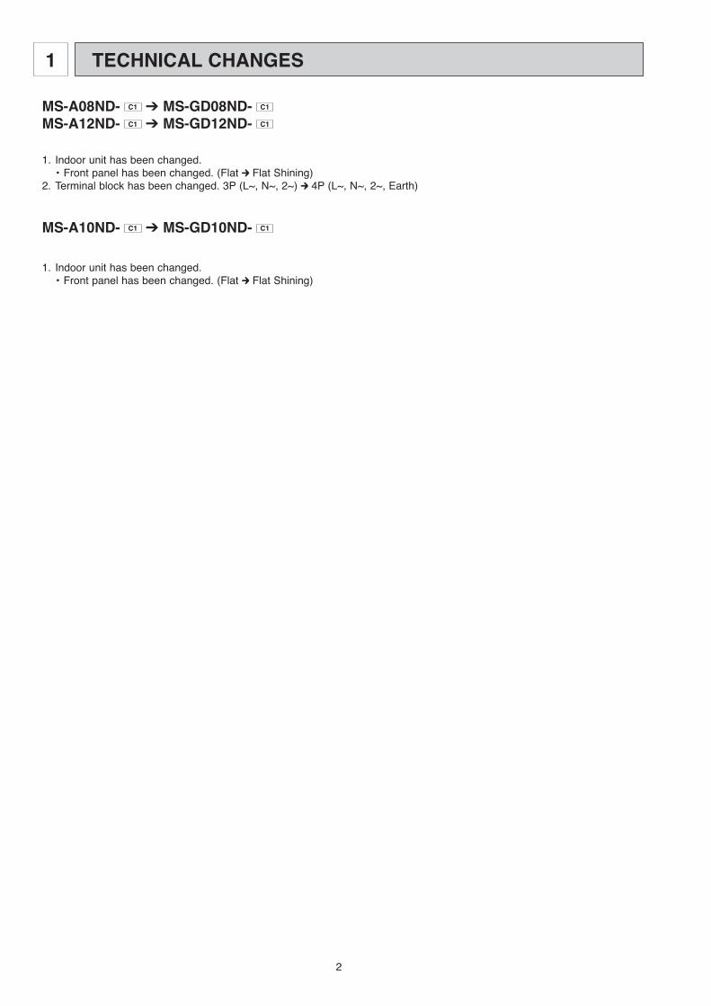
1 TECHNICAL CHANGES
MS-A08ND- C1 ➔ MS-GD08ND- C1
MS-A12ND- C1 ➔ MS-GD12ND- C1
1. Indoor unit has been changed. • Front panel has been changed. (Flat Flat Shining)2. Terminal block has been changed. 3P (L~, N~, 2~) 4P (L~, N~, 2~, Earth)
MS-A10ND- C1 ➔ MS-GD10ND- C1
1. Indoor unit has been changed. • Front panel has been changed. (Flat Flat Shining)
3
2
ACCESSORIES
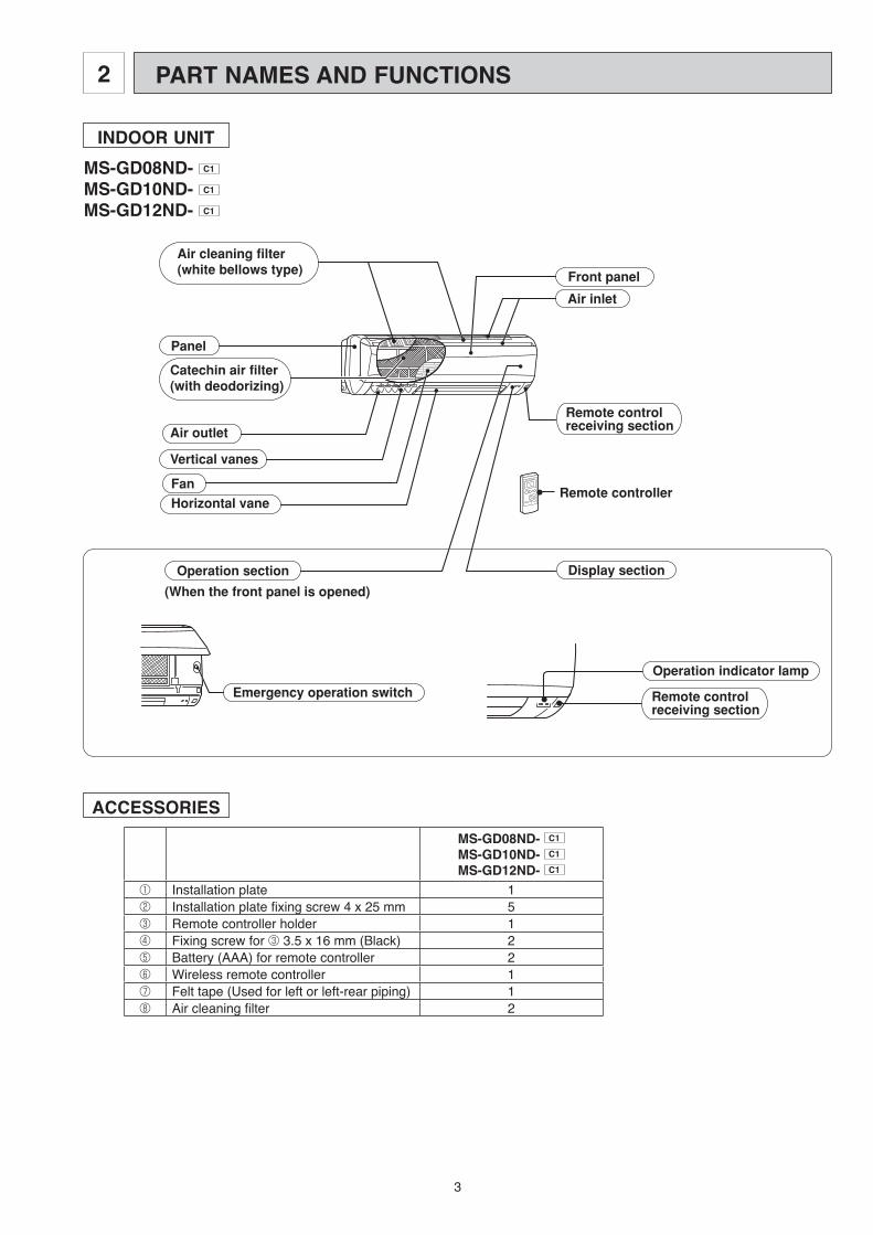
PART NAMES AND FUNCTIONS
INDOOR UNITMS-GD08ND- C1
MS-GD10ND- C1
MS-GD12ND- C1
Emergency operation switch
Fan
Air outlet
Vertical vanes
Air inlet
Remote controlreceiving section
Display section
Air cleaning filter(white bellows type)
Catechin air filter(with deodorizing)
Front panel
Panel
Horizontal vane
Operation section
(When the front panel is opened)
Remote controller
Operation indicator lamp
Remote controlreceiving section
MS-GD08ND- C1
MS-GD10ND- C1
MS-GD12ND- C1
1 Installation plate 1 2 Installation plate fixing screw 4 x 25 mm 5 3 Remote controller holder 1 4 Fixing screw for 3 3.5 x 16 mm (Black) 2 5 Battery (AAA) for remote controller 2 6 Wireless remote controller 1 7 Felt tape (Used for left or left-rear piping) 1 8 Air cleaning filter 2

4
SPECIFICATION3
REMOTE CONTROLLER
ON/OFF
RESET
TOOWARM
TOOCOOL
ECONO COOL
POWERFUL COOL
SELECT
FAN
VANE
TIMEMODE
I FEEL COOL
DRYFAN
h
Signal transmitting section
Operation display section
TEMPERATURE buttons
VANE CONTROL button
TIME SET button
RESET button
ECONO COOL button
POWERFUL COOL button
OPERATION SELECT button
TIMER MODE SELECT button
OPERATE/STOP (ON/OFF) button
FAN SPEED CONTROL button
Indication of remote controller model is on back.
These buttons are able to store the light from nature, fluorescent lamp, etc and shine in the dark.
Indoor model MS-GD08ND- C1 MS-GD10ND- C1 MS-GD12ND- C1
Function Cooling Power supply Single phase 220-230V, 60Hz
Capacity Air flow (High/Med/Low) K/h 588/456/372 630/498/336 666/498/336
Elec
trica
l dat
a Power outlet A 10 Running current A 0.19 Power input W 40 Auxiliary heater A (kW) — Power factor % 96-92 Fan motor current A 0.19
Fan
mot
or Model RC4N19-BA
Winding resistance (at 20ºC) " WHT-BLK 312
BLK-RED 255 Dimensions WoHoD mm 815o278o244 Weight kg 9 10
Spec
ial
rem
arks
Air direction 5 Sound level (High/Med/Low) dB 39/32/26 39/32/26 42/36/29 Fan speed (High/Med/Low) rpm 1030/800/650 960/800/650 1000/800/650 Fan speed regulator 3 Thermistor RT11 (at 25ºC) kΩ 10 Thermistor RT12 (at 25ºC) kΩ 10
Remote controller model MP2B
NOTE: Test conditions are based on CNS 14464 Cooling : Indoor Dry-bulb temperature 27°C Wet-bulb temperature 19°C Outdoor Dry-bulb temperature 35°C Wet-bulb temperature 24°C Refrigerant piping length (one way) 7.5 m
MS-GD08ND- C1
MS-GD10ND- C1
MS-GD12ND- C1
5
[9.52-0.43m
244
242 5
erom ro 7
90
110
03
149606
872
60
815
783
Air out
Installation plate
Insulation [28
Drain hose [16(Connected part O.D)
Liquid line [6.35-0.5mGas line [9.52-0.43mInsulation [37 O.D
[21 I.D{
Wireless remote controller
81.581.5
14 5.2
24
172
5.132
5. 4
81.5 133.5
326326
Wall hole [65
Indoor unit
Installation plate
57
041
17.5
Air in
244
242
5.812
852
81.581.5
14 245.2
5.71
161.5161.5
326326
5
erom ro 7
90
110
03
149606
872
60
815
783
Air out
Indoor unit
Installation plate
Wall hole [65
Installation plate
Insulation [28
Drain hose [16(Connected part O.D)
Air in
Liquid line [6.35-0.5mGas line
Insulation [37 O.D[21 I.D
{
Wireless remote controller
57
041
17.5
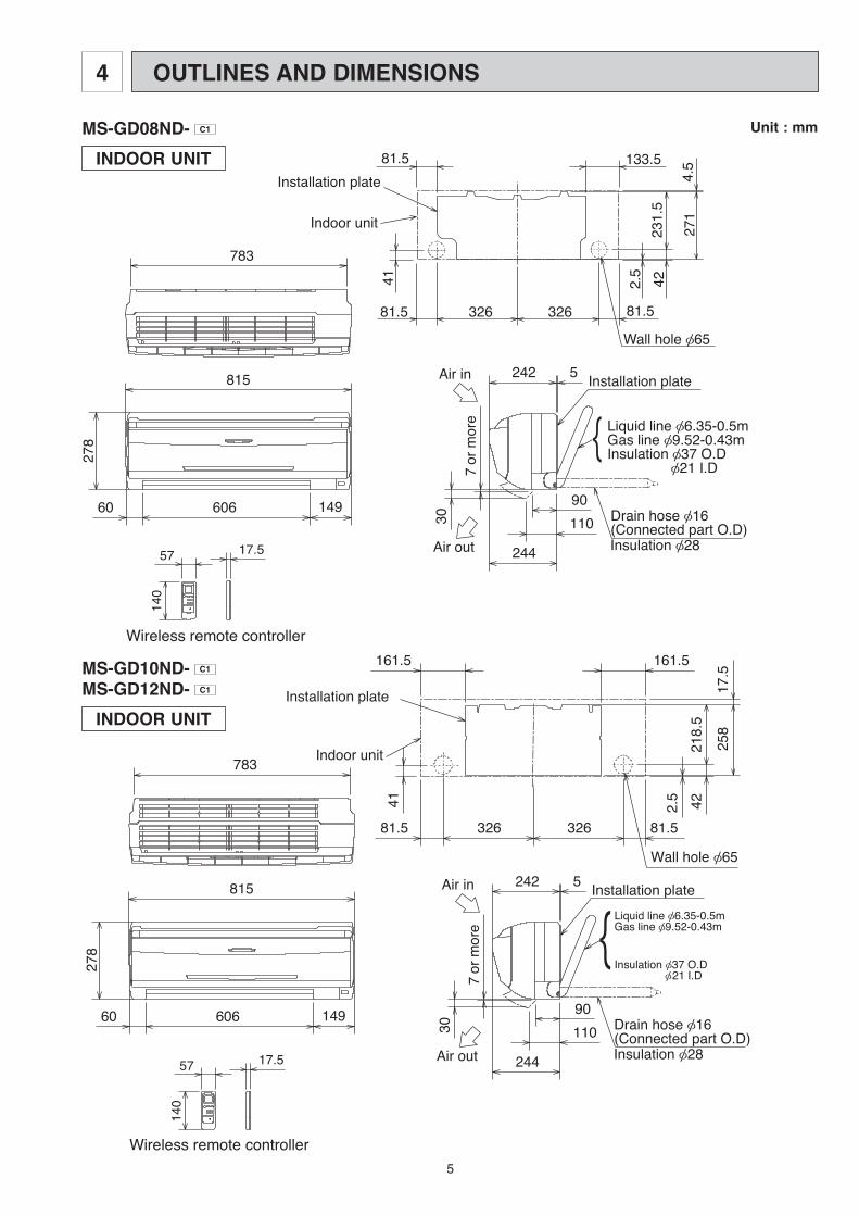
Unit : mm
INDOOR UNIT
OUTLINES AND DIMENSIONS4
MS-GD08ND- C1
INDOOR UNIT
MS-GD10ND- C1
MS-GD12ND- C1

6
MS-GD08ND- C1
MS-GD12ND- C1
WIRING DIAGRAM5
INDOOR UNIT
MS-GD10ND- C1

7
REFRIGERANT SYSTEM DIAGRAM6
MS-GD08ND- C1
MS-GD10ND- C1
INDOOR UNIT
Roomtemperaturethermistor
Indoorheatexchanger
RT11
Indoor coilthermistorRT12
Refrigerant pipe(Option){6.35(with heat insulator)
Flaredconnection
Flaredconnection
Refrigerant pipe(Option){12.7(with heat insulator)
Refrigerant flow in cooling
Roomtemperaturethermistor
Indoorheatexchanger
RT11
Indoor coilthermistorRT12
Refrigerant pipe(Option){6.35(with heat insulator)
Flaredconnection
Flaredconnection
Refrigerant pipe(Option){9.52(with heat insulator)
MS-GD12ND- C1
INDOOR UNIT

8
Table 1
How to set the remote controller exclusively for particular indoor unit After you turn the breaker ON, the first remote controller that sends the signal to the indoor unit will be regarded as the
remote controller for the indoor unit. The indoor unit will only accepts the signal from the remote controller that has been assigned to the indoor unit once they
are set. The setting will be cancelled if the breaker has turned off, or the power supply has shut down. Please conduct the above setting once again after the power has restored.
7-2. P.C. BOARD MODIFICATION FOR INDIVIDUAL OPERATION A maximum of 4 indoor units with wireless remote controllers can be used in a room. In this case, to operate each indoor unit individually by each remote controller, P.C. boards of remote controller must be
modified according to the number of the indoor unit.
7-1. TIMER SHORT MODE For service, set time can be shortened by short circuit of JPG and JPS the electronic control P.C. board. The time will be shortened as follows. (Refer to 8-6.) Set time : 1-minute 1-second Set time : 3-minute 3-second It takes 3 minutes for the compressor to start operation. However, the starting time is shortened by short
circuit of JPG and JPS.
How to modify the remote controller P.C. boardRemove batteries before modification.The board has a print as shown below :
NOTE : For remodelling, take out the bat-teries and push the OPERATE/STOP(ON/OFF)button twice or 3 times at first.
After finish remodelling, put back the batteries then press the RESET button.
Remote controller model : MP2B
The P.C. board has the print “J1” and “J2”. Solder “J1” and “J2” according to the number of indoor unit as shown in Table 1.After modification, press the RESET button.
J2J1
SERVICE FUNCTIONS7
MS-GD08ND- C1
MS-GD10ND- C1
MS-GD12ND- C1
1 unit operation 2 units operation 3 units operation 4 units operationNo. 1 unit No modification Same as at left Same as at left Same as at leftNo. 2 unit — Solder J1 Same as at left Same as at leftNo. 3 unit — — Solder J2 Same as at leftNo. 4 unit — — — Solder both J1 and J2

9
When the indoor unit is controlled with the remote controller, the operation mode, set temperature, and the fan speed are memorized by the indoor electronic control P.C.board. The “AUTO RESTART FUNCTION” sets to work the moment power has restored after power failure. Then, the unit will restart automatically. However if the unit is operated in “I FEEL CONTROL” mode before power failure, the operation is not memorized. In “I FEEL CONTROL” mode, the operation is decided by the initial room temperature.
How to release “AUTO RESTART FUNCTION” 1 Turn off the main power for the unit. 2 Pull out the indoor electronic control P.C. board and the power monitor, receiver
P.C. board. (Refer to 9-1.) 3 Solder the Jumper wire to the JR07 on the indoor electronic control P.C.board.
(Refer to 8-6.)
7-3. AUTO RESTART FUNCTION
NOTE: • The operation settings are memorized when 10 seconds have passed after the indoor unit was operated with the remote
controller. • If the main power is turned off or a power failure occurs while AUTO START/STOP timer is active, the timer setting is cancelled. • If the unit has been off with the remote controller before power failure, the auto restart function does not work as the
power button of the remote controller is off. • To prevent breaker off due to the rush of starting current, systematize other home appliances not to turn on at the same
time.• When some air conditioners are connected to the same supply system, if they are operated before power failure, the starting current of all the compressors may flow simultaneously at restart. Therefore, the special counter-measures are required to prevent the main voltage-drop or the rush of the starting current by adding to the system that allows the units to start one by one.
Operation 1 If the main power has been cut, the operation settings remain. 2 After the power is restored, the unit automatically resumes the same operation as the memory has recorded. However, it takes the compressor at least 3 minutes to get started.
JR07
IC101
CN151
SW1
CN112
CN111
CN201
52C/X10
C11CN211
CN1V1
CN1R1CN121
10
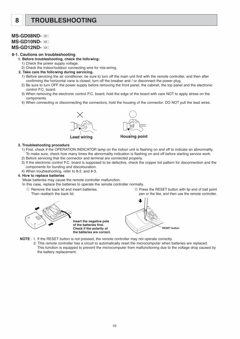
8-1. Cautions on troubleshooting1. Before troubleshooting, check the following:
1) Check the power supply voltage.2) Check the indoor/outdoor connecting wire for mis-wiring.
2. Take care the following during servicing.1) Before servicing the air conditioner, be sure to turn off the main unit first with the remote controller, and then after
confirming the horizontal vane is closed, turn off the breaker and / or disconnect the power plug.2) Be sure to turn OFF the power supply before removing the front panel, the cabinet, the top panel and the electronic
control P.C. board.3) When removing the electronic control P.C. board, hold the edge of the board with care NOT to apply stress on the
components.4) When connecting or disconnecting the connectors, hold the housing of the connector. DO NOT pull the lead wires.
Lead wiring Housing point
3. Troubleshooting procedure1) First, check if the OPERATION INDICATOR lamp on the indoor unit is flashing on and off to indicate an abnormality.
To make sure, check how many times the abnormality indication is flashing on and off before starting service work.2) Before servicing that the connector and terminal are connected properly.3) If the electronic control P.C. board is supposed to be defective, check the copper foil pattern for disconnection and the
components for bursting and discolouration.4) When troubleshooting, refer to 8-2. and 8-3.
4. How to replace batteriesWeak batteries may cause the remote controller malfunction.In this case, replace the batteries to operate the remote controller normally.
2 Press the RESET button with tip end of ball point pen or the like, and then use the remote controller.
NOTE : 1. If the RESET button is not pressed, the remote controller may not operate correctly. 2. This remote controller has a circuit to automatically reset the microcomputer when batteries are replaced. This function is equipped to prevent the microcomputer from malfunctioning due to the voltage drop caused by
the battery replacement.
1 Remove the back lid and insert batteries. Then reattach the back lid.
Insert the negative pole of the batteries first.Check if the polarity of the batteries are correct.
RESET button
TROUBLESHOOTING8
MS-GD08ND- C1
MS-GD10ND- C1
MS-GD12ND- C1
11
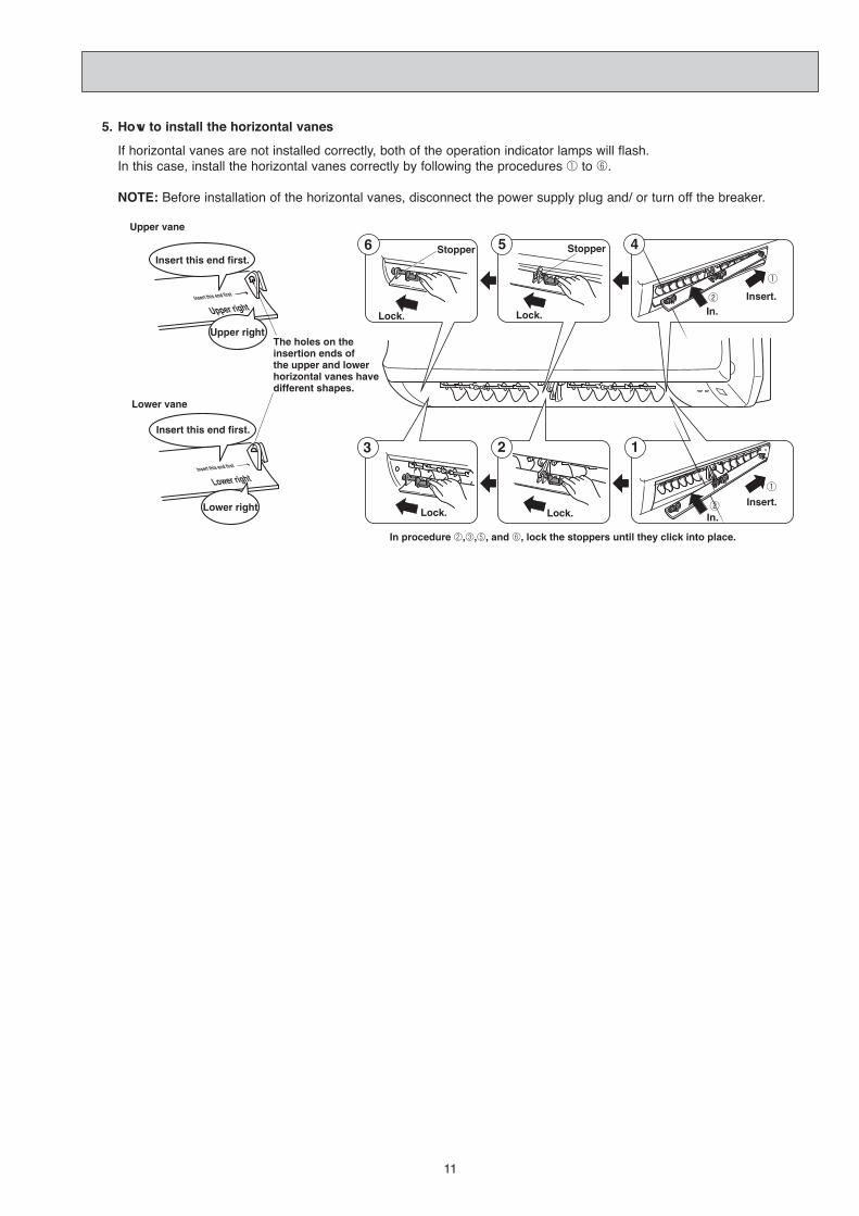
5. How to install the horizontal vanes
Upper vane
Lower vane
The holes on the insertion ends of the upper and lower horizontal vanes havedifferent shapes.
Insert this end first.
Upper right
Lower right
Insert this end first.
6 5 4
3 2 1
In procedure 2,3,5, and 6, lock the stoppers until they click into place.
Stopper
Lock.
Stopper
Lock.
Lock. Lock. In.
Insert.
Insert.In.
If horizontal vanes are not installed correctly, both of the operation indicator lamps will flash.In this case, install the horizontal vanes correctly by following the procedures 1 to 6.
NOTE: Before installation of the horizontal vanes, disconnect the power supply plug and/ or turn off the breaker.
5. How to install the horizontal vanes
If horizontal vanes are not installed correctly, both of the operation indicator lamps will flash. In this case, install the horizontal vanes correctly by following the procedures 1 to 6.
NOTE: Before installation of the horizontal vanes, disconnect the power supply plug and/ or turn off the breaker.
12
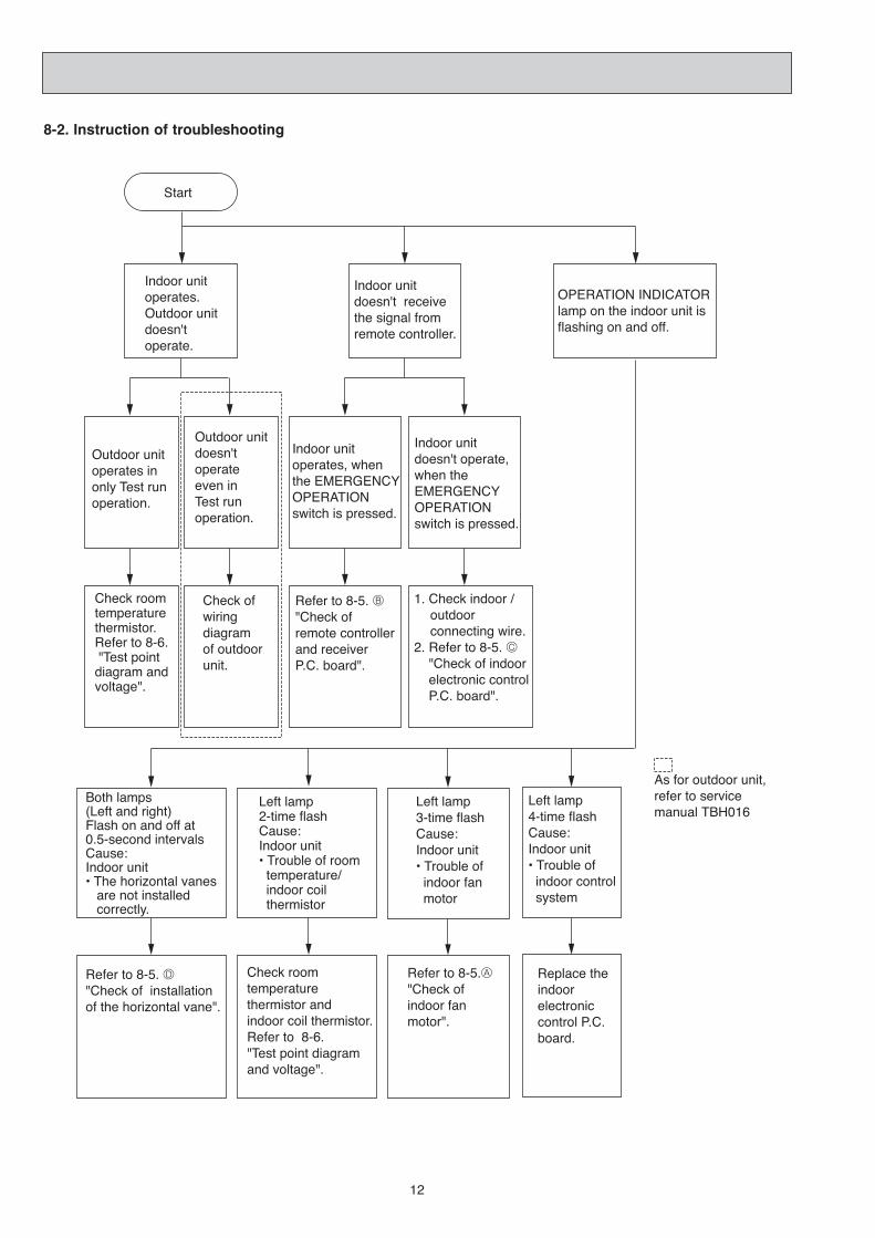
8-2. Instruction of troubleshooting
Start
Indoor unit operates.Outdoor unit doesn'toperate.
Indoor unit doesn't receive the signal from remote controller.
OPERATION INDICATORlamp on the indoor unit is flashing on and off.
Outdoor unit operates in only Test run operation.
Outdoor unit doesn'toperateeven in Test run operation.
Indoor unit operates, when the EMERGENCY OPERATION switch is pressed.
Indoor unit doesn't operate, when the EMERGENCY OPERATION switch is pressed.
Check room temperaturethermistor.Refer to 8-6. "Test point diagram and voltage".
Refer to 8-5. B"Check of remote controller and receiver P.C. board".
Left lamp2-time flash Cause:Indoor unit• Trouble of room temperature/ indoor coil thermistor
Left lamp3-time flash Cause:Indoor unit• Trouble of indoor fan motor
Check room temperaturethermistor and indoor coil thermistor.Refer to 8-6."Test point diagram and voltage".
Refer to 8-5.A"Check of indoor fan motor".
1. Check indoor / outdoor connecting wire.2. Refer to 8-5. C "Check of indoor electronic control P.C. board".
Check of wiringdiagramof outdoor unit.
Left lamp4-time flash Cause:Indoor unit• Trouble of indoor control system
Replace the indoorelectroniccontrol P.C. board.
As for outdoor unit, refer to service manual TBH016
Both lamps(Left and right)Flash on and off at 0.5-second intervalsCause:Indoor unit• The horizontal vanes are not installed correctly.
Refer to 8-5. D"Check of installation of the horizontal vane".

13
Before taking measures, make sure that the symptom reappears for accurate troubleshooting.Self check table
8-3. Troubleshooting check table
• The following indication applies regardless of shape of the indicator.
flashing
Operation Indicator · Flashing of the OPERATION INDICATOR lamp (on the left) indicates possible abnormalities.· The OPERATION INDICATOR lamp (on the left) is lighting during normal operation.
No.
2
SymptomIndication Detection method Check point
Indoor coil thermistor
3Indoor fan motor.
Abnormalpoint
Roomtempera-turethermistor
2-time flash
2.5-second OFF
Detect Indoor coil/room temperature thermistor short or open circuit every 8 seconds during operation.
• Refer to the characteristics ofindoor coil thermistor androom temperature thermistorshown in 8-6.
3-time flash
2.5-second OFF
Indoor fan motor repeats 12 seconds ON and 3 minutes OFF.When the indoor fan motor breaks, the fan keeps stopping.
When rotational frequency feedback signal is not emitting during 12-second indoor fan operation.
• Refer to 8-5.A "Check of indoor fan motor".
Outdoor unit does not operate.
Left lamp flashes.
Left lamp flashes.
Indoorcontrolsystem
4-time flash
2.5-second OFF
Left lamp flashes.
4
• Replace the indoor electronic control P.C. board.
Outdoor unit does not operate.
When it cannot properly read data in the nonvolatile memory of the indoor electronic control P.C. board.
10.5-second ON
0.5-second OFF
When the electricity is not conducted to the safety device (FAN) of the horizontal vane.
• Refer to 8-5. D "Check of installation of the horizontal vane".
Indoor unit and outdoor unit do not operate.
Attachmentof the horizontalvane
Both lamps flash at the same time.
NOTE : When the indoor unit has started operation and the above detection method has detected an abnormality (the first detection after the power ON), the indoor electronic control P.C. board turns OFF the indoor fan motor with the OPERATION INDICATOR lamp flashing.

14
8-4. Trouble criterion of main parts
MS-GD08ND- C1
MS-GD10ND- C1
MS-GD12ND- C1
Vane motor(MV)
Measure the resistance between the terminals with a tester.(Part temperature10°C ~ 30°C)
RED
YLWBRN
ORN GRN
ROTORNormal Abnormal
Open or short-circuit240 ~ 260"
Roomtemperaturethermistor (RT11)
Part name
Indoor coilthermistor(RT12)
Check method and criterion
Measure the resistance with a tester.(Part temperature 10°C ~ 30°C)
Figure
Normal
8k" ~ 20k"
Abnormal
Open or short-circuit
Measure the resistance between the terminals with a tester.(Coil wiring temperature10°C ~ 30°C)
Indoor fanmotor (MF)
INNER FUSE145i 2: CUT OFF
trap rotoM
trap ros neS
Measure the voltage Power ON.
MAIN
AUX.
BLK RED WHT
FUSE
Normal
299~324"WHT-BLK
BLK-RED
Color of lead wire
BRN-YLW
YLW-GRY
Normal
4.5 ~ 5.5V
Abnormal
Remain 0V or 5V(When fan revolved one time)0V→ →5V 0V
(Approx.)
244~265"
Abnormal
Open orshort-circuit
Color of lead wire

15
Yes
B Check of remote controller and receiver P.C. boardw Check if the remote controller is exclusive for this air conditioner.
Replace the batteries.(Refer to 8-1.4.)
Turn on a radio to AM and press switch on the remote controller.
Is noise heard from radio?
Are there any fluorescent lights of inverter or rapid-start type within the range of 1m?
Measure the voltage between receiver P.C. board connector CN302 No.3(-) and No.5(+) when the remote controller button is pressed.
Is the voltage approx. 4V DC? Replace the indoor electronic control P.C. board
Replace the power monitor, receiver P.C.board.
Replace the remote controller.
● Reinstall the unit away from lights.● Attach a filter on receiving part.
Switch on the remote controller.
Is LCD display on the remote con-troller visible?
Remove batteries, then set them back and press the RESET button. Check if the unit operates with remote controller.
Yes
Does the unit operate with remote controller?
Yes
OK
No
(not clear)
Yes
No
No
No(5V or 0V DC)
No
A Check of indoor fan motor Turn OFF the power supply.Check connector CN211 visually.
Disconnect lead wires from connector CN211 on the indoor electronic control P.C. board.Measure resistance between lead wires: No.1 and No.5 and then No.3 and No.5.
Are lead wires connected? Is soldering point of the connector correctly soldered?
Resolder it.Yes
NoNo Yes
Reconnect the lead wires.
Is resistance 0 (short circuit) or ∞ (open circuit)?
Yes ( 0 or ∞)No
(others)
Repair the indoor fan motor.
Insert screwdriver into air outlet to rotate indoor fan motor slowly for 1 revolution or over, and measure voltage No.2(+) and No.3(-) on CN121.
Replace the indoor electronic control P.C. board.
Does voltage repeat 0V DC and 5V DC?
Yes
No
When left OPERATION INDICATOR lamp flashes 3-time. Indoor fan motor doesn’t operate.
Indoor unit operates by pressing the EMERGENCY OPERATION switch, but doesn’t operate with the remote controller.
Yes
8-5. Troubleshooting flow

16
C Check of indoor electronic control P.C. board
The unit doesn’t operate with the remote controller.Also, the OPERATION INDICATOR lamp doesn’t light up by pressing the EMERGENCY OPERATION switch.
CN201LN
13
Terminalblock
Check both “parts side” and “patternside” of the indoor electronic control P.C. board visually.
Replace the fuse.
Is fuse(F11) blown?
Be sure to check both fuse and varistor in any case.
Replace the fan motor.
Replace the indoor electronic control P.C. board.
Is the winding resistance of fan motor 0 "?
Is the winding resistance of vane motor 0 "?
No
Yes
Replace the vane motor.
No
Yes
Yes
Is varistor(NR11) burnt?
Replace the varistor.
Yes
Turn OFF the power supply.Remove indoor fan motor connector CN211 and vane motor connector CN151 from the indoor electronic control P.C. board and turn ON the power supply.
No
No
Does the unit operate with the remote controller?Does the OPERATION INDICATOR lamp light up by pressing the EMERGENCY OPERATION switch?
Yes
No
1.Pull out the power supply cord.2.Measure the resistance between CN201 1 on the indoor electronic control P.C. board and on the terminal block with a tester.
Is there resistance approx. 0 "?
Replace the fuse (F12).
CN201 12
LN
F12
13
Terminalblock
Be sure to check both resistance.
Turn OFF the power supply.
Turn OFF the power supply.
Yes
No(∞)
MS-GD10ND MS-GD08/GD12ND

17
D Check of installation of the horizontal vane
Start
Replace the indoor electronic control P.C. board.
Replace the safety device.
Is the stopper of the horizontal vane locked to the indoor unit correctly?
Yes
No
Is there resistance 0 "?
Relock the stopper of the horizontal vane to the indoor unit. Refer to 8-1-5.
Yes
Is the OPERATION INDICATOR lamp flashing?
Yes
No(∞)
NoOK
Turn ON the power supply.
To check the continuity of safety device, measure the resistance of connector 1 - 3 connected to CN1R1 on the indoor electronic control P.C. board.
Turn OFF the power supply.
Turn OFF the power supply.
When both OPERATION INDICATOR lamps flash ON and OFF every 0.5-second.Indoor unit and outdoor unit don’t operate.

18
Indoor coil thermistor (RT12)Room temperature thermistor (RT11)
Temperature (:)
Res
ista
nce
(k"
)
Release of Auto restart functionSolder the Jumper wire to the JR07. (Refer to 7-3.)
CN302
Power monitor, receiver P.C. board
Power supply input220 - 230V AC
Varistor (NR11)
Fuse 250V AC 3.15A
Room temperaturethermistor (RT11)Indoor coilthermistor (RT12)
Timer short mode point JPG, JPS(Refer to 7-1.)
Emergencyoperation switch
}
} Indoor fan motor 220 - 230V AC
}
5V DC
+–
{12V DC
+– }}
J23J33
J33
J12
8-6. Test point diagram and voltage
Safety device of fan by horizontal vane CN1R1
Varistor (NR12)
Indoor electronic control P.C. board
MS-GD08ND- C1
MS-GD10ND- C1
MS-GD12ND- C1
19
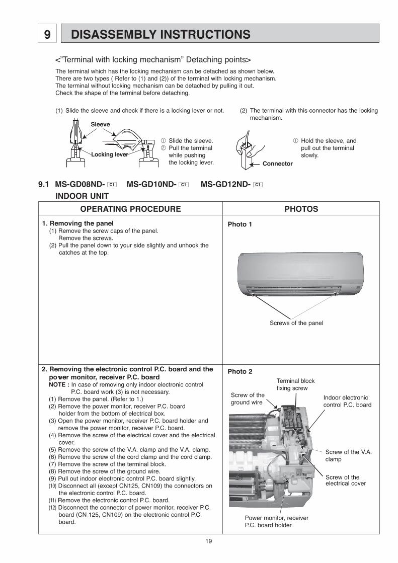
9.1 MS-GD08ND- C1 MS-GD10ND- C1 MS-GD12ND- C1
OPERATING PROCEDURE PHOTOS
Photo 1
Screws of the panel
1. Removing the panel(1) Remove the screw caps of the panel. Remove the screws.(2) Pull the panel down to your side slightly and unhook the
catches at the top.
2. Removing the electronic control P.C. board and the power monitor, receiver P.C. boardNOTE : In case of removing only indoor electronic control
P.C. board work (3) is not necessary.(1) Remove the panel. (Refer to 1.)(2) Remove the power monitor, receiver P.C. board holder from the bottom of electrical box.(3) Open the power monitor, receiver P.C. board holder and
remove the power monitor, receiver P.C. board.(4) Remove the screw of the electrical cover and the electrical
cover.(5) Remove the screw of the V.A. clamp and the V.A. clamp.(6) Remove the screw of the cord clamp and the cord clamp.(7) Remove the screw of the terminal block.(8) Remove the screw of the ground wire.(9) Pull out indoor electronic control P.C. board slightly.(10) Disconnect all (except CN125, CN109) the connectors on
the electronic control P.C. board.(11) Remove the electronic control P.C. board.(12) Disconnect the connector of power monitor, receiver P.C.
board (CN 125, CN109) on the electronic control P.C. board.
Terminal blockfixing screw
Screw of the V.A.clamp
Indoor electronic control P.C. board
Screw of theground wire
Power monitor, receiver P.C. board holder
Screw of theelectrical cover
Photo 2
DISASSEMBLY INSTRUCTIONS9
<”Terminal with locking mechanism” Detaching points>The terminal which has the locking mechanism can be detached as shown below.There are two types ( Refer to (1) and (2)) of the terminal with locking mechanism.The terminal without locking mechanism can be detached by pulling it out.Check the shape of the terminal before detaching.
(1) Slide the sleeve and check if there is a locking lever or not. (2) The terminal with this connector has the locking mechanism.
Sleeve
Locking lever
1 Slide the sleeve.2 Pull the terminal while pushing the locking lever.
1 Hold the sleeve, and pull out the terminal slowly.
Connector
INDOOR UNIT

20
OPERATING PROCEDURE PHOTOS
Photo 5
Photo 7
Screws of the left side of the heat exchanger
Photo 6
Hooks of themotor band
Hexagon socket set screw
Screw of the lead cover
5. Removing the indoor fan motor and the line flow fan (1) Remove the panel. (Refer to 1.)(2) Remove the electrical box. (Refer to 3.)(3) Pull out the drain hose from the nozzle assembly, and
remove the nozzle assembly. (Refer to 4.)(4) Remove the screw of the lead cover and lead cover.(5) Release the hooks to open the motor band slightly.(6) Loosen the hexagon socket set screw from the line flow
fan.(7) Remove the screws fixing the motor bed, and remove the
fan motor with motor band and the motor bed.(8) Remove the screws fixing the left side of the heat exchanger.(9) Lift the left side of the heat exchanger.(10) Remove the line flow fan.
Screws of the motorbed
3. Removing the electrical box(1) Remove the panel. (Refer to 1.)(2) Remove the electrical cover. (Refer to 2.)(3) Remove the V.A. clamp. (Refer to 2.)(4) Remove the cord clamp. (Refer to 2.)(5) Remove the terminal block. (Refer to 2.)(6) Remove the screw of ground wire. (Refer to 2.)(7) Disconnect the connector of the indoor coil thermistor
(CN112), the fan motor connector (CN211 and CN121) and the vane motor connector (CN151)on the electronic control P.C. board.
(8) Remove the fan motor lead wire and indoor coil thermistor from the electrical box.
(9) Remove the lead wire of vane motor from the bottom of electrical box.
(10) Remove the screw fixing the electrical box, remove the electrical box.
Photo 3 Indoor coil thermistorconnector
Fan motor connectors
Vane motor connector
Screw of the electrical box
Photo 4
Drain hose
Screws of the vane motor4. Removing the nozzle assembly and the vane motor
(1) Remove the panel. (Refer to 1.)(2) Remove the electrical box. (Refer to 3.)(3) Pull out the drain hose from the nozzle assembly, remove
the nozzle assembly.(4) Remove the screws of the vane motor, disconnect the vane motor connector.(5) Remove the vane motor.

HEAD OFFICE: TOKYO BLDG., 2-7-3, MARUNOUCHI, CHIYODA-KU, TOKYO 100-8310, JAPAN
MITSUBISHI ELECTRIC CONSUMER PRODUCTS (THAILAND) CO., LTD.AMATA NAKORN INDUSTRIAL ESTATE 700/406 MOO 7, TAMBON DON HUA ROH, AMPHUR MUANG, CHONBURI 20000 THAILAND Made in Thailand
New publication, effective Feb. 2008Specifications subject to change without notice.
TM