Embed Size (px)
Citation preview

SERVICE ORIENTED SYSTEM DESIGN THROUGH PROCESS DECOMPOSITION
A THESIS SUBMITTED TO THE GRADUATE SCHOOL OF NATURAL AND APPLIED SCIENCES
OF MIDDLE EAST TECHNICAL UNIVERSITY
BY
EREN KOÇAK AKBIYIK
IN PARTIAL FULFILLMENT OF THE REQUIREMENTS FOR
THE DEGREE OF MASTER OF SCIENCE IN
COMPUTER ENGINEERING
AUGUST 2008

Approval of the thesis:
SERVICE ORIENTED SYSTEM DESIGN THROUGH PROCESS DECOMPOSITION
submitted by EREN KOÇAK AKBIYIK in partial fulfillment of the requirements for the degree of Master of Science in Computer Engineering Department, Middle East Technical University by, Prof. Dr. Canan Özgen _____________________ Dean, Graduate School of Natural and Applied Sciences Prof. Dr. Volkan Atalay _____________________ Head of Department, Computer Engineering Assoc. Prof. Dr. Ali Hikmet Doğru _____________________ Supervisor, Computer Engineering Dept., METU Examining Committee Members: Assoc. Prof. Dr. Tolga Can _____________________ Computer Engineering Dept., METU Assoc. Prof. Dr. Ali Hikmet Doğru _____________________ Computer Engineering Dept., METU Dr. Cevat Şener _____________________ Computer Engineering Dept., METU Asst. Prof. Dr. Osman Abul _____________________ Computer Engineering Dept., TOBB ETU Senior Lead Software Design Eng. Bülent Durak _____________________ Software Engineering Dept., Aselsan Inc. Date: _____________________

iii
I hereby declare that all information in this document has been obtained and presented in accordance with academic rules and ethical conduct. I also declare that, as required by these rules and conduct, I have fully cited and referenced all material and results that are not original to this work. Name, Last name : Eren Koçak AKBIYIK Signature :

iv
ABSTRACT
SERVICE ORIENTED SYSTEM DESIGN THROUGH PROCESS DECOMPOSITION
AKBIYIK, Eren Koçak
M.Sc., Department of Computer Engineering
Supervisor: Assoc. Prof. Dr. Ali Hikmet DOĞRU
August 2008, 99 pages
Although service oriented architecture has reached a particular maturity level
especially in the technological dimension, there is a lack of common and acceptable
approach to design a software system through composition and integration of web
services. In this thesis, a service oriented system design approach for Service
Oriented Architecture based software development is introduced to fill this gap. This
new methodology basically offers a procedural top-down decomposition of a given
software system allowing several abstraction levels. At the higher levels of the
decomposition, the system is divided into abstract nodes that correspond to process
models in the decomposition tree. Any node is a process and keeps the sequence and
the state information for the possible sub-processes in this decomposition tree. Nodes
which are defined as process models may include some sub-nodes to present details
for the intermediate levels of the model. Eventually at the leaf level, process models
are decomposed into existing web services as the atomic units of system execution.
All processes constructing the system decomposition tree are modeled with BPEL
(Business Process Execution Language) to expose the algorithmic details of the
design. This modeling technique is also supported with a graphical modeling

v
language referred to as SOSEML (Service Oriented Software Engineering Modeling
Language) that is also newly introduced in this thesis.
Keywords: Service Oriented Architecture, Service Oriented System Design,
Procedural Decomposition, Process Models, Business Process Execution Language,
Service Oriented Software Engineering Modeling Language

vi
ÖZ
SÜREÇ AYRIŞTIRMA İLE SERVİS YÖNELİMLİ SİSTEM TASARIMI
AKBIYIK, Eren Koçak
Yüksek Lisans, Bilgisayar Mühendisliği Bölümü
Tez Danışmanı: Doç. Dr. Ali Hikmet DOĞRU
Ağustos 2008, 99 sayfa
Her ne kadar servis yönelimli mimari özellikle teknolojik boyutta dikkate değer bir
olgunluk seviyesine ulaşmış olsa da, bir yazılım sistemini ağ servislerinin bileşimi ve
bütünleşmesi üzerinden tasarlamak için ortak ve kabul edilebilir bir yaklaşımın
eksiliği söz konusudur. Bu tezde, bahsedilen eksikliği gidermek üzere, servis
yönelimli mimari tabanlı yazılım geliştirme için bir servis yönelimli sistem tasarım
yaklaşımı tanıtılmaktadır. Bu yeni yöntem, temel olarak, verilen bir yazılım
sisteminin çeşitli soyutlama düzeyleri ile yukarıdan aşağıya süreçsel ayrıştırılmasını
önermektedir. Çözümlemenin üst düzeylerinde, sistem, her biri çözümleme ağacında
bir süreç modeline karşılık gelen soyut düğümlere bölünür. Her düğüm bir süreçtir ve
çözümleme ağacındaki olası alt süreçler için sıra ve durum bilgilerini tutar. Süreç
modelleri olarak tanımlanan düğümler modelin orta düzeyleri için ayrıntılar sunmak
adına bazı alt düğümler içerebilirler. Sonunda, yaprak düzeyinde, süreç modelleri,
sistem çalışmasının atomik birimleri olarak var olan ağ servislerine çözümlenirler.
Sistem ayrıştırma ağacını oluşturan tüm süreçler, tasarımın algoritmik detayını da
ortaya koymak için BPEL (İş Süreci Yürütme Dili) ile modellenirler. Bu modelleme
tekniği, ayrıca, yine bu tezde tanıtılan ve SOSEML (Servis Yönelimli Yazılım

vii
Mühendisliği Modelleme Dili) olarak adlandırılan grafiksel bir modelleme dili ile de
desteklenmektedir.
Anahtar Kelimeler: Servis Yönelimli Mimari, Servis Yönelimli Sistem Tasarımı,
Süreçsel Ayrıştırma, Süreç Modelleri, İş Süreci Yürütme Dili, Servis Yönelimli
Yazılım Mühendisliği Modelleme Dili

viii
ACKNOWLEDGMENTS
First of all, I would like to express my sincere thanks to my supervisor, Assoc. Prof.
Dr. Ali Hikmet DOĞRU for his efforts and guidance throughout this thesis work.
I would like to thank my family for their support and patience.
I would also like to thank my friends Cengiz Toğay, Selma Süloğlu, and all my
friends not named for their support during my M.Sc.
ix
TABLE OF CONTENTS
ABSTRACT ......................................................................................................................iv
ÖZ......................................................................................................................................vi
ACKNOWLEDGMENTS.............................................................................................. viii
TABLE OF CONTENTS..................................................................................................ix
LIST OF TABLES ............................................................................................................xi
LIST OF FIGURES .........................................................................................................xii
LIST OF ABBREVIATIONS .........................................................................................xiv
CHAPTERS
1. INTRODUCTION..........................................................................................................1
1.1 Design and Modeling of Target Systems..............................................................1
1.2 Component and Service Oriented Software Development and Methodologies......2
1.3 Organization of the Thesis...................................................................................7
2. BACKGROUND ............................................................................................................8
2.1 Web Services ......................................................................................................8
2.2 Service Oriented Architecture............................................................................11
2.2.1 SOA Concepts ......................................................................................................... 12
2.2.2 SOA and Web Services ............................................................................................ 14
2.3 Business Process Management ..........................................................................16
2.3.1 Importance of Business Processes ............................................................................ 17
2.3.2 Business Process Execution Language (BPEL)......................................................... 19
2.3.2.1 Features of BPEL ................................................................................................... 19 2.3.2.2 BPEL and Other Languages .................................................................................... 21 2.3.2.3 Developing Business Processes with BPEL ............................................................. 22
3. SYSTEM DESIGN THROUGH PROCESS DECOMPOSITION .............................23
3.1 Basics of SOSEML Philosophy .........................................................................23
3.2 Modeling with SOSEML...................................................................................26
3.2.1 SOSEML Notation................................................................................................... 27
3.2.2 Constructing a Decomposition Tree.......................................................................... 30
x
3.2.3 Modeling Processes in Decomposition Tree.............................................................. 34
3.2.3.1 Process Modeling Basics......................................................................................... 34 3.2.3.2 Using BPEL for Process Modeling.......................................................................... 36
4. SOSE MODELING TOOL..........................................................................................42
4.1 Implementation of SOSECASE .........................................................................42
4.2 Features of SOSECASE ....................................................................................43
4.2.1 Menu Operations ..................................................................................................... 44
4.2.2 Model Panel Operations and SOSEML Tool Bar ...................................................... 46
4.3 BPEL Designer .................................................................................................50
5. A CASE STUDY: MODELING A MILITARY DEPLOYMENT PLANNING SYSTEM ..........................................................................................................................55
5.1 Description of the System Concepts...................................................................55
5.2 Description of the Military Deployment Planning Software ...............................58
5.3 Modeling the System.........................................................................................60
5.3.1 Decomposing the System into Sub Processes............................................................ 61
5.3.2 Considering the Web Services.................................................................................. 64
5.3.3 Creating BPEL Models for the Processes.................................................................. 70
5.3.3.1 Inventory Procurance Process Model....................................................................... 71 5.3.3.2 Weapons Deployment Process Model...................................................................... 74 5.3.3.3 Sensors Deployment Process Model........................................................................ 75 5.3.3.4 Unit Deployment Process Model............................................................................. 77 5.3.3.5 PTL Decisions Process Model................................................................................. 78 5.3.3.6 SRS Decisions Process Model................................................................................. 80 5.3.3.7 Task Orders Decision Process Model ...................................................................... 81 5.3.3.8 Deployment Decision Support Process Model.......................................................... 83 5.3.3.9 Battlefield Geometries Supply Process Model.......................................................... 85 5.3.3.10 Map Layers Presentation Process Model.................................................................. 87 5.3.3.11 Info Layers Presentation Process Model .................................................................. 88 5.3.3.12 Plan Presentation Process Model............................................................................. 89 5.3.3.13 Military Deployment Planning Process Model ......................................................... 90
6. CONCLUSION AND FUTURE WORK.....................................................................93
REFERENCES ................................................................................................................97

xi
LIST OF TABLES
Table 1 – Introduced Specifications by Web Services .............................................10
Table 2 – The Most Important SOA Concepts.........................................................12
Table 3 – BPEL Symbols Used in SOSEML...........................................................29
Table 4 – Web Services Used by the Processes .......................................................69
xii
LIST OF FIGURES
Figure 1 – A General Process Model for Component Oriented Development (Adapted from [3])....................................................................................................4
Figure 2 – Hierarchical Decomposition (Adapted from [5]) ......................................6
Figure 3 – Architectural View of SOA and Positions of Concepts ...........................14
Figure 4 – Choreography, Orchestration and Web Services.....................................16
Figure 5 – Timeline of Business Process Modeling Languages ...............................22
Figure 6 – Modeling Emphasis for Different Approaches (Adapted from [3]) .........25
Figure 7 – Graphical Modeling Elements in SOSEML............................................27
Figure 8 – General Structure of a Decomposition Tree in SOSEML Notation .........32
Figure 9 – Decomposition and Modeling Approaches .............................................35
Figure 10 – Partner Link Definitions for LibrarySearchProcess...............................37
Figure 11 – Variable Definitions Used in LibrarySearchProcess .............................38
Figure 12 – Definition of the Flow of LibrarySearchProcess ...................................39
Figure 13 – Graphical Representation of LibrarySearchProcess Flow......................40
Figure 14 – General View of SOSECASE Main Window .......................................43
Figure 15 – Inner Menu Items of SOSECASE Main Menu......................................44
Figure 16 – Popup Menu for Nodes ........................................................................45
Figure 17 – SOSEML Tool Bar...............................................................................46
Figure 18 – Properties Window for Web Services ...................................................47
Figure 19 – Properties Window for Web Service Interfaces ....................................48
Figure 20 – Representation of Processes in Model Panel.........................................49
Figure 21 – Properties Window for a Process without BPEL Model........................49
Figure 22 – Properties Window for a Process with BPEL Model.............................50
Figure 23 – BPEL Process Templates .....................................................................51
xiii
Figure 24 – General View of BPEL Designer..........................................................52
Figure 25 – Editing WSDL Files in BPEL Designer................................................54
Figure 26 – Primary Target Line and Radiation Segments for Weapons and Sensors...............................................................................................................................57
Figure 27– Inputs and Output of Military Deployment Planning Software ..............58
Figure 28 – A Sample Deployment Plan .................................................................60
Figure 29 – 1st Level Decomposition of the System................................................61
Figure 30 – 2nd and 3rd Level Decompositions for Deployment Decision Process ...62
Figure 31 – 2nd Level Decomposition for Plan Presentation Process........................63
Figure 32 – The Entire Decomposition Tree............................................................64
Figure 33 – Web Services Used by Leaf Level Processes I......................................65
Figure 34 – Web Services Used by Leaf Level Processes II ....................................66
Figure 35 – Web Services Used by Leaf Level Processes III ...................................67
Figure 36 – The Entire Decomposition Tree with Web Services and Interfaces .......68
Figure 37 – BPEL Model for Inventory Procurance Process....................................72
Figure 38 – BPEL Model for Weapons Deployment Process...................................74
Figure 39 – BPEL Model for Sensors Deployment Process .....................................76
Figure 40 – BPEL Model for Unit Deployment Process ..........................................77
Figure 41 – BPEL Model for PTL Decisions Process ..............................................79
Figure 42 – BPEL Model for SRS Decisions Process ..............................................80
Figure 43 – BPEL Model for Task Orders Decision Process ...................................82
Figure 44 – BPEL Model for Deployment Decision Support Process ......................84
Figure 45 – BPEL Model for Battlefield Geometries Supply Process ......................86
Figure 46 – BPEL Model for Map Layers Presentation Process ..............................87
Figure 47 – BPEL Model for Info Layers Presentation Process ...............................88
Figure 48 – BPEL Model for Plan Presentation Process ..........................................90
Figure 49 – BPEL Model for Military Deployment Planning Process......................91

xiv
LIST OF ABBREVIATIONS
ACID Atomicity, Consistency, Isolation, and Durability
BFG Battlefield Geometries
BPEL Business Process Execution Language
BPEL4WS Business Process Execution Language for Web Services
BPM Business Process Management
BPML Business Process Markup Language
BPMN Business Process Modeling Notation
BPSS Business Process Specification Schema
CCM CORBA Component Model
COM Component Object Model
CORBA Common Object Request Broker Architecture
COSE Component Oriented Software Engineering
COSEML Component Oriented Software Engineering Modeling
Language
DCE Distributed Computing Environment
DCOM Distributed Component Object Model
EAI Enterprise Application Integration
EJB Enterprise Java Beans
FTP File Transfer Protocol
GIS Geographical Information Systems
HTTP Hyper Text Transfer Protocol
IT Information Technologies
MIME Multipurpose Internet Mail Extensions
MSMQ Microsoft Message Queue
OASIS Organization for the Advancement of Structured Information
Standards
xv
ORB Object Request Broker
QoS Quality of Service
PTL Primary Target Line
RMI Remote Method Invocation
RPC Remote Procedure Call
SMTP Simple Mail Transfer Protocol
SOA Service Oriented Architecture
SOAP Simple Object Access Protocol
SOSE Service Oriented Software Engineering
SOSECASE Service Oriented Software Engineering Tool
SOSEML Service Oriented Software Engineering Modeling Language
SRS Sensor Radiation Segments
UDDI Universal Description, Discovery and Integration
W3C World Wide Web Consortium
WS Web Service
WSBPEL TC Web Services Business Process Execution Language
Technical Committee
WS-CDL Web Services Choreography Description Language
WSCI Web Services Choreography Interface
WSCL Web Services Conversation Language
WSDL Web Service Description Language
WSFL Web Services Flow Language
XLANG X Language
XML Extended Markup Language
1
CHAPTER 1
1. INTRODUCTION
1.1 Design and Modeling of Target Systems
Design and modeling of target systems have especially been emphasized to comply
with decomposition approaches [1]. Whatever the problem and solution domains are,
models and designs are needed to analyze and solve the complex systems. In general,
complexity is a common property of the systems that are made of different parts and
that the emergent behavior is hard to characterize. When the subject is to design a
complex system, to find a way of decomposing it into independent or at least
approximately independent parts is one of the most powerful techniques. These parts
which can be thought as components correspond to some functional parts of the
target system. Design and solution of each system part can be done with some degree
of independence of the design of others. The idea behind the independency is that
each component affects others through its final function or behavior. The interaction
and communication between the system parts is done through defined interfaces. So
the internal details of the design of each part are not directly related to whole system
design.
In fact it is possible to see lots of examples of modeling techniques based on
decomposition approach in the history of software development methodologies.
Functional programming, object-oriented programming, rule-based systems and
nearly decomposable systems are such examples [1]. In the earlier days of the
computing, the units subject to decomposition were functions or modules. Structural
programming languages such as Pascal and C created hierarchical structures to avoid
unmanageable complexity of coding with “goto” statements. The next evolution was
object-oriented principles and units subject to decomposition changed to abstract
2
classes which bundle the state variables and operations into entities called objects
[2]. Later on, the decompositions units are thought as components, web services and
processes which are at more business abstraction level.
Experiences show that, design and modeling of target systems basically aims to
avoid the complexity of real life problems in a way of procedural or structural
decomposition of the system. The design technique that is introduced in this thesis is
also based on the functional decomposition of the system through process models.
1.2 Component and Service Oriented Software Development and Methodologies
After the introduction of modular design and development notions, reusability has
gained further importance. Software developers noticed that although most of
common sub problems in some specific domains have been resolved, same code
portions have been rewritten by different people every time they were needed. In fact
benefits of reuse (such as in quality, reliability, cost, time and productivity) and other
savings that can be attained by using existing software pieces were obvious [4].
The investigated notion was “building by integration” rather than coding in theory.
But it is certain that the reuse paradigm has experienced a breakthrough with
practical component technologies such as Sun Microsystems’ JavaBeans and
Microsoft DCOM’s ActiveX. Such technologies have been leveraged in the
development of methodologies and engineering approaches [16]. Following a
component oriented philosophy it is assumed that components of a mature domain
are available before a top-down structural decomposition of system will be
conducted. A Component Oriented Software Engineering (COSE) process model has
been proposed by A.H. Dogru and M.M. Tanik in 2003. This philosophy is based on
using available components which are created by exploiting component-based
technologies and already exist in the domain. The fundamental principle of the
process was modeling with integration of components instead of development of new

3
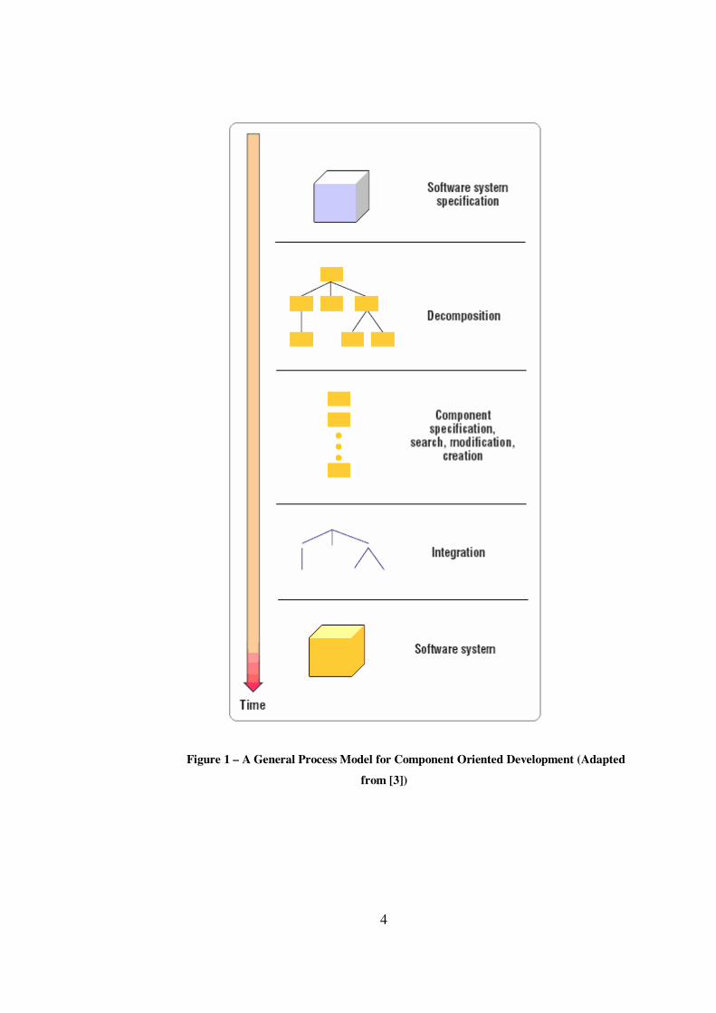
components [3]. The general process model for component oriented development is
depicted in Figure 1.
4
Figure 1 – A General Process Model for Component Oriented Development (Adapted
from [3])
5
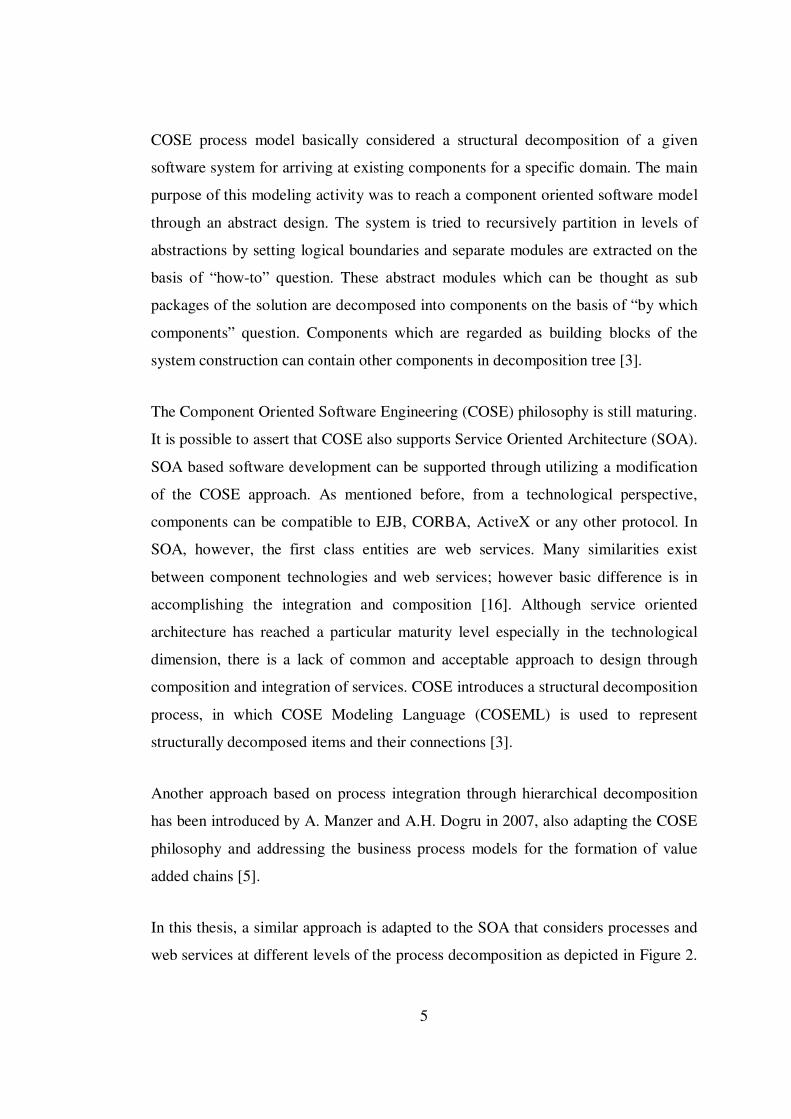
COSE process model basically considered a structural decomposition of a given
software system for arriving at existing components for a specific domain. The main
purpose of this modeling activity was to reach a component oriented software model
through an abstract design. The system is tried to recursively partition in levels of
abstractions by setting logical boundaries and separate modules are extracted on the
basis of “how-to” question. These abstract modules which can be thought as sub
packages of the solution are decomposed into components on the basis of “by which
components” question. Components which are regarded as building blocks of the
system construction can contain other components in decomposition tree [3].
The Component Oriented Software Engineering (COSE) philosophy is still maturing.
It is possible to assert that COSE also supports Service Oriented Architecture (SOA).
SOA based software development can be supported through utilizing a modification
of the COSE approach. As mentioned before, from a technological perspective,
components can be compatible to EJB, CORBA, ActiveX or any other protocol. In
SOA, however, the first class entities are web services. Many similarities exist
between component technologies and web services; however basic difference is in
accomplishing the integration and composition [16]. Although service oriented
architecture has reached a particular maturity level especially in the technological
dimension, there is a lack of common and acceptable approach to design through
composition and integration of services. COSE introduces a structural decomposition
process, in which COSE Modeling Language (COSEML) is used to represent
structurally decomposed items and their connections [3].
Another approach based on process integration through hierarchical decomposition
has been introduced by A. Manzer and A.H. Dogru in 2007, also adapting the COSE
philosophy and addressing the business process models for the formation of value
added chains [5].
In this thesis, a similar approach is adapted to the SOA that considers processes and
web services at different levels of the process decomposition as depicted in Figure 2.

6
The whole system can be modeled as a complex and single process which can be
decomposed into smaller abstract processes. These abstract processes modeled as
more visual logical entities in decomposition tree decomposed into existing web
services at the leaf level. Processes that are closed to leaf level are supposed to be
more real and concrete processes which cover more detailed information about the
sequence and ordering of the system execution. In these processes possible web
service calls are also included to realize a particular business.
Figure 2 – Hierarchical Decomposition (Adapted from [5])
7
The research in this thesis enhances the ideas of A. Manzer and A.H. Dogru towards
SOA based constructs and tries to present a modeling approach for SOA based
software systems as summarized above.
1.3 Organization of the Thesis
This thesis work includes 6 chapters. In Chapter 2, necessary background on service
oriented architecture and web services, business process management and process
models and basics of the COSE philosophy (that is accepted as the motivation and
source of SOSE philosophy) are included. In Chapter 3, proposed system modeling
approach through process decomposition is defined with the description and
representation of SOSE modeling language. Chapter 4 basically introduces the
developed graphical modeling tool (referred to as SOSECASE) to support SOSE
modeling language. Chapter 5 includes an extensive case study to represent an
example SOSE model. Starting from the given specifications of a SOA based
software system, all steps of a possible modeling activity are depicted in this case
study. Finally Chapter 6 concludes the thesis work and states future work.
8
CHAPTER 2
2. BACKGROUND
2.1 Web Services
A web service can be defined as an interface that describes a collection of operations
which are network accessible through standardized XML messaging. Each web
service is designed to perform a specific task or a set of tasks. These tasks are
described using formal notations, called service description [6].
Web services are one of the latest distributed technologies for realization of service
oriented architecture. They are commonly used for interoperability and integration of
different applications and information systems. Web services are built on XML and
provide the necessary foundation between applications using different software
platforms, operating systems and programming languages. While XML is the de
facto standard for data level integration, web services are becoming the de facto
standard for service level integration between and within enterprises.
From the technological perspective, web services are a distributed architecture. The
distributed computing paradigm started with DCE (Distributed Computing
Environment), RPC (Remote Procedure Call), and messaging systems, also called
message-oriented middleware (products such as MQ Series, MSMQ, etc.). Then
distributed objects and ORBs (Object Request Brokers), such as CORBA (Common
Object Request Broker Architecture), DCOM (Distributed Component Object
Model), and RMI (Remote Method Invocation), emerged. Based on them component
models, such as EJB (Enterprise Java Beans), COM+ (Component Object Model),
.NET Enterprise Services, and CCM (CORBA Component Model) have been
developed. RPC, ORBs, and component models share similar communication model,
9
which is based on synchronous operation invocation. Messaging systems are based
on the asynchronous communication model [7].
Although web services are similar to some of their predecessors, this technology
differs from them in several aspects. First of all web services are supported by all
major software vendors. Therefore they are the first technology that fulfills the
promise of universal interoperability between applications running on different
platforms. Web services are based on some fundamental specifications such as
SOAP (Simple Object Access Protocol), WSDL (Web Services Description
Language), and UDDI (Universal Description, Discovery, and Integration). SOAP,
WSDL, and UDDI are XML based, making web services protocol messages and
descriptions human readable.
From the architectural perspective, web services introduce several important changes
compared to earlier distributed architectures [7]:
• Web services support loose coupling through operations that exchange data
only. This differs from component and distributed object models, where
behavior can also be exchanged.
• Operations in web services are based on the exchange of XML formatted
payloads. They are a collection of input, output, and fault messages. The
combination of messages defines the type of operation (one-way,
request/response, solicit response, or notification). This differs from previous
distributed technologies.
• Web services provide support for asynchronous as well as synchronous
interactions.
• Web services are stateless. They do not follow the object paradigm.
10
• Web services utilize standard Internet protocols such as HTTP (Hyper Text
Transfer Protocol), SMTP (Simple Mail Transfer Protocol), FTP (File
Transfer Protocol), and MIME (Multipurpose Internet Mail Extensions). So,
connectivity through standard internet connections, even those secured with
firewalls is less problematic.
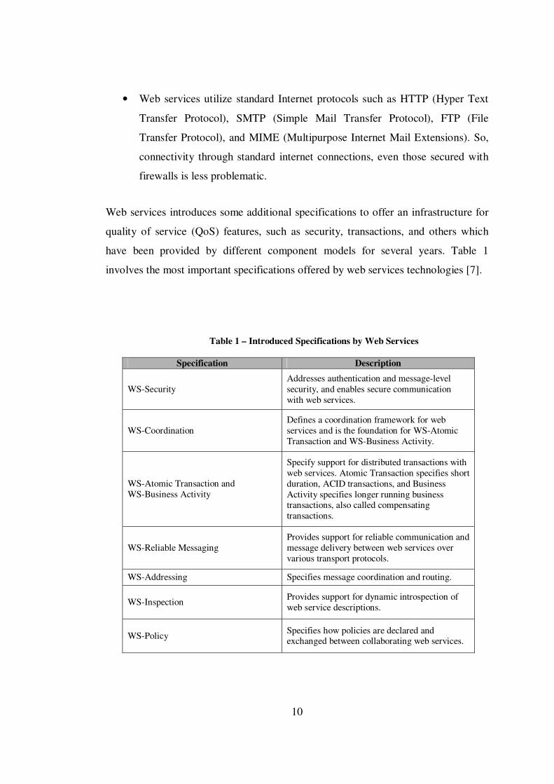
Web services introduces some additional specifications to offer an infrastructure for
quality of service (QoS) features, such as security, transactions, and others which
have been provided by different component models for several years. Table 1
involves the most important specifications offered by web services technologies [7].
Table 1 – Introduced Specifications by Web Services
Specification Description
WS-Security Addresses authentication and message-level security, and enables secure communication with web services.
WS-Coordination Defines a coordination framework for web services and is the foundation for WS-Atomic Transaction and WS-Business Activity.
WS-Atomic Transaction and WS-Business Activity
Specify support for distributed transactions with web services. Atomic Transaction specifies short duration, ACID transactions, and Business Activity specifies longer running business transactions, also called compensating transactions.
WS-Reliable Messaging Provides support for reliable communication and message delivery between web services over various transport protocols.
WS-Addressing Specifies message coordination and routing.
WS-Inspection Provides support for dynamic introspection of web service descriptions.
WS-Policy Specifies how policies are declared and exchanged between collaborating web services.
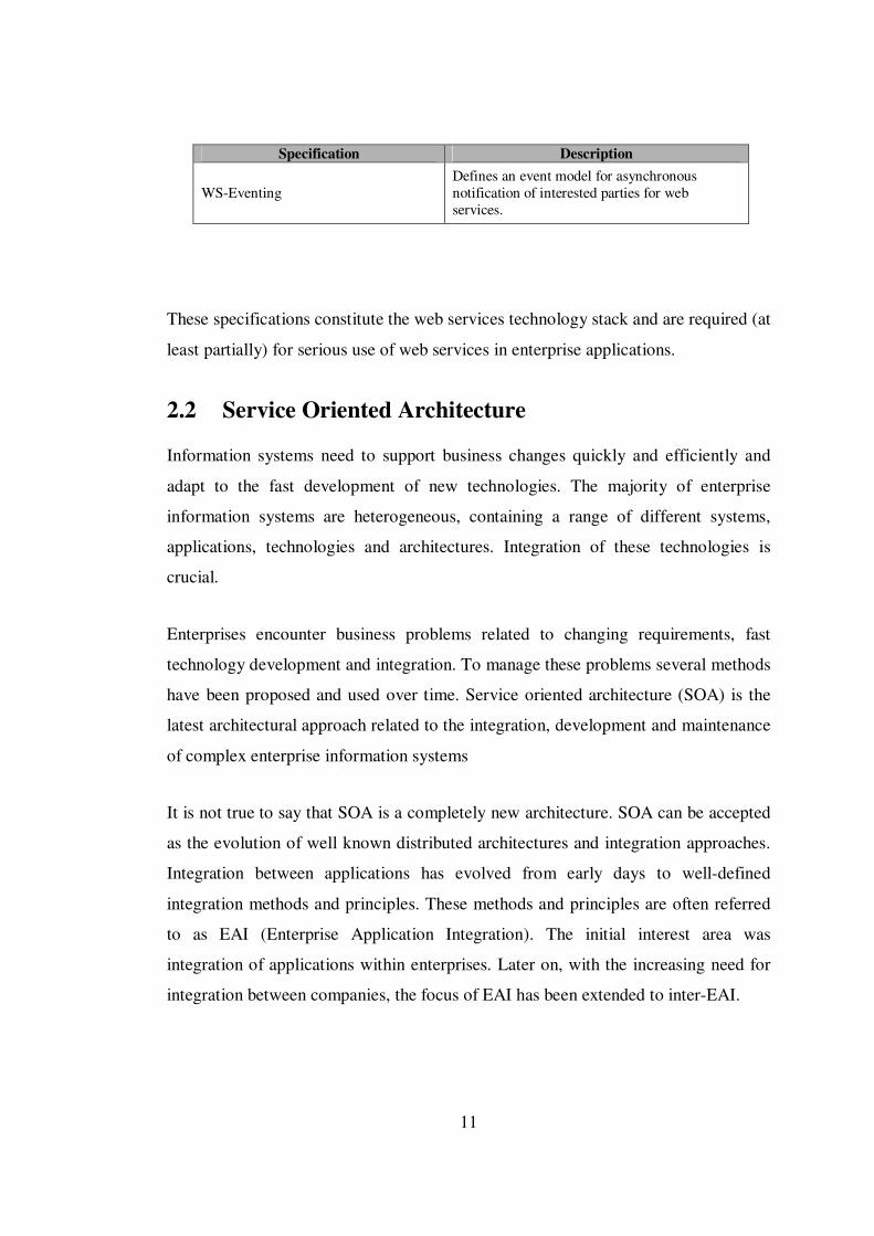
11
Specification Description
WS-Eventing Defines an event model for asynchronous notification of interested parties for web services.
These specifications constitute the web services technology stack and are required (at
least partially) for serious use of web services in enterprise applications.
2.2 Service Oriented Architecture
Information systems need to support business changes quickly and efficiently and
adapt to the fast development of new technologies. The majority of enterprise
information systems are heterogeneous, containing a range of different systems,
applications, technologies and architectures. Integration of these technologies is
crucial.
Enterprises encounter business problems related to changing requirements, fast
technology development and integration. To manage these problems several methods
have been proposed and used over time. Service oriented architecture (SOA) is the
latest architectural approach related to the integration, development and maintenance
of complex enterprise information systems
It is not true to say that SOA is a completely new architecture. SOA can be accepted
as the evolution of well known distributed architectures and integration approaches.
Integration between applications has evolved from early days to well-defined
integration methods and principles. These methods and principles are often referred
to as EAI (Enterprise Application Integration). The initial interest area was
integration of applications within enterprises. Later on, with the increasing need for
integration between companies, the focus of EAI has been extended to inter-EAI.
12
SOA defines the concepts, architecture and process framework, to enable cost-
efficient development, integration and maintenance of information systems through
reduction of complexity and stimulation of integration and reuse. Let us look at the
definition of SOA, as provided in a paper by Bernhard Borges, Kerrie Holley, and
Ali Arsanjani:
SOA is the architectural style that supports loosely coupled services to enable
business flexibility in an interoperable, technology-agnostic manner. SOA consists of
a composite set of business-aligned services that support a flexible and dynamically
re-configurable end-to-end business processes realization using interface-based
service descriptions [8].
2.2.1 SOA Concepts
Although SOA is most often implemented with web services, it is not directly related
to any technology and more than just a set of technologies. Using web services is not
adequate to build SOA. On the other hand it is obvious that web services are the most
appropriate technology for SOA realization.
Table 2 involves the most important SOA concepts [7].
Table 2 – The Most Important SOA Concepts
Concept Description
Services Services provide business functionalities. Each service provides a business value and hides implementation details.
Self-describing interfaces
Service consumers access the service through its interface that defines a set of public operation signatures. Interfaces are the contacts between the service provider and service consumer.
Exchange of messages Operations are defined as a set of messages. Messages specify the data to be exchanged and describe it in a platform and language independent

13
Concept Description way using schemas.
Support for synchronous and asynchronous communication
Service consumers access the service through the service bus. Service consumers can use synchronous or asynchronous communication modes to invoke operations of service. In synchronous mode, a service operation returns a response to the service consumer after the processing is complete. The service consumer has to wait for the completion. In asynchronous mode a service operation does not return a response to the consumer, although it may return an acknowledgement so that the consumer knows that the operation has been invoked successfully.
Loose coupling
Loosely coupled services are services that expose only the necessary dependencies and reduce all kinds of artificial dependencies. This is particularly important when services are subject to frequent changes.
Service registries
To simplify and automate searching for the appropriate service, services are maintained in service registries, which act as directory listings. Service providers publish services in registries; service consumers look up the services in the registries. Lookup can be done by name, service functionality, or business process properties. UDDI is an example of a service registry.
Quality of service
Services usually have associated quality-of-service attributes. Such attributes include security, reliable messaging, transaction, correlation, management, policy, and other requirements. The infrastructure must provide support for these attributes.
Composition of services into business processes
Services are composed in a particular order and follow a set of rules to provide support for business processes. Composition of services allows providing support for business processes in a flexible and relatively easy way. It also enables to modify business processes quickly and therefore provide support to changed requirements faster and with less effort.
14
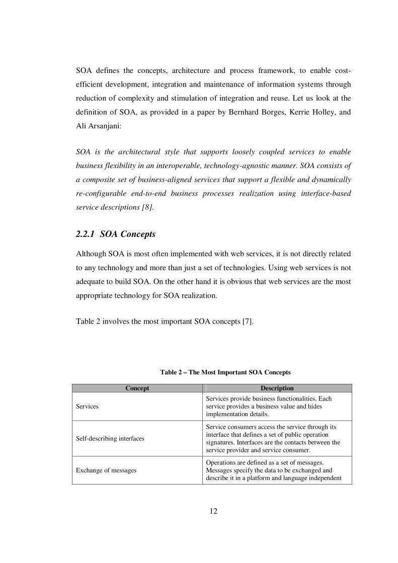
Figure 3 depicts the architectural view of SOA and positions the concepts defined in
Table 2.
Figure 3 – Architectural View of SOA and Positions of Concepts
2.2.2 SOA and Web Services
As an architectural pattern [9], Service Oriented Architecture sketches a fundamental
structural organization schema constituting services, their descriptions and operations
on them such as selection, discovery and binding. Providers, consumers and brokers
are the basic involved roles [10]. SOA decomposes an application or system into
business centric and loosely coupled independent service components, which offer
transactional functionally to other parts of the system. It offers a flexible
infrastructure in which services are playing a fundamental role for dynamically
adopting changing business expectations [11].
Furthermore, SOA provides service registries for advertising services, service
repositories for storing metadata, service definition languages for defining service

15
contracts and service platforms for facilitating design and runtime support for service
creation, deployment, and execution. In SOA, the business processes assume a
major role aiming at developing, composing, orchestrating and managing services in
the context of business services to satisfy business goals [12].
Using SOA in web based applications created a new wave for universal
interoperability. W3C has defined Web service as a software system designed to
support interoperable machine-to-machine interaction over a network [13].
Orchestration of web services supports the coordination of different inter-agency
processes [18]. Web services can be described by using Web Service Description
Language (WSDL), advertised, discovered, composed and interacted via Simple
Access Object Protocol (SOAP). Furthermore, discovery of web services can be
realized by the Universal Description, Discovery and Integration (UDDI) facility.
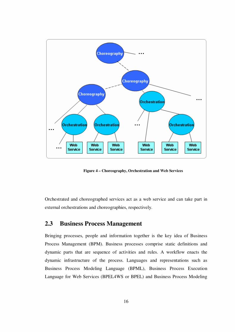
Regarding the composition rules and the sequence of service activations, web
services and composite services form a new composite service. Orchestration and
choreography are two tightly-coupled concepts diverged in the point of using a
central mechanism to activate web services. An orchestration is responsible for
combining and controlling the sequence of web services, whereas collaboration of
each service is defined by choreography in order to achieve a specified target. Figure
4 depicts the view of current orchestration, choreography and web service relations.
16
Figure 4 – Choreography, Orchestration and Web Services
Orchestrated and choreographed services act as a web service and can take part in
external orchestrations and choreographies, respectively.
2.3 Business Process Management
Bringing processes, people and information together is the key idea of Business
Process Management (BPM). Business processes comprise static definitions and
dynamic parts that are sequence of activities and rules. A workflow enacts the
dynamic infrastructure of the process. Languages and representations such as
Business Process Modeling Language (BPML), Business Process Execution
Language for Web Services (BPEL4WS or BPEL) and Business Process Modeling

17
Notation (BPMN) exist, representing different perspectives that are functional,
behavioral, organizational and informational. Functional perspective deals with the
question “what” including the process elements and flows of information entities,
whereas behavioral perspective answers the questions “when” and “how” by
representing the sequence of actions. Organizational perspective specifies “where”
and “by whom” and informational perspective represents produced and modified
entities [14].
Business process management and service oriented architecture depict the business
and IT parts respectively. In order to achieve primary, supporting and organizational
business processes effectively [15], SOA proposes a framework from IT perspective
where processes assume a conceptual role and services realize the logical
infrastructure.
2.3.1 Importance of Business Processes
Enterprise applications and information systems are crucial for companies to perform
their business operations. Enterprise information systems can improve the efficiency
of businesses by automating the business processes. The objective of almost every
company is that the applications it uses should provide comprehensive support for
business processes. This means that applications should align with business
processes closely.
Although this requirement does not sound very difficult to fulfill, the real world
situation shows a different picture. In general, business processes are dynamic
structures. Companies have to adapt their business processes to customers. So these
processes have to be improved, optimized and modified methodically. This can be
done only in an agile manner. Every change and improvement in a business process
has to be reflected in the applications that provide support for them. Only companies
where applications can be quickly and efficiently adapted to the changing business
needs can stay competitive on the global market.
18
It is obvious that changing and modifying applications is a difficult job and requires
time. This means that information systems cannot react instantly to changes in
business processes. They require some time to implement, test, and deploy the
modifications. This time is sometimes referred to as the information systems gap
time [7]. Information systems gap time should be as short as possible. At this point
automation of business processes has importance and for efficient automation of
business processes through IT, there are some necessities.
Providing a standardized way to expose and access the functionality of applications
as services is one of the most important issues. The latest distributed architecture,
which combines both synchronous and asynchronous communications, is Web
Services. Web services are the most suitable distributed architecture for exposing the
functionality of applications as services.
Providing integration architecture between the various services and existing and
newly developed applications used in business processes is the second issue.
Integration between applications is a well known topic. This integration is needed
because enterprise information systems usually consist of several different
applications, which address certain (sometimes isolated) functions and tasks and not
whole business processes. Achieving efficient integration is related to the definition
and realization of sound integration architectures, which are often very complex,
particularly in large companies. Best methods and practices for building integration
architectures are today known as Service Oriented Architectures (SOA) [7].
Finally providing a specialized language for composition of exposed functionalities
of applications into business processes is also needed. The most popular, commonly
accepted, and specialized language for business process definition is Business
Process Execution Language (BPEL). BPEL promises to achieve the holy grail of
enterprise information systems to provide an environment where business processes
can be developed in an easy and efficient manner and quickly adapted to the
changing needs of enterprises without too much effort [7].
19
2.3.2 Business Process Execution Language (BPEL)
As mentioned in the previous section, one of the main goals of business process
automation solutions is to provide a standard and specialized language for composing
services into business processes. Business Process Execution Language (BPEL) is
such a language and is quickly becoming the dominant standard. The main aim of
BPEL is to standardize the process of automation between web services.
Within enterprises, BPEL is used to standardize application integration and between
enterprises, BPEL enables easier and more effective integration with business
partners. Definitions of business processes described in BPEL do not affect existing
systems. BPEL is the key technology in environments where functionalities already
are or will be exposed via web services. With increases in the use of web service
technology, the importance of BPEL will rise further.
IBM, BEA, and Microsoft developed the first version of BPEL in August 2002.
Since then SAP and Siebel have joined, which has resulted in several modifications
and improvements and adoption of version 1.1 in March 2003. In April 2003, BPEL
was submitted to Organization for the Advancement of Structured Information
Standards (OASIS) for standardization purposes, where the Web Services Business
Process Execution Language Technical Committee (WSBPEL TC) has been formed.
Many vendors have joined the WSBPEL TC. This has led to even broader
acceptance in industry [7].
2.3.2.1 Features of BPEL
Simple and complex business processes can be modeled and developed with BPEL.
In fact BPEL is similar to conventional programming languages and focused on the
definition of business processes. Business processes can be defined in an algorithmic
way by using offered constructs such as loops, conditions, variables, assignments,
etc. BPEL is less complex than traditional programming languages and simplifies
learning.
20
The most important BPEL constructs (activities) are related to the activation of web
services. Synchronous and asynchronous invoke operations can be done easily.
Operations can be invoked either in sequence or in parallel. Callbacks can be waited
from web services as results of invoke operations. BPEL provides support for long
running process and compensation. Compensation allows undoing partial works that
has not finished successfully.
Listed below are the most important features that BPEL provides [7].
• Describe the logic of business processes through composition of services.
• Compose larger business processes out of smaller processes and services.
• Handle synchronous and asynchronous (often long running) operation
invocations on services, and manage callbacks that occur at later times.
• Invoke service operations in sequence or parallel.
• Selectively compensate completed activities in case of failures.
• Maintain multiple long running transactional activities, which are also
interruptible.
• Resume interrupted or failed activities to minimize work to be redone.
• Route incoming messages to the appropriate processes and activities.
• Correlate requests within and across business processes.
• Schedule activities based on the execution time and define their order of
execution.
21
• Execute activities in parallel and define how parallel flows merge based on
synchronization conditions.
• Structure business processes into several scopes.
• Handle message related and time related events.
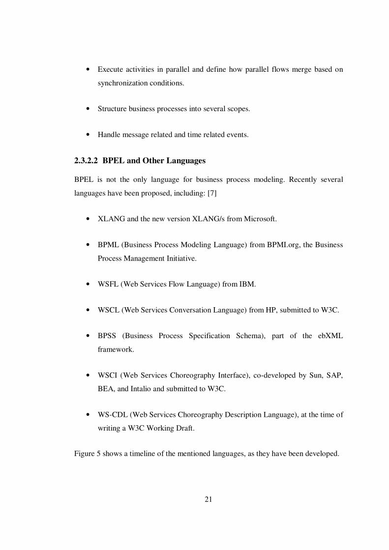
2.3.2.2 BPEL and Other Languages
BPEL is not the only language for business process modeling. Recently several
languages have been proposed, including: [7]
• XLANG and the new version XLANG/s from Microsoft.
• BPML (Business Process Modeling Language) from BPMI.org, the Business
Process Management Initiative.
• WSFL (Web Services Flow Language) from IBM.
• WSCL (Web Services Conversation Language) from HP, submitted to W3C.
• BPSS (Business Process Specification Schema), part of the ebXML
framework.
• WSCI (Web Services Choreography Interface), co-developed by Sun, SAP,
BEA, and Intalio and submitted to W3C.
• WS-CDL (Web Services Choreography Description Language), at the time of
writing a W3C Working Draft.
Figure 5 shows a timeline of the mentioned languages, as they have been developed.
22
Figure 5 – Timeline of Business Process Modeling Languages
2.3.2.3 Developing Business Processes with BPEL
BPEL uses an XML based vocabulary that allows designers to specify and describe
business processes. Business processes defined with BPEL can be also executed by a
BPEL engines. These kinds of processes are referred to as executable processes.
Executable business processes are processes that compose a set of existing services.
When a business process is described in BPEL, a new web service is actually defined
that is a composition of existing services. The interface of the new BPEL composite
web service uses a set of port types, through which it provides operations like any
other web service. To invoke a business process described in BPEL, the resulting
composite web service must be invoked.
In a typical scenario, the BPEL business process receives a request. To fulfill it, the
process then invokes the involved web services and finally responds to the original
caller. Because the BPEL process communicates with other web services, it relies
heavily on the WSDL description of the web services invoked by the composite web
service.

23
CHAPTER 3
3. SYSTEM DESIGN THROUGH PROCESS DECOMPOSITION
3.1 Basics of SOSEML Philosophy
Service Oriented Software Engineering Modeling Language (SOSEML) purposes to
provide a common and acceptable system design approach for SOA based software
development. SOSEML is a graphical modeling language which supports a top down
approach in the engineering of complex business processes. The “divide and
conquer” paradigm is not a new idea to solve complex systems. Both SOSEML and
its ancestor COSEML are based on this idea [16].
When a software system description is given, the proposed methodology aims at
accepting the whole system as a large and complex business process which realizes
the target business goal. From design perspective, it is obvious that modeling a huge
process with all of its details is hard. So, the first step of the modeling activity is
decomposing this complex process (namely the whole system) into high level sub
processes. These high level processes may also be decomposed into different sub
processes too and a decomposition tree is constructed by this way. Processes are
decomposed iteratively until atomic processes are reached. An atomic process is a
process that does not include any sub process. In SOSEML, these are accepted as
existing web services residing at the leaf level of the decomposition tree.
In SOSEML, highest level processes are the most abstract part of the decomposition;
intermediate processes represent the processes which are required by parent
processes and finally, leaf level processes are the web services. Parent process
includes the children processes and coordinates the relationships among the children
that are connected utilizing material flow, resource allocation, and synchronization

24
kinds of connections. Processes can also store the variables and other execution
parameters (such as some return values from service calls, and parameters to be sent
to other service calls). State management can be maintained at least by managing
local data structures. Processes basically give the ordering information for service
activation. The orchestration of the children processes can be represented using
Business Process Execution Language (BPEL). By using this language, the ordering
of web service activations and saving the intermediate states are achieved. A process
itself can be deployed as a web service; it can serve other processes. A web service
can publish various methods in its interface where some of those methods can be
used in different processes. Therefore, in SOSEML, a web service can have more
than one web service interface too. Web service interfaces specify the methods that
can be called, input and output values may occur in conversations and ordering of
method calls [17].
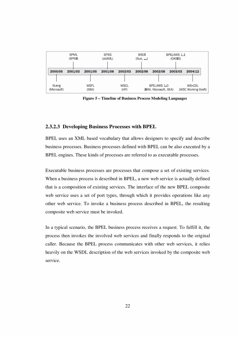
For all methodologies, the offered models represent the three dimensions of software
systems namely data, function and structure (and sometimes the fourth: control).
Traditional approaches have disjoint graphical models for different cross sections of
the system based on data, function, and structure. In object oriented approaches, the
mentioned dimensions are represented in combination [3].
In traditional methodologies, the units subject to decomposition were functions or
modules. So, a “functional” decomposition of the system was essential. With object
oriented principles the decomposition units changed to abstract classes which bundle
the state variables and operations into entities called objects. In object oriented
methodologies software systems were decomposed with respect to “data”. After the
introduction of modular design and development notions, component based
methodologies used a “structure” oriented decomposition approach. A service
oriented methodology has to be again “procedural” (functional) more than any other
aspect.
25
Figure 6 – Modeling Emphasis for Different Approaches (Adapted from [3])
Figure 6 depicts the modeling emphasis on different dimensions, for different
approaches. As a service oriented modeling language, for SOSEML, the modeling
emphasis is in the functional (procedural) dimension. In a SOSEML decomposition
tree, the components of the model correspond to abstract processes which can be
defined only in a procedural way. On the other hand in COSEML, the decomposition
was fully structural. The system is decomposed into packages that can be thought of
as building blocks. Each block can contain further sub blocks. This structural
decomposition continues until all sub blocks are decomposed into components. From
this perspective, SOSEML is in a different dimension than its ancestor naturally.

26
3.2 Modeling with SOSEML
Modeling a service oriented architecture based software system with SOSEML
consists of basically two main steps:
• Constructing a hierarchical decomposition tree
• Creating process models for each process in decomposition tree
In the first step, the whole software system is accepted as a single and large business
process. First level sub processes are determined and the whole system is
decomposed into smaller sub processes. This hierarchical decomposition is done
iteratively for each sub process and eventually web services are determined at the
leaf level of the tree.
When the first step of the modeling activity is completed, the general structure of the
model is produced. Main processes and sub processes which are parts of larger
parent processes are determined and defined. In the second step of the modeling
activity, to obtain a complete and detailed model, all processes in decomposition tree
are modeled with a business process definition language. Leaf level processes use the
existing web services and interactions between these services and the process are
defined in the business flows. Intermediate and top level processes use other sub
processes in decomposition tree. So, business flows for these kinds of processes
include the relations between the sub processes and the main process. For all
processes in decomposition tree, BPEL is used to create complete business process
models.
Following sub sections of this chapter describe the concepts of SOSEML and steps
of modeling activity with SOSEML in detail.

27
3.2.1 SOSEML Notation
SOSEML is a completely graphical modeling language. In the first step of modeling
activity four basic graphical modeling elements are used in SOSEML to construct a
hierarchical decomposition tree.
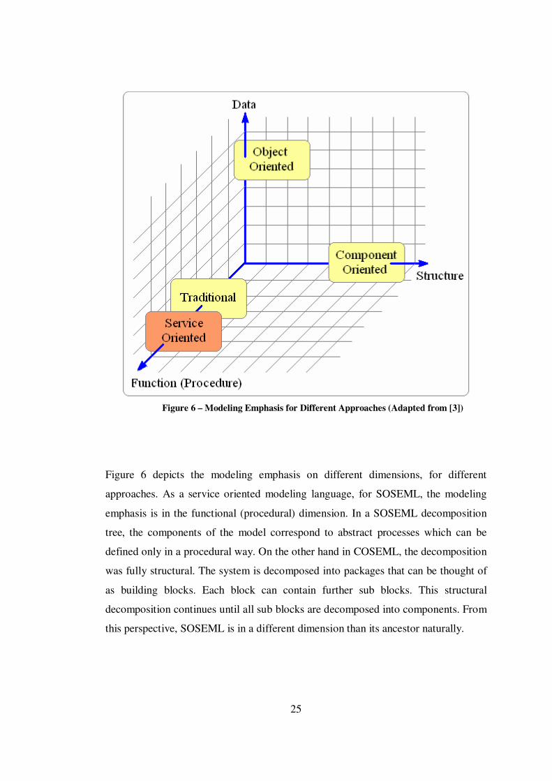
Graphical modeling elements in SOSEML are depicted in Figure 7.
Figure 7 – Graphical Modeling Elements in SOSEML
28
Process, Web Service, Interface and Link symbols (respectively drawn in Figure 7)
are the basic graphical modeling elements in SOSEML.
A process is represented by a yellow package symbol with a small process icon on
the left upper corner. Processes are the main building blocks in a decomposition tree.
The whole system and all sub processes are shown by process symbols in the model.
Web services are represented by orange boxes. The small icon on the right corner of
the box implies that a web service is a remote component. A web service can publish
various methods or operations in its interface where some of those methods can be
used in different processes. Therefore, in SOSEML, a web service can have more
than one web service interface. Names of all interfaces belong to the web service are
also shown in the box symbol.
Web service interfaces are also shown in SOSE models and represented by orange
boxes similar to web service symbols. An interface symbol contains the names of the
operations which can be called by the requesters through this interface.
Processes, web services and web service interfaces are the building blocks in a SOSE
model. On the other hand, links form a skeleton, connecting the set of blocks for
producing the target system. Links are represented by standard black lines in the
model and are used to connect other graphical elements. A link symbol can be used
between a process and another process or between a process and a web service.
Interfaces belong to a web service are also connected to service by using link
symbols.
As mentioned in the previous section, after building a decomposition tree by using
the graphical elements described above, the second step of the modeling activity is
creating process models for each process. To fulfill it, BPEL is used as a process
modeling language.

29
Although BPEL is completely an XML based language, some graphical editors can
be used to create a complete BPEL process model with correct syntax. In SOSEML,
all process models are also created and designed graphically using the exact BPEL
syntax.
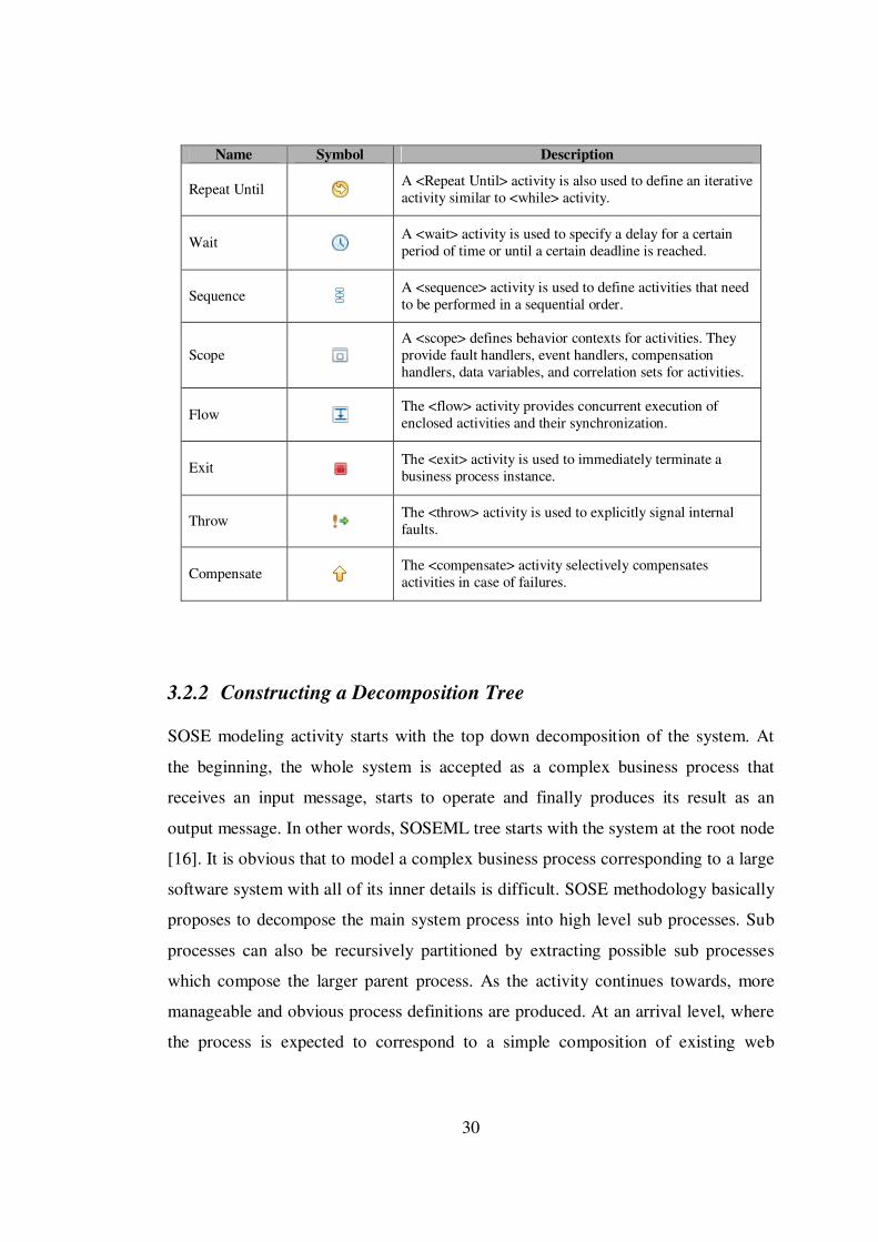
Table 3 involves the basic graphical elements which are used to design BPEL
process models in SOSEML.
Table 3 – BPEL Symbols Used in SOSEML
Name Symbol Description
Invoke The <invoke> activity is used to invoke the web service operations provided by partners.
Receive A <receive> activity is used to receive requests in a BPEL business process to provide services to its partners.
Reply A <reply> activity is used to send a response to a request previously accepted through a <receive> activity.
Assign
The <assign> activity is used to copy data from one variable to another and construct and insert new data using expressions and literal values.
Empty An activity that does nothing is defined by the <empty> tag.
If The <if> activity expresses a conditional behavior.
Pick
The <pick> activity is used to wait for the occurrence of one of a set of events and then perform an activity associated with the event.
While
A <while> activity is used to define an iterative activity. The iterative activity is performed until the specified Boolean condition no longer holds true.
For Each A <For Each> activity is also used to define iterative activities over a counter value for a group of items.
30
Name Symbol Description
Repeat Until A <Repeat Until> activity is also used to define an iterative activity similar to <while> activity.
Wait A <wait> activity is used to specify a delay for a certain period of time or until a certain deadline is reached.
Sequence A <sequence> activity is used to define activities that need to be performed in a sequential order.
Scope
A <scope> defines behavior contexts for activities. They provide fault handlers, event handlers, compensation handlers, data variables, and correlation sets for activities.
Flow The <flow> activity provides concurrent execution of enclosed activities and their synchronization.
Exit The <exit> activity is used to immediately terminate a business process instance.
Throw The <throw> activity is used to explicitly signal internal faults.
Compensate The <compensate> activity selectively compensates activities in case of failures.
3.2.2 Constructing a Decomposition Tree
SOSE modeling activity starts with the top down decomposition of the system. At
the beginning, the whole system is accepted as a complex business process that
receives an input message, starts to operate and finally produces its result as an
output message. In other words, SOSEML tree starts with the system at the root node
[16]. It is obvious that to model a complex business process corresponding to a large
software system with all of its inner details is difficult. SOSE methodology basically
proposes to decompose the main system process into high level sub processes. Sub
processes can also be recursively partitioned by extracting possible sub processes
which compose the larger parent process. As the activity continues towards, more
manageable and obvious process definitions are produced. At an arrival level, where
the process is expected to correspond to a simple composition of existing web

31
services, the decomposition activity can be stopped. Finally these web services are
also connected to the leaf level process to indicate the uses relationship. If desired,
different service interfaces can also be shown at the bottom of the decomposition
tree.
General structure of a decomposition tree in SOSEML notation is depicted in Figure
8.

32
Figure 8 – General Structure of a Decomposition Tree in SOSEML Notation
System_Process is decomposed into tree sub processes: Sub_Process_1,
Sub_Process_2 and Sub_Process_3. These three sub processes operate together
either in sequence or in parallel to produce a result for their parent process. In other
words, System_Process consists of three different sub processes to realize its

33
business goal. Sub_Process_1 is also decomposed into two different processes:
Sub_Process_4 and Sub_Process_5. These two processes are the leaf level processes
in decomposition tree and they do not include any more sub processes.
Sub_Process_5 uses two web services: Web Service1 and Web Service2 to achieve
its business. Web Service1 has two different interfaces used by Sub_Process_5 for
different aims: Interface1 and Interface2. Interface1 includes only one operation and
Interface2 includes two different operations. Probably all of these operations are
called by the Sub_Process_5 during the inner business flow.
Leaf level processes of decomposition tree only use existing web services. In the
process models of these kinds of processes, web service interactions, data flow
mechanisms and variable assignments are defined in an algorithmic way by using
BPEL notations. At this level, the key point of the process models is orchestration of
web services.
On the other hand, the root process (namely the whole system process) and other
intermediate processes are consists of sub processes defined in decomposition tree.
In general case, process models for these high level processes do not directly contain
web service interactions. At these higher levels, process models basically aims to
expose the choreography of sub processes. However, in SOSEML, when a sub
process is completely modeled with BPEL, a new web service (a composite web
service) is created. So, a process itself can be deployed as a web service; it can serve
other processes. From this perspective, for each level of decomposition tree, all
processes can be modeled as BPEL processes.
The following section describes the details of process modeling phase of SOSE
modeling approach.
34
3.2.3 Modeling Processes in Decomposition Tree
The second step of modeling activity is designing business process models for each
process in decomposition tree. Business process models are used to define the initial
details of the business flow in an algorithmic way. Ordering information for service
and sub process activations, synchronous and asynchronous service calls, required
variable and message definitions, exception handling mechanisms and all other
issues to manage the business flow are defined in detail.
3.2.3.1 Process Modeling Basics
In SOSE methodology, XML based standard BPEL specifications are used to model
business processes. Each BPEL process receives a request (generally in a message
format) to start to operate, then invokes the involved web services and finally
responds to the caller.
In a BPEL process model, operations of a web service can be invoked either
synchronously or asynchronously. For synchronous service operations, sender sends
a request message and waits for the reply. On the other hand, for asynchronous
operations, the sender is not blocked after the request. Result of the operation is sent
back to the caller by usually performing callbacks. Since each modeled business
process is exposed as a new web service, In SOSE methodology, a BPEL process
itself can be synchronous or asynchronous. After decomposing the system into sub
processes, the type of the BPEL processes chosen for modeling these processes is
crucial. Long running processes in decomposition tree should be modeled as
asynchronous BPEL processes. However, there may be processes that execute in a
relatively short time. Besides, in some cases, modeler may want the client (caller) to
wait for completion of a service call or sub process. Such processes are modeled as
synchronous.
As mentioned in the previous sections, decomposition of the software system is done
in a top down manner and all sub processes composing the whole system is exposed
35
in several abstraction levels. After constructing a decomposition tree, it is also
crucial to decide which process to start from to model the processes in the tree. At
this point SOSE methodology offers to start from leaf level processes and continue
towards the high level processes and finally model the root process.
Leaf level processes interact with only existing web services and they do not contain
any more sub processes. All operations, input parameters and return values for these
web services are defined in the service WSDL files. So, modeling these leaf level
and relatively simple processes at first is a good starting point.
On the other hand, intermediate and high level processes in decomposition tree
comprise other sub processes. Sub processes are used as newly created web services
by parent processes. So, before starting to model a parent process, its child processes
should be modeled. Interactions between different sub processes and parent process
can be achieved only by this way during modeling activity.
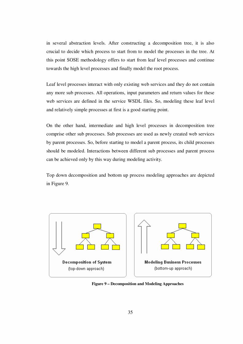
Top down decomposition and bottom up process modeling approaches are depicted
in Figure 9.
Figure 9 – Decomposition and Modeling Approaches
36
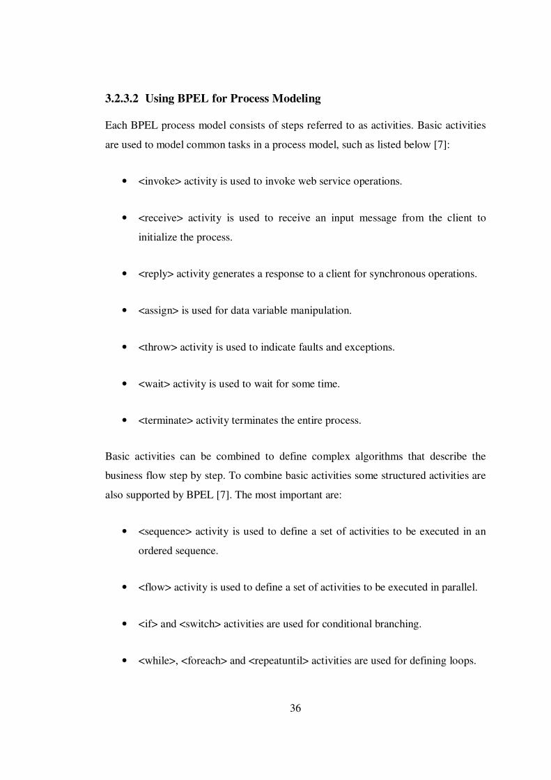
3.2.3.2 Using BPEL for Process Modeling
Each BPEL process model consists of steps referred to as activities. Basic activities
are used to model common tasks in a process model, such as listed below [7]:
• <invoke> activity is used to invoke web service operations.
• <receive> activity is used to receive an input message from the client to
initialize the process.
• <reply> activity generates a response to a client for synchronous operations.
• <assign> is used for data variable manipulation.
• <throw> activity is used to indicate faults and exceptions.
• <wait> activity is used to wait for some time.
• <terminate> activity terminates the entire process.
Basic activities can be combined to define complex algorithms that describe the
business flow step by step. To combine basic activities some structured activities are
also supported by BPEL [7]. The most important are:
• <sequence> activity is used to define a set of activities to be executed in an
ordered sequence.
• <flow> activity is used to define a set of activities to be executed in parallel.
• <if> and <switch> activities are used for conditional branching.
• <while>, <foreach> and <repeatuntil> activities are used for defining loops.
37
• <pick> is used to select one of a number of possible paths.
Apart from the activities listed above, each BPEL process defines partner links by
using <partnerLink> and declares some variables by using <variables>. Partner links
are used to specify relations between several web services in the business process.
Variables are used to store messages exchanged between partners or to hold data that
relates to the state of the process.
To provide an idea how a BPEL process is declared using XML syntax, a simple
asynchronous process definition example is given below. The sample process is
named as LibrarySeacrhProcess and simply uses a single web service for searching a
book in a library.
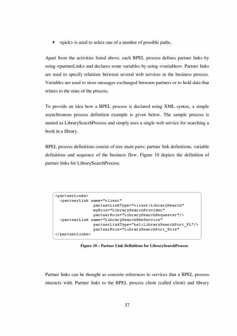
BPEL process definitions consist of tree main parts: partner link definitions, variable
definitions and sequence of the business flow. Figure 10 depicts the definition of
partner links for LibrarySearchProcess.
Figure 10 – Partner Link Definitions for LibrarySearchProcess
Partner links can be thought as concrete references to services that a BPEL process
interacts with. Partner links to the BPEL process client (called client) and library
38
search web service are defined using <partnerLink> tag nested within the
<partnerLinks> element as shown above. For each partner link myRole attribute
indicates the role of the BPEL process and partnerRole attribute indicates the role of
the partner. For asynchronous interactions both roles have to be defined. Since
library search web service is used for a synchronous method call, only the
partnerRole attribute is defined. Partner link types declare how two parties interact
and what each party offers. Partner link type definitions are declared in the WSDL
files of BPEL processes.
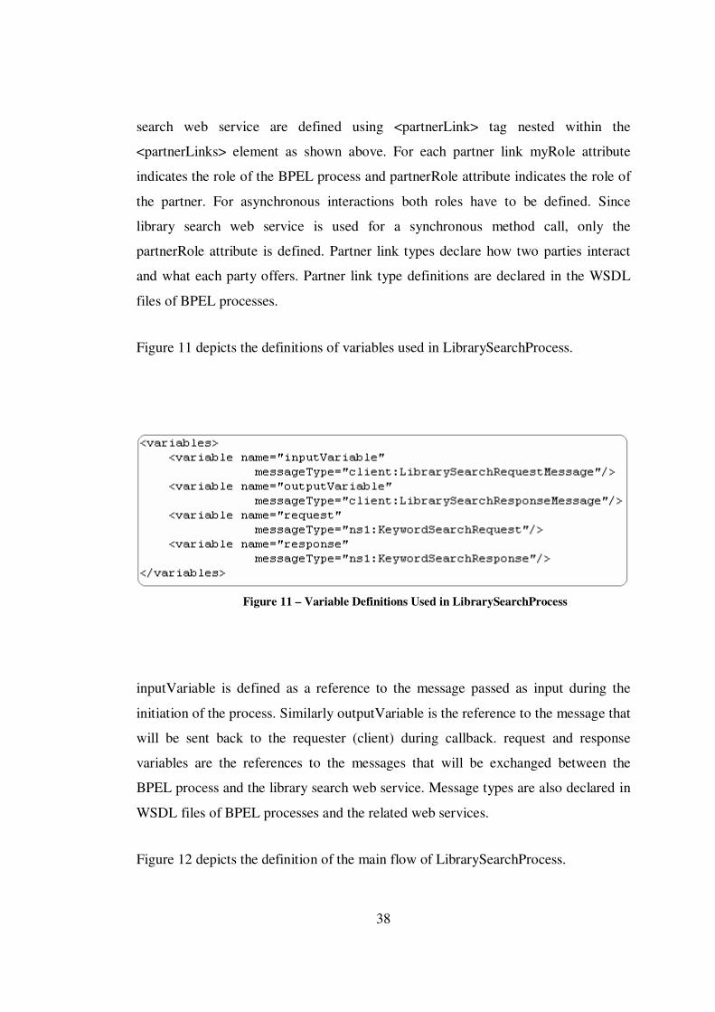
Figure 11 depicts the definitions of variables used in LibrarySearchProcess.
Figure 11 – Variable Definitions Used in LibrarySearchProcess
inputVariable is defined as a reference to the message passed as input during the
initiation of the process. Similarly outputVariable is the reference to the message that
will be sent back to the requester (client) during callback. request and response
variables are the references to the messages that will be exchanged between the
BPEL process and the library search web service. Message types are also declared in
WSDL files of BPEL processes and the related web services.
Figure 12 depicts the definition of the main flow of LibrarySearchProcess.

39
Figure 12 – Definition of the Flow of LibrarySearchProcess
Between <sequence> tags, the main body where the actual flow of business process
is defined presents. LibrarySearchProcess is initiated with a request message.
Receive activity at the beginning of the flow is used to receive this message with an
input variable. Then an assign activity is used to copy the contents of input variable
to the request variable that will be sent to the library search web service. Invoke
activity is used to invoke the KeywordSearchRequest operation of the web service.

40
The return value in response variable is copied to output variable using another
assign activity. Finally another invoke activity is used to produce a result to the
client.
A graphical representation of this flow is also depicted in Figure 13.
Figure 13 – Graphical Representation of LibrarySearchProcess Flow
For this simple business flow, only basic BPEL activities are included such as
<receive>, <invoke> and <assign>. But most real-world processes are much more
complex and more complicated algorithms should be designed to describe the
business. In these cases, designers need to use other BPEL activities too. For detailed
41
information about the XML syntaxes of other BPEL activities, WS-BPEL 2.0
specification can be seen.
Each modeled BPEL process is also a new web service that can serve other
processes. So, BPEL processes also need WSDL documents too. As mentioned, A
BPEL process is usually started by a client that invokes an operation. Within the
BPEL process files, the interface for this operation is specified. All message types,
operations and port types the process offers to other partners are also defined.
42
CHAPTER 4
4. SOSE MODELING TOOL
4.1 Implementation of SOSECASE
SOSECASE is a graphical modeling tool for SOA based system design and modeling
and it supports the SOSEML notation described in detail in the previous chapter. In
this thesis study, SOSECASE is coded in java and Eclipse SDK 3.2.0 is used as the
development environment. The tool provides easy-to-use and completely graphical
modeling interfaces to the users for constructing system decomposition trees and
creating exact BPEL process models.
New SOSE models can be created, edited and saved using SOSECASE. Most of the
graphical modeling concepts offered by different commercial tools such as UML
editors are included in the tool. Basic graphical modeling activities such as dragging
and dropping graphical elements, editing features such as cut, copy, paste, delete and
find operations are supported by SOSECASE.
SOSECASE uses the Eclipse’s BPEL Designer plug-in for modeling BPEL
processes graphically. This plug-in is completely an open source product and
externally integrated to the main tool by using Eclipse’s RCP (Rich Client Platform)
architecture. The BPEL editor used in SOSECASE produces pure BPEL 2.0 codes
(files with extensions .bpel and .wsdl which include the whole process model
description). BPEL process models designed in SOSECASE can be used in
anywhere else and by any other editor that supports BPEL 2.0 specifications.
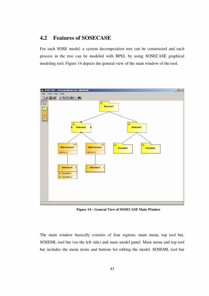
43
4.2 Features of SOSECASE
For each SOSE model, a system decomposition tree can be constructed and each
process in the tree can be modeled with BPEL by using SOSECASE graphical
modeling tool. Figure 14 depicts the general view of the main window of the tool.
Figure 14 – General View of SOSECASE Main Window
The main window basically consists of four regions; main menu, top tool bar,
SOSEML tool bar (on the left side) and main model panel. Main menu and top tool
bar includes the menu items and buttons for editing the model. SOSEML tool bar

44
includes the graphical modeling elements that can be dragged over the model panel
and finally, model panel includes the whole decomposition tree that is being
modeled.
Following sub sections describe the usage of these regions.
4.2.1 Menu Operations
Figure 15 depicts the inner menu items of the main menu.
Figure 15 – Inner Menu Items of SOSECASE Main Menu
A new SOSE model can be created by choosing “New” menu item from File menu.
Existing models can be opened, saved, saved with a new name and printed by
choosing “Open”, “Save”, “Save As” and “Print” menu items respectively. When the
“Exit” menu item is chosen, the tool is closed.
From View menu, automatic layout mode or manual layout modes can be selected. In
automatic layout mode, after each operation (such as insertion or deletion of a node),
the balanced structure of the tree in model panel is always saved by adjusting the
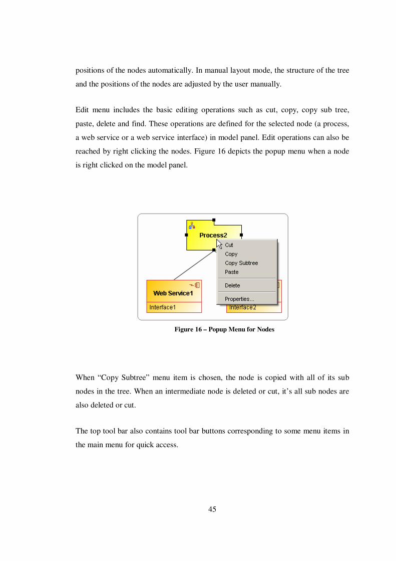
45
positions of the nodes automatically. In manual layout mode, the structure of the tree
and the positions of the nodes are adjusted by the user manually.
Edit menu includes the basic editing operations such as cut, copy, copy sub tree,
paste, delete and find. These operations are defined for the selected node (a process,
a web service or a web service interface) in model panel. Edit operations can also be
reached by right clicking the nodes. Figure 16 depicts the popup menu when a node
is right clicked on the model panel.
Figure 16 – Popup Menu for Nodes
When “Copy Subtree” menu item is chosen, the node is copied with all of its sub
nodes in the tree. When an intermediate node is deleted or cut, it’s all sub nodes are
also deleted or cut.
The top tool bar also contains tool bar buttons corresponding to some menu items in
the main menu for quick access.
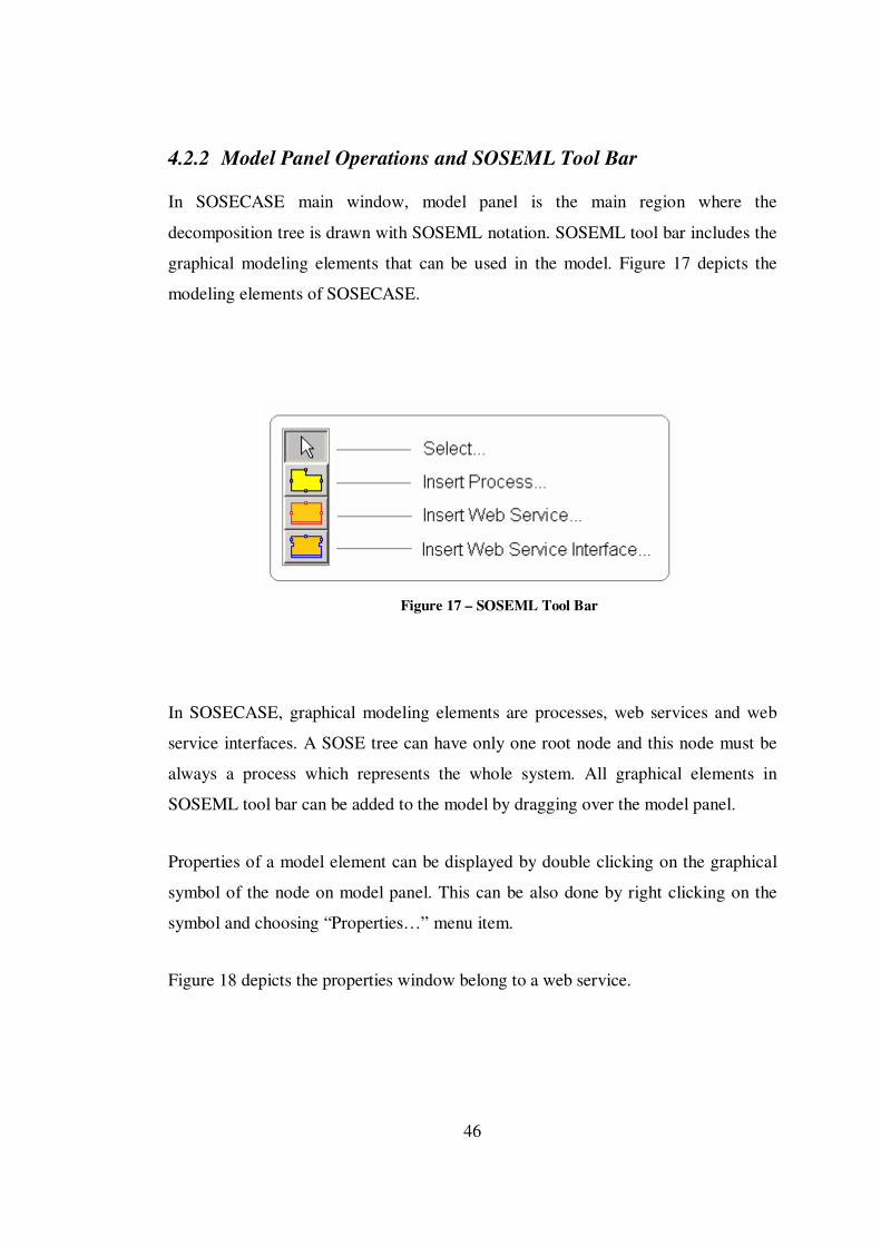
46
4.2.2 Model Panel Operations and SOSEML Tool Bar
In SOSECASE main window, model panel is the main region where the
decomposition tree is drawn with SOSEML notation. SOSEML tool bar includes the
graphical modeling elements that can be used in the model. Figure 17 depicts the
modeling elements of SOSECASE.
Figure 17 – SOSEML Tool Bar
In SOSECASE, graphical modeling elements are processes, web services and web
service interfaces. A SOSE tree can have only one root node and this node must be
always a process which represents the whole system. All graphical elements in
SOSEML tool bar can be added to the model by dragging over the model panel.
Properties of a model element can be displayed by double clicking on the graphical
symbol of the node on model panel. This can be also done by right clicking on the
symbol and choosing “Properties…” menu item.
Figure 18 depicts the properties window belong to a web service.
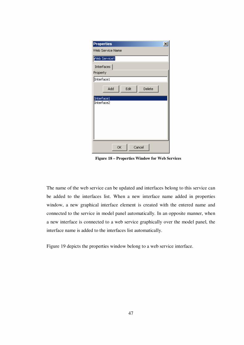
47
Figure 18 – Properties Window for Web Services
The name of the web service can be updated and interfaces belong to this service can
be added to the interfaces list. When a new interface name added in properties
window, a new graphical interface element is created with the entered name and
connected to the service in model panel automatically. In an opposite manner, when
a new interface is connected to a web service graphically over the model panel, the
interface name is added to the interfaces list automatically.
Figure 19 depicts the properties window belong to a web service interface.

48
Figure 19 – Properties Window for Web Service Interfaces
Web service interface name can be updated in properties window. Names of the
operations which can be called through this interface are listed in methods-in list.
SOSECASE does not force the modeler to create the detailed BPEL model for a
newly added process at that moment. Namely, at any moment, in decomposition tree,
a process might have been modeled with BPEL. Besides, there might be processes
whose BPEL processes have not been created yet too. These two kinds of processes
are shown differently in the model panel. Figure 20 depicts the graphical
representations of processes in decomposition tree.
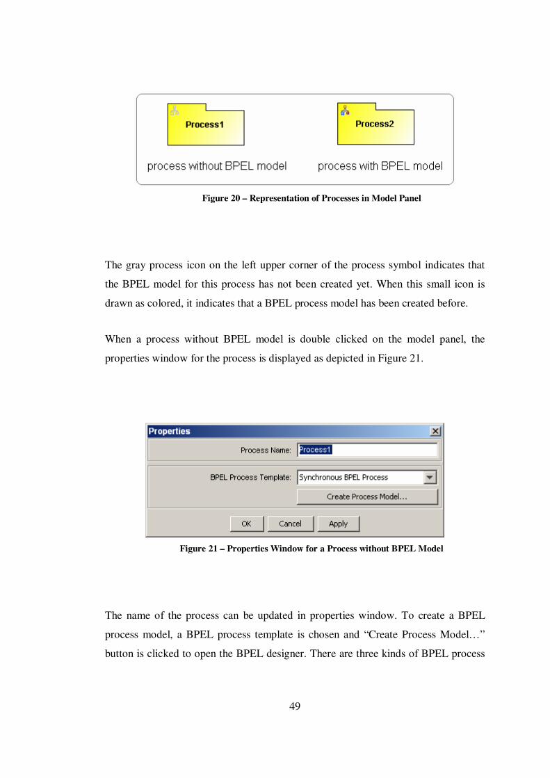
49
Figure 20 – Representation of Processes in Model Panel
The gray process icon on the left upper corner of the process symbol indicates that
the BPEL model for this process has not been created yet. When this small icon is
drawn as colored, it indicates that a BPEL process model has been created before.
When a process without BPEL model is double clicked on the model panel, the
properties window for the process is displayed as depicted in Figure 21.
Figure 21 – Properties Window for a Process without BPEL Model
The name of the process can be updated in properties window. To create a BPEL
process model, a BPEL process template is chosen and “Create Process Model…”
button is clicked to open the BPEL designer. There are three kinds of BPEL process

50
templates: synchronous, asynchronous and empty. The meanings of these templates
are described in the following section.
When a process whose BPEL process model has been created before is double
clicked on the model panel, the properties window is displayed as depicted in Figure
22.
Figure 22 – Properties Window for a Process with BPEL Model
In this case, the name of the BPEL process file that has been created before is shown
in properties window. The name of the BPEL file is always as same as the name of
the process. Namely, when a process is renamed, the name of the file is also
renamed. The existing BPEL model can be viewed and updated in BPEL designer by
clicking “Open Process Model…” button.
4.3 BPEL Designer
SOSECASE uses an external BPEL designer to create and edit BPEL process models
for the processes in the constructed decomposition tree.
As mentioned before, a BPEL process template is chosen when a new BPEL process
model is created for a process. A BPEL process model can be created as

51
synchronous, asynchronous or empty. Figure 23 depicts the structures of these
templates.
Figure 23 – BPEL Process Templates
When a BPEL process model is created with a synchronous template, <receive> and
<reply> activities are automatically included. The process is started with a
synchronous request message and the result of the process is returned with a reply.
For asynchronous templates, an <invoke> activity (callbackClient) is placed instead
of <reply>. The result of the process is notified by calling (invoking) a callback
method from the client. Empty templates do not include any activity initially.
Figure 24 depicts the general view of BPEL designer.

52
Figure 24 – General View of BPEL Designer
Main window of BPEL designer consists of five functional regions; process model
panel in the middle, a palette for the activities on the left, process contents panel on
the right and activity properties page at the bottom of the window.
Activities which can be added to a BPEL process model are listed in the palette in
three groups. Actions are the basic BPEL activities such as <invoke>, <receive>,
<reply> and <assign> which represent the basic constructs and are used for common
tasks in business flow. Controls are the structured activities such as <if>, <while>,
<scope> and <flow>. These algorithmic activities are used to combine and manage
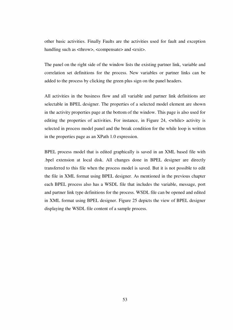
53
other basic activities. Finally Faults are the activities used for fault and exception
handling such as <throw>, <compensate> and <exit>.
The panel on the right side of the window lists the existing partner link, variable and
correlation set definitions for the process. New variables or partner links can be
added to the process by clicking the green plus sign on the panel headers.
All activities in the business flow and all variable and partner link definitions are
selectable in BPEL designer. The properties of a selected model element are shown
in the activity properties page at the bottom of the window. This page is also used for
editing the properties of activities. For instance, in Figure 24, <while> activity is
selected in process model panel and the break condition for the while loop is written
in the properties page as an XPath 1.0 expression.
BPEL process model that is edited graphically is saved in an XML based file with
.bpel extension at local disk. All changes done in BPEL designer are directly
transferred to this file when the process model is saved. But it is not possible to edit
the file in XML format using BPEL designer. As mentioned in the previous chapter
each BPEL process also has a WSDL file that includes the variable, message, port
and partner link type definitions for the process. WSDL file can be opened and edited
in XML format using BPEL designer. Figure 25 depicts the view of BPEL designer
displaying the WSDL file content of a sample process.
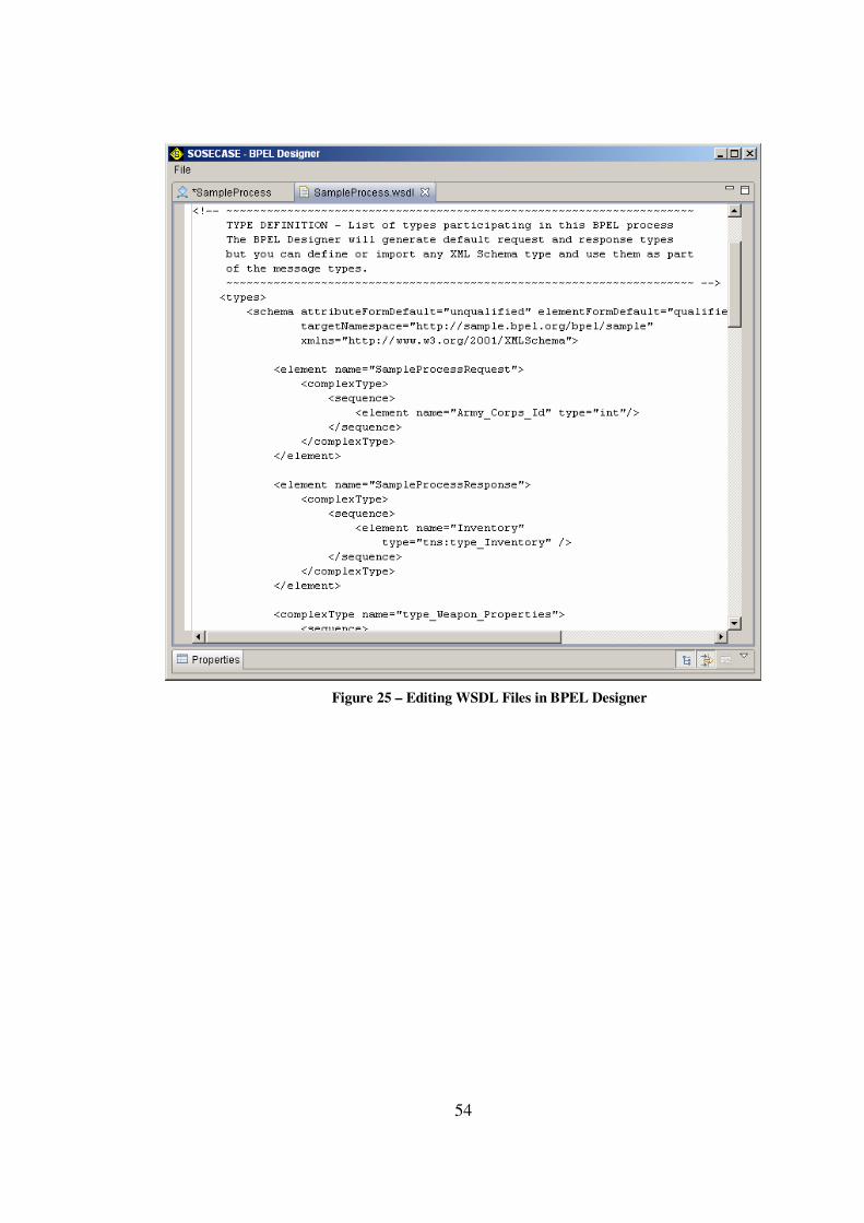
54
Figure 25 – Editing WSDL Files in BPEL Designer
55
CHAPTER 5
5. A CASE STUDY: MODELING A MILITARY DEPLOYMENT PLANNING SYSTEM
In the last chapter of the thesis report, a SOA based software system is modeled with
SOSEML to demonstrate the basics of the proposed modeling approach. The aim of
this case study is not to develop a completed and running software. It is intended to
analyze the system and create a detailed model with its all algorithmic details to
show the steps of the modeling activity in SOSE modeling technique. Web services
used in the study are not the existing services. They are just supposed to be existed in
the solution domain.
In the following sub sections, SOSE modeling activity is described through an
example software which is named as military deployment planning. First the
requirements of the software are described briefly, and then SOSE model for the
system is created step by step.
5.1 Description of the System Concepts
Military deployment planning is needed to produce military plans for the deployment
of a series of weapons and sensors. Deployment plans are used during the air defense
operations for some critical military regions such as harbors and strategically
important geographical zones.
Air defense activities for a geographical region are basically performed by a set of
sensors, weapons and an operation center. Sensors that may have different working
properties are used as radar units and placed at suitable locations in the region for
tracking the air. The track information belong to air vehicles obtained by different
sensors is sent to operation center. Track identification and classification evaluations

56
are done by the operation center and suitable weapons positioned in the defense zone
are engaged to the enemy targets when needed.
Before the air defense activities start, a deployment plan should be prepared to be
ready for the operational work. A deployment plan basically includes the placement
information and task orders for the weapon and sensor units and the battlefield
geometries inside the defense region.
Placements of the units in the geographical terrain are crucial. Weapons should be
placed to the correct defense positions according to their operational working
properties such as target prevention and range capabilities. Sensors that may have
different radiation and coverage properties should be placed to the suitable locations
for the best tracking. Some geographical constraints should be also considered for the
placements of sensors. If possible, GIS (Geographical Information Systems) based
analyses may be used for determination of the correct placements such as visibility
and coverage analyses.
Unit task orders for the weapons and sensors should be also assigned before the
operational work. Primary target lines of the weapons and radiation segments for the
sensors are the needed task orders for air defense operations. Primary target line of a
weapon indicates the direction information that the weapon will be rotated to.
Namely, a weapon is responsible for the prevention of enemy attacks that may come
from its primary target line. On the other hand, sensor radiation segments indicate the
sector regions that the sensor is responsible to track. According to the working
properties of a sensor, it may track a full circle region (a 360 degree horizontal
coverage) or several separate sectors. Figure 26 depicts the graphical representations
of primary target line and radiation segments for a weapon and sensor respectively.

57
Figure 26 – Primary Target Line and Radiation Segments for Weapons and Sensors
Battlefield geometries are also included in a deployment plan in addition to the
placement and task order information of units. Battlefield geometries are the three
dimensional visual geometries which can be defined for air and land area. These
geometries can be defined as a circle, polygon, corridor or a line. Geometries defined
for the air area are generally used for the identification evaluation for the tracks. For
example, when a track passes through a prohibited corridor, it is evaluated as a
probable hostile track. Geometries defined for the land area are used to mark some
critic areas for the operation such as minefields, restricted zones and airfields. These
geometries are valid for some specified time periods and are defined by the air and
land forces continuously.
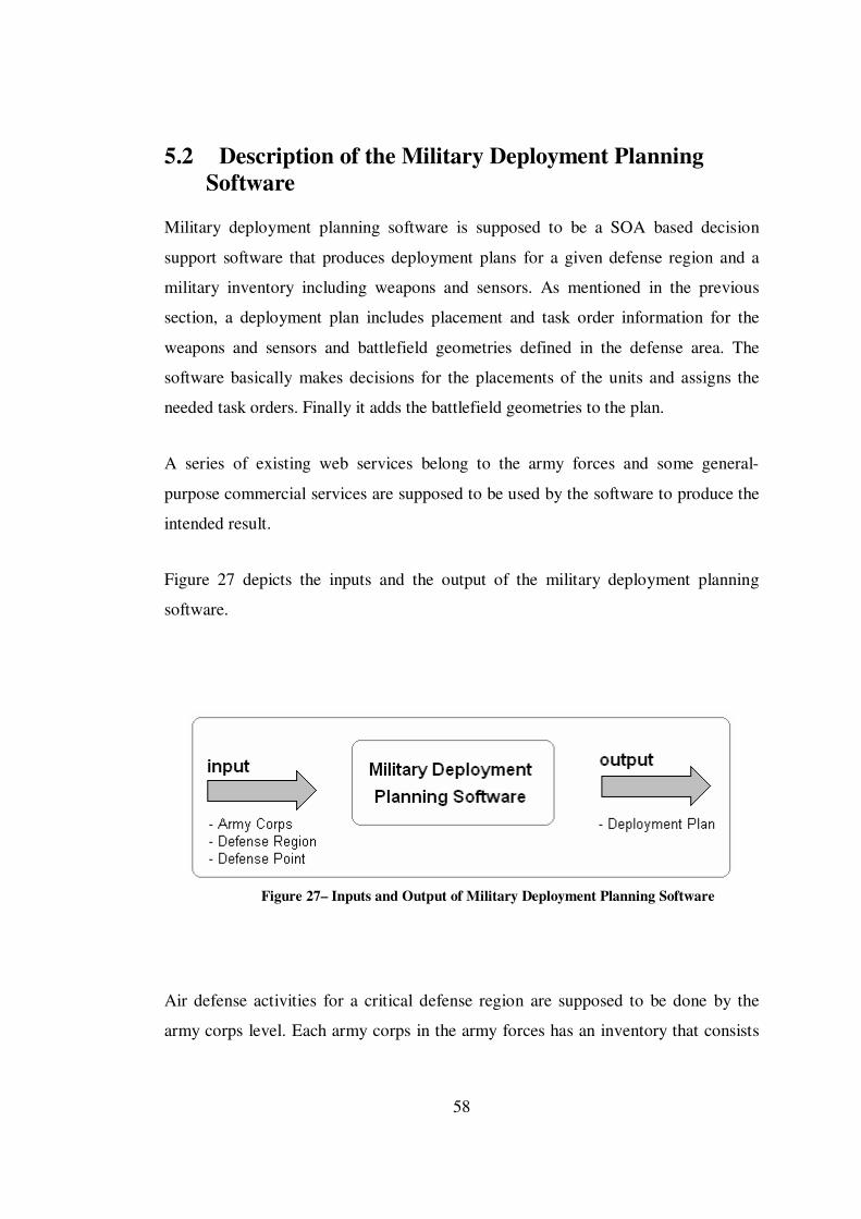
58
5.2 Description of the Military Deployment Planning Software
Military deployment planning software is supposed to be a SOA based decision
support software that produces deployment plans for a given defense region and a
military inventory including weapons and sensors. As mentioned in the previous
section, a deployment plan includes placement and task order information for the
weapons and sensors and battlefield geometries defined in the defense area. The
software basically makes decisions for the placements of the units and assigns the
needed task orders. Finally it adds the battlefield geometries to the plan.
A series of existing web services belong to the army forces and some general-
purpose commercial services are supposed to be used by the software to produce the
intended result.
Figure 27 depicts the inputs and the output of the military deployment planning
software.
Figure 27– Inputs and Output of Military Deployment Planning Software
Air defense activities for a critical defense region are supposed to be done by the
army corps level. Each army corps in the army forces has an inventory that consists
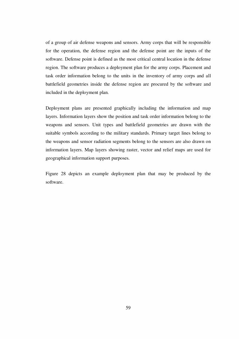
59
of a group of air defense weapons and sensors. Army corps that will be responsible
for the operation, the defense region and the defense point are the inputs of the
software. Defense point is defined as the most critical central location in the defense
region. The software produces a deployment plan for the army corps. Placement and
task order information belong to the units in the inventory of army corps and all
battlefield geometries inside the defense region are procured by the software and
included in the deployment plan.
Deployment plans are presented graphically including the information and map
layers. Information layers show the position and task order information belong to the
weapons and sensors. Unit types and battlefield geometries are drawn with the
suitable symbols according to the military standards. Primary target lines belong to
the weapons and sensor radiation segments belong to the sensors are also drawn on
information layers. Map layers showing raster, vector and relief maps are used for
geographical information support purposes.
Figure 28 depicts an example deployment plan that may be produced by the
software.
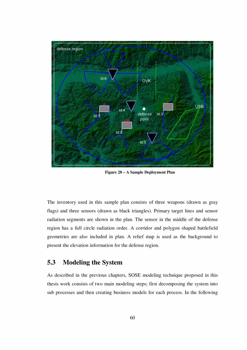
60
Figure 28 – A Sample Deployment Plan
The inventory used in this sample plan consists of three weapons (drawn as gray
flags) and three sensors (drawn as black triangles). Primary target lines and sensor
radiation segments are shown in the plan. The sensor in the middle of the defense
region has a full circle radiation order. A corridor and polygon shaped battlefield
geometries are also included in plan. A relief map is used as the background to
present the elevation information for the defense region.
5.3 Modeling the System
As described in the previous chapters, SOSE modeling technique proposed in this
thesis work consists of two main modeling steps; first decomposing the system into
sub processes and then creating business models for each process. In the following

61
sub sections, these steps are described in detail for the modeling of military
deployment planning software.
5.3.1 Decomposing the System into Sub Processes
Military deployment planning software simply has three inputs; army corps that will
perform the air defense operations, the defense region that will be defended and the
main defense point in this region. The output of the software is a deployment plan.
From SOSE modeling perspective, the software can be thought as a single and large
complex business process.
When the description and the requirements of the system are analyzed, the whole
system (process) can be decomposed into three main sub processes at the first level
of the decomposition. Figure 29 depicts the first level decomposition of the system.
Figure 29 – 1st Level Decomposition of the System
Military deployment planning process consists of three sub processes; deployment
decision support process, battlefield geometries supply process and plan presentation
process. Deployment decision support process basically includes the determination
of the inventory belong to the army corps, and decision making businesses for the
62
placements and task orders of the units. Battlefield geometries supply process is
responsible for obtaining the geometries belong to the air and land forces. Finally,
plan presentation process collects all plan data together and presents it on a GIS
panel.
After the first level decomposition, each sub process described above can be also
decomposed into relatively small sub processes.
Figure 30 depicts the second and the third level decompositions for the deployment
decision support process.
Figure 30 – 2nd and 3rd Level Decompositions for Deployment Decision Process
Deployment decision support process is decomposed into three different sub
processes at the second level and two of these sub processes are also decomposed
into other sub processes at the third level. Inventory procurance sub process procures
the inventory belong to the army corps. Unit deployment process consists of two sub

63
processes for weapons and sensors and it makes decisions for the placements of these
units inside the defense region. Finally task orders decision process assigns the task
orders of the units. It consists of two more sub processes; PTL (Primary Target Line)
decisions sub process for the weapons and SRS (Sensor Radiation Segments)
decisions sub process for the sensors.
Since the battlefield geometries supply process is a relatively simple and
straightforward process, it is not need to be decomposed into any other sub
processes. Finally plan presentation process can be still decomposed into two sub
processes more. Figure 31 depicts the second level decomposition for the plan
presentation process.
Figure 31 – 2nd Level Decomposition for Plan Presentation Process
Plan presentation process consists of two sub processes for presenting map and
information layers separately.
Figure 32 depicts the entire decomposition tree for the military deployment planning
system.
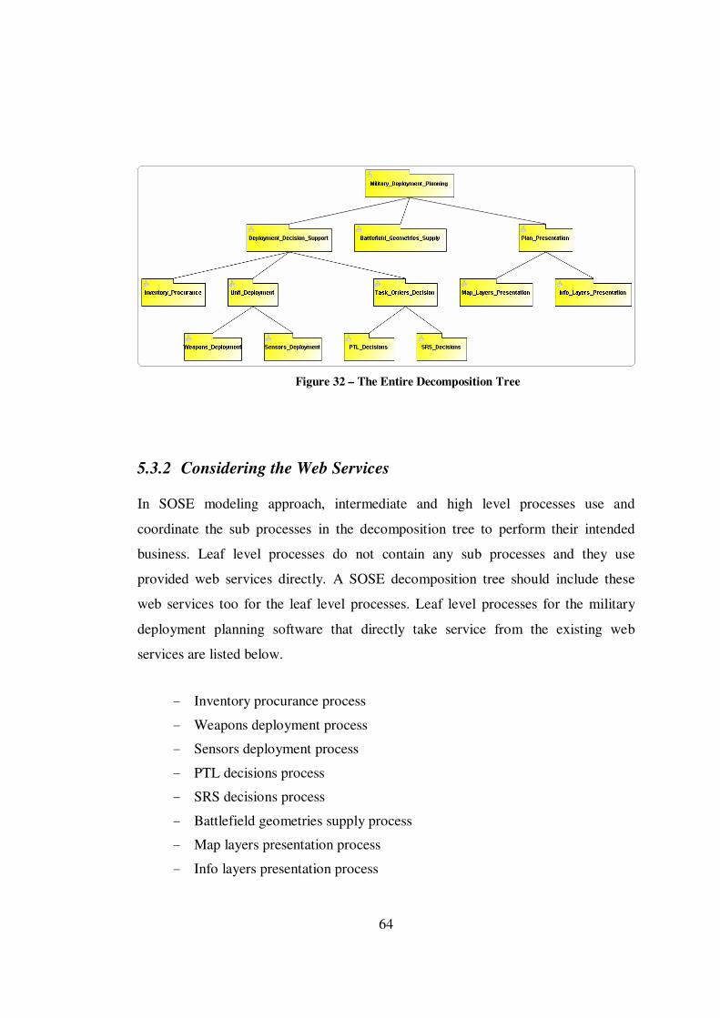
64
Figure 32 – The Entire Decomposition Tree
5.3.2 Considering the Web Services
In SOSE modeling approach, intermediate and high level processes use and
coordinate the sub processes in the decomposition tree to perform their intended
business. Leaf level processes do not contain any sub processes and they use
provided web services directly. A SOSE decomposition tree should include these
web services too for the leaf level processes. Leaf level processes for the military
deployment planning software that directly take service from the existing web
services are listed below.
- Inventory procurance process
- Weapons deployment process
- Sensors deployment process
- PTL decisions process
- SRS decisions process
- Battlefield geometries supply process
- Map layers presentation process
- Info layers presentation process
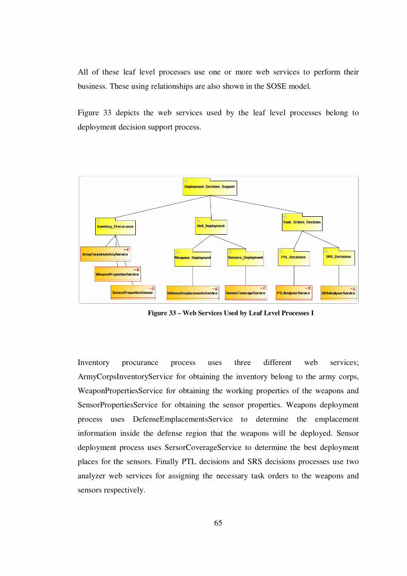
65
All of these leaf level processes use one or more web services to perform their
business. These using relationships are also shown in the SOSE model.
Figure 33 depicts the web services used by the leaf level processes belong to
deployment decision support process.
Figure 33 – Web Services Used by Leaf Level Processes I
Inventory procurance process uses three different web services;
ArmyCorpsInventoryService for obtaining the inventory belong to the army corps,
WeaponPropertiesService for obtaining the working properties of the weapons and
SensorPropertiesService for obtaining the sensor properties. Weapons deployment
process uses DefenseEmplacementsService to determine the emplacement
information inside the defense region that the weapons will be deployed. Sensor
deployment process uses SersorCoverageService to determine the best deployment
places for the sensors. Finally PTL decisions and SRS decisions processes use two
analyzer web services for assigning the necessary task orders to the weapons and
sensors respectively.

66
Figure 34 depicts the web services used by battlefield geometries supply process.
Figure 34 – Web Services Used by Leaf Level Processes II
Battlefield geometries supply process uses two web services; AirForcesBFGService
and LandForcesBFGService for obtaining the geometries for the air and land area
inside the defense region.
Figure 35 depicts the web services used by the leaf level processes belong to plan
presentation process.
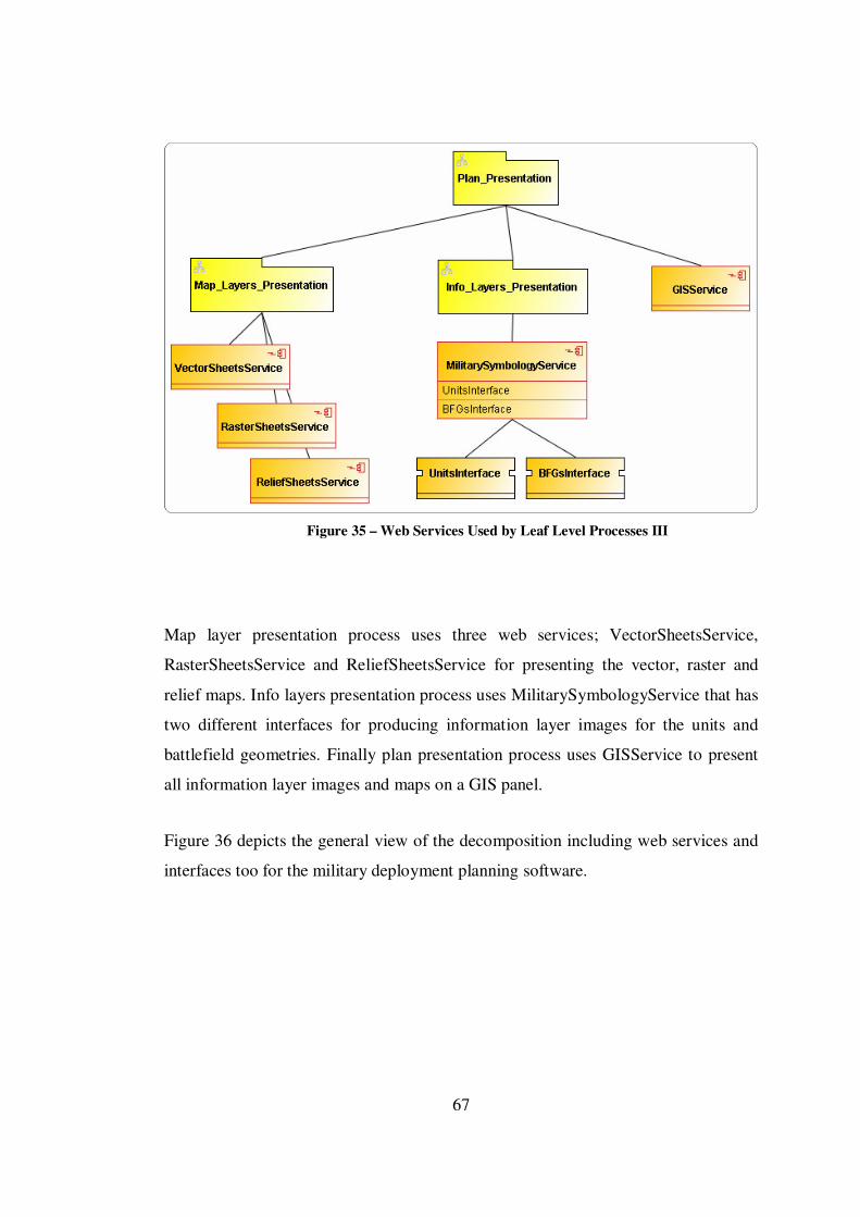
67
Figure 35 – Web Services Used by Leaf Level Processes III
Map layer presentation process uses three web services; VectorSheetsService,
RasterSheetsService and ReliefSheetsService for presenting the vector, raster and
relief maps. Info layers presentation process uses MilitarySymbologyService that has
two different interfaces for producing information layer images for the units and
battlefield geometries. Finally plan presentation process uses GISService to present
all information layer images and maps on a GIS panel.
Figure 36 depicts the general view of the decomposition including web services and
interfaces too for the military deployment planning software.

68
Figure 36 – The Entire Decomposition Tree with Web Services and Interfaces
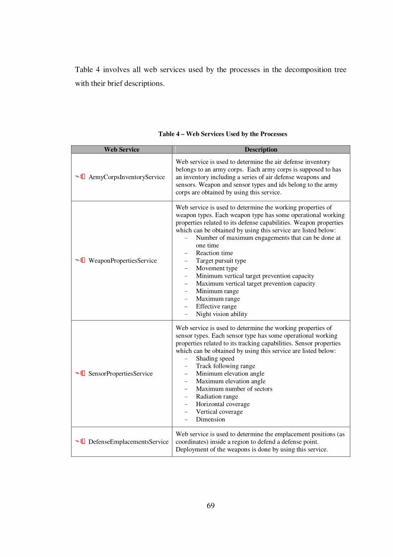
69
Table 4 involves all web services used by the processes in the decomposition tree
with their brief descriptions.
Table 4 – Web Services Used by the Processes
Web Service Description
ArmyCorpsInventoryService
Web service is used to determine the air defense inventory belongs to an army corps. Each army corps is supposed to has an inventory including a series of air defense weapons and sensors. Weapon and sensor types and ids belong to the army corps are obtained by using this service.
WeaponPropertiesService
Web service is used to determine the working properties of weapon types. Each weapon type has some operational working properties related to its defense capabilities. Weapon properties which can be obtained by using this service are listed below:
- Number of maximum engagements that can be done at one time
- Reaction time - Target pursuit type - Movement type - Minimum vertical target prevention capacity - Maximum vertical target prevention capacity - Minimum range - Maximum range - Effective range - Night vision ability
SensorPropertiesService
Web service is used to determine the working properties of sensor types. Each sensor type has some operational working properties related to its tracking capabilities. Sensor properties which can be obtained by using this service are listed below:
- Shading speed - Track following range - Minimum elevation angle - Maximum elevation angle - Maximum number of sectors - Radiation range - Horizontal coverage - Vertical coverage - Dimension
DefenseEmplacementsService Web service is used to determine the emplacement positions (as coordinates) inside a region to defend a defense point. Deployment of the weapons is done by using this service.
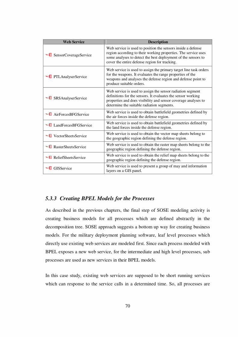
70
Web Service Description
SensorCoverageService
Web service is used to position the sensors inside a defense region according to their working properties. The service uses some analyses to detect the best deployment of the sensors to cover the entire defense region for tracking.
PTLAnalyserService
Web service is used to assign the primary target line task orders for the weapons. It evaluates the range properties of the weapons and analyses the defense region and defense point to produce suitable orders.
SRSAnalyserService
Web service is used to assign the sensor radiation segment definitions for the sensors. It evaluates the sensor working properties and does visibility and sensor coverage analyses to determine the suitable radiation segments.
AirForcesBFGService Web service is used to obtain battlefield geometries defined by the air forces inside the defense region.
LandForcesBFGService Web service is used to obtain battlefield geometries defined by the land forces inside the defense region.
VectorSheetsService Web service is used to obtain the vector map sheets belong to the geographic region defining the defense region.
RasterSheetsService Web service is used to obtain the raster map sheets belong to the geographic region defining the defense region.
ReliefSheetsService Web service is used to obtain the relief map sheets belong to the geographic region defining the defense region.
GISService Web service is used to present a group of may and information layers on a GIS panel.
5.3.3 Creating BPEL Models for the Processes
As described in the previous chapters, the final step of SOSE modeling activity is
creating business models for all processes which are defined abstractly in the
decomposition tree. SOSE approach suggests a bottom up way for creating business
models. For the military deployment planning software, leaf level processes which
directly use existing web services are modeled first. Since each process modeled with
BPEL exposes a new web service, for the intermediate and high level processes, sub
processes are used as new services in their BPEL models.
In this case study, existing web services are supposed to be short running services
which can response to the service calls in a determined time. So, all processes are
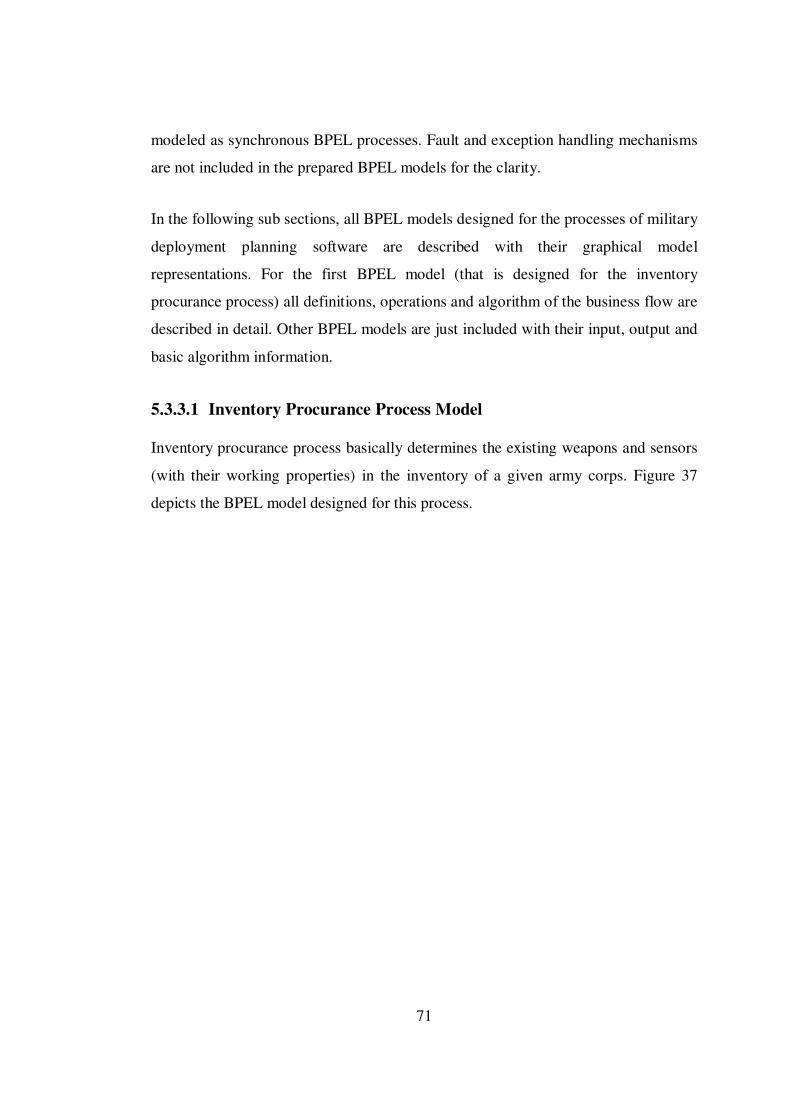
71
modeled as synchronous BPEL processes. Fault and exception handling mechanisms
are not included in the prepared BPEL models for the clarity.
In the following sub sections, all BPEL models designed for the processes of military
deployment planning software are described with their graphical model
representations. For the first BPEL model (that is designed for the inventory
procurance process) all definitions, operations and algorithm of the business flow are
described in detail. Other BPEL models are just included with their input, output and
basic algorithm information.
5.3.3.1 Inventory Procurance Process Model
Inventory procurance process basically determines the existing weapons and sensors
(with their working properties) in the inventory of a given army corps. Figure 37
depicts the BPEL model designed for this process.
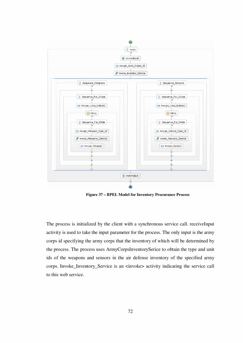
72
Figure 37 – BPEL Model for Inventory Procurance Process
The process is initialized by the client with a synchronous service call. receiveInput
activity is used to take the input parameter for the process. The only input is the army
corps id specifying the army corps that the inventory of which will be determined by
the process. The process uses ArmyCorpsInventorySerice to obtain the type and unit
ids of the weapons and sensors in the air defense inventory of the specified army
corps. Invoke_Inventory_Service is an <invoke> activity indicating the service call
to this web service.

73
Web service method invocations are done with operation request and response
messages. Request messages are sent to the services as input parameters and
response messages are returned from the services as the outputs of the operation.
Each request and response message contains variables with simple or complex types.
All of these operation, message and type definitions are included in the WSDL files
of web services. Each web service is added to a BPEL model as a partner link with
its WSDL file. Assign_Army_Corps_Id is an <assign> activity and basically copies
the army corps id (which is taken as the input parameter of the process) to the
variable in the request message for the inventory web service call.
After the Invoke_Inventory_Service activity, the result of the service call (weapon
and sensor ids) is obtained as a variable in the request message taken from the
service. This variable is a complex type variable which is in fact an array containing
the weapon and sensor ids.
After the first service call, a <flow> activity is used to define two separate branches
which should be executed in parallel. In one of these two branches, weapon working
properties are obtained one by one by using WeaponPropertiesService and in the
second branch sensor properties are obtained by using SensorPropertiesService.
Since two different web services are used for weapons and sensors, there is no
problem with executing these two branches in parallel.
In each branch, <while> activities are used to construct loops in separate scopes
which are defined with <scope> activities in the model. Assign_Loop_Indexes
activities simply prepare the loop variables and indexes before the loop operations. In
each loop, weapon and sensor ids obtained from the first service call are sent to the
properties services one by one. After the each service call, the properties returned in
the response messages are copied to the output message of the main process by using
<assign> activities.
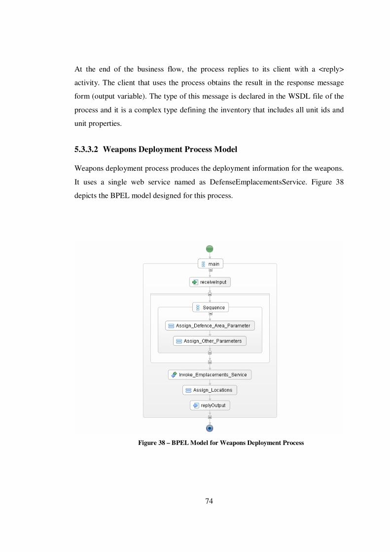
74
At the end of the business flow, the process replies to its client with a <reply>
activity. The client that uses the process obtains the result in the response message
form (output variable). The type of this message is declared in the WSDL file of the
process and it is a complex type defining the inventory that includes all unit ids and
unit properties.
5.3.3.2 Weapons Deployment Process Model
Weapons deployment process produces the deployment information for the weapons.
It uses a single web service named as DefenseEmplacementsService. Figure 38
depicts the BPEL model designed for this process.
Figure 38 – BPEL Model for Weapons Deployment Process
75
Input/Output: Defense region and the defense point that will be defended in this
region are the inputs of the process. The output of the process is an array of
coordinates that the weapons will be deployed.
Algorithm: The process prepares the defense area, defense point and emplacement
count parameters before the service invocation with two <assign> activities. Then the
service is invoked and locations returned from the service call are assigned to the
output parameter.
5.3.3.3 Sensors Deployment Process Model
Sensors deployment process produces the deployment information for the sensors. It
uses a single web service named as SersorCoverageService. Figure 39 depicts the
BPEL model designed for this process.

76
Figure 39 – BPEL Model for Sensors Deployment Process
Input/Output: The scope that will be covered by the sensors and an array containing
the working properties of all sensors are the inputs. The output of the process is an
array of coordinates that the sensors will be deployed.
Algorithm: The process prepares the scope parameter with the first <assign>
activity. Sensor properties parameter is also prepared inside a loop for each sensor.
Then the service is invoked and locations returned from the service call are assigned
to the output parameter.
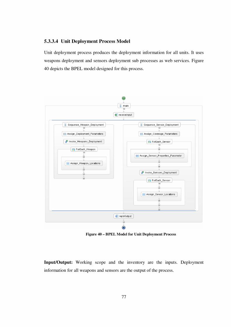
77
5.3.3.4 Unit Deployment Process Model
Unit deployment process produces the deployment information for all units. It uses
weapons deployment and sensors deployment sub processes as web services. Figure
40 depicts the BPEL model designed for this process.
Figure 40 – BPEL Model for Unit Deployment Process
Input/Output: Working scope and the inventory are the inputs. Deployment
information for all weapons and sensors are the output of the process.
78
Algorithm: The process produces weapons and sensors deployment information in
parallel by using two branches. Input parameters for weapons and sensors
deployment sub processes are prepared before the invocations. Then the sub
processes are invoked and locations returned from the service calls are assigned to
the output parameter at the end of two branches.
5.3.3.5 PTL Decisions Process Model
PTL decisions process produces PTL task orders for the weapons. It uses a single
web service named as PTLAnalyserService . Figure 41 depicts the BPEL model
designed for this process.
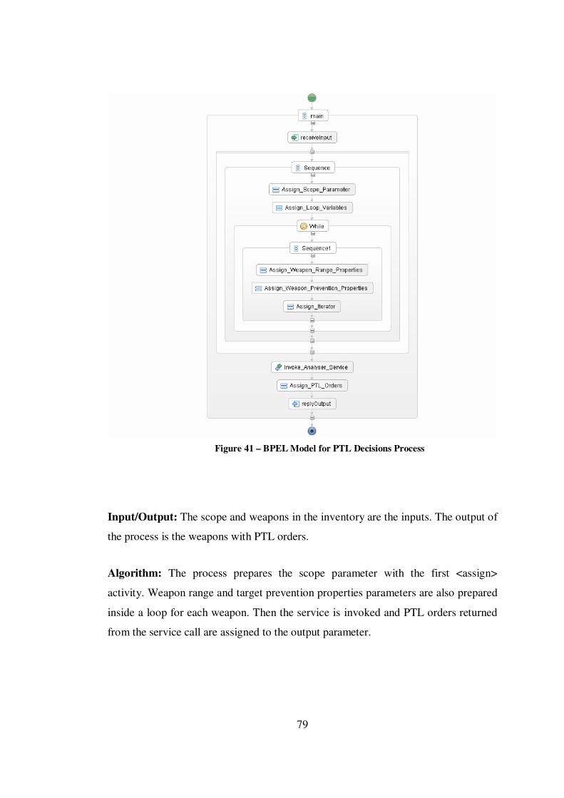
79
Figure 41 – BPEL Model for PTL Decisions Process
Input/Output: The scope and weapons in the inventory are the inputs. The output of
the process is the weapons with PTL orders.
Algorithm: The process prepares the scope parameter with the first <assign>
activity. Weapon range and target prevention properties parameters are also prepared
inside a loop for each weapon. Then the service is invoked and PTL orders returned
from the service call are assigned to the output parameter.
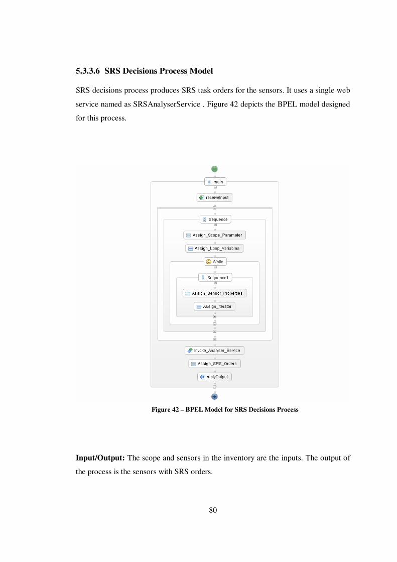
80
5.3.3.6 SRS Decisions Process Model
SRS decisions process produces SRS task orders for the sensors. It uses a single web
service named as SRSAnalyserService . Figure 42 depicts the BPEL model designed
for this process.
Figure 42 – BPEL Model for SRS Decisions Process
Input/Output: The scope and sensors in the inventory are the inputs. The output of
the process is the sensors with SRS orders.

81
Algorithm: The process prepares the scope parameter with the first <assign>
activity. Sensor properties parameter is also prepared inside a loop for each sensor.
Then the service is invoked and SRS orders returned from the service call are
assigned to the output parameter.
5.3.3.7 Task Orders Decision Process Model
Task orders decision process produces the PTL orders for the weapons and SRS
orders for the sensors. It uses PTL decisions and SRS decisions sub processes as web
services. Figure 43 depicts the BPEL model designed for this process.
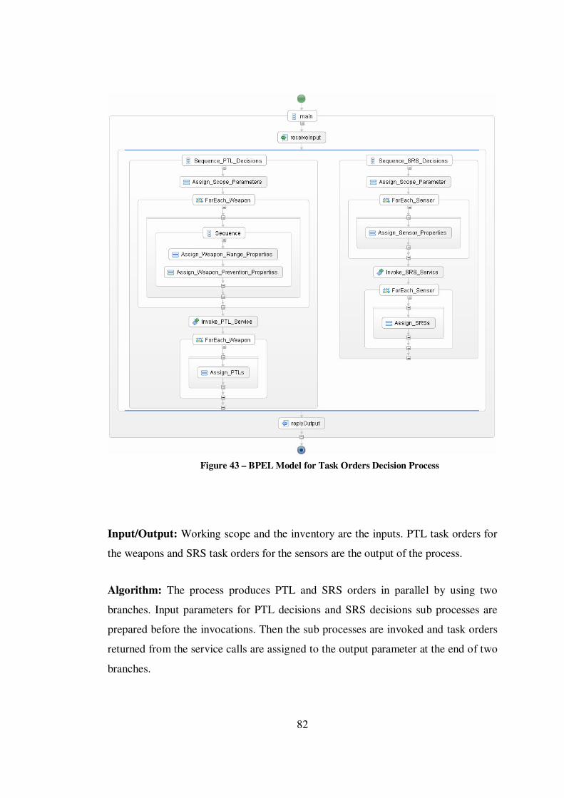
82
Figure 43 – BPEL Model for Task Orders Decision Process
Input/Output: Working scope and the inventory are the inputs. PTL task orders for
the weapons and SRS task orders for the sensors are the output of the process.
Algorithm: The process produces PTL and SRS orders in parallel by using two
branches. Input parameters for PTL decisions and SRS decisions sub processes are
prepared before the invocations. Then the sub processes are invoked and task orders
returned from the service calls are assigned to the output parameter at the end of two
branches.

83
5.3.3.8 Deployment Decision Support Process Model
Deployment decisions support process obtains the inventory and makes decisions for
the placements and task orders of the units. It uses inventory procurance, unit
deployment and task orders decisions sub processes as web services. Figure 44
depicts the BPEL model designed for this process.
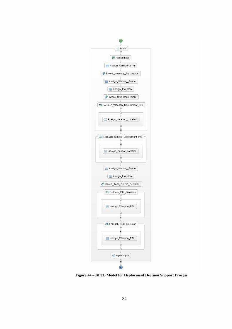
84
Figure 44 – BPEL Model for Deployment Decision Support Process
85
Input/Output: Working scope and the army corps id are the inputs. The inventory
including all weapons and sensors with the placements and task orders information is
the output of the process.
Algorithm: The process uses its three sub processes sequentially. It first invokes the
inventory procurance process (or web service) to obtain the inventory belong the
specified army corps. Then it uses unit deployment sub process to get the placement
information for the units. Finally task orders decision sub process is invoked for
assigning the necessary task orders. Between these three service calls, essential
variable assignment operations are done by using <assign> activities.
5.3.3.9 Battlefield Geometries Supply Process Model
Battlefield geometries supply process obtains the battlefield geometries inside the
defense region. It uses two different web services for the air and land forces
geometries named as AirForcesBFGService and LandForcesBFGService
respectively. Figure 45 depicts the BPEL model designed for this process.
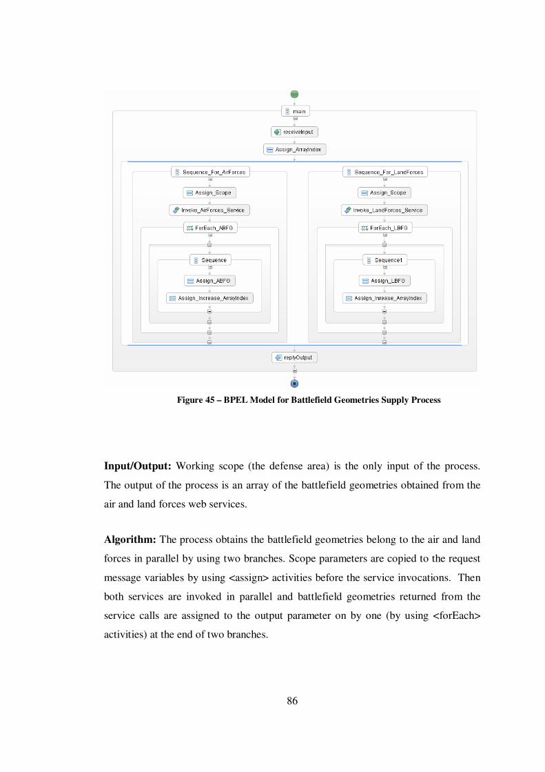
86
Figure 45 – BPEL Model for Battlefield Geometries Supply Process
Input/Output: Working scope (the defense area) is the only input of the process.
The output of the process is an array of the battlefield geometries obtained from the
air and land forces web services.
Algorithm: The process obtains the battlefield geometries belong to the air and land
forces in parallel by using two branches. Scope parameters are copied to the request
message variables by using <assign> activities before the service invocations. Then
both services are invoked in parallel and battlefield geometries returned from the
service calls are assigned to the output parameter on by one (by using <forEach>
activities) at the end of two branches.
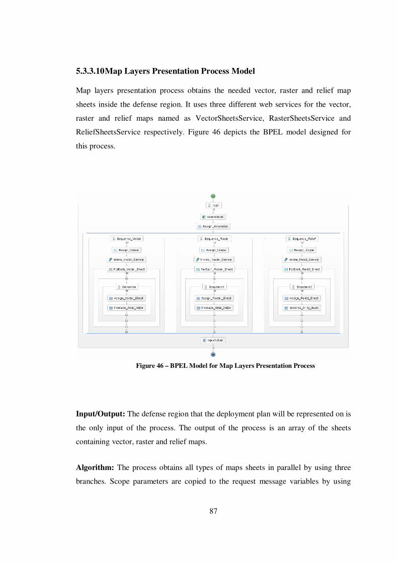
87
5.3.3.10 Map Layers Presentation Process Model
Map layers presentation process obtains the needed vector, raster and relief map
sheets inside the defense region. It uses three different web services for the vector,
raster and relief maps named as VectorSheetsService, RasterSheetsService and
ReliefSheetsService respectively. Figure 46 depicts the BPEL model designed for
this process.
Figure 46 – BPEL Model for Map Layers Presentation Process
Input/Output: The defense region that the deployment plan will be represented on is
the only input of the process. The output of the process is an array of the sheets
containing vector, raster and relief maps.
Algorithm: The process obtains all types of maps sheets in parallel by using three
branches. Scope parameters are copied to the request message variables by using

88
<assign> activities before the service invocations. Then the services are invoked in
parallel and map sheets returned from the service calls are assigned to the output
parameter on by one (by using <forEach> activities) at the end of three branches.
5.3.3.11 Info Layers Presentation Process Model
Info layers presentation process produces the images including the military symbols
of the units and battlefield geometries belong to the deployment plan. It uses a single
web service named as MilitarySymbologyService that has two service interfaces for
the units and battlefield geometries respectively. Figure 47 depicts the BPEL model
designed for this process.
Figure 47 – BPEL Model for Info Layers Presentation Process
89
Input/Output: Inventory, placement and task order information and battlefield
geometries are the inputs of the process. The output of the process is an array of
images showing the units and the geometries according to the military symbology.
Algorithm: The process obtains the images showing the units and the battlefield
geometries sequentially. Weapons, sensors and battlefield geometries are copied to
the request message variables by using <assign> activities before the service
invocations. Images returned from the service calls are assigned to the output
parameter.
5.3.3.12 Plan Presentation Process Model
Plan presentation process combines all the map sheets and info layer images together
and presents the deployment plan on a GIS panel graphically. It uses map layers
presentation and info layers presentation sub processes to produce the necessary
layers and GISService (a web service) to finally present the deployment plan. Figure
48 depicts the BPEL model designed for this process.

90
Figure 48 – BPEL Model for Plan Presentation Process
Input/Output: The working scope, inventory and battlefield geometries are the
inputs of the process. The output of the process is a GIS panel representing the plan.
Algorithm: The process obtains the info layer images and map sheets from its two
sub processes in parallel. Map sheets and info layer images are then copied to the
request message variables of GISService by using <assign> activities. Finally the
GIS panel returned from the last web service call is assigned to the output parameter.
5.3.3.13 Military Deployment Planning Process Model
Military deployment planning process produces the complete deployment plan for
the air defense operations as the root process of the decomposition tree. It uses
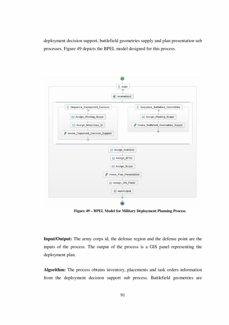
91
deployment decision support, battlefield geometries supply and plan presentation sub
processes. Figure 49 depicts the BPEL model designed for this process.
Figure 49 – BPEL Model for Military Deployment Planning Process
Input/Output: The army corps id, the defense region and the defense point are the
inputs of the process. The output of the process is a GIS panel representing the
deployment plan.
Algorithm: The process obtains inventory, placements and task orders information
from the deployment decision support sub process. Battlefield geometries are

92
obtained from the battlefield geometries supply sub process. These two processes are
executed in parallel. Finally all data is collected together and plan presentation sub
process is used to present the deployment plan on a GIS panel.
93
CHAPTER 6
6. CONCLUSION AND FUTURE WORK
In this thesis study, a service oriented system design approach is introduced for
realizing SOA based software development. The idea behind the purposed
methodology is basically a functional decomposition of the system in several
abstraction levels. The whole software system is accepted as a single and complex
business process which can be decomposed into smaller sub processes. The first step
of the modeling activity is decomposing the system into high level processes which
in fact contain and define other sub processes. Processes are decomposed iteratively
in a top down manner until more real and concrete processes are reached at the leaf
level of the decomposition tree. Finally, web services that will be used by the leaf
level processes are specified to achieve the process goals.
After the construction of the process decomposition tree for the target software,
processes at each level are modeled with a standard business process definition
language. To create the detailed process models which describe the whole process
flow in an algorithmic way, BPEL (Business Process Execution Language) is used.
The BPEL models for the leaf level processes in the decomposition tree define the
interactions between the processes and existing web services. For the intermediate
and higher level processes, sub processes are supposed as newly exposed web
services and interactions between different processes are defined. Thus, the entire
software system is modeled with its all details.
The modeling technique introduced in this thesis is also supported with a modeling
language referred to as SOSEML (Service Oriented Software Engineering Modeling
Language). A supporting tool, SOSECASE is also developed, waiting to be used in
the validation of the approach. The tool is integrated with an open source BPEL

94
designer interface and it allows the system designers to create SOSE models
including the exact BPEL process models.
During this thesis study, an interesting observation was the emphasis in different
approaches, usually manifesting itself as the main concern in the decomposition of a
system. Function had been the design dimension that was important in the earliest
approaches that yielded to data with the establishment of Object Orientation. Later,
Components moved this emphasis to the structure dimension. Looks like the
approach is back to the functional paradigm, actually to be more specific, the
procedural dimension is the main concern in SOSEML. Highest-level entity is a
process that decomposes into further processes, arriving at web services that could
also be regarded as processes.
Activities done in the different steps of software development processes benefit the
quality of the final business product in various levels. Although analysis, design,
implementation and test phases do not change much for several development
processes, it is known that different approaches, methods and techniques used in the
practice directly affect the quality.
In this thesis study, a design approach with the concept of service oriented software
development processes is proposed. Various historical and experimental facts related
to design paradigms are considered and different approaches used in different
methodologies are evaluated. Finally, it is claimed that SOSE modeling approach is
theoretically acceptable and usable according to the obtained throughputs. To
observe the possible benefits or difficulties of the approach in practice, a well
defined real software system is modeled step by step as offered in this thesis. For this
case study, a comprehensive and detailed sample software system is chosen to get the
more realistic results.
During the case study, it is observed that accepting the whole system as a single
process at the first step, decomposing it into sub processes and constructing a

95
decomposition tree is a good starting point for modeling a large software system. In
this way, indistinctness and ambiguity at the beginning of the design could be
decreased gradually and the foundations of the design could be produced easier.
After specifying the all processes and constructing a hierarchical decomposition tree,
it is proposed to create business models for all processes in an algorithmic way. At
this point a bottom up fashion is recommended. After creating business models for
the leaf level processes and specifying the inputs and outputs of each leaf level
process, it is observed that modeling the intermediate and high level processes can be
done easier.
A completed SOSE model includes the whole design details of the system at
algorithmic level. Today, BPEL is a process modeling language that is widely used
in industry and the benefits of modeling business processes with BPEL is accepted
after commercial usages. SOSE modeling technique also proposes the usage of
BPEL and this will facilitate the usage of SOSEML in industry in the future.
The basic philosophy of the service oriented software development is based on the
services that will be provided and requested. In other words, the emphasis is on
services and function is the key word. As suitable to this, in SOSE modeling
technique, process decomposition approach strengthens the link between the design
and realization. From this perspective, it is observed that SOSE technique is suitable
to service oriented architecture.
It is not so realistic to claim that any modeling approach is completely successful or
completely inapplicable. But all evaluations, determinations and the case study done
in the scope of this thesis study point out that SOSE modeling approach will produce
successful results during service oriented software development processes. With the
development of new opportunities to put this approach to test, it is hoped to report
success stories.
96
More experiments and tests on SOSE modeling technique are needed in different
domains. In the scope of this thesis study, a sample software system was modeled
with SOSEML, but its implementation was not included. An implementation of a
modeled system with SOSEML may be very useful to observe the benefits and the
effects of the purposed design technique.
As future work, a new BPEL designer specific to the SOSEML can be developed
instead of using an open source designer and a new SOSEML specific business
process definition language can be defined and used for modeling the processes in a
SOSE decomposition tree.
97
REFERENCES
[1] Herbert Alexander Simon, “The Science of the Artificial”, 3rd Ed., the MIT Press, 1996. [2] Murray Cantor, “The Role of Logical Decomposition in System Architecture”, http://www.ibm.com/developerworks/rational/library/aug07/cantor, last accessed 6/23/2008. [3] Ali Hikmet Dogru, Murat M. Tanik, “A Process Model for Component-Oriented Software Engineering”, IEEE Software, IEEE Computer Society, Vol. 20, No. 2, pp. 34-41, April 2003. [4] Kimberly Jordan, “Software Reuse Term Paper for the MJY Team Software Risk Management www Site”, http://www.baz.com/kjordan/swse625/htm/tp-kj.htm, last accessed 5/8/2008. [5] Ayesha Manzer, Ali Hikmet Dogru, “Process Integration through Hierarchical Decomposition”, in Enterprise Architecture and Integration: Methods, Implementation and Technologies, Information Science Reference, New York, 2007. [6] K. Gottschalk, S. Graham, H. Kreger, J. Snell, “Introduction to Web Services Architecture”, Gottschalk Et. Al., IBM System Journal, Vol. 41, No. 2, 2002. [7] Matjaz B. Juric, Benny Mathew, Poornachandra Sarang, “Business Process Execution Language for Web Services”, 2nd Ed., Packt Publishing, Birmingham, January 2006. [8] Ali Arsanjani, Bernhard Borges, Kerrie Holley, “Service-Oriented Architecture: Components and Modeling Can Make the Difference (SOA vs. CBA)”, Web Services Journal, September 2004.

98
[9] Frank Buschmann, Regine Meunier, Hans Rohnert, Peter Sommerlad, Michael Stal, “Pattern Oriented Software Architecture”, 1st Ed., John Wiley & Sons, August 1996. [10] Mike P. Papazoglou, Dimitrios Georgakopoulos, “Service-Oriented Computing”, Communications of the ACM, Vol. 46, No. 10, pp. 24-28, October 2003. [11] Harry M. Sneed, “Integrating Legacy Software into a Service Oriented Architecture”, Proceedings of the Conference on Software Maintenance and Reengineering, IEEE Computer Society, pp. 3-14, 2006. [12] Software Technologies Unit Information Society and Media DG European Commission, “Software, Services and Complexity Research in the IST Programme”, 2006. [13] W3C, Web Services Architecture Working Group Note, http://www.w3.org/TR/ws-arch, last accesses 7/10/2008. [14] Bill Curtis, Marc I. Kellner, Jim Over, “Process Modeling”, Communications of the ACM, Vol. 35, No. 9, pp. 75-90, September 1992. [15] O. Tufekci, S. Cetin, I. Altintas, “How to Process [Business] Processes”, The 9th World Conference on Integrated Design and Process Technology, San Diego, California, 2006. [16] Eren Kocak Akbiyik, Selma Suloglu, Cengiz Togay, Ali Hikmet Dogru, “Service Oriented System Design Through Process Decomposition”, Integrated Design and Process Technology 2008, Taiwan, June 2008. [17] Dirk Beyer, Arindam Chakrabarti, Thomas A. Henzinger, “Web Service Interfaces”, Proceedings of the 14th International Conference on World Wide Web, ACM, pp. 148-159, 2005.

99
[18] Jeffrey Gortmaker, Marijn Janssen, Rene W. Wagenaar, “The Advantages of Web Service Orchestration in Perspective”, Proceedings of the 6th International Conference on Electronic Commerce, ACM, Vol. 60, pp. 506-515, 2004.