Embed Size (px)
Citation preview
Service Oriented Architecturefor Embedded (Avionics)
Applications
JUAN LÓPEZ RUBIOComputer Science Engineer
AdvisorsDR. ENRIC PASTOR LLORENS
DR. CRISTINA BARRADO MUXI
The PhD Program on Computer Architecture
Technical School of CastelldefelsTechnical University of Catalonia
Programa de doctorat en Arquitectura de Computadors
Escola Politécnica Superior de Castelldefels (EPSC)Universitat Politécnica de Catalunya (UPC)
A dissertation submitted for the degree ofEuropean Doctor of Philosophy
January 2011

Service Oriented Architecture for Embedded (Avionics) Applications
The PhD Program on Computer ArchitectureTechnical University of CataloniaJanuary 2011
This dissertation is available on-line at the Theses and Dissertations On-line (TDX) repository, which is man-aged by the Consortium of University Libraries of Catalonia (CBUC) and the Supercomputing Centre ofCatalonia (CESCA), and sponsored by the Generalitat (government) of Catalonia. The TDX repository isa member of the Networked Digital Library of Theses and Dissertations (NDLTD) which is an interna-tional organisation dedicated to promoting the adoption, creation, use, dissemination and preservationof electronic analogues to the traditional paper-based theses and dissertationshttp://www.tesisenxarxa.net
PhD thesis written at:Technical School of CastelldefelsEsteve Terradas, 708860 CastelldefelsCatalonia (Spain)
This work is licensed under the Creative Commons Attribution-Non-commercial-
No Derivative Work 3.0 Spain License. To view a copy of this license, visit http://
creativecommons.org/licenses/by-nc-nd/3.0/es/deed.en_GB or send
a letter to Creative Commons, 171 Second Street, Suite 300, San Francisco, Califor-
nia, 94105, USA.

A Carol

Contents
List of Figures . . . . . . . . . . . . . . . . . . . . . . . . . . . . . . . . . . . . . ix
List of Tables . . . . . . . . . . . . . . . . . . . . . . . . . . . . . . . . . . . . . xiii
List of Publications . . . . . . . . . . . . . . . . . . . . . . . . . . . . . . . . . . xv
Agradecimientos . . . . . . . . . . . . . . . . . . . . . . . . . . . . . . . . . . . xix
Abstract . . . . . . . . . . . . . . . . . . . . . . . . . . . . . . . . . . . . . . . . xxi
CHAPTER I Introduction . . . . . . . . . . . . . . . . . . . . . . . . . . . . . . 1I.1 Thesis overview . . . . . . . . . . . . . . . . . . . . . . . . . . . . . . . . 1
I.2 Unmanned Aerial Vehicles . . . . . . . . . . . . . . . . . . . . . . . . . . 2
I.3 Motivation . . . . . . . . . . . . . . . . . . . . . . . . . . . . . . . . . . . 2
I.4 Thesis objectives . . . . . . . . . . . . . . . . . . . . . . . . . . . . . . . 6
I.5 Thesis outline . . . . . . . . . . . . . . . . . . . . . . . . . . . . . . . . . 7
CHAPTER II Previous work . . . . . . . . . . . . . . . . . . . . . . . . . . . . . 9II.1 Introduction . . . . . . . . . . . . . . . . . . . . . . . . . . . . . . . . . . 9
II.2 CORBA . . . . . . . . . . . . . . . . . . . . . . . . . . . . . . . . . . . . 10
II.3 Avionics . . . . . . . . . . . . . . . . . . . . . . . . . . . . . . . . . . . . 17
II.4 Joint Arquitecture for Unmanned Systems (JAUS) / SAE AS-4 . . . . . 22
II.5 STANAG 4586 . . . . . . . . . . . . . . . . . . . . . . . . . . . . . . . . . 24
II.6 Robotic middleware . . . . . . . . . . . . . . . . . . . . . . . . . . . . . . 25
II.7 Conclusions . . . . . . . . . . . . . . . . . . . . . . . . . . . . . . . . . . 29
v
CHAPTER III System Requirements . . . . . . . . . . . . . . . . . . . . . . . . 31III.1 Civil Missions for Unmanned Aircraft Vehicles . . . . . . . . . . . . . . 31
III.2 Non-Functional Requirements . . . . . . . . . . . . . . . . . . . . . . . 33
III.3 Functional Requirements . . . . . . . . . . . . . . . . . . . . . . . . . . 37
III.4 Conclusions . . . . . . . . . . . . . . . . . . . . . . . . . . . . . . . . . . 40
CHAPTER IV Service-Oriented Architecture . . . . . . . . . . . . . . . . . . . 41IV.1 Introduction . . . . . . . . . . . . . . . . . . . . . . . . . . . . . . . . . . 41
IV.2 Service definition . . . . . . . . . . . . . . . . . . . . . . . . . . . . . . . 43
IV.3 Communication primitives . . . . . . . . . . . . . . . . . . . . . . . . . . 45
IV.4 Naming . . . . . . . . . . . . . . . . . . . . . . . . . . . . . . . . . . . . 50
IV.5 Service Description . . . . . . . . . . . . . . . . . . . . . . . . . . . . . . 54
IV.6 Integration of Marea in UAV avionics . . . . . . . . . . . . . . . . . . . . 55
IV.7 Conclusions . . . . . . . . . . . . . . . . . . . . . . . . . . . . . . . . . . 57
CHAPTER V Marea Design and Implementation . . . . . . . . . . . . . . . . 59V.1 Introduction . . . . . . . . . . . . . . . . . . . . . . . . . . . . . . . . . . 59
V.2 Layers . . . . . . . . . . . . . . . . . . . . . . . . . . . . . . . . . . . . . 63
V.3 Service Management . . . . . . . . . . . . . . . . . . . . . . . . . . . . . 67
V.4 Name Management . . . . . . . . . . . . . . . . . . . . . . . . . . . . . 69
V.5 Network Abstraction and Management . . . . . . . . . . . . . . . . . . . 73
V.6 Resource Management . . . . . . . . . . . . . . . . . . . . . . . . . . . 86
V.7 Example. Multiple battery management system. . . . . . . . . . . . . . 90
V.8 Conclusions . . . . . . . . . . . . . . . . . . . . . . . . . . . . . . . . . . 97
CHAPTER VI Startup mechanisms . . . . . . . . . . . . . . . . . . . . . . . . . 99VI.1 Introduction . . . . . . . . . . . . . . . . . . . . . . . . . . . . . . . . . . 99
VI.2 Dispatching . . . . . . . . . . . . . . . . . . . . . . . . . . . . . . . . . . 100
VI.3 Startup . . . . . . . . . . . . . . . . . . . . . . . . . . . . . . . . . . . . . 104
VI.4 Marea Control Console . . . . . . . . . . . . . . . . . . . . . . . . . . . 111
VI.5 Conclusions . . . . . . . . . . . . . . . . . . . . . . . . . . . . . . . . . . 116
CHAPTER VII Communication Gateway . . . . . . . . . . . . . . . . . . . . . . 119VII.1 Introduction . . . . . . . . . . . . . . . . . . . . . . . . . . . . . . . . . . 119
VII.2 System Requirements . . . . . . . . . . . . . . . . . . . . . . . . . . . . 123
vi
VII.3 System architecture . . . . . . . . . . . . . . . . . . . . . . . . . . . . . 124
VII.4 Configuration . . . . . . . . . . . . . . . . . . . . . . . . . . . . . . . . . 133
VII.5 Conclusions . . . . . . . . . . . . . . . . . . . . . . . . . . . . . . . . . . 135
CHAPTER VIII Performance evaluation . . . . . . . . . . . . . . . . . . . . . . . 137VIII.1 Introduction . . . . . . . . . . . . . . . . . . . . . . . . . . . . . . . . . . 137
VIII.2 Testing environment . . . . . . . . . . . . . . . . . . . . . . . . . . . . . 138
VIII.3 Marea traffic characterization . . . . . . . . . . . . . . . . . . . . . . . . 140
VIII.4 Unit testing . . . . . . . . . . . . . . . . . . . . . . . . . . . . . . . . . . . 143
VIII.5 Comparison with other systems . . . . . . . . . . . . . . . . . . . . . . . 146
VIII.6 Conclusions . . . . . . . . . . . . . . . . . . . . . . . . . . . . . . . . . . 153
CHAPTER IX Application examples . . . . . . . . . . . . . . . . . . . . . . . . 155IX.1 Introduction . . . . . . . . . . . . . . . . . . . . . . . . . . . . . . . . . . 155
IX.2 Icarus Simulation Integrated Scenario . . . . . . . . . . . . . . . . . . . 156
IX.3 RedEye . . . . . . . . . . . . . . . . . . . . . . . . . . . . . . . . . . . . 173
CHAPTER X Conclusions . . . . . . . . . . . . . . . . . . . . . . . . . . . . . . 193X.1 Summary of contributions . . . . . . . . . . . . . . . . . . . . . . . . . . 193
X.2 Future work . . . . . . . . . . . . . . . . . . . . . . . . . . . . . . . . . . 196
References . . . . . . . . . . . . . . . . . . . . . . . . . . . . . . . . . . . . . . . . 199
vii

List of Figures
I-1 Classical and smart-sensor architecture for an aircraft fuel gauge sys-tem. . . . . . . . . . . . . . . . . . . . . . . . . . . . . . . . . . . . . . . . 3
I-2 Architecture view for mission and payload control of a UAV. . . . . . . 5
II-1 Real-time CORBA Architecture . . . . . . . . . . . . . . . . . . . . . . . 13II-2 OMG DDS Architecture . . . . . . . . . . . . . . . . . . . . . . . . . . . 15II-3 JAUS Architecture . . . . . . . . . . . . . . . . . . . . . . . . . . . . . . . 23II-4 STANAG 4586 Architecture . . . . . . . . . . . . . . . . . . . . . . . . . 25II-5 Orocos Architecture . . . . . . . . . . . . . . . . . . . . . . . . . . . . . . 27II-6 Orocos Component Interface . . . . . . . . . . . . . . . . . . . . . . . . 28
III-1 Several civil applications for UAVs . . . . . . . . . . . . . . . . . . . . . 32III-2 Main components of a UAV system. . . . . . . . . . . . . . . . . . . . . 33III-3 General view of the architecture. . . . . . . . . . . . . . . . . . . . . . . 35III-4 UAS Communication Architecture. The UAS seen as a network of
distributed components. . . . . . . . . . . . . . . . . . . . . . . . . . . . 36III-5 Federated and integrated architectures for avionics. . . . . . . . . . . . 37III-6 Operational scenario: Mission Control starts a georeferenced video
recording. . . . . . . . . . . . . . . . . . . . . . . . . . . . . . . . . . . . 39
IV-1 Service-Oriented Architecture . . . . . . . . . . . . . . . . . . . . . . . . 42IV-2 . . . . . . . . . . . . . . . . . . . . . . . . . . . . . . . . . . . . . . . . . 44IV-3 Redundancy of the altitude managing service . . . . . . . . . . . . . . 44IV-4 Communication primitives . . . . . . . . . . . . . . . . . . . . . . . . . . 45IV-5 File Primitive Overview . . . . . . . . . . . . . . . . . . . . . . . . . . . 49IV-6 JAUS Organization . . . . . . . . . . . . . . . . . . . . . . . . . . . . . . 51
ix
IV-7 Services organization . . . . . . . . . . . . . . . . . . . . . . . . . . . . . 52IV-8 Naming example in a Unmanned Aerial System . . . . . . . . . . . . . 53IV-9 Service-based UAV Abstraction Layer (USAL) . . . . . . . . . . . . . . 56
V-1 Middleware view . . . . . . . . . . . . . . . . . . . . . . . . . . . . . . . 60V-2 .NET Framework platforms and applications . . . . . . . . . . . . . . . 64V-3 A high level view of Marea middleware layers. The figure shows two
Marea containers with their internals layers: Protocol, Encoding andTransport. . . . . . . . . . . . . . . . . . . . . . . . . . . . . . . . . . . . 64
V-4 Marea Internal Implementation. The figure shows the internal deliv-ery of data between components on the same local network. . . . . . . 66
V-5 Container design pattern. . . . . . . . . . . . . . . . . . . . . . . . . . . 68V-6 Data structures for maintaing the service descriptions. . . . . . . . . . . 70V-7 Name management data structures in a local example. . . . . . . . . . . 71V-8 Name management data structures in a local example with queries. . . 72V-9 Network management example. . . . . . . . . . . . . . . . . . . . . . . . 74V-10 Marea protocol. The figure shows two Marea containers establishing
a publisher-subscriber relationship. . . . . . . . . . . . . . . . . . . . . . 75V-11 Publish-Subscribe Protocol I . . . . . . . . . . . . . . . . . . . . . . . . . 76V-12 Publish-Subscribe Protocol II . . . . . . . . . . . . . . . . . . . . . . . . 76V-13 Publish-Subscribe Protocol III . . . . . . . . . . . . . . . . . . . . . . . . 77V-14 Publish-Subscribe Protocol IV . . . . . . . . . . . . . . . . . . . . . . . . 77V-15 Publish-Subscribe Protocol V . . . . . . . . . . . . . . . . . . . . . . . . 78V-16 Publish-Subscribe Protocol VI . . . . . . . . . . . . . . . . . . . . . . . . 78V-17 Publish-Subscribe Protocol VIII . . . . . . . . . . . . . . . . . . . . . . . 79V-18 Publish-Subscribe Protocol IX . . . . . . . . . . . . . . . . . . . . . . . . 80V-19 Function Invocation Protocol . . . . . . . . . . . . . . . . . . . . . . . . 81V-20 File Consumer Subscription . . . . . . . . . . . . . . . . . . . . . . . . . 82V-21 Data Transfer Phase . . . . . . . . . . . . . . . . . . . . . . . . . . . . . . 82V-22 File Completion Notification . . . . . . . . . . . . . . . . . . . . . . . . . 83V-23 File Completion Notification . . . . . . . . . . . . . . . . . . . . . . . . . 83V-24 File Producer ask for missing chunks . . . . . . . . . . . . . . . . . . . . 84V-25 Consumers notify missing chunks with ranges or bitsets. . . . . . . . . 84V-26 Producer starts a new round with the global set of missing chunks. . . 85V-27 Thread Pool. . . . . . . . . . . . . . . . . . . . . . . . . . . . . . . . . . . 86V-28 Scheduler and Thread Pools view. . . . . . . . . . . . . . . . . . . . . . 89
VI-1 Organization of the UAV mission dispatching process . . . . . . . . . . 103VI-2 Overview of all phases in the mission dispatching process . . . . . . . 103VI-3 Icarus reconfiguration workflow . . . . . . . . . . . . . . . . . . . . . . 105VI-4 Service List Generation . . . . . . . . . . . . . . . . . . . . . . . . . . . . 106VI-5 Nodes Discovery & Analysis . . . . . . . . . . . . . . . . . . . . . . . . . 107VI-6 Service distribution . . . . . . . . . . . . . . . . . . . . . . . . . . . . . . 109VI-7 Service Deployment & Startup . . . . . . . . . . . . . . . . . . . . . . . . 111
x
VI-8 Example of service distribution . . . . . . . . . . . . . . . . . . . . . . . 112VI-9 Marea Control Console showing debug messages . . . . . . . . . . . . 113VI-10 Marea Control Console showing the service description . . . . . . . . . 114VI-11 Marea Control Console starting a new service . . . . . . . . . . . . . . . 115VI-12 Marea Control Console displaying a service primitive. . . . . . . . . . . 115VI-13 Marea Control Console managing service deployment, a service prim-
itive . . . . . . . . . . . . . . . . . . . . . . . . . . . . . . . . . . . . . . . 116VI-14 Full startup process view . . . . . . . . . . . . . . . . . . . . . . . . . . . 118
VII-1 The Communication Gateway. . . . . . . . . . . . . . . . . . . . . . . . . 120VII-2 ISO-OSI stack . . . . . . . . . . . . . . . . . . . . . . . . . . . . . . . . . 121VII-3 Communication Gateway Architecture . . . . . . . . . . . . . . . . . . . 125VII-4 Gateway Protocol I. . . . . . . . . . . . . . . . . . . . . . . . . . . . . . . 126VII-5 Gateway Protocol II. . . . . . . . . . . . . . . . . . . . . . . . . . . . . . 127VII-6 Gateway Protocol III. . . . . . . . . . . . . . . . . . . . . . . . . . . . . . 128VII-7 Gateway Protocol IV. . . . . . . . . . . . . . . . . . . . . . . . . . . . . . 128VII-8 Gateway Protocol V. . . . . . . . . . . . . . . . . . . . . . . . . . . . . . . 129VII-9 Gateway Protocol VI. . . . . . . . . . . . . . . . . . . . . . . . . . . . . . 129VII-10 Gateway Protocol VII. . . . . . . . . . . . . . . . . . . . . . . . . . . . . 130VII-11 Gateway Protocol VIII. . . . . . . . . . . . . . . . . . . . . . . . . . . . . 130VII-12 Gateway Protocol IX. . . . . . . . . . . . . . . . . . . . . . . . . . . . . . 131VII-13 Serial RS-232 Communication States . . . . . . . . . . . . . . . . . . . . 132VII-14 SerialTransport Packet Formats . . . . . . . . . . . . . . . . . . . . . . . 133
VIII-1 Performance experiment . . . . . . . . . . . . . . . . . . . . . . . . . . . 138VIII-2 Types of test: a) round trip, b) full speed, c) fixed frequency . . . . . . . 140VIII-3 Marea Traffic Characterization I . . . . . . . . . . . . . . . . . . . . . . . 141VIII-4 Marea TCP frames for small messages . . . . . . . . . . . . . . . . . . . 142VIII-5 Marea Traffic Characterization II . . . . . . . . . . . . . . . . . . . . . . 143VIII-6 Message Size . . . . . . . . . . . . . . . . . . . . . . . . . . . . . . . . . . 145VIII-7 .NET Serialization Coder performance . . . . . . . . . . . . . . . . . . . 146VIII-8 Marea Coder Performance . . . . . . . . . . . . . . . . . . . . . . . . . . 147VIII-9 Marea Coder + NGEN Performance . . . . . . . . . . . . . . . . . . . . 148VIII-10RTI DDS Latencies . . . . . . . . . . . . . . . . . . . . . . . . . . . . . . 149VIII-11RTI DDS message losses . . . . . . . . . . . . . . . . . . . . . . . . . . . 149VIII-12Comparison of C++ performance over C# . . . . . . . . . . . . . . . . . 150VIII-13RTZen Latencies . . . . . . . . . . . . . . . . . . . . . . . . . . . . . . . . 150VIII-14Marea TCP Latencies . . . . . . . . . . . . . . . . . . . . . . . . . . . . . 151VIII-15Marea UDP Latencies . . . . . . . . . . . . . . . . . . . . . . . . . . . . . 152VIII-16Overall Results . . . . . . . . . . . . . . . . . . . . . . . . . . . . . . . . 153
IX-1 General view of USAL architecture . . . . . . . . . . . . . . . . . . . . . 158IX-2 Real and simulated autopilot configurations . . . . . . . . . . . . . . . . 160IX-3 Integrated service testbed for unmanned operations . . . . . . . . . . . 161
xi
IX-4 Interaction with several autopilots . . . . . . . . . . . . . . . . . . . . . 164IX-5 Information flow inside the virtual autopilot system . . . . . . . . . . . 164IX-6 Flight Monitor service . . . . . . . . . . . . . . . . . . . . . . . . . . . . 166IX-7 Flight plan . . . . . . . . . . . . . . . . . . . . . . . . . . . . . . . . . . . 168IX-8 Visor with two virtual vehicles . . . . . . . . . . . . . . . . . . . . . . . 170IX-9 Virtual Vehicle reference systems . . . . . . . . . . . . . . . . . . . . . . 171IX-10 ECEF, NED and VCVF reference systems . . . . . . . . . . . . . . . . . 171IX-11 Using the Visor to implement a virtual compass component . . . . . . 173IX-12 Number of wildland fires in Southern Europe and the estimated cost
distribution per country per task . . . . . . . . . . . . . . . . . . . . . . 175IX-13 UAV used as strategical fire monitoring by NASA . . . . . . . . . . . . 176IX-14 Architecture of the Red-Eye system: air and ground segments . . . . . 179IX-15 Eurocopter AS350 operated by the Autonomous Government of Cat-
alonia’s Ministry of Home Affairsfor Fire Monitoring and SAR opera-tions . . . . . . . . . . . . . . . . . . . . . . . . . . . . . . . . . . . . . . . 181
IX-16 Airborne segment in the Red Eye system: components and 3Dschematic view of the prototype integration . . . . . . . . . . . . . . . . 181
IX-17 Red Eye Software Architecture . . . . . . . . . . . . . . . . . . . . . . . 184IX-18 DirectShow camera interface . . . . . . . . . . . . . . . . . . . . . . . . . 185IX-19 Exploration areas scan segments and the preferred direction of the he-
licopter due to the elevation of the terrain . . . . . . . . . . . . . . . . . 188IX-20 hotspot detection during the area scanning process. Images can be
analyzed as soon as they are available to confirm/discard the detection 189IX-21 hotspot confirmation process with real-time review of potential yet
undecided high-temperature decisions . . . . . . . . . . . . . . . . . . . 190
Figures in Appendices
xii

List of Tables
V-1 Mono supported architectures . . . . . . . . . . . . . . . . . . . . . . . . 63
VIII-1 Main Characteristics of the VIA Mini-ITX EPIA-ME6000 LVDS board . 140
IX-1 General Characteristics of the Eurocopter AS350-B2 helicopter . . . . . 180
Tables in Appendices
xiii

List of Publications
The list of publications resulting from this PhD dissertation is given in inverse chrono-logical order as follows:
Journal Papers
• PASTOR, ENRIC, LOPEZ, JUAN, & ROYO, PABLO. 2007. UAV Payload and Mis-sion Control Hardware/Software Architecture. IEEE Aerospace and ElectronicSystems Society Magazine.
Book Chapters
• PASTOR, ENRIC, BARRADO, CRISTINA, ROYO, PABLO, LOPEZ, JUAN, & SANTA-MARIA, EDUARD. 2009. An Open Architecture for the Integration of UAV CivilApplications. Aerial Vehicles, Intechweb, Book Chapter, pp 511-536.
Conference Proceedings
• LEMA, JUAN MANUEL, ROYO, PABLO, & LOPEZ, JUAN. 2010 (Sept.). Virtual Au-topilot System for Helicopter UAV Missions. In: Proceedings of the InternationalCouncil of the Aeronautical Sciences (ICAS). Nice (France). Accepted for publica-tion.
• PASTOR, ENRIC, SANTAMARIA, EDUARD, ROYO, PABLO, LOPEZ, JUAN & BAR-RADO, CRISTINA. 2010 (March). On the Design of a UAS Flight Plan Monitoringand Edition System. In: Proceedings of the IEEE Aerospace Conference. IEEE, BigSky, Montana (USA).
xv
• PASTOR, ENRIC, SOLE, MARC, LOPEZ, JUAN, ROYO, PABLO, & BARRADO,CRISTINA. 2010 (March). Helicopter-Based Wildfire Monitoring System Soft-ware Architecture. In: Proceedings of the IEEE Aerospace Conference. IEEE, Big Sky,Montana (USA).
• PASTOR, ENRIC, BARRADO, CRISTINA, ROYO, PABLO, LOPEZ, JUAN, SANTA-MARIA, EDUARD & PRATS, XAVIER. 2009 (April). An Architecture for the Seam-less Integration of UAS Remote Sensing Missions. In: Proceedings of the AIAAUnmanned...Unlimited Conference. AIAA, Seattle, WA (USA).
• PASTOR, ENRIC, BARRADO, CRISTINA, ROYO, PABLO, LOPEZ, JUAN, SANTA-MARIA, EDUARD, PRATS, XAVIER & BATLLE, JOSEP MARIA. 2009 (March). Red-Eye: A Helicopter-Based Architecture for Tactical Wildfire Monitoring Strate-gies. In: Proceedings of the IEEE Aerospace Conference. IEEE, Big Sky, Montana(USA).
• ROYO, PABLO, LOPEZ, JUAN, TRISTANCHO, JOSHUA, LEMA, JUAN MANUEL,LOPEZ, BORJA & PASTOR, ENRIC. 2009 (Jan.). Service Oriented Fast Prototyp-ing Environment for UAS Missions. In: Proceedings of the 47th AIAA AerospaceSciences Meeting and Exhibit. AIAA, Orlando, Florida (USA).
• ROYO, PABLO, LOPEZ, JUAN, & PASTOR, ENRIC. 2008 (Oct.). Flexible ElectricalManager Service for UAS Applications Development. In: Proceedings of the 27thDigital Avionics System Conference. IEEE, Minnesota (USA).
• LOPEZ, JUAN, ROYO, PABLO, & BARRADO, CRISTINA. 2008 (Oct.). ModularAvionics for Seamless Reconfigurable UAS Missions. In: Proceedings of the 27thDigital Avionics System Conference. IEEE, Minnesota (USA).
• SANTAMARIA, EDUARD, ROYO, PABLO, BARRADO, CRISTINA, LOPEZ, JUAN,& PRATS, XAVIER. 2008 (Aug.). Mission Aware Flight Planning for UnmannedAerial Systems. In: Proceedings of the AIAA Guidance, Navigation, and Control Con-ference. AIAA, Hawaii (USA).
• PRATS, XAVIER, PASTOR, ENRIC, ROYO, PABLO, & LOPEZ, JUAN. 2008 (Aug.).Flight dispatching for Unmanned Air Vehicles. In: Proceedings of the AIAA Mod-eling and Simulation Technologies Conference and Exhibit. AIAA, Hawaii (USA).
• PASTOR, ENRIC, BARRADO, CRISTINA, PEÑA, MARCO, LOPEZ, JUAN, PRATS,XAVIER, RAMIREZ, JORGE, ROYO, PABLO,& SANTAMARIA, EDUARD. 2008(April). An Architecture for Seamless Integration of UAS-based Wildfire Moni-toring Missions. In: Proceedings of the Remote Sensing Conference. Salt Lake City(USA).
• ROYO, PABLO, LOPEZ, JUAN, PASTOR, ENRIC, BARRADO, CRISTINA, & PAS-TOR, ENRIC. 2009 (Jan.). Service Abstraction Layer for UAV Flexible Applica-tion Development. In: Proceedings of the 46th AIAA Aerospace Sciences Meeting andExhibit. AIAA, Reno, NV (USA).
xvi
• LOPEZ, JUAN, ROYO, PABLO, PASTOR, ENRIC, BARRADO, CRISTINA, & SAN-TAMARIA, EDUARD. 2007 (Nov.). A Middleware Architecture for UnmannedAircraft Avionics. In: Proceedings of the 8th International Middleware Conference.ACM, Newport, CA (USA).
• SANTAMARIA, EDUARD, ROYO, PABLO, LOPEZ, JUAN, BARRADO, CRISTINA, &PASTOR, ENRIC. 2007 (Oct.). Increasing UAV capabilities through autopilot andflight-plan abstraction. In: Proceedings of the 26th Digital Avionics System Confer-ence. IEEE, Dallas (USA).
• PASTOR, ENRIC, BARRADO, CRISTINA, LOPEZ, JUAN, PRATS, XAVIER,RAMIREZ, JORGE, ROYO, PABLO, & SANTAMARIA, EDUARD. 2007. Advancesin UAS for forest fire fighting. In: Proceedings of the Innovation in Unmanned AirVehicles Systems. pp. 1 - 46. INTA, Madrid (Spain).
• PASTOR, ENRIC, ROYO, PABLO, LOPEZ, JUAN, BARRADO, CRISTINA, SANTA-MARIA, EDUARD, & PRATS, XAVIER. 2007. Project SKY-EYE: Applying UAVsto Forest Fire Fighter Support and Monitoring. In: Proceedings of the UAV 2007Conference. Paris (France).
• PASTOR, ENRIC, LOPEZ, JUAN, & ROYO, PABLO. 2006 (Oct.). A Hardware/Soft-ware Architecture for UAV Payload and Mission Control. In: Proceedings of the25th Digital Avionics System Conference. IEEE, Portland (USA).
• PASTOR, ENRIC, LOPEZ, JUAN, & ROYO, PABLO. 2006. An Embedded Architec-ture for Mission Control of Unmanned Aerial Vehicles. In: Proceedings of the 9thEuroMicro Conference on Digital Systems Design. Dubrovnik (Croatia).
xvii

Agradecimientos
Primero, agradecer a mi director, Enric Pastor, la oportunidad de trabajar en inves-tigación y en la Universidad, así como adentrarme en el mundo de la aeronáutica ylos aviones no tripulados. También quiero agradecer a Cristina Barrado, mi directora,no sólo por orientarme, revisar mi trabajo y ayudarme sino por hacer de "psicóloga"todas las veces que ha hecho falta durante esta larga y tortuosa travesía. Muchísimasgracias a los dos.
A mis compañeros del grupo Icarus, Eduard Santamaria, Marc Solé, Xavi Prats,Jorge Ramírez, Luis Delgado; y muy especialmente a Pablo Royo, por ser no sólo micompañero de grupo y despacho, sino también mi amigo. Sin vosotros esto no hubierasido lo mismo.
En el grupo Icarus han trabajado a lo largo del tiempo muchos becarios y colab-oradores que han hecho este largo camino más sencillo con sus aportaciones y tam-bién con multitud de buenos momentos que nos han hecho pasar en los laboratorios:Juanma Lema Borja López, Raúl Cuadrado, Julio Sagardoy, Marc Pérez y Joshua Tris-tancho.
En especial quiero agradecer a los proyectistas que han estado más involucradoscon el desarrollo de Marea y todos los "cacharros" que hemos ido desarrollando a sualrededor: Arnau Mata, Alex Albalà, Norbert Nebra, Santiago Pérez, Sergio Ortega,Toni Carenys, Daniel Giménez y Joan Miquel Luque. Este trabajo tiene un poco detodos vosotros, muchas gracias por vuestra implicación y lealtad.
Durante esta tesis realice una estancia en el departamento URI Drones de laEcole Nationale d’Aviation Civile (ENAC) en Tolouse. Quiero agradecerles su cálidaacogida y todo lo que aprendí con ellos: Catherine Ronfle-Nadaud, Gautier Hatten-berger, Michel Gorraz, Murat Bronz y Pascal Brisset.
xix
En una universidad se conoce a muchas personas y hay algunas que sin partic-ipar activamente en este trabajo me han aportado como persona y espero que comodoctor, por eso, quiero agradecer a Luisma Díaz, Josep Carmona, Marco Peña, RocMeseguer, Antonia Gallardo, Toni Oller, Dani Rodríguez, Fran Rillo, Xavi Calvo y Da-vide Vega todas las veces que hemos compartido tiempo, cafés, cines, inquietudes,pizzas, dudas, éxitos y fracasos, woks y otros restaurantes orientales durante estosaños de tesis.
Finalmente, quiero agradecer enormemente a mis padres todos los esfuerzos quehan hecho para que yo pueda estar escribiendo estas líneas. Sin ellos no habría llegadonunca aquí. A mi hermano por hacerme sentir orgulloso de el. Y a Carol por compartirsu vida conmigo y hacer todo el camino mucho más llevadero. Os quiero mucho.
Barcelona, Enero de 2010Juan López Rubio
xx
Abstract
An Unmanned Aerial Vehicle (UAV) is a low-cost non-piloted airplane designed to op-erate in D-cube (Dangerous-Dirty-Dull) situations. Many types of UAVs exist today;however with the advent of UAV’s civil applications, the class of mini/micro UAVs isemerging as a valid option in a commercial scenario. This type of UAV shares limita-tions with most computer embedded systems: limited space, limited power resources,increasing computation requirements, complexity of the applications, time to marketrequirements, etc. These stringent requirements are highlighted in civil applications.In this case, the same platform should be able to implement a large variety of missionswith little reconfiguration time and overhead if it must be economically viable.
The main thesis of this research is a middleware-based architecture speciallysuited to operate as a flexible payload and mission controller in a UAV. The systemis composed of a number of low-cost computing devices connected by a network. Thefunctionality of the system is divided in reusable services that can be distributed overthe different nodes of the network. A middleware manages the lifecycle and the com-munication between services, operating the global system as a Distributed EmbeddedSystem. The communication primitives are mainly publish-subscribe based, howevertwo-way synchronous communication, i.e remote procedure calls are also available forthe services. Additional efforts have been placed in some specifics of the UAV avionicsdomain, in special the interoperation with unreliable and high-latency point-to-pointnetworks. The system not only comprises the hardware onboard the airframe, it canbe extended to several UAVs and the ground control station. This problematic is man-aged by special nodes called Communication Gateways that act as transparent proxiesfor the services located away.
A lot of research has been done in the area of avionics middleware; however itis mainly focused on the control domain and in the real-time operation of the mid-
xxi

dleware. Our proposal differs in that we address the implementation of easily adapt-able and reconfigurable unmanned missions in low-cost and low-resources hardware.The proposed middleware architecture offers simplicity, adaptability, network trans-parency and a high-level vision that eases the development of this sort of missions.
xxii
IIntroduction
I.1 Thesis overviewThis PhD thesis focuses on the analysis and design of communication architecturesfor embedded computing systems, i.e., systems that are embedded in devices such ascellular phones, automobiles and medical monitoring devices.
As the complexity of these systems increases, it appears that their functionalityneeds to be distributed in isolated components. These can be designed and developedby different teams or manufacturers. Moreover, some of the most significant develop-ments in the field of embedded devices involve the ability to network these devices toeach other and to conventional networks, thereby greatly increasing their capabilities.We refer to this technology as distributed embedded systems.
While we have already begun to see a proliferation of embedded computing anddistributed networking technologies, considerable research is needed to achieve thepotential of this technology. In particular, component and system-level techniquesshould be investigated to build robust and scalable distributed embedded systemsbased on heterogeneous low-cost devices.
The title of this project is quite generic, as the underlying idea is that the architec-
1
2 Chapter I - Introduction
ture resulting from this study and its associated middleware can be applied in mul-tiple domains: from home automation, robotics, and industrial control to convergentservices for mobile phones. However, the main application and the one that is used asa reference and starting point is the development of avionics systems for the missioncontrol of unmanned aerial vehicles (UAVs).
The next sections introduce the UAV concept, which is the focus application ofour research, and the service-oriented architecture paradigm that guides its develop-ment.
I.2 Unmanned Aerial VehiclesAn Unmanned Aerial Vehicle (UAV) is a non-piloted aircraft designed to operate inD-cube (Dangerous-Dirty-Dull) situations; i.e. situations in which the utilization ofa traditional airplane could be dangerous, or the environment too rough, or the op-eration too repetitive. A wide range of civil applications exist: remote environmen-tal research, pollution assessment and monitoring, fire-fighting management, securitye.g. border monitoring, agricultural and fishery applications, oceanography, commu-nication relays for wideband applications, etc. UAVs are automatically guided by anembedded system: the Flight Control System (FCS). The goal of an FCS is to guar-antee the stable flight of the UAV through a predefined flight plan. Many FCS arecommercially available today. However, no commercial system exists that supportsthe actual mission and/or application that the UAV should perform, i.e. that carriesout the mission management.
After many years of development, UAV technology is reaching a critical pointin which it can be applied in civil and commercial situations. Many types of UAVsexist today. However, the class of mini/micro UAVs is emerging as a valid option forcivil and commercial purposes. This type of UAV has the same limitations as mostembedded systems: limited space, limited power resources, increasing computationrequirements, complexity of the applications, time-to-market requirements, etc. Allthese stringent requirements are amplified in civil and commercial applications. Inthis context, the same platform should be able to implement a wide range of mis-sions and operate with many types of payload, with little reconfiguration effort andoverhead if the system is to be economically viable. Therefore, we consider that theeffective application of UAVs in civil operations requires the implementation of newhardware/software systems that provide specific support to automatically control themissions that are to be carried out by the UAV.
I.3 MotivationRecently, there has been a clear trend in various fields to move from a centralized andmonolithic approach to a networked and distributed view. As complexity increases, it
I.3 Motivation 3
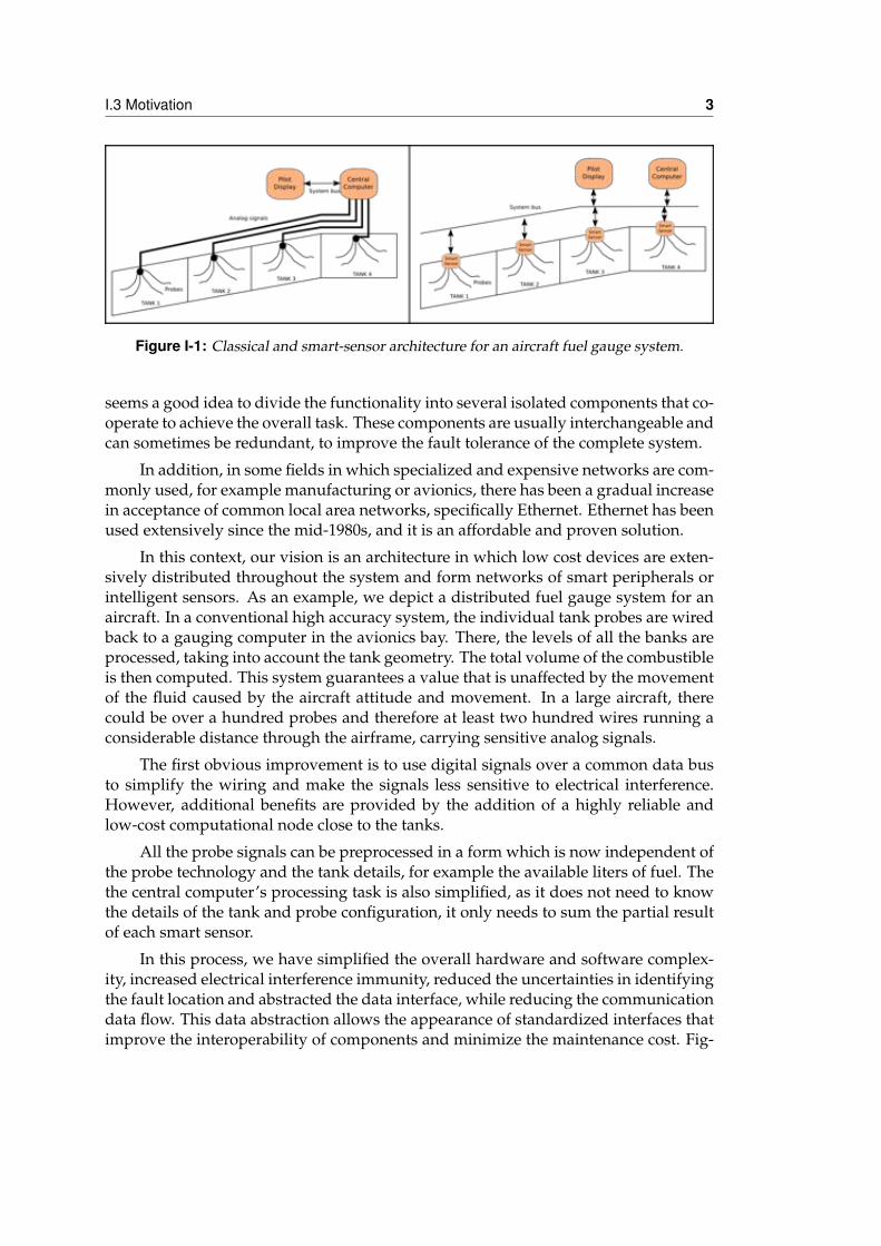
Figure I-1: Classical and smart-sensor architecture for an aircraft fuel gauge system.
seems a good idea to divide the functionality into several isolated components that co-operate to achieve the overall task. These components are usually interchangeable andcan sometimes be redundant, to improve the fault tolerance of the complete system.
In addition, in some fields in which specialized and expensive networks are com-monly used, for example manufacturing or avionics, there has been a gradual increasein acceptance of common local area networks, specifically Ethernet. Ethernet has beenused extensively since the mid-1980s, and it is an affordable and proven solution.
In this context, our vision is an architecture in which low cost devices are exten-sively distributed throughout the system and form networks of smart peripherals orintelligent sensors. As an example, we depict a distributed fuel gauge system for anaircraft. In a conventional high accuracy system, the individual tank probes are wiredback to a gauging computer in the avionics bay. There, the levels of all the banks areprocessed, taking into account the tank geometry. The total volume of the combustibleis then computed. This system guarantees a value that is unaffected by the movementof the fluid caused by the aircraft attitude and movement. In a large aircraft, therecould be over a hundred probes and therefore at least two hundred wires running aconsiderable distance through the airframe, carrying sensitive analog signals.
The first obvious improvement is to use digital signals over a common data busto simplify the wiring and make the signals less sensitive to electrical interference.However, additional benefits are provided by the addition of a highly reliable andlow-cost computational node close to the tanks.
All the probe signals can be preprocessed in a form which is now independent ofthe probe technology and the tank details, for example the available liters of fuel. Thethe central computer’s processing task is also simplified, as it does not need to knowthe details of the tank and probe configuration, it only needs to sum the partial resultof each smart sensor.
In this process, we have simplified the overall hardware and software complex-ity, increased electrical interference immunity, reduced the uncertainties in identifyingthe fault location and abstracted the data interface, while reducing the communicationdata flow. This data abstraction allows the appearance of standardized interfaces thatimprove the interoperability of components and minimize the maintenance cost. Fig-
4 Chapter I - Introduction
ure I-1 shows a fuel guage system, in a classical implementation and a smart sensorapproach.
This idea of distributed data sharing and computing is recurrent among differentactors. However, it has been deployed to varying degrees and using different tech-nologies and approaches. For example, expensive hardware proprietary solutions arefrequently used in the commercial scenario, for example ARINC 429 (ARINC, n.d.a)or ARINC 629 (ARINC, n.d.b). These avionics data buses allow the interchange ofdata between distributed units throughout the airframe. The physical and protocollayers are highly standardized. However, the application level is the developer’s re-sponsibility. This is because most of the units are hardware-based and their internalsare hidden by their manufacturers. With the appearance of AFDX (ARINC, 2005) andthe IMA (ARINC, 1997) concept, an effort has been made with the application layer,as most implementations can be fully software-based and executed in a shared buthighly partitioned environment. However, all these solutions are extremely expen-sive, proprietary and closely linked to the previous manufacturer’s investments.
In the literature, mainly CORBA and its real-time derivatives are used for com-municating distributed embedded control applications (Henning, 2008). CORBA is astandard that was originally designed to distribute enterprise applications. However,it has been extended and updated to support other types of embedded and real-timeapplications. Although Real-time CORBA offers substantial benefits, and the Real-time CORBA specification was integrated into the OMG standard several years ago, ithas not been universally adopted outside of academia, partly because of the followingissues. First, it is a large and complex technology with numerous features inheritedfrom its past use in the corporate sector. This causes both performance and mem-ory footprint overheads. Current monolithic CORBA Object Request Brokers (ORBs)usually generate an excessive run-time overhead and lack the predictability that isneeded for most embedded applications. Another related problem is the difficult orlack of customization needed in the ORBs so that they can be used in different embed-ded domains with strict requirements. Finally, it is a technology with a steep learningcurve that is mainly caused by the complexity of CORBA-C++ mapping, which it isthe language commonly used to develop applications with this technology.
If we focus on the field of unmanned aerial vehicles, usually only one or twosmall hardware systems are embedded inside the airframe, while the functionalitiesof the system are designed as monolithic blocks lying on one of the embedded devices.The communication between embedded devices is usually implemented using ad-hocprotocols over serial links (RS-232 or bus CAN) or, in some cases, Ethernet. Someacademic UAVs use CORBA for internal communication between embedded devices.However, inter-node communication is not needed in their software architecture, asonly one application is executed in each node. In this case, the use of CORBA is aweighty and unnecessary solution, as the communication requirements are minimum.
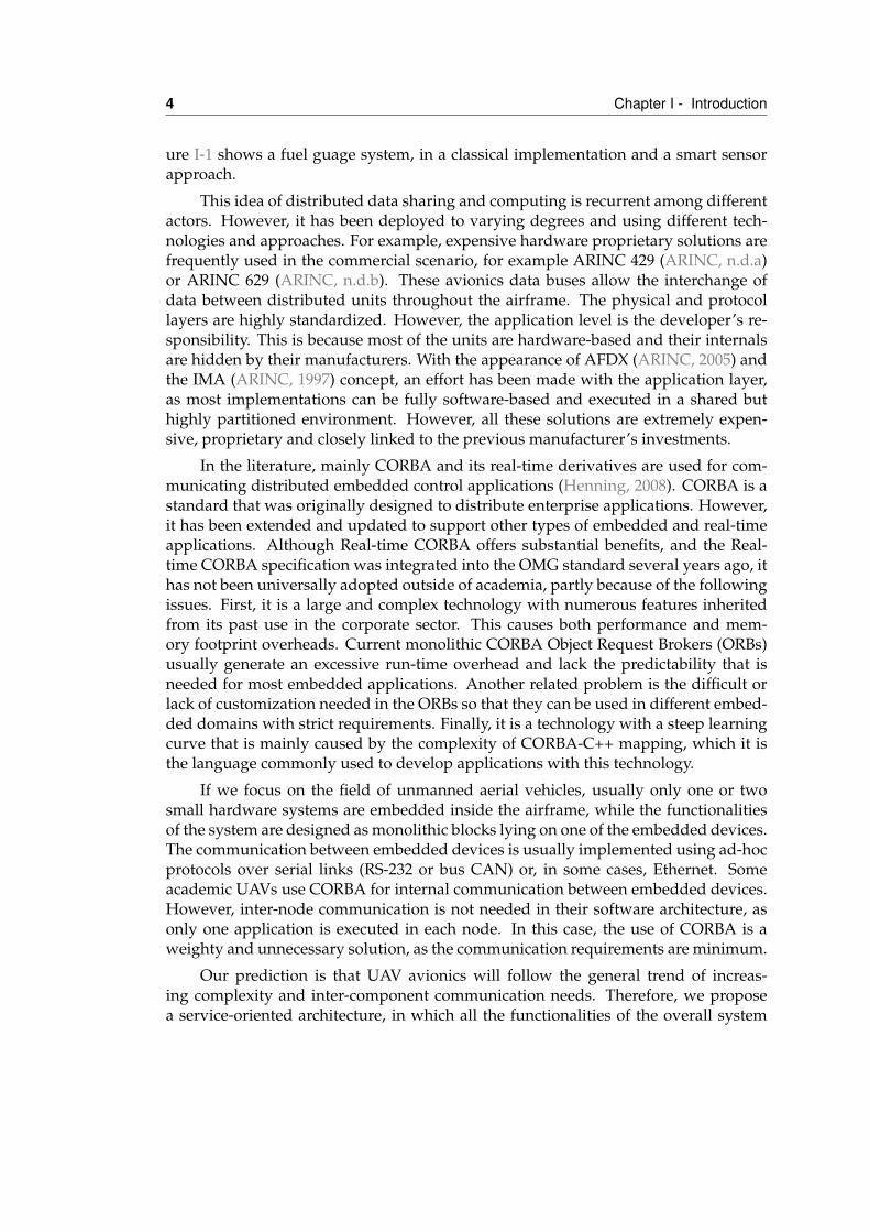
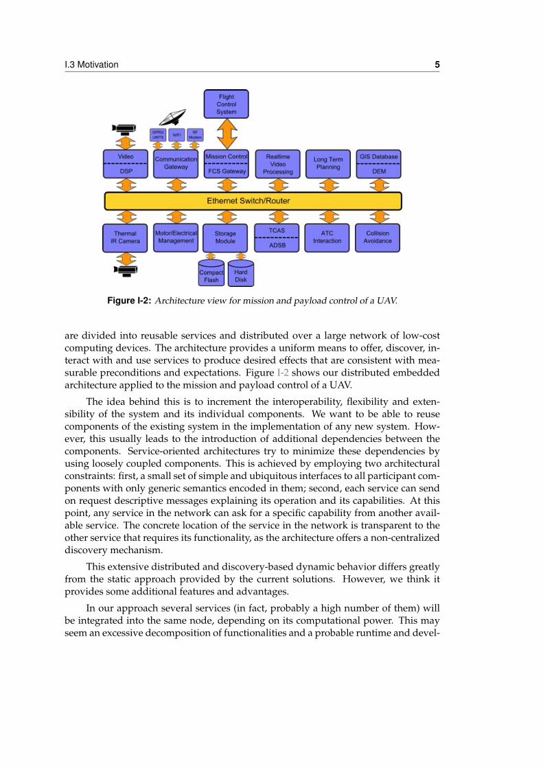
Our prediction is that UAV avionics will follow the general trend of increas-ing complexity and inter-component communication needs. Therefore, we proposea service-oriented architecture, in which all the functionalities of the overall system
I.3 Motivation 5
Figure I-2: Architecture view for mission and payload control of a UAV.
are divided into reusable services and distributed over a large network of low-costcomputing devices. The architecture provides a uniform means to offer, discover, in-teract with and use services to produce desired effects that are consistent with mea-surable preconditions and expectations. Figure I-2 shows our distributed embeddedarchitecture applied to the mission and payload control of a UAV.
The idea behind this is to increment the interoperability, flexibility and exten-sibility of the system and its individual components. We want to be able to reusecomponents of the existing system in the implementation of any new system. How-ever, this usually leads to the introduction of additional dependencies between thecomponents. Service-oriented architectures try to minimize these dependencies byusing loosely coupled components. This is achieved by employing two architecturalconstraints: first, a small set of simple and ubiquitous interfaces to all participant com-ponents with only generic semantics encoded in them; second, each service can sendon request descriptive messages explaining its operation and its capabilities. At thispoint, any service in the network can ask for a specific capability from another avail-able service. The concrete location of the service in the network is transparent to theother service that requires its functionality, as the architecture offers a non-centralizeddiscovery mechanism.
This extensive distributed and discovery-based dynamic behavior differs greatlyfrom the static approach provided by the current solutions. However, we think itprovides some additional features and advantages.
In our approach several services (in fact, probably a high number of them) willbe integrated into the same node, depending on its computational power. This mayseem an excessive decomposition of functionalities and a probable runtime and devel-
6 Chapter I - Introduction
opment overhead. However, it forces the developer to design the interactions betweenfunctionalities carefully, thus guaranteeing a separation of concerns. It also allowseasy and transparent implementation of desirable functionalities, such as: indepen-dence of the service deployment and configuration of the available hardware (thisconfiguration can be both static or dynamic), interoperability of services (e.g differentsensors or algorithms for the same functionality), fault tolerance (a service could bereplicated in different hardware nodes for redundancy) service migration (betweennodes in case of changes in the system’s needs), etc.
All of this reflects a distinguishing characteristic of our research: it is mainlyfocused on control applications, i.e. autopilots, and their real-time concerns. This sortof applications is highly critical and dependable and thus requires hard real-time andvalidation-verification assumptions. For ease of validation, the design is simplified tothe maximum and static behavior is preferred over dynamic.
However, we believe that this specific topic is being researched in depth, and weassume that some services will manage these critical operations in our system. Theinternal behavior and functioning of these services will obviously be hard real-timeand static. We focus on the rest of the non-critical, but essential, components of thesystem, and more specifically on mission and payload control.
I.4 Thesis objectivesUAVs are emerging as a valid commercial option that, like many other embeddedcomputer systems, have considerable limitations in space, power consumption, andcomputation capabilities. The use of current market devices and electronics aremandatory to keep a low cost solution, and this leads to a distributed architecture.However, we believe that there is a lack of software support to effectively develop thepotentialities of unmanned aircraft avionics.
The main thesis of this research is middleware-based architecture that is suitablefor operation as a flexible mission and payload controller in a UAV. The system is com-posed of a number of low-cost distributed computing devices connected by a network.The functionality of the system is divided into a set of reusable services that can be dis-tributed over the different computing nodes of the network. A middleware managesthe life cycle and the communication between services, and operates the global systemas a Distributed Embedded System.
Seen as a set of applications, the UAV is composed of a series of distributedelements, known as services, which operate on top of a middleware communicationframework. The communication primitives are mainly publish-subscribe based.However, two-way synchronous communication, i.e. remote procedure calls, are alsoavailable for the services. Additional efforts have been made in some specifics of theUAV avionics domain, in particular, interoperation with unreliable and high-latencypoint-to-point networks. Additionally, our view of the system not only comprisesthe hardware onboard a single airplane, but also the ground control station and its
I.5 Thesis outline 7
possible extension to other UAVs. This additional complexity is managed by specialnodes called communication gateways that act as transparent proxies for all requiredservices located in a physically separated fragment of the network.
Therefore, the main objectives of this thesis are:
1. The definition of a system architecture for embedded systems, and the commu-nication requirements for its distributed components.
2. The development and evaluation of a communication middleware for this archi-tecture.
3. The design of a communication gateway that abstracts and manages the compo-nent communication among nodes in different local networks.
I.5 Thesis outlineThe material in the present document is organized into seven chapters which are sum-marized as follows:
• Chapter II presents the state of the art in middleware applied to avionics sys-tems. It shows the great diversity of the possible approaches and the inherentcomplexity of such systems.
• Chapter III describes the context of operation and presents several functionaland non-functional requirements. The described context covers the most neededfunctionality that one can expect from embedded applications and most specifi-cally UAV avionics.
• Chapter IV defines the service oriented architecture that will be used to imple-ment in a modular and reusable manner distributed embedded systems. Thedefinition of a service, their communication mechanisms and its naming schemeis carefully explained.
• Chapter V tackles the design and implementation of the Marea middleware andtheir communication primitives.
• Chapter VI describes the methodology and processes to convert a set of Mareaservices into a UAS configuration that can perform an specific UAV mission.
• Chapter VII shows an specific component added to Marea to support unrealiablepoint-to-point links typical of UAS communication systems. The Communica-tion Gateway makes the different network links transparent to Marea servicesand allow multiple networks to be used for link redundancy.
• Chapter VIII demostrates Marea applicability in the UAV avionics field by ana-lyzing its performance and comparing it with typical UAV requirements.

8 Chapter I - Introduction
• Chapter IX shows two application examples where Marea has been succesfullyapplied. First, ISIS, a multi-UAV simulator implemented over Marea is pre-sented. Next, the overall architecture is demonstrated by means of a wild landfire remote sensing application developed to support firefight ers.
• Finally, chapter X gives the conclusions that are drawn from this work and pointsout some future work that could be done in the direction of the research pre-sented.
IIPrevious work
II.1 IntroductionThis section presents previous research in the area of avionics for civil use, in partic-ular in the area of middleware for this type of embedded systems. For a more gen-eral review of middleware refer to (Schmidt, 2002) which presents the challenges andavailable technical solutions of several middleware approaches for distributed andembedded systems. It is a nice and concise survey on middleware uses on mission-critical dynamic domains.
Middleware is a very broad term and covers many software developments. Mostof them are developed for a very specific and concrete function. For example, (Bakeret al. , 2006) report presents the experience of an open implementation of a middle-ware for Java applications, named Ovm. (Honvault et al. , 2005) presents the workdeveloped under the A3M project. A novel middleware focus on space applicationsis developed. The main interest come from the requirements met by the middleware:real-time and dependability. Two protocols are develop and verified under a Real-Time OS simulator. Middleware specially targeted to sensors are (Zhang et al. , 2006)and (Grace et al. , 2006). In (Zhang et al. , 2006) Zhang et al. have developed a mid-
9
10 Chapter II - Previous work
dleware to manage large number of sensors that connect wireless with delay tolerancebut power management constraints. Diversity of sensors, large number of them andfinal application developed are main target of this middleware. While (Grace et al. ,2006) presents the extension of the Gridkit sensor middleware to cover the dynamicconfiguration and customization of a large sensor network.
Publish/Subscribe is a communication paradigm of growing popularity for in-formation dissemination in distributed systems. Some relevant systems are Gryphon(IBM, n.d.), Hermes (Pietzuch & Bacon, 2003), JEDI (Cugola et al. , 2002), SIENA(Carzaniga et al. , 2003), TERA (Baldoni et al. , 2007) and Scribe (Castro et al. , 2002).For a review on this paradigm refer to (Baldoni et al. , 2003). Most of this researchis focused on large scale system where information dissemination without multicastcapabilities implies complex routing techniques on the application level. In our case,local networks inside the embedded system will be used so while using the sameparadigm, we can rely in the multicast capabilities of the network.
For the rest of the chapter we are going to focus on the middleware families andtechnologies that can be directly applied in the avionics field.
II.2 CORBAThe Common Object Request Broker Architecture (CORBA) is a standard defined bythe Object Management Group (OMG) that enables software components written inmultiple computer languages and running on multiple computers to interoperate.More specifically, CORBA is a mechanism in software for normalizing the method-call semantics between application objects that reside either in the same address space(application) or remote address space (same host, or remote host on a network). Ver-sion 1.0 was released in October 1991. CORBA uses an interface definition language(IDL) to specify the interfaces that objects will present to the outside world. CORBAthen specifies a mapping from IDL to a specific implementation language like C++ orJava.
The CORBA specification dictates that there shall be an Object Request Broker(ORB) through which the application interacts with other objects. In practice, the ap-plication simply initializes the ORB, and accesses an internal Object Adapter, whichmanages object reference counting, object instantiation policies, and object lifetimepolicies. The Object Adapter is used to register instances of the generated code classes.Generated code classes are the result of compiling the user IDL code, which translatesthe high-level interface definition into an OS- and language-specific class base for useby the user application. A language mapping requires the developer to create someIDL code that represents the interfaces to his objects. Typically, a CORBA implemen-tation comes with a tool called an IDL compiler which converts the user’s IDL codeinto some language-specific generated code. A traditional compiler then compiles thegenerated code to create the linkable-object files for the application.
II.2 CORBA 11
II.2.1 CORBA Component Model (CCM)CORBA Component Model (CCM) is an addition to the family of CORBA definitions.It was introduced with CORBA 3 and it describes a standard application frameworkfor CORBA components. It provides an abstraction of entities that can provide andaccept services through well-defined named interfaces called ports. The CCM has acomponent container, where software components can be deployed. The container of-fers a set of services that the components can use. These services include notification,authentication, persistence and transaction processing. These are the most-used ser-vices any distributed system requires, specially in the field of enterprise applications,and, by moving the implementation of these services from the component container,the complexity of the components is dramatically reduced.
II.2.2 BenefitsCORBA aims to bring many benefits that no other single technology brings in onepackage. These benefits include language- and OS-independence, freedom fromtechnology-linked implementations, strong data-typing, high level of tunability, andfreedom from the details of distributed data transfers.
Language and OS Independence: CORBA at the outset was designed to free engi-neers from the hang-ups and limitations of considering their designs based ona particular software language or operating system. Currently there are manylanguages supported by various CORBA providers, the most popular are Javaand C++ running on virtually all operating systems.
Strong Data Typing: CORBA Interface Definition Language provides the mechanismto ensure that user-code conforms to method names, return, parameter-typesand exceptions.
High Tune-ability: There are many implementations available that have many op-tions for tuning the threading and connection management features. Not allimplementations provide the same features. This is up to the implementor.
Compression: CORBA marshals its data in a efficient binary form called IIOP (Inter-net Inter ORB Protocol) and supports compression.
II.2.3 ProblemsWhile CORBA promised to deliver much in the way code was written and softwareconstructed, it has been the subject of much criticism (Chappell, 1998). Some of thefailures were due to the implementations and the process by which CORBA was cre-ated as a standard, others reflect problems in the politics and business of implement-ing a software standard. These problems led to a significant decline in CORBA useand adoption in new projects and areas.
12 Chapter II - Previous work
Complexity and design deficiencies: The creation of the CORBA standard is also of-ten cited for its process of design by committee. There was no process to arbi-trate between conflicting proposals or to decide on the hierarchy of problemsto tackle. Thus the standard was created by taking a union of the features inall proposals with no regard to their coherence (Henning, 2008). This made thespecification very complex, expensive to implement entirely and often ambigu-ous. A design committee composed largely of vendors of the standard imple-mentation, created a disincentive to make a comprehensive standard. This wasbecause standards and interoperability increased competition and eased cus-tomers’ movement between alternative implementations. This led to much po-litical fighting within the committee, and frequent releases of revisions of theCORBA standard that were impossible to use without proprietary extensions(Chappell, 1998).
Problems with implementations: Through its history, CORBA has been plagued byshortcomings in its implementations. Often there have been few implementa-tions matching all of the critical elements of the specification (Henning, 2008),and existing implementations were incomplete or inadequate. As there wereno requirements to provide a reference implementation, members were free topropose features which were never tested for usefulness or implementability.Implementations were further hindered by the general tendency of the standardto be verbose, and the common practice of compromising by adopting the sumof all submitted proposals, which often created APIs that were incoherent anddifficult to use, even if the individual proposals were perfectly reasonable.
Location transparency: CORBA’s notion of location transparency has been criticized;that is, that objects residing in the same address space and accessible with asimple function call are treated the same as objects residing elsewhere (differentprocesses on the same machine, or different machines). This notion is flawed ifone requires all local accesses to be as complicated as the most complex remotescenario. However, CORBA does not place a restriction on the complexity of thecalls. Many implementations provide for recursive thread/connection seman-tics. I.e. Obj A calls Obj B, which in turn calls Obj A back, before returning.
Firewalls CORBA (more precisely, IIOP) uses raw TCP/IP connections in order totransmit data. However, if the client is behind a very restrictive firewall or trans-parent proxy server environment that only allows HTTP connections to the out-side through port 80, communication may be impossible. At one time, it was dif-ficult even to force implementations to use a single standard port — they tendedto pick multiple random ports instead. Due to such difficulties, some users havemade increasing use of web services instead of CORBA.
II.2.4 Real-time CorbaThe Real-time CORBA (RT-CORBA) 1.2 specification defines standard features thatsupport end-to-end predictability for operations in fixed-priority CORBA applica-
II.2 CORBA 13
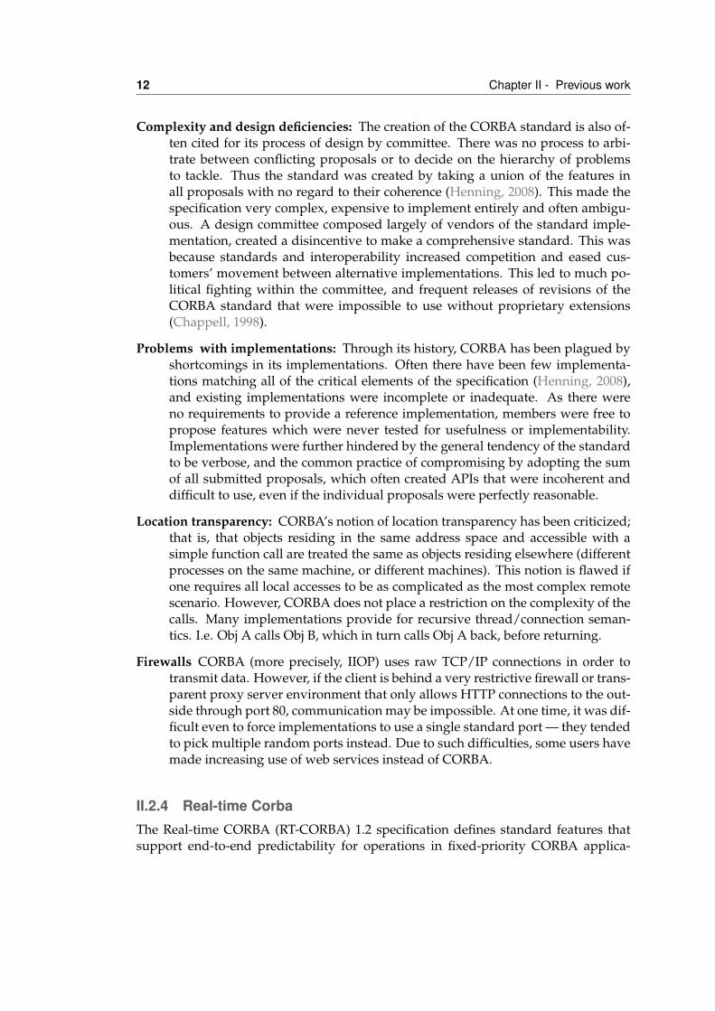
Figure II-1: Real-time CORBA Architecture
tions. This specification extends the existing CORBA standard and the OMG Mes-saging specification. In particular, RT-CORBA 1.2 leverages features from GIOP/IIOPversion 1.1 and the Messaging specification’s QoS policy framework. The RT-CORBAspecification identifies capabilities that must be vertically and horizontally integratedand managed by ORB endsystems to ensure end-to-end predictable behavior for ac-tivities that flow between CORBA clients and servers. On figure II-1 it can be seen thearchitecture of a Real-time CORBA ORB.
The following summarises these capabilities, starting from the lowest level ofabstraction and building up to higher-level services and applications.
Communication infrastructure resource management: An RT-CORBA endsystemmust leverage policies and mechanisms in the underlying communication in-frastructure that support resource guarantees. This support can range from man-aging the choice of the connection used for a particular invocation to exploitingadvanced QoS features, such as controlling the ATM virtual circuit cell pacingrate.
OS scheduling mechanisms: ORBs exploit OS mechanisms to schedule application-level activities end-to-end. Since the RT-CORBA specification targets fixed-priority real-time systems, these mechanisms correspond to managing OS threadscheduling priorities. The RT-CORBA specification focuses on operating sys-tems that allow applications to specify scheduling priorities and policies. Forexample, the real-time extensions in IEEE POSIX 1003.1c define a static priorityFIFO scheduling policy that meets this requirement.
14 Chapter II - Previous work
Real-Time ORB endsystem: ORBs are responsible for communicating requests be-tween clients and servers transparently. A real-time ORB endsystem must pro-vide standard interfaces that allow applications to specify their resource require-ments to the ORB. The policy framework defined by the OMG Messaging specifi-cation allows applications to configure ORB endsystem resources, such as threadpriorities, buffers for message queueing, transport-level connections, and net-work signaling, in order to control ORB behavior.
Real-time services and applications: Having a real-time ORB manage endsystemand communication resources only provides a partial solution. Real-timeCORBA ORBs must also preserve efficient, scalable, and predictable behaviorend-to-end for higher-level services and application components. For example,a global scheduling service can be used to manage and schedule distributed re-sources. Such a scheduling service can interact with an ORB to provide mech-anisms that support the specification and enforcement of end-to-end operationtiming behavior. Application developers can then structure their programs toexploit the features exported by the real-time ORB and its associated higher-level services. To manage these capabilities, RT-CORBA defines standard inter-faces and QoS policies that allow applications to configure and control (1) pro-cessor resources via thread pools, priority mechanisms, intra-process mutexes,and a global scheduling service, (2) communication resources via protocol prop-erties and explicit bindings, and (3) memory resources via buffering requests inqueues and bounding the size of thread pools. Applications typically specifythese real-time QoS policies along with other policies when they call standardORB operations, such as create POA or validate connection. For instance, whenan object reference is created using a QoS-enabled POA, the POA ensures thatany server-side policies that affect client-side requests are embedded within atagged component in the object reference. This enables clients who invoke op-erations on such object references to honor the policies required by the targetobject.
II.2.5 Data Distribution ServiceThe OMG Data-Distribution Service for Real-Time Systems (DDS) is an open mid-dleware standard directly addressing publish-subscribe communications for real-timeand embedded systems. DDS introduces a virtual Global Data Space where applica-tions can share information by simply reading and writing data-objects addressed bymeans of an application-defined name (Topic) and a key. DDS features fine and exten-sive control of QoS parameters, including reliability, bandwidth, delivery deadlines,and resource limits.
DDS targets real-time systems; the API and Quality of Service (QoS) are chosen tobalance predictable behavior and implementation efficiency/performance. The DDSspecification describes two levels of interfaces: A lower level Data-Centric Publish-Subscribe (DCPS) that is targeted towards the efficient delivery of the proper informa-tion to the proper recipients; and an optional higher-level Data-Local Reconstruction
II.2 CORBA 15
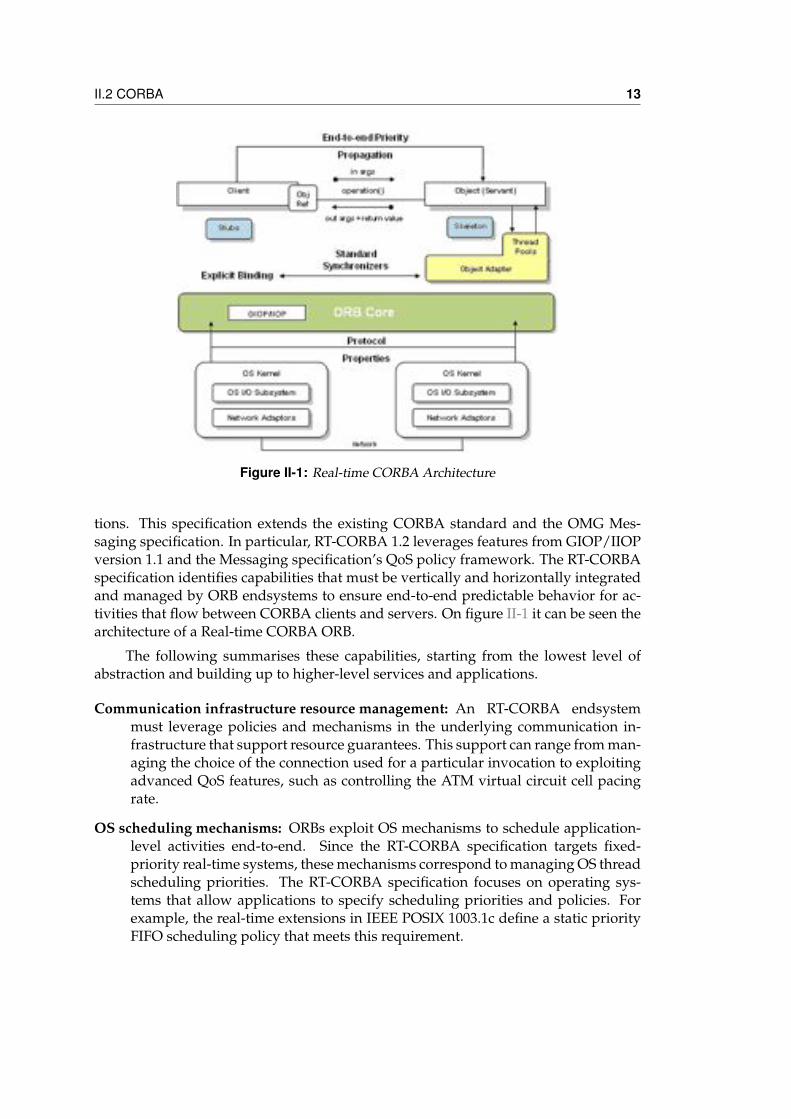
Figure II-2: OMG DDS Architecture
Layer (DLRL), which allows for a simpler integration into the application layer. TheDCPS model builds on the idea of a “global data space” of data-objects that any en-tity can access. Applications that need data from this space declare that they want tosubscribe to the data, and applications that want to modify data in the space declarethat they want to publish the data. A data-object in the space is uniquely identifiedby its keys and topic, and each topic must have a specific type. There may be sev-eral topics of a given type. A global data space is identified by its domain id, eachsubscription/publication must belong to the same domain to communicate. FigureII-2 illustrates the overall data-centric publish-subscribe model, which consists of thefollowing entities: DomainParticipant, DataWriter, DataReader, Publisher, Subscriber,and Topic.
Publisher represents the objects responsible for data issuance. A Publisher maypublish data of different data types. A DataWriter is a typed facade to a publisher;participants use DataWriter(s) to communicate the value of and changes to data of agiven type. Once new data values have been communicated to the publisher, it is thePublisher’s responsibility to determine when it is appropriate to issue the correspond-ing message and to actually perform the issuance (the Publisher will do this accordingto its QoS, or the QoS attached to the corresponding DataWriter, and/or its internalstate).
A Subscriber receives published data and makes it available to the participant. ASubscriber may receive and dispatch data of different specified types. To access thereceived data, the participant must use a typed DataReader attached to the subscriber.The association of a DataWriter object (representing a publication) with DataReaderobjects (representing the subscriptions) is done by means of the Topic. A Topic asso-ciates a name (unique in the system), a data type, and QoS related to the data itself.The type definition provides enough information for the service to manipulate the
16 Chapter II - Previous work
data (for example serialize it into a network-format for transmission).
The DDS middleware handles the actual distribution of data on behalf of a userapplication. The distribution of the data is controlled by user settable Quality of Ser-vice (QoS).
II.2.6 Research on CORBALot of research has been done in both the industry and the academia regardingCORBA technologies. For example, (Hoosier et al. , 2006) presents Bogor, a modelchecking framework that models the semantics of Real-Time CORBA using a gen-eral complexity checking model. In the case of (Edwards et al. , 2004) Edwards et al.present how to automate the configuration of services in presence of quality of ser-vice (QoS) capabilities. The testbed is an avionics system with 50 components of theCORBA Component Model.
Finally, there is a SOA approach in (Broy et al. , 2007) and (Detmold et al. , 2006)similar to our proposal. The work in (Broy et al. , 2007) presents an extension of theFOCUS theory; this is a formalism to describe SOA services. They compare SOA ser-vices against CORBA objects and show the benefits of the service oriented approach.They target application, though, is not in the aerial domain but on the automotive. In(Detmold et al. , 2006) it is presented a novel middleware based also on service ori-ented model with publish/subscribe messaging but with the particularity of addingvideo processing capabilities. The middleware is tested on a network of thousands ofsensors cameras.
Other testbeds of the above mentioned works are mainly done for general avion-ics systems. Only (Baker et al. , 2006) uses a testbed of flight demonstrations with asmall UAV. This work is specially interesting because is using a CORBA middlewarelayer over a Java virtual Machine.
Specific avionics buses testbeds are in (Doerr & Sharp, 2000), which presents thereengineering of a McDonnell Douglas software to be able to reuse the system ele-ments across platforms and introduce a new software physical architecture for theproduct line development. Also (Jung & Hatcliff, 2007) uses the Boeing Bold Strokeavionics to enhance the CORBA Component Model middleware and to study the cor-relation between events to detect special situations known as semantic events.
In our approach the middleware is developed for a high level mission design,concentrating efforts in functionality more than in Real-time issues. Like in (Subra-monian et al. , 2002) which shows the advantages of reducing CORBA functionalities(NEST and OEP) in benefit of efficiency, we believe that a small number of really usefulfunctionalities are more important and efficient that large implementations of todaymiddleware. Also (Demir et al. , 2007) argues that due to the complexity and complete-ness of many middleware platforms efficiency may be compromise. The paper studiesseveral ways to bypass the middleware layer (or part of it) to improve efficiency.
II.3 Avionics 17
II.3 AvionicsModern digital avionics are mainly implemented as distributed computing architec-tures. Two different approaches are given: federated and modular. Federated avionicsarchitectures appeared on the early 80s. In this architecture, distribution is under-stood as self-contained, independent packaging of avionics functionalities. Federatedavionics have a univocal relation between functionalities and resources: Every avion-ics functionality is integrated into a back-box and none resource is shared betweenavionics systems other than the communication buses. A typical example of federatedavionics is a standalone Flight Control Systems like AP04 (UAV Navigation, n.d.) orPiccolo (B.Vaglienti et al. , 2005).
Since 2001, with the developments of Boeing 787 and later Airbus A380, the civildistributed avionics architectures are moving to the concept of Integrated ModularAvionics (IMA) (Spitzer, December 2006). In the IMA approach the avionics func-tionalities are distributed into logical Partitions which may be allocated into a samephysical computing Module or into a different one. A computing Module is a hard-ware board with one or more micro-processors. All available Modules, connectedthrough avionics buses, are highly integrated by a common software layer, typicallythe ARINC 653 APEX (ARINC, n.d.c). Airbus calls IMA Modules as Modular AvionicsUnits while Boeing names them Common Core Systems. In general IMA Modules areLine Replaceable Units (LRU) that follow the ARINC 600 physical standard. For theirconnectivity any avionics bus can be used (ARINC 429, AFDX, etc.).
The main differences between both architectures are the possibility of sharing re-sources between avionics systems and the avionics interfaces. While federated avion-ics do not share computing resources, IMA avionics share computing resources andalso displays, other devices, and even buses. On the other side, avionics interfaces onfederated avionics are limited to a number of hardware connectors, while in IMA theinterfaces are mainly software definitions, and a large number of them may exist.
II.3.1 ARINC 429ARINC 429 is the technical standard for the predominant avionics data bus used onmost higher-end commercial and transport aircraft. It defines the physical and elec-trical interfaces of a two-wire data bus and a data protocol to support an aircraft’savionics data network (ADN). This ADN can be found on a variety of aircraft fromboth Boeing and Airbus, including the B737, B747, B757, B767 and Airbus A330, A340,A380 and the upcoming A350.
ARINC 429 is application-specific standard for aircraft avionics. It’s a self clock-ing self synchronizing unidirectional data bus (Tx and Rx are on separate ports)known as the Mark 33 Digital Information Transfer System (DITS). The physical con-nection wires are twisted pairs carrying balanced differential signaling. Data wordsare 32 bits in length and most messages consist of a single data word. Messages aretransmitted at either 12.5 or 100 kbit/s to other system elements that are monitoringthe bus messages. The transmitter constantly transmits either 32-bit data words or
18 Chapter II - Previous work
the NULL state. A single wire pair is limited to one transmitter and no more than20 receivers. The protocol allows for self-clocking at the receiver end, thus eliminat-ing the need to transmit clocking data that existed in previous (6 wire) protocols likeARINC-568. ARINC 429 is a low cost less capable alternative to MIL-STD-1553.
Label guidelines are provided as part of the ARINC 429 specification, for variousequipment types. Each aircraft will contain a number of different systems, such asflight management computers, inertial reference systems, air data computers, radaraltimeters, radios, and GPS sensors. For each type of equipment, a set of standardparameters is defined, which is common across all manufacturers and models. Forexample, any air data computer will provide the barometric altitude of the aircraft aslabel 203. This allows some degree of interchangeability of parts, as all air data com-puters behave, for the most part, in the same way. There are only a limited number oflabels, though, and so label 203 may have some completely different meaning if sentby a GPS sensor, for example. Very commonly-needed aircraft parameters, however,use the same label regardless of source. Also, as with any specification, each manufac-turer has slight differences from the formal specification, such as by providing extradata above and beyond the specification, leaving out some data recommended by thespecification, or other various changes.
II.3.2 ARINC 664 / AFDXAvionics Full-Duplex Switched Ethernet (AFDX) is a data network for safety-criticalapplications that utilizes dedicated bandwidth while providing deterministic Qual-ity of Service (QoS). AFDX is based on IEEE 802.3 Ethernet technology and utilizescommercial off-the-shelf (COTS) components. It is described specifically by Part 7 ofthe ARINC 664 Specification, as a special case of a profiled version of an IEEE 802.3network per parts 1 & 2, which defines how Commercial Off-the-Shelf networkingcomponents will be used for future generation Aircraft Data Networks (ADN). The sixprimary aspects of AFDX include full duplex, redundancy, deterministic, high speedperformance, switched and profiled network.
Prior to AFDX, Aircraft Data Networks utilized primarily the ARINC 429 stan-dard. This standard, developed over thirty years ago and still widely used today, hasproven to be highly reliable in safety critical applications. As shown in the previoussection, ARINC 429 operates in such a way that its single transmitter communicatesin a point-to-point connection, thus requiring a significant amount of wiring whichamounts to added weight.
Another standard, ARINC 629, introduced by Boeing for the 777 provides in-creased data speeds of up to 2 Mbit/s and allowing a maximum of 120 data terminals.This ADN operates without the use of a bus controller thereby increasing the relia-bility of the network architecture. The draw back of this system is that it requirescustom hardware which can add significant cost to the aircraft. Because of this, othermanufactures did not openly accept the ARINC 629 standard.
ARINC 664 is defined as the next-generation aircraft data network. AFDX builds
II.3 Avionics 19
on this standard and it was developed by Airbus Industries for the A380. It has sincebeen accepted by Boeing and is used on the Boeing 787 Dreamliner. AFDX bridges thegap on reliability of guaranteed bandwidth from the original ARINC 664 standard.It utilizes a cascaded star topology network, where each switch can be bridged to-gether to other switches on the network. By utilizing this form of network structure,AFDX is able to significantly reduce wire runs thus reducing overall aircraft weight.Additionally, AFDX provides dual link redundancy and Quality of Service (QoS).
AFDX adopted concepts (token bucket) from the telecom standard, Asyn-chronous Transfer Mode (ATM), to fix the shortcomings of IEEE 802.3 Ethernet. Byadding key elements from Asynchronous Transfer Mode (ATM) to those alreadyfound in Ethernet, and constraining the specification of various options, a highly re-liable Full-Duplex deterministic network is created providing guaranteed bandwidthand Quality of Service. It reuses existing functional elements common in computerdata networks at the following OSI Reference Model layers :
• Data Link: MAC and Virtual Link addressing concept.
• Network: IP and ICMP.
• Transport: UDP and optionally TCP.
• Application: Sampling, Queuing, SAP, TFTP and SNMP.
The central feature of an AFDX network are its Virtual Links (VL). In one abstrac-tion, it is possible to visualise the VLs as an ARINC 429 style network each with onesource and one or more destinations. Virtual Links are unidirectional logic path fromthe source end-system to all of the destination end- systems. Unlike that of a tradi-tional Ethernet switch which switches frames based on the Ethernet destination orMAC address, AFDX routes packets using a Virtual Link ID. The Virtual Link ID isa 16-bit Unsigned integer value that follows the constant 32-bit field. The switchesare designed to route an incoming frame from one, and only one, End System to apredetermined set of End Systems. There can be one or more receiving End Systemsconnected within each Virtual Link. Bi directional comms must therefore require thespecification of a complimentary VL.
Each VL is frozen in specification to ensure that the network has a designed max-imum traffic, hence performance. Also the switch, having a VL configuration tableloaded, can reject any erroneous data transmission that may otherwise swamp otherbranches of the network. Additionally, there can be sub-virtual links (sub-VLs) thatare designed to carry less critical data. Sub-virtual links are assigned to a particularVirtual Link. Data is read in a round robin sequence among the Virtual Links withdata to transmit. Also sub-virtual links do not provide guaranteed bandwidth.
II.3.3 ARINC 653ARINC 653 (Avionics Application Standard Software Interface) is a software specifi-cation for space and time partitioning in Safety-critical avionics Real-time operating
20 Chapter II - Previous work
systems. It allows to host multiple applications of different software levels on thesame hardware in the context of a Integrated Modular Avionics architecture.
In order to decouple the RTOS platform from the application software, ARINC653 defines an API called APplication EXecutive (APEX). Each application software iscalled a partition and has its own memory space. Each partition has a dedicated timeslot allocated by the APEX API, also multitasking is allowed within a partition.
The APEX API provides services to manage partitions, processes and timing, aswell as partition/process communication and error handling. No ARINC 653 servicesare provided for the memory management of partitions. Each partition has to han-dle its own memory (still under the constraints of memory partitioning enforced byARINC 653).
Partitioning One purpose of a core module in an IMA system is to support one ormore avionics applications and to allow their independent execution. This canbe correctly achieved if the system provides partitioning, i.e., a functional sepa-ration of the avionics applications, usually for fault containment (to prevent anypartitioned function from causing a failure in another partitioned function) andfor ease of verification, validation and certification. A partition is basically thesame as a program in a single application environment: it comprises data, itsown context, configuration attributes, etc. For large applications, the concept ofmultiple partitions relating to a single application is recognized.
APEX interface APEX interface is located between the application software and theOS. It defines a set of facilities provided by the system for application software tocontrol the scheduling, communication, and the status information of its internalprocessing elements. APEX also provides a common logical environment forthe application software that enables independently- produced applications toexecute together on the same hardware.
Scheduling Specification differences between partition scheduling and processscheduling. Scheduling of partitions is strictly deterministic over time. The Sys-tem Integrator assigns one or more time windows to each partition. This is donein the fixed configuration within the core module. The scheduling algorithmruns repetitively with a fixed periodicity. Partitions have no priority by them-selves. The scheduling unit is an APEX process. Each process has a priority. Thescheduling algorithm is priority preemptive. During any process reschedulingevent, the os always selects the highest priority process in the ready state withinthe partition to receive processor resources. If several processes have the samecurrent priority, the OS selects the oldest one.
Time Management A time capacity is associated with each process, and representsthe response time given to the process for satisfying its processing requirements.When a process is started, its deadline is set to the value of the current time plusthe time capacity. This deadline time may be postponed by means of serviceREPLENISH. This capacity is an absolute duration of time, not an execution
II.3 Avionics 21
time. This means that a deadline overrun will occur even when the process isnot running inside or outside the partition window, but will be acted upon onlyinside a partition window of its own partition.
Interpartition and Intrapartition communication Interpartition communication isdefined as the communication among two or more partitions executing eitheron the same module or on different modules. It may also mean communica-tion between APEX partitions and external equipment. Interpartition commu-nication is conducted via messages. Intrapartition communication mechanismsallow processes to communicate and synchronize with each other. All intraparti-tion message passing mechanisms must ensure atomic message access.
II.3.4 Research on avionicsClassical papers on avionics buses are focus on Real-time capabilities, in particular onflight control and verification. If previous research targeted on the military domain,nowadays the challenge is the civil avionics because their applications must be eas-ily adaptable and reconfigurable. Also it is important to base solutions on low-costand low-resources hardware. In these applications services and sensors are a key is-sue: Their initial configuration, their description, their verification or their dynamicreconfiguration are several of the research targets.
Digital avionics, and specially integrated modular avionics, has been an activeresearch topic the last years in both the industry and the academia:
GE Avionics has shared its large experience on IMA on different papers: Watkins& Walter (C.B.Watkins & R.Walter, October 2007) give some advices for a successfultransition from avionics federated architectures into IMA: 1) work hard in the InterfaceControl Document before any implementation in order to define clearly the systeminterfaces and 2) decide for an Open IMA system.
Littlefield & Viswanathan (J.Littlefield & R.Wiswanathan, October 2007) go fur-ther in the proposal of an Open IMA system and present a notional architecture frame-work for IMA, the GOIMA, based on GOA (Generic Open Architecture (Society ofAutomotive Engineers (SAE), n.d.)) to extend the opportunities of the existing AR-INC 653 open standard. In the GOIMA three interfaces standardize the interactionbetween the 4 levels defined from Physical up to Applications: A Common HardwareInterface, a Common Platform Abstraction Layer and an Enhanced APEX interfacethat makes IMA applications independent format the actual Operating System. Theyclaim that the extensive use of standards in other industries like automotive and tele-coms has promoted reusability (COTS components), reliability and decreased productdevelopment cycle times. In this paper the IMA hardware is assumed to be hetero-geneous, and level 2 creates an abstraction layer for them (they call it PAL -PlatformAbstractions Layer-) in the same way we have done with the autopilot and the VAS.
Garside & Pighetti (R.Garside & F.J.Pighetti, October 2007) present the IMA inte-gration challenges and contrast them with the previous avionics integration approach:
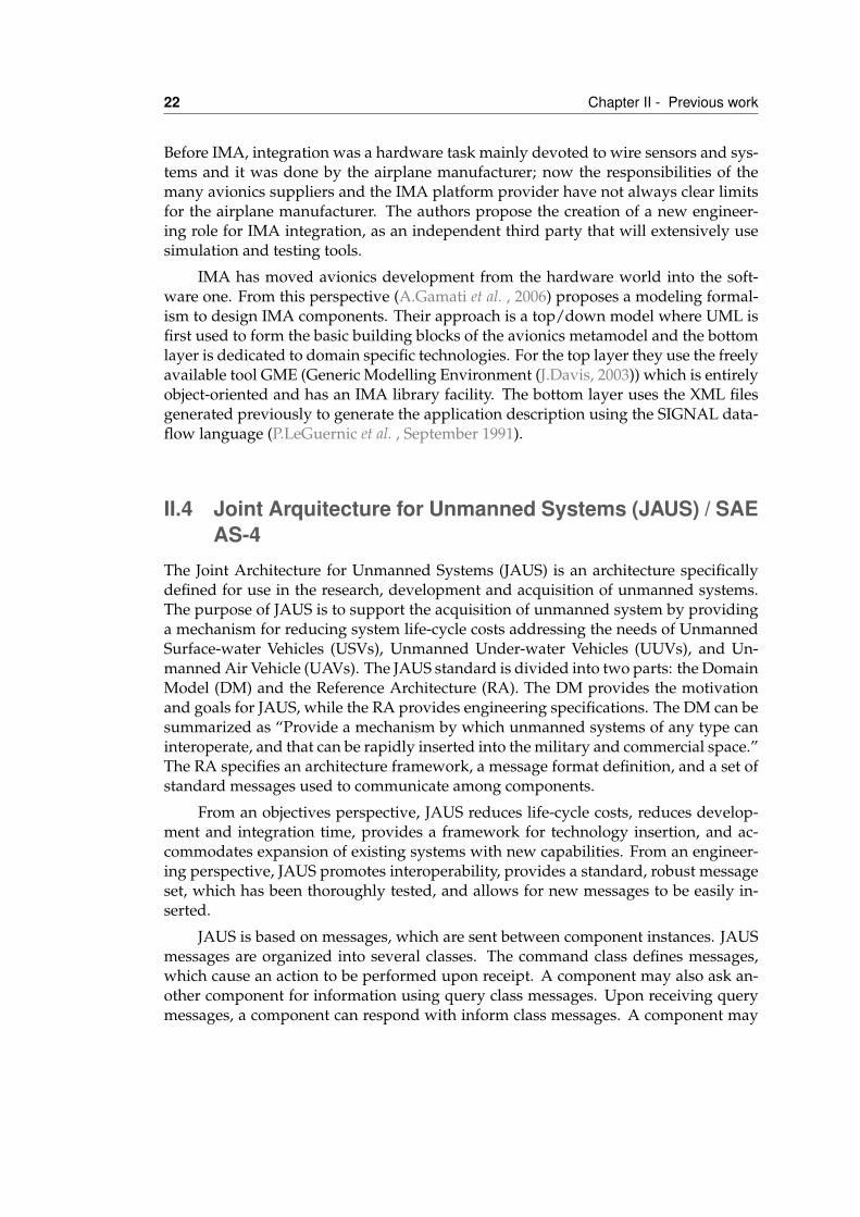
22 Chapter II - Previous work
Before IMA, integration was a hardware task mainly devoted to wire sensors and sys-tems and it was done by the airplane manufacturer; now the responsibilities of themany avionics suppliers and the IMA platform provider have not always clear limitsfor the airplane manufacturer. The authors propose the creation of a new engineer-ing role for IMA integration, as an independent third party that will extensively usesimulation and testing tools.
IMA has moved avionics development from the hardware world into the soft-ware one. From this perspective (A.Gamati et al. , 2006) proposes a modeling formal-ism to design IMA components. Their approach is a top/down model where UML isfirst used to form the basic building blocks of the avionics metamodel and the bottomlayer is dedicated to domain specific technologies. For the top layer they use the freelyavailable tool GME (Generic Modelling Environment (J.Davis, 2003)) which is entirelyobject-oriented and has an IMA library facility. The bottom layer uses the XML filesgenerated previously to generate the application description using the SIGNAL data-flow language (P.LeGuernic et al. , September 1991).
II.4 Joint Arquitecture for Unmanned Systems (JAUS) / SAEAS-4
The Joint Architecture for Unmanned Systems (JAUS) is an architecture specificallydefined for use in the research, development and acquisition of unmanned systems.The purpose of JAUS is to support the acquisition of unmanned system by providinga mechanism for reducing system life-cycle costs addressing the needs of UnmannedSurface-water Vehicles (USVs), Unmanned Under-water Vehicles (UUVs), and Un-manned Air Vehicle (UAVs). The JAUS standard is divided into two parts: the DomainModel (DM) and the Reference Architecture (RA). The DM provides the motivationand goals for JAUS, while the RA provides engineering specifications. The DM can besummarized as “Provide a mechanism by which unmanned systems of any type caninteroperate, and that can be rapidly inserted into the military and commercial space.”The RA specifies an architecture framework, a message format definition, and a set ofstandard messages used to communicate among components.
From an objectives perspective, JAUS reduces life-cycle costs, reduces develop-ment and integration time, provides a framework for technology insertion, and ac-commodates expansion of existing systems with new capabilities. From an engineer-ing perspective, JAUS promotes interoperability, provides a standard, robust messageset, which has been thoroughly tested, and allows for new messages to be easily in-serted.
JAUS is based on messages, which are sent between component instances. JAUSmessages are organized into several classes. The command class defines messages,which cause an action to be performed upon receipt. A component may also ask an-other component for information using query class messages. Upon receiving querymessages, a component can respond with inform class messages. A component may
II.4 Joint Arquitecture for Unmanned Systems (JAUS) / SAE AS-4 23
Figure II-3: JAUS Architecture
also send an inform class message to another component without being queried. Thereare also message classes to handle event set up and notification messages. Finally,user-defined messages can be employed if the current message set does not providethe functionality required for a specific application.
There are two special JAUS components required for routing messages. At thehighest level, a communicator is the portal for all messages entering and leaving asubsystem. Similarly, a node manager is the portal for all messages entering and leav-ing a node. Communicators and node managers can be viewed simply as routers, asshown in figure II-3.
JAUS is not a communication protocol; it does not define the mechanisms usedfor message transport, nor does it specify how the standard must be implemented.JAUS currently promotes interoperability. JAUS does not provide interoperability. Forexample, vendor A may be sending JAUS messages as TCP/IP packets and vendor Bmay be sending JAUS messages as UDP/IP packets. Although both vendors maybe JAUS-compliant, since they are using different transport mechanisms, they willnever communicate. However, the JAUS committee will soon be releasing best prac-tice guidelines that state that UDP/IP and RS232 shall be transport protocols used byall JAUS messages.
JAUS has been adopted by the international standards organization, the Societyof Automotive Engineers (SAE). JAUS is known as “AS-4” under the SAE AerospaceDivision. There are three main committees under AS-4. AS-4A, Architecture Frame-work, is responsible for identifying deficiencies in the current message set and gen-erating a comprehensive list of capabilities to overcome those deficiencies. AS-4B,“Network Environment”, is responsible for the JAUS message structure and the trans-port layer over which JAUS messages are transmitted. AS-4C, Information Modeling
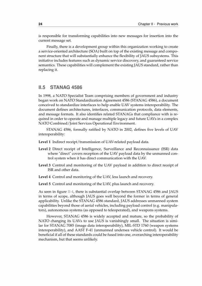
24 Chapter II - Previous work
is responsible for transforming capabilities into new messages for insertion into thecurrent message set.
Finally, there is a development group within this organization working to createa service-oriented architecture (SOA) built on top of the existing message and compo-nent structure that will substantially enhance the flexibility of JAUS subsystems. Thisinitiative includes features such as dynamic service discovery, and guaranteed servicesemantics. These capabilities will complement the existing JAUS standard, rather thanreplacing it.
II.5 STANAG 4586In 1998, a NATO Specialist Team comprising members of government and industrybegan work on NATO Standardization Agreement 4586 (STANAG 4586), a documentconceived to standardize interfaces to help enable UAV systems interoperability. Thedocument defines architectures, interfaces, communication protocols, data elements,and message formats. It also identifies related STANAGs that compliance with is re-quired in order to operate and manage multiple legacy and future UAVs in a complexNATO Combined/Joint Services Operational Environment.
STANAG 4586, formally ratified by NATO in 2002, defines five levels of UAVinteroperability:
Level 1 Indirect receipt/transmission of UAV-related payload data.
Level 2 Direct receipt of Intelligence, Surveillance and Reconnaissance (ISR) datawhere "direct" covers reception of the UAV payload data by the unmanned con-trol system when it has direct communication with the UAV.
Level 3 Control and monitoring of the UAV payload in addition to direct receipt ofISR and other data.
Level 4 Control and monitoring of the UAV, less launch and recovery.
Level 5 Control and monitoring of the UAV, plus launch and recovery.
As seen in figure II-4, there is substantial overlap between STANAG 4586 and JAUSin terms of scope, although JAUS goes well beyond the former in terms of generalapplicability. Unlike the STANAG 4586 standard, JAUS addresses unmanned systemcapabilities beyond those of aerial vehicles, including payload control (e.g. manipula-tors), autonomous systems (as opposed to teleoperated), and weapons systems.
However, STANAG 4586 is widely accepted and mature, so the probability ofNATO changing its UAVs to use JAUS is vanishingly small. The situation is simi-lar for STANAG 7085 (image data interoperability), MIL-STD 1760 (weapon systemsinteroperability), and AAST F-41 (unmanned undersea vehicle control). It would bebeneficial if all of these standards could be fused into one, overarching interoperabilitymechanism, but that seems unlikely.
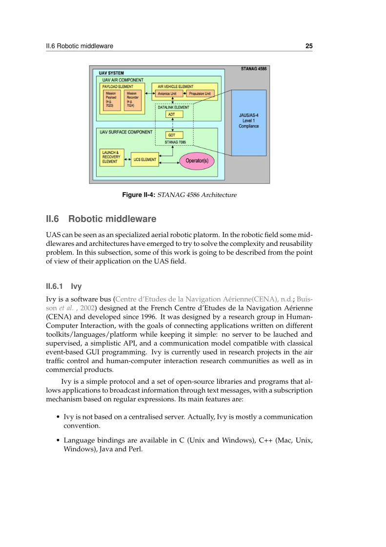
II.6 Robotic middleware 25
Figure II-4: STANAG 4586 Architecture
II.6 Robotic middlewareUAS can be seen as an specialized aerial robotic platorm. In the robotic field some mid-dlewares and architectures have emerged to try to solve the complexity and reusabilityproblem. In this subsection, some of this work is going to be described from the pointof view of their application on the UAS field.
II.6.1 IvyIvy is a software bus (Centre d’Etudes de la Navigation Aérienne(CENA), n.d.; Buis-son et al. , 2002) designed at the French Centre d’Etudes de la Navigation Aérienne(CENA) and developed since 1996. It was designed by a research group in Human-Computer Interaction, with the goals of connecting applications written on differenttoolkits/languages/platform while keeping it simple: no server to be lauched andsupervised, a simplistic API, and a communication model compatible with classicalevent-based GUI programming. Ivy is currently used in research projects in the airtraffic control and human-computer interaction research communities as well as incommercial products.
Ivy is a simple protocol and a set of open-source libraries and programs that al-lows applications to broadcast information through text messages, with a subscriptionmechanism based on regular expressions. Its main features are:
• Ivy is not based on a centralised server. Actually, Ivy is mostly a communicationconvention.
• Language bindings are available in C (Unix and Windows), C++ (Mac, Unix,Windows), Java and Perl.
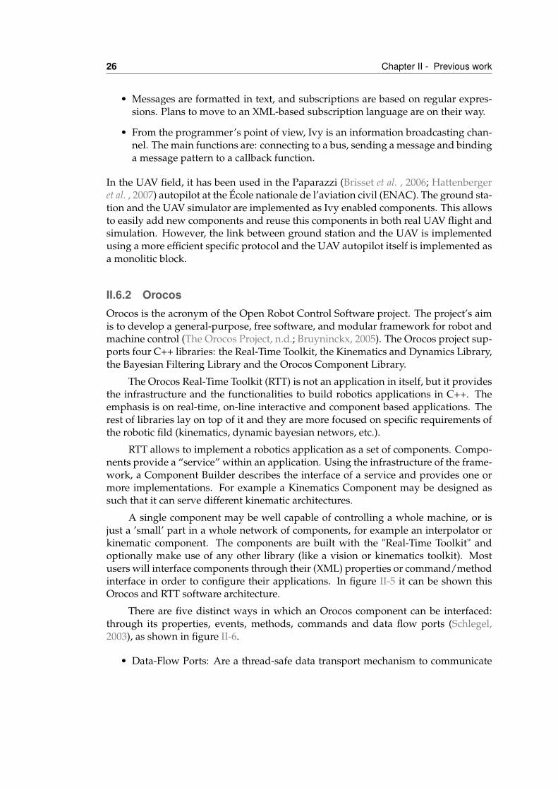
26 Chapter II - Previous work
• Messages are formatted in text, and subscriptions are based on regular expres-sions. Plans to move to an XML-based subscription language are on their way.
• From the programmer’s point of view, Ivy is an information broadcasting chan-nel. The main functions are: connecting to a bus, sending a message and bindinga message pattern to a callback function.
In the UAV field, it has been used in the Paparazzi (Brisset et al. , 2006; Hattenbergeret al. , 2007) autopilot at the École nationale de l’aviation civil (ENAC). The ground sta-tion and the UAV simulator are implemented as Ivy enabled components. This allowsto easily add new components and reuse this components in both real UAV flight andsimulation. However, the link between ground station and the UAV is implementedusing a more efficient specific protocol and the UAV autopilot itself is implemented asa monolitic block.
II.6.2 OrocosOrocos is the acronym of the Open Robot Control Software project. The project’s aimis to develop a general-purpose, free software, and modular framework for robot andmachine control (The Orocos Project, n.d.; Bruyninckx, 2005). The Orocos project sup-ports four C++ libraries: the Real-Time Toolkit, the Kinematics and Dynamics Library,the Bayesian Filtering Library and the Orocos Component Library.
The Orocos Real-Time Toolkit (RTT) is not an application in itself, but it providesthe infrastructure and the functionalities to build robotics applications in C++. Theemphasis is on real-time, on-line interactive and component based applications. Therest of libraries lay on top of it and they are more focused on specific requirements ofthe robotic fild (kinematics, dynamic bayesian networs, etc.).
RTT allows to implement a robotics application as a set of components. Compo-nents provide a “service” within an application. Using the infrastructure of the frame-work, a Component Builder describes the interface of a service and provides one ormore implementations. For example a Kinematics Component may be designed assuch that it can serve different kinematic architectures.
A single component may be well capable of controlling a whole machine, or isjust a ’small’ part in a whole network of components, for example an interpolator orkinematic component. The components are built with the "Real-Time Toolkit" andoptionally make use of any other library (like a vision or kinematics toolkit). Mostusers will interface components through their (XML) properties or command/methodinterface in order to configure their applications. In figure II-5 it can be shown thisOrocos and RTT software architecture.
There are five distinct ways in which an Orocos component can be interfaced:through its properties, events, methods, commands and data flow ports (Schlegel,2003), as shown in figure II-6.
• Data-Flow Ports: Are a thread-safe data transport mechanism to communicate
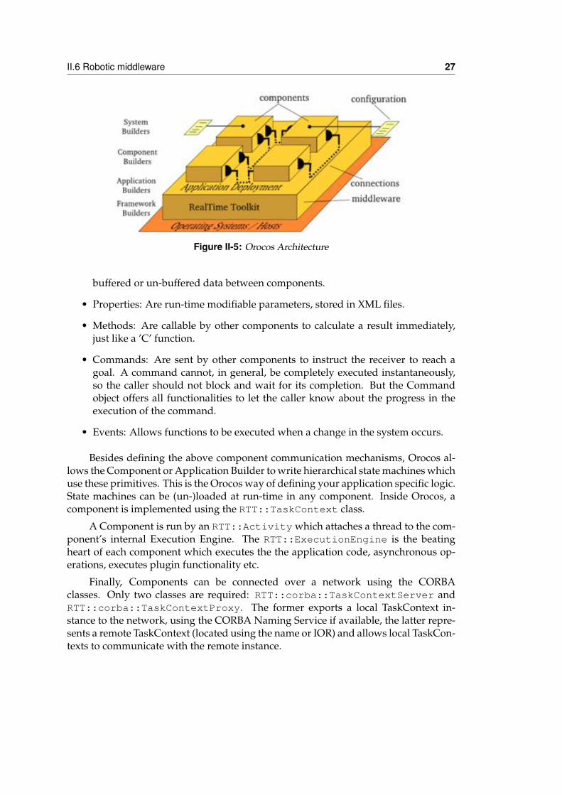
II.6 Robotic middleware 27
Figure II-5: Orocos Architecture
buffered or un-buffered data between components.
• Properties: Are run-time modifiable parameters, stored in XML files.
• Methods: Are callable by other components to calculate a result immediately,just like a ’C’ function.
• Commands: Are sent by other components to instruct the receiver to reach agoal. A command cannot, in general, be completely executed instantaneously,so the caller should not block and wait for its completion. But the Commandobject offers all functionalities to let the caller know about the progress in theexecution of the command.
• Events: Allows functions to be executed when a change in the system occurs.
Besides defining the above component communication mechanisms, Orocos al-lows the Component or Application Builder to write hierarchical state machines whichuse these primitives. This is the Orocos way of defining your application specific logic.State machines can be (un-)loaded at run-time in any component. Inside Orocos, acomponent is implemented using the RTT::TaskContext class.
A Component is run by an RTT::Activity which attaches a thread to the com-ponent’s internal Execution Engine. The RTT::ExecutionEngine is the beatingheart of each component which executes the the application code, asynchronous op-erations, executes plugin functionality etc.
Finally, Components can be connected over a network using the CORBAclasses. Only two classes are required: RTT::corba::TaskContextServer andRTT::corba::TaskContextProxy. The former exports a local TaskContext in-stance to the network, using the CORBA Naming Service if available, the latter repre-sents a remote TaskContext (located using the name or IOR) and allows local TaskCon-texts to communicate with the remote instance.
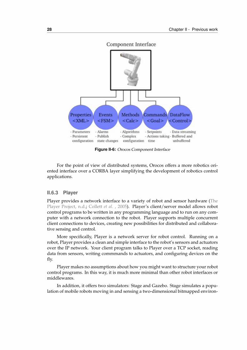
28 Chapter II - Previous work
Figure II-6: Orocos Component Interface
For the point of view of distributed systems, Orocos offers a more robotics ori-ented interface over a CORBA layer simplifying the development of robotics controlapplications.
II.6.3 PlayerPlayer provides a network interface to a variety of robot and sensor hardware (ThePlayer Project, n.d.; Collett et al. , 2005). Player’s client/server model allows robotcontrol programs to be written in any programming language and to run on any com-puter with a network connection to the robot. Player supports multiple concurrentclient connections to devices, creating new possibilities for distributed and collabora-tive sensing and control.
More specifically, Player is a network server for robot control. Running on arobot, Player provides a clean and simple interface to the robot’s sensors and actuatorsover the IP network. Your client program talks to Player over a TCP socket, readingdata from sensors, writing commmands to actuators, and configuring devices on thefly.
Player makes no assumptions about how you might want to structure your robotcontrol programs. In this way, it is much more minimal than other robot interfaces ormiddlewares.
In addition, it offers two simulators: Stage and Gazebo. Stage simulates a popu-lation of mobile robots moving in and sensing a two-dimensional bitmapped environ-
II.7 Conclusions 29
ment (Vaughan, 2008). Gazebo is a multi-robot simulator for outdoor environments.Like Stage, it is capable of simulating a population of robots, sensors and objects, butdoes so in a three-dimensional world. It generates both realistic sensor feedback andphysically plausible interactions between objects.
Both Stage and Gazebo presents a standard Player interface in addition to itsown native interface. They present a standard Player interface so few or no changesare required to move between simulation and hardware. Many controllers designedin the simulators have been demonstrated to work on real robots.
II.7 ConclusionsThis chapter summarizes all the related technologies and research in the field of avion-ics for civil use. This includes avionics buses and architectures and more software ori-ented systems like CORBA or DDS. In the last few years, some initiatives have appearthat are directly focused on the UAS field like JAUS or the NATO STANAG 4586. It isimportant to note that not all the presented works are in the same layer of the ISO/OSInetwork stack.
CORBA is a software standard that started in the enterprise applications area.It assumes a underlying IP network and this way it does not specify all the lowestlevels of the stack. CORBA has been used for some avionics research and also in themilitary field but has some drawbacks, mainly its inherent complexity and locationtransparency, that has limited its usage. Some extensions to CORBA have been de-signed to try to improve its capabilities for embedded systems. Real-time CORBA isfocus on providing end-to-end predictable behaviour and Data Distribution Servicehas added new communication capabilities based on the publish-subscribe paradigm.
On the other hand, avionics buses standarize mainly the lowest part of theISO/OSI stack (physical, data link and network layers). ARINC 429 is probably themost typical aircraft data network. It describes the physical interface and protocol butalso determines the labels that the different equipment has to use to identify the se-mantical value of the data transmitted. Specific equipment for avionics is expensive sonewest developments in avionics buses use commercial off-the-shelf components, likeEthernet, and computer networks standard technologies, like IP. AFDX is the aircraftdata network that is being used in the next generation aircrafts.
But, avionics is not only adopting computer standards but it is also moving froma hardware oriented vision to a software one. In the Integrated Modular Avionics(IMA) approach the avionics functionalities are distributed into software logical parti-tions which may be allocated into a same physical computing module or into a differ-ent one. APEX interface is located between the application software and the operatingsystem. It defines a set of facilities provided by the system for application softwareto control the scheduling, communication, and the status information of its internalprocessing elements.
30 Chapter II - Previous work
Some work is being done standarizing specifically UAS components. Both JAUSand STANAG 4586 are auspicied by the US military. The Joint Architecture for Un-manned Systems (JAUS) is an architecture specifically defined for use in the research,development and acquisition of unmanned systems. This includes several types of un-manned systems or robots not only UAS. JAUS is based on messages which are sentbetween components. Most messages are standarized so interoperability is promoted.In any case, JAUS does not specify the transport mechanism or protocols so it doesnot guarantees interoperability. In addition to this important limitation, JAUS comiteeis currently working in a new service oriented layer to simplify the development ofapplications over it. There is substantial overlap between STANAG 4586 and JAUSin terms of scope, although JAUS goes well beyond the former in terms of generalapplicability. Unlike the JAUS standard, STANAG 4586 mainly addresses interfacesbetween the UAS and the control station.
Finally, UAS are an specialized aerial robotic platorm. In the robotic field somemiddlewares like Ivy, Orocos or Player have emerged to try to solve the problem ofreusability in developing complex robotics applications. Most of them are mostly fo-cused on componentizing local control components while the others offer simple dis-tributed communication among them.
IIISystem Requirements
III.1 Civil Missions for Unmanned Aircraft VehiclesAn Unmanned Aerial Vehicle (UAV) is an aircraft that can fly without a pilot, that is, itis an airframe and a computer system that combines sensors, GPS, servos and CPUs.All these elements combined must pilot the plane without any human intervention.Another usual definition is that of an aircraft that can fly independently, operate in awide range of missions and emergencies, and be controlled from a ground base sta-tion. The UAV’s size, type and configuration can vary and depends on the application.
There is no doubt that a huge market is emerging from the potential applicationsand services that are offered by unmanned aircrafts. More precisely, UAVs can beapplied in “D-cube” missions (UAVNet, n.d.), i.e. missions identified as Dangerous,Dirty or Dull. There are a wide range of civil applications, including remote envi-ronmental research, pollution assessment and monitoring, fire fighting management,security e.g. border monitoring, agricultural and fishery applications, oceanographyand communication relays for wideband applications. In general, we can divide all ofthese applications into four main groups of applications: environmental, emergency-security, communication and monitoring. These four groups are depicted in Figure
31
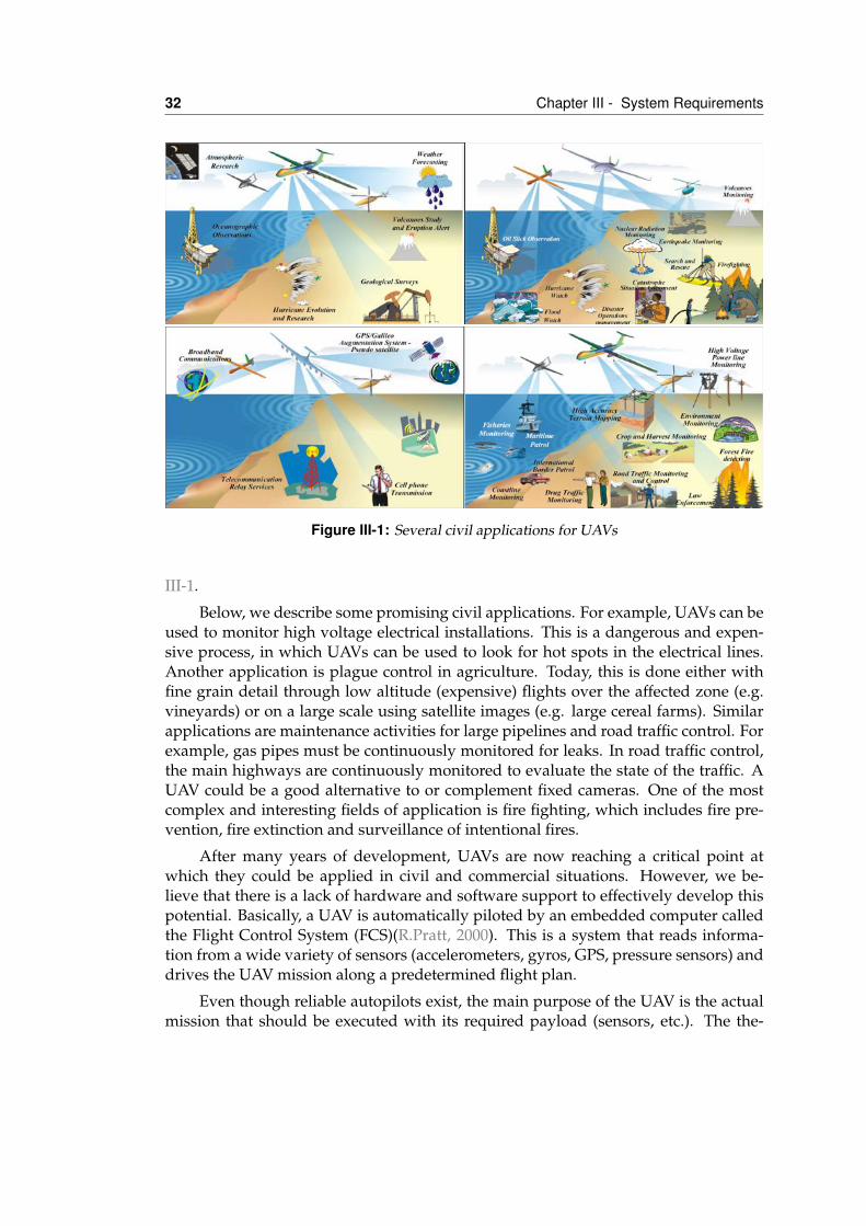
32 Chapter III - System Requirements
Figure III-1: Several civil applications for UAVs
III-1.
Below, we describe some promising civil applications. For example, UAVs can beused to monitor high voltage electrical installations. This is a dangerous and expen-sive process, in which UAVs can be used to look for hot spots in the electrical lines.Another application is plague control in agriculture. Today, this is done either withfine grain detail through low altitude (expensive) flights over the affected zone (e.g.vineyards) or on a large scale using satellite images (e.g. large cereal farms). Similarapplications are maintenance activities for large pipelines and road traffic control. Forexample, gas pipes must be continuously monitored for leaks. In road traffic control,the main highways are continuously monitored to evaluate the state of the traffic. AUAV could be a good alternative to or complement fixed cameras. One of the mostcomplex and interesting fields of application is fire fighting, which includes fire pre-vention, fire extinction and surveillance of intentional fires.
After many years of development, UAVs are now reaching a critical point atwhich they could be applied in civil and commercial situations. However, we be-lieve that there is a lack of hardware and software support to effectively develop thispotential. Basically, a UAV is automatically piloted by an embedded computer calledthe Flight Control System (FCS)(R.Pratt, 2000). This is a system that reads informa-tion from a wide variety of sensors (accelerometers, gyros, GPS, pressure sensors) anddrives the UAV mission along a predetermined flight plan.
Even though reliable autopilots exist, the main purpose of the UAV is the actualmission that should be executed with its required payload (sensors, etc.). The the-
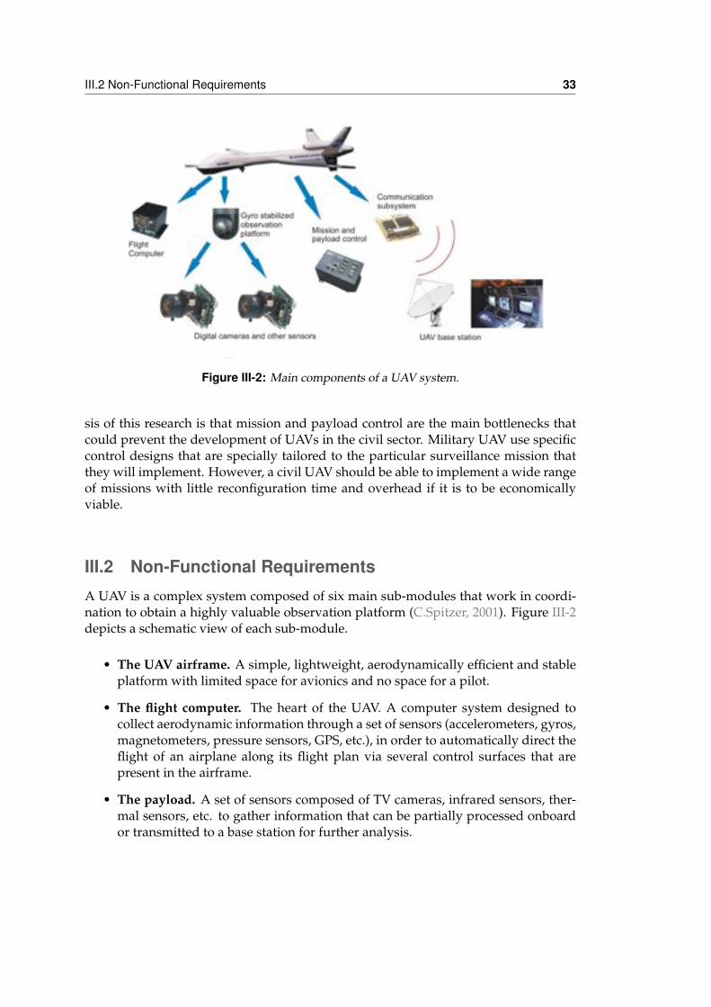
III.2 Non-Functional Requirements 33
Figure III-2: Main components of a UAV system.
sis of this research is that mission and payload control are the main bottlenecks thatcould prevent the development of UAVs in the civil sector. Military UAV use specificcontrol designs that are specially tailored to the particular surveillance mission thatthey will implement. However, a civil UAV should be able to implement a wide rangeof missions with little reconfiguration time and overhead if it is to be economicallyviable.
III.2 Non-Functional RequirementsA UAV is a complex system composed of six main sub-modules that work in coordi-nation to obtain a highly valuable observation platform (C.Spitzer, 2001). Figure III-2depicts a schematic view of each sub-module.
• The UAV airframe. A simple, lightweight, aerodynamically efficient and stableplatform with limited space for avionics and no space for a pilot.
• The flight computer. The heart of the UAV. A computer system designed tocollect aerodynamic information through a set of sensors (accelerometers, gyros,magnetometers, pressure sensors, GPS, etc.), in order to automatically direct theflight of an airplane along its flight plan via several control surfaces that arepresent in the airframe.
• The payload. A set of sensors composed of TV cameras, infrared sensors, ther-mal sensors, etc. to gather information that can be partially processed onboardor transmitted to a base station for further analysis.
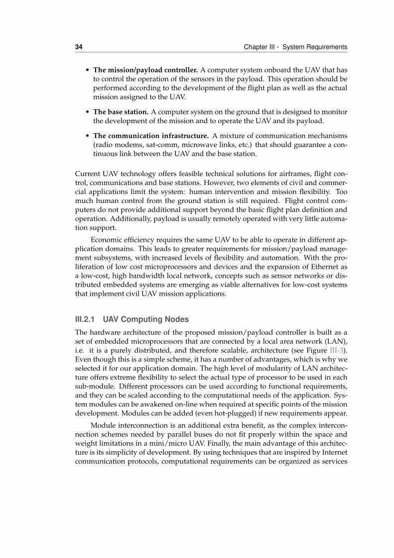
34 Chapter III - System Requirements
• The mission/payload controller. A computer system onboard the UAV that hasto control the operation of the sensors in the payload. This operation should beperformed according to the development of the flight plan as well as the actualmission assigned to the UAV.
• The base station. A computer system on the ground that is designed to monitorthe development of the mission and to operate the UAV and its payload.
• The communication infrastructure. A mixture of communication mechanisms(radio modems, sat-comm, microwave links, etc.) that should guarantee a con-tinuous link between the UAV and the base station.
Current UAV technology offers feasible technical solutions for airframes, flight con-trol, communications and base stations. However, two elements of civil and commer-cial applications limit the system: human intervention and mission flexibility. Toomuch human control from the ground station is still required. Flight control com-puters do not provide additional support beyond the basic flight plan definition andoperation. Additionally, payload is usually remotely operated with very little automa-tion support.
Economic efficiency requires the same UAV to be able to operate in different ap-plication domains. This leads to greater requirements for mission/payload manage-ment subsystems, with increased levels of flexibility and automation. With the pro-liferation of low cost microprocessors and devices and the expansion of Ethernet asa low-cost, high bandwidth local network, concepts such as sensor networks or dis-tributed embedded systems are emerging as viable alternatives for low-cost systemsthat implement civil UAV mission applications.
III.2.1 UAV Computing NodesThe hardware architecture of the proposed mission/payload controller is built as aset of embedded microprocessors that are connected by a local area network (LAN),i.e. it is a purely distributed, and therefore scalable, architecture (see Figure III-3).Even though this is a simple scheme, it has a number of advantages, which is why weselected it for our application domain. The high level of modularity of LAN architec-ture offers extreme flexibility to select the actual type of processor to be used in eachsub-module. Different processors can be used according to functional requirements,and they can be scaled according to the computational needs of the application. Sys-tem modules can be awakened on-line when required at specific points of the missiondevelopment. Modules can be added (even hot-plugged) if new requirements appear.
Module interconnection is an additional extra benefit, as the complex intercon-nection schemes needed by parallel buses do not fit properly within the space andweight limitations in a mini/micro UAV. Finally, the main advantage of this architec-ture is its simplicity of development. By using techniques that are inspired by Internetcommunication protocols, computational requirements can be organized as services
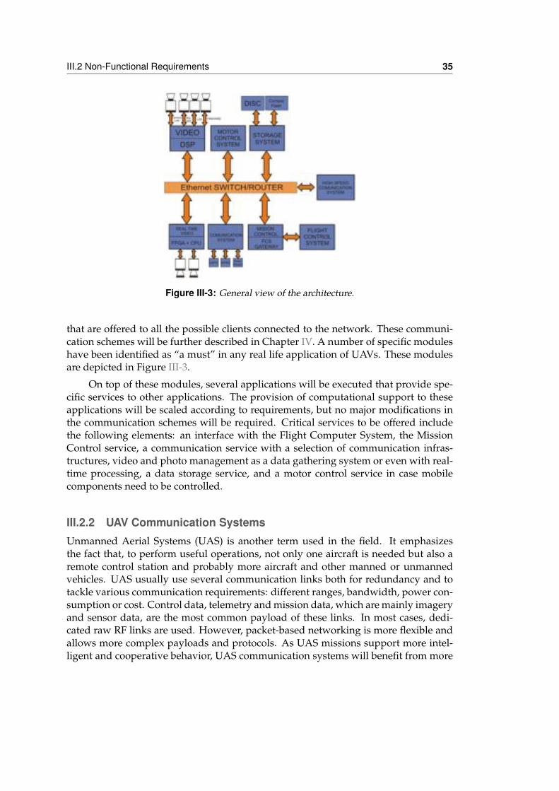
III.2 Non-Functional Requirements 35
Figure III-3: General view of the architecture.
that are offered to all the possible clients connected to the network. These communi-cation schemes will be further described in Chapter IV. A number of specific moduleshave been identified as “a must” in any real life application of UAVs. These modulesare depicted in Figure III-3.
On top of these modules, several applications will be executed that provide spe-cific services to other applications. The provision of computational support to theseapplications will be scaled according to requirements, but no major modifications inthe communication schemes will be required. Critical services to be offered includethe following elements: an interface with the Flight Computer System, the MissionControl service, a communication service with a selection of communication infras-tructures, video and photo management as a data gathering system or even with real-time processing, a data storage service, and a motor control service in case mobilecomponents need to be controlled.
III.2.2 UAV Communication SystemsUnmanned Aerial Systems (UAS) is another term used in the field. It emphasizesthe fact that, to perform useful operations, not only one aircraft is needed but also aremote control station and probably more aircraft and other manned or unmannedvehicles. UAS usually use several communication links both for redundancy and totackle various communication requirements: different ranges, bandwidth, power con-sumption or cost. Control data, telemetry and mission data, which are mainly imageryand sensor data, are the most common payload of these links. In most cases, dedi-cated raw RF links are used. However, packet-based networking is more flexible andallows more complex payloads and protocols. As UAS missions support more intel-ligent and cooperative behavior, UAS communication systems will benefit from more
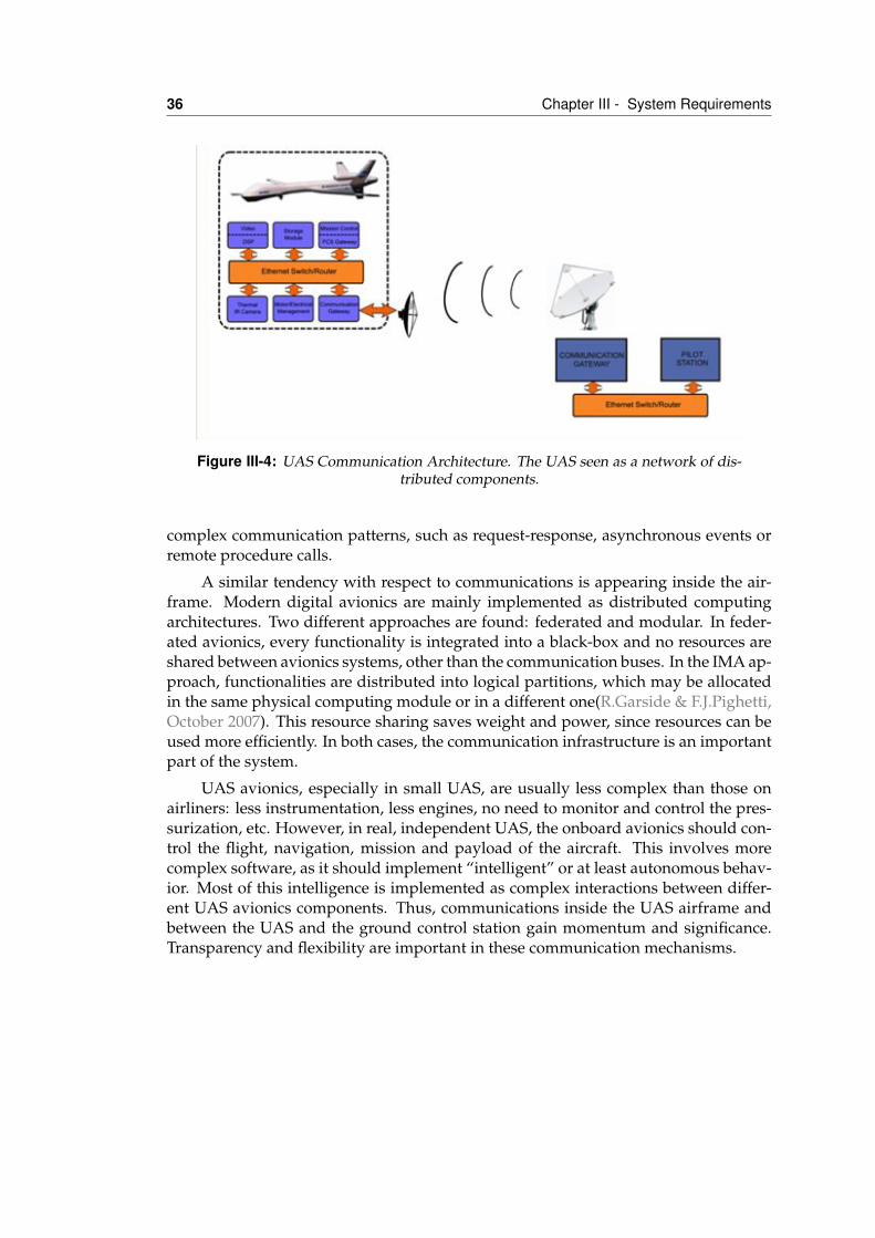
36 Chapter III - System Requirements
Figure III-4: UAS Communication Architecture. The UAS seen as a network of dis-tributed components.
complex communication patterns, such as request-response, asynchronous events orremote procedure calls.
A similar tendency with respect to communications is appearing inside the air-frame. Modern digital avionics are mainly implemented as distributed computingarchitectures. Two different approaches are found: federated and modular. In feder-ated avionics, every functionality is integrated into a black-box and no resources areshared between avionics systems, other than the communication buses. In the IMA ap-proach, functionalities are distributed into logical partitions, which may be allocatedin the same physical computing module or in a different one(R.Garside & F.J.Pighetti,October 2007). This resource sharing saves weight and power, since resources can beused more efficiently. In both cases, the communication infrastructure is an importantpart of the system.
UAS avionics, especially in small UAS, are usually less complex than those onairliners: less instrumentation, less engines, no need to monitor and control the pres-surization, etc. However, in real, independent UAS, the onboard avionics should con-trol the flight, navigation, mission and payload of the aircraft. This involves morecomplex software, as it should implement “intelligent” or at least autonomous behav-ior. Most of this intelligence is implemented as complex interactions between differ-ent UAS avionics components. Thus, communications inside the UAS airframe andbetween the UAS and the ground control station gain momentum and significance.Transparency and flexibility are important in these communication mechanisms.
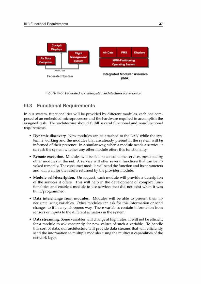
III.3 Functional Requirements 37
Figure III-5: Federated and integrated architectures for avionics.
III.3 Functional RequirementsIn our system, functionalities will be provided by different modules, each one com-posed of an embedded microprocessor and the hardware required to accomplish theassigned task. The architecture should fulfill several functional and non-functionalrequirements.
• Dynamic discovery. New modules can be attached to the LAN while the sys-tem is working and the modules that are already present in the system will beinformed of their presence. In a similar way, when a module needs a service, itcan ask the system whether any other module offers this functionality.
• Remote execution. Modules will be able to consume the services presented byother modules in the net. A service will offer several functions that can be in-voked remotely. The consumer module will send the function and its parametersand will wait for the results returned by the provider module.
• Module self-description. On request, each module will provide a descriptionof the services it offers. This will help in the development of complex func-tionalities and enable a module to use services that did not exist when it wasbuilt/programmed.
• Data interchange from modules. Modules will be able to present their in-ner state using variables. Other modules can ask for this information or sendchanges to it in a synchronous way. These variables contain information fromsensors or inputs to the different actuators in the system.
• Data streaming. Some variables will change at high rates. It will not be efficientfor a module to ask constantly for new values of such a variable. To handlethis sort of data, our architecture will provide data streams that will efficientlysend the information to multiple modules using the multicast capabilities of thenetwork layer.
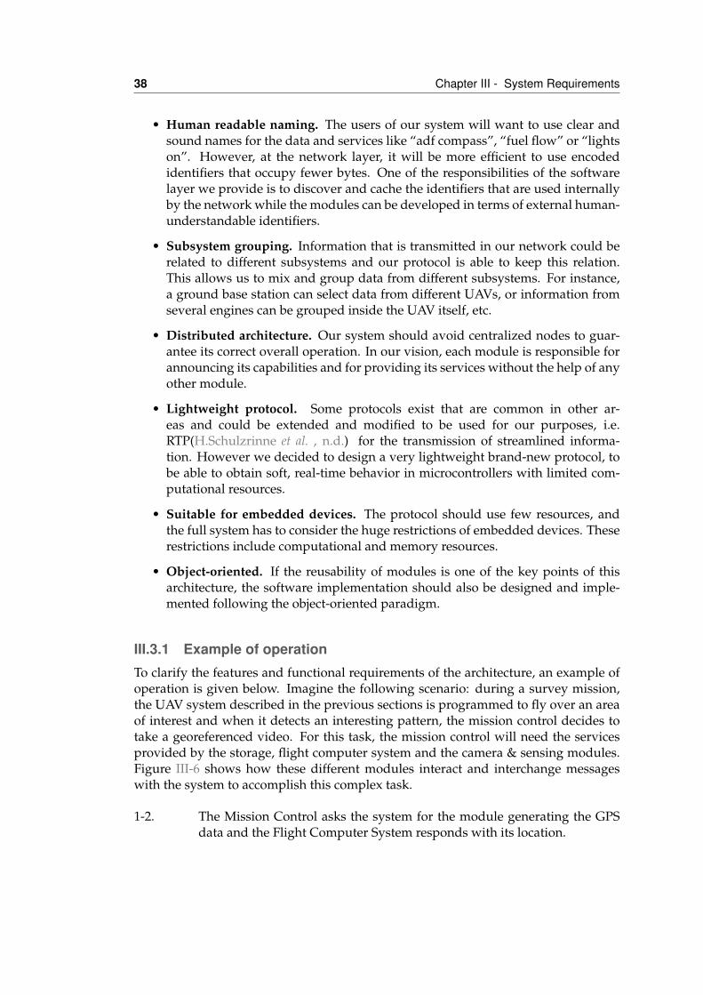
38 Chapter III - System Requirements
• Human readable naming. The users of our system will want to use clear andsound names for the data and services like “adf compass”, “fuel flow” or “lightson”. However, at the network layer, it will be more efficient to use encodedidentifiers that occupy fewer bytes. One of the responsibilities of the softwarelayer we provide is to discover and cache the identifiers that are used internallyby the network while the modules can be developed in terms of external human-understandable identifiers.
• Subsystem grouping. Information that is transmitted in our network could berelated to different subsystems and our protocol is able to keep this relation.This allows us to mix and group data from different subsystems. For instance,a ground base station can select data from different UAVs, or information fromseveral engines can be grouped inside the UAV itself, etc.
• Distributed architecture. Our system should avoid centralized nodes to guar-antee its correct overall operation. In our vision, each module is responsible forannouncing its capabilities and for providing its services without the help of anyother module.
• Lightweight protocol. Some protocols exist that are common in other ar-eas and could be extended and modified to be used for our purposes, i.e.RTP(H.Schulzrinne et al. , n.d.) for the transmission of streamlined informa-tion. However we decided to design a very lightweight brand-new protocol, tobe able to obtain soft, real-time behavior in microcontrollers with limited com-putational resources.
• Suitable for embedded devices. The protocol should use few resources, andthe full system has to consider the huge restrictions of embedded devices. Theserestrictions include computational and memory resources.
• Object-oriented. If the reusability of modules is one of the key points of thisarchitecture, the software implementation should also be designed and imple-mented following the object-oriented paradigm.
III.3.1 Example of operationTo clarify the features and functional requirements of the architecture, an example ofoperation is given below. Imagine the following scenario: during a survey mission,the UAV system described in the previous sections is programmed to fly over an areaof interest and when it detects an interesting pattern, the mission control decides totake a georeferenced video. For this task, the mission control will need the servicesprovided by the storage, flight computer system and the camera & sensing modules.Figure III-6 shows how these different modules interact and interchange messageswith the system to accomplish this complex task.
1-2. The Mission Control asks the system for the module generating the GPSdata and the Flight Computer System responds with its location.
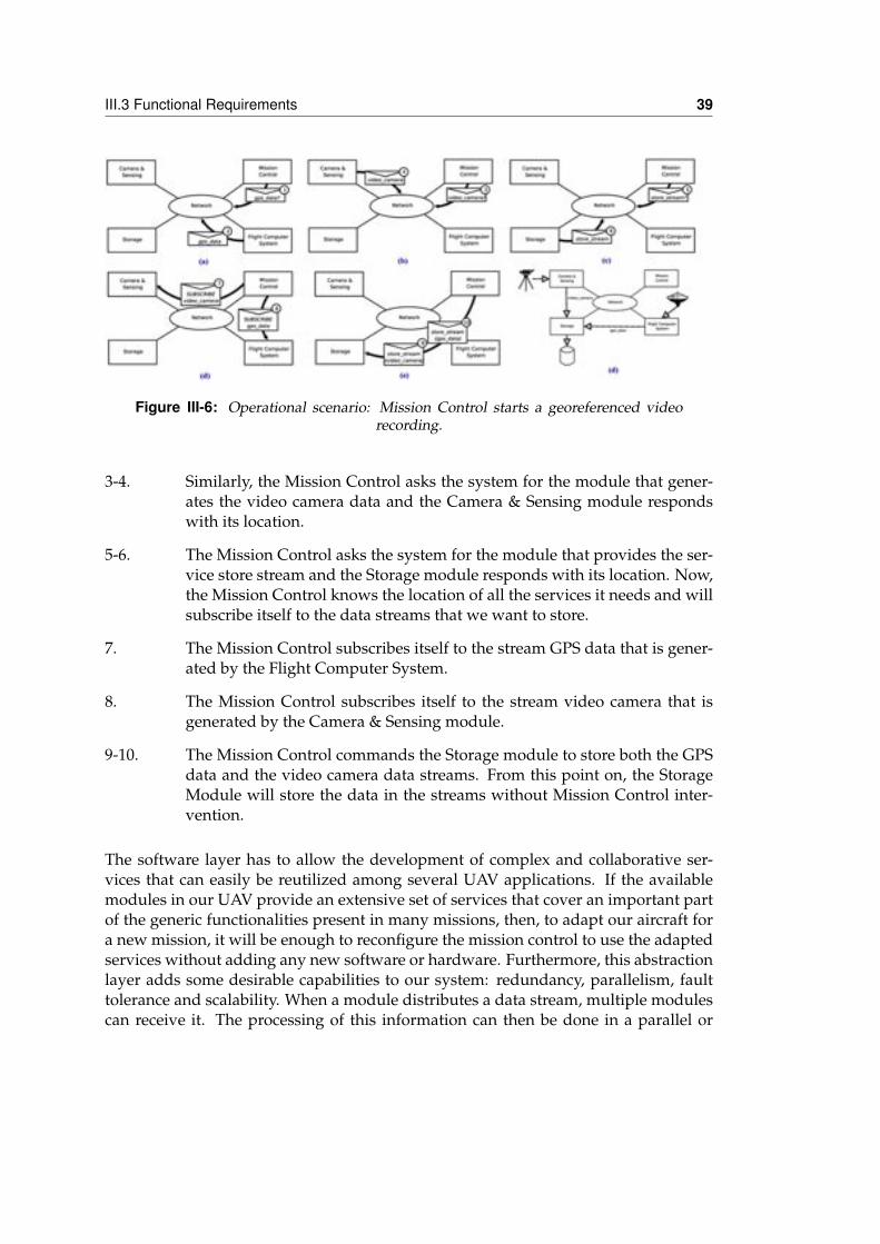
III.3 Functional Requirements 39
Figure III-6: Operational scenario: Mission Control starts a georeferenced videorecording.
3-4. Similarly, the Mission Control asks the system for the module that gener-ates the video camera data and the Camera & Sensing module respondswith its location.
5-6. The Mission Control asks the system for the module that provides the ser-vice store stream and the Storage module responds with its location. Now,the Mission Control knows the location of all the services it needs and willsubscribe itself to the data streams that we want to store.
7. The Mission Control subscribes itself to the stream GPS data that is gener-ated by the Flight Computer System.
8. The Mission Control subscribes itself to the stream video camera that isgenerated by the Camera & Sensing module.
9-10. The Mission Control commands the Storage module to store both the GPSdata and the video camera data streams. From this point on, the StorageModule will store the data in the streams without Mission Control inter-vention.
The software layer has to allow the development of complex and collaborative ser-vices that can easily be reutilized among several UAV applications. If the availablemodules in our UAV provide an extensive set of services that cover an important partof the generic functionalities present in many missions, then, to adapt our aircraft fora new mission, it will be enough to reconfigure the mission control to use the adaptedservices without adding any new software or hardware. Furthermore, this abstractionlayer adds some desirable capabilities to our system: redundancy, parallelism, faulttolerance and scalability. When a module distributes a data stream, multiple modulescan receive it. The processing of this information can then be done in a parallel or
40 Chapter III - System Requirements
redundant way, for example by processing alternate video frames in two modules orby storing two copies of the sensor data in two different storage modules.
In an analogous way, different modules can offer the same services. When a mod-ule asks the system for a particular action, it does not know exactly (and it does notneed to know) which node is going to respond. Thus, in the case of module failure,another module with equivalent functionalities can meet its responsibilities transpar-ently. This architecture also allows an important degree of scalability and flexibility,as there is no need for advance knowledge of which hardware nodes are the servicesthat are mapped. A hardware node can initially offer several services, and if low per-formance is detected, the services can be distributed among several nodes. The appli-cations that implement the mission operative will be unaware of this sort of changes.
III.4 ConclusionsWhile the architecture designed in this thesis should be applicable to multiple embed-ded applications, the focus application is the avionics of unmanned aircraft. In thischapter, we have defined unmanned aircraft vehicle concepts and described their civilapplications. The current state of the art leads us to modularize the UAV components:this has happened in airliner and military avionics and will happen in the unmannedvehicles field as they become more common and their capabilities and requirementsincrease in complexity.
Our proposed architecture for mission and payload control is designed as a setof reusable modules around a local area network. This interconnecting pattern is flex-ible and inexpensive. It can be used in this scenario and in other embedded, complexsystems. A set of system requirements has been extracted to improve the current char-acteristics of UAV mission control systems. Finally, an example of operation has beendescribed to show the basic functioning and to guide the next steps in the develop-ment of the architecture.
IVService-Oriented Architecture
IV.1 IntroductionService-oriented architectures (SOA) are becoming common in several domains, forexample web services(World Wide Web Consortium, n.d.) in the Internet world andUPnP(UPNP Consortium, n.d.) in the home automation area. SOA is an architecturalstyle whose goal is to achieve loose coupling among interacting components or ser-vices. A service is a unit of work performed by a service provider to achieve desiredend results for a service consumer. Both provider and consumer are roles played bysoftware agents on behalf of their owners. The results of a service are usually a changeof state for the consumer, but they may also be a change of state for the provider or forboth parties.
The Organization for the Advancement of Structured Information Standards(OASIS) defines SOA as the following: a paradigm for organizing and utilizingdistributed capabilities that may be under the control of different ownership do-mains. It provides a uniform means to offer, discover, interact with and use capa-bilities to produce desired effects consistent with measurable preconditions and ex-pectations(OASIS (Organization for the Advancement of Structured Information Stan-
41
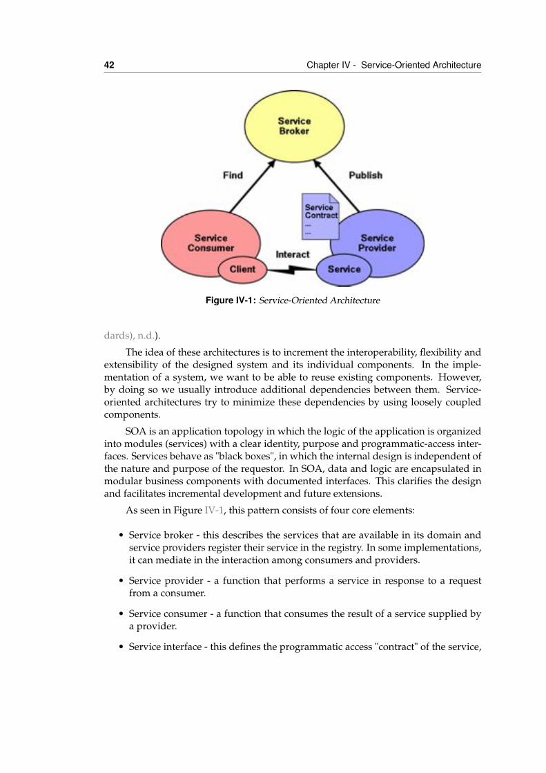
42 Chapter IV - Service-Oriented Architecture
Figure IV-1: Service-Oriented Architecture
dards), n.d.).
The idea of these architectures is to increment the interoperability, flexibility andextensibility of the designed system and its individual components. In the imple-mentation of a system, we want to be able to reuse existing components. However,by doing so we usually introduce additional dependencies between them. Service-oriented architectures try to minimize these dependencies by using loosely coupledcomponents.
SOA is an application topology in which the logic of the application is organizedinto modules (services) with a clear identity, purpose and programmatic-access inter-faces. Services behave as "black boxes", in which the internal design is independent ofthe nature and purpose of the requestor. In SOA, data and logic are encapsulated inmodular business components with documented interfaces. This clarifies the designand facilitates incremental development and future extensions.
As seen in Figure IV-1, this pattern consists of four core elements:
• Service broker - this describes the services that are available in its domain andservice providers register their service in the registry. In some implementations,it can mediate in the interaction among consumers and providers.
• Service provider - a function that performs a service in response to a requestfrom a consumer.
• Service consumer - a function that consumes the result of a service supplied bya provider.
• Service interface - this defines the programmatic access "contract" of the service,
IV.2 Service definition 43
establishes the service identity and the rules of the service invocation.
The relationship between a service provider and consumer is dynamic and establishedat runtime by a binding mechanism. This dynamic binding minimizes the dependen-cies between the service consumer and service provider. SOA achieves loose couplingamong interacting components by employing two architectural constraints. First, allthe participant components share the same small set of simple and ubiquitous inter-faces, with only generic semantics encoded in them. Second, each interface can pro-vide on request descriptive messages that explain its operation and capabilities. Thesemessages define the structure and semantics of the services provided. The constraintsare inspired significantly by object-oriented programming, which strongly suggeststhat you should bind data and its processing together.
In our network-centric vision, when a component needs a functionality that itdoes not provide, it asks the network for the required service. If another componentof the system has this capability, the middleware will discover its location and theclient component will be able to consume the service using the common interface ofthe provider component. The interface of an SOA component must be simple andclear enough to be easily implemented in different hardware and software platforms.To simplify the development of services, a small software layer, the middleware, isused.
SOA is an architectural style in which several designs and implementations arepossible. In this chapter, we will describe our service vision, the interface, and thecommunication mechanisms available to communicate among them. Middleware Ar-chitecture for Remote Embedded Applications (Marea) is the name of the definedservice-oriented architecture.
IV.2 Service definitionOver a network of computational nodes, we deploy the different services that willimplement the UAS avionics functionalities. A service is a software application thatbehaves as a producer of data and/or as a consumer of data from other services thatare present in the system. Figure IV-3 shows several examples of services as blackboxes that are executed on top of the Marea middleware.
A Marea communication primitive identifies exchanged data rather thanproviders or consumers. This functioning principle is similar to that of existing avion-ics buses, such as ARINC 429. This bus broadcasts transmitted data with extra in-formation (label) to all the linked equipment that has recognized the label use data.Hence, like ARINC 429 (ARINC, n.d.a) or APEX ports (ARINC, n.d.c), Marea linksproducers and receivers of data, without a priori knowledge of their physical loca-tion. In contrast to ARINC APEX, we do not define partitions as the main focus ofour system is ease of reconfiguration. Of course, a physical partition is given by thehardware nodes and in Chapter VI we will explain how services are allocated to nodes
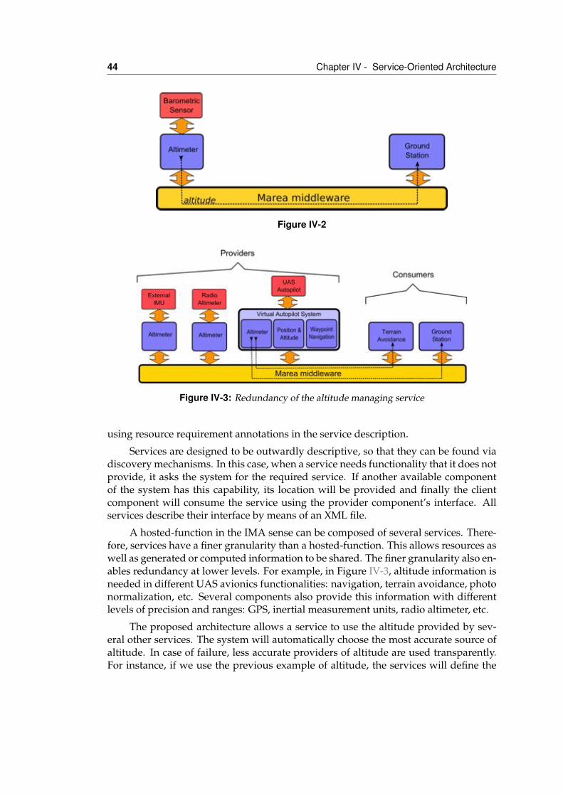
44 Chapter IV - Service-Oriented Architecture
Figure IV-2
Figure IV-3: Redundancy of the altitude managing service
using resource requirement annotations in the service description.
Services are designed to be outwardly descriptive, so that they can be found viadiscovery mechanisms. In this case, when a service needs functionality that it does notprovide, it asks the system for the required service. If another available componentof the system has this capability, its location will be provided and finally the clientcomponent will consume the service using the provider component’s interface. Allservices describe their interface by means of an XML file.
A hosted-function in the IMA sense can be composed of several services. There-fore, services have a finer granularity than a hosted-function. This allows resources aswell as generated or computed information to be shared. The finer granularity also en-ables redundancy at lower levels. For example, in Figure IV-3, altitude information isneeded in different UAS avionics functionalities: navigation, terrain avoidance, photonormalization, etc. Several components also provide this information with differentlevels of precision and ranges: GPS, inertial measurement units, radio altimeter, etc.
The proposed architecture allows a service to use the altitude provided by sev-eral other services. The system will automatically choose the most accurate source ofaltitude. In case of failure, less accurate providers of altitude are used transparently.For instance, if we use the previous example of altitude, the services will define the
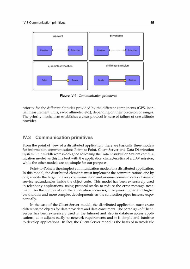
IV.3 Communication primitives 45
Figure IV-4: Communication primitives
priority for the different altitudes provided by the different components (GPS, iner-tial measurement units, radio altimeter, etc.), depending on their precision or ranges.The priority mechanism establishes a clear protocol in case of failure of one altitudeprovider.
IV.3 Communication primitivesFrom the point of view of a distributed application, there are basically three modelsfor information communication: Point-to-Point, Client-Server and Data DistributionSystem. Our middleware is designed following the Data Distribution System commu-nication model, as this fits best with the application characteristics of a UAV mission,while the other models are too simple for our purposes.
Point-to-Point is the simplest communication model for a distributed application.In this model, the distributed elements must implement the communications one byone, specify the target of every communication and assume communication losses orservice redundancies inside the object code. This model has been extensively usedin telephony applications, using protocol stacks to reduce the error message treat-ment. As the complexity of the application increases, it requires higher and higherbandwidths and more complex developments, as the connection pipes increase expo-nentially.
In the case of the Client-Server model, the distributed application must createdifferentiated objects for data providers and data consumers. The paradigm of Client-Server has been extensively used in the Internet and also in database access appli-cations, as it adjusts easily to network requirements and it is simple and intuitiveto develop applications. In fact, the Client-Server model is the basis of network file
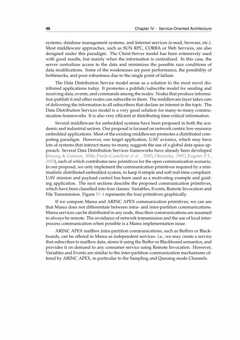
46 Chapter IV - Service-Oriented Architecture
systems, database management systems, and Internet services (e-mail, browser, etc.).Most middleware approaches, such as SUN RPC, CORBA or Web Services, are alsodesigned under this paradigm. The Client-Server model has been extensively usedwith good results, but mainly when the information is centralized. In this case, theserver centralizes access to the data and minimizes the possible race conditions ofdata modifications. Some of the weaknesses are poor performance, the possibility ofbottlenecks, and poor robustness due to the single point of failure.
The Data Distribution Service model arose as a solution to the most novel dis-tributed applications today. It promotes a publish/subscribe model for sending andreceiving data, events, and commands among the nodes. Nodes that produce informa-tion publish it and other nodes can subscribe to them. The middleware layer takes careof delivering the information to all subscribers that declare an interest in the topic. TheData Distribution Services model is a very good solution for many-to-many commu-nication frameworks. It is also very efficient at distributing time-critical information.
Several middleware for embedded systems have been proposed in both the aca-demic and industrial sectors. Our proposal is focused on network centric low-resourceembedded applications. Most of the existing middleware promotes a distributed com-puting paradigm. However, our target application, UAV avionics, which may havelots of systems that interact many-to-many, suggests the use of a global data space ap-proach. Several Data Distribution Services frameworks have already been developed(Huang & Gannon, 2006; Pardo-Castellote et al. , 2005; Obraczka, 1997; Eugster P.T.,2003), each of which contributes new primitives for the open communication scenario.In our proposal, we only implement the communication primitives required by a min-imalistic distributed embedded system, to keep it simple and soft real-time compliant.UAV mission and payload control has been used as a motivating example and guid-ing application. The next sections describe the proposed communication primitives,which have been classified into four classes: Variables, Events, Remote Invocation andFile Transmission. Figure IV-4 represents the four primitives graphically.
If we compare Marea and ARINC APEX communication primitives, we can seethat Marea does not differentiate between intra- and inter-partition communications.Marea services can be distributed in any node, thus their communications are assumedto always be remote. The avoidance of network transmission and the use of local inter-process communication when possible is a Marea implementation issue.
ARINC APEX mailbox intra-partition communications, such as Buffers or Black-boards, can be offered in Marea as independent services. i.e., we may create a servicethat subscribes to mailbox data, stores it using the Buffer or Blackboard semantics, andprovides it on demand to any consumer service using Remote Invocation. However,Variables and Events are similar to the inter-partition communication mechanisms of-fered by ARINC APEX, in particular to the Sampling and Queuing mode Channels.
IV.3 Communication primitives 47
IV.3.1 VariablesBy variables, we mean the transmission of structured, and generally short, informa-tion from a service to one or more additional services in the distributed system. Thisinformation is sent at regular intervals or each time a substantial change in its valueoccurs. The relative caducity of the information means that it can be sent in a best-effort way. The system should be able to tolerate the loss of one or more of these datatransmissions. This communication primitive follows the publication-subscriptionparadigm.
A service can provide zero or more variables. Each of them is composed of a basictype (boolean, integer, floating point real, character string, etc.) or by a composition(vector, struct or union) of basic types. From the point of view of the allowed datatypes in a variable, our middleware is similar to a C-like language.
A service announces the availability of its variables by means of the middlewarelayer. This way, other services that are present in the distributed embedded systemcan subscribe to one or more of these variables. From the moment a service subscribesto a variable, the provider service is responsible for sending it with the agreed qualityof service characteristics. In any case, services that use this communication primitiveshould tolerate the loss of some variable values. If this situation continues, the servicecontainer will warn the affected services of this timeout circumstance.
The provider service can specify the variable validity as a quality of service pa-rameter. When a variable value is lost, the subscribed services can receive previousvalues, as long as they are still valid. In addition, the middleware has a mechanismthat guarantees an initial valid value for the services that need it.
The service container maps this sort of communication over UDP packets inbroadcast or multicast mode, when this is allowed by the underlying network. Thissort of transmission allows the optimization of bandwidth use, as one packet that issent can reach multiple nodes in the distributed embedded system.
IV.3.2 EventsEvents are similar to variables in the sense that both work according to the publication-subscription paradigm. The main difference is that events, as opposed to variables,guarantee the reception of the sent information to all of the subscribed services. Theutility of events is to provide punctual and important facts to all the services that re-quire this information. Some examples can be error alarms or warnings, indication ofarrival at specific points of the mission, start of some pre-programmed actions, suchas taking a photo, etc. Events can contain associated information (error codes, currentposition, etc.) or have a meaning in themselves. When they carry additional informa-tion, data is coded the same way as in the variable communication primitive.
An important fact that has to be taken into account in events, apart from thecorrect reception of the message by all subscribers, is that latency due to reception andprocessing may be critical. A typical solution to this problem is the reservation of time
48 Chapter IV - Service-Oriented Architecture
slots in both the processor and the network.
The publisher and subscriber services interact with other services and always usethe service container, as in the variable case. Finally, this communication primitiveis mapped by the service container over TCP or over UDP, using a mechanism thatacknowledges and resends lost packets. This specific retransmission mechanism in theapplication layer is more efficient for event messages than the generic case providedby the TCP stack.
IV.3.3 Remote invocationMost middleware implements some form of distributed computing, based on the re-mote procedure call paradigm, for example ONC RPC, CORBA or Web Services. How-ever, for some distributed embedded domains, the data publication-subscription orglobal data space paradigm seem more appropriate. Therefore, we provide a first-class set of publish-subscribe communication primitives.
Nevertheless, remote invocation is an intuitive way of modeling some sort ofinteractions between services. Some examples can be the activation and deactivationof actuators, or calling a service for some form of calculation. Thus, in addition tovariables and events, services can present a set of functions that other services caninvoke or call remotely. The functions that are presented by a service can have anarbitrary number of parameters and optionally a return value.
This communication primitive implements two-way point-to-point communica-tion between two services: one acts as a client and the other as server. The clientservice is always the initiator or the communication and the server service location isabstracted by the middleware. However, one of the differences from previous com-munication primitives is that the client service is not continuously subscribed or con-nected to the server service. Their relation is occasional and delimited by the time theinvocation is executed.
During middleware initialization, the services can check that all the functionsthey need to properly accomplish their task are provided by one or more services inthe network. Redundancy and fault-tolerance are managed by the middleware, whichcan also redirect remote calls to server services statically or dynamically. Static alloca-tions of the client-server relationships are useful in critical services in which resourcessuch as CPU time or network bandwidth are pre-allocated. On the other hand, run-time information can be used to redirect calls for non-critical services to the serverwhere the best performance is expected. To achieve this, load balancing techniquesare used.
On service failure, if another service implements the same functionality, the mid-dleware will detect the situation and redirect requests to the redundant service. Thisallows the system to continue its mission, although perhaps in a degraded mode. Ifno service provides the requested function, the middleware will warn the system totake the programmed emergency procedure.
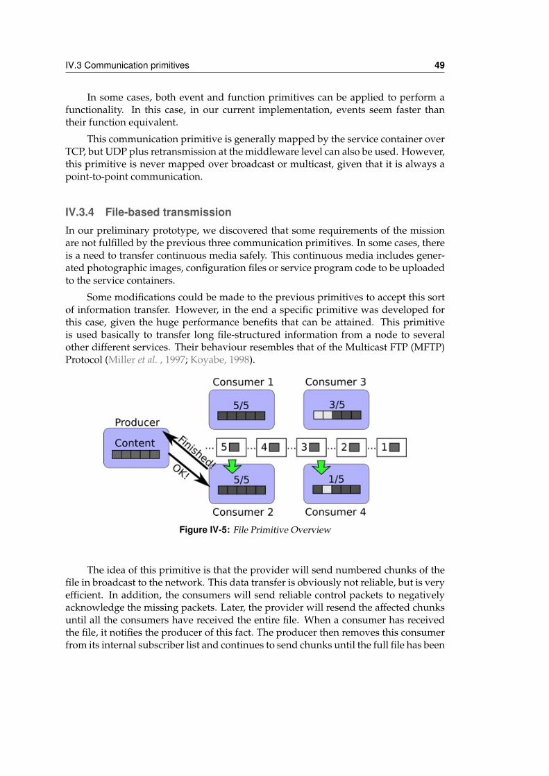
IV.3 Communication primitives 49
In some cases, both event and function primitives can be applied to perform afunctionality. In this case, in our current implementation, events seem faster thantheir function equivalent.
This communication primitive is generally mapped by the service container overTCP, but UDP plus retransmission at the middleware level can also be used. However,this primitive is never mapped over broadcast or multicast, given that it is always apoint-to-point communication.
IV.3.4 File-based transmissionIn our preliminary prototype, we discovered that some requirements of the missionare not fulfilled by the previous three communication primitives. In some cases, thereis a need to transfer continuous media safely. This continuous media includes gener-ated photographic images, configuration files or service program code to be uploadedto the service containers.
Some modifications could be made to the previous primitives to accept this sortof information transfer. However, in the end a specific primitive was developed forthis case, given the huge performance benefits that can be attained. This primitiveis used basically to transfer long file-structured information from a node to severalother different services. Their behaviour resembles that of the Multicast FTP (MFTP)Protocol (Miller et al. , 1997; Koyabe, 1998).
Figure IV-5: File Primitive Overview
The idea of this primitive is that the provider will send numbered chunks of thefile in broadcast to the network. This data transfer is obviously not reliable, but is veryefficient. In addition, the consumers will send reliable control packets to negativelyacknowledge the missing packets. Later, the provider will resend the affected chunksuntil all the consumers have received the entire file. When a consumer has receivedthe file, it notifies the producer of this fact. The producer then removes this consumerfrom its internal subscriber list and continues to send chunks until the full file has been
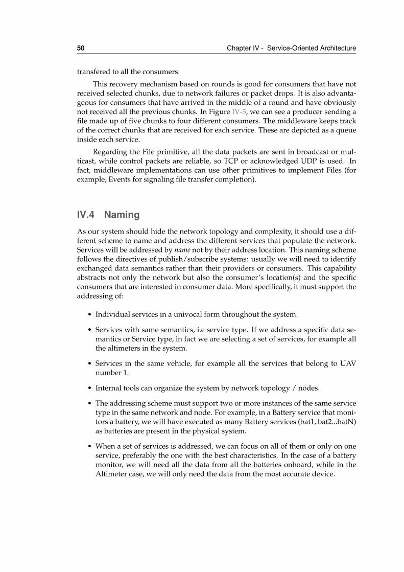
50 Chapter IV - Service-Oriented Architecture
transfered to all the consumers.
This recovery mechanism based on rounds is good for consumers that have notreceived selected chunks, due to network failures or packet drops. It is also advanta-geous for consumers that have arrived in the middle of a round and have obviouslynot received all the previous chunks. In Figure IV-5, we can see a producer sending afile made up of five chunks to four different consumers. The middleware keeps trackof the correct chunks that are received for each service. These are depicted as a queueinside each service.
Regarding the File primitive, all the data packets are sent in broadcast or mul-ticast, while control packets are reliable, so TCP or acknowledged UDP is used. Infact, middleware implementations can use other primitives to implement Files (forexample, Events for signaling file transfer completion).
IV.4 NamingAs our system should hide the network topology and complexity, it should use a dif-ferent scheme to name and address the different services that populate the network.Services will be addressed by name not by their address location. This naming schemefollows the directives of publish/subscribe systems: usually we will need to identifyexchanged data semantics rather than their providers or consumers. This capabilityabstracts not only the network but also the consumer’s location(s) and the specificconsumers that are interested in consumer data. More specifically, it must support theaddressing of:
• Individual services in a univocal form throughout the system.
• Services with same semantics, i.e service type. If we address a specific data se-mantics or Service type, in fact we are selecting a set of services, for example allthe altimeters in the system.
• Services in the same vehicle, for example all the services that belong to UAVnumber 1.
• Internal tools can organize the system by network topology / nodes.
• The addressing scheme must support two or more instances of the same servicetype in the same network and node. For example, in a Battery service that moni-tors a battery, we will have executed as many Battery services (bat1, bat2...batN)as batteries are present in the physical system.
• When a set of services is addressed, we can focus on all of them or only on oneservice, preferably the one with the best characteristics. In the case of a batterymonitor, we will need all the data from all the batteries onboard, while in theAltimeter case, we will only need the data from the most accurate device.

IV.4 Naming 51
• Finally, the services define several communication primitives that also need tobe addressed. For example, we will want to receive the current voltage or theestimated duration of the battery from a Battery service.
IV.4.1 Services OrganizationThe organization of services is defined on several levels, as shown in Figure IV-7. Thefull system is composed of several subsystems. Each subsystem represents a vehicleor unit in the system. Strictly, a subsystem is a logical grouping of components thatis spread across one or more nodes. Then, each operational subsystem is composedof one or more nodes. A node contains either a single processor or a tightly coupledset of processors. Each node executes one or more service instances. Each of theseinstances is a different execution of a Service. Finally, each Service has a set of com-munication primitives that also need to be addressed, as can be seen from the differentinput/output ports of the service.
Figure IV-6: JAUS Organization
This organization resembles that defined in JAUS (Joint Architecture for Un-manned Systems (JAUS) Working Group, n.d.). However, their subsystem level usu-ally defines the local network in which the nodes can communicate directly without anadditional communicator component. In our case, the subsystem is a tag or attributeof each service instance (see Figure IV-6). Different subsystems can be deployed in thesame network and in the same node. In addition, JAUS does not define addressablecommunication primitives, as they use globally assigned messages between compo-nents.
In the Figure, three different subsystems are shown: Subsystem 1, Subsystem andSubsystem N. Subsystems 1 and 2 have two nodes each, while Subsystem N only hasone node. Each node can execute one or more service instances. For example, Node1 executes instance 1 of type Service 1 and instance 2 of type Service 2, while Node2 only executes one instance: instance 3 of type Service 3. It is important to note thedifference between a Service and an Instance. A Service represents the type, whileinstances are its running instantiations. For example, there are two running instancesof Service 3: one in node 2 named instance 3 and another in Node 4 named instance 6.
52 Chapter IV - Service-Oriented Architecture
Figure IV-7: Services organization
The information from these four layers is represented in text form as an URL:
/<subsystem>/<node>/<instance>/<service>/<primitive>
For example /Subsystem 2/Node 3/Service 4/instance4/primitive 2 is the URL of the primitive marked in red in Figure IV-7.
The naming scheme supports the selection of sets of services by specifying thatwe do not mind which elements the system selects at the level of the naming hier-archy. This is done by specifying * (reading any) in the corresponding field of theURL. For example /Subsystem 1/*/*/* means all the services of Subsystem 1 and/Subsystem 1/Node 2/*/Service 3 means all the Service 3 type instances inNode 2 belonging to Subsystem 1, regardless of their instance name.
Usually, one service that fulfills the specified URL “description” is enough to im-plement the desired behaviour. However, sometimes all the services addressed bythe URL are necessary. Two examples could be: the use of data from all the Bat-tery services to obtain an overall view of the energy status of the system, and an Al-timeter service that receives the altitude from all the altimeter devices in the systemand computes a new altitude value by using sensor fusion algorithms. To specify allthe services in the result of the search, we add a * before the subsystem field. Thisway, */*/*/*/Battery will gather all the Battery services for the first example,and */Aircraft 1/*/*/Altimeter will gather all the Altimeter data for aircraftnumber 1 in example 2.
The URLs that address services in our system can be rather long. However, thetypical usage has several fields with predetermined values. The typical URL is ofthe form //<default_subsystem>/*/*/<service>. This means that we need
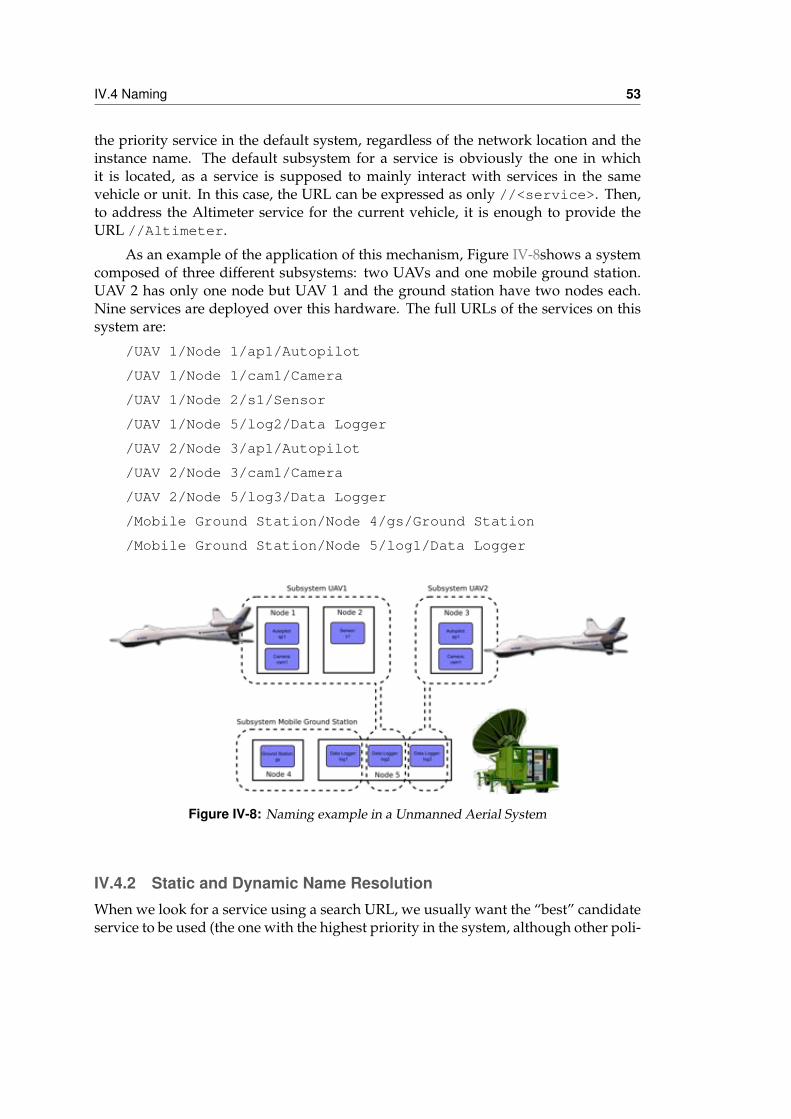
IV.4 Naming 53
the priority service in the default system, regardless of the network location and theinstance name. The default subsystem for a service is obviously the one in whichit is located, as a service is supposed to mainly interact with services in the samevehicle or unit. In this case, the URL can be expressed as only //<service>. Then,to address the Altimeter service for the current vehicle, it is enough to provide theURL //Altimeter.
As an example of the application of this mechanism, Figure IV-8shows a systemcomposed of three different subsystems: two UAVs and one mobile ground station.UAV 2 has only one node but UAV 1 and the ground station have two nodes each.Nine services are deployed over this hardware. The full URLs of the services on thissystem are:
/UAV 1/Node 1/ap1/Autopilot
/UAV 1/Node 1/cam1/Camera
/UAV 1/Node 2/s1/Sensor
/UAV 1/Node 5/log2/Data Logger
/UAV 2/Node 3/ap1/Autopilot
/UAV 2/Node 3/cam1/Camera
/UAV 2/Node 5/log3/Data Logger
/Mobile Ground Station/Node 4/gs/Ground Station
/Mobile Ground Station/Node 5/log1/Data Logger
Figure IV-8: Naming example in a Unmanned Aerial System
IV.4.2 Static and Dynamic Name ResolutionWhen we look for a service using a search URL, we usually want the “best” candidateservice to be used (the one with the highest priority in the system, although other poli-
54 Chapter IV - Service-Oriented Architecture
cies are possible). The service ranking by priority can change over time as new servicesare connected to the system, or as active ones become disconnected or fail. This dy-namic name resolution mechanism is transparent to the consumer services, and allowsthe deployment of several identical services in the same network for redundancy.
However, in other cases we want to use the same concrete service instance allthe time. This is the case when the Services provide different data (even though theyprovide data with the same semantic), for example in the case of the Battery service,or when the service requires a communicating sequence (a protocol). An example of aservice that requires a very simple protocol is the Camera service. This service requiresa Start call, and after the desired video sequence has been acquired, it should receive aStop call to switch down the power-hungry hardware. If we send this Stop to anotherCamera service in the system, we will not have the desired effect.
In these cases, we want to use a static name resolution at the consumption time.Static resolution implies that if the service fails or shutdowns, the consumer serviceswill be notified of this problem, but they cannot recover by changing to anotherprovider service automatically by means of the middleware.
Static name resolution can be attained by specifying the full name of a service(no * in the URL pattern) or by using a lock. If we add an exclamation mark (!) at thebeginning of an URL, a discovery and search procedure will be performed at the con-sumption time. From the resulting set of services, the priority service will be chosenand its full name will be computed. For the rest of the time-line, the system will bestuck with this service. For example, !/Aircraft 1/*/*/Altimeter looks for allthe altimeters of aircraft number 1 and locks the one with the highest priority.
This static resolution can also be used for sets of services by using the #mark. Forexample, */Aircraft 1/*/*/Battery means all the batteries for aircraft number1 and #/Aircraft 1/*/*/Battery means all the batteries at the search time. Ifnew Battery services are added to the system or existing ones are removed they willnot be taken into account. Static name resolution for sets is in fact a shortcut to traverseall the results of the search and apply and individually lock them.
IV.5 Service DescriptionServices are designed to be outwardly descriptive so that they can be found via dis-covery mechanisms. Descriptions can be easily written using XML files. In the listingIV.1, we can see the XML that describes the Altimeter service. The <description>tag contains a textual definition of both the services and its primitives. Variables andevents can declare some additional characteristics. In this case, we can see that thealtitude variable is expressed in meters, its value is between 0 and 15000 meters, andit has a refresh rate of 20Hz. The detailed syntax of the service description files will begiven in Chapter V.
Listing IV.1: Service description in XML
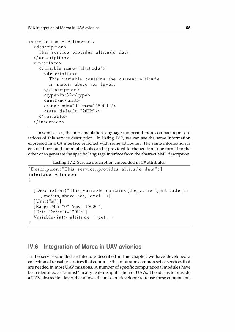
IV.6 Integration of Marea in UAV avionics 55
< s e r v i c e name=" Alt imeter ">< d e s c r i p t i o n >
This s e r v i c e provides a l t i t u d e data .</ d e s c r i p t i o n >< i n t e r f a c e >
< v a r i a b l e name=" a l t i t u d e ">< d e s c r i p t i o n >
This v a r i a b l e conta ins the current a l t i t u d ein meters above sea l e v e l .
</ d e s c r i p t i o n ><type> i n t 3 2 </type><uni t>m</uni t><range min=" 0 " max=" 15000 "/>< r a t e default=" 20Hz"/>
</ v a r i a b l e ></ i n t e r f a c e >
In some cases, the implementation language can permit more compact represen-tations of this service description. In listing IV.2, we can see the same informationexpressed in a C# interface enriched with some attributes. The same information isencoded here and automatic tools can be provided to change from one format to theother or to generate the specific language interface from the abstract XML description.
Listing IV.2: Service description embedded in C# attributes[ Descr ipt ion ( " This s e r v i c e provides a l t i t u d e data " ) ]i n t e r f a c e Alt imeter{
[ Descr ipt ion ( " This v a r i a b l e conta ins the current a l t i t u d e inmeters above sea l e v e l . " ) ]
[ Unit ( "m" ) ][ Range Min=" 0 " Max=" 15000 " ][ Rate Defaul t=" 20Hz" ]Variable < int > a l t i t u d e { get ; }
}
IV.6 Integration of Marea in UAV avionicsIn the service-oriented architecture described in this chapter, we have developed acollection of reusable services that comprise the minimum common set of services thatare needed in most UAV missions. A number of specific computational modules havebeen identified as “a must” in any real-life application of UAVs. The idea is to providea UAV abstraction layer that allows the mission developer to reuse these components
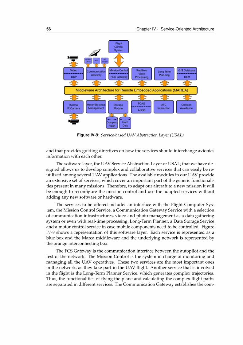
56 Chapter IV - Service-Oriented Architecture
Figure IV-9: Service-based UAV Abstraction Layer (USAL)
and that provides guiding directives on how the services should interchange avionicsinformation with each other.
The software layer, the UAV Service Abstraction Layer or USAL, that we have de-signed allows us to develop complex and collaborative services that can easily be re-utilized among several UAV applications. The available modules in our UAV providean extensive set of services, which cover an important part of the generic functionali-ties present in many missions. Therefore, to adapt our aircraft to a new mission it willbe enough to reconfigure the mission control and use the adapted services withoutadding any new software or hardware.
The services to be offered include: an interface with the Flight Computer Sys-tem, the Mission Control Service, a Communication Gateway Service with a selectionof communication infrastructures, video and photo management as a data gatheringsystem or even with real-time processing, Long-Term Planner, a Data Storage Serviceand a motor control service in case mobile components need to be controlled. FigureIV-9 shows a representation of this software layer. Each service is represented as ablue box and the Marea middleware and the underlying network is represented bythe orange interconnecting box.
The FCS Gateway is the communication interface between the autopilot and therest of the network. The Mission Control is the system in charge of monitoring andmanaging all the UAV operatives. These two services are the most important onesin the network, as they take part in the UAV flight. Another service that is involvedin the flight is the Long-Term Planner Service, which generates complex trajectories.Thus, the functionalities of flying the plane and calculating the complex flight pathsare separated in different services. The Communication Gateway establishes the com-
IV.7 Conclusions 57
munication bridge between the UAV and ground, in order to see the network as awhole. The Engine and the Electrical Managers are in charge of monitoring the en-gine and electrical parameters to detect problems and notify the Mission Control tomanage them.
There are several services to manage the payload, as shown hereafter. The videoand photo services acquire data to send processing services as Real-time Video Pro-cessing. The Storage Module saves video, photos and telemetry so that this data canbe subsequently processed on the ground.
IV.7 ConclusionsService-Oriented Architectures (SOA) have the following advantages: interoperability,flexibility and extensibility, which are making them popular in several domains. AsSOA is an architectural style, several designs and implementations are possible. Marea(Middleware Architecture for Remote Embedded Applications) is the name of ourspecific proposal of SOA for embedded and avionics systems. Marea is based on thedata distribution paradigm for information communication. It promotes a publish-subscribe model for transfering data among nodes. Four communication primitives(variables, events, functions and files) are available for Marea services. This primitivealso covers classical remote procedure calls for legacy applications.
As Marea should hide network topology and address contents by data semanticsand not by network location, a hierarchical naming scheme is also presented. Thismechanism can easily address concrete services and sets of services in a system. Ser-vices are designed to be outwardly descriptive so that they can be found via discoverymechanisms. This description can be done in an XML file or directly in the servicecode. Finally, as an example of how to apply Marea to UAV avionics, the UAV ServiceAbstraction Layer (USAL) is depicted.

VMarea Design and
Implementation
V.1 IntroductionMiddleware-based software systems consist of a network of cooperating components,in our case services, which implement the business logic of the application and an in-tegrating middleware layer that abstracts the execution environment and implementscommon functionalities and communication channels. In this view, the services aresemantic units that behave as producers of data and as a consumers of data comingfrom other services. The localization of the other services is not important because themiddleware manages their discovery. The middleware also handles all the transferchores: message addressing, data marshaling and demarshalling (so subscriber ser-vices can be on different platforms than the publisher service), delivery, flow control,retries, etc. Any service can be a publisher, subscriber, or both simultaneously. Thispublish-subscribe model virtually eliminates complex network programming for dis-tributed applications.
In our architecture, the middleware takes the form of a component called servicecontainer. The services are executed and managed by a service container that is unique
59
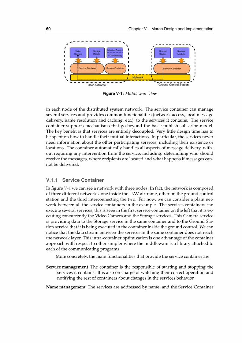
60 Chapter V - Marea Design and Implementation
Figure V-1: Middleware view
in each node of the distributed system network. The service container can manageseveral services and provides common functionalities (network access, local messagedelivery, name resolution and caching, etc.) to the services it contains. The servicecontainer supports mechanisms that go beyond the basic publish-subscribe model.The key benefit is that services are entirely decoupled. Very little design time has tobe spent on how to handle their mutual interactions. In particular, the services neverneed information about the other participating services, including their existence orlocations. The container automatically handles all aspects of message delivery, with-out requiring any intervention from the service, including: determining who shouldreceive the messages, where recipients are located and what happens if messages can-not be delivered.
V.1.1 Service ContainerIn figure V-1 we can see a network with three nodes. In fact, the network is composedof three different networks, one inside the UAV airframe, other on the ground controlstation and the third interconnecting the two. For now, we can consider a plain net-work between all the service containers in the example. The services containers canexecute several services, this is seen in the first service container on the left that it is ex-ecuting concurrently the Video Camera and the Storage services. This Camera serviceis providing data to the Storage service in the same container and to the Ground Sta-tion service that it is being executed in the container inside the ground control. We cannotice that the data stream between the services in the same container does not reachthe network layer. This intra-container optimization is one advantage of the containerapproach with respect to other simpler where the middleware is a library attached toeach of the communicating programs.
More concretely, the main functionalities that provide the service container are:
Service management The container is the responsible of starting and stopping theservices it contains. It is also on charge of watching their correct operation andnotifying the rest of containers about changes in the services behavior.
Name management The services are addressed by name, and the Service Container
V.1 Introduction 61
discovers the real location in the network of the named service. This featureabstracts the programmer from knowing where the service resides or how tocommunicate with it. In case of service malfunctioning, it is also the containerresponsibility to notify the other containers in the domain. In this way, the con-tainers are able to clear and update their caches. From the name managementpoint of view, the Service Container acts as a proxy cache for the services it con-tains.
Network management and abstraction The services do not access the network di-rectly. All their communication is carried by the service container. This abstractsthe network access, allowing the middleware to be deployed in different net-works. Moreover, the container hides the bookkeeping related with the manage-ment of UDP/TCP ports and multicast groups.
Resource management Given that each network distributed node has a unique con-tainer, and that all the services in that node are layered on top of it, the containeris the right place to centralize the management of the shared resources of thenode: memory, CPU time, input/output devices that are accessed in exclusivemode, etc. In some cases, for example when the node is a low-end microcon-troller, the service container can act as a minimal operating system.
V.1.2 Target environmentsFor designing and implementing the Marea middleware we have taken into accountwhich are the target environments in which the middleware is going to be used andwhich are the desired characteristics and requirements of the system.
The first requirement is that it has to be implemented on an object oriented basis.This requirement affects both on its internal design and also the implementation lan-guages that can be selected. While this is a non-functional requirement, the usage ofobject orientation allows the usage of well-known and proven design patterns duringthe design and development of the middleware. In addition, object orientation bene-fits code reusability. Both the middleware and the services deployed over it should beeasily reusable between different applications and environments. The service orientedarchitecture depicted in chapter IV follows in several ways the directives of object ori-entation so seems coherent to follow them in all the architecture.
The second non-functional requirement of the system is that can be executed on avirtual machine (Goldberg, 1974). While this configuration obviously does not benefitthe overall performance of the system, it generates high improvements in the reusabil-ity of the system. Virtual machine based systems can be easily retargeted in differentarchitectures and operating systems, as the new target environment also has an im-plementation of the virtual machine. As embedded systems are getting more pow-erful this scheme is being more used, the same way it has occurred on desktop andserver environments. In this sense, highly restrictive environments like avionics [Javaen UAV, Boeing] and real-time communications (Malohlava et al. , 2008; Raman et al.
62 Chapter V - Marea Design and Implementation
, 2005) has been successfully implemented with virtual machines. Finally, if perfor-mance is crucial they are appearing hardware architectures that can directly executevirtual machine over the chip (Schoeberl, 2005; Network, n.d.; Schoeberl, 2004)or im-prove their performance by using specific hardware (Porthouse, 2004; Sneha et al. ,2006).
Inside the area of virtual machines, one that is becoming very successful is thestack based ones, being Java (Arnold et al. , 2005; Lindholm & Yellin, 1999) and .NETCLI (Stutz et al. , 2002) the most known representatives. In this case, all the opera-tions are executed inside a stack and no direct operations with memory values areallowed, i.e pointers. This characteristic allows easier verification of the system usingformal verification and other techniques (Hatcliff & Dwyer, 2001; Barnett et al. , 2005;de Brugh et al. , 2009). If the Marea implemented avionics are intended to be used inreal usable airframes this point is something to take into account.
Obviously these requirements are aligned if we are focused on the functional-ity and reusability of the system and not in the highest performance. For this, onlysoft real time constraints are considered. We specifically consider out of scope all theproblematic with hard real-time and determinism typical of very specific systems, forexample autopilots and other certifiable subsystems. The last consideration is that thedesigned architecture and implementation should be usable in systems ranging fromembedded devices to the server software on the ground control station. This allowsto scale the underlying hardware to the specific requirements of the application whilekeeping the same software and making of all of them interoperable by the usage ofthe same middleware.
The chosen implementation environment is Microsoft .NET [REFS]. Marea and itsservices will be implemented in C#. This language is object oriented and very similarto Java and C++ guaranteeing a smooth transition. On the other hand, .NET allowsthe usage of different languages over the same virtual machine and that the programsand libraries written in different languages transparently interact among them. Thisallow that services written in C++ or Ada (Carlisle et al. , 2003; Humphries et al. , 2004)can be integrated into Marea easily. .NET supports more than 40 different languagesto choose.
.NET support three different virtual machine implementations: adaptative com-piler, just in time (JIT) compiler and interpreter, for accommodating different levelsof computational architectures, from ARM microcontrollers to IA64 servers. Being anECMA standard (Ecma, 2005a; Ecma, 2005b), the .NET virtual machine or commonlanguage infrastructure (CLI) has been implemented for both commercial and opensource vendors: Microsoft, Mono, Portable.NET (Weatherley & Gopal, n.d.; Easton &King, 2004). As an example of the architectonic broad support, in table V-1 the archi-tectures and operating systems supported by the Mono implementation are shown.
These three different virtual machine implementations are commonly refereedas the .NET Framework, .NET Compact Framework and .NET Micro Framework re-spectively. The first one is the used on high-end desktop and server computers. Itcomprises not only the run time environment, known as the Common Language Run-
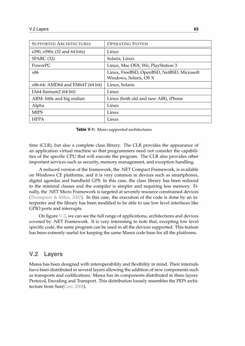
V.2 Layers 63
SUPPORTED ARCHITECTURES OPERATING SYSTEM
s390, s390x (32 and 64 bits) LinuxSPARC (32) Solaris, LinuxPowerPC Linux, Mac OSX, Wii, PlayStation 3x86 Linux, FreeBSD, OpenBSD, NetBSD, Microsoft
Windows, Solaris, OS Xx86-64: AMD64 and EM64T (64 bit) Linux, SolarisIA64 Itanium2 (64 bit) LinuxARM: little and big endian Linux (both old and new ABI), iPhoneAlpha LinuxMIPS LinuxHPPA Linux
Table V-1: Mono supported architectures
time (CLR), but also a complete class library. The CLR provides the appearance ofan application virtual machine so that programmers need not consider the capabili-ties of the specific CPU that will execute the program. The CLR also provides otherimportant services such as security, memory management, and exception handling.
A reduced version of the framework, the .NET Compact Framework, is availableon Windows CE platforms, and it is very common in devices such as smartphones,digital agendas and handheld GPS. In this case, the class library has been reducedto the minimal classes and the compiler is simpler and requiring less memory. Fi-nally, the .NET Micro Framework is targeted at severely resource constrained devices(Thompson & Miles, 2007). In this case, the execution of the code is done by an in-terpreter and the library has been modified to be able to use low level interfaces likeGPIO ports and interrupts.
On figure V-2, we can see the full range of applications, architectures and devicescovered by .NET Framework. It is very interesting to note that, excepting low levelspecific code, the same program can be used in all the devices supported. This featurehas been extremly useful for keeping the same Marea code base for all the platforms.
V.2 LayersMarea has been designed with interoperability and flexibility in mind. Their internalshave been distributed in several layers allowing the addition of new components suchas transports and codifications. Marea has its components distributed in three layers:Protocol, Encoding and Transport. This distribution loosely resembles the PEPt archi-tecture from Sun(Carr, 2004).
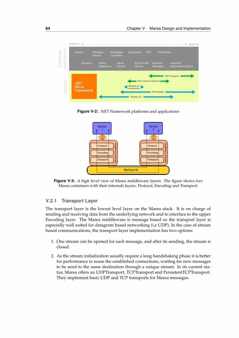
64 Chapter V - Marea Design and Implementation
Figure V-2: .NET Framework platforms and applications
Figure V-3: A high level view of Marea middleware layers. The figure shows twoMarea containers with their internals layers: Protocol, Encoding and Transport.
V.2.1 Transport LayerThe transport layer is the lowest level layer on the Marea stack. It is on charge ofsending and receiving data from the underlying network and to interface to the upperEncoding layer. The Marea middleware is message based so the transport layer isespecially well suited for datagram based networking (i.e UDP). In the case of streambased communications, the transport layer implementation has two options:
1. One stream can be opened for each message, and after its sending, the stream isclosed.
2. As the stream initialization usually require a long handshaking phase it is betterfor performance to reuse the established connections, waiting for new messagesto be send to the same destination through a unique stream. In its current sta-tus, Marea offers an UDPTransport, TCPTransport and PersistentTCPTransport.They implement basic UDP and TCP transports for Marea messages.
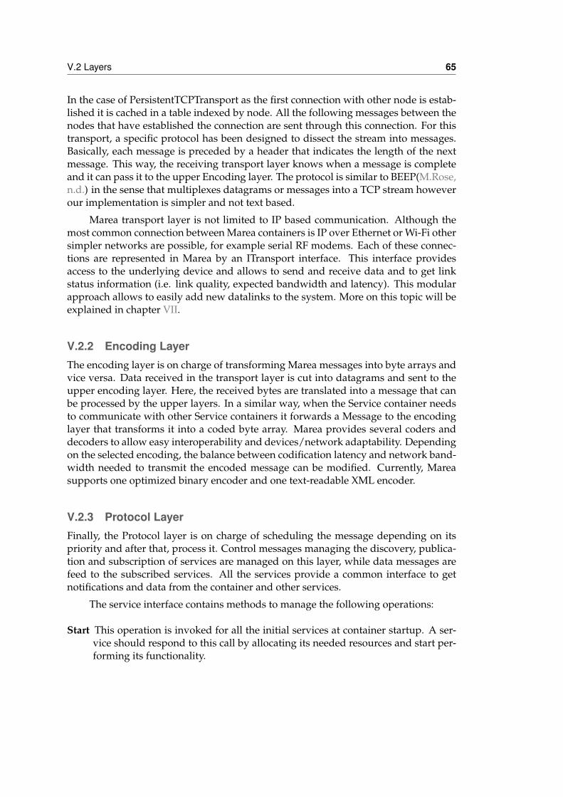
V.2 Layers 65
In the case of PersistentTCPTransport as the first connection with other node is estab-lished it is cached in a table indexed by node. All the following messages between thenodes that have established the connection are sent through this connection. For thistransport, a specific protocol has been designed to dissect the stream into messages.Basically, each message is preceded by a header that indicates the length of the nextmessage. This way, the receiving transport layer knows when a message is completeand it can pass it to the upper Encoding layer. The protocol is similar to BEEP(M.Rose,n.d.) in the sense that multiplexes datagrams or messages into a TCP stream howeverour implementation is simpler and not text based.
Marea transport layer is not limited to IP based communication. Although themost common connection between Marea containers is IP over Ethernet or Wi-Fi othersimpler networks are possible, for example serial RF modems. Each of these connec-tions are represented in Marea by an ITransport interface. This interface providesaccess to the underlying device and allows to send and receive data and to get linkstatus information (i.e. link quality, expected bandwidth and latency). This modularapproach allows to easily add new datalinks to the system. More on this topic will beexplained in chapter VII.
V.2.2 Encoding LayerThe encoding layer is on charge of transforming Marea messages into byte arrays andvice versa. Data received in the transport layer is cut into datagrams and sent to theupper encoding layer. Here, the received bytes are translated into a message that canbe processed by the upper layers. In a similar way, when the Service container needsto communicate with other Service containers it forwards a Message to the encodinglayer that transforms it into a coded byte array. Marea provides several coders anddecoders to allow easy interoperability and devices/network adaptability. Dependingon the selected encoding, the balance between codification latency and network band-width needed to transmit the encoded message can be modified. Currently, Mareasupports one optimized binary encoder and one text-readable XML encoder.
V.2.3 Protocol LayerFinally, the Protocol layer is on charge of scheduling the message depending on itspriority and after that, process it. Control messages managing the discovery, publica-tion and subscription of services are managed on this layer, while data messages arefeed to the subscribed services. All the services provide a common interface to getnotifications and data from the container and other services.
The service interface contains methods to manage the following operations:
Start This operation is invoked for all the initial services at container startup. A ser-vice should respond to this call by allocating its needed resources and start per-forming its functionality.
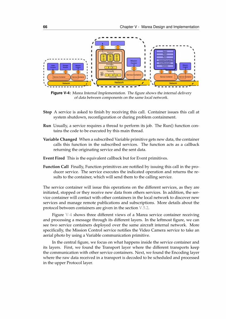
66 Chapter V - Marea Design and Implementation
Figure V-4: Marea Internal Implementation. The figure shows the internal deliveryof data between components on the same local network.
Stop A service is asked to finish by receiving this call. Container issues this call atsystem shutdown, reconfiguration or during problem containment.
Run Usually, a service requires a thread to perform its job. The Run() function con-tains the code to be executed by this main thread.
Variable Changed When a subscribed Variable primitive gets new data, the containercalls this function in the subscribed services. The function acts as a callbackreturning the originating service and the sent data.
Event Fired This is the equivalent callback but for Event primitives.
Function Call Finally, Function primitives are notified by issuing this call in the pro-ducer service. The service executes the indicated operation and returns the re-sults to the container, which will send them to the calling service.
The service container will issue this operations on the different services, as they areinitiated, stopped or they receive new data from others services. In addition, the ser-vice container will contact with other containers in the local network to discover newservices and manage remote publications and subscriptions. More details about theprotocol between containers are given in the section V.5.2.
Figure V-4 shows three different views of a Marea service container receivingand processing a message through its different layers. In the leftmost figure, we cansee two service containers deployed over the same aircraft internal network. Morespecifically, the Mission Control service notifies the Video Camera service to take anaerial photo by using a Variable communication primitive.
In the central figure, we focus on what happens inside the service container andits layers. First, we found the Transport layer where the different transports keepthe communication with other service containers. Next, we found the Encoding layerwhere the raw data received in a transport is decoded to be scheduled and processedin the upper Protocol layer.
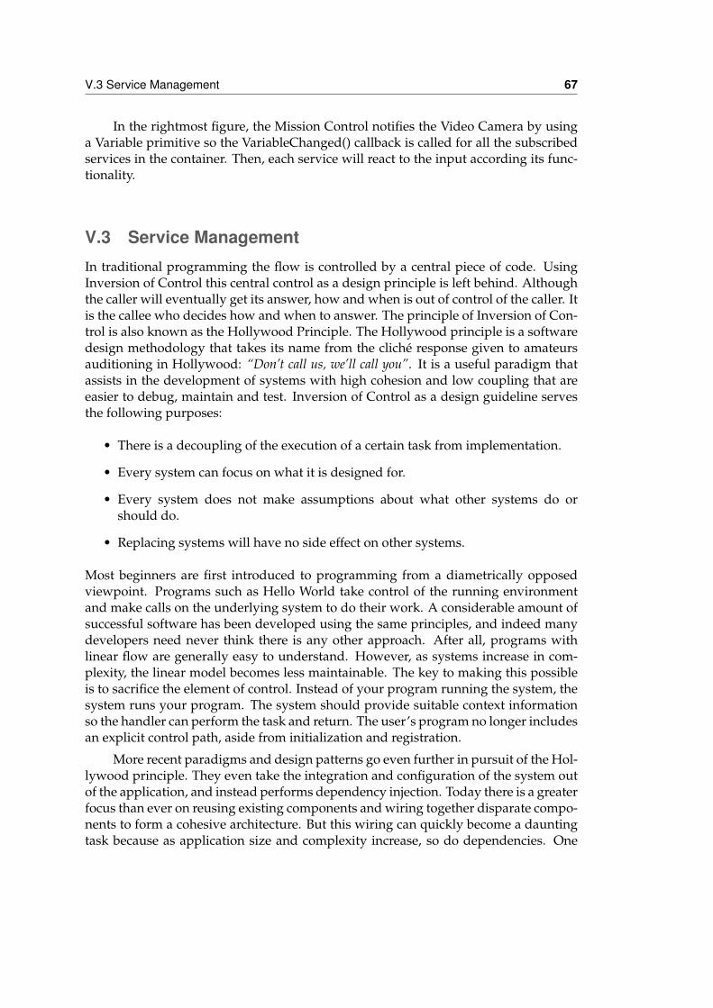
V.3 Service Management 67
In the rightmost figure, the Mission Control notifies the Video Camera by usinga Variable primitive so the VariableChanged() callback is called for all the subscribedservices in the container. Then, each service will react to the input according its func-tionality.
V.3 Service ManagementIn traditional programming the flow is controlled by a central piece of code. UsingInversion of Control this central control as a design principle is left behind. Althoughthe caller will eventually get its answer, how and when is out of control of the caller. Itis the callee who decides how and when to answer. The principle of Inversion of Con-trol is also known as the Hollywood Principle. The Hollywood principle is a softwaredesign methodology that takes its name from the cliché response given to amateursauditioning in Hollywood: “Don’t call us, we’ll call you”. It is a useful paradigm thatassists in the development of systems with high cohesion and low coupling that areeasier to debug, maintain and test. Inversion of Control as a design guideline servesthe following purposes:
• There is a decoupling of the execution of a certain task from implementation.
• Every system can focus on what it is designed for.
• Every system does not make assumptions about what other systems do orshould do.
• Replacing systems will have no side effect on other systems.
Most beginners are first introduced to programming from a diametrically opposedviewpoint. Programs such as Hello World take control of the running environmentand make calls on the underlying system to do their work. A considerable amount ofsuccessful software has been developed using the same principles, and indeed manydevelopers need never think there is any other approach. After all, programs withlinear flow are generally easy to understand. However, as systems increase in com-plexity, the linear model becomes less maintainable. The key to making this possibleis to sacrifice the element of control. Instead of your program running the system, thesystem runs your program. The system should provide suitable context informationso the handler can perform the task and return. The user’s program no longer includesan explicit control path, aside from initialization and registration.
More recent paradigms and design patterns go even further in pursuit of the Hol-lywood principle. They even take the integration and configuration of the system outof the application, and instead performs dependency injection. Today there is a greaterfocus than ever on reusing existing components and wiring together disparate compo-nents to form a cohesive architecture. But this wiring can quickly become a dauntingtask because as application size and complexity increase, so do dependencies. One
68 Chapter V - Marea Design and Implementation
Figure V-5: Container design pattern.
way to mitigate the proliferation of dependencies is by using Dependency Injection(DI), which allows you to inject objects into a class, rather than relying on the class tocreate the object itself.
Containers provide a layer of abstraction in which to house components. DI con-tainers, in particular, reduce the kind of dependency coupling just described by pro-viding generic factory classes that instantiate instances of classes. These instances arethen configured by the container, allowing construction logic to be reused on a broaderlevel.
In the figure V-5, the container design pattern is shown [REF]. On the left of thefigure, there is the container that it is on charge on constructing and building the ob-jects by following the given configuration. On the right of the figure, there is a theclient that request a new object to the container, the container configures the objectpossibly establishing relationships with other components or collaborators of the sys-tem and returns it to the client. In the specific Marea implementation the clients areservices and the objects returned are also services.
The service container does basically three different functions regarding servicemanagement that are going to be described in the following sections: service loading,service description and service startup.
V.3.1 Service Loading and DeploymentServices can be dinamically loaded in a service container. The service executable codecan have several dependencies that must be checked. For simplifying the deploymentof services in several nodes and to allow sending a service code during execution,the deployment unit concept has been developed. A deployment unit is a compressedfile that contains a single module of application code loadable by a service container
V.4 Name Management 69
and a XML file describing the module. Each service is stored in its own deploymentunit. However it can happen that some application code is needed to be shared amongdifferent services, for example, libraries. Three different types of deployment unit areconsidered:
1. Service Deployment Units (SDU). They contain the concrete implementation of aservice and its XML description. This description can contain references to otherdeployment units that must be deployed in the service container for the serviceto be available.
2. Interface Deployment Units (IDU). A service implementation follows a specificinterface. For example both the AP04-AP and the PPZ-AP implement the sameAutopilot interface. The code describing the interface is outside the SDU and putin its own SDU. This way, the interface can be shared among multiple services.For this reason, a SDU will always have a dependency with its correspondingIDU.
3. Finally, some code, specially libraries, can be shared in different services orimplementations. Library Deployment Units (LDU) contain libraries or othershareable data. This separation in multiple deployment units allows not to repli-cate code or data among different services.
V.3.2 Service startup and shutdown.On startup the service container reads an XML file describing its configuration. Thisfile includes the list of services to automatically start. Marea also allows a service tobe started or stopped at any moment during its execution. In any case the SDU andits dependencies must be available. On service startup the container will notify itspresence and all the interested services can start using it. During service shutdown ormalfunctioning the interested services are also notified of the situation.
V.3.3 Service description.All the services are described by its interface. This can be written in a XML file ordirectly in code. In any case, Marea can generate a detailed description of all the ser-vices inside a container. This service model is represented internally using the classesshown in figure V-6.
V.4 Name ManagementIn section IV.4, it has been descripted all the semantics that Marea support for con-structing names of available services in the network. Now, we are going to introducethe data structures that allow this by examining two examples, one refering to a spe-cific service and other referering to a set of compatible services in both cases located
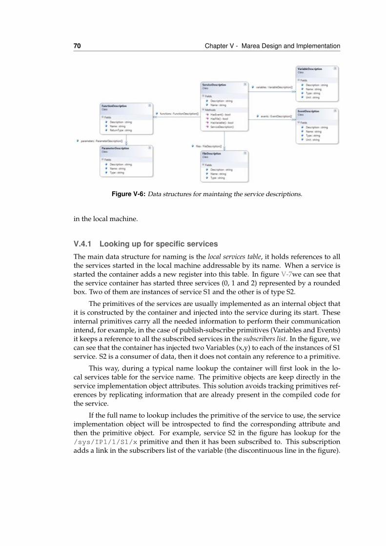
70 Chapter V - Marea Design and Implementation
Figure V-6: Data structures for maintaing the service descriptions.
in the local machine.
V.4.1 Looking up for specific servicesThe main data structure for naming is the local services table, it holds references to allthe services started in the local machine addressable by its name. When a service isstarted the container adds a new register into this table. In figure V-7we can see thatthe service container has started three services (0, 1 and 2) represented by a roundedbox. Two of them are instances of service S1 and the other is of type S2.
The primitives of the services are usually implemented as an internal object thatit is constructed by the container and injected into the service during its start. Theseinternal primitives carry all the needed information to perform their communicationintend, for example, in the case of publish-subscribe primitives (Variables and Events)it keeps a reference to all the subscribed services in the subscribers list. In the figure, wecan see that the container has injected two Variables (x,y) to each of the instances of S1service. S2 is a consumer of data, then it does not contain any reference to a primitive.
This way, during a typical name lookup the container will first look in the lo-cal services table for the service name. The primitive objects are keep directly in theservice implementation object attributes. This solution avoids tracking primitives ref-erences by replicating information that are already present in the compiled code forthe service.
If the full name to lookup includes the primitive of the service to use, the serviceimplementation object will be introspected to find the corresponding attribute andthen the primitive object. For example, service S2 in the figure has lookup for the/sys/IP1/1/S1/x primitive and then it has been subscribed to. This subscriptionadds a link in the subscribers list of the variable (the discontinuous line in the figure).
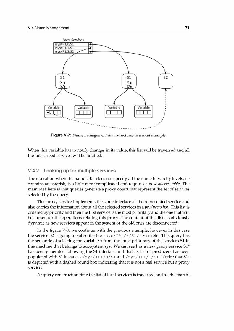
V.4 Name Management 71
Figure V-7: Name management data structures in a local example.
When this variable has to notify changes in its value, this list will be traversed and allthe subscribed services will be notified.
V.4.2 Looking up for multiple servicesThe operation when the name URL does not specify all the name hierarchy levels, i.econtains an asterisk, is a little more complicated and requires a new queries table. Themain idea here is that queries generate a proxy object that represent the set of servicesselected by the query.
This proxy service implements the same interface as the represented service andalso carries the information about all the selected services in a producers list. This list isordered by priority and then the first service is the most prioritary and the one that willbe chosen for the operations relating this proxy. The content of this lists is obviouslydynamic as new services appear in the system or the old ones are disconnected.
In the figure V-8, we continue with the previous example, however in this casethe service S2 is going to subscribe the /sys/IP1/*/S1/x variable. This query hasthe semantic of selecting the variable x from the most prioritary of the services S1 inthis machine that belongs to subsystem sys. We can see has a new proxy service S1*has been generated following the S1 interface and that its list of producers has beenpopulated with S1 instances /sys/IP1/0/S1 and /sys/IP1/1/S1. Notice that S1*is depicted with a dashed round box indicating that it is not a real service but a proxyservice.
At query construction time the list of local services is traversed and all the match-
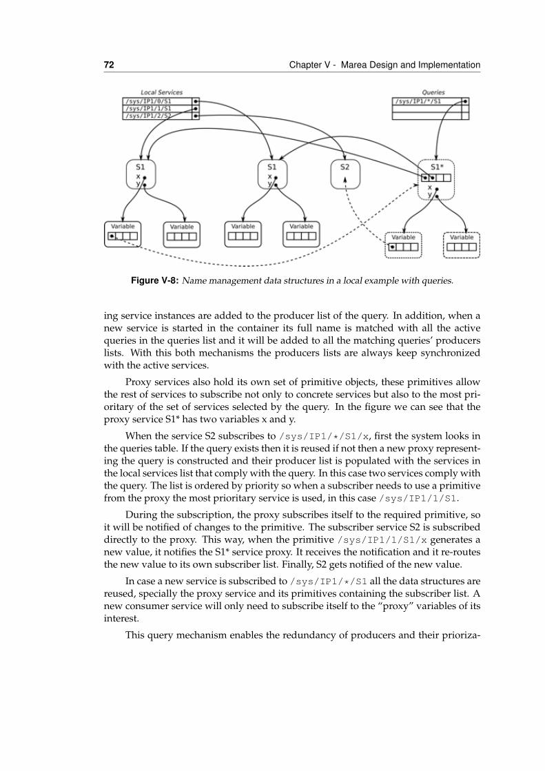
72 Chapter V - Marea Design and Implementation
Figure V-8: Name management data structures in a local example with queries.
ing service instances are added to the producer list of the query. In addition, when anew service is started in the container its full name is matched with all the activequeries in the queries list and it will be added to all the matching queries’ producerslists. With this both mechanisms the producers lists are always keep synchronizedwith the active services.
Proxy services also hold its own set of primitive objects, these primitives allowthe rest of services to subscribe not only to concrete services but also to the most pri-oritary of the set of services selected by the query. In the figure we can see that theproxy service S1* has two variables x and y.
When the service S2 subscribes to /sys/IP1/*/S1/x, first the system looks inthe queries table. If the query exists then it is reused if not then a new proxy represent-ing the query is constructed and their producer list is populated with the services inthe local services list that comply with the query. In this case two services comply withthe query. The list is ordered by priority so when a subscriber needs to use a primitivefrom the proxy the most prioritary service is used, in this case /sys/IP1/1/S1.
During the subscription, the proxy subscribes itself to the required primitive, soit will be notified of changes to the primitive. The subscriber service S2 is subscribeddirectly to the proxy. This way, when the primitive /sys/IP1/1/S1/x generates anew value, it notifies the S1* service proxy. It receives the notification and it re-routesthe new value to its own subscriber list. Finally, S2 gets notified of the new value.
In case a new service is subscribed to /sys/IP1/*/S1 all the data structures arereused, specially the proxy service and its primitives containing the subscriber list. Anew consumer service will only need to subscribe itself to the “proxy” variables of itsinterest.
This query mechanism enables the redundancy of producers and their prioriza-
V.5 Network Abstraction and Management 73
tion. In case a new service appears that matches an existing query it will be addedin priority order to the producers list. If as a result of this insertion on the producerslist the top of the list has been modified, then the old subscribtion to the real servicewill be removed and a new one is generated to the new real service on top of the list.All the subscribed services to any of the primitives from the S1* proxy do not needto do anything as the service container does this management automatically and thischange is transparent for them.
In a similar way, if a producer service is disconnected the proxy will receive thedisconnection event from the variable and it will modify the list accordangly. A newsubscription is generated between the new first provider service on the list. This spe-cific case is the one that provides automatic recovery between redundant services. If aservice fails or shutdowns the next available service will be used for providing serviceto all the consumers.
The disconnection event allows to update the affected proxies very fast. Howeverother proxies can contain references to a disconnected service in the publishers list. Forremoving these references, all the queries are traversed when a service is disconnected.If a query matches the service then it is removed from the publishers list of the proxy.
These data structures scheme is also used for queries representing all the servicesthat match the name descriptor, ie */Aircraft 1/*/*/Altimeter. In this case,the generated proxy does not subscribe to the publisher service on the top of the listbut to all the services in the list.
Finally, in section IV.4.2, static name resolution is discussed. For this specificcase, no proxies are generated. The same name resolution algorithm explained in thissection is applied using the same data structures. However, when the producers arelocated the subscriber is statically and directly subscribed to the resolved services.There is no need of proxy because new or disconected services does not affect thesubscription done statically.
V.5 Network Abstraction and ManagementV.5.1 Name management over networkOne of the key features of Marea is the service location transparency. The user of aservice does not need to know the location of the service he wants to use. It can be inthe same machine or in any other node of the network. For implementing this networklocation transparency, Marea uses a service announcement/discovery protocol. Infigure V-9, service S1 is started in machine 1. As we have seen in section V.4.1, theservice is referenced in the local services list of the container, /sys/IP1/0/S1. Thisallows that all the services in the container can found and use it.
When used in a networked environment, the service container send a broadcastmessage announcing this new available service. The Publish message arrives to allthe nodes in the network. Service containers can cache this information and create a
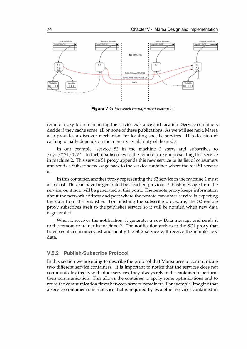
74 Chapter V - Marea Design and Implementation
Figure V-9: Network management example.
remote proxy for remembering the service existance and location. Service containersdecide if they cache some, all or none of these publications. As we will see next, Mareaalso provides a discover mechanism for locating specific services. This decision ofcaching usually depends on the memory availability of the node.
In our example, service S2 in the machine 2 starts and subscribes to/sys/IP1/0/S1. In fact, it subscribes to the remote proxy representing this servicein machine 2. This service S1 proxy appends this new service to its list of consumersand sends a Subscribe message back to the service container where the real S1 serviceis.
In this container, another proxy representing the S2 service in the machine 2 mustalso exist. This can have be generated by a cached previous Publish message from theservice, or, if not, will be generated at this point. The remote proxy keeps informationabout the network address and port where the remote consumer service is expectingthe data from the publisher. For finishing the subscribe procedure, the S2 remoteproxy subscribes itself to the publisher service so it will be notified when new datais generated.
When it receives the notification, it generates a new Data message and sends itto the remote container in machine 2. The notification arrives to the SC1 proxy thattraverses its consumers list and finally the SC2 service will receive the remote newdata.
V.5.2 Publish-Subscribe ProtocolIn this section we are going to describe the protocol that Marea uses to communicatetwo different service containers. It is important to notice that the services does notcommunicate directly with other services, they always rely in the container to performtheir communication. This allows the container to apply some optimizations and toreuse the communication flows between service containers. For example, imagine thata service container runs a service that is required by two other services contained in
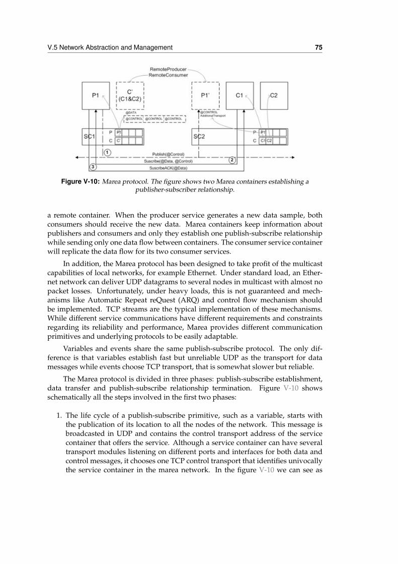
V.5 Network Abstraction and Management 75
Figure V-10: Marea protocol. The figure shows two Marea containers establishing apublisher-subscriber relationship.
a remote container. When the producer service generates a new data sample, bothconsumers should receive the new data. Marea containers keep information aboutpublishers and consumers and only they establish one publish-subscribe relationshipwhile sending only one data flow between containers. The consumer service containerwill replicate the data flow for its two consumer services.
In addition, the Marea protocol has been designed to take profit of the multicastcapabilities of local networks, for example Ethernet. Under standard load, an Ether-net network can deliver UDP datagrams to several nodes in multicast with almost nopacket losses. Unfortunately, under heavy loads, this is not guaranteed and mech-anisms like Automatic Repeat reQuest (ARQ) and control flow mechanism shouldbe implemented. TCP streams are the typical implementation of these mechanisms.While different service communications have different requirements and constraintsregarding its reliability and performance, Marea provides different communicationprimitives and underlying protocols to be easily adaptable.
Variables and events share the same publish-subscribe protocol. The only dif-ference is that variables establish fast but unreliable UDP as the transport for datamessages while events choose TCP transport, that is somewhat slower but reliable.
The Marea protocol is divided in three phases: publish-subscribe establishment,data transfer and publish-subscribe relationship termination. Figure V-10 showsschematically all the steps involved in the first two phases:
1. The life cycle of a publish-subscribe primitive, such as a variable, starts withthe publication of its location to all the nodes of the network. This message isbroadcasted in UDP and contains the control transport address of the servicecontainer that offers the service. Although a service container can have severaltransport modules listening on different ports and interfaces for both data andcontrol messages, it chooses one TCP control transport that identifies univocallythe service container in the marea network. In the figure V-10 we can see as
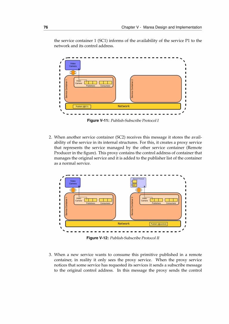
76 Chapter V - Marea Design and Implementation
the service container 1 (SC1) informs of the availability of the service P1 to thenetwork and its control address.
Figure V-11: Publish-Subscribe Protocol I
2. When another service container (SC2) receives this message it stores the avail-ability of the service in its internal structures. For this, it creates a proxy servicethat represents the service managed by the other service container (RemoteProducer in the figure). This proxy contains the control address of container thatmanages the original service and it is added to the publisher list of the containeras a normal service.
Figure V-12: Publish-Subscribe Protocol II
3. When a new service wants to consume this primitive published in a remotecontainer, in reality it only sees the proxy service. When the proxy servicenotices that some service has requested its services it sends a subscribe messageto the original control address. In this message the proxy sends the control
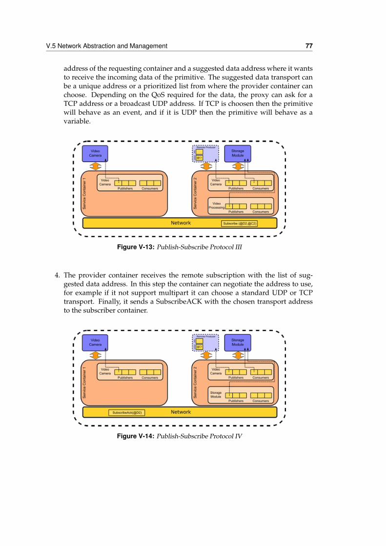
V.5 Network Abstraction and Management 77
address of the requesting container and a suggested data address where it wantsto receive the incoming data of the primitive. The suggested data transport canbe a unique address or a prioritized list from where the provider container canchoose. Depending on the QoS required for the data, the proxy can ask for aTCP address or a broadcast UDP address. If TCP is choosen then the primitivewill behave as an event, and if it is UDP then the primitive will behave as avariable.
Figure V-13: Publish-Subscribe Protocol III
4. The provider container receives the remote subscription with the list of sug-gested data address. In this step the container can negotiate the address to use,for example if it not support multipart it can choose a standard UDP or TCPtransport. Finally, it sends a SubscribeACK with the chosen transport addressto the subscriber container.
Figure V-14: Publish-Subscribe Protocol IV
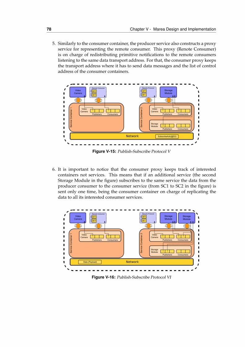
78 Chapter V - Marea Design and Implementation
5. Similarly to the consumer container, the producer service also constructs a proxyservice for representing the remote consumer. This proxy (Renote Consumer)is on charge of redistributing primitive notifications to the remote consumerslistening to the same data transport address. For that, the consumer proxy keepsthe transport address where it has to send data messages and the list of controladdress of the consumer containers.
Figure V-15: Publish-Subscribe Protocol V
6. It is important to notice that the consumer proxy keeps track of interestedcontainers not services. This means that if an additional service (the secondStorage Module in the figure) subscribes to the same service the data from theproducer consumer to the consumer service (from SC1 to SC2 in the figure) issent only one time, being the consumer container on charge of replicating thedata to all its interested consumer services.
Figure V-16: Publish-Subscribe Protocol VI
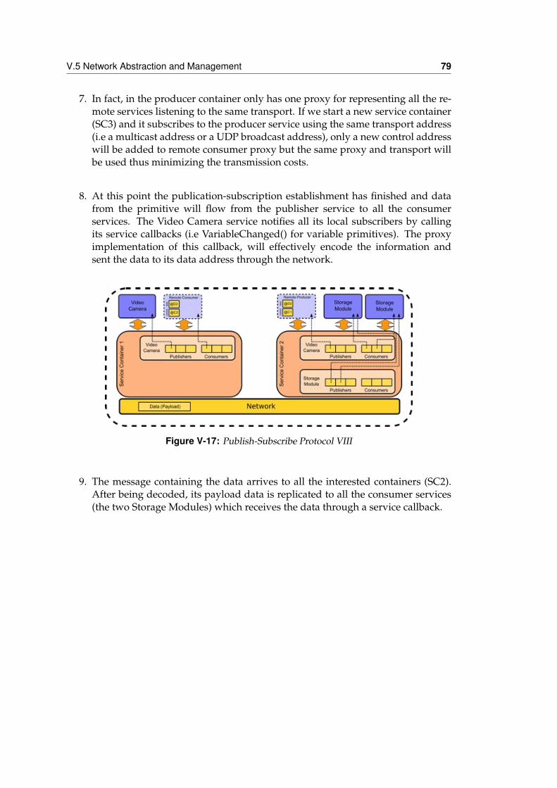
V.5 Network Abstraction and Management 79
7. In fact, in the producer container only has one proxy for representing all the re-mote services listening to the same transport. If we start a new service container(SC3) and it subscribes to the producer service using the same transport address(i.e a multicast address or a UDP broadcast address), only a new control addresswill be added to remote consumer proxy but the same proxy and transport willbe used thus minimizing the transmission costs.
8. At this point the publication-subscription establishment has finished and datafrom the primitive will flow from the publisher service to all the consumerservices. The Video Camera service notifies all its local subscribers by callingits service callbacks (i.e VariableChanged() for variable primitives). The proxyimplementation of this callback, will effectively encode the information andsent the data to its data address through the network.
Figure V-17: Publish-Subscribe Protocol VIII
9. The message containing the data arrives to all the interested containers (SC2).After being decoded, its payload data is replicated to all the consumer services(the two Storage Modules) which receives the data through a service callback.
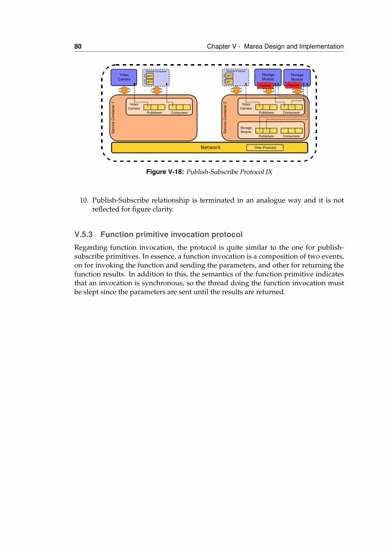
80 Chapter V - Marea Design and Implementation
Figure V-18: Publish-Subscribe Protocol IX
10. Publish-Subscribe relationship is terminated in an analogue way and it is notreflected for figure clarity.
V.5.3 Function primitive invocation protocolRegarding function invocation, the protocol is quite similar to the one for publish-subscribe primitives. In essence, a function invocation is a composition of two events,on for invoking the function and sending the parameters, and other for returning thefunction results. In addition to this, the semantics of the function primitive indicatesthat an invocation is synchronous, so the thread doing the function invocation mustbe slept since the parameters are sent until the results are returned.
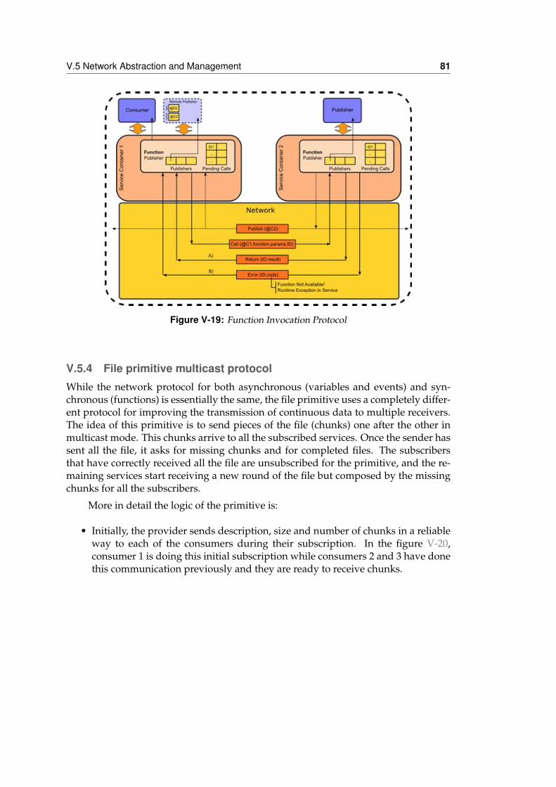
V.5 Network Abstraction and Management 81
Figure V-19: Function Invocation Protocol
V.5.4 File primitive multicast protocolWhile the network protocol for both asynchronous (variables and events) and syn-chronous (functions) is essentially the same, the file primitive uses a completely differ-ent protocol for improving the transmission of continuous data to multiple receivers.The idea of this primitive is to send pieces of the file (chunks) one after the other inmulticast mode. This chunks arrive to all the subscribed services. Once the sender hassent all the file, it asks for missing chunks and for completed files. The subscribersthat have correctly received all the file are unsubscribed for the primitive, and the re-maining services start receiving a new round of the file but composed by the missingchunks for all the subscribers.
More in detail the logic of the primitive is:
• Initially, the provider sends description, size and number of chunks in a reliableway to each of the consumers during their subscription. In the figure V-20,consumer 1 is doing this initial subscription while consumers 2 and 3 have donethis communication previously and they are ready to receive chunks.
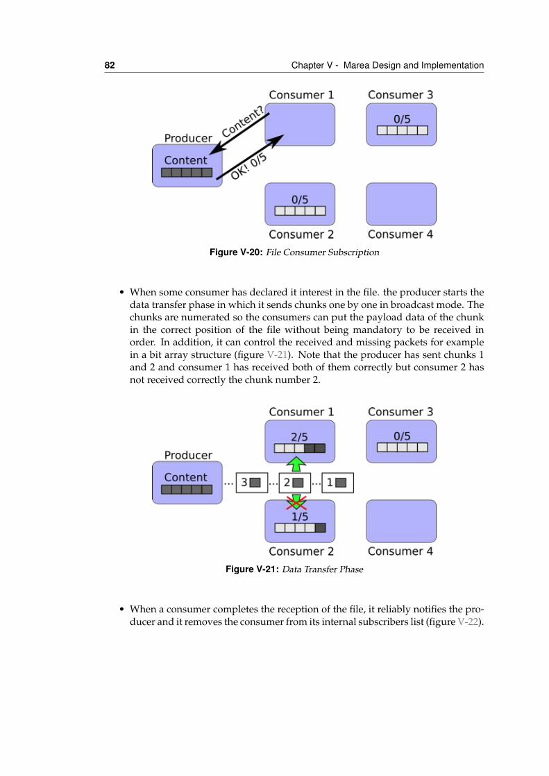
82 Chapter V - Marea Design and Implementation
Figure V-20: File Consumer Subscription
• When some consumer has declared it interest in the file. the producer starts thedata transfer phase in which it sends chunks one by one in broadcast mode. Thechunks are numerated so the consumers can put the payload data of the chunkin the correct position of the file without being mandatory to be received inorder. In addition, it can control the received and missing packets for examplein a bit array structure (figure V-21). Note that the producer has sent chunks 1and 2 and consumer 1 has received both of them correctly but consumer 2 hasnot received correctly the chunk number 2.
Figure V-21: Data Transfer Phase
• When a consumer completes the reception of the file, it reliably notifies the pro-ducer and it removes the consumer from its internal subscribers list (figure V-22).
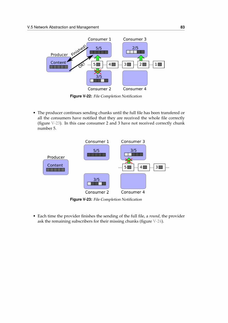
V.5 Network Abstraction and Management 83
Figure V-22: File Completion Notification
• The producer continues sending chunks until the full file has been transfered orall the consumers have notified that they are received the whole file correctly(figure V-23). In this case consumer 2 and 3 have not received correctly chunknumber 5.
Figure V-23: File Completion Notification
• Each time the provider finishes the sending of the full file, a round, the providerask the remaining subscribers for their missing chunks (figure V-24).
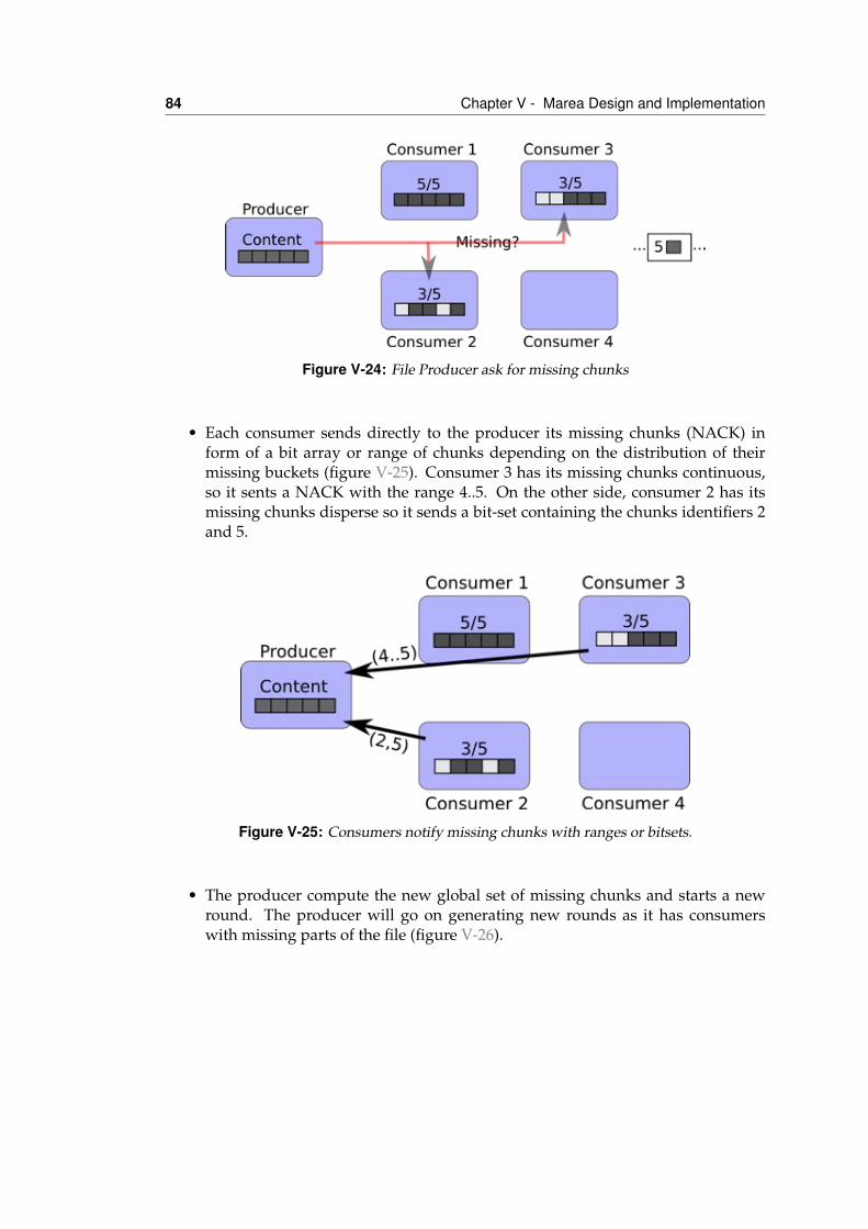
84 Chapter V - Marea Design and Implementation
Figure V-24: File Producer ask for missing chunks
• Each consumer sends directly to the producer its missing chunks (NACK) inform of a bit array or range of chunks depending on the distribution of theirmissing buckets (figure V-25). Consumer 3 has its missing chunks continuous,so it sents a NACK with the range 4..5. On the other side, consumer 2 has itsmissing chunks disperse so it sends a bit-set containing the chunks identifiers 2and 5.
Figure V-25: Consumers notify missing chunks with ranges or bitsets.
• The producer compute the new global set of missing chunks and starts a newround. The producer will go on generating new rounds as it has consumerswith missing parts of the file (figure V-26).
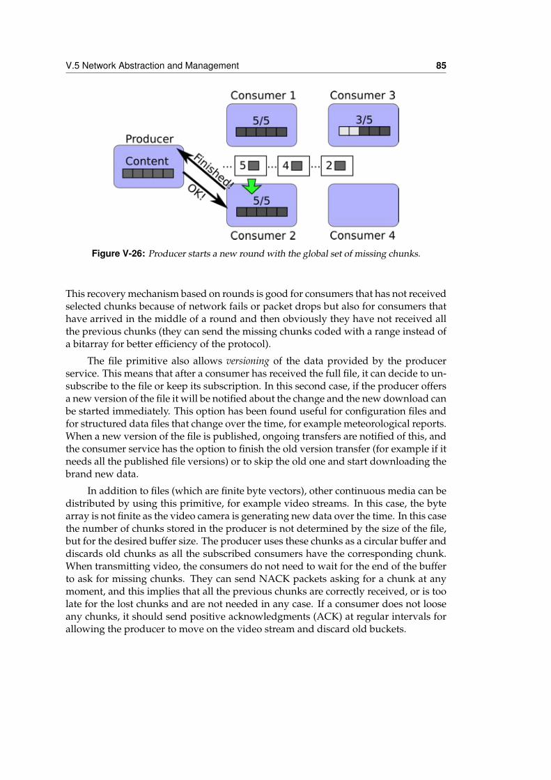
V.5 Network Abstraction and Management 85
Figure V-26: Producer starts a new round with the global set of missing chunks.
This recovery mechanism based on rounds is good for consumers that has not receivedselected chunks because of network fails or packet drops but also for consumers thathave arrived in the middle of a round and then obviously they have not received allthe previous chunks (they can send the missing chunks coded with a range instead ofa bitarray for better efficiency of the protocol).
The file primitive also allows versioning of the data provided by the producerservice. This means that after a consumer has received the full file, it can decide to un-subscribe to the file or keep its subscription. In this second case, if the producer offersa new version of the file it will be notified about the change and the new download canbe started immediately. This option has been found useful for configuration files andfor structured data files that change over the time, for example meteorological reports.When a new version of the file is published, ongoing transfers are notified of this, andthe consumer service has the option to finish the old version transfer (for example if itneeds all the published file versions) or to skip the old one and start downloading thebrand new data.
In addition to files (which are finite byte vectors), other continuous media can bedistributed by using this primitive, for example video streams. In this case, the bytearray is not finite as the video camera is generating new data over the time. In this casethe number of chunks stored in the producer is not determined by the size of the file,but for the desired buffer size. The producer uses these chunks as a circular buffer anddiscards old chunks as all the subscribed consumers have the corresponding chunk.When transmitting video, the consumers do not need to wait for the end of the bufferto ask for missing chunks. They can send NACK packets asking for a chunk at anymoment, and this implies that all the previous chunks are correctly received, or is toolate for the lost chunks and are not needed in any case. If a consumer does not looseany chunks, it should send positive acknowledgments (ACK) at regular intervals forallowing the producer to move on the video stream and discard old buckets.
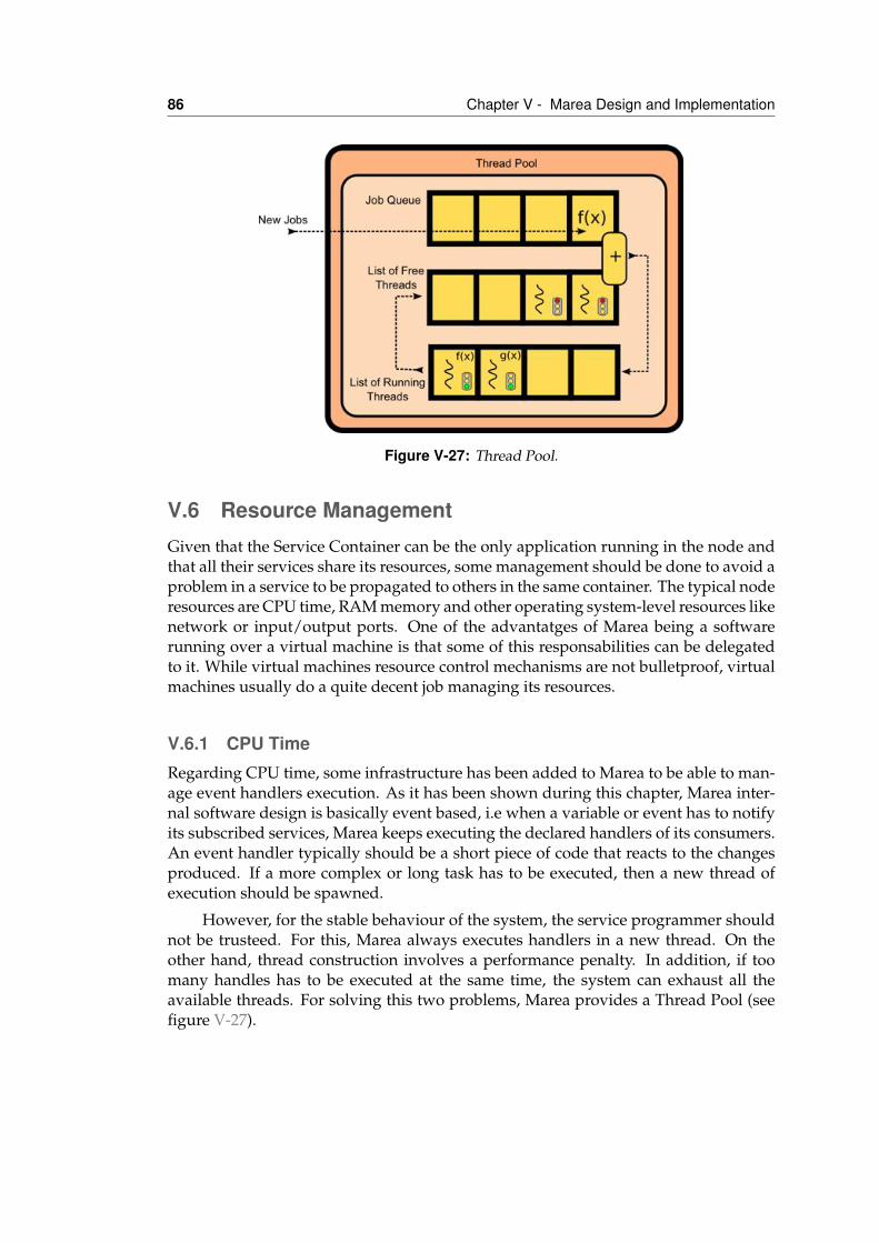
86 Chapter V - Marea Design and Implementation
Figure V-27: Thread Pool.
V.6 Resource ManagementGiven that the Service Container can be the only application running in the node andthat all their services share its resources, some management should be done to avoid aproblem in a service to be propagated to others in the same container. The typical noderesources are CPU time, RAM memory and other operating system-level resources likenetwork or input/output ports. One of the advantatges of Marea being a softwarerunning over a virtual machine is that some of this responsabilities can be delegatedto it. While virtual machines resource control mechanisms are not bulletproof, virtualmachines usually do a quite decent job managing its resources.
V.6.1 CPU TimeRegarding CPU time, some infrastructure has been added to Marea to be able to man-age event handlers execution. As it has been shown during this chapter, Marea inter-nal software design is basically event based, i.e when a variable or event has to notifyits subscribed services, Marea keeps executing the declared handlers of its consumers.An event handler typically should be a short piece of code that reacts to the changesproduced. If a more complex or long task has to be executed, then a new thread ofexecution should be spawned.
However, for the stable behaviour of the system, the service programmer shouldnot be trusteed. For this, Marea always executes handlers in a new thread. On theother hand, thread construction involves a performance penalty. In addition, if toomany handles has to be executed at the same time, the system can exhaust all theavailable threads. For solving this two problems, Marea provides a Thread Pool (seefigure V-27).
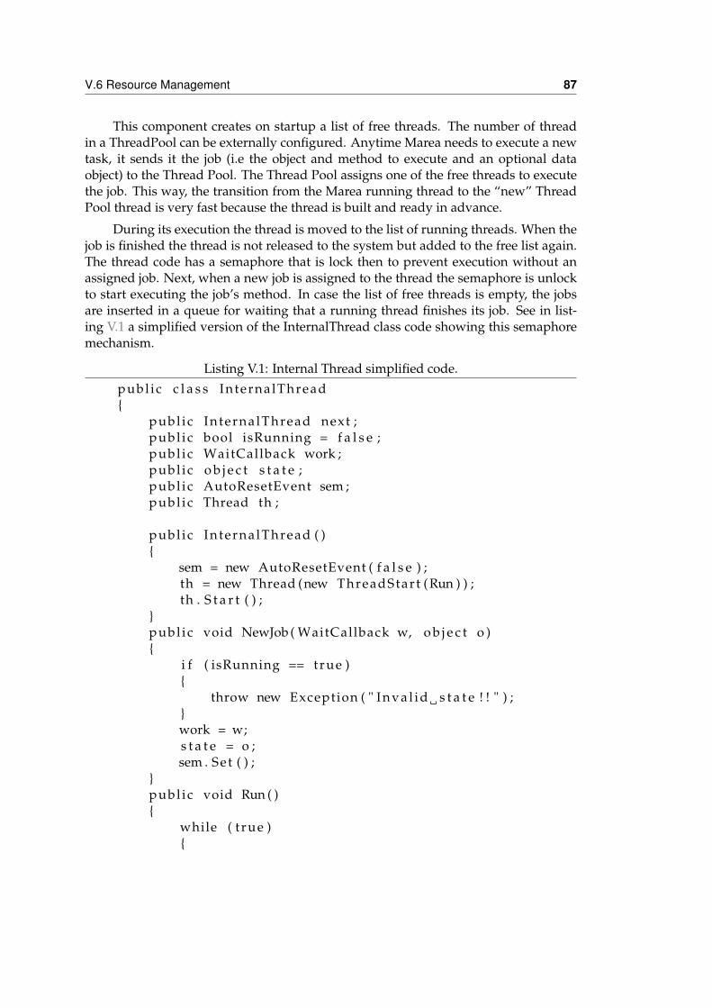
V.6 Resource Management 87
This component creates on startup a list of free threads. The number of threadin a ThreadPool can be externally configured. Anytime Marea needs to execute a newtask, it sends it the job (i.e the object and method to execute and an optional dataobject) to the Thread Pool. The Thread Pool assigns one of the free threads to executethe job. This way, the transition from the Marea running thread to the “new” ThreadPool thread is very fast because the thread is built and ready in advance.
During its execution the thread is moved to the list of running threads. When thejob is finished the thread is not released to the system but added to the free list again.The thread code has a semaphore that is lock then to prevent execution without anassigned job. Next, when a new job is assigned to the thread the semaphore is unlockto start executing the job’s method. In case the list of free threads is empty, the jobsare inserted in a queue for waiting that a running thread finishes its job. See in list-ing V.1 a simplified version of the InternalThread class code showing this semaphoremechanism.
Listing V.1: Internal Thread simplified code.publ ic c l a s s InternalThread{
publ ic InternalThread next ;publ ic bool isRunning = f a l s e ;publ ic WaitCallback work ;publ ic o b j e c t s t a t e ;publ ic AutoResetEvent sem ;publ ic Thread th ;
publ ic InternalThread ( ){
sem = new AutoResetEvent ( f a l s e ) ;th = new Thread (new ThreadStart (Run ) ) ;th . S t a r t ( ) ;
}publ ic void NewJob ( WaitCallback w, o b j e c t o ){
i f ( isRunning == true ){
throw new Exception ( " I n v a l i d s t a t e ! ! " ) ;}work = w;s t a t e = o ;sem . Set ( ) ;
}publ ic void Run ( ){
while ( t rue ){
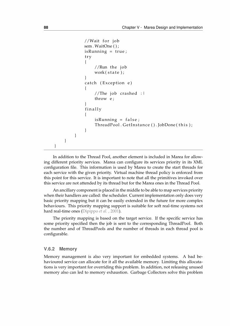
88 Chapter V - Marea Design and Implementation
//Wait f o r jobsem . WaitOne ( ) ;isRunning = true ;t r y{
//Run the jobwork ( s t a t e ) ;
}ca tch ( Exception e ){
//The job crashed : |throw e ;
}f i n a l l y{
isRunning = f a l s e ;ThreadPool . GetInstance ( ) . JobDone ( t h i s ) ;
}}
}}
In addition to the Thread Pool, another element is included in Marea for allow-ing different priority services. Marea can configure its services priority in its XMLconfiguration file. This information is used by Marea to create the start threads foreach service with the given priority. Virtual machine thread policy is enforced fromthis point for this service. It is important to note that all the primitives invoked overthis service are not attended by its thread but for the Marea ones in the Thread Pool.
An ancillary component is placed in the middle to be able to map services prioritywhen their handlers are called: the scheduler. Current implementation only does verybasic priority mapping but it can be easily extended in the future for more complexbehaviours. This priority mapping support is suitable for soft real-time systems nothard real-time ones (Dipippo et al. , 2001).
The priority mapping is based on the target service. If the specific service hassome priority specified then the job is sent to the corresponding ThreadPool. Boththe number and of ThreadPools and the number of threads in each thread pool isconfigurable.
V.6.2 MemoryMemory management is also very important for embedded systems. A bad be-havioured service can allocate for it all the available memory. Limiting this allocata-tions is very important for overriding this problem. In addition, not releasing unusedmemory also can led to memory exhaustion. Garbage Collectors solve this problem
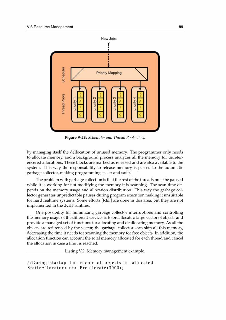
V.6 Resource Management 89
Figure V-28: Scheduler and Thread Pools view.
by managing itself the dellocation of unused memory. The programmer only needsto allocate memory, and a background process analyzes all the memory for unrefer-encered allocations. These blocks are marked as released and are also available to thesystem. This way the responsability to release memory is passed to the automaticgarbage collector, making programming easier and safer.
The problem with garbage collection is that the rest of the threads must be pausedwhile it is working for not modifying the memory it is scanning. The scan time de-pends on the memory usage and allocation distribution. This way the garbage col-lector generates unpredictable pauses during program execution making it unsuitablefor hard realtime systems. Some efforts [REF] are done in this area, but they are notimplemented in the .NET runtime.
One possibility for minimizing garbage collector interruptions and controllingthe memory usage of the different services is to preallocate a large vector of objects andprovide a managed set of functions for allocating and deallocating memory. As all theobjects are referenced by the vector, the garbage collector scan skip all this memory,decreasing the time it needs for scanning the memory for free objects. In addition, theallocation function can account the total memory allocated for each thread and cancelthe allocation in case a limit is reached.
Listing V.2: Memory management example.
//During s t a r t u p the vec tor of o b j e c t s i s a l l o c a t e d .S t a t i c A l l o c a t o r < i n t > . P r e a l l o c a t e ( 3 0 0 0 ) ;
90 Chapter V - Marea Design and Implementation
void f ( ) {// When a new o b j e c t i s needed , the vec tor provides an
unused one .i n t x = S t a t i c A l l o c a t o r < i n t > .New( )
. . .
// The memory i s express ly r e l e a s e d when i t i s used no more .S t a t i c A l l o c a t o r < i n t > . Release ( x ) ;
}
In listing V.2, it can be seen an example of code using this memory management.While this mechanism alleviates the garbage collector stress and allows Marea to mon-itor the services memory usage, it is important to note that requires the programmerconvention to use these memory functions and not the ones provided by the system.
V.7 Example. Multiple battery management system.In this example, a multiple battery management system using Marea services will bespecified and implemented. The system will be composed of a BatteryManager ser-vice on charge of monitoring the charge of the batteries and multiple Battery servicesconnected to the sensing hardware installed in the different battery packs.
V.7.1 InterfacesAs we have seen in the previous sections, all the service interfaces are representedwith a XML file. This file enumerates all the generated outputs and required inputsfor the service. The outputs are represented as communication primitives: variables,events, functions and files, while the inputs can be declared with full service interfacesor with typed communication primitives.
Listing V.3: Battery XML interface.
<namespace name="USAL">< i n t e r f a c e name=" B a t t e r y ">
< d e s c r i p t i o n >This s e r v i c e r e p r e s e n t s a b a t t e r y . </d e s c r i p t i o n >
<output>< v a r i a b l e name=" vol tage " type=" double ">
<uni t>V</uni t>< d e s c r i p t i o n >Voltage of the b a t t e r y . </ d e s c r i p t i o n >
</ v a r i a b l e >
V.7 Example. Multiple battery management system. 91
< v a r i a b l e name=" amperage " type=" double "><uni t>A</uni t>< d e s c r i p t i o n >Current of the b a t t e r y . </ d e s c r i p t i o n >
</ v a r i a b l e ><event name=" amperage " type="None">
< d e s c r i p t i o n >Warns i f the b a t t e r y i s low . </ d e s c r i p t i o n>
</event><funct ion name=" Recharge " type=" void ">
<parameter name=" b " type=" bool "/>< d e s c r i p t i o n >A c t i v a t e s or d e a c t i v a t e s the recharging
mechanism . </ d e s c r i p t i o n ></funct ion>
</output></ i n t e r f a c e >
</namespace>
In listing V.3, the interface of all the battery services is depicted. It basically de-clares four different outputs or results from the Battery service interface: two variablesexposing both the voltage and the amperage of the battery, an event notifying lowcharge condition and finally a function that controls the recharging hardware of thebattery.
In addition to the names, types and description of the semantic of the primitive,additional information can be added to the described primitives: units, minimum andmaximum generation rates, etc. Most of this data is only informational, i.e the unit inwhich the primitive data is expressed, but this information can be accessed in the userimplementation and used for specific applications. For example, at this level the unitinfo can be used for dimensional checking and unit conversion by using a unit librarylike the one defined in JSR-108(Steven Emmerson et al., 2001).
Listing V.4: Battery C# interface.
using Marea ;
namespace USAL{
[ S e r v i c e D e f i n i t i o n ( " This s e r v i c e r e p r e s e n t s a b a t t e r y . " ) ]publ ic i n t e r f a c e B a t t e r y{
[ Descr ipt ion ( " Voltage of the b a t t e r y . " ) ][ Unit ( "V" ) ]Var iab le<double> vol tage { get ; }
[ Descr ipt ion ( " Current of the b a t t e r y . " ) ]
92 Chapter V - Marea Design and Implementation
[ Unit ( "A" ) ]Var iab le<double> amperage { get ; }
[ Descr ipt ion ( " Warns i f the b a t t e r y i s low . " ) ]Event<None> lowBattery { get ; }
[ Descr ipt ion ( " A c t i v a t e s or d e a c t i v a t e s the rechargingmechanism . " ) ]
void Recharge ( bool b ) ;}
}
The service descriptions can be nested in a specific namespace. A namespace is anabstract container or environment created to hold a logical grouping of unique names.Then, a service name defined in a namespace is associated with that namespace. Thesame identifier can be independently defined in multiple namespaces.
In the current C# implementation, not only XML based specifications are possi-ble. We can decorate an standard C# interface definition with several Marea definedattributes: ServiceDefinition, Description, Unit, etc. This attributes supply the Mareaservice containers the same information that it is described in the XML. In listing V.4,it can be seen the same information but encoded in a C# interface.
Generally, this C# based notation is more compact than not the XML one. Inaddition, service containers require a C# interface to cross-check at compile time thatthe user provided implementation complies the service interface. So, a tool is availablein the Marea toolkit to generate the C# interface from the specification in XML andviceversa.
Listing V.5: BatteryManager XML interface.
<namespace name="USAL">< i n t e r f a c e name=" BatteryManager ">
< d e s c r i p t i o n >This i s a b a t t e r y manager . </ d e s c r i p t i o n ><output>
<event name=" globalBatteryWarning " type=" S t r i n g ">< d e s c r i p t i o n >Warns when any of the b a t t e r i e s of the
system i s low . </ d e s c r i p t i o n ></event>
</output></ i n t e r f a c e >
</namespace>
In listings V.5 and V.6, the BatteryManager interface is described both in XMLand C# styles. No new tag appears in this example, it is basically of the same style of
V.7 Example. Multiple battery management system. 93
the previous Battery interface.
The BatteryManager interface declares an output event that will be fired whenany of the batteries reaches a low battery condition. For being able to discriminatewhich is the battery with low charge among all the batteries in the system, this globalbattery warning event will carry a string with the name of the problematic battery.
Listing V.6: BatteryManager C# interface.
using System ;using Marea ;
namespace USAL{
[ S e r v i c e D e f i n i t i o n ( " This i s a b a t t e r y manager . " ) ]publ ic i n t e r f a c e BatteryManager{
[ Descr ipt ion ( " Warns when any of the b a t t e r i e s of thesystem i s low . " ) ]
Event< S t r i n g > globalBatteryWarning { get ; }}
}
V.7.2 Service ImplementationThe service definition only declares which is the minimal interface implemented for allthe compliant implementations. Obviously, each different battery package hardwarewill require a different service implementation. However, as the implementation de-tails are hidden under the same compatible interface, all the Battery implementationsare interoperable and all the services using this interface, i.e the BatteryManager willnot notice the differences among implementations.
Listing V.7: HWBattery service implementation.
using System ;using System . C o l l e c t i o n s . Generic ;using System . Threading ;using USAL;using Marea ;
namespace S e r v i c e s{
/**
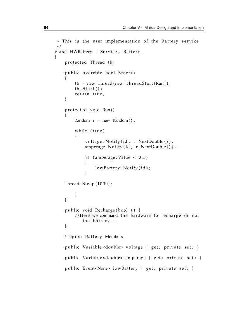
94 Chapter V - Marea Design and Implementation
* This i s the user implementation of the B a t t e r y s e r v i c e*/
c l a s s HWBattery : Service , B a t t e r y{
protec ted Thread th ;
publ ic overr ide bool S t a r t ( ){
th = new Thread (new ThreadStart (Run) ) ;th . S t a r t ( ) ;re turn true ;
}
protec ted void Run ( ){
Random r = new Random ( ) ;
while ( t rue ){
vol tage . Notify ( id , r . NextDouble ( ) ) ;amperage . Notify ( id , r . NextDouble ( ) ) ;
i f ( amperage . Value < 0 . 5 ){
lowBattery . Notify ( id ) ;}
Thread . Sleep ( 1 0 0 0 ) ;
}}
publ ic void Recharge ( bool t ) {//Here we command the hardware to recharge or not
the b a t t e r y . . .}
# region B a t te r y Members
publ ic Variable <double> vol tage { get ; p r i v a t e s e t ; }
publ ic Var iab le<double> amperage { get ; p r i v a t e s e t ; }
publ ic Event<None> lowBattery { get ; p r i v a t e s e t ; }
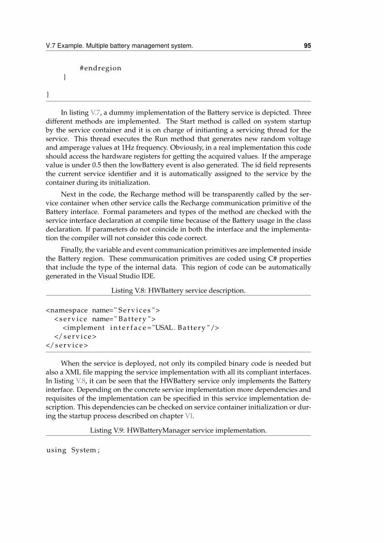
V.7 Example. Multiple battery management system. 95
# endregion}
}
In listing V.7, a dummy implementation of the Battery service is depicted. Threedifferent methods are implemented. The Start method is called on system startupby the service container and it is on charge of initianting a servicing thread for theservice. This thread executes the Run method that generates new random voltageand amperage values at 1Hz frequency. Obviously, in a real implementation this codeshould access the hardware registers for getting the acquired values. If the amperagevalue is under 0.5 then the lowBattery event is also generated. The id field representsthe current service identifier and it is automatically assigned to the service by thecontainer during its initialization.
Next in the code, the Recharge method will be transparently called by the ser-vice container when other service calls the Recharge communication primitive of theBattery interface. Formal parameters and types of the method are checked with theservice interface declaration at compile time because of the Battery usage in the classdeclaration. If parameters do not coincide in both the interface and the implementa-tion the compiler will not consider this code correct.
Finally, the variable and event communication primitives are implemented insidethe Battery region. These communication primitives are coded using C# propertiesthat include the type of the internal data. This region of code can be automaticallygenerated in the Visual Studio IDE.
Listing V.8: HWBattery service description.
<namespace name=" S e r v i c e s ">< s e r v i c e name=" B a t t e r y ">
<implement i n t e r f a c e ="USAL. B a t t e r y "/></ s e r v i c e >
</ s e r v i c e >
When the service is deployed, not only its compiled binary code is needed butalso a XML file mapping the service implementation with all its compliant interfaces.In listing V.8, it can be seen that the HWBattery service only implements the Batteryinterface. Depending on the concrete service implementation more dependencies andrequisites of the implementation can be specified in this service implementation de-scription. This dependencies can be checked on service container initialization or dur-ing the startup process described on chapter VI.
Listing V.9: HWBatteryManager service implementation.
using System ;
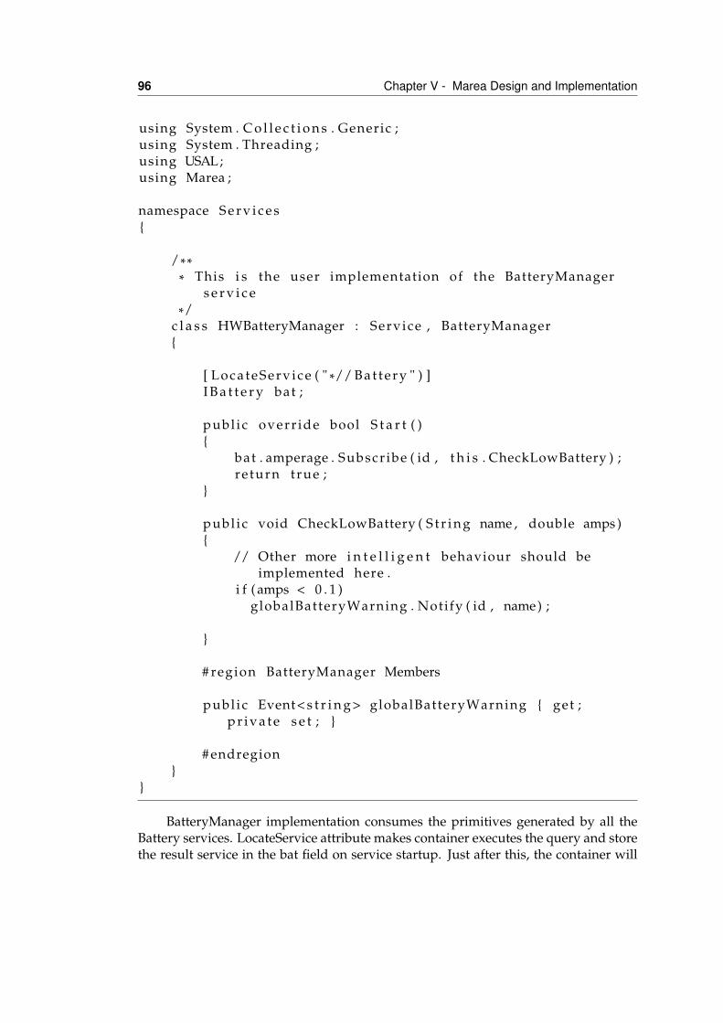
96 Chapter V - Marea Design and Implementation
using System . C o l l e c t i o n s . Generic ;using System . Threading ;using USAL;using Marea ;
namespace S e r v i c e s{
/*** This i s the user implementation of the BatteryManager
s e r v i c e*/
c l a s s HWBatteryManager : Service , BatteryManager{
[ LocateServ ice ( " *// B a t t e r y " ) ]I B a t t e r y bat ;
publ ic overr ide bool S t a r t ( ){
bat . amperage . Subscr ibe ( id , t h i s . CheckLowBattery ) ;re turn true ;
}
publ ic void CheckLowBattery ( S t r i n g name , double amps ){
// Other more i n t e l l i g e n t behaviour should beimplemented here .
i f ( amps < 0 . 1 )globalBatteryWarning . Notify ( id , name) ;
}
# region BatteryManager Members
publ ic Event< s t r i n g > globalBatteryWarning { get ;p r i v a t e s e t ; }
# endregion}
}
BatteryManager implementation consumes the primitives generated by all theBattery services. LocateService attribute makes container executes the query and storethe result service in the bat field on service startup. Just after this, the container will
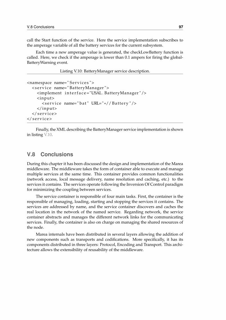
V.8 Conclusions 97
call the Start function of the service. Here the service implementation subscribes tothe amperage variable of all the battery services for the current subsystem.
Each time a new amperage value is generated, the checkLowBattery function iscalled. Here, we check if the amperage is lower than 0.1 ampers for firing the global-BatteryWarning event.
Listing V.10: BatteryManager service description.
<namespace name=" S e r v i c e s ">< s e r v i c e name=" BatteryManager ">
<implement i n t e r f a c e ="USAL. BatteryManager "/><input>
< s e r v i c e name=" bat " URL=" *// B a t t e r y "/></input>
</ s e r v i c e ></ s e r v i c e >
Finally, the XML describing the BatteryManager service implementation is shownin listing V.10.
V.8 ConclusionsDuring this chapter it has been discussed the design and implementation of the Mareamiddleware. The middleware takes the form of container able to execute and managemultiple services at the same time. This container provides common functionalities(network access, local message delivery, name resolution and caching, etc.) to theservices it contains. The services operate following the Inversion Of Control paradigmfor minimizing the coupling between services.
The service container is responsible of four main tasks. First, the container is theresponsible of managing, loading, starting and stopping the services it contains. Theservices are addressed by name, and the service container discovers and caches thereal location in the network of the named service. Regarding network, the servicecontainer abstracts and manages the different network links for the communicatingservices. Finally, the container is also on charge on managing the shared resources ofthe node.
Marea internals have been distributed in several layers allowing the addition ofnew components such as transports and codifications. More specifically, it has itscomponents distributed in three layers: Protocol, Encoding and Transport. This archi-tecture allows the extensibility of reusability of the middleware.

VIStartup mechanisms
VI.1 IntroductionThe service-oriented architecture and abstraction layer presented in the previouschapters can be seen as a modular avionics architecture for UAS. To be operative,the architecture definition and the abstraction layer also need a definition of the op-erations and procedures to convert a set of “standardized” services into a flyable andoperational system. This chapter will detail the configuration and deployment infras-tructure and its related procedures that complete our vision of UAS avionics. The fullprocess has been divided into two steps: dispatching and startup.
Dispatching involves all the configuration steps, including selecting the aircraftand the payload, defining the mission and the flight plan and cross-checking all the in-terdependencies and restrictions between these items. The output is a mission descrip-tion file, which includes the annotated flight plan, the required payload, the USALservices and their configuration. The next step, startup, involves allocating the ser-vices to the selected hardware and, finally, deploying all the software services andtheir associated files to the assigned nodes.
Thus, we can divide the full functionality into a first part that is specific to UAS
99
100 Chapter VI - Startup mechanisms
missions and avionics, and a second part that is independent of the application anduseful for any distributed embedded application.
VI.2 DispatchingIn civil aviation, a set of procedures and standardized practices are followed to oper-ate all kinds of aircraft safely, efficiently and regularly. Safe operating practice criteriacan be found in ICAO Appendix 6, Part I (?) for commercial air transport operators,while Part II and Part III of the same Appendix deal with general aviation and heli-copter operations respectively. These standards and recommended practices includewhat kind of documentation an operator should provide for the flight crew, and whatthe responsibilities and duties of the pilot-in-command are before, during and after aflight, among other information.
The flight operations officer, also known as the flight dispatcher, is one of the keyactors during aircraft operations and shares duties and responsibilities with the pilot-in-command. Flight dispatchers assist pilot-in-commands with all tasks related toflight preparation, such as aircraft load planning, meteorological briefing, operationaland Air Traffic Services flight planning etc. During a flight, the flight dispatchers arein close contact with aircraft crew and provide all kinds of information. In the eventof an emergency, they initiate the procedures outlined in the operations manual incoordination with the pilot-in-command.
In this context, a flight dispatcher must be familiar with:
• The contents of the operations manual
• The radio equipment used in the airplanes
• The navigation equipment used in the airplanes
• The seasonal meteorological conditions and the sources of meteorological infor-mation
• The effects of meteorological conditions on radio reception in the airplanes
• The features and limitations of each navigation system used in the operation
• The airplane loading instructions
The flight operations officer and the pilot-in-command are jointly responsible for ver-ifying prior to the flight that:
• The airplane is airworthy
• The instruments and equipment for the particular type of operation are installedand are sufficient for the flight
VI.2 Dispatching 101
• A maintenance release as prescribed has been issued for the airplane
• The mass of the airplane and center of gravity location are such that the flightcan be conducted safely, taking into account the expected flight conditions
• Any load carried is properly distributed and safely secured
• Checks have been carried out to ensure that the operating limitations can becomplied with for the flight
• The standards relating to operational flight planning have been complied with
Currently, most UAVs are designed for military purposes. Very few civil applicationshave been developed, mainly because of the lack of regulations on UAV certification,airworthiness and operations. Therefore, UAV operations have always been highlydependent on the mission to be accomplished and on the flight scenario. The develop-ment of more general UAV applications is still limited by the absence of systems thatsupport the undertaking of the actual mission. UAV developers must devise specificsystems to control the desired flight profile, the sensor activation and configurationthroughout the flight, data storage and data transmission to ground control. All theseelements may delay and increase the risk and cost of the project. If realistic missionsare to be developed, additional, effective system support must be available, so thatflexible and adaptable platforms can be provided for any application that is likely touse them.
A flexible and reusable hardware/software architecture that is designed to facil-itate the development of UAV-based missions has been introduced in previous chap-ters(?). A distributed embedded system is built over a set of embedded microproces-sors (in both the UAV and the ground control station) and connected by a local areanetwork. Then, applications are developed following a service/subscription-basedsoftware architecture. Each computation module may support multiple applications.Each application could create and subscribe to available services. Services could bediscovered and consumed in a dynamic way, such as web services in the Internet do-main. Applications could interchange information transparently from the networktopology, the application implementation and the actual data payload.
This flexibility is organized into a user-parameterizable UAV Service AbstractionLayer (USAL). The USAL defines a collection of standard services and their interrela-tions as a basic starting point for further development by users. Functionalities areoffered such as enhanced flight plans, a mission control engine, data storage and com-munications management. Additional services can be included according to require-ments, but all existing services and inter-service communication infrastructure can beexploited and tailored to specific needs. This approach reduces development timesand risks, and at the same time gives the user more flexibility and enables more ambi-tious applications to be developed.
This section presents the design of a new dispatching methodology for UAV civilapplications that assists UAV operations following the same philosophy as the flight
102 Chapter VI - Startup mechanisms
dispatching practices used in civil aviation. However, due to the singularities of UAVsystems, flight dispatching is merged with pilot-in-command duties and mission anal-ysis and operation, i.e. mission dispatching.
The overall process is mission-centric. It focuses on all the requirements neededto properly implement the assigned tasks, but also integrates the traditional dispatch-ing requirements. The proposed dispatching process is built on the USAL and Mareaarchitecture. Based on this architecture, a methodology is introduced to characterize:
• The UAV mission: its objectives, payload requirements, operation, flight plan,etc.
• The UAV airframe: its various characteristics, performance, the USAL servicesrequired to manage the flight and the mission, available payload bays, fuel andelectrical architecture.
• Required sensors and other payload, etc.
All these elements are combined in an iterative dispatching flow. On the basis of themission objectives, a UAV has to be selected that initially fits the mission requirements.Subsequently, the overall set of services required to implement the mission, and alltypes of payload (communication, computation, sensors, batteries, etc.) have to beselected. Then, the payload has to be organized in the airframe, services assigned tocomputation payload modules, and the initial flight plan template instantiated into anoperative one.
The result of the process is the actual UAV configuration in terms of fuel, electricalsystem, payload configuration, flight plan, etc.; the operational flight plan, alternativeroutes and landing sites in case of derouting and/or emergencies; the detailed Mareaservice architecture; how services are assigned to payload modules; and even the setof rules and system reactions that define the contingency planning.
VI.2.1 Overview of the Dispatching ProcessThe mission dispatching proposed in this thesis follows the classical V-shaped processdepicted in Figure VI-1. It works on four conceptual levels: mission, airframe, USALservices and finally the payload and evolves from general mission requirements to aprecise UAV configuration.
All of the elements required for the dispatching process need to be previouslycharacterized in terms of a predefined classification scheme. Thus, the mission re-quirements, the suggested flight plan, all the characteristics of the UAV airframe, thepayload elements, the USAL service modules, etc; are characterized using XML pat-terns that describe their requirements, characteristics, configurations, dependencies,etc.
When a mission dispatching process is started, a specific database is created. In-formation is added to this database and cross-checked to ensure that requirements and
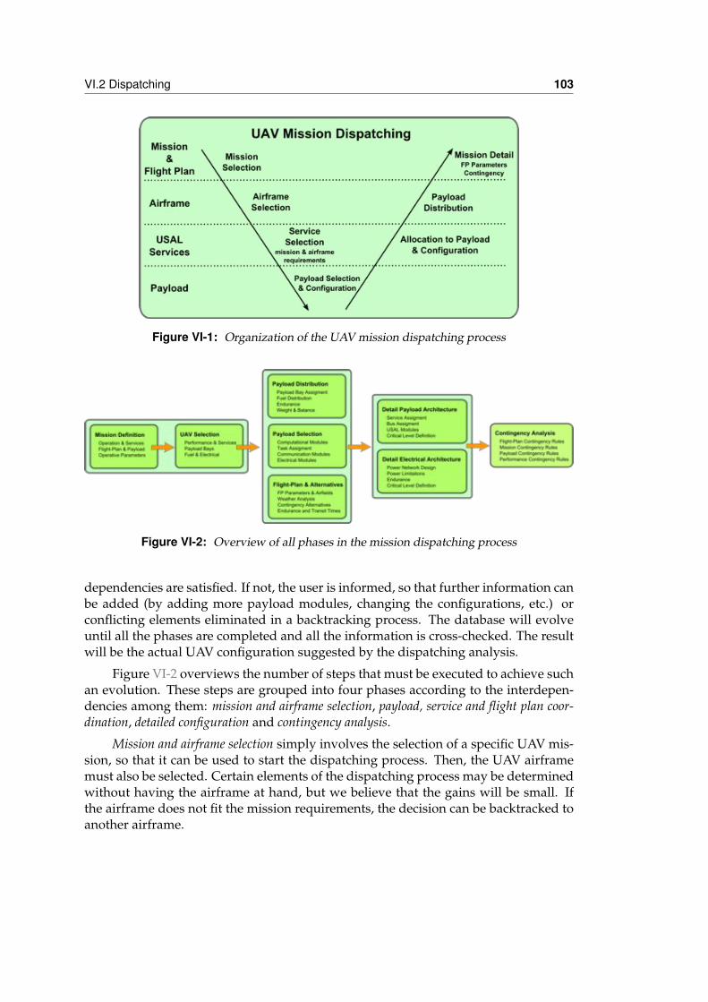
VI.2 Dispatching 103
Figure VI-1: Organization of the UAV mission dispatching process
Figure VI-2: Overview of all phases in the mission dispatching process
dependencies are satisfied. If not, the user is informed, so that further information canbe added (by adding more payload modules, changing the configurations, etc.) orconflicting elements eliminated in a backtracking process. The database will evolveuntil all the phases are completed and all the information is cross-checked. The resultwill be the actual UAV configuration suggested by the dispatching analysis.
Figure VI-2 overviews the number of steps that must be executed to achieve suchan evolution. These steps are grouped into four phases according to the interdepen-dencies among them: mission and airframe selection, payload, service and flight plan coor-dination, detailed configuration and contingency analysis.
Mission and airframe selection simply involves the selection of a specific UAV mis-sion, so that it can be used to start the dispatching process. Then, the UAV airframemust also be selected. Certain elements of the dispatching process may be determinedwithout having the airframe at hand, but we believe that the gains will be small. Ifthe airframe does not fit the mission requirements, the decision can be backtracked toanother airframe.
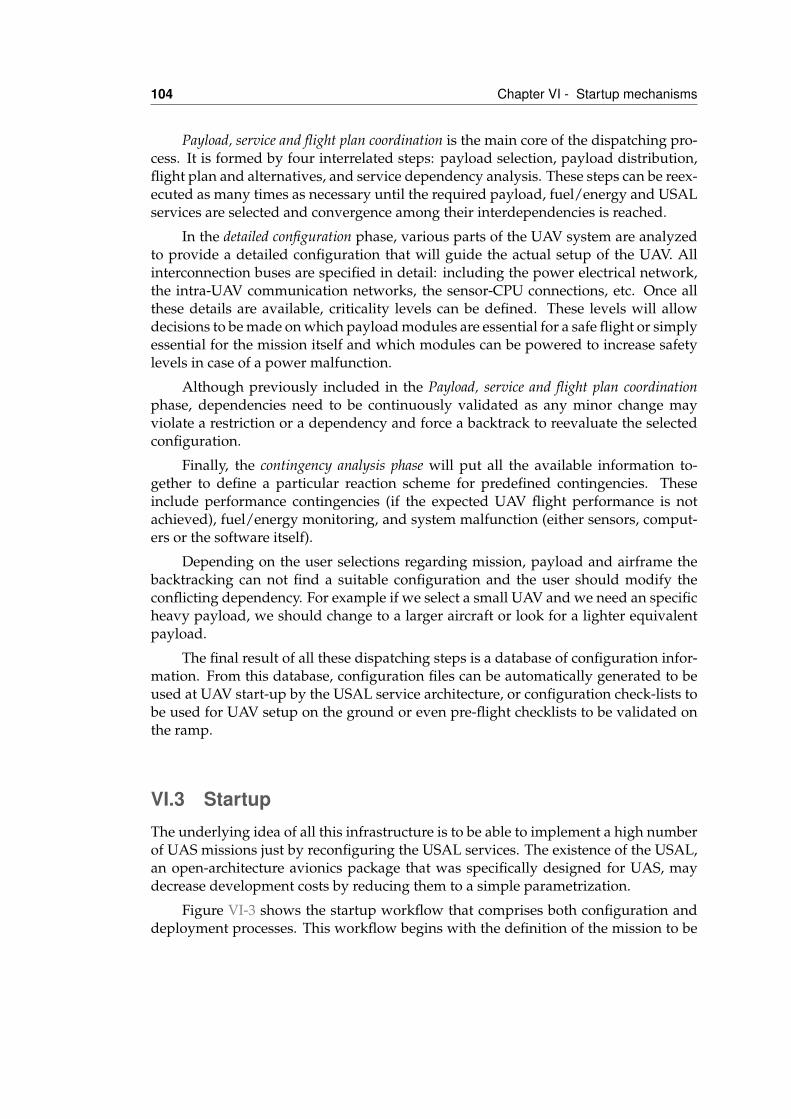
104 Chapter VI - Startup mechanisms
Payload, service and flight plan coordination is the main core of the dispatching pro-cess. It is formed by four interrelated steps: payload selection, payload distribution,flight plan and alternatives, and service dependency analysis. These steps can be reex-ecuted as many times as necessary until the required payload, fuel/energy and USALservices are selected and convergence among their interdependencies is reached.
In the detailed configuration phase, various parts of the UAV system are analyzedto provide a detailed configuration that will guide the actual setup of the UAV. Allinterconnection buses are specified in detail: including the power electrical network,the intra-UAV communication networks, the sensor-CPU connections, etc. Once allthese details are available, criticality levels can be defined. These levels will allowdecisions to be made on which payload modules are essential for a safe flight or simplyessential for the mission itself and which modules can be powered to increase safetylevels in case of a power malfunction.
Although previously included in the Payload, service and flight plan coordinationphase, dependencies need to be continuously validated as any minor change mayviolate a restriction or a dependency and force a backtrack to reevaluate the selectedconfiguration.
Finally, the contingency analysis phase will put all the available information to-gether to define a particular reaction scheme for predefined contingencies. Theseinclude performance contingencies (if the expected UAV flight performance is notachieved), fuel/energy monitoring, and system malfunction (either sensors, comput-ers or the software itself).
Depending on the user selections regarding mission, payload and airframe thebacktracking can not find a suitable configuration and the user should modify theconflicting dependency. For example if we select a small UAV and we need an specificheavy payload, we should change to a larger aircraft or look for a lighter equivalentpayload.
The final result of all these dispatching steps is a database of configuration infor-mation. From this database, configuration files can be automatically generated to beused at UAV start-up by the USAL service architecture, or configuration check-lists tobe used for UAV setup on the ground or even pre-flight checklists to be validated onthe ramp.
VI.3 StartupThe underlying idea of all this infrastructure is to be able to implement a high numberof UAS missions just by reconfiguring the USAL services. The existence of the USAL,an open-architecture avionics package that was specifically designed for UAS, maydecrease development costs by reducing them to a simple parametrization.
Figure VI-3 shows the startup workflow that comprises both configuration anddeployment processes. This workflow begins with the definition of the mission to be
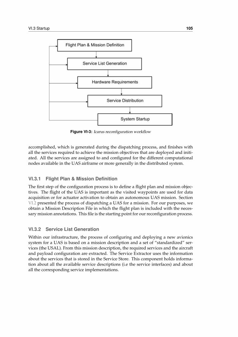
VI.3 Startup 105
Figure VI-3: Icarus reconfiguration workflow
accomplished, which is generated during the dispatching process, and finishes withall the services required to achieve the mission objectives that are deployed and initi-ated. All the services are assigned to and configured for the different computationalnodes available in the UAS airframe or more generally in the distributed system.
VI.3.1 Flight Plan & Mission DefinitionThe first step of the configuration process is to define a flight plan and mission objec-tives. The flight of the UAS is important as the visited waypoints are used for dataacquisition or for actuator activation to obtain an autonomous UAS mission. SectionVI.2 presented the process of dispatching a UAS for a mission. For our purposes, weobtain a Mission Description File in which the flight plan is included with the neces-sary mission annotations. This file is the starting point for our reconfiguration process.
VI.3.2 Service List GenerationWithin our infrastructure, the process of configuring and deploying a new avionicssystem for a UAS is based on a mission description and a set of “standardized” ser-vices (the USAL). From this mission description, the required services and the aircraftand payload configuration are extracted. The Service Extractor uses the informationabout the services that is stored in the Service Store. This component holds informa-tion about all the available service descriptions (i.e the service interfaces) and aboutall the corresponding service implementations.
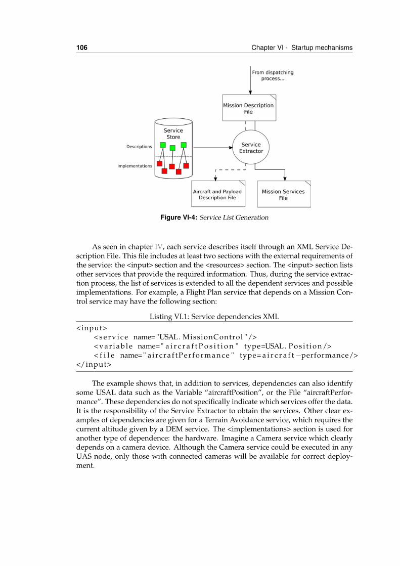
106 Chapter VI - Startup mechanisms
Figure VI-4: Service List Generation
As seen in chapter IV, each service describes itself through an XML Service De-scription File. This file includes at least two sections with the external requirements ofthe service: the <input> section and the <resources> section. The <input> section listsother services that provide the required information. Thus, during the service extrac-tion process, the list of services is extended to all the dependent services and possibleimplementations. For example, a Flight Plan service that depends on a Mission Con-trol service may have the following section:
Listing VI.1: Service dependencies XML<input>
< s e r v i c e name="USAL. MissionControl "/>< v a r i a b l e name=" a i r c r a f t P o s i t i o n " type=USAL. P o s i t i o n />< f i l e name=" a i r c r a f t P e r f o r m a n c e " type= a i r c r a f t −performance/>
</input>
The example shows that, in addition to services, dependencies can also identifysome USAL data such as the Variable “aircraftPosition”, or the File “aircraftPerfor-mance”. These dependencies do not specifically indicate which services offer the data.It is the responsibility of the Service Extractor to obtain the services. Other clear ex-amples of dependencies are given for a Terrain Avoidance service, which requires thecurrent altitude given by a DEM service. The <implementations> section is used foranother type of dependence: the hardware. Imagine a Camera service which clearlydepends on a camera device. Although the Camera service could be executed in anyUAS node, only those with connected cameras will be available for correct deploy-ment.
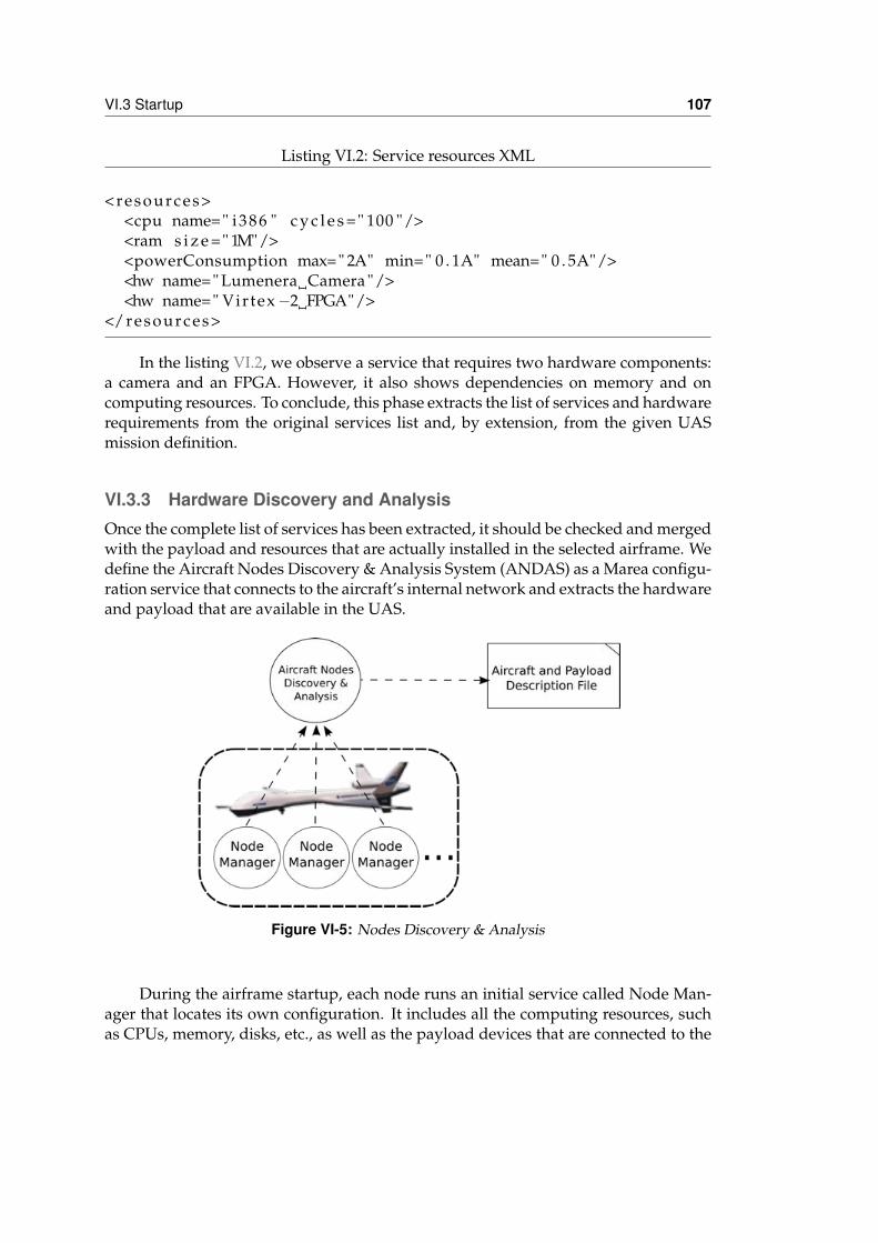
VI.3 Startup 107
Listing VI.2: Service resources XML
<resources><cpu name=" i386 " c y c l e s =" 100 "/><ram s i z e =" 1M"/><powerConsumption max=" 2A" min=" 0 . 1A" mean=" 0 . 5A"/><hw name=" Lumenera Camera "/><hw name=" Virtex −2 FPGA"/>
</resources>
In the listing VI.2, we observe a service that requires two hardware components:a camera and an FPGA. However, it also shows dependencies on memory and oncomputing resources. To conclude, this phase extracts the list of services and hardwarerequirements from the original services list and, by extension, from the given UASmission definition.
VI.3.3 Hardware Discovery and AnalysisOnce the complete list of services has been extracted, it should be checked and mergedwith the payload and resources that are actually installed in the selected airframe. Wedefine the Aircraft Nodes Discovery & Analysis System (ANDAS) as a Marea configu-ration service that connects to the aircraft’s internal network and extracts the hardwareand payload that are available in the UAS.
Figure VI-5: Nodes Discovery & Analysis
During the airframe startup, each node runs an initial service called Node Man-ager that locates its own configuration. It includes all the computing resources, suchas CPUs, memory, disks, etc., as well as the payload devices that are connected to the
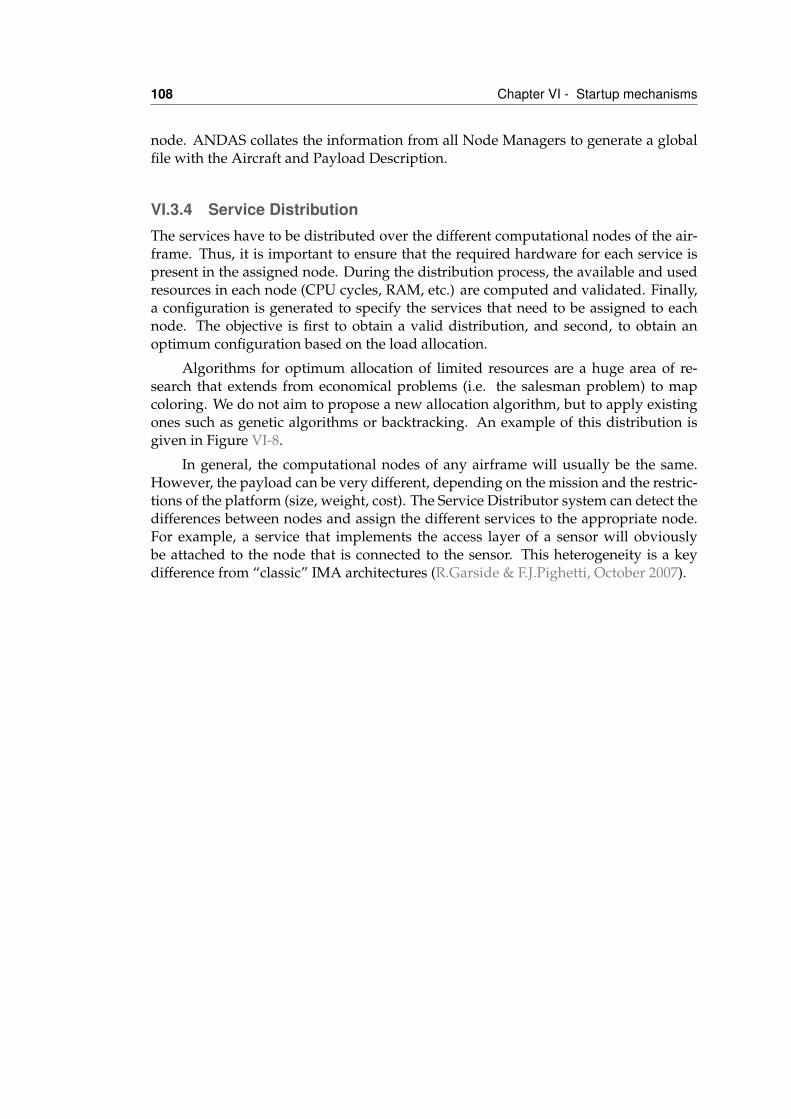
108 Chapter VI - Startup mechanisms
node. ANDAS collates the information from all Node Managers to generate a globalfile with the Aircraft and Payload Description.
VI.3.4 Service DistributionThe services have to be distributed over the different computational nodes of the air-frame. Thus, it is important to ensure that the required hardware for each service ispresent in the assigned node. During the distribution process, the available and usedresources in each node (CPU cycles, RAM, etc.) are computed and validated. Finally,a configuration is generated to specify the services that need to be assigned to eachnode. The objective is first to obtain a valid distribution, and second, to obtain anoptimum configuration based on the load allocation.
Algorithms for optimum allocation of limited resources are a huge area of re-search that extends from economical problems (i.e. the salesman problem) to mapcoloring. We do not aim to propose a new allocation algorithm, but to apply existingones such as genetic algorithms or backtracking. An example of this distribution isgiven in Figure VI-8.
In general, the computational nodes of any airframe will usually be the same.However, the payload can be very different, depending on the mission and the restric-tions of the platform (size, weight, cost). The Service Distributor system can detect thedifferences between nodes and assign the different services to the appropriate node.For example, a service that implements the access layer of a sensor will obviouslybe attached to the node that is connected to the sensor. This heterogeneity is a keydifference from “classic” IMA architectures (R.Garside & F.J.Pighetti, October 2007).
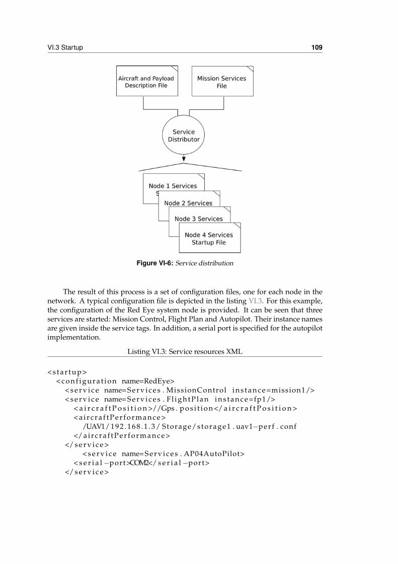
VI.3 Startup 109
Figure VI-6: Service distribution
The result of this process is a set of configuration files, one for each node in thenetwork. A typical configuration file is depicted in the listing VI.3. For this example,the configuration of the Red Eye system node is provided. It can be seen that threeservices are started: Mission Control, Flight Plan and Autopilot. Their instance namesare given inside the service tags. In addition, a serial port is specified for the autopilotimplementation.
Listing VI.3: Service resources XML
< s t a r t u p>< c o n f i g u r a t i o n name=RedEye>
< s e r v i c e name= S e r v i c e s . MissionControl i n s t a n c e =mission1/>< s e r v i c e name= S e r v i c e s . F l i g h t P l a n i n s t a n c e =fp1/>
< a i r c r a f t P o s i t i o n >//Gps . p o s i t i o n </ a i r c r a f t P o s i t i o n >< a i r c r a f t P e r f o r m a n c e>
/UAV1/ 1 9 2 . 1 6 8 . 1 . 3 / Storage/storage1 . uav1−perf . conf</ a i r c r a f t P e r f o r m a n c e>
</ s e r v i c e >< s e r v i c e name= S e r v i c e s . AP04AutoPilot>
< s e r i a l −port>COM2</ s e r i a l −port></ s e r v i c e >
110 Chapter VI - Startup mechanisms
</ c o n f i g u r a t i o n ></s t a r t u p>
Below is the syntax for these startup XML files:
startup This is the main tag for the startup file.
configuration Several configurations can be provided for easy reconfiguration. Forexample, the startup file can have standard and debug configurations for test-ing, or configurations for different missions. If not otherwise specified, Mareaautomatically starts the first configuration.
service Each configuration declares all the service that have to be started by Marea.The service to be started is indicated with a service tag.
• name This is the name of the service implementation to be started.
• instance As multiple services of the same class can be started, they can also beidentified with an instance name. This information is propagated to the namingsystem so that services can be located by their instance name.
• Additional implementation-specific information can be provided inside the ser-vice tag. This information will be gathered in a dictionary-like data structureand made available for the service implementation.
VI.3.5 Services deployment and StartupThe Node Manager service presented above has two other important functions: ser-vices deployment and initiation. On startup, it contacts the Startup Manager to receiveits assigned configuration. This contact is usually made via one of the ground team’sexternal laptops that is connected to the onboard Marea network. Using the receivedservice distribution file, which includes all the services to be loaded to each node andall the additional data files that are needed, the Node Manager checks whether theservice code is allocated to the node and, if not, requests it from an external ServiceStore service. As seen in chapter V, the service executables and additional data arepackaged in deployment units. The file distribution of deployment units is efficientlyprovided by the underlying middleware, using its multicast file transfer. If more thanone node needs the same deployment unit, then the corresponding file can be sent si-multaneously to multiple nodes. Then, each Node Manager is responsible for startingall its services. Finally, the Deploy and Startup Manager is notified about the correctfinalization and the UAS can proceed to pre-flight checking and flight. In case of fail-ure, the process is restarted at some previous phase to allow the maintenance team tosolve detected problems.
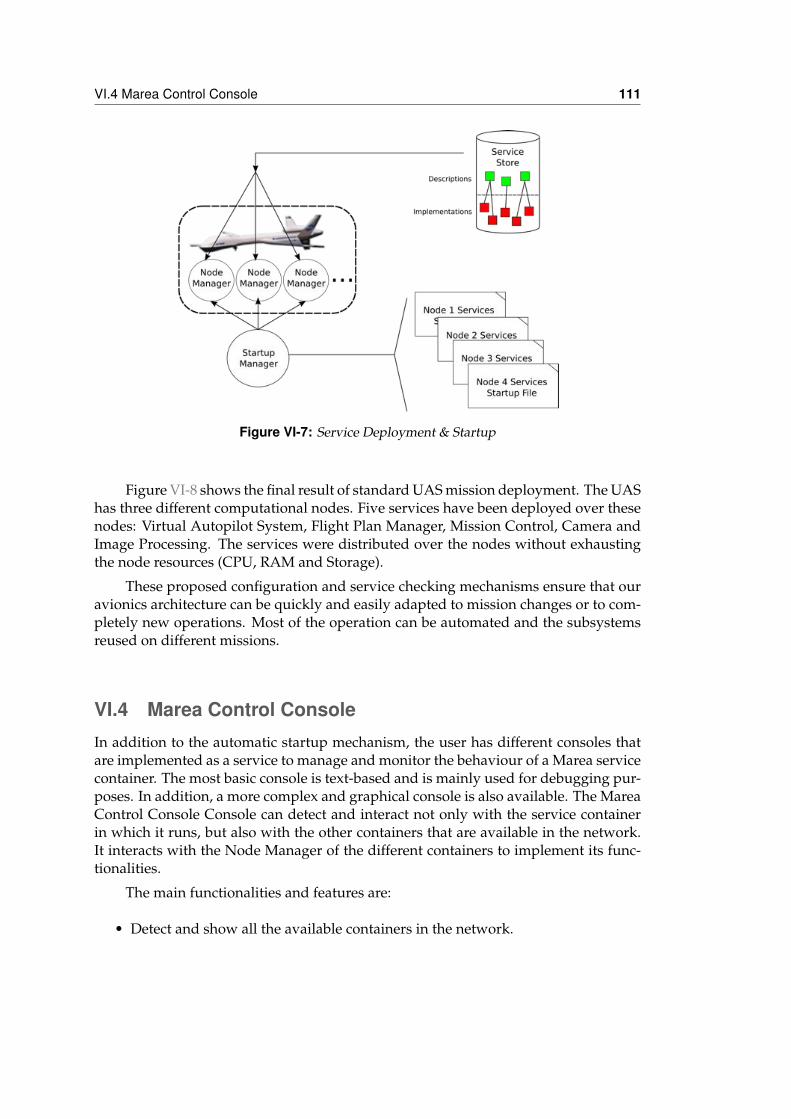
VI.4 Marea Control Console 111
Figure VI-7: Service Deployment & Startup
Figure VI-8 shows the final result of standard UAS mission deployment. The UAShas three different computational nodes. Five services have been deployed over thesenodes: Virtual Autopilot System, Flight Plan Manager, Mission Control, Camera andImage Processing. The services were distributed over the nodes without exhaustingthe node resources (CPU, RAM and Storage).
These proposed configuration and service checking mechanisms ensure that ouravionics architecture can be quickly and easily adapted to mission changes or to com-pletely new operations. Most of the operation can be automated and the subsystemsreused on different missions.
VI.4 Marea Control ConsoleIn addition to the automatic startup mechanism, the user has different consoles thatare implemented as a service to manage and monitor the behaviour of a Marea servicecontainer. The most basic console is text-based and is mainly used for debugging pur-poses. In addition, a more complex and graphical console is also available. The MareaControl Console Console can detect and interact not only with the service containerin which it runs, but also with the other containers that are available in the network.It interacts with the Node Manager of the different containers to implement its func-tionalities.
The main functionalities and features are:
• Detect and show all the available containers in the network.
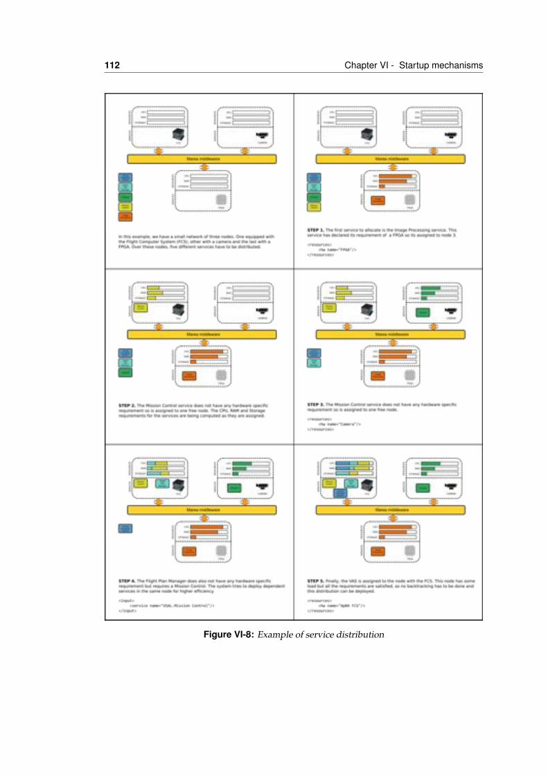
112 Chapter VI - Startup mechanisms
Figure VI-8: Example of service distribution
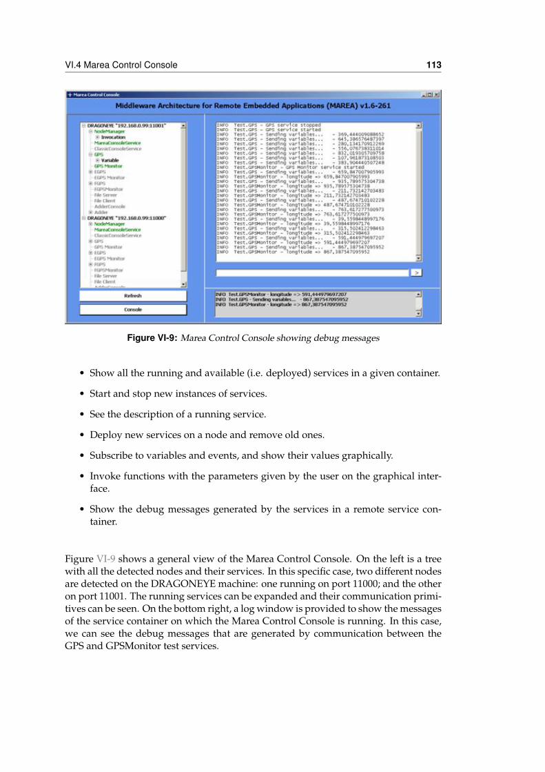
VI.4 Marea Control Console 113
Figure VI-9: Marea Control Console showing debug messages
• Show all the running and available (i.e. deployed) services in a given container.
• Start and stop new instances of services.
• See the description of a running service.
• Deploy new services on a node and remove old ones.
• Subscribe to variables and events, and show their values graphically.
• Invoke functions with the parameters given by the user on the graphical inter-face.
• Show the debug messages generated by the services in a remote service con-tainer.
Figure VI-9 shows a general view of the Marea Control Console. On the left is a treewith all the detected nodes and their services. In this specific case, two different nodesare detected on the DRAGONEYE machine: one running on port 11000; and the otheron port 11001. The running services can be expanded and their communication primi-tives can be seen. On the bottom right, a log window is provided to show the messagesof the service container on which the Marea Control Console is running. In this case,we can see the debug messages that are generated by communication between theGPS and GPSMonitor test services.
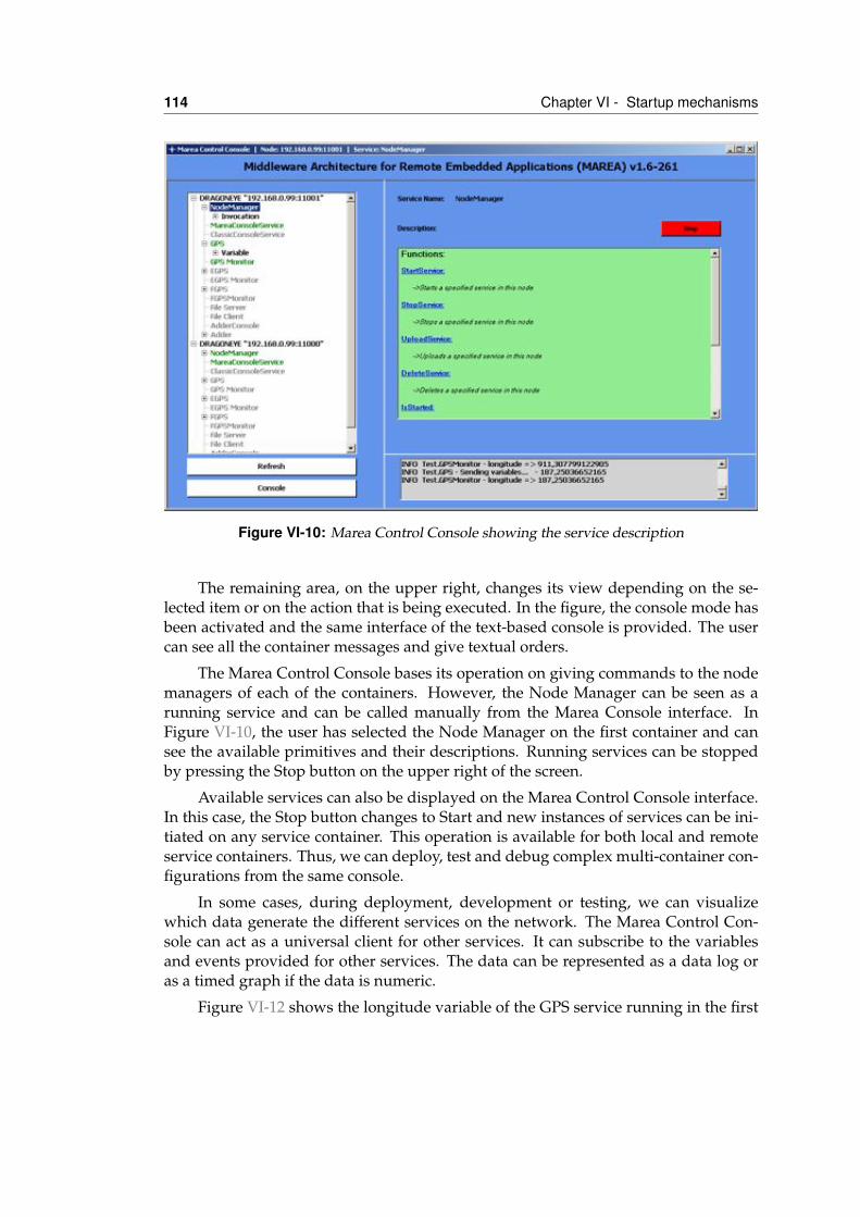
114 Chapter VI - Startup mechanisms
Figure VI-10: Marea Control Console showing the service description
The remaining area, on the upper right, changes its view depending on the se-lected item or on the action that is being executed. In the figure, the console mode hasbeen activated and the same interface of the text-based console is provided. The usercan see all the container messages and give textual orders.
The Marea Control Console bases its operation on giving commands to the nodemanagers of each of the containers. However, the Node Manager can be seen as arunning service and can be called manually from the Marea Console interface. InFigure VI-10, the user has selected the Node Manager on the first container and cansee the available primitives and their descriptions. Running services can be stoppedby pressing the Stop button on the upper right of the screen.
Available services can also be displayed on the Marea Control Console interface.In this case, the Stop button changes to Start and new instances of services can be ini-tiated on any service container. This operation is available for both local and remoteservice containers. Thus, we can deploy, test and debug complex multi-container con-figurations from the same console.
In some cases, during deployment, development or testing, we can visualizewhich data generate the different services on the network. The Marea Control Con-sole can act as a universal client for other services. It can subscribe to the variablesand events provided for other services. The data can be represented as a data log oras a timed graph if the data is numeric.
Figure VI-12 shows the longitude variable of the GPS service running in the first
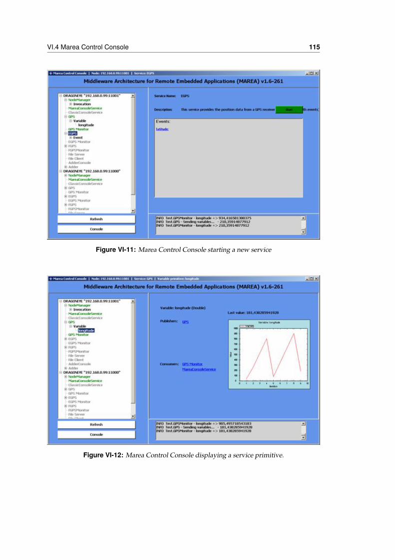
VI.4 Marea Control Console 115
Figure VI-11: Marea Control Console starting a new service
Figure VI-12: Marea Control Console displaying a service primitive.
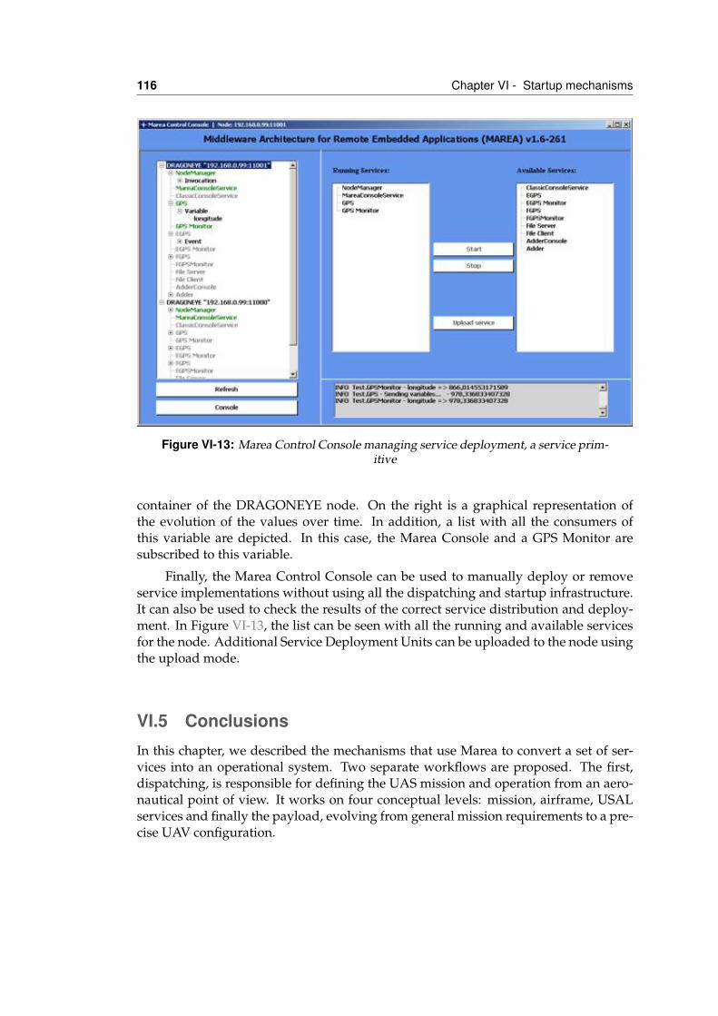
116 Chapter VI - Startup mechanisms
Figure VI-13: Marea Control Console managing service deployment, a service prim-itive
container of the DRAGONEYE node. On the right is a graphical representation ofthe evolution of the values over time. In addition, a list with all the consumers ofthis variable are depicted. In this case, the Marea Console and a GPS Monitor aresubscribed to this variable.
Finally, the Marea Control Console can be used to manually deploy or removeservice implementations without using all the dispatching and startup infrastructure.It can also be used to check the results of the correct service distribution and deploy-ment. In Figure VI-13, the list can be seen with all the running and available servicesfor the node. Additional Service Deployment Units can be uploaded to the node usingthe upload mode.
VI.5 ConclusionsIn this chapter, we described the mechanisms that use Marea to convert a set of ser-vices into an operational system. Two separate workflows are proposed. The first,dispatching, is responsible for defining the UAS mission and operation from an aero-nautical point of view. It works on four conceptual levels: mission, airframe, USALservices and finally the payload, evolving from general mission requirements to a pre-cise UAV configuration.
VI.5 Conclusions 117
The second workflow, startup, involves allocating, configuring, and starting therequired services in the available nodes. This process is generic to multiple embeddedapplications. Figure VI-14 shows the full startup workflow, from the mission descrip-tion file that is generated in the dispatching process to the services that run in thenodes inside the UAV airframe.
At the top of the figure, the Service Extractor captures the services that are neededdue to the mission description and combines these with the available service imple-mentations. The Service Store acts as a repository of service interface descriptions andimplementations. In addition to the services, it is important to know which nodes areavailable in the network. This aircraft and payload description can come from two dif-ferent sources: the dispatching process in which a specific aircraft and payload havebeen chosen; and the Aircraft Nodes Discovery and Analysis System (ANDAS). AN-DAS is a service that can be deployed in the airframe to discover and analyze all thenodes. The resulting information can be cross-checked with the expected configura-tion from the dispatching process.
In the middle of the figure, the Service Distributor processes the required servicesand available nodes as well as their dependencies. It also generates a set of configura-tion files, one for each node in the network. These files are then passed to the StartupManager, which passes them on to the corresponding nodes on startup. This informa-tion can also be propagated back to the dispatching process.
Inside the airframe, each node has its own Node Manager service that holds thenode’s general information. This information can be sent to other subscribing services,such as ANDAS, or can be received, i.e. during system startup each Node Managerobtains its configuration from the Startup Manager. Then, the node starts all the ser-vices that are present in its configuration. If the node does not have any requiredservice deployment units, the Service Store can provide them efficiently to multiplenodes at the same time.
Finally, a Marea Control Console can be used to debug, monitor or manuallydeploy services into specific nodes. Its capabilities have proved useful in both testingand debugging scenarios.
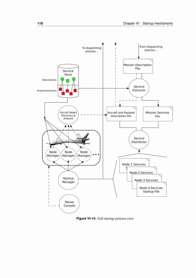
118 Chapter VI - Startup mechanisms
Figure VI-14: Full startup process view
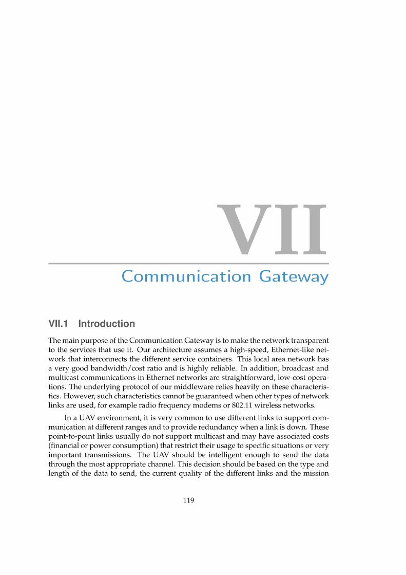
VIICommunication Gateway
VII.1 IntroductionThe main purpose of the Communication Gateway is to make the network transparentto the services that use it. Our architecture assumes a high-speed, Ethernet-like net-work that interconnects the different service containers. This local area network hasa very good bandwidth/cost ratio and is highly reliable. In addition, broadcast andmulticast communications in Ethernet networks are straightforward, low-cost opera-tions. The underlying protocol of our middleware relies heavily on these characteris-tics. However, such characteristics cannot be guaranteed when other types of networklinks are used, for example radio frequency modems or 802.11 wireless networks.
In a UAV environment, it is very common to use different links to support com-munication at different ranges and to provide redundancy when a link is down. Thesepoint-to-point links usually do not support multicast and may have associated costs(financial or power consumption) that restrict their usage to specific situations or veryimportant transmissions. The UAV should be intelligent enough to send the datathrough the most appropriate channel. This decision should be based on the type andlength of the data to send, the current quality of the different links and the mission
119
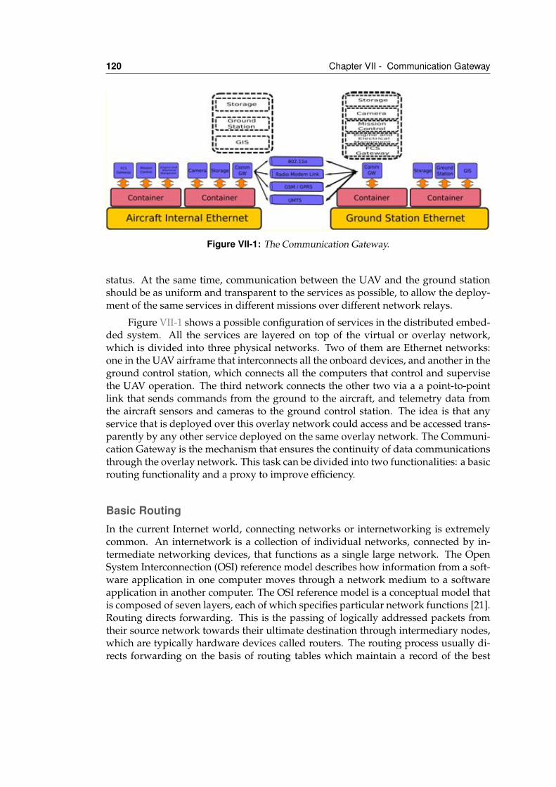
120 Chapter VII - Communication Gateway
Figure VII-1: The Communication Gateway.
status. At the same time, communication between the UAV and the ground stationshould be as uniform and transparent to the services as possible, to allow the deploy-ment of the same services in different missions over different network relays.
Figure VII-1 shows a possible configuration of services in the distributed embed-ded system. All the services are layered on top of the virtual or overlay network,which is divided into three physical networks. Two of them are Ethernet networks:one in the UAV airframe that interconnects all the onboard devices, and another in theground control station, which connects all the computers that control and supervisethe UAV operation. The third network connects the other two via a a point-to-pointlink that sends commands from the ground to the aircraft, and telemetry data fromthe aircraft sensors and cameras to the ground control station. The idea is that anyservice that is deployed over this overlay network could access and be accessed trans-parently by any other service deployed on the same overlay network. The Communi-cation Gateway is the mechanism that ensures the continuity of data communicationsthrough the overlay network. This task can be divided into two functionalities: a basicrouting functionality and a proxy to improve efficiency.
Basic RoutingIn the current Internet world, connecting networks or internetworking is extremelycommon. An internetwork is a collection of individual networks, connected by in-termediate networking devices, that functions as a single large network. The OpenSystem Interconnection (OSI) reference model describes how information from a soft-ware application in one computer moves through a network medium to a softwareapplication in another computer. The OSI reference model is a conceptual model thatis composed of seven layers, each of which specifies particular network functions [21].Routing directs forwarding. This is the passing of logically addressed packets fromtheir source network towards their ultimate destination through intermediary nodes,which are typically hardware devices called routers. The routing process usually di-rects forwarding on the basis of routing tables which maintain a record of the best
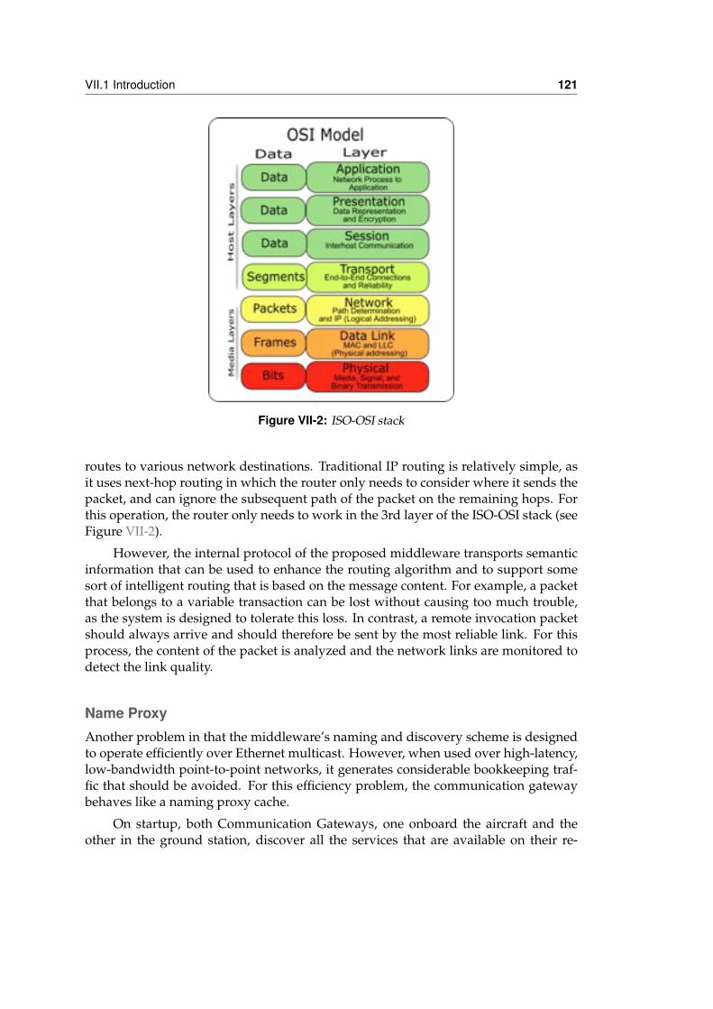
VII.1 Introduction 121
Figure VII-2: ISO-OSI stack
routes to various network destinations. Traditional IP routing is relatively simple, asit uses next-hop routing in which the router only needs to consider where it sends thepacket, and can ignore the subsequent path of the packet on the remaining hops. Forthis operation, the router only needs to work in the 3rd layer of the ISO-OSI stack (seeFigure VII-2).
However, the internal protocol of the proposed middleware transports semanticinformation that can be used to enhance the routing algorithm and to support somesort of intelligent routing that is based on the message content. For example, a packetthat belongs to a variable transaction can be lost without causing too much trouble,as the system is designed to tolerate this loss. In contrast, a remote invocation packetshould always arrive and should therefore be sent by the most reliable link. For thisprocess, the content of the packet is analyzed and the network links are monitored todetect the link quality.
Name ProxyAnother problem in that the middleware’s naming and discovery scheme is designedto operate efficiently over Ethernet multicast. However, when used over high-latency,low-bandwidth point-to-point networks, it generates considerable bookkeeping traf-fic that should be avoided. For this efficiency problem, the communication gatewaybehaves like a naming proxy cache.
On startup, both Communication Gateways, one onboard the aircraft and theother in the ground station, discover all the services that are available on their re-
122 Chapter VII - Communication Gateway
spective local networks. This information is packed and interchanged between them.Thus, the onboard Communication Gateway knows all the ground services and theirdescriptions, and vice versa.
At this point, the Communication Gateways publish the information as if theywere the providers of the variables, event, functions, etc. This operation virtuallycreates a series of proxy services on the same communication service. If a dynamicchange occurs, the Communication Gateways monitor the status of the services thatcan be accessed remotely. When a change is detected and the network status al-lows,the new condition is sent to the corresponding Communication Gateway, to up-date its proxy services. All the naming and discovering mechanisms are then per-formed by the communication gateway that operates as a proxy cache. Thus, the asso-ciated bookkeeping traffic is minimized. When a service communicates with these vir-tual services, the Communication Gateway proceeds intelligently by routing the mes-sage through the most convenient link. For example, it can send commands and re-quired results via a low-bandwidth satcomm and send the telemetry variables throughan unreliable but inexpensive radio modem link.
Figure VII-1 shows the complete Distributed Embedded System that comprisesboth the Aircraft Internal Network and the Ground Control Station. Communicationbetween these networks is carried out via several point-to-point links and managed bythe Communication Gateways. The figure also shows the virtual services provided bythe Communication Gateways to simulate the services that are available on the remotenetworks. The Gateways can be configured using an XML file that provides informa-tion on the traffic and connectivity in the network. This configuration can be used tooverride the services’ semantic information and adapt them to the current mission ornetwork infrastructure. Using this scheme, the services do not need to be modifiedfor the specific requirements or restrictions of a particular mission’s communicationtopology. The communication gateway can be instructed to perform some specificoperations on concrete communications.
Some data can be sent in a best-effort way, but a complete copy of this informationcan be stored in persistent storage for subsequent processing on the ground. Otherdata, for example images taken from the UAV platform, are needed on the groundas soon as possible, but a reasonable delay is tolerated if the link is down. In thiscase, the Communication Gateway will cooperate with the storage module and use itas a temporal buffer. When the network bandwidth is available, the communicationwill send blocks of the temporal buffer to the ground, where the corresponding gate-way will join the fragments. This transfer operation can be improved by, for example,compressing the resulting images before transmission. Finally, a practical operationis to keep a black box of some specific onboard data for safety or debugging pur-poses. These operations are completely transparent to the onboard services, but areperformed autonomously by the Communication Gateway.
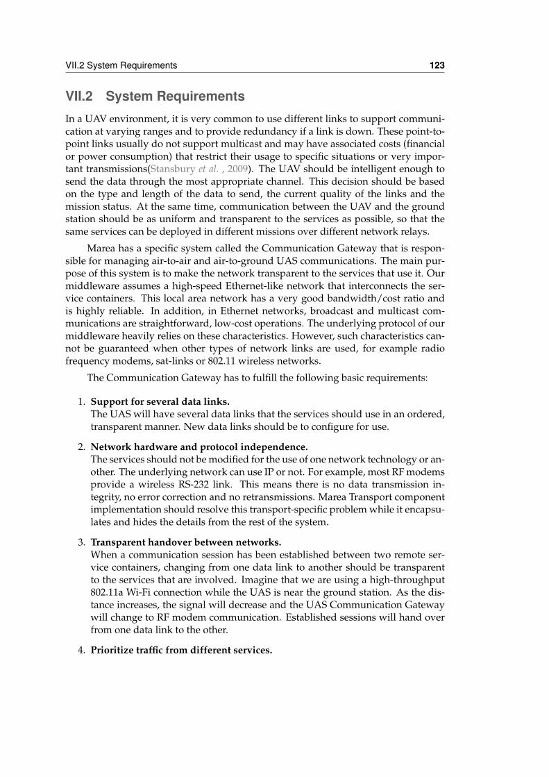
VII.2 System Requirements 123
VII.2 System RequirementsIn a UAV environment, it is very common to use different links to support communi-cation at varying ranges and to provide redundancy if a link is down. These point-to-point links usually do not support multicast and may have associated costs (financialor power consumption) that restrict their usage to specific situations or very impor-tant transmissions(Stansbury et al. , 2009). The UAV should be intelligent enough tosend the data through the most appropriate channel. This decision should be basedon the type and length of the data to send, the current quality of the links and themission status. At the same time, communication between the UAV and the groundstation should be as uniform and transparent to the services as possible, so that thesame services can be deployed in different missions over different network relays.
Marea has a specific system called the Communication Gateway that is respon-sible for managing air-to-air and air-to-ground UAS communications. The main pur-pose of this system is to make the network transparent to the services that use it. Ourmiddleware assumes a high-speed Ethernet-like network that interconnects the ser-vice containers. This local area network has a very good bandwidth/cost ratio andis highly reliable. In addition, in Ethernet networks, broadcast and multicast com-munications are straightforward, low-cost operations. The underlying protocol of ourmiddleware heavily relies on these characteristics. However, such characteristics can-not be guaranteed when other types of network links are used, for example radiofrequency modems, sat-links or 802.11 wireless networks.
The Communication Gateway has to fulfill the following basic requirements:
1. Support for several data links.The UAS will have several data links that the services should use in an ordered,transparent manner. New data links should be to configure for use.
2. Network hardware and protocol independence.The services should not be modified for the use of one network technology or an-other. The underlying network can use IP or not. For example, most RF modemsprovide a wireless RS-232 link. This means there is no data transmission in-tegrity, no error correction and no retransmissions. Marea Transport componentimplementation should resolve this transport-specific problem while it encapsu-lates and hides the details from the rest of the system.
3. Transparent handover between networks.When a communication session has been established between two remote ser-vice containers, changing from one data link to another should be transparentto the services that are involved. Imagine that we are using a high-throughput802.11a Wi-Fi connection while the UAS is near the ground station. As the dis-tance increases, the signal will decrease and the UAS Communication Gatewaywill change to RF modem communication. Established sessions will hand overfrom one data link to the other.
4. Prioritize traffic from different services.
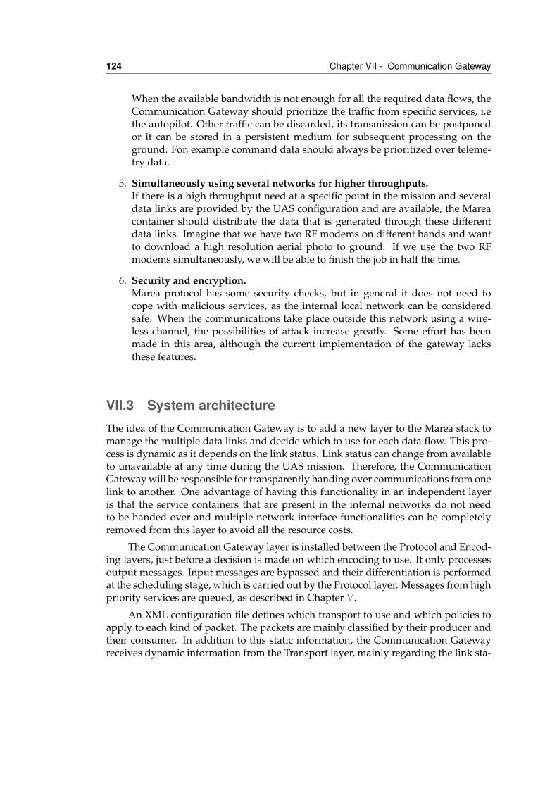
124 Chapter VII - Communication Gateway
When the available bandwidth is not enough for all the required data flows, theCommunication Gateway should prioritize the traffic from specific services, i.ethe autopilot. Other traffic can be discarded, its transmission can be postponedor it can be stored in a persistent medium for subsequent processing on theground. For, example command data should always be prioritized over teleme-try data.
5. Simultaneously using several networks for higher throughputs.If there is a high throughput need at a specific point in the mission and severaldata links are provided by the UAS configuration and are available, the Mareacontainer should distribute the data that is generated through these differentdata links. Imagine that we have two RF modems on different bands and wantto download a high resolution aerial photo to ground. If we use the two RFmodems simultaneously, we will be able to finish the job in half the time.
6. Security and encryption.Marea protocol has some security checks, but in general it does not need tocope with malicious services, as the internal local network can be consideredsafe. When the communications take place outside this network using a wire-less channel, the possibilities of attack increase greatly. Some effort has beenmade in this area, although the current implementation of the gateway lacksthese features.
VII.3 System architectureThe idea of the Communication Gateway is to add a new layer to the Marea stack tomanage the multiple data links and decide which to use for each data flow. This pro-cess is dynamic as it depends on the link status. Link status can change from availableto unavailable at any time during the UAS mission. Therefore, the CommunicationGateway will be responsible for transparently handing over communications from onelink to another. One advantage of having this functionality in an independent layeris that the service containers that are present in the internal networks do not needto be handed over and multiple network interface functionalities can be completelyremoved from this layer to avoid all the resource costs.
The Communication Gateway layer is installed between the Protocol and Encod-ing layers, just before a decision is made on which encoding to use. It only processesoutput messages. Input messages are bypassed and their differentiation is performedat the scheduling stage, which is carried out by the Protocol layer. Messages from highpriority services are queued, as described in Chapter V.
An XML configuration file defines which transport to use and which policies toapply to each kind of packet. The packets are mainly classified by their producer andtheir consumer. In addition to this static information, the Communication Gatewayreceives dynamic information from the Transport layer, mainly regarding the link sta-
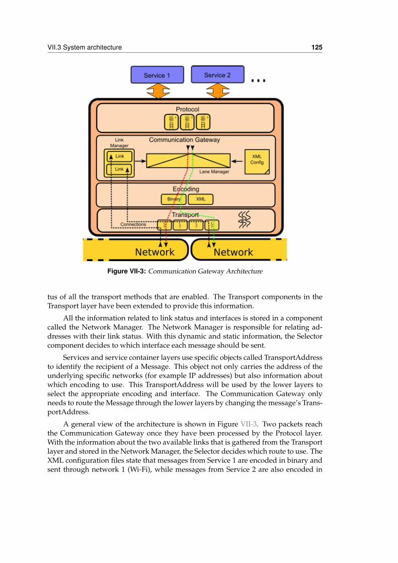
VII.3 System architecture 125
Figure VII-3: Communication Gateway Architecture
tus of all the transport methods that are enabled. The Transport components in theTransport layer have been extended to provide this information.
All the information related to link status and interfaces is stored in a componentcalled the Network Manager. The Network Manager is responsible for relating ad-dresses with their link status. With this dynamic and static information, the Selectorcomponent decides to which interface each message should be sent.
Services and service container layers use specific objects called TransportAddressto identify the recipient of a Message. This object not only carries the address of theunderlying specific networks (for example IP addresses) but also information aboutwhich encoding to use. This TransportAddress will be used by the lower layers toselect the appropriate encoding and interface. The Communication Gateway onlyneeds to route the Message through the lower layers by changing the message’s Trans-portAddress.
A general view of the architecture is shown in Figure VII-3. Two packets reachthe Communication Gateway once they have been processed by the Protocol layer.With the information about the two available links that is gathered from the Transportlayer and stored in the Network Manager, the Selector decides which route to use. TheXML configuration files state that messages from Service 1 are encoded in binary andsent through network 1 (Wi-Fi), while messages from Service 2 are also encoded in
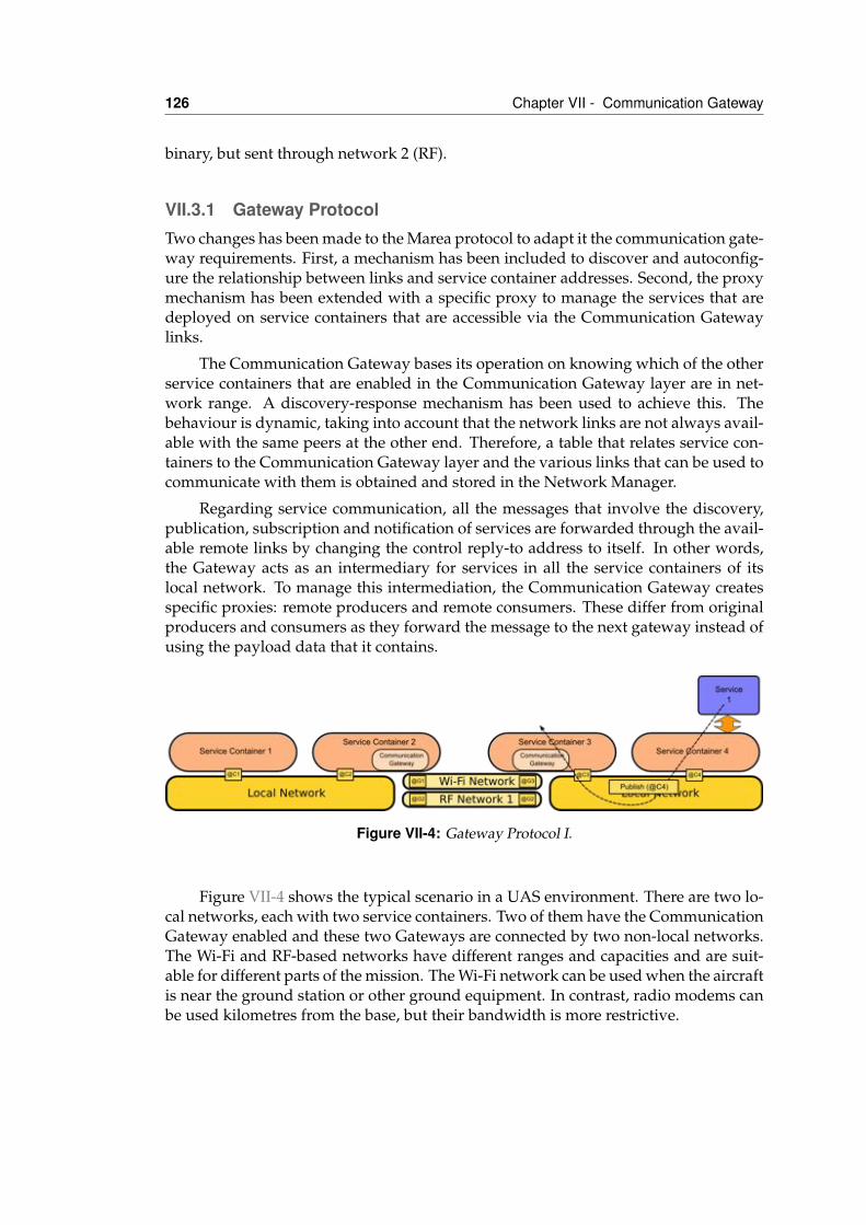
126 Chapter VII - Communication Gateway
binary, but sent through network 2 (RF).
VII.3.1 Gateway ProtocolTwo changes has been made to the Marea protocol to adapt it the communication gate-way requirements. First, a mechanism has been included to discover and autoconfig-ure the relationship between links and service container addresses. Second, the proxymechanism has been extended with a specific proxy to manage the services that aredeployed on service containers that are accessible via the Communication Gatewaylinks.
The Communication Gateway bases its operation on knowing which of the otherservice containers that are enabled in the Communication Gateway layer are in net-work range. A discovery-response mechanism has been used to achieve this. Thebehaviour is dynamic, taking into account that the network links are not always avail-able with the same peers at the other end. Therefore, a table that relates service con-tainers to the Communication Gateway layer and the various links that can be used tocommunicate with them is obtained and stored in the Network Manager.
Regarding service communication, all the messages that involve the discovery,publication, subscription and notification of services are forwarded through the avail-able remote links by changing the control reply-to address to itself. In other words,the Gateway acts as an intermediary for services in all the service containers of itslocal network. To manage this intermediation, the Communication Gateway createsspecific proxies: remote producers and remote consumers. These differ from originalproducers and consumers as they forward the message to the next gateway instead ofusing the payload data that it contains.
Figure VII-4: Gateway Protocol I.
Figure VII-4 shows the typical scenario in a UAS environment. There are two lo-cal networks, each with two service containers. Two of them have the CommunicationGateway enabled and these two Gateways are connected by two non-local networks.The Wi-Fi and RF-based networks have different ranges and capacities and are suit-able for different parts of the mission. The Wi-Fi network can be used when the aircraftis near the ground station or other ground equipment. In contrast, radio modems canbe used kilometres from the base, but their bandwidth is more restrictive.
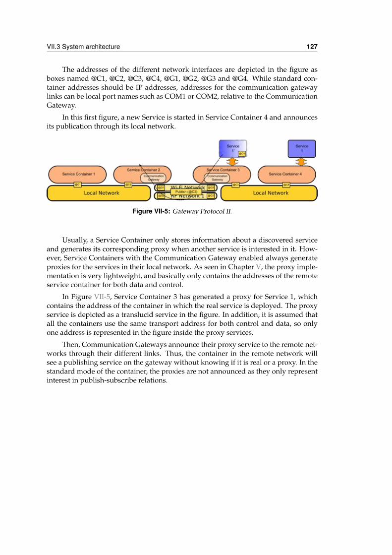
VII.3 System architecture 127
The addresses of the different network interfaces are depicted in the figure asboxes named @C1, @C2, @C3, @C4, @G1, @G2, @G3 and @G4. While standard con-tainer addresses should be IP addresses, addresses for the communication gatewaylinks can be local port names such as COM1 or COM2, relative to the CommunicationGateway.
In this first figure, a new Service is started in Service Container 4 and announcesits publication through its local network.
Figure VII-5: Gateway Protocol II.
Usually, a Service Container only stores information about a discovered serviceand generates its corresponding proxy when another service is interested in it. How-ever, Service Containers with the Communication Gateway enabled always generateproxies for the services in their local network. As seen in Chapter V, the proxy imple-mentation is very lightweight, and basically only contains the addresses of the remoteservice container for both data and control.
In Figure VII-5, Service Container 3 has generated a proxy for Service 1, whichcontains the address of the container in which the real service is deployed. The proxyservice is depicted as a translucid service in the figure. In addition, it is assumed thatall the containers use the same transport address for both control and data, so onlyone address is represented in the figure inside the proxy services.
Then, Communication Gateways announce their proxy service to the remote net-works through their different links. Thus, the container in the remote network willsee a publishing service on the gateway without knowing if it is real or a proxy. In thestandard mode of the container, the proxies are not announced as they only representinterest in publish-subscribe relations.
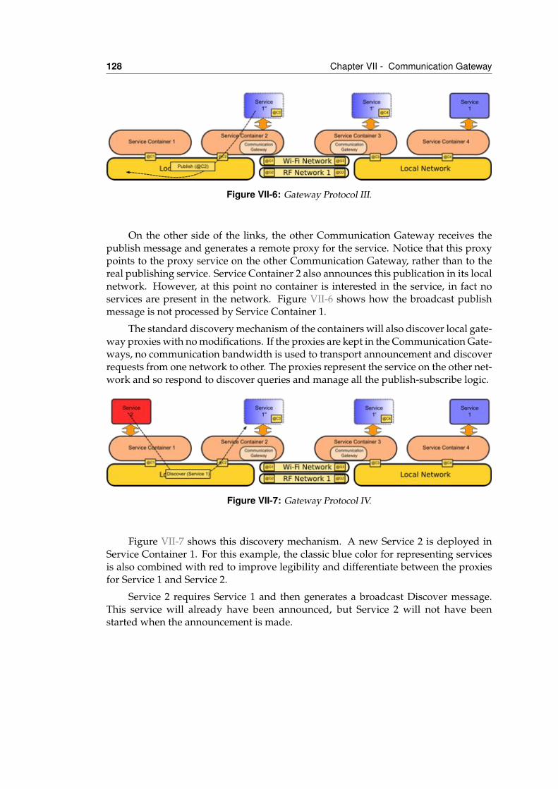
128 Chapter VII - Communication Gateway
Figure VII-6: Gateway Protocol III.
On the other side of the links, the other Communication Gateway receives thepublish message and generates a remote proxy for the service. Notice that this proxypoints to the proxy service on the other Communication Gateway, rather than to thereal publishing service. Service Container 2 also announces this publication in its localnetwork. However, at this point no container is interested in the service, in fact noservices are present in the network. Figure VII-6 shows how the broadcast publishmessage is not processed by Service Container 1.
The standard discovery mechanism of the containers will also discover local gate-way proxies with no modifications. If the proxies are kept in the Communication Gate-ways, no communication bandwidth is used to transport announcement and discoverrequests from one network to other. The proxies represent the service on the other net-work and so respond to discover queries and manage all the publish-subscribe logic.
Figure VII-7: Gateway Protocol IV.
Figure VII-7 shows this discovery mechanism. A new Service 2 is deployed inService Container 1. For this example, the classic blue color for representing servicesis also combined with red to improve legibility and differentiate between the proxiesfor Service 1 and Service 2.
Service 2 requires Service 1 and then generates a broadcast Discover message.This service will already have been announced, but Service 2 will not have beenstarted when the announcement is made.
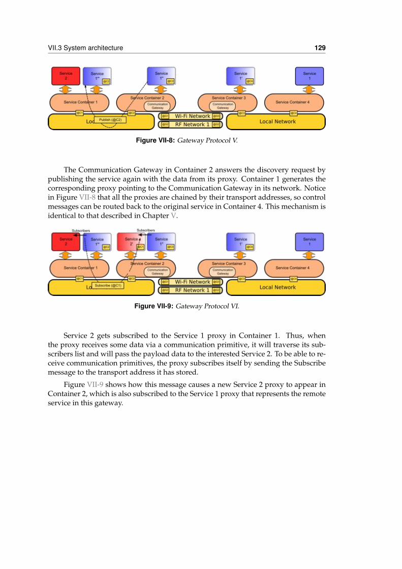
VII.3 System architecture 129
Figure VII-8: Gateway Protocol V.
The Communication Gateway in Container 2 answers the discovery request bypublishing the service again with the data from its proxy. Container 1 generates thecorresponding proxy pointing to the Communication Gateway in its network. Noticein Figure VII-8 that all the proxies are chained by their transport addresses, so controlmessages can be routed back to the original service in Container 4. This mechanism isidentical to that described in Chapter V.
Figure VII-9: Gateway Protocol VI.
Service 2 gets subscribed to the Service 1 proxy in Container 1. Thus, whenthe proxy receives some data via a communication primitive, it will traverse its sub-scribers list and will pass the payload data to the interested Service 2. To be able to re-ceive communication primitives, the proxy subscribes itself by sending the Subscribemessage to the transport address it has stored.
Figure VII-9 shows how this message causes a new Service 2 proxy to appear inContainer 2, which is also subscribed to the Service 1 proxy that represents the remoteservice in this gateway.
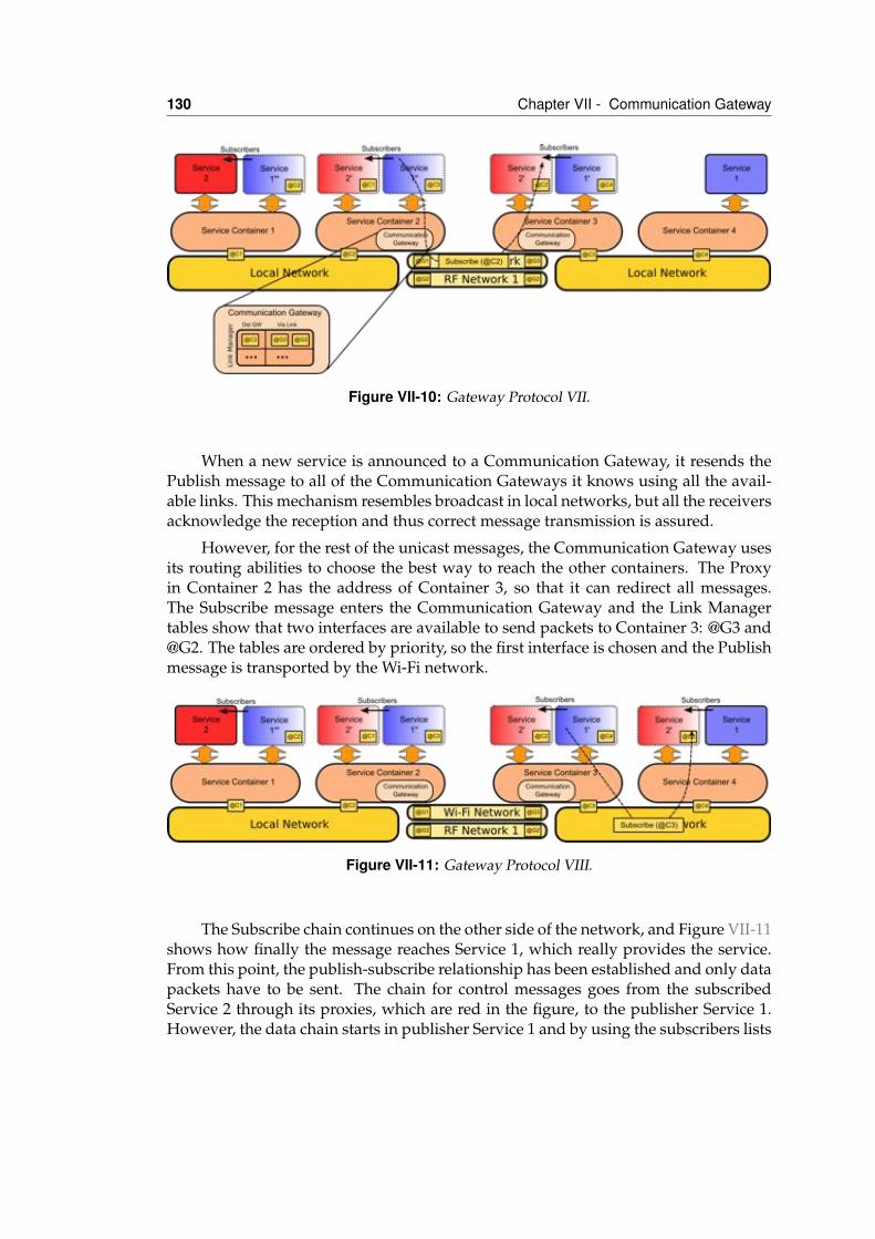
130 Chapter VII - Communication Gateway
Figure VII-10: Gateway Protocol VII.
When a new service is announced to a Communication Gateway, it resends thePublish message to all of the Communication Gateways it knows using all the avail-able links. This mechanism resembles broadcast in local networks, but all the receiversacknowledge the reception and thus correct message transmission is assured.
However, for the rest of the unicast messages, the Communication Gateway usesits routing abilities to choose the best way to reach the other containers. The Proxyin Container 2 has the address of Container 3, so that it can redirect all messages.The Subscribe message enters the Communication Gateway and the Link Managertables show that two interfaces are available to send packets to Container 3: @G3 and@G2. The tables are ordered by priority, so the first interface is chosen and the Publishmessage is transported by the Wi-Fi network.
Figure VII-11: Gateway Protocol VIII.
The Subscribe chain continues on the other side of the network, and Figure VII-11shows how finally the message reaches Service 1, which really provides the service.From this point, the publish-subscribe relationship has been established and only datapackets have to be sent. The chain for control messages goes from the subscribedService 2 through its proxies, which are red in the figure, to the publisher Service 1.However, the data chain starts in publisher Service 1 and by using the subscribers lists
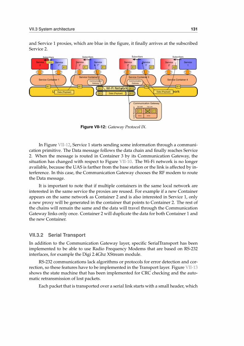
VII.3 System architecture 131
and Service 1 proxies, which are blue in the figure, it finally arrives at the subscribedService 2.
Figure VII-12: Gateway Protocol IX.
In Figure VII-12, Service 1 starts sending some information through a communi-cation primitive. The Data message follows the data chain and finally reaches Service2. When the message is routed in Container 3 by its Communication Gateway, thesituation has changed with respect to Figure VII-10. The Wi-Fi network is no longeravailable, because the UAS is farther from the base station or the link is affected by in-terference. In this case, the Communication Gateway chooses the RF modem to routethe Data message.
It is important to note that if multiple containers in the same local network areinterested in the same service the proxies are reused. For example if a new Containerappears on the same network as Container 2 and is also interested in Service 1, onlya new proxy will be generated in the container that points to Container 2. The rest ofthe chains will remain the same and the data will travel through the CommunicationGateway links only once. Container 2 will duplicate the data for both Container 1 andthe new Container.
VII.3.2 Serial TransportIn addition to the Communication Gateway layer, specific SerialTransport has beenimplemented to be able to use Radio Frequency Modems that are based on RS-232interfaces, for example the Digi 2.4Ghz XStream module.
RS-232 communications lack algorithms or protocols for error detection and cor-rection, so these features have to be implemented in the Transport layer. Figure VII-13shows the state machine that has been implemented for CRC checking and the auto-matic retransmission of lost packets.
Each packet that is transported over a serial link starts with a small header, which
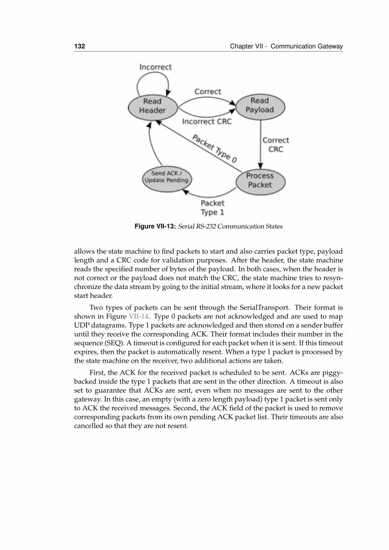
132 Chapter VII - Communication Gateway
Figure VII-13: Serial RS-232 Communication States
allows the state machine to find packets to start and also carries packet type, payloadlength and a CRC code for validation purposes. After the header, the state machinereads the specified number of bytes of the payload. In both cases, when the header isnot correct or the payload does not match the CRC, the state machine tries to resyn-chronize the data stream by going to the initial stream, where it looks for a new packetstart header.
Two types of packets can be sent through the SerialTransport. Their format isshown in Figure VII-14. Type 0 packets are not acknowledged and are used to mapUDP datagrams. Type 1 packets are acknowledged and then stored on a sender bufferuntil they receive the corresponding ACK. Their format includes their number in thesequence (SEQ). A timeout is configured for each packet when it is sent. If this timeoutexpires, then the packet is automatically resent. When a type 1 packet is processed bythe state machine on the receiver, two additional actions are taken.
First, the ACK for the received packet is scheduled to be sent. ACKs are piggy-backed inside the type 1 packets that are sent in the other direction. A timeout is alsoset to guarantee that ACKs are sent, even when no messages are sent to the othergateway. In this case, an empty (with a zero length payload) type 1 packet is sent onlyto ACK the received messages. Second, the ACK field of the packet is used to removecorresponding packets from its own pending ACK packet list. Their timeouts are alsocancelled so that they are not resent.
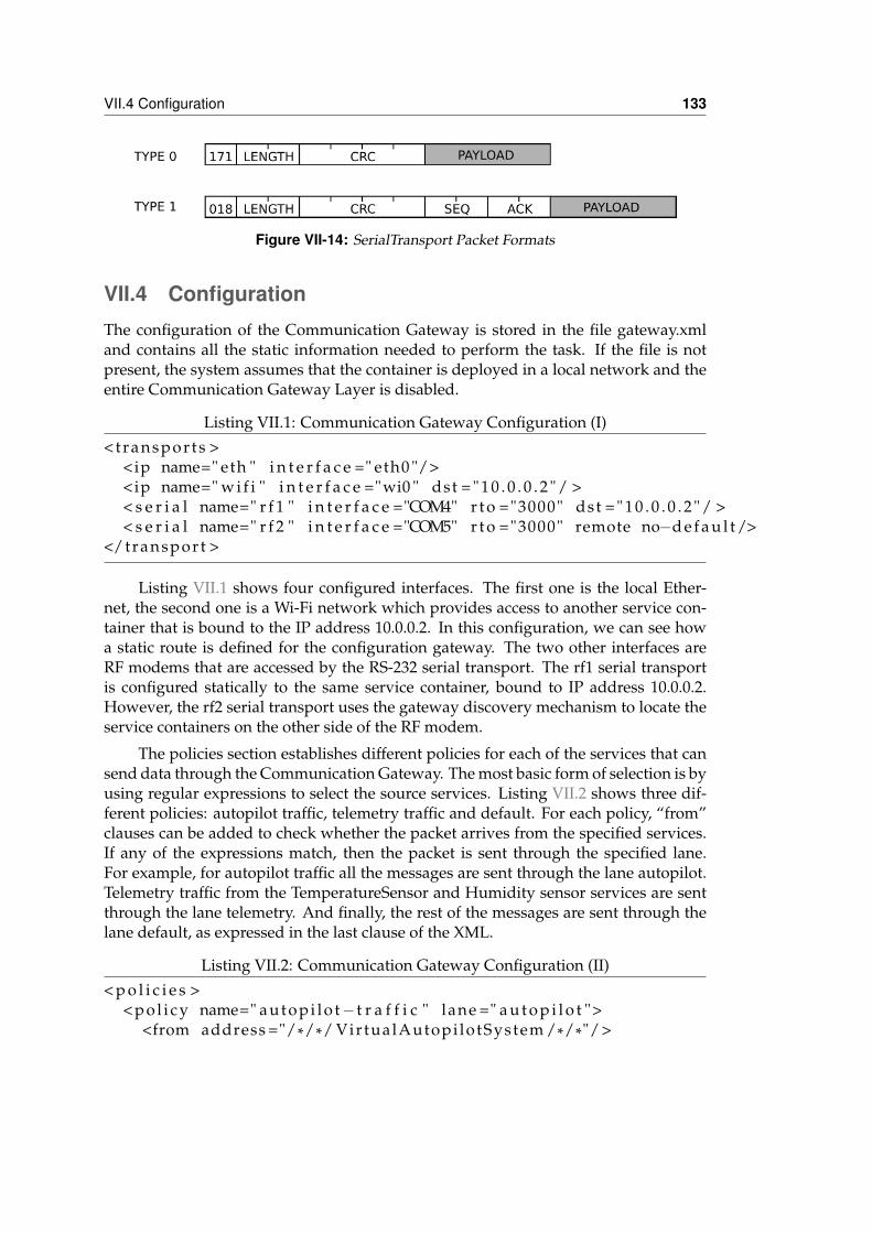
VII.4 Configuration 133
Figure VII-14: SerialTransport Packet Formats
VII.4 ConfigurationThe configuration of the Communication Gateway is stored in the file gateway.xmland contains all the static information needed to perform the task. If the file is notpresent, the system assumes that the container is deployed in a local network and theentire Communication Gateway Layer is disabled.
Listing VII.1: Communication Gateway Configuration (I)<t ranspor ts >
<ip name=" eth " i n t e r f a c e =" eth0 "/><ip name=" w i f i " i n t e r f a c e ="wi0 " dst = " 1 0 . 0 . 0 . 2 " / >< s e r i a l name=" r f 1 " i n t e r f a c e ="COM4" r t o ="3000" dst = " 1 0 . 0 . 0 . 2 " / >< s e r i a l name=" r f 2 " i n t e r f a c e ="COM5" r t o ="3000" remote no−d e f a u l t />
</transport >
Listing VII.1 shows four configured interfaces. The first one is the local Ether-net, the second one is a Wi-Fi network which provides access to another service con-tainer that is bound to the IP address 10.0.0.2. In this configuration, we can see howa static route is defined for the configuration gateway. The two other interfaces areRF modems that are accessed by the RS-232 serial transport. The rf1 serial transportis configured statically to the same service container, bound to IP address 10.0.0.2.However, the rf2 serial transport uses the gateway discovery mechanism to locate theservice containers on the other side of the RF modem.
The policies section establishes different policies for each of the services that cansend data through the Communication Gateway. The most basic form of selection is byusing regular expressions to select the source services. Listing VII.2 shows three dif-ferent policies: autopilot traffic, telemetry traffic and default. For each policy, “from”clauses can be added to check whether the packet arrives from the specified services.If any of the expressions match, then the packet is sent through the specified lane.For example, for autopilot traffic all the messages are sent through the lane autopilot.Telemetry traffic from the TemperatureSensor and Humidity sensor services are sentthrough the lane telemetry. And finally, the rest of the messages are sent through thelane default, as expressed in the last clause of the XML.
Listing VII.2: Communication Gateway Configuration (II)< p o l i c i e s >
<pol i cy name=" au topi lo t− t r a f f i c " lane =" a u t o p i l o t "><from address ="/*/*/ VirtualAutopi lotSystem /*/*"/ >
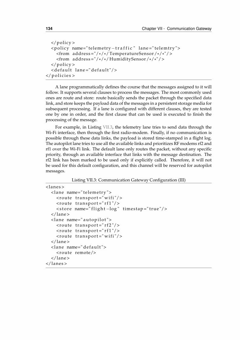
134 Chapter VII - Communication Gateway
</policy ><p ol i cy name=" telemetry− t r a f f i c " lane =" te lemtry ">
<from address ="/*/*/ TemperatureSensor /*/*"/ ><from address ="/*/*/ HumiditySensor /*/*"/ >
</pol icy >< d e f a u l t lane =" d e f a u l t "/>
</ p o l i c i e s >
A lane programmatically defines the course that the messages assigned to it willfollow. It supports several clauses to process the messages. The most commonly usedones are route and store: route basically sends the packet through the specified datalink, and store keeps the payload data of the messages in a persistent storage media forsubsequent processing. If a lane is configured with different clauses, they are testedone by one in order, and the first clause that can be used is executed to finish theprocessing of the message.
For example, in Listing VII.3, the telemetry lane tries to send data through theWi-Fi interface, then through the first radio-modem. Finally, if no communication ispossible through these data links, the payload is stored time-stamped in a flight log.The autopilot lane tries to use all the available links and prioritizes RF modems rf2 andrf1 over the Wi-Fi link. The default lane only routes the packet, without any specificpriority, through an available interface that links with the message destination. Therf2 link has been marked to be used only if explicitly called. Therefore, it will notbe used for this default configuration, and this channel will be reserved for autopilotmessages.
Listing VII.3: Communication Gateway Configuration (III)<lanes >
<lane name=" te lemetry "><route t r a n s p o r t =" w i f i "/><route t r a n s p o r t =" r f 1 "/>< s t o r e name=" f l i g h t −log " t imestap =" t rue "/>
</lane ><lane name=" a u t o p i l o t ">
<route t r a n s p o r t =" r f 2 "/><route t r a n s p o r t =" r f 1 "/><route t r a n s p o r t =" w i f i "/>
</lane ><lane name=" d e f a u l t ">
<route remote/></lane >
</lanes >
VII.5 Conclusions 135
VII.5 ConclusionsMarea protocols are designed to operate over an Ethernet local area network. Morespecifically, they depend on multicast and broadcast messaging being very low-costoperations. This cannot be assured in the communication links that are typically usedfor UAS air-to-ground communications. In addition, UAV environments usually havedifferent links to support communication in different ranges and to provide redun-dancy when a link is down. These point-to-point links usually do not support multi-cast, and may have associated costs that restrict their usage to specific situations or tovery important transmissions. The UAV should be intelligent enough to send the datathrough the most appropriate channel.
The Communication Gateway is Marea’s specific system for managing air-to-airand air-to-ground UAS communications. This system’s main purpose is to make thenetwork transparent to the different services that use it. This task can be divided intotwo functionalities: a basic routing functionality and a proxy to improve efficiency.In this chapter, we describe the architecture and integration of the CommunicationGateway into the rest of the Marea stack. In addition, Serial Transport has been imple-mented to allow the use of non-IP radio modem-based communications. Finally, theXML configuration files that are used to configure the Communication Gateway aredepicted.

VIIIPerformance evaluation
VIII.1 IntroductionMarea was not designed for hard real-time applications, i.e. the control loop of anautopilot. In our architectural view, these real-time requirements are contained insideblack box services, i.e. the autopilot. These specific services are implemented accord-ing to hard real-time constraints, while the connection with the rest of the avionicssystem can be made with less constraints. For example, in our platform we use aUAV Navigation(UAV Navigation, n.d.) commercial autopilot that is implemented asa monolithic application over a real-time operating system (RTOS). This componentis connected by a serial port to a Marea service, the Virtual Autopilot System (VAS),which acts as a driver to the other services in the platform. In the communicationbetween the VAS and the service that feeds the waypoints from the flight plan, softreal-time requirements are sufficient, i.e. there is low variance. However, if Mareahas to be used to implement complex interactions between services, low latencies andhigh bandwidths should be attained.
Hard real-time systems require predictability, but this is very difficult to achievein distributed systems, as most packet-based networks involve unpredictable laten-
137
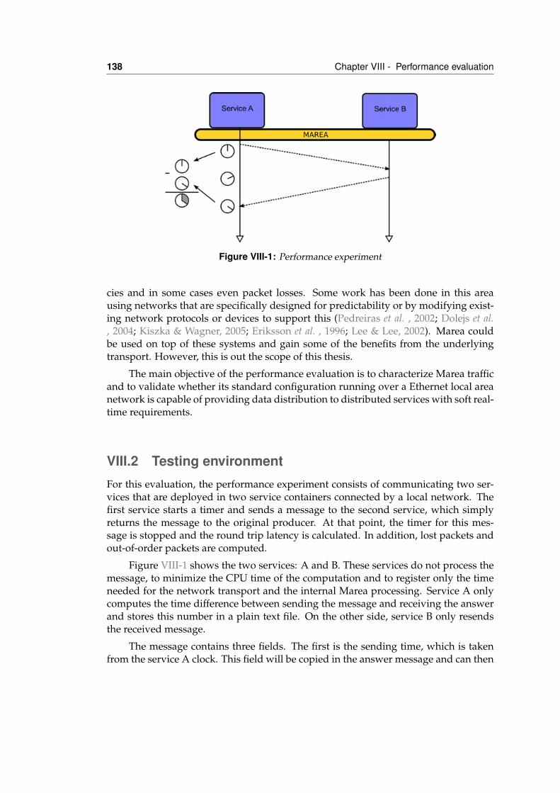
138 Chapter VIII - Performance evaluation
Figure VIII-1: Performance experiment
cies and in some cases even packet losses. Some work has been done in this areausing networks that are specifically designed for predictability or by modifying exist-ing network protocols or devices to support this (Pedreiras et al. , 2002; Dolejs et al., 2004; Kiszka & Wagner, 2005; Eriksson et al. , 1996; Lee & Lee, 2002). Marea couldbe used on top of these systems and gain some of the benefits from the underlyingtransport. However, this is out the scope of this thesis.
The main objective of the performance evaluation is to characterize Marea trafficand to validate whether its standard configuration running over a Ethernet local areanetwork is capable of providing data distribution to distributed services with soft real-time requirements.
VIII.2 Testing environmentFor this evaluation, the performance experiment consists of communicating two ser-vices that are deployed in two service containers connected by a local network. Thefirst service starts a timer and sends a message to the second service, which simplyreturns the message to the original producer. At that point, the timer for this mes-sage is stopped and the round trip latency is calculated. In addition, lost packets andout-of-order packets are computed.
Figure VIII-1 shows the two services: A and B. These services do not process themessage, to minimize the CPU time of the computation and to register only the timeneeded for the network transport and the internal Marea processing. Service A onlycomputes the time difference between sending the message and receiving the answerand stores this number in a plain text file. On the other side, service B only resendsthe received message.
The message contains three fields. The first is the sending time, which is takenfrom the service A clock. This field will be copied in the answer message and can then
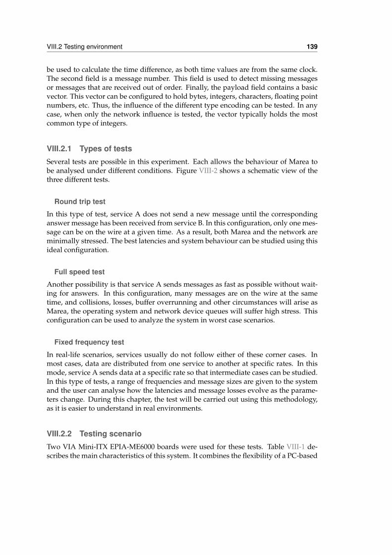
VIII.2 Testing environment 139
be used to calculate the time difference, as both time values are from the same clock.The second field is a message number. This field is used to detect missing messagesor messages that are received out of order. Finally, the payload field contains a basicvector. This vector can be configured to hold bytes, integers, characters, floating pointnumbers, etc. Thus, the influence of the different type encoding can be tested. In anycase, when only the network influence is tested, the vector typically holds the mostcommon type of integers.
VIII.2.1 Types of testsSeveral tests are possible in this experiment. Each allows the behaviour of Marea tobe analysed under different conditions. Figure VIII-2 shows a schematic view of thethree different tests.
Round trip test
In this type of test, service A does not send a new message until the correspondinganswer message has been received from service B. In this configuration, only one mes-sage can be on the wire at a given time. As a result, both Marea and the network areminimally stressed. The best latencies and system behaviour can be studied using thisideal configuration.
Full speed test
Another possibility is that service A sends messages as fast as possible without wait-ing for answers. In this configuration, many messages are on the wire at the sametime, and collisions, losses, buffer overrunning and other circumstances will arise asMarea, the operating system and network device queues will suffer high stress. Thisconfiguration can be used to analyze the system in worst case scenarios.
Fixed frequency test
In real-life scenarios, services usually do not follow either of these corner cases. Inmost cases, data are distributed from one service to another at specific rates. In thismode, service A sends data at a specific rate so that intermediate cases can be studied.In this type of tests, a range of frequencies and message sizes are given to the systemand the user can analyse how the latencies and message losses evolve as the parame-ters change. During this chapter, the test will be carried out using this methodology,as it is easier to understand in real environments.
VIII.2.2 Testing scenarioTwo VIA Mini-ITX EPIA-ME6000 boards were used for these tests. Table VIII-1 de-scribes the main characteristics of this system. It combines the flexibility of a PC-based
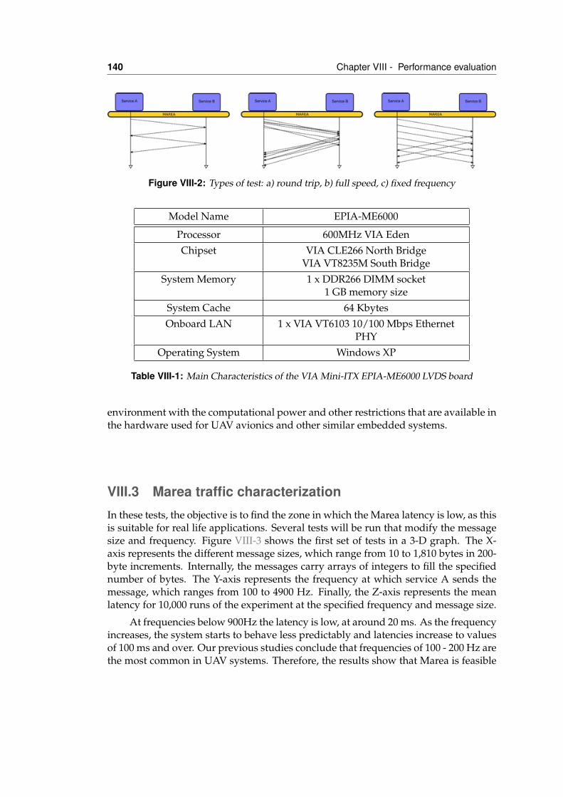
140 Chapter VIII - Performance evaluation
Figure VIII-2: Types of test: a) round trip, b) full speed, c) fixed frequency
Model Name EPIA-ME6000
Processor 600MHz VIA EdenChipset VIA CLE266 North Bridge
VIA VT8235M South BridgeSystem Memory 1 x DDR266 DIMM socket
1 GB memory sizeSystem Cache 64 KbytesOnboard LAN 1 x VIA VT6103 10/100 Mbps Ethernet
PHYOperating System Windows XP
Table VIII-1: Main Characteristics of the VIA Mini-ITX EPIA-ME6000 LVDS board
environment with the computational power and other restrictions that are available inthe hardware used for UAV avionics and other similar embedded systems.
VIII.3 Marea traffic characterizationIn these tests, the objective is to find the zone in which the Marea latency is low, as thisis suitable for real life applications. Several tests will be run that modify the messagesize and frequency. Figure VIII-3 shows the first set of tests in a 3-D graph. The X-axis represents the different message sizes, which range from 10 to 1,810 bytes in 200-byte increments. Internally, the messages carry arrays of integers to fill the specifiednumber of bytes. The Y-axis represents the frequency at which service A sends themessage, which ranges from 100 to 4900 Hz. Finally, the Z-axis represents the meanlatency for 10,000 runs of the experiment at the specified frequency and message size.
At frequencies below 900Hz the latency is low, at around 20 ms. As the frequencyincreases, the system starts to behave less predictably and latencies increase to valuesof 100 ms and over. Our previous studies conclude that frequencies of 100 - 200 Hz arethe most common in UAV systems. Therefore, the results show that Marea is feasible
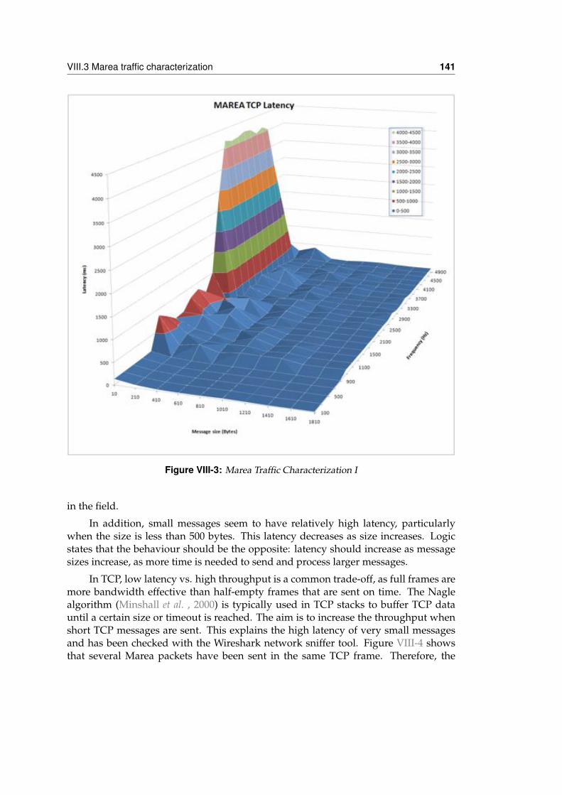
VIII.3 Marea traffic characterization 141
Figure VIII-3: Marea Traffic Characterization I
in the field.
In addition, small messages seem to have relatively high latency, particularlywhen the size is less than 500 bytes. This latency decreases as size increases. Logicstates that the behaviour should be the opposite: latency should increase as messagesizes increase, as more time is needed to send and process larger messages.
In TCP, low latency vs. high throughput is a common trade-off, as full frames aremore bandwidth effective than half-empty frames that are sent on time. The Naglealgorithm (Minshall et al. , 2000) is typically used in TCP stacks to buffer TCP datauntil a certain size or timeout is reached. The aim is to increase the throughput whenshort TCP messages are sent. This explains the high latency of very small messagesand has been checked with the Wireshark network sniffer tool. Figure VIII-4 showsthat several Marea packets have been sent in the same TCP frame. Therefore, the
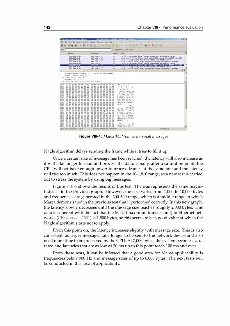
142 Chapter VIII - Performance evaluation
Figure VIII-4: Marea TCP frames for small messages
Nagle algorithm delays sending the frame while it tries to fill it up.
Once a certain size of message has been reached, the latency will also increase asit will take longer to send and process the data. Finally, after a saturation point, theCPU will not have enough power to process frames at the same rate and the latencywill rise too much. This does not happen in the 10-1,810 range, so a new test is carriedout to stress the system by using big messages.
Figure VIII-5 shows the results of this test. The axis represents the same magni-tudes as in the previous graph. However, the size varies from 1,000 to 10,000 bytesand frequencies are generated in the 300-500 range, which is a middle range in whichMarea demonstrated in the previous test that it performed correctly. In this new graph,the latency slowly decreases until the message size reaches roughly 2,000 bytes. Thisdata is coherent with the fact that the MTU (maximum transfer unit) in Ethernet net-works (Chase et al. , 2001) is 1,500 bytes, so this seems to be a good value at which theNagle algorithm starts not to apply.
From this point on, the latency increases slightly with message size. This is alsoconsistent, as larger messages take longer to be sent to the network device and alsoneed more time to be processed by the CPU. At 7,000 bytes, the system becomes satu-rated and latencies that are as low as 20 ms up to this point reach 100 ms and over.
From these tests, it can be inferred that a good area for Marea applicability isfrequencies below 900 Hz and message sizes of up to 6,000 bytes. The next tests willbe conducted in this area of applicability.
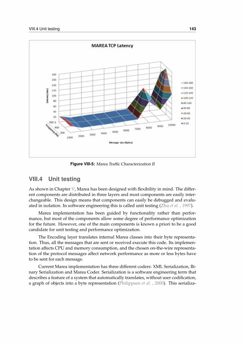
VIII.4 Unit testing 143
Figure VIII-5: Marea Traffic Characterization II
VIII.4 Unit testingAs shown in Chapter V, Marea has been designed with flexibility in mind. The differ-ent components are distributed in three layers and most components are easily inter-changeable. This design means that components can easily be debugged and evalu-ated in isolation. In software engineering this is called unit testing (Zhu et al. , 1997).
Marea implementation has been guided by functionality rather than perfor-mance, but most of the components allow some degree of performance optimizationfor the future. However, one of the main components is known a priori to be a goodcandidate for unit testing and performance optimization.
The Encoding layer translates internal Marea classes into their byte representa-tion. Thus, all the messages that are sent or received execute this code. Its implemen-tation affects CPU and memory consumption, and the chosen on-the-wire representa-tion of the protocol messages affect network performance as more or less bytes haveto be sent for each message.
Current Marea implementation has three different coders: XML Serialization, Bi-nary Serialization and Marea Coder. Serialization is a software engineering term thatdescribes a feature of a system that automatically translates, without user codification,a graph of objects into a byte representation (Philippsen et al. , 2000). This serializa-
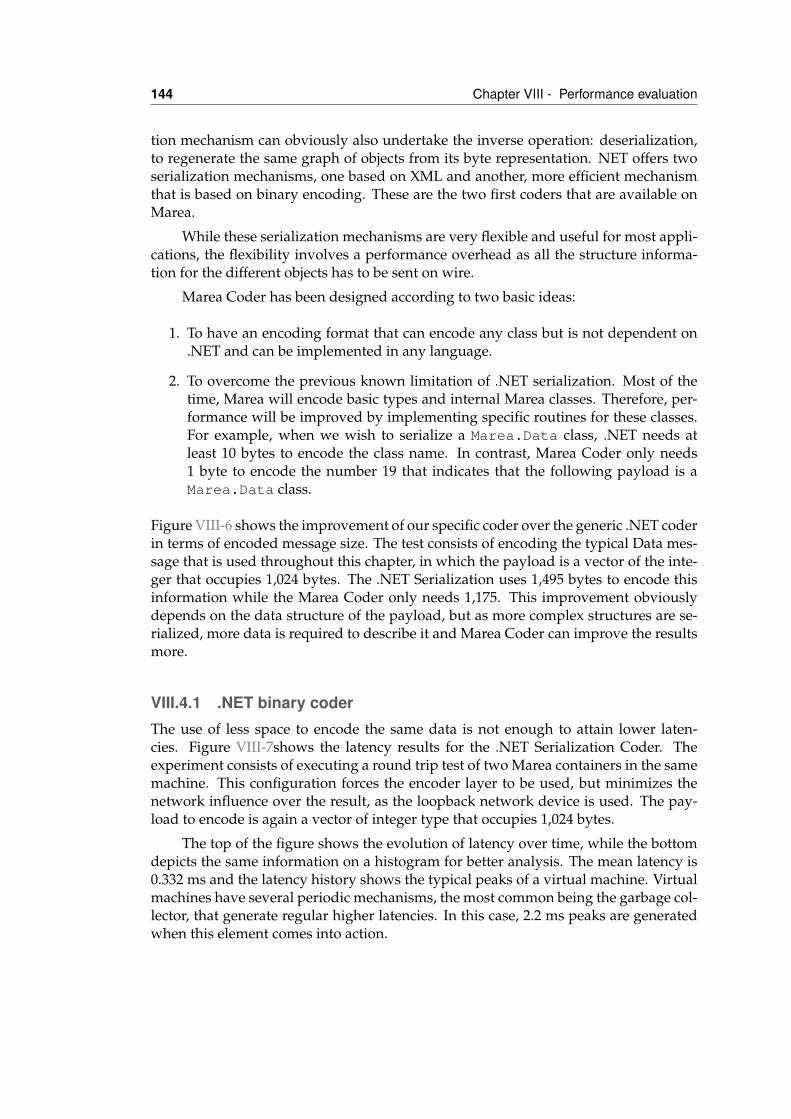
144 Chapter VIII - Performance evaluation
tion mechanism can obviously also undertake the inverse operation: deserialization,to regenerate the same graph of objects from its byte representation. NET offers twoserialization mechanisms, one based on XML and another, more efficient mechanismthat is based on binary encoding. These are the two first coders that are available onMarea.
While these serialization mechanisms are very flexible and useful for most appli-cations, the flexibility involves a performance overhead as all the structure informa-tion for the different objects has to be sent on wire.
Marea Coder has been designed according to two basic ideas:
1. To have an encoding format that can encode any class but is not dependent on.NET and can be implemented in any language.
2. To overcome the previous known limitation of .NET serialization. Most of thetime, Marea will encode basic types and internal Marea classes. Therefore, per-formance will be improved by implementing specific routines for these classes.For example, when we wish to serialize a Marea.Data class, .NET needs atleast 10 bytes to encode the class name. In contrast, Marea Coder only needs1 byte to encode the number 19 that indicates that the following payload is aMarea.Data class.
Figure VIII-6 shows the improvement of our specific coder over the generic .NET coderin terms of encoded message size. The test consists of encoding the typical Data mes-sage that is used throughout this chapter, in which the payload is a vector of the inte-ger that occupies 1,024 bytes. The .NET Serialization uses 1,495 bytes to encode thisinformation while the Marea Coder only needs 1,175. This improvement obviouslydepends on the data structure of the payload, but as more complex structures are se-rialized, more data is required to describe it and Marea Coder can improve the resultsmore.
VIII.4.1 .NET binary coderThe use of less space to encode the same data is not enough to attain lower laten-cies. Figure VIII-7shows the latency results for the .NET Serialization Coder. Theexperiment consists of executing a round trip test of two Marea containers in the samemachine. This configuration forces the encoder layer to be used, but minimizes thenetwork influence over the result, as the loopback network device is used. The pay-load to encode is again a vector of integer type that occupies 1,024 bytes.
The top of the figure shows the evolution of latency over time, while the bottomdepicts the same information on a histogram for better analysis. The mean latency is0.332 ms and the latency history shows the typical peaks of a virtual machine. Virtualmachines have several periodic mechanisms, the most common being the garbage col-lector, that generate regular higher latencies. In this case, 2.2 ms peaks are generatedwhen this element comes into action.
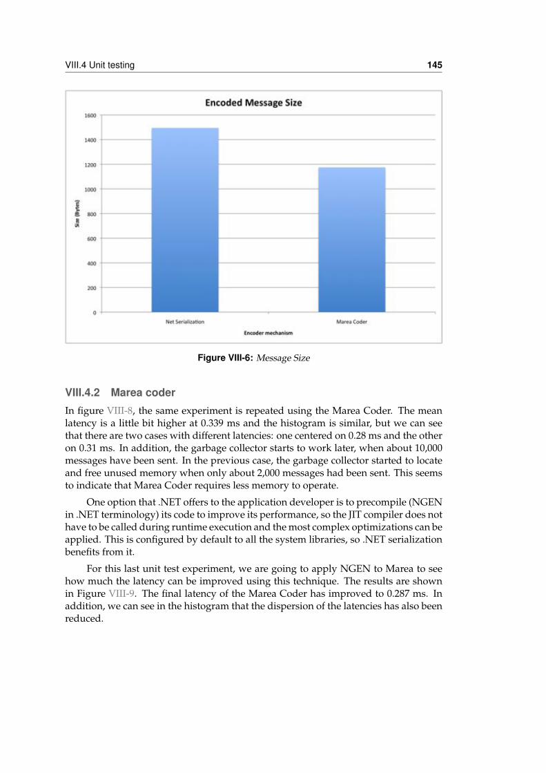
VIII.4 Unit testing 145
Figure VIII-6: Message Size
VIII.4.2 Marea coderIn figure VIII-8, the same experiment is repeated using the Marea Coder. The meanlatency is a little bit higher at 0.339 ms and the histogram is similar, but we can seethat there are two cases with different latencies: one centered on 0.28 ms and the otheron 0.31 ms. In addition, the garbage collector starts to work later, when about 10,000messages have been sent. In the previous case, the garbage collector started to locateand free unused memory when only about 2,000 messages had been sent. This seemsto indicate that Marea Coder requires less memory to operate.
One option that .NET offers to the application developer is to precompile (NGENin .NET terminology) its code to improve its performance, so the JIT compiler does nothave to be called during runtime execution and the most complex optimizations can beapplied. This is configured by default to all the system libraries, so .NET serializationbenefits from it.
For this last unit test experiment, we are going to apply NGEN to Marea to seehow much the latency can be improved using this technique. The results are shownin Figure VIII-9. The final latency of the Marea Coder has improved to 0.287 ms. Inaddition, we can see in the histogram that the dispersion of the latencies has also beenreduced.
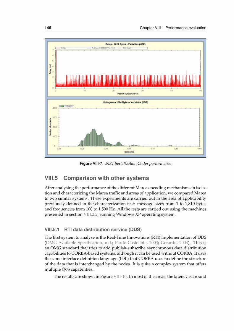
146 Chapter VIII - Performance evaluation
Figure VIII-7: .NET Serialization Coder performance
VIII.5 Comparison with other systemsAfter analysing the performance of the different Marea encoding mechanisms in isola-tion and characterizing the Marea traffic and areas of application, we compared Mareato two similar systems. These experiments are carried out in the area of applicabilitypreviously defined in the characterization test: message sizes from 1 to 1,810 bytesand frequencies from 100 to 1,500 Hz. All the tests are carried out using the machinespresented in section VIII.2.2, running Windows XP operating system.
VIII.5.1 RTI data distribution service (DDS)The first system to analyse is the Real-Time Innovations (RTI) implementation of DDS(OMG Available Specification, n.d.; Pardo-Castellote, 2003; Gerardo, 2004). This isan OMG standard that tries to add publish-subscribe asynchronous data distributioncapabilities to CORBA-based systems, although it can be used without CORBA. It usesthe same interface definition language (IDL) that CORBA uses to define the structureof the data that is interchanged by the nodes. It is quite a complex system that offersmultiple QoS capabilities.
The results are shown in Figure VIII-10. In most of the areas, the latency is around
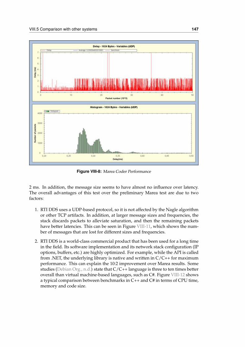
VIII.5 Comparison with other systems 147
Figure VIII-8: Marea Coder Performance
2 ms. In addition, the message size seems to have almost no influence over latency.The overall advantages of this test over the preliminary Marea test are due to twofactors:
1. RTI DDS uses a UDP-based protocol, so it is not affected by the Nagle algorithmor other TCP artifacts. In addition, at larger message sizes and frequencies, thestack discards packets to alleviate saturation, and then the remaining packetshave better latencies. This can be seen in Figure VIII-11, which shows the num-ber of messages that are lost for different sizes and frequencies.
2. RTI DDS is a world-class commercial product that has been used for a long timein the field. Its software implementation and its network stack configuration (IPoptions, buffers, etc.) are highly optimized. For example, while the API is calledfrom .NET, the underlying library is native and written in C/C++ for maximumperformance. This can explain the 10:2 improvement over Marea results. Somestudies (Debian Org., n.d.) state that C/C++ language is three to ten times betteroverall than virtual machine-based languages, such as C#. Figure VIII-12 showsa typical comparison between benchmarks in C++ and C# in terms of CPU time,memory and code size.
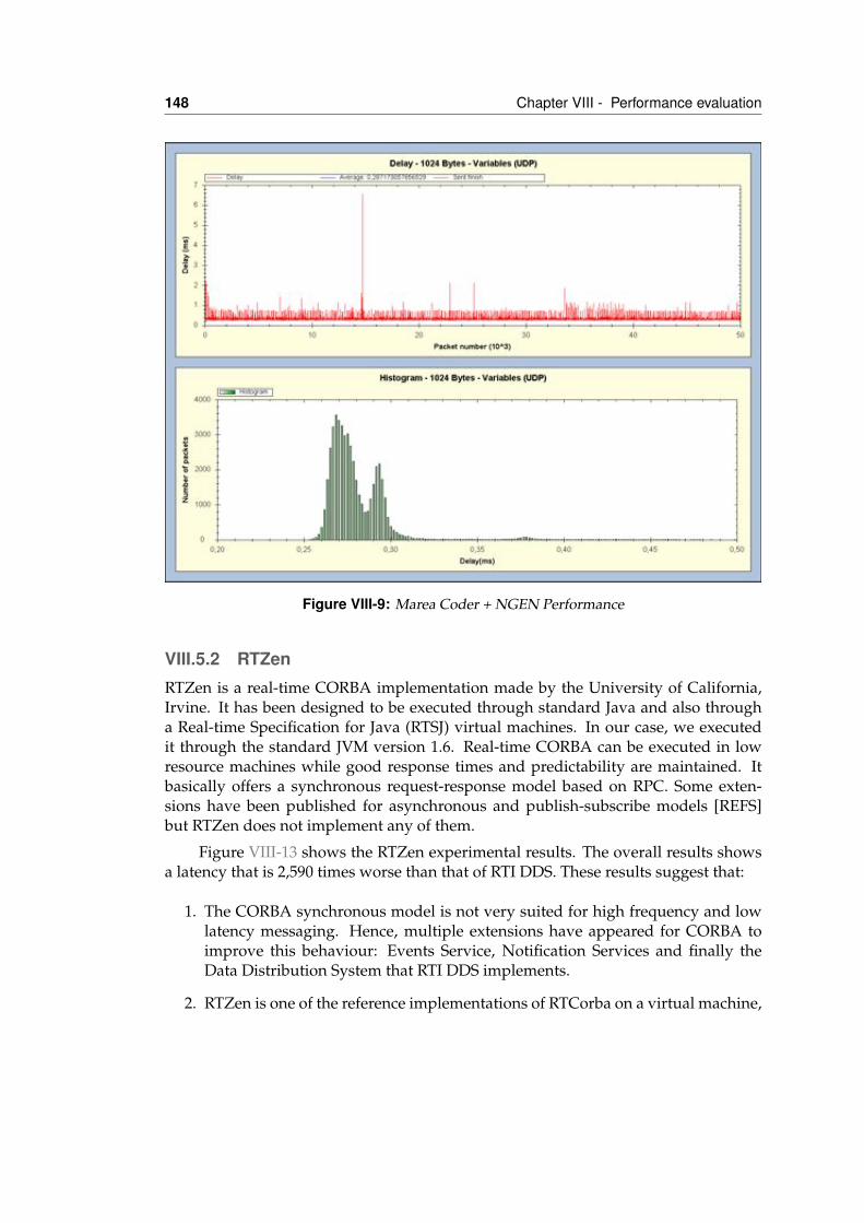
148 Chapter VIII - Performance evaluation
Figure VIII-9: Marea Coder + NGEN Performance
VIII.5.2 RTZenRTZen is a real-time CORBA implementation made by the University of California,Irvine. It has been designed to be executed through standard Java and also througha Real-time Specification for Java (RTSJ) virtual machines. In our case, we executedit through the standard JVM version 1.6. Real-time CORBA can be executed in lowresource machines while good response times and predictability are maintained. Itbasically offers a synchronous request-response model based on RPC. Some exten-sions have been published for asynchronous and publish-subscribe models [REFS]but RTZen does not implement any of them.
Figure VIII-13 shows the RTZen experimental results. The overall results showsa latency that is 2,590 times worse than that of RTI DDS. These results suggest that:
1. The CORBA synchronous model is not very suited for high frequency and lowlatency messaging. Hence, multiple extensions have appeared for CORBA toimprove this behaviour: Events Service, Notification Services and finally theData Distribution System that RTI DDS implements.
2. RTZen is one of the reference implementations of RTCorba on a virtual machine,
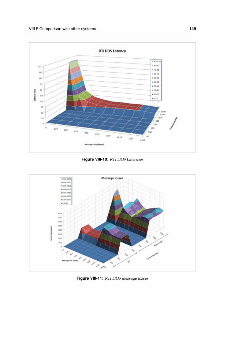
VIII.5 Comparison with other systems 149
Figure VIII-10: RTI DDS Latencies
Figure VIII-11: RTI DDS message losses
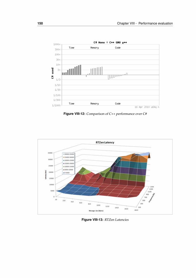
150 Chapter VIII - Performance evaluation
Figure VIII-12: Comparison of C++ performance over C#
Figure VIII-13: RTZen Latencies
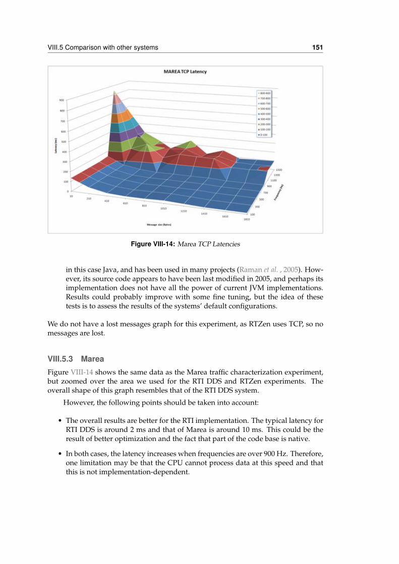
VIII.5 Comparison with other systems 151
Figure VIII-14: Marea TCP Latencies
in this case Java, and has been used in many projects (Raman et al. , 2005). How-ever, its source code appears to have been last modified in 2005, and perhaps itsimplementation does not have all the power of current JVM implementations.Results could probably improve with some fine tuning, but the idea of thesetests is to assess the results of the systems’ default configurations.
We do not have a lost messages graph for this experiment, as RTZen uses TCP, so nomessages are lost.
VIII.5.3 MareaFigure VIII-14 shows the same data as the Marea traffic characterization experiment,but zoomed over the area we used for the RTI DDS and RTZen experiments. Theoverall shape of this graph resembles that of the RTI DDS system.
However, the following points should be taken into account:
• The overall results are better for the RTI implementation. The typical latency forRTI DDS is around 2 ms and that of Marea is around 10 ms. This could be theresult of better optimization and the fact that part of the code base is native.
• In both cases, the latency increases when frequencies are over 900 Hz. Therefore,one limitation may be that the CPU cannot process data at this speed and thatthis is not implementation-dependent.
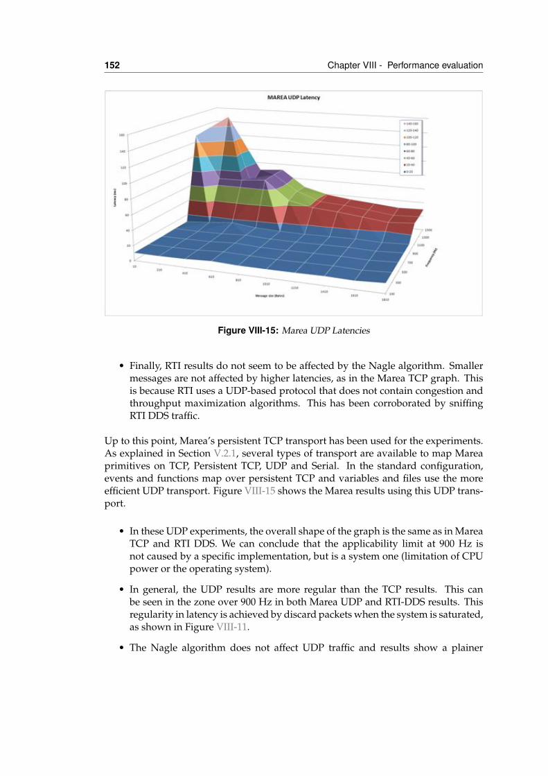
152 Chapter VIII - Performance evaluation
Figure VIII-15: Marea UDP Latencies
• Finally, RTI results do not seem to be affected by the Nagle algorithm. Smallermessages are not affected by higher latencies, as in the Marea TCP graph. Thisis because RTI uses a UDP-based protocol that does not contain congestion andthroughput maximization algorithms. This has been corroborated by sniffingRTI DDS traffic.
Up to this point, Marea’s persistent TCP transport has been used for the experiments.As explained in Section V.2.1, several types of transport are available to map Mareaprimitives on TCP, Persistent TCP, UDP and Serial. In the standard configuration,events and functions map over persistent TCP and variables and files use the moreefficient UDP transport. Figure VIII-15 shows the Marea results using this UDP trans-port.
• In these UDP experiments, the overall shape of the graph is the same as in MareaTCP and RTI DDS. We can conclude that the applicability limit at 900 Hz isnot caused by a specific implementation, but is a system one (limitation of CPUpower or the operating system).
• In general, the UDP results are more regular than the TCP results. This canbe seen in the zone over 900 Hz in both Marea UDP and RTI-DDS results. Thisregularity in latency is achieved by discard packets when the system is saturated,as shown in Figure VIII-11.
• The Nagle algorithm does not affect UDP traffic and results show a plainer
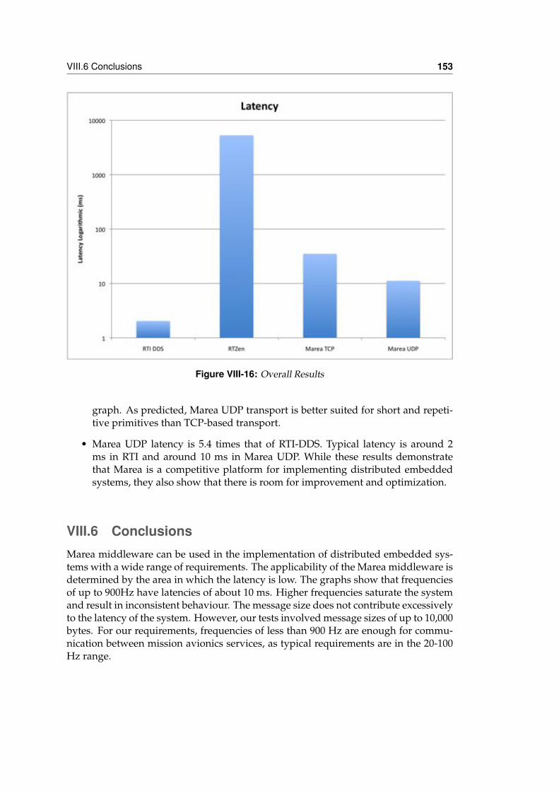
VIII.6 Conclusions 153
Figure VIII-16: Overall Results
graph. As predicted, Marea UDP transport is better suited for short and repeti-tive primitives than TCP-based transport.
• Marea UDP latency is 5.4 times that of RTI-DDS. Typical latency is around 2ms in RTI and around 10 ms in Marea UDP. While these results demonstratethat Marea is a competitive platform for implementing distributed embeddedsystems, they also show that there is room for improvement and optimization.
VIII.6 ConclusionsMarea middleware can be used in the implementation of distributed embedded sys-tems with a wide range of requirements. The applicability of the Marea middleware isdetermined by the area in which the latency is low. The graphs show that frequenciesof up to 900Hz have latencies of about 10 ms. Higher frequencies saturate the systemand result in inconsistent behaviour. The message size does not contribute excessivelyto the latency of the system. However, our tests involved message sizes of up to 10,000bytes. For our requirements, frequencies of less than 900 Hz are enough for commu-nication between mission avionics services, as typical requirements are in the 20-100Hz range.
154 Chapter VIII - Performance evaluation
As Marea is not a performance-guided implementation, there is room for im-provement. Unit testing over an a priori optimization candidate component, the en-coding layer, led to a 13.55% improvement in the usage of a handcrafted implementa-tion.
The Marea implementation that is based on multiple transport for different qual-ity of service needs has proved useful. UDP transport is at least 68% faster than TCPtransport. This is particularly important for small messages. However, TCP offers safedelivery, while UDP drops messages in saturation conditions. This is consistent withthe mapping to UDP datagrams and TCP streams.
Classical synchronous request-response models, such as CORBA, are not wellsuited for some communication patterns, for example short and repetitive data that isdistributed to several listeners. This data is better treated by publish-subscribe basedsystems such as Marea or DDS. Even well-reputed implementations like RTZen areinferior in latency terms.
Marea is a competitive solution for implementing soft real-time distributed em-bedded systems. Our results show that its latency is 473% lower than RTZen, thewell-known University of California Irvine implementation of RTCorba, and only 81%worse than RTI DDS, a commercial, state-of-the-art OMG DDS implementation. Thechart in Figure VIII-16 summarizes these overall results.
IXApplication examples
IX.1 IntroductionDifferent scenarios and applications have been tested during the development ofMarea. As reusability and ease of implementation are Marea’s main characteristics,the objective of these applications is to check the applicability of the Marea service-oriented architecture in multiple environments. In this chapter, we discuss the twomost complex applications that have been developed using Marea.
The first application is the Icarus Simulation Integrated Scenario (ISIS). ISIS pro-vides a simulation environment in which the USAL services that have already beendesigned can interact with others that are in the process of being designed. This allowsthe simulation of complex UAS missions with multiple air or ground-based vehicles.An effort has been made to allow the same services to be reused in both simulated andreal environments, to minimize development costs.
The second application is the Red Eye monitoring system. The objective of thissystem is to help monitor forest fires. The onboard system is installed in a mannedhelicopter with two attached screens. The first is a tactile console for the operator whodesignates which area to scan for hotspots. The second is a small guidance indica-
155
156 Chapter IX - Application examples
tor for the helicopter pilot. This guides the pilot during the scan of the designatedarea. To enable this navigation, the system is equipped with a GPS and an inertialmeasurement unit (IMU). In addition, several cameras are connected to the embed-ded computer and automatically take photos when the helicopter is over a scan point.This imagery is processed to detect hotspots and is sent to the mission operator forcross-checking.
IX.2 Icarus Simulation Integrated ScenarioUAS are becoming one of the main resources used in remote sensing applications incivil and scientific environments. However, the current limitations of non-segregatedairspace makes it extremely difficult to obtain enough flight time to extensively test allthe subsystems that are required to achieve a specific mission.
The use of real flights to test the complete UAS mission infrastructure is ex-pensive and risky. Current legislation requires an area of controlled and segregatedairspace to perform test flights. The UAS system, its associated maintenance systemsand the ground station need to be moved to the assigned airspace. Except for thesmallest UAS, lots of personnel who are involved in the UAS mission also need tobe mobilized. In addition, government permissions and suitable insurance coveragehave to be obtained for the operation. Finally, the possibility of damaging or com-pletely losing the UAS should be considered, particularly when new components orsubsystems are tested. Obviously, all of these restrictions and their associated logisticcosts in time and money make real UAS flight a bad option for experimentation.
Consequently, simulation is essential prior to real flight campaigns. Extensive re-search and experimentation is available in the area of aircraft and autopilot simulation,software-in-the-loop, and even hardware-in-the-loop. However, little or no research isavailable in the area of “mission” or multi-vehicle simulation. It is becoming essentialto model such scenarios, as the operation of UAS will be related to different types ofaerial vehicles and even ground vehicles.
The objective of this section is to introduce a simulation platform that can copewith a variety of civil UAS missions with little reconfiguration time or overheads.This platform must be able to simulate the behaviour of the UAS from the perspectiveof the mission, and to include additional vehicles, each one modelled with differentlevels of granularity. In addition, the simulation must include vehicles, their mutualinteractions, and their interactions with their surrounding environment.
To accomplish this objective, we have implemented a distributed simulationarchitecture in which vehicles and environment are simulated through specializedpieces of software. Marea’s underlying service-oriented communication middlewareprovides the infrastructure to easily implement inter-vehicle coordination and evencoordination with third party applications, to provide additional simulated vehiclesor a simulated environment. We have called this platform the Icarus Simulation Inte-grated Scenario (ISIS). The general goals of the ISIS are as follows:
IX.2 Icarus Simulation Integrated Scenario 157
1. To offer a simulated platform to develop UAS operations that eliminates most ofthe logistic problems that are involved.
2. To design a platform that can interact with other virtual vehicles. Thus, complexcollaborative UAS missions, such as forest fire monitoring or search and rescue,can be developed and tested.
3. To define a standardized set of application interfaces that can be used to ef-ficiently coordinate distributed applications. This is particularly useful whenthird-party applications are incorporated, as it reduces the development time,costs and risks.
IX.2.1 UAS Service Abstraction Layer (USAL)The provision of a common infrastructure to communicate isolated UAS services is notenough to keep the development and maintenance costs of UAV systems low. The ex-istence of an open-architecture avionics package that is specifically designed for UASmay alleviate the development costs by reducing them to a simple parameterization.From the study and definition of several UAS missions, one can identify the mostcommon requirements and functionalities.
The UAS Service Abstraction Layer (USAL) is a set of available services that runon top of the Marea architecture to support most types of UAS missions. USAL can becompared to an operating system. Computers have hardware devices for input/out-put operations. Every device has its own features and the OS provides an abstractionlayer to access such devices in a uniform way. Basically, it offers an Application Pro-gram Interface (API) which provides end-users with efficient and secure access to allhardware elements.
The USAL considers sensors and all payload in general as a computer’s hard-ware devices. The USAL software abstraction layer provides end-user programs toaccess the UAS payload. The USAL also provides many other useful features that aredesigned to simplify the complexity of developing the UAV’s application.
The final goal of the USAL is twofold:
1. First, reduce the “time to market” when a new UAS system is created. The USALand the Marea middleware will simplify the integration of all basic subsystems(autopilot, communications, sensors, etc.) as it already provides all the requiredglue logic.
2. Second, simplify the development of all the systems that are required to accom-plish the actual mission assigned to the UAS. In most cases, this complexity isreduced to specifying the desired flight plan and sensor operation and parame-terizing the specific services that are available in the USAL.
The use of the USAL enables the UAS integrator to abstract from complex andtime-consuming underlying implementation details. The USAL and Marea offer a
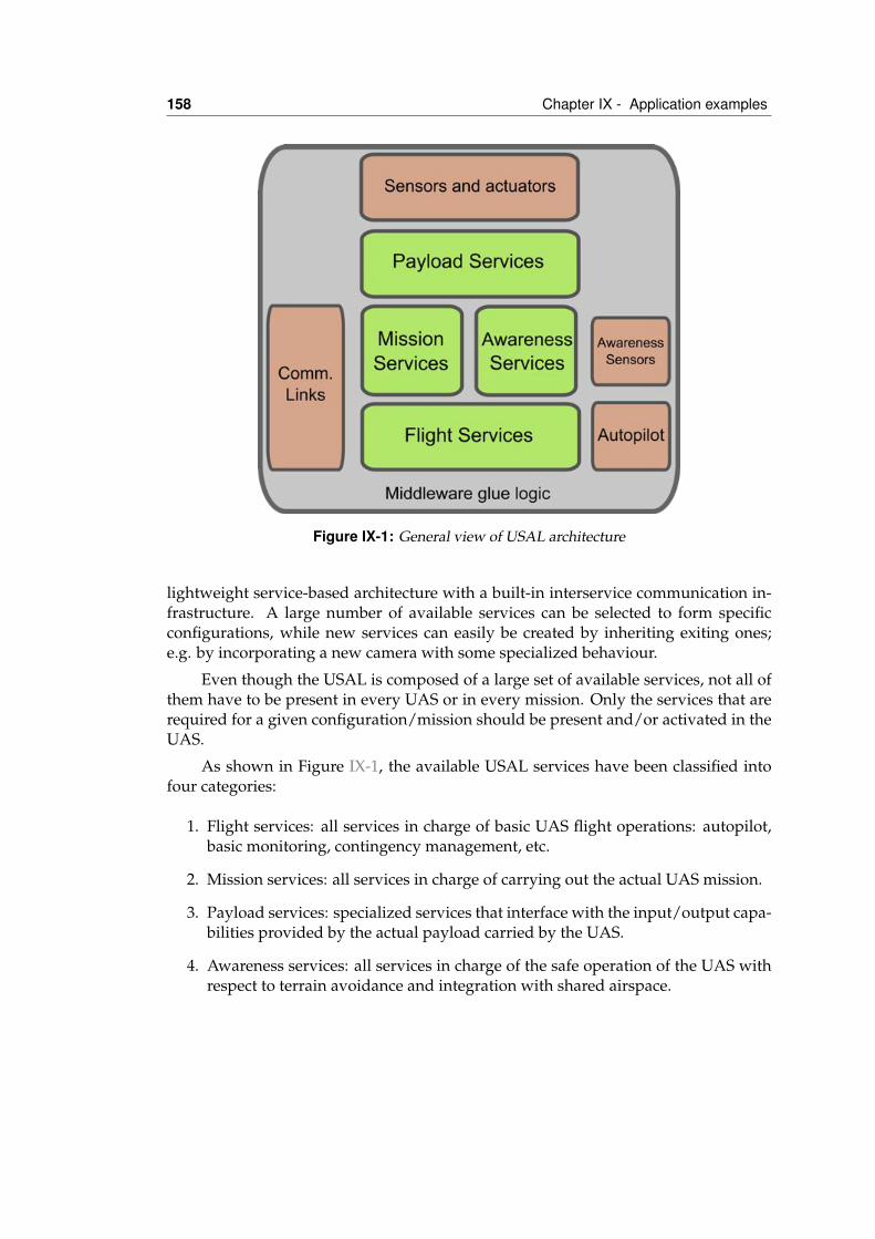
158 Chapter IX - Application examples
Figure IX-1: General view of USAL architecture
lightweight service-based architecture with a built-in interservice communication in-frastructure. A large number of available services can be selected to form specificconfigurations, while new services can easily be created by inheriting exiting ones;e.g. by incorporating a new camera with some specialized behaviour.
Even though the USAL is composed of a large set of available services, not all ofthem have to be present in every UAS or in every mission. Only the services that arerequired for a given configuration/mission should be present and/or activated in theUAS.
As shown in Figure IX-1, the available USAL services have been classified intofour categories:
1. Flight services: all services in charge of basic UAS flight operations: autopilot,basic monitoring, contingency management, etc.
2. Mission services: all services in charge of carrying out the actual UAS mission.
3. Payload services: specialized services that interface with the input/output capa-bilities provided by the actual payload carried by the UAS.
4. Awareness services: all services in charge of the safe operation of the UAS withrespect to terrain avoidance and integration with shared airspace.
IX.2 Icarus Simulation Integrated Scenario 159
IX.2.2 Icarus Simulation Integrated Scenario (ISIS)The main contribution of the USAL is to provide an abstraction layer that allows themission developer to reuse these components and that gives guiding directives onhow the services should interchange avionics information with each other. The avail-able services cover an important part of the generic functionalities that are presentin many missions. Therefore, to adapt our aircraft to a new mission, it is enough toreconfigure the services that are deployed in the UAS boards.
However, this infrastructure has been designed to be onboard the airframe, tocontrol the flight and operation of the UAS. Now, we want to reuse these existingcomponents to build up a simulator. By using the USAL and the Marea middleware,we guarantee that the components that are developed in the simulator will run withno modifications to the UAS on the aircraft. In addition, several components of theUSAL can also be applied in the simulator to minimize the development cost.
The key idea here is to have a component that “behaves” like an aircraft. In thereal UAS, this software component is the Virtual Autopilot System (VAS) that imple-ments the interface with the specific autopilot in the USAL. The VAS accepts com-mands and waypoints to instruct the autopilot to follow the designated flight plan.It also generates a telemetry stream that contains the attitude, position and status ofthe airframe. If we develop a service that respects the VAS interface, the rest of theservices in the system will not notice whether the VAS is commanding a real aircraftor a simulated aircraft.
Figure IX-2 a) shows the default configuration for a real UAS. The autopilot re-ceives commands and produces telemetry via the VAS interface. The information istransparently managed by the middleware and its communication gateway and isthen routed to the ground network. In the ground segment, the Flight Monitor (FM)acts as a user interface for the UAS operator, and enables him/her to control the air-craft and to view the status of the system. If several UAS participate in the mission,the Visor Service (VS) can show the global status and position of all aircraft.
Figure IX-2 b) shows the simulator configuration in which the autopilot is re-placed by a service that implements the same behaviour as the VAS service but simu-lates the kinematic of a UAS by software. The rest of the components and the operatordo not notice that the aircraft is simulated. In addition, it is easy to add many VirtualVehicles (VV) to the system to simulate and test complex scenarios in which severalUAS interact. More specifically, two VV are shown in the figure.
Several objectives are pursued with ISIS:
• First, ISIS provides an environment in which the USAL components or servicesthat have already been designed can interact with others that are in the process ofbeing designed. The current challenge in UAS research is to define a flexible andreusable hardware/software architecture that enables UAS functionalities to beabstracted for the easy development of civil missions. This reusable architectureallows ISIS components to be changed, depending on the mission that is beingsimulated. We can add new services that simulate the environment, vehicles or
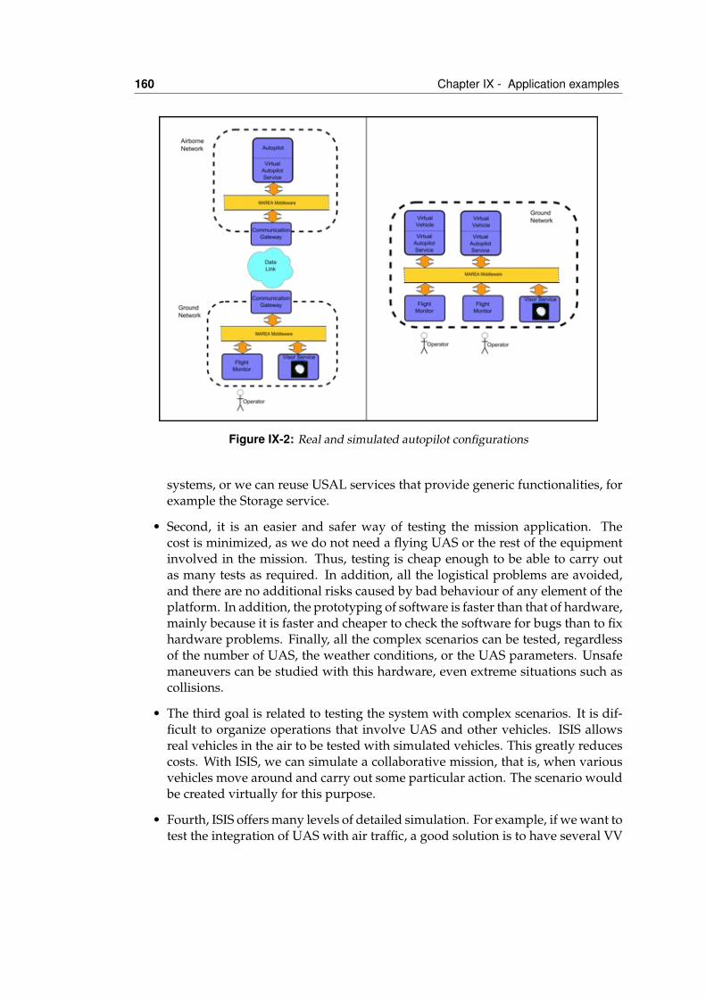
160 Chapter IX - Application examples
Figure IX-2: Real and simulated autopilot configurations
systems, or we can reuse USAL services that provide generic functionalities, forexample the Storage service.
• Second, it is an easier and safer way of testing the mission application. Thecost is minimized, as we do not need a flying UAS or the rest of the equipmentinvolved in the mission. Thus, testing is cheap enough to be able to carry outas many tests as required. In addition, all the logistical problems are avoided,and there are no additional risks caused by bad behaviour of any element of theplatform. In addition, the prototyping of software is faster than that of hardware,mainly because it is faster and cheaper to check the software for bugs than to fixhardware problems. Finally, all the complex scenarios can be tested, regardlessof the number of UAS, the weather conditions, or the UAS parameters. Unsafemaneuvers can be studied with this hardware, even extreme situations such ascollisions.
• The third goal is related to testing the system with complex scenarios. It is dif-ficult to organize operations that involve UAS and other vehicles. ISIS allowsreal vehicles in the air to be tested with simulated vehicles. This greatly reducescosts. With ISIS, we can simulate a collaborative mission, that is, when variousvehicles move around and carry out some particular action. The scenario wouldbe created virtually for this purpose.
• Fourth, ISIS offers many levels of detailed simulation. For example, if we want totest the integration of UAS with air traffic, a good solution is to have several VV
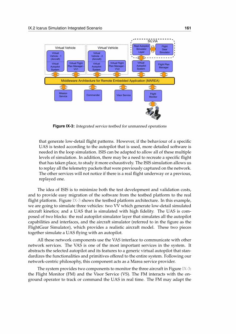
IX.2 Icarus Simulation Integrated Scenario 161
Figure IX-3: Integrated service testbed for unmanned operations
that generate low-detail flight patterns. However, if the behaviour of a specificUAS is tested according to the autopilot that is used, more detailed software isneeded in the loop simulation. ISIS can be adapted to allow all of these multiplelevels of simulation. In addition, there may be a need to recreate a specific flightthat has taken place, to study it more exhaustively. The ISIS simulation allows usto replay all the telemetry packets that were previously captured on the network.The other services will not notice if there is a real flight underway or a previous,replayed one.
The idea of ISIS is to minimize both the test development and validation costs,and to provide easy migration of the software from the testbed platform to the realflight platform. Figure IX-3 shows the testbed platform architecture. In this example,we are going to simulate three vehicles: two VV which generate low-detail simulatedaircraft kinetics; and a UAS that is simulated with high fidelity. The UAS is com-posed of two blocks: the real autopilot simulator layer that simulates all the autopilotcapabilities and interfaces, and the aircraft simulator (referred to in the figure as theFlightGear Simulator), which provides a realistic aircraft model. These two piecestogether simulate a UAS flying with an autopilot.
All these network components use the VAS interface to communicate with othernetwork services. The VAS is one of the most important services in the system. Itabstracts the selected autopilot and its features to a generic virtual autopilot that stan-dardizes the functionalities and primitives offered to the entire system. Following ournetwork-centric philosophy, this component acts as a Marea service provider.
The system provides two components to monitor the three aircraft in Figure IX-3:the Flight Monitor (FM) and the Visor Service (VS). The FM interacts with the on-ground operator to track or command the UAS in real time. The FM may adapt the
162 Chapter IX - Application examples
functionalities according to the operator’s profile: pilot-oriented, central controller-oriented, dispatcher-oriented and maintenance-oriented. To be useful for differentusers, the FM is divided into several interchangeable tools.
The flight planning capabilities of all autopilots are dissimilar, but are generallylimited to simple waypoint navigation. In some cases, they include automatic take-off and landing modes. This simple waypoint-based flight plan may be extremelyrestrictive for current UAS applications. The Flight Plan Manager Service (FPMS) hasbeen designed to implement much richer flight plan capabilities on top of the avail-able capabilities offered by the actual autopilot. The FPMS offers an almost unlimitednumber of waypoints, waypoint grouping, structured flight plan phases with built-in emergency alternatives, mission-oriented legs with a high semantic level such asrepetitions, parameterized scans, etc. These waypoints can be modified by other ser-vices in the UAS by changing a number of configuration parameters, without havingto redesign the actual flight plan. This truly allows cooperation between the autopilotoperation and the specific UAS mission services.
All these flight planning capabilities are represented in the virtual world throughthe Virtual Flight Plan Manager Service (VFPMS). This acts as the FPMS. However, inthis case, the VFPMS is in charge of the VV flight planning capabilities. The VFPMScan be found next to the VAS with VV in Figure IX-3. In addition, the Commander isintroduced. This service operates as the console of the VFPMS. It manages and com-mands the VV flight plan and change the VAS state through the VFPMS. The Com-mander provides the opportunity to control all the VV together in the same console.
Finally, Figure IX-3 shows a Mission Service. Different missions may need differ-ent environment simulators. For example, a Farsite(Finney, 1998) fire simulator canbe used to provide a realistic fire forest environment for fire management missions. Inaddition, additional services to those provided by the USAL may be required onboardand on ground to implement a specific mission. All these services are representedin the figure by a generic Mission Service. They can exploit the autopilot telemetry,interact with the UAS flight path in real time with the FPMS or prepare a collaborativemission with several VV. All these movements and feedback information will bemonitored with FM and the VS.
One of the basic ideas of the USAL architecture is the freedom to add or removeservices from the final solution. The service blocks that are used vary depending onwhich mission the UAS is going to carry out. Some basic services should always bepresent. Other services may differ depending on the mission objectives. In this sec-tion, we have introduced all the services in the ISIS system. There is a more detailedexplanation of the functionalities and features of each service in the following sections.
IX.2.3 The virtual autopilot systemThere are now many autopilot manufacturers in the commercial market that are suit-able for small UAS. Several autopilot configurations exist with a wide variety of se-
IX.2 Icarus Simulation Integrated Scenario 163
lected sensors, sizes, control algorithms and operational capabilities. However, select-ing the right autopilot to be integrated into a given UAS is a complex task, as noneof them are mutually compatible. Moving from one autopilot to another implies achange in features. Consequently, it involves redesigning from scratch all the remain-ing avionics in the UAS. Therefore, once an autopilot has been selected, it may remainin the system throughout its operational life.
The idea is to abstract the autopilot from the rest of the system through a virtualautopilot. Thus, the system interacts with this virtual interface only. When the au-topilot is changed, all the USAL services will continue to work without detecting anychange at all.
The Virtual Autopilot Service (VAS) interacts with the Marea middleware andwith the selected autopilot, and therefore needs to be adapted to the autopilot fea-tures. For other services in the UAS, the VAS is a service provider that offers a numberof information streams that they can consume. With this architecture, all the otherservices in the UAS deal only with the data published by the virtual autopilot, with-out any dependence on the real autopilot. Different VAS implementations will havethe same features, regardless of which underlying autopilot is used. This enables theautopilot capabilities to be generalized and extended.
The autopilot unit can be replaced by a new version or by a different product,but this change will have no impact on the system except to one of the VAS layers.Figure IX-4 shows this behaviour. Another important motivation is to provide anincreased level of functionality. VAS should permit operation with a virtually infinitenumber of waypoints, thus overcoming a limitation that is present in all of the studiedUAS autopilots. It can also check the plausibility of these waypoints. This increasedlevel of functionality includes the ability to take control of the flight and generatenew waypoints in response to contingencies when the services that are in charge ofnavigation control fail.
To test the VAS functionalities, hardware-in-the-loop is needed to simulate theautopilot behaviour when the UAS is not required to fly. A specific autopilot providermay not offer this simulation block. To solve this problem, we have developed anextra piece of software called the Adapter. This program will deal with an aircraftsimulator (i.e FlightGear or X-Plane) and format all the data to the proper semanticsof the specific autopilot. The VAS should not realize whether it is working with theplane and the aircraft or the aircraft simulator and the Adapter. The more the Adapterreassembles the autopilot, the fewer modifications are required when autopilots areinterchanged. Both simulation blocks form the Software-in-the-Loop VAS InterfaceAdapter (SILVIA), as shown in Figure IX-4.
VAS also has its own autopilot states, which means that state information is alsoabstracted. However, not every autopilot works with states. In those that do, thestates may differ from each other. Therefore, the abstraction allows the VAS to publishVAS state information, regardless of whether the autopilot supports it or not. The keyto carrying out a correct abstraction is to offer the common functionality in the VASinterface and provide data that can be found in any autopilot. This information is
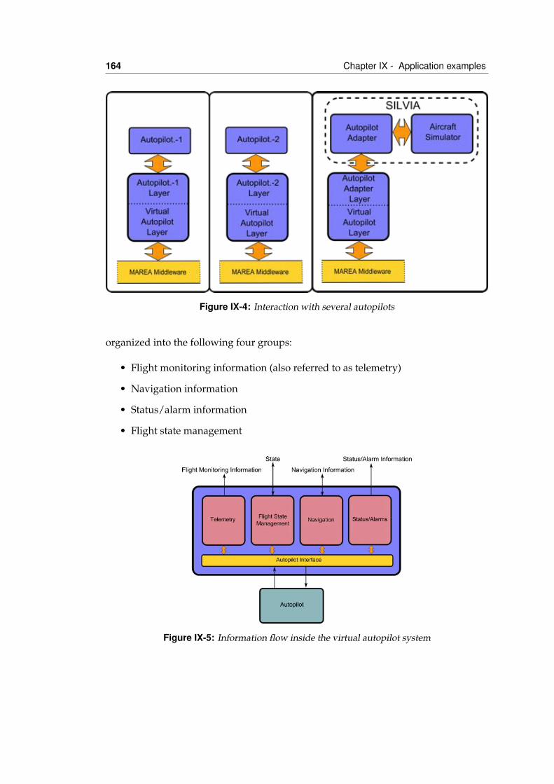
164 Chapter IX - Application examples
Figure IX-4: Interaction with several autopilots
organized into the following four groups:
• Flight monitoring information (also referred to as telemetry)
• Navigation information
• Status/alarm information
• Flight state management
Figure IX-5: Information flow inside the virtual autopilot system
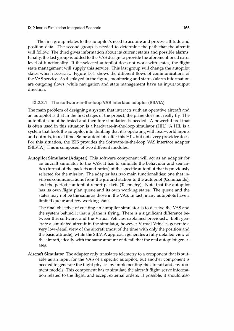
IX.2 Icarus Simulation Integrated Scenario 165
The first group relates to the autopilot’s need to acquire and process attitude andposition data. The second group is needed to determine the path that the aircraftwill follow. The third gives information about its current status and possible alarms.Finally, the last group is added to the VAS design to provide the aforementioned extralevel of functionality. If the selected autopilot does not work with states, the flightstate management will supply this service. This last group will change the autopilotstates when necessary. Figure IX-5 shows the different flows of communications ofthe VAS service. As displayed in the figure, monitoring and status/alarm informationare outgoing flows, while navigation and state management have an input/outputdirection.
IX.2.3.1 The software-in-the-loop VAS interface adapter (SILVIA)
The main problem of designing a system that interacts with an operative aircraft andan autopilot is that in the first stages of the project, the plane does not really fly. Theautopilot cannot be tested and therefore simulation is needed. A powerful tool thatis often used in this situation is a hardware-in-the-loop simulator (HIL). A HIL is asystem that fools the autopilot into thinking that it is operating with real-world inputsand outputs, in real time. Some autopilots offer this HIL, but not every provider does.For this situation, the ISIS provides the Software-in-the-loop VAS interface adapter(SILVIA). This is composed of two different modules:
Autopilot Simulator (Adapter) This software component will act as an adapter foran aircraft simulator to the VAS. It has to simulate the behaviour and seman-tics (format of the packets and ratios) of the specific autopilot that is previouslyselected for the mission. The adapter has two main functionalities: one that in-volves communications from the ground station to the autopilot (Commands),and the periodic autopilot report packets (Telemetry). Note that the autopilothas its own flight plan queue and its own working states. The queue and thestates may not be the same as those in the VAS. In fact, many autopilots have alimited queue and few working states.
The final objective of creating an autopilot simulator is to deceive the VAS andthe system behind it that a plane is flying. There is a significant difference be-tween this software, and the Virtual Vehicles explained previously. Both gen-erate a simulated aircraft in the simulator, however Virtual Vehicles generate avery low-detail view of the aircraft (most of the time with only the position andthe basic attitude), while the SILVIA approach generates a fully detailed view ofthe aircraft, ideally with the same amount of detail that the real autopilot gener-ates.
Aircraft Simulator The adapter only translates telemetry to a component that is suit-able as an input for the VAS of a specific autopilot, but another component isneeded to generate the flight physics by implementing the aircraft and environ-ment models. This component has to simulate the aircraft flight, serve informa-tion related to the flight, and accept external orders. If possible, it should also
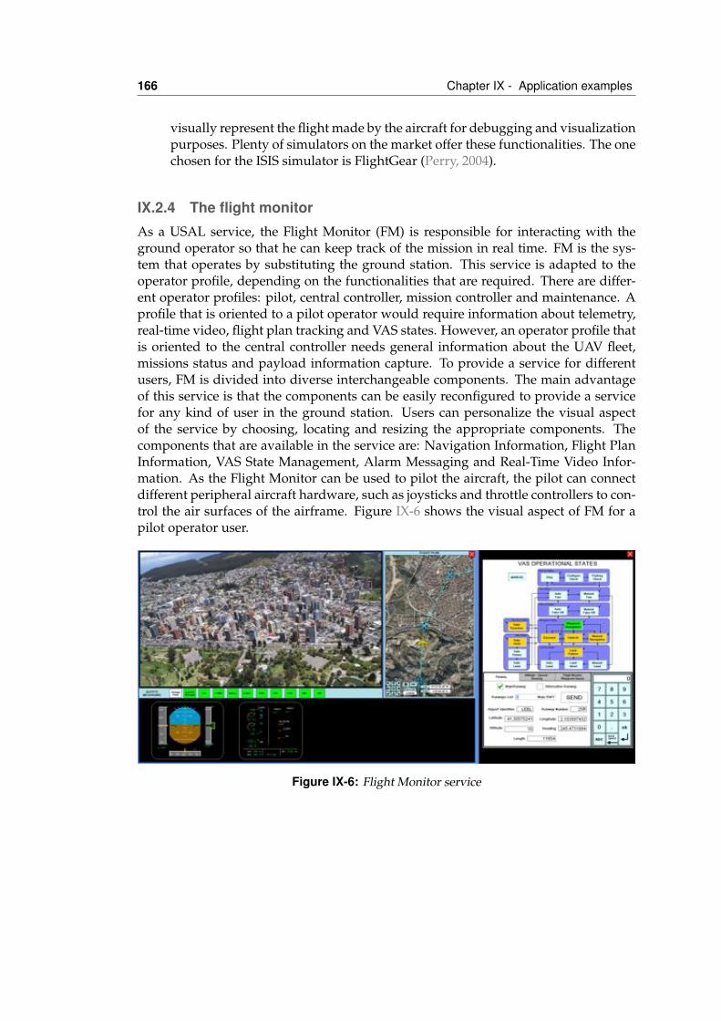
166 Chapter IX - Application examples
visually represent the flight made by the aircraft for debugging and visualizationpurposes. Plenty of simulators on the market offer these functionalities. The onechosen for the ISIS simulator is FlightGear (Perry, 2004).
IX.2.4 The flight monitorAs a USAL service, the Flight Monitor (FM) is responsible for interacting with theground operator so that he can keep track of the mission in real time. FM is the sys-tem that operates by substituting the ground station. This service is adapted to theoperator profile, depending on the functionalities that are required. There are differ-ent operator profiles: pilot, central controller, mission controller and maintenance. Aprofile that is oriented to a pilot operator would require information about telemetry,real-time video, flight plan tracking and VAS states. However, an operator profile thatis oriented to the central controller needs general information about the UAV fleet,missions status and payload information capture. To provide a service for differentusers, FM is divided into diverse interchangeable components. The main advantageof this service is that the components can be easily reconfigured to provide a servicefor any kind of user in the ground station. Users can personalize the visual aspectof the service by choosing, locating and resizing the appropriate components. Thecomponents that are available in the service are: Navigation Information, Flight PlanInformation, VAS State Management, Alarm Messaging and Real-Time Video Infor-mation. As the Flight Monitor can be used to pilot the aircraft, the pilot can connectdifferent peripheral aircraft hardware, such as joysticks and throttle controllers to con-trol the air surfaces of the airframe. Figure IX-6 shows the visual aspect of FM for apilot operator user.
Figure IX-6: Flight Monitor service
IX.2 Icarus Simulation Integrated Scenario 167
IX.2.4.1 Navigation information
The Navigation Information tool is an electronic information system (EIS) that dis-plays information related to telemetry, navigation and electrical aspects. This toolis divided into two subsystems: the Electronic Flight Instrument System (EFIS) andthe Electronic Centralized Aircraft Monitor (ECAM). The EFIS is responsible for thedisplay of the UAV attitude that is generated by the UAV’s telemetry. The FM sub-scribes to this information in the Marea middleware. To increase understanding ofthe telemetry, it is shown in two different displays that are similar to the Airbus 320controls. The first display is the Primary Flight Display (PFD), which provides thefollowing information to the onground crew: attitude and guidance, airspeed, alti-tude and vertical speed, and heading and track. The second display is the NavigationDisplay (ND), which provides navigation data. The ECAM subsystem gives informa-tion to the operator about the UAV’s engine and electrical systems. Under normalconditions, the information displayed on the ECAM is based on the “need to know”philosophy, meaning that the operator is only shown the relevant information for eachflight phase.
IX.2.4.2 Flight plan information
The Flight Monitor has another component that is responsible for keeping track of theestablished flight plan. This component has a similar appearance to navigator maps,and also incorporates all the navigation tools as zoom and movements. Using con-figurable symbols, the flight plan is displayed over the map. By default, the entireflight plan is showed, but the operator can filter it by parts or by waypoints and tra-jectories, to display the most interesting parts for each flight phase. The operator canalso access all the flight plan components if he/she wants to obtain more detailed in-formation. The flight plan can contain too much information to be shown in a smallcomponent, so this component has access to a full-size window mode. Figure IX-7shows the appearance of the Flight Plan Information Component in its compressedmode. The Flight Plan component is subscribed to positioning telemetry to show theUAV position over the flight plan. The Cartography Manager is related to this com-ponent, as it is responsible for managing the available cartography database. Thismanager generates a database with information about cartographic layers and geopo-sitioning data. When a new flight plan is loaded, the manager inspects it and offersthe operator the cartographic layers that are available over the flight plan area.
IX.2.4.3 VAS state management
The pilot operator always needs to know the VAS state, so that he can act on it ifnecessary. The FM tool has a display with all the VAS states. This menu providesinformation about the current state, the available transitions from this state, and thetransitions that are not available. When the operator changes the state, FM informsVAS of the new state. However, it does not show this state until it has received con-firmation. Each state has its own pull-down panel of information on which the usercan modify state parameters, for example, bearings, runways, waypoints, etc. can be
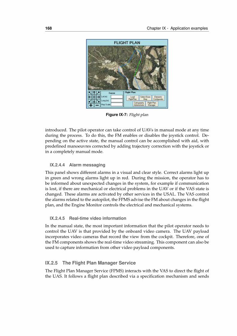
168 Chapter IX - Application examples
Figure IX-7: Flight plan
introduced. The pilot operator can take control of UAVs in manual mode at any timeduring the process. To do this, the FM enables or disables the joystick control. De-pending on the active state, the manual control can be accomplished with aid, withpredefined manoeuvres corrected by adding trajectory correction with the joystick orin a completely manual mode.
IX.2.4.4 Alarm messaging
This panel shows different alarms in a visual and clear style. Correct alarms light upin green and wrong alarms light up in red. During the mission, the operator has tobe informed about unexpected changes in the system, for example if communicationis lost, if there are mechanical or electrical problems in the UAV or if the VAS state ischanged. These alarms are activated by other services in the USAL. The VAS controlthe alarms related to the autopilot, the FPMS advise the FM about changes in the flightplan, and the Engine Monitor controls the electrical and mechanical systems.
IX.2.4.5 Real-time video information
In the manual state, the most important information that the pilot operator needs tocontrol the UAV is that provided by the onboard video camera. The UAV payloadincorporates video cameras that record the view from the cockpit. Therefore, one ofthe FM components shows the real-time video streaming. This component can also beused to capture information from other video payload components.
IX.2.5 The Flight Plan Manager ServiceThe Flight Plan Manager Service (FPMS) interacts with the VAS to direct the flight ofthe UAS. It follows a flight plan described via a specification mechanism and sends
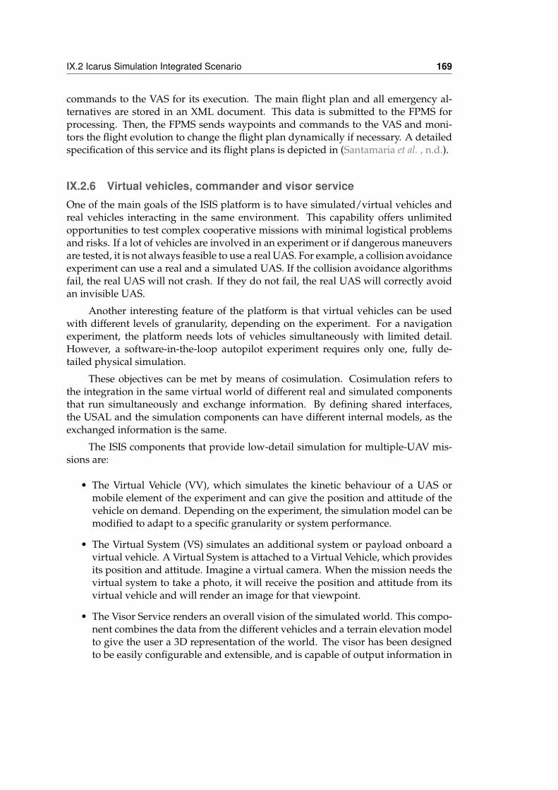
IX.2 Icarus Simulation Integrated Scenario 169
commands to the VAS for its execution. The main flight plan and all emergency al-ternatives are stored in an XML document. This data is submitted to the FPMS forprocessing. Then, the FPMS sends waypoints and commands to the VAS and moni-tors the flight evolution to change the flight plan dynamically if necessary. A detailedspecification of this service and its flight plans is depicted in (Santamaria et al. , n.d.).
IX.2.6 Virtual vehicles, commander and visor serviceOne of the main goals of the ISIS platform is to have simulated/virtual vehicles andreal vehicles interacting in the same environment. This capability offers unlimitedopportunities to test complex cooperative missions with minimal logistical problemsand risks. If a lot of vehicles are involved in an experiment or if dangerous maneuversare tested, it is not always feasible to use a real UAS. For example, a collision avoidanceexperiment can use a real and a simulated UAS. If the collision avoidance algorithmsfail, the real UAS will not crash. If they do not fail, the real UAS will correctly avoidan invisible UAS.
Another interesting feature of the platform is that virtual vehicles can be usedwith different levels of granularity, depending on the experiment. For a navigationexperiment, the platform needs lots of vehicles simultaneously with limited detail.However, a software-in-the-loop autopilot experiment requires only one, fully de-tailed physical simulation.
These objectives can be met by means of cosimulation. Cosimulation refers tothe integration in the same virtual world of different real and simulated componentsthat run simultaneously and exchange information. By defining shared interfaces,the USAL and the simulation components can have different internal models, as theexchanged information is the same.
The ISIS components that provide low-detail simulation for multiple-UAV mis-sions are:
• The Virtual Vehicle (VV), which simulates the kinetic behaviour of a UAS ormobile element of the experiment and can give the position and attitude of thevehicle on demand. Depending on the experiment, the simulation model can bemodified to adapt to a specific granularity or system performance.
• The Virtual System (VS) simulates an additional system or payload onboard avirtual vehicle. A Virtual System is attached to a Virtual Vehicle, which providesits position and attitude. Imagine a virtual camera. When the mission needs thevirtual system to take a photo, it will receive the position and attitude from itsvirtual vehicle and will render an image for that viewpoint.
• The Visor Service renders an overall vision of the simulated world. This compo-nent combines the data from the different vehicles and a terrain elevation modelto give the user a 3D representation of the world. The visor has been designedto be easily configurable and extensible, and is capable of output information in
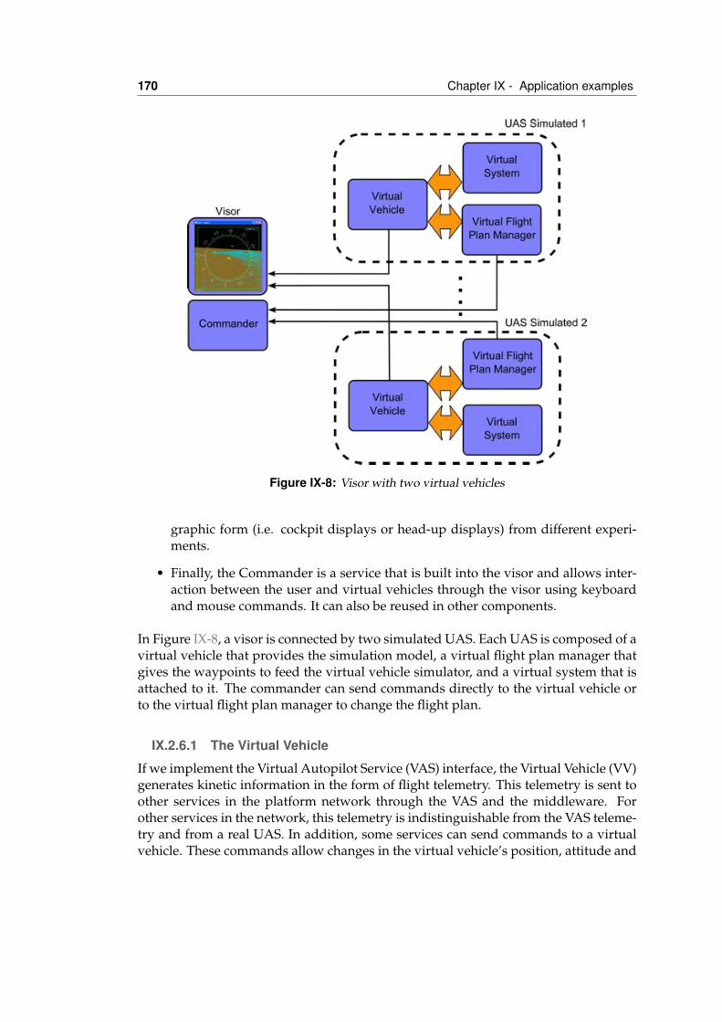
170 Chapter IX - Application examples
Figure IX-8: Visor with two virtual vehicles
graphic form (i.e. cockpit displays or head-up displays) from different experi-ments.
• Finally, the Commander is a service that is built into the visor and allows inter-action between the user and virtual vehicles through the visor using keyboardand mouse commands. It can also be reused in other components.
In Figure IX-8, a visor is connected by two simulated UAS. Each UAS is composed of avirtual vehicle that provides the simulation model, a virtual flight plan manager thatgives the waypoints to feed the virtual vehicle simulator, and a virtual system that isattached to it. The commander can send commands directly to the virtual vehicle orto the virtual flight plan manager to change the flight plan.
IX.2.6.1 The Virtual Vehicle
If we implement the Virtual Autopilot Service (VAS) interface, the Virtual Vehicle (VV)generates kinetic information in the form of flight telemetry. This telemetry is sent toother services in the platform network through the VAS and the middleware. Forother services in the network, this telemetry is indistinguishable from the VAS teleme-try and from a real UAS. In addition, some services can send commands to a virtualvehicle. These commands allow changes in the virtual vehicle’s position, attitude and
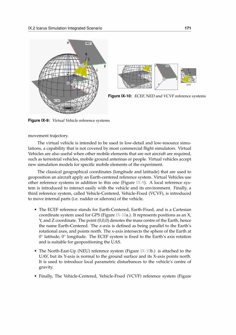
IX.2 Icarus Simulation Integrated Scenario 171
Figure IX-9: Virtual Vehicle reference systems
Figure IX-10: ECEF, NED and VCVF reference systems
movement trajectory.
The virtual vehicle is intended to be used in low-detail and low-resource simu-lations, a capability that is not covered by most commercial flight simulators. VirtualVehicles are also useful when other mobile elements that are not aircraft are required,such as terrestrial vehicles, mobile ground antennas or people. Virtual vehicles acceptnew simulation models for specific mobile elements of the experiment.
The classical geographical coordinates (longitude and latitude) that are used togeoposition an aircraft apply an Earth-centered reference system. Virtual Vehicles useother reference systems in addition to this one (Figure IX-9). A local reference sys-tem is introduced to interact easily with the vehicle and its environment. Finally, athird reference system, called Vehicle-Centered, Vehicle-Fixed (VCVF), is introducedto move internal parts (i.e. rudder or ailerons) of the vehicle.
• The ECEF reference stands for Earth-Centered, Earth-Fixed, and is a Cartesiancoordinate system used for GPS (Figure IX-10a.). It represents positions as an X,Y, and Z coordinate. The point (0,0,0) denotes the mass centre of the Earth, hencethe name Earth-Centered. The z-axis is defined as being parallel to the Earth’srotational axes, and points north. The x-axis intersects the sphere of the Earth at0◦ latitude, 0◦ longitude. The ECEF system is fixed to the Earth’s axis rotationand is suitable for geopositioning the UAS.
• The North-East-Up (NEU) reference system (Figure IX-10b.) is attached to theUAV, but its Y-axis is normal to the ground surface and its X-axis points north.It is used to introduce local parametric disturbances to the vehicle’s centre ofgravity.
• Finally, The Vehicle-Centered, Vehicle-Fixed (VCVF) reference system (Figure
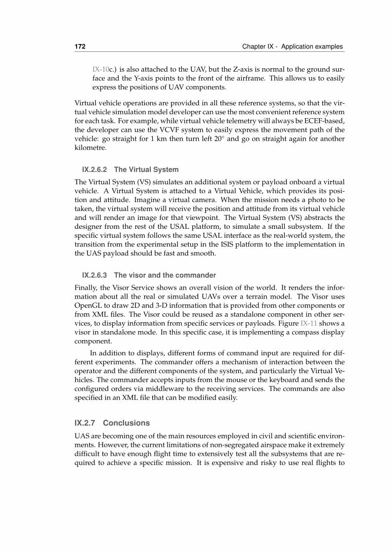
172 Chapter IX - Application examples
IX-10c.) is also attached to the UAV, but the Z-axis is normal to the ground sur-face and the Y-axis points to the front of the airframe. This allows us to easilyexpress the positions of UAV components.
Virtual vehicle operations are provided in all these reference systems, so that the vir-tual vehicle simulation model developer can use the most convenient reference systemfor each task. For example, while virtual vehicle telemetry will always be ECEF-based,the developer can use the VCVF system to easily express the movement path of thevehicle: go straight for 1 km then turn left 20◦ and go on straight again for anotherkilometre.
IX.2.6.2 The Virtual System
The Virtual System (VS) simulates an additional system or payload onboard a virtualvehicle. A Virtual System is attached to a Virtual Vehicle, which provides its posi-tion and attitude. Imagine a virtual camera. When the mission needs a photo to betaken, the virtual system will receive the position and attitude from its virtual vehicleand will render an image for that viewpoint. The Virtual System (VS) abstracts thedesigner from the rest of the USAL platform, to simulate a small subsystem. If thespecific virtual system follows the same USAL interface as the real-world system, thetransition from the experimental setup in the ISIS platform to the implementation inthe UAS payload should be fast and smooth.
IX.2.6.3 The visor and the commander
Finally, the Visor Service shows an overall vision of the world. It renders the infor-mation about all the real or simulated UAVs over a terrain model. The Visor usesOpenGL to draw 2D and 3-D information that is provided from other components orfrom XML files. The Visor could be reused as a standalone component in other ser-vices, to display information from specific services or payloads. Figure IX-11 shows avisor in standalone mode. In this specific case, it is implementing a compass displaycomponent.
In addition to displays, different forms of command input are required for dif-ferent experiments. The commander offers a mechanism of interaction between theoperator and the different components of the system, and particularly the Virtual Ve-hicles. The commander accepts inputs from the mouse or the keyboard and sends theconfigured orders via middleware to the receiving services. The commands are alsospecified in an XML file that can be modified easily.
IX.2.7 ConclusionsUAS are becoming one of the main resources employed in civil and scientific environ-ments. However, the current limitations of non-segregated airspace make it extremelydifficult to have enough flight time to extensively test all the subsystems that are re-quired to achieve a specific mission. It is expensive and risky to use real flights to
IX.3 RedEye 173
Figure IX-11: Using the Visor to implement a virtual compass component
test the complete UAS mission infrastructure. In addition to these problems, there is acurrent limitation to implementing inter-vehicle coordination and even coordinationwith third party applications, providing additional simulated vehicles or a simulatedenvironment.
In this section, we described a Marea-based system called ISIS that can be usedto simulate UAS civil missions. ISIS provides an environment in which the USAL ser-vices that have already been designed can interact with others that are in the processof being designed. It provides an easier and safer way to test the mission application.Costs are reduced as there is no need for a flying UAS or for the rest of the equipmentinvolved in the mission. That is, ISIS minimizes both the test development and thevalidation cost, and provides easy migration of the software from the testbed plat-form to the real flight platform. With ISIS, a collaborative mission can be simulated,which means that various vehicles move around to carry out particular actions. Thescenario can be virtually created for this purpose and multiple vehicles can be used,with different levels of detail in the simulation.
IX.3 RedEyeThis section introduces a flexible and reusable architecture that is designed to facilitatethe development of helicopter-based wildfire monitoring systems. We are developing
174 Chapter IX - Application examples
a helicopter system for the detection, control and analysis of wildland forest fires inthe Mediterranean area. The design of the proposed system is made up of five maincomponents. Each component will work collaboratively to constitute a platform ofhigh added value. The general architecture for wildfire monitoring is being tailored totwo relevant objectives within the particular Mediterranean scenario: day/night firefront evolution, and post-fire hot spot detection.
Due to the complexity of integrating helicopter monitoring for fire front evolutioninto the operation of attack helicopter/airplanes, missions are not currently tackled.The integration of the monitoring vehicle into the rest of the aerial resources is anunsolved problem, both technically and methodologically. However, the operation ofthe monitoring helicopter during certain very well-identified phases of the extinctionprocess is highly plausible.
In addition to monitoring the fire front evolution, the main application that hasbeen considered is the detection of the remaining post-fire hot spots that are locatedat the perimeter of the fire. Just after a fire front has been contained or even duringthe days following extinction, monitoring tasks have to continue, due to the danger offire reactivation. The cost of monitoring with ground or aerial teams is very high andthe process consumes resources that may be needed on other fronts or for concurrentfires. However, a helicopter that is equipped with thermal cameras can fly over thearea and generate a map of hotspots with greater precision at a lower cost. In thisapplication, it is essential that the hotspots are reported immediately, to avoid havingground brigades waiting too long for data. In addition, it is important to feedbackthe information in such a way that it can be consumed effectively, rather than forcingground brigades to walk around the forest without a clear operational scheme.
A heliborne hot spot detection system is being developed on the basis of Mareaservice architecture. This section describes the overall architecture of the system, in-cluding the air segment, the ground control segment, and the interface with the squadsoperating in the fire area, etc. We also demonstrate how the available predefined mod-ules in the SOA architecture have been reused to design this particular application,the additional subsystems that are required to implement specific hot spot missionrequirements, and the overall system / end-user interface.
IX.3.1 MotivationForest fires are a major problem in many countries. Financial loss is the most visibleimpact in the short term. The ecological damage and the impact on wildlife diversityand climate change are the main long-term losses. In some dramatic cases, humanlives are also lost as a result of forest fire. Between 200,000 and 600,000 ha are burntevery year in Europe. Eighty percent of this area corresponds to Mediterranean forestswith high environmental value.
Figure IX-12(a) shows the total burned surface and the number of registered firesfor the period 1995-2004 in France, Greece, Italy, Portugal and Spain. The typicalyearly expenditure on forest fire fighting in Mediterranean Europe amounts to over
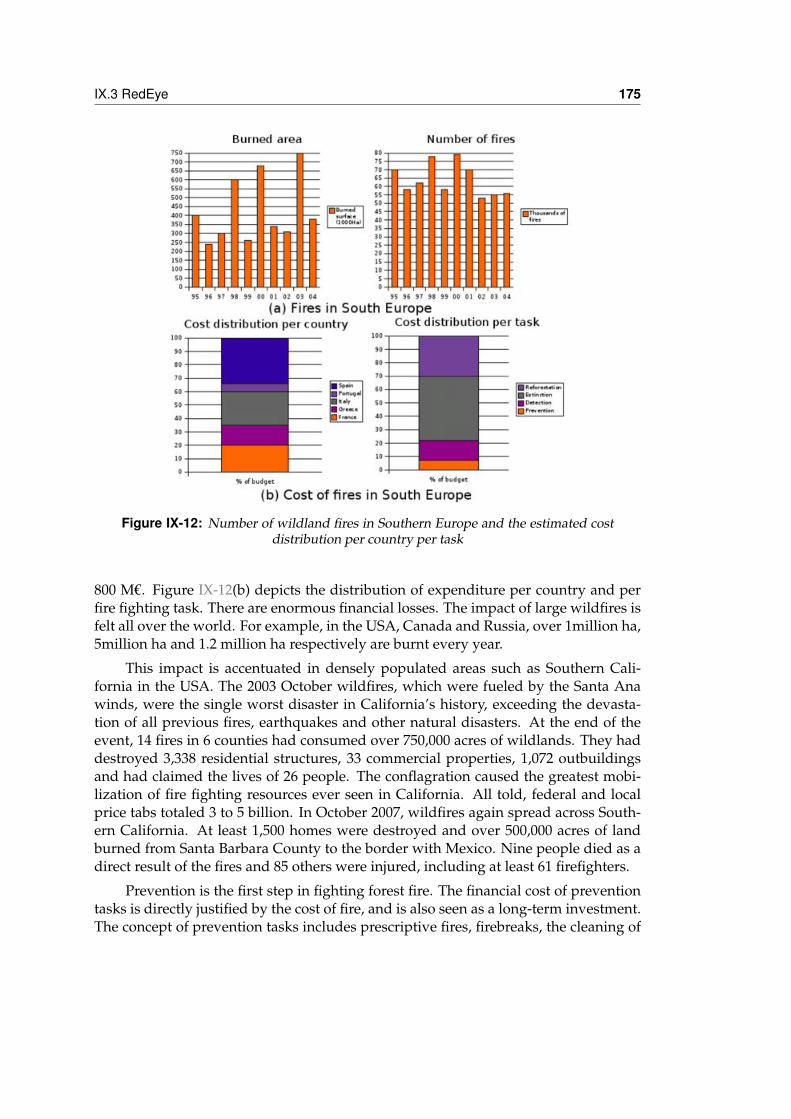
IX.3 RedEye 175
Figure IX-12: Number of wildland fires in Southern Europe and the estimated costdistribution per country per task
800 M€. Figure IX-12(b) depicts the distribution of expenditure per country and perfire fighting task. There are enormous financial losses. The impact of large wildfires isfelt all over the world. For example, in the USA, Canada and Russia, over 1million ha,5million ha and 1.2 million ha respectively are burnt every year.
This impact is accentuated in densely populated areas such as Southern Cali-fornia in the USA. The 2003 October wildfires, which were fueled by the Santa Anawinds, were the single worst disaster in California’s history, exceeding the devasta-tion of all previous fires, earthquakes and other natural disasters. At the end of theevent, 14 fires in 6 counties had consumed over 750,000 acres of wildlands. They haddestroyed 3,338 residential structures, 33 commercial properties, 1,072 outbuildingsand had claimed the lives of 26 people. The conflagration caused the greatest mobi-lization of fire fighting resources ever seen in California. All told, federal and localprice tabs totaled 3 to 5 billion. In October 2007, wildfires again spread across South-ern California. At least 1,500 homes were destroyed and over 500,000 acres of landburned from Santa Barbara County to the border with Mexico. Nine people died as adirect result of the fires and 85 others were injured, including at least 61 firefighters.
Prevention is the first step in fighting forest fire. The financial cost of preventiontasks is directly justified by the cost of fire, and is also seen as a long-term investment.The concept of prevention tasks includes prescriptive fires, firebreaks, the cleaning of
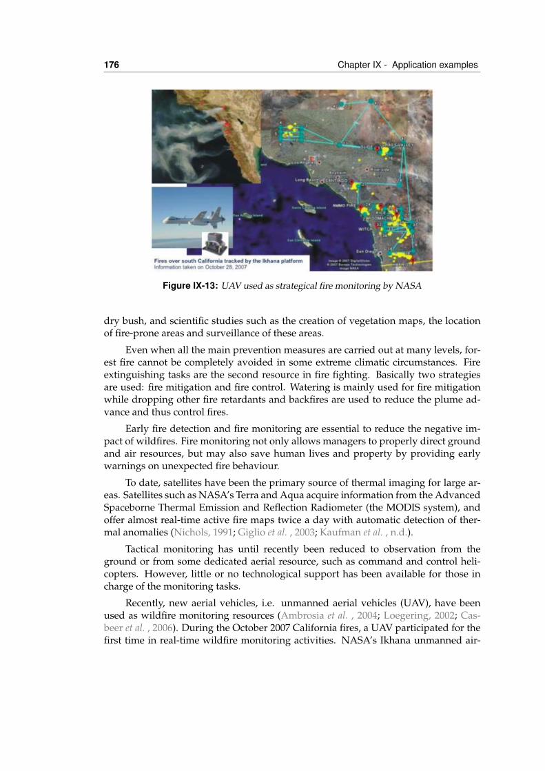
176 Chapter IX - Application examples
Figure IX-13: UAV used as strategical fire monitoring by NASA
dry bush, and scientific studies such as the creation of vegetation maps, the locationof fire-prone areas and surveillance of these areas.
Even when all the main prevention measures are carried out at many levels, for-est fire cannot be completely avoided in some extreme climatic circumstances. Fireextinguishing tasks are the second resource in fire fighting. Basically two strategiesare used: fire mitigation and fire control. Watering is mainly used for fire mitigationwhile dropping other fire retardants and backfires are used to reduce the plume ad-vance and thus control fires.
Early fire detection and fire monitoring are essential to reduce the negative im-pact of wildfires. Fire monitoring not only allows managers to properly direct groundand air resources, but may also save human lives and property by providing earlywarnings on unexpected fire behaviour.
To date, satellites have been the primary source of thermal imaging for large ar-eas. Satellites such as NASA’s Terra and Aqua acquire information from the AdvancedSpaceborne Thermal Emission and Reflection Radiometer (the MODIS system), andoffer almost real-time active fire maps twice a day with automatic detection of ther-mal anomalies (Nichols, 1991; Giglio et al. , 2003; Kaufman et al. , n.d.).
Tactical monitoring has until recently been reduced to observation from theground or from some dedicated aerial resource, such as command and control heli-copters. However, little or no technological support has been available for those incharge of the monitoring tasks.
Recently, new aerial vehicles, i.e. unmanned aerial vehicles (UAV), have beenused as wildfire monitoring resources (Ambrosia et al. , 2004; Loegering, 2002; Cas-beer et al. , 2006). During the October 2007 California fires, a UAV participated for thefirst time in real-time wildfire monitoring activities. NASA’s Ikhana unmanned air-
IX.3 RedEye 177
craft system flew a number of missions over several of the major Southern Californiawildfires from October 24 to October 28, capturing thermal-infrared imagery to aidfirefighters (see Figure 2 for an overview of one of the UAV missions). Ikhana, a Gen-eral Atomics’ Predator B adapted for civil science and technology research missions,flew long-endurance sorties lasting nine to ten hours each from its base at NASA’sDryden Flight Research Center.
Recent developments with increasingly small sensors, both for large aircraft andsatellites, are directly useful for smaller platforms. Most sensors use imaging tech-nologies that include conventional cameras, infra-red/thermal cameras, multispectralcameras, radiometers, Doppler radar and synthetic aperture radar. Small and lightcost-effective conventional and infra-red cameras are available on the COTS marketand can immediately be included in a UAV or a traditional helicopter. The rest ofthe sensor technologies are still too expensive or too heavy to be used onboard theseplatforms, but expected demand will accelerate their miniaturization. In addition,new image processing techniques have been developed and can now be embeddedin small and cheap hardware boards and obtain end-user information in almost realtime.
Nevertheless, a third forest fire fighting task is also needed for surveillance offire embers once the fire has been extinguished. At this time, a considerable amountof terrestrial resources are still devoted to post-fire tasks, especially if the weatherconditions may lead to a fire restarting. The ground crew must continue to watersmoking spots in a typical post-fire situation, and this is frequently done blindly.
The proposed Red Eye system is designed to improve the overall awareness offire managers by providing tactical support for wildfire monitoring and the controlof ground squads (Ononye et al. , 2007; Wright et al. , n.d.). Red Eye is built aroundexisting technology that can immediately be deployed in the field onboard traditionalhelicopters at a reasonable cost. Red Eye is designed to operate from a human on-board the helicopter, and its operation can be integrated into the standard operationof aerial resources. A UAV-based version of Red Eye is currently being developed.However, UAVs have several limitations at the tactical and strategic level that preventtheir widespread use.
IX.3.2 Problem analysis and tactical objectivesDecisions on forest fire management should be taken in relation to the actual fire itself.However, several factors make it difficult for decision-makers to obtain an overall, pre-cise view of the situation (see Figure IX-13 for an illustrative image). Smoke in the areaof the fire interferes with the ability to acquire coherent data about the actual situation.To obtain an overview of the fire, the coordinator should fly over the area, and there-fore has to temporarily leave the control centre. Manned airplanes cannot be usedfor forest-fire control during the night or when smoke is dense, flying time is quitelimited, there are practically no available sensors onboard traditional airplanes, etc.Dangerous situations for fire fighting personnel working on the ground may develop
178 Chapter IX - Application examples
very rapidly.
The current technology that is used to collect information on the operational sit-uation on the ground makes it difficult for a firefighter coordinator to make the rightdecisions in time. A UAV platform that can fly over the area of a forest fire for longperiods of time and can operate from non-prepared terrains would be an extremelyvaluable information gathering asset, which would overcome some of the aforemen-tioned limitations. However, UAVs have extremely high operational limitations dueto the lack of legislation that defines their operational requirements. Meanwhile, atraditional aerial vehicle dedicated to fire monitoring can still offer some advantages:
1. The payload can acquire coherent data even when there is bad weather or envi-ronmental conditions, such as smoke.
2. They can increase access to ubiquitous information and help fire managers totake decisions.
3. They can prevent dangerous situations for onground operators that can evolvevery quickly.
4. They can provide on-the-fly communication links between fire managers andthe ground teams, especially in mountainous or non-covered areas.
The above challenges are not critical for a helicopter with the required technologyon board. The project Red Eye proposes to develop a helicopter-based platform thatcan fly over the surveillance area for as long as is needed and can operate and adapt tomultiple demanding data collection scenarios, due to its embedded computer systems.
As an example of the advantages of the use of the Red Eye system in large areasurveillance, we present two especially important objectives within the specific scenar-ios that were identified with the help of GRAF (Grup de Reforç d’Activitats Forestals),the selected branch of the Catalonia (Spain) Firefighters that is in charge of developingnew operational strategies for wildland fire:
1. Surveillance flights during the day (night flights are not possible in Spain) togather the information required by firefighters to conduct extinction operationsin a timely and effective way.
2. Early morning or late afternoon flights to monitor the evolution of post-fire hotspots during the days following fire extinction.
IX.3.3 Architecture of Red Eye systemsThe design of the proposed Red Eye system is composed of five main components (seeFigure IX-14). Each component will work collaboratively to constitute a platform ofhigh added value:
1. Manned helicopter equipped with a sensor platform and embedded control sys-tem.
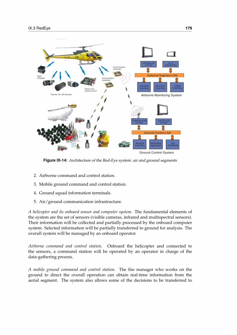
IX.3 RedEye 179
Figure IX-14: Architecture of the Red-Eye system: air and ground segments
2. Airborne command and control station.
3. Mobile ground command and control station.
4. Ground squad information terminals.
5. Air/ground communication infrastructure.
A helicopter and its onboard sensor and computer system. The fundamental elements ofthe system are the set of sensors (visible cameras, infrared and multispectral sensors).Their information will be collected and partially processed by the onboard computersystem. Selected information will be partially transferred to ground for analysis. Theoverall system will be managed by an onboard operator.
Airborne command and control station. Onboard the helicopter and connected tothe sensors, a command station will be operated by an operator in charge of thedata-gathering process.
A mobile ground command and control station. The fire manager who works on theground to direct the overall operation can obtain real-time information from theaerial segment. The system also allows some of the decisions to be transferred to
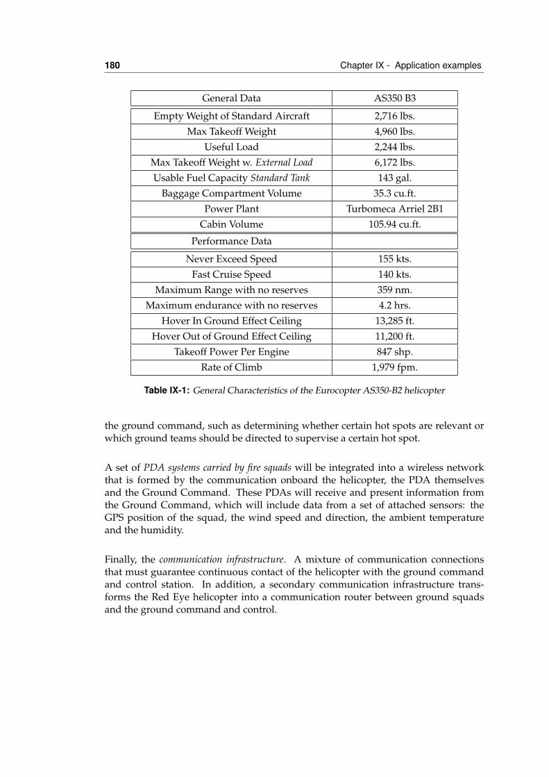
180 Chapter IX - Application examples
General Data AS350 B3
Empty Weight of Standard Aircraft 2,716 lbs.Max Takeoff Weight 4,960 lbs.
Useful Load 2,244 lbs.Max Takeoff Weight w. External Load 6,172 lbs.Usable Fuel Capacity Standard Tank 143 gal.
Baggage Compartment Volume 35.3 cu.ft.Power Plant Turbomeca Arriel 2B1
Cabin Volume 105.94 cu.ft.
Performance Data
Never Exceed Speed 155 kts.Fast Cruise Speed 140 kts.
Maximum Range with no reserves 359 nm.Maximum endurance with no reserves 4.2 hrs.
Hover In Ground Effect Ceiling 13,285 ft.Hover Out of Ground Effect Ceiling 11,200 ft.
Takeoff Power Per Engine 847 shp.Rate of Climb 1,979 fpm.
Table IX-1: General Characteristics of the Eurocopter AS350-B2 helicopter
the ground command, such as determining whether certain hot spots are relevant orwhich ground teams should be directed to supervise a certain hot spot.
A set of PDA systems carried by fire squads will be integrated into a wireless networkthat is formed by the communication onboard the helicopter, the PDA themselvesand the Ground Command. These PDAs will receive and present information fromthe Ground Command, which will include data from a set of attached sensors: theGPS position of the squad, the wind speed and direction, the ambient temperatureand the humidity.
Finally, the communication infrastructure. A mixture of communication connectionsthat must guarantee continuous contact of the helicopter with the ground commandand control station. In addition, a secondary communication infrastructure trans-forms the Red Eye helicopter into a communication router between ground squadsand the ground command and control.
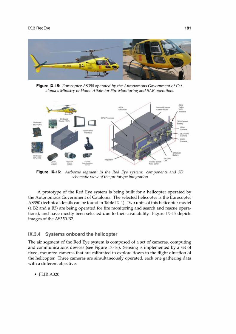
IX.3 RedEye 181
Figure IX-15: Eurocopter AS350 operated by the Autonomous Government of Cat-alonia’s Ministry of Home Affairsfor Fire Monitoring and SAR operations
Figure IX-16: Airborne segment in the Red Eye system: components and 3Dschematic view of the prototype integration
A prototype of the Red Eye system is being built for a helicopter operated bythe Autonomous Government of Catalonia. The selected helicopter is the EurocopterAS350 (technical details can be found in Table IX-1). Two units of this helicopter model(a B2 and a B3) are being operated for fire monitoring and search and rescue opera-tions), and have mostly been selected due to their availability. Figure IX-15 depictsimages of the AS350-B2.
IX.3.4 Systems onboard the helicopterThe air segment of the Red Eye system is composed of a set of cameras, computingand communications devices (see Figure IX-16). Sensing is implemented by a set offixed, mounted cameras that are calibrated to explore down to the flight direction ofthe helicopter. Three cameras are simultaneously operated, each one gathering datawith a different objective:
• FLIR A320
182 Chapter IX - Application examples
– Thermal imaging– Resolution: 16 bit 320x240 pixels– Frame rate: 9 Hz– Connection: Ethernet 100 Mbps
• Lumenera LE11059
– High resolution image– Resolution: 4000 X 2656 pixels– Frame rate: 3 fps at 4000x2656; 8.5 fps at 4000x640– Light sensitivity: 0.1 lux– Connection: Ethernet 100 Mbps
• Lumenera LE350C_DN
– Medium resolution standard image/near infrared– Resolution: 2048x1536 pixels– Frame rate: 10 fps at 2048x1536; 40 fps at 1024x768– Connection: Ethernet 100 Mbps
Images will be acquired by an onboard computer system and stored on the system’shard disk. Visible images are stored for reference, while the thermal image is pro-cessed to identify potential hot spots. Initial filters separate the images that do notcontain significant thermal information from those that contain potential hot spots.If a thermal signature is detected, then the hot spots are identified inside the imageand correlated to other images that are taken immediately after the potential hot spotimage. Potential hot spot images are stored and offered to the onboard operator.
The equipment on the helicopter also contains an IMU plus GPS that providesprecise navigation and real-time orientation of the platform. This information willbe stored and correlated to the image acquisition process. Images will only be geo-allocated if significant thermal signatures are detected. The image processing is notdone in real time, but queued to be executed as soon as possible with the availableCPU capacity. Computation capabilities are implemented through the fanless embed-ded computer VIA EPIA ME6000G. Its main characteristics are:
• CPU: 600MHz Fanless VIA Eden™ Processor
• VGA: Integrated VIA UniChrome™ AGP graphics with MPEG-2 decoding ac-celeration
• 10/100 Mbps Ethernet
• Two serial COM ports for IMU/GPS communication
IX.3 RedEye 183
Internal communications between cameras and the computation module is imple-mented through an onboard RouterBOARD RB532A. Its main characteristics are:
• CPU: MIPS32 4Kc based 266MHz embedded processor
• Memory: 64MB DDR onboard memory chip
• 3 x 10/100 Mbps Ethernet
• 2 x MiniPCI for Wifi and WiMax links.
The Red Eye system will continuously transmit to the ground basic information on theposition of the helicopter and the pictures that have been taken (only the position). Ifthermal signatures are detected, the application will identify these pictures and sched-ule them to be transferred to the ground, if requested. All other pictures will be storedfor post-mission analysis.
Screens and interfaces are also present to implement a control application and toprovide visual cues to the helicopter pilot to guarantee that the flight path correspondsas far as possible to the one that best fits the exploration of the area that is underway.The main control screen is designed to offer access to the monitoring procedures, theflight path monitoring, the acquired images, the position of the ground teams, etc. Thisscreen offer both a touch screen interface and a joystick for precise pointer positioning.
A second small screen is placed in the pilot’s position that provides immediateguidance in terms of correct altitude, heading, lateral displacements, and initial andfinal points with respect to monitoring the flight paths. This screen is only informativeand its information depends on the operational mode that has been selected by thecontroller.
IX.3.5 Service Oriented ImplementationIn terms of software, the Red Eye system is basically a set of Marea services, but someexternal components are added. Figure IX-17 depicts the main components. In themiddle of the figure, the yellow box represents the Marea middleware that intercon-nects the services that make up the system. Six differents services, which are depictedas blue boxes in the figure, provide all the required functionalities for the system. Adistributed external component is needed for this specific application. At the top ofthe picture, a GeoServer is connected to the main Red Eye service. Below, we describethe different services.
GPS Service
This service provides the position and attitude of the helicopter for the rest of thesystem. This information shows the current position on the operator and pilot screensand is used to trigger the onboard camera when the helicopter is hovering a scan point.The service follows the USAL directives and is therefore compatible with the Position
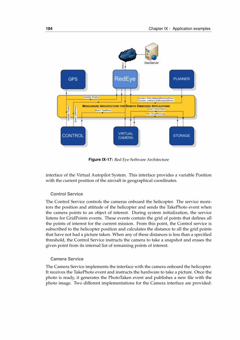
184 Chapter IX - Application examples
Figure IX-17: Red Eye Software Architecture
interface of the Virtual Autopilot System. This interface provides a variable Positionwith the current position of the aircraft in geographical coordinates.
Control Service
The Control Service controls the cameras onboard the helicopter. The service moni-tors the position and attitude of the helicopter and sends the TakePhoto event whenthe camera points to an object of interest. During system initialization, the servicelistens for GridPoints events. These events contain the grid of points that defines allthe points of interest for the current mission. From this point, the Control service issubscribed to the helicopter position and calculates the distance to all the grid pointsthat have not had a picture taken. When any of these distances is less than a specifiedthreshold, the Control Service instructs the camera to take a snapshot and erases thegiven point from its internal list of remaining points of interest.
Camera Service
The Camera Service implements the interface with the camera onboard the helicopter.It receives the TakePhoto event and instructs the hardware to take a picture. Once thephoto is ready, it generates the PhotoTaken event and publishes a new file with thephoto image. Two different implementations for the Camera interface are provided:
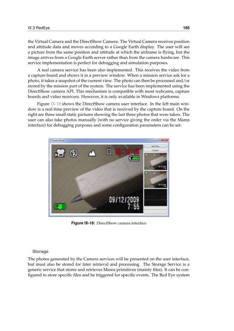
IX.3 RedEye 185
the Virtual Camera and the DirectShow Camera. The Virtual Camera receives positionand attitude data and moves according to a Google Earth display. The user will seea picture from the same position and attitude at which the airframe is flying, but theimage arrives from a Google Earth server rather than from the camera hardware. Thisservice implementation is perfect for debugging and simulation purposes.
A real camera service has been also implemented. This receives the video froma capture board and shows it in a preview window. When a mission service ask for aphoto, it takes a snapshot of the current view. The photo can then be processed and/orstored by the mission part of the system. The service has been implemented using theDirectShow camera API. This mechanism is compatible with most webcams, captureboards and video receivers. However, it is only available in Windows platforms.
Figure IX-18 shows the DirectShow camera user interface. In the left main win-dow is a real-time preview of the video that is received by the capture board. On theright are three small static pictures showing the last three photos that were taken. Theuser can also take photos manually (with no service giving the order via the Mareainterface) for debugging purposes and some configuration parameters can be set.
Figure IX-18: DirectShow camera interface
Storage
The photos generated by the Camera services will be presented on the user interface,but must also be stored for later retrieval and processing. The Storage Service is ageneric service that stores and retrieves Marea primitives (mainly files). It can be con-figured to store specific files and be triggered for specific events. The Red Eye system
186 Chapter IX - Application examples
has been configured to react to the PhotoTaken event. This event carries the URL ofthe file primitive to copy in permanent storage. The Storage Service subscribes to it,and stores all the information, in this case the new photo, in a local file with the corre-sponding date and time mark.
Planner
The Planner Service is an auxiliary service that computes areas and points of interest.It has been implemented as a separate service as this means that its implementationcan be changed and it can easily be reused for different missions. It provides twoMarea functions:
• GetFourthPoint. Given three points that are selected from a map by the user,this function generates a squared area to scan by generating the missing fourthpoint.
• GridPoints. This function computes all the points of interest that should bescanned in an area. The characteristics of the points that are generated, for ex-ample the distance between them on both axes, can be specified at the servicelevel.
Red Eye
This service represents the system’s user interface and is the core of the system. Itgenerates all the graphical information that the operator and the pilot will receive fromthe system, including all the map views. The Red Eye screens use maps to configurewhich areas to scan, to monitor the current flight of the helicopter and to view andvalidate the thermal images that are retrieved automatically by the Camera services.
The user inputs generate events or functions that are processed by other servicesin the system. For example, when the operator defines a new work area, the Red Eyeservice orchestrates the rest of the services in the system to scan the designated area.Its operation will be described in more detail in the next section.
GeoServer
Finally, the GeoServer (Bergmann et al. , 2000) is an external server that provides car-tography, ortophotography and other GIS data to the Red Eye user interfaces. As thehelicopter flies, the system screens update their position and ask the server for addi-tional imagery. The communication between the GeoServer and the Red Eye serviceis carried out using the WMS-C OpenGis Standard (Rocha et al. , 2005). This protocolstandardizes the retrieval of maps and other geographically referenced informationby using a network protocol similar to HTTP. By using this, the Red Eye user interfacecan be easily connected to multiple servers that implement this technology.
IX.3 RedEye 187
IX.3.6 Air and/or ground command systemsThe command and control systems’ software onboard the helicopter and on theground are almost identical. The main difference between them is the latency requiredto obtain the image information. Onboard the helicopter, images can be reviewed assoon as they are acquired (although hot spot detection will require a certain amountof computation time). On the ground, the images can be seen on request. The latencyof the transmission will be much longer and will depend on the distance from thehelicopter to the ground control.
The operation of the command and control software is divided into five phases,namely:
1. System configuration
2. Definition of exploration areas
3. Hot spot exploration
4. Hot spot confirmation
5. Ground squad task assignment
1. System configuration
The system configuration screen allows us to configure the system to define the pre-ferred exploration altitudes and speeds, according to the desired resolution in eachphase of the operation (exploration/confirmation) and the available combination ofcamera/optics.
Information that indicates the location of the ground control station, landing sitesand identification of the available ground squads can also be specified.
Finally, restricted areas can also be specified to indicate population areas that arenot to be directly flown over and/or that have especially dangerous obstacles, such astowers or electric lines.
2. Definition of exploration areas
The areas to be explored need to be specified by the operator by means of a closedpolygon. Each polygon implies at least a separate exploration by the helicopter.
The Red Eye system automatically offers an exploration solution that is definedby a number of trapezoidal areas to be scanned through linear tracks flown over bythe helicopter at the specified distance to the ground. The particular altitude at whichthe helicopter should fly in each pass will depend on variations in the terrain elevation(available through a Digital Elevation Model of the area).
Figure IX-19 shows different views of the application for two exploration areas.The main direction of the terrain elevation is specified by an arrow annotated withthe average terrain slope. Steep slopes will force perpendicular explorations to avoid
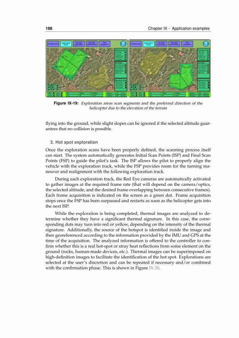
188 Chapter IX - Application examples
Figure IX-19: Exploration areas scan segments and the preferred direction of thehelicopter due to the elevation of the terrain
flying into the ground, while slight slopes can be ignored if the selected altitude guar-antees that no collision is possible.
3. Hot spot exploration
Once the exploration scans have been properly defined, the scanning process itselfcan start. The system automatically generates Initial Scan Points (ISP) and Final ScanPoints (FSP) to guide the pilot’s task. The ISP allows the pilot to properly align thevehicle with the exploration track, while the FSP provides room for the turning ma-neuver and realignment with the following exploration track.
During each exploration track, the Red Eye cameras are automatically activatedto gather images at the required frame rate (that will depend on the camera/optics,the selected altitude, and the desired frame overlapping between consecutive frames).Each frame acquisition is indicated on the screen as a green dot. Frame acquisitionstops once the FSP has been surpassed and restarts as soon as the helicopter gets intothe next ISP.
While the exploration is being completed, thermal images are analyzed to de-termine whether they have a significant thermal signature. In this case, the corre-sponding dots may turn into red or yellow, depending on the intensity of the thermalsignature. Additionally, the source of the hotspot is identified inside the image andthen georeferenced according to the information provided by the IMU and GPS at thetime of the acquisition. The analyzed information is offered to the controller to con-firm whether this is a real hot-spot or stray heat reflections from some element on theground (rocks, human-made devices, etc.). Thermal images can be superimposed onhigh-definition images to facilitate the identification of the hot spot. Explorations areselected at the user’s discretion and can be repeated if necessary and/or combinedwith the confirmation phase. This is shown in Figure IX-20.
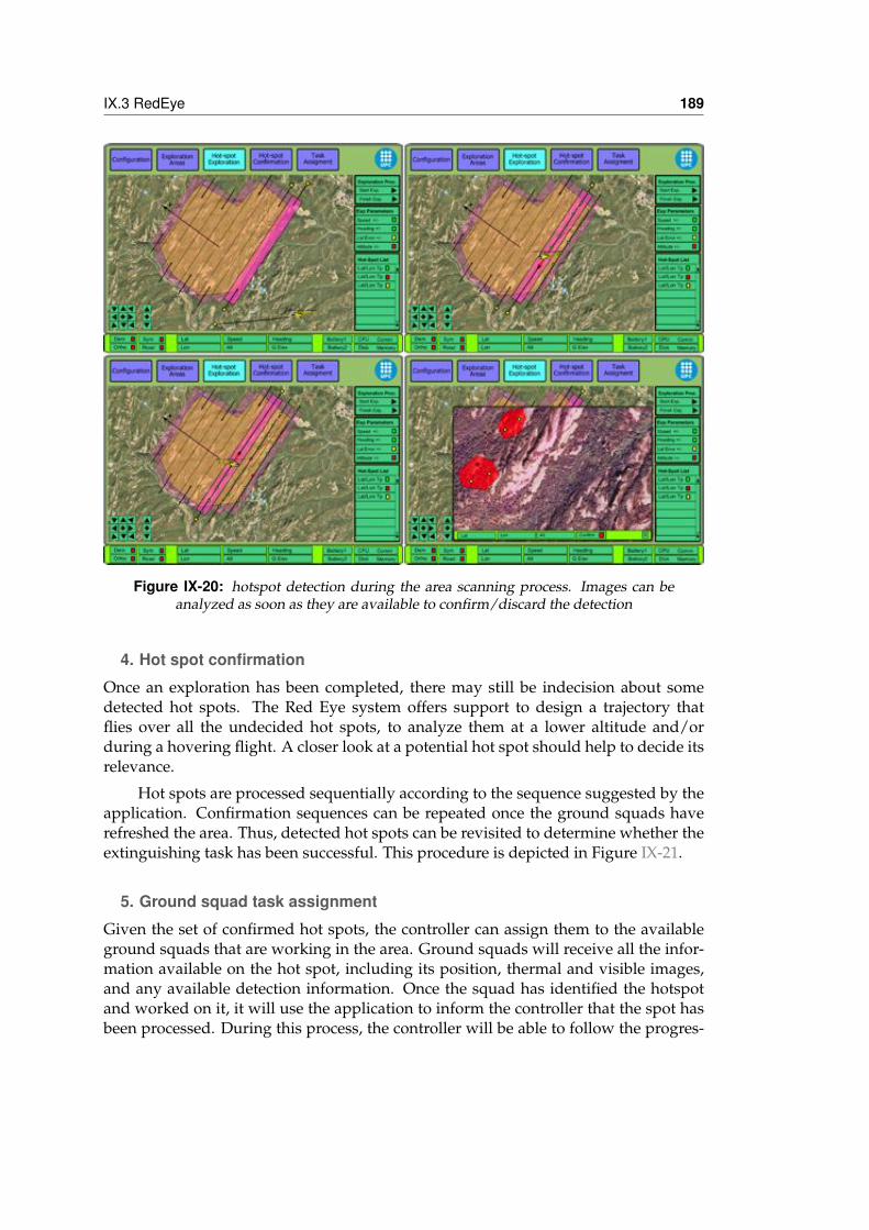
IX.3 RedEye 189
Figure IX-20: hotspot detection during the area scanning process. Images can beanalyzed as soon as they are available to confirm/discard the detection
4. Hot spot confirmation
Once an exploration has been completed, there may still be indecision about somedetected hot spots. The Red Eye system offers support to design a trajectory thatflies over all the undecided hot spots, to analyze them at a lower altitude and/orduring a hovering flight. A closer look at a potential hot spot should help to decide itsrelevance.
Hot spots are processed sequentially according to the sequence suggested by theapplication. Confirmation sequences can be repeated once the ground squads haverefreshed the area. Thus, detected hot spots can be revisited to determine whether theextinguishing task has been successful. This procedure is depicted in Figure IX-21.
5. Ground squad task assignment
Given the set of confirmed hot spots, the controller can assign them to the availableground squads that are working in the area. Ground squads will receive all the infor-mation available on the hot spot, including its position, thermal and visible images,and any available detection information. Once the squad has identified the hotspotand worked on it, it will use the application to inform the controller that the spot hasbeen processed. During this process, the controller will be able to follow the progres-
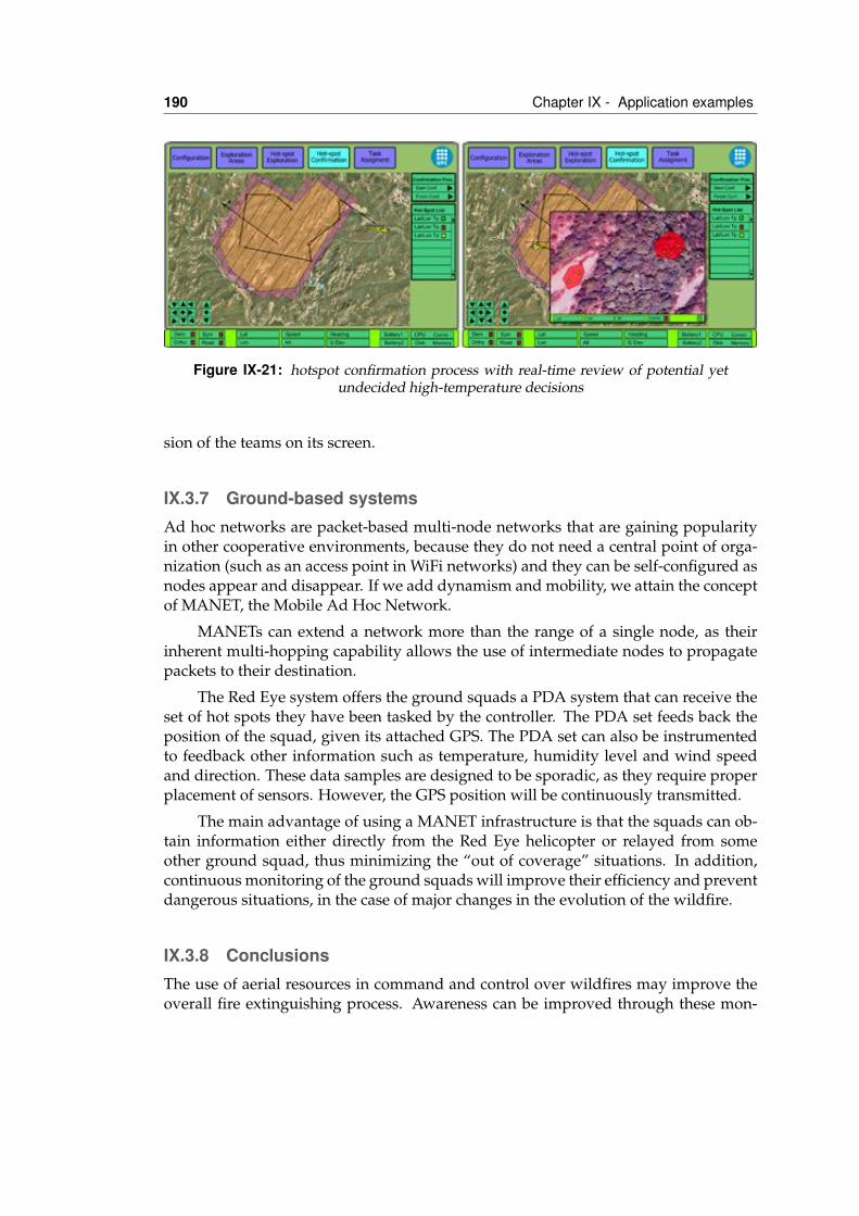
190 Chapter IX - Application examples
Figure IX-21: hotspot confirmation process with real-time review of potential yetundecided high-temperature decisions
sion of the teams on its screen.
IX.3.7 Ground-based systemsAd hoc networks are packet-based multi-node networks that are gaining popularityin other cooperative environments, because they do not need a central point of orga-nization (such as an access point in WiFi networks) and they can be self-configured asnodes appear and disappear. If we add dynamism and mobility, we attain the conceptof MANET, the Mobile Ad Hoc Network.
MANETs can extend a network more than the range of a single node, as theirinherent multi-hopping capability allows the use of intermediate nodes to propagatepackets to their destination.
The Red Eye system offers the ground squads a PDA system that can receive theset of hot spots they have been tasked by the controller. The PDA set feeds back theposition of the squad, given its attached GPS. The PDA set can also be instrumentedto feedback other information such as temperature, humidity level and wind speedand direction. These data samples are designed to be sporadic, as they require properplacement of sensors. However, the GPS position will be continuously transmitted.
The main advantage of using a MANET infrastructure is that the squads can ob-tain information either directly from the Red Eye helicopter or relayed from someother ground squad, thus minimizing the “out of coverage” situations. In addition,continuous monitoring of the ground squads will improve their efficiency and preventdangerous situations, in the case of major changes in the evolution of the wildfire.
IX.3.8 ConclusionsThe use of aerial resources in command and control over wildfires may improve theoverall fire extinguishing process. Awareness can be improved through these mon-
IX.3 RedEye 191
itoring systems, which will maximize the efficiency of the available resources andsimultaneously improve the safety of personnel working on the fire. However, thecomplexity of integrating the monitoring systems together with the traditional aerialresources is a complex task that requires further investigation.
The Red Eye system is a partial solution to this task. Its objective is to providehot spot detection for areas in which other aerial resources have been temporally re-moved. It has been identified by GRAF, a specialized support group that is part ofthe firefighters of Catalonia (Spain). This scenario may have considerable benefits interms of efficiency. Red Eye allows aerial and ground resources to be employed onother fire fronts by reducing the number of resources that need to be kept on the fieldonce a fire front has been controlled.
The Red Eye system has been designed and prototyped and will be tested dur-ing the prescribed fire campaign that is regularly implemented by firefighters in thespring.

XConclusions
During this work some questions arose that were assessed and some of them are stillopen and could be topics of further research. A brief summary and conclusions ofthe achieved results, as well as hints on the possible directions for future work, arepresented in this section.
X.1 Summary of contributionsUAVs are emerging as a valid commercial option that, as many other computer em-bedded systems, has important limitations in space, power consumption, and compu-tation capabilities. The use of current market devices and electronics are mandatoryto keep a low cost solution, while this leads to a distributed architecture. However, webelieve that there is a lack of software support to effectively develop the potentialitiesof unmanned aircraft avionics.
The main thesis of this research is a middleware-based architecture speciallysuited to operate as a flexible mission and payload controller in an UAV. The systemis composed of a number of low-cost distributed computing devices connected by a
193
194 Chapter X - Conclusions
network. The functionality of the system is divided into a set of reusable services thatcan be distributed over the different computing nodes of the network. A middlewaremanages the lifecycle and the communication between services, operating the globalsystem as a Distributed Embedded System.
Seen as a set of applications, the UAV is composed of set of distributed ele-ments, known as services, which operate on top of a middleware communicationframework. The communication primitives are mainly publish-subscribe based,however two-way synchronous communication, i.e. remote procedure calls are alsoavailable for the services. Additional efforts have been placed in some specifics of theUAV avionics domain, in special the interoperation with unreliable and high-latencypoint-to-point networks. Additionally, our view of the system not only comprisesthe hardware onboard a single airplane, but also the ground control station and itspossible extension to include other UAVs. This additional complexity is managed byspecial nodes called communication gateways that act as transparent proxies for allrequired services located in a physically separated fragment of the network.
More specifically, the main objectives of this thesis are:
1. The definition of a system architecture for embedded systems, and the commu-nication requirements for its distributed components.
2. The development and evaluation of a communicating middleware for this archi-tecture.
3. The design of a communication gateway that abstracts and manages the compo-nent communication among nodes in different local networks.
Next sections are going to review the contributions remarks of each main objectives ofthis Doctoral Thesis.
X.1.1 System Architecture ContributionsThe main system architecture contributions are summarized as follows:
• Most of the architectures used for UAS avionics are designed and implementedadhoc for the specific application and platform. One contribution of this workis the definition of a generic service oriented architecture reusable for many en-vironments. The service model has been carefully designed for fulfiling all therequirements detected in civil UAS applications. This study is summarized inchapter III. The service definition and its specification is specified in section IV.2.
• These services are connected with other services for implementing more com-plex behaviours. The connections have different quality of service requirementsdepending on the data they carry. For providing differenciated QoS, four com-munication primitives are provided: variables, events, functions and files. Thiscontribution is depicted in section IV.3.
X.1 Summary of contributions 195
• One important characteristic of the proposed service oriented architecture is thatthe network location of the service is transparent to both the service program-mer and user. Then, an additional mechanism fot identifying the services in thesystem has to be provided. This naming scheme is mostly focused in the serviceinterface, i.e its characteristics, than not in its specific location in the network. Inaddition to this, the naming scheme permits to specify multiple redundant andinterchangeable services and also groups of services providing partitioned data.The proposed naming scheme is described on section IV.4.
X.1.2 Middleware ContributionsThe main middleware contributions are summarized as follows:
• For evaluating the proposed architecture and for having a testbed a completeimplementation of the system has been done. Middleware-based software sys-tems consist of a network of cooperating components, in our case the services,which implement the business logic of the application and an integrating mid-dleware layer that abstracts the execution environment and implements com-mon functionalities and communication channels. Such a system constructionis challenging by itself. In our architecture, the middleware takes the form of acomponent called service container. The services are executed and managed by aservice container that is unique in each node of the distributed system network.The service container can manage several services and provides common func-tionalities (network access, local message delivery, name resolution and caching,etc.) to the services it contains. The middleware design and implementation hasbeen extensibily explained in chapter V.
• The proposed service oriented architecture can be seen as a modular avionics ar-chitecture for UAS. To be operative, this architecture definition and abstractionlayer also need a definition of the operations and procedures to convert a set of“standardized” services into a flyable and operational system. The full processhas been divided in two different steps: dispatching and startup.Dispatchinginvolves all the configuration steps from selecting the aircraft and the payload,defining the mission and the flight-plan to cross-checking all the interdepen-dencies and restrictions between these items. The next step, startup, involvesallocating the services among the selected hardware and finally deploying allthe software services and its associated files to the assigned nodes. The pro-posed configuration and deployment infrastructure and its related proceduresthat complete our vision of UAS avionics is described on chapter VI.
• Finally, both performance and usability of the system has been evaluated. Themain objective of the performance evaluation is to characterize the middlewaretraffic and to validate if in its standard configuration running over a Ethernetlocal area network is capable of provide data distribution to distributed serviceswith soft realtime requirements. Some improvements has been done to the mid-dleware as a result of this evaluation. Performance results can be depicted in
196 Chapter X - Conclusions
chapter VIII. Regarding usability, during this work several applications havebeen developed using the middleware. Two complex applications are describedin IX. We can conclude that the proposed architecture and its implementationfulfill the requirements for the development of civil UAS applications.
X.1.3 Communication Gateway ContributionsThe main communication gateway contributions are summarized as follows:
• The proposed architecture assumes a high-speed Ethernet-like network that in-terconnects the different service containers. This local area network provides avery good bandwidth/cost ratio and very high reliability. In addition, in Ether-net networks broadcast and multicast communications are straight-forward andlow-cost operations. However these characteristics cannot be guaranteed whenother types of network links are used, for example radio frequency modemsor 802.11 wireless networks. requirements and architecture. A new component,the communication gateway has been proposed to to make the different networkcapabilities transparent to the different services that use it. This task can be di-vided into two functionalities: a basic routing functionality and an improvingefficiency proxy. The requirements and design of the communication gatewayare explained in chapter VII.
• The communication gateway has been designed as an additional layer in themiddleware. In addition to this, an extensible mechanism for different trans-ports has been implemeted in the middleware. This allows the communicationgateway to transparently use IP or non-IP networks. Some details of the integra-tion of this mechanism in the middleware are depicted in section V.2.
• The most typical network link used in UAS are the radio frequency modemsbased on RS-232 interfaces. A specific Serial transport module has been imple-mented to be able to use the middleware over this links. RS-232 communicationslack algorithms or protocols for error detection and correction so this featureshave to be implemented in the Transport layer. The proposed design for thisimplementation is described on section VII.3.2.
X.2 Future workDuring this thesis new questions and research lines arose, next we are going to pro-pose the future work:
Extending capabilities to other platforms and environments.• While Marea has demonstrated its usability for the development of UAS civil
applications, its current implementation based on C# restricts the number of
X.2 Future work 197
platforms in which it can be used mainly to research ones. One obvious stepto extend its usability to other platforms is to make a new implementation onC++ or ADA. These environments are the typically used on commercial avion-ics and more suitable for future certification of the system.
• On the other side, the current implementation allows the use of interoperableservices in heterogeneous platforms ranging from high-end servers to low-costmicrocontrollers. While on one side of the range this has been throughfullytested, on the embedded arena more application areas can be explored. Onetopic of clear interest is robotics. Some preliminary work has been done and aMarea controlled mini rover is being developed.
• The current design of Marea allows the easy addition and removal of compo-nents like codecs and transports. The communication gateway layer can selectthese different components dinamically for communicating with other nodes inthe network depending on the communicating services and also the networkconditions. However this functionality can be explored more deeply to providemore complex and intelligent behaviours to the communication gateway: mes-sage scheduling, advanced routing or delay tolerant networks (DTNs) are someof the topics that can be studied in this area during future work.
Realtime applications• Marea has not been designed for hard real time applications. In our architectural
view this real time requirements are contained inside black box services. Thesespecific services are implemented following hard real time constrains while theconnection with the rest of the avionics system can comply with less constrainedrequirements. Future work should focus on extending Marea capabilites fromsoft realtime to hard realtime. This capabilities requires modifications in boththe CPU time and memory management.
• While hard realtime requirements are probably very difficult to attain in agarbage collected implementation of the middleware like the current one, andprobably a port to other platform must be done, some improvements in thememory management of the current implementation can be done. Static allo-cation of memory minimize the garbage collection interruptions, however thisimplies the programmer to generate specific code. Code weaving techniquesallow to analyze and modify the byte code for a virtual machine code. It canbe interesting to apply them to automatically replace dynamic to static memorymanagement for Marea services.
• Hard realtime systems involve predictability and this is something very difficultto achieve in distributed systems, as most packet-based networks involve unpre-dictable latencies and in some cases even packet losses. Some efforts have beendone in this area using specific hardware or network protocols to achieve thisrequirements. In our case, the key issue here is to be able to use COTS hardware
198 Chapter X - Conclusions
in Marea systems and be able to map primitives QoS over the capabilities of thenetwork in a transparent and easy way to the service programmer.
Networking• Adhoc networks are packet-based multi-node networks that are gaining pop-
ularity in cooperative environments because they do not need a central pointof organization (like an access point in Wi-Fi networks) and they can be self-configured as nodes appear and disappear. If we add dynamism and mobilitywe reach the concept of MANET, Mobile Adhoc Network. MANETs can extenda network more than the range of a single node range because their inherentmulti-hoping capability allows the use of intermediate nodes to propagate pack-ets to its destination. Some preliminary efforts has been done to use Marea inthis sort of networks, however more research is needed if we want to explote allthe potential of these networks.
• In the current implementation video are encapsulated inside a variable primitivefor transmission, however multicast based primitives can be more effective. Onefuture possibility is to extend the file primitive to be able to carry not only files(which are finite byte vectors), but other continuous media, like video streams.In this case, the byte array is not finite as the video camera is generating newdata over the time.
• Peer-to-Peer (P2P) is a computing model in which some nodes perform a com-puting task collaboratively. In contrast with the centralized system architectures,on a P2P system the peers can take the role as both clients and servers. Thismodel is typically used for content distribution. While Marea services actuallyact as both clients and servers some functions are inherently centralized. For ex-ample a file primitive provider is the central generator of its data and no othercomponent in the network can provide that. As a future research can be interest-ing to apply more decentralized techniques like P2P for the distribution of somecontents in highly mobile networks.
Performance improvements• Finally, Marea has not been implemented for extreme performance but for easy
usage, extensability and reusability. Some performance improvements can beattained by profiling, analyzing and improving the code.
References
A.GAMATI, C.BRUNETTE, R.DELAMARE, T.GAUTIER, & J.TALPIN. 2006. A ModellingParadigm for Integrated Modular Avionics Design. In: 32nd euromicro conferenceon software design and advanced applications.
AMBROSIA, V., WEGENER, S., BRASS, J., & SCHOENUNG, S. 2004. The UAV westernstates fire mission: Concepts, plans, and developmental advancements. Pages2003–6559 of: Proceedings of the aiaa 3rd unmanned unlimited conference.
ARINC. Arinc adn 429 standard: Mark 33 digital information transfer system. ARINC,2551 Riva Road, Annapolis, MD 21401.
ARINC. Arinc adn 629 standard: Multi-transmitter data bus. ARINC, 2551 Riva Road,Annapolis, MD 21401.
ARINC. Arinc specification 653. avionics application software standard interface. ARINC,2551 Riva Road, Annapolis, MD 21401.
ARINC. 1997 (November). Arinc report 651-1: Design guidance for integrated modularavionics. ARINC, 2551 Riva Road, Annapolis, MD 21401.
ARINC. 2005 (July). Arinc adn 664 standard: Aircraft data network, part 7 - avionics fullduplex switched ethernet (afdx) network. ARINC, 2551 Riva Road, Annapolis, MD21401.
ARNOLD, K., GOSLING, J., & HOLMES, D. 2005. Java (TM) Programming Language,The. Addison-Wesley Professional.
BAKER, JASON, CUNEI, ANTONIO, FLACK, CHAPMAN, PIZLO, FILIP, PROCHAZKA,MAREK, VITEK, JAN, ARMBRUSTER, AUSTIN, PLA, EDWARD, & HOLMES,
199
200 REFERENCES
DAVID. 2006. A Real-time Java Virtual Machine for Avionics. An Experience Re-port. Proceedings of the twelfth ieee real-time and embedded technology and applications(rtas”06).
BALDONI, R., CONTENTI, M., & VIRGILLITO, A. 2003. The evolution of publish/sub-scribe communication systems. Pages 137–141 of: Future directions in distributedcomputing. Springer-Verlag.
BALDONI, R., BERALDI, R., QUEMA, V., QUERZONI, L., & TUCCI-PIERGIOVANNI, S.2007. TERA: topic-based event routing for peer-to-peer architectures. Pages 2–13of: Proceedings of the 2007 inaugural international conference on distributed event-basedsystems. ACM.
BARNETT, M., LEINO, K.R.M., & SCHULTE, W. 2005. The Spec# programming system:An overview. Lecture notes in computer science, 3362, 49–69.
BERGMANN, A., BREUNIG, M., CREMERS, A.B., & SHUMILOV, S. 2000. Towardsan interoperable open GIS. Pages 283–296 of: International workshop on emergingtechnologies for geo-based applications. ascona, switzerland. Citeseer.
BRISSET, P., DROUIN, A., GORRAZ, M., HUARD, P.S., & TYLER, J. 2006. The pa-parazzi solution. Mav2006, sandestin, florida.
BROY, M., KR"UGER, I.H., & MEISINGER, M. 2007. A formal model of services. Acm transactionson software engineering and methodology (tosem), 16(1), 5.
BRUYNINCKX, H. 2005. Open robot control software: the OROCOS project. Pages2523–2528 of: Robotics and automation, 2001. proceedings 2001 icra. ieee internationalconference on, vol. 3. IEEE.
BUISSON, M., BUSTICO, A., CHATTY, S., COLIN, F.R., JESTIN, Y., MAURY, S., MERTZ,C., & TRUILLET, P. 2002. Ivy: un bus logiciel au service du développementde prototypes de systèmes interactifs. Pages 223–226 of: Proceedings of the 14thfrench-speaking conference on human-computer interaction (conférence francophone surl’interaction homme-machine). ACM.
B.VAGLIENTI, R.HOAG, & M.NICULESCU. 2005. Piccolo system user’s guide. cloud captechnologies. http://cloudcaptech.com [Online; accessed May-2008].
CARLISLE, M.C., SWARD, R.E., & HUMPHRIES, J.W. 2003. Weaving Ada 95 into the.NET environment. Acm sigada ada letters, 23(1), 26.
CARR, HAROLD. 2004 (November 15-19). Server-side Encoding, Transport and Proto-col Extensibility for Remote Systems. In: Icsoc’04.
CARZANIGA, A., ROSENBLUM, D.S., & WOLF, A.L. 2003. Design and evaluation of awide-area event notification service.
REFERENCES 201
CASBEER, D.W., KINGSTON, D.B., BEARD, R.W., & MCLAIN, T.W. 2006. Cooperativeforest fire surveillance using a team of small unmanned air vehicles. Internationaljournal of systems science, 37(6), 351–360.
CASTRO, M., DRUSCHEL, P., KERMARREC, A.M., & ROWSTRON, A.I.T. 2002.SCRIBE: A large-scale and decentralized application-level multicast infrastruc-ture. Selected areas in communications, ieee journal on, 20(8), 1489–1499.
C.B.WATKINS, & R.WALTER. October 2007. Transitioning from Federated AvionicsArchitectures to Integrated Modular Avionics. In: Ieee/aiaa 26th digital avionicssystems conference (dasc’07).
CENTRE D’ETUDES DE LA NAVIGATION AÉRIENNE(CENA). The Ivy software bus.http://www2.tls.cena.fr/products/ivy/ [Online; accessed January-2010].
CHAPPELL, D. 1998. The trouble with CORBA. Object news, May.
CHASE, JS, GALLATIN, AJ, & YOCUM, KG. 2001. End system optimizations for high-speed TCP. Ieee communications magazine, 39(4), 68–74.
COLLETT, T.H.J., MACDONALD, B.A., & GERKEY, B.P. 2005. Player 2.0: Toward apractical robot programming framework. In: Proceedings of the australasian confer-ence on robotics and automation (acra 2005). Citeseer.
C.SPITZER. 2001. Digital avionics systems: Principles and practice. 2nd edn. BlackburnPress.
CUGOLA, G., DI NITTO, E., & FUGGETTA, A. 2002. Exploiting an event-based in-frastructure to develop complex distributed systems. Pages 261–270 of: Softwareengineering, 1998. proceedings of the 1998 international conference on. IEEE.
DE BRUGH, N.H.M.A., NGUYEN, V.Y., & RUYS, T.C. 2009. MoonWalker: Verificationof .NET Programs. Pages 170–173 of: Proceedings of the 15th international conferenceon tools and algorithms for the construction and analysis of systems: Held as part of thejoint european conferences on theory and practice of software, etaps 2009. Springer.
DEBIAN ORG. The Computer Language Benchmarks Game. http://shootout.alioth.debian.org/u64q/csharp.php [Online; accessed May-2008].
DEMIR,"O.E., DÉVANBU, P., WOHLSTADTER, E., & TAI, S. 2007. An aspect-orientedapproach to bypassing middleware layers. Pages 25–35 of: Proceedings of the 6thinternational conference on aspect-oriented software development. ACM.
DETMOLD, H., DICK, A., FALKNER, K., MUNRO, D.S., VAN DEN HENGEL, A., &MORRISON, R. 2006. Middleware for video surveillance networks. Pages 31–36of: Proceedings of the international workshop on middleware for sensor networks. ACM.
202 REFERENCES
DIPIPPO, L.C., WOLFE, V.F., ESIBOV, L., BETHMANGALKAR, G.C.R., BETHMAN-GALKAR, R., JOHNSTON, R., THURAISINGHAM, B., & MAUER, J. 2001. Schedul-ing and priority mapping for static real-time middleware. Real-time systems, 20(2),155–182.
DOERR, B.S., & SHARP, D.C. 2000. Freeing product line architectures from executiondependencies. Pages 313–329 of: Proceedings of the first conference on software productlines: experience and research directions: experience and research directions. KluwerAcademic Publishers.
DOLEJS, O., SMOLIK, P., & HANZALEK, Z. 2004. On the Ethernet use for real-timepublish-subscribe based applications. Pages 39–44 of: 2004 ieee international work-shop on factory communication systems, 2004. proceedings.
EASTON, M.J., & KING, J. 2004. Cross-platform. NET development: using Mono, Portable.NET, and Microsoft. NET. Apress.
ECMA, TC. 2005a. TG2. C# Language Specification. Standard ECMA-334.
ECMA, TC. 2005b. TG3. Common Language Infrastructure (CLI). Standard ECMA-335.
EDWARDS, G., DENG, G., SCHMIDT, D.C., GOKHALE, A., & NATARAJAN, B. 2004.Model-driven configuration and deployment of component middleware pub-lish/subscribe services. Pages 309–318 of: Generative programming and componentengineering. Springer.
ERIKSSON, C., THANE, H., & GUSTAFSSON, M. 1996. A communication protocolfor hard and soft real-time systems. Pages 187–192 of: Real-time systems, 1996.,proceedings of the eighth euromicro workshop on.
EUGSTER P.T. 2003. The many faces of publish/subscribe. Acm computing surveys,35(2).
FINNEY, M.A. 1998. FARSITE, Fire Area Simulator–model development and evaluation. USDept. of Agriculture, Forest Service, Rocky Mountain Research Station.
GERARDO, PC. 2004. OMG Data-Distribution Service (DDS): Architectural Update.Pages 961–967 of: 2004 ieee military communications conference, vol. 2.
GIGLIO, L., DESCLOITRES, J., JUSTICE, C.O., & KAUFMAN, Y.J. 2003. An enhancedcontextual fire detection algorithm for MODIS. Remote sensing of environment,87(2), 273–282.
GOLDBERG, R.P. 1974. Survey of virtual machine research. IEEE Computer, 7(6), 34–45.
GRACE, P., COULSON, G., BLAIR, G., PORTER, B., & HUGHES, D. 2006 (November).Dynamic reconfiguration in sensor middleware. In: Acm midsens’06.
HATCLIFF, J., & DWYER, M. 2001. Using the Bandera tool set to model-check proper-ties of concurrent Java software. Lecture notes in computer science, 39–58.
REFERENCES 203
HATTENBERGER, G., LACROIX, S., & ALAMI, R. 2007. Formation flight: Evaluationof autonomous configuration control algorithms. Pages 2628–2633 of: Intelligentrobots and systems, 2007. iros 2007. ieee/rsj international conference on. IEEE.
HENNING, M. 2008. The rise and fall of CORBA. Communications of the acm, 51(8),52–57.
HONVAULT, 3.C., ROY, M. LE, GULA, P., FABRE, J.C., LANN, G. LE, & BORN-SCHLEGL, E. 2005. Novel generic middelware building blocks for dependablemodular avionics systems. Edcc 2005, lncs, 3463, 140–153.
HOOSIER, M., DWYER, M., & HATCLIFF, J. 2006. A case study in domain-customizedmodel checking for real-time component software. Leveraging applications of formalmethods, 161–180.
H.SCHULZRINNE, et al. . RFC 3550. RTP: A Transport Protocol for Real-Time Applications.http://www.ietf.org/rfc/rfc3550.txt [Online; accessed May-2008].
HUANG, Y., & GANNON, D. 2006. A Comparative Study of Web Services-based EventNotification Specifications. In: Icpp workshop on web services-based grid applications.
HUMPHRIES, J.W., CARLISLE, M.C., & WILSON, T.A. 2004. Multilanguage program-ming with Ada in the .NET environment. Pages 1–3 of: Proceedings of the ACMSIGAda annual international conference, vol. 24. ACM New York, NY, USA.
IBM. Gryphon Web Site. http://www.research.ibm.com/gryphon/ [On-line;accessed May-2010].
J.DAVIS. 2003. GME: The Generic Modelling Environment. In: ACM SIGPLAN Con-ference on Object Oriented Programming Systems Languages and Applications.
J.LITTLEFIELD, & R.WISWANATHAN. October 2007. Advancing Open Standards in In-tegrated Modular Avionics: An Industry Analysis. In: Ieee/aiaa 26th digital avionicssystems conference (dasc’07).
JOINT ARCHITECTURE FOR UNMANNED SYSTEMS (JAUS) WORKING GROUP. JAUSReference Architecture version 3.2. http://www.jauswg.org [Online; accessedMay-2008].
JUNG, G., & HATCLIFF, J. 2007. A correlation framework for the CORBA componentmodel. International journal on software tools for technology transfer (sttt), 9(5), 417–427.
KAUFMAN, Y.J., JUSTICE, C.O., FLYNN, L.P., KENDALL, J.D., PRINS, E.M., GIGLIO,L., WARD, D.E., MENZEL, W.P., & SETZER, A.W. Potential global fire monitoringfrom EOS-MODIS. Journal of geophysical research-atmospheres, 103(D24).
KISZKA, J., & WAGNER, B. 2005. RTNet-a flexible hard real-time networking frame-work. In: 10th ieee conference on emerging technologies and factory automation, 2005.etfa 2005, vol. 1.
204 REFERENCES
KOYABE, MARTIN W. 1998. StarBurst MFTP Evaluation. Performance over Ethernet andthe CODE VSAT system. Tech. rept. University of Aberdeen UK.
LEE, K.C., & LEE, S. 2002. Performance evaluation of switched Ethernet for real-timeindustrial communications. Computer standards & interfaces, 24(5), 411–423.
LINDHOLM, T., & YELLIN, F. 1999. Java(tm) Virtual Machine Specification. Addison-Wesley Professional.
LOEGERING, GREG. 2002 (May). Global Hawk - A new tool for airborne remote sens-ing. In: AIAA’s 1st Technical Conference and Workshop on Unmannes Aerospace Vehi-cles.
MALOHLAVA, M., PLSEK, A., LOIRET, F., MERLE, P., & SEINTURIER, L. 2008. In-troducing Distribution into a RTSJ-based Component Framework. In: 2nd juniorresearcher workshop on real-time computing (jrwrtc’08), rennes, france. Citeseer.
MILLER, K., ROBERTSON, K., WHITE, M., & TWEEDLY, A. 1997. Starburst multicast filetransfer protocol (mftp) specification. Internet Engineering Task Force.
MINSHALL, G., SAITO, Y., MOGUL, J.C., & VERGHESE, B. 2000. Application perfor-mance pitfalls and TCP’s Nagle algorithm. Acm sigmetrics performance evaluationreview, 27(4), 36–44.
M.ROSE. RFC 3080. BEEP. The Blocks Extensible Exchange Protocol Core.
NETWORK, D.B. Microsoft Smart Personal Objects Technology (SPOT).
NICHOLS, J.D. 1991. Firefly system concept. Pages 202–206 of: Society of photo-opticalinstrumentation engineers (spie) conference series, vol. 1540.
OASIS (ORGANIZATION FOR THE ADVANCEMENT OF STRUCTURED INFORMATIONSTANDARDS). OASIS Reference Model for Service Oriented Architecture v1.0. http://docs.oasis-open.org/soa-rm/v1.0/soa-rm.html [Online; accessedMay-2008].
OBRACZKA, KATIA. 1997. Multicast Transport Protocols: A Survey and Taxonomy. Tech.rept. University of Southern California.
OMG AVAILABLE SPECIFICATION. Data Distribution Service for Real-time Systems Ver-sion 1.2. http://www.omg.org/spec/DDS/1.2/PDF/ [Online;accessed May-2008].
ONONYE, A.E., VODACEK, A., & SABER, E. 2007. Automated extraction of fire lineparameters from multispectral infrared images. Remote sensing of environment,108(2), 179–188.
PARDO-CASTELLOTE, G. 2003. OMG Data-Distribution Service: ArchitecturalOverview. Pages 200–206 of: Distributed computing systems workshops, 2003. pro-ceedings. 23rd international conference on.
REFERENCES 205
PARDO-CASTELLOTE, GERARDO, FARABAUGH, BERT, & WARREN, RICK. 2005. Anintroduction to dds and data-centric communications. Tech. rept. Real-Time Innova-tions.
PEDREIRAS, P., ALMEIDA, L., & GAI, P. 2002. The FTT-Ethernet protocol: Mergingflexibility, timeliness and efficiency.
PERRY, A.R. 2004. The FlightGear flight simulator. In: the usenix annual technicalconference, boston, ma, usa.
PHILIPPSEN, M., HAUMACHER, B., & NESTER, C. 2000. More efficient serializationand RMI for Java. Concurrency: Practice and experience, 12(7), 495–518.
PIETZUCH, P.R., & BACON, J. 2003. Peer-to-peer overlay broker networks in an event-based middleware. Pages 1–8 of: Proceedings of the 2nd international workshop ondistributed event-based systems. ACM.
P.LEGUERNIC, T.GAUTIER, BORGNE, M.LE, & MARIE, C. LE. September 1991. Pro-gramming Real-Time Applications with SIGNAL. Proceeding of the ieee, 79(9).
PORTHOUSE, C. 2004. Jazelle technology: ARM acceleration technology for the JavaPlatform. White paper, sep.
RAMAN, K., ZHANG, Y., PANAHI, M., COLMENARES, J.A., KLEFSTAD, R., & HAR-MON, T. 2005. RTZen: Highly predictable, Real-Time Java middleware for dis-tributed and embedded systems. Lecture notes in computer science, 3790, 225.
R.GARSIDE, & F.J.PIGHETTI. October 2007. Integrating Modular Avionics: A NewRole Emerges. In: Ieee/aiaa 26th digital avionics systems conference (dasc’07).
ROCHA, A., CESTNIK, B., & OLIVEIRA, M.A. 2005. Interoperable geographic infor-mation services to support crisis management. Lecture notes in computer science,3833, 246.
R.PRATT. 2000. Flight control systems: Practical issues in design and implementation. In-stitution of Electrical Engineers (IEE).
SANTAMARIA, E., ROYO, P., BARRADO, C., PASTOR, E., LÓPEZ, J., & PRATS, X. Mis-sion Aware Flight Planning for Unmanned Aerial Systems.
SCHLEGEL, C. 2003. A component approach for robotics software: Communicationpatterns in the OROCOS context. Autonome mobile systeme 2003: 18. fachgespr"ach karlsruhe, 4./5. dezember 2003, 253.
SCHMIDT, D.C. 2002. Middleware for Real-Time and Embedded Systems. Communi-cations of the ACM, June, 43–48.
SCHOEBERL, M. 2004. Java Technology in an FPGA. Lecture notes in computer science,917–921.
206 REFERENCES
SCHOEBERL, M. 2005. Jop: A Java optimized processor for embedded real-time sys-tems. Technischen universität wien, fakultät für informatik.
SNEHA, M., CHARANYA, D.S., BHUVANESWARI, R.U., & PARTHASARATHI, R. 2006.Hardware support for .NET microframework CLR components. In: Internationalconference on high performance computing.
SOCIETY OF AUTOMOTIVE ENGINEERS (SAE). Generic Open Architecture (GOA) Frame-work. Document Number AS4893. http://www.sae.org [Online; accessed May-2008].
SPITZER, CARY R. (ed). December 2006. Digital avionics handbook: Avionics developmentand implementation. 2nd edn. CRC Press.
STANSBURY, RICHARD S., VYAS, MANAN A., & WILSON, TIMOTHY A. 2009. Surveyof UAS Technologies for Command, Control and Communication (C3). Journal ofintelligent robot systems, 54, 61–78.
STEVEN EMMERSON ET AL. 2001. Java Specification Requests: JSR 108. Units Specification.http://jcp.org/en/jsr/detail?id=108 [Online; accessed May-2008].
STUTZ, D., NEWARD, T., & SHILLING, G. 2002. Shared source CLI essentials. O’Reilly& Associates, Inc. Sebastopol, CA, USA.
SUBRAMONIAN, V., GILL, C., HUANG, H.M., TORRI, S., GOSSETT, J., CORCORAN,T., & STUART, D. 2002. Fine-grained middleware composition for the boeingNEST OEP. Pages 15–18 of: Omg real-time and embedded distributed object computingworkshop, july.
THE OROCOS PROJECT. Orocos Homepage. http://www.orocos.org/ [Online; ac-cessed January-2010].
THE PLAYER PROJECT. Player Homepage. http://playerstage.sourceforge.net/ [Online; accessed May-2008].
THOMPSON, D., & MILES, R. 2007. Embedded programming with the Microsoft .NETMicro Framework. Microsoft Press Redmond, WA, USA.
UAV NAVIGATION. AP04 Autopilot. http://www.uavnavigation.com [Online;accessed May-2008].
UAVNET. EU Civil UAV Roadmap. http://www.uavnet.org [Online;accessedMay-2008].
UPNP CONSORTIUM. UPnP Forum. http://www.upnp.org [Online; accessed May-2008].
VAUGHAN, R. 2008. Massively multi-robot simulation in stage. Swarm intelligence,2(2), 189–208.
REFERENCES 207
WEATHERLEY, R., & GOPAL, V. Design of the Portable .NET Interpreter. Developersjournal, 1.
WORLD WIDE WEB CONSORTIUM. W3C Note: Web Services Architecture. http://www.w3.org/TR/ws-arch [Online; accessed May-2008].
WRIGHT, DB, YOTSUMATA, T., & EL-SHEIMY, N. Real time identification and locationof forest fire hotspots from geo-referenced thermal images. Pages 15–22 of: Proc.int. society photogrammetry remote sensing (isprs) 2004 congress.
ZHANG, P., SADLER, C.M., & MARTONOSI, M. 2006 (November). Middleware forLong-Term Deployement of Delay-Tolerant Sensor Networks. In: Acm midsens’06.
ZHU, H., HALL, P.A.V., & MAY, J.H.R. 1997. Software Unit Test Coverage and Ade-quacy. Acm computing surveys (csur), 29(4), 427.