Embed Size (px)
Citation preview
DVR: 0438146 · FN 77324m · Landesgericht Feldkirch
service manual pgk 25 page 1/27
BAUR Prüf- und Messtechnik GmbH · Raiffeisenstrasse 8 · A-6832 Sulz/Austria · T. +43/5522/4941-0 · F +43/5522/4941-3 · [email protected] · www.baur.at
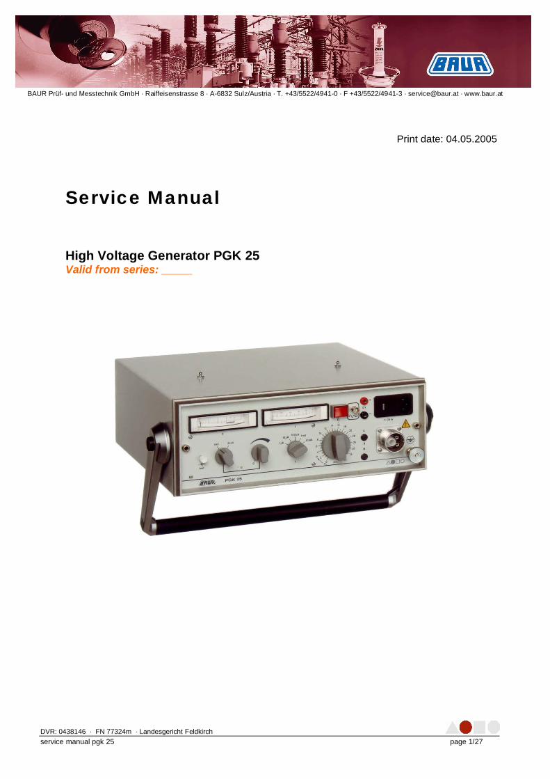
Service Manual High Voltage Generator PGK 25 Valid from series: _____
Print date: 04.05.2005
DVR: 0438146 · FN 77324m · Landesgericht Feldkirch
service manual pgk 25 page 2/27
Contents GENERAL INFORMATION 3 DATA SHEET OF PGK25 4
FEATURES: 4 TECHNICAL DATA PGK25 5
SYSTEM OVERVIEW 6
FUNDAMENTAL CLARIFICATIONS 6 FIRST STEPS TO FIND THE FAILURE 6 SERIAL NUMBER 6 LIST OF IMPORTANT DIAGRAMS 7
ERROR LIST 8 BASIC TESTS 10
FUNCTION TEST 10 FINDING OF THE FAILURE 10 CHECK THE POWER SUPPLY VOLTAGE: 10 EXECUTING TEST 10 SHORT – CIRCUIT TEST 10 NO-LOAD TEST 10
DISASSEMBLY OF THE DEVICE 11
PROTECTION AGAINST ELECTROSTATIC DISCHARGES 11 IDENTIFICATION OF IMPORTANT PARTS 12 DESCRIPTION OF SINGLE PLUG-IN CARDS 14 DESCRIPTION OF SINGLE PLUG-IN CARDS 15
PCB POWER, ID 461-838 15 PCB TRANSISTOR, ID 460-643 16 PCB CONTROL, ID 462-183 17
TROUBLE SHOOTING LIST 18 PERFORMANCE TEST PROCEDURE 23 EXAMPLE OF THE BAUR PERFORMANCE TEST REPORT 25 RECOMMEND SPARE PARTS 27
DVR: 0438146 · FN 77324m · Landesgericht Feldkirch
service manual pgk 25 page 3/27
General information Observe info signs!
• For fast finding of important information the
corresponding text passages are marked with symbols (symbols not stated here are self-explanatory).
• More and special information concerning the respective subject are available from BAUR.
• Important information about the instrument! • In any case, read carefully!
• Important information text.
© Copyright by BAUR
• © BAUR Prüf- und Messtechnik GmbH, 6832-Sulz • All rights reserved • No part of this publication may be reproduced,
transmitted, stored in a data processing system or translated into another language without the written permission of BAUR / Sulz, Austria.
Subject to modification!
• In the interest of our customers we reserve the
right for modifications due to technical progress. Illustrations, descriptions and delivery content are therefore not binding.
Subject to modification!
• This manual contains all information necessary for
the correct service of the system. Before you do it, please read carefully these manual.
• This document is for BAUR representatives only. • Observe all safety rules mentioned in the
operating manual of the systems. • Any non-authorized changes on hardware,
software or parameters may destroy the system and/or may be dangerous for the service technician or an user. Before implementing any changes, please contact BAUR Austria for more detailes.
• On any questions or problems contact BAUR After Sales Service in Austria
Tel: +43 / 5522 / 4941-0 Fax: +43 / 5522 / 4941 3 Email: [email protected]
DVR: 0438146 · FN 77324m · Landesgericht Feldkirch
service manual pgk 25 page 4/27
Data Sheet of PGK25 PGK 25 is a compact set for DC voltage testing with negative polarity up to 25 kV. Because of its different power supplies, this instrument can be used anywhere:
a) incorporated mains supply unit and charging unit 110 - 120 / 220 - 230 / 240 V; 50 - 60 Hz
b) incorporated battery 12 V c) external 12 V DC supply source possible
Features:
• integrated timer 1-30 min (± 1 min) with automatic final disconnection and release of discharge device
• stepless adjustable output voltage 0 - 5 kV and 0 - 25 kV DC
• voltage measurement is made directly at high voltage output
• zero interlock of high voltage
• high voltage plug with control contact
• current measurement: decade switching in 5 ranges
• plotter connection for current range 0 - 200 mV (for ungrounded input)
• connection for external battery, 12 V
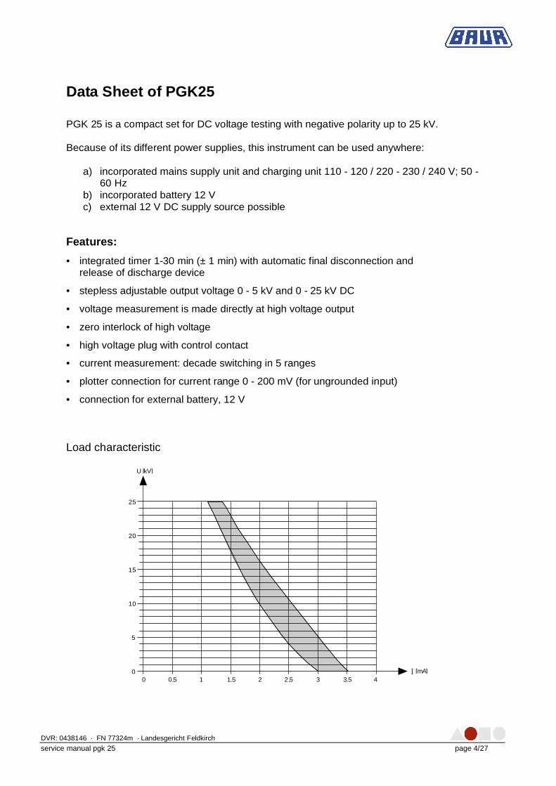
Load characteristic
0
5
10
15
20
25
0 0,5 1 1,5 2 2,5 3 3,5 4[mA]
U [kV]
I--
DVR: 0438146 · FN 77324m · Landesgericht Feldkirch
service manual pgk 25 page 5/27
Technical data PGK25 PGK 25 Connection energy 110 VA Output voltage 0 - 5 kV and 0 - 25 kV DC neg. Voltage measuring ranges analogue 5 / 25 kV Current delivery at nominal voltage 1 mA Short-circuit current 3 mA Current measuring ranges analogue 1 µA / 10 µA / 100 µA / 1 mA /
10 mA smallest reading current 50 nA Relative humidity not condensing Ambient temperature working: 0 ... + 45 ° C
storage: - 20 ... + 60 ° C Current supply (incorporated battery with charging unit)
12 V; 6,5 Ah
Operating time with battery at 2/3 load approx. 30 min Discharge energy: 10 min recovery time between 2 discharges 20 min recovery time between 2 discharges
max. 3000 Ws (9,6 µF / 25 kV) max. 5000 Ws (16 µF / 25 kV)
Dimensions (W x H x D) approx. 415 x 140 x 360 mm Weight approx. 16,5 kg
DVR: 0438146 · FN 77324m · Landesgericht Feldkirch
service manual pgk 25 page 6/27
System overview
Fundamental clarifications
a) Ask the customer after to a fault description Use for that purpose the official BAUR document “Complaint Report.doc”
First steps to find the failure
a) Make an optical check b) Switch on the faulty unit and check all functions c) If possible, check the output voltage d) If the failure (e.g. error code) occurs, see the below trouble shooting list and search
for possibilities to solving the problem e) If you need the actual circuit diagrams, send BAUR the claim description (include the
serial number)
Serial number
It is very important to know the serial number, only having this indication, we are able to collect circuit diagrams and drawings for investigation!
DVR: 0438146 · FN 77324m · Landesgericht Feldkirch
service manual pgk 25 page 7/27
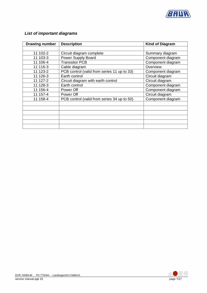
List of important diagrams
Drawing number Description Kind of Diagram
11 102-2 Circuit diagram complete Summary diagram 11 103-3 Power Supply Board Component diagram 11 106-4 Transsitor PCB Component diagram 11 116-3 Cable diagram Overview 11 123-2 PCB control (valid from series 11 up to 33) Component diagram 11 126-3 Earth control Circuit diagram 11 127-2 Circuit diagram with earth control Circuit diagram 11 128-3 Earth control Component diagram 11 156-4 Power Off Component diagram 11 157-4 Power Off Circuit diagram 11 158-4 PCB control (valid from series 34 up to 50) Component diagram
DVR: 0438146 · FN 77324m · Landesgericht Feldkirch
service manual pgk 25 page 8/27
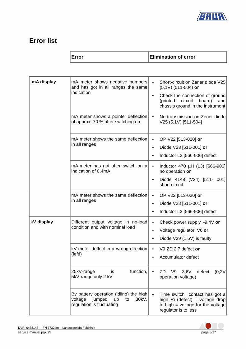
Error list
Error Elimination of error
mA display mA meter shows negative numbers and has got in all ranges the same indication
• Short-circuit on Zener diode V25 (5,1V) (511-504) or
• Check the connection of ground (printed circuit board) and chassis ground in the instrument
mA meter shows a pointer deflection of approx. 70 % after switching on
• No transmission on Zener diode V25 (5,1V) [511-504]
mA meter shows the same deflection in all ranges
• OP V22 [513-020] or
• Diode V23 [511-001] or
• Inductor L3 [566-906] defect
mA-meter has got after switch on a indication of 0,4mA
• Inductor 470 µH (L3) [566-906] no operation or
• Diode 4148 (V24) [511- 001] short circuit
mA meter shows the same deflection in all ranges
• OP V22 [513-020] or
• Diode V23 [511-001] or
• Inductor L3 [566-906] defect
kV display Different output voltage in no-load condition and with nominal load
• Check power supply -9,4V or
• Voltage regulator V6 or
• Diode V29 (1,5V) is faulty
kV-meter deflect in a wrong direction (left!)
• V9 ZD 2,7 defect or
• Accumulator defect
25kV-range is function, 5kV-range only 2 kV
• ZD V9 3,6V defect (0,2V operation voltage)
By battery operation (idling) the high voltage jumped up to 30kV, regulation is fluctuating
• Time switch contact has got a high Ri (defect) = voltage drop to high = voltage for the voltage regulator is to less
DVR: 0438146 · FN 77324m · Landesgericht Feldkirch
service manual pgk 25 page 9/27
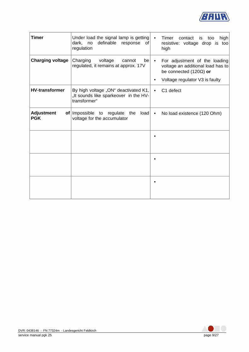
Timer Under load the signal lamp is getting dark, no definable response of regulation
• Timer contact is too high resistive: voltage drop is too high
Charging voltage Charging voltage cannot be regulated, it remains at approx. 17V
• For adjustment of the loading voltage an additional load has to be connected (120Ω) or
• Voltage regulator V3 is faulty
HV-transformer By high voltage „ON“ deactivated K1, „It sounds like sparkeover in the HV-transformer“
• C1 defect
Adjustment of PGK
Impossible to regulate the load voltage for the accumulator
• No load existence (120 Ohm)
•
•
•
DVR: 0438146 · FN 77324m · Landesgericht Feldkirch
service manual pgk 25 page 10/27
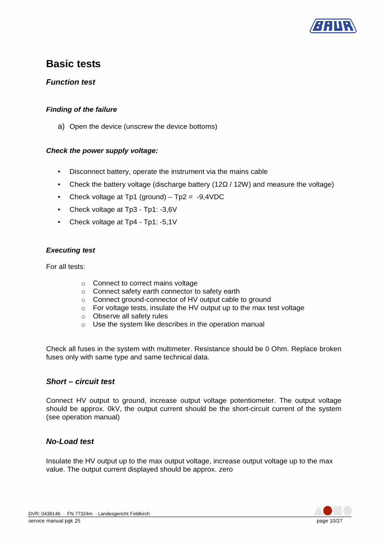
Basic tests
Function test
Finding of the failure
a) Open the device (unscrew the device bottoms)
Check the power supply voltage:
• Disconnect battery, operate the instrument via the mains cable
• Check the battery voltage (discharge battery (12Ω / 12W) and measure the voltage)
• Check voltage at Tp1 (ground) – Tp2 = -9,4VDC
• Check voltage at Tp3 - Tp1: -3,6V
• Check voltage at Tp4 - Tp1: -5,1V
Executing test For all tests:
o Connect to correct mains voltage o Connect safety earth connector to safety earth o Connect ground-connector of HV output cable to ground o For voltage tests, insulate the HV output up to the max test voltage o Observe all safety rules o Use the system like describes in the operation manual
Check all fuses in the system with multimeter. Resistance should be 0 Ohm. Replace broken fuses only with same type and same technical data.
Short – circuit test Connect HV output to ground, increase output voltage potentiometer. The output voltage should be approx. 0kV, the output current should be the short-circuit current of the system (see operation manual)
No-Load test
Insulate the HV output up to the max output voltage, increase output voltage up to the max value. The output current displayed should be approx. zero
DVR: 0438146 · FN 77324m · Landesgericht Feldkirch
service manual pgk 25 page 11/27
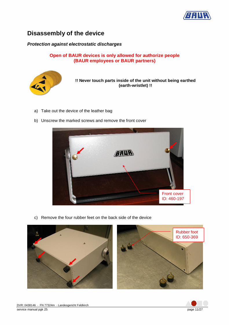
Disassembly of the device
Protection against electrostatic discharges
Open of BAUR devices is only allowed for authorize people (BAUR employees or BAUR partners)
!! Never touch parts inside of the unit without being earthed
(earth-wristlet) !!
a) Take out the device of the leather bag b) Unscrew the marked screws and remove the front cover
c) Remove the four rubber feet on the back side of the device
Front cover ID: 460-197
Rubber foot ID: 650-369
DVR: 0438146 · FN 77324m · Landesgericht Feldkirch
service manual pgk 25 page 12/27
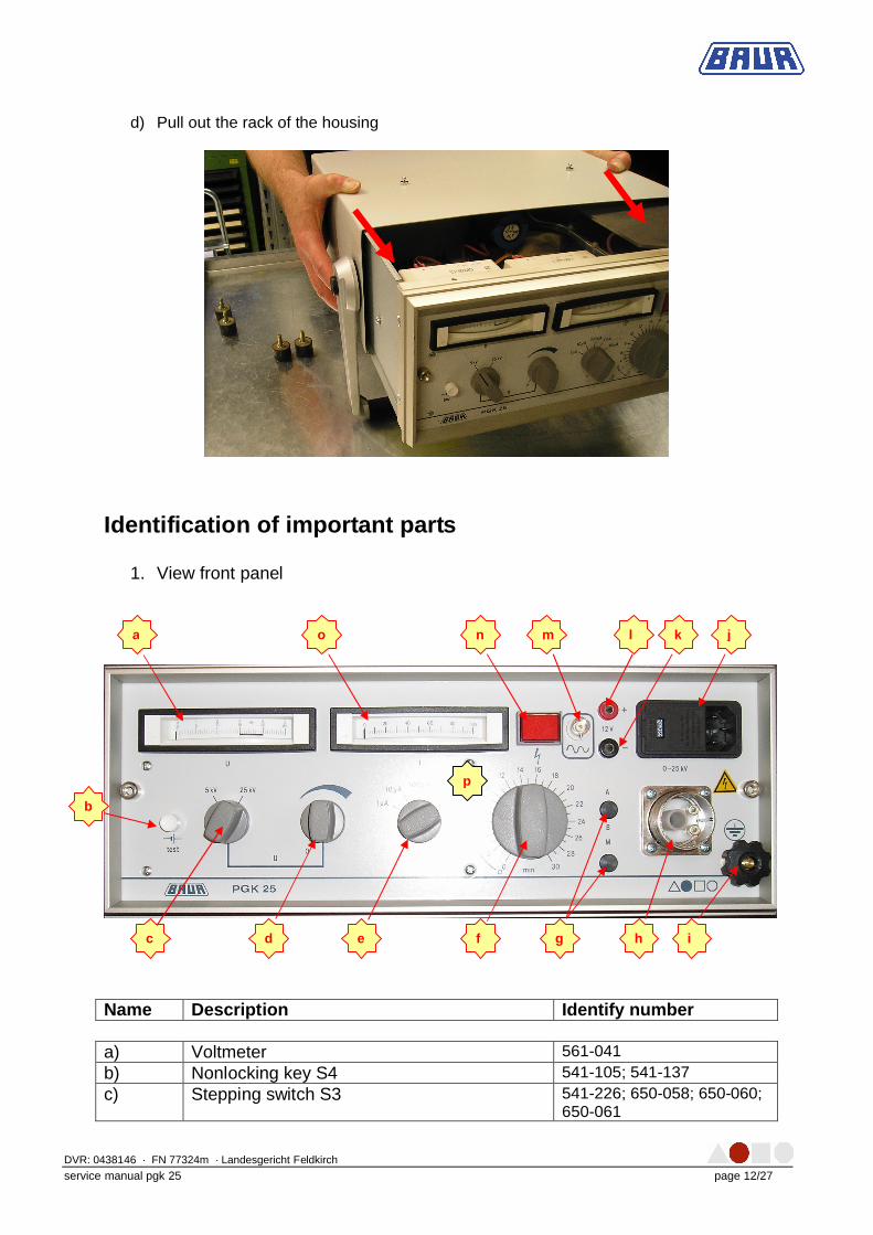
d) Pull out the rack of the housing
Identification of important parts
1. View front panel
Name Description Identify number
a) Voltmeter 561-041
b) Nonlocking key S4 541-105; 541-137
c) Stepping switch S3 541-226; 650-058; 650-060; 650-061
p
a
b
c d e f g h i
j l m
n o k
DVR: 0438146 · FN 77324m · Landesgericht Feldkirch
service manual pgk 25 page 13/27
Name Description Identify number
d) Potentiometer R8 with 2 switches 525-007; 650-058; 650-060; 650-061
e) Stepping switch S5 541-200; 650-059; 650-060; 650-061
f) Timer S1 440-849; 650-065; 650-066; 650-067
g) Fuses F1 and F2 563-069
h) HV socket 30kV 552-478
i) Earth connector 612-401; 440-052
j) Power input block 462-185
k) Banana socket black 552-306
l) Banana socket red 552-307
m) BNC socket 552-322
n) Indicator lamp H1 542-000; 541-160
o) Ammeter 561-042
p) Front panel 430-040
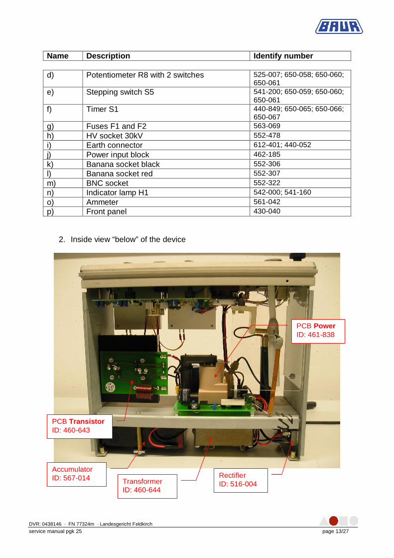
2. Inside view “below” of the device
PCB Power ID: 461-838
PCB Transistor ID: 460-643
Rectifier ID: 516-004
Accumulator ID: 567-014 Transformer
ID: 460-644
DVR: 0438146 · FN 77324m · Landesgericht Feldkirch
service manual pgk 25 page 14/27
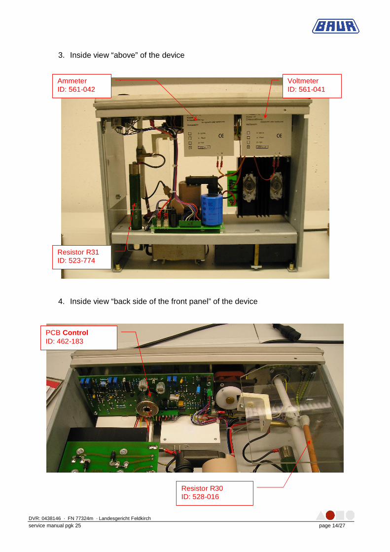
3. Inside view “above” of the device
4. Inside view “back side of the front panel” of the device
Ammeter ID: 561-042
Voltmeter ID: 561-041
Resistor R31 ID: 523-774
PCB Control ID: 462-183
Resistor R30 ID: 528-016
DVR: 0438146 · FN 77324m · Landesgericht Feldkirch
service manual pgk 25 page 15/27
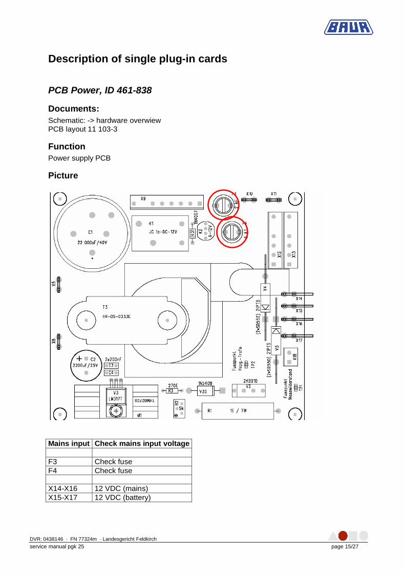
Description of single plug-in cards
PCB Power, ID 461-838
Documents: Schematic: -> hardware overwiew PCB layout 11 103-3
Function Power supply PCB
Picture
Mains input Check mains input voltage F3 Check fuse F4 Check fuse X14-X16 12 VDC (mains) X15-X17 12 VDC (battery)
DVR: 0438146 · FN 77324m · Landesgericht Feldkirch
service manual pgk 25 page 16/27
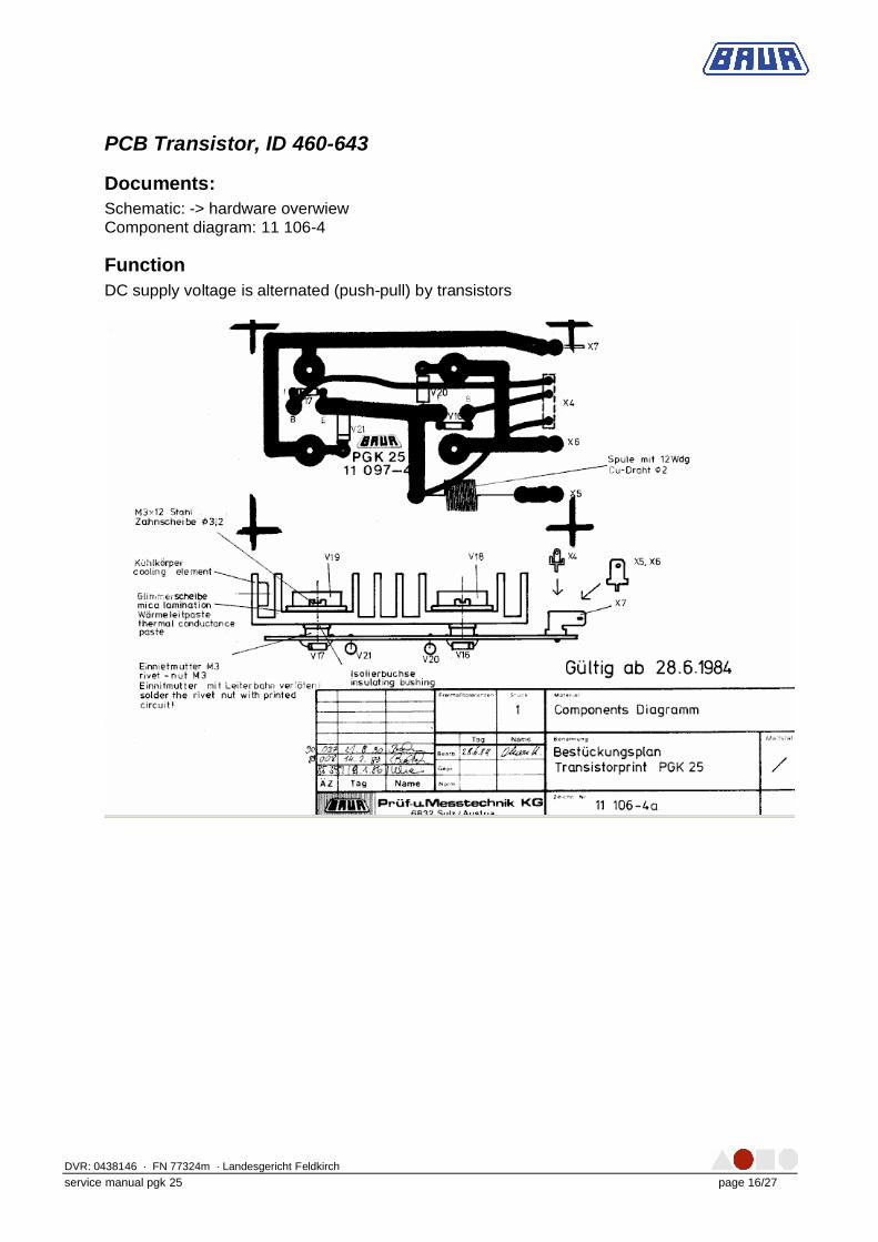
PCB Transistor, ID 460-643
Documents: Schematic: -> hardware overwiew Component diagram: 11 106-4
Function DC supply voltage is alternated (push-pull) by transistors
DVR: 0438146 · FN 77324m · Landesgericht Feldkirch
service manual pgk 25 page 17/27
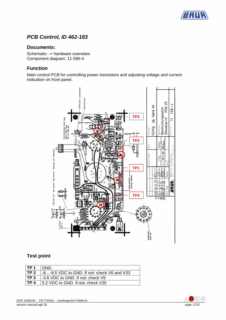
PCB Control, ID 462-183
Documents: Schematic: -> hardware overwiew Component diagram: 11 096-4
Function Main control PCB for controlling power transistors and adjusting voltage and current indication on front panel.
Test point TP 1 GND TP 2 -8… -9,5 VDC to GND. If not: check V6 and V33 TP 3 -3.6 VDC to GND. If not: check V9 TP 4 5.2 VDC to GND. If not: check V25
TP3
TP2
TP1
TP4
DVR: 0438146 · FN 77324m · Landesgericht Feldkirch
service manual pgk 25 page 18/27
Trouble shooting list
INSTRUCTION TO EXCHANGE TIMER-CONTACT 1. Unscrew the instrument hood 2. Loosen the 4 instrument feet ( ATTENTION: take care about the tooth lock washers) 3. Take the instrument out of the housing 4. Pinch off the plus-pole (red) from the battery
5. Loosen the hood of the control knob of the timer with knife: it is only sticked
6. Loosen the central fixing with a screw driver and take away the control knob from the
timer
7. Loosen both fixing screws of the timer at the front panel
8. Unsolder the two lines from the contacts of the timer
9. Mark the position of the switching-cam ( white plastic), that it can be built-in at the same position afterwards
10. Loosen both threaded bolts in the white switching-cam
11. Mark the timer and the hard-paper- hood, that that they can be assembled as before
afterwards
12. Unscrew the hard-paper-hood from the timer ( 2 screws), at the same time move the switching-cam to a position that the second screw appears
13. Strip away 8 downwards) the timer from the hard-paper-hood and the switching-cam
14. The timer contact can now be exchanged Please pay attention to the pressure-
spring!
15. Now the timer has to be sticked and screwed together ( from below) with the hard-paper-hood and the switching cam again
16. Fix the switching-cam at the correct position
17. Solder on the two lines again
18. Fix the timer with the 2 screws at the front panel
19. Mount the control knob
20. Check the position of the control knob by turning the same to the right hand side until
the stopper: the marketing of the control knob must show to 30.
DVR: 0438146 · FN 77324m · Landesgericht Feldkirch
service manual pgk 25 page 19/27
21. Checking of the discharge device: in idle-state (zero position) the HV- output must have contact with the discharge resistor
22. Stick the cap onto the control knob
23. Pinch on the plus-pole to the battery again
24. Slide the instrument into the housing and fix it with the instrument feet: Don’t forget
the tooth lock washers!
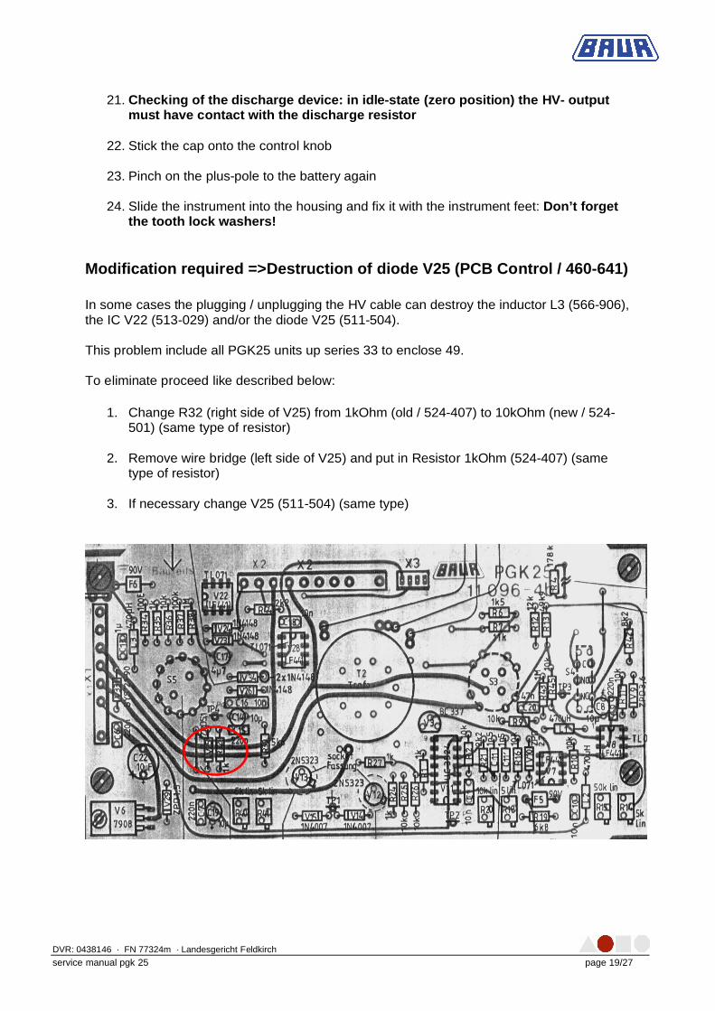
Modification required =>Destruction of diode V25 (PCB Control / 460-641) In some cases the plugging / unplugging the HV cable can destroy the inductor L3 (566-906), the IC V22 (513-029) and/or the diode V25 (511-504). This problem include all PGK25 units up series 33 to enclose 49. To eliminate proceed like described below:
1. Change R32 (right side of V25) from 1kOhm (old / 524-407) to 10kOhm (new / 524-501) (same type of resistor)
2. Remove wire bridge (left side of V25) and put in Resistor 1kOhm (524-407) (same
type of resistor)
3. If necessary change V25 (511-504) (same type)
DVR: 0438146 · FN 77324m · Landesgericht Feldkirch
service manual pgk 25 page 20/27
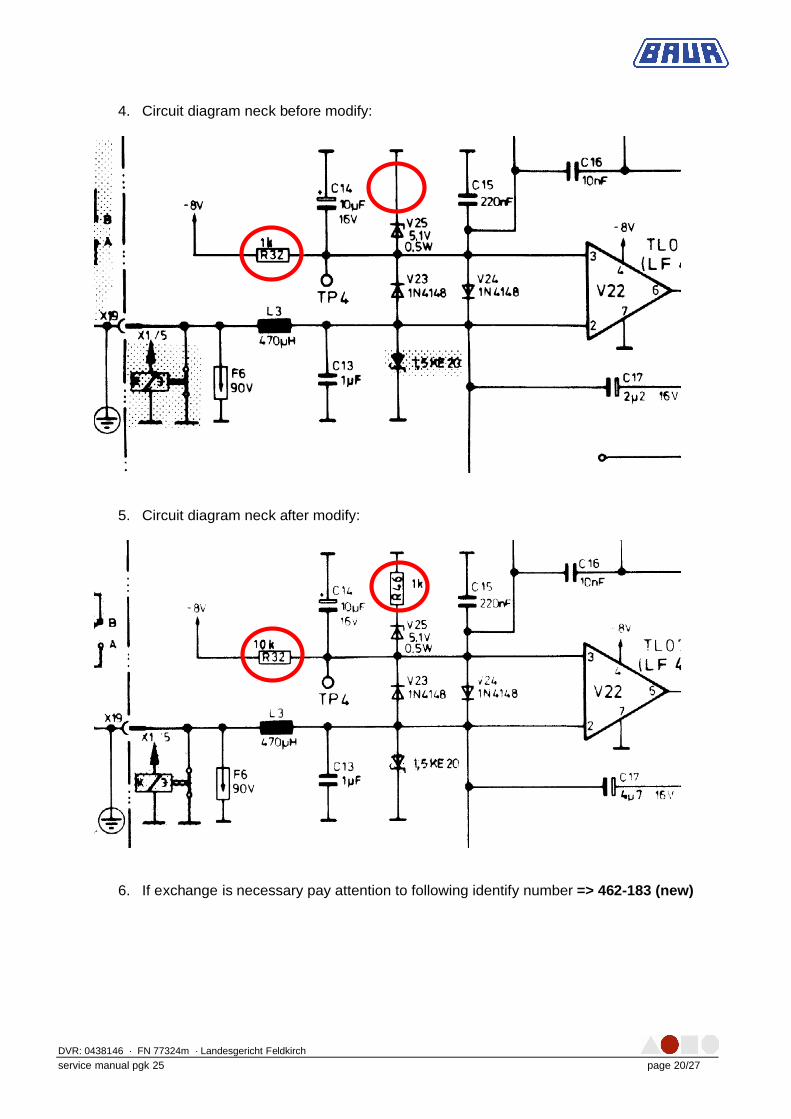
4. Circuit diagram neck before modify:
5. Circuit diagram neck after modify:
6. If exchange is necessary pay attention to following identify number => 462-183 (new)
DVR: 0438146 · FN 77324m · Landesgericht Feldkirch
service manual pgk 25 page 21/27
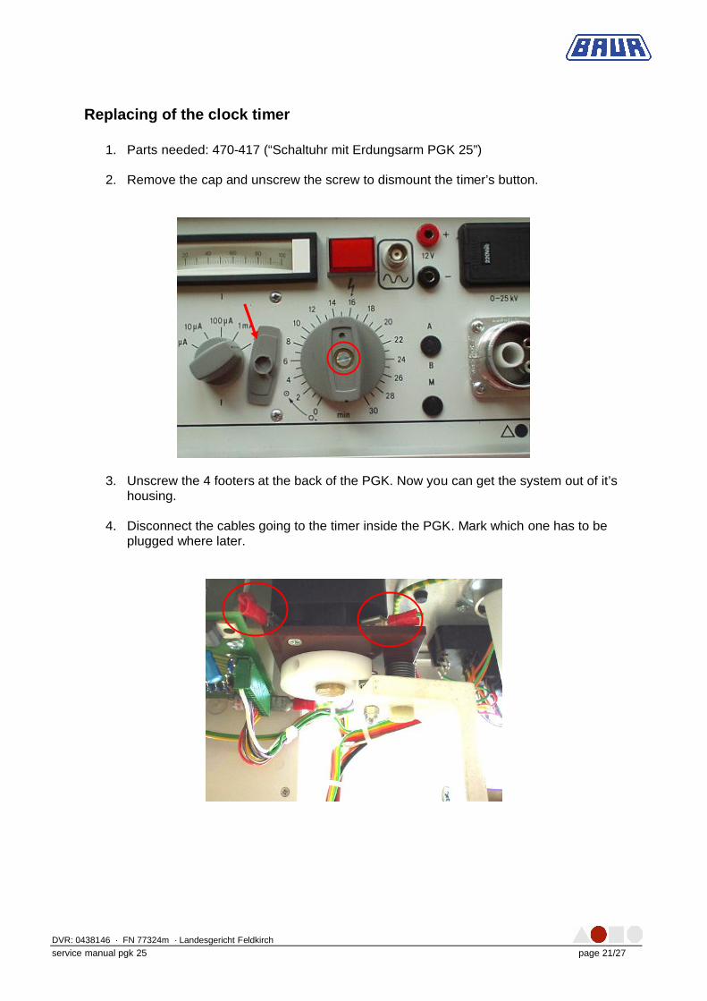
Replacing of the clock timer
1. Parts needed: 470-417 (“Schaltuhr mit Erdungsarm PGK 25”) 2. Remove the cap and unscrew the screw to dismount the timer’s button.
3. Unscrew the 4 footers at the back of the PGK. Now you can get the system out of it’s housing.
4. Disconnect the cables going to the timer inside the PGK. Mark which one has to be
plugged where later.
DVR: 0438146 · FN 77324m · Landesgericht Feldkirch
service manual pgk 25 page 22/27
5. Disassemble the cable going from the discharge part of the timer to the discharge resistor.
6. Dismount the clock timer from the front panel (4 screws on the front panel) and
exchange it. 7. Reassemble the unit in reverse order!
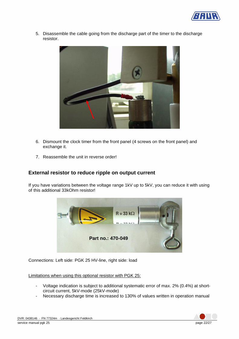
External resistor to reduce ripple on output current If you have variations between the voltage range 1kV up to 5kV, you can reduce it with using of this additional 33kOhm resistor!
Connections: Left side: PGK 25 HV-line, right side: load Limitations when using this optional resistor with PGK 25:
- Voltage indication is subject to additional systematic error of max. 2% (0.4%) at short-circuit current, 5kV-mode (25kV-mode)
- Necessary discharge time is increased to 130% of values written in operation manual
Part no.: 470-049
DVR: 0438146 · FN 77324m · Landesgericht Feldkirch
service manual pgk 25 page 23/27
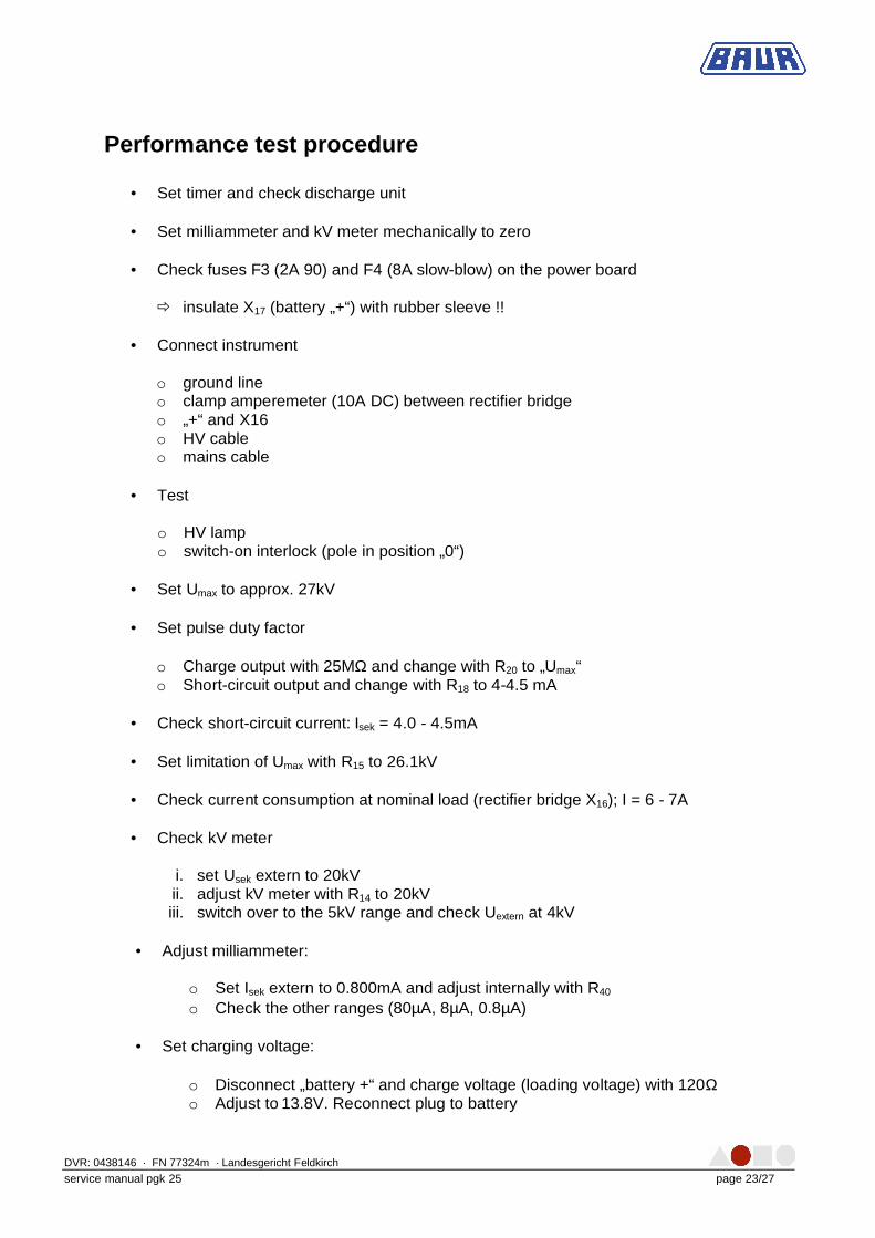
Performance test procedure
• Set timer and check discharge unit • Set milliammeter and kV meter mechanically to zero
• Check fuses F3 (2A 90) and F4 (8A slow-blow) on the power board
ð insulate X17 (battery „+“) with rubber sleeve !!
• Connect instrument
o ground line o clamp amperemeter (10A DC) between rectifier bridge o „+“ and X16 o HV cable o mains cable
• Test
o HV lamp o switch-on interlock (pole in position „0“)
• Set Umax to approx. 27kV • Set pulse duty factor
o Charge output with 25MΩ and change with R20 to „Umax“ o Short-circuit output and change with R18 to 4-4.5 mA
• Check short-circuit current: Isek = 4.0 - 4.5mA • Set limitation of Umax with R15 to 26.1kV
• Check current consumption at nominal load (rectifier bridge X16); I = 6 - 7A
• Check kV meter
i. set Usek extern to 20kV ii. adjust kV meter with R14 to 20kV iii. switch over to the 5kV range and check Uextern at 4kV
• Adjust milliammeter:
o Set Isek extern to 0.800mA and adjust internally with R40 o Check the other ranges (80µA, 8µA, 0.8µA)
• Set charging voltage:
o Disconnect „battery +“ and charge voltage (loading voltage) with 120Ω o Adjust to 13.8V. Reconnect plug to battery
DVR: 0438146 · FN 77324m · Landesgericht Feldkirch
service manual pgk 25 page 24/27
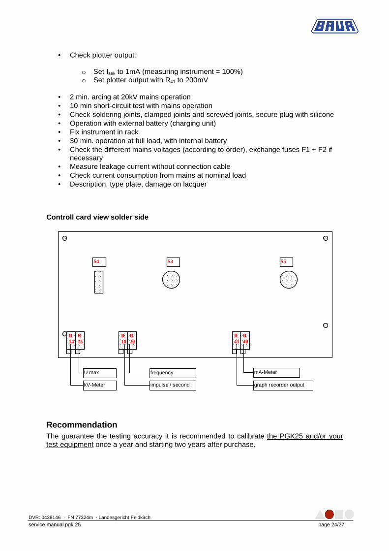
• Check plotter output:
o Set Isek to 1mA (measuring instrument = 100%) o Set plotter output with R41 to 200mV
• 2 min. arcing at 20kV mains operation • 10 min short-circuit test with mains operation • Check soldering joints, clamped joints and screwed joints, secure plug with silicone • Operation with external battery (charging unit) • Fix instrument in rack • 30 min. operation at full load, with internal battery • Check the different mains voltages (according to order), exchange fuses F1 + F2 if
necessary • Measure leakage current without connection cable • Check current consumption from mains at nominal load • Description, type plate, damage on lacquer
Controll card view solder side
Recommendation The guarantee the testing accuracy it is recommended to calibrate the PGK25 and/or your test equipment once a year and starting two years after purchase.
S5 S3 S4
R 40
R 41
R 20
R 18
R 15
R 14
mA-Meter
graph recorder output
frequency
impulse / second
U max
kV-Meter
DVR: 0438146 · FN 77324m · Landesgericht Feldkirch
service manual pgk 25 page 25/27
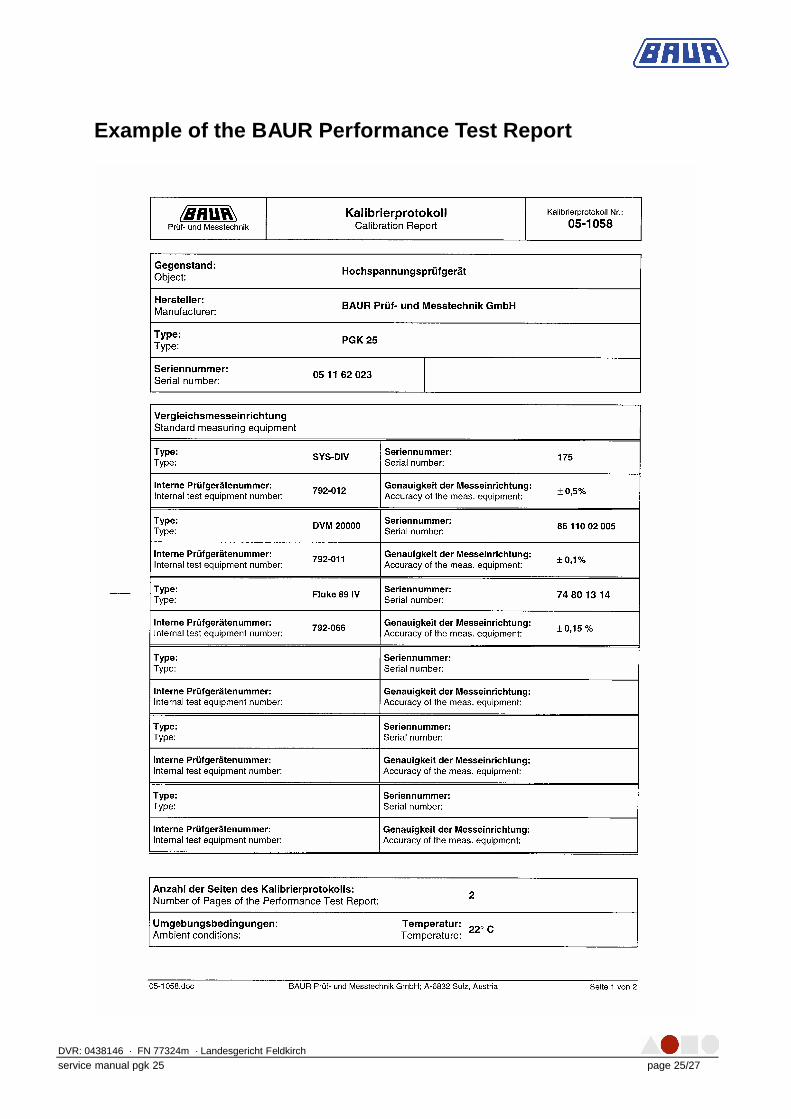
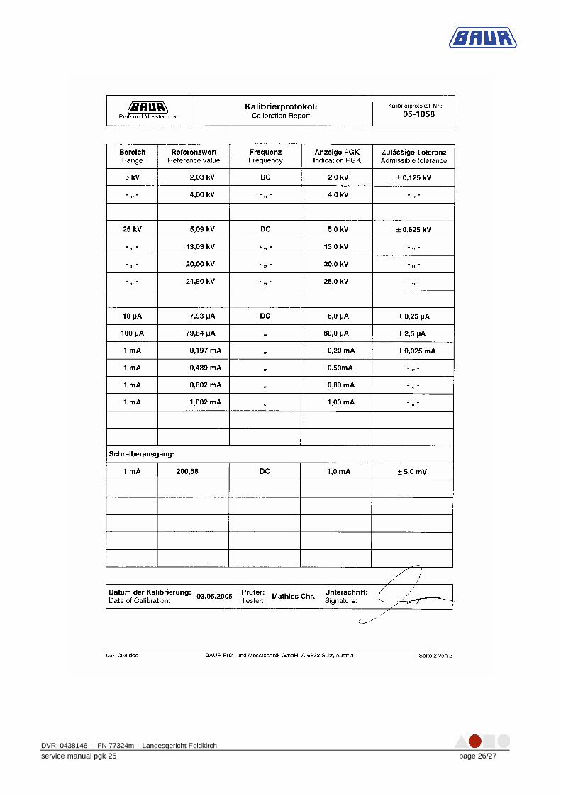
Example of the BAUR Performance Test Report
DVR: 0438146 · FN 77324m · Landesgericht Feldkirch
service manual pgk 25 page 26/27
DVR: 0438146 · FN 77324m · Landesgericht Feldkirch
service manual pgk 25 page 27/27
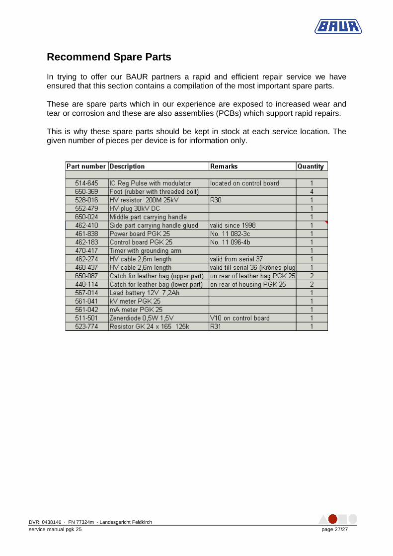
Recommend Spare Parts In trying to offer our BAUR partners a rapid and efficient repair service we have ensured that this section contains a compilation of the most important spare parts. These are spare parts which in our experience are exposed to increased wear and tear or corrosion and these are also assemblies (PCBs) which support rapid repairs. This is why these spare parts should be kept in stock at each service location. The given number of pieces per device is for information only.