Embed Size (px)
Citation preview
Service ManualTrucks
Group 41
Hydraulically Actuated Clutch(Including transmission removal)
VNL, VNM
PV776-TSP24581/1
Foreword
The descriptions and service procedures contained in this manual are based on designand method studies up to October 1996.
The products are under continuous development. Vehicles and components producedafter the above date may therefore have different specifications and repair methods.When this is believed to have a significant bearing on this manual, supplementary servicebulletins will be issued to cover the changes.
The new edition of this manual will update the changes.
In service procedures where the title incorporates an operation number, this is areference to an S.R.T. (Standard Repair Time).
Service procedures which do not include an operation number in the title are for generalinformation and no reference is made to an S.R.T.
The following levels of observations, cautions and warnings are used in this ServiceDocumentation:
Note: Indicates a procedure, practice, or condition that must be followed in order tohave the vehicle or component function in the manner intended.
Caution: Indicates an unsafe practice where damage to the product could occur.
Warning: Indicates an unsafe practice where personal injury or severe damage to theproduct could occur.
Danger: Indicates an unsafe practice where serious personal injury or death couldoccur.
Volvo GM Heavy TruckGreensboro, NC USA
Order number: PV776-TSP24581/1
© 1996 Volvo GM Heavy Truck, Greensboro, NC USA
All rights reserved. No part of this publication may be reproduced, stored inretrieval system, or transmitted in any forms by any means, electronic, me-chanical, photocopying, recording or otherwise, without the prior writtenpermission of Volvo GM Heavy Truck.
ContentsGeneral .................................................................................................... 3About this Service Information ................................................................ 3
Specifications ......................................................................................... 5Clutch ..................................................................................................... 5Clutch Master Cylinder .......................................................................... 5Transmission Slave Cylinder ................................................................. 6Hydraulic System ................................................................................... 7Tightening Torques ................................................................................ 7
Tools ....................................................................................................... 9Special tools .......................................................................................... 9Other equipment .................................................................................. 10
Design and Function ........................................................................... 11Clutch and Hydraulic Clutch System ..................................................... 11
Design .................................................................................................. 11Function ............................................................................................... 14
Service Procedures ............................................................................. 19Clutch removal ..................................................................................... 19Clutch plate changing and installation ................................................ 20Flywheel pilot bearing replacing .......................................................... 22Volvo clutch servo removal ................................................................. 23Volvo clutch servo installation ............................................................. 24Volvo clutch servo adjustment ............................................................ 24Master cylinder removal ...................................................................... 25Master cylinder installation .................................................................. 27Clutch slave cylinder removal ............................................................. 31Clutch slave cylinder installation ......................................................... 31Clutch bleeding procedure .................................................................. 33Upper clutch pedal adjustment ............................................................ 34Lower clutch pedal adjustment ............................................................ 34Micro-switch adjustment ...................................................................... 35Inhibitor valve splitter adjustment ........................................................ 36Transmission removal ......................................................................... 38
Volvo transmission ............................................................................ 38Non-Volvo transmission .................................................................... 42
Transmission installation ..................................................................... 44Volvo transmission ............................................................................ 44Non-Volvo transmission .................................................................... 48
Shift linkage removal ........................................................................... 50Shift linkage installation ....................................................................... 51
1

2
Group 41 Hydraulically Actuated Clutch About this Service Information
General
About this Service InformationThe information and instructions contained in this Service Information pertain to thefollowing components:
Clutch
• Volvo 17 single plate - model CL43S-O (previously KFD117E)
• Volvo 15 double plate - model CL38D-O (previously KFD215B)
• Spicer® Easy-PedalTM 1552 double plate, ceramic
Note: For more information on servicing the Volvo clutches, please refer to the VolvoService Manual 411–600, Clutch, Pull-Type — Volvo.
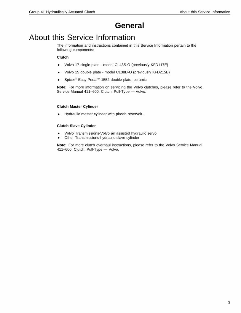
Clutch Master Cylinder
• Hydraulic master cylinder with plastic reservoir.
Clutch Slave Cylinder
• Volvo Transmissions-Volvo air assisted hydraulic servo• Other Transmissions-hydraulic slave cylinder
Note: For more clutch overhaul instructions, please refer to the Volvo Service Manual411–600, Clutch, Pull-Type — Volvo.
3

4
Group 41 Hydraulically Actuated Clutch Specifications
SpecificationsClutch
Volvo
Model Sizemm (in.)
Max. TorqueNm (lb•ft)
Spline Size Facing Material
CL43S-O (single plate) 430 (17) 1850 (1365) 10-SAE organic
CL38D-O (double plate) 380 (15) 1980 (1460) 10-SAE organic
Spicer
Model Sizemm (in.)
Max. TorqueNm (lb•ft)
Spline Size Facing Material
Easy-Pedal® PlusTM 1552(double plate)
394 (15.5) 1730 (1275)1970 (1450)2240 (1650)
10-SAE ceramic
Clutch Master Cylinder
P/N 1628218 (Volvo) or8076243 (Non-Volvo) ............................................................................................................................. Non-serviceable
5
Group 41 Hydraulically Actuated Clutch Specifications
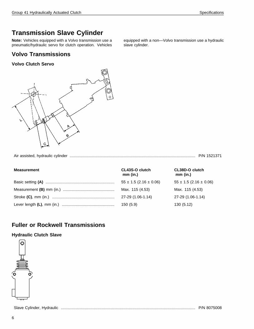
Transmission Slave CylinderNote: Vehicles equipped with a Volvo transmission use apneumatic/hydraulic servo for clutch operation. Vehicles
equipped with a non—Volvo transmission use a hydraulicslave cylinder.
Volvo Transmissions
Volvo Clutch Servo
Air assisted, hydraulic cylinder ................................................................................................................... P/N 1521371
Measurement CL43S-O clutchmm (in.)
CL38D-O clutchmm (in.)
Basic setting (A) ............................................................... 55 ± 1.5 (2.16 ± 0.06) 55 ± 1.5 (2.16 ± 0.06)
Measurement (B) mm (in.) ............................................... Max. 115 (4.53) Max. 115 (4.53)
Stroke (C), mm (in.) ......................................................... 27-29 (1.06-1.14) 27-29 (1.06-1.14)
Lever length (L), mm (in.) ................................................ 150 (5.9) 130 (5.12)
Fuller or Rockwell Transmissions
Hydraulic Clutch Slave
Slave Cylinder, Hydraulic ........................................................................................................................... P/N 8075008
6
Group 41 Hydraulically Actuated Clutch Specifications
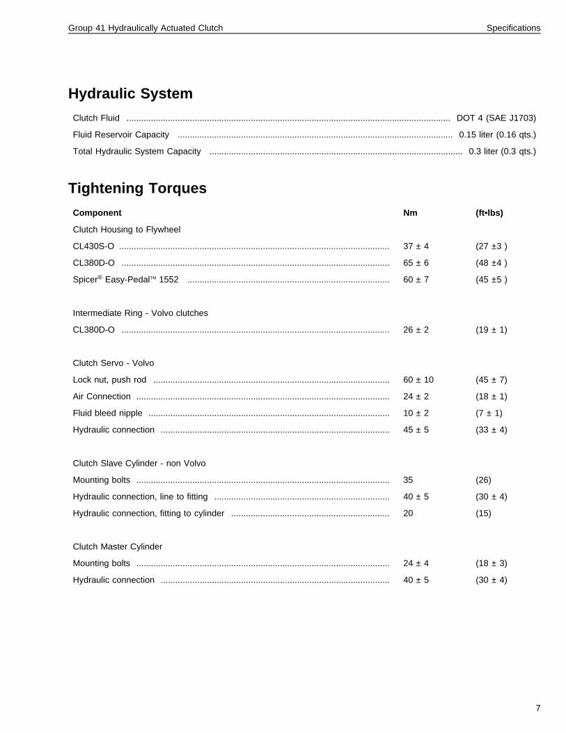
Hydraulic System
Clutch Fluid ..................................................................................................................................... DOT 4 (SAE J1703)
Fluid Reservoir Capacity ................................................................................................................. 0.15 liter (0.16 qts.)
Total Hydraulic System Capacity ........................................................................................................ 0.3 liter (0.3 qts.)
Tightening Torques
Component Nm (ft•lbs)
Clutch Housing to Flywheel
CL430S-O ............................................................................................................... 37 ± 4 (27 ±3 )
CL380D-O .............................................................................................................. 65 ± 6 (48 ±4 )
Spicer® Easy-PedalTM 1552 ................................................................................... 60 ± 7 (45 ±5 )
Intermediate Ring - Volvo clutches
CL380D-O .............................................................................................................. 26 ± 2 (19 ± 1)
Clutch Servo - Volvo
Lock nut, push rod ................................................................................................. 60 ± 10 (45 ± 7)
Air Connection ........................................................................................................ 24 ± 2 (18 ± 1)
Fluid bleed nipple ................................................................................................... 10 ± 2 (7 ± 1)
Hydraulic connection .............................................................................................. 45 ± 5 (33 ± 4)
Clutch Slave Cylinder - non Volvo
Mounting bolts ........................................................................................................ 35 (26)
Hydraulic connection, line to fitting ........................................................................ 40 ± 5 (30 ± 4)
Hydraulic connection, fitting to cylinder ................................................................. 20 (15)
Clutch Master Cylinder
Mounting bolts ........................................................................................................ 24 ± 4 (18 ± 3)
Hydraulic connection .............................................................................................. 40 ± 5 (30 ± 4)
7

8
Group 41 Hydraulically Actuated Clutch Tools
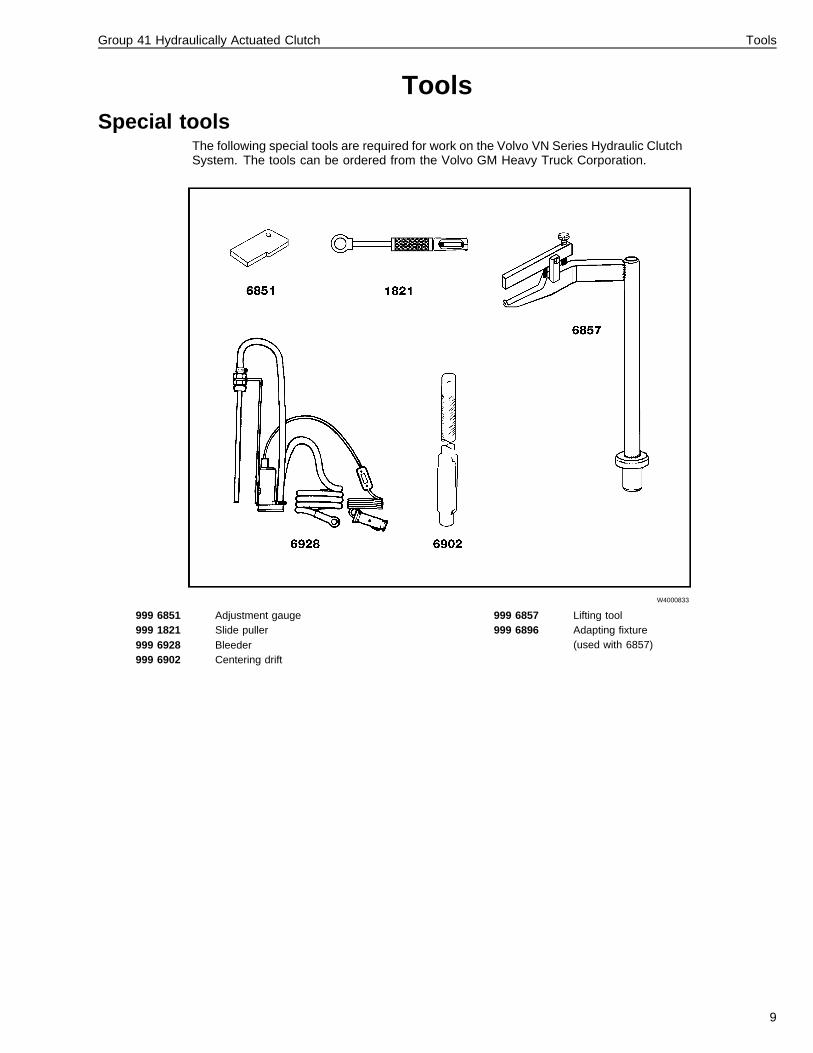
ToolsSpecial tools
The following special tools are required for work on the Volvo VN Series Hydraulic ClutchSystem. The tools can be ordered from the Volvo GM Heavy Truck Corporation.
W4000833
999 6851 Adjustment gauge999 1821 Slide puller999 6928 Bleeder999 6902 Centering drift
999 6857 Lifting tool999 6896 Adapting fixture
(used with 6857)
9
Group 41 Hydraulically Actuated Clutch Tools
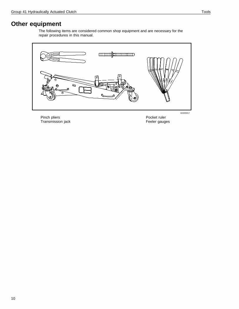
Other equipmentThe following items are considered common shop equipment and are necessary for therepair procedures in this manual.
W4000817
Pinch pliersTransmission jack
Pocket rulerFeeler gauges
10
Group 41 Hydraulically Actuated Clutch Clutch and Hydraulic Clutch System
Design and Function
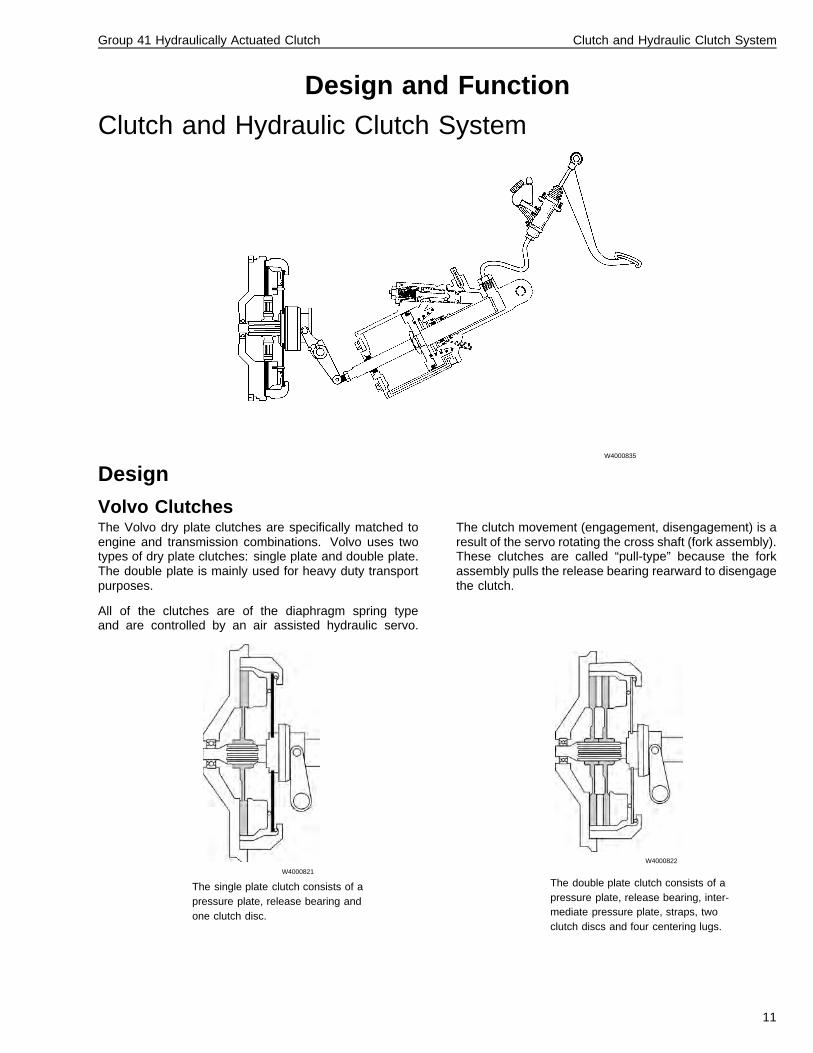
Clutch and Hydraulic Clutch System
W4000835
Design
Volvo ClutchesThe Volvo dry plate clutches are specifically matched toengine and transmission combinations. Volvo uses twotypes of dry plate clutches: single plate and double plate.The double plate is mainly used for heavy duty transportpurposes.
All of the clutches are of the diaphragm spring typeand are controlled by an air assisted hydraulic servo.
The clutch movement (engagement, disengagement) is aresult of the servo rotating the cross shaft (fork assembly).These clutches are called “pull-type” because the forkassembly pulls the release bearing rearward to disengagethe clutch.
W4000821
The single plate clutch consists of apressure plate, release bearing andone clutch disc.
W4000822
The double plate clutch consists of apressure plate, release bearing, inter-mediate pressure plate, straps, twoclutch discs and four centering lugs.
11
Group 41 Hydraulically Actuated Clutch Clutch and Hydraulic Clutch System
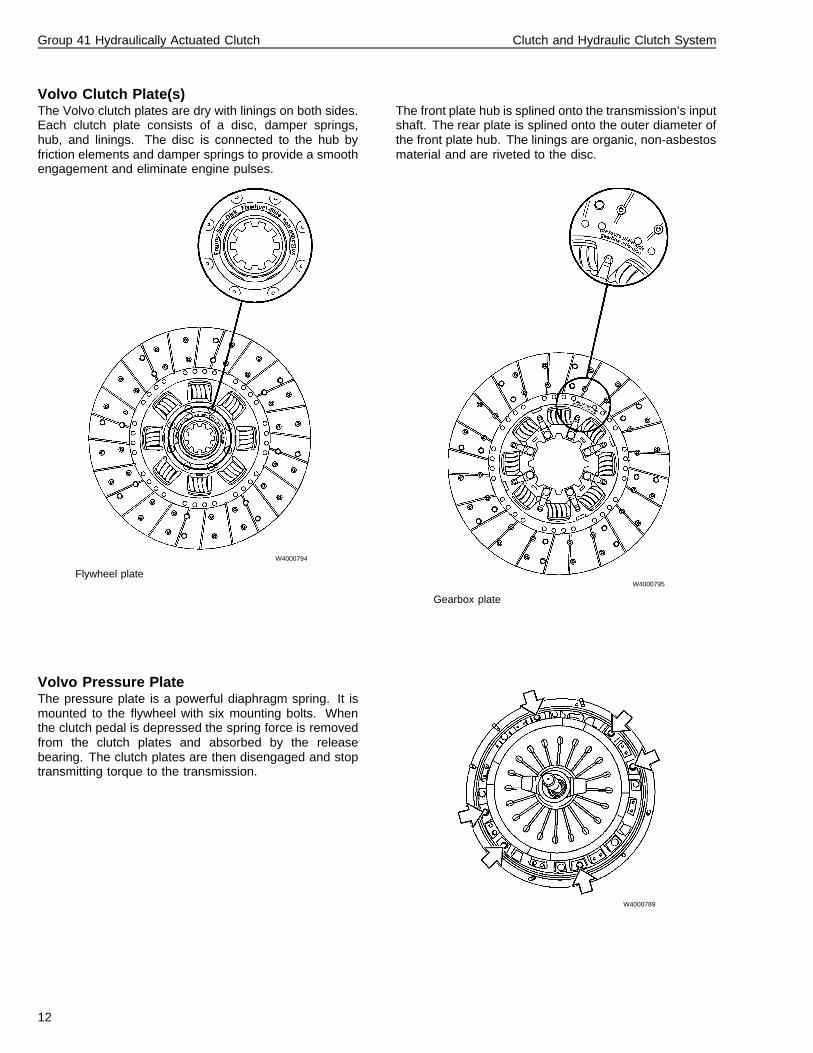
Volvo Clutch Plate(s)The Volvo clutch plates are dry with linings on both sides.Each clutch plate consists of a disc, damper springs,hub, and linings. The disc is connected to the hub byfriction elements and damper springs to provide a smoothengagement and eliminate engine pulses.
The front plate hub is splined onto the transmission’s inputshaft. The rear plate is splined onto the outer diameter ofthe front plate hub. The linings are organic, non-asbestosmaterial and are riveted to the disc.
W4000794
Flywheel plateW4000795
Gearbox plate
Volvo Pressure PlateThe pressure plate is a powerful diaphragm spring. It ismounted to the flywheel with six mounting bolts. Whenthe clutch pedal is depressed the spring force is removedfrom the clutch plates and absorbed by the releasebearing. The clutch plates are then disengaged and stoptransmitting torque to the transmission.
W4000789
12
Group 41 Hydraulically Actuated Clutch Clutch and Hydraulic Clutch System
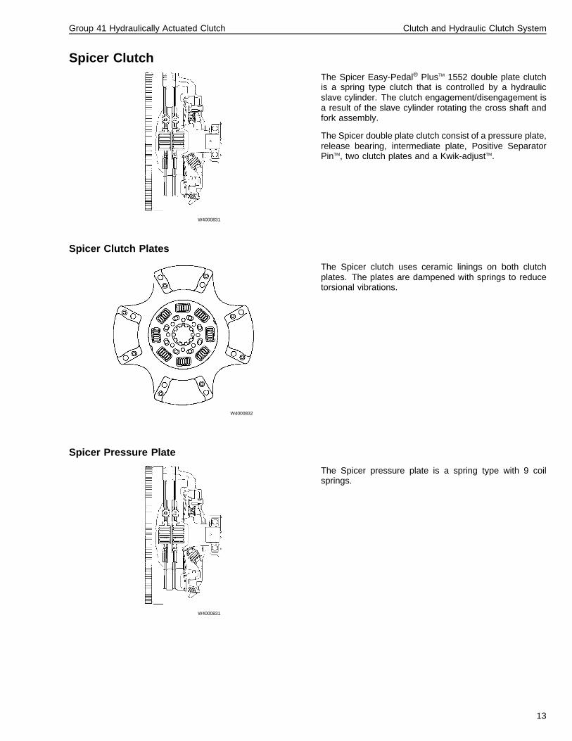
Spicer Clutch
W4000831
The Spicer Easy-Pedal® PlusTM 1552 double plate clutchis a spring type clutch that is controlled by a hydraulicslave cylinder. The clutch engagement/disengagement isa result of the slave cylinder rotating the cross shaft andfork assembly.
The Spicer double plate clutch consist of a pressure plate,release bearing, intermediate plate, Positive SeparatorPinTM, two clutch plates and a Kwik-adjustTM.
Spicer Clutch Plates
W4000832
The Spicer clutch uses ceramic linings on both clutchplates. The plates are dampened with springs to reducetorsional vibrations.
Spicer Pressure Plate
W4000831
The Spicer pressure plate is a spring type with 9 coilsprings.
13
Group 41 Hydraulically Actuated Clutch Clutch and Hydraulic Clutch System
Function
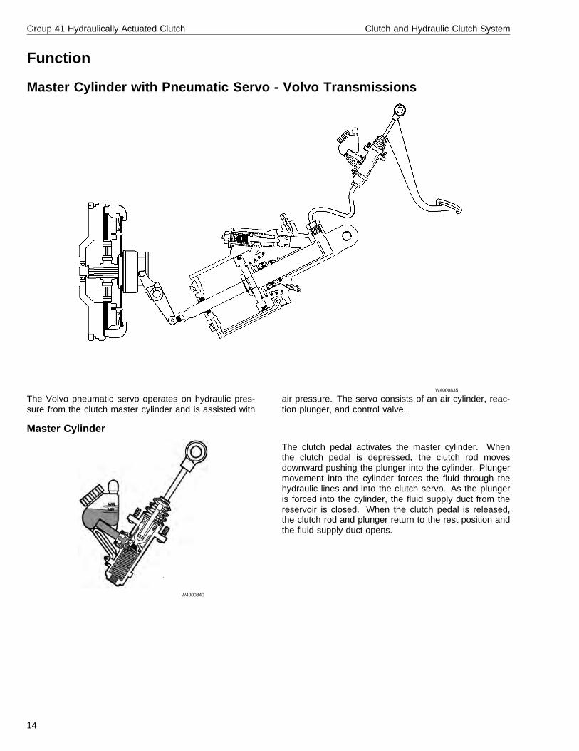
Master Cylinder with Pneumatic Servo - Volvo Transmissions
W4000835
The Volvo pneumatic servo operates on hydraulic pres-sure from the clutch master cylinder and is assisted with
air pressure. The servo consists of an air cylinder, reac-tion plunger, and control valve.
Master Cylinder
W4000840
The clutch pedal activates the master cylinder. Whenthe clutch pedal is depressed, the clutch rod movesdownward pushing the plunger into the cylinder. Plungermovement into the cylinder forces the fluid through thehydraulic lines and into the clutch servo. As the plungeris forced into the cylinder, the fluid supply duct from thereservoir is closed. When the clutch pedal is released,the clutch rod and plunger return to the rest position andthe fluid supply duct opens.
14
Group 41 Hydraulically Actuated Clutch Clutch and Hydraulic Clutch System
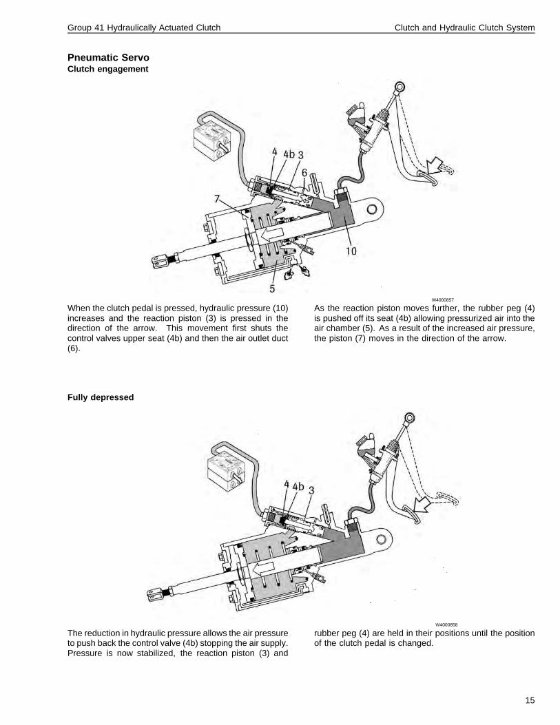
Pneumatic ServoClutch engagement
W4000857
When the clutch pedal is pressed, hydraulic pressure (10)increases and the reaction piston (3) is pressed in thedirection of the arrow. This movement first shuts thecontrol valves upper seat (4b) and then the air outlet duct(6).
As the reaction piston moves further, the rubber peg (4)is pushed off its seat (4b) allowing pressurized air into theair chamber (5). As a result of the increased air pressure,the piston (7) moves in the direction of the arrow.
Fully depressed
W4000858
The reduction in hydraulic pressure allows the air pressureto push back the control valve (4b) stopping the air supply.Pressure is now stabilized, the reaction piston (3) and
rubber peg (4) are held in their positions until the positionof the clutch pedal is changed.
15
Group 41 Hydraulically Actuated Clutch Clutch and Hydraulic Clutch System
Released
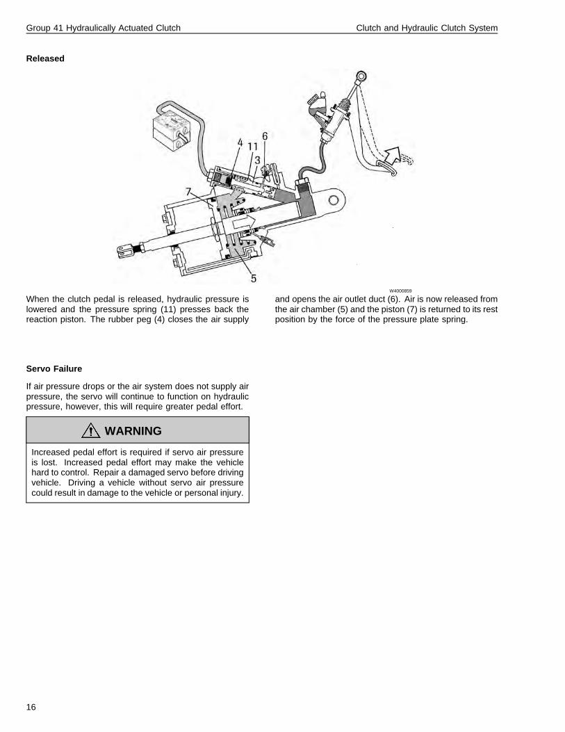
W4000859
When the clutch pedal is released, hydraulic pressure islowered and the pressure spring (11) presses back thereaction piston. The rubber peg (4) closes the air supply
and opens the air outlet duct (6). Air is now released fromthe air chamber (5) and the piston (7) is returned to its restposition by the force of the pressure plate spring.
Servo Failure
If air pressure drops or the air system does not supply airpressure, the servo will continue to function on hydraulicpressure, however, this will require greater pedal effort.
WARNING
Increased pedal effort is required if servo air pressureis lost. Increased pedal effort may make the vehiclehard to control. Repair a damaged servo before drivingvehicle. Driving a vehicle without servo air pressurecould result in damage to the vehicle or personal injury.
16
Group 41 Hydraulically Actuated Clutch Clutch and Hydraulic Clutch System
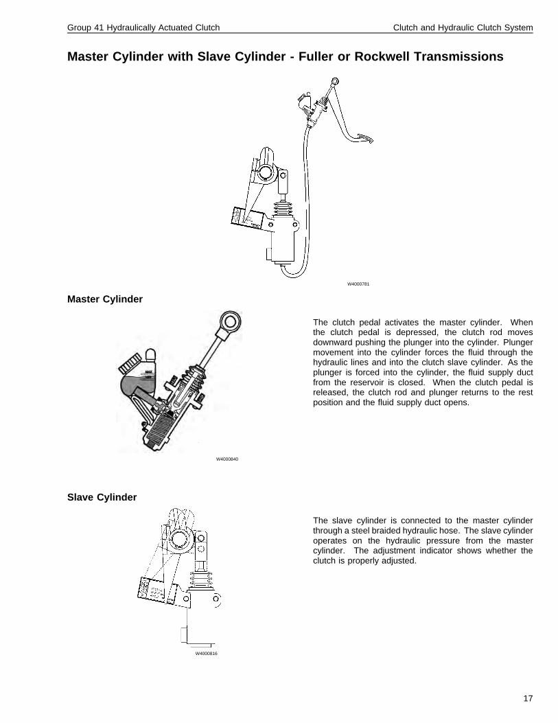
Master Cylinder with Slave Cylinder - Fuller or Rockwell Transmissions
W4000781
Master Cylinder
W4000840
The clutch pedal activates the master cylinder. Whenthe clutch pedal is depressed, the clutch rod movesdownward pushing the plunger into the cylinder. Plungermovement into the cylinder forces the fluid through thehydraulic lines and into the clutch slave cylinder. As theplunger is forced into the cylinder, the fluid supply ductfrom the reservoir is closed. When the clutch pedal isreleased, the clutch rod and plunger returns to the restposition and the fluid supply duct opens.
Slave Cylinder
W4000816
The slave cylinder is connected to the master cylinderthrough a steel braided hydraulic hose. The slave cylinderoperates on the hydraulic pressure from the mastercylinder. The adjustment indicator shows whether theclutch is properly adjusted.
17

18
Group 41 Hydraulically Actuated Clutch Service Procedures
Service Procedures
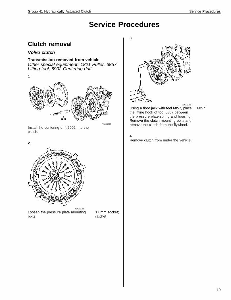
Clutch removalVolvo clutch
Transmission removed from vehicleOther special equipment: 1821 Puller, 6857Lifting tool, 6902 Centering drift
1
T4006506
Install the centering drift 6902 into theclutch.
2
W4000789
Loosen the pressure plate mountingbolts.
17 mm socket;ratchet
3
W4000790
Using a floor jack with tool 6857, placethe lifting hook of tool 6857 betweenthe pressure plate spring and housing.Remove the clutch mounting bolts andremove the clutch from the flywheel.
6857
4Remove clutch from under the vehicle.
19
Group 41 Hydraulically Actuated Clutch Service Procedures
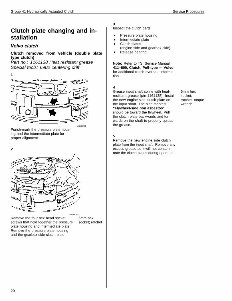
Clutch plate changing and in-stallationVolvo clutch
Clutch removed from vehicle (double platetype clutch)Part no.: 1161138 Heat resistant greaseSpecial tools: 6902 centering drift
1
W4000791
Punch-mark the pressure plate hous-ing and the intermediate plate forproper alignment.
2
W4000792
Remove the four hex head socketscrews that hold together the pressureplate housing and intermediate plate.Remove the pressure plate housingand the gearbox side clutch plate.
6mm hexsocket; ratchet
3Inspect the clutch parts:
• Pressure plate housing• Intermediate plate• Clutch plates
(engine side and gearbox side)• Release bearing
Note: Refer to TSI Service Manual411–600, Clutch, Pull-type — Volvofor additional clutch overhaul informa-tion.
4Grease input shaft spline with heat-resistant grease (p/n 1161138). Installthe new engine side clutch plate onthe input shaft. The side marked“Flywheel-side non asbestos”should be toward the flywheel. Pullthe clutch plate backwards and for-wards on the shaft to properly spreadthe grease.
6mm hexsocket;ratchet; torquewrench
5Remove the new engine side clutchplate from the input shaft. Remove anyexcess grease so it will not contami-nate the clutch plates during operation.
20
Group 41 Hydraulically Actuated Clutch Service Procedures
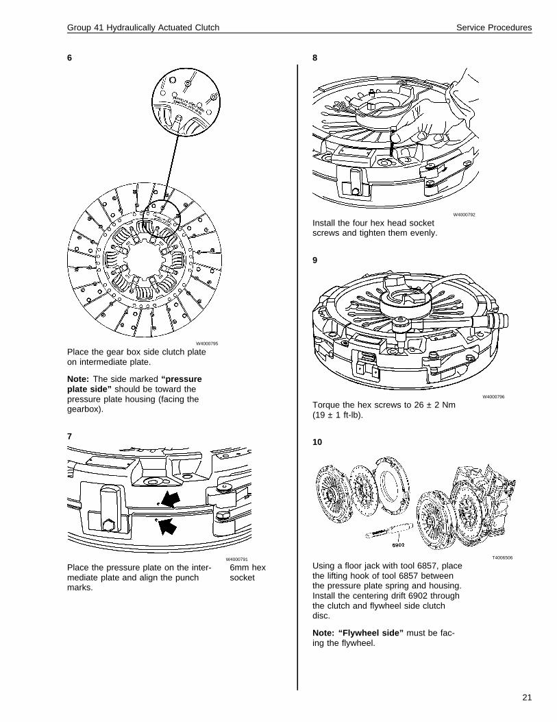
6
W4000795
Place the gear box side clutch plateon intermediate plate.
Note: The side marked “pressureplate side” should be toward thepressure plate housing (facing thegearbox).
7
W4000791
Place the pressure plate on the inter-mediate plate and align the punchmarks.
6mm hexsocket
8
W4000792
Install the four hex head socketscrews and tighten them evenly.
9
W4000796
Torque the hex screws to 26 ± 2 Nm(19 ± 1 ft-lb).
10
T4006506
Using a floor jack with tool 6857, placethe lifting hook of tool 6857 betweenthe pressure plate spring and housing.Install the centering drift 6902 throughthe clutch and flywheel side clutchdisc.
Note: “Flywheel side” must be fac-ing the flywheel.
21
Group 41 Hydraulically Actuated Clutch Service Procedures
11
W4000790
Install the clutch to the flywheel usingcentering drift 6902. Hand tighten boltsevenly to compress pressure plate.Torque the nuts to 85 Nm (63 ft-lb).
18 mm socket;torquewrench; 6857;6902
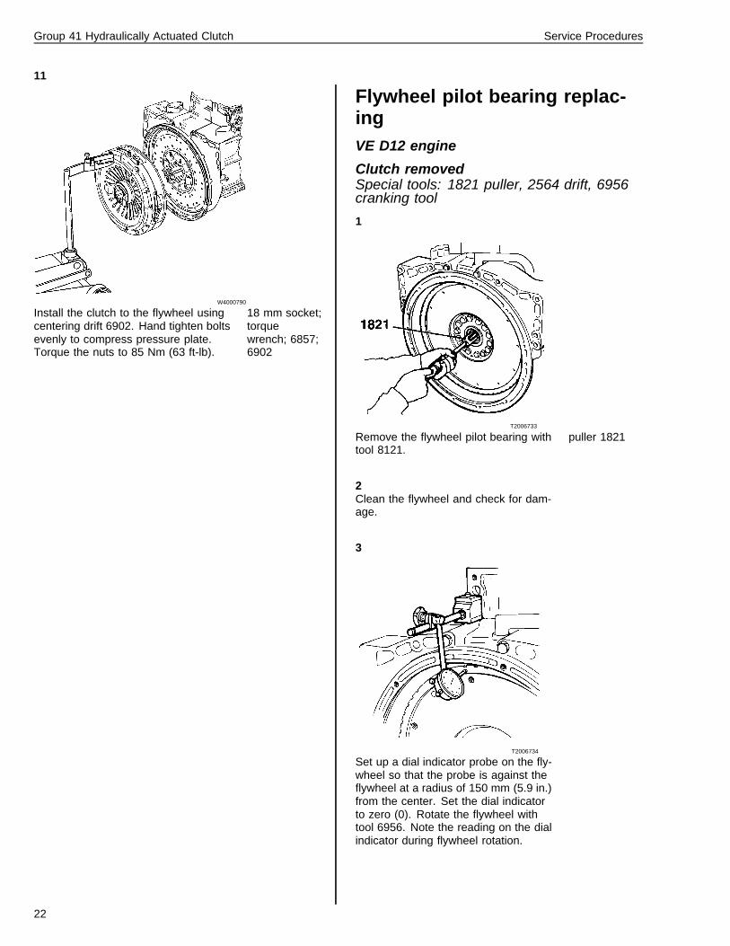
Flywheel pilot bearing replac-ingVE D12 engine
Clutch removedSpecial tools: 1821 puller, 2564 drift, 6956cranking tool
1
T2006733
Remove the flywheel pilot bearing withtool 8121.
puller 1821
2Clean the flywheel and check for dam-age.
3
T2006734
Set up a dial indicator probe on the fly-wheel so that the probe is against theflywheel at a radius of 150 mm (5.9 in.)from the center. Set the dial indicatorto zero (0). Rotate the flywheel withtool 6956. Note the reading on the dialindicator during flywheel rotation.
22
Group 41 Hydraulically Actuated Clutch Service Procedures
4If the dial indicator reading exceeded0.20 mm (0.0079 in.), remove the fly-wheel and inspect and clean thesurface between the flywheel and thecrankshaft.
Note: If the flywheel is out of specifi-cation after cleaning the crankshaftflange, the flywheel should be re-placed. Refer to TSI Service Manual210–600, Basic Engine, VE D12.
5
T2006732
Install the new flywheel pilot bearingusing drift 2564.
2564
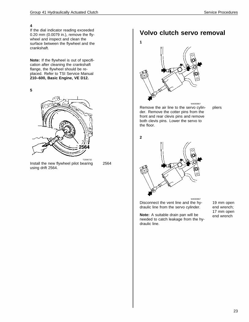
Volvo clutch servo removal1
W4000867
Remove the air line to the servo cylin-der. Remove the cotter pins from thefront and rear clevis pins and removeboth clevis pins. Lower the servo tothe floor.
pliers
2
W4000867
Disconnect the vent line and the hy-draulic line from the servo cylinder.
Note: A suitable drain pan will beneeded to catch leakage from the hy-draulic line.
19 mm openend wrench;17 mm openend wrench
23
Group 41 Hydraulically Actuated Clutch Service Procedures
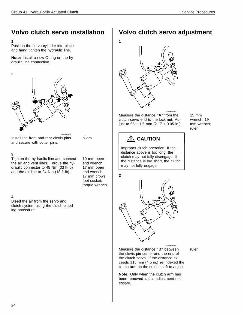
Volvo clutch servo installation1Position the servo cylinder into placeand hand tighten the hydraulic line.
Note: Install a new O-ring on the hy-draulic line connection.
2
W4000867
Install the front and rear clevis pinsand secure with cotter pins.
pliers
3Tighten the hydraulic line and connectthe air and vent lines. Torque the hy-draulic connector to 45 Nm (33 ft-lb)and the air line to 24 Nm (18 ft-lb).
19 mm openend wrench;17 mm openend wrench;17 mm crowsfoot socket;torque wrench
4Bleed the air from the servo andclutch system using the clutch bleed-ing procedure.
Volvo clutch servo adjustment1
W4000824
Measure the distance “A” from theclutch servo end to the lock nut. Ad-just to 55 ± 1.5 mm (2.17 ± 0.05 in.).
CAUTION
Improper clutch operation. If thedistance above is too long, theclutch may not fully disengage. Ifthe distance is too short, the clutchmay not fully engage.
15 mmwrench; 19mm wrench;ruler
2
W4000824
Measure the distance “B” betweenthe clevis pin center and the end ofthe clutch servo. If the distance ex-ceeds 115 mm (4.5 in.) re-indexed theclutch arm on the cross shaft to adjust.
Note: Only when the clutch arm hasbeen removed is this adjustment nec-essary.
ruler
24
Group 41 Hydraulically Actuated Clutch Service Procedures
3
W4000872
Pre-select splitter. Press the clutchpedal until just before the splitter shiftsand measure from the upper edge ofthe clutch pedal to the floor (E). Pressthe clutch pedal until it strikes thelower stop screw and re-measure fromthe upper edge of the clutch pedal tothe floor. The pedal movement fromsplitter to lower stop screw should be40 ± 5 mm (1.5 ± 13/64 in.).
ruler
4
W4000873
Measure the clutch servo stroke (D).Stroke should be 27–29 mm(1 9/16–1 9/64 in.).
ruler
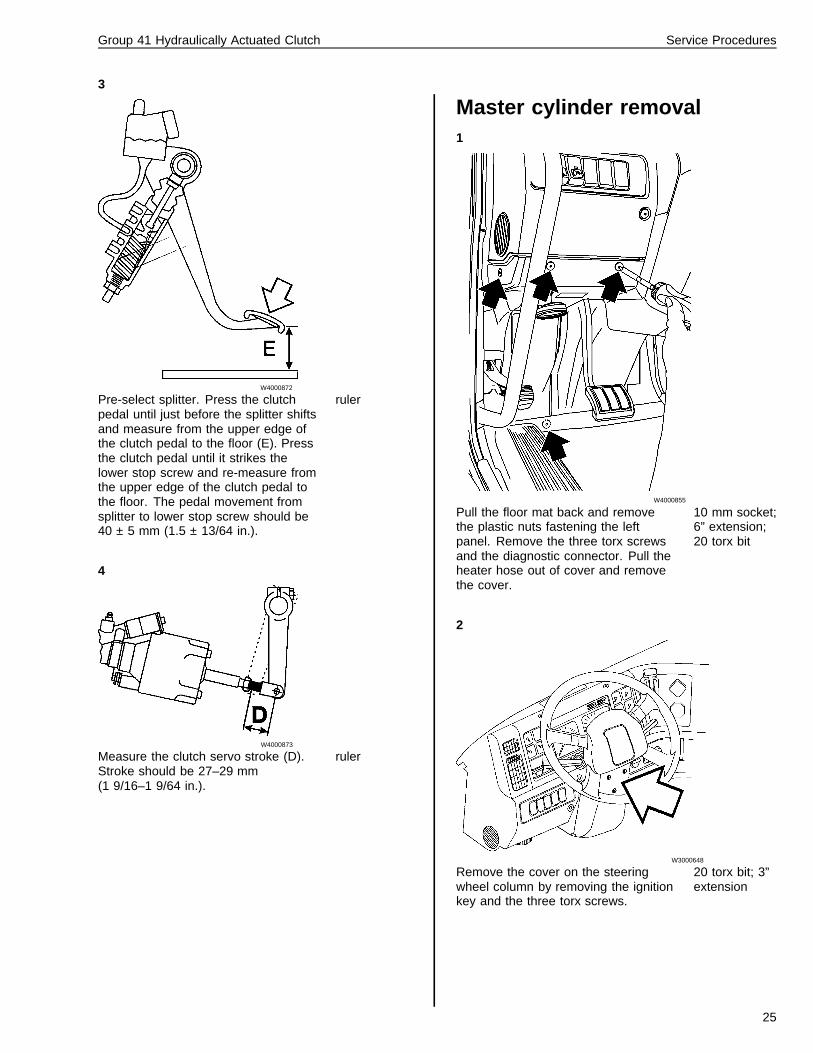
Master cylinder removal1
W4000855
Pull the floor mat back and removethe plastic nuts fastening the leftpanel. Remove the three torx screwsand the diagnostic connector. Pull theheater hose out of cover and removethe cover.
10 mm socket;6” extension;20 torx bit
2
W3000648
Remove the cover on the steeringwheel column by removing the ignitionkey and the three torx screws.
20 torx bit; 3”extension
25
Group 41 Hydraulically Actuated Clutch Service Procedures
3
W3000654
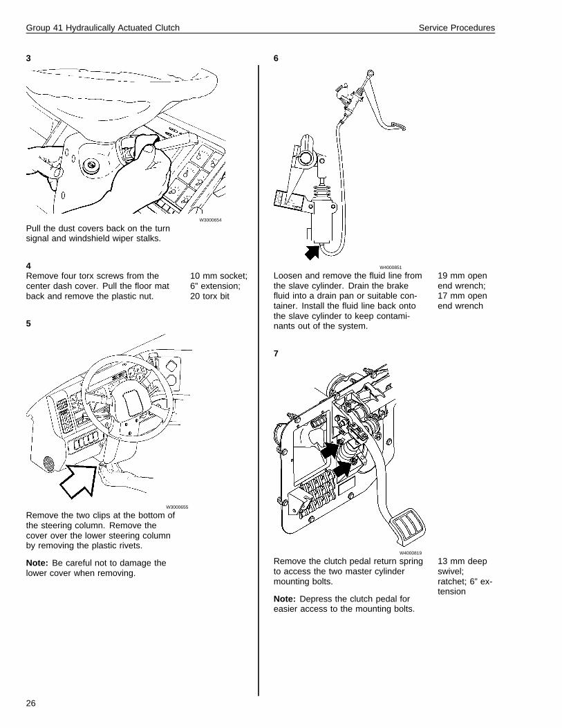
Pull the dust covers back on the turnsignal and windshield wiper stalks.
4Remove four torx screws from thecenter dash cover. Pull the floor matback and remove the plastic nut.
10 mm socket;6” extension;20 torx bit
5
W3000655
Remove the two clips at the bottom ofthe steering column. Remove thecover over the lower steering columnby removing the plastic rivets.
Note: Be careful not to damage thelower cover when removing.
6
W4000851
Loosen and remove the fluid line fromthe slave cylinder. Drain the brakefluid into a drain pan or suitable con-tainer. Install the fluid line back ontothe slave cylinder to keep contami-nants out of the system.
19 mm openend wrench;17 mm openend wrench
7
W4000819
Remove the clutch pedal return springto access the two master cylindermounting bolts.
Note: Depress the clutch pedal foreasier access to the mounting bolts.
13 mm deepswivel;ratchet; 6” ex-tension
26
Group 41 Hydraulically Actuated Clutch Service Procedures
8
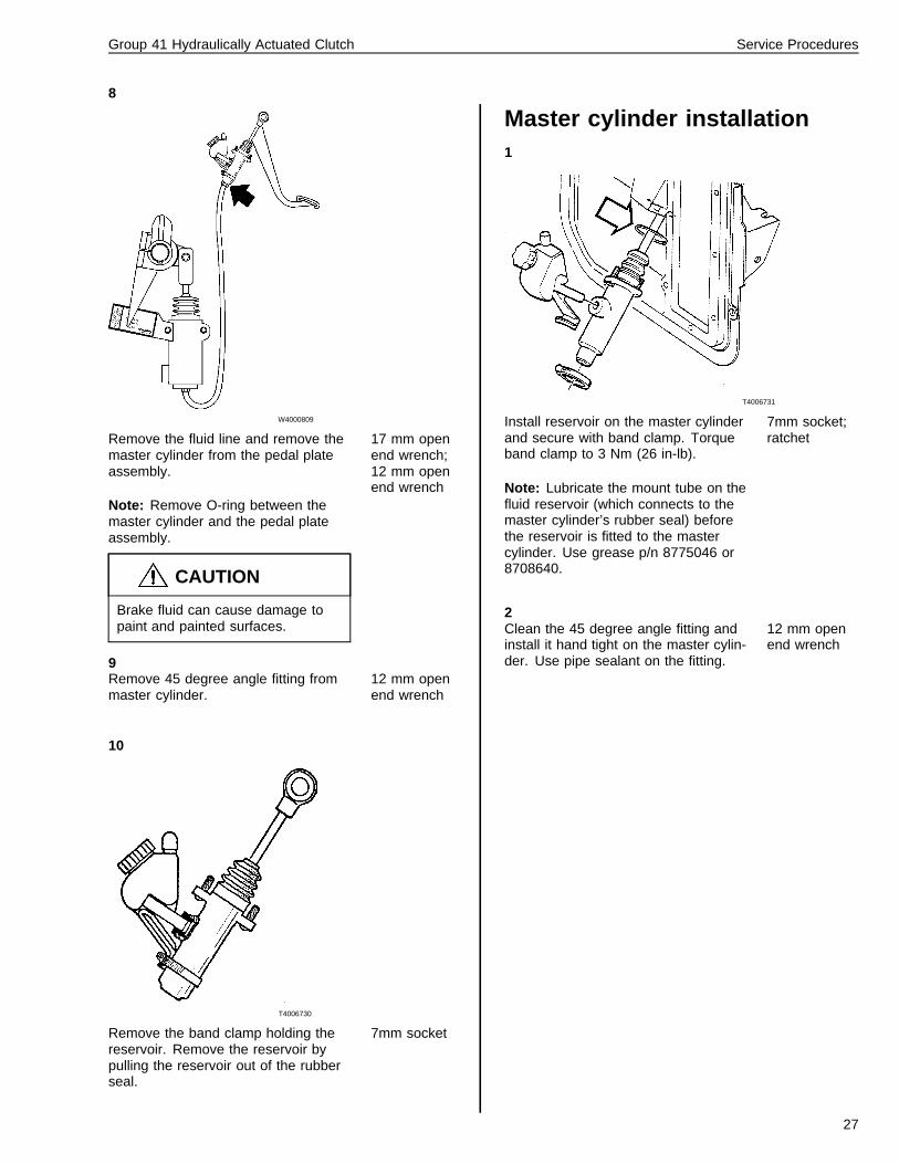
W4000809
Remove the fluid line and remove themaster cylinder from the pedal plateassembly.
Note: Remove O-ring between themaster cylinder and the pedal plateassembly.
CAUTION
Brake fluid can cause damage topaint and painted surfaces.
17 mm openend wrench;12 mm openend wrench
9Remove 45 degree angle fitting frommaster cylinder.
12 mm openend wrench
10
T4006730
Remove the band clamp holding thereservoir. Remove the reservoir bypulling the reservoir out of the rubberseal.
7mm socket
Master cylinder installation1
T4006731
Install reservoir on the master cylinderand secure with band clamp. Torqueband clamp to 3 Nm (26 in-lb).
Note: Lubricate the mount tube on thefluid reservoir (which connects to themaster cylinder’s rubber seal) beforethe reservoir is fitted to the mastercylinder. Use grease p/n 8775046 or8708640.
7mm socket;ratchet
2Clean the 45 degree angle fitting andinstall it hand tight on the master cylin-der. Use pipe sealant on the fitting.
12 mm openend wrench
27
Group 41 Hydraulically Actuated Clutch Service Procedures
3
W4000819
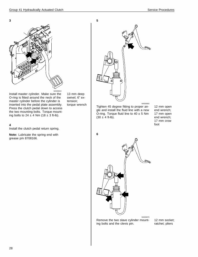
Install master cylinder. Make sure theO-ring is fitted around the neck of themaster cylinder before the cylinder isinserted into the pedal plate assembly.Press the clutch pedal down to accessthe two mounting bolts. Torque mount-ing bolts to 24 ± 4 Nm (18 ± 3 ft-lb).
13 mm deepswivel; 6” ex-tension;torque wrench
4Install the clutch pedal return spring.
Note: Lubricate the spring end withgrease p/n 8708166.
5
W4000850
Tighten 45 degree fitting to proper an-gle and install the fluid line with a newO-ring. Torque fluid line to 40 ± 5 Nm(30 ± 4 ft-lb).
12 mm openend wrench;17 mm openend wrench;17 mm crowfoot
6
W4000870
Remove the two slave cylinder mount-ing bolts and the clevis pin.
12 mm socket;ratchet; pliers
28
Group 41 Hydraulically Actuated Clutch Service Procedures
7
W4000810
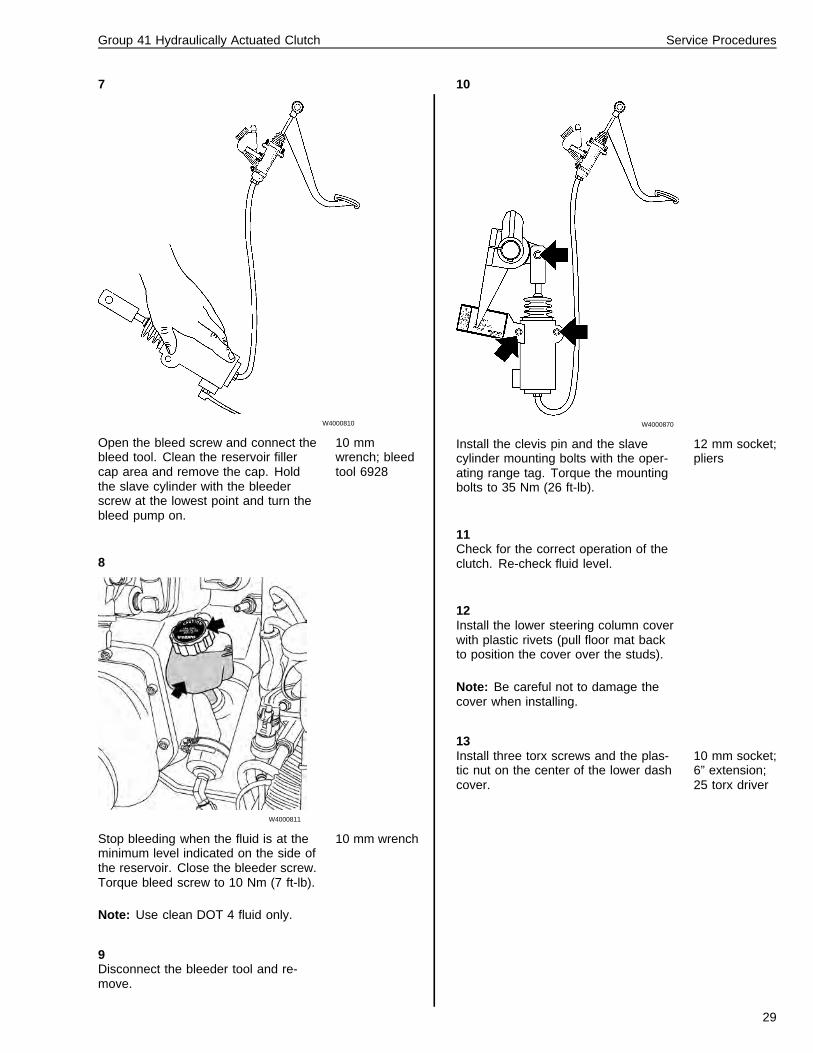
Open the bleed screw and connect thebleed tool. Clean the reservoir fillercap area and remove the cap. Holdthe slave cylinder with the bleederscrew at the lowest point and turn thebleed pump on.
10 mmwrench; bleedtool 6928
8
W4000811
Stop bleeding when the fluid is at theminimum level indicated on the side ofthe reservoir. Close the bleeder screw.Torque bleed screw to 10 Nm (7 ft-lb).
Note: Use clean DOT 4 fluid only.
10 mm wrench
9Disconnect the bleeder tool and re-move.
10
W4000870
Install the clevis pin and the slavecylinder mounting bolts with the oper-ating range tag. Torque the mountingbolts to 35 Nm (26 ft-lb).
12 mm socket;pliers
11Check for the correct operation of theclutch. Re-check fluid level.
12Install the lower steering column coverwith plastic rivets (pull floor mat backto position the cover over the studs).
Note: Be careful not to damage thecover when installing.
13Install three torx screws and the plas-tic nut on the center of the lower dashcover.
10 mm socket;6” extension;25 torx driver
29
Group 41 Hydraulically Actuated Clutch Service Procedures
14
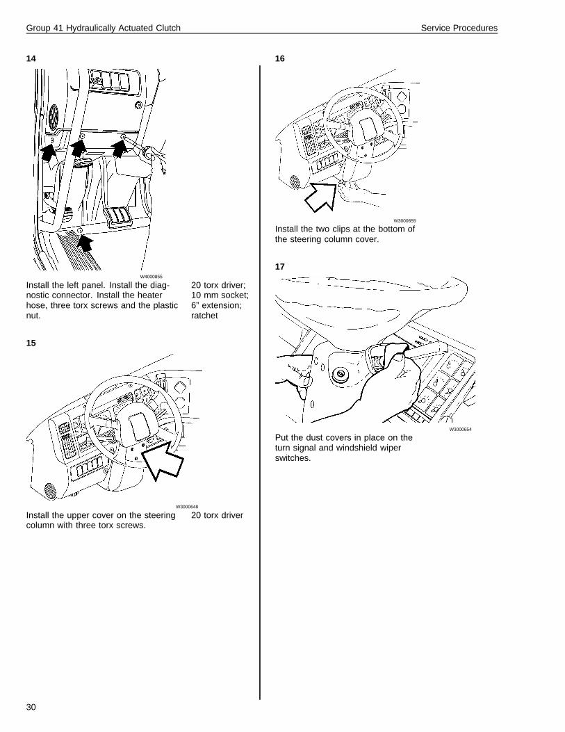
W4000855
Install the left panel. Install the diag-nostic connector. Install the heaterhose, three torx screws and the plasticnut.
20 torx driver;10 mm socket;6” extension;ratchet
15
W3000648
Install the upper cover on the steeringcolumn with three torx screws.
20 torx driver
16
W3000655
Install the two clips at the bottom ofthe steering column cover.
17
W3000654
Put the dust covers in place on theturn signal and windshield wiperswitches.
30
Group 41 Hydraulically Actuated Clutch Service Procedures
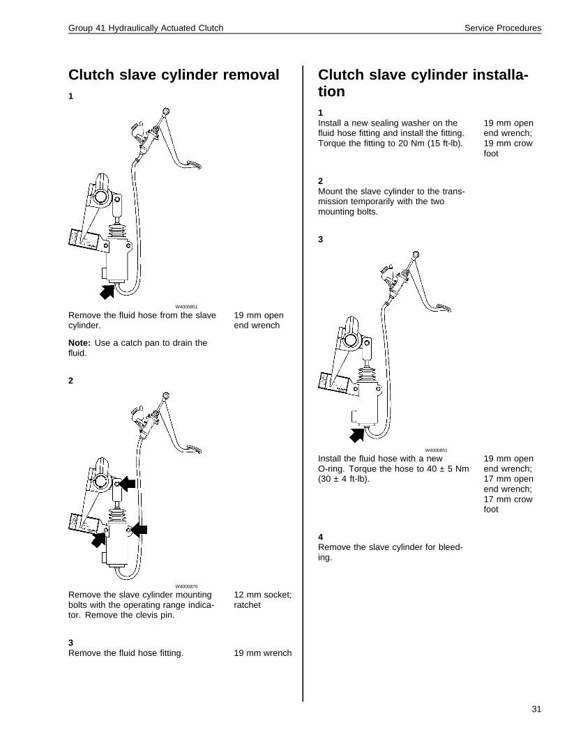
Clutch slave cylinder removal1
W4000851
Remove the fluid hose from the slavecylinder.
Note: Use a catch pan to drain thefluid.
19 mm openend wrench
2
W4000870
Remove the slave cylinder mountingbolts with the operating range indica-tor. Remove the clevis pin.
12 mm socket;ratchet
3Remove the fluid hose fitting. 19 mm wrench
Clutch slave cylinder installa-tion1Install a new sealing washer on thefluid hose fitting and install the fitting.Torque the fitting to 20 Nm (15 ft-lb).
19 mm openend wrench;19 mm crowfoot
2Mount the slave cylinder to the trans-mission temporarily with the twomounting bolts.
3
W4000851
Install the fluid hose with a newO-ring. Torque the hose to 40 ± 5 Nm(30 ± 4 ft-lb).
19 mm openend wrench;17 mm openend wrench;17 mm crowfoot
4Remove the slave cylinder for bleed-ing.
31
Group 41 Hydraulically Actuated Clutch Service Procedures
5
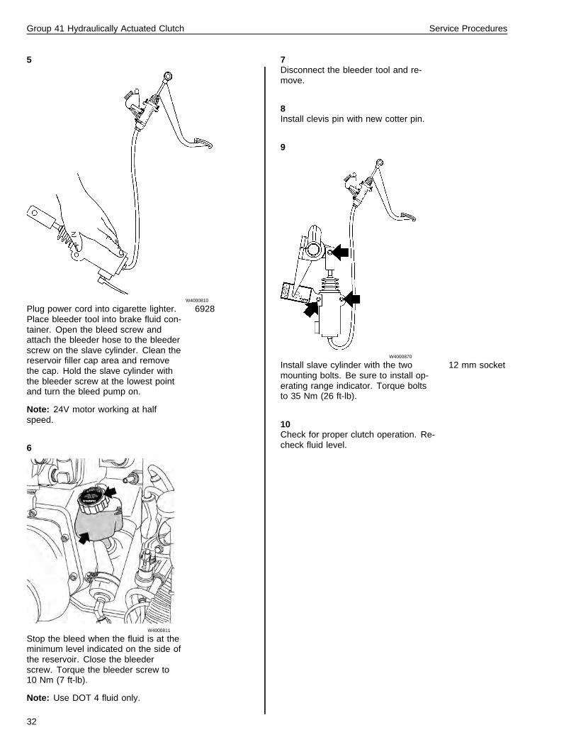
W4000810
Plug power cord into cigarette lighter.Place bleeder tool into brake fluid con-tainer. Open the bleed screw andattach the bleeder hose to the bleederscrew on the slave cylinder. Clean thereservoir filler cap area and removethe cap. Hold the slave cylinder withthe bleeder screw at the lowest pointand turn the bleed pump on.
Note: 24V motor working at halfspeed.
6928
6
W4000811
Stop the bleed when the fluid is at theminimum level indicated on the side ofthe reservoir. Close the bleederscrew. Torque the bleeder screw to10 Nm (7 ft-lb).
Note: Use DOT 4 fluid only.
7Disconnect the bleeder tool and re-move.
8Install clevis pin with new cotter pin.
9
W4000870
Install slave cylinder with the twomounting bolts. Be sure to install op-erating range indicator. Torque boltsto 35 Nm (26 ft-lb).
12 mm socket
10Check for proper clutch operation. Re-check fluid level.
32
Group 41 Hydraulically Actuated Clutch Service Procedures
Clutch bleeding procedure
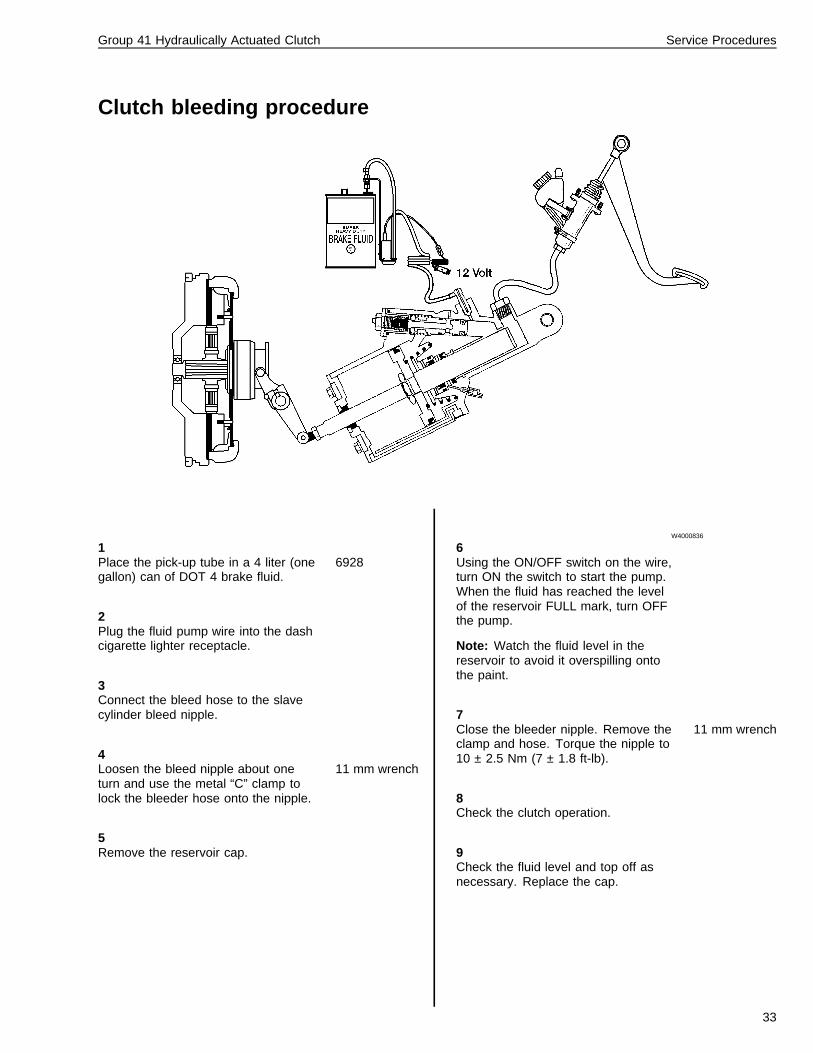
W4000836
1Place the pick-up tube in a 4 liter (onegallon) can of DOT 4 brake fluid.
6928
2Plug the fluid pump wire into the dashcigarette lighter receptacle.
3Connect the bleed hose to the slavecylinder bleed nipple.
4Loosen the bleed nipple about oneturn and use the metal “C” clamp tolock the bleeder hose onto the nipple.
11 mm wrench
5Remove the reservoir cap.
6Using the ON/OFF switch on the wire,turn ON the switch to start the pump.When the fluid has reached the levelof the reservoir FULL mark, turn OFFthe pump.
Note: Watch the fluid level in thereservoir to avoid it overspilling ontothe paint.
7Close the bleeder nipple. Remove theclamp and hose. Torque the nipple to10 ± 2.5 Nm (7 ± 1.8 ft-lb).
11 mm wrench
8Check the clutch operation.
9Check the fluid level and top off asnecessary. Replace the cap.
33
Group 41 Hydraulically Actuated Clutch Service Procedures
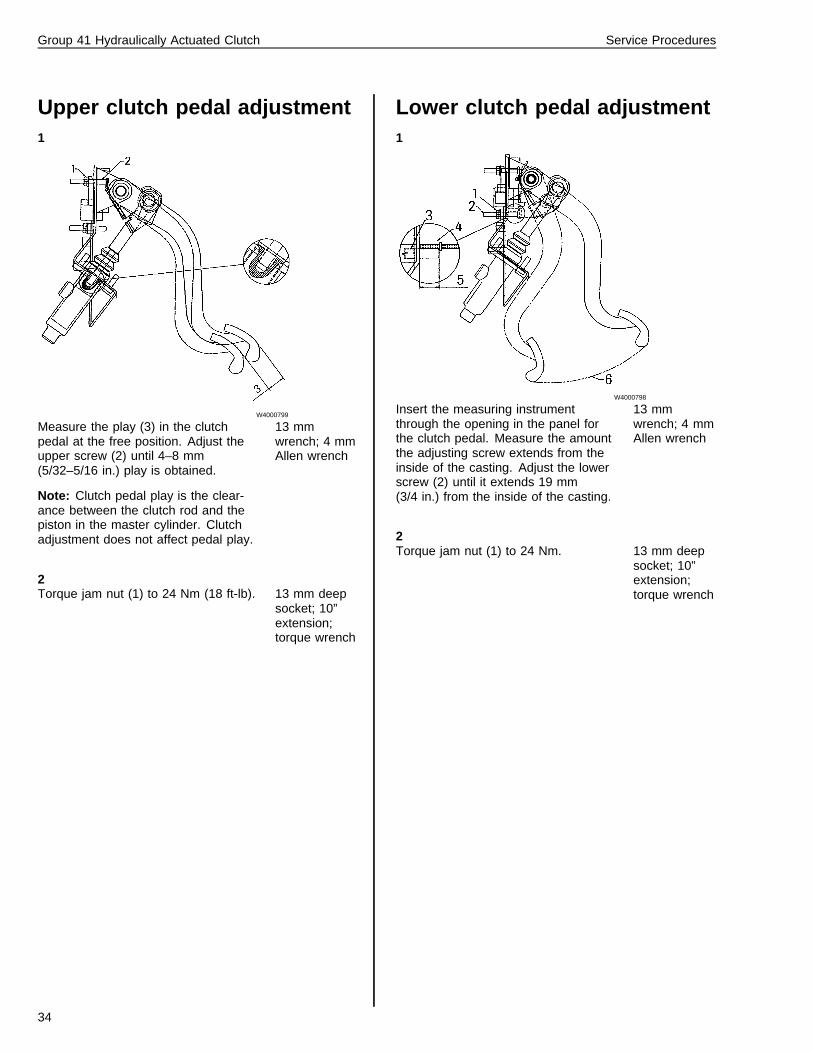
Upper clutch pedal adjustment1
W4000799
Measure the play (3) in the clutchpedal at the free position. Adjust theupper screw (2) until 4–8 mm(5/32–5/16 in.) play is obtained.
Note: Clutch pedal play is the clear-ance between the clutch rod and thepiston in the master cylinder. Clutchadjustment does not affect pedal play.
13 mmwrench; 4 mmAllen wrench
2Torque jam nut (1) to 24 Nm (18 ft-lb). 13 mm deep
socket; 10”extension;torque wrench
Lower clutch pedal adjustment1
W4000798
Insert the measuring instrumentthrough the opening in the panel forthe clutch pedal. Measure the amountthe adjusting screw extends from theinside of the casting. Adjust the lowerscrew (2) until it extends 19 mm(3/4 in.) from the inside of the casting.
13 mmwrench; 4 mmAllen wrench
2Torque jam nut (1) to 24 Nm. 13 mm deep
socket; 10”extension;torque wrench
34
Group 41 Hydraulically Actuated Clutch Service Procedures
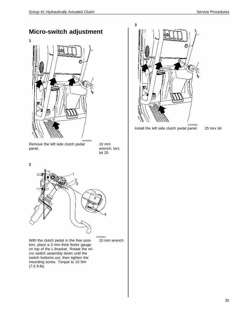
Micro-switch adjustment1
W4000855
Remove the left side clutch pedalpanel.
10 mmwrench; torxbit 25
2
W4000801
With the clutch pedal in the free posi-tion, place a 3 mm thick feeler gaugeon top of the L-bracket. Rotate the mi-cro switch assembly down until theswitch bottoms out, then tighten themounting screw. Torque to 10 Nm(7.5 ft-lb).
10 mm wrench
3
W4000855
Install the left side clutch pedal panel. 25 torx bit
35
Group 41 Hydraulically Actuated Clutch Service Procedures
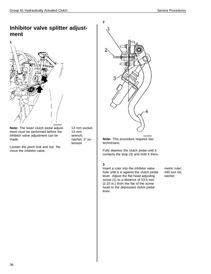
Inhibitor valve splitter adjust-ment1
W4000818
Note: The lower clutch pedal adjust-ment must be performed before theinhibitor valve adjustment can bemade.
Loosen the pinch bolt and nut. Re-move the inhibitor valve.
13 mm socket;13 mmwrench;ratchet; 3” ex-tension
2
W4000800
Note: This procedure requires twotechnicians.
Fully depress the clutch pedal until itcontacts the stop (3) and hold it there.
3Insert a ruler into the inhibitor valvehole until it is against the clutch pedallever. Adjust the flat head adjustingscrew (1) to a distance of 53.5 mm(2.10 in.) from the flat of the screwhead to the depressed clutch pedallever.
metric ruler;#40 torx bit;ratchet
36
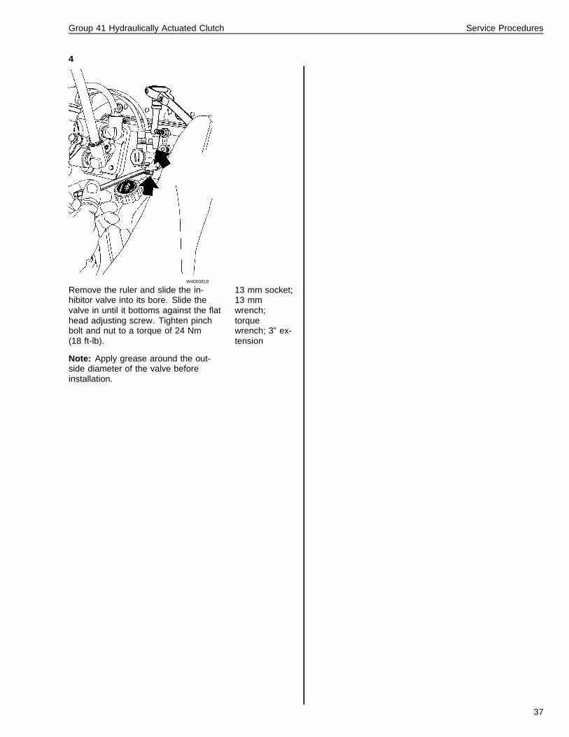
Group 41 Hydraulically Actuated Clutch Service Procedures
4
W4000818
Remove the ruler and slide the in-hibitor valve into its bore. Slide thevalve in until it bottoms against the flathead adjusting screw. Tighten pinchbolt and nut to a torque of 24 Nm(18 ft-lb).
Note: Apply grease around the out-side diameter of the valve beforeinstallation.
13 mm socket;13 mmwrench;torquewrench; 3” ex-tension
37
Group 41 Hydraulically Actuated Clutch Service Procedures
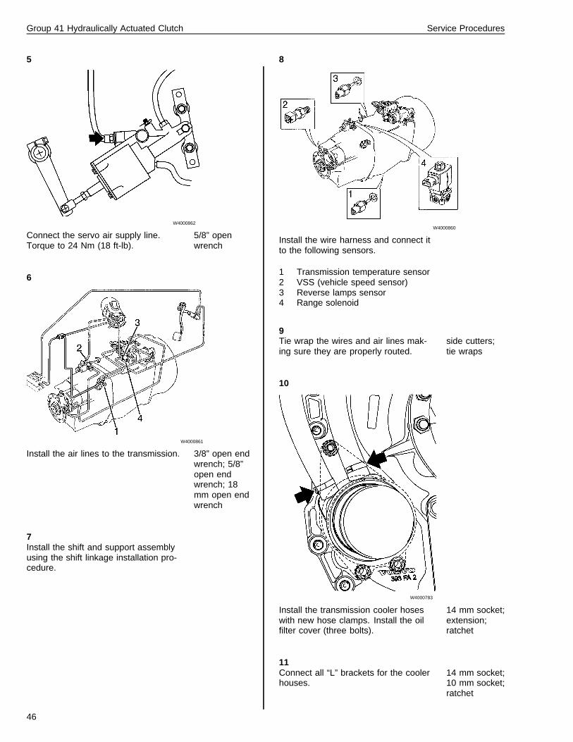
Transmission removal
Volvo transmissionOther special equipment: Transmission jack
1
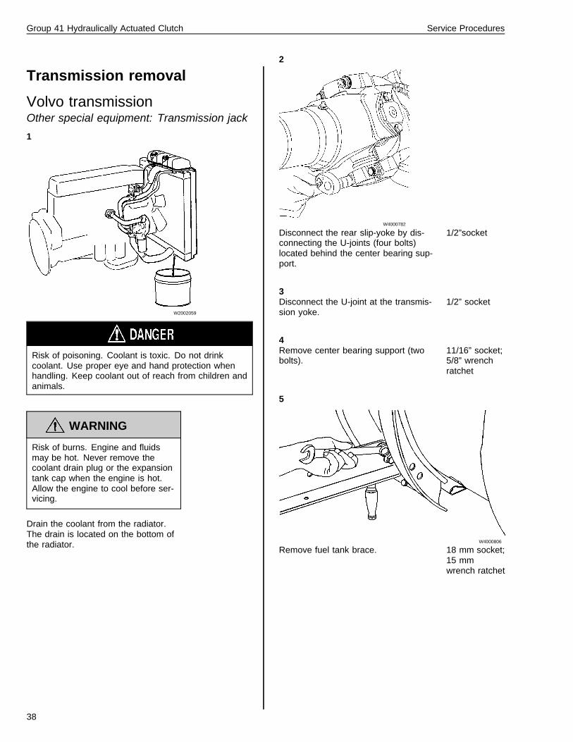
W2002059
Risk of poisoning. Coolant is toxic. Do not drinkcoolant. Use proper eye and hand protection whenhandling. Keep coolant out of reach from children andanimals.
WARNING
Risk of burns. Engine and fluidsmay be hot. Never remove thecoolant drain plug or the expansiontank cap when the engine is hot.Allow the engine to cool before ser-vicing.
Drain the coolant from the radiator.The drain is located on the bottom ofthe radiator.
2
W4000782
Disconnect the rear slip-yoke by dis-connecting the U-joints (four bolts)located behind the center bearing sup-port.
1/2”socket
3Disconnect the U-joint at the transmis-sion yoke.
1/2” socket
4Remove center bearing support (twobolts).
11/16” socket;5/8” wrenchratchet
5
W4000806
Remove fuel tank brace. 18 mm socket;15 mmwrench ratchet
38
Group 41 Hydraulically Actuated Clutch Service Procedures
6
W4000807
Remove the engine cross memberfrom the top cover of the engine nodalmounts.
18 mm socket/wrench; 15mm socket/wrench
7
W4000783
Remove the transmission oil filtercover to access the coolant hoses. Cutthe hose clamp to remove the hoses.
14 mm socket;side cutters
8Remove the coolant hose supportbrackets.
13 mm socket;10 mm socket;ratchet
9
W4000860
Disconnect the wire harness from thefollowing sensors and cut the wire ties.
1 Transmission temperature sensor2 VSS (vehicle speed sensor)3 Reverse lamps sensor4 Range solenoid
side cutters
10
W4000861
Remove air lines (1 through 4) and “L”brackets.
3/8” open endwrench; 5/8”open endwrench; 18mm open endwrench
39
Group 41 Hydraulically Actuated Clutch Service Procedures
11
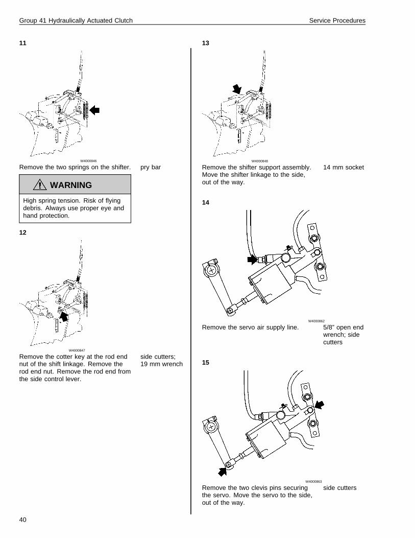
W4000846
Remove the two springs on the shifter.
WARNING
High spring tension. Risk of flyingdebris. Always use proper eye andhand protection.
pry bar
12
W4000847
Remove the cotter key at the rod endnut of the shift linkage. Remove therod end nut. Remove the rod end fromthe side control lever.
side cutters;19 mm wrench
13
W4000848
Remove the shifter support assembly.Move the shifter linkage to the side,out of the way.
14 mm socket
14
W4000862
Remove the servo air supply line. 5/8” open endwrench; sidecutters
15
W4000863
Remove the two clevis pins securingthe servo. Move the servo to the side,out of the way.
side cutters
40
Group 41 Hydraulically Actuated Clutch Service Procedures
16
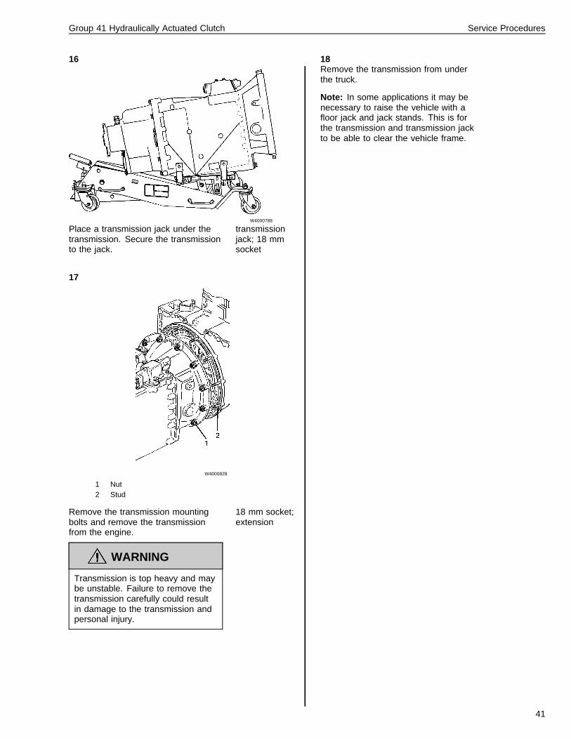
W4000788
Place a transmission jack under thetransmission. Secure the transmissionto the jack.
transmissionjack; 18 mmsocket
17
W4000828
1 Nut2 Stud
Remove the transmission mountingbolts and remove the transmissionfrom the engine.
WARNING
Transmission is top heavy and maybe unstable. Failure to remove thetransmission carefully could resultin damage to the transmission andpersonal injury.
18 mm socket;extension
18Remove the transmission from underthe truck.
Note: In some applications it may benecessary to raise the vehicle with afloor jack and jack stands. This is forthe transmission and transmission jackto be able to clear the vehicle frame.
41
Group 41 Hydraulically Actuated Clutch Service Procedures
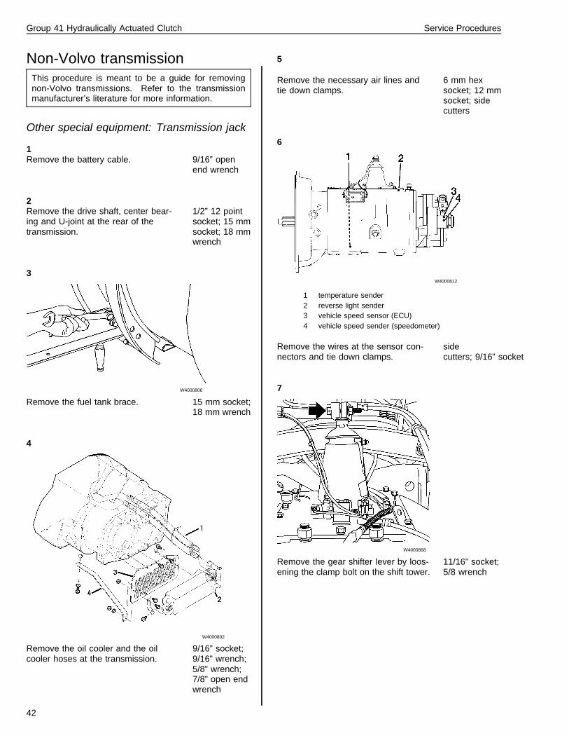
Non-Volvo transmissionThis procedure is meant to be a guide for removingnon-Volvo transmissions. Refer to the transmissionmanufacturer’s literature for more information.
Other special equipment: Transmission jack
1Remove the battery cable. 9/16” open
end wrench
2Remove the drive shaft, center bear-ing and U-joint at the rear of thetransmission.
1/2” 12 pointsocket; 15 mmsocket; 18 mmwrench
3
W4000806
Remove the fuel tank brace. 15 mm socket;18 mm wrench
4
W4000802
Remove the oil cooler and the oilcooler hoses at the transmission.
9/16” socket;9/16” wrench;5/8” wrench;7/8” open endwrench
5
Remove the necessary air lines andtie down clamps.
6 mm hexsocket; 12 mmsocket; sidecutters
6
W4000812
1 temperature sender2 reverse light sender3 vehicle speed sensor (ECU)4 vehicle speed sender (speedometer)
Remove the wires at the sensor con-nectors and tie down clamps.
sidecutters; 9/16” socket
7
W4000868
Remove the gear shifter lever by loos-ening the clamp bolt on the shift tower.
11/16” socket;5/8 wrench
42
Group 41 Hydraulically Actuated Clutch Service Procedures
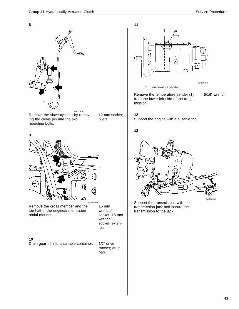
8
W4000870
Remove the slave cylinder by remov-ing the clevis pin and the twomounting bolts.
12 mm socket;pliers
9
W4000807
Remove the cross member and thetop half of the engine/transmissionnodal mounts.
15 mmwrench/socket; 18 mmwrench/socket; exten-sion
10Drain gear oil into a suitable container. 1/2” drive
ratchet; drainpan
11
W4000869
1 temperature sender
Remove the temperature sender (1)from the lower left side of the trans-mission.
5/16” wrench
12Support the engine with a suitable tool.
13
W4000808
Support the transmission with thetransmission jack and secure thetransmission to the jack.
43
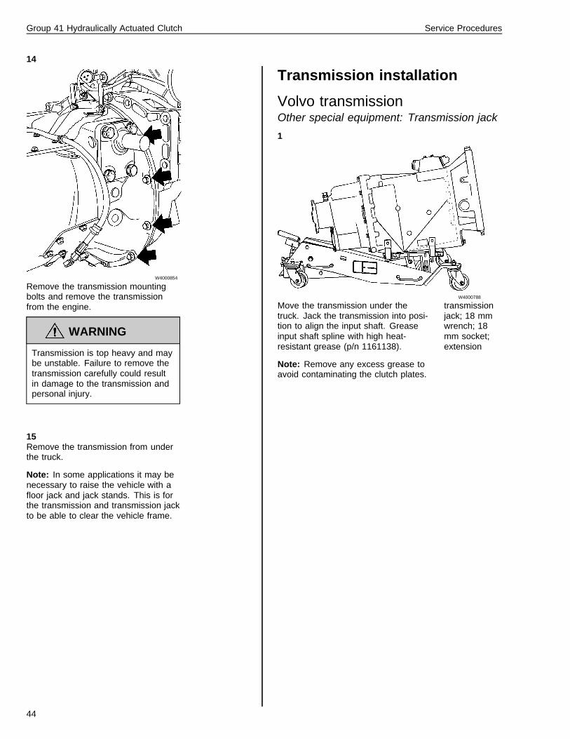
Group 41 Hydraulically Actuated Clutch Service Procedures
14
W4000854
Remove the transmission mountingbolts and remove the transmissionfrom the engine.
WARNING
Transmission is top heavy and maybe unstable. Failure to remove thetransmission carefully could resultin damage to the transmission andpersonal injury.
15Remove the transmission from underthe truck.
Note: In some applications it may benecessary to raise the vehicle with afloor jack and jack stands. This is forthe transmission and transmission jackto be able to clear the vehicle frame.
Transmission installation
Volvo transmissionOther special equipment: Transmission jack
1
W4000788
Move the transmission under thetruck. Jack the transmission into posi-tion to align the input shaft. Greaseinput shaft spline with high heat-resistant grease (p/n 1161138).
Note: Remove any excess grease toavoid contaminating the clutch plates.
transmissionjack; 18 mmwrench; 18mm socket;extension
44
Group 41 Hydraulically Actuated Clutch Service Procedures
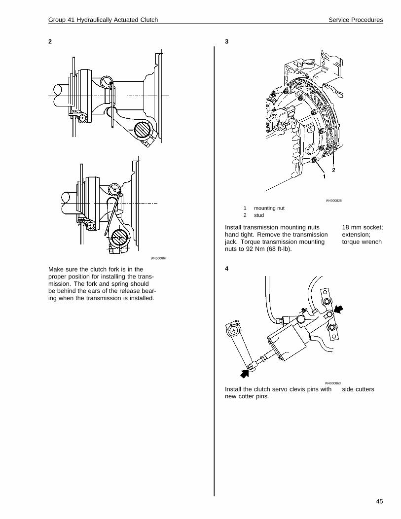
2
W4000864
Make sure the clutch fork is in theproper position for installing the trans-mission. The fork and spring shouldbe behind the ears of the release bear-ing when the transmission is installed.
3
W4000828
1 mounting nut2 stud
Install transmission mounting nutshand tight. Remove the transmissionjack. Torque transmission mountingnuts to 92 Nm (68 ft-lb).
18 mm socket;extension;torque wrench
4
W4000863
Install the clutch servo clevis pins withnew cotter pins.
side cutters
45
Group 41 Hydraulically Actuated Clutch Service Procedures
5
W4000862
Connect the servo air supply line.Torque to 24 Nm (18 ft-lb).
5/8” openwrench
6
W4000861
Install the air lines to the transmission. 3/8” open endwrench; 5/8”open endwrench; 18mm open endwrench
7Install the shift and support assemblyusing the shift linkage installation pro-cedure.
8
W4000860
Install the wire harness and connect itto the following sensors.
1 Transmission temperature sensor2 VSS (vehicle speed sensor)3 Reverse lamps sensor4 Range solenoid
9Tie wrap the wires and air lines mak-ing sure they are properly routed.
side cutters;tie wraps
10
W4000783
Install the transmission cooler hoseswith new hose clamps. Install the oilfilter cover (three bolts).
14 mm socket;extension;ratchet
11Connect all “L” brackets for the coolerhouses.
14 mm socket;10 mm socket;ratchet
46
Group 41 Hydraulically Actuated Clutch Service Procedures
12
W4000807
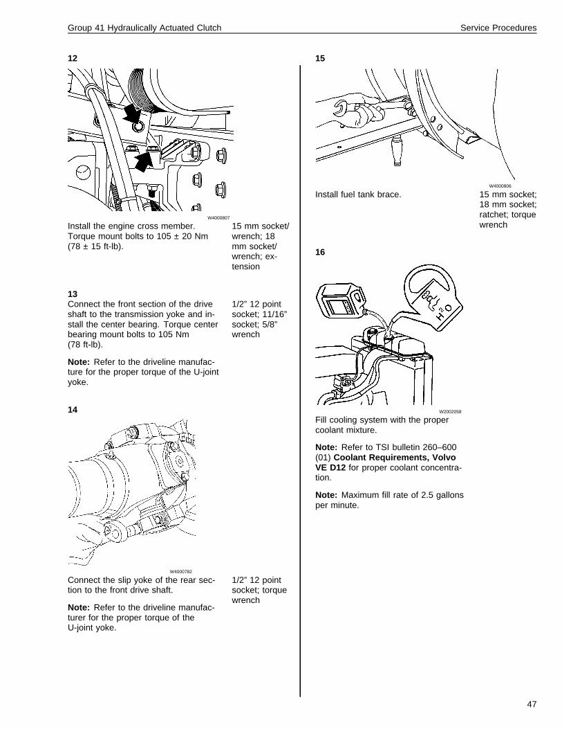
Install the engine cross member.Torque mount bolts to 105 ± 20 Nm(78 ± 15 ft-lb).
15 mm socket/wrench; 18mm socket/wrench; ex-tension
13Connect the front section of the driveshaft to the transmission yoke and in-stall the center bearing. Torque centerbearing mount bolts to 105 Nm(78 ft-lb).
Note: Refer to the driveline manufac-ture for the proper torque of the U-jointyoke.
1/2” 12 pointsocket; 11/16”socket; 5/8”wrench
14
W4000782
Connect the slip yoke of the rear sec-tion to the front drive shaft.
Note: Refer to the driveline manufac-turer for the proper torque of theU-joint yoke.
1/2” 12 pointsocket; torquewrench
15
W4000806
Install fuel tank brace. 15 mm socket;18 mm socket;ratchet; torquewrench
16
W2002058
Fill cooling system with the propercoolant mixture.
Note: Refer to TSI bulletin 260–600(01) Coolant Requirements, VolvoVE D12 for proper coolant concentra-tion.
Note: Maximum fill rate of 2.5 gallonsper minute.
47
Group 41 Hydraulically Actuated Clutch Service Procedures
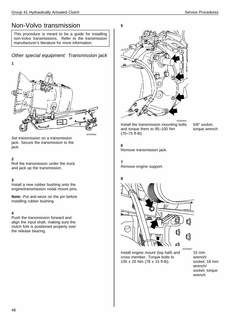
Non-Volvo transmissionThis procedure is meant to be a guide for installingnon-Volvo transmissions. Refer to the transmissionmanufacturer’s literature for more information.
Other special equipment: Transmission jack
1
W4000808
Set transmission on a transmissionjack. Secure the transmission to thejack.
2Roll the transmission under the truckand jack up the transmission.
3Install a new rubber bushing onto theengine/transmission nodal mount pins.
Note: Put anti-seize on the pin beforeinstalling rubber bushing.
4Push the transmission forward andalign the input shaft, making sure theclutch fork is positioned properly overthe release bearing.
5
W4000854
Install the transmission mounting boltsand torque them to 95–100 Nm(70–75 ft-lb).
5/8” socket;torque wrench
6Remove transmission jack.
7Remove engine support.
8
W4000807
Install engine mount (top half) andcross member. Torque bolts to105 ± 20 Nm (78 ± 15 ft-lb).
15 mmwrench/socket; 18 mmwrench/socket; torquewrench
48
Group 41 Hydraulically Actuated Clutch Service Procedures
9
W4000871
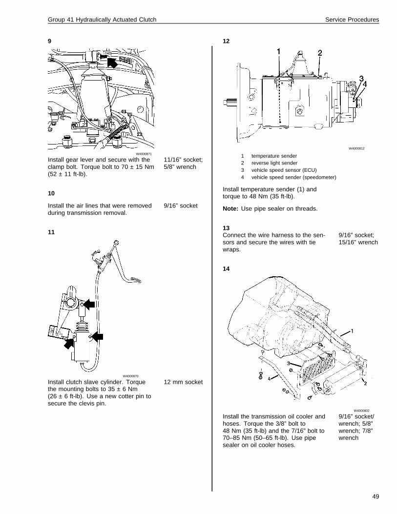
Install gear lever and secure with theclamp bolt. Torque bolt to 70 ± 15 Nm(52 ± 11 ft-lb).
11/16” socket;5/8” wrench
10
Install the air lines that were removedduring transmission removal.
9/16” socket
11
W4000870
Install clutch slave cylinder. Torquethe mounting bolts to 35 ± 6 Nm(26 ± 6 ft-lb). Use a new cotter pin tosecure the clevis pin.
12 mm socket
12
W4000812
1 temperature sender2 reverse light sender3 vehicle speed sensor (ECU)4 vehicle speed sender (speedometer)
Install temperature sender (1) andtorque to 48 Nm (35 ft-lb).
Note: Use pipe sealer on threads.
13Connect the wire harness to the sen-sors and secure the wires with tiewraps.
9/16” socket;15/16” wrench
14
W4000802
Install the transmission oil cooler andhoses. Torque the 3/8” bolt to48 Nm (35 ft-lb) and the 7/16” bolt to70–85 Nm (50–65 ft-lb). Use pipesealer on oil cooler hoses.
9/16” socket/wrench; 5/8”wrench; 7/8”wrench
49
Group 41 Hydraulically Actuated Clutch Service Procedures
15
W4000782
Install the drive shaft and center bear-ing. Center bearing to bracket; torqueto 105 Nm (78 ft-lb).
Note: Refer to the driveline manufac-turer for the proper torque values.
1/2” 12 pt.socket; 15 mmsocket; 18 mmwrench
16
W4000806
Install the fuel tank brace. 15 mm socket;18 mm wrench
17Fill the transmission with the manufac-turers recommended oil. Torque drainplug to 82–100 Nm (60–75 ft-lb).
9/16” wrench
18Install the battery cable.
19Road test the vehicle to check for oilleaks and air leaks.
Shift linkage removal1Remove the upper shift lever bootmounting bolts. Pull the upper andlower shift lever boots up on the shiftlever so work be carried out throughthe cab floor.
12 mm socket;6” extension
2
W4000849
Disconnect the air lines from the gearlever knob and cut the plastic ties.
10 mm openend wrench;18 mm openend wrench;side cutters
3
W4000847
Remove the cotter pin and nut fromthe rod end assembly.
19 mmwrench; sidecutters
4Remove the rod end assembly. Pulldown the rod end assembly until rodend is out of control lever. Releaseslowly to release spring tension. Dis-connect both springs.
hammer; balljoint separator
50
Group 41 Hydraulically Actuated Clutch Service Procedures
5Remove the nut from the control yokeat support assembly. Lift assemblyout.
19 mm socket
6
W4000865
Remove the three mounting bolts forthe support assembly, then removethe assembly.
14 mm socket
Shift linkage installation1
W4000848
Install the support assembly with threemounting bolts. Torque the two uppermounting bolts to 30 ± 5 Nm(22 ± 4 ft-lb). Torque the lower mount-ing bolt to 48 ± 8 Nm (35 ± 6 ft-lb).
14 mm socket;torque wrench
2
W4000866
Install the control assembly and nut.Connect the springs to the rod assem-bly. Torque the control assembly nutto 50 ± 10 Nm (37 ± 7 ft-lb).
19 mmwrench; sidecutter; 19 mmcrow’s foot;torque wrench
51
Group 41 Hydraulically Actuated Clutch Service Procedures
3
W4000847
Position the rod end into the controllever. Install the rod end nut and cot-ter pin. Torque the rod end nut to40 ± 10 Nm (30 ± 7 ft-lb).
19 mm socket;torque wrench
4
W4000849
Connect the air lines to the gear leverknob. Tie wrap the air lines.
1 – Purple / Supply3 – Yellow / Vent21 – Black / Range cylinder22– Blue / Splitter cylinder
10 mm openend wrench;18 mm openend wrench;side cutters
5Install the upper and lower shift bootsinto the proper positions. Install fourmounting bolts.
12 mm socket;6” extension;torque wrench
6Road test the vehicle to check forproper shift operation and air leaks.
52

53

Volvo GM Heavy Truck
Volvo GM Heavy Truck Corporation 7825 National Service Road P.O. Box 26115 Greensboro, NC 27402-6115Volvo GM Canada Heavy Truck Corp. 6490 Vipond Drive Mississauga, Ontario L5T 1W8
PV776-TSP24581/1 (1500) 10.96