Embed Size (px)
Citation preview
Service Manual
Caution: Federal Law (U.S.) restricts this device to sale or use by or on the order of a physician (or properly licensed practitioner).
Natus, neoBLUE and Bili-Meter are registered trademarks of Natus Medical Incorporated.
BiliBlanket is a registered trademark of GE Healthcare.
Joey is a registered trademark of Philips Healthcare.
© 2015 Natus Medical Incorporated. All rights reserved.
This manual may not be reprinted or copied in whole or in part without written consent from Natus Medical Incorporated. The content of this manual may change without notice.
Natus Medical Incorporated 5900 First Avenue South Seattle, WA 98108 USA Telephone +1 650 802 0400 Fax +1 650 802 0401
Technical Service +1 800 303 0306 Technical Service Fax +1 650 802 8680 E-mail: [email protected] Customer Service +1 800 303 0306 Customer Service Fax +1 650 802 6620 E-mail: [email protected]
International Support - Please contact your local Distributor. Distributor locations can be found at www.natus.com
EU Representative Natus Europe GmbH Robert-Koch-Str. 1 82152 Planegg Germany
Phototherapy System and Device: Patent Application Pending 10/265,9
Table of Contents
List of Figures 2
Chapter 1 Introduction 3
1.1 About this manual 3 1.2 Product description 5 1.3 Pictorial introduction to the neoBLUE system 5 1.4 Before you start 11 1.5 Contacting Natus Technical Support 12
Chapter 2 Routine Maintenance Procedures 13
2.1 Cleaning 14 2.2 Safety testing 15 2.3 Performance Verification 16 2.4 Adjusting light intensity 19
Chapter 3 Troubleshooting Guide 20
3.1 Troubleshooting the neoBLUE light 20 3.2 Troubleshooting the LED light current assembly 23
Chapter 4 Repair Procedures 26
4.1 Removing the lens 27 4.2 Removing the LED light panel 28 4.3 Removing components from the enclosure 29
Chapter 5 Parts and Specifications 32
5.1 How to order parts 32 5.2 Parts in context 32 5.3 Parts list 35 5.4 Illustrations of major parts 37 5.5 Accessory pack 39 5.6 Specifications 40
Chapter 6 Measuring the neoBLUE light with a radiometer 41
Chapter 7 Electromagnetic Specifications 42
neoBLUE® LED Phototherapy System Service Manual 1 PN 001320 Rev K
Chapter 1 Introduction
List of Figures
Figure 1-1 External, front view 6 Figure 1-2 External, rear view 6 Figure 1-3 Internal, view from top 8 Figure 1-4 Power supply 9 Figure 1-5 LED light current assembly 10 Figure 1-6 Block diagram 11 Figure 2-1 Locating the two filters on backside of enclosure 14 Figure 2-2 Measuring distance 18 Figure 2-3 Adjusting the potentiometers 19 Figure 4-1 Removing the lens 28 Figure 4-2 Removing the LED light panel 29 Figure 5-1 Enclosure and its attachments 33 Figure 5-2 Enclosure and its attachments 34 Figure 5-3 LED light panel (item # 1) 37 Figure 5-4 Enclosure (item # 2) 38 Figure 5-5 LED light current assembly (item # 3) 38
2 neoBLUE LED Phototherapy System Service Manual PN 001320 Rev K
Chapter 1 Introduction
In this chapter:
1.1 About this manual 1.2 Product description 1.3 Pictorial introduction to the neoBLUE system 1.4 Before you start 1.5 Contacting Natus Technical Support
1.1 About this manual
1.1.1 Overview
This manual contains information needed for servicing the neoBLUE Phototherapy System.
• Description of the product and overview illustrations (Chapter 1) • Maintenance procedures (Chapter 2) • Troubleshooting guide (Chapter 3) • Repair procedures (Chapter 4) • Parts and ordering information. (Chapter 5) • Measuring the neoBLUE light with a radiometer (Chapter 6) • Electromagnetic Specifications (Chapter 7)
1.1.2 Intended users
This service manual is written for qualified biomedical technicians. It describes service tasks which could lead to injury, or which could damage the device, if attempted by a person without the requisite skills.
1.1.3 Manual conventions
Precautionary information is emphasized by being labeled as warning, caution or important. Other explanatory information is highlighted with the word Note.
neoBLUE® LED Phototherapy System Service Manual 3 PN 001320 Rev K
Chapter 1 Introduction
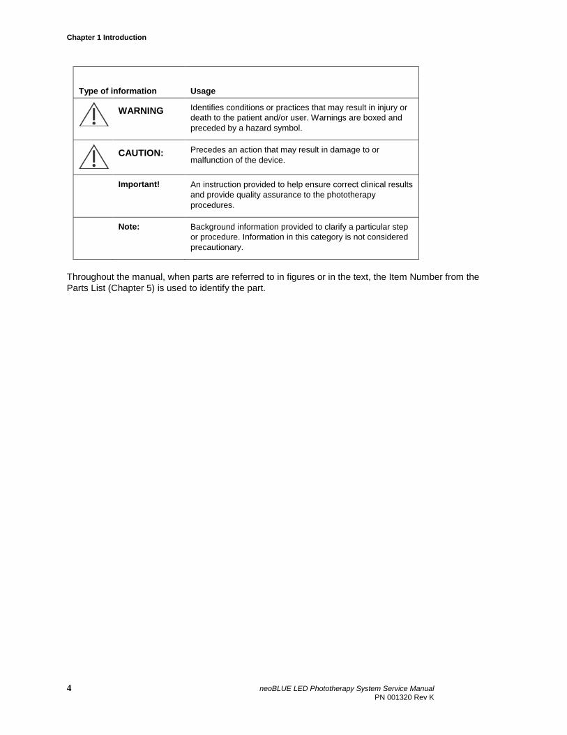
Type of information Usage
WARNING Identifies conditions or practices that may result in injury or death to the patient and/or user. Warnings are boxed and preceded by a hazard symbol.
CAUTION: Precedes an action that may result in damage to or
malfunction of the device.
Important! An instruction provided to help ensure correct clinical results and provide quality assurance to the phototherapy procedures.
Note: Background information provided to clarify a particular step or procedure. Information in this category is not considered precautionary.
Throughout the manual, when parts are referred to in figures or in the text, the Item Number from the Parts List (Chapter 5) is used to identify the part.
4 neoBLUE LED Phototherapy System Service Manual PN 001320 Rev K
1.2 Product description
The neoBLUE® LED Phototherapy System consists of two products – the neoBLUE Phototherapy light source (light) and the neoBLUE Phototherapy Roll Stand (roll stand). These components provide a floor-standing, mobile, phototherapy light that delivers a narrow band of high-intensity blue light via blue light emitting diodes (LEDs) to provide treatment for neonatal hyperbilirubinemia.
Blue LEDs emit light in the range of 400 – 550 nm (peak wavelength 450-475 nm). There are two light intensity settings, high and low. The light output was factory calibrated with the neoBLUE® Radiometer to provide an initial intensity of 35 µW/cm2/nm at the high setting and 15 µW/cm2/nm at the low setting at a distance of 12 inches (30.5 cm) from the light enclosure to the baby. The light output can also be adjusted using the two potentiometers (located on the side of the light enclosure) to accommodate different distances.
WARNING Eye Protection: Do not look directly into the LEDs. Some
people are sensitive to blue light in the environment. Amber safety glasses shield sensitive eyes, minimizing the effects of the blue light.
LEDs have minimal light output degradation over their lifetime with proper use. Nevertheless, the user can adjust the output of the LEDs for any degradation using the two potentiometers. Life testing has shown neoBLUE LEDs can emit high intensity phototherapy for over 40,000 hours. Actual results may vary based on environmental factors and adjustments to the potentiometers.
The roll stand is designed to hold 8 lbs of weight with a base designed to accommodate the weight distribution of the light enclosure at any height or angle.
WARNING If an alternative stand is used, care must be taken to validate
the load capacity.
The light is mains-power operated. The power cord plugs into a receptacle at the power inlet at the back of the light enclosure. A power cord strain relief bracket is provided to hold the power cord in place.
1.3 Pictorial introduction to the neoBLUE system
This section is meant to acquaint you with the various views of the neoBLUE light that you will see in the course of troubleshooting and repairing it. The item numbers and names used in the Parts List (see Chapter 5) are used throughout the book whenever parts are discussed.
These pictures show the front and rear views of the light enclosure, and internal views showing where the major components are located and some details. Also included is a block diagram.
neoBLUE® LED Phototherapy System Service Manual 5 PN 001320 Rev K
Chapter 1 Introduction
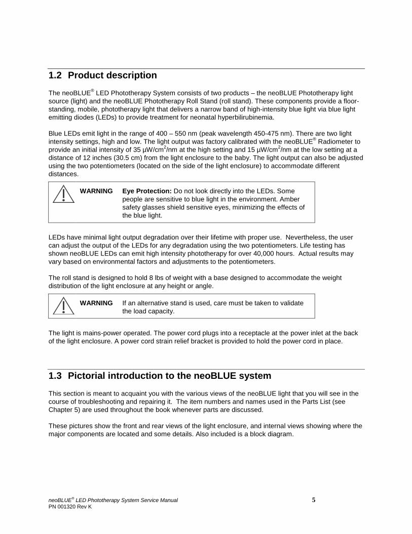
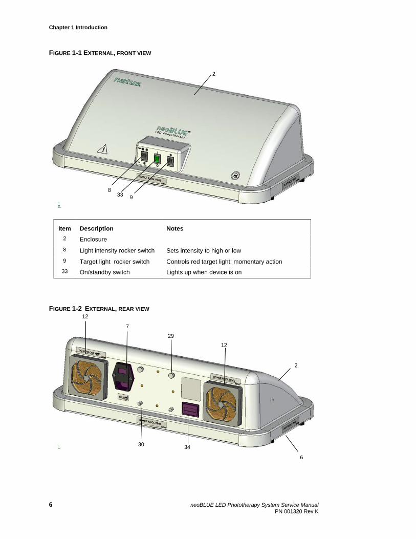
FIGURE 1-1 EXTERNAL, FRONT VIEW
Item Description Notes 2 Enclosure 8 Light intensity rocker switch Sets intensity to high or low 9 Target light rocker switch Controls red target light; momentary action 33 On/standby switch Lights up when device is on
FIGURE 1-2 EXTERNAL, REAR VIEW
8 33 9
2
12 7
29
6
12
34
30
2
6 neoBLUE LED Phototherapy System Service Manual PN 001320 Rev K
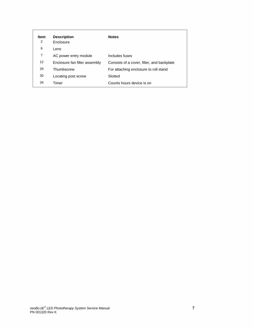
Item Description Notes 2 Enclosure 6 Lens 7 AC power entry module Includes fuses 12 Enclosure fan filter assembly Consists of a cover, filter, and backplate 29 Thumbscrew For attaching enclosure to roll stand 30 Locating post screw Slotted 34 Timer Counts hours device is on
neoBLUE® LED Phototherapy System Service Manual 7 PN 001320 Rev K
Chapter 1 Introduction
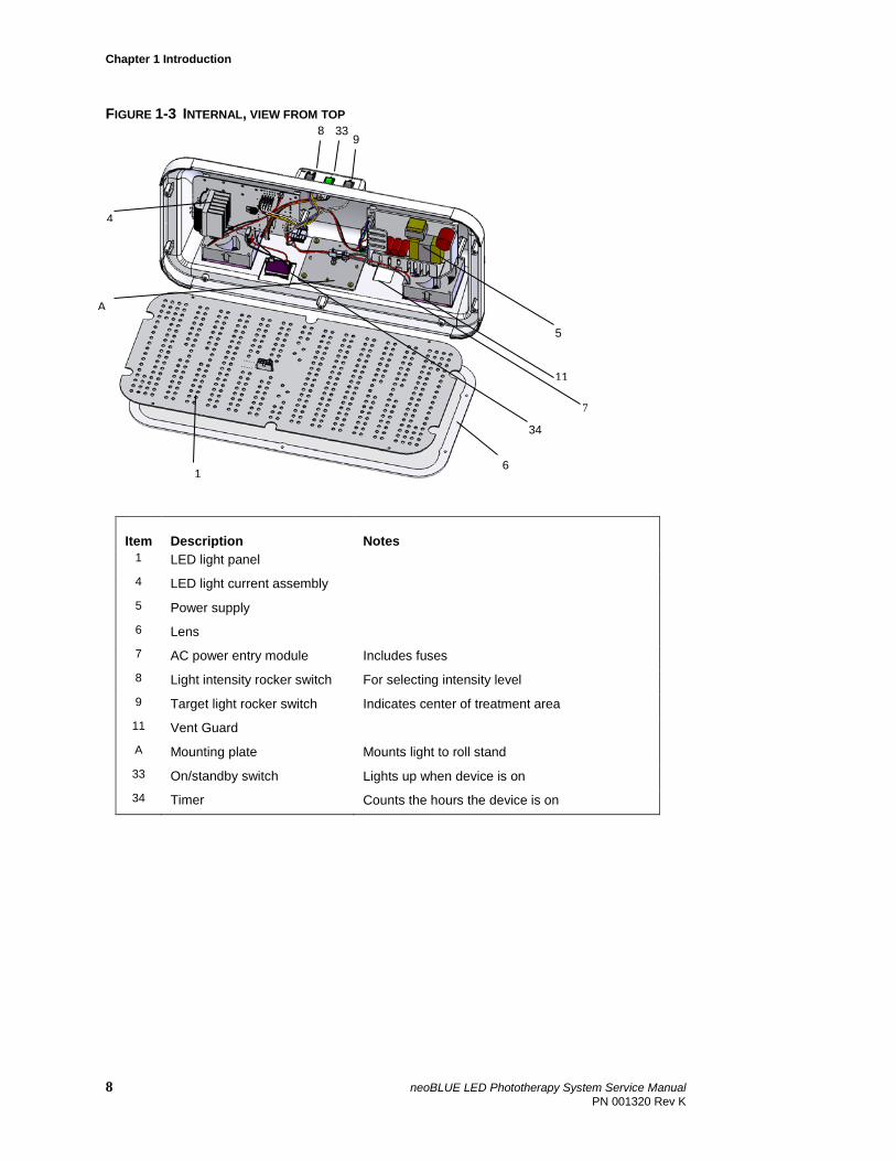
FIGURE 1-3 INTERNAL, VIEW FROM TOP
Item Description Notes 1 LED light panel 4 LED light current assembly 5 Power supply 6 Lens 7 AC power entry module Includes fuses 8 Light intensity rocker switch For selecting intensity level 9 Target light rocker switch Indicates center of treatment area 11 Vent Guard A Mounting plate Mounts light to roll stand 33 On/standby switch Lights up when device is on 34 Timer Counts the hours the device is on
8 33 9
A
11
34
4
6
5
1
7
8 neoBLUE LED Phototherapy System Service Manual PN 001320 Rev K
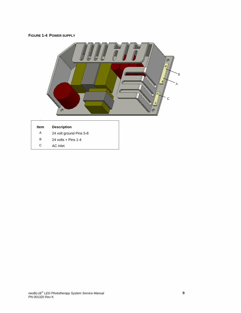
FIGURE 1-4 POWER SUPPLY
s
Item Description A 24 volt ground Pins 5-8 B 24 volts + Pins 1-4 C AC inlet
C
B
A
neoBLUE® LED Phototherapy System Service Manual 9 PN 001320 Rev K
Chapter 1 Introduction
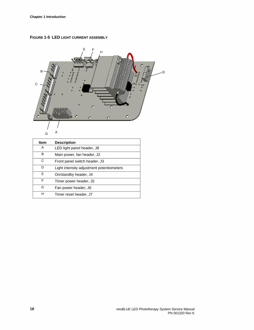
FIGURE 1-5 LED LIGHT CURRENT ASSEMBLY
Item Description A LED light panel header, J8 B Main power, fan header, J2 C Front panel switch header, J3 D Light intensity adjustment potentiometers E On/standby header, J4 F Timer power header, J5 G Fan power header, J6 H Timer reset header, J7
H E F
D
G
C
B
A
10 neoBLUE LED Phototherapy System Service Manual PN 001320 Rev K
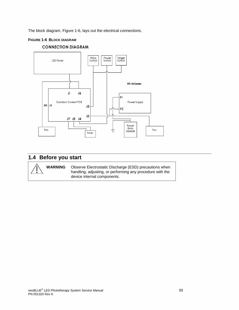
The block diagram, Figure 1-6, lays out the electrical connections.
FIGURE 1-6 BLOCK DIAGRAM
1.4 Before you start
WARNING Observe Electrostatic Discharge (ESD) precautions when
handling, adjusting, or performing any procedure with the device internal components.
neoBLUE® LED Phototherapy System Service Manual 11 PN 001320 Rev K
Chapter 1 Introduction
1.5 Contacting Natus Technical Support
Should you encounter situations that are not covered by this Service Manual, contact a Natus Technical Support representative.
Please have your Natus device model and serial number available when calling Technical Support.
Natus Medical Incorporated 5900 First Avenue South Seattle, WA 98108 USA Telephone +1 (650) 802-0400 Fax +1 (650) 802-0401 Technical Service +1 (800) 303-0306 Technical Service Fax +1 (650) 802 8680 E-mail [email protected] Customer Service +1 (800) 303-0306 Customer Service Fax +1 (650) 802 6620 E-mail [email protected] International Support- Please contact your local Distributor Distributor locations can be found at www.natus.com
EU Representative Natus Europe GmbH Robert-Koch-Str. 1 82152 Planegg Germany
12 neoBLUE LED Phototherapy System Service Manual PN 001320 Rev K
Chapter 2 Routine Maintenance Procedures
In this chapter: 2.1 Cleaning 2.2 Safety testing 2.3 Performance Verification 2.4 Adjusting light intensity
This chapter includes procedures for routine maintenance of the neoBLUE light, hereafter called the Unit Under Test (UUT). These procedures must be performed after any of the following events and/or as prescribed by the institution’s maintenance schedule:
• Initial receipt of the UUT at the institution.
• Foreign material or liquid has been deposited on the UUT.
• UUT has been visually damaged or subjected to mechanical shock (e.g., being dropped).
• UUT has been submitted for maintenance or scheduled performance verification.
neoBLUE® LED Phototherapy System Service Manual 13 PN 001320 Rev K
Chapter 2 Routine Maintenance Procedures
2.1 Cleaning
Cleaning the UUT incorporates two different tasks:
• Cleaning the light enclosure and accessories (Section 2.1.1)
• Cleaning the light enclosure air filters (Section 2.1.2)
WARNING Disconnect UUT from AC power before cleaning.
WARNING Biohazard. Until UUT is disinfected per institutional requirements, gloves and other appropriate safeguards must be employed.
CAUTION: Do not immerse the UUT or its accessories in liquid, or clean with caustic or abrasive cleaners. Do not spray or pour any liquid on the UUT enclosure.
2.1.1 Cleaning the light enclosure and accessories Clean the UUT enclosure using a cloth dampened with Germiocide™ or an equivalent product. Wipe the exterior plastic surfaces lightly. Do not allow any liquid to penetrate the power connector, switches, fans, connectors, or openings on the enclosure.
2.1.2 Cleaning the light enclosure air filters
The air filters should be cleaned at least every 30 days to prevent possible instrument overheating.
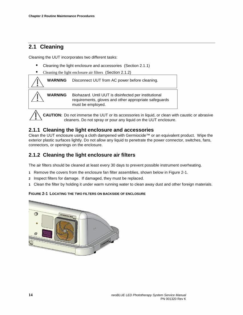
1 Remove the covers from the enclosure fan filter assemblies, shown below in Figure 2-1. 2 Inspect filters for damage. If damaged, they must be replaced. 1 Clean the filter by holding it under warm running water to clean away dust and other foreign materials.
FIGURE 2-1 LOCATING THE TWO FILTERS ON BACKSIDE OF ENCLOSURE
14 neoBLUE LED Phototherapy System Service Manual PN 001320 Rev K
4 Place the filter in a clean environment and allow it to air dry. The process can be expedited by having extra filters available for immediate replacement.
5 Return a dry filter to the fan assembly and press the filter cover firmly into place.
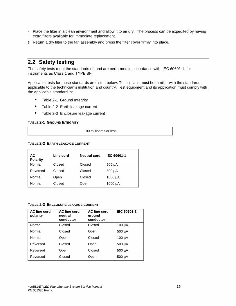
2.2 Safety testing The safety tests meet the standards of, and are performed in accordance with, IEC 60601-1, for instruments as Class 1 and TYPE BF.
Applicable tests for these standards are listed below. Technicians must be familiar with the standards applicable to the technician’s institution and country. Test equipment and its application must comply with the applicable standard in:
• Table 2-1 Ground Integrity
• Table 2-2 Earth leakage current
• Table 2-3 Enclosure leakage current
TABLE 2-1 GROUND INTEGRITY
100 milliohms or less
TABLE 2-2 EARTH LEAKAGE CURRENT
AC Polarity
Line cord
Neutral cord
IEC 60601-1
Normal Closed Closed 500 µA
Reversed Closed Closed 500 µA
Normal Open Closed 1000 µA
Normal Closed Open 1000 µA
TABLE 2-3 ENCLOSURE LEAKAGE CURRENT
AC line cord polarity
AC line cord neutral conductor
AC line cord ground conductor
IEC 60601-1
Normal Closed Closed 100 µA
Normal Closed Open 500 µA
Normal Open Closed 100 µA
Reversed Closed Open 500 µA
Reversed Open Closed 500 µA
Reversed Closed Open 500 µA
neoBLUE® LED Phototherapy System Service Manual 15 PN 001320 Rev K
Chapter 2 Routine Maintenance Procedures
2.3 Performance Verification
This section discusses the tests used to verify UUT performance
• Verifying general performance (Section 2.3.1)
• Checking the light intensity (Section 2.3.2)
All tests can be conducted without removing the UUT enclosure. If the UUT fails to conform or cannot be adjusted to conform, repairs must be made to correct the problem before the instrument is returned to the user.
TABLE 2-4 EQUIPMENT
Tools and test equipment Type
Screwdriver Phillips, medium
Radiometer neoBLUE Radiometer or equivalent (see Note below)
Potentiometer adjustment tool GC Electronics 8608 or small flat head screwdriver
Allen wrench 5/16” 90 degree or equivalent
Safety glasses Amber
Work pad Any non-abrasive non-static surface
Note: If a different radiometer is used, please refer to the Conversion Chart in chapter 6. If the meter is not listed, please contact Natus Technical Service before adjusting light intensity..
2.3.1 Verifying general performance 1 Turn off the Illuminated On/Standby switch and disconnect the AC power cord. 2 Remove the UUT from its roll stand by removing the thumbscrews, seen in Figure 1-2 on page 6. 3 Place the UUT on the work pad so the diffuser/LED light panel can be examined. Verify that the air
vents, Figure 2-1, are not blocked. 4 Connect the AC power cord to the UUT and to an AC receptacle.
WARNING It is strongly recommended the amber safety glasses be worn
at this time. Some people are affected by the blue color of the light source. The technician should notify others in the immediate area of this fact.
5 Place the light intensity rocker switch in the LOW position. Figure 1-1 on page 6 shows the location of the rocker switches.
6 Turn on the lighted On/Standby Switch. 7 Verify that the enclosure fans are running.
16 neoBLUE LED Phototherapy System Service Manual PN 001320 Rev K
8 Confirm that the LED light panel lights are on and operating properly.
• Confirm the presence of both blue and yellow LEDs lighted in rows.
• Examine panel geometry for uniform light spacing and unlighted LEDs. Note: The UUT can conform to specifications with some LEDs not lighted. However, if a large
number of LEDs are not lighted it may prevent the UUT from meeting minimum values required during testing. If enough LEDs are missing the LED intensity adjustment may need to be adjusted higher than necessary, which would reduce panel life.
• Press the target light rocker switch and verify that a diamond shaped group of RED LEDs is lighted in the center of the LED light panel. The light must extinguish when the rocker switch is released.
9 Verify that the Illuminated On/standby switch lights up. 10 Verify the timer is operating. The decimal point should be flashing if the device is on and not flashing
when the device is off. Turn off the UUT by turning off the Illuminated On/standby switch. 11 Check the light intensity. (See below.)
2.3.2 Checking the light intensity Important! Initial intensity measurements were factory calibrated with the neoBLUE® Radiometer and
were based on the patient being 12 inches (30.5 cm) from the light panel diffuser of the UUT. The light output can also be adjusted using the two potentiometers on the device (Section 2.4 Adjusting Light Intensity) to accommodate different distances. Adjusting the UUT light intensity higher will decrease expected LED light panel life.
Because your facility may use a different radiometer to measure the light intensity output, it is necessary to understand how your reading may differ from the neoBLUE Radiometer reading. Please refer to the Conversion Chart in chapter 6 for information on other meters.
neoBLUE® LED Phototherapy System Service Manual 17 PN 001320 Rev K
Chapter 2 Routine Maintenance Procedures
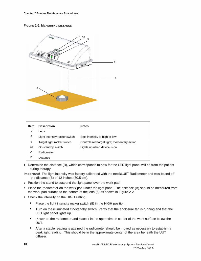
FIGURE 2-2 MEASURING DISTANCE
Item Description Notes 6 Lens 8 Light intensity rocker switch Sets intensity to high or low 9 Target light rocker switch Controls red target light; momentary action 33 On/standby switch Lights up when device is on A Radiometer B Distance
1 Determine the distance (B), which corresponds to how far the LED light panel will be from the patient during therapy.
Important! The light intensity was factory calibrated with the neoBLUE® Radiometer and was based off the distance (B) of 12 inches (30.5 cm).
2 Position the stand to suspend the light panel over the work pad. 3 Place the radiometer on the work pad under the light panel. The distance (B) should be measured from
the work pad surface to the bottom of the lens (6) as shown in Figure 2-2. 4 Check the intensity on the HIGH setting:
• Place the light intensity rocker switch (8) in the HIGH position.
• Turn on the illuminated On/standby switch. Verify that the enclosure fan is running and that the LED light panel lights up.
• Power on the radiometer and place it in the approximate center of the work surface below the UUT.
• After a stable reading is attained the radiometer should be moved as necessary to establish a peak light reading. This should be in the approximate center of the area beneath the UUT diffuser.
A
6
8 33
B
9
18 neoBLUE LED Phototherapy System Service Manual PN 001320 Rev K
Note: The radiometer should read 35 ±3.5 µW/cm2/nm at 12 inches (30.5 cm) based on the factory calibration. If the reading is not within the tolerance, note the value for use later in this procedure.
5 Check the intensity on the LOW setting:
• Place the light intensity rocker switch in the LOW position.
• Obtain a peak reading as in Step 4. Note: The radiometer should read 15 ±2 µW/cm2/nm at 12 inches (30.5 cm) based on the factory
calibration. If the reading is not within the tolerance, note the value for use later in this procedure.
6 If all criteria in the previous steps were met, the UUT performance has been verified and the UUT can be returned to the user. Turn off the UUT and ignore all further steps in this chapter.
7 If light intensity on either setting was not within tolerance, leave the test setup as is and proceed to Section 2.4 on page 22.
2.4 Adjusting light intensity
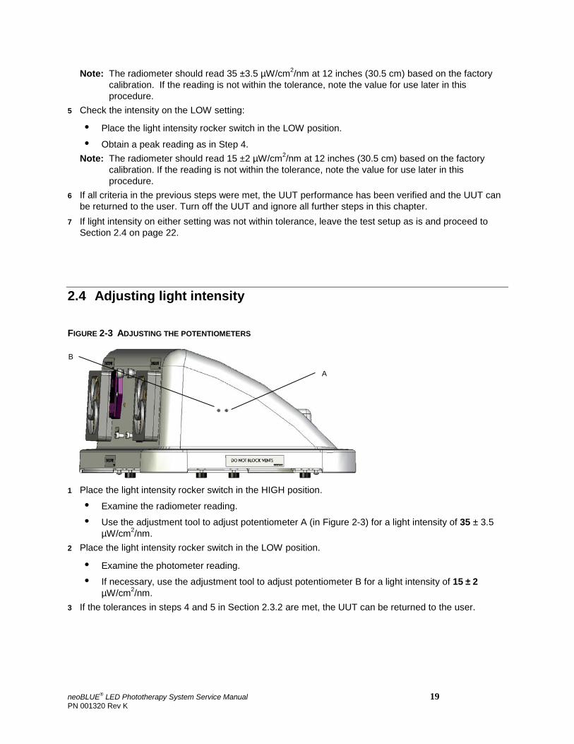
FIGURE 2-3 ADJUSTING THE POTENTIOMETERS
1 Place the light intensity rocker switch in the HIGH position.
• Examine the radiometer reading.
• Use the adjustment tool to adjust potentiometer A (in Figure 2-3) for a light intensity of 35 ± 3.5 µW/cm2/nm.
2 Place the light intensity rocker switch in the LOW position.
• Examine the photometer reading.
• If necessary, use the adjustment tool to adjust potentiometer B for a light intensity of 15 ± 2 µW/cm2/nm.
3 If the tolerances in steps 4 and 5 in Section 2.3.2 are met, the UUT can be returned to the user.
B
A
neoBLUE® LED Phototherapy System Service Manual 19 PN 001320 Rev K
Chapter 3 Troubleshooting Guide
Chapter 3 Troubleshooting Guide
In this chapter: 3.1 Troubleshooting the neoBLUE light 3.2 Troubleshooting the LED light current assembly
This chapter assumes that you are a qualified biomedical technician who is familiar with the neoBLUE light.
3.1 Troubleshooting the neoBLUE light
When opening the device, be sure to follow the procedures described in Chapter 4, as well as the steps and precautions in Section 2.2 on page 15 and Section 2.3 on page 16.
20 neoBLUE LED Phototherapy System Service Manual PN 001320 Rev K
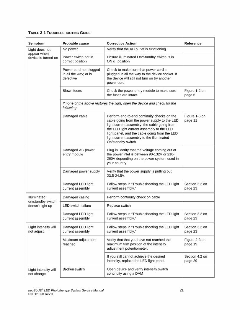
TABLE 3-1 TROUBLESHOOTING GUIDE
Symptom Probable cause Corrective Action Reference
Light does not appear when device is turned on
No power Verify that the AC outlet is functioning. Power switch not in correct position
Ensure illuminated On/Standby switch is in ON (|) position
Power cord not plugged in all the way; or is defective
Check to make sure that power cord is plugged in all the way to the device socket. If the device will still not turn on try another power cord.
Blown fuses Check the power entry module to make sure the fuses are intact.
Figure 1-2 on page 6
If none of the above restores the light, open the device and check for the following:
Damaged cable Perform end-to-end continuity checks on the cable going from the power supply to the LED light current assembly, the cable going from the LED light current assembly to the LED light panel, and the cable going from the LED light current assembly to the illuminated On/standby switch.
Figure 1-6 on page 11
Damaged AC power entry module
Plug in. Verify that the voltage coming out of the power inlet is between 90-132V or 210-260V depending on the power system used in your country.
Damaged power supply Verify that the power supply is putting out 23.5-24.5V.
Damaged LED light current assembly
Follow steps in “Troubleshooting the LED light current assembly.”
Section 3.2 on page 23
Illuminated on/standby switch doesn’t light up
Damaged casing Perform continuity check on cable
LED switch failure Replace switch
Damaged LED light current assembly
Follow steps in “Troubleshooting the LED light current assembly.”
Section 3.2 on page 23
Light intensity will not adjust
Damaged LED light current assembly
Follow steps in “Troubleshooting the LED light current assembly.”
Section 3.2 on page 23
Maximum adjustment reached
Verify that that you have not reached the maximum trim position of the intensity adjustment potentiometer.
Figure 2-3 on page 19
If you still cannot achieve the desired intensity, replace the LED light panel.
Section 4.2 on page 29
Light intensity will not change
Broken switch Open device and verify intensity switch continuity using a DVM
neoBLUE® LED Phototherapy System Service Manual 21 PN 001320 Rev K
Chapter 3 Troubleshooting Guide
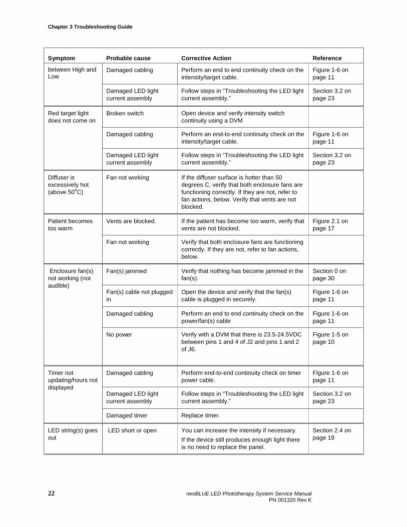
Symptom Probable cause Corrective Action Reference
between High and Low
Damaged cabling Perform an end to end continuity check on the intensity/target cable.
Figure 1-6 on page 11
Damaged LED light current assembly
Follow steps in “Troubleshooting the LED light current assembly.”
Section 3.2 on page 23
Red target light does not come on
Broken switch Open device and verify intensity switch continuity using a DVM
Damaged cabling Perform an end-to-end continuity check on the intensity/target cable.
Figure 1-6 on page 11
Damaged LED light current assembly
Follow steps in “Troubleshooting the LED light current assembly.”
Section 3.2 on page 23
Diffuser is excessively hot (above 50oC)
Fan not working If the diffuser surface is hotter than 50 degrees C, verify that both enclosure fans are functioning correctly. If they are not, refer to fan actions, below. Verify that vents are not blocked.
Patient becomes too warm
Vents are blocked. If the patient has become too warm, verify that vents are not blocked.
Figure 2.1 on page 17
Fan not working Verify that both enclosure fans are functioning correctly. If they are not, refer to fan actions, below.
Enclosure fan(s) not working (not audible)
Fan(s) jammed Verify that nothing has become jammed in the fan(s).
Section 0 on page 30
Fan(s) cable not plugged in
Open the device and verify that the fan(s) cable is plugged in securely.
Figure 1-6 on page 11
Damaged cabling Perform an end to end continuity check on the power/fan(s) cable
Figure 1-6 on page 11
No power Verify with a DVM that there is 23.5-24.5VDC between pins 1 and 4 of J2 and pins 1 and 2 of J6.
Figure 1-5 on page 10
Timer not updating/hours not displayed
Damaged cabling Perform end-to-end continuity check on timer power cable.
Figure 1-6 on page 11
Damaged LED light current assembly
Follow steps in “Troubleshooting the LED light current assembly.”
Section 3.2 on page 23
Damaged timer Replace timer.
LED string(s) goes out
LED short or open You can increase the intensity if necessary. If the device still produces enough light there is no need to replace the panel.
Section 2.4 on page 19
22 neoBLUE LED Phototherapy System Service Manual PN 001320 Rev K
Symptom Probable cause Corrective Action Reference
Multiple LED strings go out; cannot attain appropriate intensity
Damaged LED light panel
Replace LED light panel Section 4.2 on page 28
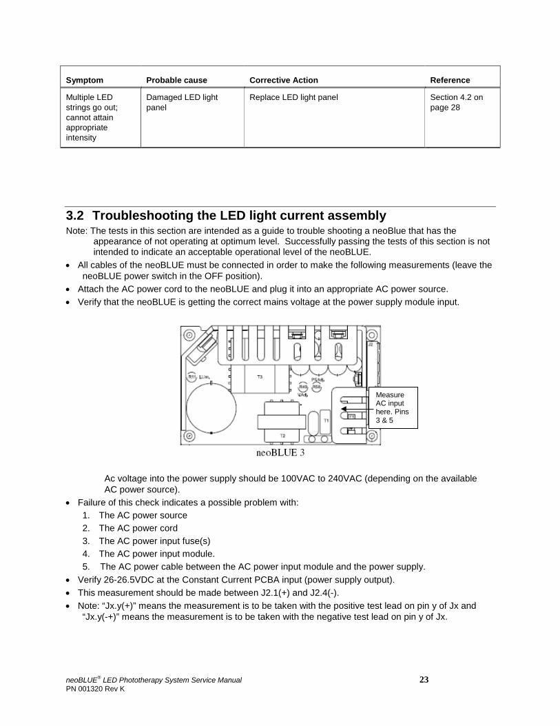
3.2 Troubleshooting the LED light current assembly Note: The tests in this section are intended as a guide to trouble shooting a neoBlue that has the
appearance of not operating at optimum level. Successfully passing the tests of this section is not intended to indicate an acceptable operational level of the neoBLUE.
• All cables of the neoBLUE must be connected in order to make the following measurements (leave the neoBLUE power switch in the OFF position).
• Attach the AC power cord to the neoBLUE and plug it into an appropriate AC power source. • Verify that the neoBLUE is getting the correct mains voltage at the power supply module input.
Ac voltage into the power supply should be 100VAC to 240VAC (depending on the available AC power source).
• Failure of this check indicates a possible problem with: 1. The AC power source 2. The AC power cord 3. The AC power input fuse(s) 4. The AC power input module. 5. The AC power cable between the AC power input module and the power supply.
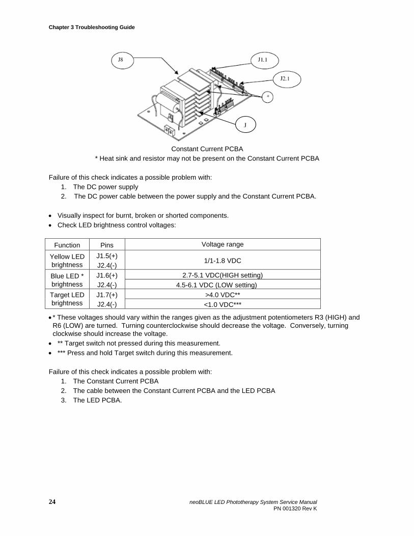
• Verify 26-26.5VDC at the Constant Current PCBA input (power supply output). • This measurement should be made between J2.1(+) and J2.4(-). • Note: “Jx.y(+)” means the measurement is to be taken with the positive test lead on pin y of Jx and
“Jx.y(-+)” means the measurement is to be taken with the negative test lead on pin y of Jx.
Measure AC input here. Pins 3 & 5
neoBLUE® LED Phototherapy System Service Manual 23 PN 001320 Rev K
Chapter 3 Troubleshooting Guide
Constant Current PCBA
* Heat sink and resistor may not be present on the Constant Current PCBA Failure of this check indicates a possible problem with:
1. The DC power supply 2. The DC power cable between the power supply and the Constant Current PCBA.
• Visually inspect for burnt, broken or shorted components. • Check LED brightness control voltages:
Function Pins Voltage range
Yellow LED brightness
J1.5(+) J2.4(-)
1/1-1.8 VDC
Blue LED * brightness
J1.6(+) J2.4(-)
2.7-5.1 VDC(HIGH setting) 4.5-6.1 VDC (LOW setting)
Target LED brightness
J1.7(+) J2.4(-)
>4.0 VDC** <1.0 VDC***
• * These voltages should vary within the ranges given as the adjustment potentiometers R3 (HIGH) and R6 (LOW) are turned. Turning counterclockwise should decrease the voltage. Conversely, turning clockwise should increase the voltage.
• ** Target switch not pressed during this measurement. • *** Press and hold Target switch during this measurement. Failure of this check indicates a possible problem with:
1. The Constant Current PCBA 2. The cable between the Constant Current PCBA and the LED PCBA 3. The LED PCBA.
J
24 neoBLUE LED Phototherapy System Service Manual PN 001320 Rev K
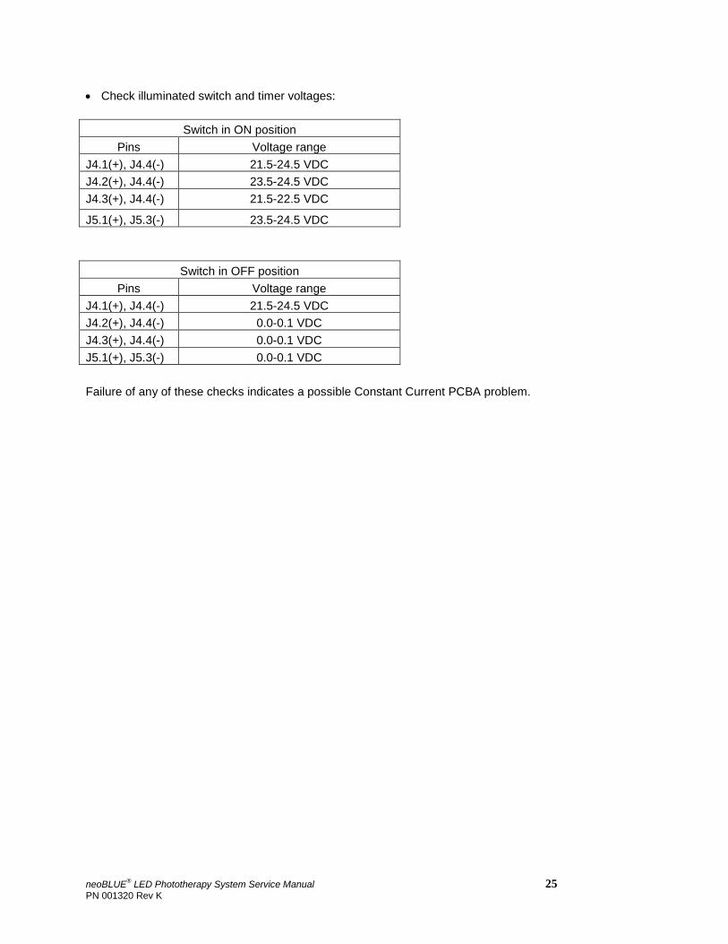
• Check illuminated switch and timer voltages:
Switch in ON position Pins Voltage range
J4.1(+), J4.4(-) 21.5-24.5 VDC J4.2(+), J4.4(-) 23.5-24.5 VDC J4.3(+), J4.4(-) 21.5-22.5 VDC
J5.1(+), J5.3(-) 23.5-24.5 VDC
Switch in OFF position Pins Voltage range
J4.1(+), J4.4(-) 21.5-24.5 VDC J4.2(+), J4.4(-) 0.0-0.1 VDC J4.3(+), J4.4(-) 0.0-0.1 VDC J5.1(+), J5.3(-) 0.0-0.1 VDC Failure of any of these checks indicates a possible Constant Current PCBA problem.
neoBLUE® LED Phototherapy System Service Manual 25 PN 001320 Rev K
Chapter 4 Repair Procedures
Chapter 4 Repair Procedures
In this chapter: 4.1 Removing the lens 4.2 Removing the LED light panel 4.3 Removing components from the enclosure
This chapter presents procedures for repairing the neoBLUE light, hereafter called the UUR (Unit Under Repair). Only qualified personnel should open the enclosure, remove and/or replace components or make adjustments. If your medical facility does not have qualified personnel, please contact Natus Technical Service for further assistance.
After any repair is completed and the UUR is reassembled, the technician must complete the safety tests and performance verification procedures listed in Section 2.2 on page 15 and Section 2.3 on page 16.
The UUR can be disassembled down to all major component parts.
26 neoBLUE LED Phototherapy System Service Manual PN 001320 Rev K
TABLE 4-1 EQUIPMENT
Tool Type
Screwdrivers Phillips, medium and flat head
Hex driver 1/16" deep socket
Wire cutters Medium
Work pad Any non-abrasive, non-static surface
WARNING Disconnect the AC power cord before beginning disassembly as high voltages can be encountered during disassembly.
CAUTION: Approved anti-static measures must be used anytime the UUR is disassembled.
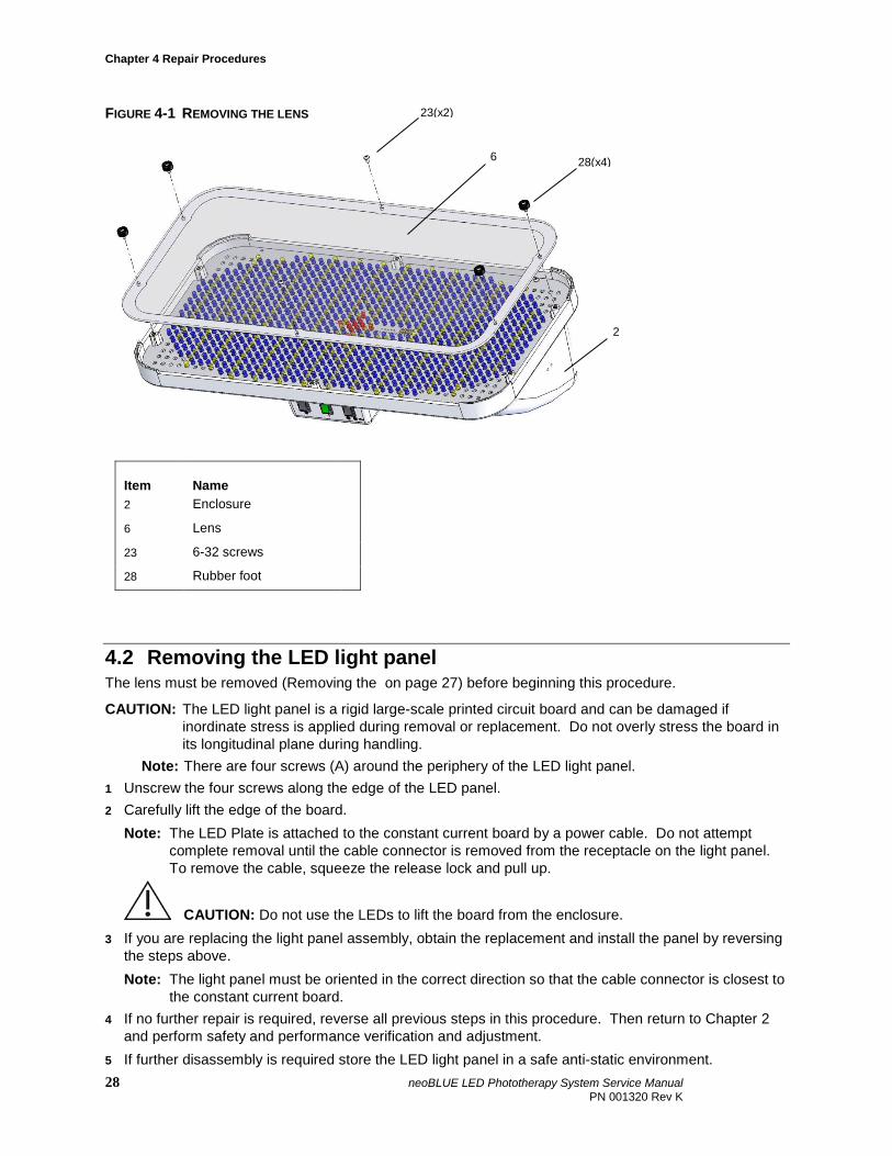
4.1 Removing the lens 1 Detach the UUR from its roll stand. 2 Place the UUR upside-down on a suitable work pad. 3 Remove the four rubber-foot screws around the bottom of the lens (6) and the two 6-32 screws from
the center edges of the lens. 4 Gently pull the lens away from the enclosure. Use caution. The lens is tightly fitted on the enclosure. 5 If you are replacing the lens, obtain the replacement and reverse the steps above to install the lens.
Note that the white silk-screened surface of the lens should be oriented toward the LED board.
WARNING The lens must be screwed in securely. Failing to secure the lens could cause injury to the patient if the lens itself or any internal components were to become loose and fall during therapy.
6 If no further repair is required, return to Chapter 2 and perform tests for Safety (Section 2.2 on page 15) and Performance Verification (Section 2.3 on page 16).
7 If further disassembly is required, store the lens in a protected area and proceed to Removing the LED light panel.
neoBLUE® LED Phototherapy System Service Manual 27 PN 001320 Rev K
Chapter 4 Repair Procedures
FIGURE 4-1 REMOVING THE LENS
Item Name 2 Enclosure
6 Lens
23 6-32 screws
28 Rubber foot
4.2 Removing the LED light panel The lens must be removed (Removing the on page 27) before beginning this procedure.
CAUTION: The LED light panel is a rigid large-scale printed circuit board and can be damaged if inordinate stress is applied during removal or replacement. Do not overly stress the board in its longitudinal plane during handling.
Note: There are four screws (A) around the periphery of the LED light panel. 1 Unscrew the four screws along the edge of the LED panel. 2 Carefully lift the edge of the board.
Note: The LED Plate is attached to the constant current board by a power cable. Do not attempt complete removal until the cable connector is removed from the receptacle on the light panel. To remove the cable, squeeze the release lock and pull up.
CAUTION: Do not use the LEDs to lift the board from the enclosure. 3 If you are replacing the light panel assembly, obtain the replacement and install the panel by reversing
the steps above. Note: The light panel must be oriented in the correct direction so that the cable connector is closest to
the constant current board. 4 If no further repair is required, reverse all previous steps in this procedure. Then return to Chapter 2
and perform safety and performance verification and adjustment. 5 If further disassembly is required store the LED light panel in a safe anti-static environment.
2
6
23(x2)
28(x4)
28 neoBLUE LED Phototherapy System Service Manual PN 001320 Rev K
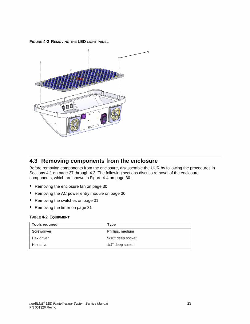
FIGURE 4-2 REMOVING THE LED LIGHT PANEL
4.3 Removing components from the enclosure Before removing components from the enclosure, disassemble the UUR by following the procedures in Sections 4.1 on page 27 through 4.2. The following sections discuss removal of the enclosure components, which are shown in Figure 4-4 on page 30.
• Removing the enclosure fan on page 30
• Removing the AC power entry module on page 30
• Removing the switches on page 31
• Removing the timer on page 31
TABLE 4-2 EQUIPMENT
Tools required Type
Screwdriver Phillips, medium
Hex driver 5/16" deep socket
Hex driver 1/4" deep socket
A
neoBLUE® LED Phototherapy System Service Manual 29 PN 001320 Rev K
Chapter 4 Repair Procedures
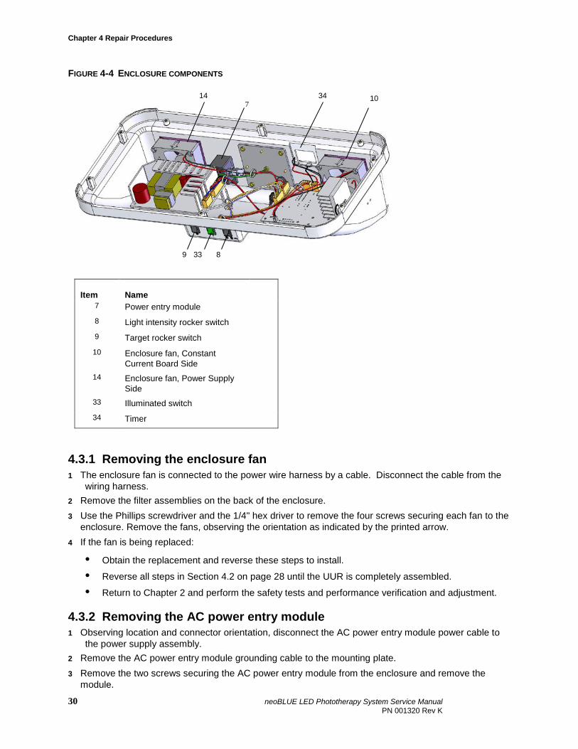
FIGURE 4-4 ENCLOSURE COMPONENTS
4.3.1 Removing the enclosure fan 1 The enclosure fan is connected to the power wire harness by a cable. Disconnect the cable from the
wiring harness. 2 Remove the filter assemblies on the back of the enclosure. 3 Use the Phillips screwdriver and the 1/4" hex driver to remove the four screws securing each fan to the
enclosure. Remove the fans, observing the orientation as indicated by the printed arrow. 4 If the fan is being replaced:
• Obtain the replacement and reverse these steps to install.
• Reverse all steps in Section 4.2 on page 28 until the UUR is completely assembled.
• Return to Chapter 2 and perform the safety tests and performance verification and adjustment.
4.3.2 Removing the AC power entry module 1 Observing location and connector orientation, disconnect the AC power entry module power cable to
the power supply assembly. 2 Remove the AC power entry module grounding cable to the mounting plate. 3 Remove the two screws securing the AC power entry module from the enclosure and remove the
module.
Item Name 7 Power entry module 8 Light intensity rocker switch 9 Target rocker switch 10 Enclosure fan, Constant
Current Board Side
14 Enclosure fan, Power Supply Side
33 Illuminated switch 34 Timer
8 33 9
34 14 7
10
30 neoBLUE LED Phototherapy System Service Manual PN 001320 Rev K
4 If the AC power entry module is being replaced:
• Obtain the replacement and reverse these steps to install.
• Reverse all steps in Section 4.2 on page 28 until the UUR is completely assembled.
• Return to Chapter 2 and perform the safety tests and performance verification and adjustment. Important! Ensure that the ground wire to plate is attached after either disassembling or re-assembling
the UUR.
4.3.3 Removing the switches 1 Disconnect the spade connectors from the switch to be removed. Take note of wire colors and
connections. 2 Remove the switch by compressing the spring fasteners on either side of the switch housing. The
switch can be pushed out the rear of the enclosure. 3 If a switch is being replaced:
• Obtain the replacement and reverse these steps to install.
• Reverse all steps in Section 4.2 on page 28 until the UUR is completely assembled.
• Return to Chapter 2 and perform the safety tests and performance verification and adjustment.
4.3.4 Removing the timer 1 Press the side tabs of the plastic clamp, holding the timer in, and pull back to free it from the timer. 2 Disconnect the spade connectors from the timer. 3 Disconnect the cable from the J7 header on the current PCB. 4 If the timer is being replaced:
• Obtain the replacement and reverse these steps to install.
• Return to Chapter 2 and perform the safety tests and performance verification and adjustment.
• Reverse all steps in Section 4.2 on page 28 until the UUR is completely assembled.
neoBLUE® LED Phototherapy System Service Manual 31 PN 001320 Rev K
Chapter 5 Parts and Specifications
Chapter 5 Parts and Specifications
In this chapter:
5.1 How to order parts 5.2 Parts in context 5.3 Parts list 5.4 Illustrations of major parts 5.5 Accessory pack 5.6 Specifications
5.1 How to order parts
Call Technical Service at 1-888-496-2887 to order parts or for general technical information. A minimum order may be required for spare parts. The list of product specifications in this chapter will guide you in making purchases from vendors other than Natus.
5.2 Parts in context
Two views of the neoBLUE light appear below, to show you where the parts are and how they fit together. The views are:
• Enclosure and its attachments: The enclosure holds the enclosure fans and vents, the switches, AC power entry module, and the access holes to the calibration potentiometers. It is mounted to the roll stand.
32 neoBLUE LED Phototherapy System Service Manual PN 001320 Rev K
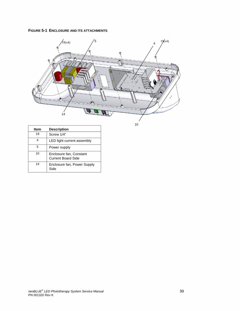
FIGURE 5-1 ENCLOSURE AND ITS ATTACHMENTS
Item Description 19 Screw 1/4” 4 LED light current assembly
5 Power supply
10 Enclosure fan, Constant Current Board Side
14 Enclosure fan, Power Supply Side
5
14
4
19(x4)
19(x4)
10
neoBLUE® LED Phototherapy System Service Manual 33 PN 001320 Rev K

Chapter 5 Parts and Specifications
FIGURE 5-2 ENCLOSURE AND ITS ATTACHMENTS
Item Description Item Description 2 Enclosure 20 Screw, 1 / 4” 7 AC power entry module 21 Nut, 5/16” 8 Light intensity switch 22 Screw, 1 3/4” 9 Target rocker switch 24 Screw, 5/8” 10 Fan Enclosure, Power Supply
side 29 Thumbscrew
11 Vent guard 30 Locating post screw 1 2 Enclosure fan filter assembly 33 Illuminated on/standby switch 14 Fan Enclosure, CCB side 34 Timer
2
7
8 33 9
14
11
12
34
21(x4)
29(x2) 30(x2)
24(x2)
22(x4)
20 10
21(x4)
34 neoBLUE LED Phototherapy System Service Manual PN 001320 Rev K
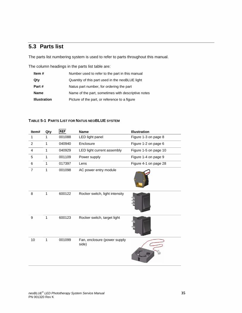
5.3 Parts list
The parts list numbering system is used to refer to parts throughout this manual.
The column headings in the parts list table are:
Item # Number used to refer to the part in this manual
Qty Quantity of this part used in the neoBLUE light
Part # Natus part number, for ordering the part
Name Name of the part, sometimes with descriptive notes
Illustration Picture of the part, or reference to a figure
TABLE 5-1 PARTS LIST FOR NATUS NEOBLUE SYSTEM
Item# Qty Name Illustration 1 1 001088 LED light panel Figure 1-3 on page 8
2 1 040940 Enclosure Figure 1-2 on page 6
4 1 040929 LED light current assembly Figure 1-5 on page 10
5 1 001109 Power supply Figure 1-4 on page 9
6 1 017397 Lens Figure 4-1 on page 28
7 1 001098 AC power entry module
8 1 600122 Rocker switch, light intensity
9 1 600123 Rocker switch, target light
10 1 001099 Fan, enclosure (power supply side)
neoBLUE® LED Phototherapy System Service Manual 35 PN 001320 Rev K
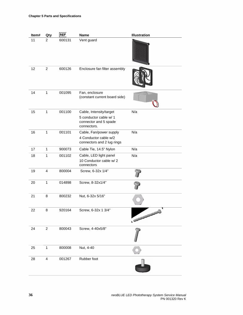
Chapter 5 Parts and Specifications
Item# Qty Name Illustration 11 2 600131 Vent guard
12 2 600126 Enclosure fan filter assembly
14 1 001095 Fan, enclosure (constant current board side)
15 1 001100 Cable, Intensity/target 5 conductor cable w/ 1 connector and 5 spade connectors.
N/a
16 1 001101 Cable, Fan/power supply 4 Conductor cable w/2 connectors and 2 lug rings
N/a
17 1 900073 Cable Tie, 14.5" Nylon N/a
18 1 001102 Cable, LED light panel 10 Conductor cable w/ 2 connectors
N/a
19 4 800004 Screw, 6-32x 1/4”
20 1 014898 Screw, 8-32x1/4”
21 8 800232 Nut, 6-32x 5/16”
22 8 920164 Screw, 6-32x 1 3/4”
24 2 800043 Screw, 4-40x5/8”
25 1 800008 Nut, 4-40
28 4 001267 Rubber foot
36 neoBLUE LED Phototherapy System Service Manual PN 001320 Rev K
Item# Qty Name Illustration 29 2 800226 Thumbscrew, 8-32
30 2 001352 Screw, Locating post
32 1 040757 Accessory pack Section 5.5 on page 39.
33 1 600167 Switch, Illuminated, Green
34 1 900831 Timer, single display
35 1 040892 Cable, Power for timer, 2
conductors with 1 connector and 2 spade connectors
36 1 001097 Cable, On/standby switch, 4
conductors with 1 connector and 4 spade connectors
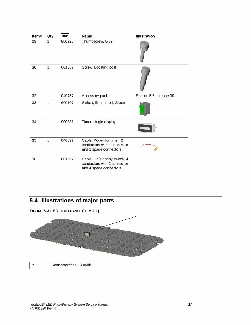
5.4 Illustrations of major parts FIGURE 5-3 LED LIGHT PANEL (ITEM # 1)
A Connector for LED cable
neoBLUE® LED Phototherapy System Service Manual 37 PN 001320 Rev K
Chapter 5 Parts and Specifications
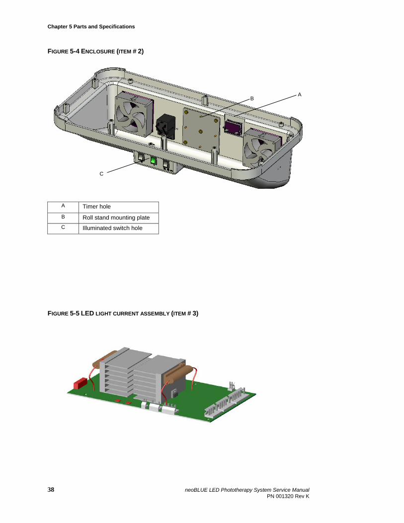
FIGURE 5-4 ENCLOSURE (ITEM # 2)
A Timer hole
B Roll stand mounting plate C Illuminated switch hole
FIGURE 5-5 LED LIGHT CURRENT ASSEMBLY (ITEM # 3)
B
C
A
38 neoBLUE LED Phototherapy System Service Manual PN 001320 Rev K
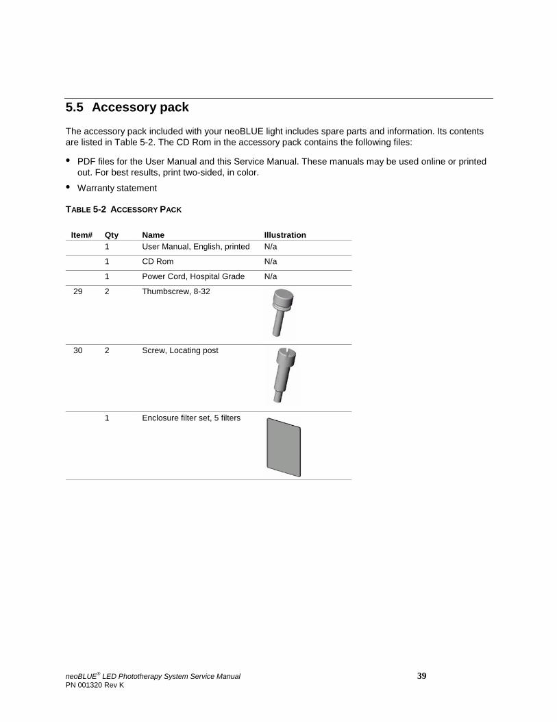
5.5 Accessory pack
The accessory pack included with your neoBLUE light includes spare parts and information. Its contents are listed in Table 5-2. The CD Rom in the accessory pack contains the following files:
• PDF files for the User Manual and this Service Manual. These manuals may be used online or printed out. For best results, print two-sided, in color.
• Warranty statement
TABLE 5-2 ACCESSORY PACK
Item# Qty Name Illustration 1 User Manual, English, printed N/a
1 CD Rom N/a
1 Power Cord, Hospital Grade N/a
29 2 Thumbscrew, 8-32
30 2 Screw, Locating post
1 Enclosure filter set, 5 filters
neoBLUE® LED Phototherapy System Service Manual 39 PN 001320 Rev K
Chapter 5 Parts and Specifications
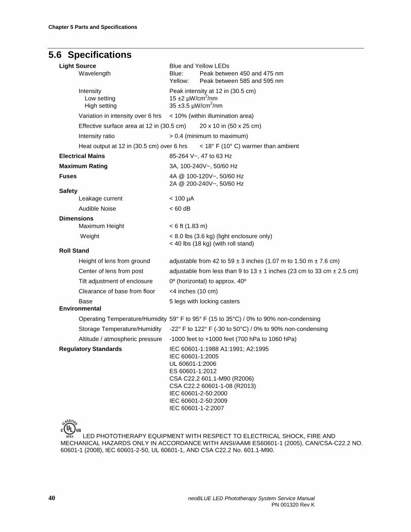
5.6 Specifications Light Source Blue and Yellow LEDs Wavelength Blue: Peak between 450 and 475 nm
Yellow: Peak between 585 and 595 nm
Intensity Peak intensity at 12 in (30.5 cm) Low setting 15 ±2 µW/cm2/nm High setting 35 ±3.5 µW/cm2/nm
Variation in intensity over 6 hrs < 10% (within illumination area)
Effective surface area at 12 in (30.5 cm) 20 x 10 in (50 x 25 cm)
Intensity ratio > 0.4 (minimum to maximum)
Heat output at 12 in (30.5 cm) over 6 hrs < 18° F (10° C) warmer than ambient Electrical Mains 85-264 V~, 47 to 63 Hz
Maximum Rating 3A, 100-240V~, 50/60 Hz
Fuses 4A @ 100-120V~, 50/60 Hz 2A @ 200-240V~, 50/60 Hz Safety Leakage current < 100 µA
Audible Noise < 60 dB Dimensions Maximum Height < 6 ft (1.83 m)
Weight < 8.0 lbs (3.6 kg) (light enclosure only) < 40 lbs (18 kg) (with roll stand)
Roll Stand Height of lens from ground adjustable from 42 to 59 ± 3 inches (1.07 m to 1.50 m ± 7.6 cm)
Center of lens from post adjustable from less than 9 to 13 ± 1 inches (23 cm to 33 cm ± 2.5 cm)
Tilt adjustment of enclosure 0º (horizontal) to approx. 40º
Clearance of base from floor <4 inches (10 cm)
Base 5 legs with locking casters Environmental Operating Temperature/Humidity 59° F to 95° F (15 to 35°C) / 0% to 90% non-condensing
Storage Temperature/Humidity -22° F to 122° F (-30 to 50°C) / 0% to 90% non-condensing
Altitude / atmospheric pressure -1000 feet to +1000 feet (700 hPa to 1060 hPa) Regulatory Standards IEC 60601-1:1988 A1:1991; A2:1995 IEC 60601-1:2005 UL 60601-1:2006 ES 60601-1:2012 CSA C22.2 601.1-M90 (R2006) CSA C22.2 60601-1-08 (R2013) IEC 60601-2-50:2000 IEC 60601-2-50:2009 IEC 60601-1-2:2007
LED PHOTOTHERAPY EQUIPMENT WITH RESPECT TO ELECTRICAL SHOCK, FIRE AND MECHANICAL HAZARDS ONLY IN ACCORDANCE WITH ANSI/AAMI ES60601-1 (2005), CAN/CSA-C22.2 NO. 60601-1 (2008), IEC 60601-2-50, UL 60601-1, AND CSA C22.2 No. 601.1-M90.
40 neoBLUE LED Phototherapy System Service Manual PN 001320 Rev K
Chapter 6 Measuring the neoBLUE light with a radiometer
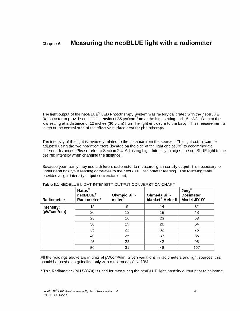
The light output of the neoBLUE® LED Phototherapy System was factory calibrated with the neoBLUE Radiometer to provide an initial intensity of 35 µW/cm2/nm at the high setting and 15 µW/cm2/nm at the low setting at a distance of 12 inches (30.5 cm) from the light enclosure to the baby. This measurement is taken at the central area of the effective surface area for phototherapy.
The intensity of the light is inversely related to the distance from the source. The light output can be adjusted using the two potentiometers (located on the side of the light enclosure) to accommodate different distances. Please refer to Section 2.4, Adjusting Light Intensity to adjust the neoBLUE light to the desired intensity when changing the distance.
Because your facility may use a different radiometer to measure light intensity output, it is necessary to understand how your reading correlates to the neoBLUE Radiometer reading. The following table provides a light intensity output conversion chart, Table 6.1 NEOBLUE LIGHT INTENSITY OUTPUT CONVERSTION CHART
Radiometer:
Natus® neoBLUE® Radiometer *
Olympic Bili- meter®
Ohmeda Bili- blanket® Meter II
Joey® Dosimeter Model JD100
Intensity: (µW/cm2/nm)
15 9 14 32 20 13 19 43 25 16 23 53 30 19 28 64 35 22 32 75 40 25 37 86 45 28 42 96 50 31 46 107
All the readings above are in units of µW/cm²/nm. Given variations in radiometers and light sources, this should be used as a guideline only with a tolerance of +/- 10%. * This Radiometer (P/N 53870) is used for measuring the neoBLUE light intensity output prior to shipment.
neoBLUE® LED Phototherapy System Service Manual 41 PN 001320 Rev K
Chapter 7 Electromagnetic Specifications
Chapter 7 Electromagnetic Specifications
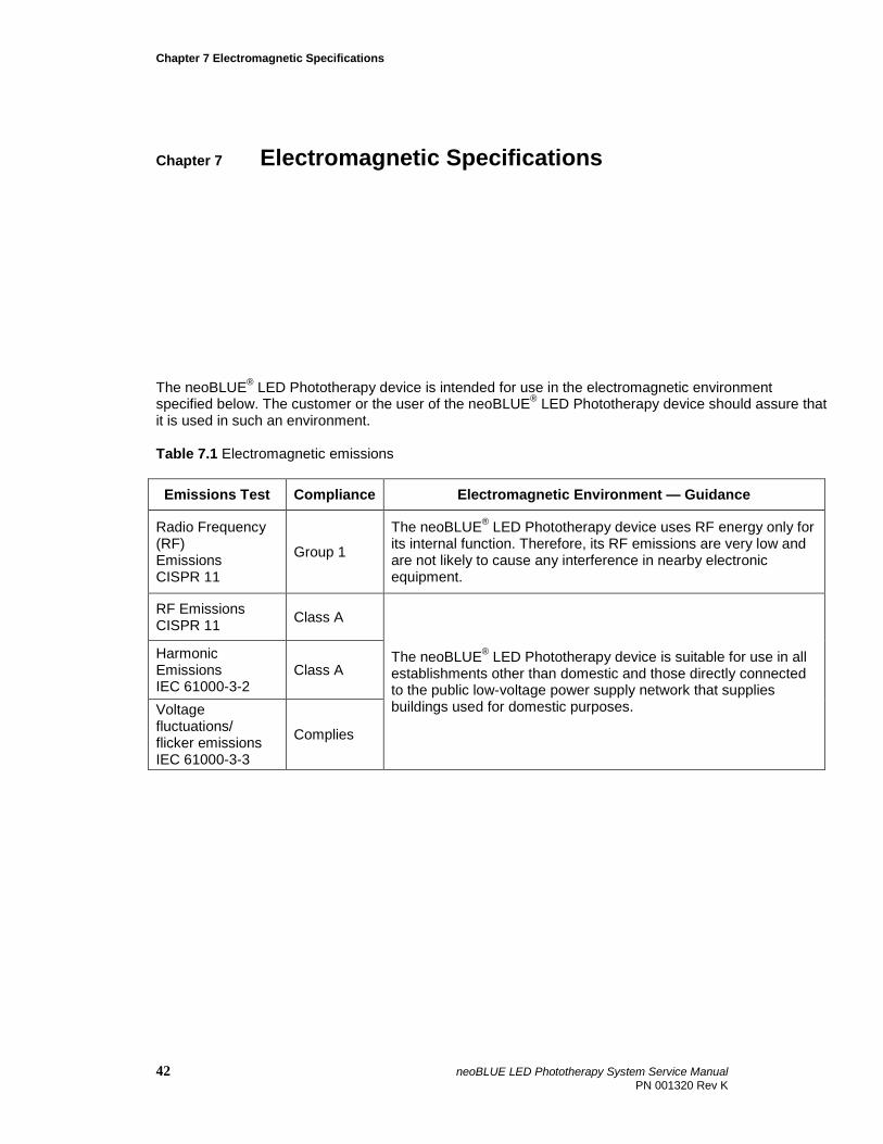
The neoBLUE® LED Phototherapy device is intended for use in the electromagnetic environment specified below. The customer or the user of the neoBLUE® LED Phototherapy device should assure that it is used in such an environment. Table 7.1 Electromagnetic emissions
Emissions Test Compliance Electromagnetic Environment — Guidance
Radio Frequency (RF) Emissions CISPR 11
Group 1
The neoBLUE® LED Phototherapy device uses RF energy only for its internal function. Therefore, its RF emissions are very low and are not likely to cause any interference in nearby electronic equipment.
RF Emissions CISPR 11 Class A
The neoBLUE® LED Phototherapy device is suitable for use in all establishments other than domestic and those directly connected to the public low-voltage power supply network that supplies buildings used for domestic purposes.
Harmonic Emissions IEC 61000-3-2
Class A
Voltage fluctuations/ flicker emissions IEC 61000-3-3
Complies
42 neoBLUE LED Phototherapy System Service Manual PN 001320 Rev K
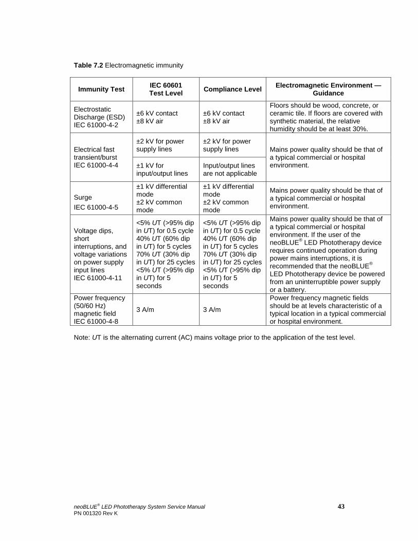
Table 7.2 Electromagnetic immunity
Immunity Test IEC 60601 Test Level Compliance Level Electromagnetic Environment —
Guidance
Electrostatic Discharge (ESD) IEC 61000-4-2
±6 kV contact ±8 kV air
±6 kV contact ±8 kV air
Floors should be wood, concrete, or ceramic tile. If floors are covered with synthetic material, the relative humidity should be at least 30%.
Electrical fast transient/burst IEC 61000-4-4
±2 kV for power supply lines
±2 kV for power supply lines Mains power quality should be that of
a typical commercial or hospital environment. ±1 kV for
input/output lines Input/output lines are not applicable
Surge IEC 61000-4-5
±1 kV differential mode ±2 kV common mode
±1 kV differential mode ±2 kV common mode
Mains power quality should be that of a typical commercial or hospital environment.
Voltage dips, short interruptions, and voltage variations on power supply input lines IEC 61000-4-11
<5% UT (>95% dip in UT) for 0.5 cycle 40% UT (60% dip in UT) for 5 cycles 70% UT (30% dip in UT) for 25 cycles <5% UT (>95% dip in UT) for 5 seconds
<5% UT (>95% dip in UT) for 0.5 cycle 40% UT (60% dip in UT) for 5 cycles 70% UT (30% dip in UT) for 25 cycles <5% UT (>95% dip in UT) for 5 seconds
Mains power quality should be that of a typical commercial or hospital environment. If the user of the neoBLUE® LED Phototherapy device requires continued operation during power mains interruptions, it is recommended that the neoBLUE® LED Phototherapy device be powered from an uninterruptible power supply or a battery.
Power frequency (50/60 Hz) magnetic field IEC 61000-4-8
3 A/m 3 A/m
Power frequency magnetic fields should be at levels characteristic of a typical location in a typical commercial or hospital environment.
Note: UT is the alternating current (AC) mains voltage prior to the application of the test level.
neoBLUE® LED Phototherapy System Service Manual 43 PN 001320 Rev K
Chapter 7 Electromagnetic Specifications
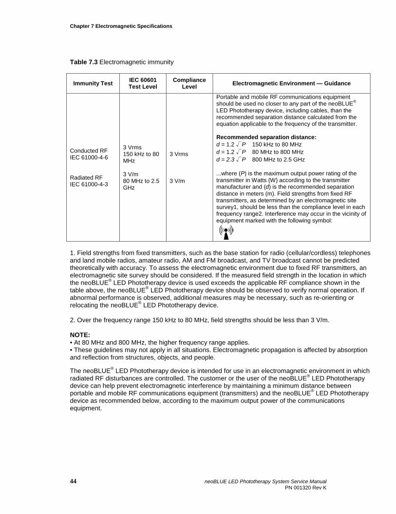
Table 7.3 Electromagnetic immunity
Immunity Test IEC 60601 Test Level
Compliance Level Electromagnetic Environment — Guidance
Conducted RF IEC 61000-4-6 Radiated RF IEC 61000-4-3
3 Vrms 150 kHz to 80 MHz 3 V/m 80 MHz to 2.5 GHz
3 Vrms 3 V/m
Portable and mobile RF communications equipment should be used no closer to any part of the neoBLUE® LED Phototherapy device, including cables, than the recommended separation distance calculated from the equation applicable to the frequency of the transmitter. Recommended separation distance: d = 1.2 √P 150 kHz to 80 MHz d = 1.2 √P 80 MHz to 800 MHz d = 2.3 √P 800 MHz to 2.5 GHz ...where (P) is the maximum output power rating of the transmitter in Watts (W) according to the transmitter manufacturer and (d) is the recommended separation distance in meters (m). Field strengths from fixed RF transmitters, as determined by an electromagnetic site survey1, should be less than the compliance level in each frequency range2. Interference may occur in the vicinity of equipment marked with the following symbol:
1. Field strengths from fixed transmitters, such as the base station for radio (cellular/cordless) telephones and land mobile radios, amateur radio, AM and FM broadcast, and TV broadcast cannot be predicted theoretically with accuracy. To assess the electromagnetic environment due to fixed RF transmitters, an electromagnetic site survey should be considered. If the measured field strength in the location in which the neoBLUE® LED Phototherapy device is used exceeds the applicable RF compliance shown in the table above, the neoBLUE® LED Phototherapy device should be observed to verify normal operation. If abnormal performance is observed, additional measures may be necessary, such as re-orienting or relocating the neoBLUE® LED Phototherapy device. 2. Over the frequency range 150 kHz to 80 MHz, field strengths should be less than 3 V/m. NOTE: • At 80 MHz and 800 MHz, the higher frequency range applies. • These guidelines may not apply in all situations. Electromagnetic propagation is affected by absorption and reflection from structures, objects, and people. The neoBLUE® LED Phototherapy device is intended for use in an electromagnetic environment in which radiated RF disturbances are controlled. The customer or the user of the neoBLUE® LED Phototherapy device can help prevent electromagnetic interference by maintaining a minimum distance between portable and mobile RF communications equipment (transmitters) and the neoBLUE® LED Phototherapy device as recommended below, according to the maximum output power of the communications equipment.
44 neoBLUE LED Phototherapy System Service Manual PN 001320 Rev K
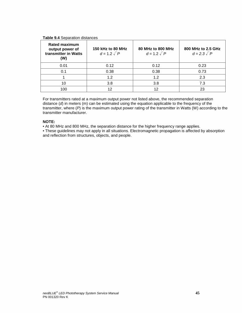
Table 9.4 Separation distances
Rated maximum output power of
transmitter in Watts (W)
150 kHz to 80 MHz d = 1.2 √P
80 MHz to 800 MHz d = 1.2 √P
800 MHz to 2.5 GHz d = 2.3 √P
0.01 0.12 0.12 0.23 0.1 0.38 0.38 0.73 1 1.2 1.2 2.3
10 3.8 3.8 7.3 100 12 12 23
For transmitters rated at a maximum output power not listed above, the recommended separation distance (d) in meters (m) can be estimated using the equation applicable to the frequency of the transmitter, where (P) is the maximum output power rating of the transmitter in Watts (W) according to the transmitter manufacturer. NOTE: • At 80 MHz and 800 MHz, the separation distance for the higher frequency range applies. • These guidelines may not apply in all situations. Electromagnetic propagation is affected by absorption and reflection from structures, objects, and people.
neoBLUE® LED Phototherapy System Service Manual 45 PN 001320 Rev K