Embed Size (px)
Citation preview

Service Manual
IMPORTANT: READ SAFETY RULES AND INSTRUCTIONS CAREFULLY
PRINTED IN USA FORM NO.769-00967
This Service Manual is not a substitute for the Operator’s Manual. You must read, understand and follow all of the directions in this manual as well as the Operator’s Manual before working on this power equipment.
(11/2003)
CUB CADET LLC, P.O. BOX 361131, CLEVELAND, OH 44136-0019
Cub Cadet Z-Force
www.mymowerparts.com
K&T Saw Shop 606-678-9623 or 606-561-4983

www.mymowerparts.com
K&T Saw Shop 606-678-9623 or 606-561-4983

TABLE OF CONTENTS
Deck Leveling.................................................................................................... 1
Deck Removal ................................................................................................... 2
Deck Belt Removal............................................................................................ 3
Spindle Removal ............................................................................................... 3
Spindle Inspection............................................................................................. 4
Tracking and Neutral Adjustment ...................................................................... 5
Lap Bar.............................................................................................................. 9
Brakes ............................................................................................................... 10
Reverse Cutout Switch Adjustment ................................................................... 12
Electrical System............................................................................................... 14
Deck Lift Shaft................................................................................................... 19
Steering Input Shaft........................................................................................... 23
Pivot Bar............................................................................................................ 25
Engine............................................................................................................... 27
Z-Force Model Lineup ....................................................................................... 30
www.mymowerparts.com
K&T Saw Shop 606-678-9623 or 606-561-4983

www.mymowerparts.com
K&T Saw Shop 606-678-9623 or 606-561-4983

Z Force
www.mymowerparts.com
1. DECK LEVELING
1.1. Park the mower on a flat paved surface, engage the parking brake, shut off engine, remove the key from ignition switch, disconnect the spark plug wires.
1.2. Check front tire pressure. Adjust as necessary to 20-25 psi.
1.3. Check rear Drive tire pressure. Adjust as neces-sary to 8-10 psi.
NOTE: Tire pressure can effect blade height as much as a 1/4 “
1.4. Measure the distance from the right rear corner of the transmission mounting bracket to the ground. Repeat on the left side. See Figure 1.4.
1.5. Adjust tire pressure within specified range, to equalize the left and right measurements. This will level the frame right to left.
Figure 1.4
1
K&T Saw Shop 606-678-
1.6. To make side to side level adjustment align blades across the width of the deck, perpendicu-lar to with center line of the mower. See Figure 1.6.
1.7. Measure height of the outer tip of the right blade.
1.8. Measure height of the outer tip of the left blade.
1.9. Adjust the threaded link at the left side of the deck, using two 3/4” wrench, so the height of the blade tips match. The right side link is not adjustable. See Figure 1.9.
Figure 1.6
Measure blade height
Figure 1.9
Deck height adjustment nuts
9623 or 606-561-4983

Z Force
www.mymowerparts.com
1.10. To do fore and aft pitch adjustment, align the blades front to back. See Figure 1.10.
1.11. Measure blade height distance of the rear tip of either outer blade.
1.12. Measure the blade height of the front tip of the center blade.
NOTE: The blade height of the rear tips should be 1/8” to 1/4” higher than the front tip.
1.13. Adjust blade pitch using a 7/8” wrench to lengthen or shorten the front lift rods. See Figure 1.13.
1.14. Using a 7/8” socket loosen or tighten the outer jam nuts to obtain proper measurement.
1.15. Check for “slack” in front lift rods. If one rod is looser than the other, deck vibration will be amplified.
1.16. Tighten inner jam nut to lock the adjustment.
1.17. Double-check side-to-side and pitch measure-ments before returning the unit to service.
2. DECK REMOVAL
2.1. Position the mower on a shop lift, turn off the engine, and remove the key from the key switch.
2.2. Raise deck to the highest position.
2.3. Raise the lift.
2.4. Move deck cart under lift.
2.5. Lower lift so that deck is BARELY touching cart
2.6. Using deck lift handle, lower deck on to cart.
2.7. Unhook the belt tensioning lever on the left side of the deck, and swing the lever outward to relieve tension on the deck belt and the PTO belt.
2.8. Remove PTO belt.
2.9. Remove either linch pin from the lift rod cross bar, and withdraw the bar. See Figure 2.9.
NOTE: As the cross bar clears each lift rod, it can be easily unhooked from the deck and removed.
Figure 1.10
Measure blade height
Figure 1.13
Jam nuts
Front lift rods
Figure 2.9
Lynch pin
Front lift rod
Lift rodcross bar
2
K&T Saw Shop 606-678-9623 or 606-561-4983

Z Force
www.mymowerparts.com
2.10. Remove both front lift rods.
2.11. Pull the J-pins outward to release rear deck lift hangers. Rotate the J-pins to lock them in the out position
2.12. Raise lift. Confirm that none of the belts or link-ages will interfere with removal of the cutting deck.
2.13. Pull cart from under lift.
3. DECK BELT REMOVAL
CAUTION: Before doing any work to the deck, it needs to be safely secured so that it will not fall. See Figure 3.0.
3.1. Insert a 3/8” breaker bar into the hole on idler arm assembly. Rotate the idler arm to the left while rolling belt off of the flat idler pulley. See Figure 3.1.
Figure 3.0
Strap
Deck servicecart (Heftee)
Figure 3.1
Stationary
Idlerarm
Flat idler(tensioning)
idler
3
K&T Saw Shop 606-678-
3.2. Pull the belt below the flat idler and remove the belt from the spindle assemblies and stack pul-ley.
4. SPINDLE REMOVAL
4.1. Strap deck to cart.
4.2. Tilt top of cart until securely locks in place.
4.3. Using two 1 1/8” wrenches remove blade nut from spindle shaft. See Figure 4.3.
4.4. Remove blade and spacer. See Figure 4.4.
Figure 4.3
Figure 4.4
Spacer
9623 or 606-561-4983

Z Force
www.mymowerparts.com
4.5. Remove the spindle shaft and pulley from the spindle housing. See Figure 4.5.
NOTE: If the spindle is to be removed from the deck, rather than serviced in-situ, the pulley and shaft must be removed before the spindle hous-ing can be removed from the deck.
4.6. Using a 1/2” socket and extension remove the four bolts holding the spindle housing to the deck. See Figure 4.6.
5. SPINDLE
NOTE: Spindles can be rebuilt while attached to deck, or they can be removed for service.
5.1. If the spindle is removed from the deck, carefully fixture it in a bench vice.
5.2. Remove covers. See Figure 5.2.
5.3. Using soft drift, remove the bottom bearing from the spindle housing. See Figure 5.3.
NOTE: The seal will come out with the bearing
5.4. Remove the spacer that fits between the bear-ings.
5.5. Repeat bearing and seal removal on the second bearing in the spindle housing.
Figure 4.5
Spindle pulley
Hex head on spindle shaft
Figure 4.6
boltsSpindle
Figure 5.2
Bearing cover (bottom)
Figure 5.3
Tapered roller bearing Seal Note: lipfaces out
Spindle housing seen from top
Insert drift
4
K&T Saw Shop 606-678-9623 or 606-561-4983

Z Force
www.mymowerparts.com
5.6. Clean and inspect all of the components. Replace any that exhibit wear or damage. Eval-uate the feasibility of repair versus complete spindle replacement.
5.7. If a roller bearing is damaged, drive the bearing race out of the housing and replace it as well. Do not over-look the bearing race at the inspec-tion stage. See Figure 5.7.
5.8. Drive new bearing races into the spindle housing if required, using a heavy hammer or press, and and appropriate driver.
5.9. Pack the bearings with grease and assemble the spindle.
5.10. Install the seals with the lips facing outward, using an appropriate driver.
Figure 5.7
Cover
Seal
Bearing Spacer
Seal
Cover
5
K&T Saw Shop 606-678-
5.11. The double pulley that transfers drive from the PTO belt to the deck belt has two different size sheaves. The PTO belt rides in the top sheave, which is the wider of the two, to accommodate the angularity that results from different cutting heights. See Figure 5.11.
NOTE: Failure to install the double pulley in the right orientation will result in belt loss and pre-mature belt failure.
6. TRACKING AND NEUTRAL ADJUSTMENT
6.1. For preliminary checks, park the mower on a flat paved surface, engage the parking brake, shut off engine, remove the key from ignition switch.
6.2. Check front tire pressure. Adjust as necessary to 20-25 psi.
6.3. Measure distance from the right rear corner of the transmission mounting bracket to the ground. Measure the distance from the left rear corner of the transmission mounting bracket to the ground. If the measurements are not equal, the air pressure in the tires will need to be adjusted to level the frame.
6.4. Check rear Drive tire pressure. Adjust as neces-sary within the range of 8-10 PSI.
NOTE: This adjustment may be redundant if the deck has recently been leveled.
NOTE: Tire pressure will effect tire circumfer-ence, which will effect tracking.
Figure 5.11
deck belt
PTO Belt(wide sheave)
(narrow sheave)
9623 or 606-561-4983

Z Force
www.mymowerparts.com
6.5. Check the IHT (Integrated Hydrostatic transmis-sion) release the levers to be sure the transmis-sions are fully engaged. See Figure 6.5.
6.6. Check steering linkage for wear and damage. i.e.; loose ball joint ends, worn bellcrank bush-ings, and loose or bent hardware.
6.7. Replace any worn or damaged components before attempting to make a tracking adjust-ment.
6.8. After the preliminary items have been covered, check the neutral adjustment.
6.9. Raise rear wheels off ground and support the Z-Force by the frame.
6.10. Start the engine and release parking brake, do not move the lap bars from the start position. Neither the rear wheels nor the brake rotors should move. See Figure 6.10.
6.11. Turn the engine off and remove the key from the switch.
6.12. If there is wheel movement in neutral, discon-nect the control linkage from the transmission that is driving that wheel.
NOTE: If both wheels “creep” then both control linkages need to be disconnected.
6.13. Using two 1/2” wrenches, remove the Nylock nut holding steering link rod end to the return-to-neutral mechanism. See Figure 6.13.
6.14. With the steering link rod disconnected, start the engine, release the parking brake, and check for wheel and brake rotor movement.
6.15. If “creep” has been eliminated by disconnecting the linkage, then only the linkage must be adjusted to eliminate the “creep”. If “creep” still exists, then the return-to-neutral mechanism on the transmission must be adjusted.
Figure 6.5
Release rod for right hand side IHT, seen atrear of frame.
Released position; lift Forward end of the samerod, connected to lever on right hand side IHT.
IHT release rod
IHT release lever
and push in to engage
Figure 6.10
Parking brake releasedLeave the lap bar in the
“START” position notch. This will hold the lap bar in neutral.
Figure 6.13
Return-to-neutral mechanism Steeringlink rod end
6
K&T Saw Shop 606-678-9623 or 606-561-4983

Z Force
www.mymowerparts.com
6.16. To adjust the return-to-neutral mechanism, loosen the socket head cap screw that locks the indexing plate on the return-to-neutral mecha-nism in position using a 1/4” allen wrench. It should be possible to move the indexing plate with light effort. See Figure 6.16.
6.17. Temporarily disable the seat safety switch. Because the plug has a double-safety, simply unplugging the switch has no effect. Applying pressure to the part of the seat normally occu-pied by the operator’s gluteus maximus will extend the three tabs. Clamping one of those tabs with a pair of alligator clips or a similar tool will hold the switch in the actuated position. See Figure 6.17.
6.18. Insure that no unsafe conditions will be created by starting the engine and operating the drive system.
Figure 6.16
Indexing plateRotate entire mechanism to adjust
cap screwSocket head
Figure 6.17
Seat safety switch
tabs
7
K&T Saw Shop 606-678-
6.19. Start the engine. Carefully rotate the return-to-neutral mechanism until a position is found that results in no “creep”.
6.20. Tighten socket head cap screw. Confirm that the adjustment did not shift as the screw was tight-ened.
6.21. Repeat the procedure on the second IHT, if nec-essary
6.22. Turn the engine off, and remove the key from the key switch.
6.23. Reattach steering link rod.
6.24. Enable the seat safety switch.
6.25. The steering link rods can be lengthened or shortened to adjust tracking.
6.26. Loosen the jam nuts on the link that connects the bellcrank to the return-to-neutral mechanism. See Figure 6.27.
NOTE: One end of the steering link rod has a right hand thread, the other end has a left hand thread. When both jam nuts are loose, the steer-ing link rod can be rotated to make a length adjustment.
NOTE: When adjusting the steering link rods, maintain sufficient engaged thread length within the rod end.
Figure 6.26
Bellcrank
Link Jam nuts
9623 or 606-561-4983

Z Force
www.mymowerparts.com
6.27. Clamp the fingers on the return-to-neutral mech-anism so that they hold the tab on the control quadrant to the tab on the indexing plate. See Figure 6.27.
NOTE: This will effectively lock the return-to-neutral mechanism positively into neutral.
6.28. Rotate the steering link rod to lengthen or shorten it until the lap bar is centered in the notch at the neutral position.
6.29. Tighten the jam nuts on the steering link rod to lock-in the adjustment.
6.30. Remove the clamp.
6.31. Repeat the procedure on the second IHT if nec-essary.
6.32. Lower the Z-Force to the ground and test-run it in a safe area.
6.33. With the lap bars pushed forward or pulled back an equal amount, the Z-Force mower should track straight.
6.34. After the steering link rods are adjusted, set the lap bar stop bolts.
6.35. Loosen the jam nuts on both lap bar stop bolts.
6.36. With the engine turned off, push each lap bar gently forward until it reaches the end of the travel allowed by the return-to-neutral mecha-nism. See Figure 6.36.
6.37. If there is a difference in the travel of the two lap bars, adjust the stop bolt on the lap bar with the least travel so that it just contacts steering pivot bracket as the lap bar reaches the end of its travel.
6.38. Adjust the second lap bar so that it matches the first.
NOTE: If the mower does not track straight after these adjustments are complete, particularly on a slight grade, internal wear of the transmission on the side that it tends to track toward may be the cause.
NOTE: For the first two years of residential use, or one year of commercial use, the IHTs are within their warranty period, and will be replaced as complete units if a warrantable failure occurs. Beyond the warranty period, complete service procedures for the Hydro-Gear 31-2400 IHT are outlined in Hydro-Gear publication: BLN-51134.
NOTE: Replacement IHTs are shipped dry because of ICC regulations. Prior to installation, they must be filled with 79 fl.oz. or 20W50 motor oil. When properly filled, the level should reach a point 1 7/8” down from the TOP of the trans-mission housing.
Figure 6.27
C clamp
Control quadrant
Indexingplate
Rotate linkto adjust
Figure 6.36
Stop bolt
Steering pivot
Lap bar
Jam nut
bracket
8
K&T Saw Shop 606-678-9623 or 606-561-4983

Z Force
www.mymowerparts.com
NOTE: Fill the IHT and check the fluid level through the vent port at the top off the housing.
NOTE: The IHT may be spun with a drill motor and purged prior to installation, or they may be purged after installation.
NOTE: To purge:
• With the engine running and the by-pass valve open (release rod pulled-out), slowly stroke the directional control to its full travel in both direc-tions 5 or 6 times.
• Turn off the engine and check the fluid level in the IHT.
• Repeat the procedure with the by-pass valve closed (release rod pushed all the way in).
• Repeat until the IHT performs at normal operat-ing speed and cavitation wine has subsided.
7. LAP BAR
NOTE: Lap bars should be adjusted so the oper-ators upper arm are relaxed and approximately vertical, and operators forearms should horizon-tal.
NOTE: Lap bar adjustment should be performed after tracking and neutral control has been con-firmed to be correct.
7.1. Using a 1/2” socket and 1/2” wrench, adjust lap bars up and down by installing the bolts that hold the lap bar to the steering pivot bracket in a dif-ferent set of holes. Install the bolts snugly enough that each lap bar can pivoted on the lower mounting bolt with light effort. See Figure 7.1.
Figure 7.1
Paired mounting holes
Lap bar height adjustment
9
K&T Saw Shop 606-678-
7.2. Before tightening the bolts, pivot each lap bar on the steering pivot bracket to fit the operator.
7.3. Position both lap bars in their respective notches at the start position. They should align with each other when swung inward from the start position slot.
7.4. Tighten the bolts that hold the lap bars to the steering pivot brackets. See Figure 7.4.
Figure 7.4
Lap bar reachadjustment
9623 or 606-561-4983

Z Force
www.mymowerparts.com
8. BRAKES
NOTE: While the mower is in motion, all braking is performed dynamically through the hydraulic pumps and traction motors within the IHTs. This is controlled by the lap bars. When parked, with the engine off, the hydraulic system locks the drive wheels.
8.1. To push the unit, you must release the hydraulic brake. Locate the release levers at the rear of the transmission mounting bracket. Pull them toward the rear and lower the wide area of the rod into the keyhole slot.
8.2. Lift and safely support the rear of the mower.
8.3. Remove the lug nuts from the rear wheels using a 3/4” socket, and remove the wheels.
8.4. Prior to adjustment, check the condition of the parking brake cables. See Figure 8.4.
• The cables should not be chafed, kinked, burnt, or corroded. They should move freely.
• The springs should not be over-stretched or cor-roded.
8.5. Unbolt the left side control console using a 3/8” socket, and remove the console.
NOTE: Disconnect the left neutral switch to avoid damaging electrical components.
8.6. Inspect the lever end of the cables. The Z-fitting on the lever end of the cable should not be dam-aged. The cable housing ends should lock securely into the bracket. See Figure 8.6.
Figure 8.1
Figure 8.4
Check condition of: cables springs return springs
Figure 8.6
Cable bracket Z-fittings
Cable ends Cable cores
Parking brake lever
10
K&T Saw Shop 606-678-9623 or 606-561-4983

Z Force
www.mymowerparts.com
8.7. Check the brake lever mounting hardware. See Figure 8.7.
8.8. Prior to adjustment, check the brake pawls and rotors. See Figure 8.8.
• The teeth on the pawls and rotors should not be worn, chipped or rounded.
• Both ends of the brake shaft on each transmis-sion are splined. The brakes are mounted to the outside of each transmission.
• The right side brake rotor fits on the brake shaft with the shoulder facing the transmission.
• The shoulder on the pawl should face in the same direction as the shoulder on the rotor that it engages. The pawl should not bind on the shoulder of the bolt that it pivots on.
Figure 8.7
Nut
Friction washer
Parking brake lever
Spacer
Flat washer
Capscrew
Spring
Figure 8.8
Adjustment pointBrake rotor
Brake pawl
11
K&T Saw Shop 606-678-
8.9. Prior to adjustment, check the brake pawls and rotors. See Figure 8.9.
• The teeth on the pawls and rotors should not be worn, chipped or rounded.
• Both ends of the brake shaft on each transmis-sion are splined. The brakes are mounted to the outside of each transmission.
• The left side brake rotor fits on the brake shaft with the shoulder facing the wheel.
• The shoulder on the pawl should face in the same direction as the shoulder on the rotor that it engages. The pawl should not bind on the bolt that it pivots on.
8.10. Pull out both hydro. pump rods to disengage the hydraulic brakes.
8.11. Install the left side control console.
8.12. Move the parking brake lever to the ON position.
8.13. Check for full tooth engagement between each brake pawl and rotor. If they are not fully engaged, move the corresponding rear hub slightly to align the teeth.
Figure 8.9
Shoulder
Shoulder out.Right side brake rotor:
9623 or 606-561-4983

Z Force
www.mymowerparts.com
8.14. Move the parking brake lever to the OFF posi-tion. There should be roughly 1/16” clearance between the lowest tooth on each brake pawl and the nearest tooth on the rotor. See Figure 8.14.
8.15. If brake adjustment is necessary, loosen the jam nuts that hold the threaded end of the cable housing into the bracket.
8.16. Thread the nuts up or down the length of the threaded end as necessary to achieve correct adjustment.
8.17. After adjustment is complete, install the wheels and lower the rear of the unit to the ground.
8.18. Torque lug nuts to 40 ft. lbs.
8.19. Release hydro. pump rods from the small side of the keyhole slot, and push them forward to engage the hydros.
8.20. Test run the unit in a safe area before returning it to service.
NOTE: If tracking is out of adjustment, biased in the reverse direction, the brake pawl will wedge into the brake rotor with force. This force is suffi-cient to over-come the force of the brake return spring. If one or both brakes jam in the on posi-tion, and the linkage appears to work normally, check the tracking adjustment.
9. REVERSE CUT-OUT SWITCH ADJUSTMENT
NOTE: There are two reverse switches in the wiring harness of the Z-Force.
NOTE: Both reverse switches are normally closed and wired in parallel to feed power to the electric PTO clutch. When both lap bars are pulled back into neutral or reverse position, the plungers on the switches are depressed, break-ing the contacts within the switches. When either switch is closed, but the other remains open, power reaches the PTO clutch. When both sets of contacts are open, the PTO clutch gets no power, and turns off.
9.1. Unbolt control consoles using a 3/8” socket, and remove the consoles.
NOTE: The consoles can be carefully set-aside without disconnecting the throttle cable or the neutral switches that are attached to each one.
9.2. Use a bungee cord or similar means to apply light rearward force to the lap bar on the side that is not being adjusted. This is will actuate the switch not being adjusted, opening the con-tacts. With one switch actuated, the switch being adjusted will control the PTO clutch. See Figure 9.2.
Figure 8.14
Left side brake rotor: Shoulder in
Figure 9.2
Bungee cord
12
K&T Saw Shop 606-678-9623 or 606-561-4983

Z Force
www.mymowerparts.com
9.3. To adjust the reverse switch bracket, loosen the machine screws that hold the reverse switch bracket to the control housing using a 5/16” wrench. See Figure 9.3.
NOTE: There is one screw on each switch that is accessible from outside the control console, and one that cannot be reached without removing the control console
NOTE: The switch being adjusted should be just loose enough to allow the reverse switch bracket to be moved with light pressure.
9.4. Turn the key switch to the “ON” position, but do not start the engine.
9.5. Pull forward on the lap bar that operates the reverse switch to be adjusted. Pull forward just far enough to take-up any play in the linkage, so that the control quadrant on the IHT is just at the “forward” edge of the neutral range.
9.6. Pivot the reverse switch bracket back, until an audible “click” is heard, as the PTO clutch disen-gages.
9.7. Tighten the screws, and double-check the adjustment. See Figure 9.8.
Figure 9.3
Reverse switch bracketscrew (accessible from outside)
Reverse switch bracketscrew (only accessible byremoving control console)
Blue wires
13
K&T Saw Shop 606-678-
9.8. Repeat this adjustment on the opposite side reverse switch.
9.9. If shop noise prevents the technician from clearly identifying the “click” from the electric PTO clutch, a 12V test light may be installed in the lead that connects to the PTO clutch. See Figure 9.9.
9.10. Install both control consoles when adjustment is complete.
NOTE: install the control consoles with two bolts each for testing purposes. After correct opera-tion is confirmed, install all of the mounting bolts in each control console.
Figure 9.8
Switch adjustment range
One screw is accessible from outside the control console
The other screw must be reached from inside the control console.
Figure 9.9
Blue wires fromreverse switches
Green ground wires
PTO clutch
Install test light here if unable to hear the PTO clutch because ofbackground noise.
9623 or 606-561-4983
Z Force
www.mymowerparts.com
9.11. Test the operation of the mower and reverse safety circuits in a safe area before returning the unit to service. With the engine running, and the PTO switch turned on:
• The blades should turn when both lap bars are in the forward position.
• The blades should turn when one lap bar is in the forward position, and the other is in neutral or reverse.
• The blades should stop turning when both lap bars are in non-forward (neutral or reverse) posi-tion.
• The blades should begin turning again when either lap bar is moved to the forward position.
• The Z-Force is unique in the Cub Cadet product line in that the PTO switch does not need to be re-set after a safety switch PTO shut-down. As soon as at least one lap bar is pushed forward, the blades will begin turning.
NOTE: Because this procedure involves safety switch testing and adjustment, extreme caution should be used in testing the operation of the Z-Force.
10. ELECTRICAL SYSTEM COMPONENTS
This section is intended to help technicians identify the location and function of specific components in the Z-Force electrical system. In diagnosing an electrical problem, this section may be used for reference in con-junction with a wiring diagram.
10.1. The Seat Safety Switch is located in the seat assembly. The contacts in the switch are nor-mally closed (N.C.). When the seat is unoccu-pied, the contacts close, energizing relay #2 and relay # 3. When relay #2 is energized, and relay #1 is energized by the release of the parking brake, a ground path is completed to the mag-neto, turning off the engine. See Figure 10.1.
NOTE: A pair of contacts are built into the har-ness side of the plug, so that customers cannot defeat the seat safety switch by simply unplug-ging it. It will default into a closed circuit condi-tion if unplugged. for diagnostic purposes, the seat safety switch may be temporarily disabled by a servicing dealer by pressing on the seat directly above the switch. This will extend three tabs. One of the tabs can be held in the extended position using an alligator clip or simi-lar device. Care must be taken not to return the Z-Force to the customer with the seat safety switch defeated.
Figure 10.1
Seat switch
14
K&T Saw Shop 606-678-9623 or 606-561-4983

Z Force
www.mymowerparts.com
10.2. The Parking Brake Switch is located on the right side of the control housing. It is accessible by removing the right side control console. The switch is actuated by a retainer spring that moves with the parking brake lever. See Figure 10.2.
10.3. The parking brake lever must be moved out of the way, and retainer spring removed to provide clearance for removal of the parking brake switch.
10.4. Inside the control housing, the squeeze the tabs to remove the switch. The harness connector may be separated either before or after the park-ing brake switch is removed from the control housing. See Figure 10.4.
10.5. There are two sets of contacts in the parking brake switch. Both sets are normally open (N.O.).
Figure 10.2
Parking brake leverParking brake switch
Retainer spring
Figure 10.4
Starter inhibit circuit
Power to relay #1Red wires
Orange wires
15
K&T Saw Shop 606-678-
• One set of contacts (orange wire and orange wire with white trace) prevents the starter motor from turning unless the parking brake has been set.
• The second set of contacts (red wire and red wire with white trace) provide power to relay #1. When relay #1 is energized, a potential ground path is created to the magneto, through the neu-tral switches that are activated by each lap bar. If relay #1 is energized (parking brake set) and the lap bars are moved from the start position notch, the ground path is completed, turning-off the engine.
10.6. The two park (neutral) switches are located in the control console on each side of the Z-Force. Each is actuated by the movement of a lap bar into or out of the start position notch. See Figure 10.6.
Figure 10.6
Park switch
Start position notch
Orange wires(starter inhibit circuit)
Yellow and green wires(magneto ground circuit)
9623 or 606-561-4983

Z Force
www.mymowerparts.com
10.7. Each park switch contains two sets of contacts. One set of contacts in normal closed (N.C.). The other set of contacts is normally open (N.O.).
• The orange wires (one with black trace on the right side, one with a white trace on the left side) are in the starter inhibit circuit. They pass power through the normally open set of contacts only when the lap bars are in the “Start” position, depressing the plungers and closing the con-tacts.
• The yellow and green wires are in the magneto ground circuit. When relay #1 is energized by the application parking brake, the normally closed contacts will complete a ground path to the magneto when the lap bars are moved from the “Start” position, releasing the plunger and closing the contacts.
10.8. The reverse safety switches are located on the control housing, accessible by removing the left and right control consoles. (see previous sec-tion)
10.9. Each reverse switch is located “down-stream” of the PTO switch. They are normally closed (N.C.). If the contacts of both switches are opened (lap bars in non-forward position) power is interrupted to the PTO clutch, stopping the blades. See Figure 10.9.
10.10. The three relays are positioned under the right side control console. See Figure 10.10.
10.11. Relay #1: See Figure 10.13.
• Terminal A: 2 yellow wires. One goes to the magneto, the second goes to the M terminal on the key switch.
• Terminal B: red wire, white trace. Energizes windings when parking brake is applied.
• Terminal C: 2 yellow wires with white traces. Each leads to the N.C. terminal on one neutral switch via terminal E on the PTO switch. If either lap bar is moved from the “start” position (notch) while the relay is energized (brake applied) ter-minal C will have continuity with terminal A, pro-viding a ground path to the magneto, turning off the engine.
• Terminal D: Green wire. Constant ground to windings
• Terminal E: Yellow wire with black trace. Con-nects to terminal A on relay 2. Terminal E con-nects to terminal A when relay #1 is not energized.
10.12.Relay #2: See Figure 10.13.
Figure 10.9
Figure 10.10
Relay #3 Relay #2 Relay #1
PTO Switch
Key switch
Park (neutral)safety switch
16
K&T Saw Shop 606-678-9623 or 606-561-4983

Z Force
www.mymowerparts.com
• Terminal A: Yellow wire with black trace from relay #1, terminal E. When relay #2 is ener-gized, Terminal A has contact with Terminal E. Terminal A has contact with terminal C when relay #2 is not energized.
• Terminal B: 2 black wires. Power is provided to the windings through the seat switch, when the seat is unoccupied. Second black wire is a jumper to terminal B on relay #3.
• Terminal C: 2 green wires. One is a jumper to terminal D on relay #2. The second one is a ground path through the G terminal on the key switch. When relay #1 is not energized (parking brake off) and relay #2 is energized (seat vacant), a ground path is provided for the mag-neto, turning off the engine.
• Terminal D: 2 green wires. One is a jumper from terminal C, the other is a ground path. The G terminal on the key switch finds it’s ground through the jumper wire.
• Terminal E: Empty.
10.13.Relay #3: See Figure 10.13.
• Terminal A: Yellow wire with black trace, from terminal B on the PTO switch. Terminal A has continuity with terminal C when relay #3 is ener-gized by the absence of a butt in the seat. When the PTO switch is on, and the seat is empty, the magneto is grounded, turning off the engine.
• Terminal B: Black jumper wire from Terminal B on relay #2. Provides power to the windings of both relays when the seat is occupied.
• Terminal C: 2 Green wires. One is a jumper wire to Terminal D. The second green wire leads to the neutral switches, providing a ground path for them through jumper to terminal D.
• Terminal D: Two green wires. One is a jumper to terminal C. The other is a constant ground for the relay #3 windings and terminal C.
• Terminal E: Empty.
17
K&T Saw Shop 606-678-
10.14.The key switch is located in the right side control console. The terminal locations are clearly marked on the back of the switch. The switch functions as follows: See Figure 10.14.
• Off: terminals G, M, and R, have continuity.
• Run: terminals B,R, and L, have continuity.
• Start: terminals B, S, and L, have continuity.
Figure 10.13
30 = A
86 = B 87A = E
85 = D
87 = C
87 = C
Figure 10.14
N.C. terminals N.O. terminals Common terminals
9623 or 606-561-4983

Z Force
www.mymowerparts.com
10.15.The PTO switch is located just behind the key switch.
• Terminal A (Common) to G: Orange wire with white trace leads to parking brake switch from terminal A. The N.O. contacts in the parking brake close when the parking brake is applied, completing the path to trigger the solenoid. The orange wire with black trace provides power to terminal G when the N.O. contacts of both neu-tral switches are closed by moving the lap bars into the “start” position. Starter inhibit circuit.
• Terminal B (common) to terminal E: Yellow wire with black trace leads from terminal B to terminal A on relay #3, where it completes a path to ground if the relay is energized by the seat switch. Terminal E has 2 yellow wires with white traces. Each one leads to the N.C. contacts on one of the 2 neutral switches. If the PTO switch is turned on, and the seat is empty, a ground path is completed to the magneto, turning off the engine.
• Terminal C (common) to terminal F: A red wire provides power to terminal C from the L terminal on the key switch. When the PTO switch is in the ON position, contacts are closed to terminal F. 2 blue wires on terminal F provide power to the PTO clutch via the 2 reverse switches.
10.16. The starter solenoid is located near the right rear corner of the control console. See Figure 10.16.
10.17.The voltage regulator / rectifier is located near the left front corner of the engine, adjacent to the starter motor. See Figure 10.17.
10.18.To test stator out-put, disconnect the plug from the regulator / rectifier. Start the engine, and run it at full throttle. Checking A.C. voltage at each white wire should yield a reading of roughly 11 volts. See Figure 10.18.
Figure 10.16
STARTER SOLENOID
Figure 10.17
Magneto ground
Fuse (20A)
Regulated out-put
from stator A.C. out-put
Regulator/rectifier
Figure 10.18
Stator out-put leads
Red probe from DVOM
Black probe from DVOM to ground
18
K&T Saw Shop 606-678-9623 or 606-561-4983

Z Force
www.mymowerparts.com
10.19.Checking the out-put from the regulator / recti-fier, by probing the red wire with the red lead of a DVOM set to read D.C. voltage while grounding the black DVOM lead will show a reading of sys-tem voltage. See Figure 10.19.
10.20.To get a true reading of regulated rectified D.C. voltage from the alternator, it would be neces-sary to remove the red wire from the molded connector. A much more useful measurement is D.C. Amperage. Because many DVOMs cannot measure beyond 2 or 3 amps D.C., an additional tool called a shunt must be used.
10.21.To check DC output from the regulator / rectifier utilize a Brigs and Stratton DC shunt (B&S part number 19359) installed on the negative battery post so that it is in series with the negative bat-tery cable. Set DVOM to the 300mV scale. The red test lead should be connected from the Volts and Ohms plug on the DVOM to the test connec-tion on the shunt that is closer to the negative battery post. The black test lead should be con-nected from the “COM” plug on the DVOM to the test connection on the shunt that is nearest the battery ground cable connection. Start and run the engine at maximum speed (3,600 R.P.M.).
Figure 10.19
System voltage
19
K&T Saw Shop 606-678-
10.22.The reading on the DVOM will vary with the state of charge of the battery. The charging system is rated at 13 Amps. If the battery is in need of charge, the reading on the DVOM may be as high as 11 Amps D.C., if the battery is fully charged, a reading in the vicinity of 3 amps DC is likely. See Figure 10.22.
11. DECK LIFT SHAFT ASSEMBLY
11.1. Remove the deck as described in the “Deck Removal” section of this manual.
11.2. Disconnect the negative battery cable using a pair of 7/16” wrenches. See Figure 11.2.
NOTE: Generous access to the steering link rods, bellcranks, and steering bellcrank shaft can be obtained by removing the battery com-pletely.
Figure 10.22
Shunt
Figure 11.2
Steering link
Battery box
9623 or 606-561-4983

Z Force
www.mymowerparts.com
11.3. Take note of or mark the orientation of the steer-ing bellcrank assemblies. See Figure 11.3.
NOTE: The long arm of each bellcrank connects to the link leading to the hydro. The short arm on each bellcrank connects to the steering input shaft assembly.
NOTE: There are different part numbers for the left and right bellcranks. The arms are farther apart from each other on the right bellcrank. The arms on the left bellcrank are about 1/4” apart.
11.4. Disconnect the steering link rod that connects each bellcrank to it’s steering input shaft assem-bly using a pair of 1/2” wrenches. Disconnect the steering link rods at the steering input shaft assembly end.
11.5. Remove the cotter pins that hold each of the bellcranks in position on the shaft. See Figure 11.5.
11.6. Remove the bolts that hold each control console to the frame using a 3/8” socket.
11.7. Lift the left side control housing over the brake lever, and set it out of the way.
NOTE: The throttle cable will still be attached to the control housing. Be careful no to damage it.
NOTE: Disconnect any electrical components that inhibit the movement of the control console.
11.8. Remove the right control console in similar fash-ion.
11.9. Remove the bolt that holds the steering bellcrank shaft assembly to the frame using a 1/2” wrench. See Figure 11.9.
Figure 11.3
Bellcrank
Long arm (outside)Short arm(inside)
Figure 11.5
Flat washers
Cotter pins removed
Bushings
Bellcrank shaft
Figure 11.9
20
K&T Saw Shop 606-678-9623 or 606-561-4983

Z Force
www.mymowerparts.com
11.10. Withdraw the shaft, catching the washers. Allow the bellcranks and steering link rods to hang down from the hydros. See Figure 11.10.
11.11. If the bellcranks are to be removed (eg. for bush-ing replacement), disconnect the control links from the IHTs, and remove them. They can be easily serviced on the bench.
11.12. Move the deck height control to the highest posi-tion.
11.13. Remove the nuts from the ends of the long bolts that connect the lift handle arms to the lift shaft assembly using a pair of 1/2” wrenches.
11.14. Using an appropriate tool, disconnect the exten-sion springs from each lift handle arm. See Figure 11.14.
11.15. Remove the second nut from each long bolt, and remove the bolts completely.
Figure 11.10
Figure 11.14
Lift handle arm
Lift shaft assembly
Long bolt(first nut removed)
Shortbolt
21
K&T Saw Shop 606-678-
11.16. Remove the short bolt that connects each lift handle arm to the lift shaft assembly using a 1/2” wrench.
11.17. Spread the ends of the lift rod index apart and disengage it from the lift shaft assembly. See Figure 11.17.
11.18. Separate the lift handle arms from the lift shaft assembly.
11.19. Unbolt the lift hub assembly from each side of the control housing using a 1/2” wrench. See Figure 11.19.
Figure 11.17
Figure 11.19
Lift hub bolts
9623 or 606-561-4983

Z Force
www.mymowerparts.com
11.20. Loosen the bolts that hold the back of the gas tank to the frame at least three turns using a 9/16” wrench. See Figure 11.20.
11.21. Loosen the bolts that hold the back of the utility bin to the frame at least three turns using a 9/16” wrench.
11.22. Remove the bolts that hold the front of the fuel tank and the utility bin to the front tank mounting bracket using a 9/16” wrench. See Figure 11.22.
11.23. Remove the bolts that hold the control housing to the frame using a 3/8” socket. See Figure 11.23.
NOTE: There are three bolts along the front edge that come down from the top. Two bolts are accessible from the bottom on each side. Two bolts are accessible from above on the rear cor-ners of the control housing.
11.24. Lift the front of the control housing and support it with a 4 X 4 or similar dimensional lumber. See Figure 11.24.
11.25. Push the lift shaft assembly up into the top of the control housing, allowing the arms to hang straight down.
NOTE: Do not cock the lift shaft assembly when manipulating it, or it will get stuck.
Figure 11.20
Rear fuel tank mounting bolts
Figure 11.22
Front fuel tank mounting bolts
Figure 11.23
Control housing bolts
Figure 11.24
Frame Control housing
J-nuts
22
K&T Saw Shop 606-678-9623 or 606-561-4983

Z Force
www.mymowerparts.com
11.26. Note the orientation of the lift links, and pivot them to remove them from the arms on the lift shaft assembly. The slotted hole goes up. The adjustment nuts on the right side link face the inside of the machine. See Figure 11.26.
11.27. Pivot the lift links to free them from the T-bolt heads on the lift shaft assembly, and remove them.
11.28. Note the orientation of the lift shaft assembly. The T-bolt heads angle downward to the front. The small holes in the outer arms of the lift shaft assembly go toward the top.
11.29. Lower the lift shaft assembly and both lift hub assemblies through the gaps in the bottom lip of the control housing. See Figure 11.29.
Figure 11.26
Lift links
Figure 11.29
Lift shaft assembly
Lift hub assembly
Frame
Edge of gap inbase of control housing
23
K&T Saw Shop 606-678-
11.30. Slide the lift shaft assembly forward and out from beneath the control housing. See Figure 11.30.
11.31. Reverse the removal process to install the lift shaft assembly.
NOTE: Lubricate the inside of the lift hub assem-blies with anti-seize compound before installa-tion.
12. STEERING INPUT SHAFT ASSEMBLY
12.1. Remove the deck as described in the “Deck Removal” section of this manual.
12.2. Disconnect the negative battery cable using a pair of 7/16” wrenches.
NOTE: Generous access to the steering link rods, bellcranks, and steering bellcrank shaft can be obtained by removing the battery box See Figure 12.2.
Figure 11.30
Figure 12.2
Battery andbattery boxremoved
9623 or 606-561-4983
Z Force
www.mymowerparts.com
12.3. Lift the control housing over the brake lever, if working on the left side control console, and set it out of the way.
NOTE: The throttle cable will still be attached to the left side control console. Be careful no tot damage it.
NOTE: Disconnect any electrical components that inhibit the movement of the control console.
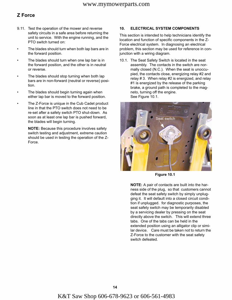
12.4. Remove the nut and socket head cap screw that hold the pivot bracket to the steering input shaft using a 1/4” Allen wrench and a 1/2” wrench. See Figure 12.4.
12.5. Slide the lap bar and pivot bracket assembly off of the steering input shaft.
NOTE: If the socket head cap screw has left a burr on the steering input shaft, de-burr the shaft before attempting to remove it.
12.6. Push the steering input shaft into the control housing far enough to allow the removal of the outside bushing.
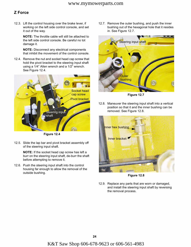
12.7. Remove the outer bushing, and push the inner bushing out of the hexagonal hole that it resides in. See Figure 12.7.
12.8. Maneuver the steering input shaft into a vertical position so that it and the inner bushing can be removed. See Figure 12.8.
12.9. Replace any parts that are worn or damaged, and install the steering input shaft by reversing the removal process.
Figure 12.4
Socket headcap screw
Pivot bracket
Steering inputshaft
Figure 12.7
Outer bushing
Steering input shaft
Figure 12.8
Inner hex bushing
Inner bracket
24
K&T Saw Shop 606-678-9623 or 606-561-4983

Z Force
www.mymowerparts.com
13. PIVOT BAR
13.1. Lift and safely support the Z-Force by the frame in front of the deck. See Figure 13.1.
13.2. Wheel removal can be done with two 3/4” wrenches. Remove the nut and withdraw the axle bolt.
13.3. There is a spacer that fits over each side of the wheel bearing, keeping the wheel centered between the caster wheel mounting bracket. See Figure 13.3.
13.4. The roller bearings in the wheel ride on the axle bushing. Other than regular lubrication with grease, the bearing is non-serviceable.
Figure 13.1
Figure 13.3
Spacer
Axle bushing
25
K&T Saw Shop 606-678-
13.5. If the pivot bar is to be removed, the foot rest bracket must be removed first, using a pair of 1/2” wrenches. See Figure 13.5.
NOTE: The deck need not be removed.
13.6. Remove at least one caster wheel assembly using a 9/16” wrench. See Figure 13.6.
Figure 13.5
Foot rest bracket
Figure 13.6
9623 or 606-561-4983
Z Force
www.mymowerparts.com
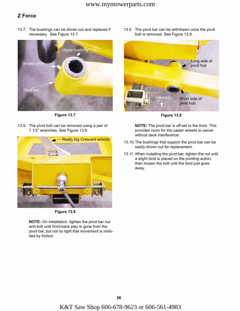
13.7. The bushings can be driven out and replaced if necessary. See Figure 13.7.
13.8. The pivot bolt can be removed using a pair of 1 1/2” wrenches. See Figure 13.8.
NOTE: On installation, tighten the pivot bar nut and bolt until front-back play is gone from the pivot bar, but not so tight that movement is inhib-ited by friction.
13.9. The pivot bar can be withdrawn once the pivot bolt is removed. See Figure 13.9.
NOTE: The pivot bar is off-set to the front. This provides room for the caster wheels to swivel without deck interference.
13.10.The bushings that support the pivot bar can be easily driven out for replacement.
13.11. When installing the pivot bar, tighten the nut until a slight bind is placed on the pivoting action, then loosen the bolt until the bind just goes away.
Figure 13.7
Grease zirch
Pivot bar
Upper bushing
Figure 13.8
Really big Crescent wrench
Figure 13.9
Forward
Long side of pivot hub
Short side of pivot hub
26
K&T Saw Shop 606-678-9623 or 606-561-4983
Z Force
www.mymowerparts.com
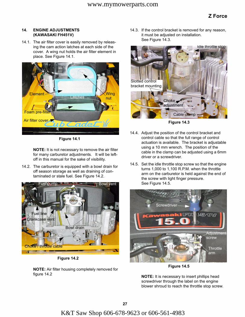
14. ENGINE ADJUSTMENTS (KAWASAKI FH451V)
14.1. The air filter cover is easily removed by releas-ing the cam action latches at each side of the cover. A wing nut holds the air filter element in place. See Figure 14.1.
NOTE: It is not necessary to remove the air filter for many carburetor adjustments. It will be left-off in this manual for the sake of visibility.
14.2. The carburetor is equipped with a bowl drain for off season storage as well as draining of con-taminated or stale fuel. See Figure 14.2.
NOTE: Air filter housing completely removed for figure 14.2
Figure 14.1
Latches
Air filter cover
Foam pre-filter
Element Wing nut
Figure 14.2
Bowl drain
Bowl ventFuel pump
Fuel lineCrankcase vent
Choke / throttle cable
27
K&T Saw Shop 606-678-
14.3. If the control bracket is removed for any reason, it must be adjusted on installation. See Figure 14.3.
14.4. Adjust the position of the control bracket and control cable so that the full range of control actuation is available. The bracket is adjustable using a 10 mm wrench. The position of the cable in the clamp can be adjusted using a 6mm driver or a screwdriver.
14.5. Set the idle throttle stop screw so that the engine turns 1,000 to 1,100 R.P.M. when the throttle arm on the carburetor is held against the end of the screw with light finger pressure. See Figure 14.5.
NOTE: It is necessary to insert phillips head screwdriver through the label on the engine blower shroud to reach the throttle stop screw.
Figure 14.3
Idle throttle stop
Chokeadjustment
Cable clamp
Slotted control bracket mounting
Figure 14.5
Screwdriver
Throttle arm
Adjustmentscrew
9623 or 606-561-4983

Z Force
www.mymowerparts.com
14.6. Set the governed idle to 1,550 R.P.M. using the screw at the lower right hand corner of the con-trol bracket. See Figure 14.6.
14.7. With the governed idle and idle throttle stop adjusted, the engine should maintain a 1,550 R.P. M. idle, but should not fall below 1,000 R.P.M. unless the engine is over-loaded.
14.8. Top no-load speed should be adjusted to within the range of 3,600 to 3,650 R.P.M. This is done by slightly bending the arm on the control bracket that pulls on the governor spring.
NOTE: If high speed governor response is slug-gish, check for interference between the gover-nor rod and the governor spring.
NOTE: If high speed performance is weak, con-firm that the choke is not closing prematurely.
14.9. Adjust the choke using the screw on the control bracket. See Figure 14.9.
14.10.With the engine turned-off, insert a 1/4” pin in the round hole when the throttle is set for top no-load speed. This will lock the linkage in that position.
14.11. Using a phillips head screwdriver inserted from behind the left corner of the control bracket, set the choke adjustment screw to leave a .199” gap between the tip of the screw and the point where it contacts the arm that actuates the choke rod.
14.12.After all carburetion adjustments are made, run the engine to double check the idle speed, throt-tle stop, top no-load speed, and unimpeded link-age movement.
NOTE: Because the Z-Force engine is not equipped with a fuel shut-off solenoid, after-boom may occur if it is turned-off at idle speed. This will cause no harm, but customers may find it objectionable. To avoid after-boom, the engine should be throttled-up slightly at the moment of shut-down. The opening of the throttle plate will reduce the vacuum level in the intake manifold, preventing the ingestion of a rich fuel air mixture from the idle jet on over-run. After the ignition (spark) is turned-off, the inertia of the engine will pump unburned fuel and air into the hot muffler. The presence of this mixture in the hot muffler is the source of after-boom.
Figure 14.6
Governed idleadjustment screw
Figure 14.8
Governorspring
Governor rod (to throttle on carburetor)
Governor arm
Adjust here
Figure 14.9
Insert 1/4” pinChoke actuator arm
.100” gap(2.7mm)
Adjustmentscrew
28
K&T Saw Shop 606-678-9623 or 606-561-4983

Z Force
www.mymowerparts.com
14.13.Turn the engine off, and confirm correct choke adjustment. Remove the air filter cover and air filter to confirm that the choke plate is fully closed when the choke is applied, and fully open at the full-throttle position. See Figure 14.13.
14.14.The valve lash should be checked after every 300 hours of use.
14.15. If the Z-Force has been run recently, allow the engine to cool before adjusting the valves.
14.16.Clean the engine and surrounding area before beginning the valve lash adjustment.
14.17.Disconnect and ground the spark plug wires.
14.18.Remove the spark plugs using a 3/4” spark plug socket.
14.19.Remove the valve covers using a 10mm wrench. See Figure 14.19.
Figure 14.13
Figure 14.19
Valve covers
29
K&T Saw Shop 606-678-
14.20.Rotate the engine in its normal direction of oper-ation until the piston in the first cylinder to be adjusted is at top dead center on the compres-sion stroke (both valves closed).
14.21.Check the valve lash. Clearance between the stem of the intake valve and the intake rocker arm should be .004” - .006” (.10mm - .15mm). Clearance between the stem of the exhaust valve and the exhaust rocker arm should also be be .004” - .006”.
14.22. If necessary, adjust the clearance using a 3mm allen wrench to loosen the locks crews, and a 14mm wrench to move the adjusting nut. See Figure 14.22.
14.23.Torque the locks crews to 61 in-lb. (6.9 N-m), and re-check adjustment.
14.24.When adjustment is complete on the first cylin-der, turn the crankshaft to bring the second pis-ton to top dead center on the compression stroke, and repeat the adjustment procedure on the second cylinder.
14.25. Install the valve covers using new valve cover gaskets. Install the screws through the valve covers before positioning them on each cylinder head. The gaskets are most easily positioned on the valve covers rather than the cylinder head. They will be held in the correct position by the screws. Sealant should not be necessary.
14.26.Torque the valve covers screws to 17 in-lb. (.20 N-m).
14.27.Check compression for consistency between cylinders. Optional: check leak-down. If more than 10% difference is found, cylinder head reconditioning may be necessary.
Figure 14.22
Locks crews
Adjusting nuts
Checklashhere
Exhaust valve
Intake valve
H.T. lead
Spark plug hole
9623 or 606-561-4983

Z Force
www.mymowerparts.com
14.28. Inspect and gap (or replace) the spark plugs prior to installation.
14.29.Spark plugs: Champion RC8Y or equivalent, gapped to .030” (.75mm).
14.30.Oil capacity: 1.6 U.S. qts. (1.5L) without filter replacement. Use 1.8 U.S. qts. (1.7L) with filter replacement.
14.31.Oil type: API Service Classification SF, SG, SH, or SJ.
14.32.Oil viscosity: SAE30 will be suitable for most operating conditions (32 deg.f. to 90 deg.f.). Where temperatures exceed 100dg. f. SAE40 is an acceptable alternative (68 deg. f. and up). If multi-grade oils are used, an increase in oil con-sumption is to be expected, and the oil must be checked more frequently.
15. THE Z-FORCE MODEL LINE-UP
15.1. There are three engine and deck combinations available on the Z-Force for 2004. See Figure 15.1.
• 42” two blade cutting deck with an 18.5 H.P. Briggs and Stratton Intek single cylinder engine
• 44” three blade cutting deck with a 20 H.P. Briggs and Stratton Intek V-twin engine
• 48” three blade cutting deck with a 22 H.P. Brigs and Stratton Intek V-twin engine.
15.2. We have chosen to cover some service informa-tion that applies to the Kawasaki engine offered the 2003 Z-Force because it is likely to be less familiar to technicians than the Briggs and Strat-ton products.
15.3. The cutting decks are all similar to those offer elsewhere in the Cub Cadet model line, with the exception of the mounting method and drive ori-entation (front Vs. rear engine). See Figure 15.3.
Figure 15.1
Figure 15.3
30
K&T Saw Shop 606-678-9623 or 606-561-4983