Embed Size (px)
Citation preview

Eaton® DuraForce™ HMF
Service Manual

2 EATON Duraforce HMF Service Manual E-MOPI-TS010-E July 2012
Content Page #
Table of Contents
Priority Swing Motor Regulation Begin Adjustment Procedure
Set Up 3
Procedure 4
VD20-05 Externally Adjustable Relief Valve Adjustment Procedure
Set Up 5
Procedure for the "High" Setting 6
Procedure for the "Low" Setting 6
Procedure for the Deceleration Slope Position 7
Priority Swing Motor Torque Curve and Max Torque Adjustment Procedure
Set Up 8
Procedure for the Torque Curve Position 9
Procedure for the Maximum Torque Value 10
Priority Swing Motor Flow Stop Adjustment Procedure
Set Up & Procedure 11
Procedure to Adjust Single Setting Cross-Over Relief Valves on HMR Motors
Set Up & Procedure 12
Procedure to Adjust VD20-03 Dual-Stage Relief Valves
High Pressure Adjustment Procedure 13
Low Pressure Adjustment Procedure 14
Environmental Concerns
Protection of the natural fundamentals of life is one of our predominant tasks. We are continuously improving the protection of the environment as far as applications are concerned. We encourage you to contribute your share to comply with this demand. In connection with work to be performed, the environmental regulations of the machine manufacturer must be respected.
In general:
• Greases and oils which cannot be used any more have to be collected. They are normally a threat to water reserves and must be kept away from the environment.
• Adhere to national and local regulations for waste disposal.
Important
You have been provided information on the conversion of DuraForce products. Proper application of the information requires specific training and may require use of specialized tooling and equipment. All requests for training must be coordinated through your Eaton Account Manager. He can also provide you price and availability of any specialized tooling. If you choose to proceed with the conversion of the DuraForce products absent the necessary training and/or these specialized tools, you do so at your risk.
Eaton will accept no claim for warranty resulting from deficiencies in the conversion. Please refer to the Eaton literature web site for warranty information at www.eaton.com/hydraulics/warranty.

3EATON Duraforce HMF Service Manual E-MOPI-TS010-E July 2012
Priority Swing Motor Regulation Begin Adjustment ProcedureSet Up
Tools / Equipment Required
• 5mm Allen wrench (HMF55 Motors ONLY)
• 6mm Allen wrench (HMF75 and HMF105 Motors ONLY)
• 0-500 psi Dp-gauge (Optional: Two, 0-600 psi pressure gauges or transducers)
For HMF55 Motors:
• P/N 000.914.5495, 0.8mm shim (as required)
• P/N 000.914.5496, 1.0mm shim (as required)
• P/N 000.914.5497, 1.4mm shim (as required)
For HMF75 and HMF105 Motors:
• P/N 9289.003.470, 0.1mm shim (as required)
• P/N 9289.003.472, 0.3mm shim (as required)
• P/N 9289.003.473, 0.5mm shim (as required)
• P/N 000.914.5492, 0.8mm shim (as required)
• P/N 000.914.5493, 1.0mm shim (as required)
• P/N 000.914.5494, 1.4mm shim (as required)
Note
When setting up or adjusting the HMF Priority Swing Motor, follow the instructions in this service manual in sequential order.
WARNING
If performing this procedure on a vehicle, care must be taken. The pump will be put on stroke during this procedure, hence all personnel should be removed from the area of the machine.
Reference Data
For HMF Priority Swing Motors containing "standard" Spool Centering Springs, the following spring-rate data can be used as a reference to help you determine the thickness of shims needed to increase or decrease the regulation begin pressure to the desired setting:
• (For HMF55 Motors) 26 psi/mm
• (For HMF75 and HMF105 Motors) 22 psi/mm
For those motors NOT containing "standard" Spool Centering Springs, please consult EatonEngineering to see if data is available.

4 EATON Duraforce HMF Service Manual E-MOPI-TS010-E July 2012
Priority Swing Motor Regulation Begin Adjustment ProcedureAdjustment Procedure
WARNING
If performing this procedure on a vehicle, care must be taken. The pump will be put on stroke during this procedure, hence all personnel should be removed from the area of the machine.
1. Connect the "HI" side of the Dp-gauge to Port "X".
2. Connect the "LO" side of the Dp-gauge to Port "Y".
3. Slowly supply pilot pressure into Port "X". Simulataneously monitor the Dp-gauge and the function the HMF motor is actuating.
4. Record the pressure on the Dp-gauge when the function just starts to move. This is the regulation begin pressure for Workport "A".
5. To adjust the regulation begin pressure:
a. Remove the End Cap on the opposite side of Workport "A" (the end cap containing the "B" Side Shims) by removing the two socket-head cap screws (SHCS).
b. Make sure that the O-Ring remains in the end cap o-ring groove.
c. Remove the Spool Cap and the Spool Centering Spring from the end cap.
d. As required, ADD shims to the end cap to increase the regulation begin pressure or REMOVE shims to decrease the regulation begin pressure.
e. Reinstall all of the parts removed in steps b and c. Make sure that the O-Ring is properly installed into the end cap o-ring groove to avoid damaging it.
f. Reinstall the two SHCS from step a. The proper torque for each SHCS is:
- (For HMF55 Motors)…………………………..9.5 N-m (7 ft-lb)
- (For HMF75 and HMF105 Motors)………25 N-m (18 ft-lb)
g. Repeat steps #3 and #4 to verify that the desired regulation begin pressure has been acquired.
6. Connect the "HI" side of the Dp-gauge to Port "Y".
7. Connect the "LO" side of the Dp-gauge to Port "X".
8. Slowly supply pilot pressure into Port "Y". Simulataneously monitor the Dp-gauge and the function the HMF motor is actuating.
9. Record the pressure on the Dp-gauge when the function just starts to move. This is the regulation begin pressure for Workport "B".
10. To adjust the regulation begin pressure:
a. Remove the End Cap on the opposite side of Workport "B" (the end cap containing the "A" Side Shims) by removing the two socket-head cap screws (SHCS).
b. Make sure that the O-Ring remains in the end cap o-ring groove.
c. Remove the Spool Cap and the Spool Centering Spring from the end cap.
d. As required, ADD shims to the end cap to increase the regulation begin pressure or REMOVE shims to decrease the regulation begin pressure.
e. Reinstall all of the parts removed in steps b and c. Make sure that the O-Ring is properly installed into the end cap o-ring groove to avoid damaging it.
f. Reinstall the two SHCS from step a. The proper torque for each SHCS is:
- (For HMF55 Motors)…………………………..9.5 N-m (7 ft-lb)
- (For HMF75 and HMF105 Motors)………25 N-m (18 ft-lb)
g. Repeat steps #8 and #9 to verify that the desired regulation begin pressure has been acquired.
11. Remove the Dp-gauge from the motor.
Adjustment Procedure for the Motor Regulation Begin Pressure:
Note
Reference the section above titled "Tools/Equipment Required" for the part numbers corresponding to the HMF motor you are working with. Please note that each size motor has multiple shim thicknesses available.
Note
When setting up or adjusting the HMF Priority Swing Motor, follow the instructions in this service manual in sequential order.

5EATON Duraforce HMF Service Manual E-MOPI-TS010-E July 2012
VD20-05 Externally Adjustable Relief Valve Adjustment ProcedureSet Up
Tools / Equipment Required
• 36mm wrench
• 30mm wrench
• 10mm closed-end, offset wrench
• 10mm open-end wrench (Optional: small adjustable wrench)
• 3mm Allen wrench
• 0-7000 psi pressure gauge (Optional: 0-7000 psi pressure transducer)
Important
All supplemental relief valves used in the same circuit as the VD20-05 relief valves must be set higher than the desired settings for the VD20-05 relief valves. This must be done prior to performing the steps in this Service Bulletin.
WARNING
If performing this procedure on a vehicle, care must be taken. The pump will be put on stroke during this procedure, hence all personnel should be removed from the area of the machine.
In order to successfully measure and adjust the VD20-05 relief valve settings, the maximum torque pressure must be set higher than the desired "High" setting for the VD20-05. The adjustment to the maximum torque pressure must be done prior to using this
Service Bulletin. To do so, perform the following steps:
1. On the Maximum Torque Adjustment Valve, hold the Adjustment Screw stationary with a 10mm wrench, and loosen the Locking Nut with the other 10mm wrench.
2. Turn the Adjustment Screw IN fully until it can no longer be turned in.
3. While holding the Adjustment Screw stationary, tighten the Locking Nut.
Upon completion of this Service Bulletin, you must properly readjust the Maximum Torque Adjustment Valve. To do this, refer to page 10 for instructions on how to do this.
pilot pressure
wor
kpo r
t pre
ssur
e
Maximum TorquePressure
Torque Curve"Low"Setting
"High" Setting
The position of the deceleration slope can be moved upward ordownward, as illustrated here. Only the position of the slopecan be changed, NOT the angle of the slope.
Important

6 EATON Duraforce HMF Service Manual E-MOPI-TS010-E July 2012
VD20-05 Externally Adjustable Relief Valve Adjustment ProcedureAdjustment Procedure
WARNING
If performing this procedure on a vehicle, care must be taken. The pump will be put on stroke during this procedure, hence all personnel should be removed from the area of the machine.
1. Install the pressure gauge to measure pressure at Port "LS". If this is not possible, install the pressure gauge at the most accessible location to measure load sense pressure.
2. For this adjustment, the function that the motor actuates must be locked as to prevent the motor from rotating. This will force the motor to the maximum pressure when actuated.
3. Supply full pilot pressure into Port "X".
4. Read the pressure on the gauge - This is the "High" Setting of the VD20-05.
5. To adjust the "High" Setting:
a. Refer to the illustration on page 5 of this Service Bulletin to insure that you are making adjustments to the correct VD20-05.
b. Hold the Adjustment for "High" Setting stationary with the 30mm wrench, and loosen the Locking Nut for "High" Setting with the 36mm wrench.
c. Turn the Adjustment for "High" Setting IN to increase the pressure setting or OUT to decrease the pressure setting.
d. Once the desired pressure setting has been acquired, hold the Adjustment for "High" Setting stationary and tighten the Locking Nut for "High" Setting.
6. Supply full pilot pressure into Port "Y".
7. Read the pressure on the gauge - This is the "High" Setting of the other VD20-05.
8. To adjust the "High" Setting, follow step #5 above.
Adjustment Procedure for the "High" Setting on the VD20-05:
1. Install the pressure gauge to measure pressure at Port "LS". If this is not possible, install the pressure gauge at the most accessible location to measure load sense pressure.
2. As described in the note to the left, supply full pilot pressure into Port "X" to fully actuate the motor, then allow the function to coast to a stop. As the function is coasting to a stop, read the pressure on the gauge - This is the "Low" Setting of the VD20-05.
3. To adjust the "Low" Setting:
a. Refer to the illustration on page 5 of this Service Bulletin to insure that you are making adjustments to the correct VD20-05.
b. Hold the Adjustment for "Low" Setting stationary with the 22mm-wide flat screwdriver, and loosen the Locking Nut for "Low" Setting with the 30mm wrench.
c. Turn the Adjustment for "Low" Setting IN to increase the pressure setting or OUT to decrease the pressure setting.
d. Once the desired pressure setting has been acquired, hold the Adjustment for "Low" Setting stationary and tighten the Locking Nut for "Low" Setting.
4. As described in the note to the left, supply full pilot pressure into Port "Y" to fully actuate the motor, then allow the function to coast to a stop. As the function is coasting to a stop, read the pressure on the gauge - This is the "Low" Setting of the other VD20-05.
5. To adjust the "Low" Setting, follow step #3 above.
Adjustment Procedure for the "Low" Setting on the VD20-05:
Note
To measure and adjust the "Low" Setting, there cannot be any pilot pressure in either Port "X" or Port "Y". Therefore, the function that the motor is actuating must be fully actuated to maximum speed. Once at maximum speed, the pilot pressure must be removed completely and the function must coast to a stop. As the function coasts to a stop, oil is passing over the VD20-05 relief valve. It is under this condition that the VD20-05 relief valve is at the "Low" Setting and a pressure measurement can be made.

7EATON Duraforce HMF Service Manual E-MOPI-TS010-E July 2012
Note
The HMF Priority Swing Motor is only equipped with the VD20-05 dual-stage relief valves. For those who only need or want a single setting relief valve for this motor, you must still use the VD20-05 relief valves. To get the function of a single setting relief valve, adjust the "High" Setting to the desired relief valve pressure. Then do the following for both VD20-05 relief valves:
1. Hold the Adjustment for "Low" Setting stationary with the 22mm-wide flat screwdriver, and loosen the Locking Nut for "Low" Setting with the 30mm wrench.
2. Turn the Adjustment for "Low" Setting IN fully until it can no longer be turned in.
3. Hold the Adjustment for "Low" Setting stationary and tighten the Locking Nut for "Low" Setting.
VD20-05 Externally Adjustable Relief Valve Adjustment ProcedureAdjustment Procedure
WARNING
If performing this procedure on a vehicle, care must be taken. The pump will be put on stroke during this procedure, hence all personnel should be removed from the area of the machine.
Note
The deceleration slope feature of the VD20-05 provides the operator with a feel of smooth, controllable deceleration. The deceleration force is proportional to the pilot pressure supplied into either Port "X” or Port "Y" by the operator. By removing the pilot pressure, the VD20-05 defaults to the "Low" Setting. If the operator changes the pilot pressure from full to none, the VD20-05 switches from the "High" Setting to the "Low" Setting and by-passes the deceleration slope. The position of the deceleration slope depends solely on how the operator wants the motor to decelerate.
To make the deceleration more controllable, the position of the deceleration slope should be moved downward. To make the deceleration less controllable, the position of the deceleration slope should be moved upward. Again, the final deceleration slope position should be adjusted to satisfy the operator's feel for deceleration.
1. Have the operator run the motor. If the motor deceleration is satisfactory, then disregard the rest of this Service Bulletin. Otherwise, continue to the next step.
2. To adjust the position of the deceleration slope:
a. Hold the Adjustment Stud for Deceleration Slope Position stationary with the 3mm Allen wrench, and loosen the Locking Nut for Deceleration Slope Position with the 10mm closed-end, offset wrench.
b. Turn the Adjustment Stud IN to move the deceleration slope upward or turn it OUT to move the deceleration slope downward.
c. Once the desired deceleration is acquired, hold the Adjustment Stud stationary and tighten the Locking Nut.
Note
If you do not want or need the deceleration slope feature of the VD20-05 relief valves, then it can be disabled. By doing this, however, the VD20-05 will only function at two distinct pressures - The "High" Setting and the "Low" Setting. To disable the deceleration slope, do the following:
1. Hold the Adjustment Stud for Deceleration Slope Position stationary with the 3mm Allen wrench, and loosen the Locking Nut for Deceleration Slope Position with the 10mm closed-end, offset wrench.
2. Turn the Adjustment Stud IN fully until it can no longer be turned in.
3. Hold the Adjustment Stud stationary and tighten the Locking Nut.
Adjustment Procedure for the Deceleration Slope Position on the VD20-05:

8 EATON Duraforce HMF Service Manual E-MOPI-TS010-E July 2012
Priority Swing Motor Torque Curve and Max Torque Adjustment ProcedureSet Up
Tools / Equipment Required
• 10mm Wrench
• 3mm Allen Wrench
• 0-7000 psi pressure gauge or transducer
• 0-300 psi pressure gauge or transducer
WARNING
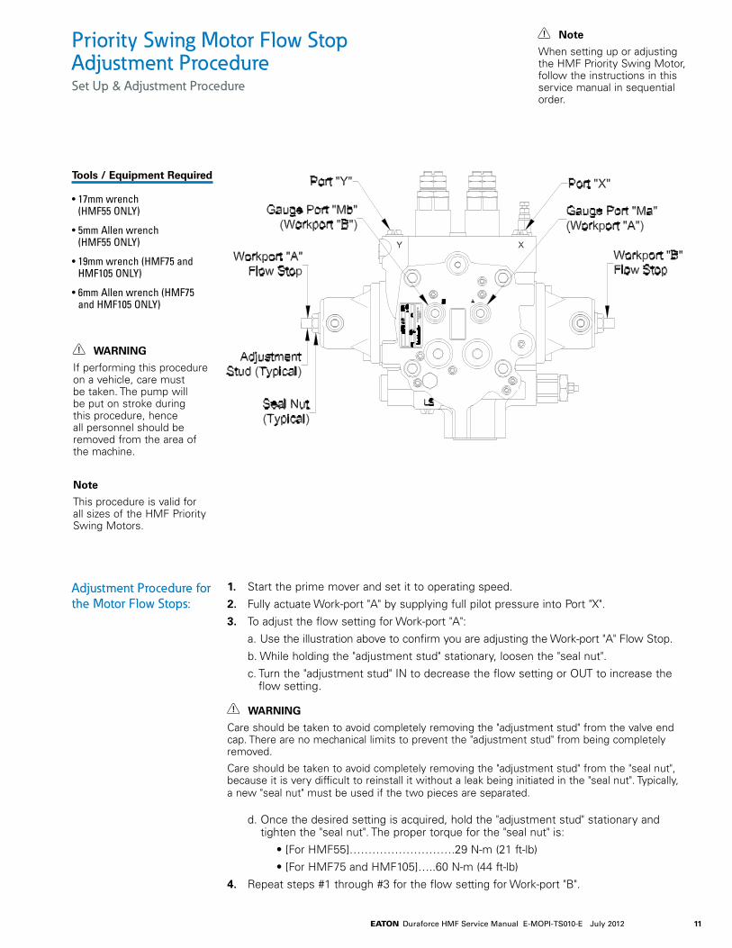
If performing this procedure on a vehicle, care must be taken. The pump will be put on stroke during this procedure, hence all personnel should be removed from the area of the machine. “IS” Port
Torque-Curve PositionAdjustment Valve
Locking Nut
AdjustmentStud
“MST” Port
Gauge Port “Ma”Workport “A”
Port “X”
Locking Nut
Adjustment Screwfor Maximum Torque
XY
9EATON Duraforce HMF Service Manual E-MOPI-TS010-E July 2012
Priority Swing Motor Torque Curve and Max Torque Adjustment ProcedureAdjustment Procedure
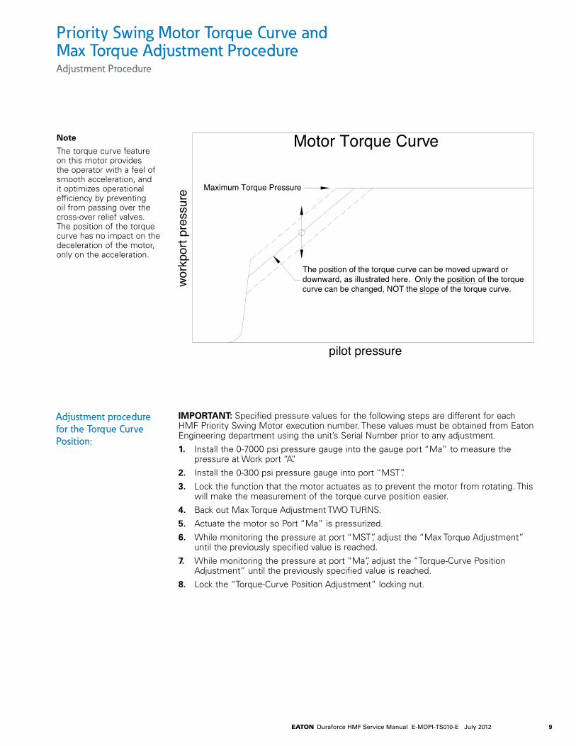
IMPORTANT: Specified pressure values for the following steps are different for each HMF Priority Swing Motor execution number. These values must be obtained from Eaton Engineering department using the unit’s Serial Number prior to any adjustment.
1. Install the 0-7000 psi pressure gauge into the gauge port “Ma” to measure the pressure at Work port “A”.
2. Install the 0-300 psi pressure gauge into port “MST”.
3. Lock the function that the motor actuates as to prevent the motor from rotating. This will make the measurement of the torque curve position easier.
4. Back out Max Torque Adjustment TWO TURNS.
5. Actuate the motor so Port “Ma” is pressurized.
6. While monitoring the pressure at port “MST”, adjust the “Max Torque Adjustment” until the previously specified value is reached.
7. While monitoring the pressure at port “Ma”, adjust the “Torque-Curve Position Adjustment” until the previously specified value is reached.
8. Lock the “Torque-Curve Position Adjustment” locking nut.
Adjustment procedure for the Torque Curve Position:
pilot pressure
wor
kpor
t pre
ssur
e
Motor Torque Curve
Maximum Torque Pressure
The position of the torque curve can be moved upward ordownward, as illustrated here. Only the position of the torquecurve can be changed, NOT the slope of the torque curve.
Note
The torque curve feature on this motor provides the operator with a feel of smooth acceleration, and it optimizes operational efficiency by preventing oil from passing over the cross-over relief valves. The position of the torque curve has no impact on the deceleration of the motor, only on the acceleration.

10 EATON Duraforce HMF Service Manual E-MOPI-TS010-E July 2012
Priority Swing Motor Torque Curve and Max Torque Adjustment ProcedureAdjustment Procedure
IMPORTANT: In order to successfully measure and adjust the maximum torque setting on the HMF Priority Swing Motor, the “high setting” cracking pressure on the two dual-stage cross-over relief valves must be set at or higher than the desired maximum torque setting for the motor. This adjustment to the dual-stage cross-over relief valve must be done prior to using this Service Bulletin.
1. Lock the function that the motor actuates as to prevent the motor from rotating
2. Actuate the motor so port “Ma” is pressurized.
3. While monitoring the pressure at port “Ma”, adjust the “Max Torque Adjustment” until the previously specified Maximum Torque value is reached.
4. Lock the “Max. Torque Adjustment” locking nut.
Adjustment procedure for the Maximum Torque Value:
pilot pressure
wor
kpo r
t pre
ssur
e
Motor Torque Curve
Maximum Torque Pressure
The Maximum Torque Pressure can beincreased or decreased as illustrated above
by following the instructions in this Service Bulletin
11EATON Duraforce HMF Service Manual E-MOPI-TS010-E July 2012
Priority Swing Motor Flow Stop Adjustment ProcedureSet Up & Adjustment Procedure
Tools / Equipment Required
• 17mm wrench (HMF55 ONLY)
• 5mm Allen wrench (HMF55 ONLY)
• 19mm wrench (HMF75 and HMF105 ONLY)
• 6mm Allen wrench (HMF75 and HMF105 ONLY)
WARNING
If performing this procedure on a vehicle, care must be taken. The pump will be put on stroke during this procedure, hence all personnel should be removed from the area of the machine.
Note
This procedure is valid for all sizes of the HMF Priority Swing Motors.
Note
When setting up or adjusting the HMF Priority Swing Motor, follow the instructions in this service manual in sequential order.
Adjustment Procedure for the Motor Flow Stops:
1. Start the prime mover and set it to operating speed.
2. Fully actuate Work-port "A" by supplying full pilot pressure into Port "X".
3. To adjust the flow setting for Work-port "A":
a. Use the illustration above to confirm you are adjusting the Work-port "A" Flow Stop.
b. While holding the "adjustment stud" stationary, loosen the "seal nut".
c. Turn the "adjustment stud" IN to decrease the flow setting or OUT to increase the flow setting.
WARNING
Care should be taken to avoid completely removing the "adjustment stud" from the valve end cap. There are no mechanical limits to prevent the "adjustment stud" from being completely removed.
Care should be taken to avoid completely removing the "adjustment stud" from the "seal nut", because it is very difficult to reinstall it without a leak being initiated in the "seal nut". Typically, a new "seal nut" must be used if the two pieces are separated.
d. Once the desired setting is acquired, hold the "adjustment stud" stationary and tighten the "seal nut". The proper torque for the "seal nut" is:
• [For HMF55]……………………….29 N-m (21 ft-lb)
• [For HMF75 and HMF105]…..60 N-m (44 ft-lb)
4. Repeat steps #1 through #3 for the flow setting for Work-port "B".

12 EATON Duraforce HMF Service Manual E-MOPI-TS010-E July 2012
Procedure to Adjust Single Setting Cross-Over Relief Valves on HMF MotorSet Up & Procedure
IMPORTANT: All supplemental relief valves used in the same circuit as the VD20-04 Single-Setting Relief Valves must be set higher than the desired setting for the VD20-04 relief valves. This must be done prior to performing the steps in this Service Bulletin.
1. Install the pressure gauge or transducer to measure the pressure at Work-port "A". The function that the HMF motor actuates must be locked as to prevent the HMF motor from rotating. This will force oil to pass over the relief valve once oil is supplied to the HMF motor.
2. Supply flow to Work-port "A". Only supply the maximum flow that the motor will receive during normal operation.
IMPORTANT: When pushing oil past the relief valve as described in step #2, the hydraulic oil and relief valve will heat up rapidly. Therefore, limit the timing in step #2 to 30 seconds or less. You should monitor the temperature of the hydraulic oil and HMF motor to ensure that they do NOT exceed 194°F (90°C). If the temperature of either reaches this maximum limit, stop all testing until the temperature cools off.
3. While supplying flow to Work-port "A", read the pressure on the gauge - This is the setting for the Work-port "A" Relief Valve.
4. To adjust the Work-port "A" Relief Valve pressure setting:
a. Refer to the illustration above to make sure you are working on the correct relief valve.
b. Hold the Adjustment Stud stationary with the 5mm Allen wrench, and loosen the Seal Nut with the 17mm wrench.
c. Turn the Adjustment Stud IN to increase the relief valve pressure setting or OUT to decrease the relief valve pressure setting.
d. Once the desired pressure setting has been acquired, hold the Adjustment Stud stationary and tighten the Seal Nut. The proper torque for the Seal Nut is 60 N-m (44 ft-lb).
5. Repeat steps #1 through #4 for Work-port "B".
Procedure to Adjust Single Setting Cross-Over Relief Valves on HMF Motor
Tools / Equipment Required
• 5mm Allen wrench
• 17mm wrench
• 0-7000 psi pressure gauge or transducer

13EATON Duraforce HMF Service Manual E-MOPI-TS010-E July 2012
Procedure to Adjust the VD20-03 Dual-Stage Relief ValvesProcedure
1. Supply 80 psi to 435 psi into the pilot port at the end of the relief valve. This will shift the relief valve to the high-pressure setting.
2. Actuate the function and record the motor workport pressure (Note: Motor must be loaded enough to open the relief valve). This is the high-pressure setting on the VD20-03 relief valve. To adjust:
a. Remove the relief valve from the motor.
b. Disassemble the relief valve to gain access to “SHIMS PSCH 1”:
• remove the “End Cap”
• remove the “Plunger”
• remove “SPRING DF 1”
c. Add shims to increase the relief valve setting or remove to decrease.
(a) (HINT: 0.1mm shim = 340 psi change)
• shim part number 9289003019 = 0.25mm
• shim part number 9289003017 = 0.10mm
d. Reassemble the relief valve:
• reinstall the “Plunger” making sure to capture all springs and shims
• reinstall the “End Cap” and torque it to 59 ft-lb, making sure that the o-ring is properly positioned
• reinstall the relief valve into the motor and torque it to 59 ft-lb
3. Repeat steps #1 and #2 until the desired high-pressure setting is acquired.
High Pressure Adjustment Procedure
Note
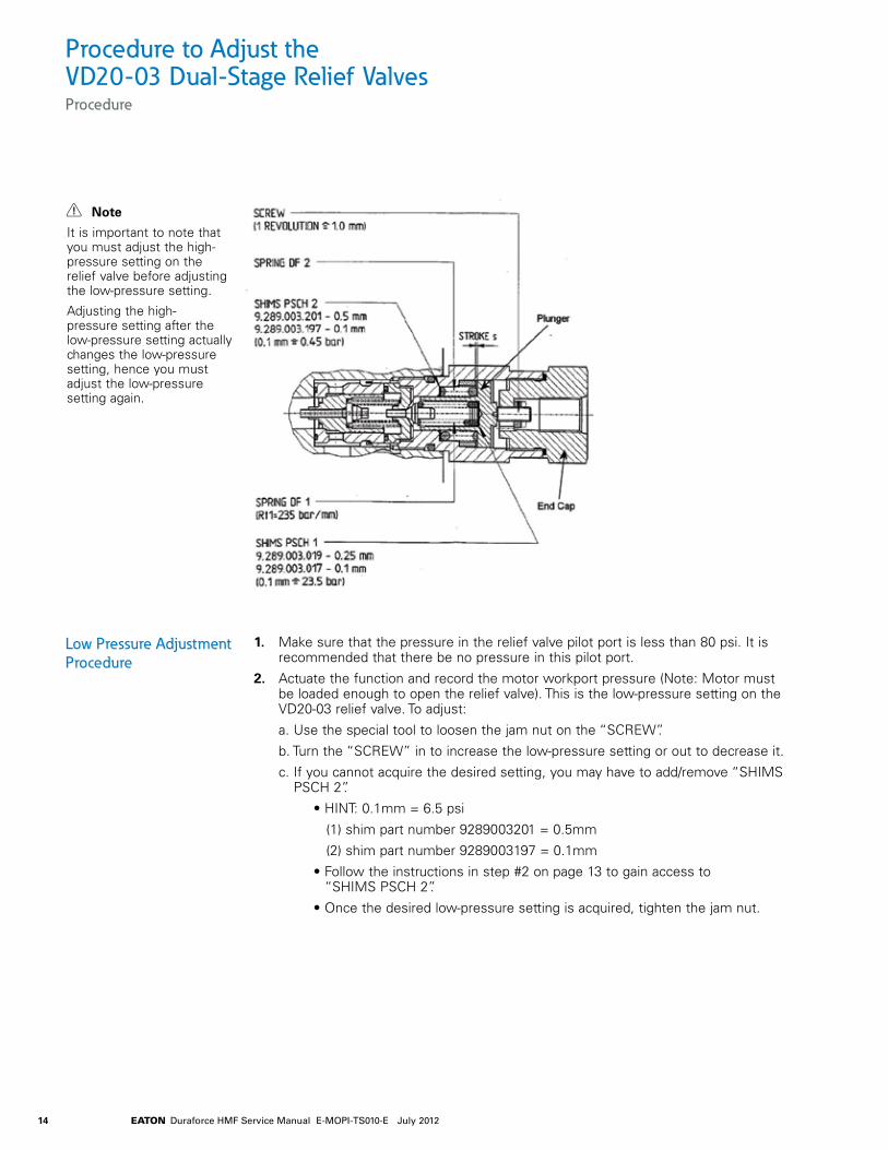
It is important to note that you must adjust the high-pressure setting on the relief valve before adjusting the low-pressure setting.
Adjusting the high-pressure setting after the low-pressure setting actually changes the low-pressure setting, hence you must adjust the low-pressure setting again.
14 EATON Duraforce HMF Service Manual E-MOPI-TS010-E July 2012
1. Make sure that the pressure in the relief valve pilot port is less than 80 psi. It is recommended that there be no pressure in this pilot port.
2. Actuate the function and record the motor workport pressure (Note: Motor must be loaded enough to open the relief valve). This is the low-pressure setting on the VD20-03 relief valve. To adjust:
a. Use the special tool to loosen the jam nut on the “SCREW”.
b. Turn the “SCREW” in to increase the low-pressure setting or out to decrease it.
c. If you cannot acquire the desired setting, you may have to add/remove “SHIMS PSCH 2”.
• HINT: 0.1mm = 6.5 psi
(1) shim part number 9289003201 = 0.5mm
(2) shim part number 9289003197 = 0.1mm
• Follow the instructions in step #2 on page 13 to gain access to “SHIMS PSCH 2”.
• Once the desired low-pressure setting is acquired, tighten the jam nut.
Low Pressure Adjustment Procedure
Note
It is important to note that you must adjust the high-pressure setting on the relief valve before adjusting the low-pressure setting.
Adjusting the high-pressure setting after the low-pressure setting actually changes the low-pressure setting, hence you must adjust the low-pressure setting again.
Procedure to Adjust the VD20-03 Dual-Stage Relief ValvesProcedure

15EATON Duraforce HMF Service Manual E-MOPI-TS010-E July 2012

EatonHydraulics Group USA14615 Lone Oak RoadEden Prairie, MN 55344USATel: 952-937-9800Fax: 952-294-7722www.eaton.com/hydraulics
EatonHydraulics Group EuropeRoute de la Longeraie 71110 MorgesSwitzerlandTel: +41 (0) 21 811 4600Fax: +41 (0) 21 811 4601
Eaton Hydraulics Group Asia PacificEaton BuildingNo.7 Lane 280 Linhong Road Changning District, Shanghai200335 ChinaTel: (+86 21) 5200 0099Fax: (+86 21) 2230 72400
© 2012 Eaton CorporationAll Rights Reserved Printed in USADocument No. E-MOPI-TS010-EJuly 2012