Embed Size (px)
Citation preview
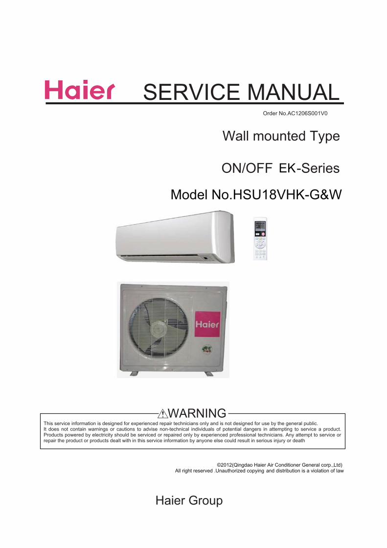
SERVICE MANUALOrder No.
ON/OFF -SeriesEK
Haier Group
This service information is designed for experienced repair technicians only and is not designed for use by the general public.It does not contain warnings or cautions to advise non-technical individuals of potential dangers in attempting to service a product.Products powered by electricity should be serviced or repaired only by experienced professional technicians. Any attempt to service orrepair the product or products dealt with in this service information by anyone else could result in serious injury or death
WARNING
Wall mounted Type
©2012(Qingdao Haier Air Conditioner General corp.,Ltd)All right reserved .Unauthorized copying and distribution is a violation of law
Model No.HSU18VHK-G&W
Table of Contents
1.Features...................................................................................................... 1
2.Introduction ................................................................................................ 2
3.Specifications ............................................................................................. 7
4.Printed circuit board connector wiring diagram ..................................... 9
5.Functions and control .............................................................................. 10
5.1 Main functions and control specification .................................................. 10
5.2 Value of thermistor ................................................................................... 15
6. System configuration ............................................................................... 23
6.1 System configuration ................................................................................ 23
6.2 Instruction ................................................................................................. 24
7. Service diagnosis .................................................................................... 31
7.1 Caution for diagnosis ................................................................................ 31
7.2 Problem symptoms and measures ........................................................... 32
8. Capacity diagrams and curves diagrams ............................................... 34
9. Installations ............................................................................................... 39
10.Wiring Diagrams ....................................................................................... 43
Domestic Air Conditioner
Features
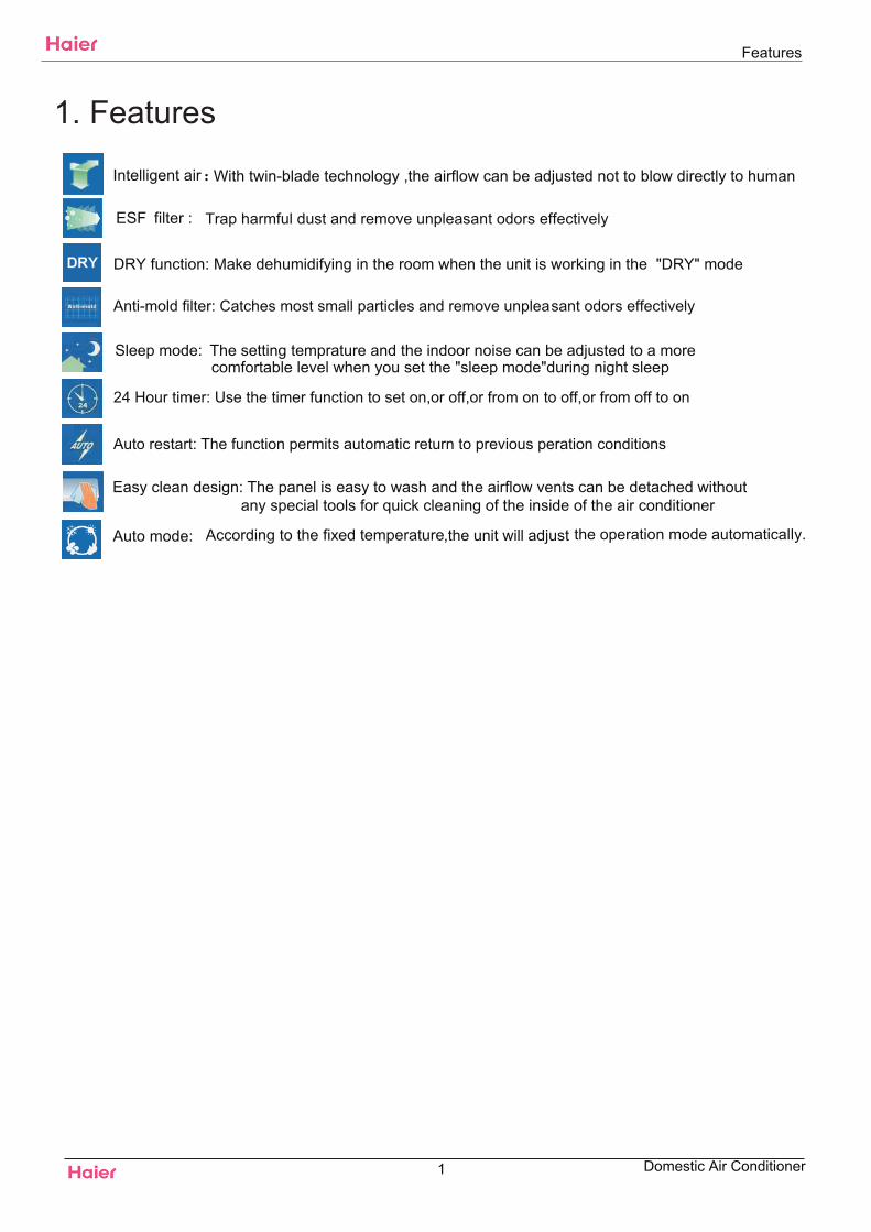
1. Features
DRY function: Make dehumidifying in the room when the unit is working in the "DRY" mode
24 Hour timer: Use the timer function to set on,or off,or from on to off,or from off to on
Auto restart: The function permits automatic return to previous peration conditions
Easy clean design: The panel is easy to wash and the airflow vents can be detached withoutany special tools for quick cleaning of the inside of the air conditioner
Anti-mold filter: Catches most small particles and remove unpleasant odors effectively
Sleep mode: The setting temprature and the indoor noise can be adjusted to a morecomfortable level when you set the "sleep mode"during night sleep
ESF filter : Trap harmful dust and remove unpleasant odors effectively
Auto mode: According to the fixed temperature,the unit will adjust the operation mode automatically.
Intelligent air With twin-blade technology ,the airflow can be adjusted not to blow directly to human
1 Domestic Air Conditioner
2. Introduction2.1 Safety Cautions
Be sure to read the following safety cautions before conducting repair work.The caution items are classified into “Warning” and “Caution”. The “Warning” items are especially importantsince they can lead to death or serious injury if they are not followed closely. The “Caution” items can also leadto serious accidents under some conditions if they are not followed. Therefore, be sure to observe all the safetycaution items described below.About the pictograms
This symbol indicates an item for which caution must be exercised.The pictogram shows the item to which attention must be paid.This symbol indicates a prohibited action.The prohibited item or action is shown inside or near the symbol.
This symbol indicates an action that must be taken, or an instruction.The instruction is shown inside or near the symbol.
After the repair work is complete, be sure to conduct a test operation to ensure that the equipment operatesnormally, and explain the cautions for operating the product to the customer.
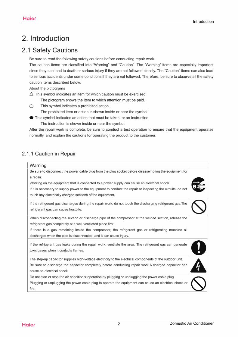
2.1.1 Caution in Repair
WarningBe sure to disconnect the power cable plug from the plug socket before disassembling the equipment for
a repair.
Working on the equipment that is connected to a power supply can cause an electrical shook.
If it is necessary to supply power to the equipment to conduct the repair or inspecting the circuits, do not
touch any electrically charged sections of the equipment.
If the refrigerant gas discharges during the repair work, do not touch the discharging refrigerant gas.The
refrigerant gas can cause frostbite.
When disconnecting the suction or discharge pipe of the compressor at the welded section, release the
refrigerant gas completely at a well-ventilated place first.
If there is a gas remaining inside the compressor, the refrigerant gas or refrigerating machine oil
discharges when the pipe is disconnected, and it can cause injury.
If the refrigerant gas leaks during the repair work, ventilate the area. The refrigerant gas can generate
toxic gases when it contacts flames.
The step-up capacitor supplies high-voltage electricity to the electrical components of the outdoor unit.
Be sure to discharge the capacitor completely before conducting repair work.A charged capacitor can
cause an electrical shock.
Do not start or stop the air conditioner operation by plugging or unplugging the power cable plug.
Plugging or unplugging the power cable plug to operate the equipment can cause an electrical shock or
fire.
2 Domestic Air Conditioner
Introduction
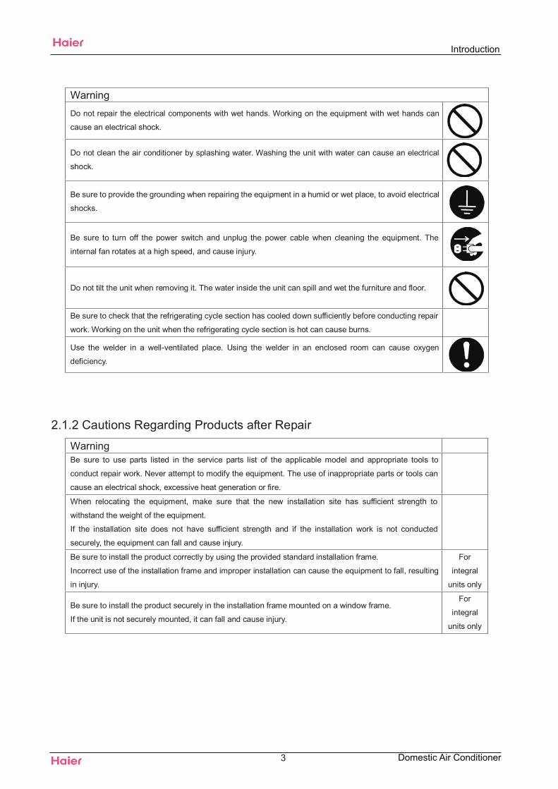
WarningDo not repair the electrical components with wet hands. Working on the equipment with wet hands can
cause an electrical shock.
Do not clean the air conditioner by splashing water. Washing the unit with water can cause an electrical
shock.
Be sure to provide the grounding when repairing the equipment in a humid or wet place, to avoid electrical
shocks.
Be sure to turn off the power switch and unplug the power cable when cleaning the equipment. The
internal fan rotates at a high speed, and cause injury.
Do not tilt the unit when removing it. The water inside the unit can spill and wet the furniture and floor.
Be sure to check that the refrigerating cycle section has cooled down sufficiently before conducting repair
work. Working on the unit when the refrigerating cycle section is hot can cause burns.
Use the welder in a well-ventilated place. Using the welder in an enclosed room can cause oxygen
deficiency.
2.1.2 Cautions Regarding Products after Repair
WarningBe sure to use parts listed in the service parts list of the applicable model and appropriate tools to
conduct repair work. Never attempt to modify the equipment. The use of inappropriate parts or tools can
cause an electrical shock, excessive heat generation or fire.
When relocating the equipment, make sure that the new installation site has sufficient strength to
withstand the weight of the equipment.
If the installation site does not have sufficient strength and if the installation work is not conducted
securely, the equipment can fall and cause injury.
Be sure to install the product correctly by using the provided standard installation frame.
Incorrect use of the installation frame and improper installation can cause the equipment to fall, resulting
in injury.
For
integral
units only
Be sure to install the product securely in the installation frame mounted on a window frame.
If the unit is not securely mounted, it can fall and cause injury.
For
integral
units only
3
Introduction
Domestic Air Conditioner
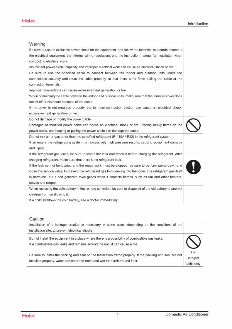
WarningBe sure to use an exclusive power circuit for the equipment, and follow the technical standards related to
the electrical equipment, the internal wiring regulations and the instruction manual for installation when
conducting electrical work.
Insufficient power circuit capacity and improper electrical work can cause an electrical shock or fire.
Be sure to use the specified cable to connect between the indoor and outdoor units. Make the
connections securely and route the cable properly so that there is no force pulling the cable at the
connection terminals.
Improper connections can cause excessive heat generation or fire.
When connecting the cable between the indoor and outdoor units, make sure that the terminal cover does
not lift off or dismount because of the cable.
If the cover is not mounted properly, the terminal connection section can cause an electrical shock,
excessive heat generation or fire.
Do not damage or modify the power cable.
Damaged or modified power cable can cause an electrical shock or fire. Placing heavy items on the
power cable, and heating or pulling the power cable can damage the cable.
Do not mix air or gas other than the specified refrigerant (R-410A / R22) in the refrigerant system.
If air enters the refrigerating system, an excessively high pressure results, causing equipment damage
and injury.
If the refrigerant gas leaks, be sure to locate the leak and repair it before charging the refrigerant. After
charging refrigerant, make sure that there is no refrigerant leak.
If the leak cannot be located and the repair work must be stopped, be sure to perform pump-down and
close the service valve, to prevent the refrigerant gas from leaking into the room. The refrigerant gas itself
is harmless, but it can generate toxic gases when it contacts flames, such as fan and other heaters,
stoves and ranges.
When replacing the coin battery in the remote controller, be sure to disposed of the old battery to prevent
children from swallowing it.
If a child swallows the coin battery, see a doctor immediately.
CautionInstallation of a leakage breaker is necessary in some cases depending on the conditions of the
installation site, to prevent electrical shocks.
Do not install the equipment in a place where there is a possibility of combustible gas leaks.
If a combustible gas leaks and remains around the unit, it can cause a fire.
Be sure to install the packing and seal on the installation frame properly. If the packing and seal are not
installed properly, water can enter the room and wet the furniture and floor.
For
integral
units only
4
Introduction
Domestic Air Conditioner
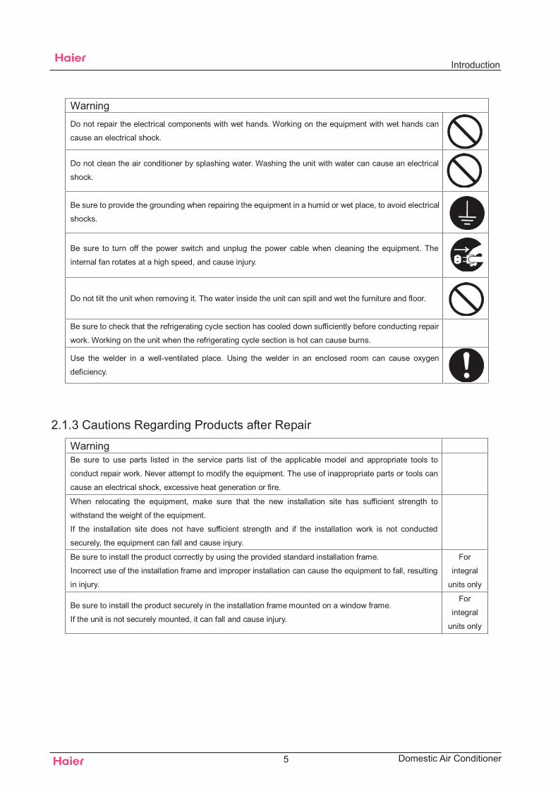
WarningDo not repair the electrical components with wet hands. Working on the equipment with wet hands can
cause an electrical shock.
Do not clean the air conditioner by splashing water. Washing the unit with water can cause an electrical
shock.
Be sure to provide the grounding when repairing the equipment in a humid or wet place, to avoid electrical
shocks.
Be sure to turn off the power switch and unplug the power cable when cleaning the equipment. The
internal fan rotates at a high speed, and cause injury.
Do not tilt the unit when removing it. The water inside the unit can spill and wet the furniture and floor.
Be sure to check that the refrigerating cycle section has cooled down sufficiently before conducting repair
work. Working on the unit when the refrigerating cycle section is hot can cause burns.
Use the welder in a well-ventilated place. Using the welder in an enclosed room can cause oxygen
deficiency.
2.1.3 Cautions Regarding Products after Repair
WarningBe sure to use parts listed in the service parts list of the applicable model and appropriate tools to
conduct repair work. Never attempt to modify the equipment. The use of inappropriate parts or tools can
cause an electrical shock, excessive heat generation or fire.
When relocating the equipment, make sure that the new installation site has sufficient strength to
withstand the weight of the equipment.
If the installation site does not have sufficient strength and if the installation work is not conducted
securely, the equipment can fall and cause injury.
Be sure to install the product correctly by using the provided standard installation frame.
Incorrect use of the installation frame and improper installation can cause the equipment to fall, resulting
in injury.
For
integral
units only
Be sure to install the product securely in the installation frame mounted on a window frame.
If the unit is not securely mounted, it can fall and cause injury.
For
integral
units only
5
Introduction
Domestic Air Conditioner
6
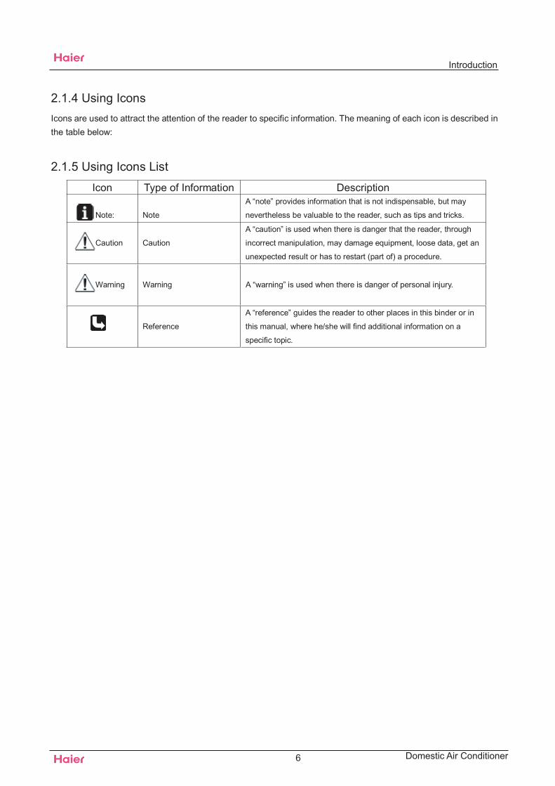
2.1.4 Using IconsIcons are used to attract the attention of the reader to specific information. The meaning of each icon is described inthe table below:
2.1.5 Using Icons List
Icon Type of Information Description
Note: Note
A “note” provides information that is not indispensable, but may
nevertheless be valuable to the reader, such as tips and tricks.
Caution Caution
A “caution” is used when there is danger that the reader, through
incorrect manipulation, may damage equipment, loose data, get an
unexpected result or has to restart (part of) a procedure.
Warning Warning A “warning” is used when there is danger of personal injury.
Reference
A “reference” guides the reader to other places in this binder or in
this manual, where he/she will find additional information on a
specific topic.
Introduction
Domestic Air Conditioner
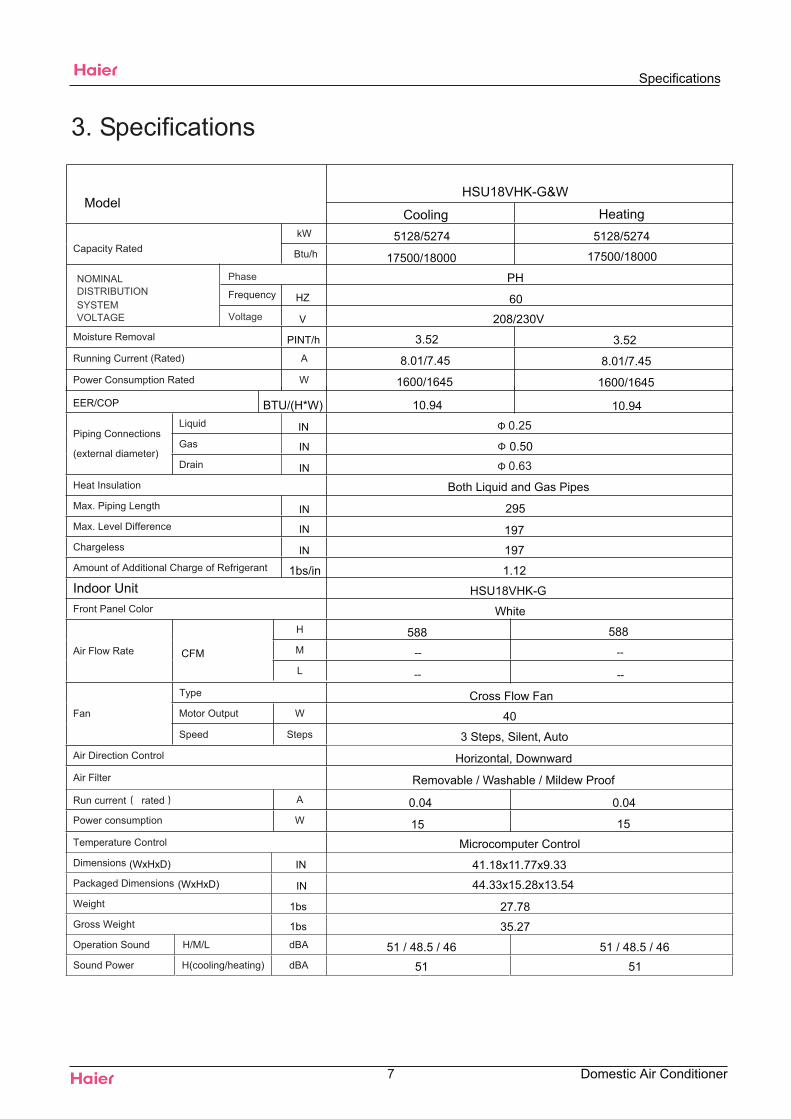
HSU18VHK-G&W
EER/COP
0.63
295
197
--
--
(WxHxD)
(WxHxD)
0.25
HZ
V
197
7
Specifications
Domestic Air Conditioner
Heating
PH
60
208/230V
17500/18000
5128/5274 5128/5274
17500/18000
8.01/7.45 8.01/7.45
1600/1645 1600/1645
Both Liquid and Gas Pipes
White
--
40
Cross Flow Fan
--
3 Steps, Silent, Auto
Horizontal, Downward
Removable / Washable / Mildew Proof
0.04
15
0.04
15
Microcomputer Control
51 / 48.5 / 46 51 / 48.5 / 4651 51
CoolingModel
Indoor Unit
PINT/h 3.52 3.52
10.94 10.94
CFM
588 588
BTU/(H*W)
1bs
1bs 27.78
35.27
IN
IN
IN
0.50
IN
IN
1.121bs/in
IN
41.18x11.77x9.33
44.33x15.28x13.54
IN
IN
HSU18VHK-G
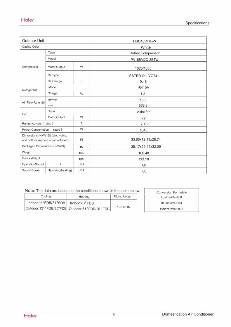
1.3
18.3568.3
R410A
Axial fan
0.48
196.85 IN3413
Rotary Compressor
Specifications
8 Domesfication Air Conditioner
Conversion FormulateHeating
0FDB/71Indoor:95 0FDB0FDB/85Outdoor:121 0FDB
Indoor:73 0 FDBOutdoor:31 0 FDB/28 0 FDB
Outdoor Unit
1bs
1bs 106.48
113.10
33.86x12.13x28.74IN
IN 39.17x16.54x32.09
PA165M2C-3ETU
1625/1635
ESTER OIL VG74
7.45
72
1645
60
60
WhiteHSU18VHK-W
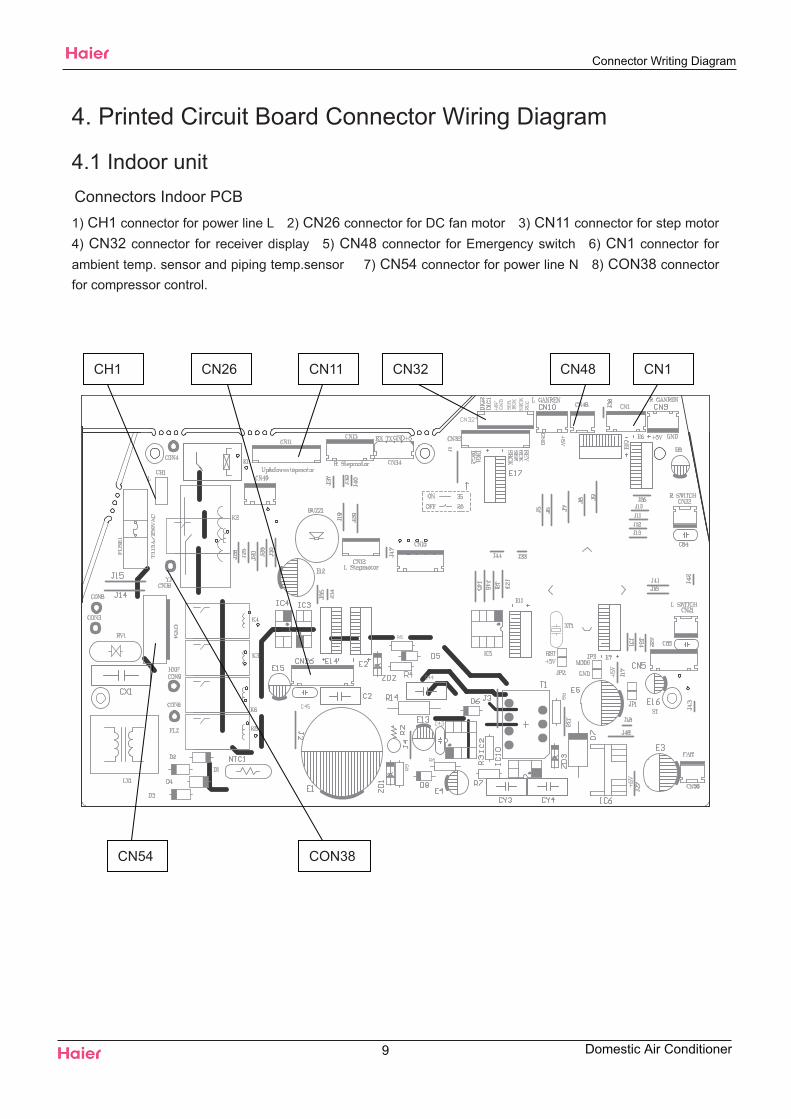
4. Printed Circuit Board Connector Wiring Diagram
4.1 Indoor unit Connectors Indoor PCB1) CH1 connector for power line L 2) CN26 connector for DC fan motor 3) CN11 connector for step motor4) CN32 connector for receiver display 5) CN48 connector for Emergency switch 6) CN1 connector forambient temp. sensor and piping temp.sensor 7) CN54 connector for power line N 8) CON38 connectorfor compressor control.
CN48CN26CH1 CN11 CN1CN32
CN54 CON38
Connector Writing Diagram
9 Domestic Air Conditioner
5 Functions and control5.1 main functions and control specifications Including brief introduction to air conditioners of series models and electric control function.5.1.1 Automatic running5.1.1.1 Single cold automatic run mode:
After entering into this mode, the main control “MCU” determines the corresponding work patternaccording to the indoor temperature so as to maintain the preset temperature (the preset temperature is ).When the indoor temperature is below , outlet air from compressor is off, the automatic wind from fanmotor is low, and wind can be set to high, medium or low by hand. When the indoor temperature is or above
, the unit enters the cooling mode and conducts the cooling programme (the preset temperature is ),outlet air from compressor is on and indoor fan motor run in fixed wind speed.5.1.1.2 Automatic running mode
When the running mode is turned to automation after starting the system, the system will first determinethe running mode according to the current room temperature and then will run according to the determinedmode. Tr in the following selection conditions means room temperature, Ts means setting temperature, Tpmeans temperature of indoor coil pipe
a. Tr running cooling modeb. Tr< running heating mode
After turning to the automation mode, the running mode can be switched between cooling mode, fanmode and heating mode according to the change of the indoor ambient temperature. But the automaticconversion between cooling mode and heating mode must be conducted after 15 minutes.
5.1.2 Indoor temperature controlTemperature control range : —Temperature control precision:Compressor can’t be controlled by temperature sensor within 2 minutes after it starts
5.1.2.1 Cooling mode:When Tr> Ts, outdoor fan motor and compressor on, and indoor fan motor run at fixed wind speed. When TrTs, outdoor fan motor and compressor off, and when Tr > Ts, outdoor fan motor and compressor are working
again .If Tr=Ts, the indoor fan motor , outdoor fan motor and the compressor’s state will not change.5.1.2.2 Heating mode:When Tr Ts, compressor, four-ways valve and outdoor fan motor is on, indoor fan
motor runs as in cold blast avoidance mode, and 4 of compensation is added after compressor is started.When Tr>Ts+5 , compressor is off, and the indoor fan motor runs as in cold blast avoidance mode.When Tr<Ts+5 , compressor, four-ways valve and outdoor fan motor is on, and the indoor fan motor runs
as in the mode of avoiding cold blast.
5.1.3 Cooling run mode:temperature control range :temperature control precision:compressor can’t be controlled by temperature sensor within 2 minutes after it starts.control character: when Tr Ts, outlet air from compressor is on and indoor fan motor run at fixed
wind speed. When Tr Ts, outlet air from compressor is off , and when Tr > Ts, outlet air from compressoris on.
10
Functions and Control
Domestic Air Conditioner
0F920F92
0F920F92
0F830F83
0F60 0F1050F12
—0F60 0F1050F12
Functions and Control
Domestic Air Conditioner
0F120F19
0F12
0F207
0F9
0F201
0F31
0F60 0F105
0F15
0F15
0F19
0F12
Functions and Control
12 Domestic Air Conditioner
0F1050F60
0F15
0F250F25
0F22
0F15
0F830F83
0F131
0F131
0F131 0F131
0F83 0F73
0F1880F175
0F12
Function and Control
13 Domestic Air Conditioner
0F169
0F22
0F131
0F1310F9
0F131
0F131
0F60
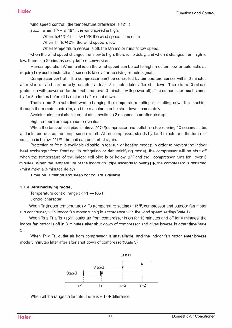
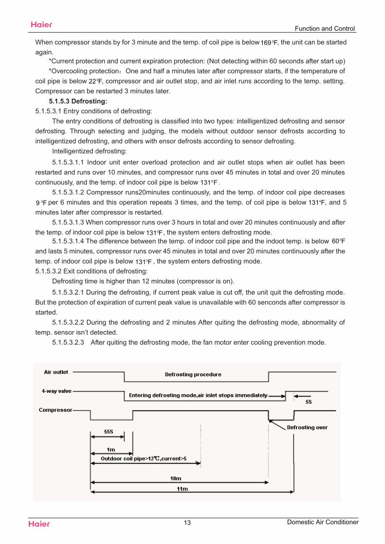
5.1.6 Timer function:You can set 24-hour timer on or timer off as required, and the minum time unit is 1 minute. After
setting, the indicator of indoor unit is on , and it is off when timer setting is completed. There are severaltimer mode as follows.
5.1.6.1 Timer on: The LED of “timer on” lights up, and unit behaves with halt status. Timer on iscompleted, and then unit starts running with the LED of “timer on” off. The unit starts with the the lastsetting receiving timer signals, and sleep setting is not allowed.
5.1.6.2 Timer off: Unit starts, timer indicator lights up; When reaching time setting, the indicatorgoes out, unit enters shut down mode, and sleep function can be set. If timer off and sleep are setsynchronously, the one which time is short run first. Executing shutdown instruction clear timer and sleepfunction.
5.1.6.3 Timer on and timer off can be set synchronously.5.1.7 Sleep function: the timer indicator lights up.
5.1.7.1 In cooling/defrosting mode, the temp. setting increases one hour later after start up.After another hour the temp. setting increase by more and then run continuously for another 6 hoursand then close.
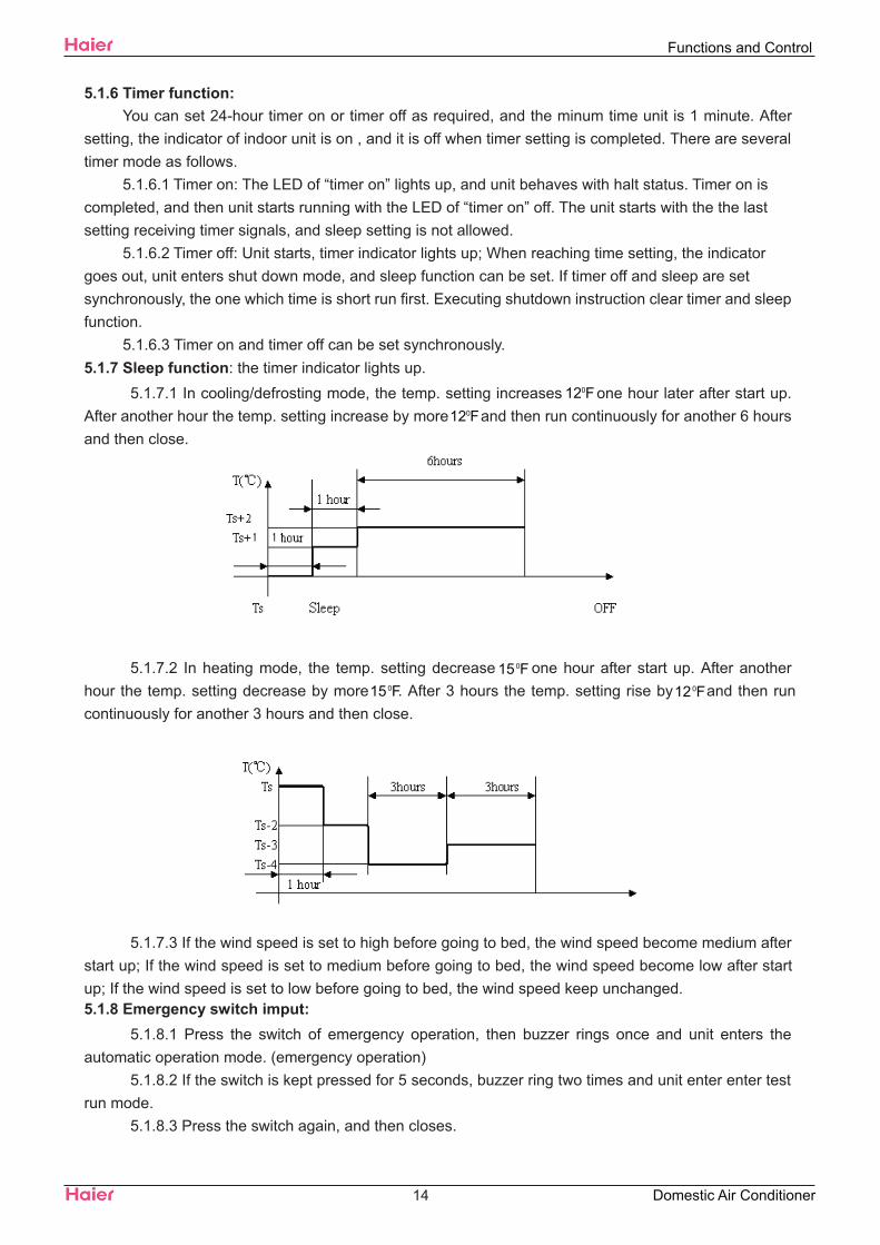
5.1.7.2 In heating mode, the temp. setting decrease one hour after start up. After anotherhour the temp. setting decrease by more . After 3 hours the temp. setting rise by and then runcontinuously for another 3 hours and then close.
5.1.7.3 If the wind speed is set to high before going to bed, the wind speed become medium afterstart up; If the wind speed is set to medium before going to bed, the wind speed become low after startup; If the wind speed is set to low before going to bed, the wind speed keep unchanged.5.1.8 Emergency switch imput:
5.1.8.1 Press the switch of emergency operation, then buzzer rings once and unit enters theautomatic operation mode. (emergency operation)
5.1.8.2 If the switch is kept pressed for 5 seconds, buzzer ring two times and unit enter enter testrun mode.
5.1.8.3 Press the switch again, and then closes.
14
Functions and Control
Domestic Air Conditioner
0F120F12
0F150F15 0F12
5.1.8.4 Enter emergency operation from timer mode, then timer is cancelled.5.1.9 Test run:
5.1.9.1 The temperature sensor of inlet air doesn’t work, and compressor starts (but subject to thelimit of -minute delay excluding the first time), and high wind, cooling, and air door is open.The indoor fanmotor runs, running indicator lights up, compressor relay and the one of outdoor fan motor is closed
5.1.9.2 During test run:The prevention of freezing of evaporator doesn’t work.Current cross control doesn’t work.The control of current cross peak expiration doesn’t work.Temperature control doesn’t work.Temperature expiration control doesn’t work.
5.1.10 memory function The memory function of power down is available, and the auto recoveryfunction of power on is optional. (In auto, heating, cooling, or defrosting status, press the “sleeping”button 10 times within 5 seconds, and the auto recovery function of power on can be set on/off. If thebuzzer rings 4 times, the the auto recovery function of power on is available; If the buzzer rings 2 times,the the auto recovery function of power on is unavailable.)
If there is no EEPROM, the unit is taken off the ‘off’ function of the memory function of power down.But the memory function of power down can also be set on/off, and the data is the default value of chip.5.1.11 Alarm from indoor fan motor: 2 minutes later after the indoor fan motor is charged, and theimpulse from fan motor is not detected, hen send alarm signals.
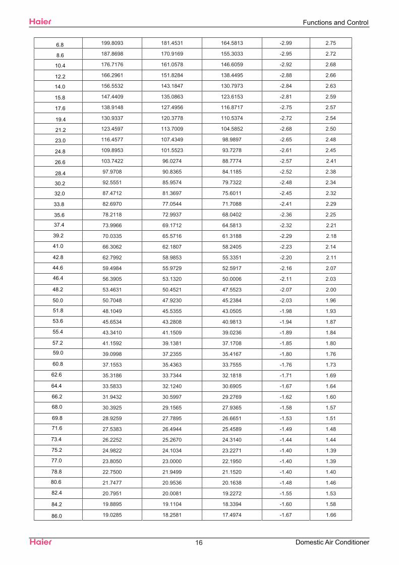
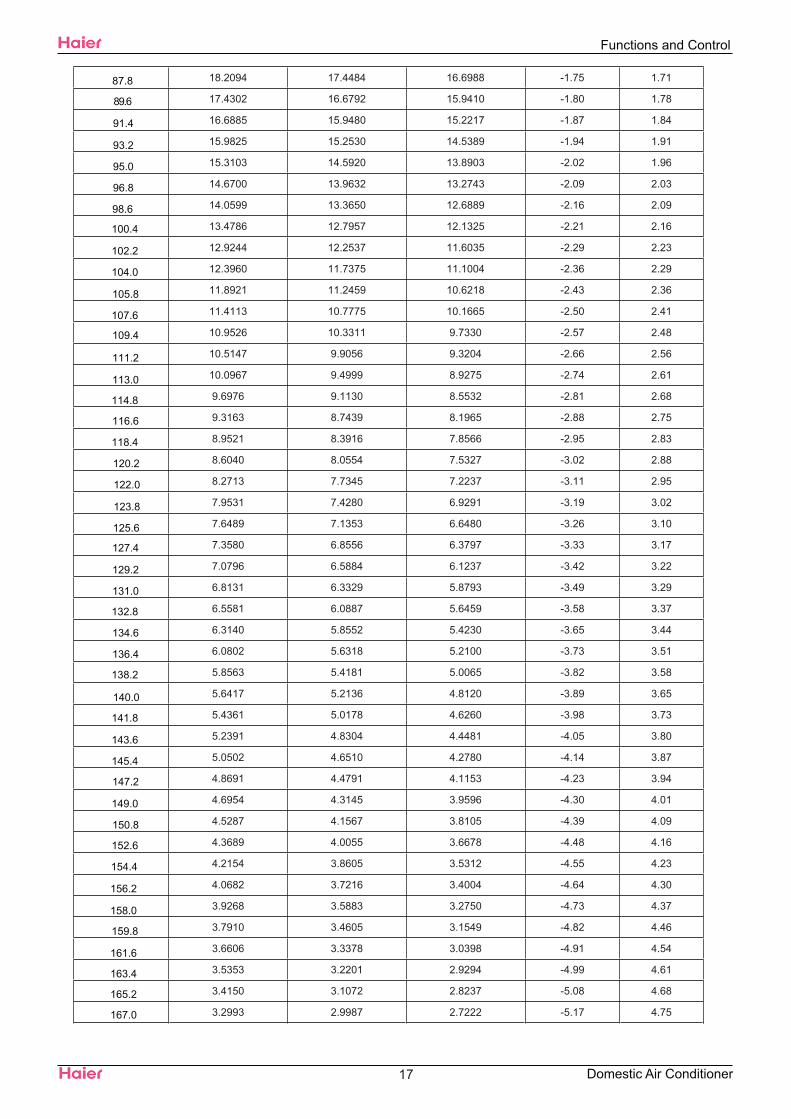
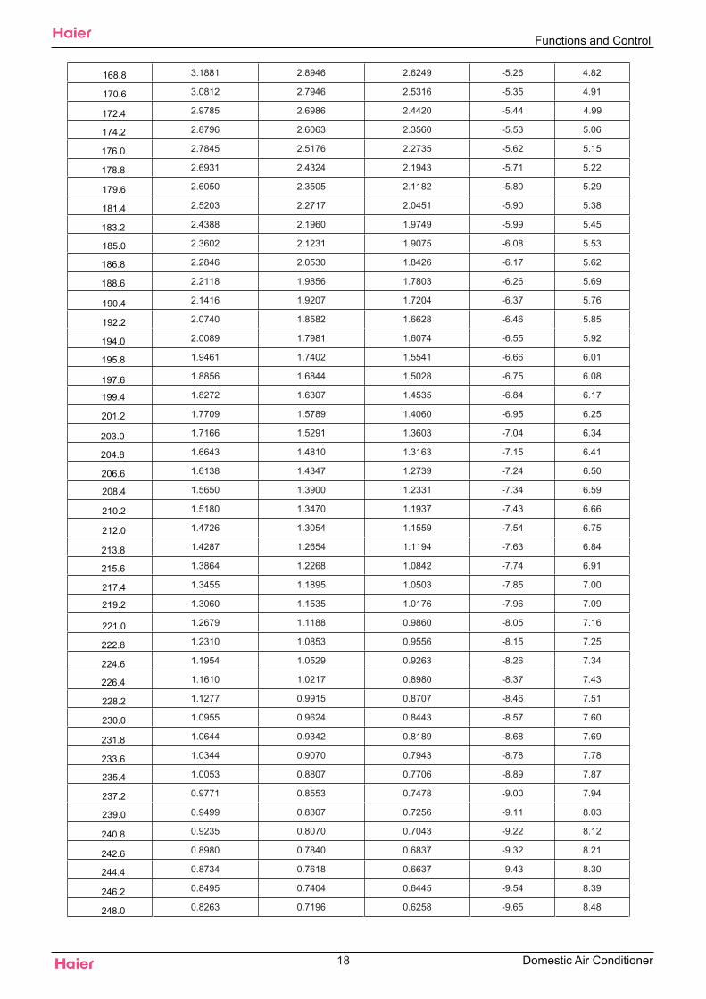
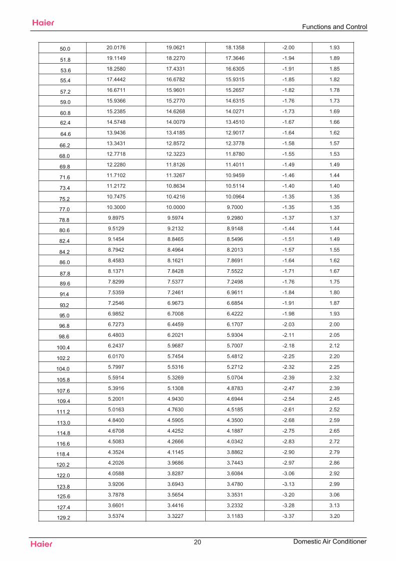
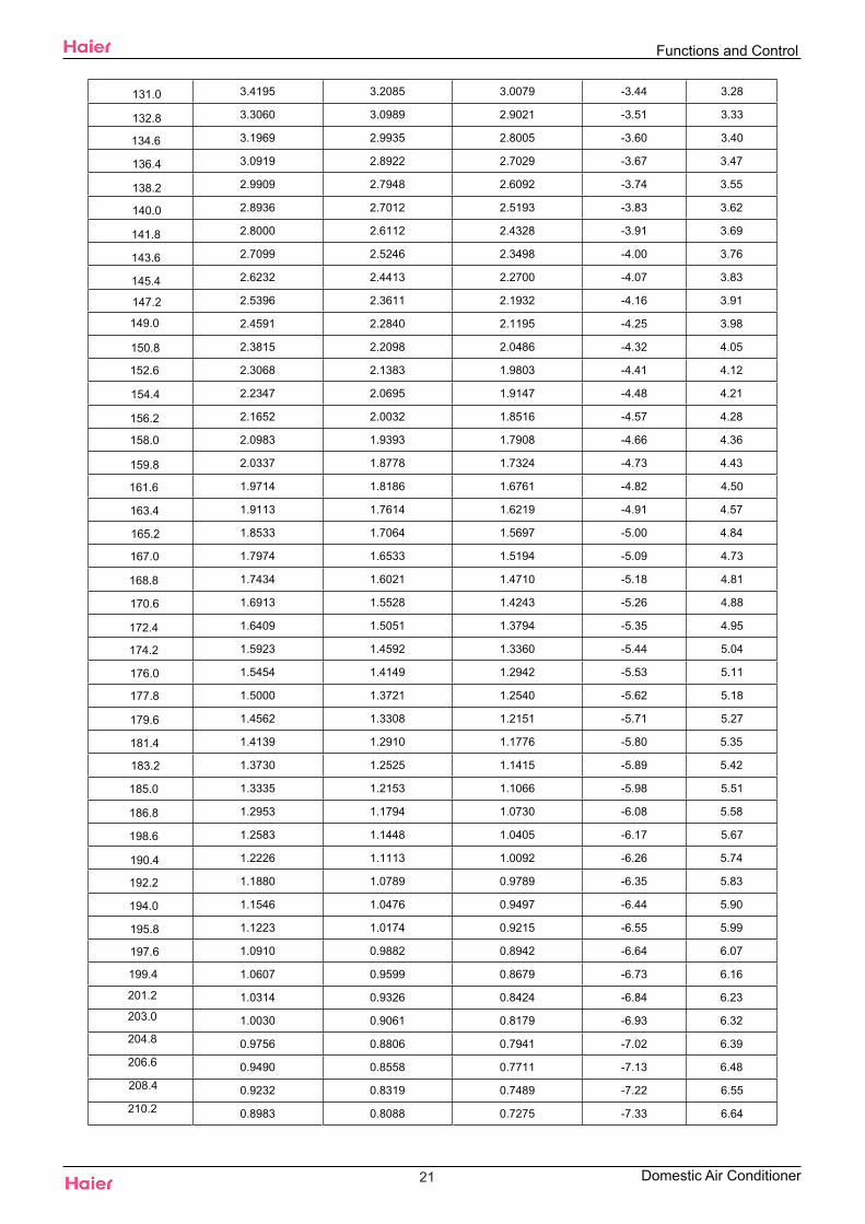
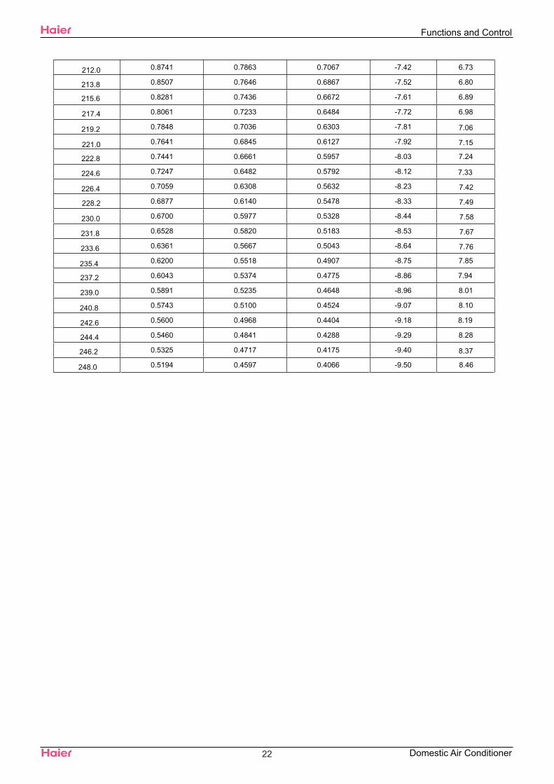
5.2 Value of Thermistor
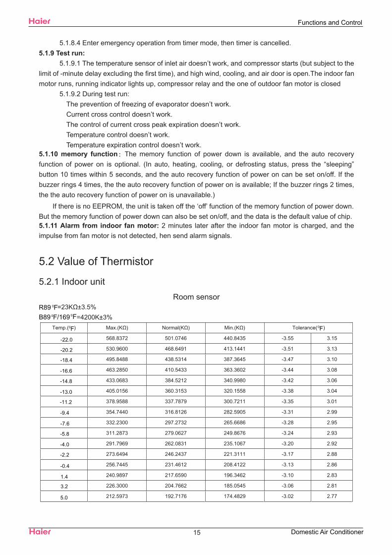
5.2.1 Indoor unitRoom sensor
=23K ±3.5%=4200K±3%
Temp.( ) Max.(K ) Normal(K ) Min.(K ) Tolerance( )
568.8372 501.0746 440.8435 -3.55 3.15
530.9600 468.6491 413.1441 -3.51 3.13
495.8488 438.5314 387.3645 -3.47 3.10
463.2850 410.5433 363.3602 -3.44 3.08
433.0683 384.5212 340.9980 -3.42 3.06
405.0156 360.3153 320.1558 -3.38 3.04
378.9588 337.7879 300.7211 -3.35 3.01
354.7440 316.8126 282.5905 -3.31 2.99
332.2300 297.2732 265.6686 -3.28 2.95
311.2873 279.0627 249.8676 -3.24 2.93
291.7969 262.0831 235.1067 -3.20 2.92
273.6494 246.2437 221.3111 -3.17 2.88
256.7445 231.4612 208.4122 -3.13 2.86
240.9897 217.6590 196.3462 -3.10 2.83
226.3000 204.7662 185.0545 -3.06 2.81
212.5973 192.7176 174.4829 -3.02 2.77
15
Functions and Control
Domestic Air Conditioner
0FR890F/169B89 0F
-22.0
-20.2
-18.4
-16.6
-14.8
-13.0
-11.2
-9.4
-7.6
-5.8
-4.0
-2.2
-0.4
1.4
3.2
5.0
0F 0F
199.8093 181.4531 164.5813 -2.99 2.75
187.8698 170.9169 155.3033 -2.95 2.72
176.7176 161.0578 146.6059 -2.92 2.68
166.2961 151.8284 138.4495 -2.88 2.66
156.5532 143.1847 130.7973 -2.84 2.63
147.4409 135.0863 123.6153 -2.81 2.59
138.9148 127.4956 116.8717 -2.75 2.57
130.9337 120.3778 110.5374 -2.72 2.54
123.4597 113.7009 104.5852 -2.68 2.50
116.4577 107.4349 98.9897 -2.65 2.48
109.8953 101.5523 93.7278 -2.61 2.45
103.7422 96.0274 88.7774 -2.57 2.41
97.9708 90.8365 84.1185 -2.52 2.38
92.5551 85.9574 79.7322 -2.48 2.34
87.4712 81.3697 75.6011 -2.45 2.32
82.6970 77.0544 71.7088 -2.41 2.29
78.2118 72.9937 68.0402 -2.36 2.25
73.9966 69.1712 64.5813 -2.32 2.21
70.0335 65.5716 61.3188 -2.29 2.18
66.3062 62.1807 58.2405 -2.23 2.14
62.7992 58.9853 55.3351 -2.20 2.11
59.4984 55.9729 52.5917 -2.16 2.07
56.3905 53.1320 50.0006 -2.11 2.03
53.4631 50.4521 47.5523 -2.07 2.00
50.7048 47.9230 45.2384 -2.03 1.96
48.1049 45.5355 43.0505 -1.98 1.93
45.6534 43.2808 40.9813 -1.94 1.87
43.3410 41.1509 39.0236 -1.89 1.84
41.1592 39.1381 37.1708 -1.85 1.80
39.0998 37.2355 35.4167 -1.80 1.76
37.1553 35.4363 33.7555 -1.76 1.73
35.3186 33.7344 32.1818 -1.71 1.69
33.5833 32.1240 30.6905 -1.67 1.64
31.9432 30.5997 29.2769 -1.62 1.60
30.3925 29.1565 27.9365 -1.58 1.57
28.9259 27.7895 26.6651 -1.53 1.51
27.5383 26.4944 25.4589 -1.49 1.48
26.2252 25.2670 24.3140 -1.44 1.44
24.9822 24.1034 23.2271 -1.40 1.39
23.8050 23.0000 22.1950 -1.40 1.39
22.7500 21.9499 21.1520 -1.40 1.40
21.7477 20.9536 20.1638 -1.48 1.46
20.7951 20.0081 19.2272 -1.55 1.53
19.8895 19.1104 18.3394 -1.60 1.58
19.0285 18.2581 17.4974 -1.67 1 . 66
16
Functions and Control
Domestic Air Conditioner
6.8
8.6
10.4
12.2
14.0
15.8
17.6
19.4
21.2
23.0
24.8
26.6
28.4
30.2
32.0
33.8
35.6
37.4
39.2
41.0
42.8
44.6
46.4
48.2
50.0
51.8
53.6
55.4
57.2
59.0
60.8
62.6
64.4
66.2
68.0
69.8
71.6
73.4
75.2
77.0
78.8
80.6
82.4
84.2
86.0
18.2094 17.4484 16.6988 -1.75 1.71
17.4302 16.6792 15.9410 -1.80 1.78
16.6885 15.9480 15.2217 -1.87 1.84
15.9825 15.2530 14.5389 -1.94 1.91
15.3103 14.5920 13.8903 -2.02 1.96
14.6700 13.9632 13.2743 -2.09 2.03
14.0599 13.3650 12.6889 -2.16 2.09
13.4786 12.7957 12.1325 -2.21 2.16
12.9244 12.2537 11.6035 -2.29 2.23
12.3960 11.7375 11.1004 -2.36 2.29
11.8921 11.2459 10.6218 -2.43 2.36
11.4113 10.7775 10.1665 -2.50 2.41
10.9526 10.3311 9.7330 -2.57 2.48
10.5147 9.9056 9.3204 -2.66 2.56
10.0967 9.4999 8.9275 -2.74 2.61
9.6976 9.1130 8.5532 -2.81 2.68
9.3163 8.7439 8.1965 -2.88 2.75
8.9521 8.3916 7.8566 -2.95 2.83
8.6040 8.0554 7.5327 -3.02 2.88
8.2713 7.7345 7.2237 -3.11 2.95
7.9531 7.4280 6.9291 -3.19 3.02
7.6489 7.1353 6.6480 -3.26 3.10
7.3580 6.8556 6.3797 -3.33 3.17
7.0796 6.5884 6.1237 -3.42 3.22
6.8131 6.3329 5.8793 -3.49 3.29
6.5581 6.0887 5.6459 -3.58 3.37
6.3140 5.8552 5.4230 -3.65 3.44
6.0802 5.6318 5.2100 -3.73 3.51
5.8563 5.4181 5.0065 -3.82 3.58
5.6417 5.2136 4.8120 -3.89 3.65
5.4361 5.0178 4.6260 -3.98 3.73
5.2391 4.8304 4.4481 -4.05 3.80
5.0502 4.6510 4.2780 -4.14 3.87
4.8691 4.4791 4.1153 -4.23 3.94
4.6954 4.3145 3.9596 -4.30 4.01
4.5287 4.1567 3.8105 -4.39 4.09
4.3689 4.0055 3.6678 -4.48 4.16
4.2154 3.8605 3.5312 -4.55 4.23
4.0682 3.7216 3.4004 -4.64 4.30
3.9268 3.5883 3.2750 -4.73 4.37
3.7910 3.4605 3.1549 -4.82 4.46
3.6606 3.3378 3.0398 -4.91 4.54
3.5353 3.2201 2.9294 -4.99 4.61
3.4150 3.1072 2.8237 -5.08 4.68
3.2993 2.9987 2.7222 -5.17 4.75
17
Functions and Control
Domestic Air Conditioner
87.8
89.6
91.4
93.2
95.0
96.8
98.6
100.4
102.2
104.0
105.8
107.6
109.4
111.2
113.0
114.8
116.6
118.4
120.2
122.0
123.8
125.6
127.4
129.2
131.0
132.8
134.6
136.4
138.2
140.0
141.8
143.6
145.4
147.2
149.0
150.8
152.6
154.4
156.2
158.0
159.8
161.6
163.4
165.2
167.0
3.1881 2.8946 2.6249 -5.26 4.82
3.0812 2.7946 2.5316 -5.35 4.91
2.9785 2.6986 2.4420 -5.44 4.99
2.8796 2.6063 2.3560 -5.53 5.06
2.7845 2.5176 2.2735 -5.62 5.15
2.6931 2.4324 2.1943 -5.71 5.22
2.6050 2.3505 2.1182 -5.80 5.29
2.5203 2.2717 2.0451 -5.90 5.38
2.4388 2.1960 1.9749 -5.99 5.45
2.3602 2.1231 1.9075 -6.08 5.53
2.2846 2.0530 1.8426 -6.17 5.62
2.2118 1.9856 1.7803 -6.26 5.69
2.1416 1.9207 1.7204 -6.37 5.76
2.0740 1.8582 1.6628 -6.46 5.85
2.0089 1.7981 1.6074 -6.55 5.92
1.9461 1.7402 1.5541 -6.66 6.01
1.8856 1.6844 1.5028 -6.75 6.08
1.8272 1.6307 1.4535 -6.84 6.17
1.7709 1.5789 1.4060 -6.95 6.25
1.7166 1.5291 1.3603 -7.04 6.34
1.6643 1.4810 1.3163 -7.15 6.41
1.6138 1.4347 1.2739 -7.24 6.50
1.5650 1.3900 1.2331 -7.34 6.59
1.5180 1.3470 1.1937 -7.43 6.66
1.4726 1.3054 1.1559 -7.54 6.75
1.4287 1.2654 1.1194 -7.63 6.84
1.3864 1.2268 1.0842 -7.74 6.91
1.3455 1.1895 1.0503 -7.85 7.00
1.3060 1.1535 1.0176 -7.96 7.09
1.2679 1.1188 0.9860 -8.05 7.16
1.2310 1.0853 0.9556 -8.15 7.25
1.1954 1.0529 0.9263 -8.26 7.34
1.1610 1.0217 0.8980 -8.37 7.43
1.1277 0.9915 0.8707 -8.46 7.51
1.0955 0.9624 0.8443 -8.57 7.60
1.0644 0.9342 0.8189 -8.68 7.69
1.0344 0.9070 0.7943 -8.78 7.78
1.0053 0.8807 0.7706 -8.89 7.87
0.9771 0.8553 0.7478 -9.00 7.94
0.9499 0.8307 0.7256 -9.11 8.03
0.9235 0.8070 0.7043 -9.22 8.12
0.8980 0.7840 0.6837 -9.32 8.21
0.8734 0.7618 0.6637 -9.43 8.30
0.8495 0.7404 0.6445 -9.54 8.39
0.8263 0.7196 0.6258 -9.65 8.48
18
Functions and Control
Domestic Air Conditioner
168.8
170.6
172.4
174.2
176.0
178.8
179.6
181.4
183.2
185.0
186.8
188.6
190.4
192.2
194.0
195.8
197.6
199.4
201.2
203.0
204.8
206.6
208.4
210.2
212.0
213.8
215.6
217.4
219.2
221.0
222.8
224.6
226.4
228.2
230.0
231.8
233.6
235.4
237.2
239.0
240.8
242.6
244.4
246.2
248.0
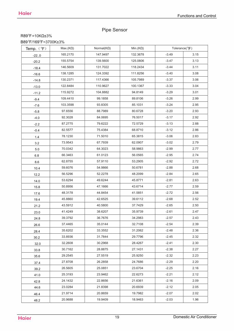
Pipe Sensor=10K ±3%
=3700K±3%Max.(K ) Normal(K ) Min.(K ) Tolerance( )
165.2170 147.9497 132.3678 -3.49 3.15
155.5754 139.5600 125.0806 -3.47 3.13
146.5609 131.7022 118.2434 -3.44 3.11
138.1285 124.3392 111.8256 -3.40 3.08
130.2371 117.4366 105.7989 -3.37 3.06
122.8484 110.9627 100.1367 -3.33 3.04
115.9272 104.8882 94.8149 -3.29 3.01
109.4410 99.1858 89.8106 -3.26 2.99
103.3598 93.8305 85.1031 -3.24 2.95
97.6556 88.7989 80.6728 -3.20 2.93
92.3028 84.0695 76.5017 -3.17 2.92
87.2775 79.6222 72.5729 -3.13 2.88
82.5577 75.4384 68.8710 -3.12 2.86
78.1230 71.5010 65.3815 -3.06 2.83
73.9543 67.7939 62.0907 -3.02 2.79
70.0342 64.3023 58.9863 -2.99 2.77
66.3463 61.0123 56.0565 -2.95 2.74
62.8755 57.9110 53.2905 -2.92 2.72
59.6076 54.9866 50.6781 -2.88 2.68
56.5296 52.2278 48.2099 -2.84 2.65
53.6294 49.6244 45.8771 -2.81 2.63
50.8956 47.1666 43.6714 -2.77 2.59
48.3178 44.8454 41.5851 -2.72 2.56
45.8860 42.6525 39.6112 -2.68 2.52
43.5912 40.5800 37.7429 -2.65 2.50
41.4249 38.6207 35.9739 -2.61 2.47
39.3792 36.7676 34.2983 -2.57 2.43
37.4465 35.0144 32.7108 -2.54 2.39
35.6202 33.3552 31.2062 -2.48 2.36
33.8936 31.7844 29.7796 -2.45 2.32
32.2608 30.2968 28.4267 -2.41 2.30
30.7162 28.8875 27.1431 -2.38 2.27
29.2545 27.5519 25.9250 -2.32 2.23
27.8708 26.2858 24.7686 -2.29 2.20
26.5605 25.0851 23.6704 -2.25 2.16
25.3193 23.9462 22.6273 -2.21 2.12
24.1432 22.8656 21.6361 -2.16 2.09
23.0284 21.8398 20.6939 -2.12 2.05
21.9714 20.8659 19.7982 -2.07 2.02
20.9688 19.9409 18.9463 -2.03 1.96
19
Functions and Control
Domestic Air Conditioner
R890F
0F
B89 0F/1690F
Temp.
-22..0
-20.2
-18.4
-16.6
-14.8
-13.0
-11.2
-9.4
-7.6
-5.8
-4.0
-2.2
-0.4
1.4
3.2
5.0
6.8
8.6
10.4
12.2
14.0
15.8
17.6
19.4
21.2
23.0
24.8
26.6
28.4
30.2
33.8
32.0
35.6
37.4
39.2
41.0
42.8
44.6
46.4
48.2
0F
20.0176 19.0621 18.1358 -2.00 1.93
19.1149 18.2270 17.3646 -1.94 1.89
18.2580 17.4331 16.6305 -1.91 1.85
17.4442 16.6782 15.9315 -1.85 1.82
16.6711 15.9601 15.2657 -1.82 1.78
15.9366 15.2770 14.6315 -1.76 1.73
15.2385 14.6268 14.0271 -1.73 1.69
14.5748 14.0079 13.4510 -1.67 1.66
13.9436 13.4185 12.9017 -1.64 1.62
13.3431 12.8572 12.3778 -1.58 1.57
12.7718 12.3223 11.8780 -1.55 1.53
12.2280 11.8126 11.4011 -1.49 1.49
11.7102 11.3267 10.9459 -1.46 1.44
11.2172 10.8634 10.5114 -1.40 1.40
10.7475 10.4216 10.0964 -1.35 1.35
10.3000 10.0000 9.7000 -1.35 1.35
9.8975 9.5974 9.2980 -1.37 1.37
9.5129 9.2132 8.9148 -1.44 1.44
9.1454 8.8465 8.5496 -1.51 1.49
8.7942 8.4964 8.2013 -1.57 1.55
8.4583 8.1621 7.8691 -1.64 1.62
8.1371 7.8428 7.5522 -1.71 1.67
7.8299 7.5377 7.2498 -1.76 1.75
7.5359 7.2461 6.9611 -1.84 1.80
7.2546 6.9673 6.6854 -1.91 1.87
6.9852 6.7008 6.4222 -1.98 1.93
6.7273 6.4459 6.1707 -2.03 2.00
6.4803 6.2021 5.9304 -2.11 2.05
6.2437 5.9687 5.7007 -2.18 2.12
6.0170 5.7454 5.4812 -2.25 2.20
5.7997 5.5316 5.2712 -2.32 2.25
5.5914 5.3269 5.0704 -2.39 2.32
5.3916 5.1308 4.8783 -2.47 2.39
5.2001 4.9430 4.6944 -2.54 2.45
5.0163 4.7630 4.5185 -2.61 2.52
4.8400 4.5905 4.3500 -2.68 2.59
4.6708 4.4252 4.1887 -2.75 2.65
4.5083 4.2666 4.0342 -2.83 2.72
4.3524 4.1145 3.8862 -2.90 2.79
4.2026 3.9686 3.7443 -2.97 2.86
4.0588 3.8287 3.6084 -3.06 2.92
3.9206 3.6943 3.4780 -3.13 2.99
3.7878 3.5654 3.3531 -3.20 3.06
3.6601 3.4416 3.2332 -3.28 3.13
3.5374 3.3227 3.1183 -3.37 3.20
20
Functions and Control
Domestic Air Conditioner
50.0
51.8
53.6
55.4
57.2
59.0
60.8
62.4
64.6
66.2
68.0
69.8
71.6
73.4
75.2
77.0
78.8
80.6
82.4
84.2
86.0
87.8
89.6
91.4
93.2
95.0
96.8
98.6
100.4
102.2
104.0
105.8
107.6
109.4
111.2
113.0
114.8
116.6
118.4
120.2
122.0
123.8
125.6
127.4
129.2
3.4195 3.2085 3.0079 -3.44 3.28
3.3060 3.0989 2.9021 -3.51 3.33
3.1969 2.9935 2.8005 -3.60 3.40
3.0919 2.8922 2.7029 -3.67 3.47
2.9909 2.7948 2.6092 -3.74 3.55
2.8936 2.7012 2.5193 -3.83 3.62
2.8000 2.6112 2.4328 -3.91 3.69
2.7099 2.5246 2.3498 -4.00 3.76
2.6232 2.4413 2.2700 -4.07 3.83
2.5396 2.3611 2.1932 -4.16 3.91
2.4591 2.2840 2.1195 -4.25 3.98
2.3815 2.2098 2.0486 -4.32 4.05
2.3068 2.1383 1.9803 -4.41 4.12
2.2347 2.0695 1.9147 -4.48 4.21
2.1652 2.0032 1.8516 -4.57 4.28
2.0983 1.9393 1.7908 -4.66 4.36
2.0337 1.8778 1.7324 -4.73 4.43
1.9714 1.8186 1.6761 -4.82 4.50
1.9113 1.7614 1.6219 -4.91 4.57
1.8533 1.7064 1.5697 -5.00 4.84
1.7974 1.6533 1.5194 -5.09 4.73
1.7434 1.6021 1.4710 -5.18 4.81
1.6913 1.5528 1.4243 -5.26 4.88
1.6409 1.5051 1.3794 -5.35 4.95
1.5923 1.4592 1.3360 -5.44 5.04
1.5454 1.4149 1.2942 -5.53 5.11
1.5000 1.3721 1.2540 -5.62 5.18
1.4562 1.3308 1.2151 -5.71 5.27
1.4139 1.2910 1.1776 -5.80 5.35
1.3730 1.2525 1.1415 -5.89 5.42
1.3335 1.2153 1.1066 -5.98 5.51
1.2953 1.1794 1.0730 -6.08 5.58
1.2583 1.1448 1.0405 -6.17 5.67
1.2226 1.1113 1.0092 -6.26 5.74
1.1880 1.0789 0.9789 -6.35 5.83
1.1546 1.0476 0.9497 -6.44 5.90
1.1223 1.0174 0.9215 -6.55 5.99
1.0910 0.9882 0.8942 -6.64 6.07
1.0607 0.9599 0.8679 -6.73 6.16
1.0314 0.9326 0.8424 -6.84 6.23
1.0030 0.9061 0.8179 -6.93 6.32
0.9756 0.8806 0.7941 -7.02 6.39
0.9490 0.8558 0.7711 -7.13 6.48
0.9232 0.8319 0.7489 -7.22 6.55
0.8983 0.8088 0.7275 -7.33 6.64
21
Functions and Control
Domestic Air Conditioner
131.0
132.8
134.6
136.4
138.2
140.0
141.8
143.6
145.4
147.2
149.0
150.8
152.6
154.4
156.2
158.0
159.8
161.6
163.4
165.2
167.0
168.8
170.6
172.4
174.2
176.0
177.8
179.6
181.4
183.2
185.0
186.8
198.6
190.4
192.2
194.0
195.8
197.6
199.4
201.2
203.0
204.8
206.6
208.4
210.2
0.8741 0.7863 0.7067 -7.42 6.73
0.8507 0.7646 0.6867 -7.52 6.80
0.8281 0.7436 0.6672 -7.61 6.89
0.8061 0.7233 0.6484 -7.72 6.98
0.7848 0.7036 0.6303 -7.81 7.06
0.7641 0.6845 0.6127 -7.92 7.15
0.7441 0.6661 0.5957 -8.03 7.24
0.7247 0.6482 0.5792 -8.12 7.33
0.7059 0.6308 0.5632 -8.23 7.42
0.6877 0.6140 0.5478 -8.33 7.49
0.6700 0.5977 0.5328 -8.44 7.58
0.6528 0.5820 0.5183 -8.53 7.67
0.6361 0.5667 0.5043 -8.64 7.76
0.6200 0.5518 0.4907 -8.75 7.85
0.6043 0.5374 0.4775 -8.86 7.94
0.5891 0.5235 0.4648 -8.96 8.01
0.5743 0.5100 0.4524 -9.07 8.10
0.5600 0.4968 0.4404 -9.18 8.19
0.5460 0.4841 0.4288 -9.29 8.28
0.5325 0.4717 0.4175 -9.40 8.37
0.5194 0.4597 0.4066 -9.50 8.46
22
Functions and Control
Domestic Air Conditioner
212.0
213.8
217.4
215.6
219.2
221.0
222.8
224.6
226.4
228.2
230.0
231.8
233.6
235.4
237.2
239.0
240.8
242.6
244.4
246.2
248.0
6. System Configuration
6.1 System ConfigurationAfter the installation and test operation of the room air conditioner have been completed, it should be operated andhandled as described below. Every user would like to know the correct method of operation of the room airconditioner, to check if it is capable of cooling (or heating) well, and to know a clever method of using it.In order tomeet this expectation of the users, giving sufficient explanations taking enough time can be said to reduce about80% of the requests for servicing. However good the installation work is and however good the functions are, thecustomer may blame either the room air conditioner or its installation work because of improper handling. Theinstallation work and handing over of the unit can only be considered to have been completed when its handling hasbeen explained to the user without using technical terms but giving full knowledge of the equipment.
23
System Configuration
Domestic Air Conditioner
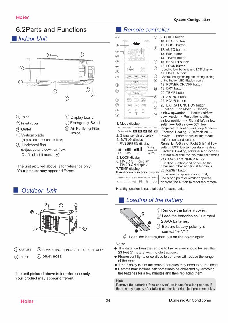
Outdoor UnitLoading of the battery
6.2Parts and FunctionsIndoor Unit
OUTLET
INLET
CONNECTING PIPING AND ELECTRICAL WIRING
DRAIN HOSE
Remote controller
Air Purifying Filter(inside)
Inlet1
Frant cover2
Outlet3
(adjust left and Vertical blade
right air flow)4
Display board
Horizontal flap(adjust up and down air flow.
Don't adjust it manually)
Emergency Switch6
7
8
5
1
2
3
4
5
6
7
8
4
Healthy function is not available for some units.
1
2
3
4
5
9
10
11
12
13
14
15
16
17
22
23
24
25
19
20
21
8
18
7
6
The unit pictured above is for reference only. Your product may appear different.
The unit pictured above is for reference only. Your product may appear different.
Hint:Remove the batteries if the unit won't be in use for a long period. Ifthere is any display after taking-out the batteries, just press reset key.
1. Mode display
2. Signal sending display
4. FAN SPEED display
5. LOCK display6. TIMER OFF display
TIMER ON display
LO MED HI
7.TEMP display
16. LOCK buttonUsed to lock buttons and LCD display.
25. RESET buttonIf the remote appears abnormal, use a pen point or similar object todepress the button to reset the remote
22. HOUR button
Operation mode AUTO FANCOOL DRY
Remote controller
HEAT
Control the lightening and extinguishing of the indoor LED display board.
3. SWING display
8.
9. QUIET button10. HEAT button11. COOL button12. AUTO button13. FAN button14. TIMER button15. HEALTH button
17. LIGHT button
18. POWER ON/OFF button19. DRY button20. TEMP button21. SWING button
23. EXTRA FUNCTION button
24.CANCEL/CONFIRM button
AUTO
Function: Setting and cancel to the timer and other additional functions.
Displaycirculated
Operation mode
Remote controller
QUITE POWERSLEEP HEALTH
Additional functions display
123
4
Remove the battery cover;Load the batteries as illustrated. 2 AAA batteries.
" + "/"-";Load the battery,then put on the cover again.
Note:
Be sure battery polarity is correct
The distance from the remote to the receiver should be less than 23 feet (7 meters) with no obstructions.Fluorescent lights or cordless telephones will reduce the range of the remote.If the display is dim the remote batteries may need to be replaced.Remote malfunctions can sometimes be corrected by removing the batteries for a few minutes and then replacing them.
Function Fan Mode— Healthy airflow upwarder — Healthy airflow downwarder— Reset the healthy airflow position — Right & left airflow setting— A-B yard— 50 low temperature heating— Sleep Mode—Electrical Heating— Refresh Air—Power — Fahrenheit/Celsius mode shift on unit and remoteRemark A-B yard, Right & left airflow setting, 50 low temperature heating, Electrical Heating, Refresh Air functions are not available for this mini split series.
System Configuration
24 Domestic Air Conditioner
Operation
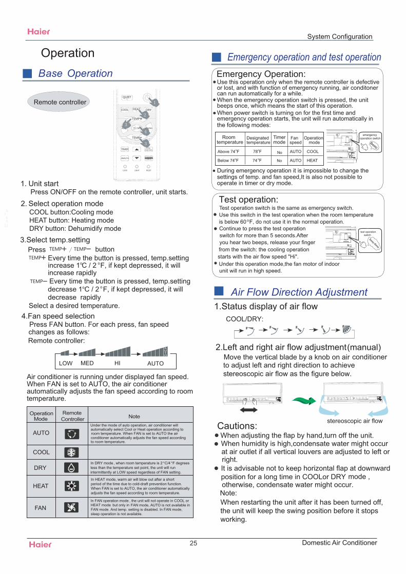
Air Flow Direction Adjustment
Base Operation
1.Status display of air flow
2.Left and right air flow adjustment(manual)
Cautions:When adjusting the flap by hand,turn off the unit.When humidity is high,condensate water might occur
adjusted to left or
It is advisable not to keep horizontal flap at downwardposition for a long time in COOLor DRYotherwise, condensate water might occur.
Emergency operation and test operation
at air outlet if all vertical louvers are right.
mode ,
Note:
test operation switch
Emergency Operation:Use this operation only when the remote controller is defective or lost, and with function of emergency running, air conditonercan run automatically for a while.When the emergency operation switch is pressed, the unit beeps once, which means the start of this operation. When power switch is turning on for the first time andemergency operation starts, the unit will run automatically in the following modes:
emergencyoperation switch
is below 60oF, do not use it in the normal operation.
Test operation:Use this switch in the test operation when the room temperature
from the switch: the cooling operation
Continue to press the test operation switch for more than 5 seconds.After
you hear two beeps, release your finger
starts with the air flow speed "Hi".Under this operation mode,the fan motor of indoorunit will run in high speed.
COOL/DRY:
Test operation switch is the same as emergency switch.
Press FAN button. For each press, fan speed follows:
Remote controller:
Press button
Select a desired temperature.4.Fan speed selection
3.Select temp.setting
Air conditioner is running under displayed fan speed.When FAN is set to AUTO, the air conditionerautomatically adjusts the fan speed according to roomtemperature.
1. Unit start Press ON/OFF on the remote controller, unit starts.
Remote controller
changes as
OperationMode
RemoteController Note
Under the mode of auto operation, air conditioner willautomatically select Cool or Heat operation according toroom temperature. When FAN is set to AUTO the air conditioner automatically adjusts the fan speed accordingto room temperature.
In FAN operation mode , the unit will not operate in COOL orHEAT mode but only in FAN mode, AUTO is not available inFAN mode. And temp. setting is disabled. In FAN mode,sleep operation is not available.
LOW MED HI AUTO
2. Select operation modeCOOL button:Cooling modeHEAT button: Heating modeDRY button: Dehumidify mode
DRY
COOL
AUTO
HEAT
FAN
In HEAT mode, warm air will blow out after a short period of the time due to cold-draft prevention function.When FAN is set to AUTO, the air conditioner automatically adjusts the fan speed according to room temperature.
Roomtemperature
Designatedtemperature
Timermode
Fanspeed
Operationmode
Above 74oF
Below 74oF 74 oF
78oF
No
AUTO
AUTO
COOL
HEAT
No
Every time the button is pressed, temp.settingincrease 1oC / 2 F, if kept depressed, it willincrease rapidlyEvery time the button is pressed, temp.settingdecrease 1oC / 2 F, if kept depressed, it will decrease rapidly
o
o
AUTO
When restarting the unit after it has been turned off, the unit will keep the swing position before it stops working.
During emergency operation it is impossible to change thesettings of temp. and fan speed,It is also not possible to operate in timer or dry mode.
Move the vertical blade by a knob on airto adjust left and right direction to achieve stereoscopic air flow as the figure below.
conditioner
stereoscopic air flow
peeB
peeB-p
eeB
In DRY mode , when room temperature is 2 C/4 F degreeso
less than the temperature set point, the unit will runintermittently at LOW speed regardless of FAN setting.
o
System Configuration
25 Domestic Air Conditioner
Operation Sleep Operation
3. In AUTO mode
4. In FAN mode It has no SLEEP function.
Note
POWER/QUIET Operation
5.Fan Speed in Sleep Mode When the unit is set to sleep mode, the fan speed will be set to low speed and it cannot be changed.
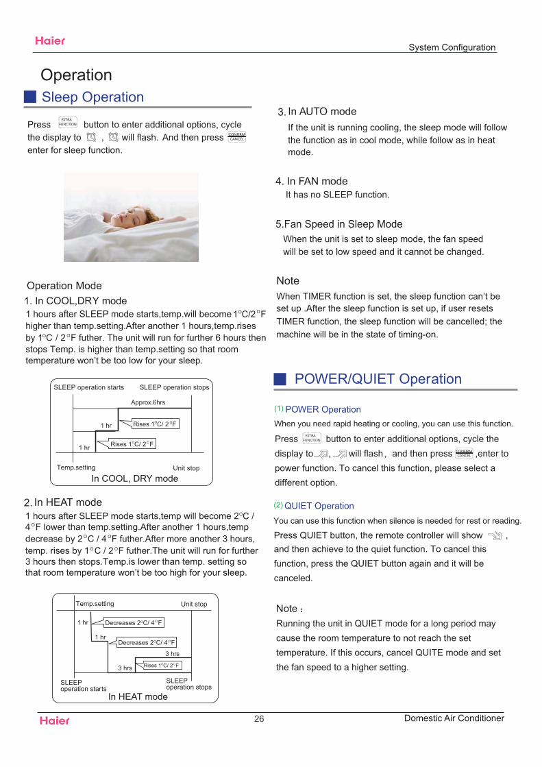
Operation Mode1. In COOL,DRY mode
SLEEP operation starts SLEEP operation stops
SLEEPoperation starts
SLEEPoperation stops
Approx.6hrs
1 hr
1 hr
1 hr
3 hrs
3 hrs
Rises 1OC/ 2 F
Rises 1OC/ 2 F
Rises 1OC/ 2 F
Temp.setting
Temp.setting
Unit stop
Unit stop
In COOL, DRY mode
In HEAT mode
Decreases 2OC/ 4 F
Decreases 2OC/ 4 F
1 hr
2. In HEAT mode
When TIMER function is set, the sleep function can’t be set up .After the sleep function is set up, if user resetsTIMER function, the sleep function will be cancelled; themachine will be in the state of timing-on.
1 hours after SLEEP mode starts,temp.will become higher than temp.setting.After another 1 hours,temp.risesby 1 / 2 F futher. The unit will run for further 6 hours then stops Temp. is higher than temp.setting so that roomtemperature won’t be too low for your sleep.
1 hours after SLEEP mode starts,temp will become 24 F lower than temp.setting.After another 1 hours,temp decrease by 2 C / 4 F futher.After more another 3 hours,temp. rises by 1 C / 2 F futher.The unit will run for further3 hours then stops.Temp.is lower than temp. setting sothat room temperature won’t be too high for your sleep.
If the unit is running cooling, the sleep mode will follow the function as in cool mode, while follow as in heat mode.
OC
O
O
1OC/2 F
OC /
Press button to enter additional options, cyclethe display to , will flash. And then pressenter for sleep function.
(1) POWER Operation
(2) QUIET Operation
Note
When you need rapid heating or cooling, you can use this function.
You can use this function when silence is needed for rest or reading.
Running the unit in QUIET mode for a long period may cause the room temperature to not reach the set temperature. If this occurs, cancel QUITE mode and set the fan speed to a higher setting.
Press QUIET button, the remote controller will show , and then achieve to the quiet function. To cancel this function, press the QUIET button again and it will be canceled.
Press button to enter additional options, cycle the display to , will flash,and then press ,enter to power function. To cancel this function, please select a different option.
O
O
O
O
O
O
O
O
O
O
System Configuration
26 Domestic Air Conditioner
Operation
1.After unit starts, select your desired operation mode.
2.Press TIMER button to change TIMER mode. Everytime the button is pressed, display changes as follows:
Remote controller:
Then select your desired TIMER mode (TIMER ON orTIMER OFF or TIMER ON-OFF). " "or " "will flash.
Timer On/Off On-Off Operation Healthy airflow Operation
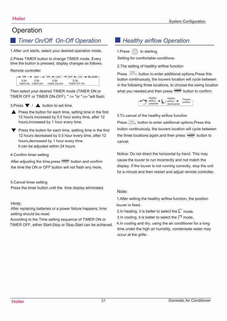
1.Press to starting
2.The setting of healthy airflow function
Note:
BLANK
TIMER ON TIMER OFF TIMER ON-OFF
3.Press / button to set time.
It can be adjusted within 24 hours.
Hints:After replacing batteries or a power failure happens, timesetting should be reset.According to the Time setting sequence of TIMER ON orTIMER OFF, either Start-Stop or Stop-Start can be achieved.
TIMER OFF-ON0.5h 0.5h 0.5h 0.5h
Press the button for each time, setting time in the first 12 hours increased by 0.5 hour every time, after 12 hours,increased by 1 hour every time.
Press the button for each time, settiing time in the first 12 hours decreased by 0.5 hour every time, after 12 hours,decreased by 1 hour every time.
4.Confirm timer setting
5.Cancel timer setting
Press button to enter additional options,Press this button continuously, the louvers location will cycle between in the following three locations, to choose the swing location what you needed,and then press button to confirm.
Healthyairflowupwarder
Healthyairflowdownwarder
Presentposition
Setting for comfortable conditions.
1.After setting the healthy airflow function, the position louver is fixed.
4.In cooling and dry, using the air conditioner for a long time under the high air humidity, condensate water mayoccur at the grille .
3.To cancel of the healthy airflow function
Notice: Do not direct the horizontal by hand. This maycause the louver to run incorrectly and not match thedisplay. If the louver is not running correctly, stop the unitfor a minute and then restart and adjust remote controller.
2.In heating, it is better to select the3.In cooling, it is better to select the
mode.mode.
After adjusting the time,press button and confirmthe time the ON or OFF button will not flash any more.
Press the timer button until the time display eliminated.
Press button to enter additional options,Press this
button continuously, the louvers location will cycle between
the three locations again,and then press button tocancel.
System Configuration
27 Domestic Air Conditioner
Maintenance
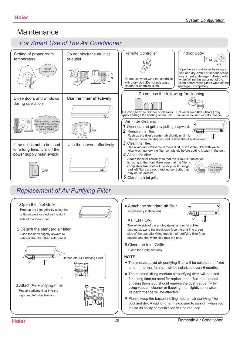
Setting of proper roomtemperature
Close doors and windowsduring operation
If the unit is not to be usedfor a long time, turn off thepower supply main switch.
Use the timer effectively
Use the louvers effectively
Do not block the air inletor outlet
Propertemperature
During cooling operationprevent the penetration of direct sunlight with
curtain or blind
OFF
Remote Controller Indoor Body
1.Open the lnlet Grille
2.Detach the standard air filter
3.Attach Air Purifying Filter
4.Attach the standard air filter(Necessary installation)
5.Close the Inlet Grille
Slide the knob slightly upward to release the filter, then withdraw it.
Detach old Air Purifying Filter NOTE:The photocatalyst air purifying filter will be solarized in fixedtime. In normal family, it will be solarized every 6 months.
ATTENTION:
For Smart Use of The Air Conditioner
Replacement of Air Purifying Filter
The white side of the photocatalyst air purifying filter face outside,and the black side face the unit The green side of the bacteria-killing medium air purifying filter face outside,and the white side face the unit.
Do not usewater,wipe the controllerwith a dry cloth.Do not use glasscleaner or chemical cloth.
wipe the air conditioner by using a soft and dry cloth.For serious stains,use a neutral detergent diluted withwater.Wring the water out of the cloth before wiping,then wipe off the detergent completely.
Air Filter cleaningOpen the inlet grille by pulling it upward.Remove the filter.
Clean the filter.
Attach the filter.
Close the inlet grille.
Push up the filter's center tab slightly until it is from the stopper, and remove the filter downward.
Attach the filter correctly so that the "FRONT" indicationfacing to the front.Make sure that the filter is
fixed behind the stopper.If the rightattached correctly, that
Do not use the following for cleaning
Gasoline,benzine, thinner or cleanseray damage the coating of the unit.
Hot water over 40OC(104OF) maydiscoloring or deformation.
Once everytwo weeks
m cause
released
iscompletelyand left filters are notmay cause defects.
Close the Grille securely
Put air purifying filter into theright and left filter frames.
Prop up the inlet grille by using the grille-support located an the right
Please keep the bacteria-killing medium air purifying filter
its ability of sterilization will be reduced.
The bacteria-killing medium air purifying filter will be used for a long time,no need for replacement. But in the period of using them ,you should remove the dust frequently by
side of the indoor unit.
using vacuum cleaner or flapping them lightly,otherwise ,its performance will be affected.
cool and dry. Avoid long term exposure to sunlight when not in use
Use a vacuum cleaner to remove dust, or wash the filter with water. After washing, dry the filter completely before putting it back in the unit.
System Configuration
28 Domestic Air Conditioner
the power supply cordand so on.
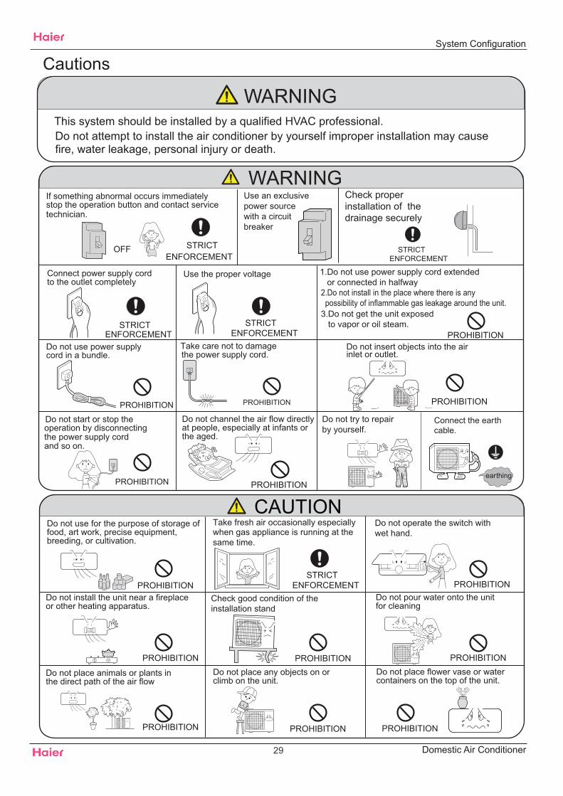
2.Do not install in the place where there is any possibility of inflammable gas leakage around the unit.3.Do not get the unit exposed to vapor or oil steam.
Cautions
Connect the earthcable.
earthing
WARNING
OFF
Use an exclusive power sourcewith a circuit breaker
ENFORCEMENT
Connect power supply cordto the outlet completely
Use the proper voltage
Do not use power supply cord in a bundle.
Take care not to damagethe power supply cord.
1.Do not use power supply cord extended or connected in halfway
STRICTENFORCEMENT
STRICT
STRICTENFORCEMENT PROHIBITION
PROHIBITION PROHIBITION
PROHIBITION
Do not start or stop theoperation by disconnecting
Do not channel the air flow directlyat people, especially at infants orthe aged.
Do not use for the purpose of storage offood, art work, precise equipment,breeding, or cultivation.
CAUTIONTake fresh air occasionally especiallywhen gas appliance is running at thesame time.
PROHIBITIONSTRICT
ENFORCEMENT
Do not operate the switch withwet hand.
PROHIBITION
PROHIBITION
PROHIBITION PROHIBITION
PROHIBITION
Do not install the unit near a fireplaceor other heating apparatus.
Check good condition of theinstallation stand
Do not pour water onto the unitfor cleaning
PROHIBITION
Do not place animals or plants inthe direct path of the air flow
Do not place any objects on orclimb on the unit.
Do not place flower vase or watercontainers on the top of the unit.
Do not insert objects into the airinlet or outlet.
PROHIBITION
PROHIBITION
PROHIBITION
STRICTENFORCEMENT
Check properinstallation of thedrainage securely
WARNING
If something abnormal occurs immediatelystop the operation button and contact servicetechnician.
Do not try to repair by yourself.
Do not attempt to install the air conditioner by yourself improper installation may cause This system should be installed by a qualified HVAC professional.
fire, water leakage, personal injury or death.
System Configuration
29 Domestic Air Conditioner
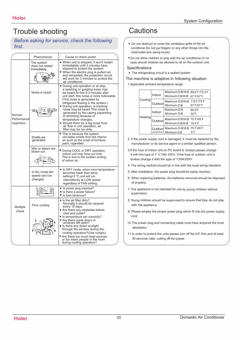
Trouble shooting
NormalPerformanceinspection
Noise is heard
Phenomenon Cause or check points
The system
immediately.
Smells aregenerated.
Mist or steam are
Multiplecheck
Poor cooling
When unit is stopped, it won't restart
elapsed to protect the system.When the electric plug is pulled out and reinserted, the protection circuit
During unit operation or at stop, a swishing or gurgling noise may
(This noise is generated byrefrigerant flowing in the system.)During unit operation, a crackingnoise may be heard.This noise is
temperature changes.Should there be a big noise from
filter may be too dirty.This is because the system circulates smells from the interior
During COOL or DRY operation,
This is due to the sudden cooling
Is power plug inserted?Is there a power failure?Is fuse blownout?Is the air filter dirty?
Are there any obstacles before
Is temperature set correctly?Are there some doors or
Is there any direct sunlightthrough the window during the
Are there too much heat sourcesor too many people in the room
In dry mode, fan speed can’t be changed.
In DRY mode, when room temperature
setting+2 oC,unit will run
regardless of FAN setting.
during cooling operation?
cooling operation?(Use curtain)
windows left open?
inlet and outlet?
Normally it should be cleaned every 15 days.
intermittently at LOW speed
becomes lower than temp.
indoor unit may blow out mist.
of indoor air.
air such as the smell of furniture,paint, cigarettes.
air flow in unit operation, air
generated by the casing expandingor shrinking because of
be heard.At first 2-3 minutes afterunit start, this noise is more noticeable.
will work for 3 minutes to protect theair conditioner.
immediately until 3 minutes have
Cautions
3. If the fuse of indoor unit on PC board isit with the type of T. 3.15A/ 250V outdoor
broken,change it with the type of T.25A/250V
Do not obstruct or cover the ventilationconditoner.Do not put fingersinlet/outlet and swing louver.
Do not allow children to play with the air conditionercase should children be allowed to sit on the outdoor unit.
The refrigerating circuit is a sealed system.
1.Applicable ambient temperature range:
Specifications
The machine is adaptive in following situation
The power plug and connecting cable acquired the local
2. If the power supply cord is damaged, it must be replaced manufacturer qualified person.
4. The wiring method should be in line with the local wiring
5. After installation, the power plug should be easily reached.
8.Young children should be supervisedwith the appliance.
9. Please employ the proper power plug,cord.
11.In order to protect the units,please turn30 seconds later, cutting off the power.
10.
grille of the air or any other things into the
.In no
or its service agent or a similar
broken,please. If the fuse of
standard.
to ensure that they
which fit into the
must have
off the A/C first,
Before asking for service, check the following first.
blown out.
does not restart
by the
changeunit is
do not play
power supply
attestation.
and at least
CoolingIndoor
Maximum:D.B/W.B
Maximum:D.B/W.BD.B
Maximum:D.BD.B
Minimum:D.B/W.B
Maximum:D.B/W.BMinimum:D.B/W.B
Outdoor
Indoor
OutdoorHeating
89.6 /73.4
75 /65
115 /75
80.6
67 /57
Outdoor Maximum:D.B/W.BMinimum:D.B 5(INVERTER)
32
Minimum:
Minimum:
67 /57
75 /65
19.4
6. When replacing batteries, the batteries removed should be disposed of properly.
7. The appliance is not intended for usesupervision.
by young children without
System Configuration
30 Domestic Air Conditioner
Functions and control
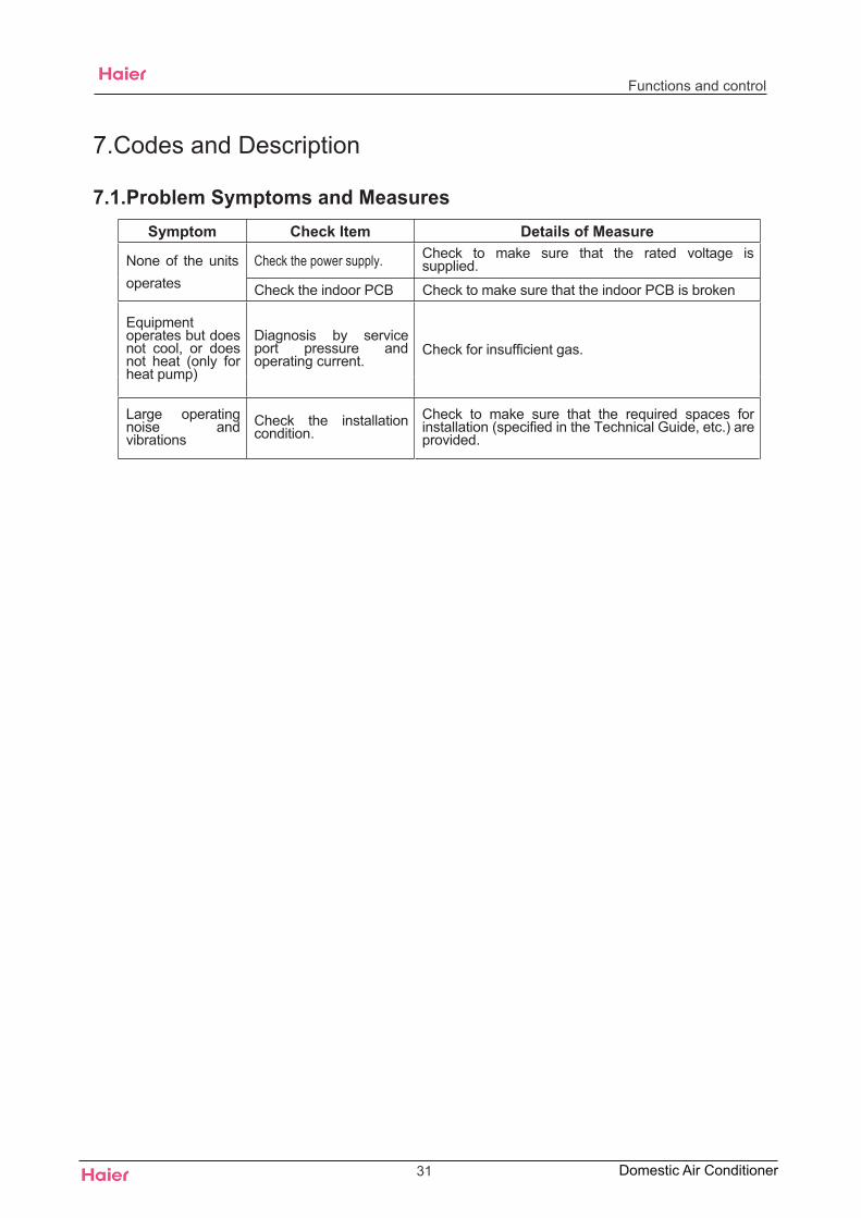
7.Codes and Description
7.1.Problem Symptoms and MeasuresSymptom Check Item Details of Measure
Check the power supply. Check to make sure that the rated voltage issupplied.None of the units
operates Check the indoor PCB Check to make sure that the indoor PCB is broken
Equipmentoperates but doesnot cool, or doesnot heat (only forheat pump)
Diagnosis by serviceport pressure andoperating current.
Check for insufficient gas.
Large operatingnoise andvibrations
Check the installationcondition.
Check to make sure that the required spaces forinstallation (specified in the Technical Guide, etc.) areprovided.
31 Domestic Air Conditioner
Codes and description
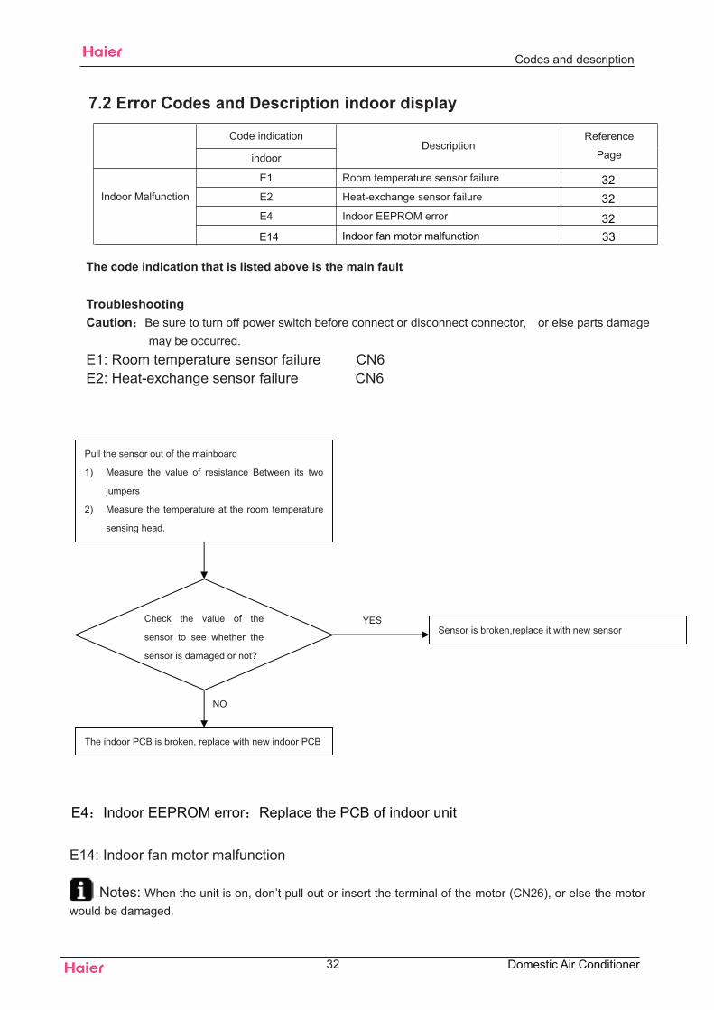
7.2 Error Codes and Description indoor display
Code indication
indoorDescription
Reference
Page
E1 Room temperature sensor failure
eruliafrosnesegnahcxe-taeH2EIndoor Malfunction
rorreMORPEEroodnI4E
The code indication that is listed above is the main fault
TroubleshootingCaution Be sure to turn off power switch before connect or disconnect connector, or else parts damage
may be occurred.E1: Room temperature sensor failure CN6E2: Heat-exchange sensor failure CN6
NO
Check the value of the
sensor to see whether the
sensor is damaged or not?
YES
The indoor PCB is broken, replace with new indoor PCB
Sensor is broken,replace it with new sensor
Pull the sensor out of the mainboard
1) Measure the value of resistance Between its two
jumpers
2) Measure the temperature at the room temperature
sensing head.
32 Domestic Air Conditioner
3232
33E14 Indoor fan motor malfunction32
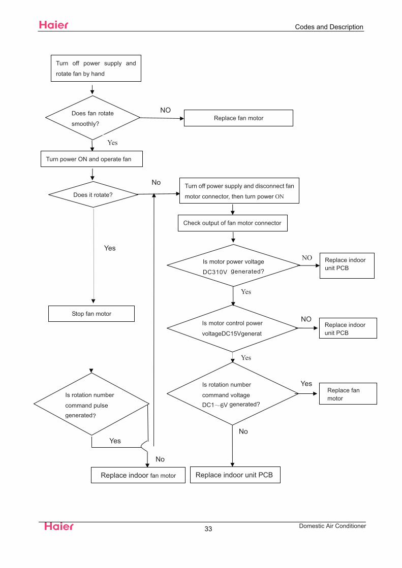
E14: Indoor fan motor malfunction
Notes: When the unit is on, don’t pull out or insert the terminal of the motor (CN26), or else the motorwould be damaged.
E4 Indoor EEPROM error Replace the PCB of indoor unit
Domestic Air Conditioner
NO
Yes
Does fan rotate
smoothly?
NOReplace fan motor
Yes
Turn power ON and operate fan
Does it rotate?
No
Yes
Turn off power supply and disconnect fan
motor connector, then turn power ON
Check output of fan motor connector
Is motor power voltage
DC310V generated?
Yes
NO
Yes
NoYes
Stop fan motorIs motor control power
voltageDC15Vgenerat
Is rotation number
command voltageDC1 6V generated?
Replace indoor unit PCB
No
Replace indoor fan motor
Turn off power supply and
rotate fan by hand
Replace indoorunit PCB
Replace indoorunit PCB
Replace fanmotorIs rotation number
command pulsegenerated?
Codes and Description
33
Capacity
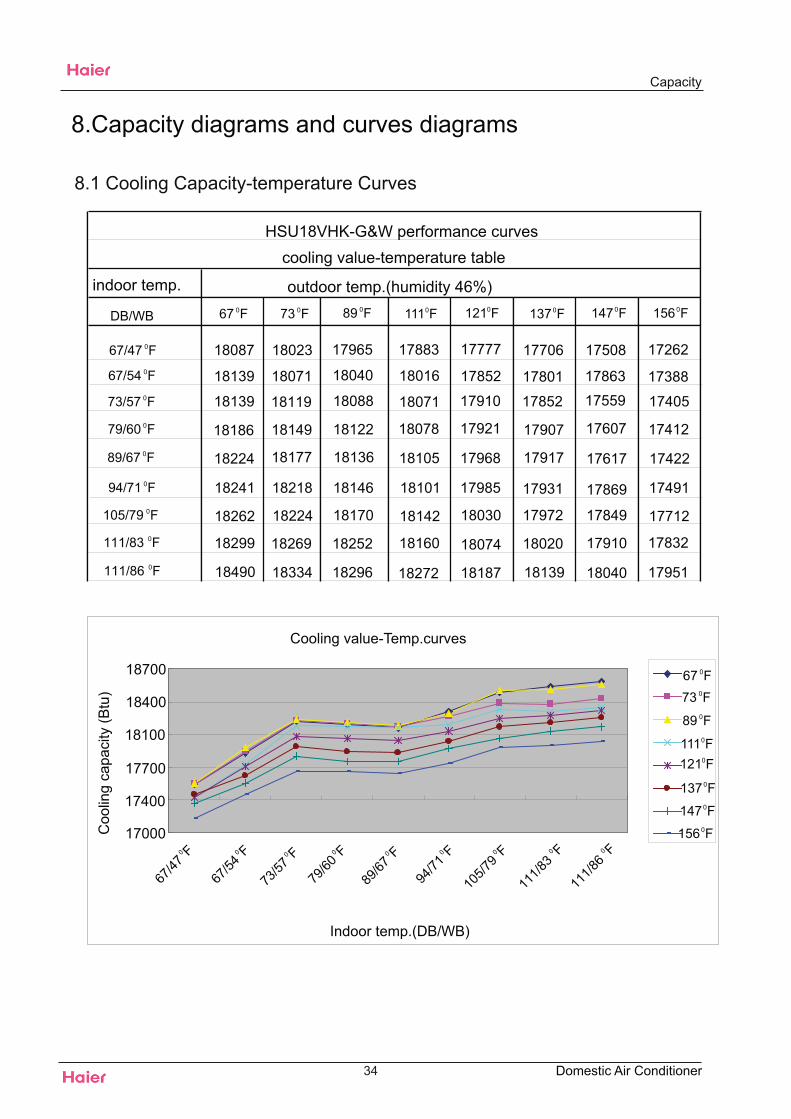
8.1 Cooling Capacity-temperature Curves
34
17000
17400
17700
18100
18400
18700
cooling value-temperature table
indoor temp. outdoor temp.(humidity 46%)
8.Capacity diagrams and curves diagrams
18087 18023 17965 17883 17777 17706 17508 17262
18139 18071 18040 18016 17852 17801 17863 17388
18139 18119 18088 18071 17910 17852 17559 17405
18186 18149 18122 18078 17921 17907 17607 17412
18224 18177 18136 18105 17968 17917 17617 17422
18241 18218 18146 18101 17985 17931 17869 17491
18262 18224 18170 18142 18030 17972 17849 17712
18299 18269 18252 18160 18074 18020 17910 17832
18490 18334 18296 18272 18187 18139 18040 17951
Indoor temp.(DB/WB)
Coo
ling
capa
city
(Btu
)
Cooling value-Temp.curves
DB/WB
Domestic Air Conditioner
67 0F 73 0F 89 0F 1110F 1210F 1370F 1470F 1560F
67/47 0F
67/54 0F
73/57 0F
79/60 0F
89/67 0F
94/71 0F
105/79 0F
111/83 0F
111/86 0F
67/47
0 F
67/54
0 F
73/57
0 F
79/60
0 F
89/67
0 F
94/71
0 F
105/7
90 F
111/8
30 F
111/8
60 F
67 0F73 0F
89 0F
1110F1210F
1370F
1470F
1560F
HSU18VHK-G&W performance curves
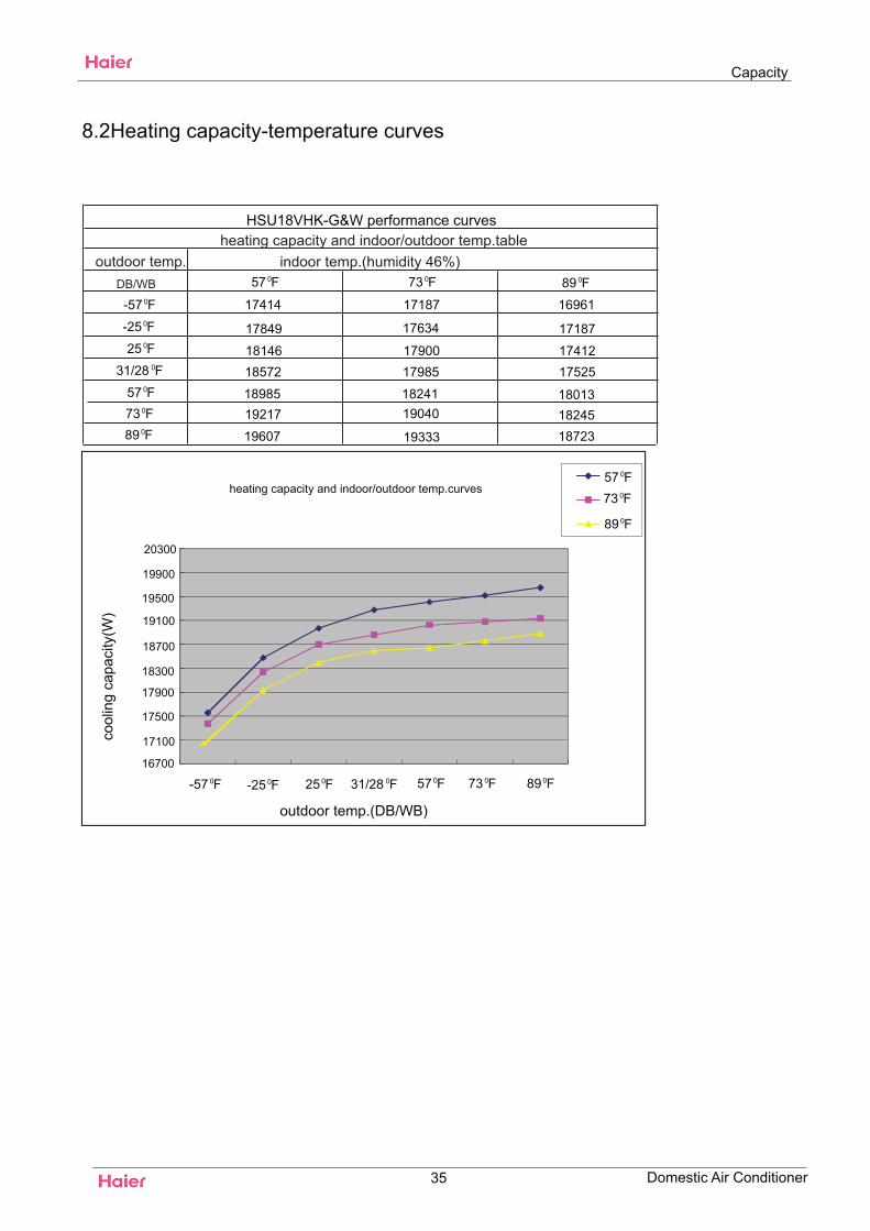
8.2Heating capacity-temperature curves
outdoor temp.DB/WB
indoor temp.(humidity 46%)heating capacity and indoor/outdoor temp.table
35
HSU18VHK-G&W performance curves
heating capacity and indoor/outdoor temp.curves
outdoor temp.(DB/WB)
cool
ing
capa
city
(W)
16700
17100
17500
17900
18300
18700
19100
19500
19900
Capacity
Domestic Air Conditioner
0F57 0F73 0F890F-570F-250F25
0F31/280F570F730F89
0F570F730F89
0F-57 0F-25 0F25 0F31/28 0F57 0F73 0F89
17414
17849
1814618572
1898519217
19607
17187
17634
1790017985
1824119040
19333
16961
17187
1741217525
180131824518723
20300
DB/WB
Power consumption-temp curves
Capacity
36
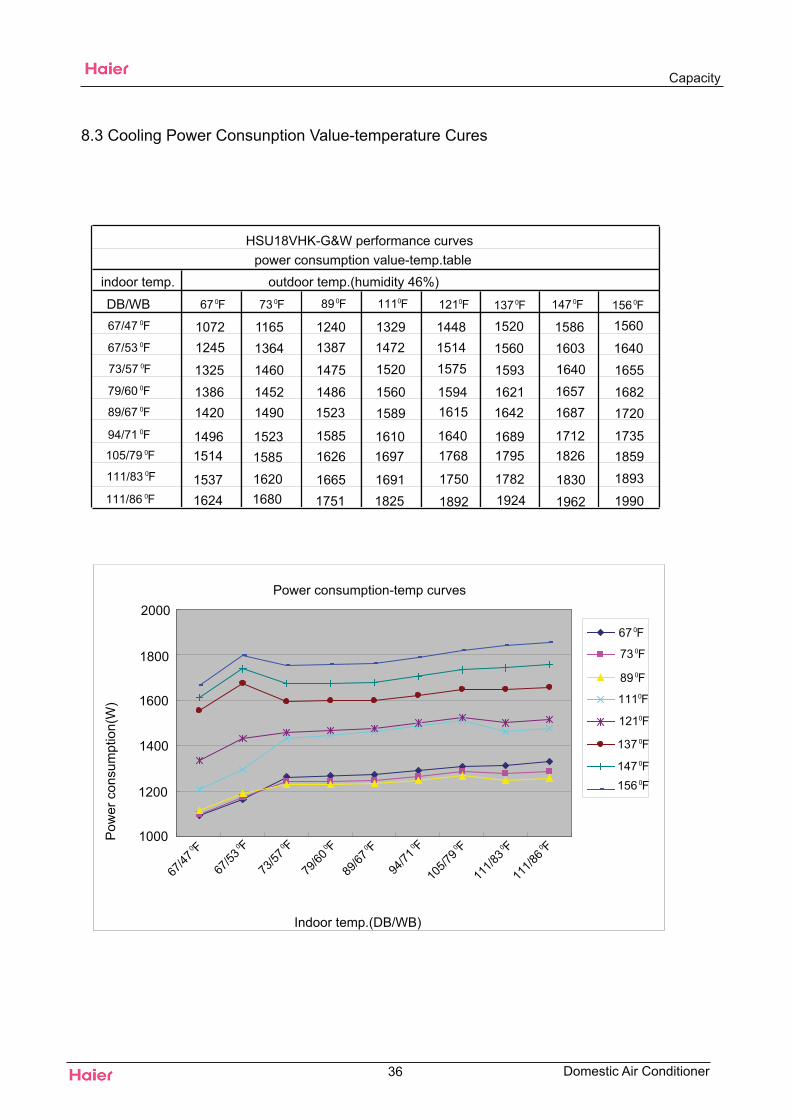
HSU18VHK-G&W performance curvespower consumption value-temp.table
indoor temp. outdoor temp.(humidity 46%)
Indoor temp.(DB/WB)
1000
1200
1400
1600
1800
2000
1072 1165 1240 1329 1448 1520 1586 15601245 1364 1387 1472 1514 1560 1603 16401325 1460 1475 1520 1575 1593 1640 16551386 1452 1486 1560 1594 1621 1657 16821420 1490 1523 1589 1615 1642 1687 1720
1496 1523 1585 1610 1640 1689 1712 17351514 1585 1626 1697 1768 1795 1826 1859
1537 1620 1665 1691 1750 1782 1830 18931624 1680 1751 1825 1892 1924 1962 1990
8.3 Cooling Power Consunption Value-temperature CuresP
ower
con
sum
ptio
n(W
)
Domestic Air Conditioner
0F67 0F73 0F89 0F111 0F121 0F137 0F147 0F1560F67/470F67/530F73/570F79/600F89/670F94/71
0F105/790F111/830F111/86
0F670F730F890F1110F1210F1370F1470F156
0 F
67/47
0 F
67/53
0 F
73/57
0 F
79/60
0 F
89/67
0 F
94/71
0 F
105/7
90 F
111/8
30 F
111/8
6
Capacity
HSU18VHK-G&W performance curves
outdoor temp indoor temp.(humidity 46%)
37
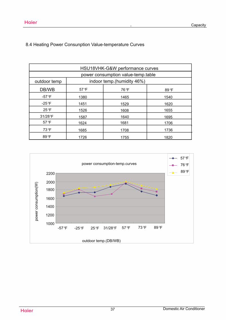
1380 1465 1540
1451 1529 16201526 1608 1655
1587 1640 16951624 1681 1706
1685 1708 1736
1726 1755 1820
outdoor temp.(DB/WB)
pow
er c
onsu
mpt
ion(
W)
power consumption-temp.curves
1000
1200
1400
1600
1800
2000
2200
8.4 Heating Power Consunption Value-temperature Curves
power consumption value-temp.table
DB/WB
Domestic Air Conditioner
0F57 0F76 0F890F-570F-250F25
0F31/280F570F730F89
0F570F760F89
0F-57 0F-25 0F25 0F31/28 0F57 0F73 0F89
HSU18VHK-G&W
208~230V,60HZ
3
Sound level
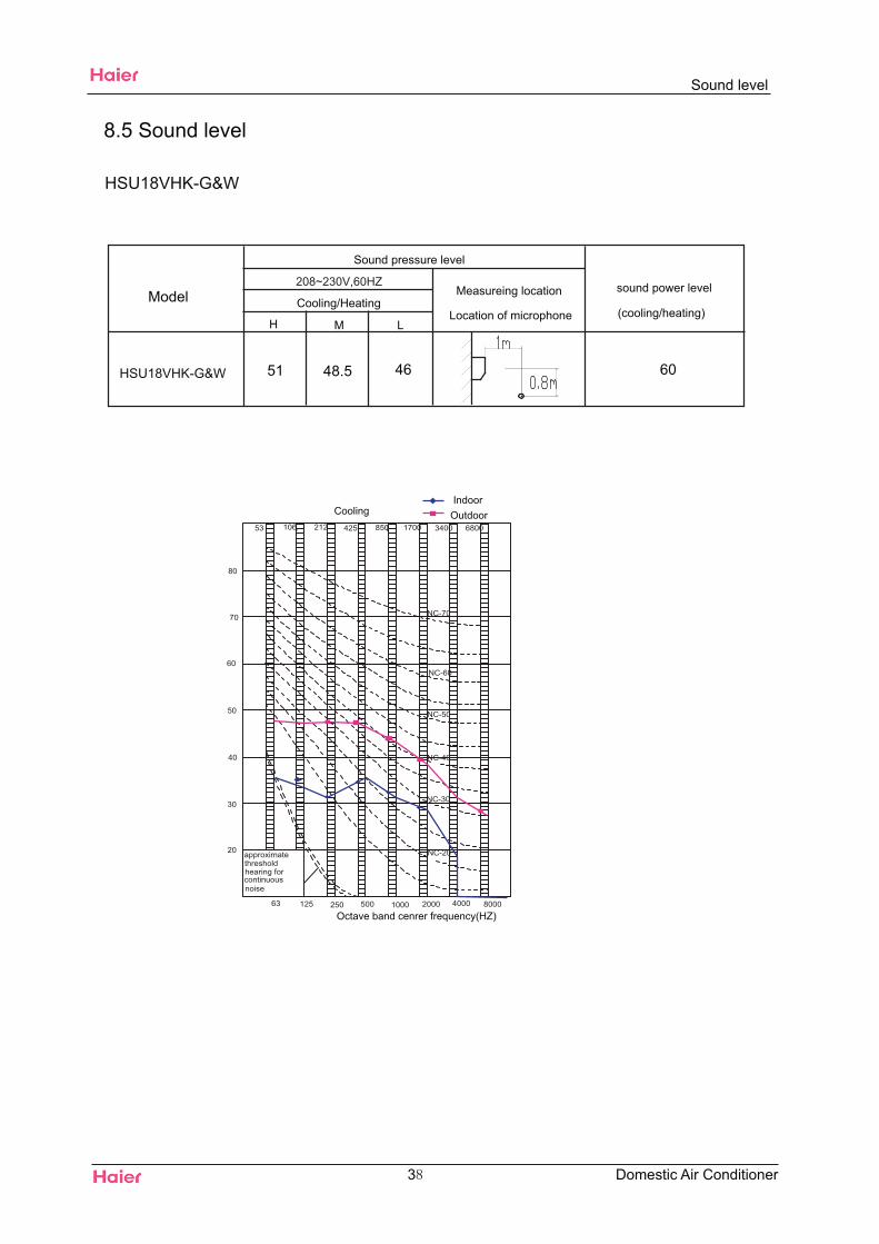
8.5 Sound level
H M L
Sound pressure level
Cooling/HeatingMeasureing location
Location of microphone
sound power level
(cooling/heating)
Octave band cenrer frequency(HZ)
CoolingIndoor
Outdoor
Model
Domestic Air Conditioner
51 48.5 46 60HSU18VHK-G&W
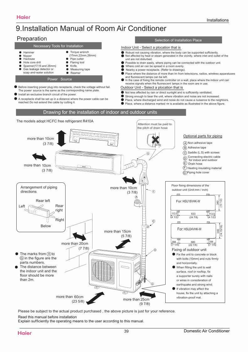
Drawing for the installation of indoor and outdoor units
Necessary Tools for Installation
Hammer Torque wrench(17mm,22mm,26mm)Nipper
Reamer
Hacksaw Pipe cutter
Gas leakage detector orsoap-and-water solution
Hole core drill Flaring toolSpanner(17,19 and 26mm) Knife
Measuring tapePlace where the distance of more than lm from televisions, radios, wireless apparatusesand fluorescent lamps can be left.In the case of fixing the remote controller on a wall, place where the indoor unit canreceive signals when the fluorescent lamps in the room are in use.
Place, where discharged wind and noise do not cause a nuisance to the neighbors.Place, where a distance marked � is available as illustrated in the above figure.
Before inserting power plug into receptacle, check the voltage without fail.The power source is the same as the corresponding name plate.Install an exclusive branch circuit of the power.A receptacle shall be set up in a distance where the power cable can bereached.Do not extend the cable by cutting it.
Selection of Installation Place
Power Source
The models adopt HCFC free refrigerant R410A
Indoor Unit - Select a plocation that is
Outdoor Unit - Select a plocation that is
Robust not causing vibration, where the body can be supported sufficiently.Not affected by heat or steam generated in the vicinity, where inlet and outlet of the unit are not disturbed.Possible to drain easily, where piping can be connected with the outdoor unit.Where cold air can be spread in a room evenly.Nearby a power receptacle. (Refer to drawings).
Not less affected by rain or direct sunlight and is sufficiently ventilated.Strong enough to bear the unit, where vibration and noise are not increased.
Please be subject to the actual product purchased , the above picture is just for your reference.Read this manual before installationExplain suf ciently the operating means to the user according to this manual.
Optional parts for piping
Non-adhesive tapeAdhesive tape
Saddle (L.S) with screwsConnecting electric cablefor indoor and outdoorDrain hoseHeating insulating materialPiping hole cover
Floor xing dimensions of theoutdoor unit (Unit:mm / inch)
Fixing of outdoor unitFix the unit to concrete or blockwith bolts (10mm) and nuts rmlyand horizontally.When tting the unit to wallsurface, roof or rooftop, xa supporter surely with nailsor wires in consideration of earthquake and strong wind.If vibration may affect thehouse, x the unit by attaching avibration-proof mat.
The marks from toin the gure are the
parts numbers.The distance betweenthe indoor unit and theoor should be more
than 2m.
more than 10cm
more than 10cm
more than 10cm
more than 20cm
more than 15cm
more than 25cmmore than 60cm
AG
A
F
C
ED
G
B
Arrangement of pipingdirections
Rear leftLeft Rear
right
Right
Below
Attention must be paid tothe pitch of drain hose
A
C
184 580 184
083
For:
(3 7/8)
(3 7/8)
(3 7/8)
(7 7/8)
(23 5/8)(9 7/8)
(5 7/8)
(4 1/2)
For:
(24 7/8) (4 1/2)(1
3 1/
2)
113.5 113.5633
340
(14
15/1
6)
(7 1/4)(22 7/8)(7 1/4)
HSU18VHK-W
HSU24VHK-W
Installations
Preparation9.Installation Manual of Room Air Conditioner
39 Domestic Air Conditioner
Indoor unit
Fix to side bar and lintel a mounting bar, Which is separately sold, and thenfasten the plate to the fixed mounting bar.
Refer to the previous article, “ When the mounting plate isposition of wall hole.
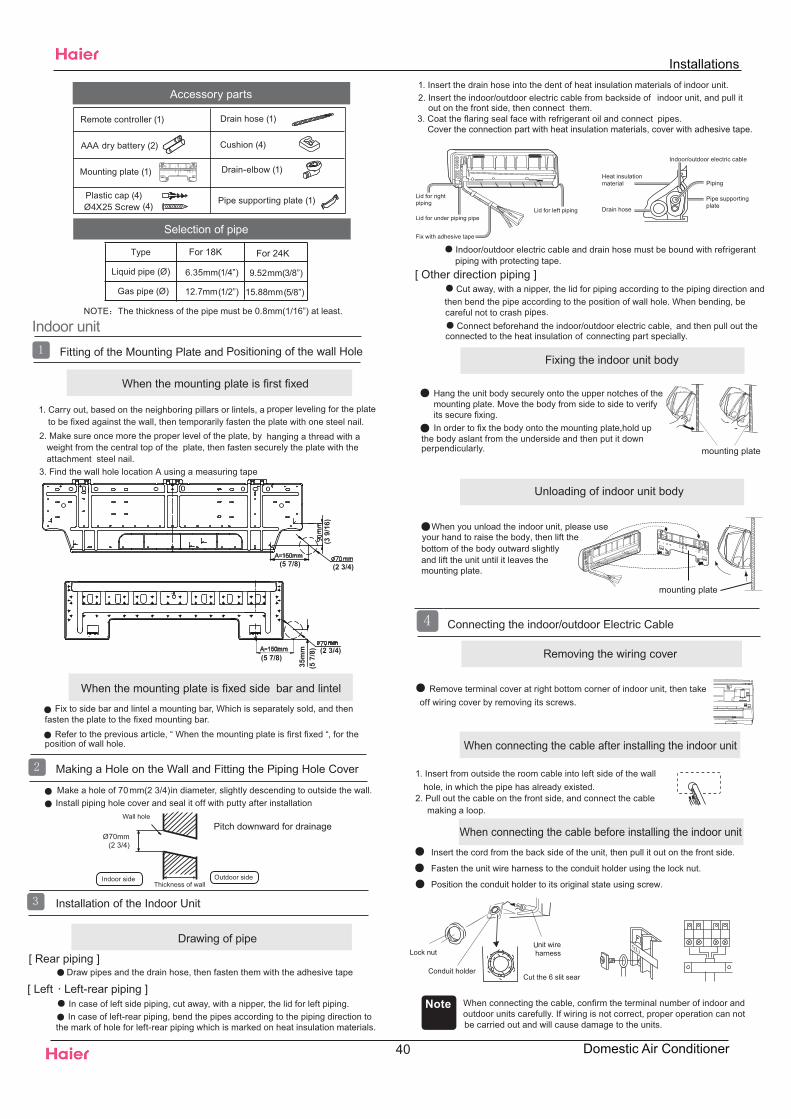
Make a hole of 70mm(2 3/4)in diameter, slightly descending to outside the wall.Install piping hole cover and seal it off with putty after installation
When the mounting plate is first fixed
1. Carry out, based on the neighboring pillars or lintels, a to be fixed against the wall, then temporarily fasten the plate with one steel nail.
2. Make sure once more the proper level of the plate, by hanging a thread with a weight from the central top of the plate, then fasten securely the plate with theattachment steel nail.
3. Find the wall hole location A using a measuring tape
When the mounting plate is fixed side bar and lintel
Fitting of the Mounting Plate and Positioning of the wall Hole
Lid for rightpiping
Lid for under piping pipe
Fix with adhesive tape
Lid for left piping
Indoor/outdoor electric cable and drain hose must be bound with refrigerant
[ Other direction piping ]Cut away, with a nipper, the lid for piping according to the piping direction and
then bend the pipe according to the position of wall hole. When bending, becareful not to crash pipes.
Connect beforehand the indoor/outdoor electric cable, and then pull out theconnected to the heat insulation of connecting part specially.
proper leveling for the plate
first fixed “, for the
Making a Hole on the Wall and Fitting the Piping Hole Cover
Drawing of pipe
Installation of the Indoor Unit
[ Rear piping ]Draw pipes and the drain hose, then fasten them with the adhesive tape
[ Left·Left-rear piping ]In case of left side piping, cut away, with a nipper, the lid for left piping.In case of left-rear piping, bend the pipes according to the piping direction to
the mark of hole for left-rear piping which is marked on heat insulation materials.
1. Insert the drain hose into the dent of heat insulation materials of indoor unit.2. Insert the indoor/outdoor electric cable from backside of indoor unit, and pull it
out on the front side, then connect them.3. Coat the flaring seal face with refrigerant oil and connect pipes.
Fixing the indoor unit body
In order to fix the body onto the mounting plate,hold upthe body aslant from the underside and then put it downperpendicularly.
Connecting the indoor/outdoor Electric Cable
Removing the wiring cover
Remove terminal cover at right bottom corner of indoor unit, then take off wiring cover by removing its screws.
1. Insert from outside the room cable into left side of the wallhole, in which the pipe has already existed.
2. Pull out the cable on the front side, and connect the cablemaking a loop.
Note When connecting the cable, confirm the terminal number of indoor andoutdoor units carefully. If wiring is not correct, proper operation can notbe carried out and will cause damage to the units.
mounting plate
When connecting the cable after installing the indoor unit
When connecting the cable before installing the indoor unit
When you unload the indoor unit, please use
bottom of the body outward slightlyand lift the unit until it leaves themounting plate.
mounting plate
Unloading of indoor unit body
your hand to raise the body, then lift the
Remote controller (1)
AAA dry battery (2)
Mounting plate (1)
Drain hose (1)
Ø4X25 Screw (4)Plastic cap (4)
Drain-elbow (1)
Cushion (4)
Pipe supporting plate (1)
Accessory parts
NOTE The thickness of the pipe must be 0.8mm(1/16”) at least.
Selection of pipe
Insert the cord from the back side of the unit, then pull it out on the front side.
Fasten the unit wire harness to the conduit holder using the lock nut.
Position the conduit holder to its original state using screw.
Conduit holderCut the 6 slit sear
Cover the connection part with heat insulation materials, cover with adhesive tape.
piping with protecting tape.
Hang the unit body securely onto the upper notches of themounting plate. Move the body from side to side to verify its secure fixing.
Indoor side Outdoor side
Ø70mm
Wall hole
Thickness of wall
Heat insulationmaterial
Drain hose
Piping
Pipe supportingplate
Indoor/outdoor electric cable
mm
mm
A=150mm
A=150mmmm
35m
m
Liquid pipe (Ø)
Gas pipe (Ø)
For 18K
6.35mm(1/4”)
12.7mm(1/2”)
Type For 24K
9.52mm(3/8”)
15.88mm(5/8”)
(5 7/8)
(5 7/8)
(5 7
/8) (2 3/4)
(2 3/4)
Pitch downward for drainage
(2 3/4)
(3 9
/16)
Installations
40 Domestic Air Conditioner
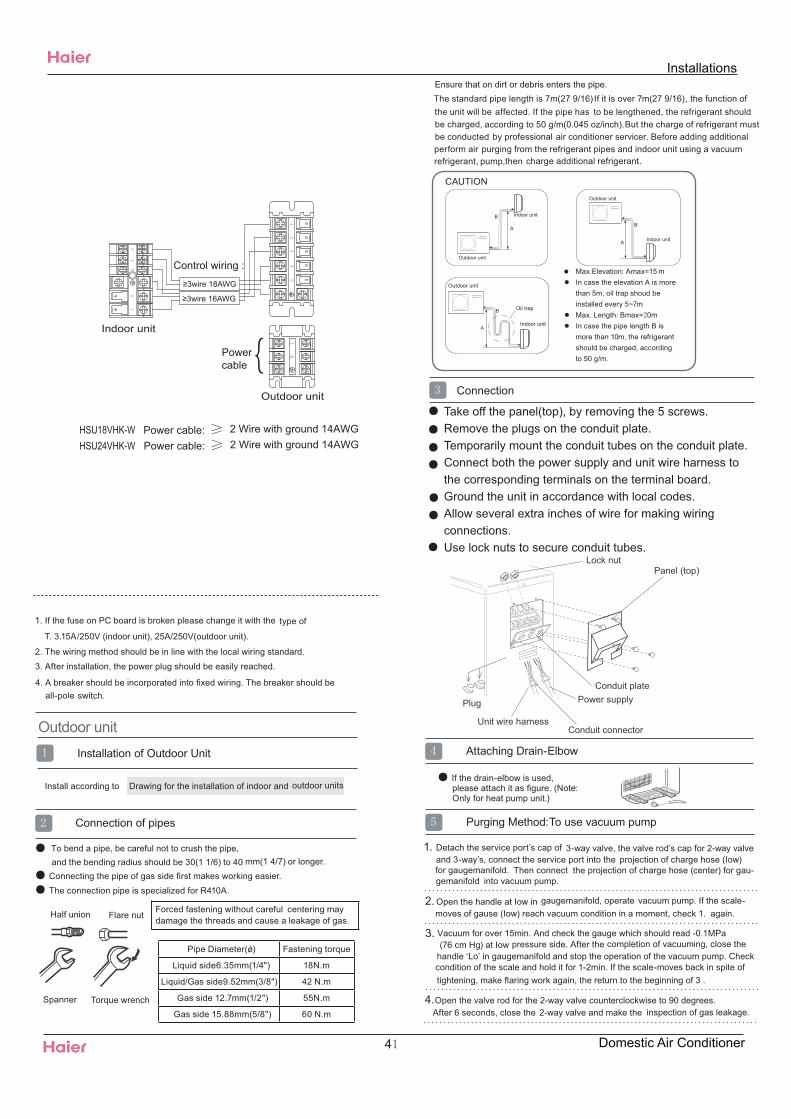
1. If the fuse on PC board is broken please change it with the type of
T. 3.15A/250V (indoor unit), 25A/250V(outdoor unit).
2. The wiring method should be in line with the local wiring standard.3. After installation, the power plug should be easily reached.
4. A breaker should be incorporated into fixed wiring. The breaker should beall-pole switch.
Outdoor unit
Install according to Drawing for the installation of indoor and outdoor units
and the bending radius should be 30(1 1/6) to 40 mm(1 4/7) or longer.Connecting the pipe of gas side first makes working easier.The connection pipe is specialized for R410A.
Installation of Outdoor Unit
Half union Flare nut
Torque wrench
The standard pipe length is 7m(27 9/16). If it is over 7m(27 9/16), the function ofthe unit will be affected. If the pipe has to be lengthened, the refrigerant shouldbe charged, according to 50 g/m(0.045 oz/inch).But the charge of refrigerant mustbe conducted by professional air conditioner servicer. Before adding additional
refrigerant,perform air purging from the refrigerant pipes and indoor unit using a vacuum
pump,then
Spanner
Forced fastening without careful centering maydamage the threads and cause a leakage of gas.
Pipe Diameter(ǿ) Fastening torque
Liquid side6.35mm(1/4") 18N.m
Liquid/Gas side9.52mm(3/8") 42 N.m
Gas side 12.7mm(1/2") 55N.m
Gas side 15.88mm(5/8") 60 N.m
Connection of pipes
charge additional refrigerant.
Outdoor unit
Indoor unit
A
B
Outdoor unit
Indoor unitA
B
A
B
Outdoor unit
Indoor unit
Oil trap
CAUTION
Max.Elevation: Amax=15 m●In case the elevation A is more●than 5m, oil trap shoud beinstalled every 5~7mMax. Length: Bmax= 0m●In case the pipe length B is●more than 10m, the refrigerantshould be charged, accordingto 50 g/m.
Connection
If the drain-elbow is used,please attach it as figure. (Note:Only for heat pump unit.)
Detach the service port’s cap of1. 3-way valve, the valve rod’s cap for 2-way valveand 3-way’s, connect the service port into the projection of charge hose (Iow)for gaugemanifold. Then connect the projection of charge hose (center) for gau-gemanifold into vacuum pump.
Open the handle at Iow in2. gaugemanifold, operate vacuum pump. If the scale-moves of gause (Iow) reach vacuum condition in a moment, check 1. again.
3.(76 cm Hg) at Iow pressure side. After the completion of vacuuming, close the
handle ‘Lo’ in gaugemanifold and stop the operation of the vacuum pump. Checkcondition of the scale and hold it for 1-2min. If the scale-moves back in spite oftightening, make flaring work again, the return to the beginning of 3 .
Attaching Drain-Elbow
Purging Method:To use vacuum pump
Open the valve rod for the 2-way valve counterclockwise to 90 degrees.4.After 6 seconds, close the 2-way valve and make the inspection of gas leakage.
Take off the panel(top), by removing the 5 screws. Remove the plugs on the conduit plate.Temporarily mount the conduit tubes on the conduit plate.Connect both the power supply and unit wire harness tothe corresponding terminals on the terminal board.Ground the unit in accordance with local codes.Allow several extra inches of wire for making wiringconnections.Use lock nuts to secure conduit tubes.
To bend a pipe, be careful not to crush the pipe,
Ensure that on dirt or debris enters the pipe.
Vacuum for over 15min. And check the gauge which should read -0.1MPa
Power cable: 2 Wire with ground 14AWG
Indoor unit
Outdoor unit
Power cable:
Powercable
2 Wire with ground 14AWG
Control wiring :
≥3wire 18AWG
≥3wire 16AWG
HSU18VHK-WHSU24VHK-W
Installations
4 Domestic Air Conditioner
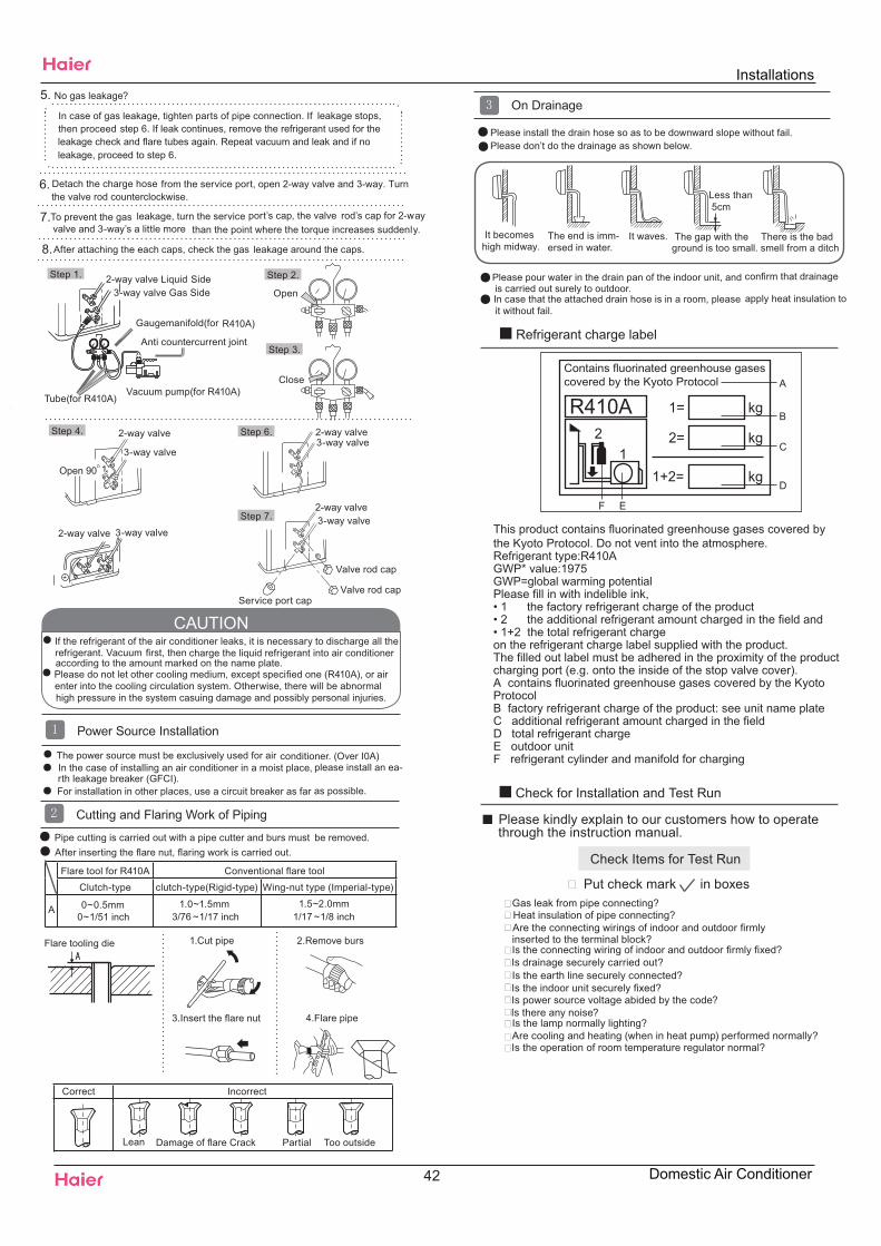
Open
No gas leakage?5.
Detach the charge hose6. from the service port, open 2-way valve and 3-way. Turn
Anti countercurrent joint
Gaugemanifold(for R410A)
2-way valve Liquid Side3-way valve Gas Side
Vacuum pump(for R410A)Tube(for R410A)
Close
2-way valve
3-way valve
Open 90O
2-way valve3-way valve
2-way valve 3-way valve
2-way valve3-way valve
Valve rod cap
Valve rod capService port cap
To prevent the gas leakage, turn the service port’s cap, the valve rod’s cap for 2-wayvalve and 3-way’s a little more than the point where the torque increases suddenly.
After attaching the each caps, check the gas leakage around the caps.
7.
8.
Step 1. Step 2.
Step 3.
Step 7.
Step 6.Step 4.
The power source must be exclusively used for air conditioner. (Over I0A)In the case of installing an air conditioner in a moist place, please install an ea-
For installation in other places, use a circuit breaker as far as possible.
Pipe cutting is carried out with a pipe cutter and burs must be removed.After inserting the flare nut, flaring work is carried out.
If the refrigerant of the air conditioner leaks, it is necessary to discharge all therefrigerant. Vacuum first, then charge the liquid refrigerant into air conditioneraccording to the amount marked on the name plate.Please do not let other cooling medium, except specified one (R410A), or airenter into the cooling circulation system. Otherwise, there will be abnormal
Power Source Installation
Cutting and Flaring Work of Piping
Flare tooling die 1.Cut pipe 2.Remove burs
3.Insert the flare nut
CAUTION
rth leakage breaker (GFCI).
4.Flare pipe
Lean Damage of flare Crack Partial Too outside
Correct Incorrect
On Drainage
It becomeshigh midway.
The gap with theground is too small
There is the badsmell from a ditch
It waves.The end is imm-ersed in water.
Please install the drain hose so as to be downward slope without fail.Please don’t do the drainage as shown below.
Please pour water in the drain pan of the indoor unit, andis carried out surely to outdoor.In case that the attached drain hose is in a room, please apply heat insulation to
Less than5cm
confirm that drainage
it without fail.
Check Items for Test Run
Put check mark in boxesGas leak from pipe connecting?Heat insulation of pipe connecting?Are the connecting wirings of indoor and outdoor firmly
Is the connecting wiring of indoor and outdoor firmly fixed?Is drainage securely carried out?Is the earth line securely connected?Is the indoor unit securely fixed?Is power source voltage abided by the code?Is there any noise?Is the lamp normally lighting?Are cooling and heating (when in heat pump) performed normally?Is the operation of room temperature regulator normal?
Please kindly explain to our customers how to operatethrough the instruction manual.
Check for Installation and Test Run
inserted to the terminal block?
11+2= kg
R410A2 kg2=
1=B
C
D
F E
kg
A
This product contains fluorinated greenhouse gases covered by the Kyoto Protocol. Do not vent into the atmosphere.Refrigerant type:R410AGWP* value:1975GWP=global warming potentialPlease fill in with indelible ink,• 1 the factory refrigerant charge of the product• 2 the additional refrigerant amount charged in the field and• 1+2 the total refrigerant chargeon the refrigerant charge label supplied with the product.The filled out label must be adhered in the proximity of the productcharging port (e.g. onto the inside of the stop valve cover).A contains fluorinated greenhouse gases covered by the Kyoto ProtocolB factory refrigerant charge of the product: see unit name plateC additional refrigerant amount charged in the fieldD total refrigerant chargeE outdoor unitF refrigerant cylinder and manifold for charging
Contains fluorinated greenhouse gasescovered by the Kyoto Protocol
Refrigerant charge label
the valve rod counterclockwise.
In case of gas leakage, tighten parts of pipe connection. If leakage stops,then proceed
Flare tool for R410A Conventional flare tool
Clutch-type clutch-type(Rigid-type) Wing-nut type (Imperial-type)
A 0~0.5mm 1.0~1.5mm 1.5~2.0mm
step 6. If leak continues, remove the refrigerant used for the leakage check and flare tubes again. Repeat vacuum and leak and if no leakage, proceed to step 6.
0~1/51 inch 3/76 ~1/17 inch 1/17 ~1/8 inch
high pressure in the system casuing damage and possibly personal injuries.
Installations
42 Domestic Air Conditioner
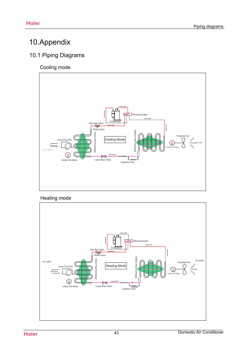
Piping diagrams
10.Appendix
10.1 Piping Diagrams
Cooling mode
Heating mode
43 Domestic Air Conditioner
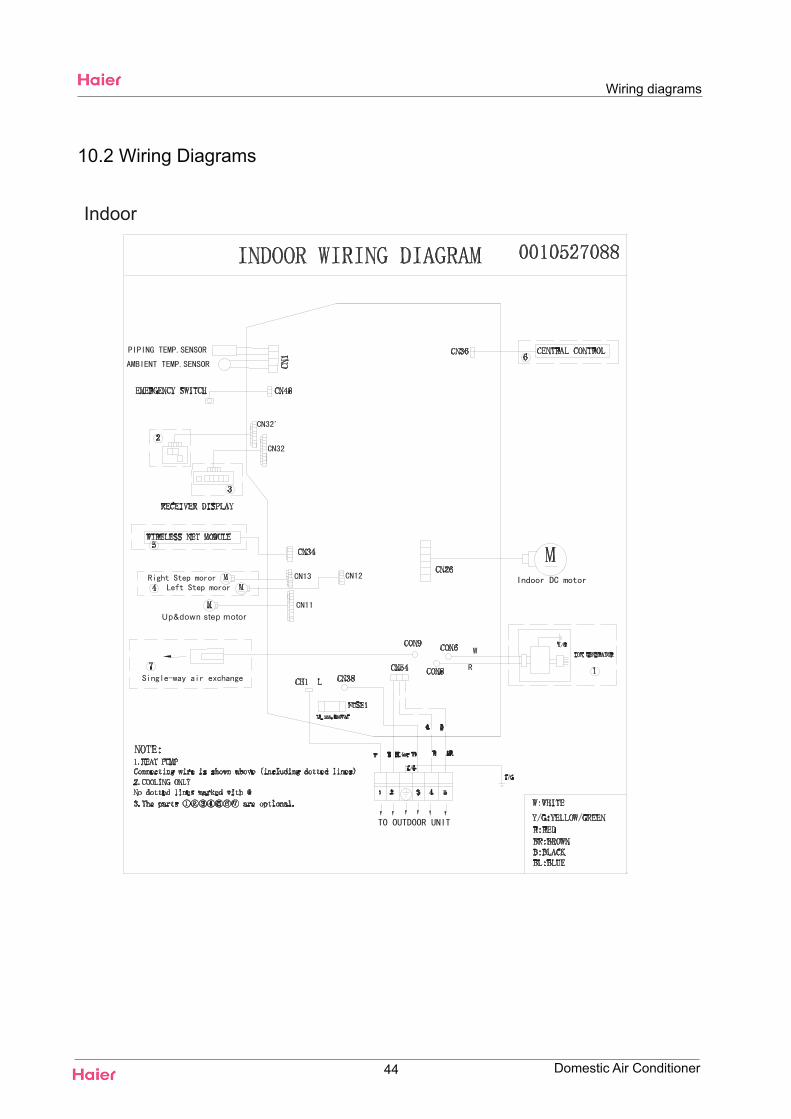
Indoor
10.2 Wiring Diagrams
Wiring diagrams
Domestic Air Conditioner
Up&down step motor
44
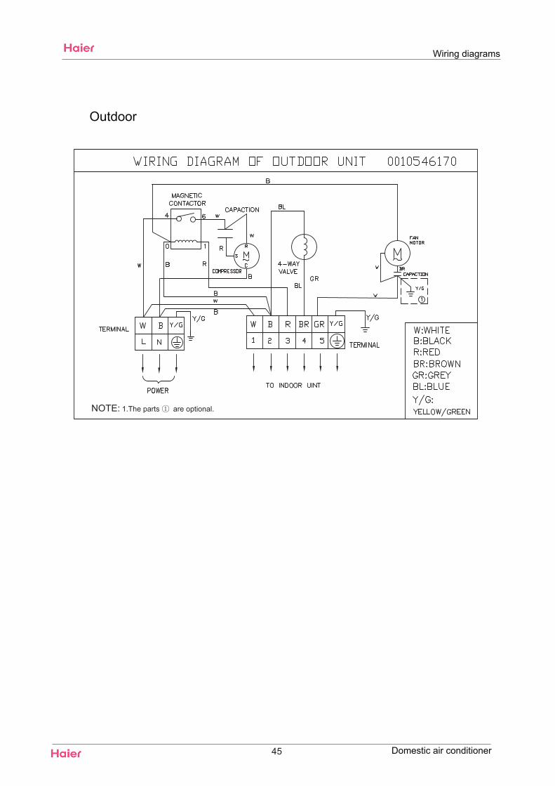
45
Wiring diagrams
Domestic air conditioner
Outdoor
1.The parts are optional.NOTE:
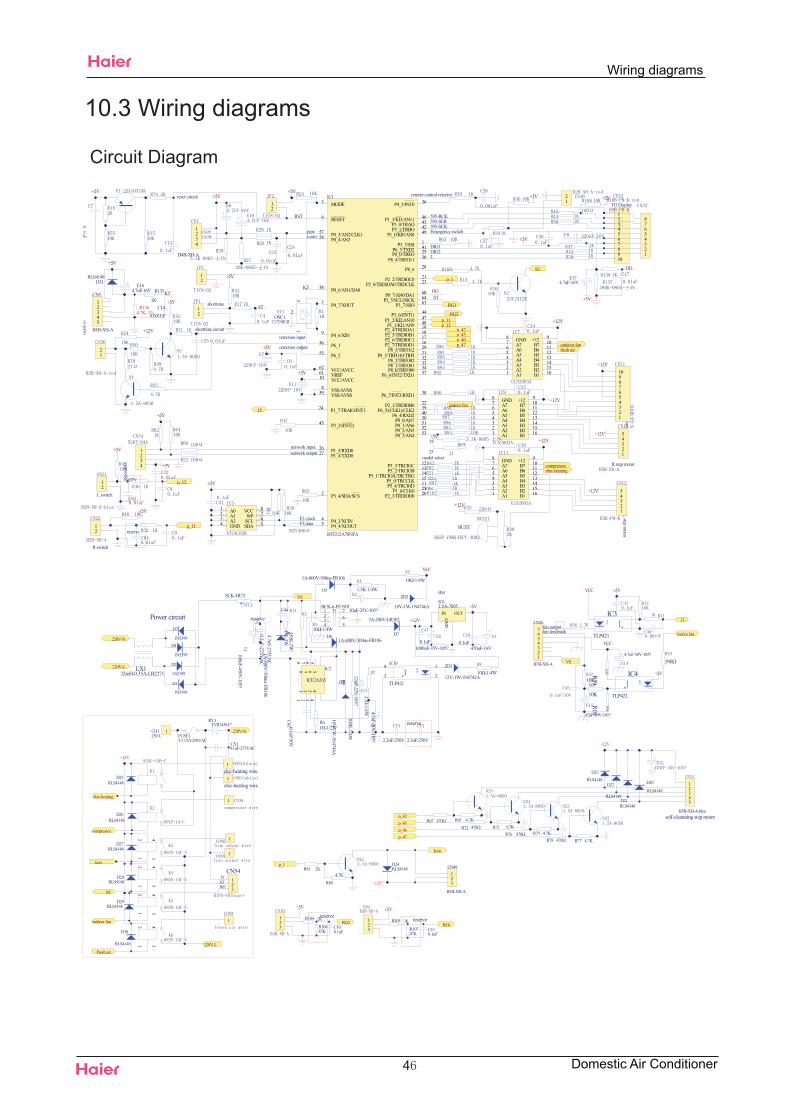
10.3 Wiring diagrams
Circuit Diagram
4
Wiring diagrams
Domestic Air Conditioner
RST
roompipe
OSC1
remotion input
remotion output
network outputnetwork input
E2 dataE2 clock
remote control reiceive
595-SCK595-SER595-RCK
+5Vreset circuit +5V
1234
12
+5V
shorttime circuit
shorttime
13
2
12
+12V
+5V
A01A12A23GND4 SDA 5SCL 6WP 7VCC 8
+5V
+12V
1234
+5V
network
+5V
+5V
12345678910
+5V
Emergency switch+5V
DIG1DIG2L
fresh air
indoor fan
outdoor fan
elec-heatingcompressor
ST
A11 A22 A33 A44 A55 A66 A77 GND8 +12 9B7 10B6 11B5 12B4 13B3 14B2 15B1 16
+12V
A11 A22 A33 A44 A55 A66 A77 GND8 +12 9B7 10B6 11B5 12B4 13B3 14B2 15B1 16
+12V
A11 A22 A33 A44 A55 A66 A77 GND8 +12 9B7 10B6 11B5 12B4 13B3 14B2 15B1 16
+12V+5V35
25model select
+12V
+12V
Up&down
stepmotor
Lstep
motor
R stepmotor
BUZZ
B4B-XH-A
+5V
TODisplay
p_42p_43p_46p_47
12
+5V
Rswitch
12
Lswitch
+5V p_1
p_12
p_11
p_12p_11
10987654321
12345
12345
+5V
12
12
12
+12V
12345678
E174.7uF-16V
+5V
GG
R1364.7K- 1%
C140.001UF
R135
1K
E164.7uF/16V
D31RLS4148
airquali ty
KZ
12345
CN5
B5B-XH-A
+5V
ST
GGKZ
RG1
RG2
ST
P3_3/SSI 1
P3_4/SDA/SCS2
MODE3
P4_3/XCIN4P4_4/XCOUT5
RESET6
P4_7/XOUT7
VSS/AVSS8
P4_6/XIN9
VCC/AVCC10
P5_4/TRCIOD 11
P5_3/TRCIOC 12P5_2/TRCIOB 13
P5_1/TRCIOA/TRCTRG 14P5_0/TRCCLK 15
P2_7/TRDIOD1 16P2_6/TRDIOC1 17P2_5/TRDIOB1 18P2_4/TRDIOA1 19
P2_3/TRDIOD0 20
P2_2/TRDIOC0 21
P2_1/TRDIOB0 22
P2_0/TRDIOA0/TRDCLK 23
P1_7/TRAIO/INT124
P1_6/CLK0 25
P1_5/RXD026P1_4/TXD027
P8_6 28
P8_5/TRFO12 29
P8_4/TRFO11 30
P8_3/TRFO10/TRFI 31P8_2/TRFO02 32P8_1/TRFO01 33P8_0/TRFO00 34
P6_0/TREO 35
P4_5/INT0 36
P6_6/INT2/TXD1 37
P6_7/INT3/RXD1 38
P6_5/(CLK1)/CLK2 39P6_4/RXD2 40
P6_3/TXD2 41
P3_1/TRBO 42P3_0/TRAO 43
P3_6/(INT1) 44
P3_2/(INT2)45
P1_3/KI3/AN11 46
P1_2/KI2/AN10 47P1_1/KI1/AN9 48
P1_0/KI0/AN8 49
P0_0/AN7 50P0_1/AN6 51P0_2/AN5 52P0_3/AN4 53
P0_4/AN354
P6_255P6_156
P0_5/AN2/CLK157
P0_6/AN1/DA058
VSS/AVSS59
P0_7/AN0/DA1 60
VREF61 VCC/AVCC62
P3_7/SSO 63P3_5/SCL/SSCK 64
IC1
R5F212A7SNFA
15
reserve
reserve
+5V
LX132mH-0.35A-LB2271
Power circuit
D4
1N5399
D3
1N5399
D2
1N5399
D1
1N5399
220V-N
220V-L
+12V
43
21
43
21
1
1
220V-L
elec-heating
compressor
ST
outdoor fan
43
21
Fresh air
1
elec-heatingwire
123
CN54
WFSTN
220V-N
CX10.1uF-275VAC
RV1TVR14561*
FUSE1T3.15A/250VAC
1CH1250L
43
21
1
icon
+12V
123
CN49
B3B-XH-A
Icon
R81 2K
R80
4.7K
D24RLS4148
p_1
12345
+12V
self-cleanning stepmotorB5B-XH-A-blue
R78 470Ω R77 4.7K
D23RLS4148
D22
RLS4148D21RLS4148
D20
RLS4148
R76 470Ω R75 4.7KR72 470Ω R71 4.7K
R67 470Ω R61 4.7Kp_42p_43p_46p_47
D25RLS4148
D26RLS4148
D27RLS4148
D28RLS4148
D29RLS4148
D30
RLS4148
1
1elec-heatingwire
+12V
+5V
1000uF-35V-105?
22uF-25V-105?
10Ω-1/4W
SCK-4R721.5K-1/4W
100uF-450V-105?
330K-2W
10Ω-1/4W
27Ω-1/4W
47K-2W
10Ω-1/4W
4.7uF-50V-105?
10uF-25V-105?
VCC
VS
0.1uF 0.1uF
C44
4.7nF-275VAC
162
354
7T1BCK-6-FE1901
C43 0.1uF /50V
11
22
33
44
55
66
77
88
IC2
ICE2A265
ZD2
18V-1W-1N4746A
ZD3
12V-1W-1N4742AZD1
18V-1W-1N4746A
D6
1A-800V-500ns-FR106
D5
1A-800V-500ns-FR106
D81A-800V-500ns-FR106
D7
3A-200V-ER302IN
GND
OUT
IC61.5A-7805
470uF-16V
1
2
4
3
IC10
TLP421
R61Ω-1/2W
R9100K-1/4W
HS1
2.2nF/250V 2.2nF/250V
reserve
0.1uF-275VAC
reserve
+5V
fan feedback
VCC
390ΩVS
R10R59
10K
IC3
TLP421
IC4
TLP421
VCC
47uF-50V-105?
10K
fan output
+5V
1234567
CN26
B7B-XH-A
4.7uF-50V-105?
15
indoor fan
R104 2K
C100.1uF
+5V
123
R105 2K
C110.1uF
+5V
123
RG1RG2R10647K R107
47K
reservereserve
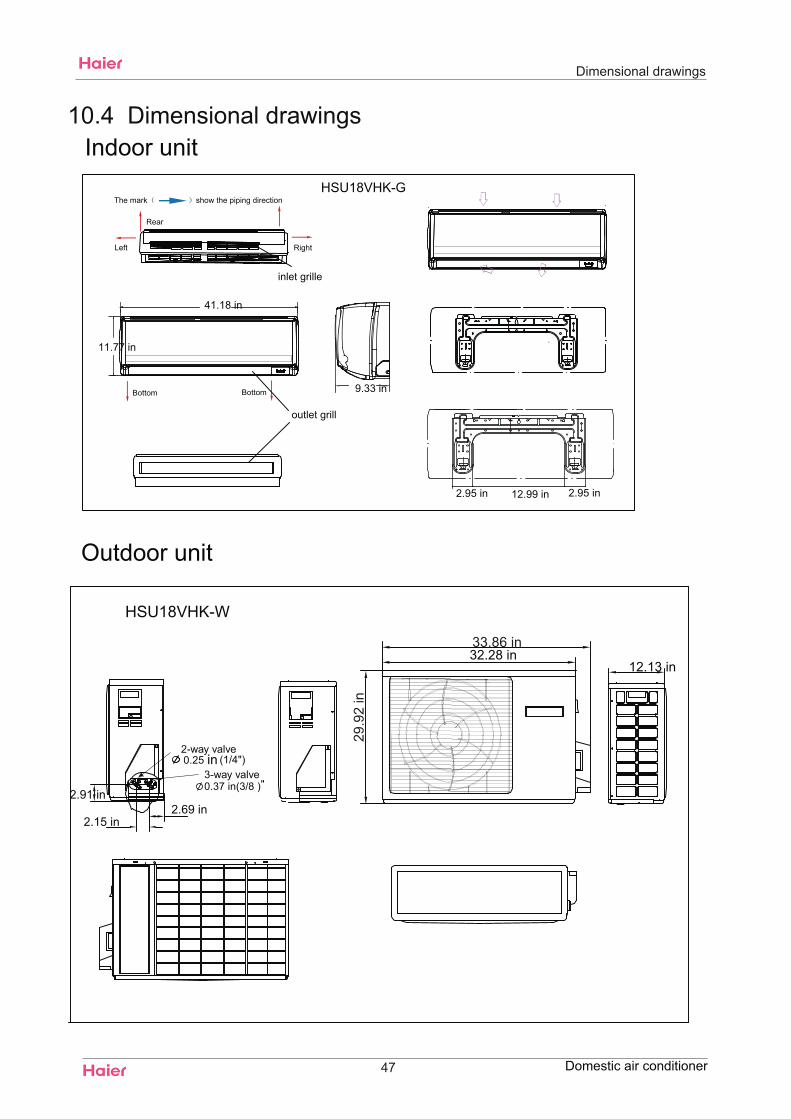
Dimensional drawings
10.4 Dimensional drawings
HSU18VHK-G
47
Indoor unit
Domestic air conditioner
2.95 in 12.99 in 2.95 in
11.77 in
41.18 in
9.33 in
HSU18VHK-W
in0.25
2.91 in
2.15 in2.69 in
33.86 in
29.9
2 in
0.37 in(3/8 )
32.28 in12.13 in
Outdoor unit
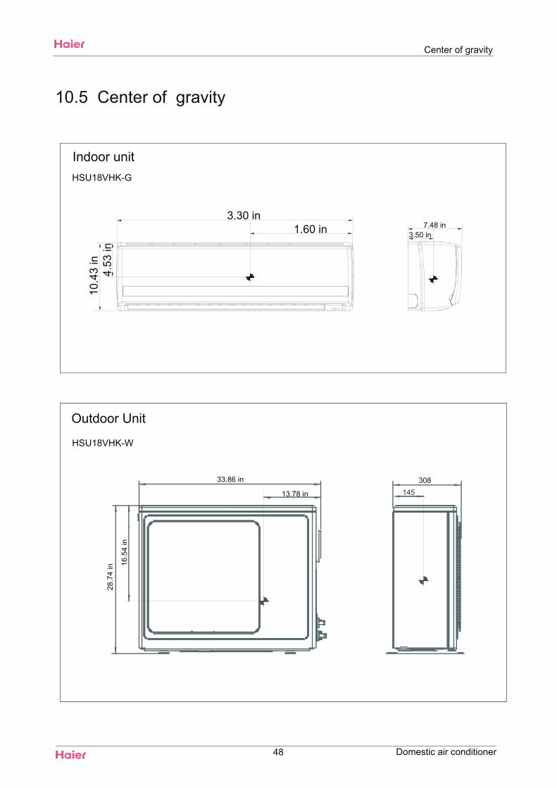
Indoor unit
10.5 Center of gravity
3.30 in
10.4
3 in
7.48 in1.60 in
4.53
in
3.50 in
Center of gravity
HSU18VHK-G
Domestic air conditioner
13.78 in
33.86 in
Outdoor Unit
HSU18VHK-W
16.5
4 in
28.7
4 in
48
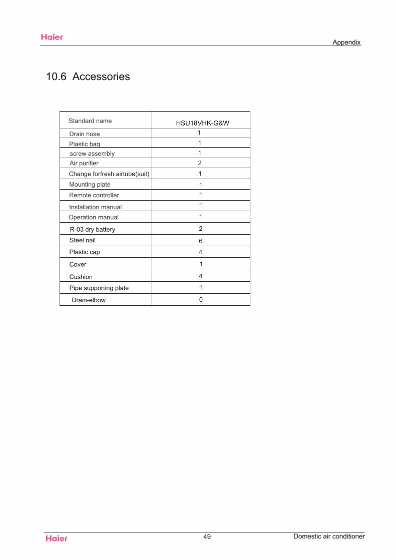
10.6 Accessories
R-03 dry battery 2
6
Plastic cap 4
Cover 1
4
Pipe supporting plate 1
Drain-elbow 0
Steel nail
Cushion
49
Appendix
Domestic air conditioner
HSU18VHK-G&W
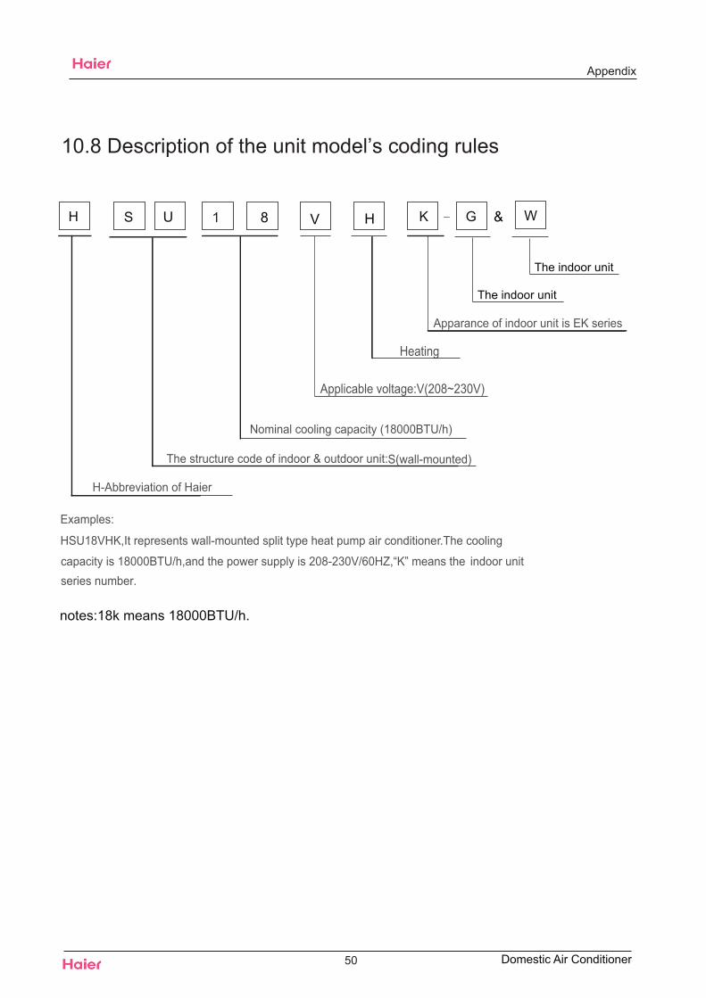
Appendix
10.8 Description of the unit model’s coding rules
Examples:
HSU18VHK,It represents wall-mounted split type heat pump air conditione r.The cooling
capacity is 18000BTU/h,and the power supply is 208-230V/60HZ,“K” means the indoor unitseries number.
Applicable voltage:V(208~230V)
Heating
Apparance of indoor unit is EK series
Nominal cooling capacity (18000BTU/h)
The structure code of indoor & outdoor unit: S(wall-mounted)
H-Abbreviation of Haier
H S U
notes:18k means 18000BTU/h.
1 K
50
8 H
Domestic Air Conditioner
V G & W
The indoor unit
The indoor unit
The end
Sincere Forever
Haier Group
26601,Qingdao,ChinaE-mail:[email protected]
Tel:+86 0532 8893 6935
Http://www.haier.com
Haier Industrial Park,NO.1,Haier Road Edited by:Wang Yujie Wang YueliangSigned by:He ShiquanApproved by:Wu Hongjin
Domestic air conditioner