Embed Size (px)
Citation preview

More time on the road®
Spicer TPCS (Tire Pressure Control System)
Service ManualAXSM0010
January 2007
®

2
General Information
The description and specifications contained in thisservice publication are current at the time of printing.
Eaton Corporation reserves the right to discontinue ormodify its models and/or procedures and to changespecifications at any time without notice.
Any reference to brand name in this publication ismade as an example of the types of tools and materialsrecommended for use and should not be considered anendorsement. Equivalents may be used.
This symbol is used throughout thismanual to call attention to procedureswhere carelessness or failure to followspecific instructions may result inpersonal injury and/or componentdamage.
Departure from the instructions,choice of tools, materials and recom-mended parts mentioned in thispublication may jeopardize the per-sonal safety of the service technicianor vehicle operator.
WARNINGS: Failure to follow indi-cated procedures creates a high riskof personal injury to the servicingtechnician.
CAUTION: Failure to follow indicatedprocedures may cause componentdamage or malfunction.
NOTE: Additional service information notcovered in the service procedures.
Tip: Helpful removal and installationprocedures to aid in the service of this unit.
!
!!
Always use genuine Eaton replacement parts.
IMPORTANT NOTICE
Every effort has been made to ensure the accuracy of all information in this guide. However, Eaton Axle andBrake Division makes no expressed or implied warranty or representation basedon the enclosed information.
Any errors or omissions may be reported to:Technical Publications, Eaton Corporation, P.O. Box 4013, Kalamazoo, MI. 49003

3
Section 1: IntroductionTire Pressure Control System ............................................................................................................................. 7Purpose and Scope of Manual ............................................................................................................................ 7Organization of Manual ....................................................................................................................................... 7
Section 2: OperationComponent Description ...................................................................................................................................... 8System Operation ............................................................................................................................................. 10Air Seal Life ...................................................................................................................................................... 10
Section 3: Electrical ServiceTerminal, Connector and Wire Service .............................................................................................................. 13Splicing Wire .................................................................................................................................................... 14Speed Sensor Repair/Replacement................................................................................................................... 15Wiring Connections .......................................................................................................................................... 16Configuration Connector ................................................................................................................................... 16Relay and Power Connections .......................................................................................................................... 16Vehicle Grounds ............................................................................................................................................... 16Lamp Switch ..................................................................................................................................................... 16Electronic Control Unit Replacement ................................................................................................................ 17Operator Control Panel Replacement ................................................................................................................ 17Operator Control Panel Back Lamp Removal .................................................................................................... 17Pressure Transducer ......................................................................................................................................... 17
Section 4: Pneumatic ServiceService Guidelines ............................................................................................................................................ 18Pneumatic Control Unit Replacement ............................................................................................................... 21Pressure Switch ............................................................................................................................................... 22Steer Axle Pneumatic Replacement .................................................................................................................. 24Drive Axle Pneumatic Replacement .................................................................................................................. 26Trailer Axle Pneumatic Replacement ................................................................................................................. 28Wheel Valve Air Filter Change ........................................................................................................................... 31
Section 5: Non-Drive Axle Wheel End ServicePreparation ....................................................................................................................................................... 32Wheel End Air Line Removal............................................................................................................................. 32Wheel Removal ................................................................................................................................................. 32Hubcap Removal .............................................................................................................................................. 34Hub Service ...................................................................................................................................................... 34Inlet Tube Removal (Steer Axles Only) .............................................................................................................. 34Inlet Tube Installation ....................................................................................................................................... 35Spindle Adapter Removal (Trailer Axles Only) .................................................................................................. 35Internal Air Line Installation (Trailer Axles Only) ............................................................................................... 36Rotary Joint, Nested Hubcap Installation .......................................................................................................... 37Wheel and Wheel Valve .................................................................................................................................... 37Wheel Changing Procedure .............................................................................................................................. 39Wheel Installation ............................................................................................................................................. 39
General Information

4
Section 6: Drive Axle Wheel End ServicePreparation ....................................................................................................................................................... 40Wheel and Wheel Valve Removal ...................................................................................................................... 40Hub, Oil Seal And Air Seal Removal .................................................................................................................. 40Wheel End Disassembly ................................................................................................................................... 40Sleeve Removal ................................................................................................................................................ 41Sleeve Installation ............................................................................................................................................. 42Install Drive Axle Inlet Tube .............................................................................................................................. 44Retightening Sequence ..................................................................................................................................... 44Air Seal Installation ........................................................................................................................................... 44Oil Seal Installation ........................................................................................................................................... 45Wheel Hub Installation ...................................................................................................................................... 45Wheel and Wheel Valve .................................................................................................................................... 48
Section 7: System Setup and CheckoutIntroduction ...................................................................................................................................................... 50System Setup ................................................................................................................................................... 50
Section 8: Operator ControlsIntroduction ...................................................................................................................................................... 51Fault Codes ....................................................................................................................................................... 52Tire Pressure Control System Programming .................................................................................................... 55Programming Quick Reference Chart ............................................................................................................... 57
General Information

5
List of IllustrationsFigure 1 Tire Pressure Control System Component Identification ...................................................................... 9Figure 2 Tire Pressure Control System Simplified Schematic ........................................................................... 11Figure 3 Wiring Harness Diagram ..................................................................................................................... 12Figure 4 Replacing Terminals ............................................................................................................................ 13Figure 5 Splicing Wire ...................................................................................................................................... 14Figure 6 Speed Sensors .................................................................................................................................... 15Figure 7 Terminal Connections ......................................................................................................................... 16Figure 8 Overview of Tractor Air Line Routing .................................................................................................. 19Figure 9 Hose/Configuration Requirements ...................................................................................................... 20Figure 10 Pneumatic Control Unit and Pneumatic Layout................................................................................. 21Figure 11 Routing for Wet Tank Pneumatics ..................................................................................................... 23Figure 12 Steer Axle Air Line Routing ............................................................................................................... 25Figure 13 Branch Tee Axle Mounting ................................................................................................................ 26Figure 14 Drive Axle Air Line Routing ............................................................................................................... 27Figure 15 Overview of Trailer Air Line Routing.................................................................................................. 28Figure 16 Trailer Axle Pneumatics ..................................................................................................................... 30Figure 17 Air Filter Change ............................................................................................................................... 31Figure 18 Run Tee ............................................................................................................................................. 32Figure 19 Non-Drive (Steer) Axle Wheel Air Line Routing – Rotary Joint Configuration ................................... 33Figure 20 Non-Drive Hubcap Installation – Rotary Joint Configuration ............................................................ 34Figure 20A Inlet Tube Installation (Steer) .......................................................................................................... 35Figure 21 Axle End Air Line Routing ................................................................................................................. 36Figure 22 Proper Hose Position ........................................................................................................................ 37Figure 23 Add Lube Position and Check ........................................................................................................... 37Figure 24 Run Tee ............................................................................................................................................. 38Figure 25 Drive Wheel Air Line Routing ............................................................................................................ 39Figure 26 Axle Shaft Removal ........................................................................................................................... 40Figure 27 Wheel Hub Removal ......................................................................................................................... 41Figure 28 Spindle Sleeve Depth Measurement.................................................................................................. 42Figure 29 Sleeve Inner O-Ring Installation........................................................................................................ 42Figure 30 Spindle Preparation .......................................................................................................................... 43Figure 31 Spindle O-Ring and Backup Ring ...................................................................................................... 43Figure 32 Preparation for Sleeve Installation .................................................................................................... 43Figure 33 Wheel Hub Preparation for Installation ............................................................................................. 44Figure 34 Wheel Hub Installation ...................................................................................................................... 45Figure 35 Adjusting Nut Identification............................................................................................................... 46Figure 36 Sleeve O-Ring Leak Test ................................................................................................................... 46Figure 37 Run Tee ............................................................................................................................................. 48Figure 38 Drive Axle Wheel Air Line Routing .................................................................................................... 49Figure 39 Operator Control Panel ..................................................................................................................... 51Figure 40 Entering the Programming Sequence ............................................................................................... 56Figure 41 Entering the Programming Sequence Chart ...................................................................................... 57Figure 42 Fastener Torques .............................................................................................................................. 58
General Information

6
General Information

7
Tire Pressure Control System
Eaton’s Tire Pressure Control System features dash-board control of tire air pressure through:
• Simple push button operation.
• Independent Steer, Drive, and Trailer operation.
• Electronic braking priority for air system.
• Vehicle speed sensing and response capability.
• Self-diagnostics.
Purpose and Scope of Manual
This manual explains how to make repairs to the EatonTire Pressure Control System. While this manual alsoincludes a basic summary of system components andcontrol operation, it does not provide all informationnecessary to fully support an installed Tire PressureControl System. For information on troubleshooting,installation and full system operation, request appropri-ate documents from your Eaton representative.
• Installation Guide
• Operator's Guide
• Illustrated Parts List
• Troubleshooting Guide
Organization of Manual
The following is an overview:
Section 1: Introduction. Describes the purpose,scope, and organization of this manual as well asintroduces the Tire Pressure Control System.
Section 2: Operation. Reviews the components thatmake up the Tire Pressure Control System as well asgives a simplified scenario of how the Tire PressureControl System functions.
Section 3: Electrical Service. Covers the Serviceprocedures for the electrical components of the TirePressure Control System.
Section 4: Pneumatic Service. Covers the Serviceprocedures for the pneumatic components of the TirePressure Control System.
Sections 5: Non-Drive Axle Wheel End Service.Covers the Service procedures for the Steer and TrailerAxle wheel components of the Tire Pressure ControlSystem.
Section 6: Drive Axle Wheel End Service. Covers theService procedures for the drive axle wheel componentsof the Tire Pressure Control System.
Section 7: System Setup and Checkout. Covers howto check the system after servicing the Tire PressureControl System.
Section 8: Operator Controls. Describes how tooperate the system with the Operator Control PanelComponent Description.
IntroductionPurpose and Organization
of Manual

8
Component Description
The following describes how each component of theTire Pressure Control System functions. Figure 1shows the approximate location of each component.
Wheel Valve
All axles under tire pressure control incorporate a wheelvalve at each wheel end. Dual wheels are typicallyconnected to one wheel valve at the outer wheel toprovide tire pressure balance. When the system is idle,the wheel valve isolates the tire(s) from the system,thereby extending seal life since the seals are not underconstant pressure. The valve also ensures fail safeoperation should the system become disabled orinoperable. The wheel valve provides for inflation of thetires from the vehicle air supply via the pneumaticcontroller, and deflation of the tires upon systemdemand.
Electronic Control Unit (ECU)
The Electronic Control Unit is the control center for theentire Tire Pressure Control System. The ElectronicControl Unit receives commands from the driverthrough the Operator Control Panel and transmitsappropriate signals throughout the system. TheElectronic Control Unit is typically mounted in the cabbehind the passenger seat near the Pneumatic ControlUnit.
Operator Control Panel (OCP)
By using the Operator Control Panel keys, the operatorselects tire pressures for the conditions encountered.The panel also displays such system parameters ascurrent tire pressures, selected modes, and systemstatus. The Operator Control Panel is typically mountedon the dash within view and reach of the driver.
Pneumatic Control Unit (PCU)
The Pneumatic Control Unit is a solenoid controlledmanifold that receives commands from the ElectronicControl Unit and controls the air system. It alsocontains the pressure transducer which transmits thepressure readings to the Electronic Control Unit. ThePneumatic Control Unit delivers the proper controlsignal to the appropriate channel (steer/drive/trailer).
Speed Sensor
The speed sensor provides the Electronic Control Unitwith vehicle speed information. If the vehicle speed isabove programmed limits, the system will display anoverspeed indication on the Operator Control Panel.Continued operation in this condition will cause thesystem to automatically inflate the tires to a moreappropriate pressure.
Pressure Switch
The pressure switch acts as an electronic brake priorityswitch. It prevents the Tire Pressure Control Systemfrom consuming air from the wet tank until the brakesystem is fully charged. This prevents the Tire Pres-sure Control System from allowing the primary andsecondary tanks to go below recommended operatingpressures for braking.
Operation

9
Air Lines
The Tire Pressure Control System uses a dedicatedpneumatic system plumbed from the vehicle’s existingwet tank.
Wiring
All electric cables and connectors are supplied in anintegrated harness.
OperationCom
ponent Description
Figure 1 Tire Pressure Control System Component Identification

10
System Operation
A vehicle equipped with the Tire Pressure ControlSystem will seem to operate the same as a vehiclewithout the Tire Pressure Control System, however,there are some differences:
• During normal operation, the ElectronicControl Unit will check tire pressures every 15minutes to make sure that pressures aremaintained at selected settings.
• Immediately after a pressure change, thepressure is rechecked after approximately30 seconds.
• During the run flat mode, tire pressures arechecked at an increased rate.
During all of the above checks, solenoid clicking and airexhausting from the Pressure Control Unit may beheard.
The following is a description of how the Tire PressureControl System functions. Figure 2 shows a simplifiedschematic of how the components of the system relateto one another.
Pressure Regulation
The Tire Pressure Control System regulates tire pres-sures through a series of electro-pneumatic controlsthat supply air to each wheel end through wheel valves.The driver operates a dash-mounted, graphic-controlpanel (the Operator Control Panel) which commandsthe system to adjust tire pressure.
Pressure Mode
The driver selects a desired tire pressure mode bypressing buttons on the Operator Control Panel. Thesystem responds by adjusting tire pressures to matchthe road surface and load. Indicators on the OperatorControl Panel inform the driver of functions currentlybeing performed.
Operator Control Panel
The Operator Control Panel also contains a built-inindicator to warn drivers when they are travelling toofast for selected tire pressures. If the vehicle’s speed isnot reduced, the Tire Pressure Control System willautomatically select the appropriate pressure. Addition-ally, a warning icon will inform the driver to stop andcheck the tires if the system senses conditions that mayindicate tire damage.
Air Seal Life
When the Tire Pressure Control System is idle, notinflating, deflating or checking pressure, all tire airpressures are isolated from the Tire Pressure ControlSystem. Tire pressure isolation extends seal lifebecause the seals are not under continuous pressure.Isolation also provides fail-safe operation of the vehicleif the Tire Pressure Control System is disabled.
Operation

11
Figure 2 Tire Pressure Control System Simplified Schematic
OperationSystem
OperationAir Seal Life
Wheel Valve
To Trailer
Wheel Valve
Wheel Valve
Speed Sensor
Compressor
Wheel Valve
Wheel Valve
Pneumatic
Electrical
SYSTEM KEY
Pressure Control
Unit
Pressure Transducer
Wheel Valve
Electronic Control
Unit
Operator Control Panel
To Primary and Secondary
Tanks
TireTire
TireTire
TireTire
Wet Tank
Pressure Switch
Air Dryer

12
Figure 3 Wiring Harness Diagram
Note: The wiring harness connects all electricalcomponents of the Tire Pressure Control System.Figure 3 is a diagram of a wiring harness that showsthe various connectors and their attachment points.Refer to this figure when performing any of thefollowing procedures.
Note: See Tire Pressure Control System Trouble-shooting Guide for a wiring schematic of the TirePressure Control System.
Note: See the Troubleshooting Manual for procedureson running diagnostics on the Tire Pressure ControlSystem.
Note: See Section 4: Pneumatic Service for instruc-tions on replacing the Pneumatic Control Unit, replacingthe Pneumatic Control Unit’s Pressure Transducer, andreplace the Pressure Switch.
Electrical Service
1 2 4 5 6
Electronic Control Unit
Speed Sensor
Pressure Switch
Vehicle Power
Relay
Operator Control PanelPneumatic
Control UnitPressure Transducer
Diagnostic
Config
GND
GND
See Figure 7
Ground Terminal
A B C D E F J K
C E G H J
C E F G
321
C D
B C D E
F
A B
A B
A B C
CEA
B
A B C
A B C D E
K H G F

13
Terminal, Connector and Wire Service
The Tire Pressure Control System electrical systemrequires good electrical signal paths. Proper installa-tion and maintenance of wires and connectors areessential to the proper operation of the Tire PressureControl System. The following procedures are recom-mended for replacing terminals and connectors andmaking wire splices.
Figure 4 shows the steps to put a new terminal on awire. Note the two sets of wings: one set crimps thecore and one set crimps the insulation.
To replace a terminal:
1. Make sure the insulation is removed cleanly andthat the wire strands are undamaged.
2. Install new weather boot on wire, placed in properdirection.
3. For a “pull-to-seat” terminal, feed plain wirethrough connector before attaching terminal.
4. Position wire in terminal. First crimp core wings,then crimp insulation wings.
5. After making a hand crimp, solder the terminal.
Solder all Hand-Crimped Terminals
Minimize Wire Loss
Cutting Off Defective Terminals
Figure 4 Replacing Terminals
1. Crimp Core Wire 2. Crimp Insulation
Insulation WingsCore Wings
Positioning Strip in Terminal
Electrical ServiceTerm
inal, Connectorand W
ire Service
Take Care Not To Cut Wire Strands
Removing Insulation

14
Splicing Wire
Figure 5 shows the steps to splice two sections of wire.
Remove insulation cleanly taking care not to damagewire strands. Slide automotive grade heat shrink overarea to be sealed and slide to one side. After hand
Figure 5 Splicing Wire
Solder All Hand Splices
Take Care Not To Cut Wire Strands
Removing Insulation
Cover Entire Splice with Automotive Grade
Heat Shrink Tubing
2" of Automotive Grade Heat Shrink (with adheasive lining)
Tubing Extends onto Insulation on Both Sides of Splice
Electrical Service
Position Both Wire Ends
in Splice Clip
Slide Automotive Grade Heat Shrink
to one side.
Tightly Crimp Spliced Wires
crimping splice clip, the joint should be soldered.Cover entire splice with automotive grade heat shrink,making sure heat shrink extends over insulation onboth sides of splice.

15
Speed Sensor Repair/Replacement
The first step in replacing the speed sensor is todetermine the type. Figure 6 illustrates two types ofsensors. After determining the type, follow the corre-sponding replacement procedures.
Magnetic Sensor
Note: This procedure requires cutting the existingvehicle speedometer wires and splicing these wires withthe second set of wires from the Speed Sensor.
This procedure only applies to the dual coil (bifilar)sensor. Single coil sensors are a direct replacement.
1. Turn off the vehicle’s ignition and engine.
2. Locate the Speed Sensor. The Speed Sensor islocated on the output shaft bearing cover of thetransmission or transfer case.
3. Disconnect the connector on Tire Pressure ControlSystem harness.
4. Cut off vehicle speedometer sensor connector atbutt splice leaving 3" of wire on connector side.
5. Strip 3/16" of insulation off the vehicle speedometerconnector wires.
6. Remove the locking nut for the old speed sensorand unscrew it.
7. Thread the new Dual Output Electrical SpeedSensor in by hand until it bottoms out and thenback it out 1/2 turn. Secure with locking nut.
8. Slide heat-shrink tubing provided (2" long) overeach of the new Speed Sensor wires.
9. Install and crimp butt splices connecting vehiclespeedometer wires and new Speed Sensor wires.
10. Center the Heat-Shrink tubing over the butt spliceand apply suitable, low level heat.
11. After heat application, check for adhesive flow ofeach end of tubing.
12. Connect the Tire Pressure Control System wiringconnector to the new Speed Sensor.
13. Check all wiring for appropriate clearance.
14. Start the vehicle and test the Tire Pressure ControlSystem.
Mechanical Sensor
1. Turn off the vehicle’s ignition and engine.
2. Locate the Speed Sensor. The Speed Sensor islocated on the output shaft bearing cover of thetransmission or transfer case.
3. Disconnect the Tire Pressure Control Systemwiring connector from the old Speed Sensor.
4. Unscrew the speedometer cable from the oldSpeed Sensor.
5. Remove Speed Sensor.
6. Align drive tangs and thread in new speed sensor.Torque to 12–15 lbs. ft. (16–20 N•m).
7. Connect the Tire Pressure Control System wiringconnector to the new Speed Sensor.
8. Thread the speedometer cable onto new SpeedSensor.
9. Check all wire routing for appropriate clearance.
10. Start the vehicle and test the Tire Pressure ControlSystem.
Magnetic
Figure 6 Speed Sensors
Mechanical
Electrical ServiceSplicing W
ireSensor Repair/Replacem
ent

16
Wiring Connections
Configuration Connector
This connector initializes the Electronic Control Unit forthe current vehicle configuration (see Figure 9). De-pending on application, factory supplied jumper con-nector may be provided.
Relay and Power Connections
Figure 7 shows the terminal connections to the relayand the vehicle power panel. The connections must bemade as shown. The relay lugs plug into the bottom ofthe relay sockets.
Vehicle Grounds
There are three ground terminals that must be securedto the vehicle chassis. The ground terminals are for theElectronic Control Unit, Operator Control Panel andvehicle interface. Figure 3 shows the three grounds andtheir attachment points.
Caution: The battery and the switched ignition arefused individually with a circuit breaker or a fuse.(See Figure 7 for power requirements.)
Lamp Switch
The lamp wire provides back-lighting for the OperatorControl Panel keypad and dims the display. Somevehicles use a separate switch to control intensity. Thismay be connected to the headlamp circuit, a day timerunning light (DRL) system or a separate switch. Thisis a switched input and cannot be connected directly tothe dimmer switch.
Electrical Service
!
Figure 7 Terminal Connections
RSP 3
VBATT 2
VBATT 1
RLY1ENA
Relay Lugs
Vehicle Power Panel
VBATT
SWACC 3
1 4 2
5
3
Relay Top View (relay side)
To battery 20 amp fuseTo ignition switch 5 amp fuse
GND 8 (vehicle ground)
LAMP 2
Lamp SwitchNormal (Bright)
Dim
To headlamp
or
No Connection

17
Electrical ServiceReplacem
ent Procedures
Electronic Control Unit Replacement
1. Turn off the vehicle’s ignition and engine.
2. Locate the Electronic Control Unit. The ElectronicControl Unit is typically mounted in the cab behindthe passenger seat.
3. Use a hex driver to disconnect the two wire harnessconnectors.
4. Remove the Electronic Control Unit.
5. Mount the new Electronic Control Unit.
6. Connect the wire harness.
7. Start the vehicle and test the Tire Pressure ControlSystem.
Operator Control Panel Replacement
1. Turn off the vehicle’s ignition and engine.
2. Locate the Operator Control Panel. The OperatorControl Panel is typically mounted in the cab on thedash where the driver can easily access it.
3. Remove the four mounting screws and carefully pullthe Operator Control Panel through the dash.
4. Disconnect the wire harness connector from theOperator Control Panel.
5. Connect the wire harness to new Operator ControlPanel.
6. Mount the new Operator Control Panel with theexisting mounting hardware.
7. Start the vehicle and test the Tire Pressure ControlSystem.
Operator Control Panel Back Lamp Removal
1. Turn off the vehicle’s ignition and engine.
2. Locate the Operator Control Panel. The OperatorControl Panel is typically mounted in the cab on thedash where the driver can easily access it.
3. Remove the four mounting screws and carefully pullthe Operator Control Panel through the dash.
4. Disconnect the wire harness connector from theOperator Control Panel.
5. Remove back cover by pressing in the two tabsopposite the connector end.
6. With back cover off, place the Operator ControlPanel face down with the connector to the right.
Note: Lamp is located in the top left hand corner.
7. To remove lamp, insert small screwdriver in backof lamp and turn counterclockwise 1/4 turn toremove.
To install Operator Control Panel bulb, (partnumber 5559106) reverse removal procedures.
Pressure Transducer
1. Turn off the vehicle’s ignition and engine.
2. Disconnect electrical connectors at PneumaticControl Unit cover.
3. Remove the Pneumatic Control Unit Cover andlocate the pressure transducer.
4. Disconnect the wire harness connector from thepressure transducer.
5. Unscrew the pressure transducer and remove.
6. Screw new pressure transducer into the PneumaticControl Unit and tighten to 10–12 lbs. ft.(14–16 N•m).
7. Connect the internal wire harness connector to thepressure transducer and install protective cover.Torque cover fasteners to 35-45 lbs. in. (4-6 N•m).
8. Reconnect the Pneumatic Control Unit harnessconnector to the proper cover positions.
9. Start the vehicle and test the Tire Pressure ControlSystem.
Note: When repairs to the Pneumatic Controller havebeen completed, the servicing technician should assureproper system function before putting vehicle back inservice. As a minimum, the system should be inflatedusing the Operator Control Panel to achieve the high-way loaded setting and then deflated until the off-highway loaded setting is achieved.

18
Pneumatic Service
Wet Tank Requirements
A minimum wet tank volume is required for properoperation of the Tire Pressure Control System. Verifythat the vehicle is equipped with the proper Wet Tank:
• 1400 in3 (6 gal.) for tractor only or tractor/trailer configuration
• 2800 in3 (12 gal.) for a tractor with a twotrailer configuration. See Figure 9 for properhose selection. Do not reduce the size of wettank or hoses.
Supplied Parts and Fittings
In selecting parts, be alert to slight differences betweenitems and make sure you are using the correct part. Inparticular, watch out for different hose and tubinglengths and fitting diameters.
No Kinking or Stretching
All hose and tubing segments should assemble withslight excess lengths. There should be no kinks orsharp bends and no segments should require stretchingin order to tighten joints. When servicing hoses be surenot to increase or reduce overall control volumes. Ifany tube or hose segment does not fit easily, it couldmean you are not using the proper part or that you arenot following service procedures properly.
Joint Compound
Here are some important “DO’s” and “DON’Ts” regard-ing the use of thread sealant:
• Do apply a thin coating of compound on malethreads of pipe joints.
• Don’t use any compound on O-ring, compres-sion, or flare fitting connections. Instead, applya thin coat of silicone grease to O-rings andflares.
• Don’t use Teflon thread tape anywhere in the airsystem. (Teflon tape shreds can become lodgedin valving.)
! Caution: The Eaton Tire Pressure Control Systemhas the ability to maximize the vehicle’s ability tooperate in various conditions. Until the systemadjusts to repairs, tire pressures may be tempo-rally lower than expected. The above procedure isnecessary before returning the vehicle to service.
Note: Figure 8 shows the pneumatic layout for a three-axle installation of the Tire Pressure Control System.This layout is typical for a tractor or straight truck andshows the air line for a trailer connection. Refer to thisfigure when performing any of the following proce-dures.
Note: See the Troubleshooting Manual AXTS-0010 forprocedures on locating pneumatic problems with theTire Pressure Control System.
Note: See Section 3 on Electrical Service for informa-tion on electrical connections to the Pneumatic ControlUnit.
Service Guidelines
The Tire Pressure Control System does not requireadditional maintenance. However, additional care withthe vehicle’s air system may assure trouble free opera-tion. The following are some general rules that apply toTire Pressure Control System service:
Clean and Dry Air Supply
The Eaton Tire Pressure Control System requires aconstant supply of clean dry air. An adequately sized andproperly maintained air dryer is critical for continuedproper operation of the Tire Pressure Control System.Even though the air dryer may be working properly,moisture can accumulate in the wet tank during normaloperation due to the increase in air consumption. It isimportant to drain the wet tank daily. Draining the wettank completely (to 0 pressure) when the truck is not inuse will help keep moisture under control.

19
Figure 8 Overview of Tractor Air Line Routing
Pneumatic ServiceService Guidelines
Chassis Plumbing
Steer Wheel End Plumbing
Drive Wheel End Plumbing
Wet
TankAir
Dryer
PC
U
Tubing and Hoses
Plastic tubing is defined in this manual as nonmetallicair brake system tubing that meets or exceeds therequirements of SAE J844. Tubing that is approvedunder this SAE standard will be marked every 15" orless along the length of the tubing with the following:
• Air Brake
• SAE J844
• Type (A or B)
• Nominal tubing O.D. in fractions of an inch
• Tubing manufacturer’s identification
Wire braid hose is defined in this manual as automotiveair brake hose that meets or exceeds the requirementsof SAE J1402. Hose that is approved under this SAEstandard will be marked every 15" or less along thelength of the tubing with the following:
• Hose manufacturer’s identification
• Air brake
• Nominal hose I.D. in fractions of an inch
• SAE J1402

20
Figure 9 Hose/Configuration Requirements
Pneumatic Service
Note: Wire braid hose diameter is inside diameter (I.D.). Nylon hose diameter is outside diameter (O.D.).
*This length does not include the section from the frame to the inlet tube.
!
Air Line Support
Each segment of the pneumatic system must besecured to the vehicle frame or other installed line.After completing assembly of each segment, use cableties to anchor the segment at approximately 18" inter-vals.
Two Axle Truck (Config. 1)
Tire Pressure Control Hose/Configuration Requirements
1 2 3 4 51 2 3
1 2
Three Axle (Tandem) Truck, with or without Tandem Trailer (Config. 0)
Steer
17-19' of " OD*
Trailer
45-55' of " ID
30-40' of " OD
Drive
17-23' of " OD
Three Axle (Tandem) Truck, with or without Two Trailers (7 or 8 axles) (Config. 2)
Steer
17-19' of " OD*
Trailer
80-100' of " ID
55-70' of " OD
Drive
17-23' of " OD
1 2 3 4 5 6 7
or
Wet Tank Size
In3 (Gal)
Wet Tank Size
In3 (Gal)
Wet Tank Size
In3 (Gal)
1400 (6)
1400 (6)
2800 (12)
85/
21/ 85/
85/
85/
21/
21/21/
165/
165/
21/
Steer
17-19' of " OD*
Pneumatic Control Unit to trailer hose connection
5-30' of " OD
21/
Pneumatic Control Unit to trailer hose connection
5-30' of " OD
Trailer
N/A
Configuration Connector
Part Number
673443
Configuration Connector
Part Number
673444
Configuration Connector
Part Number
No Connector
Drive
14-16' of " OD
Hose Length
Hose Length
Hose Length
Hose Lengths
Caution: Proper Tire Pressure Control Systemoperation requires correct air line diameters andlengths for each channel.

21
!
Pneumatic ServicePneum
atic Control UnitReplacem
ent
4. Note the Pneumatic air line location, mark ifnecessary.
5. Remove the pneumatic connections from thePneumatic Control Unit.
6. Remove the Pneumatic Control Unit.
7. Mount the new Pneumatic Control Unit.
Note: Apply light coating of removable thread sealingcompound to the NPT fittings before installing.
8. Install 1/4" male NPT to 1/2" nylon air brake tubingfitting into Supply, Trailer, and Drive ports thePneumatic Control Unit.
9. Install 1/4" male NPT to 3/8" NPT female increasingadapter to 3/8" male NPT to 5/8" nylon air braketubing fitting into the steer port of the PneumaticControl Unit.
10. Attach the Pneumatic air line to the PneumaticControl Unit in the same locations as marked inStep 4.
Pneumatic Control Unit Replacement
Note: Refer to Figure 10 for the following steps.
1. Turn off the vehicle’s ignition and engine.
Warning: Drain off air from the wet tank beforeremoving any fittings!
2. Locate the Pneumatic Control Unit.
3. Disconnect the wire harness connectors from thePneumatic Control Unit.
Figure 10 Pneumatic Control Unit and Pneumatic Layout
Steer
Trailer (if equipped)
From Wet Tank
Drive
1
Top View
Pneumatic Control Unit
D O T
2
2
2
3
Vent Hose
1. Pneumatic Control Unit vent hose 5/8 ID vent (heater) hose
2. 1/4" male NPT to 1/2" nylon air brake tubing fitting
3. 1/4" male NPT to 3/8" NPT female increasing adapter to 3/8"male NPT to 5/8" nylon air brake tubing fitting
Note: Area highlighted shows typical connections. Actual fittings may vary by vehicle manufacturer.

22
Pneumatic Service
!
11. Install the Pneumatic Control Unit. Secure unitwith 1/4" x 20 mounting studs or bolts.
Note: For additional air line protection, rubber grom-mets are installed in the cab floor. Check condition ofthese grommets and replace if necessary.
12. Connect 5/8" I.D. vent hose to Pneumatic ControlUnit vent using hose clamp.
13. Connect the wire harness connections to thePneumatic Control Unit.
14. Start the vehicle and test the Tire Pressure ControlSystem.
Pressure Switch
Note: Refer to Figure 11 for the following steps.
Note: The following procedure discusses replacing thePressure Switch.
1. Turn off the vehicle’s ignition and engine.
2. Locate the Wet Tank. The Wet Tank is the firsttank from the dryer.
Warning: Drain off air from the Wet Tank beforeremoving any fittings!

23
Pneumatic Service
1. 3/8" NPT run Tee
2. 3/8"male NPT to 1/4" female NPTreducing adapter
3. Pressure switch
4. 1/2" NPT run Tee (varies with vehicle mfg.)
5. 1/2" male NPT to 1/2" nylon air brake tubing fitting
6. 1/2" nylon air brake tubing
From Air Dryer
Wet Tank
1
2
3 5
4
6
To Pneumatic Control
UnitRelief Valve
D O T
Note: Do not install pressure switch in supply line to the Pneumatic Control Unit.
Drain Cock
Figure 11 Routing for Wet Tank Pneumatics
Pressure Switch
Pressure Switch Replacement
1. Disconnect the electrical connector of the existingPressure Switch.
2. Unscrew the existing Pressure Switch.
3. Install the new Pressure Switch so the electricalconnector on the Pressure Switch faces up.Torque Pressure Switch to 15 lb.ft. maximum.
Note: Area highlighted shows typical connections. Actual fittings may vary by vehicle manufacturer.
4. Connect the cable to the electrical connector of thenew Pressure Switch.
5. Start the vehicle and test the Tire Pressure ControlSystem.

24
1. Turn off the vehicle’s ignition and engine.
Warning: Drain off all air from the wet tank beforeremoving any fittings!
2. Refer to Figure 12 and remove the damaged orbroken components.
Note: Refer to the following steps as required toreplace individual components.
Steer Axle Pneumatic Replacement
Note: Refer to Figure 12 when replacing the pneumat-ics for a steer axle.
Remember the following important points while per-forming this procedure:
• The left and right nylon air brake tubingsections must be of equal lengths.
• The correct length must be used to make upthe combination of the left section, the rightsection, and the supply section
• Do not trim off any extra tubing; use cable tiesto secure any slack segments.
• The length of 5/16" wire braid hose is custom toeach job. When replacing the hose, cut toallow maximum right and left turns withoutkinking or binding. Using compressed air,clean replacement air lines and check for anyobstructions.
Pneumatic Service
!

25
Figure 12 Steer Axle Air Line Routing
Pneumatic ServiceSteer Axle
Pneumatic Repalcem
ent
12 3
4
5
6
5
7
8
5
PCU1
123
4
55
8
1
D O
T
D O T
D O TD O T
D O
T
D O T
5
KEY
Plastic Tubing See Chart in Figure 9
Wire Braid Hose See Chart in Figure 9
5
1. 5/16" wire braid hose with a 37° female flared hose end, 45° elbowand a 37° female flared hose end, 90° elbow
2. 3/8" male NPT to 3/8" male 37° flared
3. 3/8" female NPT to 3/8" female NPT bulkhead union
4. 3/8" male NPT to 5/8" nylon air brake tubing, 90° elbow
5. 5/8" nylon air brake tubing
6. 5/8" nylon air brake tubing union Tee
7. Pneumatic Control Unit (in-cab)
8. Steer axle inlet tube, if so equipped
Note: Area highlighted shows typical connections. Actual fittings may vary by vehicle manufacturer.

26
2. Refer to Figure 14 and remove the damaged orbroken components.
Note: Note the following important points whileperforming this procedure:
• The front and rear wire braid hoses must beequal lengths (see Figure 14).
• The correct length of tubing must be used tomake up the supply section. Do not trim offany extra tubing; use cable ties to secure anyslack segments. See Figure 9.
• Using compressed air, clean replacement airline and check for obstructions.
• Figure 13 shows typical mounting locations.
Figure 13 Branch Tee Axle Mounting
!
Typical Axle Configuration
Tee Mounting Bracket
Hose Support Clamp
Hose Support Clamp
Pneumatic Service
Drive Axle Pneumatic Replacement
Note: Refer to Figures 13 and 14 for the followingsteps.
Note: The following procedure discusses replacing thepneumatics for a Drive Axle. You may not require allthe steps depending on what parts you are replacing.
1. Turn off the vehicle’s ignition and engine.
Warning: Drain off all air from the wet tank beforeremoving any fittings!

27
Pneumatic ServiceDrive Axle
Pneumatic Replacem
ent
Figure 14 Drive Axle Air Line Routing
6. 5/16" wire braid hose with a 3/8" female 37° flarehose end, swivel straight and a 3/8" male 37° flarehose end, straight, long arm drive axle side
7. 3/8" male 37° flare union tee, 5/8" diameter and 7/16"diameter mounting holes
8. 5/16" wire braid hose with a 3/8" female 37° flarehose end, swivel straight, and a 3/8" male 37°flare hose end, straight, short arm drive axle side
9. 1/2" nylon air brake tubing
10. 5/16" wire braid hose with a 3/8" female 37° flarehose end, swivel straight, and a 3/8" female 37°flare hose end, swivel 90° elbow
1. 1/2" nylon air brake tubing branch tee, 3/8" NPTfemale on the branch
2. 3/8" male NPT to 3/8" male 37° flared
3. 1/2" nylon air brake tubing to 3/8" female NPT, 90°elbow
4. For 8.25" brake flange bolt circle, use 1/4" male NPTto 3/8" flareless tube end, 45° elbow and 3/8" NPT 1/4"female NPT reducing adaptor
4a. For 7.25" brake flange bolt circle, use 3/8" male NPTto 3/8" flareless tube end and 45° elbow (not shown)
5. Drive axle inlet tube, stainless steel
Note: Area highlighted shows typical connections. Actual fittings may vary by vehicle manufacturer.
D O T
9
8
6
6
8
7 7
10
5
KEY
Plastic Tubing See Chart in Figure 9
Wire Braid Hose See Chart in Figure 9
PCU
D O T
D O
T
9 1 9
10
D O T
3
2
102
5
5
5
5
4
4
4 4
A to B = A to C
A
BC

28
Figure 15 Overview of Trailer Air Line Routing
The following procedure discusses replacing thepneumatics for a trailer axle. You may not require allthe steps depending on what parts you are replacing.
Trailer Axle Pneumatic Replacement
Note: Refer to Figures 15 and 16 for the followingsteps.
Pneumatic Service
Trailer Wheel End Plumbing
KEY
Plastic Tubing
Wire Braid Hose
PCU
From 5' to 30' of " Nylon Tubing
Trailer Quick Disconnect
To Trailer Axles
" Wire Braid Hose or " Plastic
Pneumatic Control Unit to Trailer Hose Connections
1/2
5/16
1/2
See Chart in Figure 9

29
Note the following important points while performingthis procedure:
• If trailer is equipped with a moveable tandem,(is adjustable in length), be sure to provideenough extra air hose to allow full adjustmentof trailer. See Figure 9.
• Do not connect the trailer air line to anythingother than the trailer mating Tire PressureControl System connector.
• Front and rear trailer axle wire braid hosesmust be equal length, see Figure 16.
• For proper hose lengths, see Figure 9.
• For the Pneumatic Control Unit to trailerconnection, see Figure 15.
1. Turn off the vehicle’s ignition and engine.
Warning: Drain off air from the wet tank beforeremoving any fittings!
2. Refer to Figure 16 and remove the damaged orbroken components.
Note: Refer to the following steps as required toreplace individual components. For trailers equippedwith a bulkhead, start at step 3. For trailers withoutbulkheads, start at step 6.
3. Install the quick disconnect for trailer air supply tothe bulkhead. (Refer to the brake system’s air-supply gladhand for similar installation.)
4. Position the bulkhead fitting to install from interiorside of the frame. Connect one end of the 5/16" wirebraid hose, which will be routed to the rear axles ofthe trailer, to the bulkhead fitting. Install into theframe.
5. Install a section of 5/16" wire braid hose between thefront of the bulkhead fitting and the tractor quickdisconnect. (Refer to the brake system’s air supplylines for similar installation.)
6. For trailers without bulkheads, install 5/16" wirebraid hose into the quick disconnect fitting usingthe appropriate fittings.
7. Run the air supply to the non-drive axles in thesame manner as the existing air brake supply lines.
8. Locate the protected position for the union Teemidway between the two axles. Connect 5/16" airsupply line from the front of trailer to union Tee.Be sure to allow adequate slack in supply line fortrailer adjustments.
9. Install 37° flare fittings into the four flange connec-tor nuts on top of the axles. Point the ends inwardtoward the center of the axles. Install equallengths of 5/16" braid hoses (with a 3/8" 37° femalefitting) between 37° flare fittings and the unionTees. Mount the 37° flare union Tees to the centerof each axle housing. Use cable ties to secure Teesto the axle.
10. Using existing lines for guides and securing points,run wire braid hose between rear axle union Teeand front axle union Tee.
11. Using compressed air, clean replacement air lineand check for obstructions.
Note: Allow sufficient length for axle articulation.
12. If needed, repeat the previous step for the rearaxle. Be sure to use equal length hose for eachaxle.
13. Inspect entire trailer installation, and install cableties to secure the assembly every 18" or less.
14. Start the vehicle and test the Tire Pressure ControlSystem.
Pneumatic ServiceTrailer Axle
Pneumatic Replacem
ent
!

30
Figure 16 Trailer Axle Pneumatics
Pneumatic Service
1. 3/8" male NPT to 3/8" male 37° flared adapter
2. 1/4" male NPT to 3/8" male 37° flared, 90° elbow
3. 3/8" male 37° flared union tee
4. 5/16" wire braid hose with 3/8" female 37° flarehose end, swivel straight, both ends
5. 5/16" wire braid hose with a 3/8" female 37° flaredhose end, swivel straight, and a 3/8" female 37°flare hose end, swivel 90° elbow
6. Trailer coupling, 3/8" female NPT ports
7. Air filter assembly, 3/8" female NPT ports
Note: Area highlighted shows typical connections. Actual fittings may vary by vehicle manufacturer.
5
2
4
3
4
2
2
4
3
4
2
KEY
Plastic Tubing See Chart in Figure 9
Wire Braid Hose See Chart in Figure 9
A to B = A to C
5
5 3 4 1 71 4 1 6
TOP
IN
OUT
2550
A
BC

31
Wheel Valve Air Filter Change
Figure 17 shows the location of the air filter in eachwheel valve. This filter must be replaced wheneverthe tire or wheel valve is serviced and at every tirechange. Use the illustration as a reference in complet-ing the air filter replacement as follows:
1. Working quickly to prevent air loss, remove the tirehose from the outlet port of the wheel valve. Caphoses to prevent air loss. If outlet port has anadapter, remove it also.
2. Use a screwdriver to unscrew the air filter from thewheel valve. Discard the used air filter.
Note: Air filters should not be cleaned or reused, alwaysreplace with a new air filter.
3. Install new air filter into wheel valve outlet port.
4. If wheel valve is to service a dual set of tires, preparethe wheel valve in the following manner. If onlyservicing a single tire proceed to step 7.
Pneumatic ServiceW
heel Valve AirFilter Change
Figure 17 Air Filter Change
Adapter Hose Assembly (Steer)
Air Filter
Wheel Valve
Air Filter
Wheel Valve
Adapter (Drive and Trailer)
or
Assembly Hose

32
Preparation
Warning: Never work under a vehicle supportedonly by a jack.
To ensure your safety, perform the following steps beforedoing any service that requires removal of tires andwheels.
1. Properly block wheels.
2. Raise the non-drive axle and support with jack standsof adequate capacity.
Wheel End Air Line Removal
Note: Figure 19 shows non-drive axle air line connec-tions. Use the illustration as a reference and remove asfollows:
• Working quickly to minimize air loss, disconnecttire hose from tire and connect cap.
Wheel Removal
Warning: If the tire being removed is not flat, highpressure air will be released when the tire hose isdisconnected from the valve stem, use caution andeye protection.
Important: Note the alignment of the tire valve stemto the hub and mark if necessary.
1. Disconnect the tire hose from the valve stem.
2. Disconnect the tire hose from the wheel valve.
Note: Store hose assembly in a clean, dry location toprevent contamination and damage.
3. Cap wheel valve in hubcap to prevent system con-tamination. Rotate the tire with the hub so that thevalve is on the bottom (protect the wheel valve).
4. Remove the wheel nuts and wheel/tire assembly.
Note: Replace the air filter in the wheel valve when thetire or wheel valve is serviced.
Caution: Follow the Eaton recommended procedurefor installation of fitting to assure the air filter is notdamaged by installing the tee fitting too deeply intothe wheel valve (See Figure 18).
A. Lubricate O-ring.
B. Secure lock nut against the O-ring washer.
C. Install the tee into the valve until the O-ring isseated and the washer is against the face ofthe valve.
D. Back off lock nut.
E. Turn tee clockwise to orient fitting – no more thanone turn.
F. Tighten lock nut 16–19 lbs. ft. (22–26 N•m).
Note: Work quickly to minimize air loss duringsteps 5-7.
!
!
Non-Drive Axle Wheel EndService
!
!Figure 18 Run Tee
Locknut O-ring Washer
O-ring Valve
5. Remove cap from inner tire hose, install hose onbranch tee. Torque to 16–19 lbs. ft. (22–26 N•m).
6. Remove cap from outer tire, install hose on runtee. Torque to 16–19 lbs. ft. (22–26 N•m).
7. On single tire only: lubricate O-ring then install tirehose on wheel valve. Torque to 16–19 lbs. ft.(22–26 N•m).

33
Figure 19 Non-Drive (Steer) Axle Wheel Air Line Routing – Rotary Joint Configuration
1. Tire hose assembly
2. Wheel valve
3. Adapter–male section
4. Adapter–female section
5. Hose assembly
6. Rotary joint
7. Banjo washer
8. Banjo bolt
Non-Drive Axle Wheel EndService
Wheel End Air Line Rem
oval
2
1
4
3
5
86
67
78
5
O-ring

34
Hub Service
The hub and wheel seal can now be serviced in thesame manner as standard non-Tire Pressure ControlSystem assemblies. Refer to steer axle service manualfor procedures.
Inlet Tube Removal (Steer Axles Only)
The steering knuckle must be removed to replace theinlet tube.
1. Remove the steering knuckle in the same manneras standard non-Tire Control Pressure Systemknuckles. Refer to axle service manual for proce-dures.
2. Mark location of inlet tube.
3. Remove inlet tube screw, retainer and bracket.
4. Remove inlet tube and discard O-ring seals.
Non-Drive Axle Wheel EndService
Caution: Note the alignment of the hubcap to huband mark location if necessary.
Hubcap RemovalSee Figure 20.
1. Drain oil from hubcap, remove fill plug and drain.
2. Remove wheel valve mounting bolt.
3. Remove wheel valve.
4. Remove 6 attaching bolts (hubcap to hub).
5. Disconnect hose assembly from spindle mountedrotary seal by removing banjo fitting bolt andwashers.
6. Remove hubcap and discard hubcap gasket.
Rotary Joint Removal
Use 11/16 open end wrench no more than 3/16 thick.Remove rotary joint and discard O-ring.
!
Figure 20 Non-Drive Hubcap Installation – Rotary Joint Configuration

35
Inlet Tube Installation
See Figure 20A.
1. Apply lubricant to two small O-rings and place ingrooves on inlet tube assembly.
2. Install inlet tube assembly into back of knuckleassembly. Refer to Inlet Tube Removal (SteerAxles Only).
• Align inlet tube so that 37° male flared fittingfaces the rear of the vehicle and will notinterfere with steering action of the knuckleafter installation.
3. Secure inlet tube to back of knuckle with tuberetainer using 1/4 x 20 socket head screw and aremovable thread locking compound.
4. Plug the spindle and perform a leak test on theinlet tube before installing the knuckle assembly.
5. Refer to the axle service manual and reinstall:
• knuckle assembly
• brake assembly
• wheel hub, seals and bearings
• wheel bearing adjuster nut
6. Secure inlet tube bracket to back of knuckle withpreviously removed hardware.
Spindle Adapter Removal (Trailer Axles Only)
The spindle adapter must be removed if there is aninternal air leak in the trailer axle.
1. Disconnect fittings at flange nut on trailer axle (seeFigure 21 items 2, 3, 4).
2. Attach slide hammer in opening of spindle adapterwhere rotary joint was fastened (9/16 18 thread) andremove adapter and internal air line.
Non-Drive Axle Wheel EndService
Hubcap Removal/Service
Inlet Tube Removal/Installation
Retainer
Bracket
Figure 20A Inlet Tube Installation (Steer)

36
Internal Air Line Installation(Trailer Axles Only)
Figure 21 shows axle end air line routing.
Warning: Wear safety glasses.
Complete the axle end reassembly as follows:
1. Cut a length of 3/8" nylon air brake tubing about 1foot longer than the distance between the axle endand the hole in the axle housing.
2. Slide a 6" section of 1/2" nylon air brake tubing overthe 3/8" tubing to prevent chafing. Position 1/2"tubing 2" from the spindle end of the 3/8" tubing.See Figure 21.
3. Assemble the spindle end of the line as follows:
• Install the 1/4" male NPT to 3/8" nylon air braketubing fitting into the spindle adapter.
• Connect the end of 3/8" nylon air brake tubingwith the 1/2" nylon protector tubing to the 3/8"fitting.
4. With the help of an assistant, snake the tubing intothe axle end, through the drilled section and outthe threaded hole in the housing.
Non-Drive Axle Wheel EndService
Note: Place a small amount of service removable threadlock on the outside of spindle adapter before installation.
5. Using a bushing installer tool or a small block ofwood, drive the spindle adapter into the hole in theaxle end until seated.
6. At the top of housing, apply thread sealant and installthe axle adaptor nut over the tubing.
7. Pull the tubing taut to take up extra slack. Beforetrimming off the excess tubing, make sure you havea secure grip on the line to keep it from falling back.
8. Attach the tubing to flange connector using compres-sion nut, compression fitting, and insert.
9. Insert flange connector into adaptor nut. Secure withflange nut.
Caution: Be careful not to rotate the flange connec-tor as this may damage tubing. Wrench flats areprovided on flange connector to hold in position.
Figure 21 Axle End Air Line Routing
D O T
1
D O T
2
31
4
2" 6"
6" of Nylon Air Brake Tubing
567
Note: Area highlighted shows typical connections. Actual fittings may vary by vehicle manufacturer.
1. 3/8" nylon air brake tubingwith compression nut
2. Flange nut
3. Flange connector
4. Axle adapter nut
5. 1/4" male NPT to 3/8" nylon airbrake tubing fitting
6. Spindle adapter
7. Rotary joint
!
!

37
!
Caution: Failure to align banjo fitting at 30° mayresult in the hose rubbing against hubcap.
4. Align notch in rotary valve with locating tab insidehubcap.
5. Align hubcap gasket(s) and spacer if used. Install6 cap screws and torque to 15 lbs. ft. (20 N•m)using X pattern. Do not use an air gun or over-tighten.
6. Place vent plug into center of window and snap inposition.
7. Fill hubcap to proper level (between add and full)with wheel bearing lube (see Figure 23) as follows:
A. Rotate hubcap until lube fill plug is on top(12 o’clock position).
B. Remove fill plug and add bearing lube.
C. Install fill plug and rotate wheel.
D. Recheck the bearing lube fluid level with fillplug on top (12 o’clock position).
E. Repeat the above steps until the proper fluidlevel is indicated.
Installation Procedures
Rotary Joint, Nested Hubcap Installation
To insure an airtight and watertight seal, use care whenassembling the following components. Refer to Figures19 and 20.
1. Apply a thin coat of silicone grease to O-ring andthen apply removable thread locking compound onthreads and thread rotary joint into spindle. Torqueto 31 lbs. ft. (42 N•m), see Figure 20 (use 11/16 openend wrench no more than 3/16 thick).
Caution: Failure to use a 11/16 open end wrench nomore than 3/16 inch thick may result in insufficientinstallation torque and the possibility of the rotaryjoint unscrewing in service.
Tip: Use one or two studs (or threaded rods) in thehubcap retaining bolt holes to keep the gaskets andspacer in place. This will aid with the installation.
2. Position gasket, spacer (if used) and the secondgasket (if used) between the hubcap and the hub.
3. Connect hose assembly to the spindle mountedrotary seal as follows:
• Place banjo washer on banjo bolt, insert banjobolt into banjo fitting, place second banjo washeron banjo bolt.
• Connect assembly the rotary joint. Positionbanjo at 30° toward hub while tightening to140-160 lbs. in. (15.8-18.1 N•m). Refer toFigure 22.
Non-Drive Axle Wheel EndService
Figure 22 Proper Hose Position
!
12 O'Clock
Fill Plug
Figure 23 Add Lube Position and Check
Wheel and Wheel Valve
Note: Figure 19 shows front steer wheel air lineconnections for steer wheel applications. Use theillustration as a reference in completing the non-driveaxle installation.
Note: Perform the following steps with the wheels offthe ground to prevent the tires from losing bead seal.

38
Non-Drive Axle Wheel EndService
Note: Work quickly to minimize air loss during steps 5-10.
5. Remove valve stem core from inner tire and installhose end on valve stem.
6. Remove valve stem core from outer tire and installhose end on valve stem.
7. Install outer hose on run tee. Torque to16–19 lbs. ft. (22–26 N•m).
8. Install inner hose on branch tee. Torque to16–19 lbs. ft. (22–26 N•m).
9. On single tire only: lubricate O-ring then install tirehose on wheel valve. Torque to 16–19 lbs. ft.(22–26 N•m).
10. Remove valve stem core from tire and install hoseend on valve stem.
Note: When repairs on Wheel Valve have been com-pleted, the servicing technician should assure propersystem function before putting vehicle back in service.As a minimum, the system should be inflated using theoperator control panel to achieve the highway loadedsetting and then deflated until the off-highway loadedsetting is achieved.
Caution: The Eaton Tire Pressure Control Systemhas the ability to maximize the vehicle’s equip-ment and conditions. Replacement of compo-nents may temporally change to levels lower thanyou expect before the system adjusts to thechanges. Therefore, the following procedure isnecessary before returning the vehicle to service.
1. Attach the male section of the adapter fitting to thewheel valve inlet port and torque to 16–19 lbs. ft.(22–26 N•m).
2. Apply a thin coating of lubricant to the male sectionof the adapter fitting and place the fitting into thereceiver of the hubcap.
3. Secure the wheel valve to the hubcap with the wheelvalve retaining bolt and torque to 15 lbs. ft. (20 N•m).
4. If wheel valve is to service a dual set of tires, preparethe wheel valve in the following manner.If only servicing a single tire proceed to step 9.
Caution: Follow Eaton recommended procedure forinstallation of fitting to assure the air filter is notdamaged.
A. Lubricate O-ring.
B. Secure lock nut against the O-ring washer.
C. Install the tee into the valve until the O-ring isseated and the washer is against the face ofthe valve.
D. Back off lock nut.
E. Turn tee clockwise to orient fitting – no more thanone turn.
F. Tighten lock nut 16–19 lbs. ft. (22–26 N•m). !
Figure 24 Run Tee
Locknut O-ring Washer
O-ring Valve
!

39
Non-Drive Axle Wheel EndService
Wheel Changing Procedure
Wheel Changing Procedure
Note: Perform the following procedure with the wheelsoff the ground to prevent the tires from losing beadseal. Refer to Figure 19.
Preparation
To ensure your safety, perform the following stepsbefore doing any service that requires removal of tiresand wheels.
1. Set the brakes and block the wheels to preventvehicle movement.
2. Raise the non-drive axle and support with ajackstand of adequate capacity.
Warning: Never work on a vehicle supported onlyby a jack.
Wheel Installation
Mount the wheel and follow the Wheel End Air LineInstallation procedures earlier in this section.
Figure 25 Drive Wheel Air Line Routing
* Note: Align fitting with tire air valve before tightening
to tee 6�
1
2
3
4
5
6 7
To outer tire valve stem*
To inner tire valve stem*
1. Inner tire hose (long)
2. 3/8" male 37° flare to 3/8" male pipe fitting
3. Wheel valve control hose
4. Wheel valve
5. Wheel valve mounting bracket
6. 3/8" male 37° flare run tee, 9/16–18 straight thread O-ring on the run
7. Outer tire hose (short)
!

40
Preparation
To ensure your safety, perform the following stepsbefore doing any service that requires removal of tiresand wheels.
1. Block wheels properly.
2. Raise the drive axle and support with jack stands ofadequate capacity.
Warning: Never work under a vehicle supportedonly by a jack.
Wheel and Wheel Valve Removal
Note: Figure 25 is a detailed view of the external air lineconnections on a rear drive wheel. This filter must bereplaced whenever the tire or wheel valve is serviced.
Note: Perform the following steps with the wheels offthe ground to prevent the tires from losing bead seal.
Important: Mark the alignment of the tire valvestem to the hub.
Remove wheel valve as follows:
1. Remove the control hose from wheel valve to thehub. Plug the air outlet in the hub to preventcontaminants from entering the system.
2. Disconnect the tire hose from the wheel valve teeand plug or cap with the appropriate fitting.
3. Remove two bolts attaching wheel valve to bracket,and remove wheel valve.
4. Remove wheels and brake drum if required.
Note: It may be required to back off slack to allowremoval of the brake drum.
Hub, Oil Seal and Air Seal Removal
Note: The brake shoes and drum can now be servicedin the same manner as standard, non-Tire PressureControl System assemblies.
Wheel End Disassembly
Note: The following procedures cover the removal ofone drive axle wheel end. Repeat these steps for eachwheel end for the level of repair needed.
1. Remove the following parts:
• Axle shaft (See Figure 26).
• Jam nuts, spindle washer, and outer bearing(See Figure 27).
• Wheel hub (See Figure 27).
• Oil Seal (See Figure 28).
• Inner bearing (See Figure 27).
• Air Seal (See Figure 27).
Drive Axle Wheel EndService
Figure 26 Axle Shaft Removal
OILAIR
Drive Axle
Assembly
Axle Shaft
• Stud Nut • Lockwasher • Taper Dowels
!
!
41
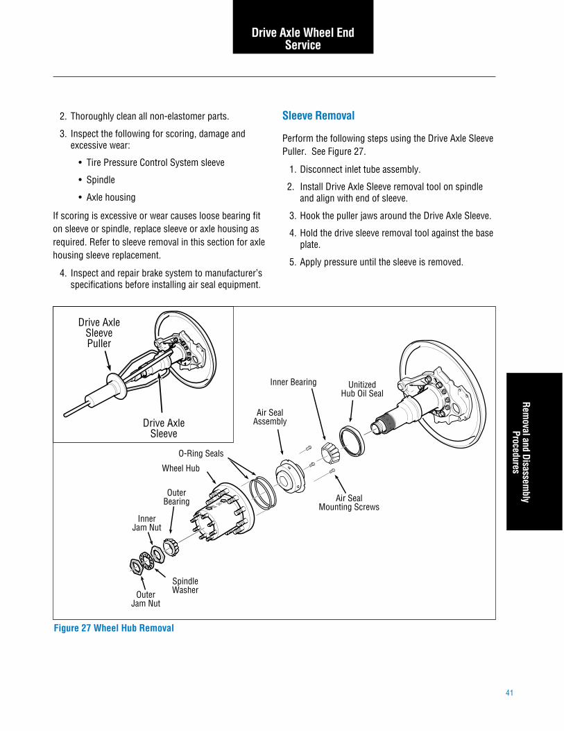
Sleeve Removal
Perform the following steps using the Drive Axle SleevePuller. See Figure 27.
1. Disconnect inlet tube assembly.
2. Install Drive Axle Sleeve removal tool on spindleand align with end of sleeve.
3. Hook the puller jaws around the Drive Axle Sleeve.
4. Hold the drive sleeve removal tool against the baseplate.
5. Apply pressure until the sleeve is removed.
Drive Axle Wheel EndService
Removal and Disassem
blyProcedures
2. Thoroughly clean all non-elastomer parts.
3. Inspect the following for scoring, damage andexcessive wear:
• Tire Pressure Control System sleeve
• Spindle
• Axle housing
If scoring is excessive or wear causes loose bearing fiton sleeve or spindle, replace sleeve or axle housing asrequired. Refer to sleeve removal in this section for axlehousing sleeve replacement.
4. Inspect and repair brake system to manufacturer’sspecifications before installing air seal equipment.
Outer Bearing
Inner Jam Nut
Spindle WasherOuter
Jam Nut
Wheel Hub
OILAIR
O-Ring Seals
Air Seal Assembly
Air Seal Mounting Screws
Unitized Hub Oil Seal
Inner Bearing
Drive Axle
Sleeve
Drive Axle Sleeve Puller
Figure 27 Wheel Hub Removal

42
Drive Axle Wheel EndService
Drive Axle Sleeve
Brake Spider
Spindle
A
B
Figure 28 Spindle Sleeve Depth Measurement
Sleeve Installation
1. Measure the depth of the first step in spindlesleeve to +/– .001". (See Figure 28, dimension “A”)Measure out this distance on the axle spindle’s oilseal area. (See Figure 28, dimension “B”.) Markthis point on spindle.
2. Apply an anti-seizing compound to the sleeve asshown. See Figure 29.
3. Apply lubricant to the sleeve inner O-ring andinstall in groove in large diameter end of sleeve.See Figure 30.
Caution: Do not allow anti-seize to get into airpassages.
4. Apply grease to the inboard sealing surface of theaxle spindle. See Figure 30.
5. Position the sleeve on the axle spindle, makingsure to align the input air port of the sleeve withthe Tire Pressure Control System air line accesshole on the brake flange and spider. See Figure 32.
6. Attach the sleeve installation fixture to the brakespider as follows:
• Install base plate to four threaded rods andagainst welded locating nuts. Secure with flatwashers and nuts. See Figure 32.
!
Drive Axle Sleeve
Sleeve Inner O-ring
Apply Anti-seize
Figure 29 Sleeve Inner O-Ring Installation
!
• Align four threaded rods with holes in brakespider and install. See Figure 32. Secure withflat washers and nuts.
7. Press the sleeve onto the axle spindle as follows:See Figure 32.
• Install mounting cup on spindle and align withend of sleeve.
• Hold the bottle jack against the base plate andpump until jack head engages the other end ofthe installation tube.
• Extend jack until sleeve is bottomed on axlespindle.
Caution: Be sure that the inside end of spindlesleeve is installed far enough to meet mark put onspindle in step 1.
• Retract bottle jack and remove sleeve installa-tion fixture.
8. Lubricate and install O-ring and backup ring intodrive axle sleeve as shown in Figure 31.
Note: Position O-ring and backup ring on spindle. Useouter bearing and hand pressure to press them intoposition.

43
Drive Axle Wheel EndService
Sleeve Installation
Figure 31 Spindle O-Ring and Backup RingFigure 30 Spindle Preparation
Figure 32 Preparation for Sleeve Installation
Drive Axle Sleeve
Spindle
Sleeve Mounting
CupBottle Jack 5T Capacity
Threaded Rod (4)
Base Plate
Locating Nuts
Align Inlet Air Port with Access Hole
Backup Ring
Spindle O-Ring
Drive Axle Sleeve
Apply lubricant here (O-ring sealing surface)
Drive Axle
Spindle

44
Drive Axle Wheel EndService
Install Drive Axle Inlet Tube
1. Install pipe end of 3/8" male NPT to 3/8" flareless tubeend, 45° elbow.
2. Position tube end toward opening of brake flange.Feed drive axle inlet tube through brake flange holeand insert into the tube end of the fitting. The tubemust bottom out in fitting
3. Manually screw nut onto fitting body until fingertight.
4. Make reference mark on nut and tube and tighten nutan additional 13/4 turns.
5. Loosen nut and inspect for proper preset.
Note: A ridge of metal has been raised above the tubesurface, to a height of at least 50% of the thickness of theferrule’s leading edge, completely around the tube. Avoidrotating the ferrule.
Retightening Sequence
If the fitting body was used for ferrule pre-set, retightenthe nut to the same fitting body used earlier in the pre-set.
Air Seal Installation
1. Pre-lube the two hub inner O-rings and install inwheel hub. (See Figure 33.)
2. Install three alignment pins in hub. Alignment pinscan be made of three 8/32 x 1 1/2" screws with headsremoved.
3. Position the air seal assembly (with protectiveguard) in hub and press into place until the flangeis seated against the hub.
• Remove pins.
• Apply removable thread locking compound tothe mounting bolt threads.
• Install the three 8/32 mounting bolts.
4. Pre-lube the inner bearing with the same lubricantused in the axle sump. Place the inner bearing inthe wheel hub.
Figure 33 Wheel Hub Preparation for Installation
1. Install O-ring Seals
3. Position Air Seal Assembly with Protective Guard
OILAIR
Hub Inner O-ring Seals Air
Seal
Oil BearingNew
Inner Bearing
Outer Bearing
2. Install Threaded Alignment Pins
4. Remove Threaded Pins
5. Apply Thread Locking Compound and Install Air Seal Mounting Screws
6. Install Inner Bearing and Unitized Hub Oil Seal
Protective Guard
Air Seal

45
Caution: Use care when applying thin coat ofAeroshell. Make sure not to plug air passageswith lubricant.
2. While insuring that the spindle end will passthrough the air seal protective guard, slide hub intoposition on the spindle and sleeve with one push.
• As the hub is installed, the air seal protectiveguard will be pushed out. Remove the air sealprotective guard.
Caution: Do not pull the hub in and out or rock toinstall. This will cause damage to the air seal.
3. If the hub does not install with the initial push,remove hub from spindle and reposition the airseal protective guard from the inner bearing sideonly. Repeat step 2 for installation.
Note: During installation it may be necessary to use ascrewdriver to align inner bearing with the drivesleeve bearing journal. Be careful not to damageoil seal.
Oil Seal Installation
Using the following tools, install the oil seal in thewheel hub. (See Figure 32.)
• Seal Plate
• Bearing Centering Tool
• Handle Assembly
Caution: Do not hammer directly on the seal!
Wheel Hub InstallationSee Figure 33
Caution: Make sure protective guard is installedin air seal before hub is installed on drive axlesleeve.
1. Apply thin coat of Shell® Aeroshell GR22 orequivalent to the portion of the sleeve where the airseal runs.
Drive Axle Wheel EndService
Air Seal, Wheel Hub and
Oil Seal Installation
!
!
!
!
Figure 34 Wheel Hub Installation
Drive Axle Sleeve
SpindleOuter
Bearing
Inner Jam Nut
Spindle Washer
Outer Jam Nut
Wheel Hub with Air Seal
and Protective Guard Installed
OILAIR
Air Seal Protective Guard (Remove After Hub is in Place
on Sleeve)
Apply thin coat of Shell Aerolube GR22
to this area

46
4. Before installation, lubricate the outer bearing withthe same lubricant used in the axle sump.
Note: Lubricate only with clean axle lubricant of thesame type used in the axle sump. Do not pack thebearings with grease before installation. Grease will
prevent the proper circulation of axle lubricant and maycause wheel seal failure.
5. Install the outer bearing on the spindle.
6. Install the inner nut on the spindle and adjust asfollows:
• Torque the inner nut to 200 lb. ft.(272 N•m) while rotating the hub.
• Loosen the inner nut one full turn.
• Re-torque to 50 lb. ft. (68 N•m) while rotatinghub.
• Back the nut off 1/4 turn.
7. Install the spindle washer. See Figure 35.
• If the dowel pin and washer are not aligned,remove washer, turn it over and reinstall. Ifrequired, loosen the inner nut just enough foralignment.
Drive Axle Wheel EndService
Figure 35 Adjusting Nut Identification
Wheel Bearing Adjusting Nut
(Inner)
Dowel Pin
Spindle Washer
Outer Nut
Figure 36 Sleeve O-Ring Leak Test
2" ID pipe, 12" long
Shop air supply Pressure Gauge
Reservoir
3/4" ID hose 2' long maximum
Valve
Air Port

47
Air Seal, Wheel Hub and
Oil Seal InstallationDrive Axle Wheel End
Service
• Plug hub air port with a 3/8" pipe plug.
• Open the valve from the air supply line andstabilize the pressure in the reservoir to100 ± 5 psig.
• Close air supply valve. Rotate the hub assem-bly while monitoring the pressure gauge. Thepressure reading should not drop more than5 psig in 20 seconds.
Note: If the air leakage exceeds the rate listed previ-ously in step 11, the hub may need to be rotated severaltimes to insure a complete pressure seal.
12. Install axle shaft as follows:
• Place a new gasket on the hub.
• Install the axle shaft.
• Install axle flange tapered bushings (ifrequired).
• Install washers and nuts and tighten to specifictorque.
13. Add two pints of lube to hub at “OIL” fill hole. Donot lube wheel ends by tilting axle.
14. Install oil fill plug in “OIL” hole on hub and tightento 20-30 lbs. ft. (27-40.6 N•m).
Caution: Never tighten the inner nut for align-ment. This will preload the bearing and causepremature failure.
8. Install the outer nut on the spindle and torque asfollows:
• Dowel-type washer lock – 300 lbs. ft.(408 N•m)
• Tang-type washer lock – 250 lbs. ft. (229 N•m)
Note: This adjustment procedure allows the wheel torotate freely with 0.001" to 0.005" (0.025 mm to0.125 mm) end-play.
9. Measure end-play using a dial indicator with a0.001" resolution.
10. Repeat wheel bearing adjustment procedure if end-play is not within specification.
• Disassemble and inspect the components.Replace defective parts and re-assemble.
11. Perform an air pressure check (before oil fill) asfollows (see Figure 36):
• Connect the hose from the 40 in3 pressurereservoir (2" ID x 12" long with 2' max 3/8"hose) to the inlet tube via the male #637° flare.
!

48
Drive Axle Wheel EndService
Wheel and Wheel Valve
Figure 37 is a detailed view of the external air lineconnections on a rear drive wheel.
Note: Perform the following steps with the wheels offthe ground to prevent the tires from losing bead seal.
Install drive axle wheel end pneumatics as follows:
1. Mount inside and outside drive wheels so that bothvalve stems are positioned together and 180° fromthe axle hub air fitting. Feed inner tire hose outthrough wheel edge opening. Position hoses sothey will connect easily to wheel valve as shown inFigure 38. Double check hose alignment.
2. Select two hub mounting studs that will positionwheel valve outlet port 180° from the axle hub airfitting as shown in Figure 37. Remove the nutsand lockwashers on the selected hub studs. Installthe wheel valve mounting bracket and replace thehub lockwashers and nuts.
3. Set wheel valve within mounting bracket and fastento the wheel valve mounting bracket using 3/8" x 1"hex head bolts.
Note: Replace the air filter in wheel valve when the tire
or wheel valve is serviced. See Figure 37.
4. Prepare the wheel valve and hoses in the followingmanner to minimize air loss from the tire whenreinstalling tire hoses.
A. Lubricate O-ring.
B. Secure lock nut against the O-ring washer.
C. Install the tee into the valve until the O-ring isseated and the washer is against the face of thevalve.
D. Back off lock nut.
E. Turn tee clockwise to orient fitting – no more thanone turn.
F. Tighten lock nut 16–19 lbs. ft. (22–26 N•m).
Note: Work quickly to minimize air loss duringsteps 5-8.
5. Remove valve stem core from inner tire, install hoseend on valve stem.
6. Remove valve stem core from outer tire, install hoseend on valve stem.
7. Install outer hose on run tee. Torque to 16–19 lbs. ft.(22–26 N•m)
8. Install inner hose on branch tee. Torque to16–19 lbs. ft. (22–26 N•m)
Figure 37 Run Tee
Locknut O-ring Washer
O-ring Valve

49
Wheel and
Wheel Valve
Drive Axle Wheel EndService
Figure 38 Drive Axle Wheel Air Line Routing
5. Wheel valve mounting bracket
6. 3/8" male 37° flare run tee, 9/16"–18 straight threadO-ring on the run
7. Outer tire hose (short)
1. Inner tire hose (long)
2. 3/8" male 37° flare to 3/8" male pipe fitting
3. Wheel valve control hose
4. Wheel valve
* Note: Align fitting with tire air valve before tightening
to tee 6�
1
2
3
4
5
6 7
To outer tire valve stem*
To inner tire valve stem*
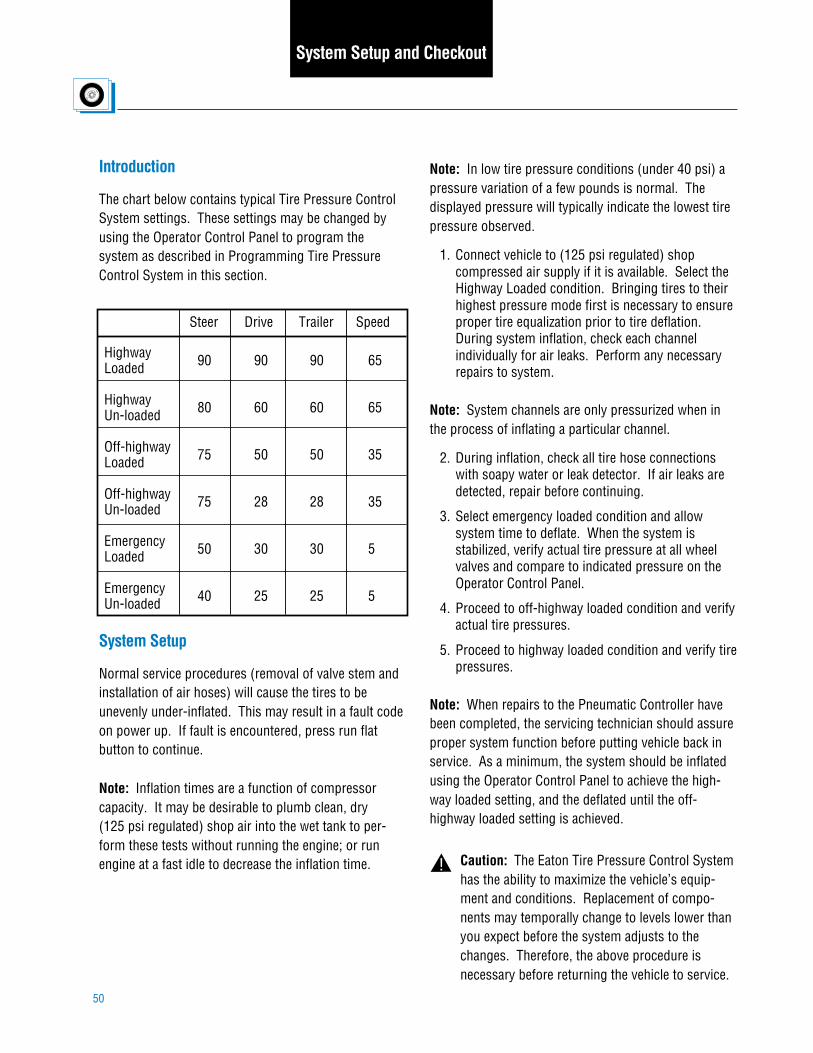
50
Introduction
The chart below contains typical Tire Pressure ControlSystem settings. These settings may be changed byusing the Operator Control Panel to program thesystem as described in Programming Tire PressureControl System in this section.
System Setup
Normal service procedures (removal of valve stem andinstallation of air hoses) will cause the tires to beunevenly under-inflated. This may result in a fault codeon power up. If fault is encountered, press run flatbutton to continue.
Note: Inflation times are a function of compressorcapacity. It may be desirable to plumb clean, dry(125 psi regulated) shop air into the wet tank to per-form these tests without running the engine; or runengine at a fast idle to decrease the inflation time.
Note: In low tire pressure conditions (under 40 psi) apressure variation of a few pounds is normal. Thedisplayed pressure will typically indicate the lowest tirepressure observed.
1. Connect vehicle to (125 psi regulated) shopcompressed air supply if it is available. Select theHighway Loaded condition. Bringing tires to theirhighest pressure mode first is necessary to ensureproper tire equalization prior to tire deflation.During system inflation, check each channelindividually for air leaks. Perform any necessaryrepairs to system.
Note: System channels are only pressurized when inthe process of inflating a particular channel.
2. During inflation, check all tire hose connectionswith soapy water or leak detector. If air leaks aredetected, repair before continuing.
3. Select emergency loaded condition and allowsystem time to deflate. When the system isstabilized, verify actual tire pressure at all wheelvalves and compare to indicated pressure on theOperator Control Panel.
4. Proceed to off-highway loaded condition and verifyactual tire pressures.
5. Proceed to highway loaded condition and verify tirepressures.
Note: When repairs to the Pneumatic Controller havebeen completed, the servicing technician should assureproper system function before putting vehicle back inservice. As a minimum, the system should be inflatedusing the Operator Control Panel to achieve the high-way loaded setting, and the deflated until the off-highway loaded setting is achieved.
Caution: The Eaton Tire Pressure Control Systemhas the ability to maximize the vehicle’s equip-ment and conditions. Replacement of compo-nents may temporally change to levels lower thanyou expect before the system adjusts to thechanges. Therefore, the above procedure isnecessary before returning the vehicle to service.
Highway Loaded Highway Un-loaded Off-highway Loaded Off-highway Un-loaded Emergency Loaded Emergency Un-loaded
90 80 75 75 50 40
90 60 50 28 30 25
90 60 50 28 30 25
65 65 35 35 5 5
Steer Drive Trailer Speed
System Setup and Checkout
!

51
Introduction
The dash-mounted Operator Control Panel is the soleinterface for display of operator information and for keyentry of system instructions. Figure 39 shows theOperator Control Panel. The following sections explainthe purpose and operation of all Operator Control Panelfeatures.
Warning Icons
The two warning icons report operating problems. Youmust take immediate action to either reduce vehiclespeed or check tire condition.
Reduce Vehicle Speed – This signalreports that the vehicle speed is too fastfor the pressure selected. You musteither reduce speed or select a higher
pressure by pressing the appropriate key. Continuedoperation in this mode will result in the system auto-matically selecting a more appropriate pressure setting.
Check Tire Condition – This signalreports that one tire is at a significantlylower pressure than the others and couldindicate that a tire is not holding pres-
sure. The operator should immediately stop the vehicleand identify the extent of tire damage. The system maybe used to re-inflate the low tire if damage is deter-mined to be minimal (e.g., a minor puncture or slowleak) by selecting “RUN FLAT.” The system should notbe used to inflate tires with more substantial damagesuch as large cuts, chunk outs, or structural defects.
mphkph
Figure 39 Operator Control Panel
Operator ControlsSystem
Setup
L/U HWY OFF HWY EMER RUN FLAT
SELECT
mphkph
bar psi
Tire Pressure Control

52
Fault Codes
When an exclamation point (!) follows the digital display, the display is reporting a system fault. The following chartprovides a brief overview of the Tire Pressure Control System fault codes and the affected system.
Fault Code Code Type
1C!
2C!
3C!
4C!
5C!
6C!
7C!
8C!
9C!
10C!
11C!
12C!
13C!
1P!
2P!
3P!
4P!
5P!
6P!
7P!
8P!
9P!
10P!
11P!
No operation Normal operation — Inflate only Inflate only No operation — No operation No operation No operation No operation No operation No operation No operation Inflate only — No operation Pressure check only Pressure check only — Pressure check only Pressure check only Channel inoperative Channel inoperative Channel inoperative
Low power No power down Not assigned Bad connection or no speed signal Bad connection from Electronic Control Unit to Operator Control Panel No pressure transducer reading Too high pressure transducer reading Not assigned Solenoid does not pass electrical diagnostics Solenoid does not pass electrical diagnostics Solenoid does not pass electrical diagnostics Solenoid does not pass electrical diagnostics Solenoid does not Pass electrical diagnostics Solenoid does not pass electrical diagnostics Relay open or shorted No vacuum at Pneumatic Control Unit or in control line Not assigned Unintentional vacuum Slow inflate or deflate Quick loss of pressure Not assigned High pressure switch does not close Wet tank pressure does not rise Vent pressure is outside range Channel loses pressure in inflate mode Channel fails to confirm One tire pressure lower than others
System Status Fault Cause
Power — Speed sensor Control communication Pressure transducer — Steer solenoid Drive solenoid Trailer solenoid Supply solenoid Deflate solenoid Control solenoid Relay No deflate signal — Vacuum fault Channel between modes Pressure read low — Inadequate air pressure Atmospheric Trend fault Tire leak (confirm) Tire leak (imbalance)
Operator Controls
*Note: Refer to Troubleshooting Guide AXTS-0010 for more detailed description of codes.

53
mphkph
bar psi
Tire Pressure Control
bar psi
Digital Display
The display shows either tire pressure or fault codes forthe channel indicated by the illuminated inner tire rings(see Channel Indicators). When the system is activelychanging tire pressure on the selected channel, a“bubble” display in clockwise rotation indicates inflationand counterclockwise indicates deflation.
Fault Indication – The exclamation point indicates thatthe value shown in the digital display is not a pressurebut rather a fault code. See Fault Codes Section.
Metric/English Indicator – This unit of measureindicator tells if the tire pressure is shown in metric(bar) or English (psi) units.
Mode Keys and Annunciator Arrows
These keys select pressures appropriate for differentsurface and loading conditions. The annunciator arrowpoints to the selected key and signals one of two states:
• If the arrow is flashing – the system is in theprocess of checking or changing pressures.
• If the arrow is lighted steady – the selectedpressure has been achieved and the system isde-pressurized.
L/U Key (Loaded/Unloaded) – This key selects pressuresappropriate for either a loaded or unloaded vehicle.
HWY – For high speed travel on paved surfaces.
OFF HWY – For operation on secondary roads.
EMER – For selection of extremely low tire pressures tohelp free a stuck vehicle. Operation in “EMER” modefor longer than 10 minutes will result in the systemautomatically selecting the OFF HWY mode and inflatingthe tires accordingly.
IMPORTANT: The EMER key is for extreme condi-tions only and should not be used for normaldriving.
mphkph
bar psi
Tire Pressure Control
HWY OFF HWY EMERL/U
Operator ControlsFault Codes
!
mphkph
bar psi
Tire Pressure Control
!
Loaded Indicator
The small arrow pointing to the drive wheels indicateswhether you have selected loaded or unloaded pres-sures. You must select loaded if your vehicle is carry-ing any load.
Caution: Operating a loaded vehicle at unloadedtire pressures may result in tire overheating andreduced tire life or blowout.
Run Flat Indicator
This asterisk matches the symbol on the “Run Flat” keyand it indicates that the Run Flat feature is selected.

54
Configuration Indicators
The tractor/trailer outline show(s) whether the vehicleis configured with a two channel (tractor or straighttruck) or three channel (tractor and trailer) Tire Pres-sure Control System.
Channel Indicators
The rings inside the tires of the configuration indicatorsshow which channel (steers, drives or trailers) is beingreported by the digital display.
Eaton Logomark
Indicates power on at vehicle start-up.
Tire Pressure Controlmph
kphbar psi
Tire Pressure Control
mphkph
bar psi
Tire Pressure ControlTire Pressure Control
Run Flat Key
This key allows the operator to over-ride the 11P! (tireleak imbalance) fault. (See Check Tire Condition underWarning Icons in this section.) This key also instructsthe system to check tire pressures at more frequentintervals. The “RUN FLAT” feature will automatically de-select after 10 minutes.
Select Key
This key allows the operator to continuously monitorone channel, or scan all of them. On power-up, theOperator Control Panel will not display any pressures(“Quiet Mode”). Pressing the select key once will causethe display to scan the tire pressures (see ChannelIndicators). Repeated pressing will lock the display oneach individual channel (so that any channel may bemonitored continuously) and then return to the nodisplay condition.
Note: All symbols on the display will light momentarilyupon start of the vehicle.
Operator Controls
RUN FLATL/U HWY OFF HWY EMER
SELECT
mphkph
bar psi
Tire Pressure Control
mphkph
bar psi
Tire Pressure Control
RUN FLATL/U HWY OFF HWY EMER
SELECTmph
kphbar psi
Tire Pressure Control

55
Tire Pressure Control System Programming
Eaton’s Tire Pressure Control System features onlocation programming through the Operator ControlPanel. Programmable settings include:
• Individual pressure settings for the steer, driveand trailer axles.
• Loaded and unloaded axle programming forhighway, off highway and emergency condi-tions.
• Overspeed warning for highway, off highwayor emergency conditions.
Enter the Tire Pressure Control System programmingsequence by pressing the SELECT and L/U buttons atthe same time. A flashing bar or psi verifies that youare in the programming mode and also indicates thatthe first selection, English or metric values, is ready forprogramming. Refer to Figure 40 for sample proce-dure.
Press up/down arrows to select options or changesettings (pressure or speed) and press SELECT buttonto record a selection in memory and move to the nextstep.
Press the SELECT button repeatedly to move throughthe program steps, one step for each time the SELECTbutton is pressed. Refer to the programming referencechart for specific Tire Pressure Control System pres-sure and speed programming steps.
To complete the programming sequence, or exit theprogramming mode, continue to press SELECT buttonto step through to the end of the procedure.
Note: If no buttons are pressed for more than oneminute, the Operator Control Panel will end the pro-gramming sequence, saving any changes made duringprogramming.
Tire PressureControl System
Programm
ingOperator Controls
Tire Pressure ControlSystem
Programm
ing

56
Figure 40 Entering the Programming Sequence
Operator Controls
mphkph
bar psi
Tire Pressure Control
mphkph
bar psi
Tire Pressure Control
bar psiL /U SELECT
+
flashing “bar” or “psi” indicates you have
entered programming
Press at the same time to enter programming
L/U
orPress to record a selection in memory and move to the next step
Toggle between metric
and English
EMER
Make selection
SELECT
L /U
+
Press at the same time to exit
programming
SELECT
bar psi
L /U SELECT
Enter programming
SELECT
+SELECT L /U
orEMER
Press SELECT six times to go to step 7Press to set highway
unloaded drive pressure
L/U SELECT
Exit programming
Example for Step 7 Programming (see programming quick reference chart)
SELECT
+SELECT
+ +SELECT
+SELECT
+SELECT
+
+
down arrow
up arrow
Example for Step 1 Programming (see programming quick reference chart)
down arrow
up arrow

57
Programming Quick Reference Chart
Step Setting
1
2
3
4
5
6
7
8
9
10
11
12
13
14
15
16
17
18
19
20
21
22
Metric English
Indicator
Speed Indicator Hwy Off Hwy Emer
Loaded Arrow
Steer Drive Trailer
Metric/English
Highway Overspeed
Highway Loaded Steer Pressure
Highway Loaded Drive Pressure
Highway Loaded Trailer Pressure
Highway Unloaded
Steer Pressure
Highway Unloaded Drive Pressure
Highway Unloaded
Trailer Pressure
Off-Highway Overspeed
Off-Highway Loaded Steer Pressure
Off-Highway Loaded
Drive Pressure
Off-Highway Loaded Trailer Pressure
Off-Highway Unloaded
Steer Pressure
Off-Highway Unloaded Drive Pressure
Off-Highway Unloaded
Trailer Pressure
Emergency Overspeed
Emergency Loaded Steer Pressure
Emergency Loaded
Drive Pressure
Emergency Loaded Trailer Pressure
Emergency Unloaded
Steer Pressure
Emergency Unloaded Drive Pressure
Emergency Unloaded
Trailer Pressure
On
On
On
On
On
On
On
On
On
On
On
On
On
On
On
On
On
On
On
On
On
On
On
On
On
On
On
On
On
On
On
On
On
On
On
On
On
On
On
On
On
On
On
On
On
On
On
On
On
On
On
On
Annunciator Arrows Channel Indicator
Figure 41 Entering the Programming Sequence Chart
Operator ControlsProgram
ming Quick
Reference Chart

58
Figure 42 Fastener Torques
Fastener Torques
Fastener Oil Fill Plug – (drive hub) Rotary Joint Banjo Bolt Cap Screws (hubcap) Wheel Valve Retaining Bolt Locknut on Wheel Valve Run Tee Inner/Outer Hose – to Tee Control Hose – to Wheel Valve Pressure Transducer Cover Fasteners – Pneumatic Control Unit Wheel Bearing End Play – .001 to .005" (0.025 mm to 0.125 mm)
lbs. ft. 20–30 31 140–160 lbs. in. 15 15 16–19 16–19 16–19 10–12 35–45 lbs. in.
N•m 26–40.6 42 15.8–18.1 20 20 22–26 22–26 22–26 14–16 4–6

59
Appendix A

For spec’ing or service assistance, call 1-800-826-HELP (4357) 24 hours a day, 7 days a week (Mexico:001-800-826-4357), for more time on the road. Or visit our web site at www.roadranger.com.
Roadranger: Eaton, Dana and other trusted partners providing the best products and services in the industry, ensuring more time on the road.
©2007 Eaton Corporation and Dana Corporation All rights reserved. Printed in USA · AXSM0010
Spicer® TPCS (Tire Pressure Control System)
Copyright Eaton and Dana Corporation,2007. EATON AND DANA CORPORATIONhereby grants its customers, vendors, ordistributors permission to freely copy,reproduce and/or distribute this documentin printed format. THIS INFORMATION ISNOT INTENDED FOR SALE OR RESALE,AND THIS NOTICE MUST REMAINON ALL COPIES.
Dana Corporation Commercial Vehicle Systems P.O. Box 4097 Kalamazoo, MI 49003 U.S.A. www.roadranger.com •• • • •