Embed Size (px)
Citation preview
HEALTH IMAGING
© Eastman Kodak Company
Publication No. SM3226-129AUG97
Supersedes SM3226-110FEB97
SERVICE MANUALfor the
Kodak Ektascan 1120 LASER PRINTER
H129_0710AC

2 29AUG97 – SM3226-1
PLEASE NOTE The information contained herein is based on the experience and knowledge relating to thesubject matter gained by Eastman Kodak Company prior to publication.
No patent license is granted by this information.
Eastman Kodak Company reserves the right to change this information without notice, andmakes no warranty, express or implied, with respect to this information. Kodak shall not beliable for any loss or damage, including consequential or special damages, resulting from anyuse of this information, even if loss or damage is caused by Kodak’s negligence or other fault.
This equipment includes parts and assemblies sensitive to damage from electrostaticdischarge. Use caution to prevent damage during all service procedures.
ImportantUse qualified personnel to service this equipment.
WarningDANGER - Infrared Laser Beam is not visible. Laser radiation when open, avoid direct exposure to infraredbeam. Use of controls or adjustments or performance of procedures other than those specified herin may result inhazardous radiation exposure.

SM3226-1 – 29AUG97 –3
Description Page
Table of Contents
Service Requirements . . . . . . . . . . . . . . . . . . . . . . . . . . . . . . . . . . . . . . . . . . . . . . . . . . . . 1-1Safety. . . . . . . . . . . . . . . . . . . . . . . . . . . . . . . . . . . . . . . . . . . . . . . . . . . . . . . . . . . . . . 1-2Special Tools . . . . . . . . . . . . . . . . . . . . . . . . . . . . . . . . . . . . . . . . . . . . . . . . . . . . . . . . 1-3
Removals . . . . . . . . . . . . . . . . . . . . . . . . . . . . . . . . . . . . . . . . . . . . . . . . . . . . . . . . . . . . . . 2-1Covers . . . . . . . . . . . . . . . . . . . . . . . . . . . . . . . . . . . . . . . . . . . . . . . . . . . . . . . . . . . . . 2-2 Right, Left and Back Control Unit Covers. . . . . . . . . . . . . . . . . . . . . . . . . . . . . . 2-2
Front Control Unit Cover . . . . . . . . . . . . . . . . . . . . . . . . . . . . . . . . . . . . . . . . . . 2-2Right and Back Image Unit Covers . . . . . . . . . . . . . . . . . . . . . . . . . . . . . . . . . . 2-3Left Image Unit Cover . . . . . . . . . . . . . . . . . . . . . . . . . . . . . . . . . . . . . . . . . . . . 2-3Sequence Board Shield . . . . . . . . . . . . . . . . . . . . . . . . . . . . . . . . . . . . . . . . . . . . 2-4Supply Magazine Door, Receive Magazine Door, and User Access Door . . . . . 2-4Top Cover . . . . . . . . . . . . . . . . . . . . . . . . . . . . . . . . . . . . . . . . . . . . . . . . . . . . . . 2-5Right Inside Cover . . . . . . . . . . . . . . . . . . . . . . . . . . . . . . . . . . . . . . . . . . . . . . . 2-6Left Inside Cover . . . . . . . . . . . . . . . . . . . . . . . . . . . . . . . . . . . . . . . . . . . . . . . . 2-6
Circuit Boards . . . . . . . . . . . . . . . . . . . . . . . . . . . . . . . . . . . . . . . . . . . . . . . . . . . . . . . 2-7 Memory Board/6MB or 20MB. . . . . . . . . . . . . . . . . . . . . . . . . . . . . . . . . . . . . . . 2-7
System Controller Board . . . . . . . . . . . . . . . . . . . . . . . . . . . . . . . . . . . . . . . . . . 2-8Print Controller Board . . . . . . . . . . . . . . . . . . . . . . . . . . . . . . . . . . . . . . . . . . . . 2-10Driver Board . . . . . . . . . . . . . . . . . . . . . . . . . . . . . . . . . . . . . . . . . . . . . . . . . . . . 2-12
JUMPERS . . . . . . . . . . . . . . . . . . . . . . . . . . . . . . . . . . . . . . . . . . . . . . . . . . 2-13SWITCHES . . . . . . . . . . . . . . . . . . . . . . . . . . . . . . . . . . . . . . . . . . . . . . . . . 2-13The Replacement of a Driver Board with a Universal Driver Board . . . . . 2-14
2-Phase Pulse Motor Driver Boards (2PMD) . . . . . . . . . . . . . . . . . . . . . . . . . . . 2-175-Phase Pulse Motor Driver Boards (5PMD) . . . . . . . . . . . . . . . . . . . . . . . . . . . 2-18Sequence Board . . . . . . . . . . . . . . . . . . . . . . . . . . . . . . . . . . . . . . . . . . . . . . . . . 2-19Slow Scan Motor Board . . . . . . . . . . . . . . . . . . . . . . . . . . . . . . . . . . . . . . . . . . . 2-22Laser Diode Power Supply Board . . . . . . . . . . . . . . . . . . . . . . . . . . . . . . . . . . . 2-23Backplane Board . . . . . . . . . . . . . . . . . . . . . . . . . . . . . . . . . . . . . . . . . . . . . . . . 2-25
Control Unit Components . . . . . . . . . . . . . . . . . . . . . . . . . . . . . . . . . . . . . . . . . . . . . . 2-26 Exhaust Fans . . . . . . . . . . . . . . . . . . . . . . . . . . . . . . . . . . . . . . . . . . . . . . . . . . . . 2-26
Intake Fans . . . . . . . . . . . . . . . . . . . . . . . . . . . . . . . . . . . . . . . . . . . . . . . . . . . . . 2-27Main Power Supply . . . . . . . . . . . . . . . . . . . . . . . . . . . . . . . . . . . . . . . . . . . . . . 2-28
Image Unit Components . . . . . . . . . . . . . . . . . . . . . . . . . . . . . . . . . . . . . . . . . . . . . . . 2-29 Optical Unit . . . . . . . . . . . . . . . . . . . . . . . . . . . . . . . . . . . . . . . . . . . . . . . . . . . . . 2-29
Optical Unit Components . . . . . . . . . . . . . . . . . . . . . . . . . . . . . . . . . . . . . . . . . . 2-33R Transportation Roller Assembly . . . . . . . . . . . . . . . . . . . . . . . . . . . . . . . . . . . 2-34S Transportation Roller Assembly . . . . . . . . . . . . . . . . . . . . . . . . . . . . . . . . . . . 2-35Outlet Guide Plate Assembly . . . . . . . . . . . . . . . . . . . . . . . . . . . . . . . . . . . . . . . 2-36Slow Scan and Encoder Assembly . . . . . . . . . . . . . . . . . . . . . . . . . . . . . . . . . . . 2-39Slow Scan Assembly Components . . . . . . . . . . . . . . . . . . . . . . . . . . . . . . . . . . . 2-41Supply Magazine Open/Close Assembly with Separation Unit . . . . . . . . . . . . . 2-42Supply Magazine Open/Close Assembly Components . . . . . . . . . . . . . . . . . . . 2-44Separation Assembly . . . . . . . . . . . . . . . . . . . . . . . . . . . . . . . . . . . . . . . . . . . . . 2-44Separation Assembly Components . . . . . . . . . . . . . . . . . . . . . . . . . . . . . . . . . . . 2-46Receive Magazine Open/Close Assembly . . . . . . . . . . . . . . . . . . . . . . . . . . . . . 2-48R Magazine Storing Case . . . . . . . . . . . . . . . . . . . . . . . . . . . . . . . . . . . . . . . . . . 2-49Locating Film Transportation Components . . . . . . . . . . . . . . . . . . . . . . . . . . . . 2-51Receive Roller Motor . . . . . . . . . . . . . . . . . . . . . . . . . . . . . . . . . . . . . . . . . . . . . 2-52Transport Roller Motor . . . . . . . . . . . . . . . . . . . . . . . . . . . . . . . . . . . . . . . . . . . 2-53Supply Roller Motor . . . . . . . . . . . . . . . . . . . . . . . . . . . . . . . . . . . . . . . . . . . . . . 2-54
SERVICE MANUAL
–4 29AUG97 – SM3226-1
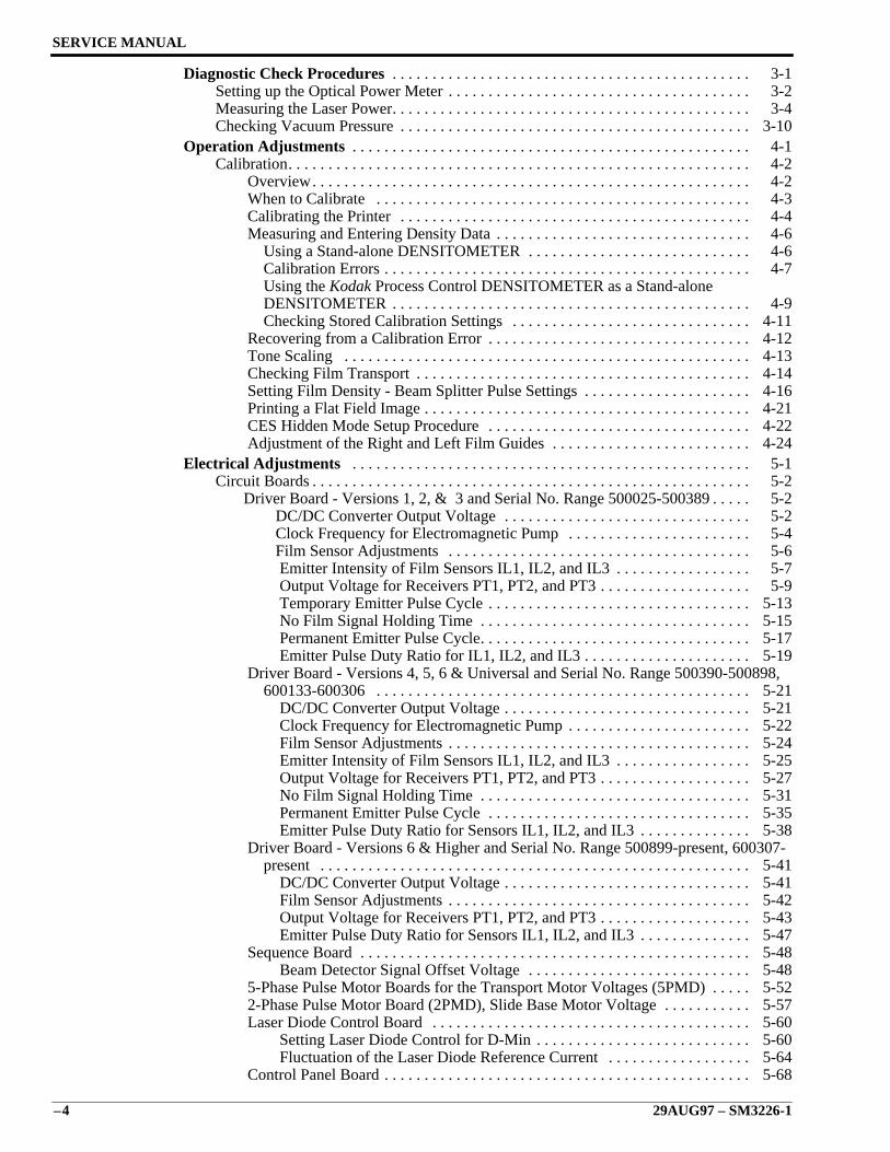
Diagnostic Check Procedures . . . . . . . . . . . . . . . . . . . . . . . . . . . . . . . . . . . . . . . . . . . . . 3-1Setting up the Optical Power Meter . . . . . . . . . . . . . . . . . . . . . . . . . . . . . . . . . . . . . . 3-2Measuring the Laser Power. . . . . . . . . . . . . . . . . . . . . . . . . . . . . . . . . . . . . . . . . . . . . 3-4Checking Vacuum Pressure . . . . . . . . . . . . . . . . . . . . . . . . . . . . . . . . . . . . . . . . . . . . 3-10
Operation Adjustments . . . . . . . . . . . . . . . . . . . . . . . . . . . . . . . . . . . . . . . . . . . . . . . . . . 4-1Calibration. . . . . . . . . . . . . . . . . . . . . . . . . . . . . . . . . . . . . . . . . . . . . . . . . . . . . . . . . . 4-2 Overview. . . . . . . . . . . . . . . . . . . . . . . . . . . . . . . . . . . . . . . . . . . . . . . . . . . . . . . 4-2
When to Calibrate . . . . . . . . . . . . . . . . . . . . . . . . . . . . . . . . . . . . . . . . . . . . . . . 4-3Calibrating the Printer . . . . . . . . . . . . . . . . . . . . . . . . . . . . . . . . . . . . . . . . . . . . 4-4Measuring and Entering Density Data . . . . . . . . . . . . . . . . . . . . . . . . . . . . . . . . 4-6 Using a Stand-alone DENSITOMETER . . . . . . . . . . . . . . . . . . . . . . . . . . . . 4-6 Calibration Errors . . . . . . . . . . . . . . . . . . . . . . . . . . . . . . . . . . . . . . . . . . . . . . 4-7 Using the Kodak Process Control DENSITOMETER as a Stand-alone
DENSITOMETER . . . . . . . . . . . . . . . . . . . . . . . . . . . . . . . . . . . . . . . . . . . . . 4-9 Checking Stored Calibration Settings . . . . . . . . . . . . . . . . . . . . . . . . . . . . . . 4-11Recovering from a Calibration Error . . . . . . . . . . . . . . . . . . . . . . . . . . . . . . . . . 4-12Tone Scaling . . . . . . . . . . . . . . . . . . . . . . . . . . . . . . . . . . . . . . . . . . . . . . . . . . . 4-13Checking Film Transport . . . . . . . . . . . . . . . . . . . . . . . . . . . . . . . . . . . . . . . . . . 4-14Setting Film Density - Beam Splitter Pulse Settings . . . . . . . . . . . . . . . . . . . . . 4-16Printing a Flat Field Image . . . . . . . . . . . . . . . . . . . . . . . . . . . . . . . . . . . . . . . . . 4-21CES Hidden Mode Setup Procedure . . . . . . . . . . . . . . . . . . . . . . . . . . . . . . . . . 4-22Adjustment of the Right and Left Film Guides . . . . . . . . . . . . . . . . . . . . . . . . . 4-24
Electrical Adjustments . . . . . . . . . . . . . . . . . . . . . . . . . . . . . . . . . . . . . . . . . . . . . . . . . . 5-1Circuit Boards . . . . . . . . . . . . . . . . . . . . . . . . . . . . . . . . . . . . . . . . . . . . . . . . . . . . . . . 5-2 Driver Board - Versions 1, 2, & 3 and Serial No. Range 500025-500389 . . . . . 5-2
DC/DC Converter Output Voltage . . . . . . . . . . . . . . . . . . . . . . . . . . . . . . . 5-2 Clock Frequency for Electromagnetic Pump . . . . . . . . . . . . . . . . . . . . . . . 5-4 Film Sensor Adjustments . . . . . . . . . . . . . . . . . . . . . . . . . . . . . . . . . . . . . . 5-6
Emitter Intensity of Film Sensors IL1, IL2, and IL3 . . . . . . . . . . . . . . . . . 5-7 Output Voltage for Receivers PT1, PT2, and PT3 . . . . . . . . . . . . . . . . . . . 5-9
Temporary Emitter Pulse Cycle . . . . . . . . . . . . . . . . . . . . . . . . . . . . . . . . . 5-13No Film Signal Holding Time . . . . . . . . . . . . . . . . . . . . . . . . . . . . . . . . . . 5-15Permanent Emitter Pulse Cycle. . . . . . . . . . . . . . . . . . . . . . . . . . . . . . . . . . 5-17Emitter Pulse Duty Ratio for IL1, IL2, and IL3 . . . . . . . . . . . . . . . . . . . . . 5-19
Driver Board - Versions 4, 5, 6 & Universal and Serial No. Range 500390-500898,600133-600306 . . . . . . . . . . . . . . . . . . . . . . . . . . . . . . . . . . . . . . . . . . . . . . . 5-21
DC/DC Converter Output Voltage . . . . . . . . . . . . . . . . . . . . . . . . . . . . . . . 5-21 Clock Frequency for Electromagnetic Pump . . . . . . . . . . . . . . . . . . . . . . . 5-22 Film Sensor Adjustments . . . . . . . . . . . . . . . . . . . . . . . . . . . . . . . . . . . . . . 5-24 Emitter Intensity of Film Sensors IL1, IL2, and IL3 . . . . . . . . . . . . . . . . . 5-25 Output Voltage for Receivers PT1, PT2, and PT3 . . . . . . . . . . . . . . . . . . . 5-27 No Film Signal Holding Time . . . . . . . . . . . . . . . . . . . . . . . . . . . . . . . . . . 5-31 Permanent Emitter Pulse Cycle . . . . . . . . . . . . . . . . . . . . . . . . . . . . . . . . . 5-35 Emitter Pulse Duty Ratio for Sensors IL1, IL2, and IL3 . . . . . . . . . . . . . . 5-38Driver Board - Versions 6 & Higher and Serial No. Range 500899-present, 600307-
present . . . . . . . . . . . . . . . . . . . . . . . . . . . . . . . . . . . . . . . . . . . . . . . . . . . . . . 5-41 DC/DC Converter Output Voltage . . . . . . . . . . . . . . . . . . . . . . . . . . . . . . . 5-41 Film Sensor Adjustments . . . . . . . . . . . . . . . . . . . . . . . . . . . . . . . . . . . . . . 5-42 Output Voltage for Receivers PT1, PT2, and PT3 . . . . . . . . . . . . . . . . . . . 5-43 Emitter Pulse Duty Ratio for Sensors IL1, IL2, and IL3 . . . . . . . . . . . . . . 5-47Sequence Board . . . . . . . . . . . . . . . . . . . . . . . . . . . . . . . . . . . . . . . . . . . . . . . . . 5-48 Beam Detector Signal Offset Voltage . . . . . . . . . . . . . . . . . . . . . . . . . . . . 5-485-Phase Pulse Motor Boards for the Transport Motor Voltages (5PMD) . . . . . 5-522-Phase Pulse Motor Board (2PMD), Slide Base Motor Voltage . . . . . . . . . . . 5-57Laser Diode Control Board . . . . . . . . . . . . . . . . . . . . . . . . . . . . . . . . . . . . . . . . 5-60 Setting Laser Diode Control for D-Min . . . . . . . . . . . . . . . . . . . . . . . . . . . 5-60 Fluctuation of the Laser Diode Reference Current . . . . . . . . . . . . . . . . . . 5-64Control Panel Board . . . . . . . . . . . . . . . . . . . . . . . . . . . . . . . . . . . . . . . . . . . . . . 5-68

SM3226-1 – 29AUG97 –5
Sensors. . . . . . . . . . . . . . . . . . . . . . . . . . . . . . . . . . . . . . . . . . . . . . . . . . . . . . . . . . . . . 5-70 Sucker Pad Height . . . . . . . . . . . . . . . . . . . . . . . . . . . . . . . . . . . . . . . . . . . . . . . . 5-70
PHF Film Suction Sensor . . . . . . . . . . . . . . . . . . . . . . . . . . . . . . . . . . . . . . . . . . 5-74PHS1 S Magazine Open Sensor . . . . . . . . . . . . . . . . . . . . . . . . . . . . . . . . . . . . . 5-76PHS2 S Magazine Close Sensor . . . . . . . . . . . . . . . . . . . . . . . . . . . . . . . . . . . . . 5-78PH3 S Magazine Door Sensor . . . . . . . . . . . . . . . . . . . . . . . . . . . . . . . . . . . . . . 5-80CHS1 Slide Base Position Sensor Reference Position . . . . . . . . . . . . . . . . . . . . 5-81PHR1 R Magazine Open Sensor . . . . . . . . . . . . . . . . . . . . . . . . . . . . . . . . . . . . 5-86PHR2 R Magazine Close Sensor . . . . . . . . . . . . . . . . . . . . . . . . . . . . . . . . . . . . 5-88PH4 R Magazine Door Sensor . . . . . . . . . . . . . . . . . . . . . . . . . . . . . . . . . . . . . . 5-90Receive Side Stopper Position . . . . . . . . . . . . . . . . . . . . . . . . . . . . . . . . . . . . . . 5-91CHT1 Supply Roller Position Sensor . . . . . . . . . . . . . . . . . . . . . . . . . . . . . . . . . 5-93CHT2 Receive Roller Position Sensor . . . . . . . . . . . . . . . . . . . . . . . . . . . . . . . . 5-97
Preventive Maintenance Checklist . . . . . . . . . . . . . . . . . . . . . . . . . . . . . . . . . . . . . . . . . 6-1

SERVICE MANUAL
–6 29AUG97 – SM3226-1

Service Requirements
SM3226-1 – 29AUG97 1–1
Section 1: Service Requirements
Description Page
Table of Contents
Safety. . . . . . . . . . . . . . . . . . . . . . . . . . . . . . . . . . . . . . . . . . . . . . . . . . . . . . . . . . . . . . 1-2Special Tools . . . . . . . . . . . . . . . . . . . . . . . . . . . . . . . . . . . . . . . . . . . . . . . . . . . . . . . . 1-3
SERVICE MANUAL
1–2 29AUG97 – SM3226-1
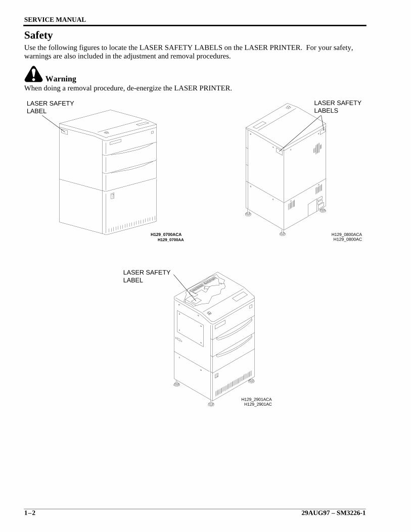
SafetyUse the following figures to locate the LASER SAFETY LABELS on the LASER PRINTER. For your safety,warnings are also included in the adjustment and removal procedures.
WarningWhen doing a removal procedure, de-energize the LASER PRINTER.
H129_0700AA
LASER SAFETYLABEL
H129_0700ACAH129_0800AC
H129_0800ACA
LABELSLASER SAFETY
H129_2901ACH129_2901ACA
LABELLASER SAFETY
Service Requirements
SM3226-1 – 29AUG97 1–3
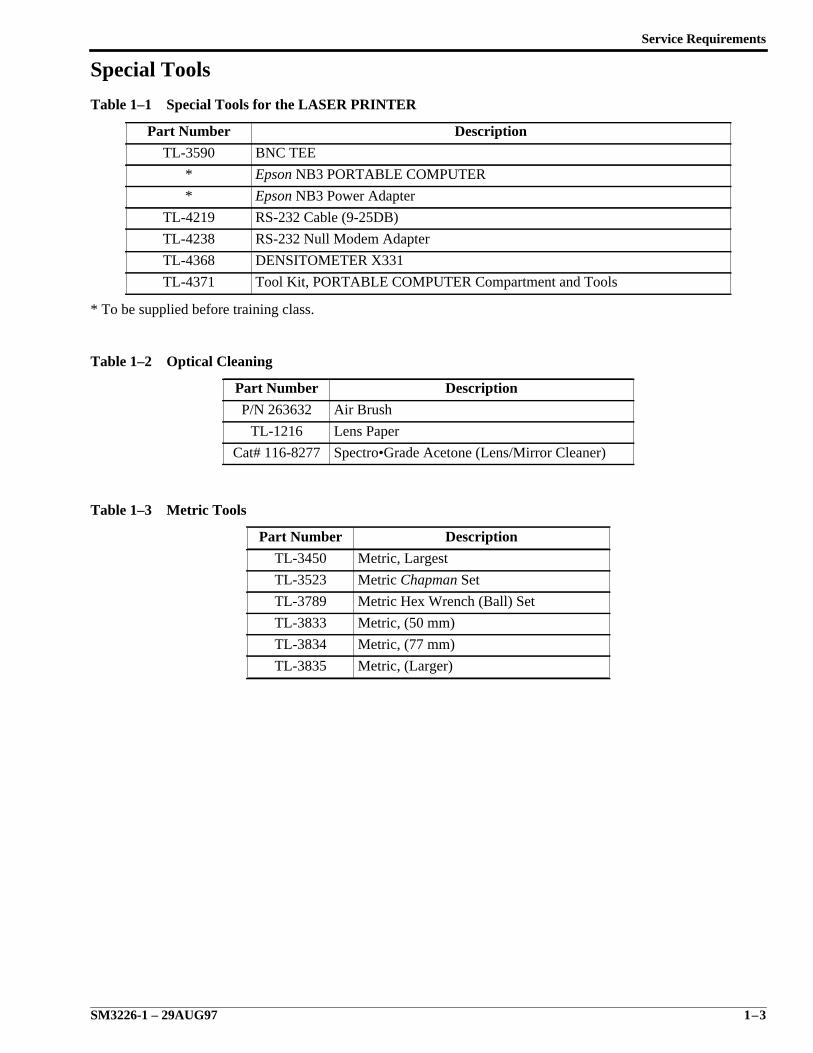
Special Tools
Table 1–1 Special Tools for the LASER PRINTER
* To be supplied before training class.
Table 1–2 Optical Cleaning
Table 1–3 Metric Tools
Part Number Description
TL-3590 BNC TEE
* Epson NB3 PORTABLE COMPUTER
* Epson NB3 Power Adapter
TL-4219 RS-232 Cable (9-25DB)
TL-4238 RS-232 Null Modem Adapter
TL-4368 DENSITOMETER X331
TL-4371 Tool Kit, PORTABLE COMPUTER Compartment and Tools
Part Number Description
P/N 263632 Air Brush
TL-1216 Lens Paper
Cat# 116-8277 Spectro•Grade Acetone (Lens/Mirror Cleaner)
Part Number Description
TL-3450 Metric, Largest
TL-3523 Metric Chapman Set
TL-3789 Metric Hex Wrench (Ball) Set
TL-3833 Metric, (50 mm)
TL-3834 Metric, (77 mm)
TL-3835 Metric, (Larger)
SERVICE MANUAL
1–4 29AUG97 – SM3226-1
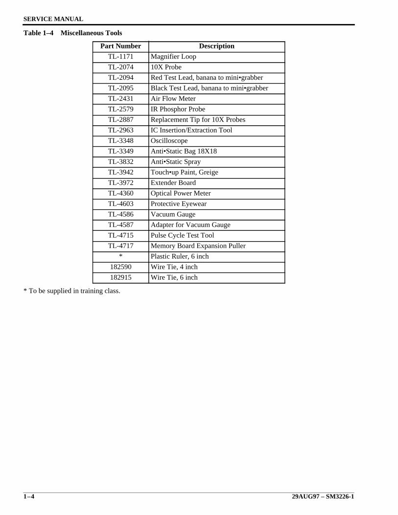
Table 1–4 Miscellaneous Tools
* To be supplied in training class.
Part Number Description
TL-1171 Magnifier Loop
TL-2074 10X Probe
TL-2094 Red Test Lead, banana to mini•grabber
TL-2095 Black Test Lead, banana to mini•grabber
TL-2431 Air Flow Meter
TL-2579 IR Phosphor Probe
TL-2887 Replacement Tip for 10X Probes
TL-2963 IC Insertion/Extraction Tool
TL-3348 Oscilloscope
TL-3349 Anti•Static Bag 18X18
TL-3832 Anti•Static Spray
TL-3942 Touch•up Paint, Greige
TL-3972 Extender Board
TL-4360 Optical Power Meter
TL-4603 Protective Eyewear
TL-4586 Vacuum Gauge
TL-4587 Adapter for Vacuum Gauge
TL-4715 Pulse Cycle Test Tool
TL-4717 Memory Board Expansion Puller
* Plastic Ruler, 6 inch
182590 Wire Tie, 4 inch
182915 Wire Tie, 6 inch
Removals
SM3226-1 – 29AUG97 2–1
Section 2: Removals
Description Page
Table of Contents
Covers . . . . . . . . . . . . . . . . . . . . . . . . . . . . . . . . . . . . . . . . . . . . . . . . . . . . . . . . . . . . . 2-2 Right, Left and Back Control Unit Covers. . . . . . . . . . . . . . . . . . . . . . . . . . . . . . 2-2
Front Control Unit Cover . . . . . . . . . . . . . . . . . . . . . . . . . . . . . . . . . . . . . . . . . . 2-2Right and Back Image Unit Covers . . . . . . . . . . . . . . . . . . . . . . . . . . . . . . . . . . 2-3Left Image Unit Cover . . . . . . . . . . . . . . . . . . . . . . . . . . . . . . . . . . . . . . . . . . . . 2-3Sequence Board Shield . . . . . . . . . . . . . . . . . . . . . . . . . . . . . . . . . . . . . . . . . . . . 2-4Supply Magazine Door, Receive Magazine Door, and User Access Door . . . . . 2-4Top Cover . . . . . . . . . . . . . . . . . . . . . . . . . . . . . . . . . . . . . . . . . . . . . . . . . . . . . . 2-5Right Inside Cover . . . . . . . . . . . . . . . . . . . . . . . . . . . . . . . . . . . . . . . . . . . . . . . 2-6Left Inside Cover . . . . . . . . . . . . . . . . . . . . . . . . . . . . . . . . . . . . . . . . . . . . . . . . 2-6
Circuit Boards . . . . . . . . . . . . . . . . . . . . . . . . . . . . . . . . . . . . . . . . . . . . . . . . . . . . . . . 2-7 Memory Board/6MB or 20MB. . . . . . . . . . . . . . . . . . . . . . . . . . . . . . . . . . . . . . . 2-7
System Controller Board . . . . . . . . . . . . . . . . . . . . . . . . . . . . . . . . . . . . . . . . . . 2-8Print Controller Board . . . . . . . . . . . . . . . . . . . . . . . . . . . . . . . . . . . . . . . . . . . . 2-10Driver Board . . . . . . . . . . . . . . . . . . . . . . . . . . . . . . . . . . . . . . . . . . . . . . . . . . . . 2-12
JUMPERS . . . . . . . . . . . . . . . . . . . . . . . . . . . . . . . . . . . . . . . . . . . . . . . . . . 2-13SWITCHES . . . . . . . . . . . . . . . . . . . . . . . . . . . . . . . . . . . . . . . . . . . . . . . . . 2-13The Replacement of a Driver Board with a Universal Driver Board . . . . . 2-14
2-Phase Pulse Motor Driver Boards (2PMD) . . . . . . . . . . . . . . . . . . . . . . . . . . . 2-175-Phase Pulse Motor Driver Boards (5PMD) . . . . . . . . . . . . . . . . . . . . . . . . . . . 2-18Sequence Board . . . . . . . . . . . . . . . . . . . . . . . . . . . . . . . . . . . . . . . . . . . . . . . . . 2-19Slow Scan Motor Board . . . . . . . . . . . . . . . . . . . . . . . . . . . . . . . . . . . . . . . . . . . 2-22Laser Diode Power Supply Board . . . . . . . . . . . . . . . . . . . . . . . . . . . . . . . . . . . 2-23Backplane Board . . . . . . . . . . . . . . . . . . . . . . . . . . . . . . . . . . . . . . . . . . . . . . . . 2-25
Control Unit Components . . . . . . . . . . . . . . . . . . . . . . . . . . . . . . . . . . . . . . . . . . . . . . 2-26 Exhaust Fans . . . . . . . . . . . . . . . . . . . . . . . . . . . . . . . . . . . . . . . . . . . . . . . . . . . . 2-26
Intake Fans . . . . . . . . . . . . . . . . . . . . . . . . . . . . . . . . . . . . . . . . . . . . . . . . . . . . . 2-27Main Power Supply . . . . . . . . . . . . . . . . . . . . . . . . . . . . . . . . . . . . . . . . . . . . . . 2-28
Image Unit Components . . . . . . . . . . . . . . . . . . . . . . . . . . . . . . . . . . . . . . . . . . . . . . . 2-29 Optical Unit . . . . . . . . . . . . . . . . . . . . . . . . . . . . . . . . . . . . . . . . . . . . . . . . . . . . . 2-29
Optical Unit Components . . . . . . . . . . . . . . . . . . . . . . . . . . . . . . . . . . . . . . . . . . 2-33R Transportation Roller Assembly . . . . . . . . . . . . . . . . . . . . . . . . . . . . . . . . . . . 2-34S Transportation Roller Assembly . . . . . . . . . . . . . . . . . . . . . . . . . . . . . . . . . . . 2-35Outlet Guide Plate Assembly . . . . . . . . . . . . . . . . . . . . . . . . . . . . . . . . . . . . . . . 2-36Slow Scan and Encoder Assembly . . . . . . . . . . . . . . . . . . . . . . . . . . . . . . . . . . . 2-39Slow Scan Assembly Components . . . . . . . . . . . . . . . . . . . . . . . . . . . . . . . . . . . 2-41Supply Magazine Open/Close Assembly with Separation Unit . . . . . . . . . . . . . 2-42Supply Magazine Open/Close Assembly Components . . . . . . . . . . . . . . . . . . . 2-44Separation Assembly . . . . . . . . . . . . . . . . . . . . . . . . . . . . . . . . . . . . . . . . . . . . . 2-44Separation Assembly Components . . . . . . . . . . . . . . . . . . . . . . . . . . . . . . . . . . . 2-46Receive Magazine Open/Close Assembly . . . . . . . . . . . . . . . . . . . . . . . . . . . . . 2-48R Magazine Storing Case . . . . . . . . . . . . . . . . . . . . . . . . . . . . . . . . . . . . . . . . . . 2-49Locating Film Transportation Components . . . . . . . . . . . . . . . . . . . . . . . . . . . . 2-51Receive Roller Motor . . . . . . . . . . . . . . . . . . . . . . . . . . . . . . . . . . . . . . . . . . . . . 2-52Transport Roller Motor . . . . . . . . . . . . . . . . . . . . . . . . . . . . . . . . . . . . . . . . . . . 2-53Supply Roller Motor . . . . . . . . . . . . . . . . . . . . . . . . . . . . . . . . . . . . . . . . . . . . . . 2-54
SERVICE MANUAL
2–2 29AUG97 – SM3226-1
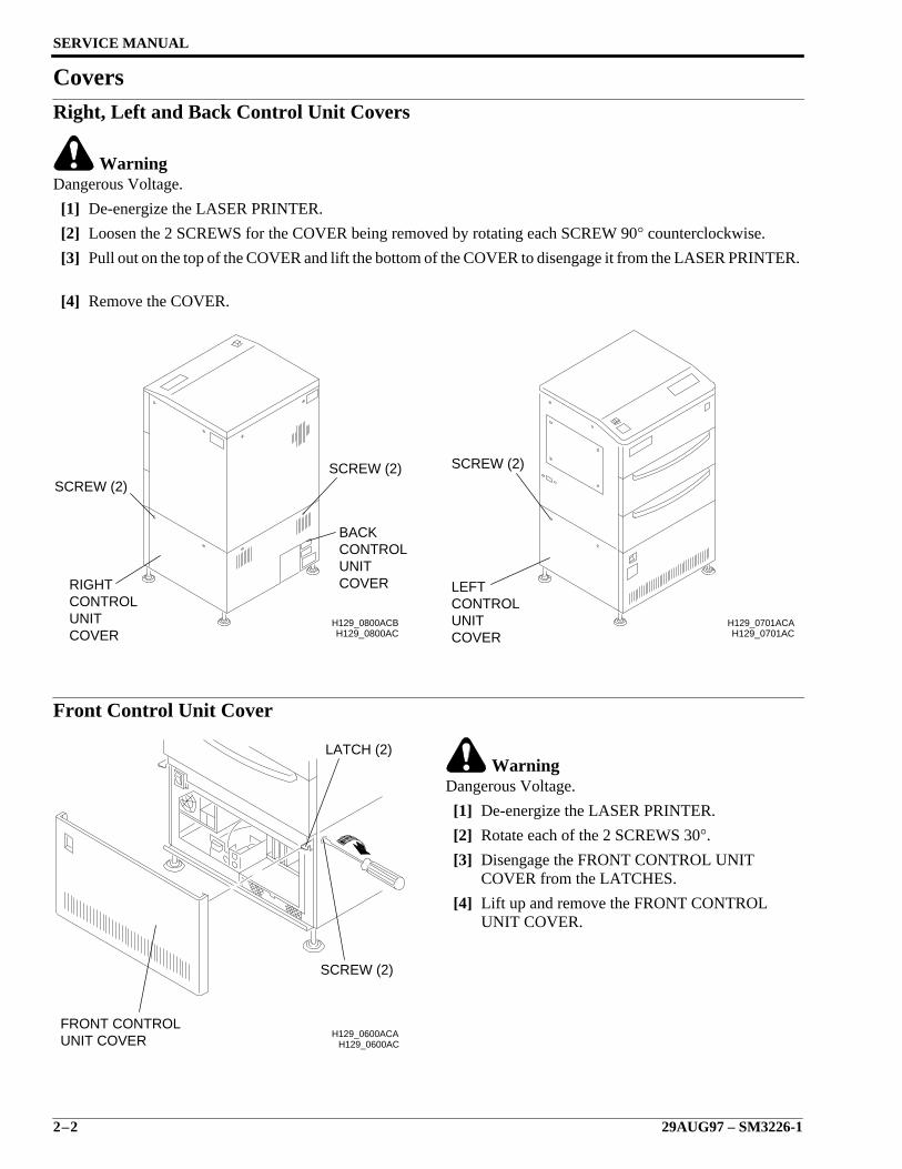
CoversRight, Left and Back Control Unit Covers
WarningDangerous Voltage.
[1] De-energize the LASER PRINTER.
[2] Loosen the 2 SCREWS for the COVER being removed by rotating each SCREW 90° counterclockwise.
[3] Pull out on the top of the COVER and lift the bottom of the COVER to disengage it from the LASER PRINTER.
[4] Remove the COVER.
Front Control Unit Cover
WarningDangerous Voltage.
[1] De-energize the LASER PRINTER.
[2] Rotate each of the 2 SCREWS 30°.
[3] Disengage the FRONT CONTROL UNITCOVER from the LATCHES.
[4] Lift up and remove the FRONT CONTROLUNIT COVER.
H129_0800AC
SCREW (2)
BACKCONTROLUNITCOVERRIGHT
CONTROLUNITCOVER
SCREW (2)
H129_0800ACBH129_0701AC
H129_0701ACA
COVERUNITCONTROLLEFT
SCREW (2)
H129_0600ACH129_0600ACA
UNIT COVERFRONT CONTROL
SCREW (2)
LATCH (2)
Removals
SM3226-1 – 29AUG97 2–3
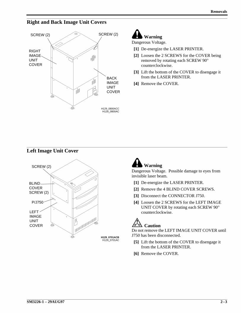
Right and Back Image Unit Covers
WarningDangerous Voltage.
[1] De-energize the LASER PRINTER.
[2] Loosen the 2 SCREWS for the COVER beingremoved by rotating each SCREW 90°counterclockwise.
[3] Lift the bottom of the COVER to disengage itfrom the LASER PRINTER.
[4] Remove the COVER.
Left Image Unit Cover
WarningDangerous Voltage. Possible damage to eyes frominvisible laser beam.
[1] De-energize the LASER PRINTER.
[2] Remove the 4 BLIND COVER SCREWS.
[3] Disconnect the CONNECTOR J750.
[4] Loosen the 2 SCREWS for the LEFT IMAGEUNIT COVER by rotating each SCREW 90°counterclockwise.
CautionDo not remove the LEFT IMAGE UNIT COVER untilJ750 has been disconnected.
[5] Lift the bottom of the COVER to disengage itfrom the LASER PRINTER.
[6] Remove the COVER.
H129_0800AC
COVERUNITIMAGEBACK
COVERUNITIMAGERIGHT
SCREW (2)SCREW (2)
H129_0800ACC
H129_0701ACH129_0701ACB
COVERUNITIMAGELEFT
P/J750
SCREW (2)COVERBLIND
SCREW (2)
SERVICE MANUAL
2–4 29AUG97 – SM3226-1
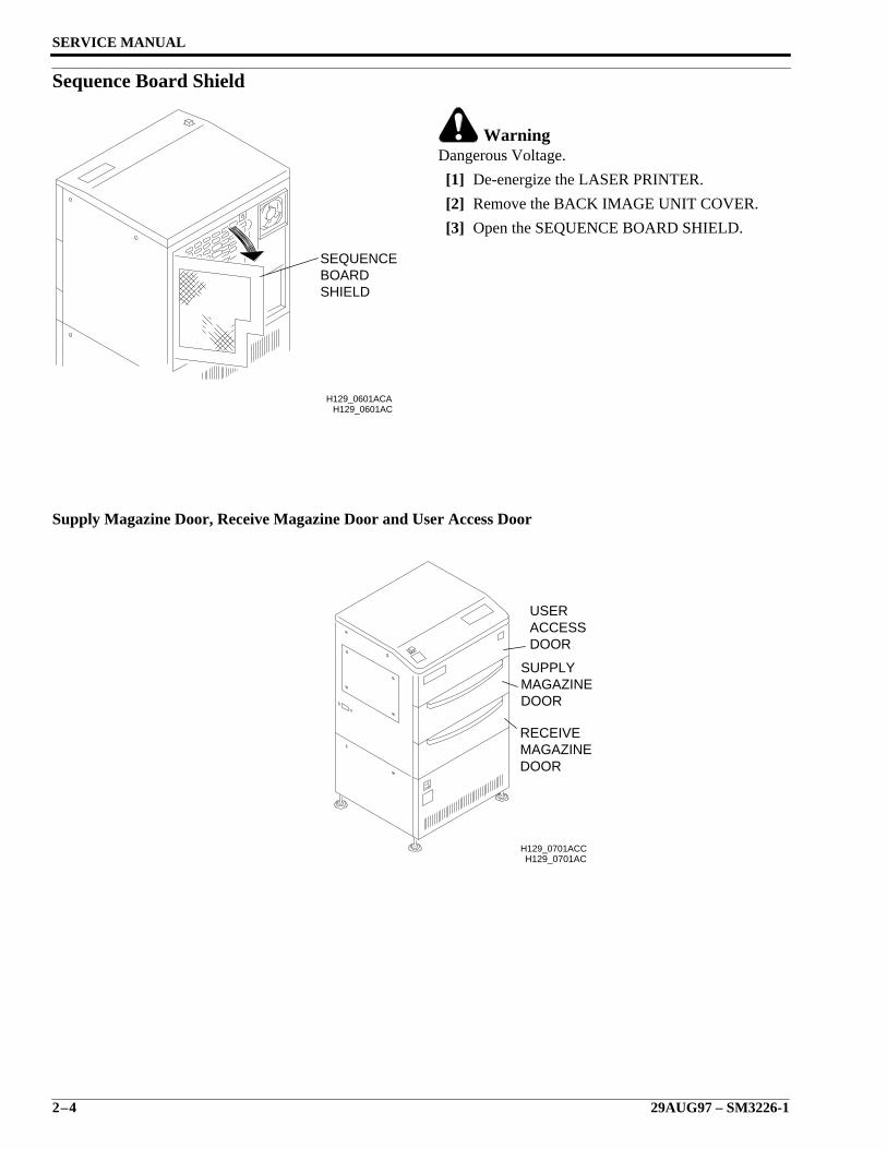
Sequence Board Shield
WarningDangerous Voltage.
[1] De-energize the LASER PRINTER.
[2] Remove the BACK IMAGE UNIT COVER.
[3] Open the SEQUENCE BOARD SHIELD.
Supply Magazine Door, Receive Magazine Door and User Access Door
H129_0601AC
SHIELDBOARDSEQUENCE
H129_0601ACA
H129_0701AC
DOORACCESSUSER
DOORMAGAZINERECEIVE
DOORMAGAZINESUPPLY
H129_0701ACC
Removals
SM3226-1 – 29AUG97 2–5
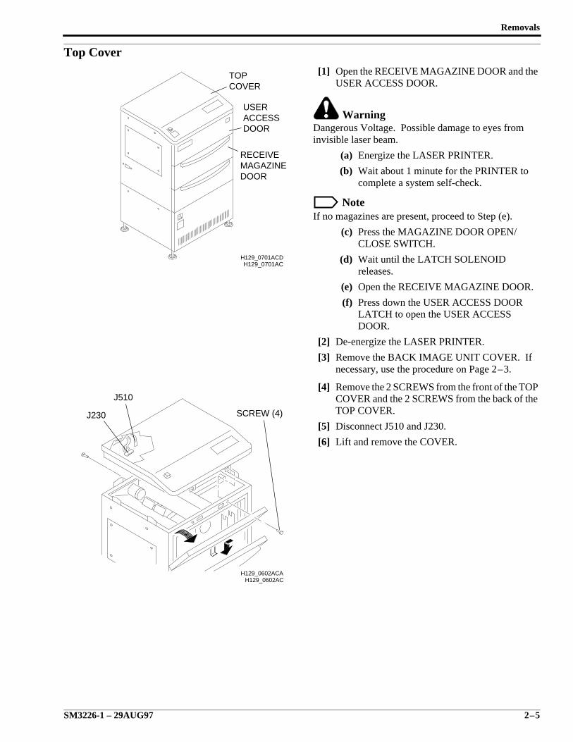
Top Cover[1] Open the RECEIVE MAGAZINE DOOR and the
USER ACCESS DOOR.
WarningDangerous Voltage. Possible damage to eyes frominvisible laser beam.
(a) Energize the LASER PRINTER.
(b) Wait about 1 minute for the PRINTER tocomplete a system self-check.
NoteIf no magazines are present, proceed to Step (e).
(c) Press the MAGAZINE DOOR OPEN/CLOSE SWITCH.
(d) Wait until the LATCH SOLENOIDreleases.
(e) Open the RECEIVE MAGAZINE DOOR.
(f) Press down the USER ACCESS DOORLATCH to open the USER ACCESSDOOR.
[2] De-energize the LASER PRINTER.
[3] Remove the BACK IMAGE UNIT COVER. Ifnecessary, use the procedure on Page 2–3.
[4] Remove the 2 SCREWS from the front of the TOPCOVER and the 2 SCREWS from the back of theTOP COVER.
[5] Disconnect J510 and J230.
[6] Lift and remove the COVER.
H129_0701AC
DOORACCESSUSER
COVERTOP
DOORMAGAZINERECEIVE
H129_0701ACD
H129_0602ACH129_0602ACA
J510
J230 SCREW (4)
SERVICE MANUAL
2–6 29AUG97 – SM3226-1
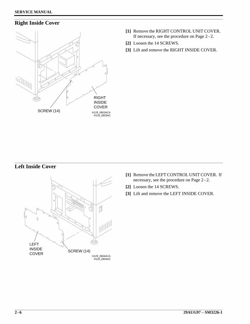
Right Inside Cover[1] Remove the RIGHT CONTROL UNIT COVER.
If necessary, see the procedure on Page 2–2.
[2] Loosen the 14 SCREWS.
[3] Lift and remove the RIGHT INSIDE COVER.
Left Inside Cover[1] Remove the LEFT CONTROL UNIT COVER. If
necessary, see the procedure on Page 2–2.
[2] Loosen the 14 SCREWS.
[3] Lift and remove the LEFT INSIDE COVER.
H129_0603ACH129_0603ACA
COVERINSIDERIGHT
SCREW (14)
H129_0604ACH129_0604ACA
SCREW (14)COVERINSIDELEFT
Removals
SM3226-1 – 29AUG97 2–7
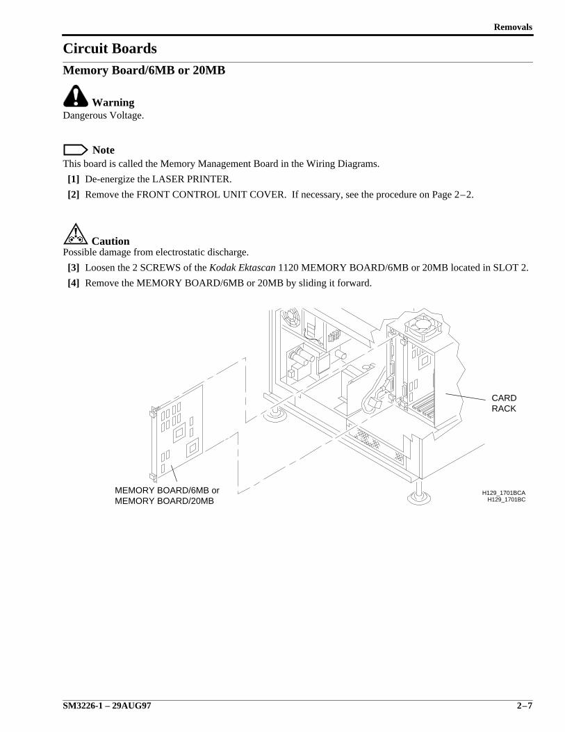
Circuit BoardsMemory Board/6MB or 20MB
WarningDangerous Voltage.
NoteThis board is called the Memory Management Board in the Wiring Diagrams.
[1] De-energize the LASER PRINTER.
[2] Remove the FRONT CONTROL UNIT COVER. If necessary, see the procedure on Page 2–2.
CautionPossible damage from electrostatic discharge.
[3] Loosen the 2 SCREWS of the Kodak Ektascan 1120 MEMORY BOARD/6MB or 20MB located in SLOT 2.
[4] Remove the MEMORY BOARD/6MB or 20MB by sliding it forward.
H129_1701BC
RACKCARD
MEMORY BOARD/20MBMEMORY BOARD/6MB or H129_1701BCA
SERVICE MANUAL
2–8 29AUG97 – SM3226-1
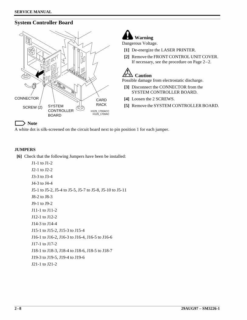
System Controller Board
WarningDangerous Voltage.
[1] De-energize the LASER PRINTER.
[2] Remove the FRONT CONTROL UNIT COVER.If necessary, see the procedure on Page 2–2.
CautionPossible damage from electrostatic discharge.
[3] Disconnect the CONNECTOR from theSYSTEM CONTROLLER BOARD.
[4] Loosen the 2 SCREWS.
[5] Remove the SYSTEM CONTROLLER BOARD.
NoteA white dot is silk-screened on the circuit board next to pin position 1 for each jumper.
JUMPERS
[6] Check that the following Jumpers have been be installed:
J1-1 to J1-2
J2-1 to J2-2
J3-3 to J3-4
J4-3 to J4-4
J5-1 to J5-2, J5-4 to J5-5, J5-7 to J5-8, J5-10 to J5-11
J8-2 to J8-3
J9-1 to J9-2
J11-1 to J11-2
J12-1 to J12-2
J14-3 to J14-4
J15-1 to J15-2, J15-3 to J15-4
J16-1 to J16-2, J16-3 to J16-4, J16-5 to J16-6
J17-1 to J17-2
J18-1 to J18-3, J18-4 to J18-6, J18-5 to J18-7
J19-3 to J19-5, J19-4 to J19-6
J21-1 to J21-2
H129_1700ACH129_1700ACC
CONNECTOR CARDRACK
SCREW (2) SYSTEMCONTROLLERBOARD
Removals
SM3226-1 – 29AUG97 2–9
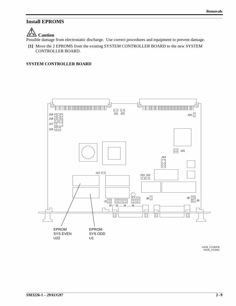
Install EPROMS
CautionPossible damage from electrostatic discharge. Use correct procedures and equipment to prevent damage.
[1] Move the 2 EPROMS from the existing SYSTEM CONTROLLER BOARD to the new SYSTEMCONTROLLER BOARD.
SYSTEM CONTROLLER BOARD
H129_1712DC
J1
J2 J3 J4 J5
J6 J8J9
J10 J11J12
J14
J15
J16
J17
J18
J19 J20J21 J22
H129_1712DCE
U1SYS ODDEPROM
U22SYS EVENEPROM
SERVICE MANUAL
2–10 29AUG97 – SM3226-1
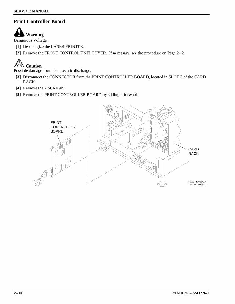
Print Controller Board
WarningDangerous Voltage.
[1] De-energize the LASER PRINTER.
[2] Remove the FRONT CONTROL UNIT COVER. If necessary, see the procedure on Page 2–2.
CautionPossible damage from electrostatic discharge.
[3] Disconnect the CONNECTOR from the PRINT CONTROLLER BOARD, located in SLOT 3 of the CARDRACK.
[4] Remove the 2 SCREWS.
[5] Remove the PRINT CONTROLLER BOARD by sliding it forward.
H129_1702BC
BOARDCONTROLLERPRINT
RACKCARD
H129_1702BCA
Removals
SM3226-1 – 29AUG97 2–11
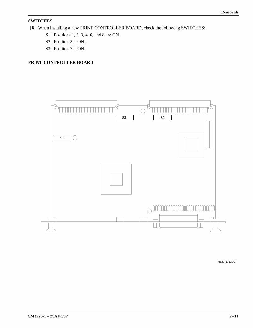
SWITCHES
[6] When installing a new PRINT CONTROLLER BOARD, check the following SWITCHES:
S1: Positions 1, 2, 3, 4, 6, and 8 are ON.
S2: Position 2 is ON.
S3: Position 7 is ON.
PRINT CONTROLLER BOARD
H129_1713DC
S3 S2
S1
SERVICE MANUAL
2–12 29AUG97 – SM3226-1
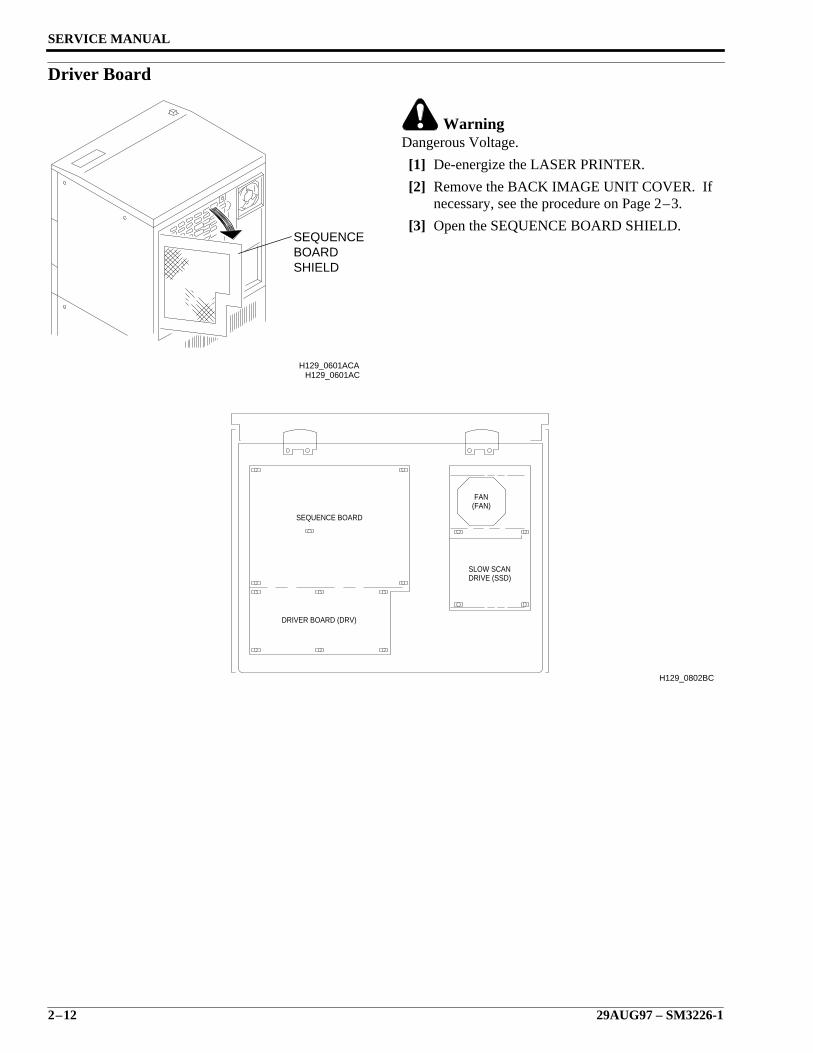
Driver Board
WarningDangerous Voltage.
[1] De-energize the LASER PRINTER.
[2] Remove the BACK IMAGE UNIT COVER. Ifnecessary, see the procedure on Page 2–3.
[3] Open the SEQUENCE BOARD SHIELD.
H129_0601AC
SHIELDBOARDSEQUENCE
H129_0601ACA
H129_0802BC
SEQUENCE BOARD
SLOW SCANDRIVE (SSD)
FAN(FAN)
DRIVER BOARD (DRV)
Removals
SM3226-1 – 29AUG97 2–13
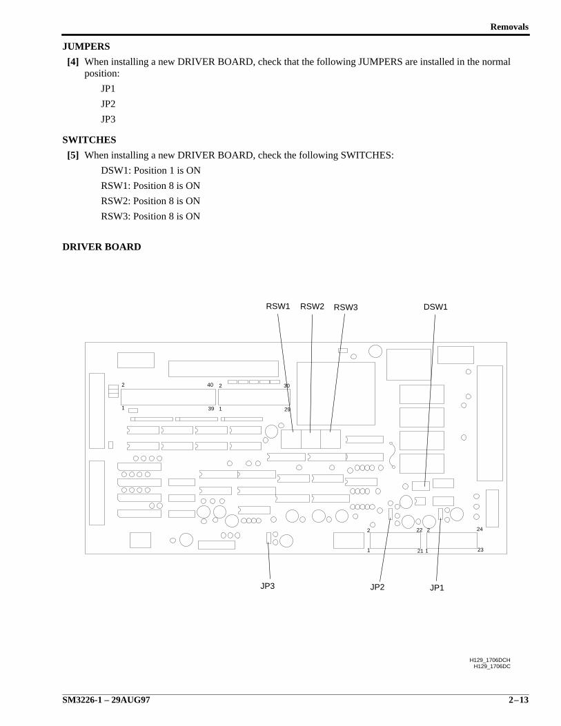
JUMPERS
[4] When installing a new DRIVER BOARD, check that the following JUMPERS are installed in the normalposition:
JP1
JP2
JP3
SWITCHES
[5] When installing a new DRIVER BOARD, check the following SWITCHES:
DSW1: Position 1 is ON
RSW1: Position 8 is ON
RSW2: Position 8 is ON
RSW3: Position 8 is ON
DRIVER BOARD
29
30
39
40
1
2
1
2
H129_1706DC
1
2 22
21 1
2
23
24
H129_1706DCH
JP3 JP2 JP1
DSW1RSW3RSW2RSW1
SERVICE MANUAL
2–14 29AUG97 – SM3226-1
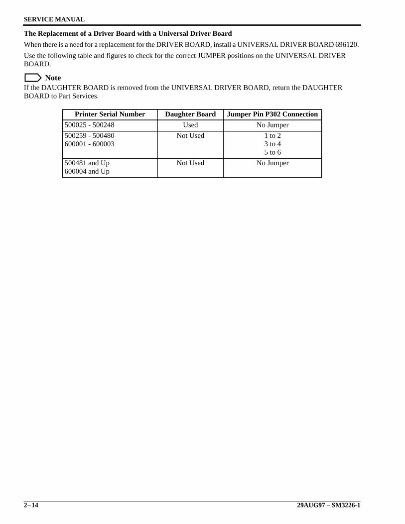
The Replacement of a Driver Board with a Universal Driver Board
When there is a need for a replacement for the DRIVER BOARD, install a UNIVERSAL DRIVER BOARD 696120.
Use the following table and figures to check for the correct JUMPER positions on the UNIVERSAL DRIVERBOARD.
NoteIf the DAUGHTER BOARD is removed from the UNIVERSAL DRIVER BOARD, return the DAUGHTERBOARD to Part Services.
Printer Serial Number Daughter Board Jumper Pin P302 Connection
500025 - 500248 Used No Jumper
500259 - 500480600001 - 600003
Not Used 1 to 23 to 45 to 6
500481 and Up600004 and Up
Not Used No Jumper
Removals
SM3226-1 – 29AUG97 2–15
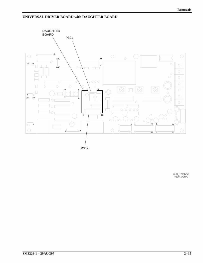
UNIVERSAL DRIVER BOARD with DAUGHTER BOARD
H129_1726DC
33
1
2 22
21
24
23
1
2
11
12
2
1101
101
1 5
12
2
1
30 29
2 1
34
18
17A40
B40
A1
B1
10
15
6
P302
DAUGHTERBOARD
P301
H129_1726DCC
SERVICE MANUAL
2–16 29AUG97 – SM3226-1
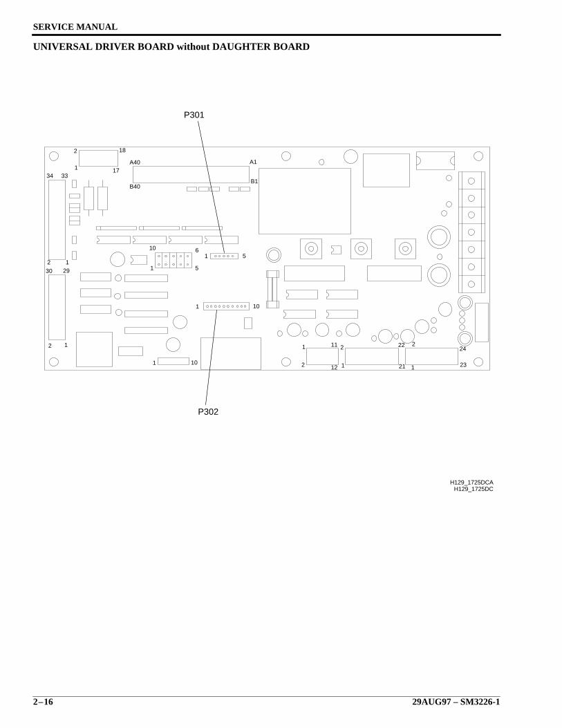
UNIVERSAL DRIVER BOARD without DAUGHTER BOARD
1
2 22
21
24
23
1
2
11
12
2
1101
101
1 5
12
2
1
30 292 1
34
18
17A40
B40
A1
B1
10
1 5
6
33
H129_1725DC
P302
P301
H129_1725DCA
Removals
SM3226-1 – 29AUG97 2–17
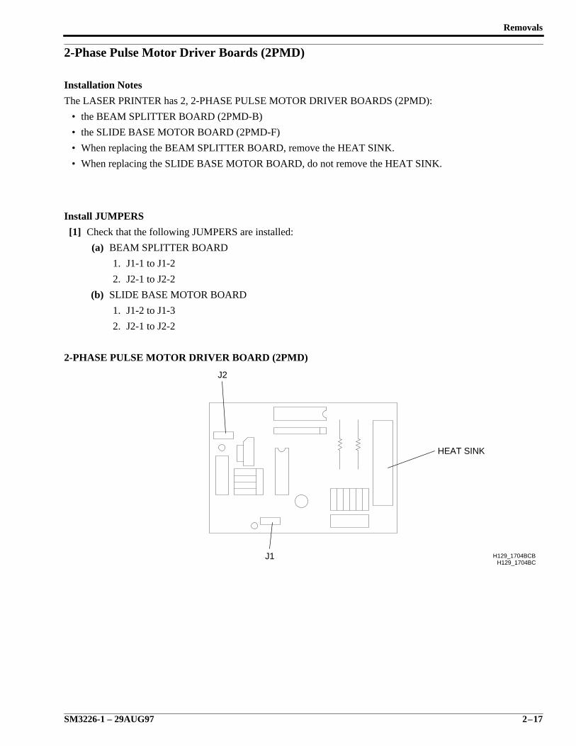
2-Phase Pulse Motor Driver Boards (2PMD)
Installation Notes
The LASER PRINTER has 2, 2-PHASE PULSE MOTOR DRIVER BOARDS (2PMD):
• the BEAM SPLITTER BOARD (2PMD-B)
• the SLIDE BASE MOTOR BOARD (2PMD-F)
• When replacing the BEAM SPLITTER BOARD, remove the HEAT SINK.
• When replacing the SLIDE BASE MOTOR BOARD, do not remove the HEAT SINK.
Install JUMPERS
[1] Check that the following JUMPERS are installed:
(a) BEAM SPLITTER BOARD
1. J1-1 to J1-2
2. J2-1 to J2-2
(b) SLIDE BASE MOTOR BOARD
1. J1-2 to J1-3
2. J2-1 to J2-2
2-PHASE PULSE MOTOR DRIVER BOARD (2PMD)
H129_1704BC
J2
J1
HEAT SINK
H129_1704BCB
SERVICE MANUAL
2–18 29AUG97 – SM3226-1
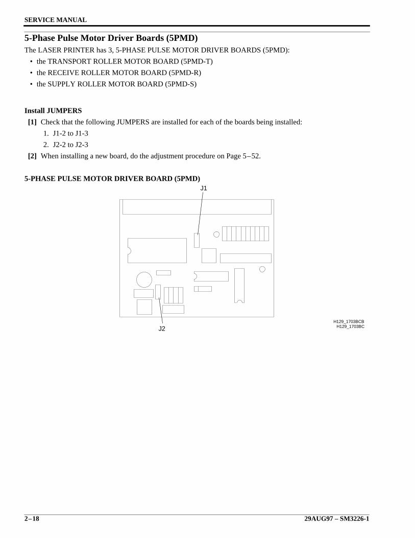
5-Phase Pulse Motor Driver Boards (5PMD)The LASER PRINTER has 3, 5-PHASE PULSE MOTOR DRIVER BOARDS (5PMD):
• the TRANSPORT ROLLER MOTOR BOARD (5PMD-T)
• the RECEIVE ROLLER MOTOR BOARD (5PMD-R)
• the SUPPLY ROLLER MOTOR BOARD (5PMD-S)
Install JUMPERS
[1] Check that the following JUMPERS are installed for each of the boards being installed:
1. J1-2 to J1-3
2. J2-2 to J2-3
[2] When installing a new board, do the adjustment procedure on Page 5–52.
5-PHASE PULSE MOTOR DRIVER BOARD (5PMD)
H129_1703BCH129_1703BCB
J2
J1
Removals
SM3226-1 – 29AUG97 2–19
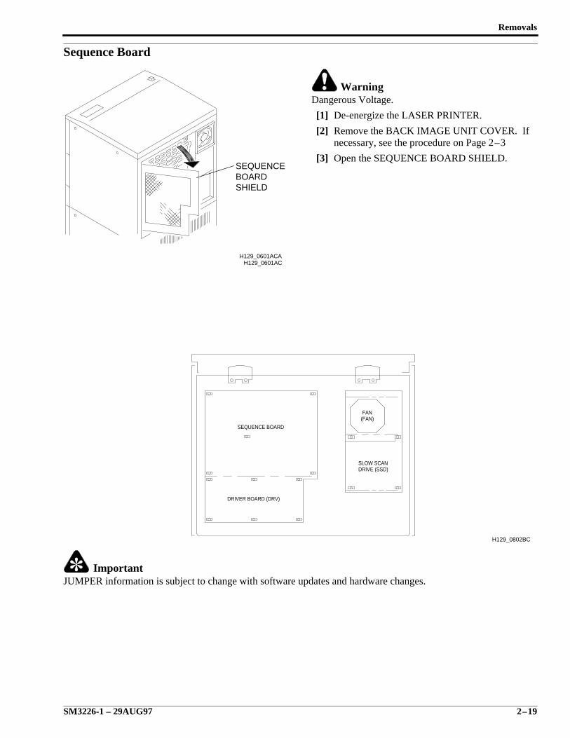
Sequence Board
WarningDangerous Voltage.
[1] De-energize the LASER PRINTER.
[2] Remove the BACK IMAGE UNIT COVER. Ifnecessary, see the procedure on Page 2–3
[3] Open the SEQUENCE BOARD SHIELD.
ImportantJUMPER information is subject to change with software updates and hardware changes.
H129_0601AC
SHIELDBOARDSEQUENCE
H129_0601ACA
H129_0802BC
SEQUENCE BOARD
SLOW SCANDRIVE (SSD)
FAN(FAN)
DRIVER BOARD (DRV)
SERVICE MANUAL
2–20 29AUG97 – SM3226-1
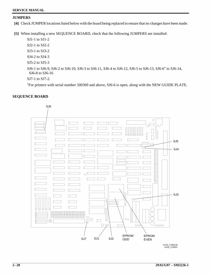
JUMPERS
[4] Check JUMPER locations listed below with the board being replaced to ensure that no changes have been made.
[5] When installing a new SEQUENCE BOARD, check that the following JUMPERS are installed:
SJ1-1 to SJ1-2
SJ2-1 to SJ2-2
SJ3-1 to SJ3-2
SJ4-2 to SJ4-3
SJ5-2 to SJ5-3
SJ6-1 to SJ6-9, SJ6-2 to SJ6-10, SJ6-3 to SJ6-11, SJ6-4 to SJ6-12, SJ6-5 to SJ6-13, SJ6-6* to SJ6-14, SJ6-8 to SJ6-16
SJ7-1 to SJ7-2.*For printers with serial number 500369 and above, SJ6-6 is open, along with the NEW GUIDE PLATE.
SEQUENCE BOARD
H129_1705DC
SJ1 SJ2
SJ3
SJ4
SJ5
SJ6
SJ7EPROMODD
EPROMEVEN
H129_1705DCB

Removals
SM3226-1 – 29AUG97 2–21
Install EPROMS
CautionPossible damage from electrostatic discharge. Use correct procedures and equipment to prevent damage.
[6] Move the 2 EPROMS from the existing SEQUENCE BOARD to the replacement SEQUENCE BOARD.
ImportantWhen installing a new SEQUENCE BOARD, do the setup procedure on Page 4–22.
SERVICE MANUAL
2–22 29AUG97 – SM3226-1
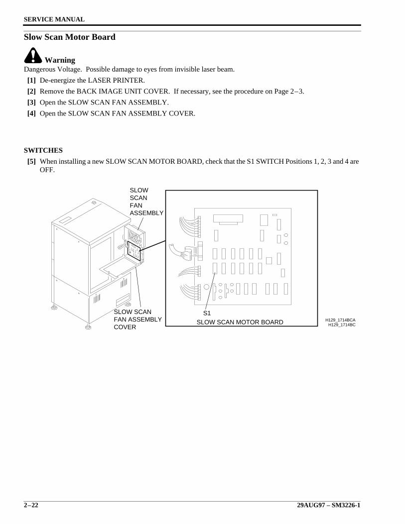
Slow Scan Motor Board
WarningDangerous Voltage. Possible damage to eyes from invisible laser beam.
[1] De-energize the LASER PRINTER.
[2] Remove the BACK IMAGE UNIT COVER. If necessary, see the procedure on Page 2–3.
[3] Open the SLOW SCAN FAN ASSEMBLY.
[4] Open the SLOW SCAN FAN ASSEMBLY COVER.
SWITCHES
[5] When installing a new SLOW SCAN MOTOR BOARD, check that the S1 SWITCH Positions 1, 2, 3 and 4 areOFF.
H129_1714BC
S1SLOW SCAN MOTOR BOARD
COVERFAN ASSEMBLYSLOW SCAN
ASSEMBLYFANSCANSLOW
H129_1714BCA
Removals
SM3226-1 – 29AUG97 2–23
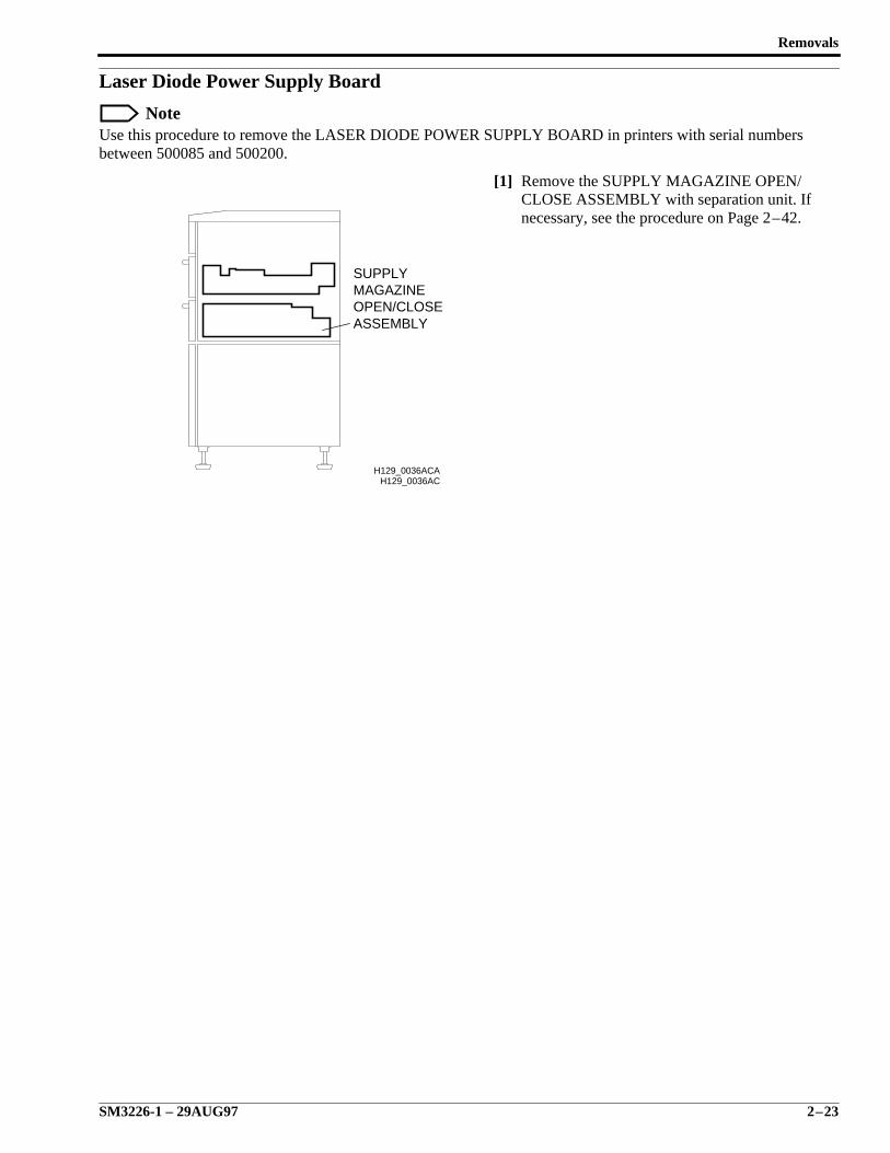
Laser Diode Power Supply Board
NoteUse this procedure to remove the LASER DIODE POWER SUPPLY BOARD in printers with serial numbersbetween 500085 and 500200.
[1] Remove the SUPPLY MAGAZINE OPEN/CLOSE ASSEMBLY with separation unit. Ifnecessary, see the procedure on Page 2–42.
H129_0036ACH129_0036ACA
ASSEMBLYOPEN/CLOSEMAGAZINESUPPLY
SERVICE MANUAL
2–24 29AUG97 – SM3226-1
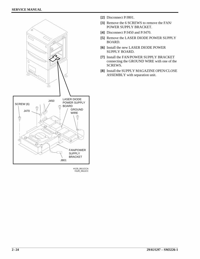
[2] Disconnect P/J801.
[3] Remove the 6 SCREWS to remove the FAN/POWER SUPPLY BRACKET.
[4] Disconnect P/J450 and P/J470.
[5] Remove the LASER DIODE POWER SUPPLYBOARD.
[6] Install the new LASER DIODE POWERSUPPLY BOARD.
[7] Install the FAN/POWER SUPPLY BRACKETconnecting the GROUND WIRE with one of theSCREWS.
[8] Install the SUPPLY MAGAZINE OPEN/CLOSEASSEMBLY with separation unit.
H129_0611CCH129_0611CCA
J801BRACKETSUPPLYFAN/POWER
WIREGROUND
BOARDPOWER SUPPLYLASER DIODE
J470
SCREW (6)J450
Removals
SM3226-1 – 29AUG97 2–25
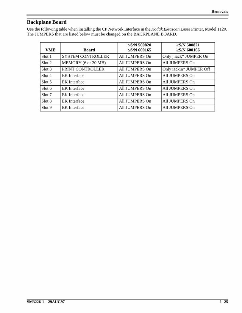
Backplane BoardUse the following table when installing the CP Network Interface in the Kodak Ektascan Laser Printer, Model 1120.The JUMPERS that are listed below must be changed on the BACKPLANE BOARD.
VME Board≤S/N 500820≤S/N 600165
≥S/N 500821≥S/N 600166
Slot 1 SYSTEM CONTROLLER All JUMPERS On Only j.iack* JUMPER On
Slot 2 MEMORY (6 or 20 MB) All JUMPERS On All JUMPERS On
Slot 3 PRINT CONTROLLER All JUMPERS On Only iackin* JUMPER Off
Slot 4 EK Interface All JUMPERS On All JUMPERS On
Slot 5 EK Interface All JUMPERS On All JUMPERS On
Slot 6 EK Interface All JUMPERS On All JUMPERS On
Slot 7 EK Interface All JUMPERS On All JUMPERS On
Slot 8 EK Interface All JUMPERS On All JUMPERS On
Slot 9 EK Interface All JUMPERS On All JUMPERS On
SERVICE MANUAL
2–26 29AUG97 – SM3226-1
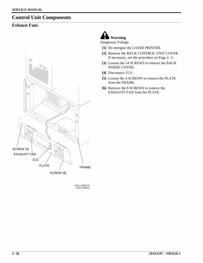
Control Unit ComponentsExhaust Fans
WarningDangerous Voltage.
[1] De-energize the LASER PRINTER.
[2] Remove the BACK CONTROL UNIT COVER.If necessary, see the procedure on Page 2–2.
[3] Loosen the 14 SCREWS to remove the BACKINSIDE COVER.
[4] Disconnect J121.
[5] Loosen the 4 SCREWS to remove the PLATEfrom the FRAME.
[6] Remove the 8 SCREWS to remove theEXHAUST FAN from the PLATE.
H129_1905CC
SCREW (4)
EXHAUST FAN
J121
PLATE
SCREW (8)
FRAME
H129_1905CCA
Removals
SM3226-1 – 29AUG97 2–27
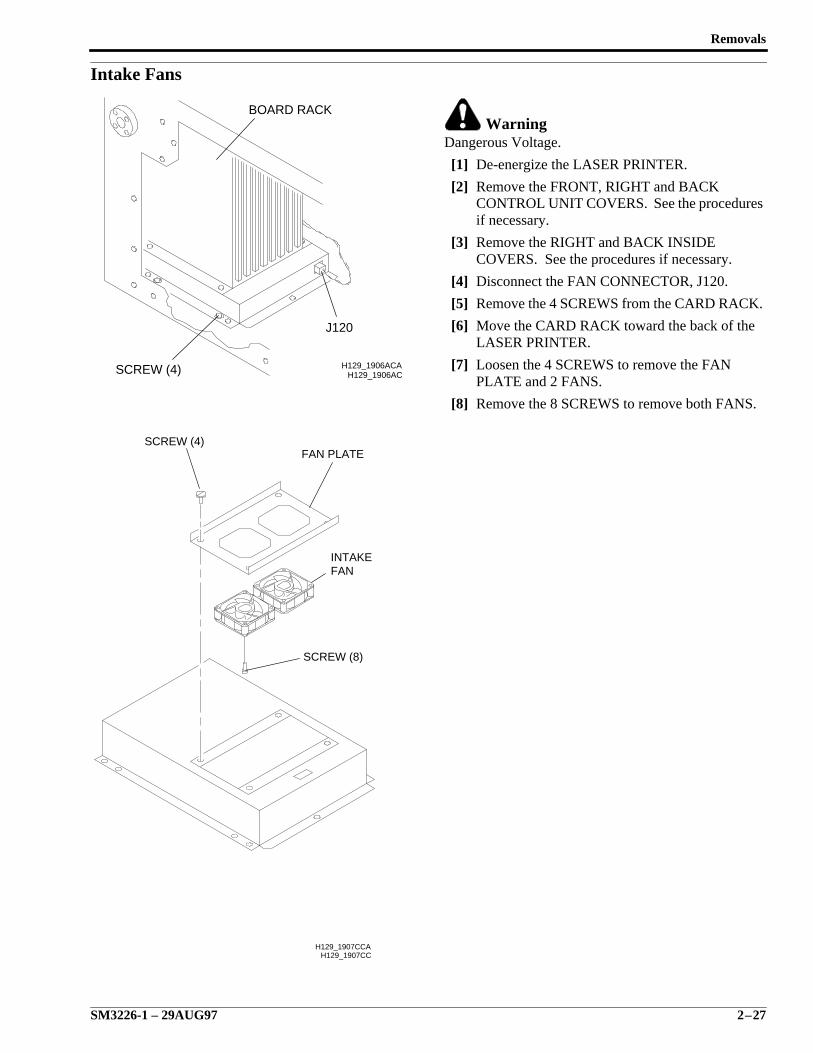
Intake Fans
WarningDangerous Voltage.
[1] De-energize the LASER PRINTER.
[2] Remove the FRONT, RIGHT and BACKCONTROL UNIT COVERS. See the proceduresif necessary.
[3] Remove the RIGHT and BACK INSIDECOVERS. See the procedures if necessary.
[4] Disconnect the FAN CONNECTOR, J120.
[5] Remove the 4 SCREWS from the CARD RACK.
[6] Move the CARD RACK toward the back of theLASER PRINTER.
[7] Loosen the 4 SCREWS to remove the FANPLATE and 2 FANS.
[8] Remove the 8 SCREWS to remove both FANS.
H129_1906ACH129_1906ACASCREW (4)
J120
BOARD RACK
H129_1907CC
FANINTAKE
SCREW (8)
FAN PLATESCREW (4)
H129_1907CCA
SERVICE MANUAL
2–28 29AUG97 – SM3226-1
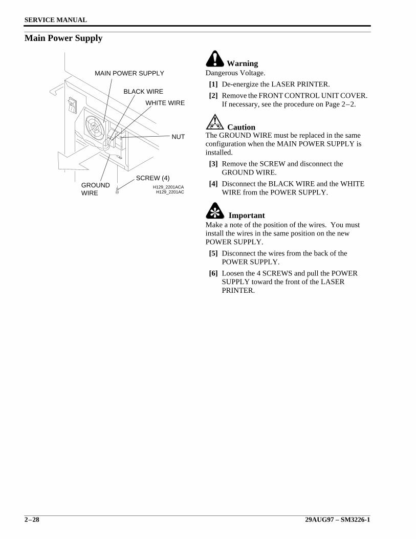
Main Power Supply
WarningDangerous Voltage.
[1] De-energize the LASER PRINTER.
[2] Remove the FRONT CONTROL UNIT COVER.If necessary, see the procedure on Page 2–2.
CautionThe GROUND WIRE must be replaced in the sameconfiguration when the MAIN POWER SUPPLY isinstalled.
[3] Remove the SCREW and disconnect theGROUND WIRE.
[4] Disconnect the BLACK WIRE and the WHITEWIRE from the POWER SUPPLY.
ImportantMake a note of the position of the wires. You mustinstall the wires in the same position on the newPOWER SUPPLY.
[5] Disconnect the wires from the back of thePOWER SUPPLY.
[6] Loosen the 4 SCREWS and pull the POWERSUPPLY toward the front of the LASERPRINTER.
H129_2201ACH129_2201ACA
WIREGROUND
SCREW (4)
NUT
WHITE WIRE
BLACK WIRE
MAIN POWER SUPPLY
Removals
SM3226-1 – 29AUG97 2–29
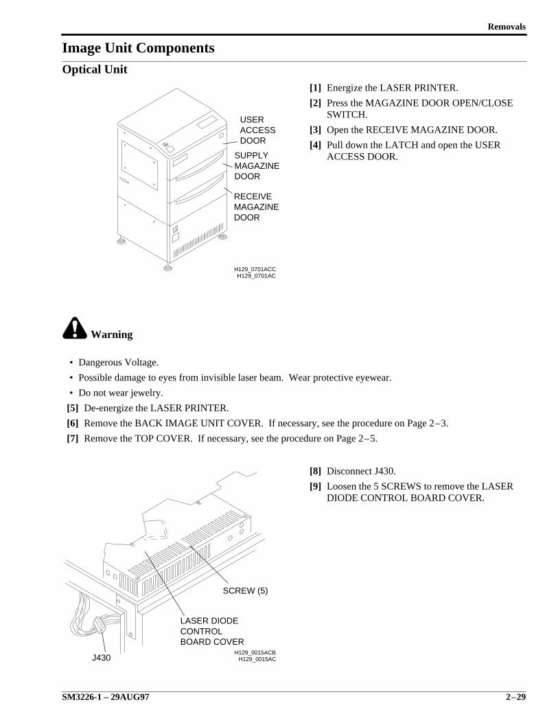
Image Unit ComponentsOptical Unit
[1] Energize the LASER PRINTER.
[2] Press the MAGAZINE DOOR OPEN/CLOSESWITCH.
[3] Open the RECEIVE MAGAZINE DOOR.
[4] Pull down the LATCH and open the USERACCESS DOOR.
Warning
• Dangerous Voltage.
• Possible damage to eyes from invisible laser beam. Wear protective eyewear.
• Do not wear jewelry.
[5] De-energize the LASER PRINTER.
[6] Remove the BACK IMAGE UNIT COVER. If necessary, see the procedure on Page 2–3.
[7] Remove the TOP COVER. If necessary, see the procedure on Page 2–5.
[8] Disconnect J430.
[9] Loosen the 5 SCREWS to remove the LASERDIODE CONTROL BOARD COVER.
H129_0701AC
DOORACCESSUSER
DOORMAGAZINERECEIVE
DOORMAGAZINESUPPLY
H129_0701ACC
H129_0015AC
BOARD COVERCONTROLLASER DIODE
J430
SCREW (5)
H129_0015ACB
SERVICE MANUAL
2–30 29AUG97 – SM3226-1
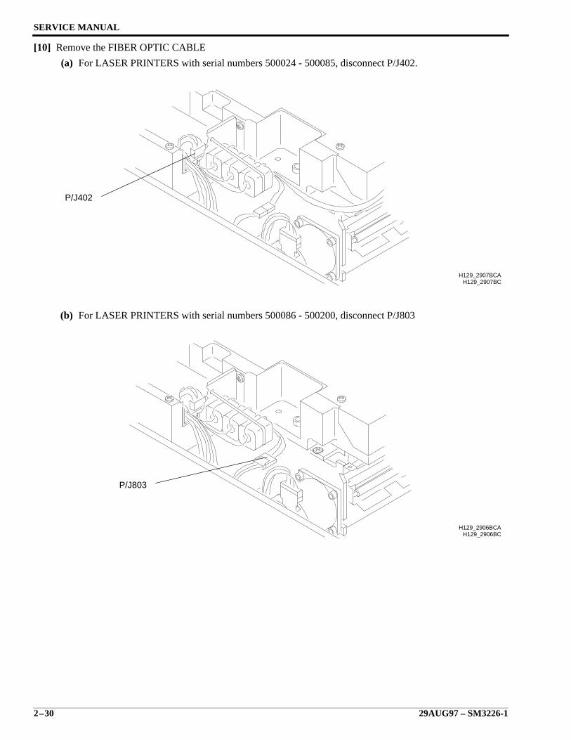
[10] Remove the FIBER OPTIC CABLE
(a) For LASER PRINTERS with serial numbers 500024 - 500085, disconnect P/J402.
(b) For LASER PRINTERS with serial numbers 500086 - 500200, disconnect P/J803
H129_2907BCH129_2907BCA
P/J402
H129_2906BCH129_2906BCA
P/J803
Removals
SM3226-1 – 29AUG97 2–31
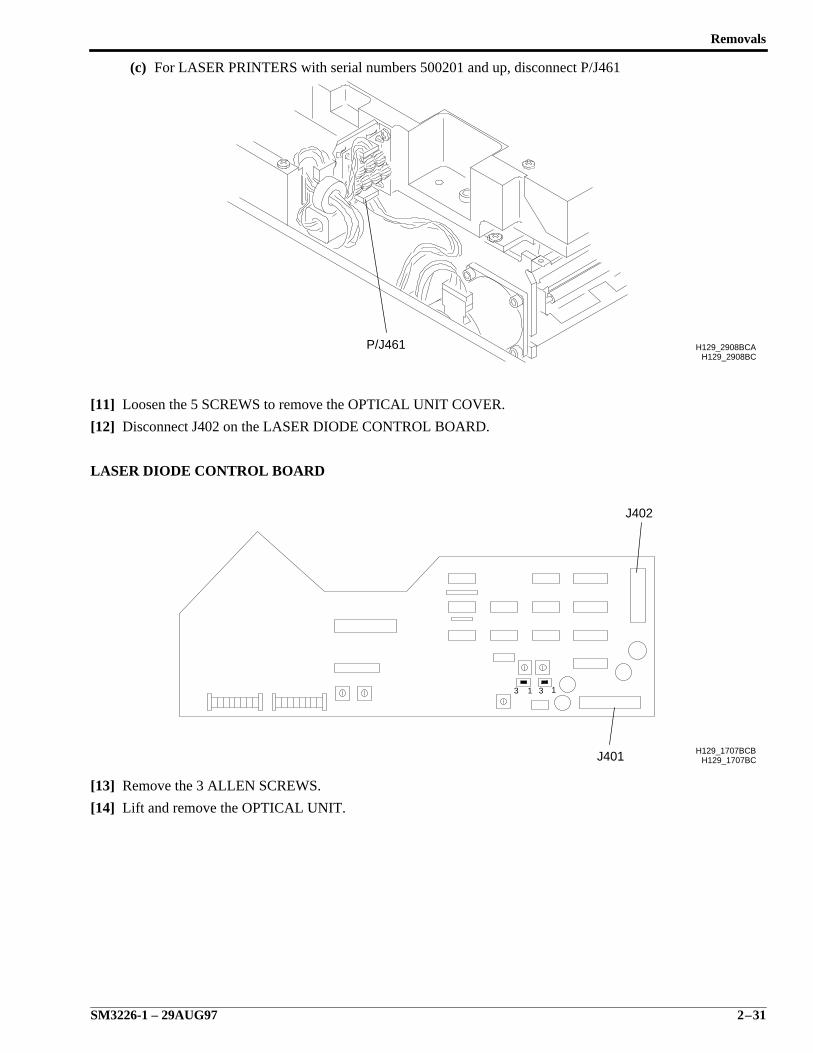
(c) For LASER PRINTERS with serial numbers 500201 and up, disconnect P/J461
[11] Loosen the 5 SCREWS to remove the OPTICAL UNIT COVER.
[12] Disconnect J402 on the LASER DIODE CONTROL BOARD.
LASER DIODE CONTROL BOARD
[13] Remove the 3 ALLEN SCREWS.
[14] Lift and remove the OPTICAL UNIT.
H129_2908BCH129_2908BCAP/J461
H129_1707BC
3 1 3 1
H129_1707BCB
J402
J401
SERVICE MANUAL
2–32 29AUG97 – SM3226-1
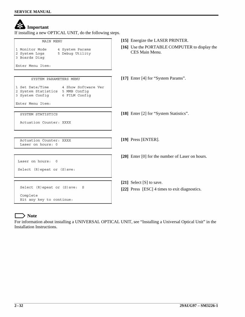
ImportantIf installing a new OPTICAL UNIT, do the following steps.
[15] Energize the LASER PRINTER.
[16] Use the PORTABLE COMPUTER to display theCES Main Menu.
[17] Enter [4] for “System Params”.
[18] Enter [2] for “System Statistics”.
[19] Press [ENTER].
[20] Enter [0] for the number of Laser on hours.
[21] Select [S] to save.
[22] Press [ESC] 4 times to exit diagnostics.
NoteFor information about installing a UNIVERSAL OPTICAL UNIT, see “Installing a Universal Optical Unit” in theInstallation Instructions.
MAIN MENU
1 Monitor Mode 4 System Params2 System Logs 5 Debug Utility3 Boards Diag
Enter Menu Item:
SYSTEM PARAMETERS MENU
1 Set Date/Time 4 Show Software Ver2 System Statistics 5 MMB Config3 System Config 6 FILM Config
Enter Menu Item:
SYSTEM STATISTICS
Actuation Counter: XXXX
Actuation Counter: XXXX Laser on hours: 0
Laser on hours: 0
Select (R)epeat or (S)ave:
Select (R)epeat or (S)ave: S
Complete Hit any key to continue:
Removals
SM3226-1 – 29AUG97 2–33
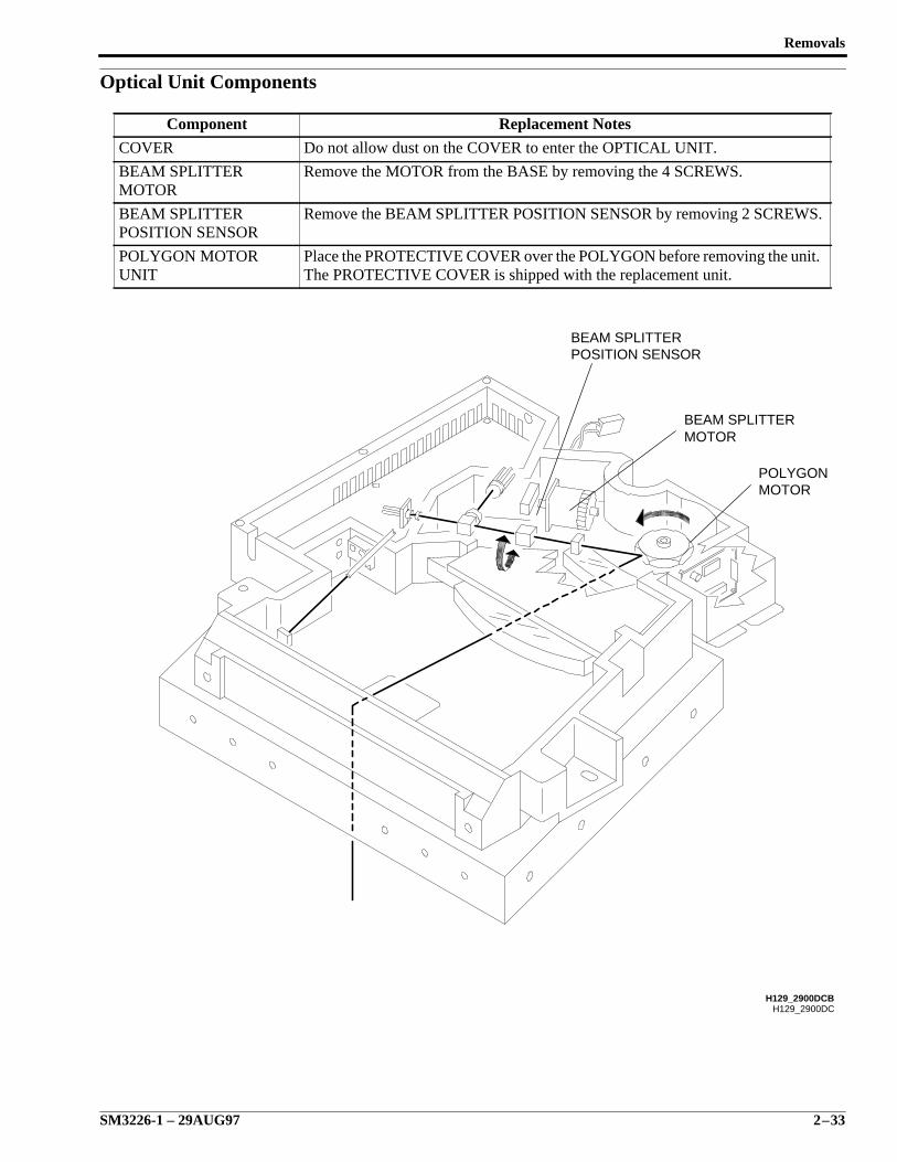
Optical Unit Components
Component Replacement Notes
COVER Do not allow dust on the COVER to enter the OPTICAL UNIT.
BEAM SPLITTERMOTOR
Remove the MOTOR from the BASE by removing the 4 SCREWS.
BEAM SPLITTERPOSITION SENSOR
Remove the BEAM SPLITTER POSITION SENSOR by removing 2 SCREWS.
POLYGON MOTORUNIT
Place the PROTECTIVE COVER over the POLYGON before removing the unit.The PROTECTIVE COVER is shipped with the replacement unit.
H129_2900DC
MOTORPOLYGON
MOTORBEAM SPLITTER
H129_2900DCB
POSITION SENSORBEAM SPLITTER
SERVICE MANUAL
2–34 29AUG97 – SM3226-1
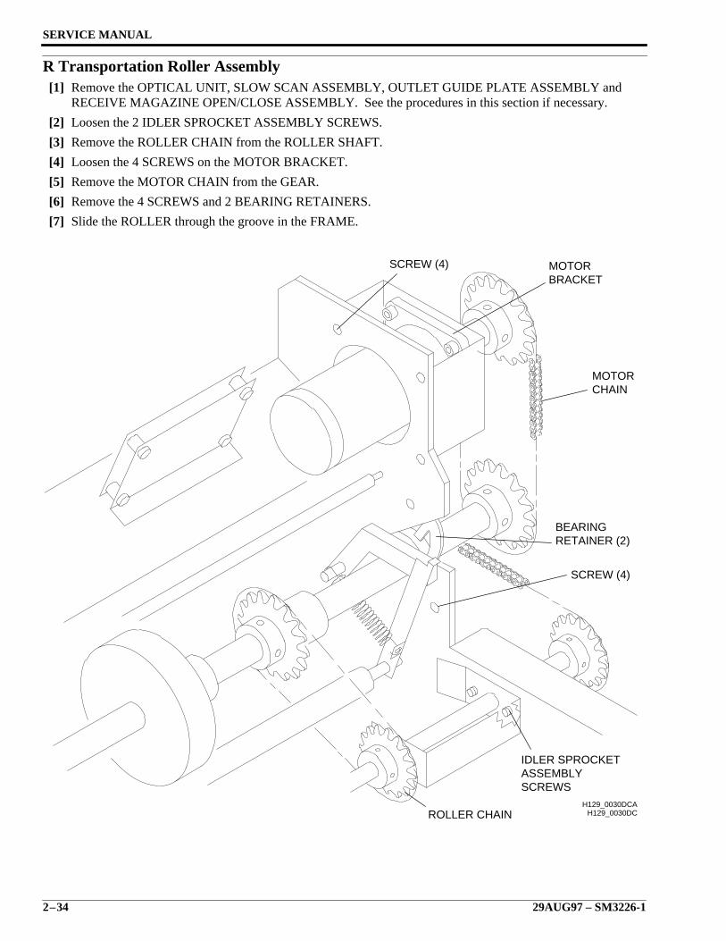
R Transportation Roller Assembly[1] Remove the OPTICAL UNIT, SLOW SCAN ASSEMBLY, OUTLET GUIDE PLATE ASSEMBLY and
RECEIVE MAGAZINE OPEN/CLOSE ASSEMBLY. See the procedures in this section if necessary.
[2] Loosen the 2 IDLER SPROCKET ASSEMBLY SCREWS.
[3] Remove the ROLLER CHAIN from the ROLLER SHAFT.
[4] Loosen the 4 SCREWS on the MOTOR BRACKET.
[5] Remove the MOTOR CHAIN from the GEAR.
[6] Remove the 4 SCREWS and 2 BEARING RETAINERS.
[7] Slide the ROLLER through the groove in the FRAME.
H129_0030DC
RETAINER (2)BEARING
SCREW (4) MOTORBRACKET
MOTORCHAIN
SCREW (4)
ROLLER CHAIN
IDLER SPROCKETASSEMBLYSCREWS
H129_0030DCA
Removals
SM3226-1 – 29AUG97 2–35
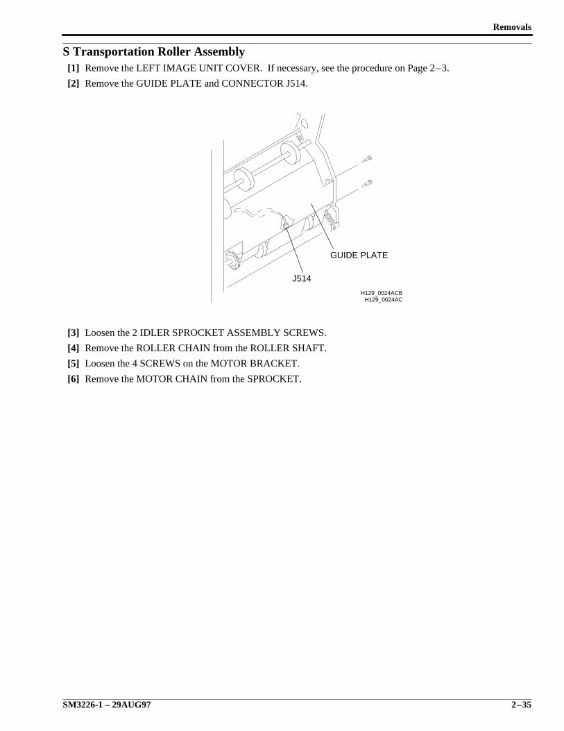
S Transportation Roller Assembly[1] Remove the LEFT IMAGE UNIT COVER. If necessary, see the procedure on Page 2–3.
[2] Remove the GUIDE PLATE and CONNECTOR J514.
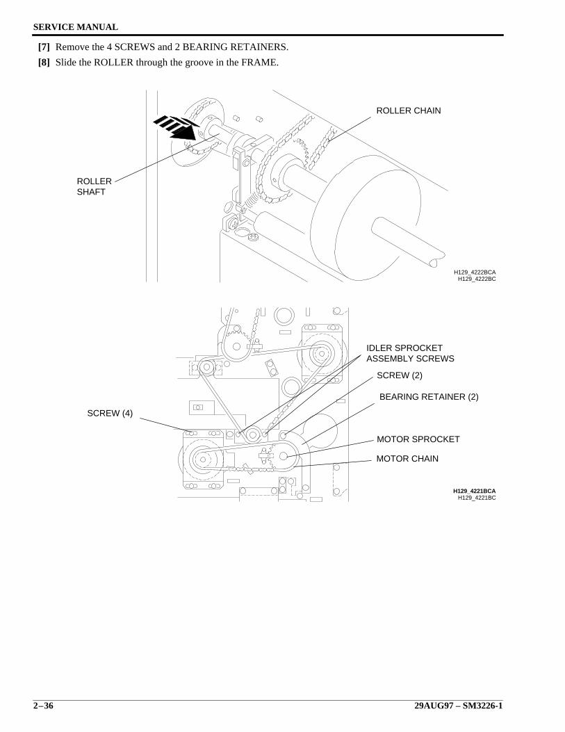
[3] Loosen the 2 IDLER SPROCKET ASSEMBLY SCREWS.
[4] Remove the ROLLER CHAIN from the ROLLER SHAFT.
[5] Loosen the 4 SCREWS on the MOTOR BRACKET.
[6] Remove the MOTOR CHAIN from the SPROCKET.
H129_0024ACH129_0024ACB
J514
GUIDE PLATE
SERVICE MANUAL
2–36 29AUG97 – SM3226-1
[7] Remove the 4 SCREWS and 2 BEARING RETAINERS.
[8] Slide the ROLLER through the groove in the FRAME.
H129_4222BCH129_4222BCA
SHAFTROLLER
ROLLER CHAIN
H129_4221BCH129_4221BCA
SCREW (4)
IDLER SPROCKETASSEMBLY SCREWS
SCREW (2)
BEARING RETAINER (2)
MOTOR SPROCKET
MOTOR CHAIN
Removals
SM3226-1 – 29AUG97 2–37
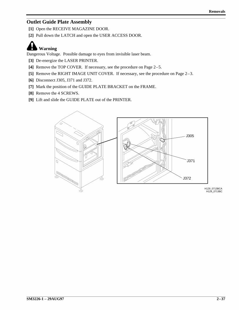
Outlet Guide Plate Assembly[1] Open the RECEIVE MAGAZINE DOOR.
[2] Pull down the LATCH and open the USER ACCESS DOOR.
WarningDangerous Voltage. Possible damage to eyes from invisible laser beam.
[3] De-energize the LASER PRINTER.
[4] Remove the TOP COVER. If necessary, see the procedure on Page 2–5.
[5] Remove the RIGHT IMAGE UNIT COVER. If necessary, see the procedure on Page 2–3.
[6] Disconnect J305, J371 and J372.
[7] Mark the position of the GUIDE PLATE BRACKET on the FRAME.
[8] Remove the 4 SCREWS.
[9] Lift and slide the GUIDE PLATE out of the PRINTER.
H129_0713BCH129_0713BCA
J372
J371
J305
SERVICE MANUAL
2–38 29AUG97 – SM3226-1
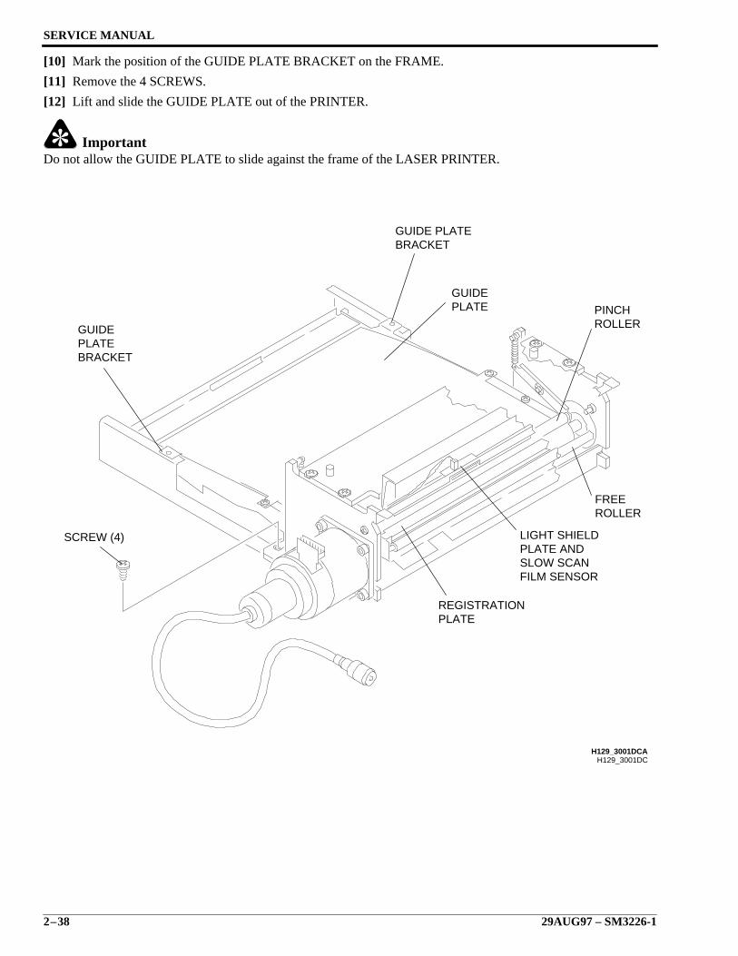
[10] Mark the position of the GUIDE PLATE BRACKET on the FRAME.
[11] Remove the 4 SCREWS.
[12] Lift and slide the GUIDE PLATE out of the PRINTER.
ImportantDo not allow the GUIDE PLATE to slide against the frame of the LASER PRINTER.
H129_3001DC
BRACKETPLATEGUIDE
BRACKETGUIDE PLATE
H129_3001DCA
GUIDEPLATE PINCH
ROLLER
FREEROLLER
LIGHT SHIELDPLATE ANDSLOW SCANFILM SENSOR
REGISTRATIONPLATE
SCREW (4)
Removals
SM3226-1 – 29AUG97 2–39
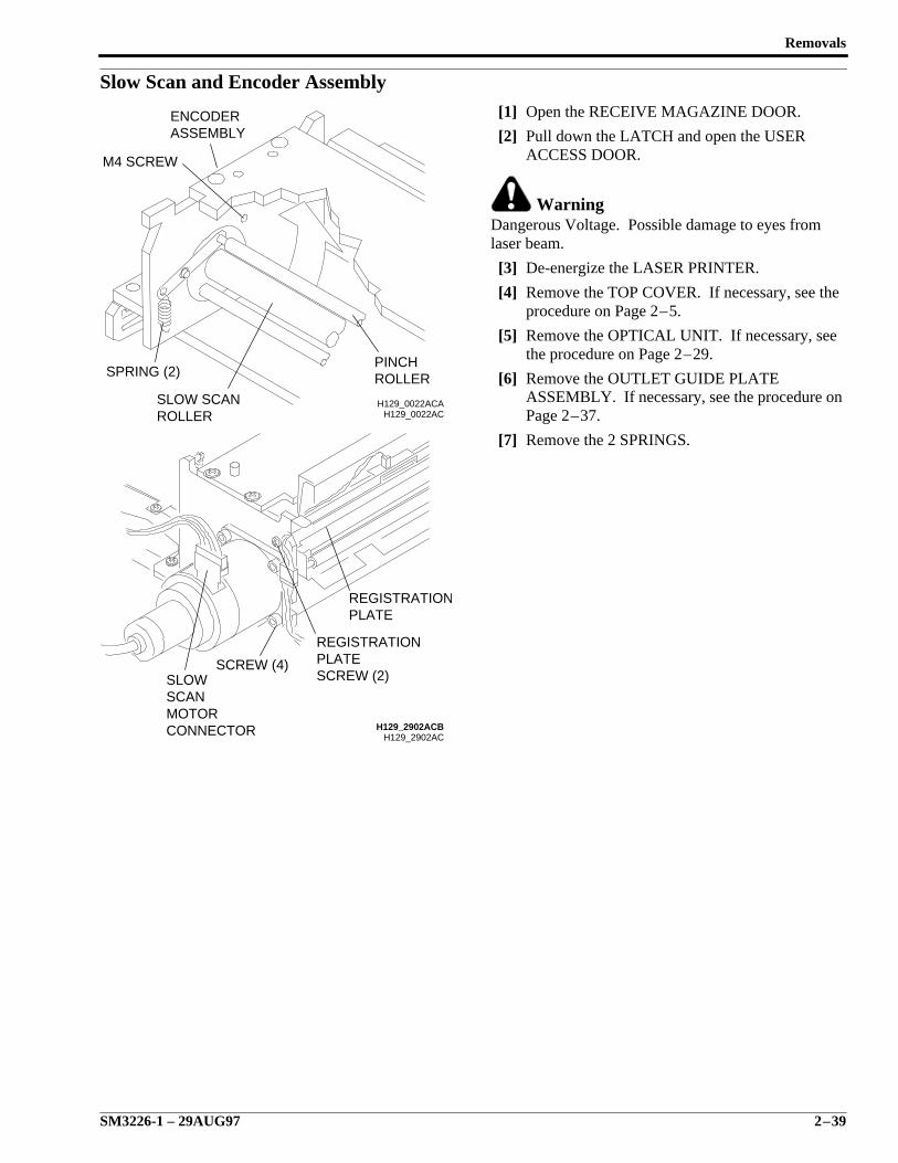
Slow Scan and Encoder Assembly[1] Open the RECEIVE MAGAZINE DOOR.
[2] Pull down the LATCH and open the USERACCESS DOOR.
WarningDangerous Voltage. Possible damage to eyes fromlaser beam.
[3] De-energize the LASER PRINTER.
[4] Remove the TOP COVER. If necessary, see theprocedure on Page 2–5.
[5] Remove the OPTICAL UNIT. If necessary, seethe procedure on Page 2–29.
[6] Remove the OUTLET GUIDE PLATEASSEMBLY. If necessary, see the procedure onPage 2–37.
[7] Remove the 2 SPRINGS.
H129_0022AC
M4 SCREW
ENCODERASSEMBLY
SPRING (2)
SLOW SCANROLLER
PINCHROLLER
H129_0022ACA
H129_2902ACCONNECTORMOTORSCANSLOW
PLATEREGISTRATION
SCREW (2)PLATEREGISTRATION
SCREW (4)
H129_2902ACB
SERVICE MANUAL
2–40 29AUG97 – SM3226-1
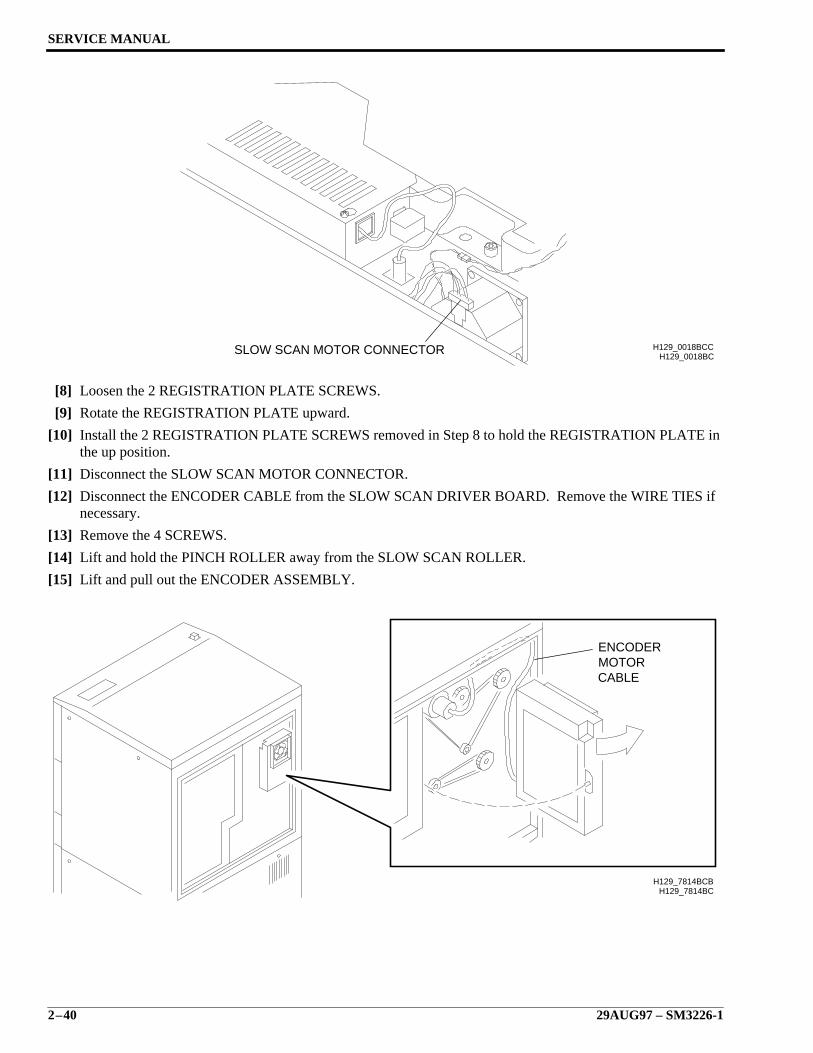
[8] Loosen the 2 REGISTRATION PLATE SCREWS.
[9] Rotate the REGISTRATION PLATE upward.
[10] Install the 2 REGISTRATION PLATE SCREWS removed in Step 8 to hold the REGISTRATION PLATE inthe up position.
[11] Disconnect the SLOW SCAN MOTOR CONNECTOR.
[12] Disconnect the ENCODER CABLE from the SLOW SCAN DRIVER BOARD. Remove the WIRE TIES ifnecessary.
[13] Remove the 4 SCREWS.
[14] Lift and hold the PINCH ROLLER away from the SLOW SCAN ROLLER.
[15] Lift and pull out the ENCODER ASSEMBLY.
H129_0018BCH129_0018BCCSLOW SCAN MOTOR CONNECTOR
H129_7814BC
CABLE
ENCODERMOTOR
H129_7814BCB
Removals
SM3226-1 – 29AUG97 2–41
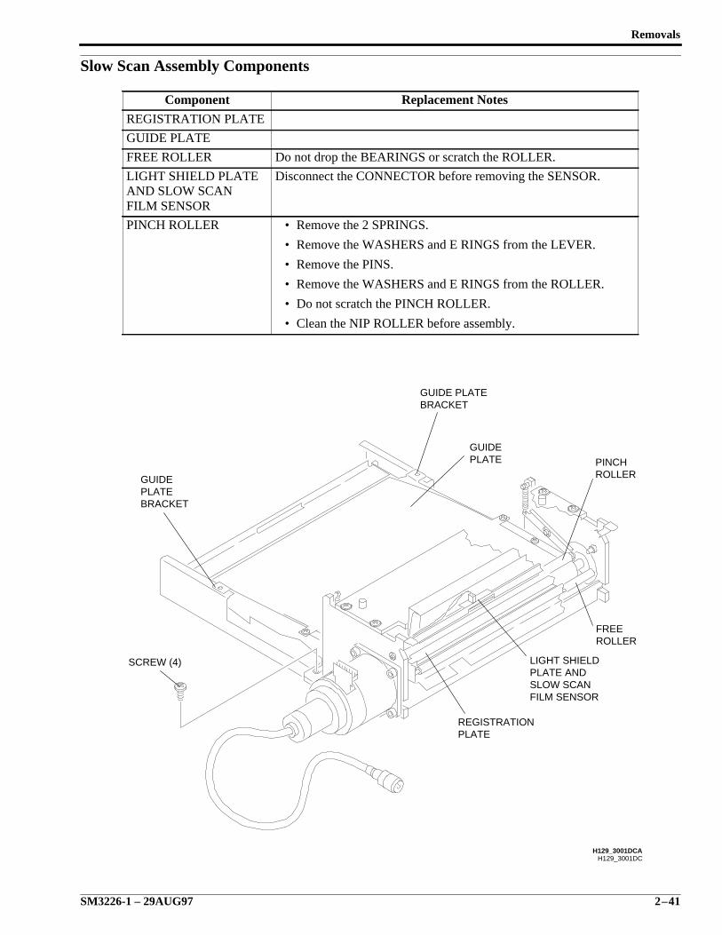
Slow Scan Assembly Components
Component Replacement Notes
REGISTRATION PLATE
GUIDE PLATE
FREE ROLLER Do not drop the BEARINGS or scratch the ROLLER.
LIGHT SHIELD PLATEAND SLOW SCANFILM SENSOR
Disconnect the CONNECTOR before removing the SENSOR.
PINCH ROLLER • Remove the 2 SPRINGS.
• Remove the WASHERS and E RINGS from the LEVER.
• Remove the PINS.
• Remove the WASHERS and E RINGS from the ROLLER.
• Do not scratch the PINCH ROLLER.
• Clean the NIP ROLLER before assembly.
H129_3001DC
BRACKETPLATEGUIDE
BRACKETGUIDE PLATE
H129_3001DCA
GUIDEPLATE PINCH
ROLLER
FREEROLLER
LIGHT SHIELDPLATE ANDSLOW SCANFILM SENSOR
REGISTRATIONPLATE
SCREW (4)
SERVICE MANUAL
2–42 29AUG97 – SM3226-1
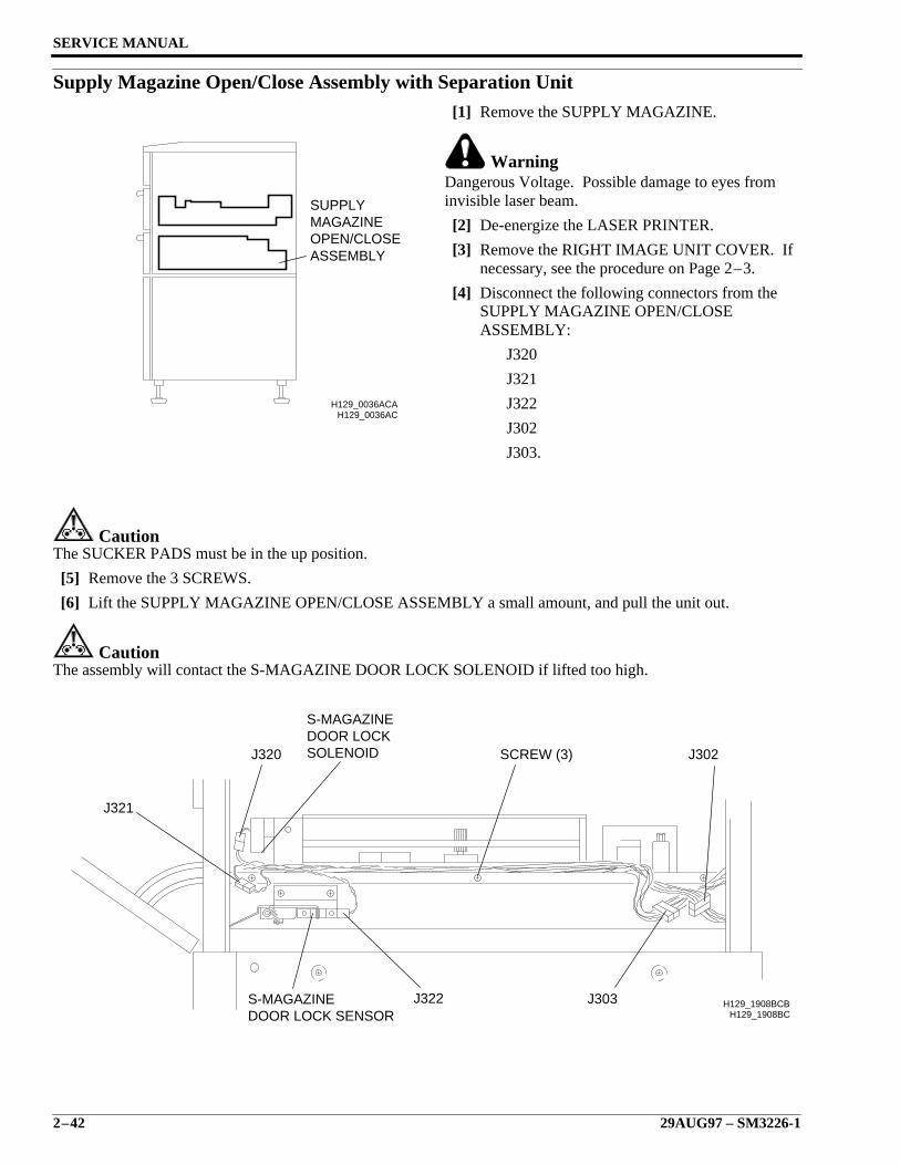
Supply Magazine Open/Close Assembly with Separation Unit[1] Remove the SUPPLY MAGAZINE.
WarningDangerous Voltage. Possible damage to eyes frominvisible laser beam.
[2] De-energize the LASER PRINTER.
[3] Remove the RIGHT IMAGE UNIT COVER. Ifnecessary, see the procedure on Page 2–3.
[4] Disconnect the following connectors from theSUPPLY MAGAZINE OPEN/CLOSEASSEMBLY:
J320
J321
J322
J302
J303.
CautionThe SUCKER PADS must be in the up position.
[5] Remove the 3 SCREWS.
[6] Lift the SUPPLY MAGAZINE OPEN/CLOSE ASSEMBLY a small amount, and pull the unit out.
CautionThe assembly will contact the S-MAGAZINE DOOR LOCK SOLENOID if lifted too high.
H129_0036ACH129_0036ACA
ASSEMBLYOPEN/CLOSEMAGAZINESUPPLY
H129_1908BC
SOLENOIDDOOR LOCKS-MAGAZINE
H129_1908BCB
J302SCREW (3)
J303J322
J320
J321
S-MAGAZINEDOOR LOCK SENSOR
Removals
SM3226-1 – 29AUG97 2–43
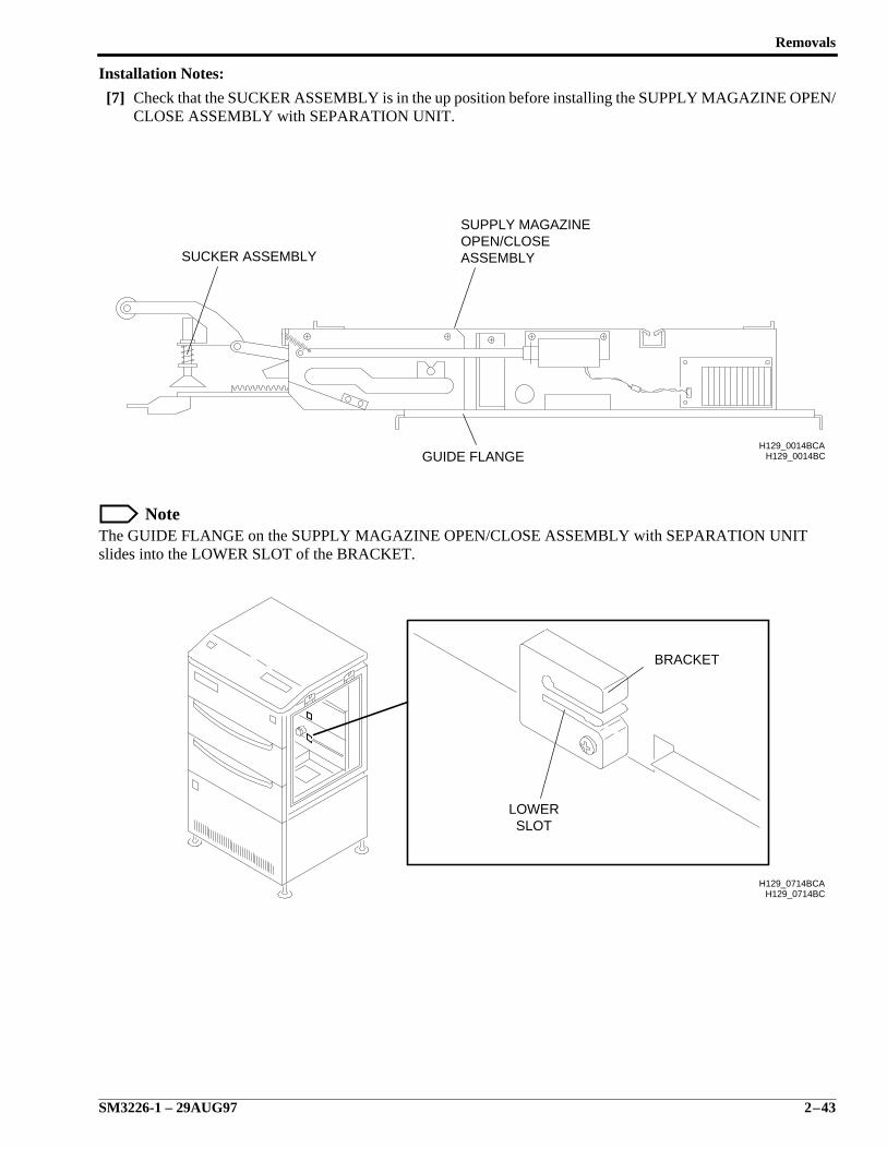
Installation Notes:
[7] Check that the SUCKER ASSEMBLY is in the up position before installing the SUPPLY MAGAZINE OPEN/CLOSE ASSEMBLY with SEPARATION UNIT.
NoteThe GUIDE FLANGE on the SUPPLY MAGAZINE OPEN/CLOSE ASSEMBLY with SEPARATION UNITslides into the LOWER SLOT of the BRACKET.
H129_0014BCH129_0014BCA
ASSEMBLYOPEN/CLOSESUPPLY MAGAZINE
GUIDE FLANGE
SUCKER ASSEMBLY
H129_0714BC
BRACKET
LOWERSLOT
H129_0714BCA
SERVICE MANUAL
2–44 29AUG97 – SM3226-1
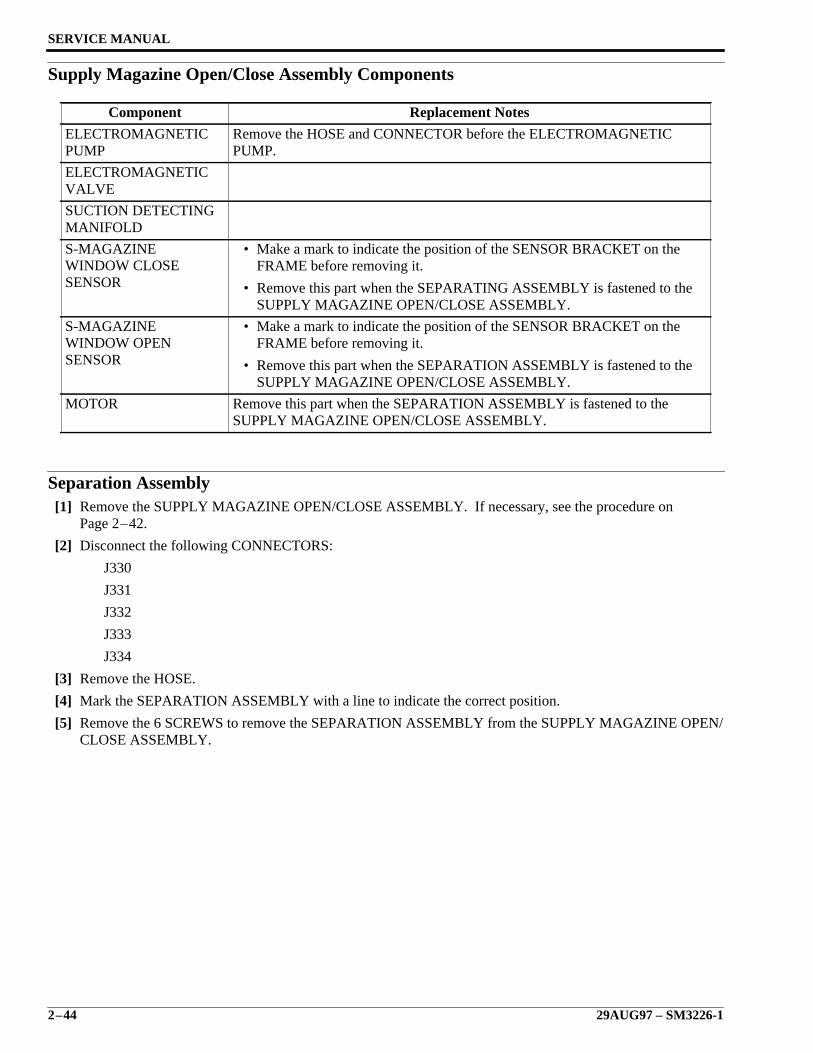
Supply Magazine Open/Close Assembly Components
Separation Assembly[1] Remove the SUPPLY MAGAZINE OPEN/CLOSE ASSEMBLY. If necessary, see the procedure on
Page 2–42.
[2] Disconnect the following CONNECTORS:
J330
J331
J332
J333
J334
[3] Remove the HOSE.
[4] Mark the SEPARATION ASSEMBLY with a line to indicate the correct position.
[5] Remove the 6 SCREWS to remove the SEPARATION ASSEMBLY from the SUPPLY MAGAZINE OPEN/CLOSE ASSEMBLY.
Component Replacement Notes
ELECTROMAGNETICPUMP
Remove the HOSE and CONNECTOR before the ELECTROMAGNETICPUMP.
ELECTROMAGNETICVALVE
SUCTION DETECTINGMANIFOLD
S-MAGAZINEWINDOW CLOSESENSOR
• Make a mark to indicate the position of the SENSOR BRACKET on theFRAME before removing it.
• Remove this part when the SEPARATING ASSEMBLY is fastened to theSUPPLY MAGAZINE OPEN/CLOSE ASSEMBLY.
S-MAGAZINEWINDOW OPENSENSOR
• Make a mark to indicate the position of the SENSOR BRACKET on theFRAME before removing it.
• Remove this part when the SEPARATION ASSEMBLY is fastened to theSUPPLY MAGAZINE OPEN/CLOSE ASSEMBLY.
MOTOR Remove this part when the SEPARATION ASSEMBLY is fastened to theSUPPLY MAGAZINE OPEN/CLOSE ASSEMBLY.
Removals
SM3226-1 – 29AUG97 2–45
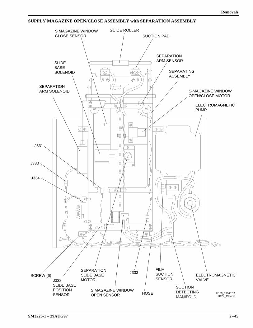
SUPPLY MAGAZINE OPEN/CLOSE ASSEMBLY with SEPARATION ASSEMBLY
H129_1904EC
SENSORSUCTIONFILM
ARM SOLENOIDSEPARATION
GUIDE ROLLER
SUCTION PAD
SEPARATIONARM SENSOR
SEPARATINGASSEMBLY
ELECTROMAGNETICPUMP
SEPARATIONSLIDE BASEMOTOR
ELECTROMAGNETICVALVE
SUCTIONDETECTINGMANIFOLD
HOSE
J333
S MAGAZINE WINDOWOPEN SENSOR
J332SLIDE BASEPOSITIONSENSOR
SCREW (6)
J334
J331
J330
SLIDEBASESOLENOID
S MAGAZINE WINDOWCLOSE SENSOR
H129_1904ECA
S-MAGAZINE WINDOWOPEN/CLOSE MOTOR

SERVICE MANUAL
2–46 29AUG97 – SM3226-1
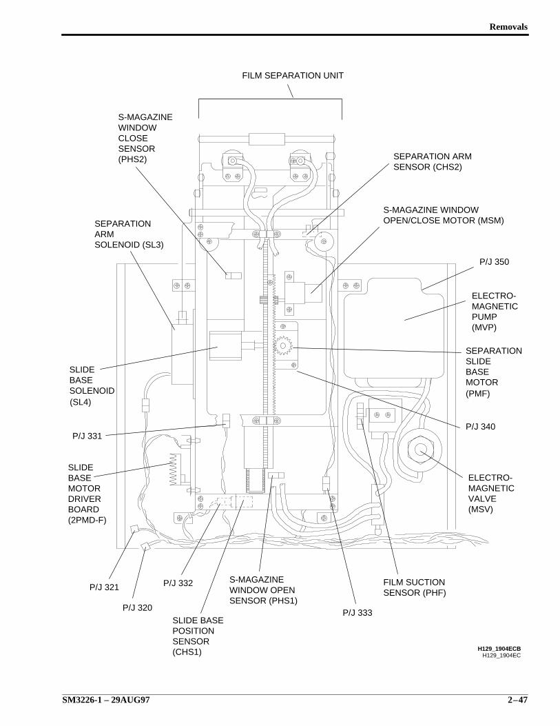
Separation Assembly Components
Component Replacement Notes
SLIDE BASE MOTOR
SLIDE BASE SOLENOID
SEPARATION ARMSOLENOID
It is not necessary to remove the SEPARATION ASSEMBLY from the BASEPLATE to remove these components.
FILM SUCTIONSENSOR
SLIDE BASE POSITIONSENSOR
GUIDE ROLLER Remove both GUIDE ROLLERS.
SLIDE BASE • Remove the LINK MECHANISM with the SLIDE BASE.
• Keep the WASHERS.
SUCTION PAD It is not necessary to remove the SEPARATING UNIT to remove the SUCTIONPAD.
Removals
SM3226-1 – 29AUG97 2–47
H129_1904EC
FILM SEPARATION UNIT
SENSOR (PHS1)
BASE
P/J 320
P/J 321
(SL4)
P/J 331
(2PMD-F)BOARD DRIVERMOTORBASESLIDE
SOLENOID
P/J 332 S-MAGAZINE
SLIDE BASE
(CHS1)SENSORPOSITION
WINDOW OPEN
SENSOR
WINDOW
SEPARATION
S-MAGAZINE
SLIDE
SOLENOID (SL3)ARM
CLOSE
(PHS2)
SENSOR (PHF)FILM SUCTION
P/J 333
H129_1904ECB
ELECTRO-
(MSV)VALVEMAGNETIC
P/J 340
(PMF)MOTOR
SENSOR (CHS2)SEPARATION ARM
OPEN/CLOSE MOTOR (MSM)S-MAGAZINE WINDOW
SEPARATION
MAGNETICELECTRO-
P/J 350
PUMP(MVP)
BASESLIDE
SERVICE MANUAL
2–48 29AUG97 – SM3226-1
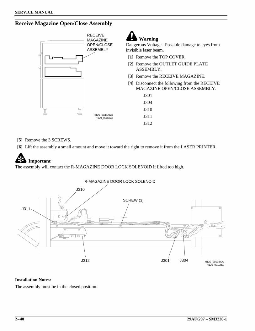
Receive Magazine Open/Close Assembly
WarningDangerous Voltage. Possible damage to eyes frominvisible laser beam.
[1] Remove the TOP COVER.
[2] Remove the OUTLET GUIDE PLATEASSEMBLY.
[3] Remove the RECEIVE MAGAZINE.
[4] Disconnect the following from the RECEIVEMAGAZINE OPEN/CLOSE ASSEMBLY:
J301
J304
J310
J311
J312
[5] Remove the 3 SCREWS.
[6] Lift the assembly a small amount and move it toward the right to remove it from the LASER PRINTER.
ImportantThe assembly will contact the R-MAGAZINE DOOR LOCK SOLENOID if lifted too high.
Installation Notes:
The assembly must be in the closed position.
H129_0036ACH129_0036ACB
ASSEMBLYOPEN/CLOSEMAGAZINERECEIVE
H129_0019BC
R-MAGAZINE DOOR LOCK SOLENOID
J311
J310
J312 J304J301
SCREW (3)
H129_0019BCA
Removals
SM3226-1 – 29AUG97 2–49
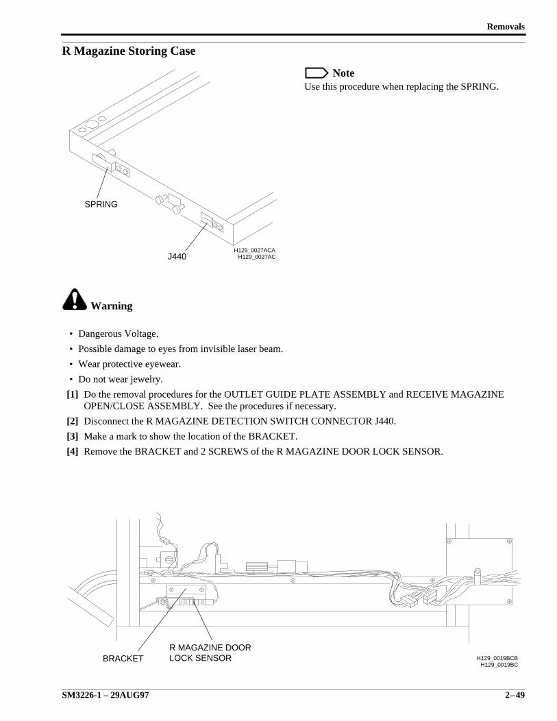
R Magazine Storing Case
NoteUse this procedure when replacing the SPRING.
Warning
• Dangerous Voltage.
• Possible damage to eyes from invisible laser beam.
• Wear protective eyewear.
• Do not wear jewelry.
[1] Do the removal procedures for the OUTLET GUIDE PLATE ASSEMBLY and RECEIVE MAGAZINEOPEN/CLOSE ASSEMBLY. See the procedures if necessary.
[2] Disconnect the R MAGAZINE DETECTION SWITCH CONNECTOR J440.
[3] Make a mark to show the location of the BRACKET.
[4] Remove the BRACKET and 2 SCREWS of the R MAGAZINE DOOR LOCK SENSOR.
H129_0027ACH129_0027ACA
J440
SPRING
H129_0019BCBRACKET
R MAGAZINE DOORLOCK SENSOR H129_0019BCB
SERVICE MANUAL
2–50 29AUG97 – SM3226-1
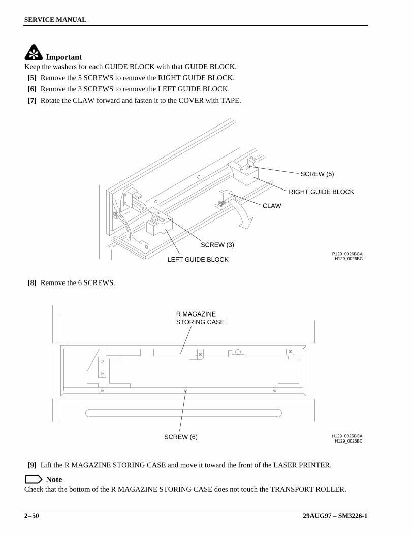
ImportantKeep the washers for each GUIDE BLOCK with that GUIDE BLOCK.
[5] Remove the 5 SCREWS to remove the RIGHT GUIDE BLOCK.
[6] Remove the 3 SCREWS to remove the LEFT GUIDE BLOCK.
[7] Rotate the CLAW forward and fasten it to the COVER with TAPE.
[8] Remove the 6 SCREWS.
[9] Lift the R MAGAZINE STORING CASE and move it toward the front of the LASER PRINTER.
NoteCheck that the bottom of the R MAGAZINE STORING CASE does not touch the TRANSPORT ROLLER.
H129_0026BCP129_0026BCA
LEFT GUIDE BLOCK
SCREW (3)
CLAW
RIGHT GUIDE BLOCK
SCREW (5)
H129_0025BCH129_0025BCA
STORING CASER MAGAZINE
SCREW (6)
Removals
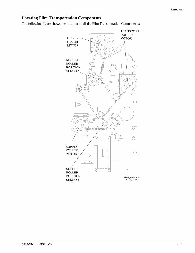
SM3226-1 – 29AUG97 2–51
Locating Film Transportation ComponentsThe following figure shows the location of all the Film Transportation Components:
H129_0028CCH129_0028CCA
SENSORPOSITIONROLLERSUPPLY
MOTORROLLERSUPPLY
SENSORPOSITIONROLLERRECEIVE
MOTORROLLERTRANSPORT
MOTORROLLERRECEIVE
SERVICE MANUAL
2–52 29AUG97 – SM3226-1
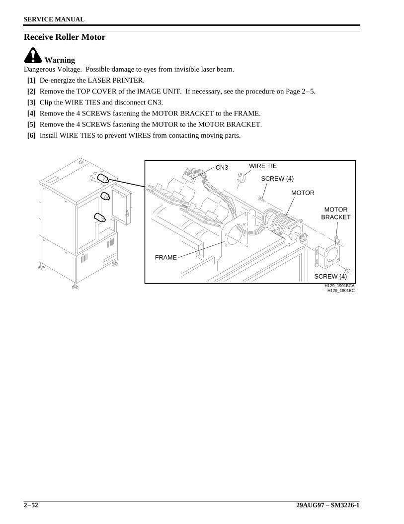
Receive Roller Motor
WarningDangerous Voltage. Possible damage to eyes from invisible laser beam.
[1] De-energize the LASER PRINTER.
[2] Remove the TOP COVER of the IMAGE UNIT. If necessary, see the procedure on Page 2–5.
[3] Clip the WIRE TIES and disconnect CN3.
[4] Remove the 4 SCREWS fastening the MOTOR BRACKET to the FRAME.
[5] Remove the 4 SCREWS fastening the MOTOR to the MOTOR BRACKET.
[6] Install WIRE TIES to prevent WIRES from contacting moving parts.
H129_1901BCH129_1901BCA
BRACKETMOTOR
MOTOR
SCREW (4)
SCREW (4)
WIRE TIECN3
FRAME
Removals
SM3226-1 – 29AUG97 2–53
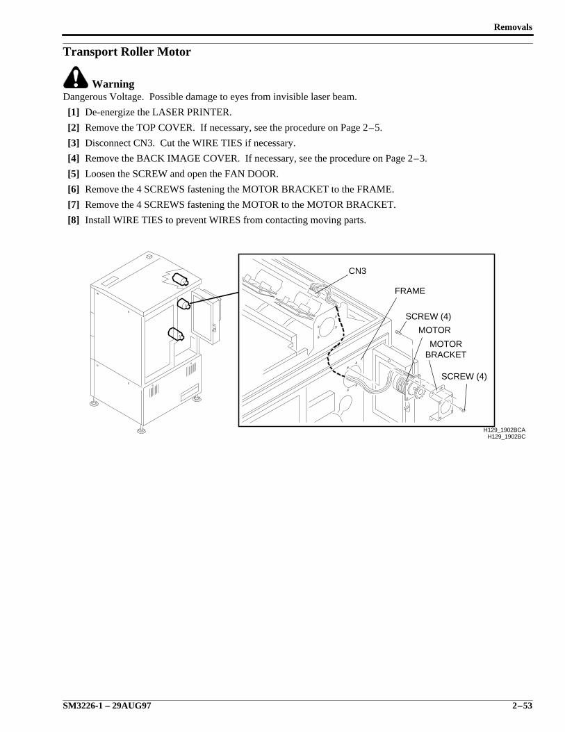
Transport Roller Motor
WarningDangerous Voltage. Possible damage to eyes from invisible laser beam.
[1] De-energize the LASER PRINTER.
[2] Remove the TOP COVER. If necessary, see the procedure on Page 2–5.
[3] Disconnect CN3. Cut the WIRE TIES if necessary.
[4] Remove the BACK IMAGE COVER. If necessary, see the procedure on Page 2–3.
[5] Loosen the SCREW and open the FAN DOOR.
[6] Remove the 4 SCREWS fastening the MOTOR BRACKET to the FRAME.
[7] Remove the 4 SCREWS fastening the MOTOR to the MOTOR BRACKET.
[8] Install WIRE TIES to prevent WIRES from contacting moving parts.
H129_1902BCH129_1902BCA
CN3
FRAME
SCREW (4)
SCREW (4)
MOTOR
MOTORBRACKET
SERVICE MANUAL
2–54 29AUG97 – SM3226-1
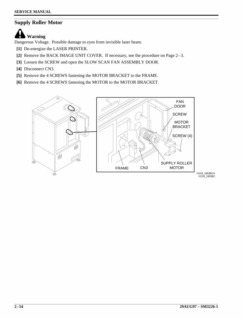
Supply Roller Motor
WarningDangerous Voltage. Possible damage to eyes from invisible laser beam.
[1] De-energize the LASER PRINTER.
[2] Remove the BACK IMAGE UNIT COVER. If necessary, see the procedure on Page 2–3.
[3] Loosen the SCREW and open the SLOW SCAN FAN ASSEMBLY DOOR.
[4] Disconnect CN3.
[5] Remove the 4 SCREWS fastening the MOTOR BRACKET to the FRAME.
[6] Remove the 4 SCREWS fastening the MOTOR to the MOTOR BRACKET.
H129_1903BCH129_1903BCA
MOTORSUPPLY ROLLER
CN3FRAME
SCREW (4)
BRACKETMOTOR
SCREW
DOORFAN

Diagnostic Check Procedures
SM3226-1 – 29AUG97 3–1
Section 3: Diagnostic Check Procedures
Description Page
Table of Contents
Setting up the Optical Power Meter . . . . . . . . . . . . . . . . . . . . . . . . . . . . . . . . . . . . . . 3-2Measuring the Laser Power . . . . . . . . . . . . . . . . . . . . . . . . . . . . . . . . . . . . . . . . . . . . . 3-4Checking Vacuum Pressure. . . . . . . . . . . . . . . . . . . . . . . . . . . . . . . . . . . . . . . . . . . . . 3-10
SERVICE MANUAL
3–2 29AUG97 – SM3226-1
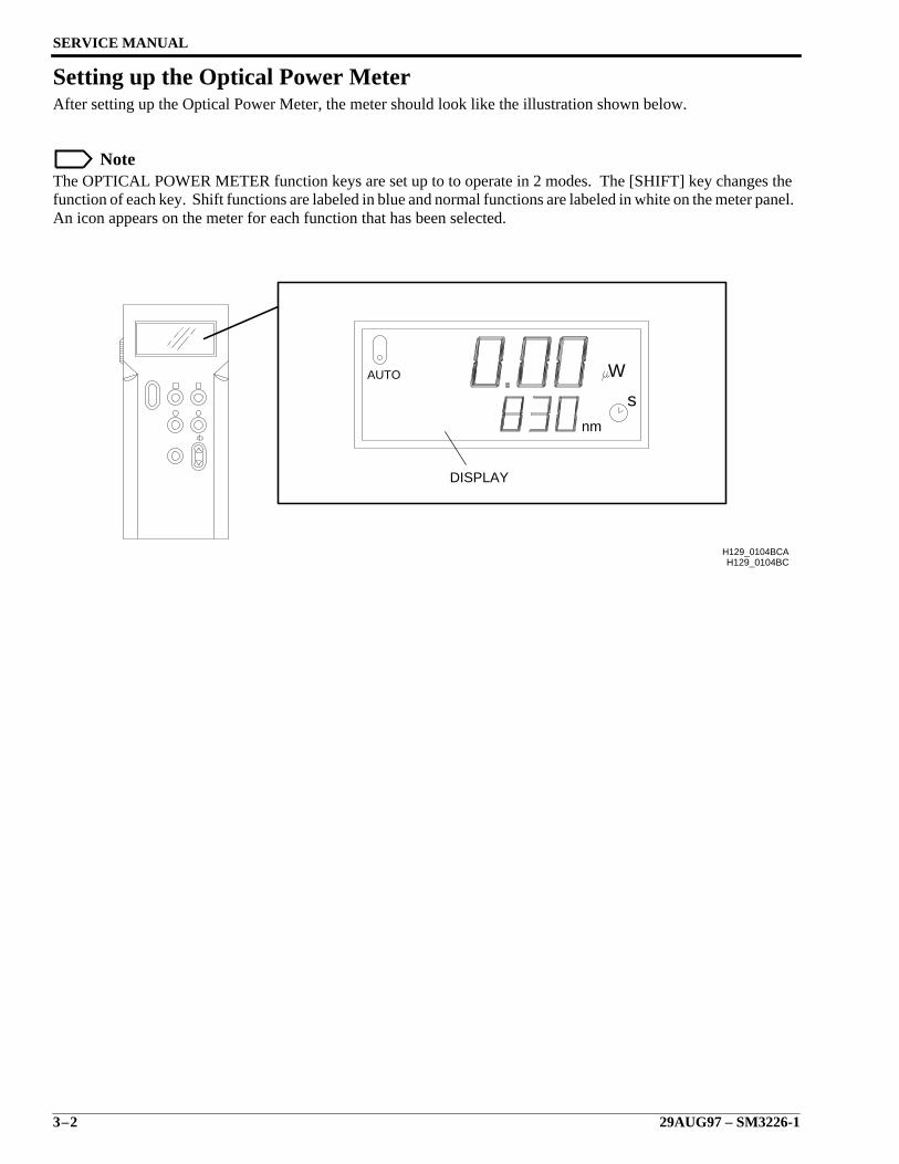
Setting up the Optical Power MeterAfter setting up the Optical Power Meter, the meter should look like the illustration shown below.
NoteThe OPTICAL POWER METER function keys are set up to to operate in 2 modes. The [SHIFT] key changes thefunction of each key. Shift functions are labeled in blue and normal functions are labeled in white on the meter panel.An icon appears on the meter for each function that has been selected.
H129_0104BC
AUTO
s
W
nm
H129_0104BCA
DISPLAY
Diagnostic Check Procedures
SM3226-1 – 29AUG97 3–3
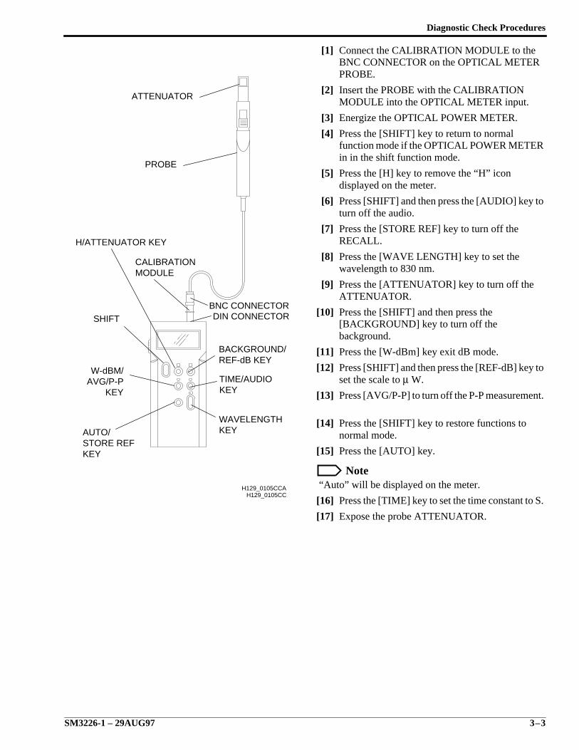
[1] Connect the CALIBRATION MODULE to theBNC CONNECTOR on the OPTICAL METERPROBE.
[2] Insert the PROBE with the CALIBRATIONMODULE into the OPTICAL METER input.
[3] Energize the OPTICAL POWER METER.
[4] Press the [SHIFT] key to return to normalfunction mode if the OPTICAL POWER METERin in the shift function mode.
[5] Press the [H] key to remove the “H” icondisplayed on the meter.
[6] Press [SHIFT] and then press the [AUDIO] key toturn off the audio.
[7] Press the [STORE REF] key to turn off theRECALL.
[8] Press the [WAVE LENGTH] key to set thewavelength to 830 nm.
[9] Press the [ATTENUATOR] key to turn off theATTENUATOR.
[10] Press the [SHIFT] and then press the[BACKGROUND] key to turn off thebackground.
[11] Press the [W-dBm] key exit dB mode.
[12] Press [SHIFT] and then press the [REF-dB] key toset the scale to µ W.
[13] Press [AVG/P-P] to turn off the P-P measurement.
[14] Press the [SHIFT] key to restore functions tonormal mode.
[15] Press the [AUTO] key.
Note “Auto” will be displayed on the meter.
[16] Press the [TIME] key to set the time constant to S.
[17] Expose the probe ATTENUATOR.
H129_0105CC
KEYAVG/P-PW-dBM/
DIN CONNECTOR
ATTENUATOR
PROBE
SHIFT
H/ATTENUATOR KEY
CALIBRATIONMODULE
WAVELENGTHKEY
TIME/AUDIOKEY
BACKGROUND/REF-dB KEY
BNC CONNECTOR
AUTO/STORE REFKEY
H129_0105CCA
SERVICE MANUAL
3–4 29AUG97 – SM3226-1
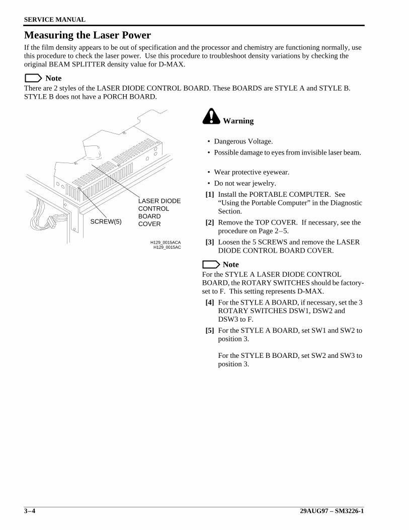
Measuring the Laser PowerIf the film density appears to be out of specification and the processor and chemistry are functioning normally, usethis procedure to check the laser power. Use this procedure to troubleshoot density variations by checking theoriginal BEAM SPLITTER density value for D-MAX.
NoteThere are 2 styles of the LASER DIODE CONTROL BOARD. These BOARDS are STYLE A and STYLE B.STYLE B does not have a PORCH BOARD.
Warning
• Dangerous Voltage.
• Possible damage to eyes from invisible laser beam.
• Wear protective eyewear.
• Do not wear jewelry.
[1] Install the PORTABLE COMPUTER. See“Using the Portable Computer” in the DiagnosticSection.
[2] Remove the TOP COVER. If necessary, see theprocedure on Page 2–5.
[3] Loosen the 5 SCREWS and remove the LASERDIODE CONTROL BOARD COVER.
NoteFor the STYLE A LASER DIODE CONTROLBOARD, the ROTARY SWITCHES should be factory-set to F. This setting represents D-MAX.
[4] For the STYLE A BOARD, if necessary, set the 3ROTARY SWITCHES DSW1, DSW2 andDSW3 to F.
[5] For the STYLE A BOARD, set SW1 and SW2 toposition 3.
For the STYLE B BOARD, set SW2 and SW3 toposition 3.
H129_0015AC
COVERBOARDCONTROLLASER DIODE
SCREW(5)
H129_0015ACA
Diagnostic Check Procedures
SM3226-1 – 29AUG97 3–5
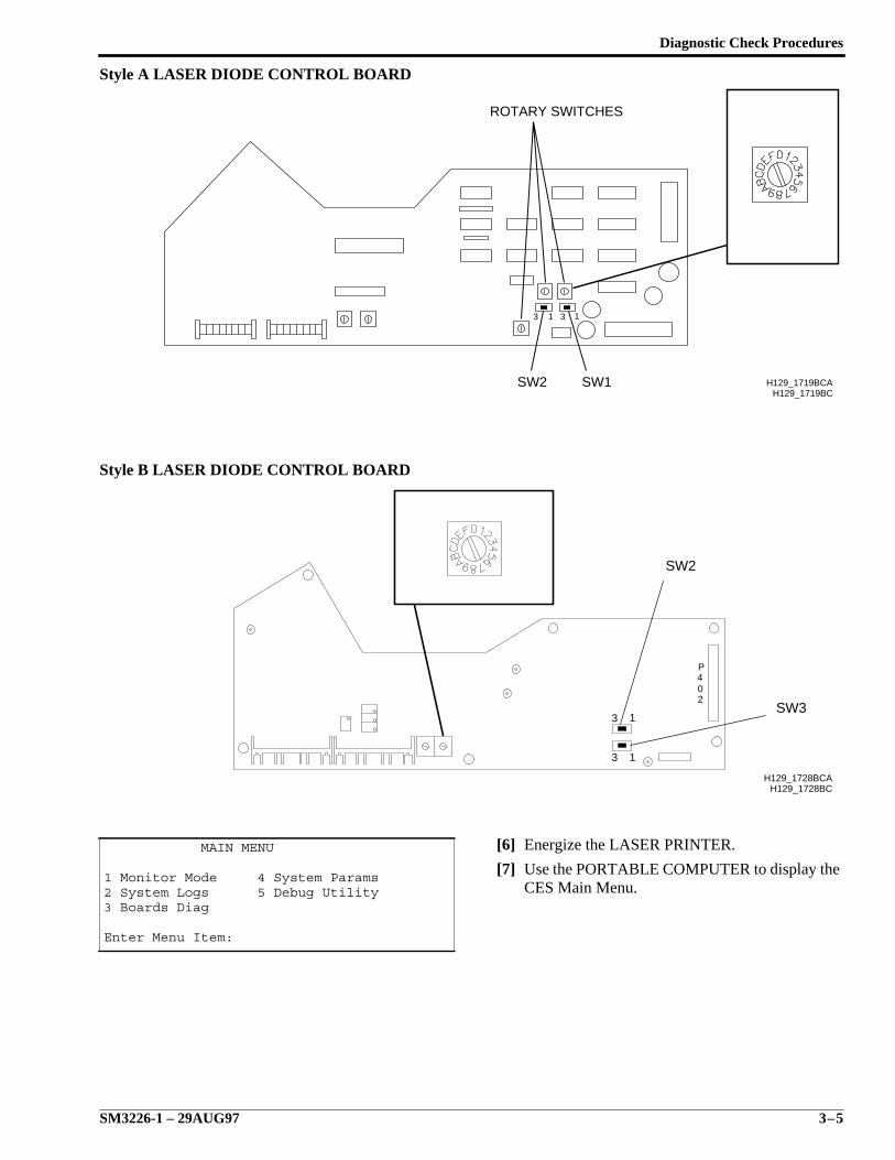
Style A LASER DIODE CONTROL BOARD
Style B LASER DIODE CONTROL BOARD
[6] Energize the LASER PRINTER.
[7] Use the PORTABLE COMPUTER to display theCES Main Menu.
MAIN MENU
1 Monitor Mode 4 System Params2 System Logs 5 Debug Utility3 Boards Diag
Enter Menu Item:
1313
H129_1719BC
ROTARY SWITCHES
SW1SW2 H129_1719BCA
3 1
3 1
P402
H129_1728BCH129_1728BCA
SW3
SW2
SERVICE MANUAL
3–6 29AUG97 – SM3226-1
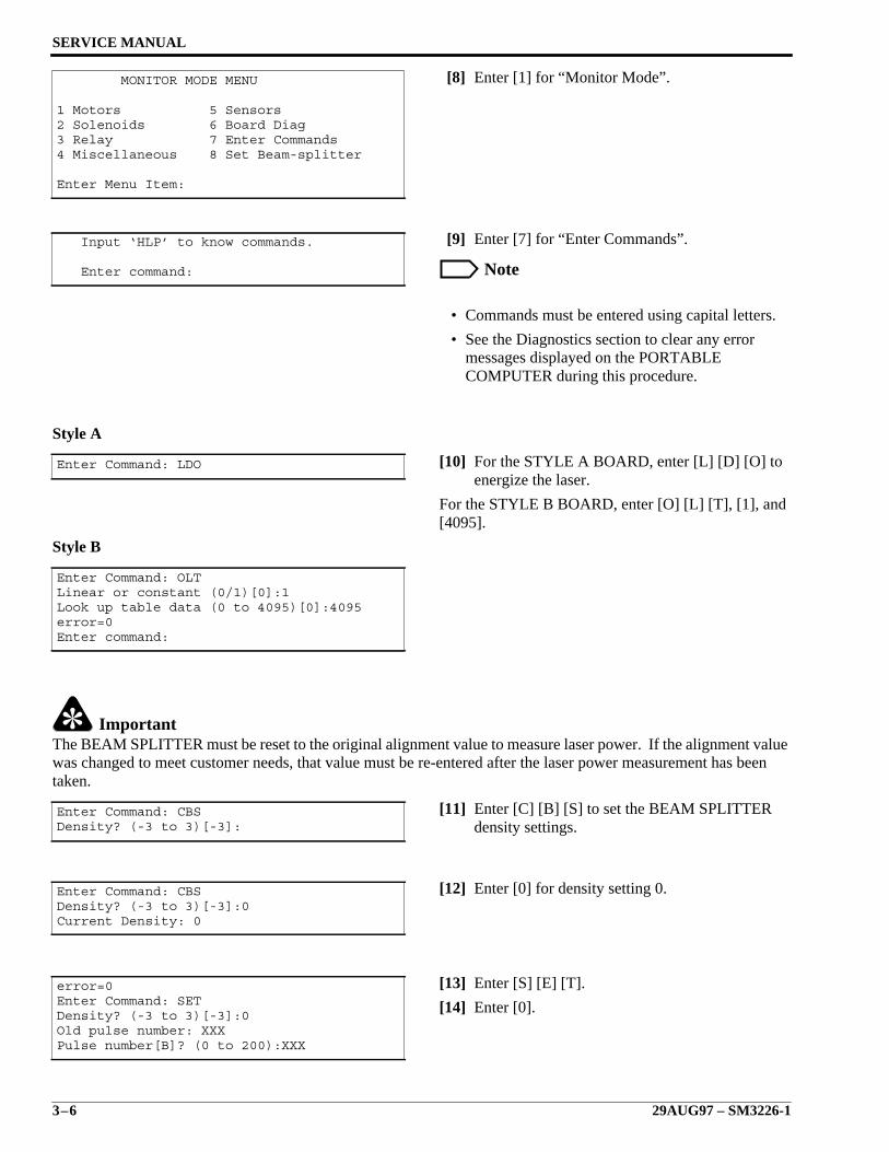
[8] Enter [1] for “Monitor Mode”.
[9] Enter [7] for “Enter Commands”.
Note
• Commands must be entered using capital letters.
• See the Diagnostics section to clear any errormessages displayed on the PORTABLECOMPUTER during this procedure.
Style A
[10] For the STYLE A BOARD, enter [L] [D] [O] toenergize the laser.
For the STYLE B BOARD, enter [O] [L] [T], [1], and[4095].
Style B
ImportantThe BEAM SPLITTER must be reset to the original alignment value to measure laser power. If the alignment valuewas changed to meet customer needs, that value must be re-entered after the laser power measurement has beentaken.
[11] Enter [C] [B] [S] to set the BEAM SPLITTERdensity settings.
[12] Enter [0] for density setting 0.
[13] Enter [S] [E] [T].
[14] Enter [0].
MONITOR MODE MENU
1 Motors 5 Sensors2 Solenoids 6 Board Diag3 Relay 7 Enter Commands4 Miscellaneous 8 Set Beam-splitter
Enter Menu Item:
Input ‘HLP’ to know commands.
Enter command:
Enter Command: LDO
Enter Command: OLTLinear or constant (0/1)[0]:1Look up table data (0 to 4095)[0]:4095error=0Enter command:
Enter Command: CBSDensity? (-3 to 3)[-3]:
Enter Command: CBSDensity? (-3 to 3)[-3]:0Current Density: 0
error=0Enter Command: SETDensity? (-3 to 3)[-3]:0Old pulse number: XXXPulse number[B]? (0 to 200):XXX
Diagnostic Check Procedures
SM3226-1 – 29AUG97 3–7
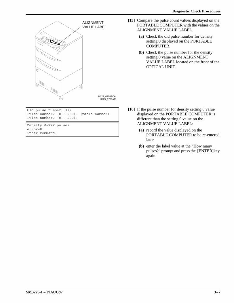
[15] Compare the pulse count values displayed on thePORTABLE COMPUTER with the values on theALIGNMENT VALUE LABEL.
(a) Check the old pulse number for densitysetting 0 displayed on the PORTABLECOMPUTER.
(b) Check the pulse number for the densitysetting 0 value on the ALIGNMENTVALUE LABEL located on the front of theOPTICAL UNIT.
[16] If the pulse number for density setting 0 valuedisplayed on the PORTABLE COMPUTER isdifferent than the setting 0 value on theALIGNMENT VALUE LABEL:
(a) record the value displayed on thePORTABLE COMPUTER to be re-enteredlater
(b) enter the label value at the “How manypulses?” prompt and press the [ENTER]keyagain.
Old pulse number: XXXPulse number? (0 - 200): (table number)Pulse number? (0 - 200):
Density 0=XXX pulseserror=0Enter Command:
H129_0708AC
VALUE LABELALIGNMENT
H129_0708ACA
SERVICE MANUAL
3–8 29AUG97 – SM3226-1
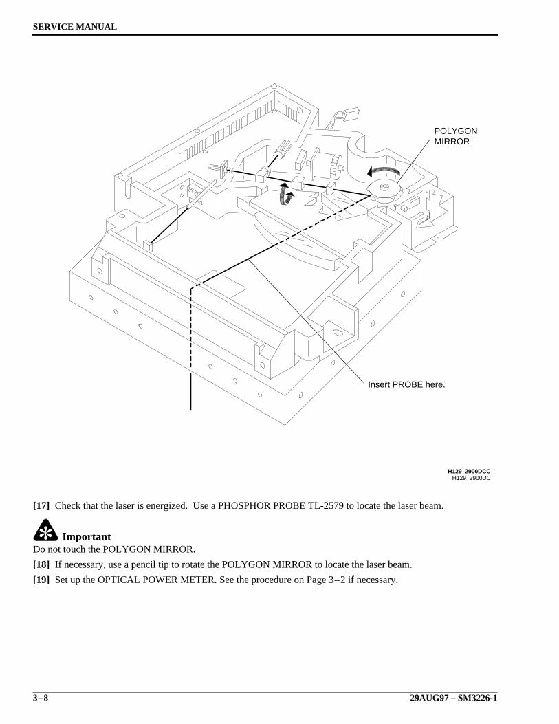
[17] Check that the laser is energized. Use a PHOSPHOR PROBE TL-2579 to locate the laser beam.
ImportantDo not touch the POLYGON MIRROR.
[18] If necessary, use a pencil tip to rotate the POLYGON MIRROR to locate the laser beam.
[19] Set up the OPTICAL POWER METER. See the procedure on Page 3–2 if necessary.
H129_2900DC
MIRRORPOLYGON
Insert PROBE here.
H129_2900DCC
Diagnostic Check Procedures
SM3226-1 – 29AUG97 3–9
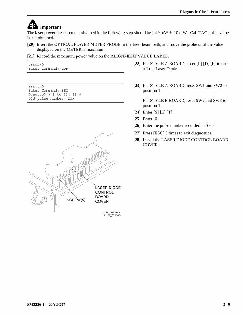
ImportantThe laser power measurement obtained in the following step should be 1.49 mW ± .10 mW. Call TAC if this valueis not obtained.
[20] Insert the OPTICAL POWER METER PROBE in the laser beam path, and move the probe until the valuedisplayed on the METER is maximum.
[21] Record the maximum power value on the ALIGNMENT VALUE LABEL.
[22] For STYLE A BOARD, enter [L] [D] [F] to turnoff the Laser Diode.
[23] For STYLE A BOARD, reset SW1 and SW2 toposition 1.
For STYLE B BOARD, reset SW2 and SW3 toposition 1.
[24] Enter [S] [E] [T].
[25] Enter [0].
[26] Enter the pulse number recorded in Step .
[27] Press [ESC] 3 times to exit diagnostics.
[28] Install the LASER DIODE CONTROL BOARDCOVER.
error=0Enter Command: LDF
error=0Enter Command: SETDensity? (-3 to 3)[-3]:0Old pulse number: XXX
H129_0015AC
COVERBOARDCONTROLLASER DIODE
SCREW(5)
H129_0015ACA
SERVICE MANUAL
3–10 29AUG97 – SM3226-1
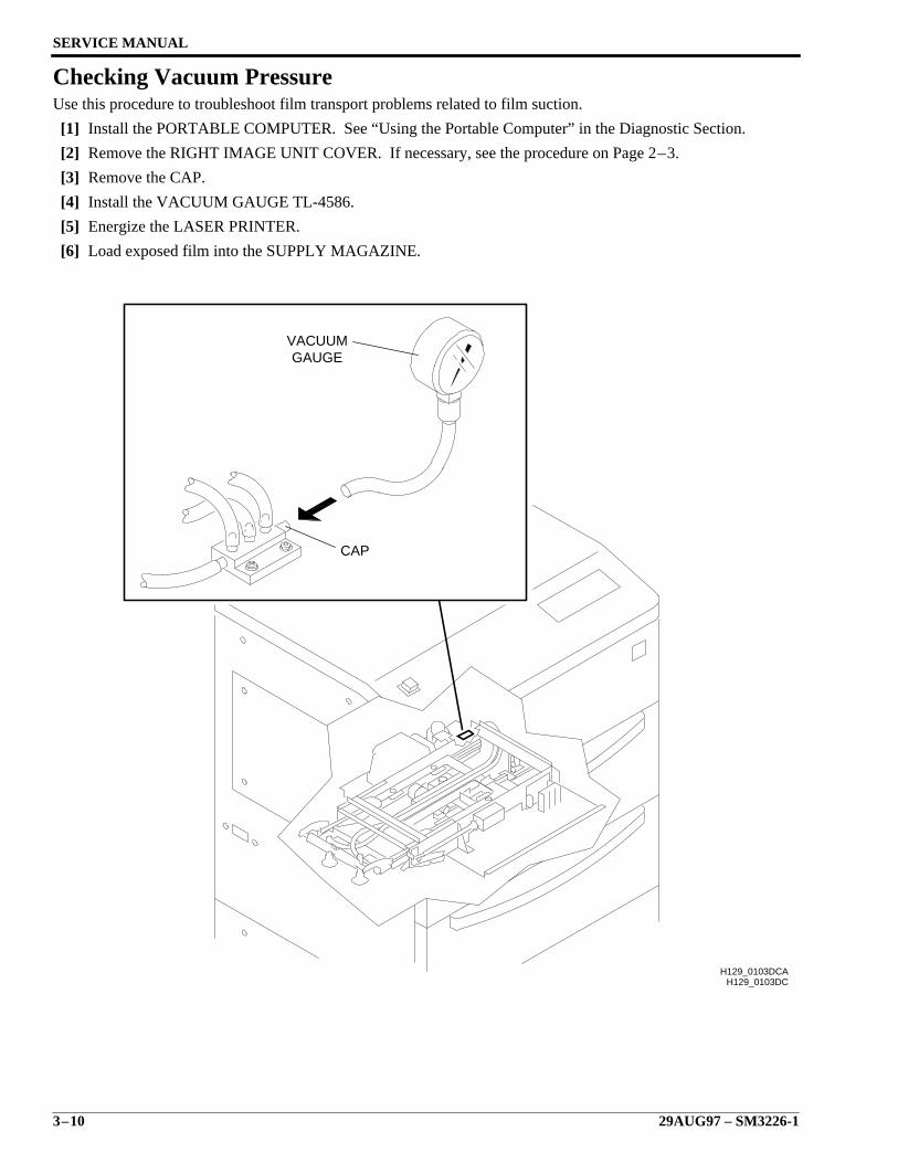
Checking Vacuum PressureUse this procedure to troubleshoot film transport problems related to film suction.
[1] Install the PORTABLE COMPUTER. See “Using the Portable Computer” in the Diagnostic Section.
[2] Remove the RIGHT IMAGE UNIT COVER. If necessary, see the procedure on Page 2–3.
[3] Remove the CAP.
[4] Install the VACUUM GAUGE TL-4586.
[5] Energize the LASER PRINTER.
[6] Load exposed film into the SUPPLY MAGAZINE.
H129_0103DCH129_0103DCA
CAP
GAUGEVACUUM
Diagnostic Check Procedures
SM3226-1 – 29AUG97 3–11
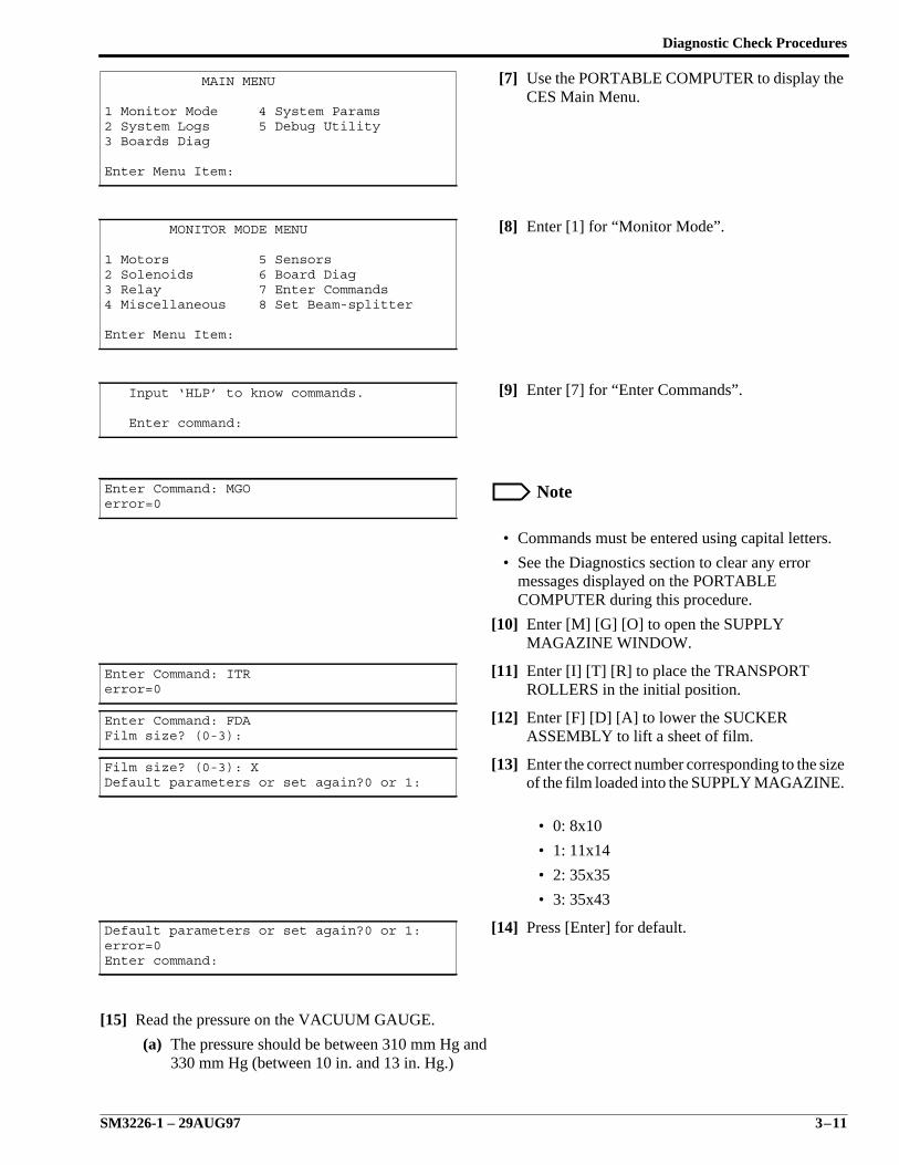
[7] Use the PORTABLE COMPUTER to display theCES Main Menu.
[8] Enter [1] for “Monitor Mode”.
[9] Enter [7] for “Enter Commands”.
Note
• Commands must be entered using capital letters.
• See the Diagnostics section to clear any errormessages displayed on the PORTABLECOMPUTER during this procedure.
[10] Enter [M] [G] [O] to open the SUPPLYMAGAZINE WINDOW.
[11] Enter [I] [T] [R] to place the TRANSPORTROLLERS in the initial position.
[12] Enter [F] [D] [A] to lower the SUCKERASSEMBLY to lift a sheet of film.
[13] Enter the correct number corresponding to the sizeof the film loaded into the SUPPLY MAGAZINE.
• 0: 8x10
• 1: 11x14
• 2: 35x35
• 3: 35x43
[14] Press [Enter] for default.
[15] Read the pressure on the VACUUM GAUGE.
(a) The pressure should be between 310 mm Hg and330 mm Hg (between 10 in. and 13 in. Hg.)
MAIN MENU
1 Monitor Mode 4 System Params2 System Logs 5 Debug Utility3 Boards Diag
Enter Menu Item:
MONITOR MODE MENU
1 Motors 5 Sensors2 Solenoids 6 Board Diag3 Relay 7 Enter Commands4 Miscellaneous 8 Set Beam-splitter
Enter Menu Item:
Input ‘HLP’ to know commands.
Enter command:
Enter Command: MGOerror=0
Enter Command: ITRerror=0
Enter Command: FDAFilm size? (0-3):
Film size? (0-3): XDefault parameters or set again?0 or 1:
Default parameters or set again?0 or 1:error=0Enter command:
SERVICE MANUAL
3–12 29AUG97 – SM3226-1
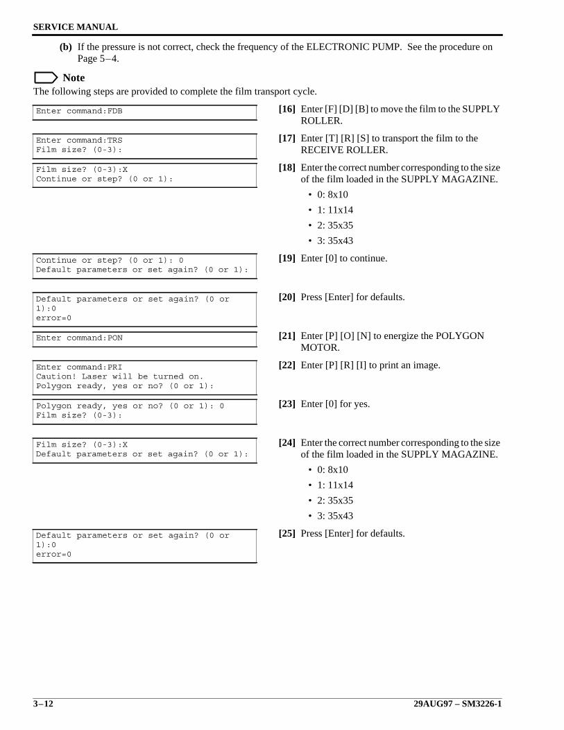
(b) If the pressure is not correct, check the frequency of the ELECTRONIC PUMP. See the procedure onPage 5–4.
NoteThe following steps are provided to complete the film transport cycle.
[16] Enter [F] [D] [B] to move the film to the SUPPLYROLLER.
[17] Enter [T] [R] [S] to transport the film to theRECEIVE ROLLER.
[18] Enter the correct number corresponding to the sizeof the film loaded in the SUPPLY MAGAZINE.
• 0: 8x10
• 1: 11x14
• 2: 35x35
• 3: 35x43
[19] Enter [0] to continue.
[20] Press [Enter] for defaults.
[21] Enter [P] [O] [N] to energize the POLYGONMOTOR.
[22] Enter [P] [R] [I] to print an image.
[23] Enter [0] for yes.
[24] Enter the correct number corresponding to the sizeof the film loaded in the SUPPLY MAGAZINE.
• 0: 8x10
• 1: 11x14
• 2: 35x35
• 3: 35x43
[25] Press [Enter] for defaults.
Enter command:FDB
Enter command:TRSFilm size? (0-3):
Film size? (0-3):XContinue or step? (0 or 1):
Continue or step? (0 or 1): 0Default parameters or set again? (0 or 1):
Default parameters or set again? (0 or1):0error=0
Enter command:PON
Enter command:PRICaution! Laser will be turned on.Polygon ready, yes or no? (0 or 1):
Polygon ready, yes or no? (0 or 1): 0Film size? (0-3):
Film size? (0-3):XDefault parameters or set again? (0 or 1):
Default parameters or set again? (0 or1):0error=0
Diagnostic Check Procedures
SM3226-1 – 29AUG97 3–13
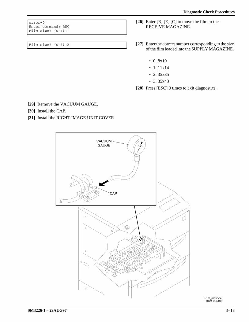
[26] Enter [R] [E] [C] to move the film to theRECEIVE MAGAZINE.
[27] Enter the correct number corresponding to the sizeof the film loaded into the SUPPLY MAGAZINE.
• 0: 8x10
• 1: 11x14
• 2: 35x35
• 3: 35x43
[28] Press [ESC] 3 times to exit diagnostics.
[29] Remove the VACUUM GAUGE.
[30] Install the CAP.
[31] Install the RIGHT IMAGE UNIT COVER.
error=0Enter command: RECFilm size? (0-3):
Film size? (0-3):X
H129_0103DCH129_0103DCA
CAP
GAUGEVACUUM

SERVICE MANUAL
3–14 29AUG97 – SM3226-1
Operation Adjustments
SM3226-1 – 29AUG97 4–1
Section 4: Operation Adjustments
Description Page
Table of Contents
Calibration . . . . . . . . . . . . . . . . . . . . . . . . . . . . . . . . . . . . . . . . . . . . . . . . . . . . . . 4-2 Overview . . . . . . . . . . . . . . . . . . . . . . . . . . . . . . . . . . . . . . . . . . . . . . . . . . . 4-2
When to Calibrate . . . . . . . . . . . . . . . . . . . . . . . . . . . . . . . . . . . . . . . . . . . . 4-3 Calibrating the Printer . . . . . . . . . . . . . . . . . . . . . . . . . . . . . . . . . . . . . . . . 4-4 Measuring and Entering Density Data . . . . . . . . . . . . . . . . . . . . . . . . . . . . 4-6 Using a Stand-alone DENSITOMETER . . . . . . . . . . . . . . . . . . . . . . 4-6 Calibration Errors . . . . . . . . . . . . . . . . . . . . . . . . . . . . . . . . . . . . . . . . 4-7 Using the Kodak Process Control DENSITOMETER as a
Stand-alone DENSITOMETER . . . . . . . . . . . . . . . . . . . . . . . . 4-9 Checking Stored Calibration Settings . . . . . . . . . . . . . . . . . . . . . . . . 4-11Recovering from a Calibration Error . . . . . . . . . . . . . . . . . . . . . . . . . . . . . . . . . 4-12Tone Scaling . . . . . . . . . . . . . . . . . . . . . . . . . . . . . . . . . . . . . . . . . . . . . . . . . . . . 4-13Checking Film Transport . . . . . . . . . . . . . . . . . . . . . . . . . . . . . . . . . . . . . . . . . . 4-14Setting Film Density - Beam Splitter Pulse Settings . . . . . . . . . . . . . . . . . . . . . 4-16Printing a Flat Field Image . . . . . . . . . . . . . . . . . . . . . . . . . . . . . . . . . . . . . . . . . 4-21CES Hidden Mode Setup Procedure . . . . . . . . . . . . . . . . . . . . . . . . . . . . . . . . . 4-22Adjustment of the Right and Left Film Guides . . . . . . . . . . . . . . . . . . . . . . . . . 4-24

SERVICE MANUAL
4–2 29AUG97 – SM3226-1
CalibrationOverviewCalibration is a method of ensuring consistent image appearance despite differences in film emulsions and variationsin the chemistry for the processor. Calibration also provides consistent filmed images regardless of which PRINTERor processor is used.
The LASER PRINTER can store 11 calibration settings. When the PRINTER is taken off-line, the CONTROLPANEL displays the calibration number of the previous calibration.
The user calibrates at any time and stores and prints images during calibration. If the user calibrates while theLASER PRINTER is printing, the new calibration takes effect only when all copies of the current page are printed.
Operation Adjustments
SM3226-1 – 29AUG97 4–3
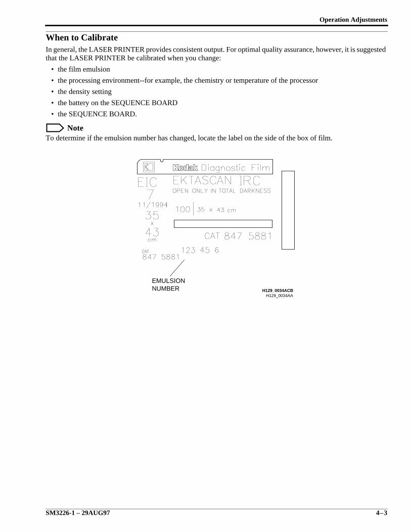
When to CalibrateIn general, the LASER PRINTER provides consistent output. For optimal quality assurance, however, it is suggestedthat the LASER PRINTER be calibrated when you change:
• the film emulsion
• the processing environment--for example, the chemistry or temperature of the processor
• the density setting
• the battery on the SEQUENCE BOARD
• the SEQUENCE BOARD.
NoteTo determine if the emulsion number has changed, locate the label on the side of the box of film.
H129_0034AAH129_0034ACB
EMULSIONNUMBER
SERVICE MANUAL
4–4 29AUG97 – SM3226-1
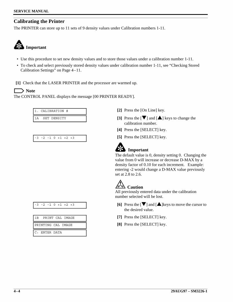
Calibrating the PrinterThe PRINTER can store up to 11 sets of 9 density values under Calibration numbers 1-11.
Important
• Use this procedure to set new density values and to store those values under a calibration number 1-11.
• To check and select previously stored density values under calibration number 1-11, see “Checking StoredCalibration Settings” on Page 4–11.
[1] Check that the LASER PRINTER and the processor are warmed up.
NoteThe CONTROL PANEL displays the message [00 PRINTER READY].
[2] Press the [On Line] key.
[3] Press the [] and [] keys to change thecalibration number.
[4] Press the [SELECT] key.
[5] Press the [SELECT] key.
ImportantThe default value is 0, density setting 0. Changing thevalue from 0 will increase or decrease D-MAX by adensity factor of 0.10 for each increment. Example:entering -2 would change a D-MAX value previouslyset at 2.8 to 2.6.
CautionAll previously entered data under the calibrationnumber selected will be lost.
[6] Press the [] and []keys to move the cursor tothe desired value.
[7] Press the [SELECT] key.
[8] Press the [SELECT] key.
1. CALIBRATION #
1A SET DENSITY
-3 -2 -1 0 +1 +2 +3
-3 -2 -1 0 +1 +2 +3
1B PRINT CAL IMAGE
PRINTING CAL IMAGE
C: ENTER DATA
Operation Adjustments
SM3226-1 – 29AUG97 4–5
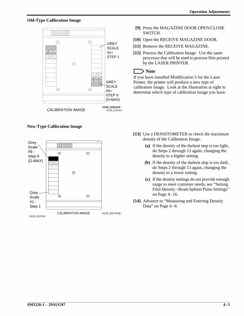
Old-Type Calibration Image
[9] Press the MAGAZINE DOOR OPEN/CLOSESWITCH.
[10] Open the RECEIVE MAGAZINE DOOR.
[11] Remove the RECEIVE MAGAZINE.
[12] Process the Calibration Image. Use the sameprocessor that will be used to process film printedby the LASER PRINTER.
NoteIf you have installed Modification 5 for the LaserPrinter, the printer will produce a new type ofcalibration image. Look at the illustration at right todetermine which type of calibration image you have.
New-Type Calibration Image
[13] Use a DENSITOMETER to check the maximumdensity of the Calibration Image.
(a) If the density of the darkest step is too light,do Steps 2 through 13 again, changing thedensity to a higher setting.
(b) If the density of the darkest step is too dark,do Steps 2 through 13 again, changing thedensity to a lower setting.
(c) If the density settings do not provide enoughrange to meet customer needs, see “SettingFilm Density - Beam Splitter Pulse Settings”on Page 4–16.
[14] Advance to “Measuring and Entering DensityData” on Page 4–6.
H129_0101AACALIBRATION IMAGEH129_0101ACF
GREYSCALE#1=STEP 1
GREYSCALE#9=STEP 9(D-MAX)
CALIBRATION IMAGEH129_0107AC
Step 1#1 -ScaleGrey
(D-MAX)Step 9#9 -ScaleGrey
H129_0107ACB
SERVICE MANUAL
4–6 29AUG97 – SM3226-1
Measuring and Entering Density Data
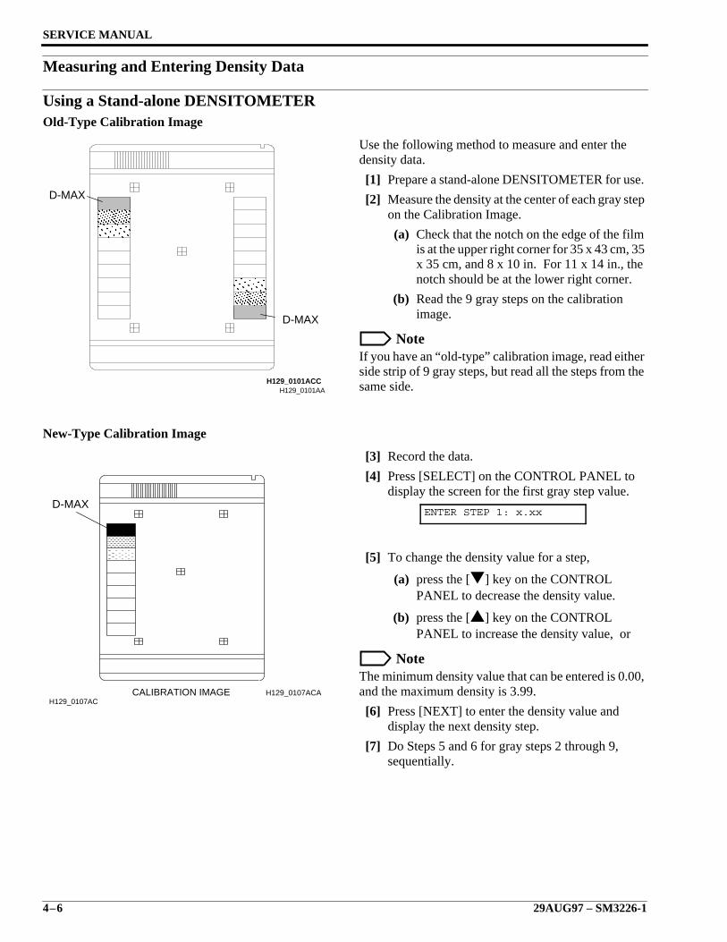
Using a Stand-alone DENSITOMETEROld-Type Calibration Image
Use the following method to measure and enter thedensity data.
[1] Prepare a stand-alone DENSITOMETER for use.
[2] Measure the density at the center of each gray stepon the Calibration Image.
(a) Check that the notch on the edge of the filmis at the upper right corner for 35 x 43 cm, 35x 35 cm, and 8 x 10 in. For 11 x 14 in., thenotch should be at the lower right corner.
(b) Read the 9 gray steps on the calibrationimage.
NoteIf you have an “old-type” calibration image, read eitherside strip of 9 gray steps, but read all the steps from thesame side.
New-Type Calibration Image
[3] Record the data.
[4] Press [SELECT] on the CONTROL PANEL todisplay the screen for the first gray step value.
[5] To change the density value for a step,
(a) press the [] key on the CONTROLPANEL to decrease the density value.
(b) press the [] key on the CONTROLPANEL to increase the density value, or
NoteThe minimum density value that can be entered is 0.00,and the maximum density is 3.99.
[6] Press [NEXT] to enter the density value anddisplay the next density step.
[7] Do Steps 5 and 6 for gray steps 2 through 9,sequentially.
ENTER STEP 1: x.xx
H129_0101AAH129_0101ACC
D-MAX
D-MAX
CALIBRATION IMAGEH129_0107AC
D-MAX
H129_0107ACA
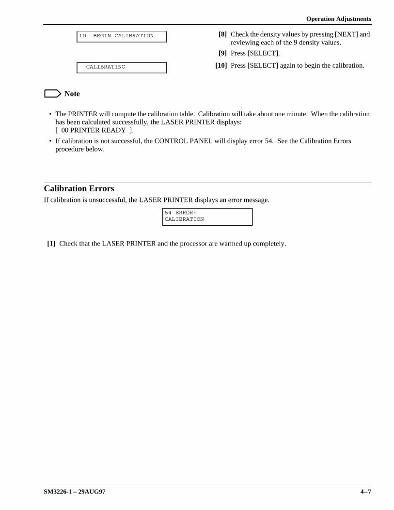
Operation Adjustments
SM3226-1 – 29AUG97 4–7
[8] Check the density values by pressing [NEXT] andreviewing each of the 9 density values.
[9] Press [SELECT].
[10] Press [SELECT] again to begin the calibration.
Note
• The PRINTER will compute the calibration table. Calibration will take about one minute. When the calibrationhas been calculated successfully, the LASER PRINTER displays:[ 00 PRINTER READY ].
• If calibration is not successful, the CONTROL PANEL will display error 54. See the Calibration Errorsprocedure below.
Calibration ErrorsIf calibration is unsuccessful, the LASER PRINTER displays an error message.
[1] Check that the LASER PRINTER and the processor are warmed up completely.
1D BEGIN CALIBRATION
CALIBRATING
54 ERROR:CALIBRATION
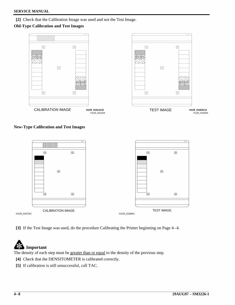
SERVICE MANUAL
4–8 29AUG97 – SM3226-1
[2] Check that the Calibration Image was used and not the Test Image.
Old-Type Calibration and Test Images
New-Type Calibration and Test Images
[3] If the Test Image was used, do the procedure Calibrating the Printer beginning on Page 4–4.
ImportantThe density of each step must be greater than or equal to the density of the previous step.
[4] Check that the DENSITOMETER is calibrated correctly.
[5] If calibration is still unsuccessful, call TAC.
H129_0101AACALIBRATION IMAGE H129_0101ACD
H129_0100AATEST IMAGE H129_0100ACA
CALIBRATION IMAGEH129_0107AC
TEST IMAGEH129_0108AC

Operation Adjustments
SM3226-1 – 29AUG97 4–9
Using the Kodak Process Control DENSITOMETER as a Stand-alone DENSITOMETER
The Kodak PROCESS CONTROL DENSITOMETERcan also be used to read the 9 density values. To do so,use the following procedure:
[1] Prepare the DENSITOMETER for use.
[2] After passing the self-test, the DENSITOMETERwill display:
[3] Simultaneously press [MENU] and [MENU].
[4] Position the film tightly up to the Stop of theDENSITOMETER, then insert the film until itrests against the drive rollers and the motor isactivated.
NoteAlways read the densities with the emulsion side of thefilm facing up. The notch should be in the upper righthand corner.
[5] While the film is measured, hold the film againstthe Stop, guiding the film to prevent skewing.
[6] Press the right-side [MENU] key that is under thedisplayed word “go”.
[7] Press the right-side [MENU] key again when theDENSITOMETER displays “go”.
CH:I (lab identifier) CH:I go

SERVICE MANUAL
4–10 29AUG97 – SM3226-1
[8] Press the left-side [CHAN] key under the “P1”three times when the DENSITOMETER displaysthe screen at the right, with a “P1” at the bottomleft corner.
NoteThe third time the [CHAN] key is pressed, theDENSITOMETER will display:
ImportantThe DENSITOMETER is ready to display the densitiesfor all 21 steps that it has read from the CalibrationImage. The Kodak Ektascan 1120 LASER PRINTERuses only the densities of steps 7 through 15. To readand record the required densities:
[9] Press the right-side [CHAN] key and scrollthrough the densities.
[10] Record the values when of density steps 7 through15.
[11] Check the values by scrolling through densitysteps 7 through 15 again.
[12] Simultaneously press [MENU] and [MENU].
NoteThe PORTABLE COMPUTER will display the MainMenu.
[13] Enter the values as described in the procedure“Using a Stand-alone DENSITOMETER”beginning in Step 4 on Page 4–6.
CH:I SD.Indx = x.xx P1 CIndx = x.xx
CH:I Temp F = xx.x P4 Den #01 = x.xx
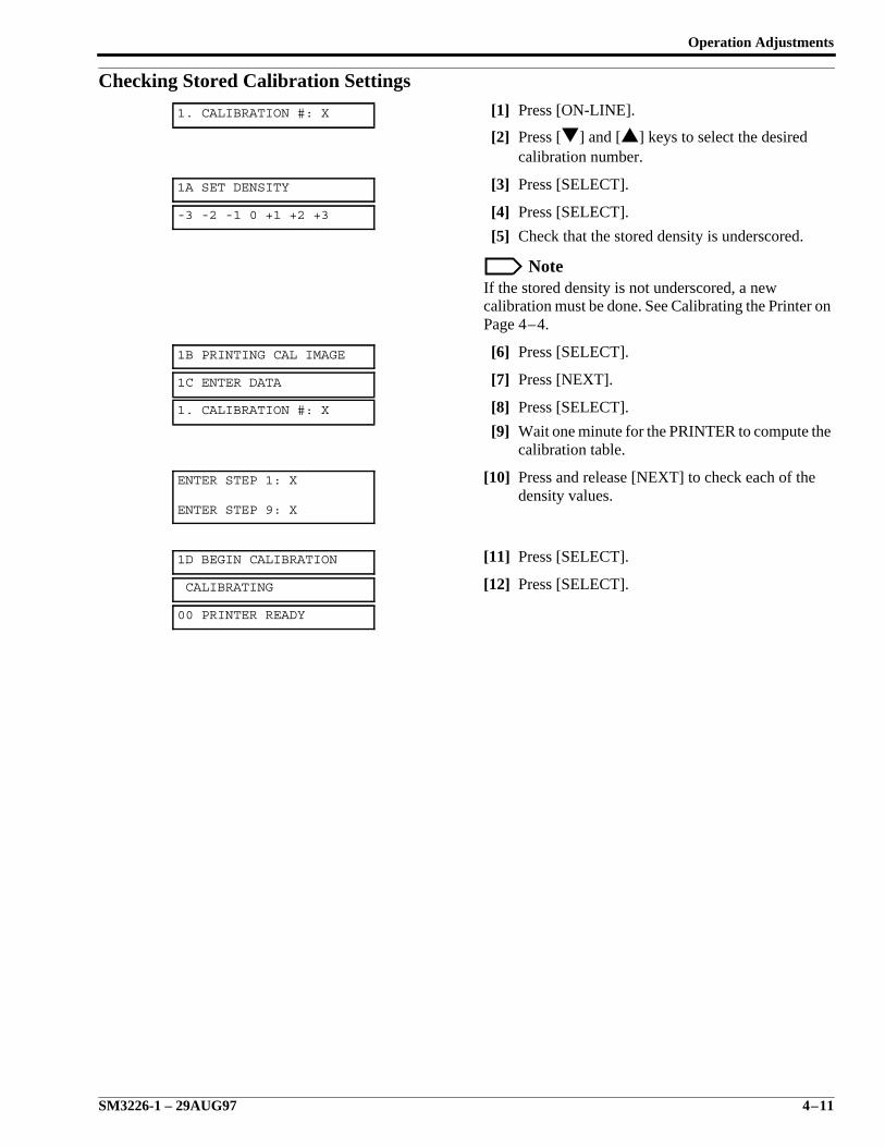
Operation Adjustments
SM3226-1 – 29AUG97 4–11
Checking Stored Calibration Settings[1] Press [ON-LINE].
[2] Press [] and [] keys to select the desiredcalibration number.
[3] Press [SELECT].
[4] Press [SELECT].
[5] Check that the stored density is underscored.
NoteIf the stored density is not underscored, a newcalibration must be done. See Calibrating the Printer onPage 4–4.
[6] Press [SELECT].
[7] Press [NEXT].
[8] Press [SELECT].
[9] Wait one minute for the PRINTER to compute thecalibration table.
[10] Press and release [NEXT] to check each of thedensity values.
[11] Press [SELECT].
[12] Press [SELECT].
1. CALIBRATION #: X
1A SET DENSITY
-3 -2 -1 0 +1 +2 +3
1B PRINTING CAL IMAGE
1C ENTER DATA
1. CALIBRATION #: X
ENTER STEP 1: X
ENTER STEP 9: X
1D BEGIN CALIBRATION
CALIBRATING
00 PRINTER READY
SERVICE MANUAL
4–12 29AUG97 – SM3226-1
Recovering from a Calibration ErrorPerform this procedure if you receive a calibration error when energizing the 1120 Laser Printer.
ImportantWhen the printer displays “54 ERROR:CALIBRATION,” you must perform this procedure before you can enter off-line mode to calibrate the printer.
[1] Enter CES Hidden Mode.
[2] Press [Next] to step through the options until “RAW DATA x:y.yy” is displayed.
[3] Enter the following 9 raw data values:
1. 0.15
2. 0.22
3. 0.42
4. 0.79
5. 1.25
6. 1.73
7. 2.12
8. 2.46
9. 2.71
[4] Press [Next] until “CAL DATA: xxxx” is displayed.
NoteAt this point, you can set CAL DATA to either “NORMAL” or “OK”.
Setting CAL DATA to “NORMAL” Setting CAL DATA to “OK”
1. Set CAL DATA to “NORMAL”.
2. Exit from CES HIDDEN MODE.
The printer displays “09 CALIBRATEPRINTER”.
3. Enter off-line mode.
4. Calibrate the printer.
NoteAfter calibrating, the value for CAL DATA inHIDDEN MODE changes to “OK”.
1. Set CAL DATA to “OK”.
2. Exit from CES HIDDEN MODE.
NoteThe printer displays “07 PRINTER WARM UP”
ImportantWhen you set CAL DATA to “OK”, the printercalibrates itself. You can continue to use the printer,but you should enter off-line mode and perform amanual calibration as soon as possible to ensuremaximum image quality.
Operation Adjustments
SM3226-1 – 29AUG97 4–13
Tone Scaling
Important
• Before doing a Tone Scale adjustment, check that the Imaging Device Monitor has been correctly adjusted. ThisMonitor adjustment should not be changed once the Tone Scaling has been completed.
• Tone Scale adjustments should only be done by trained personnel.
Tone Scaling is a technique of making printed images match the images on the input monitor. To adjust the tonescale, use the following procedure:
[1] Check that the Density is set for the desired maximum density using the Setup Procedure beginning onPage 4–22.
[2] Calibrate the PRINTER using the Calibration Procedure on Page 4–4.
[3] Use the Keypad [Program] key to adjust the Curve Shape. If necessary, see the User Manual, 5B9622.
[4] Use the Keypad [Program] key to adjust the Contrast. If necessary, see the User Manual, 5B9622.
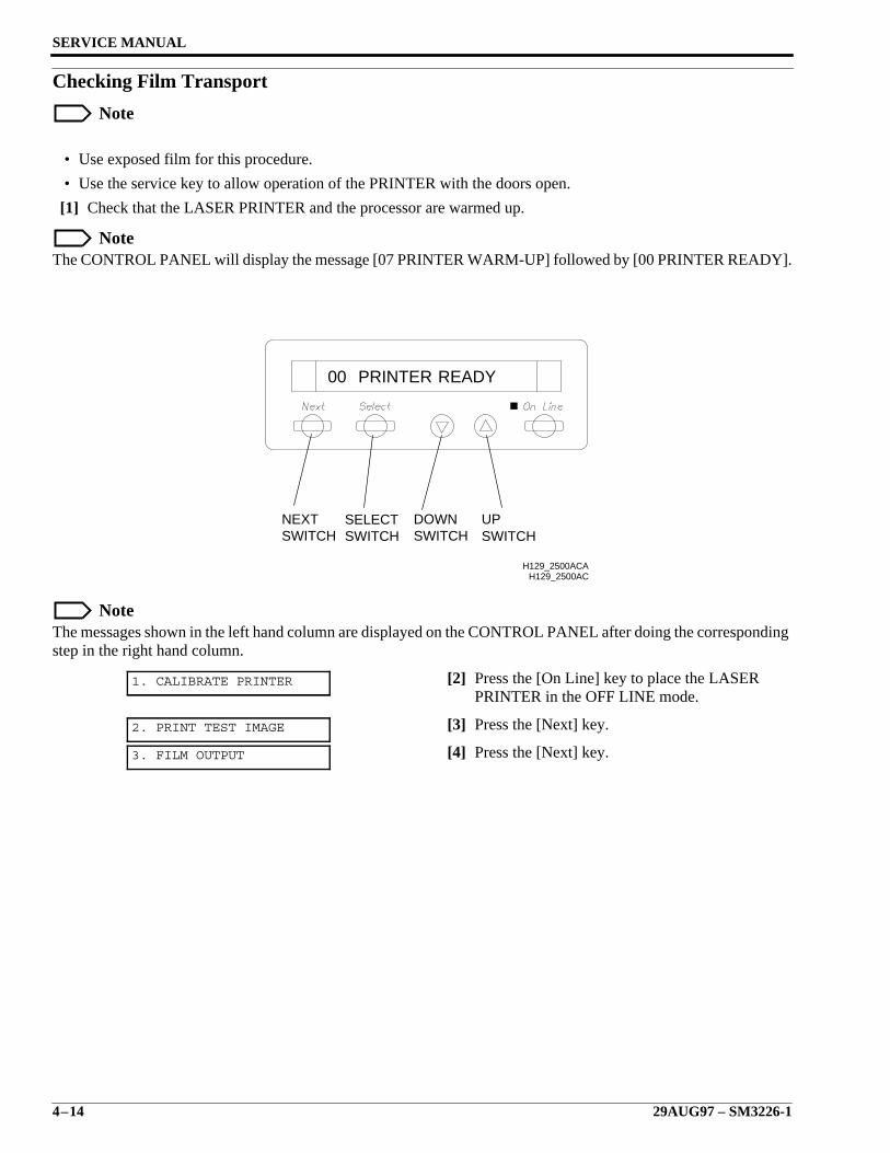
SERVICE MANUAL
4–14 29AUG97 – SM3226-1
Checking Film Transport
Note
• Use exposed film for this procedure.
• Use the service key to allow operation of the PRINTER with the doors open.
[1] Check that the LASER PRINTER and the processor are warmed up.
NoteThe CONTROL PANEL will display the message [07 PRINTER WARM-UP] followed by [00 PRINTER READY].
NoteThe messages shown in the left hand column are displayed on the CONTROL PANEL after doing the correspondingstep in the right hand column.
[2] Press the [On Line] key to place the LASERPRINTER in the OFF LINE mode.
[3] Press the [Next] key.
[4] Press the [Next] key.
1. CALIBRATE PRINTER
2. PRINT TEST IMAGE
3. FILM OUTPUT
H129_2500AC
READYPRINTER00
NEXTSWITCH
SELECTSWITCH
DOWNSWITCH
UPSWITCH
H129_2500ACA
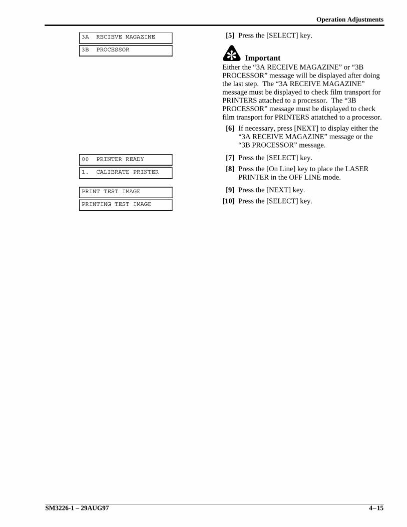
Operation Adjustments
SM3226-1 – 29AUG97 4–15
[5] Press the [SELECT] key.
ImportantEither the “3A RECEIVE MAGAZINE” or “3BPROCESSOR” message will be displayed after doingthe last step. The “3A RECEIVE MAGAZINE”message must be displayed to check film transport forPRINTERS attached to a processor. The “3BPROCESSOR” message must be displayed to checkfilm transport for PRINTERS attatched to a processor.
[6] If necessary, press [NEXT] to display either the“3A RECEIVE MAGAZINE” message or the“3B PROCESSOR” message.
[7] Press the [SELECT] key.
[8] Press the [On Line] key to place the LASERPRINTER in the OFF LINE mode.
[9] Press the [NEXT] key.
[10] Press the [SELECT] key.
3A RECIEVE MAGAZINE
3B PROCESSOR
00 PRINTER READY
1. CALIBRATE PRINTER
PRINT TEST IMAGE
PRINTING TEST IMAGE
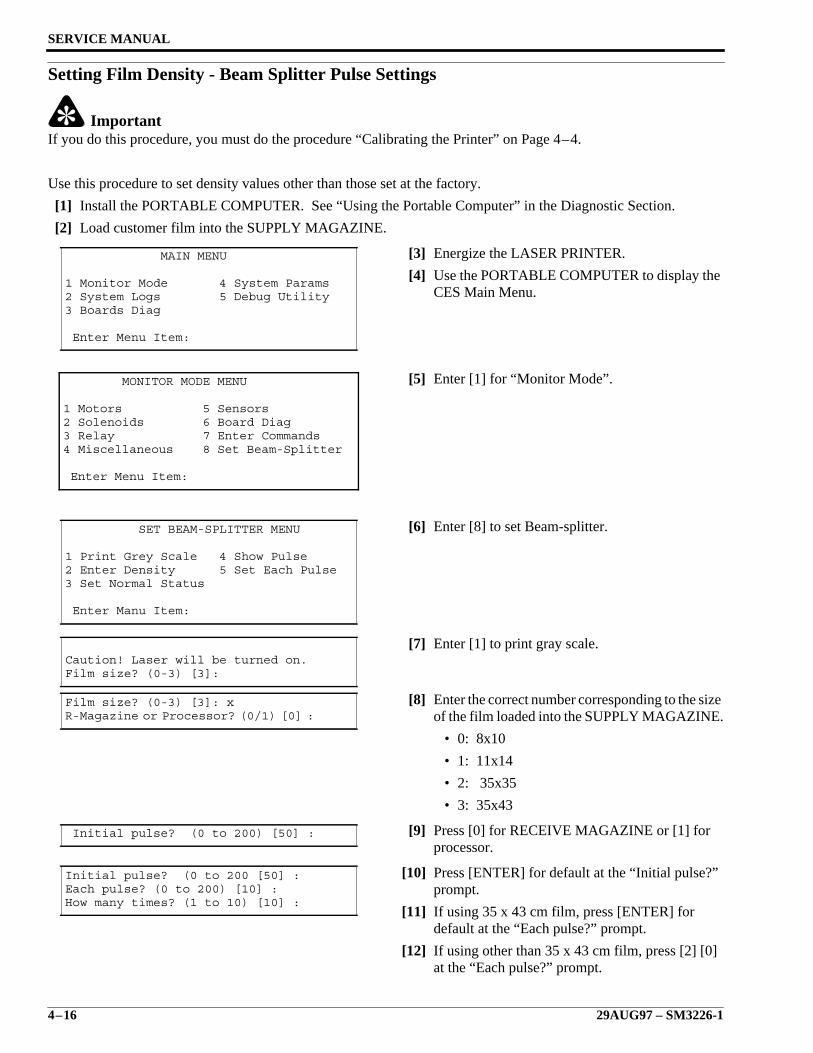
SERVICE MANUAL
4–16 29AUG97 – SM3226-1
Setting Film Density - Beam Splitter Pulse Settings
ImportantIf you do this procedure, you must do the procedure “Calibrating the Printer” on Page 4–4.
Use this procedure to set density values other than those set at the factory.
[1] Install the PORTABLE COMPUTER. See “Using the Portable Computer” in the Diagnostic Section.
[2] Load customer film into the SUPPLY MAGAZINE.
[3] Energize the LASER PRINTER.
[4] Use the PORTABLE COMPUTER to display theCES Main Menu.
[5] Enter [1] for “Monitor Mode”.
[6] Enter [8] to set Beam-splitter.
[7] Enter [1] to print gray scale.
[8] Enter the correct number corresponding to the sizeof the film loaded into the SUPPLY MAGAZINE.
• 0: 8x10
• 1: 11x14
• 2: 35x35
• 3: 35x43
[9] Press [0] for RECEIVE MAGAZINE or [1] forprocessor.
[10] Press [ENTER] for default at the “Initial pulse?”prompt.
[11] If using 35 x 43 cm film, press [ENTER] fordefault at the “Each pulse?” prompt.
[12] If using other than 35 x 43 cm film, press [2] [0]at the “Each pulse?” prompt.
MAIN MENU
1 Monitor Mode 4 System Params2 System Logs 5 Debug Utility3 Boards Diag
Enter Menu Item:
MONITOR MODE MENU
1 Motors 5 Sensors2 Solenoids 6 Board Diag3 Relay 7 Enter Commands4 Miscellaneous 8 Set Beam-Splitter
Enter Menu Item:
SET BEAM-SPLITTER MENU
1 Print Grey Scale 4 Show Pulse2 Enter Density 5 Set Each Pulse3 Set Normal Status
Enter Manu Item:
Caution! Laser will be turned on.Film size? (0-3) [3]:
Film size? (0-3) [3]: xR-Magazine or Processor? (0/1) [0] :
Initial pulse? (0 to 200) [50] :
Initial pulse? (0 to 200 [50] :Each pulse? (0 to 200) [10] :How many times? (1 to 10) [10] :
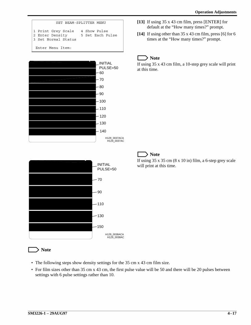
Operation Adjustments
SM3226-1 – 29AUG97 4–17
[13] If using 35 x 43 cm film, press [ENTER] fordefault at the “How many times?” prompt.
[14] If using other than 35 x 43 cm film, press [6] for 6times at the “How many times?” prompt.
NoteIf using 35 x 43 cm film, a 10-step grey scale will printat this time.
NoteIf using 35 x 35 cm (8 x 10 in) film, a 6-step grey scalewill print at this time.
Note
• The following steps show density settings for the 35 cm x 43 cm film size.
• For film sizes other than 35 cm x 43 cm, the first pulse value will be 50 and there will be 20 pulses betweensettings with 6 pulse settings rather than 10.
SET BEAM-SPLITTER MENU
1 Print Grey Scale 4 Show Pulse2 Enter Density 5 Set Each Pulse3 Set Normal Status
Enter Menu Item:
H129_0037ACH129_0037ACA
PULSE=50INITIAL
100
140
130
120
110
90
80
70
60
H129_0038AC
PULSE=50INITIAL
150
130
110
90
70
H129_0038ACA
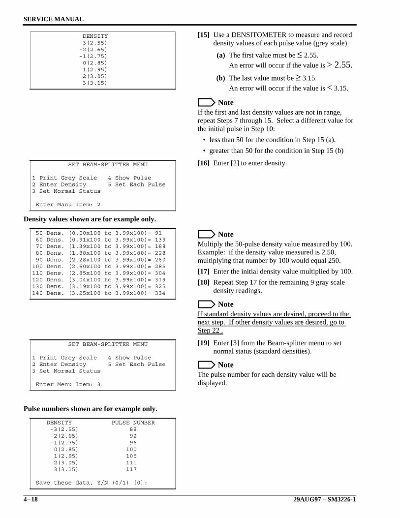
SERVICE MANUAL
4–18 29AUG97 – SM3226-1
[15] Use a DENSITOMETER to measure and recorddensity values of each pulse value (grey scale).
(a) The first value must be ≤ 2.55.
An error will occur if the value is > 2.55.(b) The last value must be ≥ 3.15.
An error will occur if the value is < 3.15.
NoteIf the first and last density values are not in range,repeat Steps 7 through 15. Select a different value forthe initial pulse in Step 10:
• less than 50 for the condition in Step 15 (a).
• greater than 50 for the condition in Step 15 (b)
[16] Enter [2] to enter density.
Density values shown are for example only.
NoteMultiply the 50-pulse density value measured by 100.Example: if the density value measured is 2.50,multiplying that number by 100 would equal 250.
[17] Enter the initial density value multiplied by 100.
[18] Repeat Step 17 for the remaining 9 gray scaledensity readings.
NoteIf standard density values are desired, proceed to thenext step. If other density values are desired, go toStep 22 .
[19] Enter [3] from the Beam-splitter menu to setnormal status (standard densities).
NoteThe pulse number for each density value will bedisplayed.
Pulse numbers shown are for example only.
DENSITY -3(2.55) -2(2.65) -1(2.75) 0(2.85) 1(2.95) 2(3.05) 3(3.15)
SET BEAM-SPLITTER MENU
1 Print Grey Scale 4 Show Pulse2 Enter Density 5 Set Each Pulse3 Set Normal Status
Enter Manu Item: 2
50 Dens. (0.00x100 to 3.99x100)= 91 60 Dens. (0.91x100 to 3.99x100)= 139 70 Dens. (1.39x100 to 3.99x100)= 188 80 Dens. (1.88x100 to 3.99x100)= 228 90 Dens. (2.28x100 to 3.99x100)= 260100 Dens. (2.60x100 to 3.99x100)= 285110 Dens. (2.85x100 to 3.99x100)= 304120 Dens. (3.04x100 to 3.99x100)= 319130 Dens. (3.19x100 to 3.99x100)= 325140 Dens. (3.25x100 to 3.99x100)= 334
SET BEAM-SPLITTER MENU
1 Print Grey Scale 4 Show Pulse2 Enter Density 5 Set Each Pulse3 Set Normal Status
Enter Menu Item: 3
DENSITY PULSE NUMBER -3(2.55) 88 -2(2.65) 92 -1(2.75) 96 0(2.85) 100 1(2.95) 105 2(3.05) 111 3(3.15) 117
Save these data, Y/N (0/1) [0]:
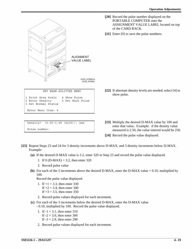
Operation Adjustments
SM3226-1 – 29AUG97 4–19
[20] Record the pulse number displayed on thePORTABLE COMPUTER onto theASSIGNMENT VALUE LABEL located on topof the CARD RACK.
[21] Enter [0] to save the pulse numbers.
[22] If alternate density levels are needed, select [4] toshow pulse.
[23] Multiply the desired D-MAX value by 100 andenter that value, Example: if the density valuemeasured is 2.50, the value entered would be 250.
[24] Record the pulse value displayed.
[25] Repeat Steps 23 and 24 for 3 density increments above D-MAX, and 3 density increments below D-MAX.Example:
(a) If the desired D-MAX value is 3.2, enter 320 in Step 23 and record the pulse value displayed.
1. If 0 (D-MAX) = 3.2, then enter 320
2. Record pulse value
(b) For each of the 3 increments above the desired D-MAX, enter the D-MAX value + 0.10, multiplied by100.Record the pulse value displayed.
1. If +1 = 3.3, then enter 330If +2 = 3.4, then enter 340If +3 = 3.5, then enter 350
2. Record pulse values displayed for each increment.
(c) For each of the 3 increments below the desired D-MAX, enter the D-MAX value- 0.10, multiplied by 100. Record the pulse value displayed.
1. If -1 = 3.1, then enter 310If -2 = 3.0, then enter 300If -3 = 2.9, then enter 290
2. Record pulse values displayed for each increment.
SET BEAM-SPLITTER MENU
1 Print Grey Scale 4 Show Pulse2 Enter Density 5 Set Each Pulse3 Set Normal Status
Enter Menu Item: 4
Density? (0.00-3.99 (x100)): xxx
Pulse number:
H129_0709AC
VALUE LABELALIGNMENT
H129_0709ACA
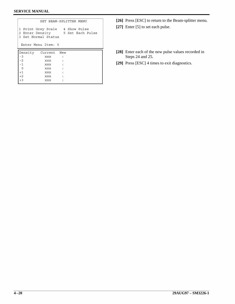
SERVICE MANUAL
4–20 29AUG97 – SM3226-1
[26] Press [ESC] to return to the Beam-splitter menu.
[27] Enter [5] to set each pulse.
[28] Enter each of the new pulse values recorded inSteps 24 and 25.
[29] Press [ESC] 4 times to exit diagnostics.
SET BEAM-SPLITTER MENU
1 Print Grey Scale 4 Show Pulse2 Enter Density 5 Set Each Pulse3 Set Normal Status
Enter Menu Item: 5
Density Current New-3 xxx :-2 xxx :-1 xxx : 0 xxx :+1 xxx :+2 xxx :+3 xxx :
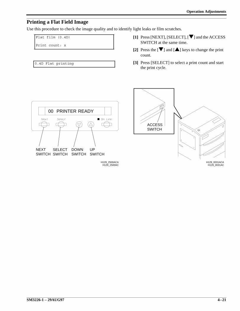
Operation Adjustments
SM3226-1 – 29AUG97 4–21
Printing a Flat Field ImageUse this procedure to check the image quality and to identify light leaks or film scratches.
[1] Press [NEXT], [SELECT], [] and the ACCESSSWITCH at the same time.
[2] Press the [] and [] keys to change the printcount.
[3] Press [SELECT] to select a print count and startthe print cycle.
Flat film (0.4D)
Print count: x
0.4D Flat printing
H129_2500AC
READYPRINTER00
NEXTSWITCH
SELECTSWITCH
DOWNSWITCH
UPSWITCH
H129_2500ACAH129_0031AC
H129_0031ACA
SWITCHACCESS
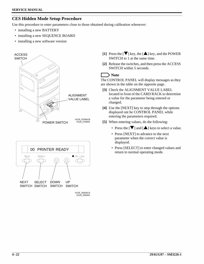
SERVICE MANUAL
4–22 29AUG97 – SM3226-1
CES Hidden Mode Setup ProcedureUse this procedure to enter parameters close to those obtained during calibration whenever:
• installing a new BATTERY
• installing a new SEQUENCE BOARD
• installing a new software version
[1] Press the [] key, the [] key, and the POWERSWITCH to 1 at the same time.
[2] Release the switches, and then press the ACCESSSWITCH within 5 seconds.
NoteThe CONTROL PANEL will display messages as theyare shown in the table on the opposite page.
[3] Check the ALIGNMENT VALUE LABELlocated in front of the CARD RACK to determinea value for the parameter being entered orchanged.
[4] Use the [NEXT] key to step through the optionsdisplayed ont he CONTROL PANEL whileentering the parameters required.
[5] When entering values, do the following:
• Press the [] and [] keys to select a value.
• Press [NEXT] to advance to the nextparameter when the correct value isdisplayed.
• Press [SELECT] to enter changed values andreturn to normal operating mode.
H129_0709AC
VALUE LABELALIGNMENT
ACCESSSWITCH
POWER SWITCHH129_0709ACB
H129_2500AC
READYPRINTER00
NEXTSWITCH
SELECTSWITCH
DOWNSWITCH
UPSWITCH
H129_2500ACA
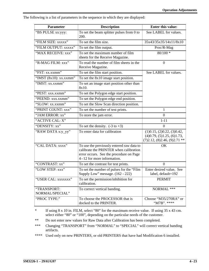
Operation Adjustments
SM3226-1 – 29AUG97 4–23
The following is a list of parameters in the sequence in which they are displayed:
Parameter Description Enter this value:
“BS PULSE xx:yyy: To set the beam splitter pulses from 0 to200.
See LABEL for values.
“FILM SIZE: xxxxx” To set the film size. 35x43/35x35/14x11/8x10
“FILM OUTPUT: xxxxx” To set the film output. Proc/R-Mag
“MAX RECEIVE: xxx” To set the maximum number of filmsheets for the Receive Magazine.
80/100 *
“R-MAG FILM: xxx” To read the number of film sheets in theReceive Magazine.
0
“FST: xx.xxmm” To set the film start position. See LABEL for values.
“IMST (8x10): xx.xxmm” To set the 8x10 image start position.
“IMST: xx.xxmm” To set an image start position other than8x10.
“PEST: xxx.xxmm” To set the Polygon edge start position.
“PEEND: xxx.xxmm” To set the Polygon edge end position.
“SLOW: xx.xxmm” To set the Slow Scan direction position.
“PRINT COUNT: xxx” To set the number of test prints. 1
“JAM ERROR: xx” To store the jam error. 0
“ACTIVE CAL: X” 1-11
“DENSITY: xx” To set the density. (-3 to +3) 0
“RAW DATA x:y_yy” To enter data for calibration (1)0.15, (2)0.22, (3)0.42,(4)0.79, (5)1.25, (6)1.73,
(7)2.12, (8)2.46, (9)2.71 **
“CAL DATA: xxxx” To use the previously entered raw data tocalibrate the PRINTER when calibrationerror occurs. See the procedure on Page4–12 for more information.
OK
“CONTRAST: xx” To set the contrast for test prints. 0
“LOW STEP: xxx” To set the number of pulses for the “FilmSupply Low” message. (162 - 222)
Enter desired value, Seelabel, default=192
“USER CAL: xxxxxxx” To set the permission/inhibition forcalibration.
PERMIT
“TRANSPORT:NORMAL/SPECIAL”
To correct vertical banding. NORMAL ***
“PROC TYPE:” To choose the PROCESSOR that isdocked to the PRINTER.
Choose “M35/270RA” or“M7B”. ****
* If using 8 x 10 in. FILM, select “80” for the maximum receive value. If using 35 x 43 cm.select either “80” or “100”, depending on the particular needs of the customer.
** Do not enter new values for Raw Data after Calibration has been completed.
*** Changing “TRANSPORT” from “NORMAL” to “SPECIAL” will correct vertical bandingartifacts.
**** Used only on new PRINTERS, or old PRINTERS that have had Modification 6 installed.
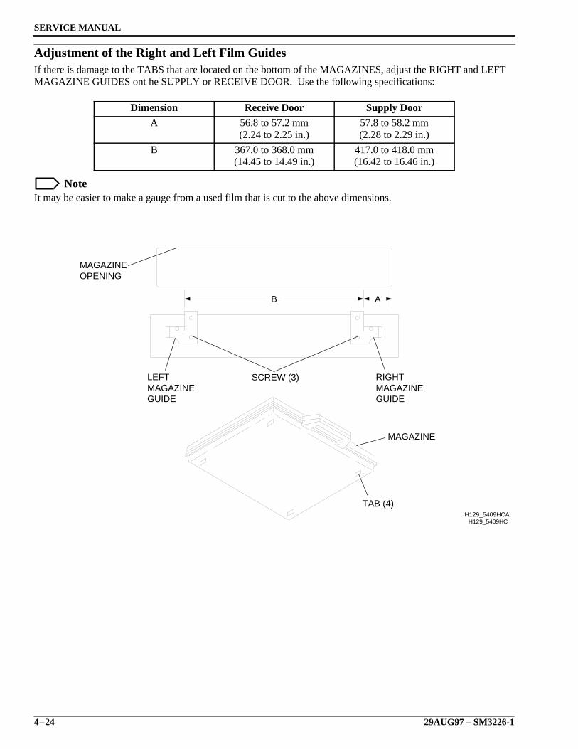
SERVICE MANUAL
4–24 29AUG97 – SM3226-1
Adjustment of the Right and Left Film GuidesIf there is damage to the TABS that are located on the bottom of the MAGAZINES, adjust the RIGHT and LEFTMAGAZINE GUIDES ont he SUPPLY or RECEIVE DOOR. Use the following specifications:
NoteIt may be easier to make a gauge from a used film that is cut to the above dimensions.
Dimension Receive Door Supply Door
A 56.8 to 57.2 mm(2.24 to 2.25 in.)
57.8 to 58.2 mm(2.28 to 2.29 in.)
B 367.0 to 368.0 mm(14.45 to 14.49 in.)
417.0 to 418.0 mm(16.42 to 16.46 in.)
H129_5409HC
B A
SCREW (3)
GUIDEMAGAZINELEFT
MAGAZINEOPENING
MAGAZINE
TAB (4)
GUIDEMAGAZINERIGHT
H129_5409HCA
Electrical Adjustments
SM3226-1 – 29AUG97 5–1
Section 5: Electrical Adjustments
Description Page
Table of Contents
Circuit Boards . . . . . . . . . . . . . . . . . . . . . . . . . . . . . . . . . . . . . . . . . . . . . . . . . . . . . . . 5-2 Driver Board - Versions 1, 2, & 3 and Serial No. Range 500025-500389 . . . . . 5-2
DC/DC Converter Output Voltage . . . . . . . . . . . . . . . . . . . . . . . . . . . . . . . 5-2 Clock Frequency for Electromagnetic Pump . . . . . . . . . . . . . . . . . . . . . . . 5-4 Film Sensor Adjustments . . . . . . . . . . . . . . . . . . . . . . . . . . . . . . . . . . . . . . 5-6
Emitter Intensity of Film Sensors IL1, IL2, and IL3. . . . . . . . . . . . . . . . . . 5-7 Output Voltage for Receivers PT1, PT2, and PT3 . . . . . . . . . . . . . . . . . . . 5-9
Temporary Emitter Pulse Cycle . . . . . . . . . . . . . . . . . . . . . . . . . . . . . . . . . 5-13No Film Signal Holding Time. . . . . . . . . . . . . . . . . . . . . . . . . . . . . . . . . . . 5-15Permanent Emitter Pulse Cycle . . . . . . . . . . . . . . . . . . . . . . . . . . . . . . . . . . 5-17Emitter Pulse Duty Ratio for IL1, IL2, and IL3 . . . . . . . . . . . . . . . . . . . . . 5-19
Driver Board - Versions 4, 5, 6 & Universal and Serial No. Range 500390-500898,600133-600306 . . . . . . . . . . . . . . . . . . . . . . . . . . . . . . . . . . . . . . . . . . . . . . . . 5-21
DC/DC Converter Output Voltage . . . . . . . . . . . . . . . . . . . . . . . . . . . . . . . 5-21 Clock Frequency for Electromagnetic Pump . . . . . . . . . . . . . . . . . . . . . . . 5-22 Film Sensor Adjustments . . . . . . . . . . . . . . . . . . . . . . . . . . . . . . . . . . . . . . 5-24 Emitter Intensity of Film Sensors IL1, IL2, and IL3 . . . . . . . . . . . . . . . . . 5-25 Output Voltage for Receivers PT1, PT2, and PT3 . . . . . . . . . . . . . . . . . . . 5-27 No Film Signal Holding Time . . . . . . . . . . . . . . . . . . . . . . . . . . . . . . . . . . 5-31 Permanent Emitter Pulse Cycle . . . . . . . . . . . . . . . . . . . . . . . . . . . . . . . . . 5-35 Emitter Pulse Duty Ratio for Sensors IL1, IL2, and IL3 . . . . . . . . . . . . . . 5-38Driver Board - Versions 6 & Higher and Serial No. Range 500899-present, 600307-
present . . . . . . . . . . . . . . . . . . . . . . . . . . . . . . . . . . . . . . . . . . . . . . . . . . . . . . 5-41 DC/DC Converter Output Voltage . . . . . . . . . . . . . . . . . . . . . . . . . . . . . . . 5-41 Film Sensor Adjustments . . . . . . . . . . . . . . . . . . . . . . . . . . . . . . . . . . . . . . 5-42 Output Voltage for Receivers PT1, PT2, and PT3 . . . . . . . . . . . . . . . . . . . 5-43 Emitter Pulse Duty Ratio for Sensors IL1, IL2, and IL3 . . . . . . . . . . . . . . 5-47Sequence Board . . . . . . . . . . . . . . . . . . . . . . . . . . . . . . . . . . . . . . . . . . . . . . . . . 5-48 Beam Detector Signal Offset Voltage . . . . . . . . . . . . . . . . . . . . . . . . . . . . 5-485-Phase Pulse Motor Boards for the Transport Motor Voltages (5PMD) . . . . . 5-522-Phase Pulse Motor Board (2PMD), Slide Base Motor Voltage . . . . . . . . . . . 5-57Laser Diode Control Board . . . . . . . . . . . . . . . . . . . . . . . . . . . . . . . . . . . . . . . . 5-60 Setting Laser Diode Control for D-Min . . . . . . . . . . . . . . . . . . . . . . . . . . . 5-60 Fluctuation of the Laser Diode Reference Current . . . . . . . . . . . . . . . . . . . 5-64Control Panel Board . . . . . . . . . . . . . . . . . . . . . . . . . . . . . . . . . . . . . . . . . . . . . . 5-68
Sensors. . . . . . . . . . . . . . . . . . . . . . . . . . . . . . . . . . . . . . . . . . . . . . . . . . . . . . . . . . . . . 5-70 Sucker Pad Height . . . . . . . . . . . . . . . . . . . . . . . . . . . . . . . . . . . . . . . . . . . . . . . . 5-70
PHF Film Suction Sensor . . . . . . . . . . . . . . . . . . . . . . . . . . . . . . . . . . . . . . . . . . 5-74PHS1 S Magazine Open Sensor . . . . . . . . . . . . . . . . . . . . . . . . . . . . . . . . . . . . . 5-76PHS2 S Magazine Close Sensor . . . . . . . . . . . . . . . . . . . . . . . . . . . . . . . . . . . . . 5-78PH3 S Magazine Door Sensor . . . . . . . . . . . . . . . . . . . . . . . . . . . . . . . . . . . . . . 5-80CHS1 Slide Base Position Sensor Reference Position . . . . . . . . . . . . . . . . . . . . 5-81PHR1 R Magazine Open Sensor . . . . . . . . . . . . . . . . . . . . . . . . . . . . . . . . . . . . 5-86PHR2 R Magazine Close Sensor . . . . . . . . . . . . . . . . . . . . . . . . . . . . . . . . . . . . 5-88PH4 R Magazine Door Sensor . . . . . . . . . . . . . . . . . . . . . . . . . . . . . . . . . . . . . . 5-90Receive Side Stopper Position . . . . . . . . . . . . . . . . . . . . . . . . . . . . . . . . . . . . . . 5-91CHT1 Supply Roller Position Sensor . . . . . . . . . . . . . . . . . . . . . . . . . . . . . . . . . 5-93CHT2 Receive Roller Position Sensor . . . . . . . . . . . . . . . . . . . . . . . . . . . . . . . . 5-97
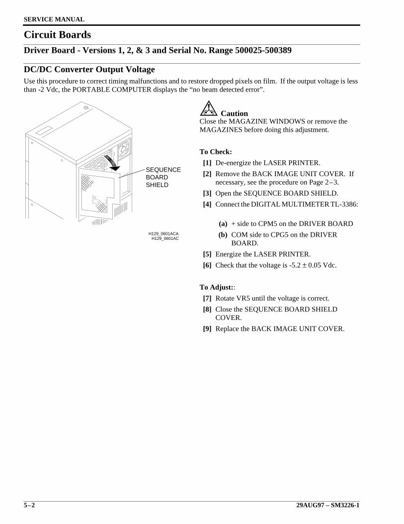
SERVICE MANUAL
5–2 29AUG97 – SM3226-1
Circuit BoardsDriver Board - Versions 1, 2, & 3 and Serial No. Range 500025-500389
DC/DC Converter Output VoltageUse this procedure to correct timing malfunctions and to restore dropped pixels on film. If the output voltage is lessthan -2 Vdc, the PORTABLE COMPUTER displays the “no beam detected error”.
CautionClose the MAGAZINE WINDOWS or remove theMAGAZINES before doing this adjustment.
To Check:
[1] De-energize the LASER PRINTER.
[2] Remove the BACK IMAGE UNIT COVER. Ifnecessary, see the procedure on Page 2–3.
[3] Open the SEQUENCE BOARD SHIELD.
[4] Connect the DIGITAL MULTIMETER TL-3386:
(a) + side to CPM5 on the DRIVER BOARD
(b) COM side to CPG5 on the DRIVERBOARD.
[5] Energize the LASER PRINTER.
[6] Check that the voltage is -5.2 ± 0.05 Vdc.
To Adjust::
[7] Rotate VR5 until the voltage is correct.
[8] Close the SEQUENCE BOARD SHIELDCOVER.
[9] Replace the BACK IMAGE UNIT COVER.
H129_0601AC
SHIELDBOARDSEQUENCE
H129_0601ACA
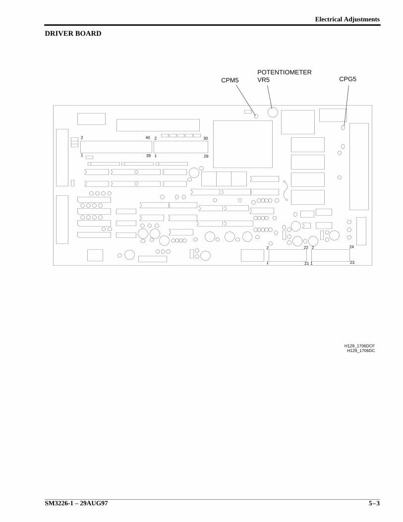
Electrical Adjustments
SM3226-1 – 29AUG97 5–3
DRIVER BOARD
29
30
39
40
1
2
1
2
H129_1706DC
1
2 22
21 1
2
23
24
CPM5 CPG5POTENTIOMETERVR5
H129_1706DCF
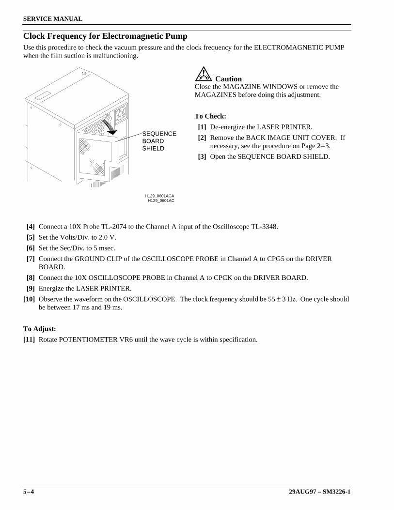
SERVICE MANUAL
5–4 29AUG97 – SM3226-1
Clock Frequency for Electromagnetic PumpUse this procedure to check the vacuum pressure and the clock frequency for the ELECTROMAGNETIC PUMPwhen the film suction is malfunctioning.
CautionClose the MAGAZINE WINDOWS or remove theMAGAZINES before doing this adjustment.
To Check:
[1] De-energize the LASER PRINTER.
[2] Remove the BACK IMAGE UNIT COVER. Ifnecessary, see the procedure on Page 2–3.
[3] Open the SEQUENCE BOARD SHIELD.
[4] Connect a 10X Probe TL-2074 to the Channel A input of the Oscilloscope TL-3348.
[5] Set the Volts/Div. to 2.0 V.
[6] Set the Sec/Div. to 5 msec.
[7] Connect the GROUND CLIP of the OSCILLOSCOPE PROBE in Channel A to CPG5 on the DRIVERBOARD.
[8] Connect the 10X OSCILLOSCOPE PROBE in Channel A to CPCK on the DRIVER BOARD.
[9] Energize the LASER PRINTER.
[10] Observe the waveform on the OSCILLOSCOPE. The clock frequency should be 55 ± 3 Hz. One cycle shouldbe between 17 ms and 19 ms.
To Adjust:
[11] Rotate POTENTIOMETER VR6 until the wave cycle is within specification.
H129_0601AC
SHIELDBOARDSEQUENCE
H129_0601ACA
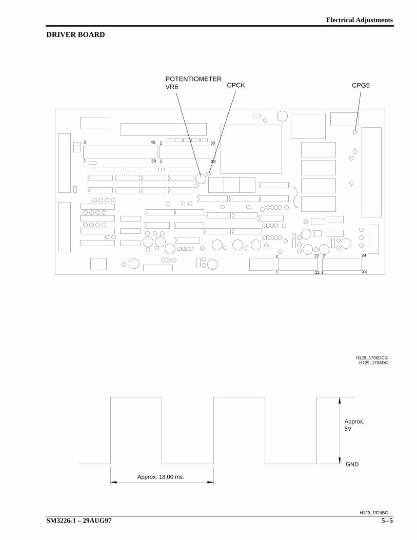
Electrical Adjustments
SM3226-1 – 29AUG97 5–5
DRIVER BOARD
29
30
39
40
1
2
1
2
H129_1706DC
1
2 22
21 1
2
23
24
H129_1706DCG
CPG5CPCKVR6POTENTIOMETER
H129_1924BC
GND
5VApprox.
Approx. 18.00 ms.
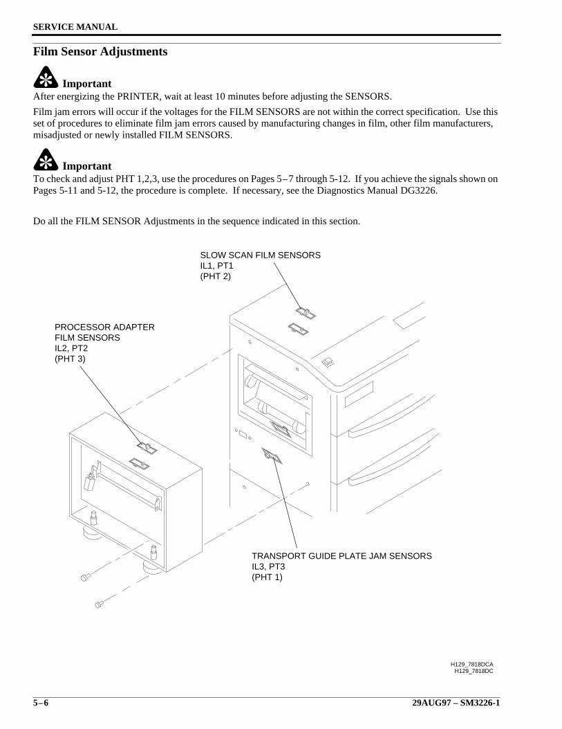
SERVICE MANUAL
5–6 29AUG97 – SM3226-1
Film Sensor Adjustments
ImportantAfter energizing the PRINTER, wait at least 10 minutes before adjusting the SENSORS.
Film jam errors will occur if the voltages for the FILM SENSORS are not within the correct specification. Use thisset of procedures to eliminate film jam errors caused by manufacturing changes in film, other film manufacturers,misadjusted or newly installed FILM SENSORS.
ImportantTo check and adjust PHT 1,2,3, use the procedures on Pages 5–7 through 5-12. If you achieve the signals shown onPages 5-11 and 5-12, the procedure is complete. If necessary, see the Diagnostics Manual DG3226.
Do all the FILM SENSOR Adjustments in the sequence indicated in this section.
H129_7818DCH129_7818DCA
SLOW SCAN FILM SENSORSIL1, PT1(PHT 2)
TRANSPORT GUIDE PLATE JAM SENSORSIL3, PT3(PHT 1)
PROCESSOR ADAPTERFILM SENSORSIL2, PT2(PHT 3)
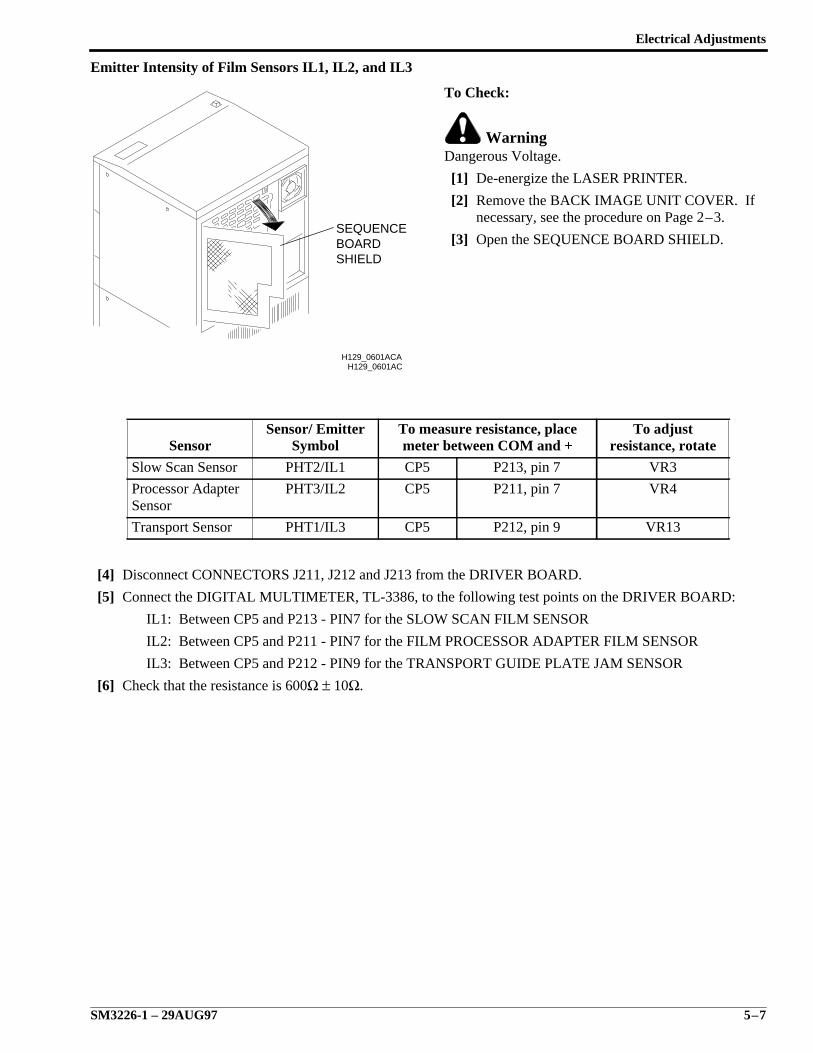
Electrical Adjustments
SM3226-1 – 29AUG97 5–7
Emitter Intensity of Film Sensors IL1, IL2, and IL3
To Check:
WarningDangerous Voltage.
[1] De-energize the LASER PRINTER.
[2] Remove the BACK IMAGE UNIT COVER. Ifnecessary, see the procedure on Page 2–3.
[3] Open the SEQUENCE BOARD SHIELD.
[4] Disconnect CONNECTORS J211, J212 and J213 from the DRIVER BOARD.
[5] Connect the DIGITAL MULTIMETER, TL-3386, to the following test points on the DRIVER BOARD:
IL1: Between CP5 and P213 - PIN7 for the SLOW SCAN FILM SENSOR
IL2: Between CP5 and P211 - PIN7 for the FILM PROCESSOR ADAPTER FILM SENSOR
IL3: Between CP5 and P212 - PIN9 for the TRANSPORT GUIDE PLATE JAM SENSOR
[6] Check that the resistance is 600Ω ± 10Ω.
SensorSensor/ Emitter
SymbolTo measure resistance, placemeter between COM and +
To adjustresistance, rotate
Slow Scan Sensor PHT2/IL1 CP5 P213, pin 7 VR3
Processor AdapterSensor
PHT3/IL2 CP5 P211, pin 7 VR4
Transport Sensor PHT1/IL3 CP5 P212, pin 9 VR13
H129_0601AC
SHIELDBOARDSEQUENCE
H129_0601ACA
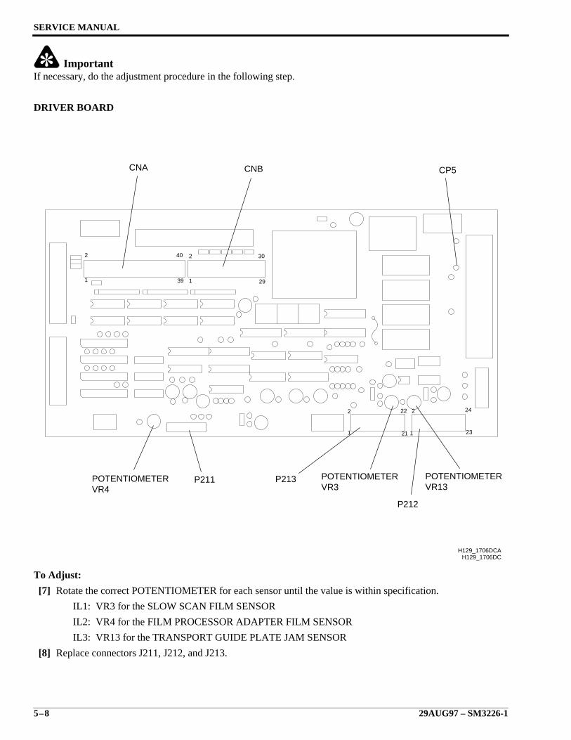
SERVICE MANUAL
5–8 29AUG97 – SM3226-1
ImportantIf necessary, do the adjustment procedure in the following step.
DRIVER BOARD
To Adjust:
[7] Rotate the correct POTENTIOMETER for each sensor until the value is within specification.
IL1: VR3 for the SLOW SCAN FILM SENSOR
IL2: VR4 for the FILM PROCESSOR ADAPTER FILM SENSOR
IL3: VR13 for the TRANSPORT GUIDE PLATE JAM SENSOR
[8] Replace connectors J211, J212, and J213.
29
30
39
40
1
2
1
2
H129_1706DC
1
2 22
21 1
2
23
24
CNA CNB CP5
POTENTIOMETERVR4
P211 P213
P212
POTENTIOMETERVR3
POTENTIOMETERVR13
H129_1706DCA

Electrical Adjustments
SM3226-1 – 29AUG97 5–9
Output Voltage for Receivers PT1, PT2, and PT3Perform this procedure to ensure the output voltages of RECEIVERS PT1, PT2, and PT3 are correct for the DRIVERBOARD to convert to a TTL level used at the SEQUENCE BOARD. It will be necessary to check this output whenchanging film manufacturers, replacing sensors and/or DRIVER BOARD.
To Check:
[1] Connect the Channel A and the Channel B GROUND CLIPS to CPG5.
[2] Connect the Channel A OSCILLOSCOPE PROBE to the correct TEST POINT:
NoteThis gives the analog output of each FILM JAM SENSOR.
• PH2 for the SLOW SCAN FILM SENSOR
• PH3 for the FILM PROCESSOR ADAPTER FILM SENSOR
• PH1 for the TRANSPORT GUIDE PLATE FILM SENSOR
[3] Set the Sec/Div to 2 ms/division.
[4] Set the Volts/Div to 1.0V for both Channel A and Channel B.
[5] Connect the Channel B OSCILLOSCOPE PROBE to the correct TEST POINT:
NoteThis shows the TTL levels for each FILM JAM SENSOR as converted by the DRIVER BOARD.
• PHT2 for the SLOW SCAN FILM SENSOR
• PHT3 for the FILM PROCESSOR ADAPTER FILM SENSOR
• PHT1 for the TRANSPORT GUIDE PLATE FILM SENSOR
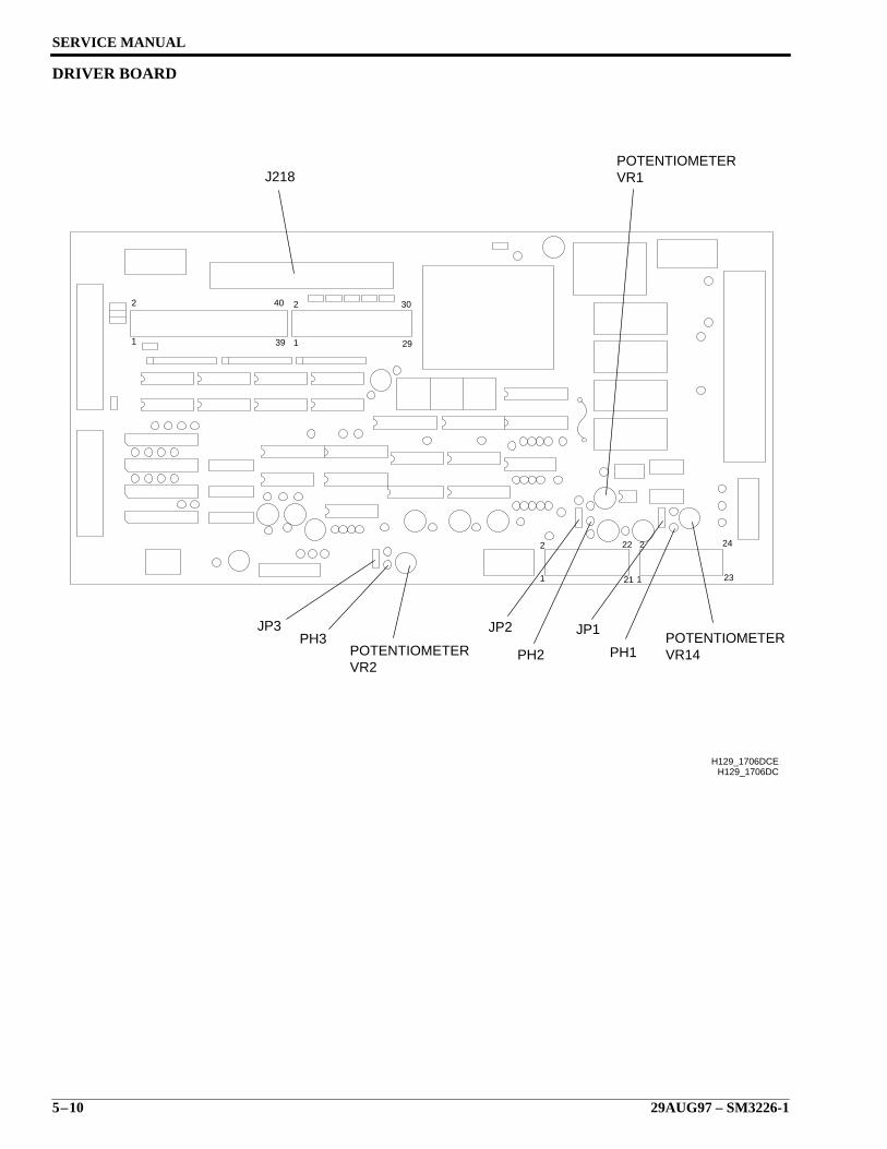
SERVICE MANUAL
5–10 29AUG97 – SM3226-1
DRIVER BOARD
29
30
39
40
1
2
1
2
H129_1706DC
1
2 22
21 1
2
23
24
H129_1706DCE
VR14POTENTIOMETER
VR2POTENTIOMETER
PH3JP3 JP2
PH2
JP1
PH1
VR1POTENTIOMETER
J218
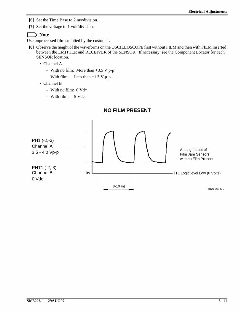
Electrical Adjustments
SM3226-1 – 29AUG97 5–11
[6] Set the Time Base to 2 ms/division.
[7] Set the voltage to 1 volt/division.
NoteUse unprocessed film supplied by the customer.
[8] Observe the height of the waveforms on the OSCILLOSCOPE first without FILM and then with FILM insertedbetween the EMITTER and RECEIVER of the SENSOR. If necessary, see the Component Locator for eachSENSOR location.
• Channel A
– With no film: More than +3.5 V p-p
– With film: Less than +1.5 V p-p
• Channel B
– With no film: 0 Vdc
– With film: 5 Vdc
8-10 ms
Channel A
Channel B
PH1 (-2,-3)
3.5 - 4.0 Vp-p
0 Vdc
PHT1 (-2,-3)
NO FILM PRESENT
0V
H129_2714BC
Analog output ofFilm Jam Sensorswith no Film Present
TTL Logic level Low (0 Volts)
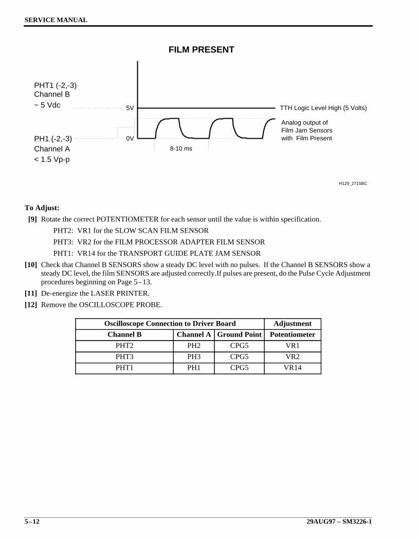
SERVICE MANUAL
5–12 29AUG97 – SM3226-1
To Adjust:
[9] Rotate the correct POTENTIOMETER for each sensor until the value is within specification.
PHT2: VR1 for the SLOW SCAN FILM SENSOR
PHT3: VR2 for the FILM PROCESSOR ADAPTER FILM SENSOR
PHT1: VR14 for the TRANSPORT GUIDE PLATE JAM SENSOR
[10] Check that Channel B SENSORS show a steady DC level with no pulses. If the Channel B SENSORS show asteady DC level, the film SENSORS are adjusted correctly.If pulses are present, do the Pulse Cycle Adjustmentprocedures beginning on Page 5–13.
[11] De-energize the LASER PRINTER.
[12] Remove the OSCILLOSCOPE PROBE.
Oscilloscope Connection to Driver Board Adjustment
Channel B Channel A Ground Point Potentiometer
PHT2 PH2 CPG5 VR1
PHT3 PH3 CPG5 VR2
PHT1 PH1 CPG5 VR14
Channel A
Channel B
PH1 (-2,-3)
< 1.5 Vp-p
~ 5 Vdc
PHT1 (-2,-3)
FILM PRESENT
Analog output ofFilm Jam Sensorswith Film Present
TTH Logic Level High (5 Volts)
0V
8-10 ms
5V
H129_2715BC
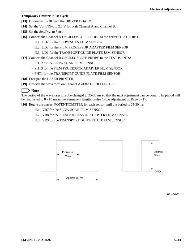
Electrical Adjustments
SM3226-1 – 29AUG97 5–13
Temporary Emitter Pulse Cycle
[13] Disconnect J218 from the DRIVER BOARD.
[14] Set the Volts/Div. to 2.0 V for both Channel A and Channel B.
[15] Set the Sec/Div. to 5 ms.
[16] Connect the Channel A OSCILLOSCOPE PROBE to the correct TEST POINT:
IL1: LD2 for the SLOW SCAN FILM SENSOR
IL2: LD3 for the FILM PROCESSOR ADAPTER FILM SENSOR
IL3: LD1 for the TRANSPORT GUIDE PLATE JAM SENSOR
[17] Connect the Channel B OSCILLOSCOPE PROBE to the TEST POINTS:
• PHT2 for the SLOW SCAN FILM SENSOR
• PHT3 for the FILM PROCESSOR ADAPTER FILM SENSOR
• PHT1 for the TRANSPORT GUIDE PLATE FILM SENSOR
[18] Energize the LASER PRINTER.
[19] Observe the waveform on Channel A of the OSCILLOSCOPE.
NoteThe period of the waveform must be changed to 25-30 ms so that the next adjustment can be done. The period willbe readjusted to 8 - 10 ms in the Permanent Emitter Pulse Cycle adjustment on Page 5–17.
[20] Rotate the correct POTENTIOMETER for each sensor until the period is 25-30 ms.
IL1: VR7 for the SLOW SCAN FILM SENSOR
IL2: VR8 for the FILM PROCESSOR ADAPTER FILM SENSOR
IL3: VR9 for the TRANSPORT GUIDE PLATE JAM SENSOR
Approx. 30 ms.
Approx.3.5 V
Emission
Time
GND
H129_1910BC
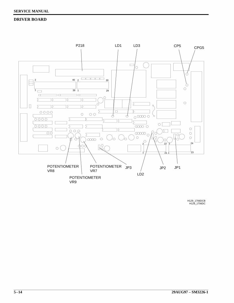
SERVICE MANUAL
5–14 29AUG97 – SM3226-1
DRIVER BOARD
29
30
39
40
1
2
1
2
H129_1706DC
1
2 22
21 1
2
23
24
POTENTIOMETERPOTENTIOMETERVR8 VR7
POTENTIOMETERVR9
P218
LD2
JP3 JP2
H129_1706DCB
JP1
LD1 LD3 CPG5CP5
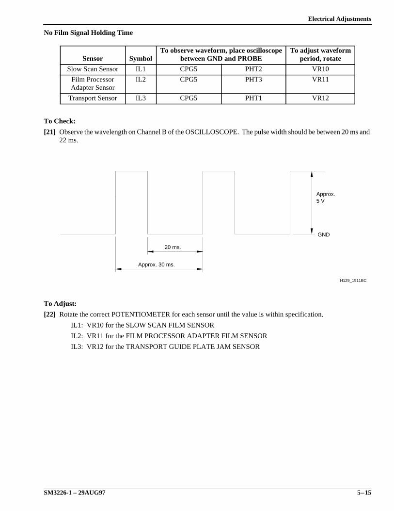
Electrical Adjustments
SM3226-1 – 29AUG97 5–15
No Film Signal Holding Time
To Check:
[21] Observe the wavelength on Channel B of the OSCILLOSCOPE. The pulse width should be between 20 ms and22 ms.
To Adjust:
[22] Rotate the correct POTENTIOMETER for each sensor until the value is within specification.
IL1: VR10 for the SLOW SCAN FILM SENSOR
IL2: VR11 for the FILM PROCESSOR ADAPTER FILM SENSOR
IL3: VR12 for the TRANSPORT GUIDE PLATE JAM SENSOR
Sensor SymbolTo observe waveform, place oscilloscope
between GND and PROBETo adjust waveform
period, rotate
Slow Scan Sensor IL1 CPG5 PHT2 VR10
Film ProcessorAdapter Sensor
IL2 CPG5 PHT3 VR11
Transport Sensor IL3 CPG5 PHT1 VR12
20 ms.
Approx.5 V
GND
Approx. 30 ms.
H129_1911BC
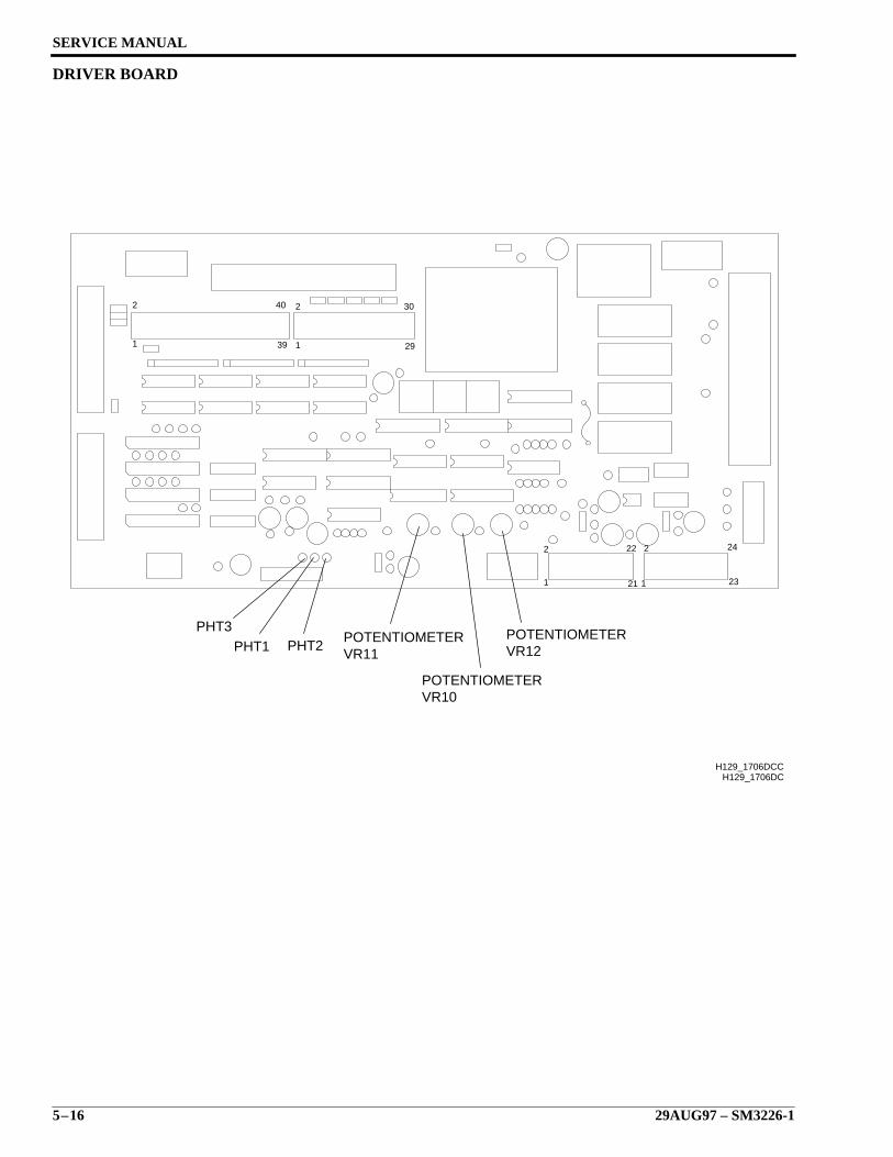
SERVICE MANUAL
5–16 29AUG97 – SM3226-1
DRIVER BOARD
29
30
39
40
1
2
1
2
H129_1706DC
1
2 22
21 1
2
23
24
H129_1706DCC
VR10POTENTIOMETER
VR12POTENTIOMETER
VR11POTENTIOMETER
PHT3PHT2PHT1
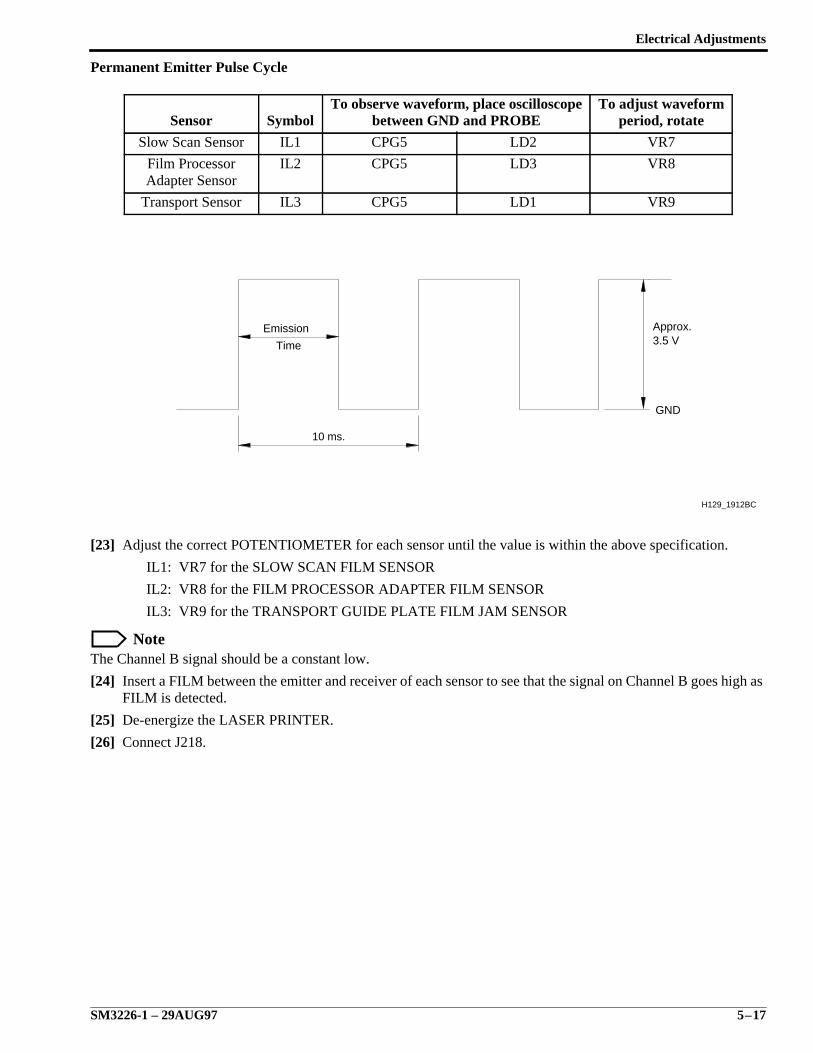
Electrical Adjustments
SM3226-1 – 29AUG97 5–17
Permanent Emitter Pulse Cycle
[23] Adjust the correct POTENTIOMETER for each sensor until the value is within the above specification.
IL1: VR7 for the SLOW SCAN FILM SENSOR
IL2: VR8 for the FILM PROCESSOR ADAPTER FILM SENSOR
IL3: VR9 for the TRANSPORT GUIDE PLATE FILM JAM SENSOR
NoteThe Channel B signal should be a constant low.
[24] Insert a FILM between the emitter and receiver of each sensor to see that the signal on Channel B goes high asFILM is detected.
[25] De-energize the LASER PRINTER.
[26] Connect J218.
Sensor SymbolTo observe waveform, place oscilloscope
between GND and PROBETo adjust waveform
period, rotate
Slow Scan Sensor IL1 CPG5 LD2 VR7
Film ProcessorAdapter Sensor
IL2 CPG5 LD3 VR8
Transport Sensor IL3 CPG5 LD1 VR9
10 ms.
H129_1912BC
GND
Time
Emission3.5 VApprox.
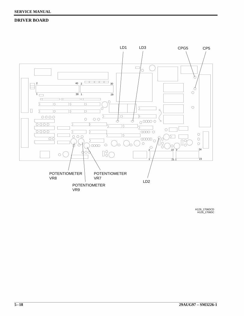
SERVICE MANUAL
5–18 29AUG97 – SM3226-1
DRIVER BOARD
29
30
39
40
1
2
1
2
H129_1706DC
1
2 22
21 1
2
23
24
POTENTIOMETERPOTENTIOMETERVR8
POTENTIOMETERVR9
VR7LD2
H129_1706DCD
CPG5LD1 LD3 CP5

Electrical Adjustments
SM3226-1 – 29AUG97 5–19
Emitter Pulse Duty Ratio for IL1, IL2, and IL3
Duty Cycle Ratio is defined as percent of time the SENSORS are on divided by the percent of time the SENSORSare off.
Lower the Duty Cycle Ratio if film fogging has occurred. Adjusting the 3 SWITCHES changes the ratio of emittertime per cycle. The Duty Ratio may need to be changed when non-Kodak films are used.
NoteThe switches RSW1 and RSW2 on the DRIVER BOARD are factory-set to 8 for a Duty Ratio of 60%. RSW3 isfactory set to 3 for a Duty Ration of 28 percent.
PHT2, IL1 - RSW2: for the SLOW SCAN FILM SENSOR
PHT3, IL2 - RSW3: for the FILM PROCESSOR ADAPTER SENSOR
PHT1, IL3 - RSW1: for the TRANSPORT GUIDE PLATE FILM JAM SENSOR
NoteIf changing the Duty Ratio, select one of the following switch settings to select the percent shown:
* Not recommended.
ImportantIf you change the Duty Ratio, the Output Voltage for Receivers will need to be checked. Adjust as necessary.
Switch Setting Duty Ratio Switch Setting Duty Ratio
*0 9.4% 8 60%
*1 16% 9 66%
2 22% *A 72%
3 28% *B 78%
4 34% *C 84%
5 41% *D 91%
6 47% *E 97%
7 53% *F 100%
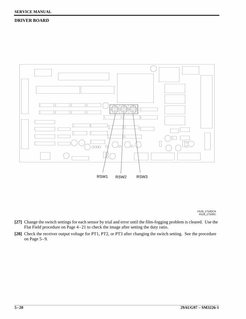
SERVICE MANUAL
5–20 29AUG97 – SM3226-1
DRIVER BOARD
[27] Change the switch settings for each sensor by trial and error until the film-fogging problem is cleared. Use theFlat Field procedure on Page 4–21 to check the image after setting the duty ratio.
[28] Check the receiver output voltage for PT1, PT2, or PT3 after changing the switch setting. See the procedureon Page 5–9.
H129_1710DCH129_1710DCA
RSW3RSW2RSW1
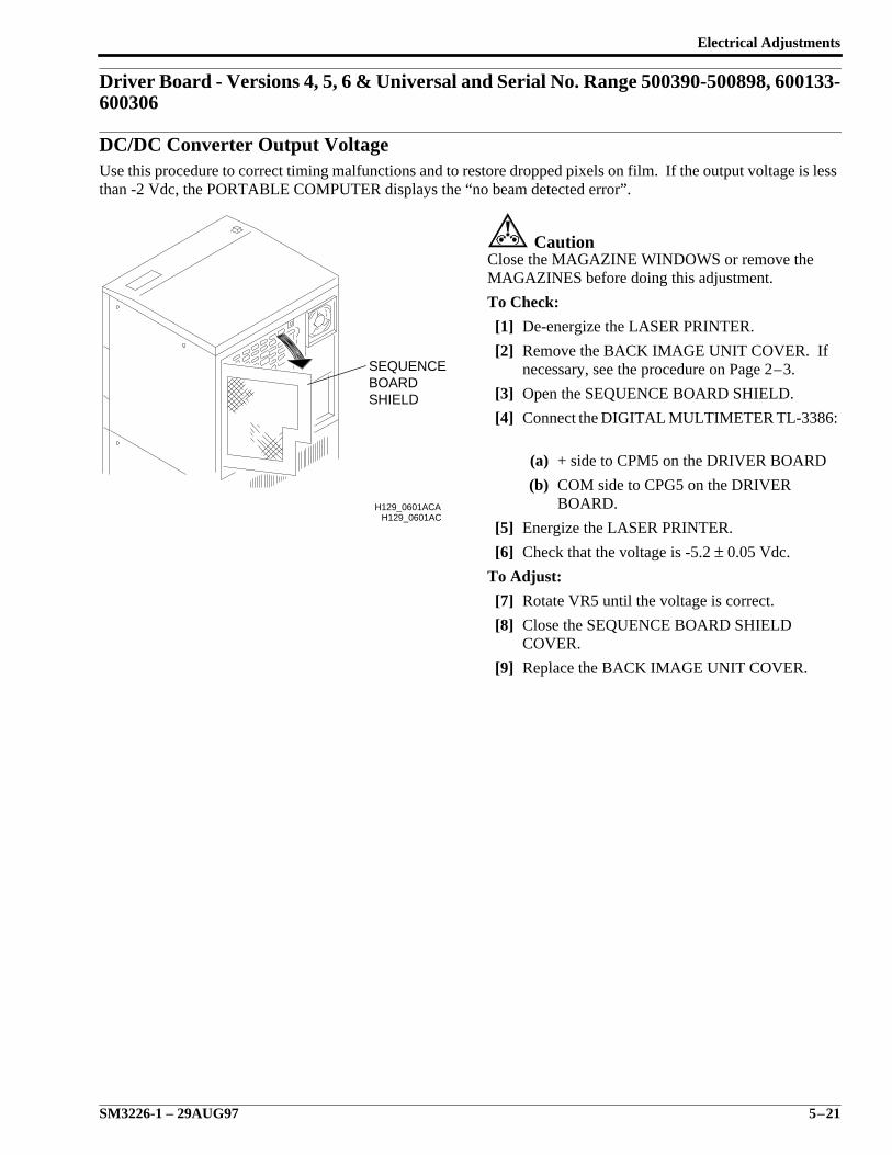
Electrical Adjustments
SM3226-1 – 29AUG97 5–21
Driver Board - Versions 4, 5, 6 & Universal and Serial No. Range 500390-500898, 600133-600306
DC/DC Converter Output VoltageUse this procedure to correct timing malfunctions and to restore dropped pixels on film. If the output voltage is lessthan -2 Vdc, the PORTABLE COMPUTER displays the “no beam detected error”.
CautionClose the MAGAZINE WINDOWS or remove theMAGAZINES before doing this adjustment.
To Check:
[1] De-energize the LASER PRINTER.
[2] Remove the BACK IMAGE UNIT COVER. Ifnecessary, see the procedure on Page 2–3.
[3] Open the SEQUENCE BOARD SHIELD.
[4] Connect the DIGITAL MULTIMETER TL-3386:
(a) + side to CPM5 on the DRIVER BOARD
(b) COM side to CPG5 on the DRIVERBOARD.
[5] Energize the LASER PRINTER.
[6] Check that the voltage is -5.2 ± 0.05 Vdc.
To Adjust:
[7] Rotate VR5 until the voltage is correct.
[8] Close the SEQUENCE BOARD SHIELDCOVER.
[9] Replace the BACK IMAGE UNIT COVER.
H129_0601AC
SHIELDBOARDSEQUENCE
H129_0601ACA
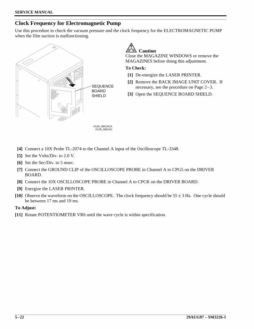
SERVICE MANUAL
5–22 29AUG97 – SM3226-1
Clock Frequency for Electromagnetic PumpUse this procedure to check the vacuum pressure and the clock frequency for the ELECTROMAGNETIC PUMPwhen the film suction is malfunctioning.
CautionClose the MAGAZINE WINDOWS or remove theMAGAZINES before doing this adjustment.
To Check:
[1] De-energize the LASER PRINTER.
[2] Remove the BACK IMAGE UNIT COVER. Ifnecessary, see the procedure on Page 2–3.
[3] Open the SEQUENCE BOARD SHIELD.
[4] Connect a 10X Probe TL-2074 to the Channel A input of the Oscilloscope TL-3348.
[5] Set the Volts/Div. to 2.0 V.
[6] Set the Sec/Div. to 5 msec.
[7] Connect the GROUND CLIP of the OSCILLOSCOPE PROBE in Channel A to CPG5 on the DRIVERBOARD.
[8] Connect the 10X OSCILLOSCOPE PROBE in Channel A to CPCK on the DRIVER BOARD.
[9] Energize the LASER PRINTER.
[10] Observe the waveform on the OSCILLOSCOPE. The clock frequency should be 55 ± 3 Hz. One cycle shouldbe between 17 ms and 19 ms.
To Adjust:
[11] Rotate POTENTIOMETER VR6 until the wave cycle is within specification.
H129_0601AC
SHIELDBOARDSEQUENCE
H129_0601ACA
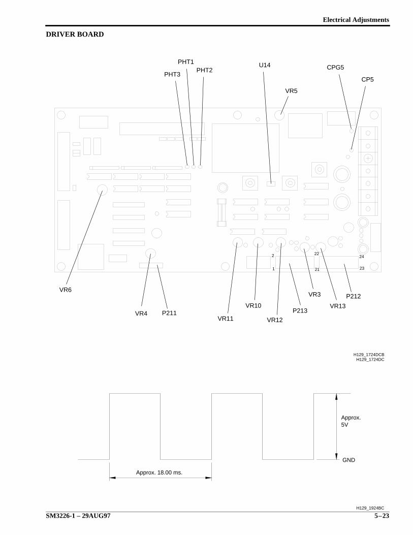
Electrical Adjustments
SM3226-1 – 29AUG97 5–23
DRIVER BOARD
23
24
21
222
1
H129_1724DC
VR4 P211VR11
VR10
VR12
P213
VR3
VR13
P212
CP5
CPG5U14PHT2
PHT1
PHT3
H129_1724DCB
VR6
VR5
H129_1924BC
GND
5VApprox.
Approx. 18.00 ms.
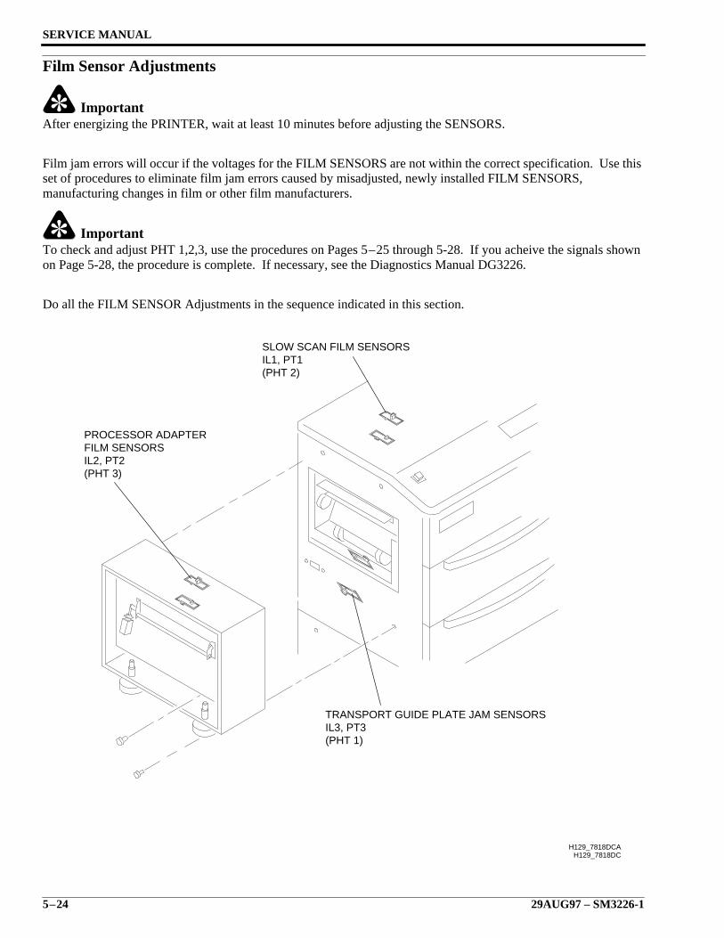
SERVICE MANUAL
5–24 29AUG97 – SM3226-1
Film Sensor Adjustments
ImportantAfter energizing the PRINTER, wait at least 10 minutes before adjusting the SENSORS.
Film jam errors will occur if the voltages for the FILM SENSORS are not within the correct specification. Use thisset of procedures to eliminate film jam errors caused by misadjusted, newly installed FILM SENSORS,manufacturing changes in film or other film manufacturers.
ImportantTo check and adjust PHT 1,2,3, use the procedures on Pages 5–25 through 5-28. If you acheive the signals shownon Page 5-28, the procedure is complete. If necessary, see the Diagnostics Manual DG3226.
Do all the FILM SENSOR Adjustments in the sequence indicated in this section.
H129_7818DCH129_7818DCA
SLOW SCAN FILM SENSORSIL1, PT1(PHT 2)
TRANSPORT GUIDE PLATE JAM SENSORSIL3, PT3(PHT 1)
PROCESSOR ADAPTERFILM SENSORSIL2, PT2(PHT 3)
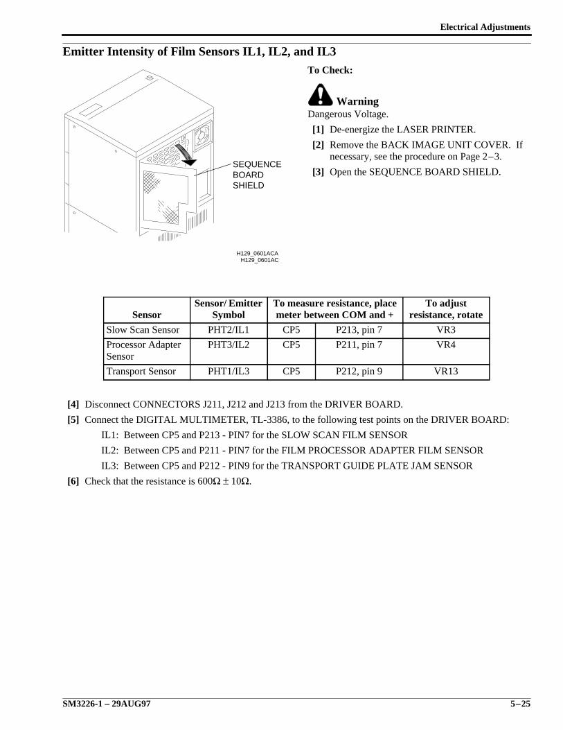
Electrical Adjustments
SM3226-1 – 29AUG97 5–25
Emitter Intensity of Film Sensors IL1, IL2, and IL3To Check:
WarningDangerous Voltage.
[1] De-energize the LASER PRINTER.
[2] Remove the BACK IMAGE UNIT COVER. Ifnecessary, see the procedure on Page 2–3.
[3] Open the SEQUENCE BOARD SHIELD.
[4] Disconnect CONNECTORS J211, J212 and J213 from the DRIVER BOARD.
[5] Connect the DIGITAL MULTIMETER, TL-3386, to the following test points on the DRIVER BOARD:
IL1: Between CP5 and P213 - PIN7 for the SLOW SCAN FILM SENSOR
IL2: Between CP5 and P211 - PIN7 for the FILM PROCESSOR ADAPTER FILM SENSOR
IL3: Between CP5 and P212 - PIN9 for the TRANSPORT GUIDE PLATE JAM SENSOR
[6] Check that the resistance is 600Ω ± 10Ω.
SensorSensor/ Emitter
SymbolTo measure resistance, placemeter between COM and +
To adjustresistance, rotate
Slow Scan Sensor PHT2/IL1 CP5 P213, pin 7 VR3
Processor AdapterSensor
PHT3/IL2 CP5 P211, pin 7 VR4
Transport Sensor PHT1/IL3 CP5 P212, pin 9 VR13
H129_0601AC
SHIELDBOARDSEQUENCE
H129_0601ACA
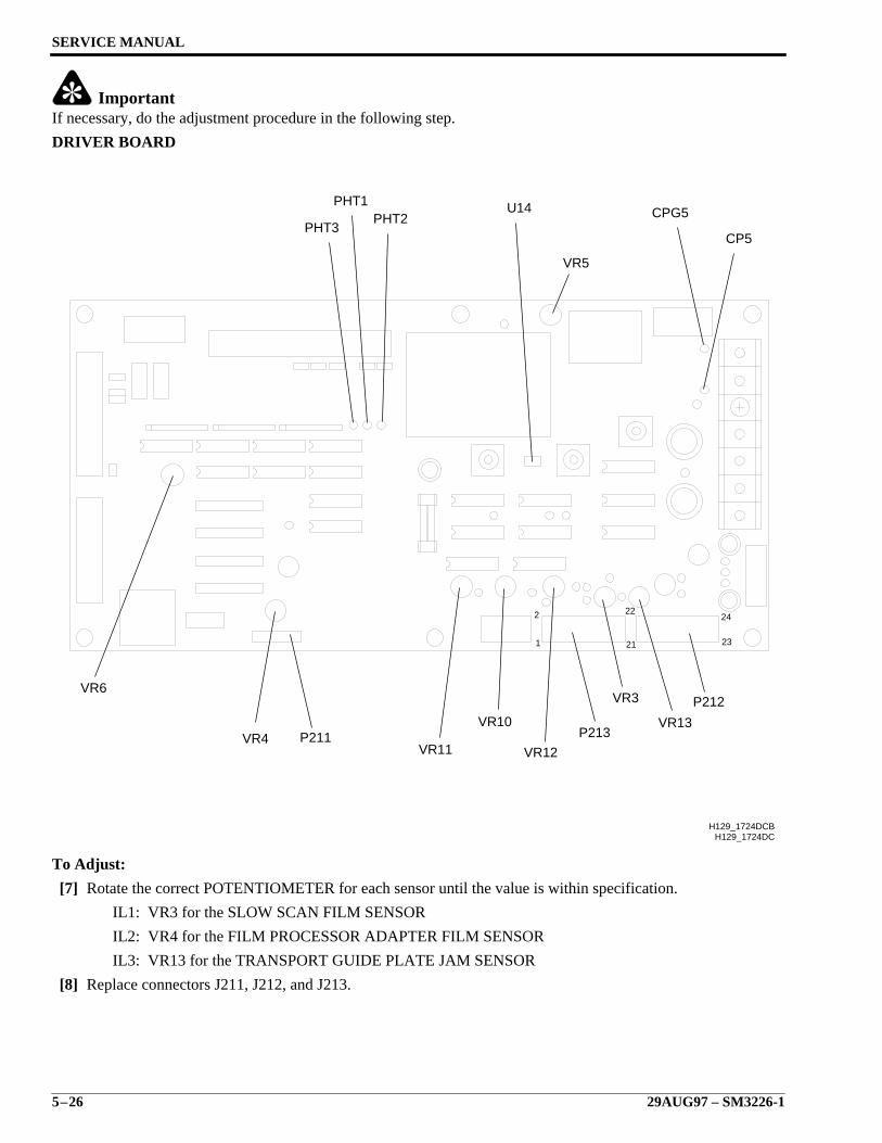
SERVICE MANUAL
5–26 29AUG97 – SM3226-1
ImportantIf necessary, do the adjustment procedure in the following step.
DRIVER BOARD
To Adjust:
[7] Rotate the correct POTENTIOMETER for each sensor until the value is within specification.
IL1: VR3 for the SLOW SCAN FILM SENSOR
IL2: VR4 for the FILM PROCESSOR ADAPTER FILM SENSOR
IL3: VR13 for the TRANSPORT GUIDE PLATE JAM SENSOR
[8] Replace connectors J211, J212, and J213.
23
24
21
222
1
H129_1724DC
VR4 P211VR11
VR10
VR12
P213
VR3
VR13
P212
CP5
CPG5U14PHT2
PHT1
PHT3
H129_1724DCB
VR6
VR5

Electrical Adjustments
SM3226-1 – 29AUG97 5–27
Output Voltage for Receivers PT1, PT2, and PT3This procedure is done to ensure the necessary output voltages are correct for the DRIVER BOARD to convert to aTTL level used at the SEQUENCE BOARD. It will be necessary to check this output when changing filmmanufacturers, replacing sensors and/or DRIVER BOARD.
To Check:
[1] Connect the Channel A and the Channel B GROUND CLIPS to CPG5.
[2] Connect the Channel A OSCILLOSCOPE PROBE to the correct TEST POINT:
NoteThis gives the analog output of each FILM JAM SENSOR.
• PH2 for the SLOW SCAN FILM SENSOR
• PH3 for the FILM PROCESSOR ADAPTER FILM SENSOR
• PH1 for the TRANSPORT GUIDE PLATE FILM SENSOR
[3] Set the Time Base to 2 ms/division.
[4] Set the voltage to 1 volt/division.
[5] Connect the Channel B OSCILLOSCOPE PROBE to the correct TEST POINT:
NoteThis shows the TTL levels for each FILM JAM SENSOR as converted by the DRIVER BOARD.
• PHT2 for the SLOW SCAN FILM SENSOR
• PHT3 for the FILM PROCESSOR ADAPTER FILM SENSOR
• PHT1 for the TRANSPORT GUIDE PLATE FILM SENSOR
[6] Set the Time Base to 2 ms/division.
[7] Set the voltage to 1 volt/division.
NoteUse unprocessed film supplied by the customer.
[8] Observe the height of the waveforms on the OSCILLOSCOPE first without FILM and then with FILM insertedbetween the EMITTER and RECEIVER of the SENSOR. If necessary, see the Component Locator for eachSENSOR location.
• Channel A
– With no film: More than +3.5 V p-p
– With film: Less than +1.5 V p-p
• Channel B
– With no film: 0 Vdc
– With film: 5 Vdc
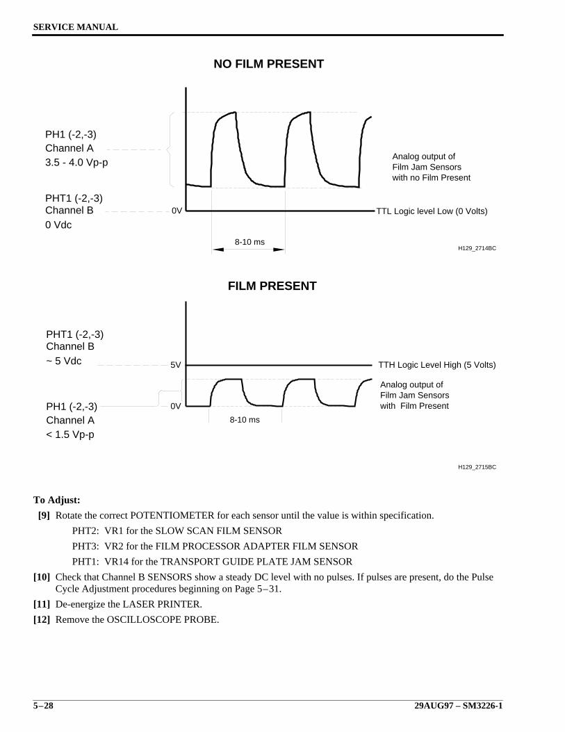
SERVICE MANUAL
5–28 29AUG97 – SM3226-1
To Adjust:
[9] Rotate the correct POTENTIOMETER for each sensor until the value is within specification.
PHT2: VR1 for the SLOW SCAN FILM SENSOR
PHT3: VR2 for the FILM PROCESSOR ADAPTER FILM SENSOR
PHT1: VR14 for the TRANSPORT GUIDE PLATE JAM SENSOR
[10] Check that Channel B SENSORS show a steady DC level with no pulses. If pulses are present, do the PulseCycle Adjustment procedures beginning on Page 5–31.
[11] De-energize the LASER PRINTER.
[12] Remove the OSCILLOSCOPE PROBE.
8-10 ms
Channel A
Channel B
PH1 (-2,-3)
3.5 - 4.0 Vp-p
0 Vdc
PHT1 (-2,-3)
NO FILM PRESENT
0V
H129_2714BC
Analog output ofFilm Jam Sensorswith no Film Present
TTL Logic level Low (0 Volts)
Channel A
Channel B
PH1 (-2,-3)
< 1.5 Vp-p
~ 5 Vdc
PHT1 (-2,-3)
FILM PRESENT
Analog output ofFilm Jam Sensorswith Film Present
TTH Logic Level High (5 Volts)
0V
8-10 ms
5V
H129_2715BC
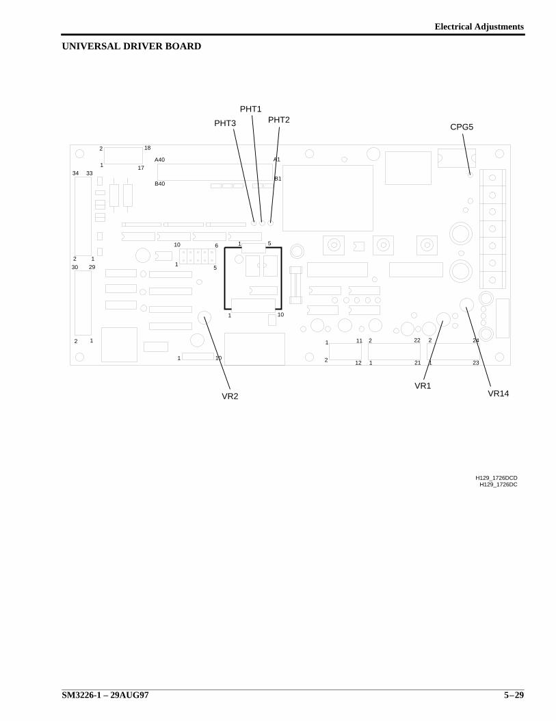
Electrical Adjustments
SM3226-1 – 29AUG97 5–29
UNIVERSAL DRIVER BOARD
H129_1726DC
33
1
2 22
21
24
23
1
2
11
12
2
1101
101
1 5
12
2
1
30 29
2 1
34
18
17A40
B40
A1
B1
10
15
6
H129_1726DCD
PHT3
PHT1PHT2
CPG5
VR2VR1
VR14
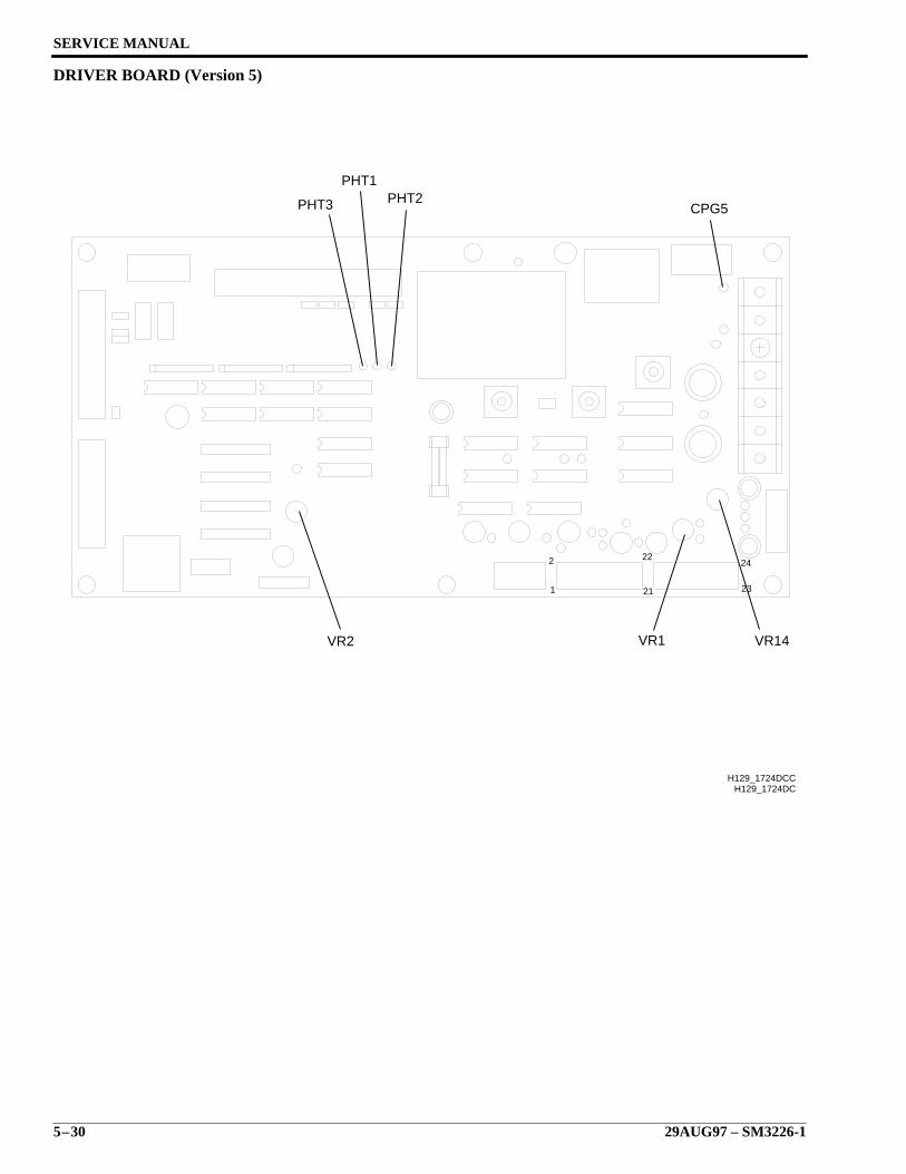
SERVICE MANUAL
5–30 29AUG97 – SM3226-1
DRIVER BOARD (Version 5)
23
24
21
222
1
H129_1724DC
VR14VR1VR2
CPG5PHT2
PHT1
PHT3
H129_1724DCC
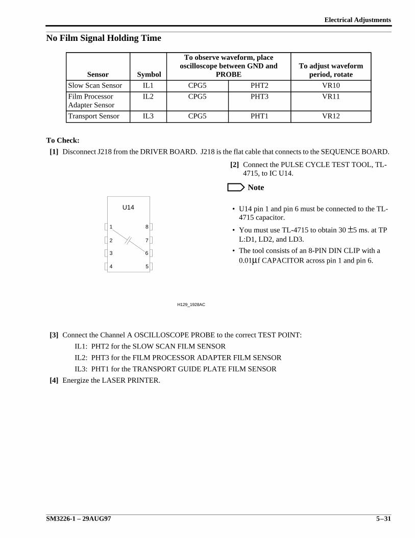
Electrical Adjustments
SM3226-1 – 29AUG97 5–31
No Film Signal Holding Time
To Check:
[1] Disconnect J218 from the DRIVER BOARD. J218 is the flat cable that connects to the SEQUENCE BOARD.
[2] Connect the PULSE CYCLE TEST TOOL, TL-4715, to IC U14.
Note
• U14 pin 1 and pin 6 must be connected to the TL-4715 capacitor.
• You must use TL-4715 to obtain 30 ±5 ms. at TPL:D1, LD2, and LD3.
• The tool consists of an 8-PIN DIN CLIP with a0.01µf CAPACITOR across pin 1 and pin 6.
[3] Connect the Channel A OSCILLOSCOPE PROBE to the correct TEST POINT:
IL1: PHT2 for the SLOW SCAN FILM SENSOR
IL2: PHT3 for the FILM PROCESSOR ADAPTER FILM SENSOR
IL3: PHT1 for the TRANSPORT GUIDE PLATE FILM SENSOR
[4] Energize the LASER PRINTER.
Sensor Symbol
To observe waveform, placeoscilloscope between GND and
PROBETo adjust waveform
period, rotate
Slow Scan Sensor IL1 CPG5 PHT2 VR10
Film ProcessorAdapter Sensor
IL2 CPG5 PHT3 VR11
Transport Sensor IL3 CPG5 PHT1 VR12
U14
1
2
3
4 5
6
7
8
H129_1928AC
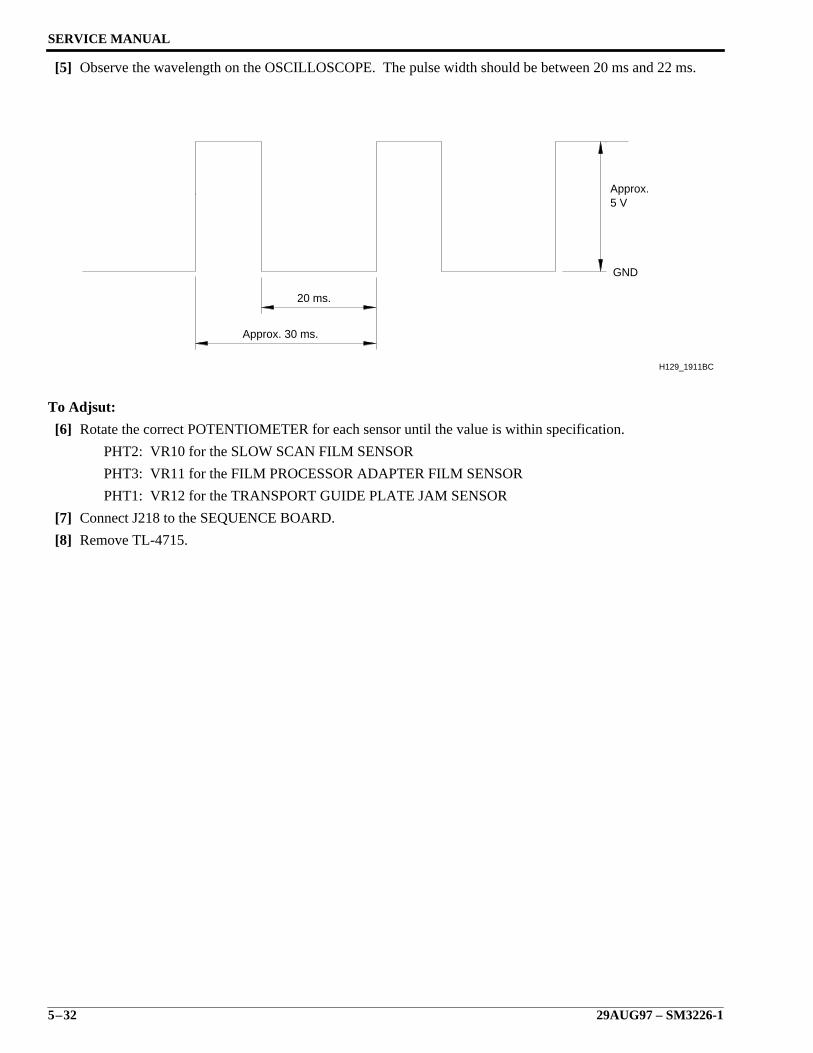
SERVICE MANUAL
5–32 29AUG97 – SM3226-1
[5] Observe the wavelength on the OSCILLOSCOPE. The pulse width should be between 20 ms and 22 ms.
To Adjsut:
[6] Rotate the correct POTENTIOMETER for each sensor until the value is within specification.
PHT2: VR10 for the SLOW SCAN FILM SENSOR
PHT3: VR11 for the FILM PROCESSOR ADAPTER FILM SENSOR
PHT1: VR12 for the TRANSPORT GUIDE PLATE JAM SENSOR
[7] Connect J218 to the SEQUENCE BOARD.
[8] Remove TL-4715.
20 ms.
Approx.5 V
GND
Approx. 30 ms.
H129_1911BC
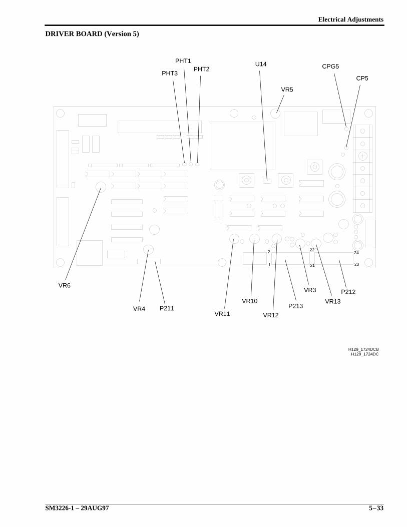
Electrical Adjustments
SM3226-1 – 29AUG97 5–33
DRIVER BOARD (Version 5)
23
24
21
222
1
H129_1724DC
VR4 P211VR11
VR10
VR12
P213
VR3
VR13
P212
CP5
CPG5U14PHT2
PHT1
PHT3
H129_1724DCB
VR6
VR5
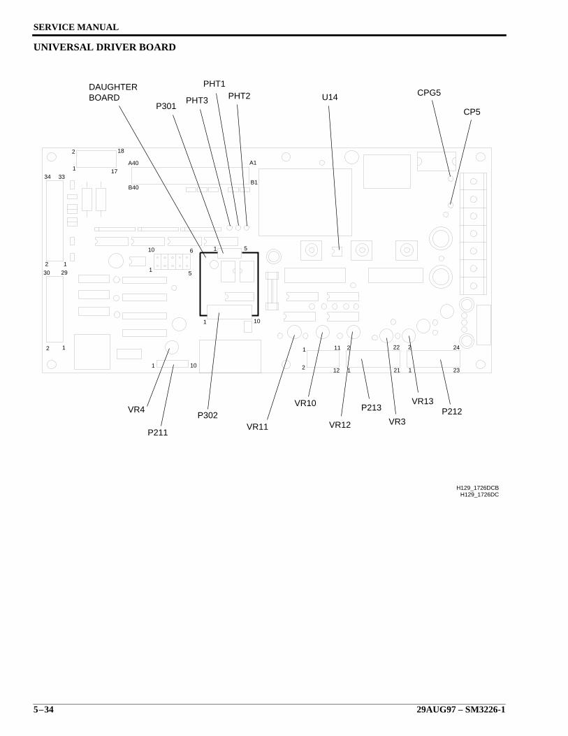
SERVICE MANUAL
5–34 29AUG97 – SM3226-1
UNIVERSAL DRIVER BOARD
H129_1726DC
33
1
2 22
21
24
23
1
2
11
12
2
1101
101
1 5
12
2
1
30 29
2 1
34
18
17A40
B40
A1
B1
10
15
6
H129_1726DCB
DAUGHTERBOARD
P301PHT3
PHT1PHT2 U14 CPG5
CP5
VR4
P211
P302VR11
VR10
VR12
P213
VR3
VR13P212
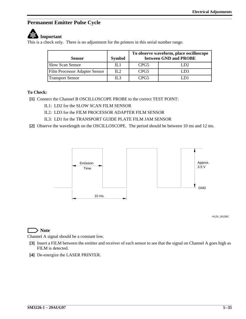
Electrical Adjustments
SM3226-1 – 29AUG97 5–35
Permanent Emitter Pulse Cycle
ImportantThis is a check only. There is no adjustment for the printers in this serial number range.
To Check:
[1] Connect the Channel B OSCILLOSCOPE PROBE to the correct TEST POINT:
IL1: LD2 for the SLOW SCAN FILM SENSOR
IL2: LD3 for the FILM PROCESSOR ADAPTER FILM SENSOR
IL3: LD1 for the TRANSPORT GUIDE PLATE FILM JAM SENSOR
[2] Observe the wavelength on the OSCILLOSCOPE. The period should be between 10 ms and 12 ms.
NoteChannel A signal should be a constant low.
[3] Insert a FILM between the emitter and receiver of each sensor to see that the signal on Channel A goes high asFILM is detected.
[4] De-energize the LASER PRINTER.
Sensor SymbolTo observe waveform, place oscilloscope
between GND and PROBE
Slow Scan Sensor IL1 CPG5 LD2
Film Processor Adapter Sensor IL2 CPG5 LD3
Transport Sensor IL3 CPG5 LD1
10 ms.
H129_1912BC
GND
Time
Emission3.5 VApprox.
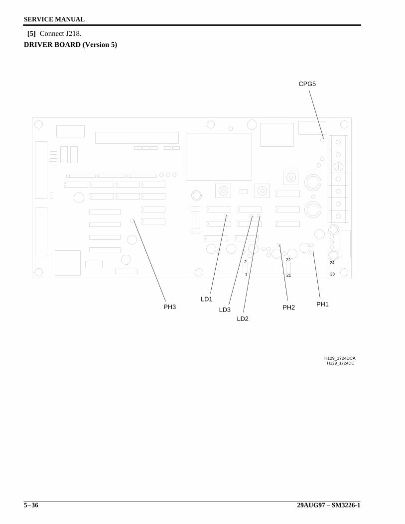
SERVICE MANUAL
5–36 29AUG97 – SM3226-1
[5] Connect J218.
DRIVER BOARD (Version 5)
23
24
21
222
1
H129_1724DCH129_1724DCA
PH1PH2
LD2LD3
LD1PH3
CPG5
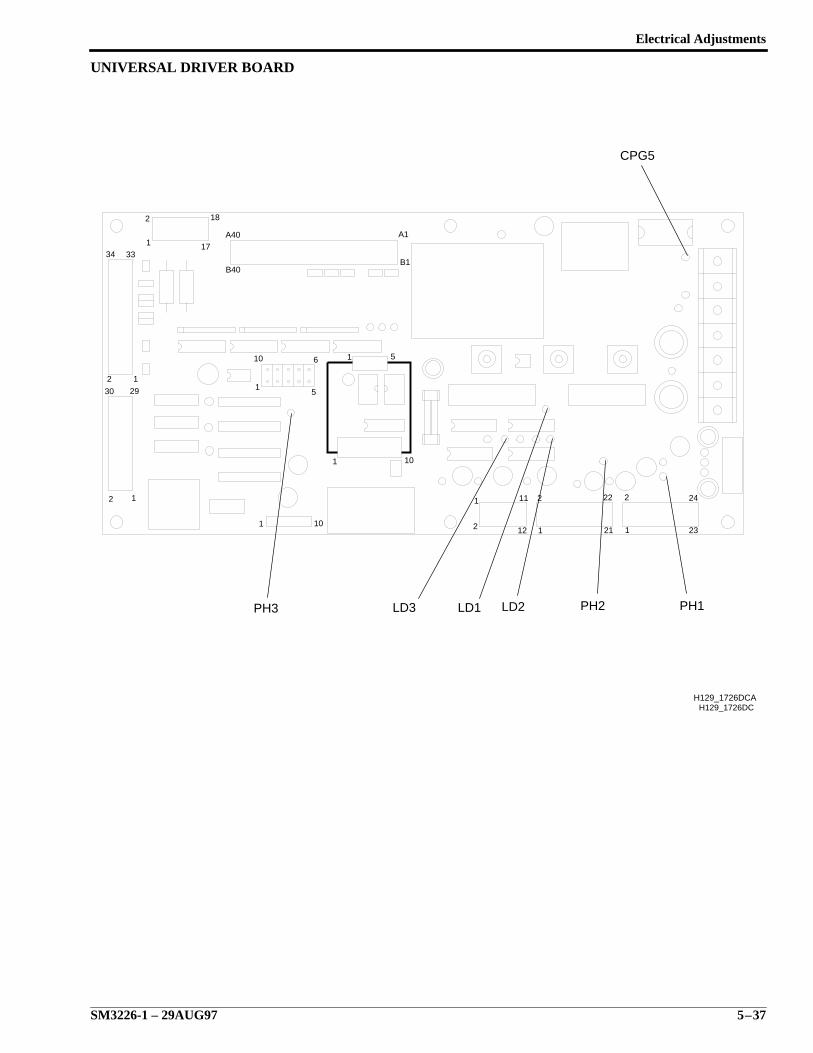
Electrical Adjustments
SM3226-1 – 29AUG97 5–37
UNIVERSAL DRIVER BOARD
H129_1726DC
33
1
2 22
21
24
23
1
2
11
12
2
1101
101
1 5
12
2
1
30 29
2 1
34
18
17A40
B40
A1
B1
10
15
6
H129_1726DCA
PH1PH2LD2LD1LD3PH3
CPG5

SERVICE MANUAL
5–38 29AUG97 – SM3226-1
Emitter Pulse Duty Ratio for Sensors IL1, IL2, and IL3Duty Cycle Ratio is defined as percent of time the SENSORS are on divided by the percent of time the SENSORSare off.
Lower the Duty Cycle Ratio if film fogging has occurred. Adjusting the 3 SWITCHES changes the ratio of emittertime per cycle. The Duty Ratio may need to be changed when non-Kodak films are used.
NoteThe switches RSW1 and RSW2 on the DRIVER BOARD are factory-set to 8 for a Duty Ratio of 60%. RSW3 isfactory set to 3 for a Duty Ration of 28 percent.
PHT2, IL1 - RSW2: for the SLOW SCAN FILM SENSOR
PHT3, IL2 - RSW3: for the FILM PROCESSOR ADAPTER SENSOR
PHT1, IL3 - RSW1: for the TRANSPORT GUIDE PLATE FILM JAM SENSOR
NoteIf changing the Duty Ratio, select one of the following switch settings to select the percent shown:
* Not recommended.
Switch Setting Duty Ratio Switch Setting Duty Ratio
*0 9.4% 8 60%
*1 16% 9 66%
2 22% *A 72%
3 28% *B 78%
4 34% *C 84%
5 41% *D 91%
6 47% *E 97%
7 53% *F 100%
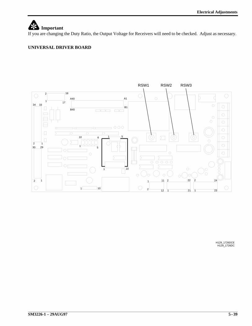
Electrical Adjustments
SM3226-1 – 29AUG97 5–39
ImportantIf you are changing the Duty Ratio, the Output Voltage for Receivers will need to be checked. Adjust as necessary.
UNIVERSAL DRIVER BOARD
H129_1726DC
33
1
2 22
21
24
23
1
2
11
12
2
1101
101
1 5
12
2
1
30 29
2 1
34
18
17A40
B40
A1
B1
10
15
6
RSW3
H129_1726DCE
RSW1 RSW2
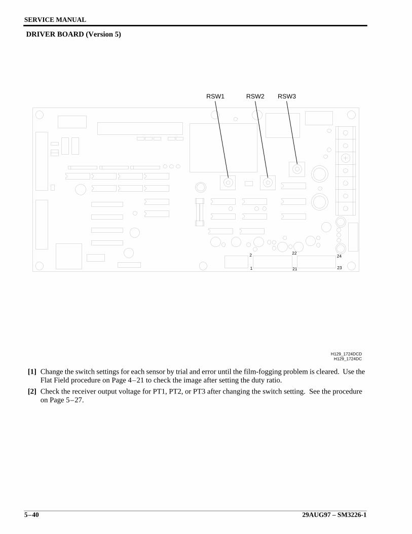
SERVICE MANUAL
5–40 29AUG97 – SM3226-1
DRIVER BOARD (Version 5)
[1] Change the switch settings for each sensor by trial and error until the film-fogging problem is cleared. Use theFlat Field procedure on Page 4–21 to check the image after setting the duty ratio.
[2] Check the receiver output voltage for PT1, PT2, or PT3 after changing the switch setting. See the procedureon Page 5–27.
23
24
21
222
1
H129_1724DC
RSW3RSW2RSW1
H129_1724DCD
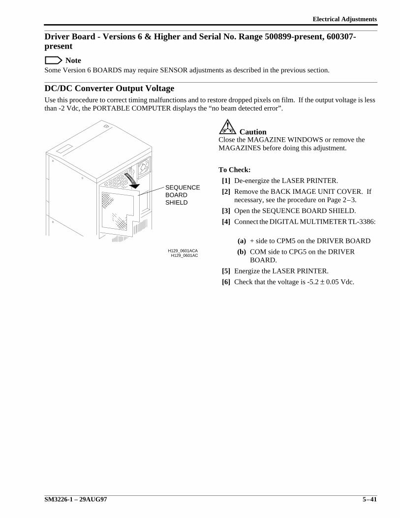
Electrical Adjustments
SM3226-1 – 29AUG97 5–41
Driver Board - Versions 6 & Higher and Serial No. Range 500899-present, 600307-present
NoteSome Version 6 BOARDS may require SENSOR adjustments as described in the previous section.
DC/DC Converter Output VoltageUse this procedure to correct timing malfunctions and to restore dropped pixels on film. If the output voltage is lessthan -2 Vdc, the PORTABLE COMPUTER displays the “no beam detected error”.
CautionClose the MAGAZINE WINDOWS or remove theMAGAZINES before doing this adjustment.
To Check:
[1] De-energize the LASER PRINTER.
[2] Remove the BACK IMAGE UNIT COVER. Ifnecessary, see the procedure on Page 2–3.
[3] Open the SEQUENCE BOARD SHIELD.
[4] Connect the DIGITAL MULTIMETER TL-3386:
(a) + side to CPM5 on the DRIVER BOARD
(b) COM side to CPG5 on the DRIVERBOARD.
[5] Energize the LASER PRINTER.
[6] Check that the voltage is -5.2 ± 0.05 Vdc.
H129_0601AC
SHIELDBOARDSEQUENCE
H129_0601ACA
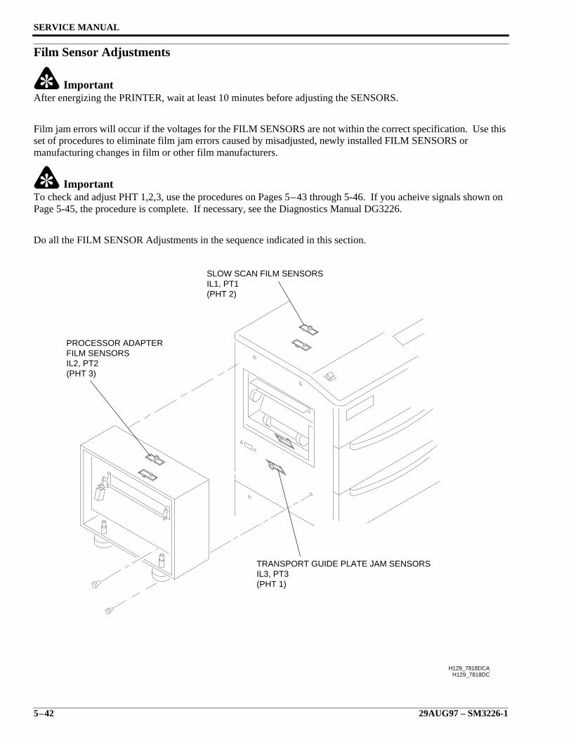
SERVICE MANUAL
5–42 29AUG97 – SM3226-1
Film Sensor Adjustments
ImportantAfter energizing the PRINTER, wait at least 10 minutes before adjusting the SENSORS.
Film jam errors will occur if the voltages for the FILM SENSORS are not within the correct specification. Use thisset of procedures to eliminate film jam errors caused by misadjusted, newly installed FILM SENSORS ormanufacturing changes in film or other film manufacturers.
ImportantTo check and adjust PHT 1,2,3, use the procedures on Pages 5–43 through 5-46. If you acheive signals shown onPage 5-45, the procedure is complete. If necessary, see the Diagnostics Manual DG3226.
Do all the FILM SENSOR Adjustments in the sequence indicated in this section.
H129_7818DCH129_7818DCA
SLOW SCAN FILM SENSORSIL1, PT1(PHT 2)
TRANSPORT GUIDE PLATE JAM SENSORSIL3, PT3(PHT 1)
PROCESSOR ADAPTERFILM SENSORSIL2, PT2(PHT 3)

Electrical Adjustments
SM3226-1 – 29AUG97 5–43
Output Voltage for Receivers PT1, PT2, and PT3This procedure is done to ensure the necessary output voltages are correct for the DRIVER BOARD to convert to aTTL level used at the SEQUENCE BOARD. It will be necessary to check this output when changing filmmanufacturers, replacing sensors and/or DRIVER BOARD.
To Check:
[1] Connect the Channel A and the Channel B GROUND CLIPS to CPG5.
[2] Connect the Channel A OSCILLOSCOPE PROBE to the correct TEST POINT:
NoteThis gives the analog output of each FILM JAM SENSOR.
• PH2 for the SLOW SCAN FILM SENSOR
• PH3 for the FILM PROCESSOR ADAPTER FILM SENSOR
• PH1 for the TRANSPORT GUIDE PLATE FILM SENSOR
[3] Set the Time Base to 2 ms/division.
[4] Set the voltage to 1 volt/division.
[5] Connect the Channel B OSCILLOSCOPE PROBE to the correct TEST POINT:
NoteThis shows the TTL levels for each FILM JAM SENSOR as converted by the DRIVER BOARD.
• PHT2 for the SLOW SCAN FILM SENSOR
• PHT3 for the FILM PROCESSOR ADAPTER FILM SENSOR
• PHT1 for the TRANSPORT GUIDE PLATE FILM SENSOR
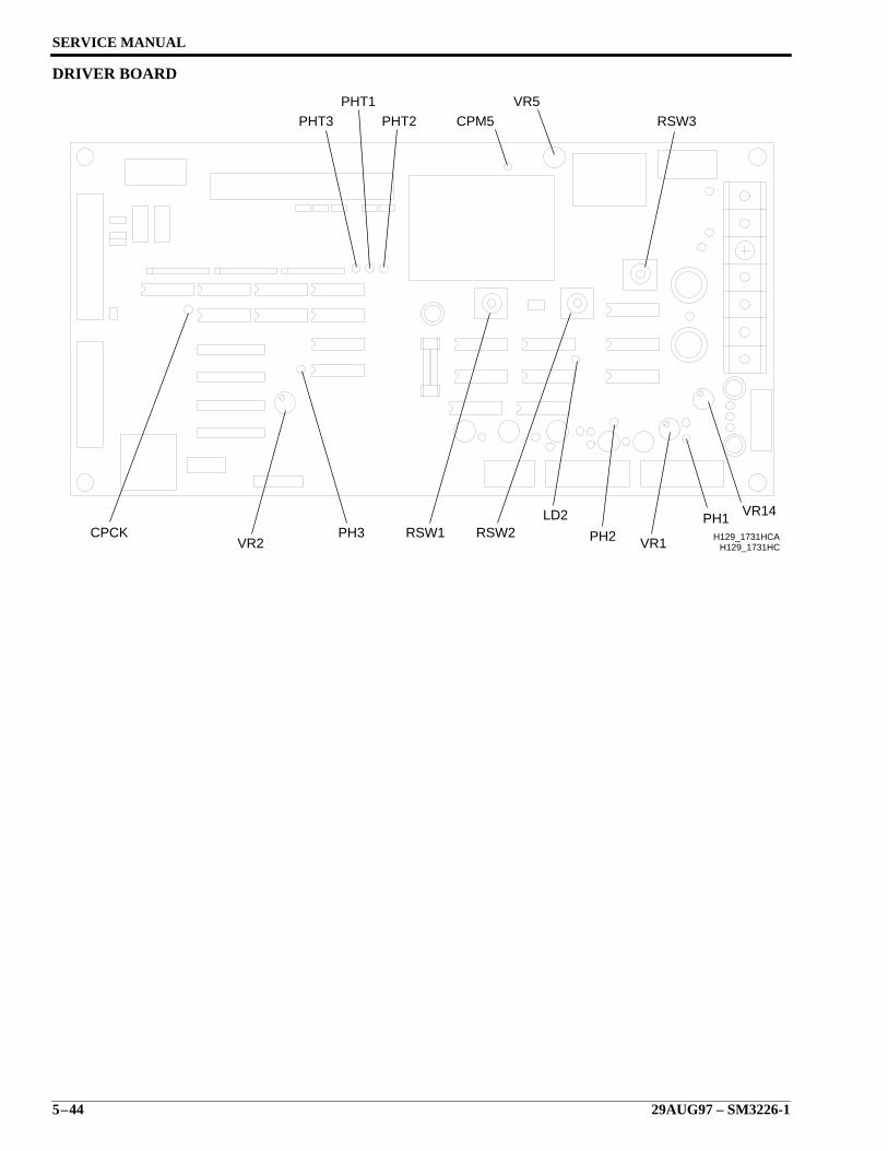
SERVICE MANUAL
5–44 29AUG97 – SM3226-1
DRIVER BOARD
H129_1731HC
RSW3
VR5
CPM5PHT2PHT3
PHT1
PH2RSW1 RSW2LD2
VR1
PH1 VR14
VR2PH3CPCK H129_1731HCA
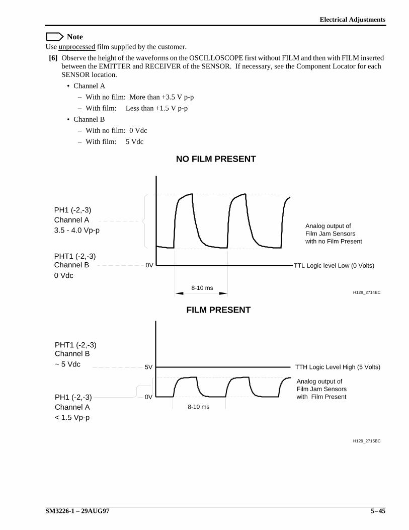
Electrical Adjustments
SM3226-1 – 29AUG97 5–45
NoteUse unprocessed film supplied by the customer.
[6] Observe the height of the waveforms on the OSCILLOSCOPE first without FILM and then with FILM insertedbetween the EMITTER and RECEIVER of the SENSOR. If necessary, see the Component Locator for eachSENSOR location.
• Channel A
– With no film: More than +3.5 V p-p
– With film: Less than +1.5 V p-p
• Channel B
– With no film: 0 Vdc
– With film: 5 Vdc
8-10 ms
Channel A
Channel B
PH1 (-2,-3)
3.5 - 4.0 Vp-p
0 Vdc
PHT1 (-2,-3)
NO FILM PRESENT
0V
H129_2714BC
Analog output ofFilm Jam Sensorswith no Film Present
TTL Logic level Low (0 Volts)
Channel A
Channel B
PH1 (-2,-3)
< 1.5 Vp-p
~ 5 Vdc
PHT1 (-2,-3)
FILM PRESENT
Analog output ofFilm Jam Sensorswith Film Present
TTH Logic Level High (5 Volts)
0V
8-10 ms
5V
H129_2715BC
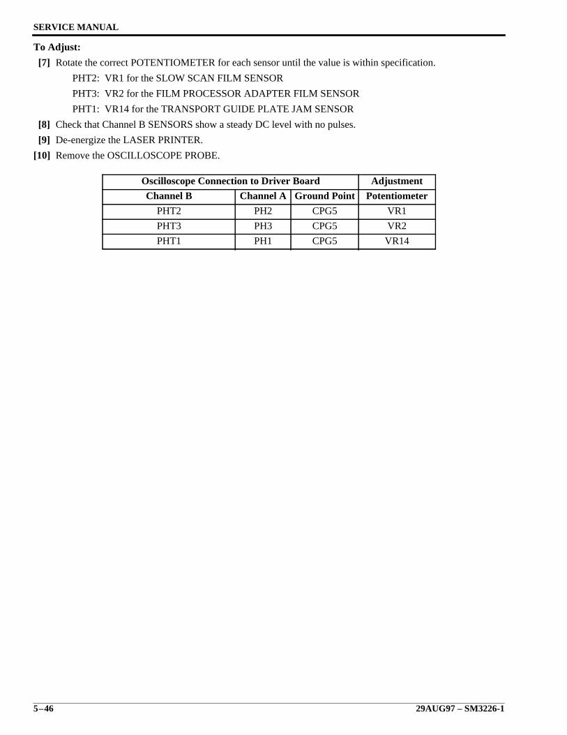
SERVICE MANUAL
5–46 29AUG97 – SM3226-1
To Adjust:
[7] Rotate the correct POTENTIOMETER for each sensor until the value is within specification.
PHT2: VR1 for the SLOW SCAN FILM SENSOR
PHT3: VR2 for the FILM PROCESSOR ADAPTER FILM SENSOR
PHT1: VR14 for the TRANSPORT GUIDE PLATE JAM SENSOR
[8] Check that Channel B SENSORS show a steady DC level with no pulses.
[9] De-energize the LASER PRINTER.
[10] Remove the OSCILLOSCOPE PROBE.
Oscilloscope Connection to Driver Board Adjustment
Channel B Channel A Ground Point Potentiometer
PHT2 PH2 CPG5 VR1
PHT3 PH3 CPG5 VR2
PHT1 PH1 CPG5 VR14
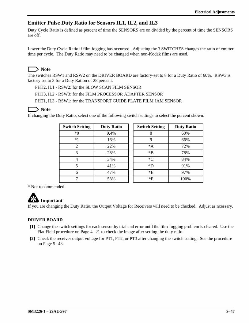
Electrical Adjustments
SM3226-1 – 29AUG97 5–47
Emitter Pulse Duty Ratio for Sensors IL1, IL2, and IL3Duty Cycle Ratio is defined as percent of time the SENSORS are on divided by the percent of time the SENSORSare off.
Lower the Duty Cycle Ratio if film fogging has occurred. Adjusting the 3 SWITCHES changes the ratio of emittertime per cycle. The Duty Ratio may need to be changed when non-Kodak films are used.
NoteThe switches RSW1 and RSW2 on the DRIVER BOARD are factory-set to 8 for a Duty Ratio of 60%. RSW3 isfactory set to 3 for a Duty Ration of 28 percent.
PHT2, IL1 - RSW2: for the SLOW SCAN FILM SENSOR
PHT3, IL2 - RSW3: for the FILM PROCESSOR ADAPTER SENSOR
PHT1, IL3 - RSW1: for the TRANSPORT GUIDE PLATE FILM JAM SENSOR
NoteIf changing the Duty Ratio, select one of the following switch settings to select the percent shown:
* Not recommended.
ImportantIf you are changing the Duty Ratio, the Output Voltage for Receivers will need to be checked. Adjust as ncessary.
DRIVER BOARD
[1] Change the switch settings for each sensor by trial and error until the film-fogging problem is cleared. Use theFlat Field procedure on Page 4–21 to check the image after setting the duty ratio.
[2] Check the receiver output voltage for PT1, PT2, or PT3 after changing the switch setting. See the procedureon Page 5–43.
Switch Setting Duty Ratio Switch Setting Duty Ratio
*0 9.4% 8 60%
*1 16% 9 66%
2 22% *A 72%
3 28% *B 78%
4 34% *C 84%
5 41% *D 91%
6 47% *E 97%
7 53% *F 100%
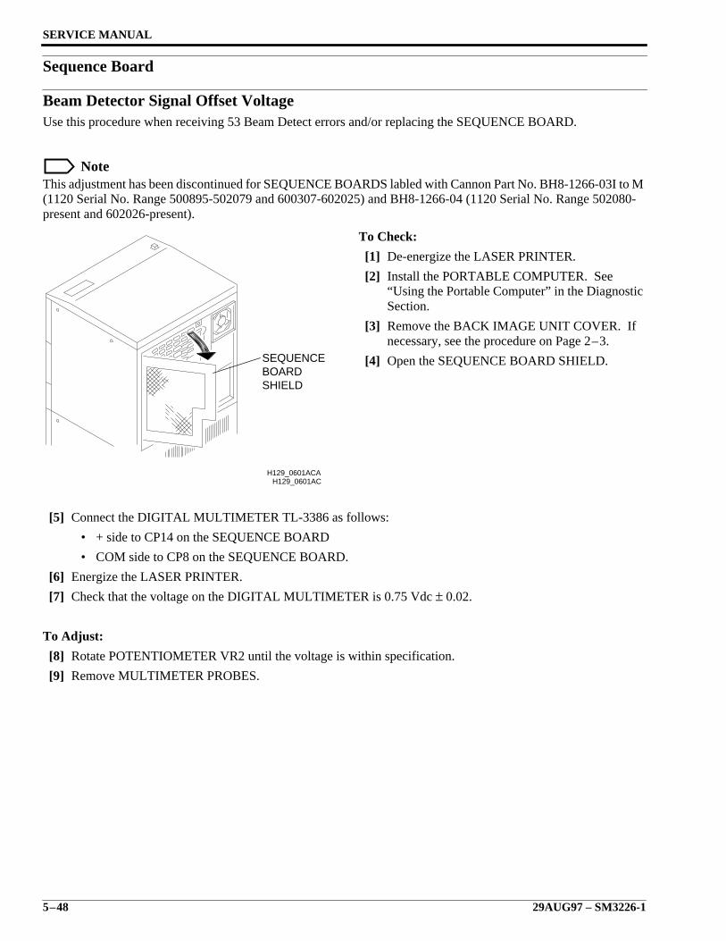
SERVICE MANUAL
5–48 29AUG97 – SM3226-1
Sequence Board
Beam Detector Signal Offset VoltageUse this procedure when receiving 53 Beam Detect errors and/or replacing the SEQUENCE BOARD.
NoteThis adjustment has been discontinued for SEQUENCE BOARDS labled with Cannon Part No. BH8-1266-03I to M(1120 Serial No. Range 500895-502079 and 600307-602025) and BH8-1266-04 (1120 Serial No. Range 502080-present and 602026-present).
To Check:
[1] De-energize the LASER PRINTER.
[2] Install the PORTABLE COMPUTER. See“Using the Portable Computer” in the DiagnosticSection.
[3] Remove the BACK IMAGE UNIT COVER. Ifnecessary, see the procedure on Page 2–3.
[4] Open the SEQUENCE BOARD SHIELD.
[5] Connect the DIGITAL MULTIMETER TL-3386 as follows:
• + side to CP14 on the SEQUENCE BOARD
• COM side to CP8 on the SEQUENCE BOARD.
[6] Energize the LASER PRINTER.
[7] Check that the voltage on the DIGITAL MULTIMETER is 0.75 Vdc ± 0.02.
To Adjust:
[8] Rotate POTENTIOMETER VR2 until the voltage is within specification.
[9] Remove MULTIMETER PROBES.
H129_0601AC
SHIELDBOARDSEQUENCE
H129_0601ACA
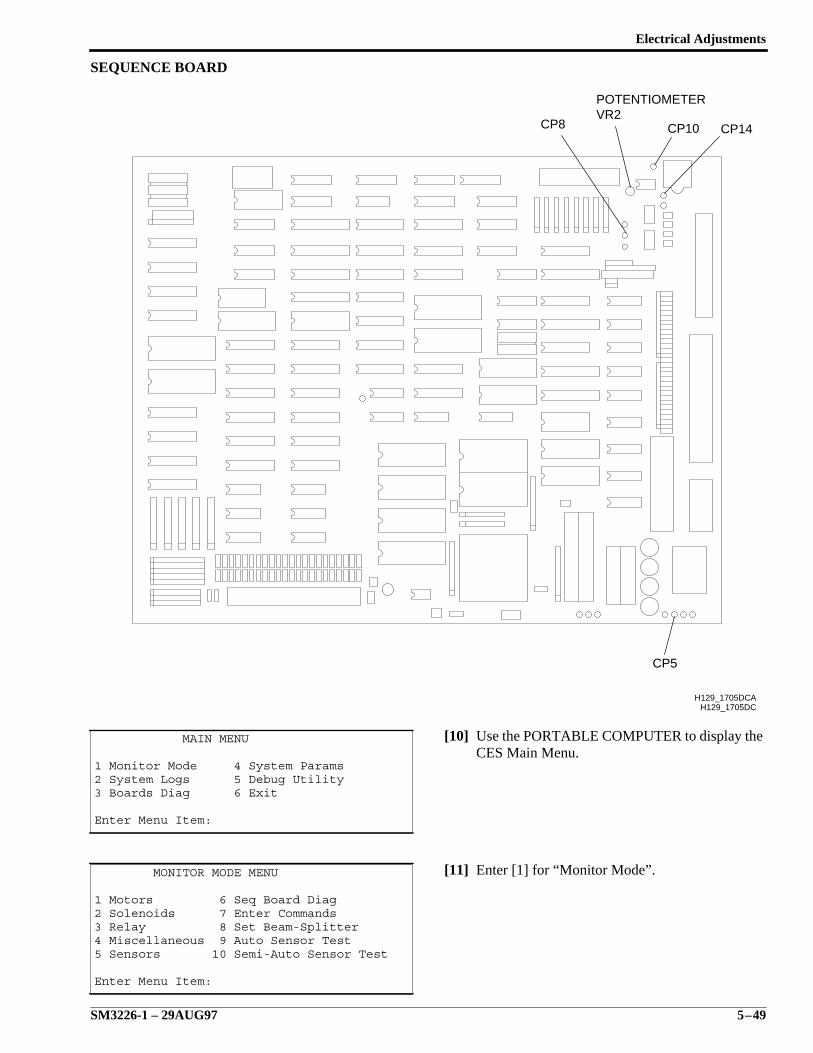
Electrical Adjustments
SM3226-1 – 29AUG97 5–49
SEQUENCE BOARD
[10] Use the PORTABLE COMPUTER to display theCES Main Menu.
[11] Enter [1] for “Monitor Mode”.
MAIN MENU
1 Monitor Mode 4 System Params2 System Logs 5 Debug Utility3 Boards Diag 6 Exit
Enter Menu Item:
MONITOR MODE MENU
1 Motors 6 Seq Board Diag2 Solenoids 7 Enter Commands3 Relay 8 Set Beam-Splitter4 Miscellaneous 9 Auto Sensor Test5 Sensors 10 Semi-Auto Sensor Test
Enter Menu Item:
H129_1705DC
CP5
CP8 CP10 CP14
POTENTIOMETERVR2
H129_1705DCA
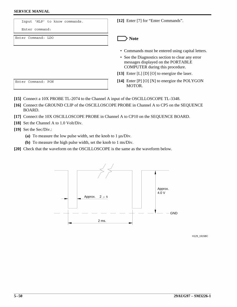
SERVICE MANUAL
5–50 29AUG97 – SM3226-1
[12] Enter [7] for “Enter Commands”.
Note
• Commands must be entered using capital letters.
• See the Diagnostics section to clear any errormessages displayed on the PORTABLECOMPUTER during this procedure.
[13] Enter [L] [D] [O] to energize the laser.
[14] Enter [P] [O] [N] to energize the POLYGONMOTOR.
[15] Connect a 10X PROBE TL-2074 to the Channel A input of the OSCILLOSCOPE TL-3348.
[16] Connect the GROUND CLIP of the OSCILLOSCOPE PROBE in Channel A to CP5 on the SEQUENCEBOARD.
[17] Connect the 10X OSCILLOSCOPE PROBE in Channel A to CP10 on the SEQUENCE BOARD.
[18] Set the Channel A to 1.0 Volt/Div.
[19] Set the Sec/Div.:
(a) To measure the low pulse width, set the knob to 1 µs/Div.
(b) To measure the high pulse width, set the knob to 1 ms/Div.
[20] Check that the waveform on the OSCILLOSCOPE is the same as the waveform below.
Input ‘HLP’ to know commands.
Enter command:
Enter Command: LDO
Enter Command: PON
2 ms.
Approx.4.0 V
GND
Approx. 2 s
H129_1915BC

Electrical Adjustments
SM3226-1 – 29AUG97 5–51
To Adjust:
[21] Rotate the POTENTIOMETER VR2 until thevoltage and waveform are correct.
[22] Enter [L] [D] [F] to turn off the Laser Diode.
[23] Enter [P] [O] [F] to turn off the Polygon Motor.
[24] Press [ESC] 3 times to exit diagnostics.
[25] Remove the OSCILLOSCOPE PROBE.
[26] Close the SEQUENCE BOARD SHIELDCOVER.
[27] Replace the BACK IMAGE UNIT COVER.
error=0Enter Command:LDF
error=0Enter Command:POF

SERVICE MANUAL
5–52 29AUG97 – SM3226-1
5-Phase Pulse Motor Boards for the Transport Motor Voltages (5PMD)Use this procedure after installing a new TRANSPORT ROLLER DRIVER BOARD, SUPPLY ROLLER DRIVERBOARD, or RECEIVE ROLLER DRIVER BOARD. The 3 FILM TRANSPORT MOTORS in the LASERPRINTER operate with the same type of circuit board, the 5-PHASE PULSE MOTOR BOARD.
NoteThere are four versions of the 5-Phase MOTOR BOARD. The version illustrated here contains checks andadjustments and may be interchanged between the TRANSPORT ROLLER DRIVER BOARD, SUPPLYROLLER DRIVER BOARD, and/or RECEIVE ROLLER DRIVER BOARD with correct adjustment. Thethree new versions contain no adjustments and are specific to each BOARD. They cannot be interchanged.Service Parts Management will stock the adjustable style for a universal approach.
To Check:
[1] Install the PORTABLE COMPUTER. See “Using the Portable Computer” in the Diagnostic Section.
[2] De-energize the LASER PRINTER.
[3] Remove the correct COVERS for the CIRCUIT BOARD being adjusted.
(a) Remove the TOP COVER for the TRANSPORT ROLLER DRIVER BOARD and RECEIVE ROLLERDRIVER BOARD.
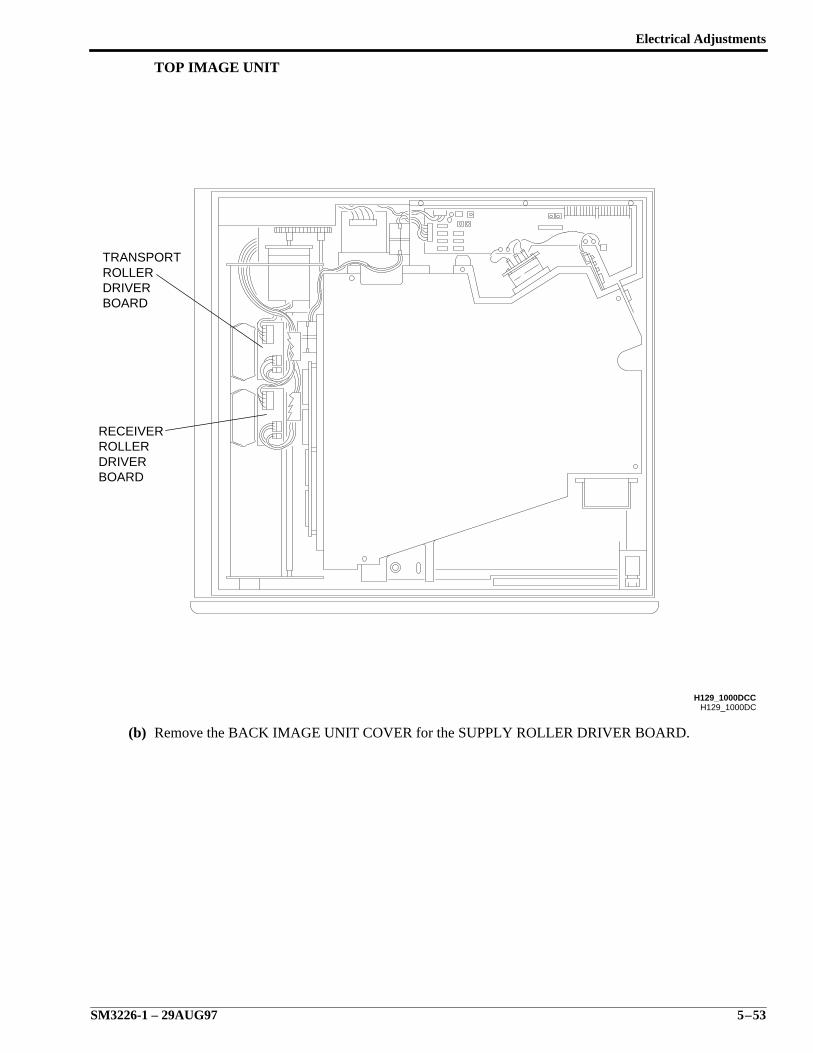
Electrical Adjustments
SM3226-1 – 29AUG97 5–53
TOP IMAGE UNIT
(b) Remove the BACK IMAGE UNIT COVER for the SUPPLY ROLLER DRIVER BOARD.
H129_1000DC
BOARDDRIVERROLLERRECEIVER
BOARDDRIVERROLLERTRANSPORT
H129_1000DCC
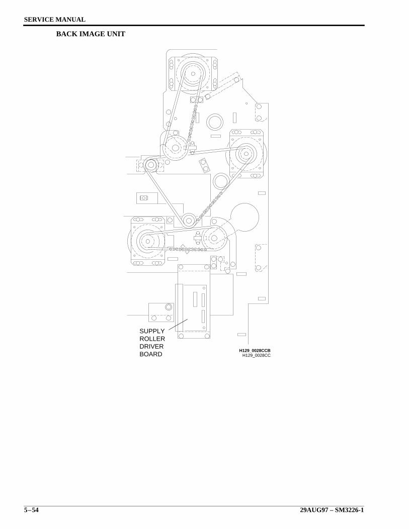
SERVICE MANUAL
5–54 29AUG97 – SM3226-1
BACK IMAGE UNIT
H129_0028CCBOARDDRIVERROLLERSUPPLY
H129_0028CCB
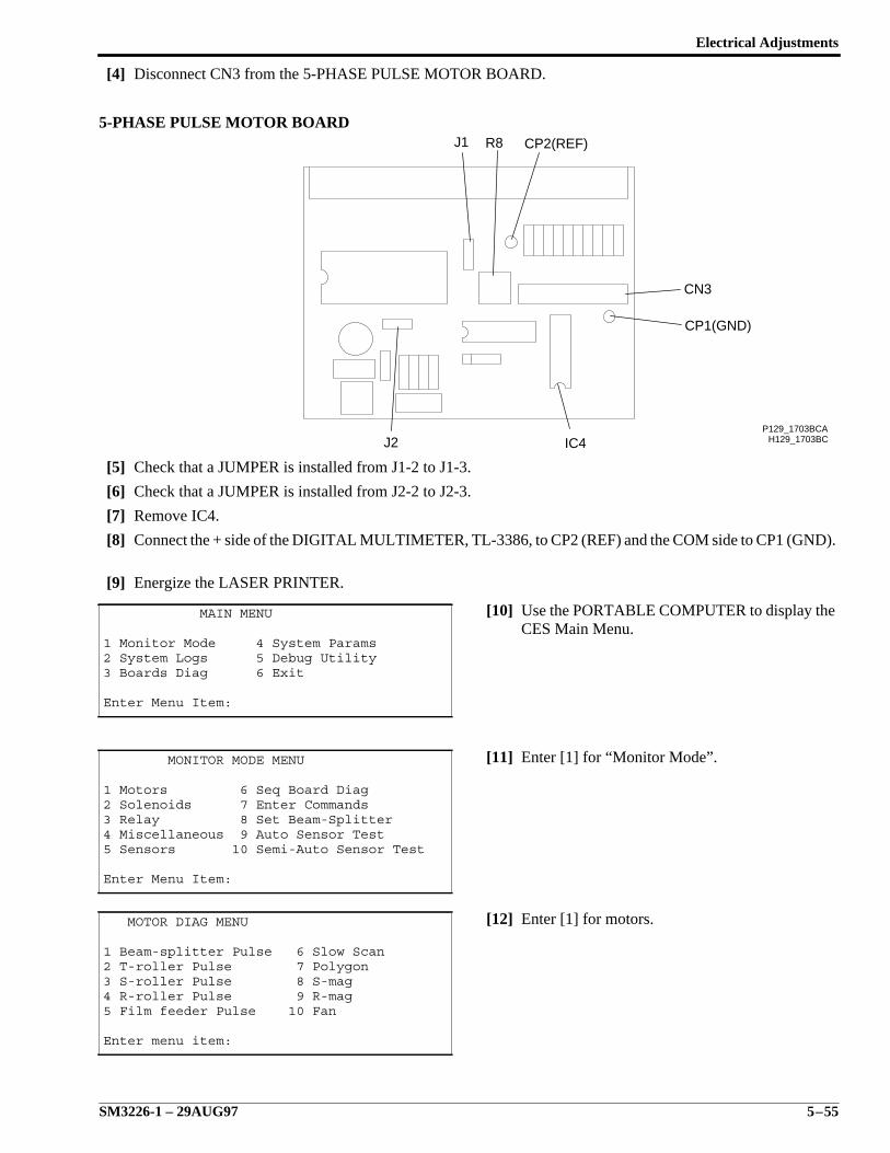
Electrical Adjustments
SM3226-1 – 29AUG97 5–55
[4] Disconnect CN3 from the 5-PHASE PULSE MOTOR BOARD.
5-PHASE PULSE MOTOR BOARD
[5] Check that a JUMPER is installed from J1-2 to J1-3.
[6] Check that a JUMPER is installed from J2-2 to J2-3.
[7] Remove IC4.
[8] Connect the + side of the DIGITAL MULTIMETER, TL-3386, to CP2 (REF) and the COM side to CP1 (GND).
[9] Energize the LASER PRINTER.
[10] Use the PORTABLE COMPUTER to display theCES Main Menu.
[11] Enter [1] for “Monitor Mode”.
[12] Enter [1] for motors.
MAIN MENU
1 Monitor Mode 4 System Params2 System Logs 5 Debug Utility3 Boards Diag 6 Exit
Enter Menu Item:
MONITOR MODE MENU
1 Motors 6 Seq Board Diag2 Solenoids 7 Enter Commands3 Relay 8 Set Beam-Splitter4 Miscellaneous 9 Auto Sensor Test5 Sensors 10 Semi-Auto Sensor Test
Enter Menu Item:
MOTOR DIAG MENU
1 Beam-splitter Pulse 6 Slow Scan2 T-roller Pulse 7 Polygon3 S-roller Pulse 8 S-mag4 R-roller Pulse 9 R-mag5 Film feeder Pulse 10 Fan
Enter menu item:
H129_1703BCP129_1703BCA
CP1(GND)
CP2(REF)R8
CN3
IC4J2
J1
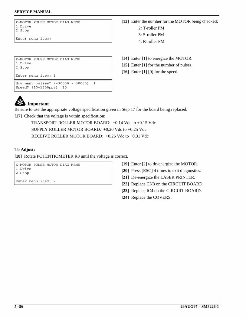
SERVICE MANUAL
5–56 29AUG97 – SM3226-1
[13] Enter the number for the MOTOR being checked:
2: T-roller PM
3: S-roller PM
4: R-roller PM
[14] Enter [1] to energize the MOTOR.
[15] Enter [1] for the number of pulses.
[16] Enter [1] [0] for the speed.
ImportantBe sure to use the appropriate voltage specification given in Step 17 for the board being replaced.
[17] Check that the voltage is within specification:
TRANSPORT ROLLER MOTOR BOARD: +0.14 Vdc to +0.15 Vdc
SUPPLY ROLLER MOTOR BOARD: +0.20 Vdc to +0.25 Vdc
RECEIVE ROLLER MOTOR BOARD: +0.26 Vdc to +0.31 Vdc
To Adjust:
[18] Rotate POTENTIOMETER R8 until the voltage is correct.
[19] Enter [2] to de-energize the MOTOR.
[20] Press [ESC] 4 times to exit diagnostics.
[21] De-energize the LASER PRINTER.
[22] Replace CN3 on the CIRCUIT BOARD.
[23] Replace IC4 on the CIRCUIT BOARD.
[24] Replace the COVERS.
X-MOTOR PULSE MOTOR DIAG MENU1 Drive2 Stop
Enter menu item:
X-MOTOR PULSE MOTOR DIAG MENU1 Drive2 Stop
Enter menu item: 1
How many pulses? (-30000 - 30000): 1Speed? (10-1500pps): 10
X-MOTOR PULSE MOTOR DIAG MENU1 Drive2 Stop
Enter menu item: 2
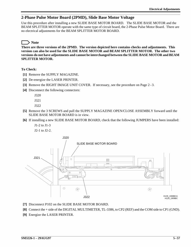
Electrical Adjustments
SM3226-1 – 29AUG97 5–57
2-Phase Pulse Motor Board (2PMD), Slide Base Motor VoltageUse this procedure after installing a new SLIDE BASE MOTOR BOARD. The SLIDE BASE MOTOR and theBEAM SPLITTER MOTOR operate with the same type of circuit board, the 2-Phase Pulse Motor Board. There areno electrical adjustments for the BEAM SPLITTER MOTOR BOARD.
NoteThere are three versions of the 2PMD. The version depicted here contains checks and adjustments. Thisversion can also be used for the SLIDE BASE MOTOR and BEAM SPLITTER MOTOR. The other twoversions do not have adjustments and cannot be interchanged between the SLIDE BASE MOTOR and BEAMSPLITTER MOTOR.
To Check:
[1] Remove the SUPPLY MAGAZINE.
[2] De-energize the LASER PRINTER.
[3] Remove the RIGHT IMAGE UNIT COVER. If necessary, see the procedure on Page 2–3.
[4] Disconnect the following connectors:
J320
J321
J322
[5] Remove the 3 SCREWS and pull the SUPPLY MAGAZINE OPEN/CLOSE ASSEMBLY forward until theSLIDE BASE MOTOR BOARD is in view.
[6] If installing a new SLIDE BASE MOTOR BOARD, check that the following JUMPERS have been installed:
J1-2 to J1-3
J2-1 to J2-2.
[7] Disconnect P102 on the SLIDE BASE MOTOR BOARD.
[8] Connect the + side of the DIGITAL MULTIMETER, TL-3386, to CP2 (REF) and the COM side to CP1 (GND).
[9] Energize the LASER PRINTER.
H129_1908BCJ322
J321
J320
SLIDE BASE MOTOR BOARD
H129_1908BCA
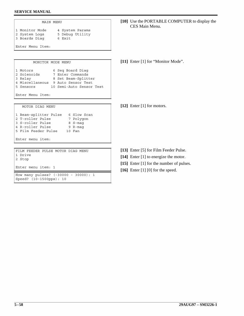
SERVICE MANUAL
5–58 29AUG97 – SM3226-1
[10] Use the PORTABLE COMPUTER to display theCES Main Menu.
[11] Enter [1] for “Monitor Mode”.
[12] Enter [1] for motors.
[13] Enter [5] for Film Feeder Pulse.
[14] Enter [1] to energize the motor.
[15] Enter [1] for the number of pulses.
[16] Enter [1] [0] for the speed.
MAIN MENU
1 Monitor Mode 4 System Params2 System Logs 5 Debug Utility3 Boards Diag 6 Exit
Enter Menu Item:
MONITOR MODE MENU
1 Motors 6 Seq Board Diag2 Solenoids 7 Enter Commands3 Relay 8 Set Beam-Splitter4 Miscellaneous 9 Auto Sensor Test5 Sensors 10 Semi-Auto Sensor Test
Enter Menu Item:
MOTOR DIAG MENU
1 Beam-splitter Pulse 6 Slow Scan2 T-roller Pulse 7 Polygon3 S-roller Pulse 8 S-mag4 R-roller Pulse 9 R-mag5 Film Feeder Pulse 10 Fan
Enter menu item:
FILM FEEDER PULSE MOTOR DIAG MENU1 Drive2 Stop
Enter menu item: 1
How many pulses? (-30000 - 30000): 1Speed? (10-1500pps): 10
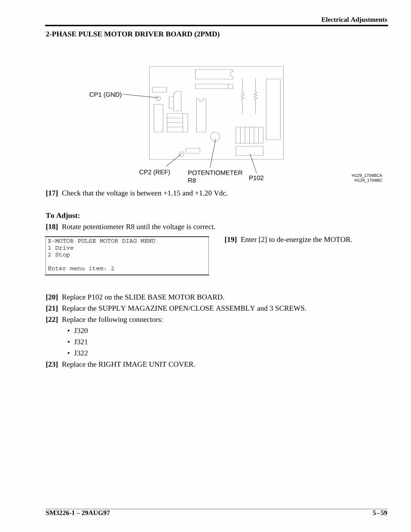
Electrical Adjustments
SM3226-1 – 29AUG97 5–59
2-PHASE PULSE MOTOR DRIVER BOARD (2PMD)
[17] Check that the voltage is between +1.15 and +1.20 Vdc.
To Adjust:
[18] Rotate potentiometer R8 until the voltage is correct.
[19] Enter [2] to de-energize the MOTOR.
[20] Replace P102 on the SLIDE BASE MOTOR BOARD.
[21] Replace the SUPPLY MAGAZINE OPEN/CLOSE ASSEMBLY and 3 SCREWS.
[22] Replace the following connectors:
• J320
• J321
• J322
[23] Replace the RIGHT IMAGE UNIT COVER.
X-MOTOR PULSE MOTOR DIAG MENU1 Drive2 Stop
Enter menu item: 2
H129_1704BCH129_1704BCAP102R8
POTENTIOMETERCP2 (REF)
CP1 (GND)
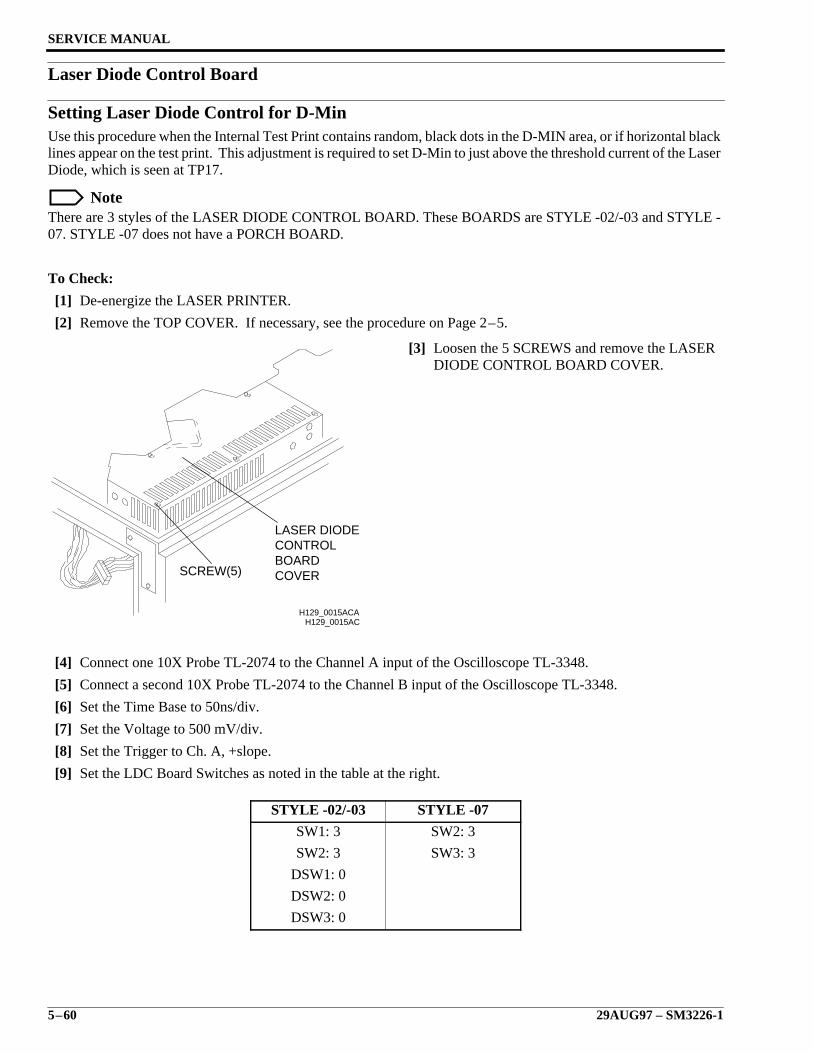
SERVICE MANUAL
5–60 29AUG97 – SM3226-1
Laser Diode Control Board
Setting Laser Diode Control for D-MinUse this procedure when the Internal Test Print contains random, black dots in the D-MIN area, or if horizontal blacklines appear on the test print. This adjustment is required to set D-Min to just above the threshold current of the LaserDiode, which is seen at TP17.
NoteThere are 3 styles of the LASER DIODE CONTROL BOARD. These BOARDS are STYLE -02/-03 and STYLE -07. STYLE -07 does not have a PORCH BOARD.
To Check:
[1] De-energize the LASER PRINTER.
[2] Remove the TOP COVER. If necessary, see the procedure on Page 2–5.
[3] Loosen the 5 SCREWS and remove the LASERDIODE CONTROL BOARD COVER.
[4] Connect one 10X Probe TL-2074 to the Channel A input of the Oscilloscope TL-3348.
[5] Connect a second 10X Probe TL-2074 to the Channel B input of the Oscilloscope TL-3348.
[6] Set the Time Base to 50ns/div.
[7] Set the Voltage to 500 mV/div.
[8] Set the Trigger to Ch. A, +slope.
[9] Set the LDC Board Switches as noted in the table at the right.
STYLE -02/-03 STYLE -07
SW1: 3 SW2: 3
SW2: 3 SW3: 3
DSW1: 0
DSW2: 0
DSW3: 0
H129_0015AC
COVERBOARDCONTROLLASER DIODE
SCREW(5)
H129_0015ACA
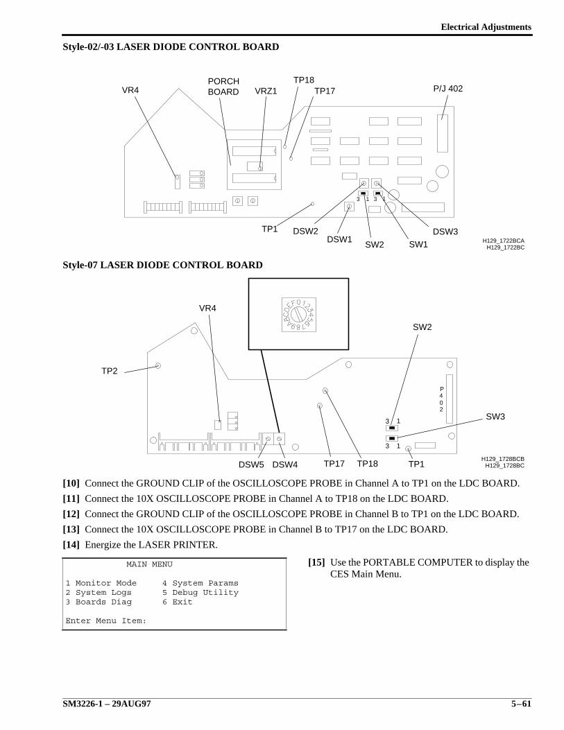
Electrical Adjustments
SM3226-1 – 29AUG97 5–61
Style-02/-03 LASER DIODE CONTROL BOARD
Style-07 LASER DIODE CONTROL BOARD
[10] Connect the GROUND CLIP of the OSCILLOSCOPE PROBE in Channel A to TP1 on the LDC BOARD.
[11] Connect the 10X OSCILLOSCOPE PROBE in Channel A to TP18 on the LDC BOARD.
[12] Connect the GROUND CLIP of the OSCILLOSCOPE PROBE in Channel B to TP1 on the LDC BOARD.
[13] Connect the 10X OSCILLOSCOPE PROBE in Channel B to TP17 on the LDC BOARD.
[14] Energize the LASER PRINTER.
[15] Use the PORTABLE COMPUTER to display theCES Main Menu.
MAIN MENU
1 Monitor Mode 4 System Params2 System Logs 5 Debug Utility3 Boards Diag 6 Exit
Enter Menu Item:
1313
H129_1722BC
VR4PORCHBOARD VRZ1
TP18TP17 P/J 402
TP1 DSW2DSW1
SW2 SW1
DSW3H129_1722BCA
3 1
3 1
P402
H129_1728BCDSW4DSW5
TP2
VR4
TP18TP17 TP1H129_1728BCB
SW3
SW2
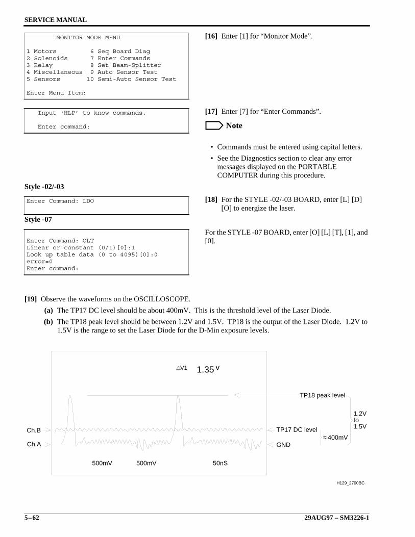
SERVICE MANUAL
5–62 29AUG97 – SM3226-1
[16] Enter [1] for “Monitor Mode”.
[17] Enter [7] for “Enter Commands”.
Note
• Commands must be entered using capital letters.
• See the Diagnostics section to clear any errormessages displayed on the PORTABLECOMPUTER during this procedure.
Style -02/-03
[18] For the STYLE -02/-03 BOARD, enter [L] [D][O] to energize the laser.
Style -07
For the STYLE -07 BOARD, enter [O] [L] [T], [1], and[0].
[19] Observe the waveforms on the OSCILLOSCOPE.
(a) The TP17 DC level should be about 400mV. This is the threshold level of the Laser Diode.
(b) The TP18 peak level should be between 1.2V and 1.5V. TP18 is the output of the Laser Diode. 1.2V to1.5V is the range to set the Laser Diode for the D-Min exposure levels.
MONITOR MODE MENU
1 Motors 6 Seq Board Diag2 Solenoids 7 Enter Commands3 Relay 8 Set Beam-Splitter4 Miscellaneous 9 Auto Sensor Test5 Sensors 10 Semi-Auto Sensor Test
Enter Menu Item:
Input ‘HLP’ to know commands.
Enter command:
Enter Command: LDO
Enter Command: OLTLinear or constant (0/1)[0]:1Look up table data (0 to 4095)[0]:0error=0Enter command:
1.5Vto1.2V
400mV~~
V1 v1.35
500mV 500mV 50nS
TP18 peak level
TP17 DC level
GND
Ch.B
Ch.A
H129_2700BC
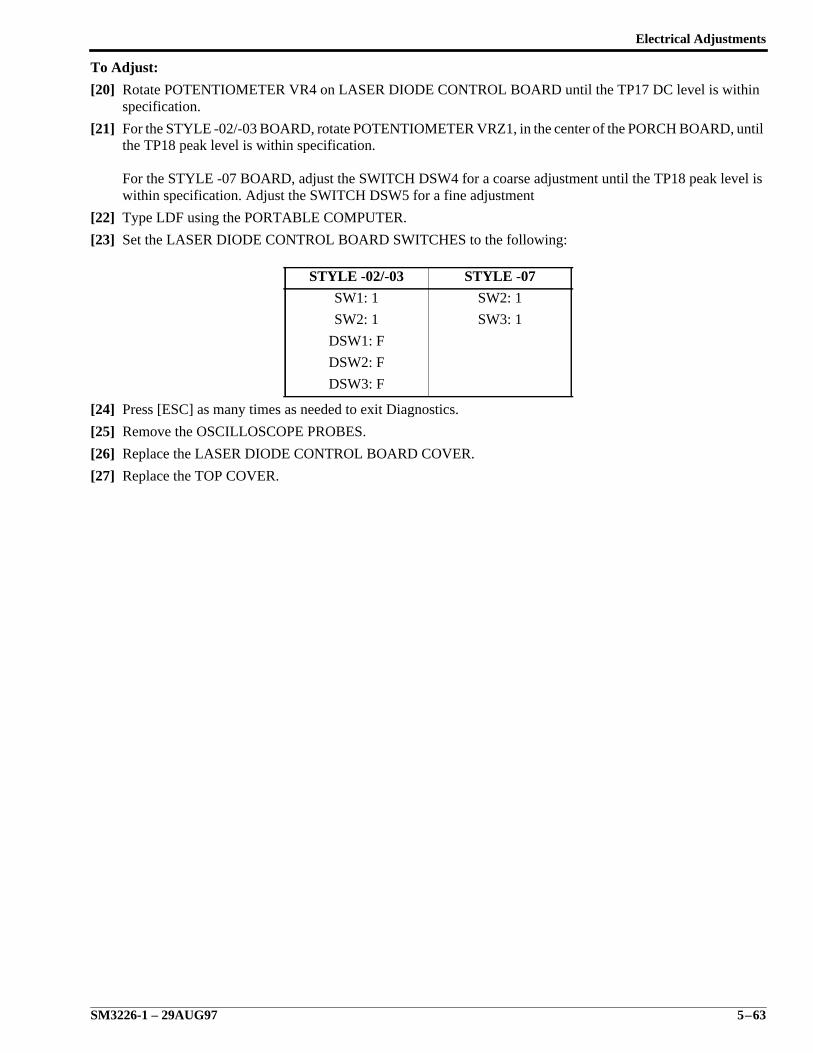
Electrical Adjustments
SM3226-1 – 29AUG97 5–63
To Adjust:
[20] Rotate POTENTIOMETER VR4 on LASER DIODE CONTROL BOARD until the TP17 DC level is withinspecification.
[21] For the STYLE -02/-03 BOARD, rotate POTENTIOMETER VRZ1, in the center of the PORCH BOARD, untilthe TP18 peak level is within specification.
For the STYLE -07 BOARD, adjust the SWITCH DSW4 for a coarse adjustment until the TP18 peak level iswithin specification. Adjust the SWITCH DSW5 for a fine adjustment
[22] Type LDF using the PORTABLE COMPUTER.
[23] Set the LASER DIODE CONTROL BOARD SWITCHES to the following:
[24] Press [ESC] as many times as needed to exit Diagnostics.
[25] Remove the OSCILLOSCOPE PROBES.
[26] Replace the LASER DIODE CONTROL BOARD COVER.
[27] Replace the TOP COVER.
STYLE -02/-03 STYLE -07
SW1: 1 SW2: 1
SW2: 1 SW3: 1
DSW1: F
DSW2: F
DSW3: F
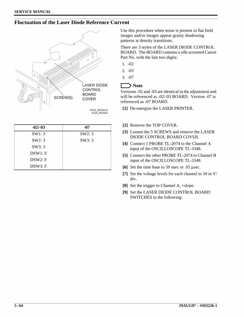
SERVICE MANUAL
5–64 29AUG97 – SM3226-1
Fluctuation of the Laser Diode Reference CurrentUse this procedure when noise is present in flat fieldimages and/or images appear grainy shadowingpatterns at density transitions.
There are 3 styles of the LASER DIODE CONTROLBOARD. The BOARD contains a silk-screened CanonPart No. with the last two digits:
1. -02
2. -03
3. -07
NoteVersions -02 and -03 are identical in the adjustment andwill be referenced as -02/-03 BOARD. Version -07 isreferenced as -07 BOARD.
[1] De-energize the LASER PRINTER.
[2] Remove the TOP COVER.
[3] Loosen the 5 SCREWS and remove the LASERDIODE CONTROL BOARD COVER.
[4] Connect 1 PROBE TL-2074 to the Channel Ainput of the OSCILLOSCOPE TL-3348.
[5] Connect the other PROBE TL-2074 to Channel Binput of the OSCILLOSCOPE TL-3348.
[6] Set the time base to 50 nsec or .05 µsec.
[7] Set the voltage levels for each channel to 50 m V/div.
[8] Set the trigger to Channel A, +slope.
[9] Set the LASER DIODE CONTROL BOARDSWITCHES to the following:
-02/-03 -07
SW1: 3 SW2: 3
SW2: 3 SW3: 3
SW3: 3
DSW1: F
DSW2: F
DSW3: F
H129_0015AC
COVERBOARDCONTROLLASER DIODE
SCREW(5)
H129_0015ACA
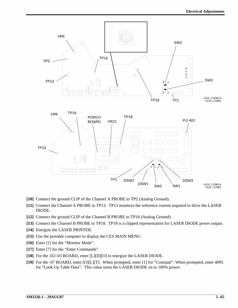
Electrical Adjustments
SM3226-1 – 29AUG97 5–65
[10] Connect the ground CLIP of the Channel A PROBE to TP2 (Analog Ground).
[11] Connect the Channel A PROBE to TP13. TP13 monitors the reference current required to drive the LASERDIODE.
[12] Connect the ground CLIP of the Channel B PROBE to TP16 (Analog Ground).
[13] Connect the Channel B PROBE to TP18. TP18 is a clipped representation for LASER DIODE power output.
[14] Energize the LASER PRINTER.
[15] Use the portable computer to display the CES MAIN MENU.
[16] Enter [1] for the “Monitor Mode”.
[17] Enter [7] for the “Enter Commands”.
[18] For the -02/-03 BOARD, enter [L][D][O] to energize the LASER DIODE.
[19] For the -07 BOARD, enter [O][L][T]. When prompted, enter [1] for “Constant”. When prompted, enter 4095for “Look Up Table Data”. This value turns the LASER DIODE on to 100% power.
H129_1730BC
204P
13
13
H129_1730BCA
TP16
VR6
TP13
SW2
SW3
TP1TP18
TP2
H129_1729BC
3 1 3 1
H129_1729BCA
TP16VR6
TP13
PORCHBOARD VRZ1
TP18P/J 402
TP1 DSW2DSW1
SW2 SW1
DSW3
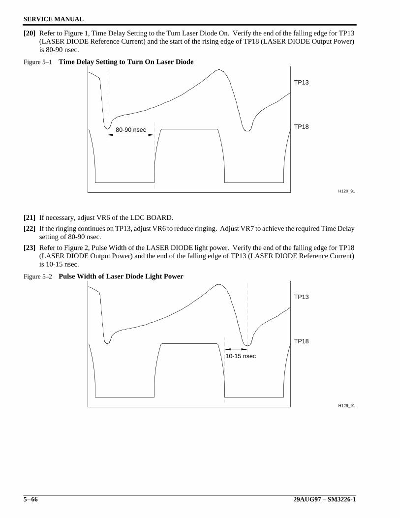
SERVICE MANUAL
5–66 29AUG97 – SM3226-1
[20] Refer to Figure 1, Time Delay Setting to the Turn Laser Diode On. Verify the end of the falling edge for TP13(LASER DIODE Reference Current) and the start of the rising edge of TP18 (LASER DIODE Output Power)is 80-90 nsec.
Figure 5–1 Time Delay Setting to Turn On Laser Diode
[21] If necessary, adjust VR6 of the LDC BOARD.
[22] If the ringing continues on TP13, adjust VR6 to reduce ringing. Adjust VR7 to achieve the required Time Delaysetting of 80-90 nsec.
[23] Refer to Figure 2, Pulse Width of the LASER DIODE light power. Verify the end of the falling edge for TP18(LASER DIODE Output Power) and the end of the falling edge of TP13 (LASER DIODE Reference Current)is 10-15 nsec.
Figure 5–2 Pulse Width of Laser Diode Light Power
TP18
TP13
80-90 nsec
H129_911
10-15 nsec
H129_911
TP13
TP18
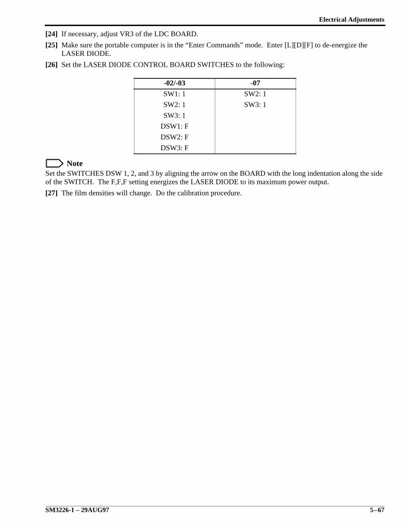
Electrical Adjustments
SM3226-1 – 29AUG97 5–67
[24] If necessary, adjust VR3 of the LDC BOARD.
[25] Make sure the portable computer is in the “Enter Commands” mode. Enter [L][D][F] to de-energize theLASER DIODE.
[26] Set the LASER DIODE CONTROL BOARD SWITCHES to the following:
NoteSet the SWITCHES DSW 1, 2, and 3 by aligning the arrow on the BOARD with the long indentation along the sideof the SWITCH. The F,F,F setting energizes the LASER DIODE to its maximum power output.
[27] The film densities will change. Do the calibration procedure.
-02/-03 -07
SW1: 1 SW2: 1
SW2: 1 SW3: 1
SW3: 1
DSW1: F
DSW2: F
DSW3: F
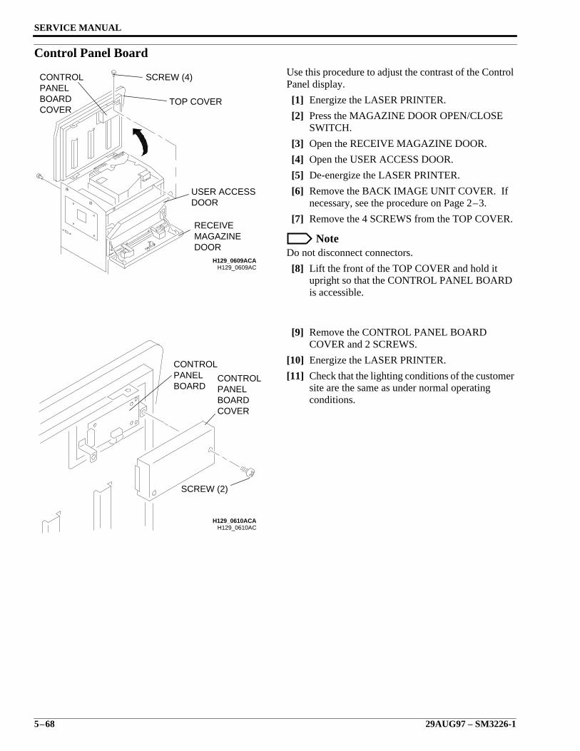
SERVICE MANUAL
5–68 29AUG97 – SM3226-1
Control Panel BoardUse this procedure to adjust the contrast of the ControlPanel display.
[1] Energize the LASER PRINTER.
[2] Press the MAGAZINE DOOR OPEN/CLOSESWITCH.
[3] Open the RECEIVE MAGAZINE DOOR.
[4] Open the USER ACCESS DOOR.
[5] De-energize the LASER PRINTER.
[6] Remove the BACK IMAGE UNIT COVER. Ifnecessary, see the procedure on Page 2–3.
[7] Remove the 4 SCREWS from the TOP COVER.
NoteDo not disconnect connectors.
[8] Lift the front of the TOP COVER and hold itupright so that the CONTROL PANEL BOARDis accessible.
[9] Remove the CONTROL PANEL BOARDCOVER and 2 SCREWS.
[10] Energize the LASER PRINTER.
[11] Check that the lighting conditions of the customersite are the same as under normal operatingconditions.
H129_0609ACH129_0609ACA
SCREW (4)
TOP COVER
USER ACCESSDOOR
RECEIVEMAGAZINEDOOR
CONTROLPANELBOARDCOVER
H129_0610AC
COVERBOARDPANELCONTROL
BOARDPANELCONTROL
H129_0610ACA
SCREW (2)
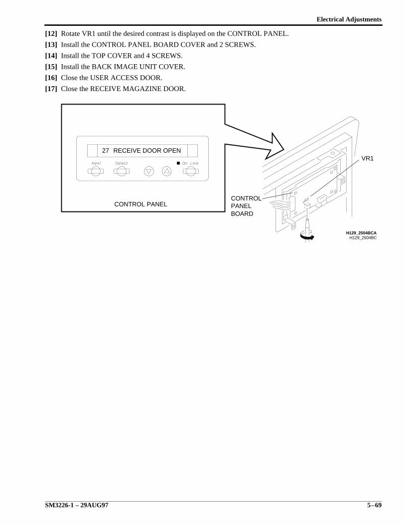
Electrical Adjustments
SM3226-1 – 29AUG97 5–69
[12] Rotate VR1 until the desired contrast is displayed on the CONTROL PANEL.
[13] Install the CONTROL PANEL BOARD COVER and 2 SCREWS.
[14] Install the TOP COVER and 4 SCREWS.
[15] Install the BACK IMAGE UNIT COVER.
[16] Close the USER ACCESS DOOR.
[17] Close the RECEIVE MAGAZINE DOOR.
H129_2504BC
27 RECEIVE DOOR OPEN
H129_2504BCA
VR1
CONTROLPANELBOARD
CONTROL PANEL
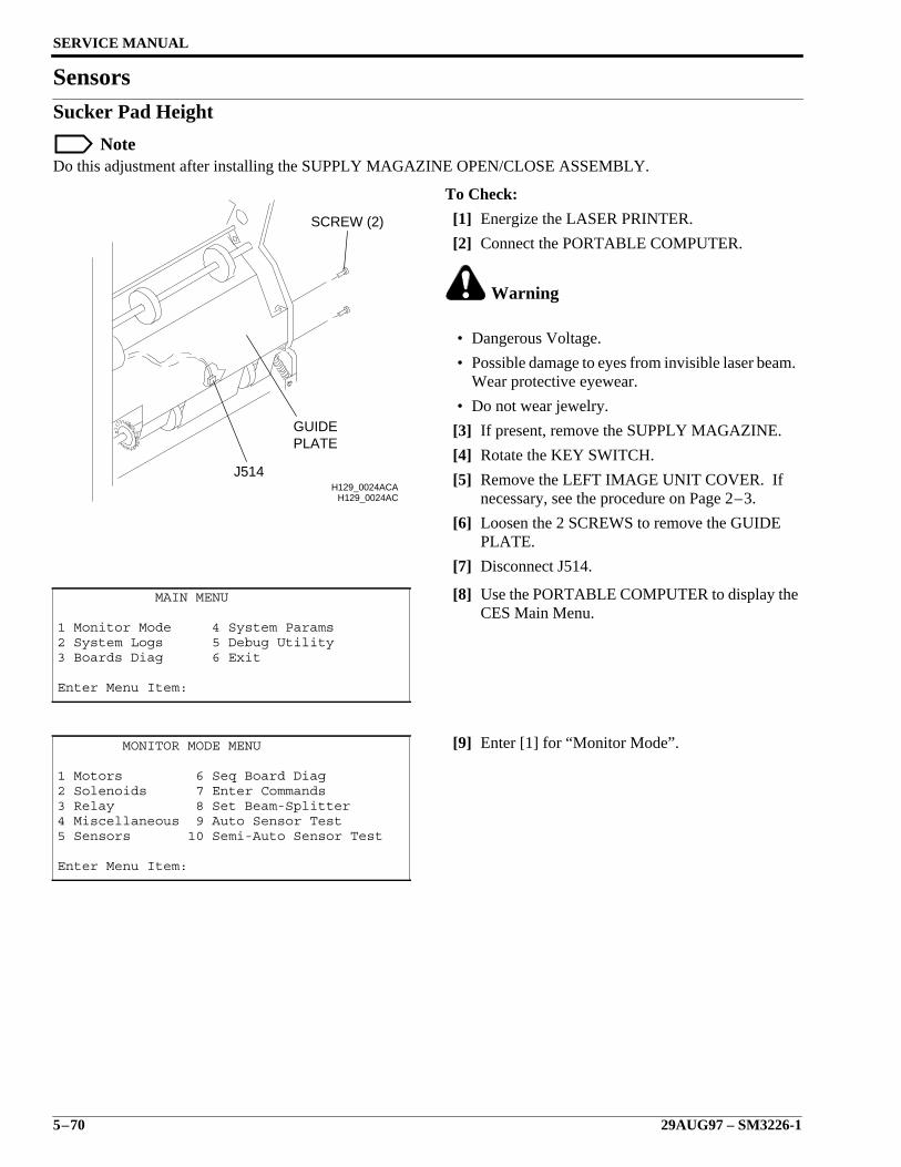
SERVICE MANUAL
5–70 29AUG97 – SM3226-1
SensorsSucker Pad Height
NoteDo this adjustment after installing the SUPPLY MAGAZINE OPEN/CLOSE ASSEMBLY.
To Check:
[1] Energize the LASER PRINTER.
[2] Connect the PORTABLE COMPUTER.
Warning
• Dangerous Voltage.
• Possible damage to eyes from invisible laser beam.Wear protective eyewear.
• Do not wear jewelry.
[3] If present, remove the SUPPLY MAGAZINE.
[4] Rotate the KEY SWITCH.
[5] Remove the LEFT IMAGE UNIT COVER. Ifnecessary, see the procedure on Page 2–3.
[6] Loosen the 2 SCREWS to remove the GUIDEPLATE.
[7] Disconnect J514.
[8] Use the PORTABLE COMPUTER to display theCES Main Menu.
[9] Enter [1] for “Monitor Mode”.
MAIN MENU
1 Monitor Mode 4 System Params2 System Logs 5 Debug Utility3 Boards Diag 6 Exit
Enter Menu Item:
MONITOR MODE MENU
1 Motors 6 Seq Board Diag2 Solenoids 7 Enter Commands3 Relay 8 Set Beam-Splitter4 Miscellaneous 9 Auto Sensor Test5 Sensors 10 Semi-Auto Sensor Test
Enter Menu Item:
H129_0024ACH129_0024ACA
J514
PLATEGUIDE
SCREW (2)
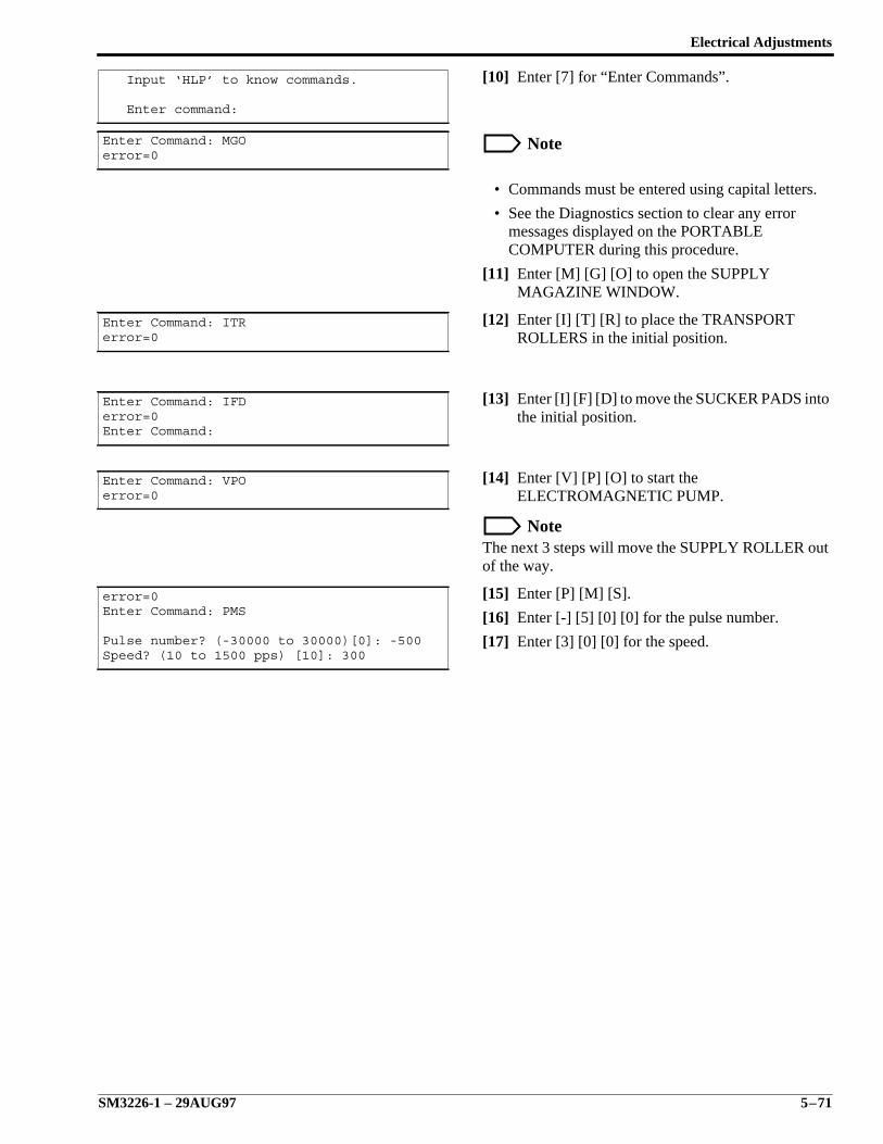
Electrical Adjustments
SM3226-1 – 29AUG97 5–71
[10] Enter [7] for “Enter Commands”.
Note
• Commands must be entered using capital letters.
• See the Diagnostics section to clear any errormessages displayed on the PORTABLECOMPUTER during this procedure.
[11] Enter [M] [G] [O] to open the SUPPLYMAGAZINE WINDOW.
[12] Enter [I] [T] [R] to place the TRANSPORTROLLERS in the initial position.
[13] Enter [I] [F] [D] to move the SUCKER PADS intothe initial position.
[14] Enter [V] [P] [O] to start theELECTROMAGNETIC PUMP.
NoteThe next 3 steps will move the SUPPLY ROLLER outof the way.
[15] Enter [P] [M] [S].
[16] Enter [-] [5] [0] [0] for the pulse number.
[17] Enter [3] [0] [0] for the speed.
Input ‘HLP’ to know commands.
Enter command:
Enter Command: MGOerror=0
Enter Command: ITRerror=0
Enter Command: IFDerror=0Enter Command:
Enter Command: VPOerror=0
error=0Enter Command: PMS
Pulse number? (-30000 to 30000)[0]: -500Speed? (10 to 1500 pps) [10]: 300

SERVICE MANUAL
5–72 29AUG97 – SM3226-1
[18] Press the PLASTIC RULER against the SUCKER PADS.
[19] Use the RULER to measure the distance between the PLASTIC RULER and the ROLLER. The distanceshould be 3-5 mm (0.12-0.20 in.).
[20] Enter VPF to turn the ELECTROMAGNETIC PUMP off.
H129_5400DC
SUCKERPAD
ROLLERPLASTICRULER
3-5 mm
H129_5400DCA
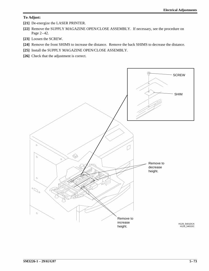
Electrical Adjustments
SM3226-1 – 29AUG97 5–73
To Adjust:
[21] De-energize the LASER PRINTER.
[22] Remove the SUPPLY MAGAZINE OPEN/CLOSE ASSEMBLY. If necessary, see the procedure onPage 2–42.
[23] Loosen the SCREW.
[24] Remove the front SHIMS to increase the distance. Remove the back SHIMS to decrease the distance.
[25] Install the SUPPLY MAGAZINE OPEN/CLOSE ASSEMBLY.
[26] Check that the adjustment is correct.
H129_5401DCH129_5401DCA
height.increaseRemove to
height.decreaseRemove to
SHIM
SCREW
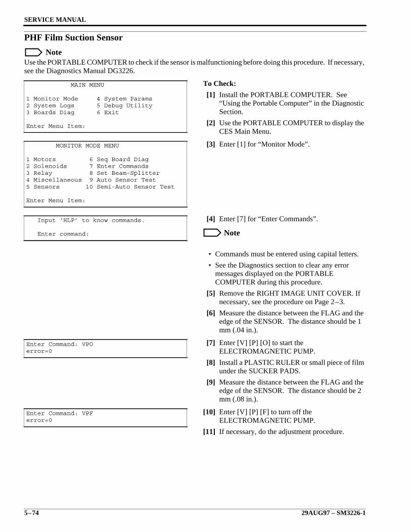
SERVICE MANUAL
5–74 29AUG97 – SM3226-1
PHF Film Suction Sensor
NoteUse the PORTABLE COMPUTER to check if the sensor is malfunctioning before doing this procedure. If necessary,see the Diagnostics Manual DG3226.
To Check:
[1] Install the PORTABLE COMPUTER. See“Using the Portable Computer” in the DiagnosticSection.
[2] Use the PORTABLE COMPUTER to display theCES Main Menu.
[3] Enter [1] for “Monitor Mode”.
[4] Enter [7] for “Enter Commands”.
Note
• Commands must be entered using capital letters.
• See the Diagnostics section to clear any errormessages displayed on the PORTABLECOMPUTER during this procedure.
[5] Remove the RIGHT IMAGE UNIT COVER. Ifnecessary, see the procedure on Page 2–3.
[6] Measure the distance between the FLAG and theedge of the SENSOR. The distance should be 1mm (.04 in.).
[7] Enter [V] [P] [O] to start theELECTROMAGNETIC PUMP.
[8] Install a PLASTIC RULER or small piece of filmunder the SUCKER PADS.
[9] Measure the distance between the FLAG and theedge of the SENSOR. The distance should be 2mm (.08 in.).
[10] Enter [V] [P] [F] to turn off theELECTROMAGNETIC PUMP.
[11] If necessary, do the adjustment procedure.
MAIN MENU
1 Monitor Mode 4 System Params2 System Logs 5 Debug Utility3 Boards Diag 6 Exit
Enter Menu Item:
MONITOR MODE MENU
1 Motors 6 Seq Board Diag2 Solenoids 7 Enter Commands3 Relay 8 Set Beam-Splitter4 Miscellaneous 9 Auto Sensor Test5 Sensors 10 Semi-Auto Sensor Test
Enter Menu Item:
Input ‘HLP’ to know commands.
Enter command:
Enter Command: VPOerror=0
Enter Command: VPFerror=0
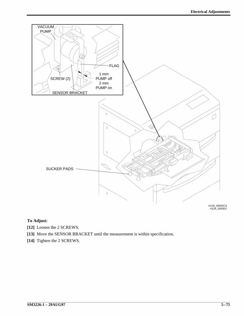
Electrical Adjustments
SM3226-1 – 29AUG97 5–75
To Adjust:
[12] Loosen the 2 SCREWS.
[13] Move the SENSOR BRACKET until the measurement is within specification.
[14] Tighten the 2 SCREWS.
H129_2600DCH129_2600DCA
SUCKER PADS
PUMP on2 mm
PUMP off1 mm
SENSOR BRACKET
SCREW (2)
FLAG
PUMPVACUUM
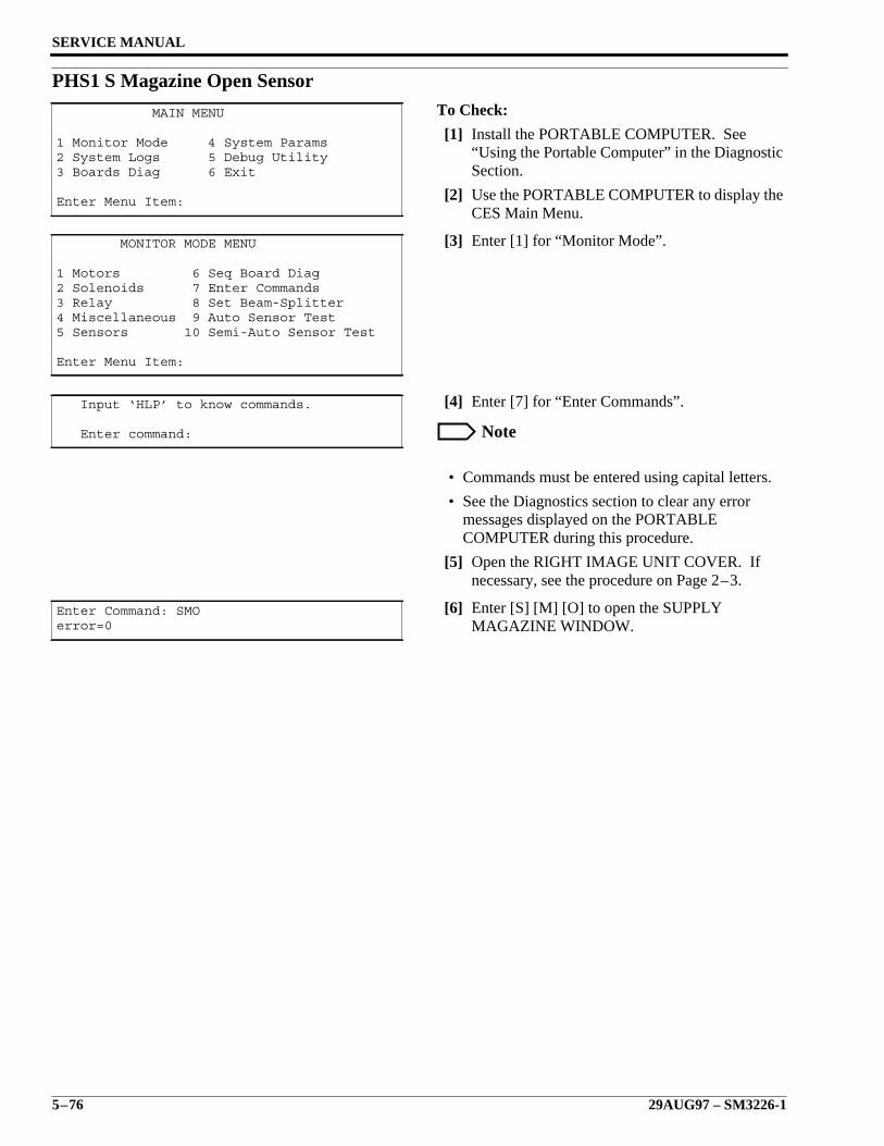
SERVICE MANUAL
5–76 29AUG97 – SM3226-1
PHS1 S Magazine Open SensorTo Check:
[1] Install the PORTABLE COMPUTER. See“Using the Portable Computer” in the DiagnosticSection.
[2] Use the PORTABLE COMPUTER to display theCES Main Menu.
[3] Enter [1] for “Monitor Mode”.
[4] Enter [7] for “Enter Commands”.
Note
• Commands must be entered using capital letters.
• See the Diagnostics section to clear any errormessages displayed on the PORTABLECOMPUTER during this procedure.
[5] Open the RIGHT IMAGE UNIT COVER. Ifnecessary, see the procedure on Page 2–3.
[6] Enter [S] [M] [O] to open the SUPPLYMAGAZINE WINDOW.
MAIN MENU
1 Monitor Mode 4 System Params2 System Logs 5 Debug Utility3 Boards Diag 6 Exit
Enter Menu Item:
MONITOR MODE MENU
1 Motors 6 Seq Board Diag2 Solenoids 7 Enter Commands3 Relay 8 Set Beam-Splitter4 Miscellaneous 9 Auto Sensor Test5 Sensors 10 Semi-Auto Sensor Test
Enter Menu Item:
Input ‘HLP’ to know commands.
Enter command:
Enter Command: SMOerror=0
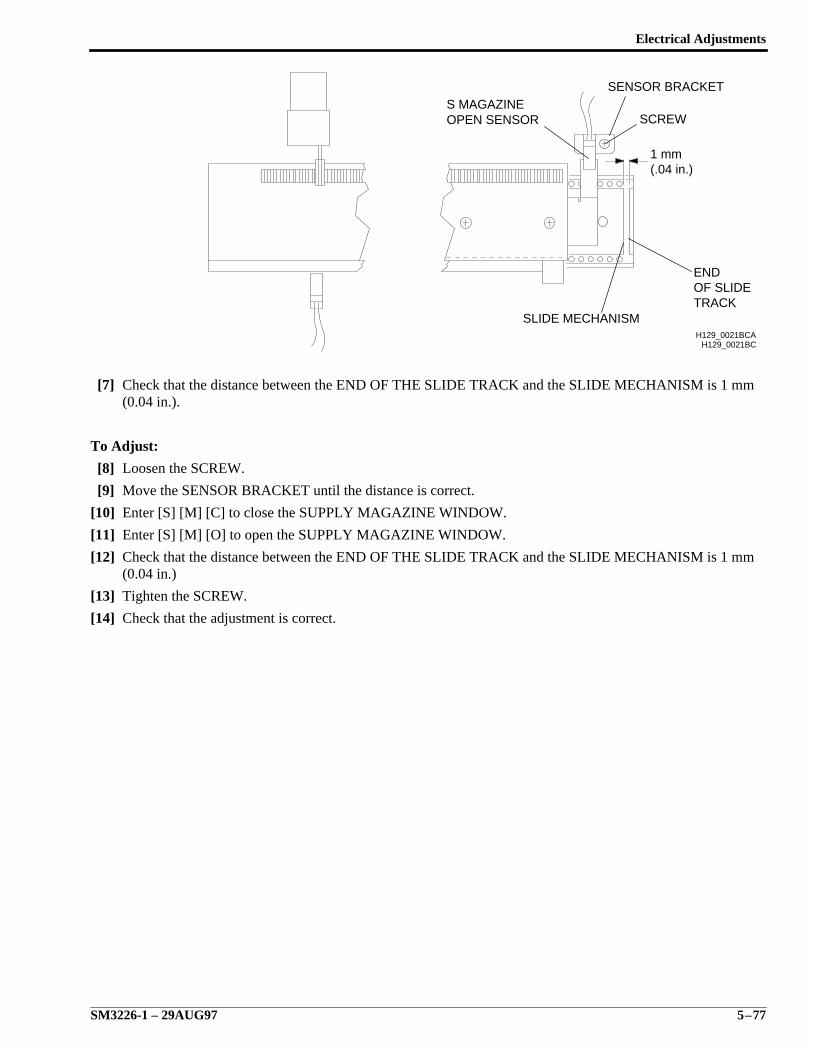
Electrical Adjustments
SM3226-1 – 29AUG97 5–77
[7] Check that the distance between the END OF THE SLIDE TRACK and the SLIDE MECHANISM is 1 mm(0.04 in.).
To Adjust:
[8] Loosen the SCREW.
[9] Move the SENSOR BRACKET until the distance is correct.
[10] Enter [S] [M] [C] to close the SUPPLY MAGAZINE WINDOW.
[11] Enter [S] [M] [O] to open the SUPPLY MAGAZINE WINDOW.
[12] Check that the distance between the END OF THE SLIDE TRACK and the SLIDE MECHANISM is 1 mm(0.04 in.)
[13] Tighten the SCREW.
[14] Check that the adjustment is correct.
H129_0021BC
TRACKOF SLIDE END
H129_0021BCA
(.04 in.)1 mm
SCREW
SENSOR BRACKET
SLIDE MECHANISM
OPEN SENSORS MAGAZINE
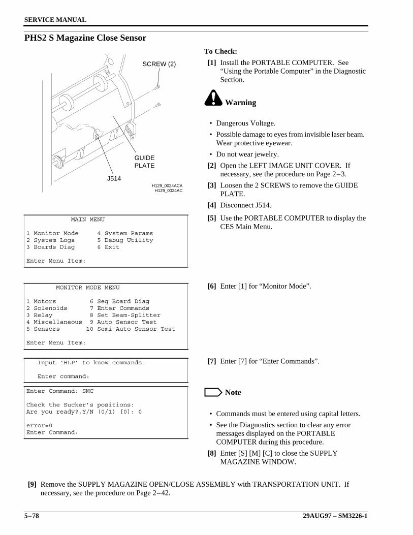
SERVICE MANUAL
5–78 29AUG97 – SM3226-1
PHS2 S Magazine Close SensorTo Check:
[1] Install the PORTABLE COMPUTER. See“Using the Portable Computer” in the DiagnosticSection.
Warning
• Dangerous Voltage.
• Possible damage to eyes from invisible laser beam.Wear protective eyewear.
• Do not wear jewelry.
[2] Open the LEFT IMAGE UNIT COVER. Ifnecessary, see the procedure on Page 2–3.
[3] Loosen the 2 SCREWS to remove the GUIDEPLATE.
[4] Disconnect J514.
[5] Use the PORTABLE COMPUTER to display theCES Main Menu.
[6] Enter [1] for “Monitor Mode”.
[7] Enter [7] for “Enter Commands”.
Note
• Commands must be entered using capital letters.
• See the Diagnostics section to clear any errormessages displayed on the PORTABLECOMPUTER during this procedure.
[8] Enter [S] [M] [C] to close the SUPPLYMAGAZINE WINDOW.
[9] Remove the SUPPLY MAGAZINE OPEN/CLOSE ASSEMBLY with TRANSPORTATION UNIT. Ifnecessary, see the procedure on Page 2–42.
MAIN MENU
1 Monitor Mode 4 System Params2 System Logs 5 Debug Utility3 Boards Diag 6 Exit
Enter Menu Item:
MONITOR MODE MENU
1 Motors 6 Seq Board Diag2 Solenoids 7 Enter Commands3 Relay 8 Set Beam-Splitter4 Miscellaneous 9 Auto Sensor Test5 Sensors 10 Semi-Auto Sensor Test
Enter Menu Item:
Input ‘HLP’ to know commands.
Enter command:
Enter Command: SMC
Check the Sucker’s positions:Are you ready?,Y/N (0/1) [0]: 0
error=0Enter Command:
H129_0024ACH129_0024ACA
J514
PLATEGUIDE
SCREW (2)
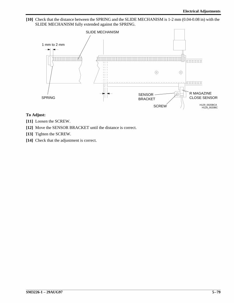
Electrical Adjustments
SM3226-1 – 29AUG97 5–79
[10] Check that the distance between the SPRING and the SLIDE MECHANISM is 1-2 mm (0.04-0.08 in) with theSLIDE MECHANISM fully extended against the SPRING.
To Adjust:
[11] Loosen the SCREW.
[12] Move the SENSOR BRACKET until the distance is correct.
[13] Tighten the SCREW.
[14] Check that the adjustment is correct.
H129_0020BCH129_0020BCA
R MAGAZINECLOSE SENSOR
SCREW
SENSORBRACKETSPRING
1 mm to 2 mm
SLIDE MECHANISM
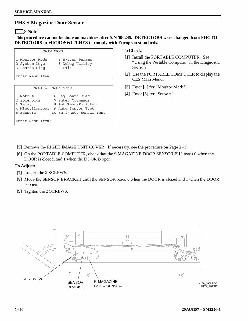
SERVICE MANUAL
5–80 29AUG97 – SM3226-1
PH3 S Magazine Door Sensor
NoteThis procedure cannot be done on machines after S/N 500249. DETECTORS were changed from PHOTODETECTORS to MICROSWITCHES to comply with European standards.
To Check:
[1] Install the PORTABLE COMPUTER. See“Using the Portable Computer” in the DiagnosticSection.
[2] Use the PORTABLE COMPUTER to display theCES Main Menu.
[3] Enter [1] for “Monitor Mode”.
[4] Enter [5] for “Sensors”.
[5] Remove the RIGHT IMAGE UNIT COVER. If necessary, see the procedure on Page 2–3.
[6] On the PORTABLE COMPUTER, check that the S MAGAZINE DOOR SENSOR PH3 reads 0 when theDOOR is closed, and 1 when the DOOR is open.
To Adjust:
[7] Loosen the 2 SCREWS.
[8] Move the SENSOR BRACKET until the SENSOR reads 0 when the DOOR is closed and 1 when the DOORis open.
[9] Tighten the 2 SCREWS.
MAIN MENU
1 Monitor Mode 4 System Params2 System Logs 5 Debug Utility3 Boards Diag 6 Exit
Enter Menu Item:
MONITOR MODE MENU
1 Motors 6 Seq Board Diag2 Solenoids 7 Enter Commands3 Relay 8 Set Beam-Splitter4 Miscellaneous 9 Auto Sensor Test5 Sensors 10 Semi-Auto Sensor Test
Enter Menu Item:
H129_1908BCH129_1908BCC
SCREW (2)SENSORBRACKET
R MAGAZINEDOOR SENSOR
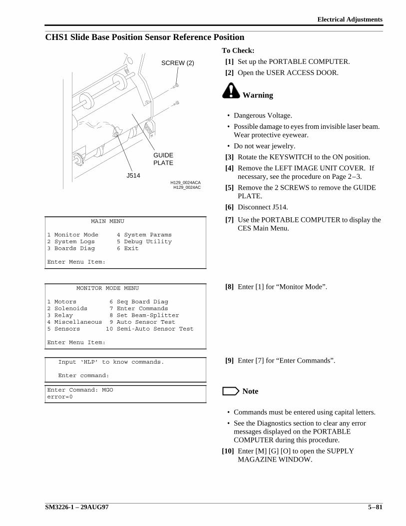
Electrical Adjustments
SM3226-1 – 29AUG97 5–81
CHS1 Slide Base Position Sensor Reference PositionTo Check:
[1] Set up the PORTABLE COMPUTER.
[2] Open the USER ACCESS DOOR.
Warning
• Dangerous Voltage.
• Possible damage to eyes from invisible laser beam.Wear protective eyewear.
• Do not wear jewelry.
[3] Rotate the KEYSWITCH to the ON position.
[4] Remove the LEFT IMAGE UNIT COVER. Ifnecessary, see the procedure on Page 2–3.
[5] Remove the 2 SCREWS to remove the GUIDEPLATE.
[6] Disconnect J514.
[7] Use the PORTABLE COMPUTER to display theCES Main Menu.
[8] Enter [1] for “Monitor Mode”.
[9] Enter [7] for “Enter Commands”.
Note
• Commands must be entered using capital letters.
• See the Diagnostics section to clear any errormessages displayed on the PORTABLECOMPUTER during this procedure.
[10] Enter [M] [G] [O] to open the SUPPLYMAGAZINE WINDOW.
MAIN MENU
1 Monitor Mode 4 System Params2 System Logs 5 Debug Utility3 Boards Diag 6 Exit
Enter Menu Item:
MONITOR MODE MENU
1 Motors 6 Seq Board Diag2 Solenoids 7 Enter Commands3 Relay 8 Set Beam-Splitter4 Miscellaneous 9 Auto Sensor Test5 Sensors 10 Semi-Auto Sensor Test
Enter Menu Item:
Input ‘HLP’ to know commands.
Enter command:
Enter Command: MGOerror=0
H129_0024ACH129_0024ACA
J514
PLATEGUIDE
SCREW (2)
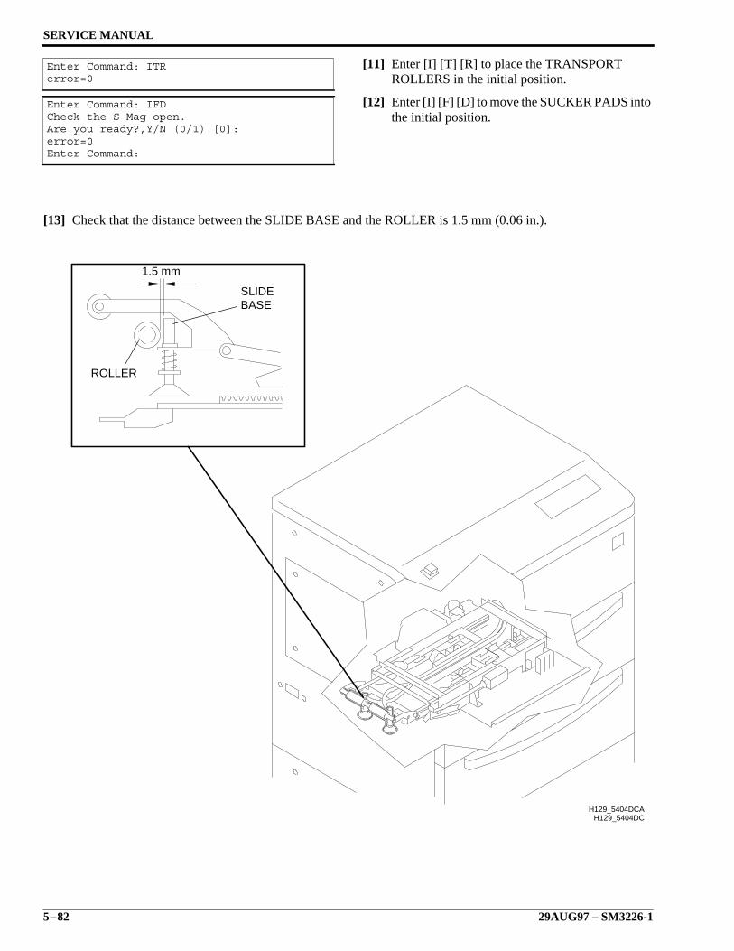
SERVICE MANUAL
5–82 29AUG97 – SM3226-1
[11] Enter [I] [T] [R] to place the TRANSPORTROLLERS in the initial position.
[12] Enter [I] [F] [D] to move the SUCKER PADS intothe initial position.
[13] Check that the distance between the SLIDE BASE and the ROLLER is 1.5 mm (0.06 in.).
Enter Command: ITRerror=0
Enter Command: IFDCheck the S-Mag open.Are you ready?,Y/N (0/1) [0]:error=0Enter Command:
H129_5404DCH129_5404DCA
1.5 mm
BASESLIDE
ROLLER
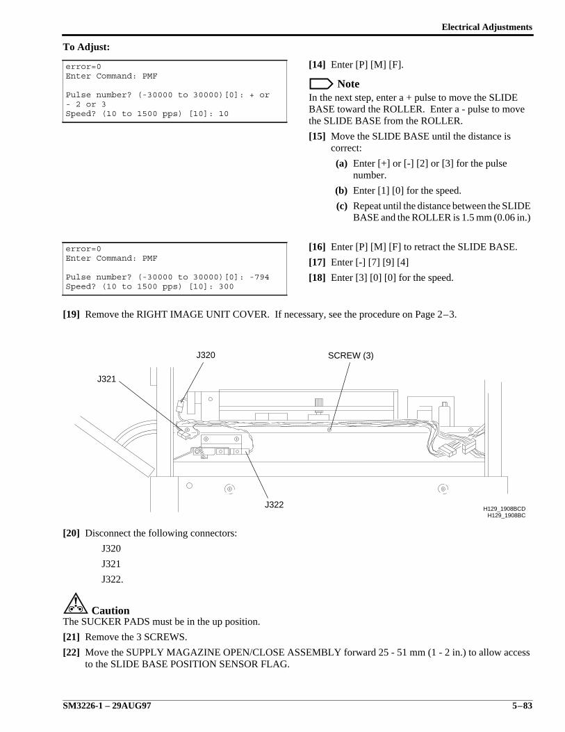
Electrical Adjustments
SM3226-1 – 29AUG97 5–83
To Adjust:
[14] Enter [P] [M] [F].
NoteIn the next step, enter a + pulse to move the SLIDEBASE toward the ROLLER. Enter a - pulse to movethe SLIDE BASE from the ROLLER.
[15] Move the SLIDE BASE until the distance iscorrect:
(a) Enter [+] or [-] [2] or [3] for the pulsenumber.
(b) Enter [1] [0] for the speed.
(c) Repeat until the distance between the SLIDEBASE and the ROLLER is 1.5 mm (0.06 in.)
[16] Enter [P] [M] [F] to retract the SLIDE BASE.
[17] Enter [-] [7] [9] [4]
[18] Enter [3] [0] [0] for the speed.
[19] Remove the RIGHT IMAGE UNIT COVER. If necessary, see the procedure on Page 2–3.
[20] Disconnect the following connectors:
J320
J321
J322.
CautionThe SUCKER PADS must be in the up position.
[21] Remove the 3 SCREWS.
[22] Move the SUPPLY MAGAZINE OPEN/CLOSE ASSEMBLY forward 25 - 51 mm (1 - 2 in.) to allow accessto the SLIDE BASE POSITION SENSOR FLAG.
error=0Enter Command: PMF
Pulse number? (-30000 to 30000)[0]: + or- 2 or 3Speed? (10 to 1500 pps) [10]: 10
error=0Enter Command: PMF
Pulse number? (-30000 to 30000)[0]: -794Speed? (10 to 1500 pps) [10]: 300
H129_1908BCH129_1908BCD
SCREW (3)
J322
J320
J321
SERVICE MANUAL
5–84 29AUG97 – SM3226-1
[23] Enter [P] [H] [T] to observe sensors.
NoteThe state of CHS-1 displayed on the PORTABLECOMPUTER should change between 0 and 1 duringthe next step.
ImportantDo not loosen FLAG SCREWS for the next step.
[24] Observe the state of CHS-1 displayed on thePORTABLE COMPUTER while trying to movethe sensor flag without loosening the mountingscrews.
ImportantIf the state of CHS-1 changes from 0 to 1, theadjustment is complete. Go to Step 33. If the state ofCHS-1 does not change, do the following step.
[25] Enter [P] [M] [F].
[26] Enter [-] [1] [0] for the pulse number.
[27] Enter [1] [0] for the speed.
[28] Enter [P] [H] [T] to observe sensors.
Enter Command: PHTerror=0
error=0Enter Command: PMF
Pulse number? (-30000 to 30000)[0]: -10Speed? (10 to 1500 pps) [10]: 10
Enter Command: PHTerror=0
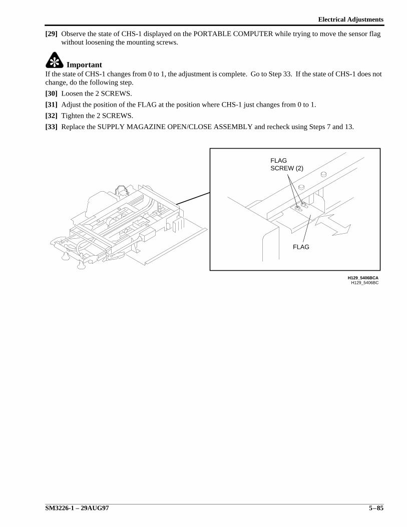
Electrical Adjustments
SM3226-1 – 29AUG97 5–85
[29] Observe the state of CHS-1 displayed on the PORTABLE COMPUTER while trying to move the sensor flagwithout loosening the mounting screws.
ImportantIf the state of CHS-1 changes from 0 to 1, the adjustment is complete. Go to Step 33. If the state of CHS-1 does notchange, do the following step.
[30] Loosen the 2 SCREWS.
[31] Adjust the position of the FLAG at the position where CHS-1 just changes from 0 to 1.
[32] Tighten the 2 SCREWS.
[33] Replace the SUPPLY MAGAZINE OPEN/CLOSE ASSEMBLY and recheck using Steps 7 and 13.
H129_5406BCH129_5406BCA
SCREW (2)FLAG
FLAG
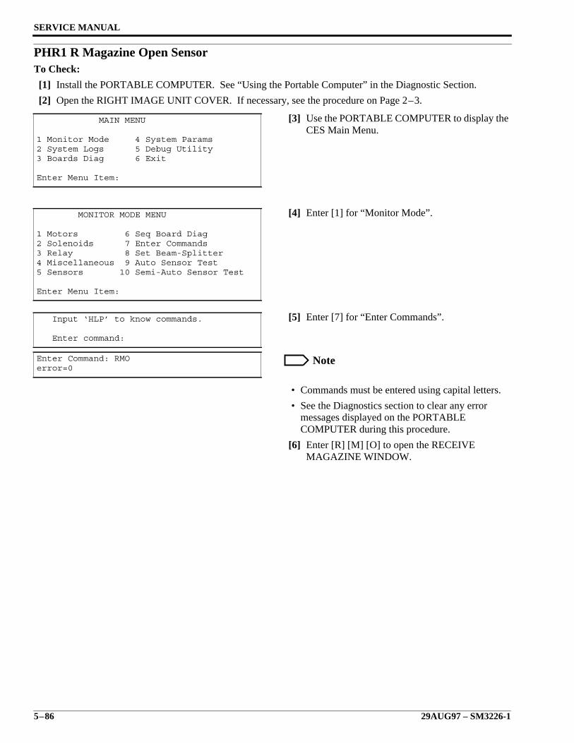
SERVICE MANUAL
5–86 29AUG97 – SM3226-1
PHR1 R Magazine Open SensorTo Check:
[1] Install the PORTABLE COMPUTER. See “Using the Portable Computer” in the Diagnostic Section.
[2] Open the RIGHT IMAGE UNIT COVER. If necessary, see the procedure on Page 2–3.
[3] Use the PORTABLE COMPUTER to display theCES Main Menu.
[4] Enter [1] for “Monitor Mode”.
[5] Enter [7] for “Enter Commands”.
Note
• Commands must be entered using capital letters.
• See the Diagnostics section to clear any errormessages displayed on the PORTABLECOMPUTER during this procedure.
[6] Enter [R] [M] [O] to open the RECEIVEMAGAZINE WINDOW.
MAIN MENU
1 Monitor Mode 4 System Params2 System Logs 5 Debug Utility3 Boards Diag 6 Exit
Enter Menu Item:
MONITOR MODE MENU
1 Motors 6 Seq Board Diag2 Solenoids 7 Enter Commands3 Relay 8 Set Beam-Splitter4 Miscellaneous 9 Auto Sensor Test5 Sensors 10 Semi-Auto Sensor Test
Enter Menu Item:
Input ‘HLP’ to know commands.
Enter command:
Enter Command: RMOerror=0
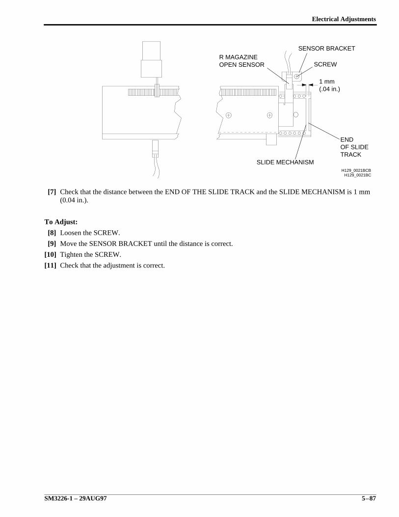
Electrical Adjustments
SM3226-1 – 29AUG97 5–87
[7] Check that the distance between the END OF THE SLIDE TRACK and the SLIDE MECHANISM is 1 mm(0.04 in.).
To Adjust:
[8] Loosen the SCREW.
[9] Move the SENSOR BRACKET until the distance is correct.
[10] Tighten the SCREW.
[11] Check that the adjustment is correct.
H129_0021BC
TRACKOF SLIDE END
H129_0021BCB
(.04 in.)1 mm
SCREW
SENSOR BRACKET
SLIDE MECHANISM
OPEN SENSORR MAGAZINE
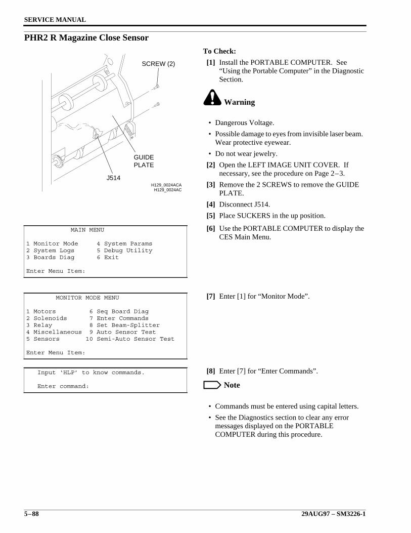
SERVICE MANUAL
5–88 29AUG97 – SM3226-1
PHR2 R Magazine Close SensorTo Check:
[1] Install the PORTABLE COMPUTER. See“Using the Portable Computer” in the DiagnosticSection.
Warning
• Dangerous Voltage.
• Possible damage to eyes from invisible laser beam.Wear protective eyewear.
• Do not wear jewelry.
[2] Open the LEFT IMAGE UNIT COVER. Ifnecessary, see the procedure on Page 2–3.
[3] Remove the 2 SCREWS to remove the GUIDEPLATE.
[4] Disconnect J514.
[5] Place SUCKERS in the up position.
[6] Use the PORTABLE COMPUTER to display theCES Main Menu.
[7] Enter [1] for “Monitor Mode”.
[8] Enter [7] for “Enter Commands”.
Note
• Commands must be entered using capital letters.
• See the Diagnostics section to clear any errormessages displayed on the PORTABLECOMPUTER during this procedure.
MAIN MENU
1 Monitor Mode 4 System Params2 System Logs 5 Debug Utility3 Boards Diag 6 Exit
Enter Menu Item:
MONITOR MODE MENU
1 Motors 6 Seq Board Diag2 Solenoids 7 Enter Commands3 Relay 8 Set Beam-Splitter4 Miscellaneous 9 Auto Sensor Test5 Sensors 10 Semi-Auto Sensor Test
Enter Menu Item:
Input ‘HLP’ to know commands.
Enter command:
H129_0024ACH129_0024ACA
J514
PLATEGUIDE
SCREW (2)
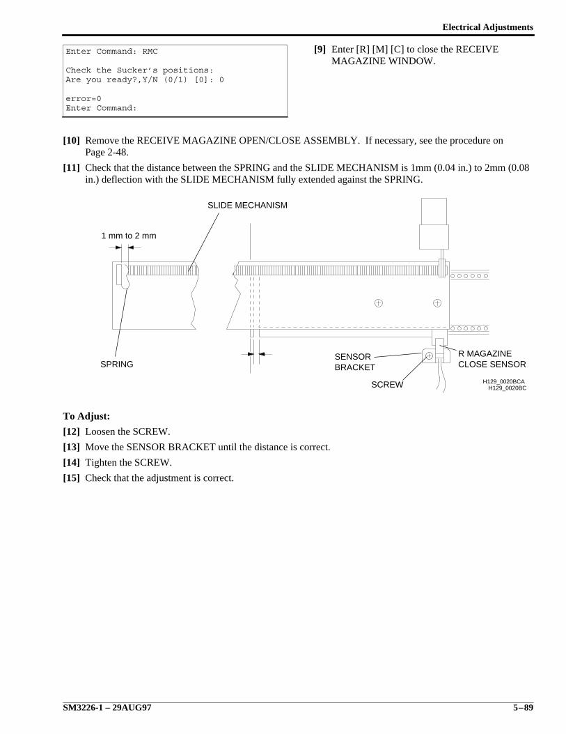
Electrical Adjustments
SM3226-1 – 29AUG97 5–89
[9] Enter [R] [M] [C] to close the RECEIVEMAGAZINE WINDOW.
[10] Remove the RECEIVE MAGAZINE OPEN/CLOSE ASSEMBLY. If necessary, see the procedure onPage 2-48.
[11] Check that the distance between the SPRING and the SLIDE MECHANISM is 1mm (0.04 in.) to 2mm (0.08in.) deflection with the SLIDE MECHANISM fully extended against the SPRING.
To Adjust:
[12] Loosen the SCREW.
[13] Move the SENSOR BRACKET until the distance is correct.
[14] Tighten the SCREW.
[15] Check that the adjustment is correct.
Enter Command: RMC
Check the Sucker’s positions:Are you ready?,Y/N (0/1) [0]: 0
error=0Enter Command:
H129_0020BCH129_0020BCA
R MAGAZINECLOSE SENSOR
SCREW
SENSORBRACKETSPRING
1 mm to 2 mm
SLIDE MECHANISM
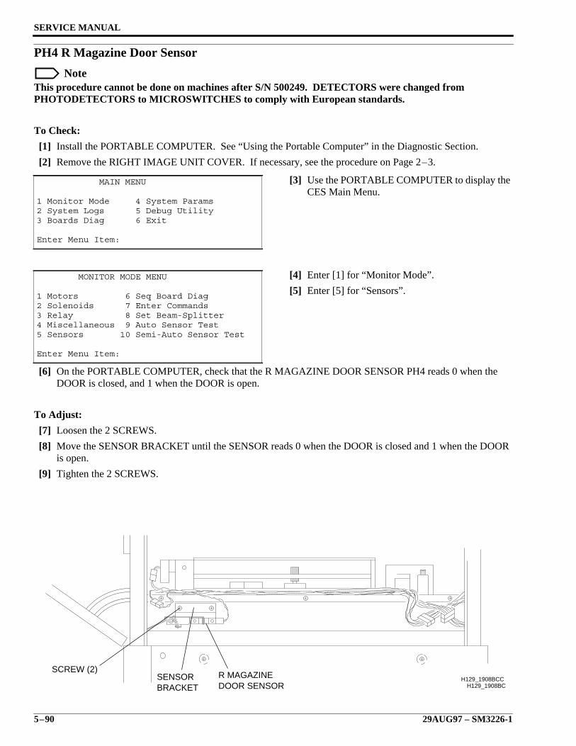
SERVICE MANUAL
5–90 29AUG97 – SM3226-1
PH4 R Magazine Door Sensor
NoteThis procedure cannot be done on machines after S/N 500249. DETECTORS were changed fromPHOTODETECTORS to MICROSWITCHES to comply with European standards.
To Check:
[1] Install the PORTABLE COMPUTER. See “Using the Portable Computer” in the Diagnostic Section.
[2] Remove the RIGHT IMAGE UNIT COVER. If necessary, see the procedure on Page 2–3.
[3] Use the PORTABLE COMPUTER to display theCES Main Menu.
[4] Enter [1] for “Monitor Mode”.
[5] Enter [5] for “Sensors”.
[6] On the PORTABLE COMPUTER, check that the R MAGAZINE DOOR SENSOR PH4 reads 0 when theDOOR is closed, and 1 when the DOOR is open.
To Adjust:
[7] Loosen the 2 SCREWS.
[8] Move the SENSOR BRACKET until the SENSOR reads 0 when the DOOR is closed and 1 when the DOORis open.
[9] Tighten the 2 SCREWS.
MAIN MENU
1 Monitor Mode 4 System Params2 System Logs 5 Debug Utility3 Boards Diag 6 Exit
Enter Menu Item:
MONITOR MODE MENU
1 Motors 6 Seq Board Diag2 Solenoids 7 Enter Commands3 Relay 8 Set Beam-Splitter4 Miscellaneous 9 Auto Sensor Test5 Sensors 10 Semi-Auto Sensor Test
Enter Menu Item:
H129_1908BCH129_1908BCC
SCREW (2)SENSORBRACKET
R MAGAZINEDOOR SENSOR
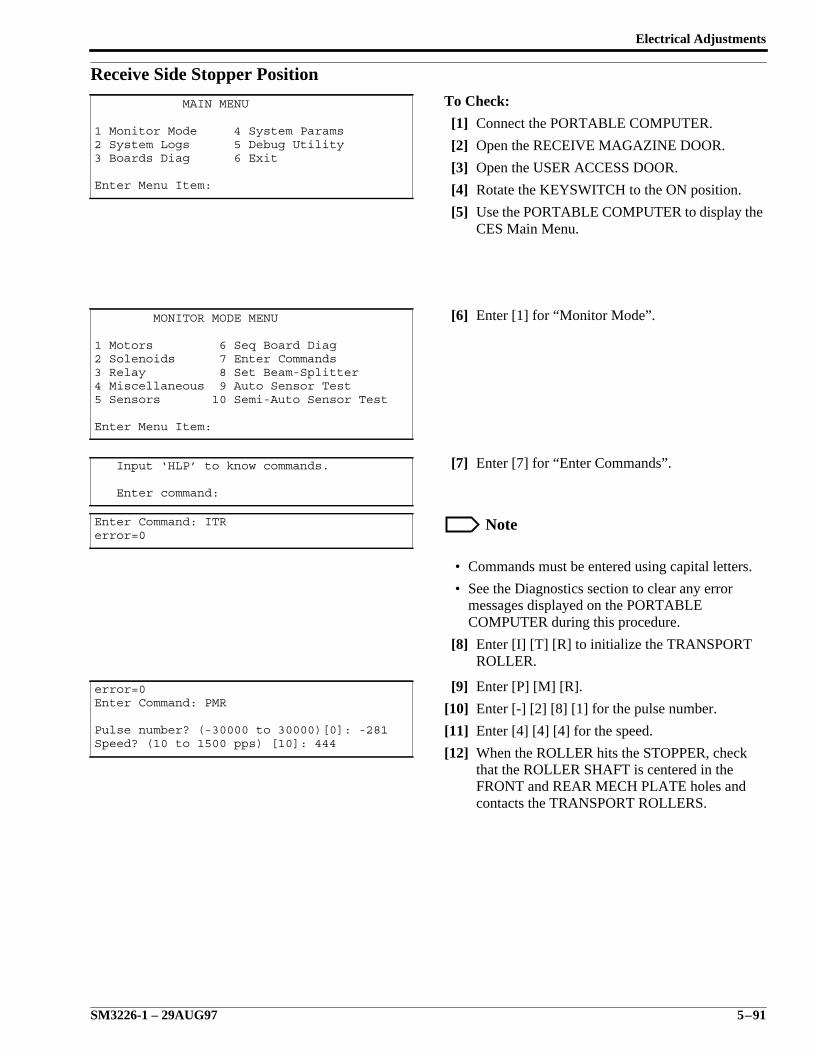
Electrical Adjustments
SM3226-1 – 29AUG97 5–91
Receive Side Stopper PositionTo Check:
[1] Connect the PORTABLE COMPUTER.
[2] Open the RECEIVE MAGAZINE DOOR.
[3] Open the USER ACCESS DOOR.
[4] Rotate the KEYSWITCH to the ON position.
[5] Use the PORTABLE COMPUTER to display theCES Main Menu.
[6] Enter [1] for “Monitor Mode”.
[7] Enter [7] for “Enter Commands”.
Note
• Commands must be entered using capital letters.
• See the Diagnostics section to clear any errormessages displayed on the PORTABLECOMPUTER during this procedure.
[8] Enter [I] [T] [R] to initialize the TRANSPORTROLLER.
[9] Enter [P] [M] [R].
[10] Enter [-] [2] [8] [1] for the pulse number.
[11] Enter [4] [4] [4] for the speed.
[12] When the ROLLER hits the STOPPER, checkthat the ROLLER SHAFT is centered in theFRONT and REAR MECH PLATE holes andcontacts the TRANSPORT ROLLERS.
MAIN MENU
1 Monitor Mode 4 System Params2 System Logs 5 Debug Utility3 Boards Diag 6 Exit
Enter Menu Item:
MONITOR MODE MENU
1 Motors 6 Seq Board Diag2 Solenoids 7 Enter Commands3 Relay 8 Set Beam-Splitter4 Miscellaneous 9 Auto Sensor Test5 Sensors 10 Semi-Auto Sensor Test
Enter Menu Item:
Input ‘HLP’ to know commands.
Enter command:
Enter Command: ITRerror=0
error=0Enter Command: PMR
Pulse number? (-30000 to 30000)[0]: -281Speed? (10 to 1500 pps) [10]: 444
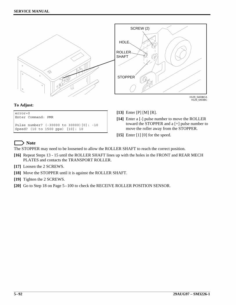
SERVICE MANUAL
5–92 29AUG97 – SM3226-1
To Adjust:
[13] Enter [P] [M] [R].
[14] Enter a [-] pulse number to move the ROLLERtoward the STOPPER and a [+] pulse number tomove the roller away from the STOPPER.
[15] Enter [1] [0] for the speed.
NoteThe STOPPER may need to be loosened to allow the ROLLER SHAFT to reach the correct position.
[16] Repeat Steps 13 - 15 until the ROLLER SHAFT lines up with the holes in the FRONT and REAR MECHPLATES and contacts the TRANSPORT ROLLER.
[17] Loosen the 2 SCREWS.
[18] Move the STOPPER until it is against the ROLLER SHAFT.
[19] Tighten the 2 SCREWS.
[20] Go to Step 18 on Page 5–100 to check the RECEIVE ROLLER POSITION SENSOR.
error=0Enter Command: PMR
Pulse number? (-30000 to 30000)[0]: -10Speed? (10 to 1500 pps) [10]: 10
H129_5403BC
HOLE
SHAFTROLLER
STOPPER
SCREW (2)
H129_5403BCA
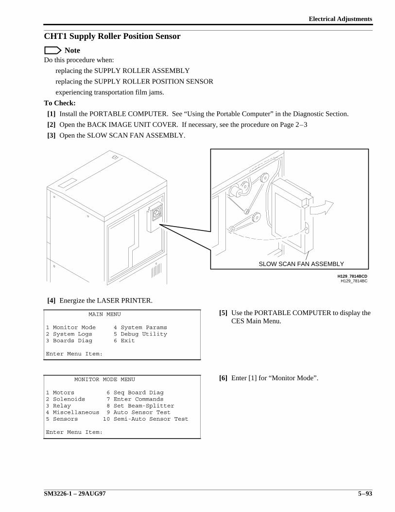
Electrical Adjustments
SM3226-1 – 29AUG97 5–93
CHT1 Supply Roller Position Sensor
NoteDo this procedure when:
replacing the SUPPLY ROLLER ASSEMBLY
replacing the SUPPLY ROLLER POSITION SENSOR
experiencing transportation film jams.
To Check:
[1] Install the PORTABLE COMPUTER. See “Using the Portable Computer” in the Diagnostic Section.
[2] Open the BACK IMAGE UNIT COVER. If necessary, see the procedure on Page 2–3
[3] Open the SLOW SCAN FAN ASSEMBLY.
[4] Energize the LASER PRINTER.
[5] Use the PORTABLE COMPUTER to display theCES Main Menu.
[6] Enter [1] for “Monitor Mode”.
MAIN MENU
1 Monitor Mode 4 System Params2 System Logs 5 Debug Utility3 Boards Diag 6 Exit
Enter Menu Item:
MONITOR MODE MENU
1 Motors 6 Seq Board Diag2 Solenoids 7 Enter Commands3 Relay 8 Set Beam-Splitter4 Miscellaneous 9 Auto Sensor Test5 Sensors 10 Semi-Auto Sensor Test
Enter Menu Item:
H129_7814BCH129_7814BCD
SLOW SCAN FAN ASSEMBLY
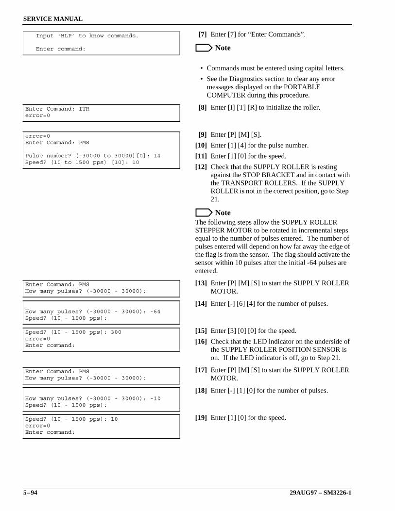
SERVICE MANUAL
5–94 29AUG97 – SM3226-1
[7] Enter [7] for “Enter Commands”.
Note
• Commands must be entered using capital letters.
• See the Diagnostics section to clear any errormessages displayed on the PORTABLECOMPUTER during this procedure.
[8] Enter [I] [T] [R] to initialize the roller.
[9] Enter [P] [M] [S].
[10] Enter [1] [4] for the pulse number.
[11] Enter [1] [0] for the speed.
[12] Check that the SUPPLY ROLLER is restingagainst the STOP BRACKET and in contact withthe TRANSPORT ROLLERS. If the SUPPLYROLLER is not in the correct position, go to Step21.
NoteThe following steps allow the SUPPLY ROLLERSTEPPER MOTOR to be rotated in incremental stepsequal to the number of pulses entered. The number ofpulses entered will depend on how far away the edge ofthe flag is from the sensor. The flag should activate thesensor within 10 pulses after the initial -64 pulses areentered.
[13] Enter [P] [M] [S] to start the SUPPLY ROLLERMOTOR.
[14] Enter [-] [6] [4] for the number of pulses.
[15] Enter [3] [0] [0] for the speed.
[16] Check that the LED indicator on the underside ofthe SUPPLY ROLLER POSITION SENSOR ison. If the LED indicator is off, go to Step 21.
[17] Enter [P] [M] [S] to start the SUPPLY ROLLERMOTOR.
[18] Enter [-] [1] [0] for the number of pulses.
[19] Enter [1] [0] for the speed.
Input ‘HLP’ to know commands.
Enter command:
Enter Command: ITRerror=0
error=0Enter Command: PMS
Pulse number? (-30000 to 30000)[0]: 14Speed? (10 to 1500 pps) [10]: 10
Enter Command: PMSHow many pulses? (-30000 - 30000):
How many pulses? (-30000 - 30000): -64Speed? (10 - 1500 pps):
Speed? (10 - 1500 pps): 300error=0Enter command:
Enter Command: PMSHow many pulses? (-30000 - 30000):
How many pulses? (-30000 - 30000): -10Speed? (10 - 1500 pps):
Speed? (10 - 1500 pps): 10error=0Enter command:
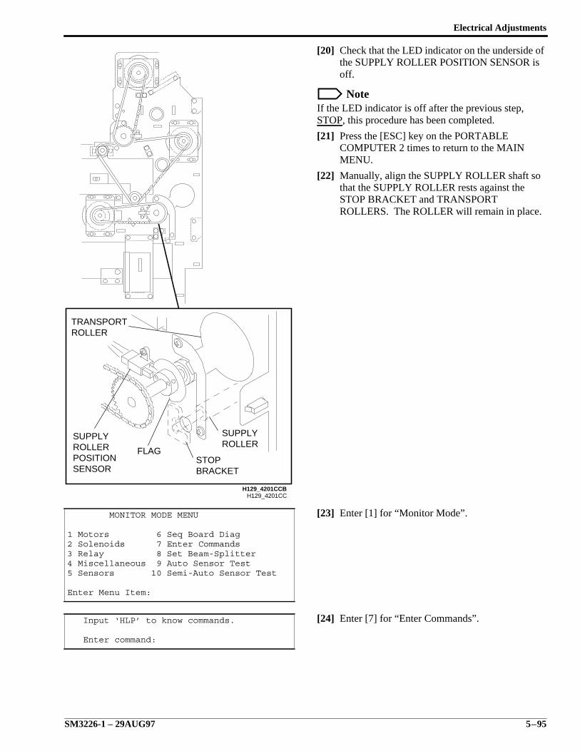
Electrical Adjustments
SM3226-1 – 29AUG97 5–95
[20] Check that the LED indicator on the underside ofthe SUPPLY ROLLER POSITION SENSOR isoff.
NoteIf the LED indicator is off after the previous step,STOP, this procedure has been completed.
[21] Press the [ESC] key on the PORTABLECOMPUTER 2 times to return to the MAINMENU.
[22] Manually, align the SUPPLY ROLLER shaft sothat the SUPPLY ROLLER rests against theSTOP BRACKET and TRANSPORTROLLERS. The ROLLER will remain in place.
[23] Enter [1] for “Monitor Mode”.
[24] Enter [7] for “Enter Commands”.
MONITOR MODE MENU
1 Motors 6 Seq Board Diag2 Solenoids 7 Enter Commands3 Relay 8 Set Beam-Splitter4 Miscellaneous 9 Auto Sensor Test5 Sensors 10 Semi-Auto Sensor Test
Enter Menu Item:
Input ‘HLP’ to know commands.
Enter command:
H129_4201CC
FLAG
SENSORPOSITIONROLLERSUPPLY
ROLLERTRANSPORT
ROLLERSUPPLY
BRACKETSTOP
H129_4201CCB
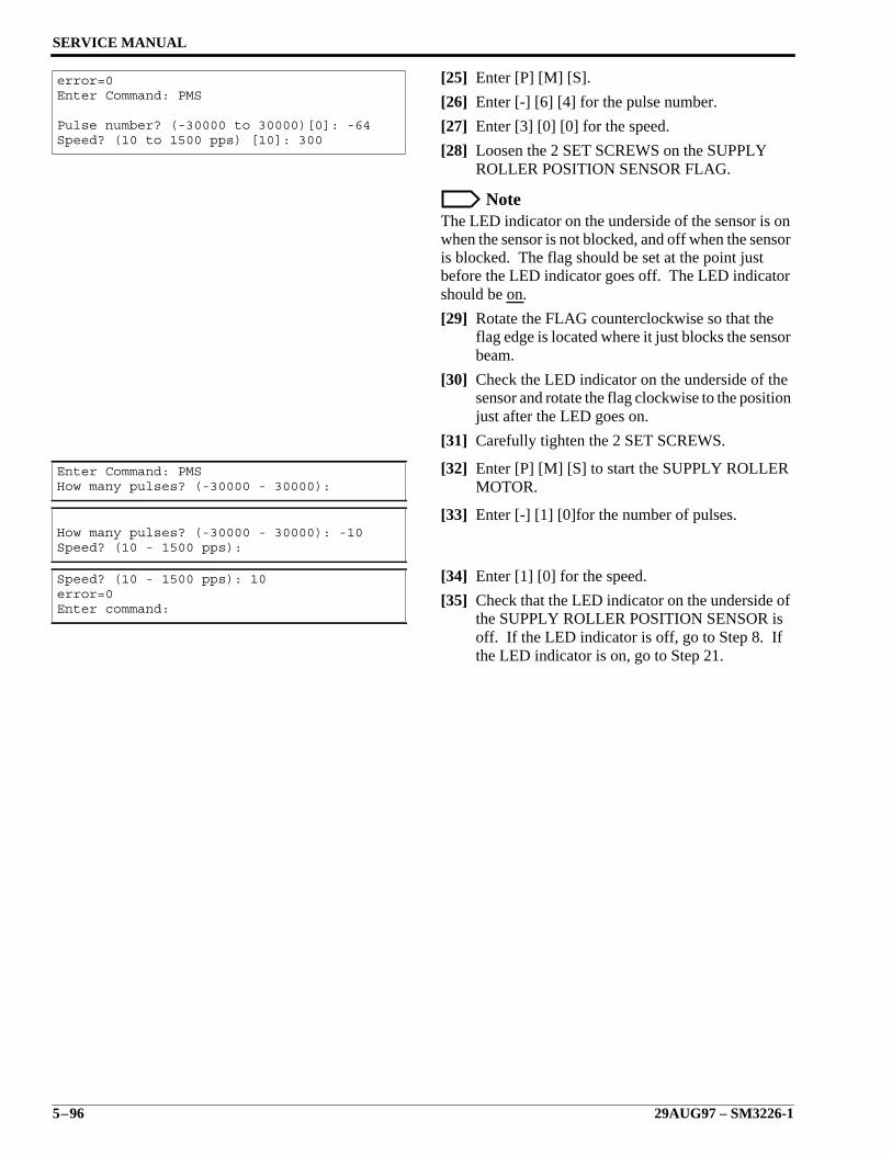
SERVICE MANUAL
5–96 29AUG97 – SM3226-1
[25] Enter [P] [M] [S].
[26] Enter [-] [6] [4] for the pulse number.
[27] Enter [3] [0] [0] for the speed.
[28] Loosen the 2 SET SCREWS on the SUPPLYROLLER POSITION SENSOR FLAG.
NoteThe LED indicator on the underside of the sensor is onwhen the sensor is not blocked, and off when the sensoris blocked. The flag should be set at the point justbefore the LED indicator goes off. The LED indicatorshould be on.
[29] Rotate the FLAG counterclockwise so that theflag edge is located where it just blocks the sensorbeam.
[30] Check the LED indicator on the underside of thesensor and rotate the flag clockwise to the positionjust after the LED goes on.
[31] Carefully tighten the 2 SET SCREWS.
[32] Enter [P] [M] [S] to start the SUPPLY ROLLERMOTOR.
[33] Enter [-] [1] [0]for the number of pulses.
[34] Enter [1] [0] for the speed.
[35] Check that the LED indicator on the underside ofthe SUPPLY ROLLER POSITION SENSOR isoff. If the LED indicator is off, go to Step 8. Ifthe LED indicator is on, go to Step 21.
error=0Enter Command: PMS
Pulse number? (-30000 to 30000)[0]: -64Speed? (10 to 1500 pps) [10]: 300
Enter Command: PMSHow many pulses? (-30000 - 30000):
How many pulses? (-30000 - 30000): -10Speed? (10 - 1500 pps):
Speed? (10 - 1500 pps): 10error=0Enter command:
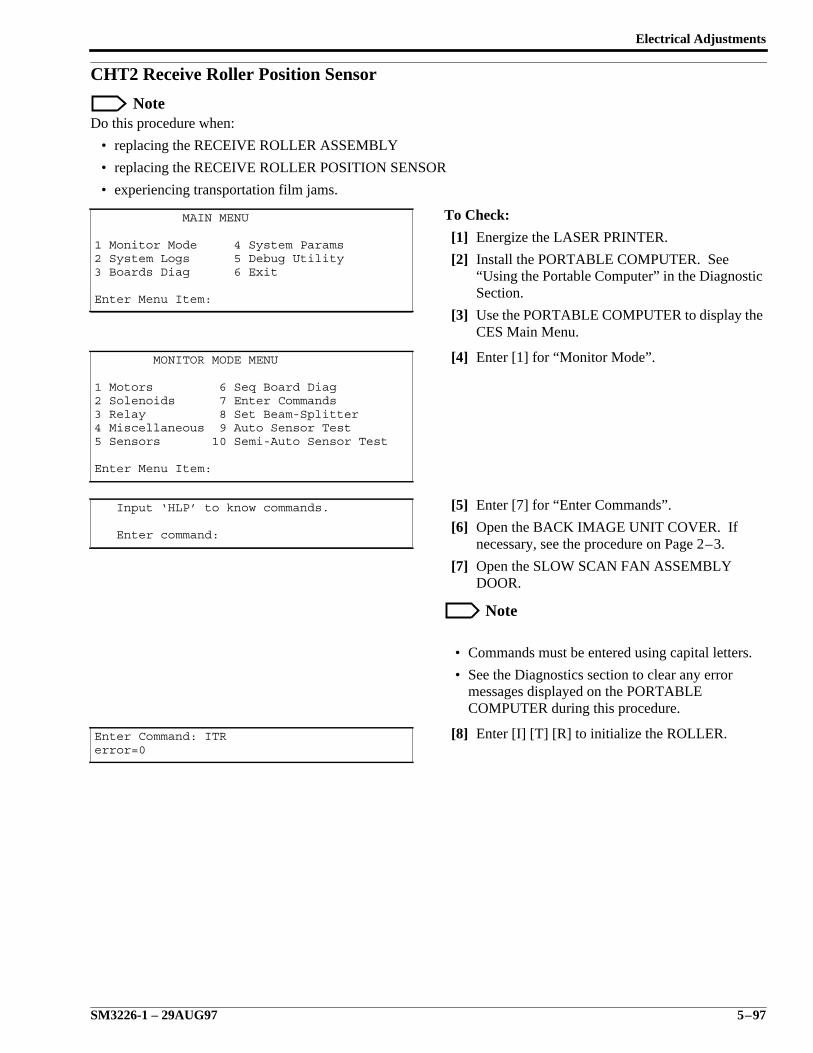
Electrical Adjustments
SM3226-1 – 29AUG97 5–97
CHT2 Receive Roller Position Sensor
NoteDo this procedure when:
• replacing the RECEIVE ROLLER ASSEMBLY
• replacing the RECEIVE ROLLER POSITION SENSOR
• experiencing transportation film jams.
To Check:
[1] Energize the LASER PRINTER.
[2] Install the PORTABLE COMPUTER. See“Using the Portable Computer” in the DiagnosticSection.
[3] Use the PORTABLE COMPUTER to display theCES Main Menu.
[4] Enter [1] for “Monitor Mode”.
[5] Enter [7] for “Enter Commands”.
[6] Open the BACK IMAGE UNIT COVER. Ifnecessary, see the procedure on Page 2–3.
[7] Open the SLOW SCAN FAN ASSEMBLYDOOR.
Note
• Commands must be entered using capital letters.
• See the Diagnostics section to clear any errormessages displayed on the PORTABLECOMPUTER during this procedure.
[8] Enter [I] [T] [R] to initialize the ROLLER.
MAIN MENU
1 Monitor Mode 4 System Params2 System Logs 5 Debug Utility3 Boards Diag 6 Exit
Enter Menu Item:
MONITOR MODE MENU
1 Motors 6 Seq Board Diag2 Solenoids 7 Enter Commands3 Relay 8 Set Beam-Splitter4 Miscellaneous 9 Auto Sensor Test5 Sensors 10 Semi-Auto Sensor Test
Enter Menu Item:
Input ‘HLP’ to know commands.
Enter command:
Enter Command: ITRerror=0
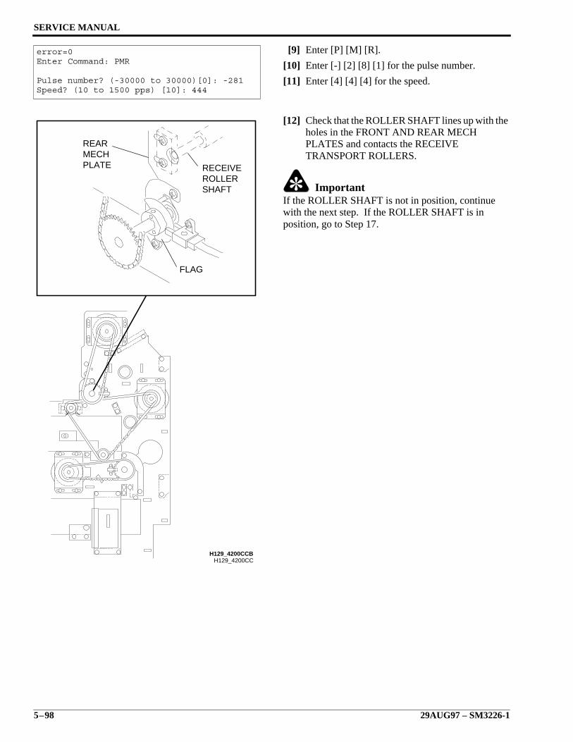
SERVICE MANUAL
5–98 29AUG97 – SM3226-1
[9] Enter [P] [M] [R].
[10] Enter [-] [2] [8] [1] for the pulse number.
[11] Enter [4] [4] [4] for the speed.
[12] Check that the ROLLER SHAFT lines up with theholes in the FRONT AND REAR MECHPLATES and contacts the RECEIVETRANSPORT ROLLERS.
ImportantIf the ROLLER SHAFT is not in position, continuewith the next step. If the ROLLER SHAFT is inposition, go to Step 17.
error=0Enter Command: PMR
Pulse number? (-30000 to 30000)[0]: -281Speed? (10 to 1500 pps) [10]: 444
H129_4200CC
FLAG
PLATEMECHREAR
SHAFTROLLERRECEIVE
H129_4200CCB

Electrical Adjustments
SM3226-1 – 29AUG97 5–99
[13] Enter [P] [M] [R].
NoteThe number of pulses entered depends on the distancethe ROLLER SHAFT must be moved.
[14] Enter a negative pulse number to move theROLLER toward the STOPPER and a positivepulse number to move the roller away from theSTOPPER.
[15] Enter [1] [0] for the speed.
[16] Repeat Steps 13 - 15 until the ROLLER SHAFTlines up with the holes in the FRONT and REARMECH PLATES and contacts the TRANSPORTROLLER.
error=0Enter Command: PMR
Pulse number? (-30000 to 30000)[0]: -10Speed? (10 to 1500 pps) [10]: 10
SERVICE MANUAL
5–100 29AUG97 – SM3226-1
[17] Check that the RECEIVE ROLLER is restingagainst the STOP BRACKET.
ImportantIf the RECEIVE ROLLER is in position continue withthe next step. If the RECEIVE ROLLER is not inposition do the Receive Side Stopper Adjustmentprocedure beginning at Step 13 on Page 5–92.
[18] Enter [P] [M] [R] to start the ROLLER MOTOR.
[19] Enter [5] [6] [2] for the pulse number.
[20] Enter [4] [4] [4] for the speed.
[21] Check that the LED INDICATOR on theSENSOR is off.
ImportantIf the LED INDICATOR is on, go to Step 26.
[22] Enter [P] [M] [R] to start the ROLLER MOTOR.
[23] Enter [5] for the pulse number.
[24] Enter [1] [0] for the speed.
[25] Check to see that the LED INDICATOR on theSENSOR is on. If it is on, STOP, this adjustmentis completed. If it is off, go to Step 30.
[26] Loosen the 2 SETSCREWS.
[27] Rotate the FLAG counterclockwise until the LEDINDICATOR on the SENSOR just turns off.
[28] Carefully tighten the 2 SETSCREWS.
[29] Go to Step 8 to repeat the check procedure.
[30] Loosen the 2 SETSCREWS.
[31] Rotate the FLAG clockwise until the LEDINDICATOR on the SENSOR just turns on.
[32] Carefully tighten the 2 SETSCREWS.
[33] Go to Step 8 to repeat the check procedure.
error=0Enter Command: PMR
Pulse number? (-30000 to 30000)[0]: 562Speed? (10 to 1500 pps) [10]: 444
error=0Enter Command: PMR
Pulse number? (-30000 to 30000)[0]: 5Speed? (10 to 1500 pps) [10]: 10
Preventive Maintenance Checklist
SM3226-1 – 29AUG97 6–1
Section 6: Preventive Maintenance Checklist
CautionDo not touch the POLYGON MIRROR surface.
Read the Error History and Error Frequency Logs. Look for trends and possibleproblems. Clear both logs.
Print test patterns. Compare to test patterns made at installation. Check forartifacts.
If artifacts show on the film, clean the OUTPUT MIRROR and LENSES withSpectro•Grade Acetone, Part No. 1C8068 and LENS PAPER TL-2278.
If necessary, calibrate the LASER PRINTER using the procedure on Page 4–2.
Use a soft cloth to clean the surfaces of the 2 film SUCKERS.
Use alcohol to clean the following rollers:UPPER TRANSPORT ROLLER
LOWER TRANSPORT ROLLER
RECEIVE ROLLER
SUPPLY ROLLER
PINCH ROLLER.
Clean or replace the following filters:IMAGING UNIT INTAKE FAN FILTER, located under the SUPPLYMAGAZINE.
CARD RACK INTAKE FILTER
FRONT COVER FILTER
Clean the SLOW SCAN MOTOR FAN COVER.

sm3226_1.6.doc
Printed In USA
HEALTH IMAGING
EASTMAN KODAK COMPANY ROCHESTER, N.Y. 14650
Preventive Maintenance Checklist
Publication History:
Print Date Pub. No. ECO No. Affected Pages File Name Notes
Feb97 SM3226-1 N/A Pages 4-16 through4-21.
sm3226_1_10feb97.book Caps conversion toFrame
29Aug97 SM3226-1 N/A Page references inSection 5.
sm3226_1_29aug97.book
Kodak and Ektascan are trademarks.