Embed Size (px)
Citation preview
®
HP Omnibook 6000/6100
Service Manual

ii HP Omnibook 6000/6100
Notice
In a continuing effort to improve the quality of our products, technical and environmental informationin this document is subject to change without notice.
This manual and any examples contained herein are provided “as is” and are subject to change withoutnotice. Hewlett-Packard Company makes no warranty of any kind with regard to this manual,including, but not limited to, the implied warranties of merchantability and fitness for a particularpurpose. Hewlett-Packard Co. shall not be liable for any errors or for incidental or consequentialdamages in connection with the furnishing, performance, or use of this manual or the examples herein.
Consumer transactions in Australia and the United Kingdom: The above disclaimers and limitationsshall not apply to Consumer transactions in Australia and the United Kingdom and shall not affect thestatutory rights of Consumers.
© Copyright Hewlett-Packard Company 1998–2001. All rights reserved. Reproduction, adaptation, ortranslation of this manual is prohibited without prior written permission of Hewlett-Packard Company,except as allowed under the copyright laws.
The programs that control this product are copyrighted and all rights are reserved. Reproduction,adaptation, or translation of those programs without prior written permission of Hewlett-Packard Co.is also prohibited.
Portions of the programs that control this product may also be copyrighted by Microsoft Corporation,SystemSoft Corp., Phoenix Technologies, Ltd., ATI Technologies Inc., and Adobe SystemsIncorporated. See the individual programs for additional copyright notices.
This product incorporates copyright protection technology that is protected by method claims ofcertain U.S. patents and other intellectual property rights owned by Macrovision Corporation andother rights owners. Use of this copyright protection technology must be authorized by MacrovisionCorporation and is intended for home and other limited viewing uses only unless otherwise authorizedby Macrovision Corporation. Reverse engineering or disassembly is prohibited.
Microsoft®, MS-DOS®, and Windows® are U.S. registered trademarks of Microsoft Corporation.Pentium® and the Intel Inside logo are U.S. registered trademarks and Celeron™ and SpeedStep™are U.S. trademarks of Intel Corporation. TrackPoint™ is a U.S. trademark of International BusinessMachines. Adobe® and Acrobat® are trademarks of Adobe Systems Incorporated.
All certifications may not be completed at product introduction. Check with your HP reseller forcertification status.
This equipment is subject to FCC rules. It will comply with the appropriate FCC rules before finaldelivery to the buyer.
Hewlett-Packard CompanyMobile Computing Division19310 Pruneridge Ave.Cupertino, CA 95014, U.S.A.
Edition History
Edition 2 ............................. June 2001
HP Omnibook 6000/6100 iii
ContentsProduct Information ......................................................................................................1-1
Features......................................................................................................................................... 1-3Operation ...................................................................................................................................... 1-5
Turning the Computer On and Off ........................................................................................ 1-5Checking the Status of the Computer .................................................................................... 1-6Using Fn Hot Keys................................................................................................................. 1-7Resetting the Computer.......................................................................................................... 1-8
Specifications................................................................................................................................ 1-9Internal Design............................................................................................................................ 1-14
Removal and Replacement ............................................................................................2-1Disassembly Flowchart................................................................................................................. 2-2Removing the Battery (User-Replaceable) ................................................................................... 2-4Removing a Plug-In Module (User-Replaceable)......................................................................... 2-5Removing an SDRAM Module (User-Replaceable) ................................................................... 2-6Removing the Hard Disk Drive (User-Replaceable) .................................................................... 2-7Removing Mini-PCI Card #1 (User-Replaceable)...................................................................... 2-10Removing the Power Button Panel (User-Replaceable)............................................................. 2-11Replacing Small Parts (User-Replaceable)................................................................................. 2-12Removing the Display Assembly (HP Authorized Service Providers Only).............................. 2-13Removing the Keyboard (HP Authorized Service Providers Only) ........................................... 2-15Removing the Heatsink (with Fan) (HP Authorized Service Providers Only) ........................... 2-17Removing the CPU Module (HP Authorized Service Providers Only)...................................... 2-19Removing the Top Case (HP Authorized Service Providers Only)............................................ 2-21Removing the Motherboard or Bottom Case (HP Authorized Service Providers Only) ............ 2-24
Replacing the Motherboard ................................................................................................. 2-28Replacing the Bottom Case.................................................................................................. 2-32
Repairing the BIOS IC (HP Authorized Service Providers Only).............................................. 2-33Removing Other Components (HP Authorized Service Providers Only)................................... 2-34
Troubleshooting and Diagnostics..................................................................................3-1Troubleshooting............................................................................................................................ 3-2
Checking for Customer Abuse............................................................................................... 3-3Troubleshooting the Problem................................................................................................. 3-3Verifying the Repair .............................................................................................................. 3-4Suggestions for Troubleshooting ........................................................................................... 3-5
Diagnostic Tools......................................................................................................................... 3-17Overview of Diagnostic Tools ............................................................................................. 3-17Power-On Self-Test ............................................................................................................. 3-24Sycard PCCtest 450 CardBus Card (Optional).................................................................... 3-27Desktop Management Interface (DMI)................................................................................ 3-28BIOS Setup Utility............................................................................................................... 3-29
Replaceable Parts ...........................................................................................................4-1
Reference Information...................................................................................................5-1Password Removal Policy ............................................................................................................ 5-1Hewlett-Packard Display Quality Statement ................................................................................ 5-2Service Notes and Obsolete Parts ................................................................................................. 5-4

iv HP Omnibook 6000/6100
FiguresFigure 1-1. Omnibook — Front View..................................................................................................1-3Figure 1-2. Omnibook — Back View ..................................................................................................1-4Figure 1-3. Omnibook — Bottom View...............................................................................................1-4Figure 1-4. Resetting the Computer .....................................................................................................1-8Figure 1-5. Replaceable Module Diagram .........................................................................................1-14Figure 2-1. Disassembly Flow..............................................................................................................2-3Figure 2-2. Removing the Battery ........................................................................................................2-4Figure 2-3. Removing a Module ..........................................................................................................2-5Figure 2-4. Removing a Module ..........................................................................................................2-5Figure 2-5. Removing a SDRAM Module ...........................................................................................2-6Figure 2-6. Removing the Hard Disk Drive .........................................................................................2-7Figure 2-7. Removing the Hard Disk Case ..........................................................................................2-8Figure 2-8. Removing the Mini-PCI Card..........................................................................................2-10Figure 2-9. Removing the Power Button Panel..................................................................................2-11Figure 2-10. Removing the Display ...................................................................................................2-14Figure 2-11. Removing the Keyboard ................................................................................................2-15Figure 2-12. Unplugging the Keyboard Cables..................................................................................2-16Figure 2-13. Removing the Heatsink..................................................................................................2-17Figure 2-14. Removing the CPU Module...........................................................................................2-19Figure 2-15. Removing the Top Case: Omnibook 6100 Models .......................................................2-22Figure 2-16. Removing the Top Case: Omnibook 6000 Models .......................................................2-23Figure 2-17. Removing the Motherboard: Omnibook 6100 Models..................................................2-25Figure 2-18. Removing the Motherboard: Omnibook 6000 Models..................................................2-26Figure 2-19. Installing Docking Doors...............................................................................................2-27Figure 2-20. Installing the Lower PCMCIA Door .............................................................................2-27Figure 2-21. Replacing Motherboard Components: Omnibook 6100 Models ...................................2-29Figure 2-22. Replacing Motherboard Components: Omnibook 6000 Models ...................................2-30Figure 2-23. Example of Serial Number Label ..................................................................................2-32Figure 2-24. Boot-Block Jumper........................................................................................................2-34Figure 3-1. Basic Troubleshooting Steps .............................................................................................3-2Figure 3-2. Diagnostic Screens — Basic and Advanced....................................................................3-17Figure 3-3. Serial and Parallel Loopback Connectors........................................................................3-19Figure 4-1. Exploded View ..................................................................................................................4-2

HP Omnibook 6000/6100 v
TablesTable 1-1. Omnibook 6000/6100 Models............................................................................................ 1-1Table 1-2. Product Comparisons ......................................................................................................... 1-2Table 1-3. Activating Power Modes.................................................................................................... 1-5Table 1-4. Main Status Lights (front of computer).............................................................................. 1-6Table 1-5. Keyboard Status Lights ...................................................................................................... 1-6Table 1-6. Fn Hot Keys ....................................................................................................................... 1-7Table 1-7. Omnibook 6000/6100 Specifications................................................................................. 1-9Table 1-8. Omnibook 6000/6100 Accessories .................................................................................. 1-12Table 1-9. Functional Structure ......................................................................................................... 1-15Table 2-1. Removal Cross-Reference.................................................................................................. 2-1Table 2-2. Required Equipment........................................................................................................... 2-2Table 2-3. Recommended Screw Torques........................................................................................... 2-2Table 2-4. Replacing Small Parts (User-Replaceable) ...................................................................... 2-12Table 2-5. Motherboard and PCA Compatibility .............................................................................. 2-28Table 2-6. Removing Omnibook Components.................................................................................. 2-34Table 3-1. Scope of Diagnostic Tools ................................................................................................. 3-5Table 3-2. Troubleshooting Suggestions ............................................................................................. 3-6Table 3-3. Omnibook Diagnostic Error Codes.................................................................................. 3-20Table 3-4. POST Terminal-Error Beep Codes .................................................................................. 3-24Table 3-5. POST Messages ............................................................................................................... 3-25Table 3-6. Sycard PCCtest Commands ............................................................................................. 3-27Table 3-7. BIOS Setup Menus and Parameters ................................................................................. 3-29Table 4-1. Omnibook Replaceable Parts ............................................................................................. 4-3Table 4-2. Accessory Replaceable Parts.............................................................................................. 4-8Table 4-3. Part Number Reference...................................................................................................... 4-9Table 5-1. Omnibook 6000/6100 LCD Guidelines ............................................................................. 5-3Table 5-2. Obsolete Repair Parts......................................................................................................... 5-4

vi HP Omnibook 6000/6100
Introduction
This manual provides reference information for servicing the HP Omnibook 6000/6100. It is for useby HP-authorized service personnel while installing, servicing, and repairing these products.
The manual is designed as a self-paced guide that will train you to install, configure, and repairOmnibook 6000/6100 computers. The manual is self-contained, so that you can follow it withouthaving equipment available.
The following table lists other sources of information about the computers and related products.
Source Address or Number CommentsHP Notebook Web Site http://www.hp.com/notebooks
(http://www.europe.hp.com/notebook,European mirror)
No usage restriction.
HP Partnership Web http://partner.americas.hp.com Restricted to Authorized Resellersonly.
HP Asia Pacific ChannelSupport Centre for DPSPPartners
http://www.hp.com.au Restricted to DPSP Partners only.
America Online Keyword: HP Call (800) 827-6364 for membershipwithin the US.
CompuServe GO HP Call (800) 524-3388 for membershipwithin the US.
HP Bulletin Board Service Refer to the latest Product SupportPlan for non-US BBS numbers.
HP Support Assist CD-ROM (800) 457-1762 US and Canada.(801) 431-1587 Outside US and Canada.
Microsoft Windows manual Information about Windows operatingsystem.
Microsoft Web http://www.microsoft.com Information and updates for Windowsoperating systems.

HP Omnibook 6000/6100 Product Information 1-1
1
Product Information
The HP Omnibook 6000 /6100 provides outstanding performance and expandability in a convenientlyportable form. The high-performance components use the latest technologies to enable it to replace adesktop computer or serve as a portable multimedia presentation tool.
Table 1-1. Omnibook 6000/6100 Models
OmnibookProduct * CPU ** Display
HardDrive Drives
StandardSDRAM Communication
Omnibook 6000 Series
F2072xy Celeron 550 MHz 14.1” XGA 5 GB CD-ROM, FDD 64 MB SW Modem
F2073xy Celeron 550 MHz 14.1” XGA 5 GB CD-ROM, FDD 64 MB None
F2079xy Pentium III 600 MHz 14.1” XGA 6 GB CD-ROM, FDD 128 MB Modem/LAN
F2080xy Pentium III 600 MHz 14.1” XGA 6 GB CD-ROM, FDD 128 MB None
F2081xy Pentium III 600 MHz 14.1” XGA 6 GB CD-ROM, FDD 64 MB Modem/LAN
F2082xy Pentium III 600 MHz 14.1” XGA 6 GB CD-ROM, FDD 64 MB None
F2083xy Pentium III 650 MHz 14.1” XGA 10 GB CD-ROM, FDD 128 MB Modem/LAN
F2084xy Pentium III 650 MHz 14.1” XGA 10 GB CD-ROM, FDD 128 MB None
F2087xy Pentium III 700 MHz 14.1” XGA 12 GB DVD, FDD 128 MB Modem/LAN
F2088xy Pentium III 700 MHz 14.1” XGA 12 GB DVD, FDD 128 MB None
F2090xy Pentium III 700 MHz 15.0” XGA 18 GB DVD, FDD 128 MB Modem/LAN
F2091xy Pentium III 700 MHz 15.0” XGA 18 GB DVD, FDD 128 MB None
F2140xy Celeron 650 MHz 14.1” XGA 6 GB CD-ROM, FDD 64 MB SW Modem
F2141xy Celeron 650 MHz 14.1” XGA 6 GB CD-ROM, FDD 64 MB SW Modem
F2142xy Celeron 650 MHz 14.1” XGA 6 GB CD-ROM, FDD 64 MB None
F2143xy Celeron 650 MHz 14.1” XGA 6 GB CD-ROM, FDD 64 MB None
F2144xy Pentium III 650 MHz 14.1” XGA 6 GB CD-ROM, FDD 64 MB Modem/LAN
F2145xy Pentium III 650 MHz 14.1” XGA 6 GB CD-ROM, FDD 64 MB Modem/LAN
F2146xy Pentium III 650 MHz 14.1” XGA 6 GB CD-ROM, FDD 64 MB None
F2147xy Pentium III 650 MHz 14.1” XGA 6 GB CD-ROM, FDD 64 MB None
F2148xy Pentium III 700 MHz 14.1” XGA 10 GB DVD, FDD 128 MB Modem/LAN
F2149xy Pentium III 700 MHz 14.1” XGA 10 GB DVD, FDD 128 MB None
F2150xy Pentium III 700 MHz 15.0” XGA 20 GB DVD, FDD 128 MB Modem/LAN
F2151xy Pentium III 700 MHz 15.0” XGA 20 GB DVD, FDD 128 MB None
F2182xy Pentium III 800 MHz 14.1” XGA 20 GB DVD, FDD 128 MB Modem/LAN
F2183xy Pentium III 800 MHz 14.1” XGA 20 GB DVD, FDD 128 MB None
F2184xy Pentium III 850 MHz 15.0” SXGA 20 GB DVD, FDD 128 MB Modem/LAN
F2185xy Pentium III 800 MHz 14.1” XGA 20 GB DVD, FDD 128 MB None
F2186xy Pentium III 650 MHz 14.1” XGA 10 GB CD-ROM, FDD 128 MB Modem/LAN
F2187xy Pentium III 650 MHz 14.1” XGA 10 GB CD-ROM, FDD 128 MB None
F2188xy Celeron 750 MHz 14.1” XGA 7.5 GB CD-ROM, FDD 64 MB SW Modem
F2189xy Celeron 750 MHz 14.1” XGA 7.5 GB CD-ROM, FDD 64 MB None
F2197xy Pentium III 700 MHz 14.1” XGA 7.5 GB CD-ROM, FDD 64 MB Modem/LAN

1-2 Product Information HP Omnibook 6000/6100
OmnibookProduct * CPU ** Display
HardDrive Drives
StandardSDRAM Communication
F2198xy Pentium III 700 MHz 14.1” XGA 7.5 GB CD-ROM, FDD 64 MB None
F2200xy Pentium III 900 MHz 14.1” XGA 20 GB DVD, FDD 128 MB Modem/LAN
F2201xy Pentium III 900 MHz 14.1” XGA 20 GB DVD, FDD 128 MB None
F2202xy Pentium III 1.0 GHz 15.0” XGA 30 GB DVD, FDD 128 MB Modem/LAN
F2203xy Pentium III 1.0 GHz 15.0” SXGA+ 30 GB DVD, FDD 128 MB None
Omnibook 6100
F3257xy Pentium III-M 933 MHz 14.1” XGA 10 GB CD-ROM, FDD 128 MB Modem, LAN
F3258xy Pentium III-M 933 MHz 14.1” XGA 10 GB CD-ROM, FDD 128 MB None
F3259xy Pentium III-M 933 MHz 14.1” XGA 10 GB CD-ROM, FDD 128 MB Modem, LAN, Wireless LAN
F3260xy Pentium III-M 1.0 GHz 14.1” XGA 20 GB DVD, FDD 128 MB Modem, LAN
F3261xy Pentium III-M 1.0 GHz 14.1” XGA 20 GB DVD, FDD 128 MB None
F3262xy Pentium III-M 1.0 GHz 14.1” XGA 20 GB DVD, FDD 128 MB Modem, LAN, Wireless LAN
F3263xy Pentium III-M 1.13 GHz 15.0 ” SXGA+ 30 GB DVD, FDD 256 MB Modem, LAN
F3264xy Pentium III-M 1.13 GHz 15.0 ” SXGA+ 30 GB DVD, FDD 256 MB LAN
F3265xy Pentium III-M 1.13 GHz 15.0 ” SXGA+ 20 GB DVD, FDD 256MB Modem, LAN, Wireless LAN
F3266xy Pentium III-M 933 GHz 14.1 ” XGA 20 GB DVD, FDD 128 MB Modem, LAN
F3267xy Pentium III-M 933 GHz 14.1 ” XGA 20 GB DVD, FDD 128 MB None
F3268xy Pentium III-M 933 GHz 14.1 ” XGA 20 GB DVD, FDD 128 MB Modem, LAN, Wireless LANThis table lists only base product configurations—custom configurations are not included.* For the products listed, the “xy” suffix means: “W” for Windows 95 or Windows 98, “K” for Windows 2000 , “H” for Windows
XP Home, “J” for Windows XP Professional. A “y” suffix (none, “T”, “G”, or “U”) is a marketing distinction only.** Intel Mobile Pentium III or III-M with SpeedStep Technology or Intel Mobile Celeron processor.
Table 1-2. Product Comparisons
Omnibook 6100 Omnibook 6000 Omnibook 500
Processor* Pentium III-M (933 to 1133MHz).
Celeron (550 to 750 MHz) orPentium III (600 to 1000 MHz).
Celeron (500 or 600 MHz) orPentium III (600 to 750 MHz).
Memory 128 or 256 MB PC-133SDRAM in system slot.Expandable to 1024 MB.
64 or 128 MB PC-100 SDRAMin system slot. Expandable to512 MB.
64, 128, or 256 MB PC-100SDRAM in system slot.Expandable to 512 MB.
Display 15.0-inch TFT SXGA+ or14.1inch TFT XGA.
15.0- or 14.1-inch TFT XGA, or15.0-inch TFT SXGA+.
12.1-inch TFT XGA.
Video AGP 4X graphics interface.16 MB DDR video RAM with64-bit graphics interface.3D and OpenGL graphicssupport.Up to 16M colors (UXGA).Zoomed Video enabled.
AGP 2X graphics interface.4 or 8 MB video RAM with 32-or 64-bit interface3D and OpenGL graphicssupport.Up to 64K or 16M colors(UXGA).Zoomed Video enabled.
AGP 2X graphics interface.4 or 8 MB video RAM with 32-or 64-bit graphics interfaceand 64-bit graphics controller.3D and OpenGL graphicssupport.Up to 64K or 16M colors(UXGA).Zoomed Video enabled.
OperatingSystem
Windows 98, Windows 2000,or Windows XP preinstalled.
Windows 95, Windows 98, orWindows 2000 preinstalled.
Windows 98 orWindows 2000 preinstalled.
HP Toptools HP Toptools 5.5 HP Toptools 4.5 to 5.0. HP Toptools 5.0.
PowerManagement
APM 1.2.ACPI compliant.
APM 1.2.ACPI compliant.
APM 1.2.ACPI compliant.
Power States On, Standby, Hibernate, Off. On, Standby, Hibernate, Off. On, Standby, Hibernate, Off.
* Intel Mobile Pentium, Mobile Pentium-M, or Mobile Celeron Processor. Dual-speed processors use IntelSpeedStep Technology.

HP Omnibook 6000/6100 Product Information 1-3
Features
The following three illustrations show the computer’s main external features. For an exploded view ofthe computer, see page 4-2.
Figure 1-1. Omnibook — Front View
1. One-Touch buttons (on Omnibook 6100models only).
2. Sleep button. Suspends and resumes operation.
3. Keyboard status lights (left to right: Caps Lock,Num Lock, Keypad Lock, Scroll Lock).
4. Power slide button. Turns the computer on and off.
5. Built-in microphone.
6. Pointing stick (pointing device).
7. Touch pad, click and scroll buttons.
8. Main status lights (left to right): power mode, harddisk activity, charging status for main battery, andcharging status for secondary battery.
9. Module eject latch.
10. Volume control.
11. Audio-off button and audio-off light.
12. Audio jacks (left to right): audio out(headphones), external microphone, audio in*.
13. Infrared port.
14. S-video port (TV-out) (on Omnibook 6100models only).
15. System-off switch.
16. Kensington lock slot (security connector).
17. Computer open/close latch.
*This diagram represents the Omnibook 6100 models. Placement varies slightly on Omnibook 6000 models.

1-4 Product Information HP Omnibook 6000/6100
Figure 1-2. Omnibook — Back View
18. PS/2 keyboard or PS/2 mouse port (supports Yadapter).
19. One or two universal serial bus ports (USB),depending on model.
20. Serial port (COM1). Use this port for a serialmouse, modem, printer, or other serial device.
21. Parallel port (LPT1). Use this port for a parallelprinter or other parallel device, or to connect thefloppy disk drive externally.
22. External monitor port.
23. Docking port.
24. AC adapter jack.
25. Modem port (on certain models)
26. LAN port.
27. PC Card and CardBus slots (upper and lower)
28. Wireless on-off button and indicator light (oncertain models)
Figure 1-3. Omnibook — Bottom View
29. Plug-in module bay. Can contain a CD-ROM orDVD drive, floppy disk drive, secondary battery, orother plug-in module.
30. Main battery.
31. Main battery latch.
32. Hard disk drive.
33. RAM cover.
34. Mini-PCI cover (no user parts inside).

HP Omnibook 6000/6100 Product Information 1-5
Operation
This section gives an overview of the computer’s operation.
Turning the Computer On and Off
You can start and stop the computer using its blue sleep button. However, at certain times you maywant to use other methods to start or stop the computer—depending on power considerations, types ofactive connections, and start-up time.
Table 1-3. Activating Power Modes
Power mode To enter this mode To turn on again
Standby modeSaves significant power.Turns off the display and other components.Maintains current session in SDRAM.Restarts quickly.Restores network connections.Power mode status light is on.
Press blue sleep button–or–click Start, Suspend (Windows 95*)or Start, Shutdown, Standby(Windows 98 and 2000)–or–allow timeout.
Press the bluesleep button todisplay your currentsession.
Hibernate modeSaves maximum power.Saves current session to disk, then shuts down.Restores network connections.Power mode status light is off.
Press Fn+F12–or–Click Start, Shut Down, Hibernate(Windows 2000)–or–allow timeout.
Press the bluesleep button torestart and restoreyour previoussession.
Shut down (off)Saves maximum power.Turns off without saving current session.At startup, resets everything, starts a new session,and restores network connections.Power mode status light is off.
Click Start, Shut Down(recommended)–or–slide the power button.
Press the bluesleep button torestart with a newsession.
*Windows 95 is available only on Omnibook 6000 models.
1-6 Product Information HP Omnibook 6000/6100
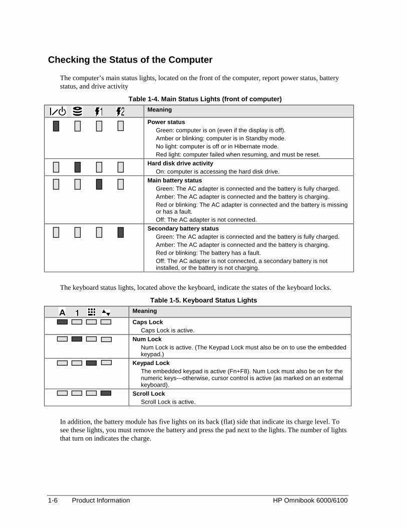
Checking the Status of the Computer
The computer’s main status lights, located on the front of the computer, report power status, batterystatus, and drive activity
Table 1-4. Main Status Lights (front of computer)
Meaning
Power statusGreen: computer is on (even if the display is off).Amber or blinking: computer is in Standby mode.No light: computer is off or in Hibernate mode.Red light: computer failed when resuming, and must be reset.
Hard disk drive activityOn: computer is accessing the hard disk drive.
Main battery statusGreen: The AC adapter is connected and the battery is fully charged.Amber: The AC adapter is connected and the battery is charging.Red or blinking: The AC adapter is connected and the battery is missingor has a fault.Off: The AC adapter is not connected.
Secondary battery statusGreen: The AC adapter is connected and the battery is fully charged.Amber: The AC adapter is connected and the battery is charging.Red or blinking: The battery has a fault.Off: The AC adapter is not connected, a secondary battery is notinstalled, or the battery is not charging.
The keyboard status lights, located above the keyboard, indicate the states of the keyboard locks.
Table 1-5. Keyboard Status Lights
Meaning
Caps LockCaps Lock is active.
Num LockNum Lock is active. (The Keypad Lock must also be on to use the embeddedkeypad.)
Keypad LockThe embedded keypad is active (Fn+F8). Num Lock must also be on for thenumeric keys—otherwise, cursor control is active (as marked on an externalkeyboard).
Scroll LockScroll Lock is active.
In addition, the battery module has five lights on its back (flat) side that indicate its charge level. Tosee these lights, you must remove the battery and press the pad next to the lights. The number of lightsthat turn on indicates the charge.

HP Omnibook 6000/6100 Product Information 1-7
Using Fn Hot Keys
The combination of the Fn key plus another key creates a hot key—a shortcut key sequence—forvarious system controls. To use a hot key, press and hold Fn, press the appropriate second key, thenrelease both keys.
External keyboards support only Fn+F5, Fn+F7, and Fn+F12. To use these, press and hold leftCTRL+left ALT, press the appropriate second key, then release both keys.
Table 1-6. Fn Hot Keys
Hot Key EffectFn+F1 Decreases the display brightness.Fn+F2 Increases the display brightness.Fn+F5 Toggles among the built-in display, an external display, and simultaneous display on
both.Fn+F7 Mutes the computer’s speakers.Fn+F8 Toggles the built-in keypad on and off. Does not affect an external keyboard. If Num
Lock is on, then the numeric functions are active; otherwise, cursor control is active.Fn+F12 Enters Hibernate mode.Fn+NumLock Toggles Scroll Lock on and off.Fn+UP ARROW Increases sound volume (on Omnibook 6000 models only).Fn+DOWN ARROW Decreases sound volume (on Omnibook 6000 models only).

1-8 Product Information HP Omnibook 6000/6100
Resetting the Computer
Occasionally, Windows or the computer may stop responding, so that you cannot turn the computeroff. If this happens, try the following in the order listed:
1. If possible, shut down Windows: press CTRL+ALT+DEL, then click Shut Down. Press the bluesleep button to restart.
2. Slide and hold the power button for 4 seconds, until the display shuts down, then press the bluesleep button to restart.
–or, if this fails–
Insert a straightened paper clip into the system-off switch on the right side of the computer, thenpress the blue sleep button to restart.
Figure 1-4. Resetting the Computer
Note
To boot from a floppy, CD-ROM, or DVD drive in the module bay, insert a bootable CD (such asthe Recovery CD) into the drive, then reboot. Press ESC during reboot when the HP logo andprompt appear, then select the CD-ROM/DVD drive as the temporary boot device.

HP Omnibook 6000/6100 Product Information 1-9
Specifications
The following tables list the specifications for the computer and its accessories. These are subject tochange: for the latest versions, see the HP Notebook Web site (www.hp.com/notebooks).
Table 1-7. Omnibook 6000/6100 Specifications
Physical Attributes Size (14.0-inch display): 315 × 261 × 32 mm (12.4 × 10.3 × 1.3 in).Size (15.1-inch display): 325 × 261 × 34 mm (12.8 × 10.3 × 1.4 in).Weight: 2.3–2.9 kg (5.0–6.4 lb), depending on configuration.Magnesium display cover.
Processor andBus Architecture
Omnibook 6000:550- to 750-MHz Celeron processor with 128-KB four-way set-associative L2 cache.–or–600-, 650-, 700-, 850-, 900-, or 1000-MHz Intel Mobile Pentium III processor withSpeedStep technology with 256-KB four-way set-associative L2 cache.1.6-V core, 2.5-V external, low-power processor.32-KB (16-KB instruction, 16-KB data) L1 cache.32-bit PCI bus.Omnibook 6100:933-, 1000-, or 1133-MHz Intel Mobile Pentium III-M processor with Intel Speed Steptechnology.Integrated 32-KB (16-KB instruction, 16-KB data) L1 cache and 512-KB four-wayset-associative L2 cache.1.4-V core low-power processor with 133-MHz processor system bus.Core logic interfaces processor, system memory, graphics subsystem, 33-MHzsystem PCI bus, and other I/O.
Graphics Omnibook 6000:14.1- or 15.0-inch XGA active-matrix (TFT) display (1024 × 768) or 15.0-inch SXGA+(1400 × 1050).External monitors up to 1600 × 1200 × 64K or 16M colors, and at least 75 Hz refreshrate (only 60 Hz at 1400 × 1050).Zoomed Video support for lower PC Card slot.3D and OpenGL graphics support.Celeron models: ATI Mobility M graphics accelerator with 4-MB display RAM, 2xAGP graphics capability.Pentium III models: ATI Mobility M1 graphics accelerator with 8-MB display RAM, 2xAGP graphics capability.Omnibook 6100:14.1-inch XGA (1024 × 768) or 15.0-inch SXGA+ (1400 × 1050) active-matrix (TFT)LCD display.External monitors up to 1600 × 1200 resolution, 16M (24- or 32-bit) colors, and atleast 75 Hz refresh rate (only 60 Hz at 1400 × 1050).ATI Mobility Radeon graphics accelerator with 16-MB DDR graphics memory, 4xAGP graphics capability.Hardware 3D acceleration, hardware DVD acceleration.Dual display capability (depends on operating system support).Zoomed Video support for lower PC Card slot.
Power Rechargeable lithium-ion battery with LED charge-level gauge (11.1 or 14.8 Vdc).Battery life (one battery): up to 4-5 hours typical with 8-cell Li-Ion 14.8-V battery(varies with model and usage).Fast battery recharge: 80% in 1.5 hour, 100% in 2 hours.Low-battery warning.Suspend/resume capability.Universal 60-watt AC adapter: 100–240 Vac (50/60 Hz) input, 19 Vdc output.Optional secondary battery available for module bay.
1-10 Product Information HP Omnibook 6000/6100
Mass Storage 5- to 30-GB removable hard drive.1.44-MB floppy drive module (on certain models).24x CD-ROM, 6x or 8x DVD, or other drive module.Optional drive modules available.
SDRAM Omnibook 6000:Two slots for PC-100 or higher SDRAM modules.64-MB SDRAM installed in one slot.At least 100-MB RAM preinstalled.Omnibook 6100:Two slots for PC-133 SDRAM modules.Up to 1024-MB RAM maximum.At least 128-MB RAM preinstalled.
Audio System 16-bit Sound Blaster Pro−compatible stereo sound.Stereo sound via two built-in speakers (500 Hz to 10 KHz range).3D-enhanced PCI bus audio with Zoomed Video support.Built-in microphone.Separate audio-off button with indicator light.Headphone-out, microphone-in, and audio line-in.
Keyboard andPointing Device
87/88-key touch-type QWERTY keyboard with 101/102 key emulation.Embedded numeric keypad.Left and right click buttons, center scroll button.12 function (Fn) keys.Two pointing devices: pointing stick and touch pad.Four user-programmable One-Touch buttons (Omnibook 6100 models only).
LAN Ethernet 10Base-T (10 Mbps) and 100Base-TX (100 Mbps) support.Supports wake-on-LAN (Windows 2000), remote wake-up (Windows 98), fast IP,DMI, dRMON.MBA (Managed Boot Agent) support for PXE/BINL, BOOTP, NCP/IPX, DHCP.
Modem Hardware-based controllerless modem (US Robotics or 3Com) or software-basedACLink modem (Ambit), mini-PCI interfaceData speed: 56 Kbps (V.90) maximum.Fax speed: 14.4 Kbps, Class 1 and 2.Modulation: V.21, V.22, V.22bis, V.23, V.32, V.32bis, V.34, V.90, X2 (US Roboticsand 3Com only), Bell 103, Bell 212A.Synchronous transfer: V.80.Compression: V.42bis, MNP5.Error correction: V.42, MNP2-4.Fax: Group 3 fax, Class 1. V.17, V.27ter, V.29, V.21 channel 2.
Wireless LAN(Omnibook 6100models only)
Radio: IEEE 802.11b, WECA Wi-Fi compliant, direct-sequence spread-spectrum.Operating frequency: 2.5-GHz ISM band, exact frequencies and channels depend oncountry.Raw data rate: 1, 2, 5.5, or 11 Mbps.Transmitter output: 15 dBm typical (approx. 30 mW), 16 dBm max (approx.40 mW).Receiver sensitivity: –84 dBm typical.Range: up to 100 m (300 ft) or more, depending on environment and conditions.On-off button and indicator.Mini-PCI interface.
Input/Output Universal serial bus (USB), one or two ports.9-pin, 115,200-bps serial (16550 UART).25-pin bi-directional ECP/EPP parallel.15-pin VGA video-out with DDC support.Dual display.PS/2 keyboard/mouse.4-Mbps IrDA-compliant infrared port.S-video (TV-out) (Omnibook 6100 models only)
Expandability One Type III or two Type II 16-/32-bit PC Card slots (3.3- and 5-V support).CardBus enabled.Plug-in module bay for accessory modules.Optional port replicator, mini dock, and docking system.
HP Omnibook 6000/6100 Product Information 1-11
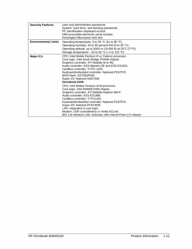
Security Features User and administrator passwords.System, hard drive, and docking passwords.PC identification displayed at boot.DMI-accessible electronic serial number.Kensington Microsaver lock slot.
Environmental Limits Operating temperature: 5 to 35 °C (41 to 95 °F).Operating humidity: 20 to 90 percent RH (5 to 35 °C).Operating altitude: up to 3000 m (10,000 ft) at 25°C (77°F).Storage temperature: –20 to 50 °C (–4 to 122 °F).
Major ICs CPU: Intel Mobile Pentium III or Celeron processor.Core logic: Intel South Bridge PIIX4M chipset.Graphics controller: ATI Mobility M or M1.Audio controller: ESS Maestro-3E and ESS ES1921.CardBus controller: TI PCI 1420.Keyboard/embedded controller: National PC87570.BIOS flash: SST28SF040.Super I/O: National NS97338.Omnibook 6100:CPU: Intel Mobile Pentium III-M processor.Core logic: Intel 830M/ICH3M chipset.Graphics controller: ATI Mobility Radeon M6-P.Audio controller: ESS ES1988.CardBus controller: TI PC1420.Keyboard/embedded controller: National PC87570.Super I/O: National PC87393F.LAN: integrated in core logic.Modem: USR controllerless or Ambit ACLink.802.11b wireless LAN: Actiontec with Intersil Prism 2.5 chipset.

1-12 Product Information HP Omnibook 6000/6100
Table 1-8. Omnibook 6000/6100 Accessories
Accessory Description Omnibook6100
Omnibook6000
Omnibook500
MemoryF1456B 32-MB SDRAM module (PC100) • •F1457B 64-MB SDRAM module (PC100) • •F1457C 64-MB SDRAM module (PC133) • • •F1622B 128-MB SDRAM module (PC100) • •F1622C 128-MB SDRAM module (PC133) • •F1654A 256-MB SDRAM module (PC100) • •F1654C 256-MB SDRAM module (PC133) • •F3495A 128-MB SDRAM module (PC133) •F3496A 256-MB SDRAM module (PC133) •F2298A 512-MB SDRAM module (PC133) •
Hard DrivesF2018B 20-GB hard disk drive module • • •F2018C 30-GB hard disk drive module • • •F2016B 20-GB hard disk drive module •F2016C 30-GB hard disk drive replacement •F2295A 30-GB hard disk drive replacement •
Plug-in ModulesF2008A Floppy disk drive cable (external) • •F2009A Zip drive • • •F2013A Floppy disk drive module • • •F2015A DVD drive module • • •F2017A CD-ROM drive module • • •F2022A/B SuperDisk drive module • • •F2026A CD read/write drive module • • •F2101A USB floppy disk drive cable • •F2107A DVD-ROM/CD-RW drive module • • •
Power OptionsF1454A 60-watt AC adapter • • •F1455A 75-watt auto/airline power adapter • • •F1781A UltraSlim AC Adapter • • •F2011A Battery charger (external) • • •F2014A Lithium-ion secondary battery • • •F2019A Lithium-ion primary battery • •F2297A Auto power adapter (Europe only, 24 V) • • •8120-63128120-63138120-63148120-63168121-07028120-63178120-83678120-83738120-84528120-8699
Replacement power cord (Australia)Replacement power cord (U.S., Canada, Taiwan)Replacement power cord (Europe)Replacement power cord (Japan)Replacement power cord (India)Replacement power cord (South Africa)Replacement power cord (Argentina)Replacement power cord (People’s Rep. of China)Replacement power cord (Chile)Replacement power cord (Hong Kong, Singapore,U.K.)
• • •
AdaptersF1469A PS/2 Y adapter • •

HP Omnibook 6000/6100 Product Information 1-13
Accessory Description Omnibook6100
Omnibook6000
Omnibook500
PC CardsF1623A 10/100-Mbps Ethernet + 56-Kbps modem PC Card
by Xircom• • •
F1625A 56-Kbps global modem PC Card by Xircom • • •F1626A/B 10/100-Mbps Ethernet PC Card by 3Com • •F1627A 56-Kbps US modem PC Card by Xircom • • •F1643A/B Realport 10/100-Mbps Ethernet + 56-Kbps modem
PC Card by Xircom• •
F1782A 10/100-Mbps Ethernet + 56-Kbps modem PC Cardby 3Com
• • •
F1985A 10/100-Mbps USB-Ethernet adapter by 3Com • • •F2135A/B 802.11b wireless LAN access point • • •F2136A/B 802.11b wireless LAN PC Card • • •F2196A Bluetooth PC Card by 3Com • • •
DockingF1451A/B Port replicator • •F1452A/B Mini dock • •F1453A Monitor stand (short) for F1451A and F1452A • •F1477A/B Docking system and monitor stand (tall) • •F2012A Docking tray • •F2021A Docking module bay adapter • •
1-14 Product Information HP Omnibook 6000/6100
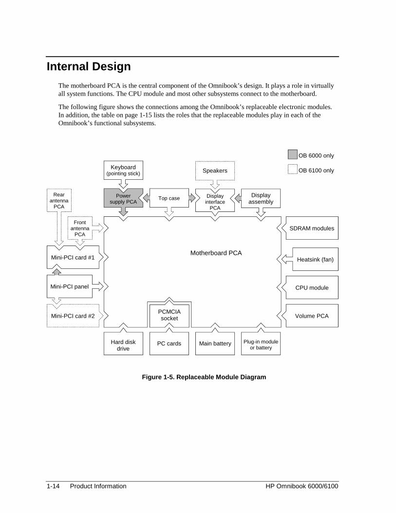
Internal Design
The motherboard PCA is the central component of the Omnibook’s design. It plays a role in virtuallyall system functions. The CPU module and most other subsystems connect to the motherboard.
The following figure shows the connections among the Omnibook’s replaceable electronic modules.In addition, the table on page 1-15 lists the roles that the replaceable modules play in each of theOmnibook’s functional subsystems.
Figure 1-5. Replaceable Module Diagram
Motherboard PCAHeatsink (fan)
CPU module
Volume PCA
Hard diskdrive
Mini-PCI card #1
Top casePowersupply PCA
Displayinterface
PCA
Displayassembly
Keyboard(pointing stick) Speakers
SDRAM modules
Rearantenna
PCA
Frontantenna
PCA
Mini-PCI panel
Mini-PCI card #2
PC cards
PCMCIAsocket
Main battery Plug-in moduleor battery
OB 6000 only
OB 6100 only

HP Omnibook 6000/6100 Product Information 1-15
Table 1-9. Functional StructureBootup CPU module
MotherboardPower supply PCA (OB 6000)Floppy disk moduleHard disk drive
Main processor (MMO).Primary system circuitry, system BIOS (OB 6100).System BIOS (OB 6000).First source of disk-based startup code.Second source of disk-based startup code.
Processor CPU moduleMotherboard
Main processor, numeric data processor, L1 and L2 cache.Primary system circuitry.
Memory MotherboardSDRAM module
No onboard RAM, video RAM.Changeable RAM (2 slots).
Power BatteryMotherboard
Power supply PCA (OB 6000)AC adapter
Power storage.AC adapter socket, power switch, lid switch, system-off switch,power supply, power control circuitry (OB 6100).Power control circuitry (OB 6000).AC-to-DC converter.
Display MotherboardDisplay assemblyDisplay interface PCA
Graphics controller, ZV controller, video RAM.Display output, backlight, power converter for backlight.Display identification DIP switches.
Hard disk MotherboardHard disk drive
Hard disk controller.Hard disk mechanism.
Floppy drive MotherboardFloppy disk module
I/O controller, floppy connector.Floppy disk mechanism.
Keyboard MotherboardPower supply PCA (OB 6000)Keyboard
Keyboard BIOS (OB 6100), keyboard controller (OB 6100).Keyboard controller, keyboard BIOS (OB 6000).Key switches.
Pointer MotherboardPower supply PCA (OB 6000)KeyboardTop case
Keyboard circuitry, keyboard controller (OB 6100).Keyboard controller (OB 6000), keyboard BIOS (OB 6000).Pointing stick sensor.Touch pad sensor, click buttons, controller (PS/2 output).
Audio MotherboardDisplay interface PCAVolume PCATop caseSpeaker assembly (OB 6100)
Audio controller, audio decoder, speaker amplifier, ZV controller.Microphone.External audio jacks, headphone amplifier, audio-off switch.Speakers (OB 6000).Speakers (OB 6100).
Status MotherboardPower supply PCA (OB 6000)Display interface PCATop case
LED circuitry, keyboard controller (OB 6100).Keyboard controller (OB 6000).Keyboard LEDs.Main status LEDs.
Serial Motherboard I/O controller, serial connector.Parallel Motherboard I/O controller, parallel connector.Infrared Motherboard I/O controller, infrared transmitter/receiver.PS/2 port Motherboard
Power supply PCA (OB 6000)PS/2 connector, keyboard controller (OB 6100).Keyboard controller (OB 6000).
USB Motherboard Bus controller (South Bridge), USB connector.Docking port Motherboard Docking logic, docking connector.PCMCIA Motherboard
PCMCIA socketPCMCIA controller.PCMCIA connectors.
WirelessLAN
MotherboardFront antenna PCARear antenna PCAMini-PCI card #1
I/O controller.Receive antenna, on-off button, indicator light.Transmit/receive antenna.Radio, radio frequency circuitry.
LAN MotherboardMini-PCI card #1Mini-PCI panel
LAN circuitry (OB 6100), bus controller.LAN circuitry (OB 6000).LAN connector.
Modem Mini-PCI card #1Mini-PCI card #2 (OB 6100)Mini-PCI panel
Modem circuitry (OB 6000).Modem circuitry (OB 6100).Modem connector.


HP Omnibook 6000/6100 Removal and Replacement 2-1
2
Removal and Replacement
This chapter tells you how to remove and replace the Omnibook’s removable components andassemblies. The items marked by • in the following table are user-replaceable.
Table 2-1. Removal Cross-Reference • Battery, main (page 2-4).
Battery, CMOS (page 2-34). • Bumpers, display (page 2-12) • Cap, pointing stick (page 2-12). • Card, mini-PCI #1 (page 2-9).
Card, mini-PCI #2 (page 2-34).Case, bottom (page 2-22).Case, top (page 2-20).Cover, center hinge (page 2-34).
• Cover, left corner (page 2-12).Cover, left hinge (page 2-34).
• Cover, mini-PCI (page 2-12). • Cover, SDRAM (page 2-12). • Cover, right corner (page 2-12).
Cover, right hinge (page 2-34). • Covers, screw (page 2-12).
CPU module (page 2-19).Display assembly (page 2-12).Doors, docking (page 2-27).Doors, PCMCIA (page 2-27).
• Drive, hard disk (page 2-7). • Feet, rubber (page 2-12).
Heatsink (with fan) (page 2-17).Keyboard (page 2-15).Panel, sound/IR (page 2-34).Panel, mini-PCI (page 2-34).
• Panel, power button (page 2-11).Panel, vent (page 2-34).PCA, display interface (page 2-34).PCA, power supply (page 2-34).PCA, motherboard (page 2-22).PCA, volume (page 2-34).PCA, front antenna (page 2-34).PCA, rear antenna (page 2-34).
• Plug-in module (page 2-5). • SDRAM module (page 2-6).
Socket, PCMCIA (page 2-34).Speaker assembly (page 2-28).
• Tray, hard disk drive (page 2-7).
Caution Always provide proper grounding when performing repairs. Without propergrounding, an electrostatic discharge can damage the Omnibook and itscomponents.
Notes
Reassembly steps are the reverse of the removal steps. Reassembly notes are included at the endof each section below.
Symbols like this throughout this chapter show approximate full-size screw outlines. You canuse these to verify the sizes of screws before you install them. Installing a wrong-size screw candamage the unit. (The symbol at the left represents an M2.5×5mm T-head screw.)

2-2 Removal and Replacement HP Omnibook 6000/6100
Table 2-2. Required Equipment
• Small Phillips screwdriver, preferably magnetized.
• Small flat-blade screwdriver.
• IC (PLCC) removal tool (similar to OK Industries EX-5).
Table 2-3. Recommended Screw Torques
Screw Thread Size Torque (cm-kgf) Torque (in-lbf)M2 1.3 – 1.8 1.1 – 1.5
M2.5 (2–11 mm long) 3.0 – 3.5 2.6 – 3.0M2.5 (12–19 mm long) 2.5 – 3.0 2.2 – 2.6
M3 3.0 – 3.5 2.6 – 3.0
Disassembly Flowchart
The following diagram shows the general “path” you will use in disassembling the computer to accessany particular component.

HP Omnibook 6000/6100 Removal and Replacement 2-3
Figure 2-1. Disassembly Flow
Battery, AC adapter, secondary battery
Plug-in module, hard disk drive *
Power button panel
Keyboard
Heatsink (with fan)
Display assembly
Top case
*Only if removing the top case,motherboard, or bottom case.
If removing onlydisplay assembly or
hinge coversCPU module
CMOS battery
Hinge covers
Rear antenna PCA (wireless only)
PCMCIA socket
Display interface PCA
Power supply PCA (OB 6000 only)
Volume PCA
Mini-PCI panel
Vent panel (Omnibook 6000 only)
Sound/IR panel
Docking doors
PCMCIA doors
Speaker assembly (OB 6100 only)
Motherboard or bottom case Front antenna PCA (wireless only)
Mini-PCI card #2 (OB 6100 only)

2-4 Removal and Replacement HP Omnibook 6000/6100
Removing the Battery(User-Replaceable)
Required Equipment
• None.
Removal Procedure
• Slide the battery’s release latch, then lift the battery out of its compartment.
Figure 2-2. Removing the Battery
Reassembly Notes
• Insert the front (rounded) end of the battery into the battery compartment on the bottom of thecomputer, and lower the back end in until it clicks into place.

HP Omnibook 6000/6100 Removal and Replacement 2-5
Removing a Plug-In Module(User-Replaceable)
Required Equipment
• None.
Removal Procedure
1. Press the button on the module release latch, and slide the latch toward the front of the computer.
Figure 2-3. Removing a Module
2. Grasp the module and pull it out.
Figure 2-4. Removing a Module
2-6 Removal and Replacement HP Omnibook 6000/6100
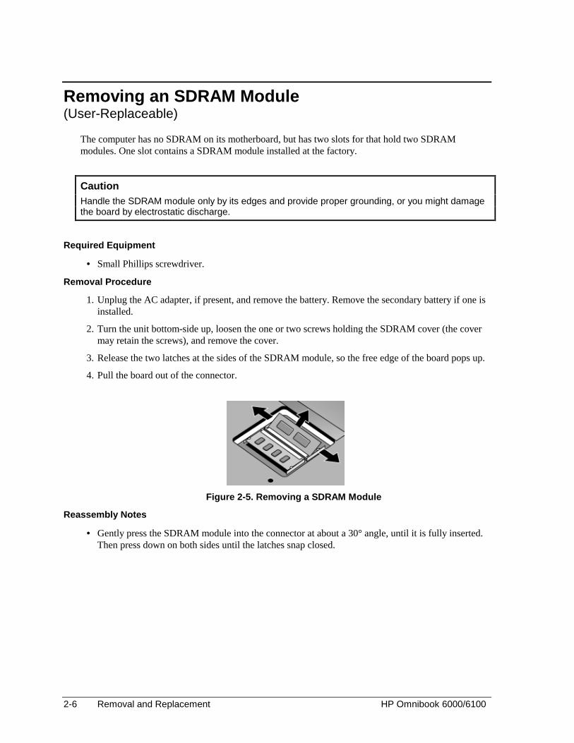
Removing an SDRAM Module(User-Replaceable)
The computer has no SDRAM on its motherboard, but has two slots for that hold two SDRAMmodules. One slot contains a SDRAM module installed at the factory.
Caution Handle the SDRAM module only by its edges and provide proper grounding, or you might damagethe board by electrostatic discharge.
Required Equipment
• Small Phillips screwdriver.
Removal Procedure
1. Unplug the AC adapter, if present, and remove the battery. Remove the secondary battery if one isinstalled.
2. Turn the unit bottom-side up, loosen the one or two screws holding the SDRAM cover (the covermay retain the screws), and remove the cover.
3. Release the two latches at the sides of the SDRAM module, so the free edge of the board pops up.
4. Pull the board out of the connector.
Figure 2-5. Removing a SDRAM Module
Reassembly Notes
• Gently press the SDRAM module into the connector at about a 30° angle, until it is fully inserted.Then press down on both sides until the latches snap closed.
HP Omnibook 6000/6100 Removal and Replacement 2-7
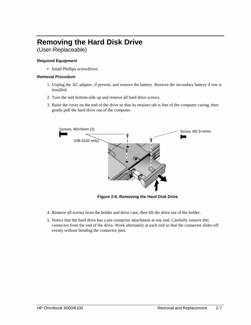
Removing the Hard Disk Drive(User-Replaceable)
Required Equipment
• Small Phillips screwdriver.
Removal Procedure
1. Unplug the AC adapter, if present, and remove the battery. Remove the secondary battery if one isinstalled.
2. Turn the unit bottom side up and remove all hard drive screws.
3. Raise the cover on the end of the drive so that its retainer tab is free of the computer casing, thengently pull the hard drive out of the computer.
Figure 2-6. Removing the Hard Disk Drive
4. Remove all screws from the holder and drive case, then lift the drive out of the holder.
5. Notice that the hard drive has a pin connector attachment at one end. Carefully remove thisconnector from the end of the drive. Work alternately at each end so that the connector slides offevenly without bending the connector pins.
Screw, M2.5×4mmScrews, M3×6mm (2)
(OB 6100 only)
2-8 Removal and Replacement HP Omnibook 6000/6100
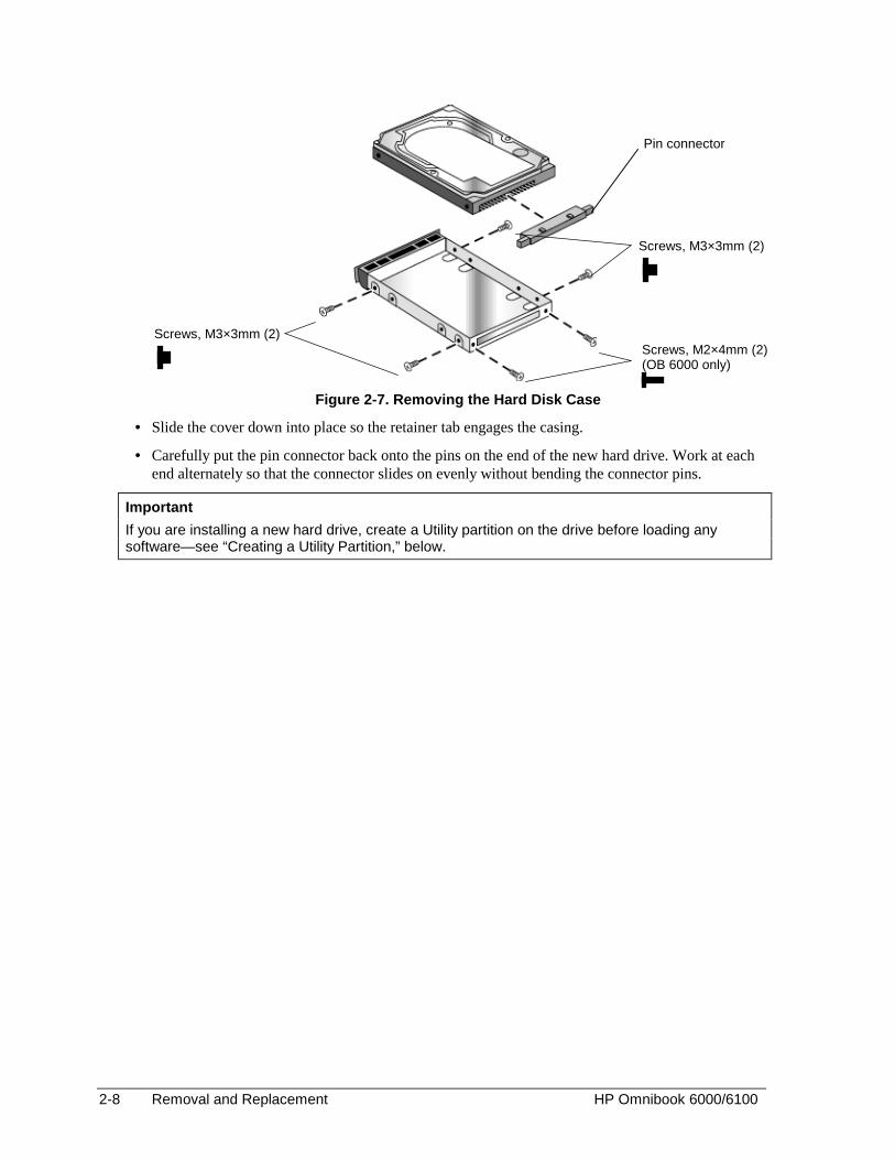
Figure 2-7. Removing the Hard Disk Case
• Slide the cover down into place so the retainer tab engages the casing.
• Carefully put the pin connector back onto the pins on the end of the new hard drive. Work at eachend alternately so that the connector slides on evenly without bending the connector pins.
Important
If you are installing a new hard drive, create a Utility partition on the drive before loading anysoftware—see “Creating a Utility Partition,” below.
Pin connector
Screws, M3×3mm (2)
Screws, M3×3mm (2)Screws, M2×4mm (2)(OB 6000 only)
HP Omnibook 6000/6100 Removal and Replacement 2-9
Creating a Utility Partition
When you install a new hard drive, always create a Utility partition on the drive before loading anysoftware.
1. Insert the Recovery CD in the CD-ROM drive. To open the drive when the computer is turned off,insert a straightened paper clip into the hole on the front of the drive.
2. Restart the computer. If the computer is running, click Start, Shut Down, Restart.
3. When you see the HP logo, press ESC.
4. Select the CD or DVD drive as the boot device.
5. When the Recovery CD dialog box appears, follow the displayed instructions. If prompted, acceptthe recommended partition size. If you install the factory software, the recovery process can takeup to 10 minutes.
If you want to create the Utility partition without installing the factory software, click Advancedand select the option to not install the operating system.
If your hard disk is partitioned into several drives, you can install the factory software on drive Cwithout affecting other drives. Click Advanced and select to restore only the C partition.
6. When prompted to reboot the computer, press CTRL+ALT+DEL and follow any instructions thatappear onscreen.

2-10 Removal and Replacement HP Omnibook 6000/6100
Removing Mini-PCI Card #1(User-Replaceable)
Certain computers include a mini-PCI card. Omnibook 6100 models may have a second mini-PCI card.See the table on page 2-34.
Caution Handle the mini-PCI card only by its edges and provide proper grounding, or you might damage theboard by electrostatic discharge.
Required Equipment
• Small Phillips screwdriver.
Removal Procedure
1. Unplug the AC adapter, if present, and remove the battery. Remove the secondary battery if one isinstalled.
2. Loosen the screw holding the mini-PCI cover (the cover retains the screw), and remove the cover.
Caution Be gentle when removing and attaching antenna cables from the mini-PCI card. Damage to cablesor connectors can degrade performance.
3. Detach all the cables from the board.
4. Release the latches at the sides of the board, so that the free edge of the board pops up.
5. Gently pull the board out of its connector.
Figure 2-8. Removing the Mini-PCI Card
Reassembly Notes
• Gently press the mini-PCI card into the connector at about a 30° angle, until it is fully inserted.Then press down on both sides until the latches snap closed.

HP Omnibook 6000/6100 Removal and Replacement 2-11
Removing the Power Button Panel(User-Replaceable)
Required Equipment
• Small flat-blade screwdriver.
Removal Procedure
1. Unplug the AC adapter, if present, and remove the battery. Remove the secondary battery if one isinstalled.
2. Carefully insert the screwdriver blade under the power button panel along the edge shown below,and gently pry up the center of the cover.
3. Insert a thumb or finger under the center of the panel, and lift the panel out.
Figure 2-9. Removing the Power Button Panel
Reassembly Notes
• Insert the left end of the panel into the top case, and press the panel into place.

2-12 Removal and Replacement HP Omnibook 6000/6100
Replacing Small Parts(User-Replaceable)
The user can replace the following small parts.
Table 2-4. Replacing Small Parts (User-Replaceable)
Part Replacement Procedure
Cap, pointing stick Pull the cap off the pointing stick.
Bumpers, display (ondisplay bezel)
Insert a small flat-blade screwdriver under the bumper and pry it loose. To replace,firmly press the adhesive side of the bumper into the recess.
Cover, mini-PCI On the bottom of the computer, loosen the screw in the mini-PCI cover (the coverretains the screw) and remove the cover.
Cover, SDRAM On the bottom of the computer, loosen the one or two screws in the SDRAM modulecover (the cover may retain the screws) and remove the cover.
Covers, screw (ondisplay bezel)
Insert a small flat-blade screwdriver under the cover and pry it loose. To replace,firmly press the adhesive side of the cover into the recess.
Covers, left/rightcorner
From the bottom of the computer, remove the screws holding the corner covers, thenremove the covers.
Feet, rubber (onbottom of unit)
Insert a small flat-blade screwdriver under the foot and pry it loose. To replace, firmlypress the adhesive side of the foot into the recess.

HP Omnibook 6000/6100 Removal and Replacement 2-13
Removing the Display Assembly(HP Authorized Service Providers Only)
Required Equipment
• Small Phillips screwdriver.
Removal Procedure
1. Unplug the AC adapter, if present, and remove the battery. Remove the secondary battery if one isinstalled.
2. Remove the power button panel (page 2-11).
3. From the back of the computer, remove the two screws near the PS/2 keyboard/mouse port, and thetwo near the AC adapter jack.
4. From the bottom of the computer, remove the two screws from the rear corners (closest to the backedge).
5. Open the display. Remove the screw from the display’s ground wire, and disconnect the maincable.
6. Remove any screws from the center hinge cover, and from the left and right hinges.
7. Lift the display off of the computer.

2-14 Removal and Replacement HP Omnibook 6000/6100
Figure 2-10. Removing the Display
Reassembly Notes
• Before installing any screws, make sure the center hinge cover fits over the tab in the bottom case.
Important
• Make sure the DIP switches on the display interface PCA match the settings shown on thelabel on the display cable, or you risk damaging the display.
• Omnibook 6100: Reprogram the BIOS IC, preferably with the latest BIOS for displaycompatibility.
• Omnibook 6000: If you change the DIP switches, use the service utilities disk to reprogramthe EEPROM—see page 2-31. If the EEPROM is not programmed correctly, the display willnot turn on.
Screws,M2.5×6mm (5)
Screws, M2.5×8mm (2)(OB 6100)
Screws, M2.5×6mm (2)(OB 6000)
Screws, M2.5×4 mm(1 on OB 6100 models,2 on some OB 6000 models)
Label with DIPswitch settings
Screw, M2.5×17mm (OB 6100)
Screw, M2.5 x 6mm (OB 6000)
Screw, M2.5×5mm
HP Omnibook 6000/6100 Removal and Replacement 2-15
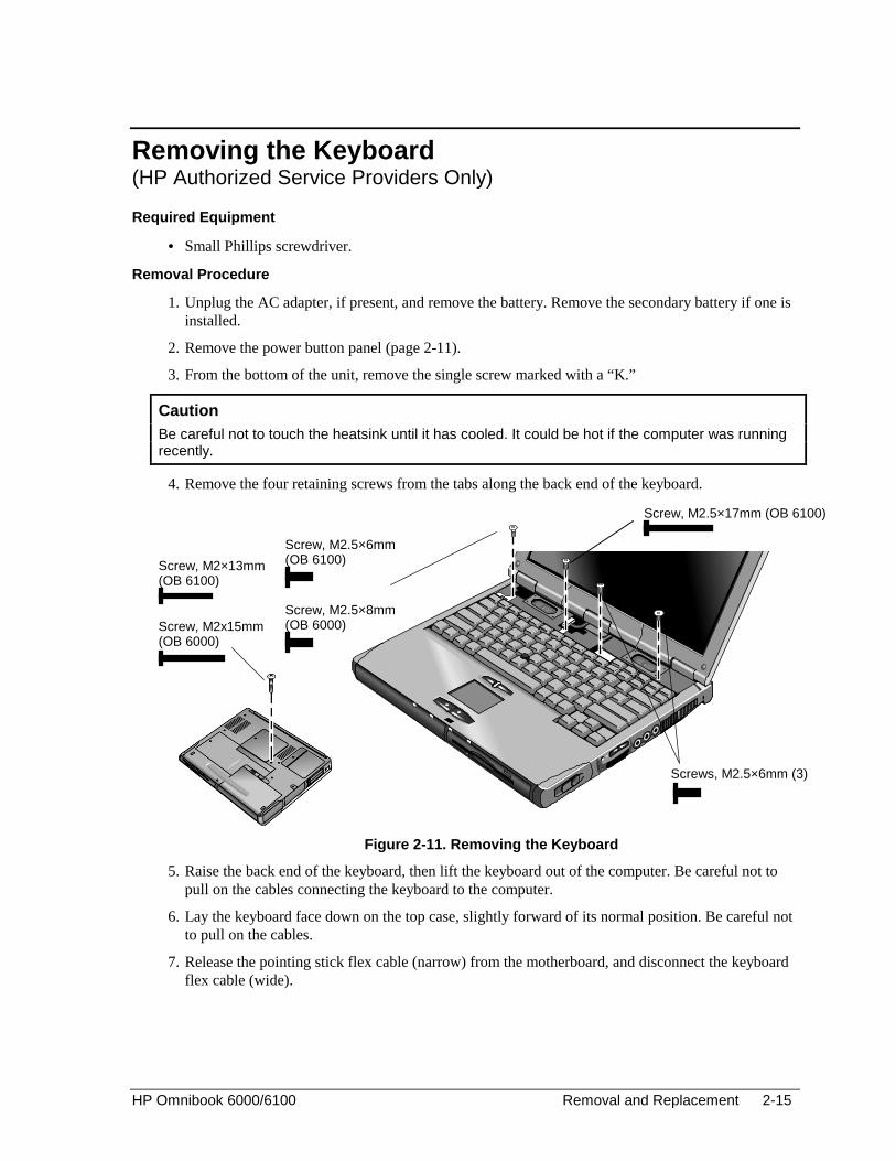
Removing the Keyboard(HP Authorized Service Providers Only)
Required Equipment
• Small Phillips screwdriver.
Removal Procedure
1. Unplug the AC adapter, if present, and remove the battery. Remove the secondary battery if one isinstalled.
2. Remove the power button panel (page 2-11).
3. From the bottom of the unit, remove the single screw marked with a “K.”
Caution Be careful not to touch the heatsink until it has cooled. It could be hot if the computer was runningrecently.
4. Remove the four retaining screws from the tabs along the back end of the keyboard.
Figure 2-11. Removing the Keyboard
5. Raise the back end of the keyboard, then lift the keyboard out of the computer. Be careful not topull on the cables connecting the keyboard to the computer.
6. Lay the keyboard face down on the top case, slightly forward of its normal position. Be careful notto pull on the cables.
7. Release the pointing stick flex cable (narrow) from the motherboard, and disconnect the keyboardflex cable (wide).
Screws, M2.5×6mm (3)
Screw, M2.5×6mm(OB 6100)
Screw, M2.5×8mm(OB 6000)
Screw, M2×13mm(OB 6100)
Screw, M2x15mm(OB 6000)
Screw, M2.5×17mm (OB 6100)
2-16 Removal and Replacement HP Omnibook 6000/6100
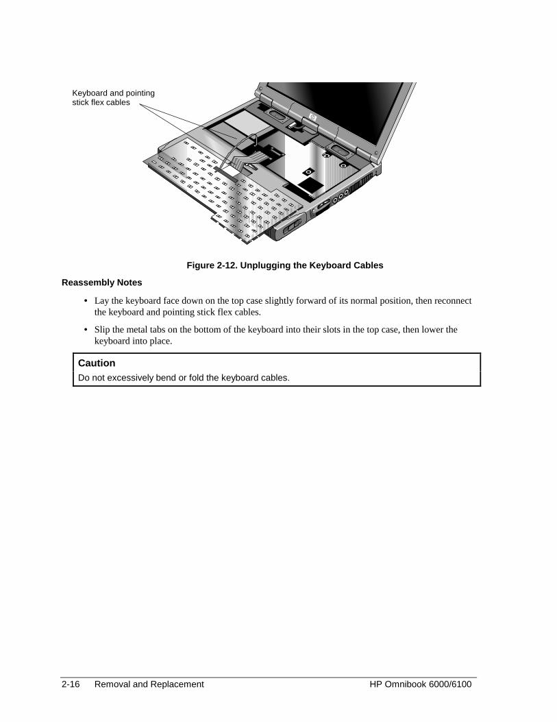
Figure 2-12. Unplugging the Keyboard Cables
Reassembly Notes
• Lay the keyboard face down on the top case slightly forward of its normal position, then reconnectthe keyboard and pointing stick flex cables.
• Slip the metal tabs on the bottom of the keyboard into their slots in the top case, then lower thekeyboard into place.
Caution Do not excessively bend or fold the keyboard cables.
Keyboard and pointingstick flex cables

HP Omnibook 6000/6100 Removal and Replacement 2-17
Removing the Heatsink (with Fan)(HP Authorized Service Providers Only)
Required Equipment
• Small Phillips screwdriver.
Removal Procedure
1. Unplug the AC adapter, if present, and remove the battery. Remove the secondary battery if one isinstalled.
2. Remove these additional assemblies:
• Power button panel (page 2-11).
• Keyboard (page 2-15).
3. Disconnect the fan cable through the opening in the heatsink.
4. Remove the five retaining screws.
5. Lift the heatsink out of the unit.
Figure 2-13. Removing the Heatsink
Screws, M2.5×6mm (4)
Fan cable
Fan cable socket
Screw, M2.5×4mm
Omnibook 6000heatsink
Omnibook 6100heatsink
Screws, M2.5×6mm (5)
See the Cautionon next pagebefore reinstalling.

2-18 Removal and Replacement HP Omnibook 6000/6100
Reassembly Notes
• Tighten screws around the CPU as denoted on the heatsink assembly.
• When installing a new heatsink, use the thin heatsink when the bottom case has a circular vent. Usethe thick heatsink with all other bottom cases.
• If the power supply PCA has a metal cover on it, ensure that there is not a spacer pad in the samelocation on the heatsink. If both are present, remove the spacer pad.
Caution Restore proper thermal contact when installing the heatsink. Otherwise, performance can besignificantly degraded.
Carefully clean the heatsink and CPU surfaces and install a new thermal pad on the heatsink inthese situations:
• Required whenever you install a new CPU for any model.
• Required whenever you remove the heatsink from an Omnibook 6000 with an 800-MHz orfaster CPU.
• Recommended whenever you remove the heatsink from any other model.

HP Omnibook 6000/6100 Removal and Replacement 2-19
Removing the CPU Module(HP Authorized Service Providers Only)
Required Equipment
• Small Phillips screwdriver.
• Small flat-blade screwdriver.
Removal Procedure
1. Unplug the AC adapter, if present, and remove the battery. Remove the secondary battery if one isinstalled.
2. Remove these additional assemblies:
• Power button panel (page 2-11).
• Keyboard (page 2-15).
• Heatsink (page 2-17).
3. Turn the lock screw one-half turn counterclockwise to release the CPU module, and remove theCPU module from the motherboard.
Figure 2-14. Removing the CPU Module
CPU modulelock screw
CPU module(screw placementvaries among models)
Power-levelDIP switches(Omnibook6000 modelsonly)
2-20 Removal and Replacement HP Omnibook 6000/6100
Reassembly Notes
• Carefully insert the CPU module into the motherboard, and turn the lock screw one-half turnclockwise to secure the CPU module.
• The CPU module is keyed for installation, and can only be inserted one way.
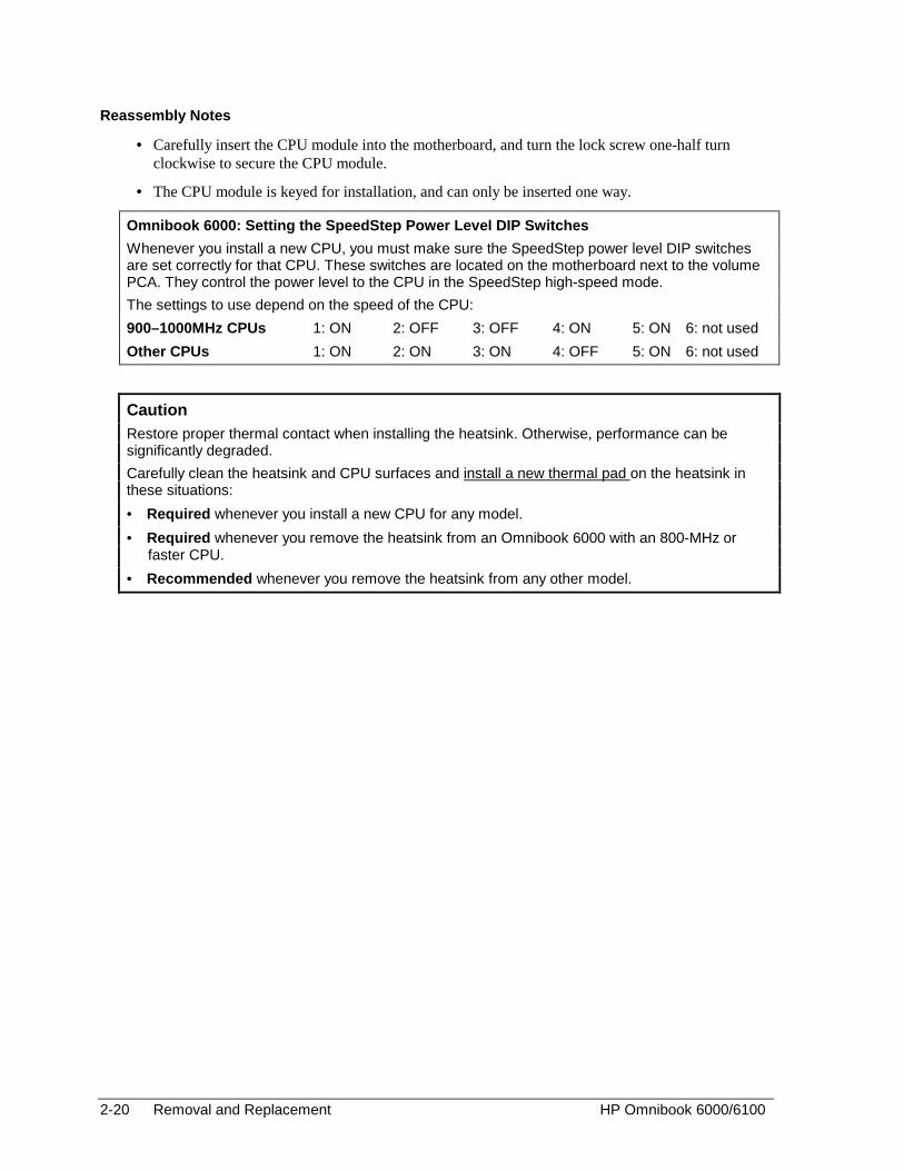
Omnibook 6000: Setting the SpeedStep Power Level DIP Switches
Whenever you install a new CPU, you must make sure the SpeedStep power level DIP switchesare set correctly for that CPU. These switches are located on the motherboard next to the volumePCA. They control the power level to the CPU in the SpeedStep high-speed mode.
The settings to use depend on the speed of the CPU:
900–1000MHz CPUs 1: ON 2: OFF 3: OFF 4: ON 5: ON 6: not used
Other CPUs 1: ON 2: ON 3: ON 4: OFF 5: ON 6: not used
Caution Restore proper thermal contact when installing the heatsink. Otherwise, performance can besignificantly degraded.
Carefully clean the heatsink and CPU surfaces and install a new thermal pad on the heatsink inthese situations:
• Required whenever you install a new CPU for any model.
• Required whenever you remove the heatsink from an Omnibook 6000 with an 800-MHz orfaster CPU.
• Recommended whenever you remove the heatsink from any other model.
HP Omnibook 6000/6100 Removal and Replacement 2-21
Removing the Top Case(HP Authorized Service Providers Only)
Required Equipment
• Small Phillips screwdriver.
Removal Procedure
All Models
1. Unplug the AC adapter, if present, and remove the battery. Remove the secondary battery if one isinstalled.
2. Remove these additional assemblies:
• Power button panel (page 2-9).
• Keyboard (page 2-15).
• Heatsink (page 2-17).
• Display assembly (page 2-13).
• Plug-in module (page 2-5).
• Hard disk drive (page 2-7).
3. From the bottom of the computer, remove the screws holding the left and right corner covers, thenremove the covers.
Hint
The right corner cover may come off more easily if you slide the plug-in module latch forward.
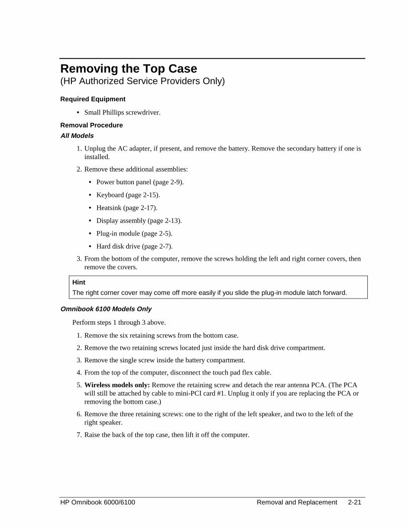
Omnibook 6100 Models Only
Perform steps 1 through 3 above.
1. Remove the six retaining screws from the bottom case.
2. Remove the two retaining screws located just inside the hard disk drive compartment.
3. Remove the single screw inside the battery compartment.
4. From the top of the computer, disconnect the touch pad flex cable.
5. Wireless models only: Remove the retaining screw and detach the rear antenna PCA. (The PCAwill still be attached by cable to mini-PCI card #1. Unplug it only if you are replacing the PCA orremoving the bottom case.)
6. Remove the three retaining screws: one to the right of the left speaker, and two to the left of theright speaker.
7. Raise the back of the top case, then lift it off the computer.

2-22 Removal and Replacement HP Omnibook 6000/6100
Figure 2-15. Removing the Top Case: Omnibook 6100 Models
Omnibook 6000 Models Only
Perform steps 1 through 3 at the beginning of this topic.
1. Remove the five retaining screws from the bottom case.
2. Remove the two retaining screws located just inside the hard disk drive compartment.
3. Remove the single screw inside the battery compartment.
4. From the top of the computer, disconnect the speaker wires and the touch pad flex cable.
5. Remove both retaining screws: one to the left of the right speaker, and one to the right of the touchpad flex cable.
6. Remove the screw from the tab near the upper click buttons.
7. Raise the back of the top case, then lift it off the computer.
Screws,M2.5x4mm (2)
PCMCIA doors
Screws,M2.5x8mm (4)
Screws, M2.5x4mm (2) Cover,right corner
Panel,sound/IR
Cover, leftcorner
Screw, M2.5x2mm
Docking doors
Touch padflex cable
Screws,M2.5x6mm (3)
Screw,M2.5x17mm
Screw, M2.5x6mm (2)
Screw,M2.5x4mm

HP Omnibook 6000/6100 Removal and Replacement 2-23
Figure 2-16. Removing the Top Case: Omnibook 6000 Models
Reassembly Notes: All Models
• Omnibook 6000 only: If you need to reinstall the sound/IR panel, make sure the volume control isoriented properly (pins facing inward). Insert the tabs on the end of the panel into the slots in thebottom case.
• When reinstalling the right corner cover, first insert the tab at the back end of the cover into thecase, then move the plug-in module latch forward and snap the cover over the latch and into place.
• Wireless models only: If you are replacing the rear antenna PCA, place the PCA in its positionnear the left hinge, replace the screw, then thread the cable through to the bottom of the computerand reconnect the cable to the mini-PCI card.
Caution: Omnibook 6000 Models Be careful not to pinch the speaker wires when reinstalling the nearby retaining screws.
Screws,M2.5x6mm (2)
PCMCIA doors
Screws, M2.5x6mm (3)
Screws, M2.5x4mm (2)
Cover,right corner
Panel,sound/IR
Panel,vent
Cover, leftcorner
Screw, M2.5x2mmDocking doors
Touch padflex cable
Screws,M2.5x6mm (3)
2-24 Removal and Replacement HP Omnibook 6000/6100
Removing the Motherboard or Bottom Case(HP Authorized Service Providers Only)
Required Equipment
• Small Phillips screwdriver.
• Small flat-blade screwdriver.
Removal Procedure
All Models
Note: When Replacing the Motherboard If the motherboard is able to boot with the service utility boot disk (see page 2-31), you need totransfer data by running the utility disk. Further information is located on the disk.
1. Unplug the AC adapter, if present, and remove the battery. Remove the secondary battery if one isinstalled.
2. Remove these additional assemblies:
• Plug-in module (page 2-5).
• Hard disk drive (page 2-7).
• Power button panel (page 2-11).
• Keyboard (page 2-15).
• Heatsink (page 2-17).
• Display assembly (page 2-13).
• Top case (page 2-20).
• SDRAM module (page 2-6)
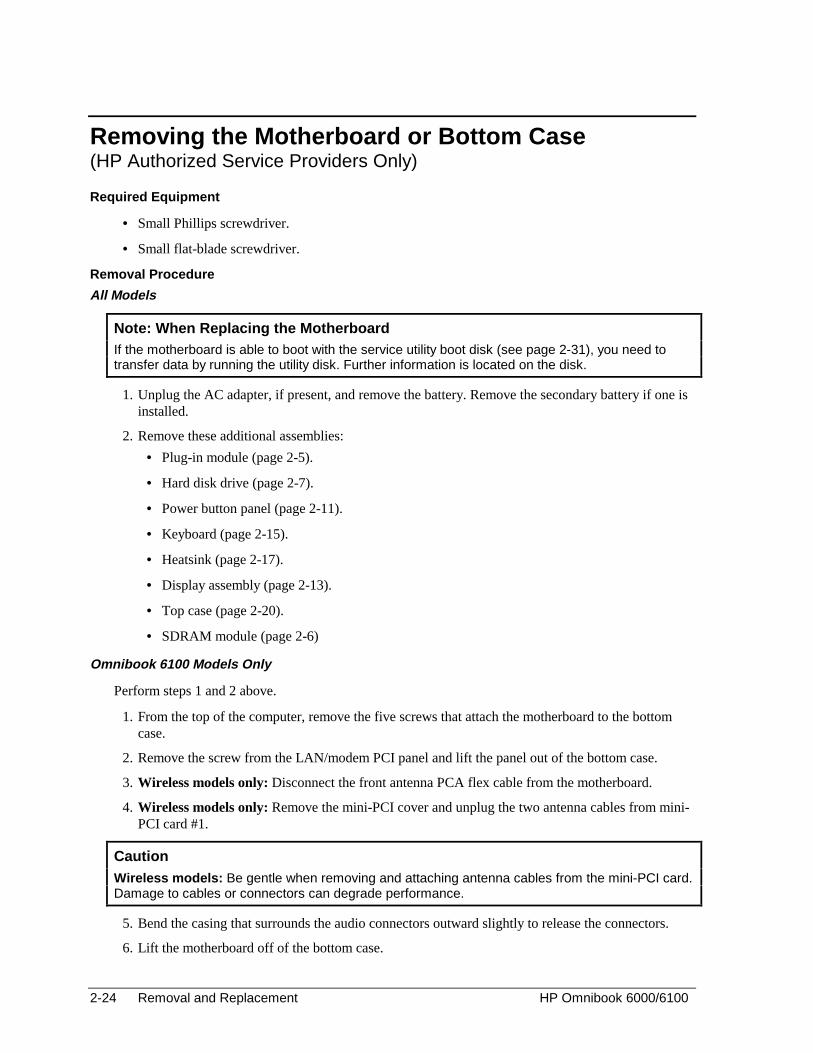
Omnibook 6100 Models Only
Perform steps 1 and 2 above.
1. From the top of the computer, remove the five screws that attach the motherboard to the bottomcase.
2. Remove the screw from the LAN/modem PCI panel and lift the panel out of the bottom case.
3. Wireless models only: Disconnect the front antenna PCA flex cable from the motherboard.
4. Wireless models only: Remove the mini-PCI cover and unplug the two antenna cables from mini-PCI card #1.
Caution Wireless models: Be gentle when removing and attaching antenna cables from the mini-PCI card.Damage to cables or connectors can degrade performance.
5. Bend the casing that surrounds the audio connectors outward slightly to release the connectors.
6. Lift the motherboard off of the bottom case.
HP Omnibook 6000/6100 Removal and Replacement 2-25
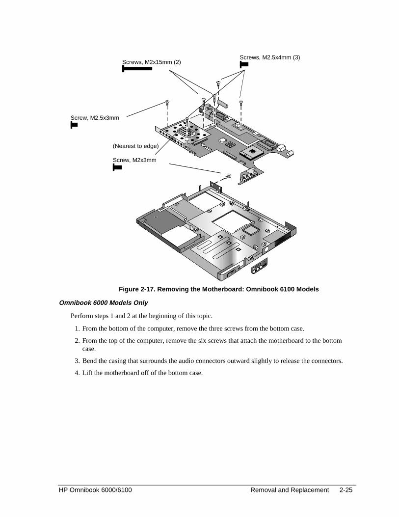
Figure 2-17. Removing the Motherboard: Omnibook 6100 Models
Omnibook 6000 Models Only
Perform steps 1 and 2 at the beginning of this topic.
1. From the bottom of the computer, remove the three screws from the bottom case.
2. From the top of the computer, remove the six screws that attach the motherboard to the bottomcase.
3. Bend the casing that surrounds the audio connectors outward slightly to release the connectors.
4. Lift the motherboard off of the bottom case.
Screws, M2x15mm (2)Screws, M2.5x4mm (3)
Screw, M2.5x3mm
Screw, M2x3mm
(Nearest to edge)

2-26 Removal and Replacement HP Omnibook 6000/6100
Figure 2-18. Removing the Motherboard: Omnibook 6000 Models
Reassembly Notes
All Models
• Omnibook 6100 models only: Replace the sound/IR panel before replacing the motherboard.
• Insert the audio connectors through their openings in the bottom case, then lower the motherboardinto place.
• When reinstalling the sound/IR panel, make sure the volume control is oriented properly (pinsfacing inward). Insert the tabs on the end of the panel into the slots in the bottom case.
• Omnibook 6000 models only: When installing the vent panel, insert the pin on the back end of thepanel under the bracket on the bottom case.
• Wireless models only: Before installing the motherboard, make sure the round coax cable fromthe front antenna PCA is held by the clips in the bottom case. Reconnect the front antenna PCAflex cable before reinstalling the top case. To reinstall the rear antenna PCA, place the PCA in itsposition near the left hinge, replace the screw, then thread the cable through to the bottom of thecomputer and reconnect the cable to mini-PCI card #1.
Screws, M2.5x6mm (3)
Screws, M2x15mm (2)
Screws, M2.5x4mm (3)
HP Omnibook 6000/6100 Removal and Replacement 2-27
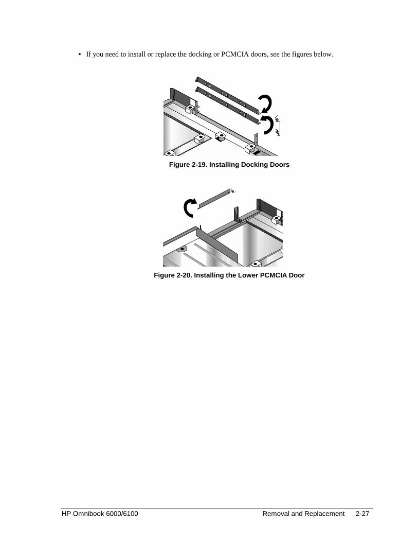
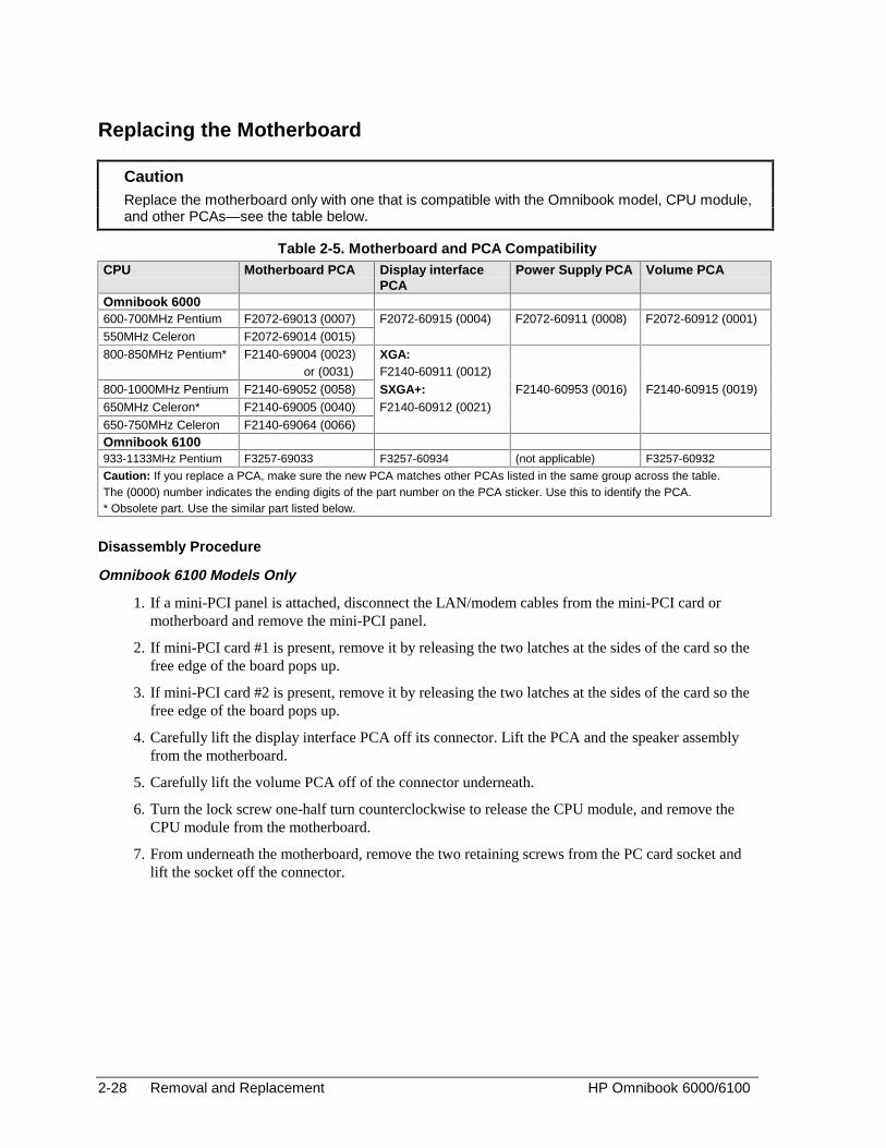
• If you need to install or replace the docking or PCMCIA doors, see the figures below.
Figure 2-19. Installing Docking Doors
Figure 2-20. Installing the Lower PCMCIA Door
2-28 Removal and Replacement HP Omnibook 6000/6100
Replacing the Motherboard
Caution Replace the motherboard only with one that is compatible with the Omnibook model, CPU module,and other PCAs—see the table below.
Table 2-5. Motherboard and PCA CompatibilityCPU Motherboard PCA Display interface
PCAPower Supply PCA Volume PCA
Omnibook 6000600-700MHz Pentium F2072-69013 (0007) F2072-60915 (0004) F2072-60911 (0008) F2072-60912 (0001)550MHz Celeron F2072-69014 (0015)800-850MHz Pentium* F2140-69004 (0023) XGA:
or (0031) F2140-60911 (0012)800-1000MHz Pentium F2140-69052 (0058) SXGA+: F2140-60953 (0016) F2140-60915 (0019)
650MHz Celeron* F2140-69005 (0040) F2140-60912 (0021)650-750MHz Celeron F2140-69064 (0066)Omnibook 6100933-1133MHz Pentium F3257-69033 F3257-60934 (not applicable) F3257-60932
Caution: If you replace a PCA, make sure the new PCA matches other PCAs listed in the same group across the table.The (0000) number indicates the ending digits of the part number on the PCA sticker. Use this to identify the PCA.* Obsolete part. Use the similar part listed below.
Disassembly Procedure
Omnibook 6100 Models Only
1. If a mini-PCI panel is attached, disconnect the LAN/modem cables from the mini-PCI card ormotherboard and remove the mini-PCI panel.
2. If mini-PCI card #1 is present, remove it by releasing the two latches at the sides of the card so thefree edge of the board pops up.
3. If mini-PCI card #2 is present, remove it by releasing the two latches at the sides of the card so thefree edge of the board pops up.
4. Carefully lift the display interface PCA off its connector. Lift the PCA and the speaker assemblyfrom the motherboard.
5. Carefully lift the volume PCA off of the connector underneath.
6. Turn the lock screw one-half turn counterclockwise to release the CPU module, and remove theCPU module from the motherboard.
7. From underneath the motherboard, remove the two retaining screws from the PC card socket andlift the socket off the connector.
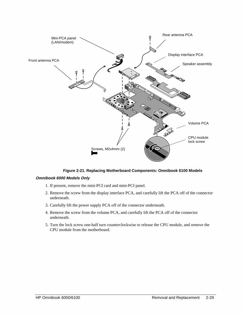
HP Omnibook 6000/6100 Removal and Replacement 2-29
Figure 2-21. Replacing Motherboard Components: Omnibook 6100 Models
Omnibook 6000 Models Only
1. If present, remove the mini-PCI card and mini-PCI panel.
2. Remove the screw from the display interface PCA, and carefully lift the PCA off of the connectorunderneath.
3. Carefully lift the power supply PCA off of the connector underneath.
4. Remove the screw from the volume PCA, and carefully lift the PCA off of the connectorunderneath.
5. Turn the lock screw one-half turn counterclockwise to release the CPU module, and remove theCPU module from the motherboard.
Volume PCA
CPU modulelock screw
Display interface PCA
Screws, M2x4mm (2)
Speaker assembly
Mini-PCA panel(LAN/modem)
Front antenna PCA
Rear antenna PCA

2-30 Removal and Replacement HP Omnibook 6000/6100
Figure 2-22. Replacing Motherboard Components: Omnibook 6000 Models
Reassembly Procedure
All Models
1. Install these components from the old motherboard on the new motherboard: display interfacePCA, speaker assembly (Omnibook 6100 models only), volume PCA, power supply PCA(Omnibook 6000 models only), CPU module, PCMCIA socket, mini-PCI card #1 (if present), andmini-PCI card #2 (if present, Omnibook 6100 models only).
Omnibook 6100: To reattach the display interface PCA to the motherboard, you must firstdisconnect the cable that attaches it to the speaker assembly, connect the PCA, then slide thespeaker assembly underneath the PCA and reconnect the cable.
2. Omnibook 6000 models only: Make sure the SpeedStep power level DIP switches on themotherboard are set correctly for the CPU. See the note on page 2-20.
3. Follow the “Reassembly Notes” in the section entitled “Removing the Motherboard or BottomCase.”
4. Store the service ID, serial number, keyboard layout, and display information electronically in thenew motherboard, and reprogram the EEPROM on the new motherboard with the proper settingsfor the display—see page 2-31. If the EEPROM is not programmed correctly, the display will notturn on.
Power supply PCA
Volume PCA
Screw, M2.5x4mm
CPU modulelock screw
Screw, M2.5x4mm
Display interface PCA
Screws, M2x4mm (2)

HP Omnibook 6000/6100 Removal and Replacement 2-31
Storing Unit Information Electronically
When replacing a motherboard PCA, you will need to download the Omnibook 6000/6100 servicepackage from the Partnership Web site (see page vi). This package contains the following:
• Image for creating a bootable Service Utilities floppy disk.
• Readme file that explains how to create and use the above floppy disks.
On Omnibook 6000 models, the service utility disk is used to update the EEPROM. If the previousmotherboard was able to boot with the service utility floppy disk, information can be stored onto thefloppy disk so that it can be transferred to the new motherboard. If this information cannot betransferred, the floppy disk can be used to update the LCD and ESN information manually.
Electronic Serial Number (ESN)
New motherboards should arrive with a default value in the EEPROM for the ESN. This default valuewill trigger the unit to ask for the ESN upon the first boot. If the wrong ESN is stored in the newmotherboard’s EEPROM (if you see the wrong ESN on the boot screen or BIOS setup), you must enterthe correct ESN manually by using the service utility disk. You will need to obtain a passcode from acall center agent to complete this process.
Service Identification Number (Service ID)
The Service ID is a number that corresponds to an encrypted date of purchase so that the warrantyperiod can be easily determined. If possible, transfer this number from the old motherboard to the newmotherboard using the service utility disk. If transfer is not possible, then no update is needed and theService ID should remain “00000” so that a new date is not generated, which could cause confusion.
LCD Settings (Omnibook 6000 models only)
LCD settings int he EEPROM must match the display DIP switch settings on the display interfacePCA. If the settings in these two locations do not match, the display will not work properly. The serviceutility disk can update the settings so they match.

2-32 Removal and Replacement HP Omnibook 6000/6100
Replacing the Bottom Case
Installation Procedure
1. Install a new Microsoft Product ID label.
2. Transfer the old serial number label and install a new overlay, or create a new serial number labelusing the steps below.
3. Follow the “Reassembly Notes” on page 2-26.
Installing a New Serial Number Label
Download the latest version of the serial number label template (Microsoft Word format) from thePartnership Web site (see page vi) under Support/Service in Technical Support Information. Store itwith other Word templates on a PC connected to a laser printer. The latest version includes fields forwarranty period and manufacturing location.
1. Open a new document based on the serial label template.
2. Enter the information from the old serial label, and print the new label on plain white paper. Thenew label does not have barcodes.
3. Carefully cut out the new serial label just inside the border and place it into the inner recess in thebottom case. The bottom of the label goes toward the front of the case.
4. Ensure that all regulatory labels that appeared on the old bottom case are present on the newbottom case. This may be accomplished by keeping the old covers, if necessary.
5. While holding the paper label in place, attach a serial label overlay into the outer recess. It coversand protects the serial label.
HP Serial Number (S)TW711A1234 1YR
(1P) F2072 W EA MFG# TW711A1234
Made in Taiwan
Figure 2-23. Example of Serial Number Label
HP Omnibook 6000/6100 Removal and Replacement 2-33
Repairing the BIOS IC(HP Authorized Service Providers Only)
The BIOS IC of the computer is not replaceable:
• If the BIOS IC is defective, you must replace the power supply PCA on Omnibook 6000 models orthe motherboard on Omnibook 6100 models.
• However, if the BIOS IC might only be corrupted, you can attempt to repair it using a CrisisRecovery floppy—see the information below.
Note: Reprogramming the BIOS IC
A new BIOS IC contains only enough basic programming to boot the Omnibook. After installing anew power supply PCA, you must reprogram the BIOS IC, preferably with the latest BIOS. You candownload the latest BIOS from the HP Notebook Web site (see page vi)—follow the directionsprovided.
If you do not have a BIOS Crisis Recovery floppy, download the package from the Partnership Website (see page vi) under Product Support Information in the Service and Support Library. Follow theinstructions for creating the floppy.
Caution Make sure you are using the correct BIOS Crisis Recovery floppy for the Omnibook model you arerepairing. The program does not verify the Omnibook model, so you could install the wrong BIOSimage.
1. Insert the BIOS Crisis Recovery floppy in the floppy drive.
2. If the computer does not boot from the BIOS Crisis Recovery floppy, try plugging the boot-blockjumper into the Omnibook parallel port, then go to the next step. See the wiring diagram below.
(In many situations you can skip this step—especially if the computer previously displayed a BIOSchecksum error.)
3. Turn on the computer and allow it to boot from the floppy disk.
If the computer does not turn on at all, do the following steps to boot from the floppy disk:
• Unplug the AC adapter.
• Press and hold Fn+B.
• Plug in the AC adapter.
• Release Fn+B.
4. Wait while the BIOS is reprogrammed—the display is blank for a minute or more while thishappens.
If you plugged in a boot block jumper, unplug it before the computer automatically reboots.
5. After the BIOS is repaired and reprogrammed, check the BIOS version to see whether it is thelatest version. If necessary, reprogram the BIOS IC—see the note at the beginning of this topic.

2-34 Removal and Replacement HP Omnibook 6000/6100
14
1
25
13
Figure 2-24. Boot-Block Jumper
Removing Other Components(HP Authorized Service Providers Only)
Required Equipment
• Small Phillips screwdriver.
• Small flat-blade screwdriver.
Removal Procedure
1. Unplug the AC adapter, if present, and remove the battery. Remove the secondary battery if one isinstalled.
2. Remove the assemblies and follow the additional steps given in the table below.
Table 2-6. Removing Omnibook Components
Component Removal Procedure Additional Steps
Battery, CMOS Power button panel(page 2-11).Keyboard (page 2-15).Heatsink (page 2-17).
Reassembly Notes: After replacing the CMOSbattery, set the correct time and date using the BIOSSetup utility or Date/Time in the Control Panel.
Card, mini-PCI #2(Omnibook 6100 only)
Plug-in module (page 2-5).Hard disk drive (page 2-7).Power button panel(page 2-11).Keyboard (page 2-15).Heatsink (page 2-17).Display assembly(page 2-13).Top case (page 2-20).Motherboard (page 2-24).
The card is attached to bottom side of themotherboard. Release the two latches at the sides ofthe card so the free edge of the board pops up.
Case, bottom See page 2-22.
Case, top See page 2-20.
Covers, hinge (left,right, or center)
Power button panel(page 2-11).Display assembly(page 2-13).
Caution: When removing the center hinge cover, becareful not to pull on or damage the display cable.Reassembly Notes: Make sure the center hinge coverfits over the tab in the bottom case.
CPU module See page 2-19.
Display assembly See page 2-13.
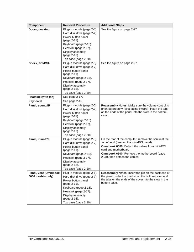
HP Omnibook 6000/6100 Removal and Replacement 2-35
Component Removal Procedure Additional Steps
Doors, docking Plug-in module (page 2-5).Hard disk drive (page 2-7).Power button panel(page 2-11).Keyboard (page 2-15).Heatsink (page 2-17).Display assembly(page 2-13).Top case (page 2-20).
See the figure on page 2-27.
Doors, PCMCIA Plug-in module (page 2-5).Hard disk drive (page 2-7).Power button panel(page 2-11).Keyboard (page 2-15).Heatsink (page 2-17).Display assembly(page 2-13).Top case (page 2-20).
See the figure on page 2-27.
Heatsink (with fan) See page 2-17.
Keyboard See page 2-15.
Panel, sound/IR Plug-in module (page 2-5).Hard disk drive (page 2-7).Power button panel(page 2-11).Keyboard (page 2-15).Heatsink (page 2-17).Display assembly(page 2-13).Top case (page 2-20).
Reassembly Notes: Make sure the volume control isoriented properly (pins facing inward). Insert the tabson the ends of the panel into the slots in the bottomcase.
Panel, mini-PCI Plug-in module (page 2-5).Hard disk drive (page 2-7).Power button panel(page 2-11).Keyboard (page 2-15).Heatsink (page 2-17).Display assembly(page 2-13).Top case (page 2-20).
On the rear of the computer, remove the screw at thefar left end (nearest the mini-PCI panel).Omnibook 6000: Detach the cables from mini-PCIcard and motherboard.Omnibook 6100: Remove the motherboard (page2-28), then detach the cables.
Panel, vent (Omnibook6000 models only)
Plug-in module (page 2-5).Hard disk drive (page 2-7).Power button panel(page 2-11).Keyboard (page 2-15).Heatsink (page 2-17).Display assembly(page 2-13).Top case (page 2-20).
Reassembly Notes: Insert the pin on the back end ofthe panel under the bracket on the bottom case, andthe tabs on the ends of the cover into the slots in thebottom case.
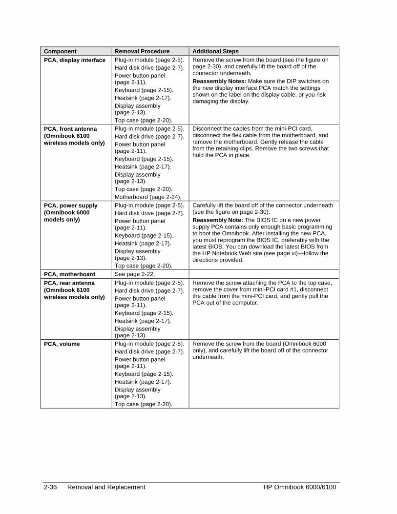
2-36 Removal and Replacement HP Omnibook 6000/6100
Component Removal Procedure Additional Steps
PCA, display interface Plug-in module (page 2-5).Hard disk drive (page 2-7).Power button panel(page 2-11).Keyboard (page 2-15).Heatsink (page 2-17).Display assembly(page 2-13).Top case (page 2-20).
Remove the screw from the board (see the figure onpage 2-30), and carefully lift the board off of theconnector underneath.Reassembly Notes: Make sure the DIP switches onthe new display interface PCA match the settingsshown on the label on the display cable, or you riskdamaging the display.
PCA, front antenna(Omnibook 6100wireless models only)
Plug-in module (page 2-5).Hard disk drive (page 2-7).Power button panel(page 2-11).Keyboard (page 2-15).Heatsink (page 2-17).Display assembly(page 2-13).Top case (page 2-20).Motherboard (page 2-24).
Disconnect the cables from the mini-PCI card,disconnect the flex cable from the motherboard, andremove the motherboard. Gently release the cablefrom the retaining clips. Remove the two screws thathold the PCA in place.
PCA, power supply(Omnibook 6000models only)
Plug-in module (page 2-5).Hard disk drive (page 2-7).Power button panel(page 2-11).Keyboard (page 2-15).Heatsink (page 2-17).Display assembly(page 2-13).Top case (page 2-20).
Carefully lift the board off of the connector underneath(see the figure on page 2-30).Reassembly Note: The BIOS IC on a new powersupply PCA contains only enough basic programmingto boot the Omnibook. After installing the new PCA,you must reprogram the BIOS IC, preferably with thelatest BIOS. You can download the latest BIOS fromthe HP Notebook Web site (see page vi)—follow thedirections provided.
PCA, motherboard See page 2-22.
PCA, rear antenna(Omnibook 6100wireless models only)
Plug-in module (page 2-5).Hard disk drive (page 2-7).Power button panel(page 2-11).Keyboard (page 2-15).Heatsink (page 2-17).Display assembly(page 2-13).
Remove the screw attaching the PCA to the top case,remove the cover from mini-PCI card #1, disconnectthe cable from the mini-PCI card, and gently pull thePCA out of the computer.
PCA, volume Plug-in module (page 2-5).Hard disk drive (page 2-7).Power button panel(page 2-11).Keyboard (page 2-15).Heatsink (page 2-17).Display assembly(page 2-13).Top case (page 2-20).
Remove the screw from the board (Omnibook 6000only), and carefully lift the board off of the connectorunderneath.
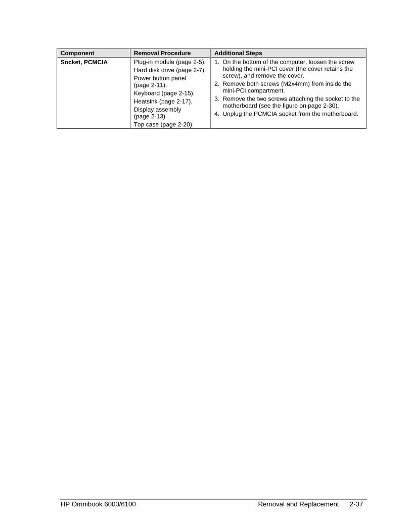
HP Omnibook 6000/6100 Removal and Replacement 2-37
Component Removal Procedure Additional Steps
Socket, PCMCIA Plug-in module (page 2-5).Hard disk drive (page 2-7).Power button panel(page 2-11).Keyboard (page 2-15).Heatsink (page 2-17).Display assembly(page 2-13).Top case (page 2-20).
1. On the bottom of the computer, loosen the screwholding the mini-PCI cover (the cover retains thescrew), and remove the cover.
2. Remove both screws (M2x4mm) from inside themini-PCI compartment.
3. Remove the two screws attaching the socket to themotherboard (see the figure on page 2-30).
4. Unplug the PCMCIA socket from the motherboard.


HP Omnibook 6000/6100 Troubleshooting and Diagnostics 3-1
3
Troubleshooting and Diagnostics
This chapter includes troubleshooting and diagnostic information for testing the functionality of theOmnibook and identifying faulty modules:
• Troubleshooting information
� Troubleshooting the problem (page 3-3).
� Verifying the repair (page 3-4).
� Suggestions for troubleshooting (page 3-5).
• Diagnostic tools
� Omnibook e-Diagtools diagnostic program (older models include Diagtools) (page 3-17).
� Power-on self-test (page 3-24).
� Sycard PCCtest 450 PC Card (page 3-27).
� Desktop Management Interface (page 3-28).
� BIOS Setup utility (page 3-29).

3-2 Troubleshooting and Diagnostics HP Omnibook 6000/6100
Troubleshooting
The suggestions in this section can help isolate and repair the cause of a problem. To ensure qualityrepair, HP recommends that you follow the basic troubleshooting steps shown in the illustrationbelow.
Check the customer’s descriptionof the problem and any supportinginformation.
Try to duplicate the customer’sproblem.
Troubleshoot the problem using: - Diagnostic tools. - Troubleshooting suggestions.
Verify the repair by testing thefunctionality of the complete unit.
Check for customer abuse.
Figure 3-1. Basic Troubleshooting Steps

HP Omnibook 6000/6100 Troubleshooting and Diagnostics 3-3
Checking for Customer Abuse
Some units may appear to have been damaged by customer abuse. Use these guidelines to helpdetermine if this is the case:
• If the shipping box is seriously damaged, customer abuse cannot be declared.
• If the damage could have a cause other than customer abuse, customer abuse cannot be declared.
• If the unit shows any of the following, customer abuse is declared:
� Missing parts.
� Broken plastic parts.
� Parts not original to the unit.
� Damaged or missing keys on the keyboard.
Table 3-2 includes additional criteria for determining customer abuse to specific parts of the unit.
Important
Parts damaged by customer abuse are not covered by the warranty.
Troubleshooting the Problem
Record pertinent information about the unit:
• Model and serial number.
• Operating system and version.
• BIOS version.
• Accessories and peripherals used.
Analyze the problem:
• Observe Symptoms. Using the customer’s information, try to duplicate the problem. Determinehow the problem differs from proper behavior. Also, take note of the functions that do workproperly.
• Separate Problems. If there is more than one symptom, separate them into distinct problems.
• Consider Causes. Keep in mind possible causes for each problem. Use the diagnostic tools andtroubleshooting suggestions to help find possible causes.
� The e-Diagtools diagnostic program tests most components of the Omnibook’s componentsusing automatic and interactive tests, and will be your primary troubleshooting tool. Othertools include the power-on self-test, DMI/Toptools (if installed), the BIOS Setup utility, andthe Sycard PCCtest. The table on page 3-5 shows how you can use these tools to isolate thecause of the computer’s problem.
� The troubleshooting suggestions on page 3-6 include general suggestions for repairing unitswith specific failure symptoms.

3-4 Troubleshooting and Diagnostics HP Omnibook 6000/6100
Swapping modules that may be defective with others known to be good is generally an ideal way tofind the module responsible for the problem. A failure symptom is rarely caused by more than onemodule, so you will not usually need to replace more than one module to correct a particular failure.
After you replace a module, the computer will normally be in a confused state and lock up when youapply power. If this happens, press the system-off switch: this resets the computer and starts it in aknown state.
Verifying the Repair
Before returning the repaired unit to the customer, verify the repair by running the following tests:
• Basic Diagnostic Test. Run the basic test of the e-Diagtools diagnostic program (page 3-17).
–and–
• Function Tests. Run tests that check the repaired function, such as in the e-Diagtools diagnosticprogram (page 3-17).
–and–
• Failed Tests. Run any other tests that failed during troubleshooting.
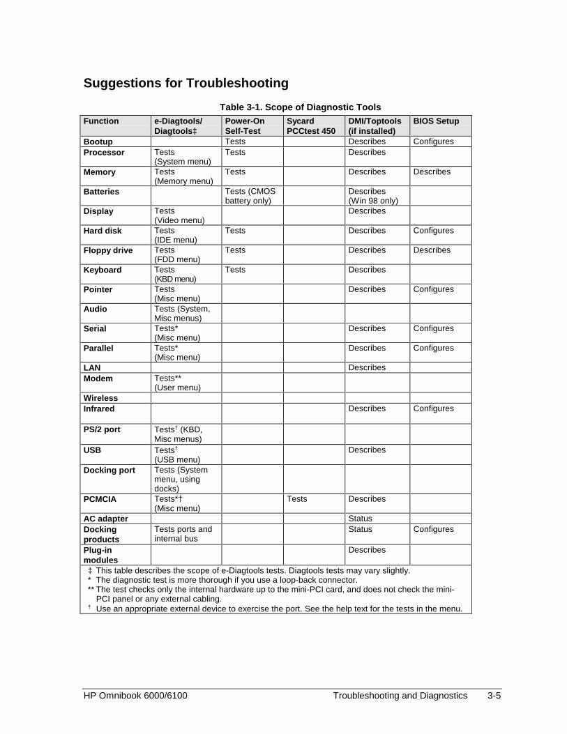
HP Omnibook 6000/6100 Troubleshooting and Diagnostics 3-5
Suggestions for Troubleshooting
Table 3-1. Scope of Diagnostic ToolsFunction e-Diagtools/
Diagtools‡Power-OnSelf-Test
SycardPCCtest 450
DMI/Toptools(if installed)
BIOS Setup
Bootup Tests Describes ConfiguresProcessor Tests
(System menu)Tests Describes
Memory Tests(Memory menu)
Tests Describes Describes
Batteries Tests (CMOSbattery only)
Describes(Win 98 only)
Display Tests(Video menu)
Describes
Hard disk Tests(IDE menu)
Tests Describes Configures
Floppy drive Tests(FDD menu)
Tests Describes Describes
Keyboard Tests(KBD menu)
Tests Describes
Pointer Tests(Misc menu)
Describes Configures
Audio Tests (System,Misc menus)
Serial Tests*(Misc menu)
Describes Configures
Parallel Tests*(Misc menu)
Describes Configures
LAN DescribesModem Tests**
(User menu)WirelessInfrared Describes Configures
PS/2 port Tests† (KBD,Misc menus)
USB Tests†
(USB menu)Describes
Docking port Tests (Systemmenu, usingdocks)
PCMCIA Tests*†(Misc menu)
Tests Describes
AC adapter StatusDockingproducts
Tests ports andinternal bus
Status Configures
Plug-inmodules
Describes
‡ This table describes the scope of e-Diagtools tests. Diagtools tests may vary slightly.* The diagnostic test is more thorough if you use a loop-back connector.** The test checks only the internal hardware up to the mini-PCI card, and does not check the mini-
PCI panel or any external cabling.† Use an appropriate external device to exercise the port. See the help text for the tests in the menu.

3-6 Troubleshooting and Diagnostics HP Omnibook 6000/6100
If you cannot isolate the cause of a problem using the above diagnostic tools, use the suggestions inthe following table to help find the problem.
Table 3-2. Troubleshooting Suggestions
Symptom Call Center:Suggestions
Repair Center:Likely Causes
Repair Center:Comments
To help determine likely causes, check to see what replaceable modules are involved in the system function andwhat roles they play. See the figure on page 1-14 and the table on page 1-15.
StartupDoes not boot onAC or battery.
Check the power source.Press the system-off switchto reset the computer. Pressthe blue sleep button to turnthe computer on.Unplug the AC adapter andremove all batteries, thenreconnect power.Remove all but one SDRAMmodules and try again.Reinsert any other SDRAMmodules and try again.
AC adapter.SDRAM module.CPU module.Power supply PCA.Display interface
PCA.Motherboard.Display assembly.Hard drive.
Check AC adapter. Removeany SDRAM modules andretry.If power status light does notturn on, reprogram BIOS,replace power supply PCA,replace motherboard.If power status light turns onbut display remains off, tryexternal monitor. If monitorshows successful boot,replace display assembly. Ifmonitor shows activity butBIOS does not complete,replace display assembly. Ifmonitor is blank, replacedisplay interface PCA,replace display interface,replace motherboard.If power status light anddisplay turn on, BIOScompletes, but OS does notstart from hard disk or fromfloppy drive, replace CPUmodule, then motherboard. IfOS starts from floppy drive,reload hard drive, replacehard drive.
Beeps once, spinshard disk, repeats,but does not boot.
SDRAM module. Make sure at least oneSDRAM module is installed.
Does not boot onbattery, but bootson ac.
Check battery level onbattery LEDs.Check battery contacts. Ifavailable, try another battery.
Battery or contacts.Motherboard.
Does not boot fromfloppy drive.
Make sure the floppy disk isbootable.Make sure the floppy drive isinstalled or connectedcorrectly.Use BIOS Setup to check theboot order and to make surethat floppy boot is enabled.Try using alternateconnection (with or withoutfloppy cable).
Floppy drive orcontacts.
Floppy cable.Motherboard.
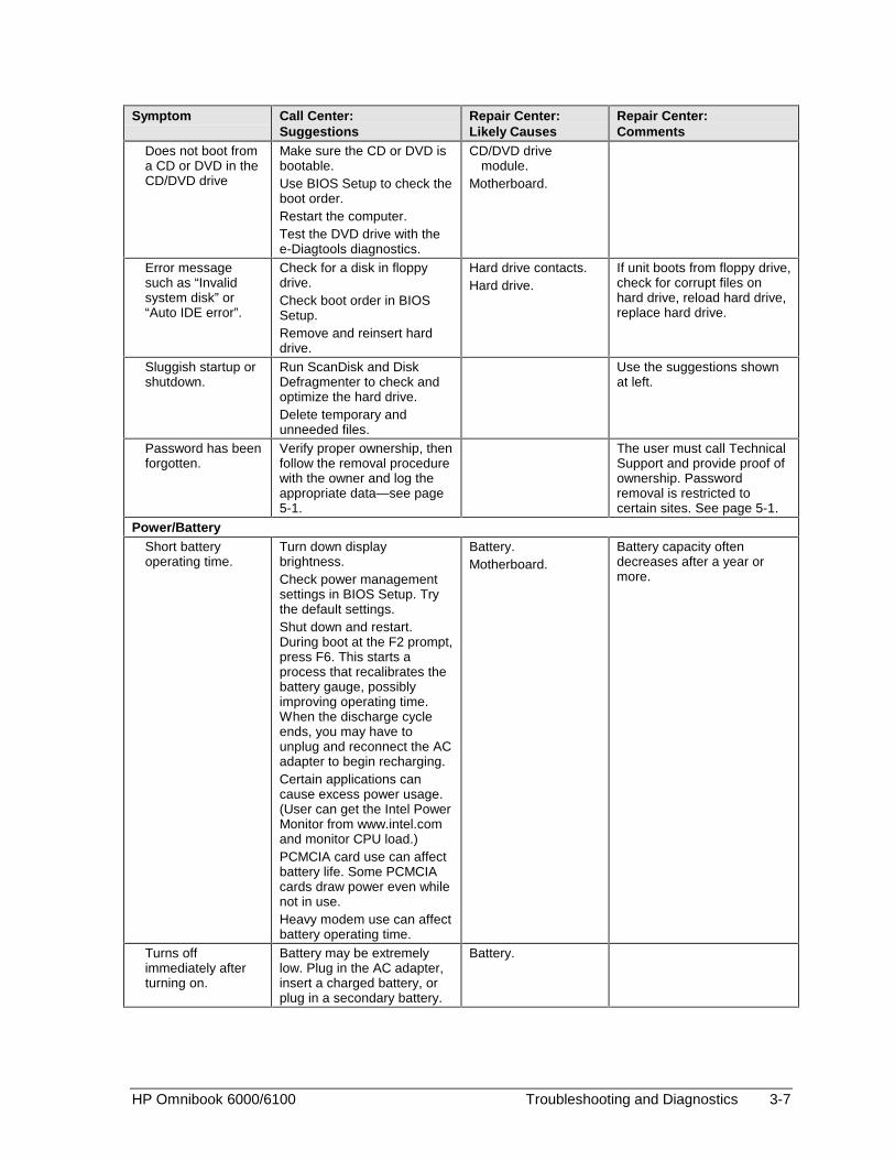
HP Omnibook 6000/6100 Troubleshooting and Diagnostics 3-7
Symptom Call Center:Suggestions
Repair Center:Likely Causes
Repair Center:Comments
Does not boot froma CD or DVD in theCD/DVD drive
Make sure the CD or DVD isbootable.Use BIOS Setup to check theboot order.Restart the computer.Test the DVD drive with thee-Diagtools diagnostics.
CD/DVD drivemodule.
Motherboard.
Error messagesuch as “Invalidsystem disk” or“Auto IDE error”.
Check for a disk in floppydrive.Check boot order in BIOSSetup.Remove and reinsert harddrive.
Hard drive contacts.Hard drive.
If unit boots from floppy drive,check for corrupt files onhard drive, reload hard drive,replace hard drive.
Sluggish startup orshutdown.
Run ScanDisk and DiskDefragmenter to check andoptimize the hard drive.Delete temporary andunneeded files.
Use the suggestions shownat left.
Password has beenforgotten.
Verify proper ownership, thenfollow the removal procedurewith the owner and log theappropriate data—see page5-1.
The user must call TechnicalSupport and provide proof ofownership. Passwordremoval is restricted tocertain sites. See page 5-1.
Power/BatteryShort batteryoperating time.
Turn down displaybrightness.Check power managementsettings in BIOS Setup. Trythe default settings.Shut down and restart.During boot at the F2 prompt,press F6. This starts aprocess that recalibrates thebattery gauge, possiblyimproving operating time.When the discharge cycleends, you may have tounplug and reconnect the ACadapter to begin recharging.Certain applications cancause excess power usage.(User can get the Intel PowerMonitor from www.intel.comand monitor CPU load.)PCMCIA card use can affectbattery life. Some PCMCIAcards draw power even whilenot in use.Heavy modem use can affectbattery operating time.
Battery.Motherboard.
Battery capacity oftendecreases after a year ormore.
Turns offimmediately afterturning on.
Battery may be extremelylow. Plug in the AC adapter,insert a charged battery, orplug in a secondary battery.
Battery.

3-8 Troubleshooting and Diagnostics HP Omnibook 6000/6100
Symptom Call Center:Suggestions
Repair Center:Likely Causes
Repair Center:Comments
Does not run onbattery; emptybattery indication.
Check the battery andcontacts. If one is available,try another battery.
Battery or contacts.Motherboard.
Battery does notcharge.
Check the power source.Check the battery contacts. Ifavailable, try another batteryand AC adapter.Move the computer awayfrom any nearby heat source.Unplug the AC adapter andallow the battery to cooldown. Check for blocked airvents.
Battery or contacts.AC adapter.Motherboard.Heatsink.
Check battery and ACadapter.Check heatsink.
Secondary batterydoes not charge.
Check the power source.Make sure main battery isfully charged. If not,secondary battery will notcharge.Check contacts on secondbattery.
Second battery orcontacts.
Motherboard.
Battery indicator isinaccurate.
The Time Remaining is anestimate based on howquickly the computer is usingpower at the moment. Ittherefore depends on thecurrent task, and assumesthat power will be used at thesame rate until the batteryruns out. So, for example, ifthe computer is performing atask requiring a good deal ofpower (such as reading froma CD or DVD), the value willprobably show too little timeremaining.
DisplayDark display, nolight.
Adjust display brightness.Press Fn+F5 several times.Try external monitor.
Display cableconnection.
Display assembly.Motherboard.
Set DIP switch on displayinterface PCA to match labelon display cable. ReprogramEEPROM for display type—see page 2-31.Check the cable connection.Replace the displayassembly.If an external monitordisplays no image, replacethe motherboard.
White display. Adjust display brightness. Display assembly.Display interface
PCA.Erratic display. Display cable
connection.Display assembly.
Bright or missingpixels or lines.
See quality statement onpage 5-2.
Display cableconnection.
Display assembly.
See quality statement onpage 5-2.

HP Omnibook 6000/6100 Troubleshooting and Diagnostics 3-9
Symptom Call Center:Suggestions
Repair Center:Likely Causes
Repair Center:Comments
Punctured display. Declared to be caused bycustomer abuse.
Vertical crack nearcenter of display.
Usually caused byclosing display withpencil-sized object onkeyboard.
Declared to be caused bycustomer abuse.
Scratched displayglass.
Declared to be caused bycustomer abuse.
Local area of darkor light discolorationvisible when displayis on.
Caused by excessivepressure applied to anarea on the screen.
Declared to be caused bycustomer abuse.
Hard diskHard disk neverspins.
Check the power source.Remove and reinsert thehard drive. Check theconnector.
Hard drive orconnector.
Motherboard.
If the drive case is damaged,the drive may not operateproperly.
Hard disk makesclunking orscratching noise.
Back up the driveimmediately.Was the computer or drivedropped?
Hard drive. Check the computer anddrive for evidence ofcustomer abuse.
Hard disk makesbuzzing or whiningnoise.
Back up the driveimmediately.Check for alternate noisesources, such as a PCMCIAdrive or fan.If a keystroke causes thesound to change, it may befrom the power supply PCA.
Depends on thesource of the noise.
Files are corrupted. Run the VirusScan program.Check the disk surface byrunning Scandisk (Windows95/98) or by using the Toolstab in the disk’s Propertiessheet (Windows 2000).Test the hard disk drive withthe e-Diagtools diagnostics.Use the Recovery CD torestore original factorysoftware.
Use the suggestions shownat left.
Drive capacity isless than normal.
Check the disk surface byrunning Scandisk (Windows95/98) or by using the Toolstab in the disk’s Propertiessheet (Windows 2000).Check partitions using FDISK(Windows 95/98) or ControlPanel, Administrative Tools,Computer Managementunder Storage (Windows2000).
Hard drive. Use the suggestions shownat left.Recreate the Hibernatepartition, then partition andformat the disk.

3-10 Troubleshooting and Diagnostics HP Omnibook 6000/6100
Symptom Call Center:Suggestions
Repair Center:Likely Causes
Repair Center:Comments
Floppy driveGeneral problems. Make sure floppy drive
module is installed orconnected correctly.Try using alternateconnection (with or withoutfloppy cable).Check settings in BIOSSetup.
Floppy drive moduleor contacts.
External floppy drivecable.
Motherboard.
Floppy drive doesnot work as 3-modedrive.
3-mode drive is notsupported when the drive isconnected to a dock.
External floppy drivecable.
Floppy drive module.
KeyboardSome or all keys donot work properly.
Check settings in BIOSSetup.
Keyboard.Power supply PCA.Motherboard.
Try reinserting the flex cablein the connector on thepower supply PCA.
PS/2 keyboard andmouse with Y-adapter do notwork.
Check devices separately. Y-adapter.PS/2 device.Motherboard.
Pointing stickGeneral problems. Slide and hold the power
button four seconds to resetthe computer.Check settings in ControlPanel. Make sure pointingstick is enabled in MouseProperties.Make sure the pointing stickis enabled in BIOS Setup.
Keyboard.Power supply PCA.Motherboard.
Try reinserting the flex cablein the connector on thepower supply PCA ormotherboard.
Special pointingstick features notworking.
In Mouse Properties, selectthe Synaptics PS/2TouchPad driver. (The driveris installed from the directory\hp\Drivers\Touchpad.)
Keyboard assembly.Power supply PCA.Motherboard.
Touch padGeneral problems. Slide and hold the power
button four seconds to resetthe computer.Check settings in ControlPanel. Make sure touch padis enabled in MouseProperties.Make sure the touch pad isenabled in BIOS Setup.Check pointing stick settingsin Control Panel.
Top case.Power supply PCA.Motherboard.
Special touch padfeatures notworking.
In Mouse Properties, selectthe Synaptics PS/2TouchPad driver. (The driveris installed from the directory\hp\Drivers\Touchpad.)
Top case.Motherboard.
Click button doesnot work.
Top case.Motherboard.
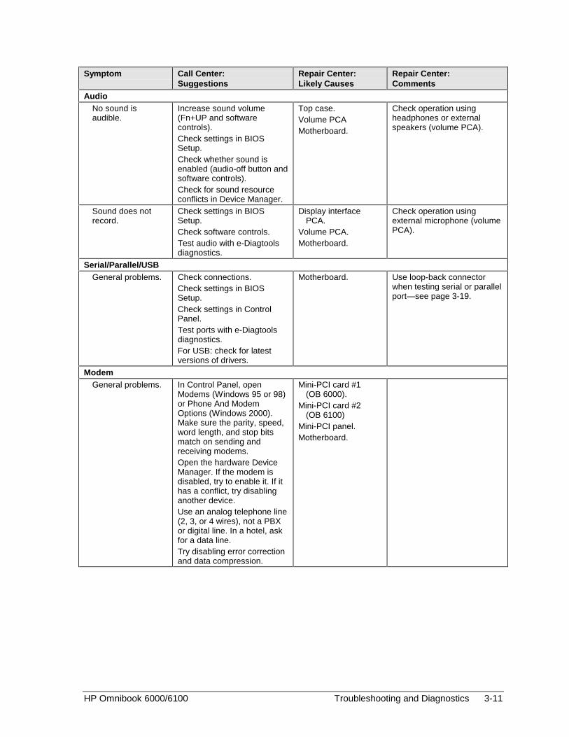
HP Omnibook 6000/6100 Troubleshooting and Diagnostics 3-11
Symptom Call Center:Suggestions
Repair Center:Likely Causes
Repair Center:Comments
AudioNo sound isaudible.
Increase sound volume(Fn+UP and softwarecontrols).Check settings in BIOSSetup.Check whether sound isenabled (audio-off button andsoftware controls).Check for sound resourceconflicts in Device Manager.
Top case.Volume PCAMotherboard.
Check operation usingheadphones or externalspeakers (volume PCA).
Sound does notrecord.
Check settings in BIOSSetup.Check software controls.Test audio with e-Diagtoolsdiagnostics.
Display interfacePCA.
Volume PCA.Motherboard.
Check operation usingexternal microphone (volumePCA).
Serial/Parallel/USBGeneral problems. Check connections.
Check settings in BIOSSetup.Check settings in ControlPanel.Test ports with e-Diagtoolsdiagnostics.For USB: check for latestversions of drivers.
Motherboard. Use loop-back connectorwhen testing serial or parallelport—see page 3-19.
ModemGeneral problems. In Control Panel, open
Modems (Windows 95 or 98)or Phone And ModemOptions (Windows 2000).Make sure the parity, speed,word length, and stop bitsmatch on sending andreceiving modems.Open the hardware DeviceManager. If the modem isdisabled, try to enable it. If ithas a conflict, try disablinganother device.Use an analog telephone line(2, 3, or 4 wires), not a PBXor digital line. In a hotel, askfor a data line.Try disabling error correctionand data compression.
Mini-PCI card #1(OB 6000).
Mini-PCI card #2(OB 6100)
Mini-PCI panel.Motherboard.
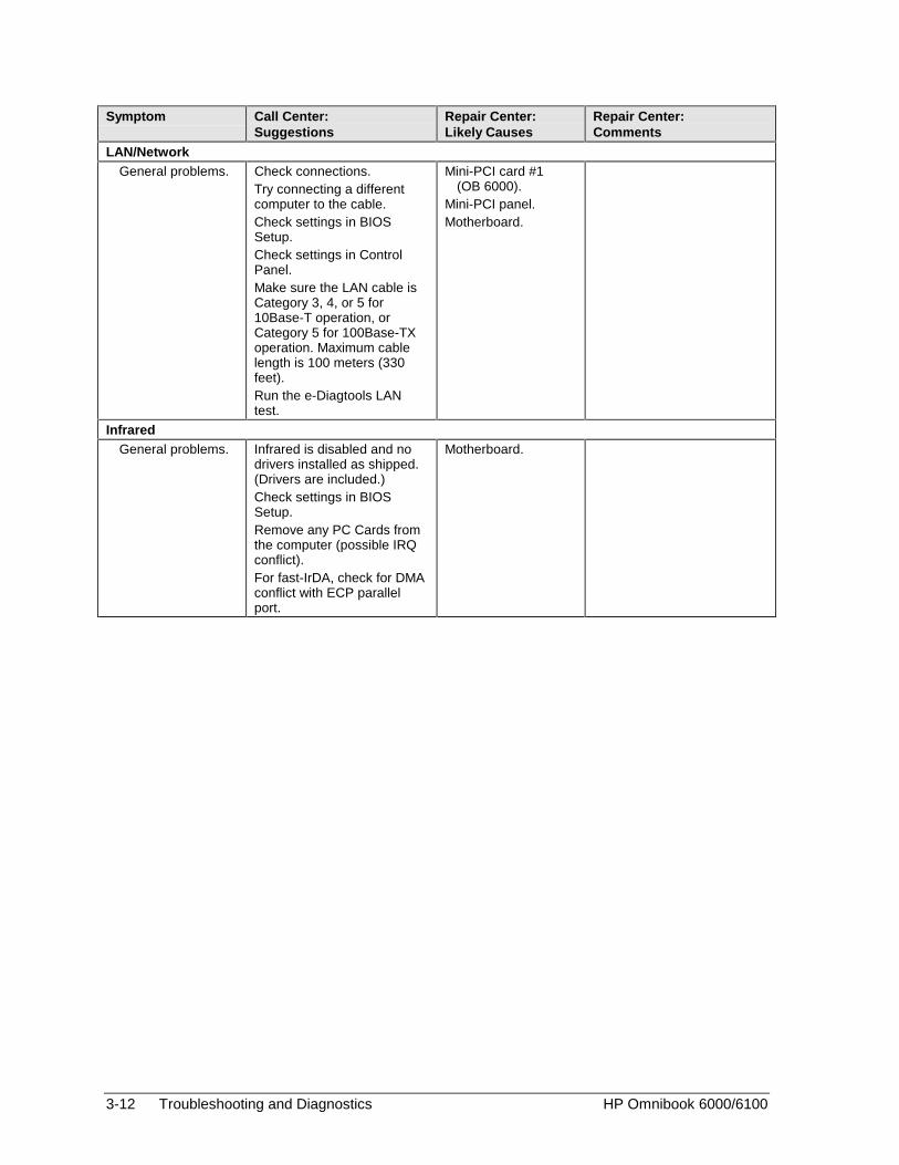
3-12 Troubleshooting and Diagnostics HP Omnibook 6000/6100
Symptom Call Center:Suggestions
Repair Center:Likely Causes
Repair Center:Comments
LAN/NetworkGeneral problems. Check connections.
Try connecting a differentcomputer to the cable.Check settings in BIOSSetup.Check settings in ControlPanel.Make sure the LAN cable isCategory 3, 4, or 5 for10Base-T operation, orCategory 5 for 100Base-TXoperation. Maximum cablelength is 100 meters (330feet).Run the e-Diagtools LANtest.
Mini-PCI card #1(OB 6000).
Mini-PCI panel.Motherboard.
InfraredGeneral problems. Infrared is disabled and no
drivers installed as shipped.(Drivers are included.)Check settings in BIOSSetup.Remove any PC Cards fromthe computer (possible IRQconflict).For fast-IrDA, check for DMAconflict with ECP parallelport.
Motherboard.
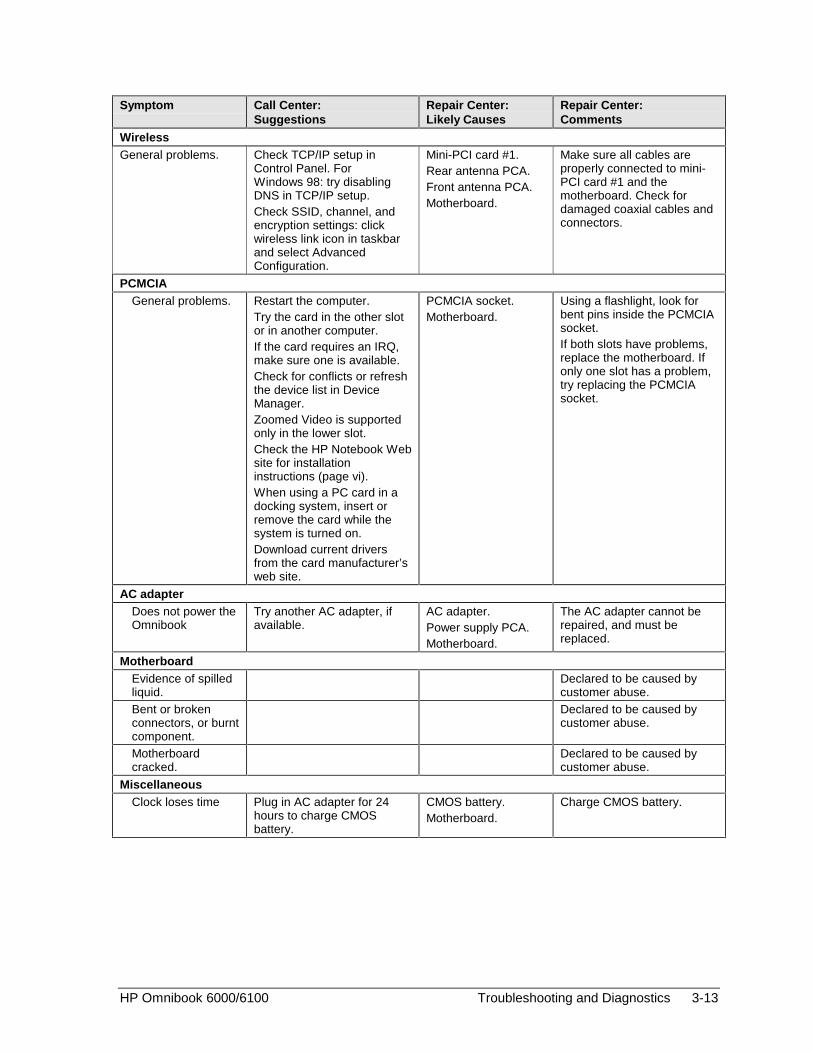
HP Omnibook 6000/6100 Troubleshooting and Diagnostics 3-13
Symptom Call Center:Suggestions
Repair Center:Likely Causes
Repair Center:Comments
WirelessGeneral problems. Check TCP/IP setup in
Control Panel. ForWindows 98: try disablingDNS in TCP/IP setup.Check SSID, channel, andencryption settings: clickwireless link icon in taskbarand select AdvancedConfiguration.
Mini-PCI card #1.Rear antenna PCA.Front antenna PCA.Motherboard.
Make sure all cables areproperly connected to mini-PCI card #1 and themotherboard. Check fordamaged coaxial cables andconnectors.
PCMCIAGeneral problems. Restart the computer.
Try the card in the other slotor in another computer.If the card requires an IRQ,make sure one is available.Check for conflicts or refreshthe device list in DeviceManager.Zoomed Video is supportedonly in the lower slot.Check the HP Notebook Website for installationinstructions (page vi).When using a PC card in adocking system, insert orremove the card while thesystem is turned on.Download current driversfrom the card manufacturer’sweb site.
PCMCIA socket.Motherboard.
Using a flashlight, look forbent pins inside the PCMCIAsocket.If both slots have problems,replace the motherboard. Ifonly one slot has a problem,try replacing the PCMCIAsocket.
AC adapterDoes not power theOmnibook
Try another AC adapter, ifavailable.
AC adapter.Power supply PCA.Motherboard.
The AC adapter cannot berepaired, and must bereplaced.
MotherboardEvidence of spilledliquid.
Declared to be caused bycustomer abuse.
Bent or brokenconnectors, or burntcomponent.
Declared to be caused bycustomer abuse.
Motherboardcracked.
Declared to be caused bycustomer abuse.
MiscellaneousClock loses time Plug in AC adapter for 24
hours to charge CMOSbattery.
CMOS battery.Motherboard.
Charge CMOS battery.
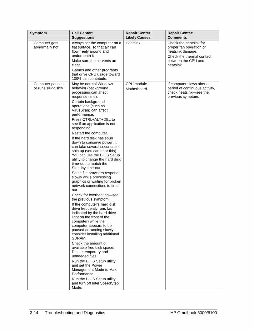
3-14 Troubleshooting and Diagnostics HP Omnibook 6000/6100
Symptom Call Center:Suggestions
Repair Center:Likely Causes
Repair Center:Comments
Computer getsabnormally hot
Always set the computer on aflat surface, so that air canflow freely around andunderneath itMake sure the air vents areclear.Games and other programsthat drive CPU usage toward100% can contribute.
Heatsink. Check the heatsink forproper fan operation orheatsink damage.Check the thermal contactbetween the CPU andheatsink.
Computer pausesor runs sluggishly
May be normal Windowsbehavior (backgroundprocessing can affectresponse time).Certain backgroundoperations (such asVirusScan) can affectperformance.Press CTRL+ALT+DEL tosee if an application is notresponding.Restart the computer.If the hard disk has spundown to conserve power, itcan take several seconds tospin up (you can hear this).You can use the BIOS Setuputility to change the hard disktime-out to match theStandby time-out.Some file browsers respondslowly while processinggraphics or waiting for brokennetwork connections to timeout.Check for overheating—seethe previous symptom.If the computer’s hard diskdrive frequently runs (asindicated by the hard drivelight on the front of thecomputer) while thecomputer appears to bepaused or running slowly,consider installing additionalSDRAM.Check the amount ofavailable free disk space.Delete temporary andunneeded files.Run the BIOS Setup utilityand set the PowerManagement Mode to Max.Performance.Run the BIOS Setup utilityand turn off Intel SpeedStepMode.
CPU module.Motherboard.
If computer slows after aperiod of continuous activity,check heatsink—see theprevious symptom.

HP Omnibook 6000/6100 Troubleshooting and Diagnostics 3-15
Symptom Call Center:Suggestions
Repair Center:Likely Causes
Repair Center:Comments
Computer is still onbut stopsresponding.
Press CTRL+ALT+DEL andend any application that isnot responding.Slide and hold the powerbutton four seconds to turnoff and reset the computer.Press the blue sleep buttonto turn the computer back on.If the above fails, insert astraightened paper clip intothe system-off switch. Thenpress the blue sleep buttonto turn the computer back on.
Does not suspendto Standby mode asexpected.
The computer won’t suspendif it has an active connectionto another computer.If the computer is busy, itnormally waits to finish thecurrent operation beforesuspending.
Does notautomatically enterHibernate mode asexpected.
For Windows 2000, makesure hibernate support isenabled in Power in ControlPanel. Also, make sure theHibernate timeouts (PowerSchemes tab) for AC andbattery power are not set toNever.For Windows 98, check theHibernate timeout in BIOSSetup. If the computer hasmore than 512 MB (OB 6000)or 768 MB (OB 6100) ofSDRAM, the Utility partitionon the hard disk must beexpanded.
Standby optionmissing from ShutDown window.
Do not allow Windows 98 todisable APM. If it promptsyou to do so, answer No.In System in Control Panel,expand System Devices(System Manager tab), andremove Advanced PowerManagement. Restart thecomputer, then use Add NewHardware in Control Panel toinstall support for APM.Restart the computer.
Plug-in ModulesGeneral problems. Make sure module is
installed properly.Reset computer.
Plug-in module orcontacts.
Motherboard.
Plug-in modules cannot berepaired, and must beexchanged.

3-16 Troubleshooting and Diagnostics HP Omnibook 6000/6100
Symptom Call Center:Suggestions
Repair Center:Likely Causes
Repair Center:Comments
AccessoriesDocking product I/Oproblems
Make sure AC power isconnected to the dock.Make sure computer is fullyinserted in dock.Check computer’s powersupply.Check settings in BIOSSetup.Try using the correspondingport on the computer whileundocked.
Docking product.Motherboard.
Test the correspondingOmnibook ports whileundocked.The port replicator and minidock are not repairable—theymust be exchanged.The docking system isrepairable—see its servicemanual.
General plug-inmodule problems
Check module contacts.Push system-off button.
Plug-in module orcontacts.
Motherboard.
Plug-in modules cannot berepaired, and must beexchanged.
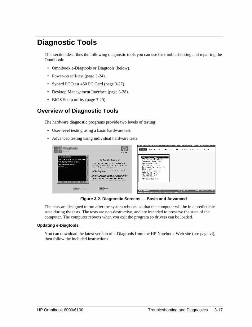
HP Omnibook 6000/6100 Troubleshooting and Diagnostics 3-17
Diagnostic Tools
This section describes the following diagnostic tools you can use for troubleshooting and repairing theOmnibook:
• Omnibook e-Diagtools or Diagtools (below).
• Power-on self-test (page 3-24).
• Sycard PCCtest 450 PC Card (page 3-27).
• Desktop Management Interface (page 3-28).
• BIOS Setup utility (page 3-29).
Overview of Diagnostic Tools
The hardware diagnostic programs provide two levels of testing:
• User-level testing using a basic hardware test.
• Advanced testing using individual hardware tests.
Figure 3-2. Diagnostic Screens — Basic and Advanced
The tests are designed to run after the system reboots, so that the computer will be in a predictablestate during the tests. The tests are non-destructive, and are intended to preserve the state of thecomputer. The computer reboots when you exit the program so drivers can be loaded.
Updating e-Diagtools
You can download the latest version of e-Diagtools from the HP Notebook Web site (see page vi),then follow the included instructions.

3-18 Troubleshooting and Diagnostics HP Omnibook 6000/6100
Running e-Diagtools
The following steps describe e-Diagtools. Diagtools steps may differ slightly.
1. Restart the computer.
2. When the HP logo appears, press F10 to start the diagnostic test.
3. When the menu appears, press ENTER to run e-DiagTools.
4. The first time you run the program, you are prompted to select the language for the program.
5. Press F2 to proceed with the basic tests.
You can also proceed directly to the advanced tests from this point by pressing CTRL-F9 (inwhich case skip to step 10, below).
6. When the Configuration Description appears, check the list of detected hardware.
Note
If a device is not detected or fails its test, it might be configured incorrectly in BIOS Setup. Youcan confirm this by running BIOS Setup and checking the settings—see “BIOS Setup Utility” onpage 3-29.
7. Run the basic test. Press F2 to start the basic hardware test.
8. To exit without running the advanced tests, press F4 to view the Support Ticket. Press F3 to exit.
9. Optional: Run the advanced tests. Press F2 to open the advanced test screen.
10. Select and run the appropriate tests. Note that individual tests do not appear if the hardware theytest is not detected. Press the following keys to run tests:
ENTER Runs the highlighted test.F5 or SPACE Marks/unmarks the highlighted test.F6 Marks/unmarks all tests in the current menu.F7 Marks/unmarks all tests in all menus.F10 Runs all marked tests.
If a test fails, the error code and description are logged, and the error code is displayedtemporarily. If several errors occur, look for patterns that might indicate a common cause. See thetable on page 3-20 for repair suggestions. Consider these suggestions in combination with othertroubleshooting information.
11. Save the Support Ticket. Press T to update and display a Support Ticket containing system andtest information.
12. When you are finished running tests, press ESC to exit the advanced tests.
13. Optional: To save the Support Ticket to a floppy disk, press F7 then ALT+C.
14. Exit. Press F3 and then any key to exit and reboot.
15. Optional for e-Diagtools only: Open the Support Ticket. In Windows, click Start, Programs,HP e-DiagTools, e-DiagTools for Windows.
16. Click View to display the Support Ticket.
17. To add information about the problem, click Comments and type the information, then click OK.
To save or print the Support Ticket, click Save As or Print.
For Diagtools, to view or edit the support ticket, run c:\Dmi\Hputils\Hpsuppt.exe.

HP Omnibook 6000/6100 Troubleshooting and Diagnostics 3-19
Note that the serial and parallel port tests are more thorough if you connect a loop-back connector tothe port before running the test for that port. See the wiring diagrams below.
141
2513
61
95
Figure 3-3. Serial and Parallel Loopback Connectors
These connectionsare not used.
Diodes are 1N4004or equivalent(IF=1A, VF=1V@1A,VR=30-400V)

3-20 Troubleshooting and Diagnostics HP Omnibook 6000/6100
Interpreting the Results
The following table lists test groups, error codes, and suggestions for follow-up actions. Consider thesesuggestions in combination with other troubleshooting information.
Table 3-3. Omnibook Diagnostic Error CodesCode Suggestions
Note: If the BIOS IC appears to be corrupted, you can tryto repair it (see page 2-33).
System Tests
0001h –0008h
Reseat or replace the CPU module.
0009h OB 6000: Replace the power supply PCA. Allmodels: Replace the CPU module. Replacethe motherboard.
0010h –0016h
Reseat or replace the CPU module.
001Eh Reseat or replace the CPU module.
0020h –002Fh
Reseat or replace the CPU module.
0030h –0040h
Replace the motherboard.
0041h Run BIOS Setup and check IRQ assignmentsfor all devices.
0050h –0063h
Replace the motherboard.
0070h Replace the CMOS battery.
0071h –0076h
Reset the system, then run BIOS Setup andcheck settings. Replace the CMOS battery.Replace the motherboard.
0077h Replace the motherboard.
0078h Reset the system, then run BIOS Setup andcheck settings. Replace the CMOS battery.Replace the motherboard.
0079h Replace the CMOS battery. Replace themotherboard.
0080h-0082h
No repair. (EISA not supported.)
0083h –008Ah
Reprogram the BIOS IC. OB 6000: Replacethe power supply PCA. All models: Replacethe motherboard.
00C0h –00CCh
Replace the CPU module.
Memory Tests
The addresses below are absolute (32-bit) addresses, andare not in the segment:offset format.
0100h –0101h
Replace the motherboard.
0102h Reprogram the BIOS IC. OB 6000: Replacethe power supply PCA. OB 6100: Replace themotherboard.
0120h Replace the SDRAM module (each 01000000hrepresents 16 MB). Replace the motherboard.
0130h Test with cache off. Replace the SDRAMmodule (each 01000000h represents 16 MB).Replace the motherboard.
0131h –0150h
Replace the SDRAM module (each 01000000hrepresents 16 MB). Replace the motherboard.
Code Suggestions
0160h Remove all but one SDRAM module andrepeat the test. Check the CPU module forshorts. Replace the CPU module. Replace themotherboard.
0170h –0172h
Replace the motherboard.
0180h Replace the SDRAM module (each 01000000hrepresents 16 MB). Replace the motherboard.
0181h Enable external cache memory through BIOSSetup. Replace the CPU module.
0182h Unload HIMEM.SYS or any programs using theextended memory allocated by HIMEM.SYS.
0183h Check installation of the SDRAM module.Replace the SDRAM module. Replace themotherboard.
0184h Check installation of the SDRAM module.Replace the SDRAM module. Replace theCPU module. Replace the motherboard.
0190h –01A0h
Replace the SDRAM module (each 01000000hrepresents 16 MB). Replace the motherboard.
01A1h –01A4h
Replace the CPU module.
01A5h Make sure cache is enabled.
01B0h Test with cache off. Replace the SDRAMmodule (each 01000000h represents 16 MB).Replace the motherboard.
01B1h –01B2h
Replace the SDRAM module (each 01000000hrepresents 16 MB). Replace the motherboard.
01B3h Replace motherboard.
Hard Disk Tests
0201h Replace the hard disk. Replace themotherboard.
0202h –0204h
Repeat the test (check test parameters).Replace the hard disk.
0205h Replace the motherboard.
0207h Run BIOS Setup and check the hard disk type.Check hard disk connectors and motherboardconnector. Replace the hard disk. Replace themotherboard.
0208h –0209h
Transient DMA error. Repeat the test.
020Ah –0211h
Repeat the test. Run SCANDISK or equivalent.
0220h Replace the motherboard.
0240h Replace the hard disk. Replace themotherboard.
0252h –0254h
Repeat the test (check test parameters).Replace the hard disk.
025Ah –0260h
Repeat the test. Run SCANDISK or equivalent,Replace the hard disk.
0265h Check hard disk connectors and motherboardconnector. Replace the hard disk. Replace themotherboard.
0275h Replace the hard disk.
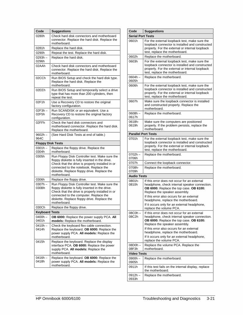
HP Omnibook 6000/6100 Troubleshooting and Diagnostics 3-21
Code Suggestions
0280h Check hard disk connectors and motherboardconnector. Replace the hard disk. Replace themotherboard.
0281h Replace the hard disk.
0290h Repeat the test. Replace the hard disk.
0293h –0296h
Replace the hard disk.
02AAh Check hard disk connectors and motherboardconnector. Replace the hard disk. Replace themotherboard.
02CCh Run BIOS Setup and check the hard disk type.Replace the hard disk. Replace themotherboard.
02EEh Run BIOS Setup and temporarily select a drivetype that has more than 200 cylinders, thenrepeat the test.
02F1h Use a Recovery CD to restore the originalfactory configuration.
02F3h –02F5h
Run SCANDISK or an equivalent. Use aRecovery CD to restore the original factoryconfiguration.
02FFh Check the hard disk connectors andmotherboard connector. Replace the hard disk.Replace the motherboard.
9602h –964C
(See Hard Disk Tests at end of table.)
Floppy Disk Tests
0301h –0304h
Replace the floppy drive. Replace themotherboard.
0305h Run Floppy Disk Controller test. Make sure thefloppy diskette is fully inserted in the drive.Check that the drive is properly installed in orconnected to the notebook. Replace thediskette. Replace floppy drive. Replace themotherboard.
0306h Replace the floppy drive.
0307h –030Bh
Run Floppy Disk Controller test. Make sure thefloppy diskette is fully inserted in the drive.Check that the drive is properly installed in orconnected to the computer. Replace thediskette. Replace floppy drive. Replace themotherboard.
030Ch Replace the floppy drive.
Keyboard Tests
0400h –0401h
OB 6000: Replace the power supply PCA. Allmodels: Replace the motherboard.
0410h –0414h
Check the keyboard flex cable connection.Replace the keyboard. OB 6000: Replace thepower supply PCA. All models: Replace themotherboard.
0415h Replace the keyboard. Replace the displayinterface PCA. OB 6000: Replace the powersupply PCA. All models: Replace themotherboard.
0416h –0418h
Replace the keyboard. OB 6000: Replace thepower supply PCA. All models: Replace themotherboard.
Code Suggestions
Serial Port Tests
0601h For the external loopback test, make sure theloopback connector is installed and constructedproperly. For the external or internal loopbacktest, replace the motherboard.
0602h Replace the motherboard.
0603h For the external loopback test, make sure theloopback connector is installed and constructedproperly. For the external or internal loopbacktest, replace the motherboard.
0604h –0605h
Replace the motherboard.
0606h For the external loopback test, make sure theloopback connector is installed and constructedproperly. For the external or internal loopbacktest, replace the motherboard.
0607h Make sure the loopback connector is installedand constructed properly. Replace themotherboard.
0608h –0617h
Replace the motherboard.
0618h-0619h
Make sure the computers are positionedproperly. If the problem persists, replace themotherboard.
Parallel Port Tests
0701h For the external loopback test, make sure theloopback connector is installed and constructedproperly. For the external or internal loopbacktest, replace the motherboard.
0702h –0706h
Replace the motherboard.
0707h Connect the loopback connector.
0708h-0709h
Replace the motherboard.
Audio Tests
0801h-0810h
If this error does not occur for an externalheadphone, check internal speaker connection.OB 6000: Replace the top case. OB 6100:Replace the speaker assembly.If this error also occurs for an externalheadphone, replace the motherboard.If it occurs only for an external headphone,replace the volume PCA.
08C0h –08C2h
If this error does not occur for an externalheadphone, check internal speaker connection.OB 6000: Replace the top case. OB 6100:Replace the speaker assembly.If this error also occurs for an externalheadphone, replace the motherboard.If it occurs only for an external headphone,replace the volume PCA.
08D0h –08F3h
Replace the volume PCA. Replace themotherboard.
Video Tests
0900h –0905h
Replace the motherboard.
0911h If this test fails on the internal display, replacethe motherboard.
0912h –0933h
Replace the motherboard.
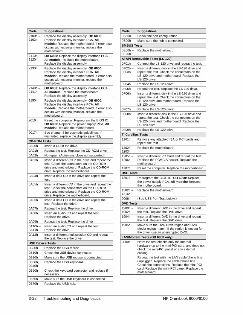
3-22 Troubleshooting and Diagnostics HP Omnibook 6000/6100
Code Suggestions
2100h –2102h
Replace the display assembly. OB 6000:Replace the display interface PCA. Allmodels: Replace the motherboard. If error alsooccurs with external monitor, replace themotherboard.
2110h –2120h
OB 6000: Replace the display interface PCA.All models: Replace the motherboard.Replace the display assembly.
2130h Replace the display assembly. OB 6000:Replace the display interface PCA. Allmodels: Replace the motherboard. If error alsooccurs with external monitor, replace themotherboard.
2140h –2141h
OB 6000: Replace the display interface PCA.All models: Replace the motherboard.Replace the display assembly.
2150h Replace the display assembly. OB 6000:Replace the display interface PCA. Allmodels: Replace the motherboard. If error alsooccurs with external monitor, replace themotherboard.
9016h Reset the computer. Reprogram the BIOS IC.OB 6000: Replace the power supply PCA. Allmodels: Replace the motherboard.
9017h See chapter 5 for cosmetic guidelines. Ifwarranted, replace the display assembly.
CD-ROM Tests
0A00h Insert a CD in the drive.
0A01h Repeat the test. Replace the CD-ROM drive.
0A02h No repair. (Automatic close not supported.)
0A03h Insert a different CD in the drive and repeat thetest. Check the connectors on the CD-ROMdrive and motherboard. Replace the CD-ROMdrive. Replace the motherboard.
0A04h Insert a data CD in the drive and repeat thetest.
0A05h Insert a different CD in the drive and repeat thetest. Check the connectors on the CD-ROMdrive and motherboard. Replace the CD-ROMdrive. Replace the motherboard.
0A06h Insert a data CD in the drive and repeat thetest. Replace the drive.
0A07h Repeat the test. Replace the drive.
0A08h Insert an audio CD and repeat the test.Replace the drive.
0A09h Repeat the test. Replace the drive.
0A10h –0A11h
Insert an audio CD and repeat the test.Replace the drive.
0A12h Insert a different multisession CD and repeatthe test. Replace the drive.
USB Device Tests
0B00h Replace the USB mouse.
0B10h Check the USB device connector.
0B20h Make sure the USB mouse is connected.
0B30h,0B40h
Replace the USB keyboard.
0B50h Check the keyboard connector and replace ifnecessary.
0B60h Make sure the USB keyboard is connected.
0B70h Replace the USB hub.
Code Suggestions
0B80h Check the port configuration.
0B90h Make sure the hub is connected.
SMBUS Tests
0E00h –0E20h
Replace the motherboard.
ATAPI Removable Tests (LS-120)
0F01h Connect the LS-120 drive and repeat the test.
0F02h –0F03h
Insert a different disk in the LS-120 drive andrepeat the test. Check the connectors on theLS-120 drive and motherboard. Replace theLS-120 drive.
0F04h Replace the LS-120 drive.
0F05h Repeat the test. Replace the LS-120 drive.
0F06h Insert a different disk in the LS-120 drive andrepeat the test. Check the connectors on theLS-120 drive and motherboard. Replace theLS-120 drive.
0F07h Replace the LS-120 drive.
0F08h Insert a different disk in the LS-120 drive andrepeat the test. Check the connectors on theLS-120 drive and motherboard. Replace theLS-120 drive.
0F09h Replace the LS-120 drive.
TI CardBus Tests
1201h Remove any attached ISA or PCI cards andrepeat the test.
1202h –1203h
Replace the motherboard.
1205h –1206h
Insert a different PC Card and repeat the test.Replace the PCMCIA socket. Replace themotherboard.
1207h Reset the computer. Replace the motherboard.
USB Tests
1301h Reprogram the BIOS IC. OB 6000: Replacethe power supply PCA. All models: Replacethe motherboard.
1302h –1316h
Replace the motherboard.
9006h (See USB Port Test below.)
DVD Tests
1900h –1902h
Insert a different DVD in the drive and repeatthe test. Replace the DVD drive.
1904h Insert a different DVD in the drive and repeatthe test. Replace the DVD drive.
1905h Make sure the DVD Drive region and DVDMedia region match. If the region is not set forthe drive, use an unencrypted DVD.
LAN/Modem Tests (OB 6000 only)
8000h Note: the test checks only the internalhardware up to the mini-PCI card, and does notcheck the mini-PCI panel or any externalcabling.Repeat the test with the LAN cable/phone lineunplugged. Replace the cable/phone line.Check the connections. Replace the mini-PCIcard. Replace the mini-PCI panel. Replace themotherboard.
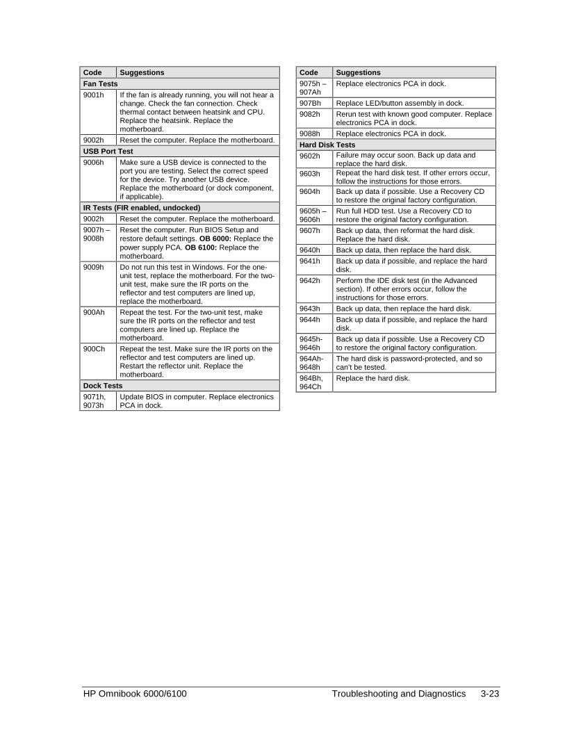
HP Omnibook 6000/6100 Troubleshooting and Diagnostics 3-23
Code Suggestions
Fan Tests
9001h If the fan is already running, you will not hear achange. Check the fan connection. Checkthermal contact between heatsink and CPU.Replace the heatsink. Replace themotherboard.
9002h Reset the computer. Replace the motherboard.
USB Port Test
9006h Make sure a USB device is connected to theport you are testing. Select the correct speedfor the device. Try another USB device.Replace the motherboard (or dock component,if applicable).
IR Tests (FIR enabled, undocked)
9002h Reset the computer. Replace the motherboard.
9007h –9008h
Reset the computer. Run BIOS Setup andrestore default settings. OB 6000: Replace thepower supply PCA. OB 6100: Replace themotherboard.
9009h Do not run this test in Windows. For the one-unit test, replace the motherboard. For the two-unit test, make sure the IR ports on thereflector and test computers are lined up,replace the motherboard.
900Ah Repeat the test. For the two-unit test, makesure the IR ports on the reflector and testcomputers are lined up. Replace themotherboard.
900Ch Repeat the test. Make sure the IR ports on thereflector and test computers are lined up.Restart the reflector unit. Replace themotherboard.
Dock Tests
9071h,9073h
Update BIOS in computer. Replace electronicsPCA in dock.
Code Suggestions
9075h –907Ah
Replace electronics PCA in dock.
907Bh Replace LED/button assembly in dock.
9082h Rerun test with known good computer. Replaceelectronics PCA in dock.
9088h Replace electronics PCA in dock.
Hard Disk Tests
9602h Failure may occur soon. Back up data andreplace the hard disk.
9603h Repeat the hard disk test. If other errors occur,follow the instructions for those errors.
9604h Back up data if possible. Use a Recovery CDto restore the original factory configuration.
9605h –9606h
Run full HDD test. Use a Recovery CD torestore the original factory configuration.
9607h Back up data, then reformat the hard disk.Replace the hard disk.
9640h Back up data, then replace the hard disk.
9641h Back up data if possible, and replace the harddisk.
9642h Perform the IDE disk test (in the Advancedsection). If other errors occur, follow theinstructions for those errors.
9643h Back up data, then replace the hard disk.
9644h Back up data if possible, and replace the harddisk.
9645h-9646h
Back up data if possible. Use a Recovery CDto restore the original factory configuration.
964Ah-9648h
The hard disk is password-protected, and socan’t be tested.
964Bh,964Ch
Replace the hard disk.

3-24 Troubleshooting and Diagnostics HP Omnibook 6000/6100
Power-On Self-Test
Note
If Quiet Boot is enabled in BIOS Setup (the default setting), press ESC during boot to see POSTmessages.
The POST (Power-On Self-Test) is a series of initialization routines and diagnostic tests that thesystem BIOS runs when the computer boots. The system BIOS will not boot the operating system ifsystem memory, the CPU, DMA, or the interrupt controller fails the POST diagnostic tests. POSTprogress is indicated by a sequence of codes, and error messages are displayed if possible.
You should not necessarily interpret the failure of one or more POST tests as a hardware, software, orfirmware failure. First, confirm the failure by performing a “clean” boot:
• Remove all accessories, including SDRAM modules, floppy drive, port replicator, PC Cards,printer, external monitor, pointing device, and keyboard.
• Provide “clean” AC power—no auto adapter or unusual AC adapter configuration.
• Press the system-off switch to start the computer from a known state.
If the computer fails to boot with a clean boot, it requires repair. If an error message appears, confirmthe problem using other diagnostic tools. Not all POST messages indicate a hardware, software, orfirmware failure—some messages are for information only.
If the BIOS detects a terminal error condition, it halts POST after issuing a terminal error beep code(see the following table). The beep code indicates the POST routine in which the terminal erroroccurred.
Table 3-4. POST Terminal-Error Beep Codes
Beep Codes* POST Description
1 One short beep before boot.
1-2 Search for option ROMs.
1-2-2-3 BIOS ROM checksum.
1-3-1-1 Test DRAM refresh.
1-3-1-3 Test 8742 Keyboard Controller (part of power supply PCA).
1-3-4-1 RAM failure on address line xxxx.
1-3-4-3 RAM failure on data bits xxxx of low byte of memory bus.
1-4-1-1 RAM failure on data bits xxxx of high byte of memory bus.
2-1-2-3 Check ROM copyright notice.
2-2-3-1 Test for unexpected interrupts.
1 long-2 short Improper video configuration (check display DIP switches, replace displayinterface PCA) or external ROM checksum failure.
1 long-5 short Display DIP switches and EEPROM settings do not match (check DIP switchsettings, reprogram EEPROM) (Omnibook 6000 only).
* Up to four groups of short beeps, except as noted.

HP Omnibook 6000/6100 Troubleshooting and Diagnostics 3-25
The following table lists POST messages and explanations for reported problems. If the system failsafter you make changes in BIOS Setup, reset the computer, enter BIOS Setup, and install the defaultsor correct the error.
Table 3-5. POST Messages
Message Description0200 Failure Fixed Disk
Fixed disk is not working or not configured properly. Make sure the fixed disk is attachedproperly. Run Setup. Find out if the fixed-disk type is correctly identified.
0210 Stuck keyStuck key on keyboard.
0211 Keyboard errorKeyboard not working.
0212 Keyboard Controller FailedKeyboard controller failed test. May require replacing power supply PCA (contains keyboardcontroller).
0213 Keyboard locked – Unlock key switchUnlock the system to proceed.
0220 Monitor type does not match CMOS – Run SETUPMonitor type not correctly identified in Setup
0230 Shadow RAM Failed at offset: nnnnShadow RAM failed at offset nnnn of the 64k block at which the error was detected.
0231 System RAM Failed at offset: nnnnSystem RAM failed at offset nnnn of in the 64k block at which the error was detected.
0232 Extended RAM Failed at offset: nnnnExtended memory not working or not configured properly at offset nnnn. Update to the latestBIOS version.
0250 System battery is dead – Replace and run SETUPThe CMOS clock battery indicator shows the battery is dead. Connect the AC adapter for atleast 24 hours; replace the motherboard.
0251 System CMOS checksum bad – Default configuration usedSystem CMOS has been corrupted or modified incorrectly, perhaps by an applicationprogram that changes data stored in CMOS. The BIOS installed Default Setup Values. If youdo not want these values, enter Setup and enter your own values. If the error persists, checkthe system battery. Connect the AC adapter for at least 24 hours; replace the motherboard.
0260 System timer errorThe timer test failed. Requires replacement of motherboard.
0270 Real time clock errorReal-time clock fails BIOS test. May require replacement of motherboard.
0280 Previous boot incomplete – Default configuration usedPrevious POST did not complete successfully. POST loads default values and offers to runSetup. If the failure was caused by incorrect values and they are not corrected, the next bootwill likely fail. This error is cleared the next time the system is booted.
0281 Memory Size found by POST differed from CMOSMemory size found by POST differed from CMOS.
02B0 Diskette drive A error02B1 Diskette drive B error
Drive A: or B: is present but fails the BIOS POST diskette tests. Make sure the drive isdefined with the proper diskette type in Setup and that the diskette drive is attached correctly.
02B2 Incorrect Drive A type – run SETUPType of floppy drive A: not correctly identified in Setup.
02B3 Incorrect Drive B type – run SETUPType of floppy drive B: not correctly identified in Setup.
02D0 System cache error – Cache disabledRAM cache failed and BIOS disabled the cache. May require replacement of motherboard. Adisabled cache slows system performance considerably.
02F0: CPU ID:CPU socket number for Multi-Processor error.
02F4: EISA CMOS not writeableServerBIOS2 test error: Cannot write to EISA CMOS.

3-26 Troubleshooting and Diagnostics HP Omnibook 6000/6100
Message Description02F5: DMA Test Failed
ServerBIOS2 test error: Cannot write to extended DMA (Direct Memory Access) registers.
02F6: Software NMI FailedServerBIOS2 test error: Cannot generate software NMI (Non-Maskable Interrupt).
02F7: Fail-Safe Timer NMI FailedServerBIOS2 test error: Fail-Safe Timer takes too long.
device Address ConflictAddress conflict for specified device.
Allocation Error for: deviceRun ISA or EISA Configuration Utility to resolve resource conflict for the specified device.
CD ROM DriveCD ROM Drive identified.
Entering SETUP ...Starting Setup program
Failing Bits: nnnnThe hex number nnnn is a map of the bits at the RAM address which failed the memory test.Each 1 (one) in the map indicates a failed bit. See errors 230, 231, or 232 above for offsetaddress of the failure in System, Extended, or Shadow memory.
Fixed Disk nFixed disk n (0–3) identified.
Invalid System Configuration DataProblem with NVRAM (CMOS) data.
I/O device IRQ conflictI/O device IRQ conflict error.
PS/2 Mouse Boot Summary Screen:PS/2 Mouse installed.
nnnn kB Extended RAM PassedWhere nnnn is the amount of RAM in kilobytes successfully tested.
nnnn Cache SRAM PassedWhere nnnn is the amount of system cache in kilobytes successfully tested.
nnnn kB Shadow RAM PassedWhere nnnn is the amount of shadow RAM in kilobytes successfully tested.
nnnn kB System RAM PassedWhere nnnn is the amount of system RAM in kilobytes successfully tested.
Operating system not foundOperating system cannot be located on either drive A: or drive C:. Enter Setup and see iffixed disk and drive A: are properly identified.
Parity Check 1 nnnnParity error found in the system bus. BIOS attempts to locate the address and display it onthe screen. If it cannot locate the address, it displays ????. Parity is a method for checkingerrors in binary data. A parity error indicates that some data has been corrupted.
Parity Check 2 nnnnParity error found in the I/O bus. BIOS attempts to locate the address and display it on thescreen. If it cannot locate the address, it displays ????.
Press <F1> to resume, <F2> to Setup, <F3> for previousDisplayed after any recoverable error message. Press <F1> to start the boot process or <F2>to enter Setup and change the settings. Press <F3> to display the previous screen (usuallyan initialization error of an Option ROM, such as an add-on card). Write down and follow theinformation shown on the screen.
Press <F2> to enter SetupOptional message displayed during POST.
PS/2 Mouse:PS/2 mouse identified.
System BIOS shadowedSystem BIOS copied to shadow RAM.
UMB upper limit segment address: nnnnDisplays the address nnnn of the upper limit of Upper Memory Blocks, indicating releasedsegments of the BIOS which can be reclaimed by a virtual memory manager.
Video BIOS shadowedVideo BIOS copied to shadow RAM.

HP Omnibook 6000/6100 Troubleshooting and Diagnostics 3-27
Sycard PCCtest 450 CardBus Card (Optional)
The PCCtest 450 CardBus Card (version 1.05) available from Sycard Technology is the onlyrecommended diagnostic tool that tests the functionality of the PCMCIA slots using a PCMCIA card.It is a Type II CardBus Card that works with compatible test software to exercise PCMCIA functions.(For details, see the Sycard Technology Web site: http://www.sycard.com.) The PCCtest 450 productcontains these components:
• PCCtest 450 CardBus Card, version 1.05.
• PCCtest 450 software disk. (Software updates are available at the Sycard Technology Web site:http://www.sycard.com.)
• Configuration headers (PC Card/16-bit and CardBus/32-bit) that attach to the card.
In addition, you will need this:
• CardBus extender card (such as the Sycard PCCextend 70) to avoid wear on the Sycard PCMCIAconnector.
The Sycard PCCtest 450 provides the following tests. See the Sycard documentation for details aboutrunning the tests.
Table 3-6. Sycard PCCtest Commands
Slot PCMCIA PC Card (16-bit) test(PC Card configuration header)
CardBus (32-bit) test(CardBus configuration header)
Omnibook 6000/6100(PCI1420)
UpperLower
PCT450 -1 -v -b75PCT450 -0 -v -b75
TESTCB -1 -v -b75 -jsD000:0TESTCB -0 -v -b75 -jsD000:0
3-28 Troubleshooting and Diagnostics HP Omnibook 6000/6100
Desktop Management Interface (DMI)
The Desktop Management Interface (Windows 98) and Windows Management Instrumentation(Windows 2000) are basically sets of rules for accessing information about a computer. DMI/WMIallows an application to determine, for example, the operating system being used, which hardware andsoftware components are in the computer, and possibly whether any of the components needreplacing. A local or remote application can use the DMI/WMI interface to check which hardware andsoftware components are installed on your computer, and may be able to tell how well they areworking or if they need replacement.
Installing the DMI Package
The DMI package is either preinstalled on the computer’s hard disk or can be downloaded fromhttp://www.hp.com/toptools (the contents are the same in both cases). The package must be properlyinstalled before it can be used.
To install the DMI/WMI preloaded on the hard disk:
1. Start Windows, if it is not already running.
2. Click Start, Programs, HP Toptools, Setup.
Using DMI/WMI
For a complete description of how to use DMI/WMI, see the following documentation provided withthe computer:
• A README.TXT file: click Start, Programs, HP Toptools, Read me.
• A Windows online help file describing Hewlett-Packard’s implementation of DMI/WMI (groupand attribute definitions): click Start, Programs, HP Toptools, HP Toptools Help.
Uninstalling the DMI/WMI Package
1. Click Start, Programs, HP Toptools, Uninstall HP Toptools (Windows 98) or Uninstall WMI(Windows 2000).
2. Restart the computer.

HP Omnibook 6000/6100 Troubleshooting and Diagnostics 3-29
BIOS Setup Utility
The BIOS Setup utility provides access to basic configuration settings. It is independent of theoperating system.
Running the BIOS Setup Utility
1. Close all applications, then click Start, Shut Down, Reboot. (If necessary, you can pressCTRL+ALT+DEL to reboot.)
2. When the HP logo appears, press F2 to enter the BIOS Setup utility.
3. The pointing devices are not active in BIOS Setup, so you will need to use the keyboard tonavigate:
• Press the LEFT and RIGHT arrow keys to move among menus.
• Press the UP and DOWN arrow keys to move among parameters in a menu.
• Press F5 or F6 to move through values for the current parameter, or press ENTER to change asetting.
4. After you select the options you want, press F10 or use the Exit menu to exit BIOS Setup.
If the settings cause a conflict between devices during reboot, the system prompts you to runBIOS Setup, and marks the conflicting settings.
Table 3-7. BIOS Setup Menus and Parameters
This table provides BIOS setup menus and parameters for OB 6100 models. Specifications vary forOmnibook 6000 models.Omnibook 6100: Introduced with BIOS version EB.M1.00 (Summer 2001).Omnibook 6000: Introduced with BIOS version EA.M1.00 (Spring 2000).
Main Menu DefaultBIOS Revision Shows the current BIOS version. Detected
automatically.System Time Sets the date using dd/mm/yy format (except English, which
uses mm/dd/yy format).System Date Sets the date using mm/dd/yy (English) or dd/mm/yy format.Internal Hard Disk Sets the hard disk drive type and various parameters. Detected
automatically.Quiet Boot When enabled, hides summary of power-on self-test and
messages during boot.Enabled
Video Display Device Sets whether the built-in display automatically switches to anexternal display, if one is detected.
Auto
Video Expansion When enabled, the video image covers the entire display inlower resolution modes. When disabled, the video image iscentered in the display.
Disabled
Primary Video Adapter Sets whether the computer automatically switches to anexternal video adapter connected to the docking system, ifone is detected.
Auto
Television Type Controls the signal format (NTSC or PAL) output by theS-video port when Windows is not running.
NTSC
System Memory Shows the system memory size. 640 KBExtended Memory Shows the extended memory size. Detected
automatically.

3-30 Troubleshooting and Diagnostics HP Omnibook 6000/6100
Unique Dock ID Sets whether the computer creates a unique hardwareprofile for each dock (Enabled) or uses a common profile forall docks (Disabled).
Enabled
UUID Displays the value of the 16-byte UUID (Universally UniqueID) as 32 hex characters.
Detectedautomatically
System Devices Menu Default
PS/2 Pointing Devices Disables the internal pointing devices when an external PS/2mouse is connected.
Auto
External Fn Key Sets whether left CTRL+left ALT on an external keyboard isinterpreted as the Fn key.
Enabled
FDD Controller Enables the floppy drive. Enabled
Legacy USB Support Enables BIOS support for USB mouse, keyboard, and floppydisk drive.
Enabled
Internal LAN Enables the internal (wired) LAN. Enabled
Mini PCI Slot 1 Enables the PCI slot normally used for a wireless LAN. Enabled
Mini PCI Slot 2 Enables the PCI slot normally used for a modem, which islocated under the cover on the bottom of unit. (Does notaffect Ambit modem.)
Enabled
Serial port Enables the serial port. Enabled
Base I/O address Sets the I/O address. 3F8h
Interrupt Sets the interrupt. IRQ4
Infrared port Enables the infrared port. Disabled
Mode Sets the hardware to support FIR (Fast IR) or SIR (StandardIR) infrared communications.
FIR
Base I/O address Sets the I/O address. 2F8h
Interrupt Sets the interrupt. IRQ3
DMA channel Sets the DMA channel for Fast IR (FIR) mode. DMA0
Parallel Port Enables the parallel port. Enabled
Mode Sets the port to output only, bi-directional, EPP, or ECP. ECP
Base I/O address Sets the I/O address. 378h
Interrupt Sets the interrupt. IRQ7
DMA channel Sets the DMA channel for ECP mode. DMA1
Security Menu Default
User Password is Shows if a user password is set. Clear
Administrator Passwordis
Shows if an administrator password is set. Clear
Set User Password Press ENTER to set, change, or clear the user password.The password can have no more than 8 characters (0-9,A-Z), and cannot include special or accented characters.
Enter
Set AdministratorPassword
Press ENTER to set, change, or clear the administratorpassword, which protects BIOS Setup settings. Thepassword can have no more than 8 characters (0-9, A-Z),and cannot include special or accented characters.
Enter
Boot Sets whether a user password is required when thecomputer boots. Requires the administrator password forchanges.
Enabled
Resume* Sets whether a user password is required when resumingfrom Standby or Hibernate mode. Requires the administratorpassword for changes. (Windows 98 only.)
Enabled

HP Omnibook 6000/6100 Troubleshooting and Diagnostics 3-31
Undock* Sets whether a user password is required when undockingthe computer. Requires the administrator password forchanges. (Windows 98 only.)
Disabled
Internal hard disk drivelock*
Encodes the current user password (or administratorpassword if that is the only password set) on the hard diskdrive.
Disabled
Removable Device Boot Sets whether the computer will attempt to boot from a floppydrive or other removable device.
Enabled
* Resume, Undock, and Internal hard disk drive lock options are available only if the Boot option is enabled.
Power Menu DefaultWindows 2000 uses only the settings marked with *. Windows 98 uses only the settings marked with * or **. Allother settings in the Power menu are ignored.
Power ManagementMode
Disables time-outs, selects a combination of time-outs, orallows customized time-outs.
Max. PowerSavings
Suspend Time-out Sets the period of inactivity after which the computer goesfrom Display-off to Standby power mode.
4 minutes
Hibernate Time-out** Sets whether the computer goes from Standby to Hibernatepower mode after the indicated period of inactivity. (SkipsStandby mode if the suspend time-out is disabled.)
4 hours
Hard Disk Time-out Sets the period of hard disk inactivity after which the internalhard disk (and any hard disk drive in the plug-in module bay)stops spinning.
2 minutes
Time-out on AC Sets whether power management time-outs occur while theAC adapter is connected.
Disabled
Lid Switch Mode Sets the action that occurs if the computer’s lid is closed. Turn off LCD
Resume On Serial Ring Sets whether the system resumes if it received a ring signal. Disabled
Resume On Time of Day Sets whether the system resumes at a defined time of day. Disabled
Resume Time Sets the 24-hour time when the system resumes from ifResume On Time of Day is enabled.
Auto Low-BatteryHibernate**
Sets whether the computer goes to Hibernate mode orcontinues running when the battery drains to its critically lowlevel.
Enabled
Graphics Mode* Sets the graphics system for maximum 3D performance orto save power.
Max.Performance
Backlight Mode* When switching to battery power, sets whether the displaybrightness reverts to the previous battery-power brightness(Auto Restore) or to a very low brightness to save power(Auto Dim).
Auto Restore
Auto Suspend onUndock*
Sets whether the computer suspends to Standby powermode after undocking.
When LidClosed
Auto Turn-On on Dock* Sets whether the computer turns on after docking. Enabled
* Windows 98 and 2000 use these settings.** Windows 98 uses these additional settings.
Boot Menu Default
+Hard Disk+Removable DeviceCD-ROM/DVD DriveIntel Boot Agent
Shows the order of boot devices, with “+” indicating a devicecategory. Move the entries to change the order. If thecomputer has more than one device in a category, you canselect the one scanned. Intel Boot Agent provides disklessboot from a network server.
1. Hard Disk2. RemovableDevice3. CD-ROM/DVDdrive4. Intel BootAgent

3-32 Troubleshooting and Diagnostics HP Omnibook 6000/6100
Exit Menu
Save Changes and Exit Saves Setup changes, then exits and reboots.
Discard Changes andExit
Discards any Setup changes made since last save, thenexits and reboots. Does not affect password, date, or timechanges.
Get Default Values Restores default settings, and remains in Setup. Does notaffect password, date, or time changes.
Load Previous Values Discards any Setup changes made since last save, andremains in Setup. Does not affect password, date, or timechanges.
Save Changes Saves Setup changes, and remains in Setup. Securitysettings are saved when changed.

HP Omnibook 6000/6100 Replaceable Parts 4-1
4
Replaceable Parts
This chapter contains an exploded view of the Omnibook and the following lists of parts:
• Omnibook replaceable parts (page 4-3).
• Accessory replacement parts (page 4-8).
• Part number reference (page 4-9).
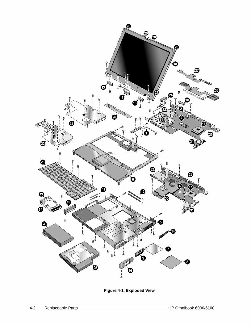
4-2 Replaceable Parts HP Omnibook 6000/6100
Figure 4-1. Exploded View
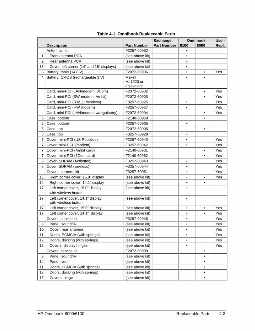
HP Omnibook 6000/6100 Replaceable Parts 4-3
Table 4-1. Omnibook Replaceable Parts
Exchange Omnibook User-Description Part Number Part Number 6100 6000 Repl.Antennas, kit F3257-60952 •
1 Front antenna PCA (see above kit) •2 Rear antenna PCA (see above kit) •
15 Cover, left corner (14” and 15” displays) (see above kit) •3 Battery, main (14.8 V) F2072-60906 • • Yes4 Battery, CMOS (rechargeable 3 V) Maxell
ML1220 orequivalent
• •
Card, mini-PCI (LAN/modem, 3Com) F2072-60902 • YesCard, mini-PCI (SW modem, Ambit) F2072-60903 • YesCard, mini-PCI (802.11 wireless) F3257-60925 • YesCard, mini-PCI (HW modem) F3257-60927 • YesCard, mini-PCI (LAN/modem w/regulatory) F2072-60994 • Yes
5 Case, bottom F2140-60950 •5 Case, bottom F3257-60935 •6 Case, top F2072-60905 •6 Case, top F3257-60928 •7 Cover, mini-PCI (US Robotics) F3257-60940 • Yes7 Cover, mini-PCI (modem) F3257-60942 • Yes7 Cover, mini-PCI (Ambit card) F2140-60961 • Yes7 Cover, mini-PCI (3Com card) F2140-60962 • Yes8 Cover, SDRAM (Actiontec) F3257-60943 • Yes8 Cover, SDRAM (wireless) F3257-60944 • Yes
Covers, corners, kit F3257-60951 • Yes16 Right corner cover, 15.0” display (see above kit) • • Yes16 Right corner cover, 14.1” display (see above kit) • •17 Left corner cover, 15.0” display,
with wireless button(see above kit) •
17 Left corner cover, 14.1” display,with wireless button
(see above kit) •
17 Left corner cover, 15.0” display (see above kit) • • Yes17 Left corner cover, 14.1” display (see above kit) • • Yes
Covers, service kit F3257-60948 • Yes9 Panel, sound/IR (see above kit) • Yes
10 Cover, rear antenna (see above kit) • Yes11 Doors, PCMCIA (with springs) (see above kit) • Yes12 Doors, docking (with springs) (see above kit) • Yes13 Covers, display hinges (see above kit) • Yes
Covers, service kit F2072-60999 •9 Panel, sound/IR (see above kit) •
14 Panel, vent (see above kit) •11 Doors, PCMCIA (with springs) (see above kit) •12 Doors, docking (with springs) (see above kit) •13 Covers, hinge (see above kit) •

4-4 Replaceable Parts HP Omnibook 6000/6100
Exchange Omnibook User-Description Part Number Part Number 6100 6000 Repl.Covers, user kit F2140-60914 • Yes
7 Cover, mini-PCI (no modem) (see above kit) • Yes8 Cover, SDRAM (see above kit) • Yes
15 Cover, left corner (14” and 15” displays) (see above kit) • Yes16 Cover, right corner (14” and 15” displays) (see above kit) • Yes17 CPU module, 600 MHz, Pentium III 1821-5688 F1979-69101 •17 CPU module, 650 MHz, Pentium III 1821-5689 F1980-69101 •17 CPU module, 650 MHz, Celeron 1821-5867 F2111-69102 •17 CPU module, 700 MHz, Pentium III 1821-5690 F2072-69102 •17 CPU module, 750 MHz, Celeron 1821-8826 F2140-69104 •17 CPU,Module, 800 MHz, Pentium III 1821-8570 F2140-69102 •17 CPU,Module, 850 MHz, Pentium III 1821-8571 F2140-69103 •17 CPU,Module, 900 MHz, Pentium III 1822-0098 F2140-69105 •17 CPU,Module, 933 MHz, Pentium III-M
Tualatin1822-0400 F3257-69004 •
17 CPU,Module, 1 GHz, Pentium III 1822-0099 F2140-69106 •17 CPU Module, 1 GHz, Pentium III-M Tualatin 1822-0395 F3257-69005 •17 CPU,Module, 1.133 GHz, Pentium III-M
Tualatin1822-0392 F3257-69006 •
18 Display assembly, 14.1” XGA F2072-60917 F2072-60917 •18 Display assembly, 14.1" XGA F3257-60937 F3257-69037 •18 Display assembly, 15.0” XGA F2072-60918 F2072-60918 •18 Display assembly, 15.0" SXGA+ F3257-60939 F3257-69039 •18 Display assembly, 15.0" SXGA+ F2140-60949 F2140-69049 •19 Drive, hard disk (5 GB, 9.5 mm, Fujitsu) 0950-3905 F2072-69106 • Yes19 Drive, hard disk (5 GB, 9.5 mm, IBM) 0950-3933 F1660-69111 • Yes19 Drive, hard disk (5 GB, 9.5 mm, Hitachi) 0950-3963 F2072-69114 • Yes19 Drive, hard disk (6 GB, 9.5 mm, Fujitsu) 0950-3731 • Yes19 Drive, hard disk (6 GB, 9.5 mm, Hitachi) 0950-3732 F1660-69108 • Yes19 Drive, hard disk (6 GB, 9.5 mm, Toshiba) 0950-4010 F2072-69112 • Yes19 Drive, hard disk (6 GB, 9.5 mm, Hitachi) 0950-4032 F1629-69056 • Yes19 Drive, hard disk (7.5 GB, 9.5 mm, IBM) 0950-4030 F2112-69003 • Yes19 Drive, hard disk (10 GB, 9.5 mm, Hitachi) 0950-3903 F2072-69108 • Yes19 Drive, hard disk (10 GB, 9.5 mm, IBM) 0950-3934 F1660-69112 • Yes19 Drive, hard disk (10 GB, 9.5 mm, Hitachi) 0950-3964 F1664-69002 • Yes19 Drive, hard disk (10 GB, 9.5 mm, Toshiba) 0950-3985 F2072-69109 • Yes19 Drive, hard disk (10 GB, 9.5 mm, IBM Diablo) 0950-4166 F3257-69100 • • Yes19 Drive, hard disk (10 GB, 9.5 mm, Toshiba) 0950-4178 F3257-69101 • • Yes19 Drive, hard disk (10 GB, 9.5 mm, Hitachi) 0950-4213 F3257-69104 • • Yes19 Drive, hard disk (12 GB, 9.5 mm, Toshiba) 0950-3725 F1660-69110 • Yes19 Drive, hard disk (20 GB 9.5 mm, Hitachi) 0950-3965 F2072-69113 • Yes19 Drive, hard disk (20 GB, 9.5 mm, Toshiba) 0950-3986 F2072-69111 • Yes19 Drive, hard disk (20 GB, 9.5 mm, IBM Diablo) 0950-4163 F2072-69114 • • Yes19 Drive, hard disk (20 GB, 9.5 mm, Toshiba) 0950-4171 F3257-69102 • • Yes19 Drive, hard disk (20 GB, 9.5 mm, Hitachi) 0950-4193 F3257-69105 • • Yes19 Drive, hard disk (30 GB, 12.5 mm, IBM) 0950-3936 F2072-69110 • Yes19 Drive, hard disk (30 GB, 9.5 mm, IBM Diablo) 0950-4162 F2072-69115 • • Yes19 Drive, hard disk (30 GB, 9.5 mm, Hitachi) 0950-4168 F3257-69106 • • Yes
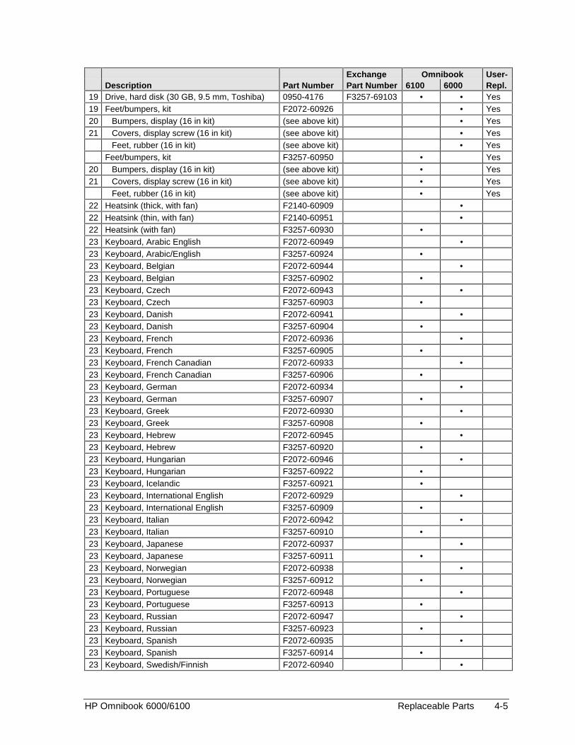
HP Omnibook 6000/6100 Replaceable Parts 4-5
Exchange Omnibook User-Description Part Number Part Number 6100 6000 Repl.
19 Drive, hard disk (30 GB, 9.5 mm, Toshiba) 0950-4176 F3257-69103 • • Yes19 Feet/bumpers, kit F2072-60926 • Yes20 Bumpers, display (16 in kit) (see above kit) • Yes21 Covers, display screw (16 in kit) (see above kit) • Yes
Feet, rubber (16 in kit) (see above kit) • YesFeet/bumpers, kit F3257-60950 • Yes
20 Bumpers, display (16 in kit) (see above kit) • Yes21 Covers, display screw (16 in kit) (see above kit) • Yes
Feet, rubber (16 in kit) (see above kit) • Yes22 Heatsink (thick, with fan) F2140-60909 •22 Heatsink (thin, with fan) F2140-60951 •22 Heatsink (with fan) F3257-60930 •23 Keyboard, Arabic English F2072-60949 •23 Keyboard, Arabic/English F3257-60924 •23 Keyboard, Belgian F2072-60944 •23 Keyboard, Belgian F3257-60902 •23 Keyboard, Czech F2072-60943 •23 Keyboard, Czech F3257-60903 •23 Keyboard, Danish F2072-60941 •23 Keyboard, Danish F3257-60904 •23 Keyboard, French F2072-60936 •23 Keyboard, French F3257-60905 •23 Keyboard, French Canadian F2072-60933 •23 Keyboard, French Canadian F3257-60906 •23 Keyboard, German F2072-60934 •23 Keyboard, German F3257-60907 •23 Keyboard, Greek F2072-60930 •23 Keyboard, Greek F3257-60908 •23 Keyboard, Hebrew F2072-60945 •23 Keyboard, Hebrew F3257-60920 •23 Keyboard, Hungarian F2072-60946 •23 Keyboard, Hungarian F3257-60922 •23 Keyboard, Icelandic F3257-60921 •23 Keyboard, International English F2072-60929 •23 Keyboard, International English F3257-60909 •23 Keyboard, Italian F2072-60942 •23 Keyboard, Italian F3257-60910 •23 Keyboard, Japanese F2072-60937 •23 Keyboard, Japanese F3257-60911 •23 Keyboard, Norwegian F2072-60938 •23 Keyboard, Norwegian F3257-60912 •23 Keyboard, Portuguese F2072-60948 •23 Keyboard, Portuguese F3257-60913 •23 Keyboard, Russian F2072-60947 •23 Keyboard, Russian F3257-60923 •23 Keyboard, Spanish F2072-60935 •23 Keyboard, Spanish F3257-60914 •23 Keyboard, Swedish/Finnish F2072-60940 •
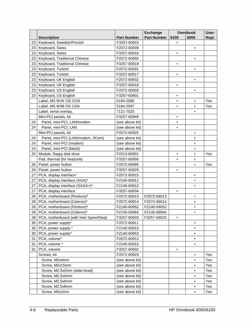
4-6 Replaceable Parts HP Omnibook 6000/6100
Exchange Omnibook User-Description Part Number Part Number 6100 6000 Repl.
23 Keyboard, Swedish/Finnish F3257-60915 •23 Keyboard, Swiss F2072-60939 •23 Keyboard, Swiss F3257-60916 •23 Keyboard, Traditional Chinese F2072-60950 •23 Keyboard, Traditional Chinese F3257-60919 •23 Keyboard, Turkish F2072-60931 •23 Keyboard, Turkish F3257-60917 •23 Keyboard, UK English F2072-60932 •23 Keyboard, UK English F3257-60918 •23 Keyboard, US English F2072-60928 •23 Keyboard, US English F3257-60901 •
Label, MS W2K OS COA 5184-2085 • • YesLabel, MS W98 OS COA 5184-2097 • • YesLabel, serial overlay, 7121-7525 •Mini-PCI panels, kit F3257-60949 •
24 Panel, mini-PCI, LAN/modem (see above kit) •24 Panel, mini-PCI, LAN (see above kit) •
Mini-PCI panels, kit F2072-60925 •24 Panel, mini-PCI (LAN/modem, 3Com) (see above kit) •24 Panel, mini-PCI (modem) (see above kit) •24 Panel, mini-PCI (blank) (see above kit) •25 Module, floppy disk drive F2013-60901 • • Yes
Pad, thermal (for heatsink) F3257-60956 • •26 Panel, power button F2072-60995 • Yes26 Panel, power button F3257-60929 •27 PCA, display interface* F2072-60915 •27 PCA, display interface (XGA)* F2140-60911 •27 PCA, display interface (SXGA+)* F2140-60912 •27 PCA, display interface F3257-60934 •28 PCA, motherboard (Pentium)* F2072-60913 F2072-69013 •28 PCA, motherboard (Celeron)* F2072-60914 F2072-69014 •28 PCA, motherboard (Pentium)* F2140-60952 F2140-69052 •28 PCA, motherboard (Celeron)* F2140-60964 F2140-69064 •28 PCA, motherboard (with Intel SpeedStep) F3257-60933 F3257-69033 •30 PCA, power supply* F2072-60911 •30 PCA, power supply * F2140-60910 •30 PCA, power supply* F2140-60953 •31 PCA, volume* F2072-60912 •31 PCA, volume * F2140-60915 •31 PCA, volume F3257-60932 •
Screws, kit F2072-60923 • YesScrew, M2x4mm (see above kit) • YesScrew, M2x15mm (see above kit) • YesScrew, M2.5x2mm (wide-head) (see above kit) • YesScrew, M2.5x4mm (see above kit) • YesScrew, M2.5x6mm (see above kit) • YesScrew, M2.5x8mm (see above kit) • YesScrew, M3x2mm (see above kit) • Yes

HP Omnibook 6000/6100 Replaceable Parts 4-7
Exchange Omnibook User-Description Part Number Part Number 6100 6000 Repl.Screws, kit F3257-60947 • Yes
Screw, M2x4mm (see above kit) • YesScrew, M2x13mm (see above kit) • YesScrew, M2x15mm (see above kit) • YesScrew, M2.5x2mm (wide-head) (see above kit) • YesScrew, M2x3mm (see above kit) • YesScrew, M2.5x4mm (see above kit) • YesScrew, M2.5x5mm (see above kit) • YesScrew, M2.5x6mm (see above kit) • YesScrew, M2.5x8mm (see above kit) • YesScrew, M2.5x17mm (see above kit) • YesScrew, M3x3mm (see above kit) • YesScrew, M3x6mm (see above kit) • Yes
SDRAM module, 32 MB, SODIMM (100 MHz) 1818-7950 • YesSDRAM module, 64 MB, SODIMM (100 MHz) 1818-7951 F1660-69103 • YesSDRAM module, 128 MB, SODIMM (100 MHz) 1818-7952 F1660-69104 • YesSDRAM module, 256 MB, SODIMM (100 MHz) 1818-7953 F1654-69101 • YesSDRAM module, 64 MB, SODIMM (133 MHz) 1818-8505 • YesSDRAM module, 64 MB, SODIMM (133 MHz) 1818-8510 • • YesSDRAM module, 128 MB, SODIMM (133 MHz) 1818-8503 • YesSDRAM module, 128 MB, SODIMM (133 MHz) 1818-8504 • YesSDRAM module, 256 MB, SODIMM (133 MHz) 1818-8534 • YesSDRAM module, 256 MB, SODIMM (133 MHz) 1818-8635 F3257-69003 • YesSDRAM module, 512 MB, SODIMM (133 MHz) 1818-8604 F2298-69001 • Yes
32 Socket, PCMCIA F2072-60919 • •33 Speaker assembly F3257-60936 •
Tray, business card F2072-60921 • • YesTray, docking E F2012-60901 • • Yes
34 Tray, hard disk drive F2072-60909 • Yes34 Tray, hard disk drive F3257-60931 • Yes* See “Table 2-5. Motherboard and PCA Compatibility” on page 2-28.
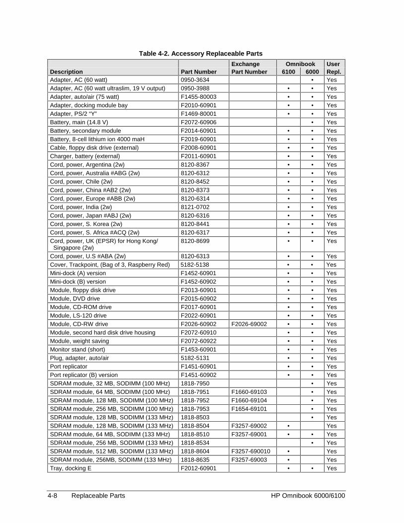
4-8 Replaceable Parts HP Omnibook 6000/6100
Table 4-2. Accessory Replaceable Parts
Exchange Omnibook UserDescription Part Number Part Number 6100 6000 Repl.Adapter, AC (60 watt) 0950-3634 • YesAdapter, AC (60 watt ultraslim, 19 V output) 0950-3988 • • YesAdapter, auto/air (75 watt) F1455-80003 • • YesAdapter, docking module bay F2010-60901 • • YesAdapter, PS/2 “Y” F1469-80001 • • YesBattery, main (14.8 V) F2072-60906 • YesBattery, secondary module F2014-60901 • • YesBattery, 8-cell lithium ion 4000 maH F2019-60901 • • YesCable, floppy disk drive (external) F2008-60901 • • YesCharger, battery (external) F2011-60901 • • YesCord, power, Argentina (2w) 8120-8367 • • YesCord, power, Australia #ABG (2w) 8120-6312 • • YesCord, power, Chile (2w) 8120-8452 • • YesCord, power, China #AB2 (2w) 8120-8373 • • YesCord, power, Europe #ABB (2w) 8120-6314 • • YesCord, power, India (2w) 8121-0702 • • YesCord, power, Japan #ABJ (2w) 8120-6316 • • YesCord, power, S. Korea (2w) 8120-8441 • • YesCord, power, S. Africa #ACQ (2w) 8120-6317 • • YesCord, power, UK (EPSR) for Hong Kong/ Singapore (2w)
8120-8699 • • Yes
Cord, power, U.S #ABA (2w) 8120-6313 • • YesCover, Trackpoint, (Bag of 3, Raspberry Red) 5182-5138 • • YesMini-dock (A) version F1452-60901 • • YesMini-dock (B) version F1452-60902 • • YesModule, floppy disk drive F2013-60901 • • YesModule, DVD drive F2015-60902 • • YesModule, CD-ROM drive F2017-60901 • • YesModule, LS-120 drive F2022-60901 • • YesModule, CD-RW drive F2026-60902 F2026-69002 • • YesModule, second hard disk drive housing F2072-60910 • • YesModule, weight saving F2072-60922 • • YesMonitor stand (short) F1453-60901 • • YesPlug, adapter, auto/air 5182-5131 • • YesPort replicator F1451-60901 • • YesPort replicator (B) version F1451-60902 • • YesSDRAM module, 32 MB, SODIMM (100 MHz) 1818-7950 • YesSDRAM module, 64 MB, SODIMM (100 MHz) 1818-7951 F1660-69103 • YesSDRAM module, 128 MB, SODIMM (100 MHz) 1818-7952 F1660-69104 • YesSDRAM module, 256 MB, SODIMM (100 MHz) 1818-7953 F1654-69101 • YesSDRAM module, 128 MB, SODIMM (133 MHz) 1818-8503 • YesSDRAM module, 128 MB, SODIMM (133 MHz) 1818-8504 F3257-69002 • YesSDRAM module, 64 MB, SODIMM (133 MHz) 1818-8510 F3257-69001 • • YesSDRAM module, 256 MB, SODIMM (133 MHz) 1818-8534 • YesSDRAM module, 512 MB, SODIMM (133 MHz) 1818-8604 F3257-690010 • YesSDRAM module, 256MB, SODIMM (133 MHz) 1818-8635 F3257-69003 • YesTray, docking E F2012-60901 • • Yes

HP Omnibook 6000/6100 Replaceable Parts 4-9
Table 4-3. Part Number Reference
Exchange Omnibook User-Part Number Part Number Description 6100 6000 Repl.0950-3634 Adapter, AC (60 watt) • • Yes0950-3725 F1660-69110 Drive, hard disk (12 GB, 9.5 mm,Toshiba) • Yes0950-3731 Drive, hard disk (6 GB, 9.5 mm, Fujitsu) • Yes0950-3732 F1660-69108 Drive, hard disk (6 GB, 9.5 mm, Hitachi) • Yes0950-3903 F2072-69108 Drive, hard disk (10 GB, 9.5 mm, Hitachi) • Yes0950-3905 F2072-69106 Drive, hard disk (5 GB, 9.5 mm, Fujitsu) • Yes0950-3933 F1660-69111 Drive, hard disk (5 GB, 9.5 mm, IBM) • Yes0950-3934 F1660-69112 Drive, hard disk (10 GB, 9.5 mm, IBM) • Yes0950-3936 F2072-69110 Drive, hard disk (30 GB, 12.5 mm, IBM) • Yes0950-3963 F2072-69114 Drive, hard disk (5 GB, 9.5 mm, Hitachi) • Yes0950-3964 F1664-69002 Drive, hard disk (10 GB, 9.5 mm, Hitachi) • Yes0950-3965 F2072-69113 Drive, hard disk (20 GB 9.5 mm, Hitachi) • Yes0950-3985 F2072-69109 Drive, hard disk (10 GB, 9.5 mm, Toshiba) • Yes0950-3986 F2072-69111 Drive, hard disk (20 GB, 9.5 mm, Toshiba) • Yes0950-3988 Adapter, AC (60W ultraslim, 19V output) • • Yes0950-4010 F2072-69112 Drive, hard disk (6 GB, 9.5 mm, Toshiba) • Yes0950-4030 F2112-69003 Drive, hard disk (7.5 GB, 9.5 mm, IBM) • Yes0950-4032 F1629-69056 Drive, hard disk (6 GB, 9.5 mm, Hitachi) • Yes0950-4162 F2072-69115 Drive, hard disk (30 GB, 9.5 mm, IBM ATA100) • • Yes0950-4163 F1660-69114 Drive, hard disk (20 GB, 9.5 mm, IBM ATA100) • • Yes1818-7950 SDRAM module, 32 MB, SODIMM (100 MHz) • Yes1818-7951 F1660-69103 SDRAM module, 64 MB, SODIMM (100 MHz) • Yes1818-7952 F1660-69104 SDRAM module, 128 MB, SODIMM (100 MHz) • Yes1818-7953 F1654-69101 SDRAM module, 256 MB, SODIMM (100 MHz) • Yes1818-8503 SDRAM module, 128 MB, SODIMM (133 MHz) • Yes1818-8504 SDRAM module, 128 MB, SODIMM (133 MHz) • Yes1818-8505 SDRAM module, 64 MB, SODIMM (133 MHz) • Yes1818-8510 SDRAM module, 64 MB, SODIMM (133 MHz) • • Yes1818-8534 SDRAM module, 256 MB, SODIMM (133 MHz) • Yes1818-8604 F2298-69001 SDRAM module, 512 MB, SODIMM (133 MHz) • Yes1818-8635 F3257-69003 SDRAM module, 256 MB, SODIMM (133 MHz) • Yes1821-5688 F1979-69101 CPU module, 600 MHz, Pentium III •1821-5689 F1980-69101 CPU module, 650 MHz, Pentium III •1821-5690 F2072-69102 CPU module, 700 MHz, Pentium III •1821-5867 F2111-69102 CPU,Module, 650 MHz, Celeron •1821-8570 F2140-69102 CPU,Module, 800 MHz, Pentium III •1821-8571 F2140-69103 CPU,Module, 850 MHz, Pentium III •1821-8826 F2140-69104 CPU,Module, 750 MHz, Celeron •1822-0098 F2140-69105 CPU,Module, 900 MHz, Pentium III •1822-0099 F2140-69106 CPU,Module, 1 GHz, Pentium III •1822-0392 F3257-69006 CPU,Module, 1.133 GHz, Pentium III-M Tualatin •1822-0395 F3257-69005 CPU Module, 1 GHz, Pentium III-M Tualatin •1822-0400 F3257-69004 CPU,Module, 933 MHz, Pentim III-M Tualatin •5182-5131 Plug, adapter, auto/air • • Yes5182-5138 Cover, Trackpoint (bag of 3, raspberry red) • • Yes

4-10 Replaceable Parts HP Omnibook 6000/6100
Exchange Omnibook User-Part Number Part Number Description 6100 6000 Repl.5184-2085 MS W2K OS COA • • Yes5184-2097 MS W98 OS COA • • Yes7121-7525 Label, serial overlay • •8120-6312 Cord, power, Australia #ABG (2w) • • Yes8120-6313 Cord, power, U.S #ABA (2w) • • Yes8120-6314 Cord, power, Europe #ABB (2w) • • Yes8120-6316 Cord, power, Japan #ABJ (2w) • • Yes8120-6317 Cord, power, S. Africa #ACQ (2w) • • Yes8120-8367 Cord, power, Argentina (2w) • • Yes8120-8373 Cord, power, China #AB2 (2w) • • Yes8120-8441 Cord, power, S. Korea (2w) • • Yes8120-8452 Cord, power, Chile (2w) • • Yes8120-8699 Cord, power, UK (EPSR) for Hong Kong/
Singapore (2w)• • Yes
8121-0702 Cord, power, India (2w) • • YesF1451-60901 Port replicator • • YesF1451-60902 Port replicator (B) version • • YesF1452-60901 Mini-dock (A) version • • YesF1452-60902 Mini-dock (B) version (w/LAN pass-through) • • YesF1453-60901 Monitor stand (short) • • YesF1455-80003 Adapter, auto/air (75 watt) • • YesF1469-80001 Adapter, PS/2 “Y” • • YesF1660-69114 Drive, hard disk (20 GB, 9.5 mm, IBM Diablo) • • YesF2008-60901 Cable, floppy disk drive (external) • • YesF2009-60902 Module, Zip drive • • YesF2010-60901 Adapter, docking module bay • • YesF2011-60901 Charger, battery (external) • • YesF2012-60901 Tray, docking E • • YesF2013-60901 Module, floppy disk drive • • YesF2014-60901 Battery, secondary module • • YesF2015-12002 CD-DVD Player Software MediaMatics
ver.5039.x• Yes
F2015-12003 CD-DVD Player Software InterVideo ver. • YesF2015-60902 Module, DVD drive • • YesF2017-60901 Module, CD-ROM drive • • YesF2019-60901 Battery, 8-cell lithium ion 4000 maH • • YesF2022-60901 Module, LS-120 drive • • YesF2026-12003 CD-RW Software Adaptec ver. 4.03 • • YesF2026-60902 F2026-69002 Module, CD-RW drive • • YesF2072-12039 CD, Training • YesF2072-60902 Card, mini-PCI (LAN/modem, 3Com) • YesF2072-60903 Card, mini-PCI (SW modem, Ambit) • YesF2072-60905 Case, top •F2072-60906 Battery, main (14.8 V) • • YesF2072-60909 Tray, hard disk drive • YesF2072-60910 Module, second hard disk drive housing • • YesF2072-60911 PCA, power supply •F2072-60912 PCA, volume •
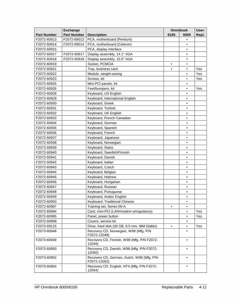
HP Omnibook 6000/6100 Replaceable Parts 4-11
Exchange Omnibook User-Part Number Part Number Description 6100 6000 Repl.F2072-60913 F2072-69013 PCA, motherboard (Pentium) •F2072-60914 F2072-69014 PCA, motherboard (Celeron) •F2072-60915 PCA, display interface •F2072-60917 F2072-60917 Display assembly, 14.1” XGA •F2072-60918 F2072-60918 Display assembly, 15.0” XGA •F2072-60919 Socket, PCMCIA • •F2072-60921 Tray, business card • • YesF2072-60922 Module, weight-saving • YesF2072-60923 Screws, kit • YesF2072-60925 Mini-PCI panels, kit •F2072-60926 Feet/bumpers, kit • YesF2072-60928 Keyboard, US English •F2072-60929 Keyboard, International English •F2072-60930 Keyboard, Greek •F2072-60931 Keyboard, Turkish •F2072-60932 Keyboard, UK English •F2072-60933 Keyboard, French Canadian •F2072-60934 Keyboard, German •F2072-60935 Keyboard, Spanish •F2072-60936 Keyboard, French •F2072-60937 Keyboard, Japanese •F2072-60938 Keyboard, Norwegian •F2072-60939 Keyboard, Swiss •F2072-60940 Keyboard, Swedish/Finnish •F2072-60941 Keyboard, Danish •F2072-60942 Keyboard, Italian •F2072-60943 Keyboard, Czech •F2072-60944 Keyboard, Belgian •F2072-60945 Keyboard, Hebrew •F2072-60946 Keyboard, Hungarian •F2072-60947 Keyboard, Russian •F2072-60948 Keyboard, Portuguese •F2072-60949 Keyboard, Arabic English •F2072-60950 Keyboard, Traditional Chinese •F2072-60987 Training set, Series 00-A • •F2072-60994 Card, mini-PCI (LAN/modem w/regulatory) • YesF2072-60995 Panel, power button • YesF2072-60999 Covers, service kit •F2072-69115 Drive, hard disk (30 GB, 9.5 mm, IBM Diablo) • • YesF2073-60948 Recovery CD, Norwegian, W98 (Mfg. P/N
F2072-12048)•
F2073-60949 Recovery CD, Finnish, W98 (Mfg. P/N F2072-12049)
•
F2073-60950 Recovery CD, Danish, W98 (Mfg. P/N F2072-12050)
•
F2073-60952 Recovery CD, German, Dutch, W98 (Mfg. P/NF2072-12052)
•
F2073-60954 Recovery CD, English, NT4 (Mfg. P/N F2072-12054)
•

4-12 Replaceable Parts HP Omnibook 6000/6100
Exchange Omnibook User-Part Number Part Number Description 6100 6000 Repl.F2073-60955 Recovery CD, German, NT4 (Mfg. P/N F2072-
12055)•
F2073-60956 Recovery CD, Spanish, NT4 (Mfg. P/N F2072-12056)
•
F2073-60957 Recovery CD, French, NT4 (Mfg. P/N F2072-12057)
•
F2073-60958 Recovery CD, Norwegian, NT4 (Mfg. P/N F2072-12058)
•
F2073-60959 Recovery CD, Finnish, NT4 (Mfg. P/N F2072-12059)
•
F2073-60960 Recovery CD, Danish, NT4 (Mfg. P/N F2072-12060)
•
F2073-60961 Recovery CD, Italian, NT4 (Mfg. P/N F2072-12061)
•
F2073-60963 Recovery CD, Japanese, NT4 (Mfg. P/N F2072-12063)
•
F2073-60965 Recovery CD, Swedish, W98 (Mfg. P/N F2072-12065)
•
F2073-60966 Recovery CD, Swedish, NT4 (Mfg. P/N F2072-12066)
•
F2073-60969 Recovery CD, Greek, W98 (Mfg. P/N F2072-12069)
•
F2140-60902 Recovery CD, Greek/English, W98 (Mfg. P/NF2140-12002)
•
F2140-60903 Recovery CD, Turkish, W98 (Mfg. P/N F2140-12003)
•
F2140-60906 Recovery CD, Japanese, W98 (Mfg. P/N F2140-12009)
•
F2140-60907 Recovery CD, Hebrew, W98 (Mfg. P/N F2140-12012)
•
F2140-60908 Recovery CD, Arabic, W98 (Mfg. P/N F2140-12013)
•
F2140-60909 Heatsink (thick, with fan) •F2140-60910 PCA, power supply •F2140-60911 PCA, display interface (XGA) •F2140-60912 PCA, display interface (SXGA+) •F2140-60914 Covers, user kit • YesF2140-60915 PCA, volume •F2140-60917 Recovery CD, Czech, W98 (Mfg. P/N F2140-
12017)•
F2140-60918 Recovery CD, Hungarian, W98 (Mfg. P/NF2140-12018)
•
F2140-60919 Recovery CD, Polish, W98 (Mfg. P/N F2140-12019)
•
F2140-60920 Recovery CD, Russian, W98 (Mfg. P/N F2140-12020)
•
F2140-60921 Recovery CD, Traditional Chinese, W98 (Mfg.P/N F2140-12021)
•
F2140-60923 Recovery CD, North American English, W98(Mfg. P/N F2140-12023)
•
F2140-60924 Recovery CD, International English, W98 (Mfg.P/N F2140-12024)
•

HP Omnibook 6000/6100 Replaceable Parts 4-13
Exchange Omnibook User-Part Number Part Number Description 6100 6000 Repl.F2140-60925 Recovery CD, German, W98 (Mfg. P/N F2140-
12025)•
F2140-60926 Recovery CD, Spanish, W98 (Mfg. P/N F2140-12026)
•
F2140-60927 Recovery CD, French, W98 (Mfg. P/N F2140-12027)
•
F2140-60929 Recovery CD, Swedish/English, W98 (Mfg. P/NF2140-12029)
•
F2140-60930 Recovery CD, Finnish/English, W98 (Mfg. P/NF2140-12030)
•
F2140-60931 Recovery CD, Danish/English, W98 (Mfg. P/NF2140-12031)
•
F2140-60932 Recovery CD, Italian, W98 (Mfg. P/N F2140-12032)
•
F2140-60933 Recovery CD, Dutch/English, W98 (Mfg. P/NF2140-12033)
•
F2140-60934 Recovery CD, North American English, W2K(Mfg. P/N F2140-12034)
•
F2140-60935 Recovery CD, International English, W2K (Mfg.P/N F2140-12035)
•
F2140-60936 Recovery CD, German, W2K (Mfg. P/N F2140-12036)
•
F2140-60937 Recovery CD, Spanish, W2K (Mfg. P/N F2140-12037)
•
F2140-60938 Recovery CD, French, W2K (Mfg. P/N F2140-12038)
•
F2140-60939 Recovery CD, Japanese, W2K (Mfg. P/N F2140-12039)
•
F2140-60940 Recovery CD, Norwegian, W2K (Mfg. P/NF2140-12040)
•
F2140-60941 Recovery CD, Swedish, W2K (Mfg. P/N F2140-12041)
•
F2140-60942 Recovery CD, Finnish, W2K (Mfg. P/N F2140-12042)
•
F2140-60943 Recovery CD, Danish, W2K (Mfg. P/N F2140-12043)
•
F2140-60944 Recovery CD, Italian, W2K (Mfg. P/N F2140-12044)
•
F2140-60948 Recovery CD, Norwegian/English, W98 (Mfg.P/N F2140-12048)
•
F2140-60949 F2140-69049 Display assembly, 15.0" SXGA+ •F2140-60950 Case, bottom •F2140-60951 Heatsink (thin, with fan) •F2140-60952 F2140-69052 PCA, motherboard (Pentium) •F2140-60953 PCA, power supply •F2140-60956 Recovery CD, Simplified Chinese, W98 (Mfg.
P/N F2140-12056)•
F2140-60957 Recovery CD, Dutch, W2K (Mfg. P/N F2140-12057)
•
F2140-60959 Recovery CD, Taiwanese Chinese, W98 (Mfg.P/N F2140-12059)
•
F2140-60960 Recovery CD, German/French W98 (Mfg. P/NF2140-12060)
•

4-14 Replaceable Parts HP Omnibook 6000/6100
Exchange Omnibook User-Part Number Part Number Description 6100 6000 Repl.F2140-60961 Cover, mini-PCI (Ambit card) • YesF2140-60962 Cover, mini-PCI (3Com card) • YesF2140-60964 F2140-69064 PCA, motherboard (Celeron) •F2196-80001 Card, PC (3Com Bluetooth) • YesF3257-60901 Keyboard, US English •F3257-60902 Keyboard, Belgian •F3257-60903 Keyboard, Czech •F3257-60904 Keyboard, Danish •F3257-60905 Keyboard, French •F3257-60906 Keyboard, French Canadian •F3257-60907 Keyboard, German •F3257-60908 Keyboard, Greek •F3257-60909 Keyboard, International English •F3257-60910 Keyboard, Italian •F3257-60911 Keyboard, Japanese •F3257-60912 Keyboard, Norwegian •F3257-60913 Keyboard, Portuguese •F3257-60914 Keyboard, Spanish •F3257-60915 Keyboard, Swedish/Finnish •F3257-60916 Keyboard, Swiss •F3257-60917 Keyboard, Turkish •F3257-60918 Keyboard, UK English •F3257-60919 Keyboard, Traditional Chinese •F3257-60920 Keyboard, Hebrew •F3257-60921 Keyboard, Icelandic •F3257-60922 Keyboard, Hungarian •F3257-60923 Keyboard, Russian •F3257-60924 Keyboard, Arabic/English •F3257-60925 Card, mini-PCI (802.11 wireless) • YesF3257-60927 Card, mini-PCI (HW modem) • YesF3257-60928 Case, top •F3257-60929 Panel, power button •F3257-60930 Heatsink (with fan) •F3257-60931 Tray, hard disk drive • YesF3257-60932 PCA, volume •F3257-60933 F3257-69033 PCA, motherboard (with Intel Speedstep) •F3257-60934 PCA, display interface •F3257-60935 Case, bottom •F3257-60936 Speaker assembly •F3257-60937 F3257-69037 Display assembly, 14.1" XGA •F3257-60939 F3257-69039 Display assembly, 15.0" SXGA+ •F3257-60940 Cover, mini-PCI (US Robotics) • YesF3257-60942 Cover, mini-PCI (no label) • YesF3257-60943 Cover, SDRAM (Actiontech) • YesF3257-60944 Cover, SDRAM (no label) • YesF3257-60947 Screws, kit • YesF3257-60948 Covers, service kit • YesF3257-60949 Mini-PCI panels, kit •
HP Omnibook 6000/6100 Replaceable Parts 4-15
Exchange Omnibook User-Part Number Part Number Description 6100 6000 Repl.F3257-60950 Feet/bumpers, kit • YesF3257-60951 Corner covers, kit • YesF3257-60952 Antennas, kit •F3257-60956 Pad, thermal • •F3257-60999 CD, Training •F3257-69100 Drive, hard disk (10 GB, 9.5 mm, IBM Diablo) • • YesF3257-69101 Drive, hard disk (10 GB, 9.5 mm, Toshiba) • • YesF3257-69102 Drive, hard disk (20 GB, 9.5 mm, Toshiba) • • YesF3257-69103 Drive, hard disk (30 GB, 9.5 mm, Toshiba) • • YesF3257-69104 Drive, hard disk (10 GB, 9.5 mm, Hitachi) • • YesF3257-69105 Drive, hard disk (20 GB, 9.5 mm, Hitachi) • • YesF3257-69106 Drive, hard disk (30 GB, 9.5 mm, Hitachi) • • Yes

HP Omnibook 6000/6100 Reference Information 5-1
5
Reference Information
This chapter includes the following reference information:
• Password removal policy.
• Display quality statement.
Password Removal Policy
If the user forgets the system password, the user calls Technical Support to determine the properremoval procedure. The user must provide proof of ownership, and the Omnibook must be operatedduring the procedure.
The password removal procedure is protected as HP Company Private information. There are arestricted number of locations that can perform password removal. It may not be disclosed ordistributed outside those locations.
Password removal is strictly controlled. Hewlett-Packard and authorized support providers mustensure with written evidence that the Omnibook being “cleansed” is actually in the possession of theunit’s actual and current owner. This requires a sales receipt showing the unit serial number andowner’s name, or a written statement from the owner attesting that he or she is the owner of the unit.The statement can be a fax copy of the document. The fact that the unit is in the hands of an HPrepresentative on behalf of the customer is not evidence of ownership. In addition, HP will not removethe password of a unit for any non-owner, even if it is requested by law enforcement agencies. If youreceive such a request, you should notify management and HP Corporate Legal immediately. (Theserequests may require a court order prior to our participation.)
Further, the entity removing the password must log the name, serial number and date of the removal,and file the written backup with the log. The log and backup are subject to standard record retentionprocess and review.
The final issue relating to removal of passwords is that HP cannot provide information to users thatwould assist them in improperly removing a password and opening a unit.

5-2 Reference Information HP Omnibook 6000/6100
Hewlett-Packard Display Quality Statement
TFT display manufacturing is a highly precise but imperfect technology, and manufacturers cannotproduce large displays that are cosmetically perfect. Most, if not all, TFT displays exhibit some levelof cosmetic imperfection. These cosmetic imperfections may be visible to the customer under varyingdisplay conditions, and can appear as bright, dim, or dark spots. This issue is common across allvendors supplying TFT displays in their products and is not specific to the HP Omnibook display.
HP Omnibook TFT displays meet or exceed all HP standards for cosmetic quality of TFT displays.HP does not warrant that the displays will be free of cosmetic imperfections. TFT displays can have asmall number of cosmetic imperfections and still conform to HP’s cosmetic quality specifications.
Here are some guidelines for determining what action to take on customers’ complaints of cosmeticimperfections in their TFT displays:
1. View the unit under the customer’s normal operating conditions.
This means that if the customer uses the unit predominately in DOS, in Windows, or in someother application or combination of applications, you should make the determination under thosesame applications. Self test is not a normal operating condition and is not a sufficient tool forinterpreting display quality.
2. Use the table below to determine whether the display should be considered for replacement.These are the only conditions in this guideline that may call for a replacement due to a defect inmaterial or workmanship based on the HP Limited Warranty Statement.
3. If a display is considered for replacement, make sure the customer understands that cosmeticvariations may also exist on the replacement display, and may require the customer to use a work-around to obscure the cosmetic imperfection.
4. Customers with cosmetic-based complaints that do not conform to the above conditions and testswill not normally be considered for display replacement. The HP-responsible person working withthe customer should identify work-arounds that are reasonable and appropriate for the individualcustomer. Customers who must have a more perfect display solution should consider switching toan Omnibook with a DSTN display.
We expect that over time the industry will continue to produce displays with fewer inherent cosmeticimperfections, and we will adjust our HP guidelines as these improvements are implemented.
HP Omnibook 6000/6100 Reference Information 5-3
Table 5-1. Omnibook 6000/6100 LCD Guidelines
Type of Imperfection Imperfections Not Allowed
Electrical Imperfections:
Bright dots (a)
Dark dots (a)
• 7 or more single bright dots.
• 7 or more single dark dots.
• 9 or more total (bright and dark combined) defective dots.
• Any occurrence of multiple defective dots within 15 mm.
Mechanical Imperfections:Discoloration
Polarizer bubbles, dents (b)
• Any polarizer bubble, discoloration, or dent that is visible from at least36 cm (14 in).
Definitions of imperfections:a Bright or dark dot: a subpixel (red, green, or blue dot) that is stuck on or off.b Polarizer dent or bubble: a light spot with a darker border that appears on a lighted display and does not
change size. (In contrast, a polarizer scratch is a light line that is visible on a darker background and doesnot change size.)
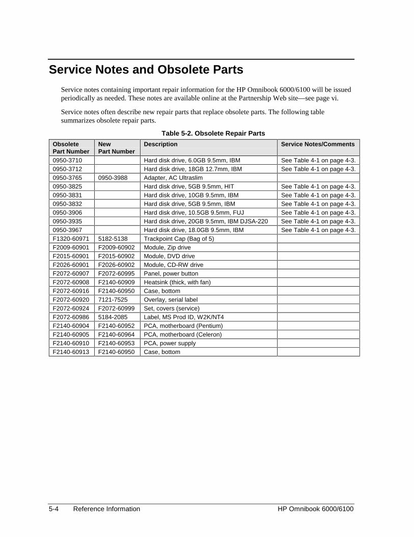
5-4 Reference Information HP Omnibook 6000/6100
Service Notes and Obsolete Parts
Service notes containing important repair information for the HP Omnibook 6000/6100 will be issuedperiodically as needed. These notes are available online at the Partnership Web site—see page vi.
Service notes often describe new repair parts that replace obsolete parts. The following tablesummarizes obsolete repair parts.
Table 5-2. Obsolete Repair Parts
ObsoletePart Number
NewPart Number
Description Service Notes/Comments
0950-3710 Hard disk drive, 6.0GB 9.5mm, IBM See Table 4-1 on page 4-3.0950-3712 Hard disk drive, 18GB 12.7mm, IBM See Table 4-1 on page 4-3.0950-3765 0950-3988 Adapter, AC Ultraslim0950-3825 Hard disk drive, 5GB 9.5mm, HIT See Table 4-1 on page 4-3.0950-3831 Hard disk drive, 10GB 9.5mm, IBM See Table 4-1 on page 4-3.0950-3832 Hard disk drive, 5GB 9.5mm, IBM See Table 4-1 on page 4-3.0950-3906 Hard disk drive, 10.5GB 9.5mm, FUJ See Table 4-1 on page 4-3.0950-3935 Hard disk drive, 20GB 9.5mm, IBM DJSA-220 See Table 4-1 on page 4-3.0950-3967 Hard disk drive, 18.0GB 9.5mm, IBM See Table 4-1 on page 4-3.F1320-60971 5182-5138 Trackpoint Cap (Bag of 5)F2009-60901 F2009-60902 Module, Zip driveF2015-60901 F2015-60902 Module, DVD driveF2026-60901 F2026-60902 Module, CD-RW driveF2072-60907 F2072-60995 Panel, power buttonF2072-60908 F2140-60909 Heatsink (thick, with fan)F2072-60916 F2140-60950 Case, bottomF2072-60920 7121-7525 Overlay, serial labelF2072-60924 F2072-60999 Set, covers (service)F2072-60986 5184-2085 Label, MS Prod ID, W2K/NT4F2140-60904 F2140-60952 PCA, motherboard (Pentium)F2140-60905 F2140-60964 PCA, motherboard (Celeron)F2140-60910 F2140-60953 PCA, power supplyF2140-60913 F2140-60950 Case, bottom


Part NumberF3257-90025 Printed in U.S.A. 6/01