Embed Size (px)
Citation preview

PD 340 Magnetic Flow Transmitter PD 210 Display Unit
Service Manual

PD 340 Magnetic Flow Transmitter PD 210 Display Unit Introduction
Thank you for purchasing an Alfa Laval product.
This manual has been provided to instruct you how to operate and service this product correctly and safely. Be sure to follow all directions and instructions; failure to do so could result in personal injury or equipment damage.
This manual should be considered part of this product and should remain with it at all times for reference. (If you sell it, please be sure to include this manual with it).
Warranty is provided as part of Alfa Laval’s commitment to our customers who operate and maintain their equipment as this manual dictates. Failure to do so may result in loss of warranty.
Where defects appear on the product during the warranty period. Alfa Laval will back the product and correct the problem. Should the equipment be modified or not kept in the manner prescribed within this manual, the warranty will become null and void.

PD 340 Magnetic Flow Transmitter PD 210 Display UnitTable of Contents
General Information.. .. .. .. .. .. .. .. .. .. .. .. .. .. .. .. .. .. .. .. .. .. .. .. .. .. .. .. .. .. .. .. .. .. .. .. .. .. .. .. .. .. .. .. .. .. .. .. .. 3
Installation . .. .. .. .. .. .. .. .. .. .. .. .. .. .. .. .. .. .. .. .. .. .. .. .. .. .. .. .. .. .. .. .. .. .. .. .. .. .. .. .. .. .. .. .. .. .. .. .. .. .. .. .. .. 6
PD 210 Display Unit . .. .. .. .. .. .. .. .. .. .. .. .. .. .. .. .. .. .. .. .. .. .. .. .. .. .. .. .. .. .. .. .. .. .. .. .. .. .. .. .. .. .. .. .. .. .. .. .. 9
Function Description . .. .. .. .. .. .. .. .. .. .. .. .. .. .. .. .. .. .. .. .. .. .. .. .. .. .. .. .. .. .. .. .. .. .. .. .. .. .. .. .. .. .. .. .. .. .. .. .11
Electrical Connections . .. .. .. .. .. .. .. .. .. .. .. .. .. .. .. .. .. .. .. .. .. .. .. .. .. .. .. .. .. .. .. .. .. .. .. .. .. .. .. .. .. .. .. .. .. .. .15
Variable Description.. .. .. .. .. .. .. .. .. .. .. .. .. .. .. .. .. .. .. .. .. .. .. .. .. .. .. .. .. .. .. .. .. .. .. .. .. .. .. .. .. .. .. .. .. .. .. .. .27
Configuration and Calibration .. .. .. .. .. .. .. .. .. .. .. .. .. .. .. .. .. .. .. .. .. .. .. .. .. .. .. .. .. .. .. .. .. .. .. .. .. .. .. .. .. .. .. .33
Error Detection .. .. .. .. .. .. .. .. .. .. .. .. .. .. .. .. .. .. .. .. .. .. .. .. .. .. .. .. .. .. .. .. .. .. .. .. .. .. .. .. .. .. .. .. .. .. .. .. .. .. .39
Technical Specifications . .. .. .. .. .. .. .. .. .. .. .. .. .. .. .. .. .. .. .. .. .. .. .. .. .. .. .. .. .. .. .. .. .. .. .. .. .. .. .. .. .. .. .. .. .. .42
Memory Types . .. .. .. .. .. .. .. .. .. .. .. .. .. .. .. .. .. .. .. .. .. .. .. .. .. .. .. .. .. .. .. .. .. .. .. .. .. .. .. .. .. .. .. .. .. .. .. .. .. .. .45
PD 340 Configuration Notes . .. .. .. .. .. .. .. .. .. .. .. .. .. .. .. .. .. .. .. .. .. .. .. .. .. .. .. .. .. .. .. .. .. .. .. .. .. .. .. .. .. .. .. .46
PD 340 Drawing/Parts List .. .. .. .. .. .. .. .. .. .. .. .. .. .. .. .. .. .. .. .. .. .. .. .. .. .. .. .. .. .. .. .. .. .. .. .. .. .. .. .. .. .. .. .. .48
Notes and Feedback .. .. .. .. .. .. .. .. .. .. .. .. .. .. .. .. .. .. .. .. .. .. .. .. .. .. .. .. .. .. .. .. .. .. .. .. .. .. .. .. .. .. .. .. .. .. .. .50

PD 340 Magnetic Flow Transmitter PD 210 Display Unit
Throughout each of Alfa Laval’s instruction manuals, certain safety signal words and symbols will appear. These are in the form of warnings, caution or note.
WARNING!: Indicated that special procedures MUST be followed to avoid severe personal injury.
CAUTION!: Indicates that special procedures MUST be followed to avoid damage to the equipment.
NOTE!: Denotes action or procedures to follow for optimum, safe use of product.
Follow Safety Directions
Read this manual thoroughly before working on equipment.
Leave all safety stickers on equipment and keep them maintained in legible condition. In the event that stickers become damaged or are missing, contact Alfa Laval for replacements.
Maintain equipment in good working condition.
Do Not Make Machine Modifications
Alfa Laval offers a full range of products to suite all your needs. Therefore, product modifications is never necessary.
Keep Maintenance Safe
Replace damaged or worn parts immediately. Never allow old product, debris, or any lubricants to build up on equipment. Never operate unless equipment is in proper working order.
Before attempting to service the machine, disconnect all power and compressed air. Allow machine to come to a complete stop. Never service a machine while it is operating. Keep all limbs away from moving equipment. Be sure that product pressure has been relieved before beginning maintenance.
Safety

PD 340 Magnetic Flow Transmitter PD 210 Display Unit
3
General Information
1.1 Introduction.
The PD 340 flow transmitter is a precision meter for the volumetric measurement of liquids which are electrically conductive.
The transmitter can be used in applications where a hygienic design is required. The rugged construction of the transmitter makes it suitable for installations where solid particles are in the liquids.
The PD 340 transmitter is equipped with a microprocessor which controls and supervises all of its functions.
Standard Design
The PD 340 flow transmitter consists of three parts; meterhead, electronic module, and terminal box.
The electronic module and the terminal box will fit all sizes of transmitter.
The Meterhead consists of a stainless metering pipe with clamp connections. Two magnetic coils are mounted external to the metering pipe. Two stainless electrodes are mounted inside the metering pipe.
The measuring section is designed so that changes in flow profile do not affect meter accuracy; hense the transmitter has a wide range of flow rates within its linear accuracy. Changes from laminar to turbulent flow do not affect the linear accuracy, and changing viscosity has no affect on meter accuracy. The calibration of the meterhead is carried out during manufacture using a computer controlled calibration facility.
The Electronic Module is micro-processor based and controls both the sequence of measurement and output signal transmission.
The use of micro-processor has enabled a compact design to be achieved while enabling many functions.
The electronic module is available in two versions, standard and extended.
The standard version has two pulse output signals and one logic input.
In the extended version, one of the pulse output signals can be changed into an analog current output signal, 4-20 mA.
In addition, it is possible to connect the extended version transmitter to a P-NET Fieldbus (data communication network) for central data collection or control.
The Terminal Box is completely separated from the electronic module. Connections can be therefore changed without disruption to the electronics. All terminals within the terminal box are clearlly marked with both number and function.
The box is also equipped with three core grips. (PG 11) Cable size is 3/16” ro 5/16” (4mm to 8mm).

PD 340 Magnetic Flow Transmitter PD 210 Display Unit
4
General Information
Product Features.
Sanitary design•
Maintenance-free, no moving parts•
Automatic Zero point correction•
Uni-directional or Bi-directional flow•
Volumetric measurement in m• 3 litres, U.S. gallons etc.
Pulse output to an electronic counter, 0-1000 pulses per second•
Pulse output to an electromechanical counter, 0-10 pulses per second•
Current output, 4-20mA (extended version)•
Batch control function•
Limit switch function•
Flow regulator function (PI controller)•
Practically no loss of pressure•
A display unit, PD 210, can be easily connected. The PD 210 unit can display accumulated • volume, setpoint for Batch control or PI regulator, flow rate, temperature, etc. It is also used for programming and has diagnostic capabilities.
Count stop/clear logic input function•
Temperature measurement using an external temperature detector (4 wire, 100 ohm RTD)•
Temperature compensated flow measurement•
Continuous Selftest, which can be monitored through the P-NET•
P-NET Fieldbus Communication, EN 50170, Volume 1•
EMC approved (89/336/ECC)•
Vibration approved (IEC 68-2-6 Test Fc)•
PD 340 Magnetic Flow Transmitter PD 210 Display Unit
5
General Information
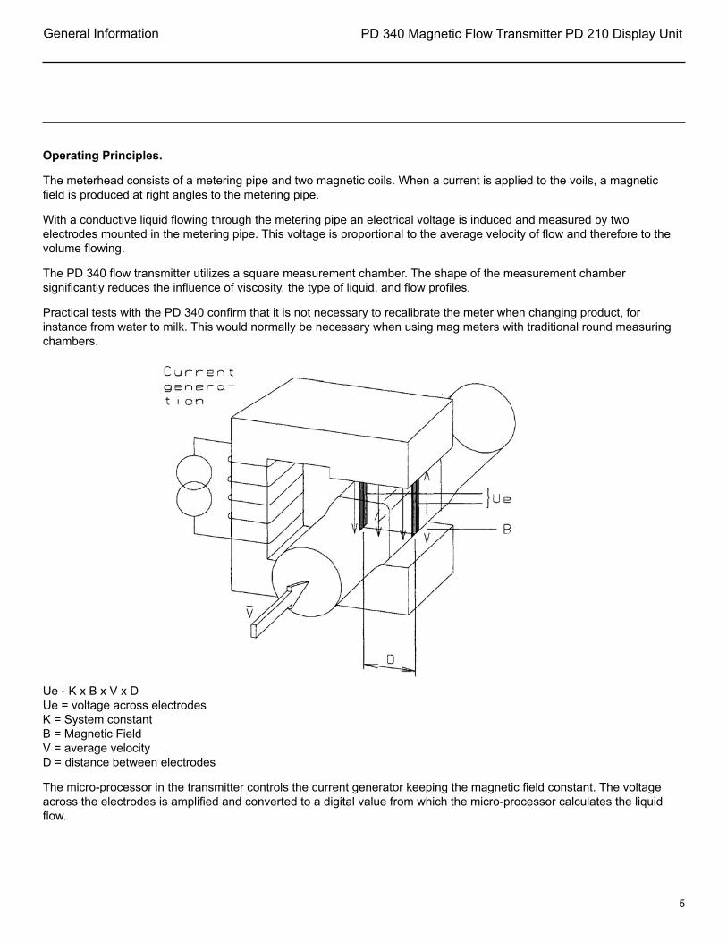
Operating Principles.
The meterhead consists of a metering pipe and two magnetic coils. When a current is applied to the voils, a magnetic field is produced at right angles to the metering pipe.
With a conductive liquid flowing through the metering pipe an electrical voltage is induced and measured by two electrodes mounted in the metering pipe. This voltage is proportional to the average velocity of flow and therefore to the volume flowing.
The PD 340 flow transmitter utilizes a square measurement chamber. The shape of the measurement chamber significantly reduces the influence of viscosity, the type of liquid, and flow profiles.
Practical tests with the PD 340 confirm that it is not necessary to recalibrate the meter when changing product, for instance from water to milk. This would normally be necessary when using mag meters with traditional round measuring chambers.
Ue - K x B x V x DUe = voltage across electrodesK = System constantB = Magnetic FieldV = average velocityD = distance between electrodes
The micro-processor in the transmitter controls the current generator keeping the magnetic field constant. The voltage across the electrodes is amplified and converted to a digital value from which the micro-processor calculates the liquid flow.

PD 340 Magnetic Flow Transmitter PD 210 Display Unit
6
Installation
Installation of Transmitter.
The transmitter should be installed within the pipework system such that the metering pipe is always filled with liquid, as the transmitter can register flow, even if the meter is empty.
As the transmitter sees air in the liquid as a volume, the volume of air in the liquid must be reduced to a minimum, and the transmitter should be located in the pipework system, at the point of maximum pressure. Here the volume of the air is at a minimum of the influence of air on the measurement will also be at a minimum.
If heavy vibrations occur in the pipework e.g. Caused by resonance from pumps, or a pulsating pressure in connection with e.g. a homogenizer or a positive displacement pump, a vibration damping is required, or the transmitter must be mounted somewhere else with less variation of pressure.
If the liquid contains air, an air eliminator should be mounted before the flow transmitter.
The transmitter can be mounted both horizontally and vertically. No air must be trapped in the meter head. The positive flow direction is indicated by an arrow on the meterhead.
If mounted horizontally, make sure the electrodes are on either side as shown, not on top and bottom.
To create the best conditions for precise metering, a straight pipe run of least three times the pipework diameter should be mounted upstream and downstream of the transmitter.
When selecting the location of the transmitter it must be ensured that the ambient temperature is within the specified limits. Finally, the transmitter should be installed such that the electronic module and the terminal box can be fitted and dismantled in place.
NOTE: The clamp connection must be loosened completely before the transmitter is rotated. Otherwise the meterhead will be seriously damaged and require replacement.
CAUTION!
Precautions must be taken to ensure that the electronic module, the meterhead, the terminal box are not exposed to moisture when the transmitter is dismantled. To prevent moisture, the cables must be mounted correctly in the glands. The electronic module and the terminal box must be carefully mounted with all screws tightened.
The flow transmitter supply should always be connected, as heat developed in the electronic module prevents condensation which could damage the transmitter. As soon as possible after mounting, the transmitter should be powered up.

PD 340 Magnetic Flow Transmitter PD 210 Display Unit
7
Installation
Selecting the right meter size.
The flow transmitter has a very large measuring range. The optimal flow measurement is obtained when the flow rate is close to, but below the maximum flow rate for the flow transmitter. Flow rates greater than the maximum specified flow rate + 10% are not measured and therefore not registered. This means that the flow rate must never exceed the maximum specified value.
Practical examples from different installations indicate that the flow rate varies. Therefore it is recommended that the calculated maximum flow rate should not exceed 90% of the specified maximum flow rate for the selected flow transmitter. Exceptions may be made if the flow rate is well known and very stable.
If the operational flow rate for the flow transmitter is below 30% of the maximum flow rate for the flow transmitter, it is recommended to select a smaller dimension, if existing.
Flow measurement down to 5% of maximum flow rate for the flow transmitter, or even lower is also possible, but a reduced accuracy (+/1 1%).
The size of the meterhead should be selected according to the maximum flow rate. This maximum flow rate must be the absolute maximum flow rate during operation, cleaning, startup etc. The smallest possible transmitter is the chosen for that maximum flow rate. This will ensure optimum measurement accuracy. If the metering section is smaller than the pipework in the installation, reducers should be used.
A flow transmitter should not be installed in a piping system where the pipe lines are smaller than the connections on the meter.
If two products are mixed before measuring, the mixed product must be homogenous liquid before entering the flow transmitter to ensure maximum accuracy.
CAUTION: The max. flow rate for the flow transmitter must NEVER be exceeded. Otherwise the meterhead may be damaged.

PD 340 Magnetic Flow Transmitter PD 210 Display Unit
8
Dimensions
Capacities
Size Capacity Net
max GPM (lbs)1" (C25) 35 111½" (C38) 88 112" (C51) 176 112½" (C63) 352 113" (C76) 528 11
NOTE:
The maximum flow rate for the flow transmitter must never be exceeded. Exceeding the maximum flow rate will cause damage to the meter head and will void the warranty.
Installation

PD 340 Magnetic Flow Transmitter PD 210 Display Unit
9
PD 210 Display Unit
PD 210 Display Unit.
The PD 210 display unit is connected direclty to the transmitter. With this unit you can perform different functions.
Display of data from the transmitter, e.g. flow, volume, or temperature•
Changing the data in the transmitter, e.g. contents of volume registered or setpoint registered.•
Configuration and calibration, e.g. setting of the size of the meterhead or the function of the • output signals.
Readout and reset of an internal error code.•
Single setpoint batch control.•
The display unit is connect to the flow transmitter with a two wire cable, up to a length of 325 ft. The display unit is supplied with power via this cable. It also carries the exchange of data between the flow transmitter and the display unit. It can be mounted on the terminal box or on a control panel face.
Display of registers.
The contents of 8 different registers in the transmitter can be displayed on the unit. A touch on one of the 8 buttons under the display selects whichever register you want to read. The display indication is automatically updated about once per sec.
Reg. No. Name Function1 FLOW Liquid flow, e.g. in GPM, lbs/hr2 T.C. FLOW Temperature compensated flow3 TEMP. Temperature in °C or °F4 “blank” Available register5 VOL. 1 Volume, result or totalization, e.g. in Gal., lbs (grand total)6 VOL. 2 Volume for comparing with setpoint, e.g. in Gal, lbs. (Batch total)7 SETP. Setpoint, e.g. in GAL, lbs.8 “blank” Instant Flow

PD 340 Magnetic Flow Transmitter PD 210 Display Unit
10
PD 210 Display Unit
Changing the register.
If a change in the contents of a register is required, the register must first be displayed. Then the desired contents are entered, followed by the = button. This gives a blank display for approx. 1 sec., and then the new contents are displayed in the normal way.
Configuration and calibration using the PD 210.
The flow transmitter contains 8 configuration registers. See page 33 also for detailed explanation and purpose of these registers. If you want to display the contents of a configuration register, touch the E button, which will turn the display blank. Then press a numeral key between 1 and 8 to choose a configuration register. The number of the configuration register appears in the first digit of the display, and the contents of the register in the rest of the display. Changing the contents of a register is performed by keying in the new contents, and pressing the = button.
NOTE: The program enable switch must be on to change configuration registers.
Error readout.
The user is informed by an “A” for ALARM appearing in the first digit of the display. By pressing the “TEST” button the display will show an error code of two digits, indicating the type of error. The test system ensures that the alarm will not be cancelled before the error code has been displayed by pressing the “TEST” button, even though the error may be disappeared. By pressing the “TEST” button once again, the display will show “0” if the flow transmitter is error free now. The error code on the display is only updated by re-pressing the “TEST” button. A complete list of error codes are given on page 29.
Construction.
The display unit consists of a LCD-display, a keyboard and electronics for exchange of data with the flow transmitter, and control of the display and the keypad.
The unit is built into a box of NORYL PPO, sealed to IP 65 (NEMA 4). The dimension of the box are L x H x D = 5.7" x 2.8" x 0.3".
The electronics are based on a micro-processor which controls the LCD-display, scans the keypad, and controls the communication with the flow transmitter.
Dimensional drawing for PD 210.
NOTE: Please observe that the M3 mounting screw holes are only 4 mm. deep.
CAUTION!
Do NOT screw down beyond this length. This may damage the unit.

PD 340 Magnetic Flow Transmitter PD 210 Display Unit
11
Function Description
Function description.
The flow transmitter holds a number of internal functions and connections for external signals. The function may be selected by keying in a set of configuration parameters. Calibration parameters may also be set (E1). The data my be entered via a PD 210 Display unit or by using the P-NET Fieldbus interface.
The flow transmitter may be scaled or operate in any volumetric units, Litre, M3, Gallon, etc. the flow rate may be selected to be displayed as volume unit/hour or /minute.
Flow measurement.
The flow rate may be filtered to stabilize the readout of an unstable flow (E8).
Flow rates below 0.2% may be ignored. This may be useful to avoid totalizing the volume during long periods with no flow.
The flow is measured in both directions. Flow following the arrow on the meter head will be indicated as positive flow. Operationally the negative flow may be ignored and set to zero (E8).
To compensate for the expansion of the liquid, the flow transmitter may be configured to indicate a flow as if the liquid temperature was at 40°F (page 30).
Test mode.
The flow transmitter may be set in test mode. During installation and service, the test mode may be used to simulate that liquid is flowing in the pipe system. All output signals, pulse signals as well as current signal will act as if the liquid flow was present. This way, all internal functions, external signals and cable connections may be checked (E7).
Volume counter.
The flow transmitter utilizes two independent totalizers, Volume 1 and Volume 2, which indicate the measured volume since they were cleared. Each volume counter may independently be cleared or preset to a specific value. They may also be set to a maximum value by setting the resolution (E6).
Automatic Functions.
A number of automatic functions are selectable in the flow transmitter. Only one of the functions can be selected for each group (E7).
Batch control.
The flow transmitter has a built-in batch control function, and can therefore easily be used to control the metering of a specified volume. The requested volume is keyed into a setpoint register. A digital input on the flow transmitter may be used to start the batch control. A digital output, Output 2, opens a metering value or starts a pump. When the setpoint volume is reached, the output is switched off and the valve is closed or the pump stops. The Volume 2 counter shows the batched volume (page 17).
PD 340 Magnetic Flow Transmitter PD 210 Display Unit
12
Function Description
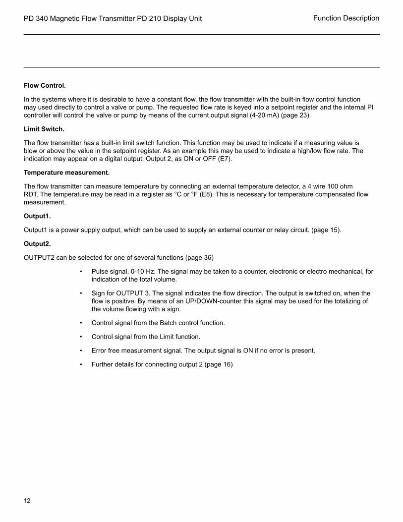
Flow Control.
In the systems where it is desirable to have a constant flow, the flow transmitter with the built-in flow control function may used directly to control a valve or pump. The requested flow rate is keyed into a setpoint register and the internal PI controller will control the valve or pump by means of the current output signal (4-20 mA) (page 23).
Limit Switch.
The flow transmitter has a built-in limit switch function. This function may be used to indicate if a measuring value is blow or above the value in the setpoint register. As an example this may be used to indicate a high/low flow rate. The indication may appear on a digital output, Output 2, as ON or OFF (E7).
Temperature measurement.
The flow transmitter can measure temperature by connecting an external temperature detector, a 4 wire 100 ohm RDT. The temperature may be read in a register as °C or °F (E8). This is necessary for temperature compensated flow measurement.
Output1.
Output1 is a power supply output, which can be used to supply an external counter or relay circuit. (page 15).
Output2.
OUTPUT2 can be selected for one of several functions (page 36)
Pulse signal, 0-10 Hz. The signal may be taken to a counter, electronic or electro mechanical, for • indication of the total volume.
Sign for OUTPUT 3. The signal indicates the flow direction. The output is switched on, when the • flow is positive. By means of an UP/DOWN-counter this signal may be used for the totalizing of the volume flowing with a sign.
Control signal from the Batch control function.•
Control signal from the Limit function.•
Error free measurement signal. The output signal is ON if no error is present.•
Further details for connecting output 2 (page 16)•

PD 340 Magnetic Flow Transmitter PD 210 Display Unit
13
Function Description
Output 3
Output3 may be used as a digital signal output or as an analog 4-20 my current output (extended version only). When used as a digital signal, it may be used as a fast pulse signal (0 - 1000 Hz) for external counter circuits (see scaling example on page 34) or it may be controlled directly via PNET fielders, Further details for connecting Output3 (pages 19-24).
Input.
The transmitter has a logic input, INPUT 1 , which can be selected for one of several functions • page 37)
Stop counters. The signal may come from an air detector or product probe, and is then used to • make the transmitter stop counting, when there is air in the liquid or no product Flow.
Clear Volumed counter, The input can be used in batch control, to start the Batch function and • clear the batch volume counter.
Manual/Automatic mode for PI controller. The input can be used to set the operation mode for the • Pl controller (E3).
P-NET interface.
The extended version of the flow transmitter utilizes a P-NET fielders communication interface. This enables the flow transmitter to be connected directly to P-NET. P-NET is a fielders network designed for process control and data-collection. P-NET is a RS-485 Serial interface used for communicating with P-NET interface modules with a transmission speed of 76,800 baud. Through the P-NET it is possible to display and change all the internal data within the flow transmitter,
PD 340 Magnetic Flow Transmitter PD 210 Display Unit
14
Function Description
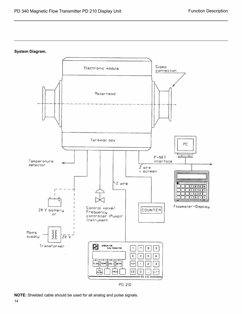
System Diagram.
NOTE: Shielded cable should be used for all analog and pulse signals.
PD 340 Magnetic Flow Transmitter PD 210 Display Unit
15
Electrical Connections
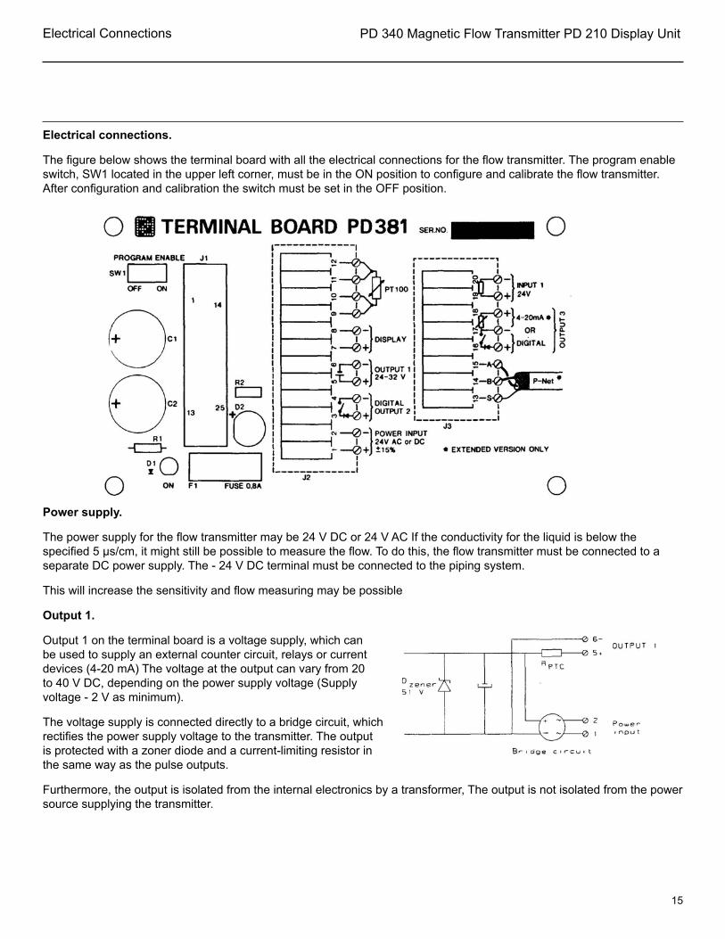
Electrical connections.
The figure below shows the terminal board with all the electrical connections for the flow transmitter. The program enable switch, SW1 located in the upper left corner, must be in the ON position to configure and calibrate the flow transmitter. After configuration and calibration the switch must be set in the OFF position.
Power supply.
The power supply for the flow transmitter may be 24 V DC or 24 V AC If the conductivity for the liquid is below the specified 5 µs/cm, it might still be possible to measure the flow. To do this, the flow transmitter must be connected to a separate DC power supply. The - 24 V DC terminal must be connected to the piping system.
This will increase the sensitivity and flow measuring may be possible
Output 1.
Output 1 on the terminal board is a voltage supply, which can be used to supply an external counter circuit, relays or current devices (4-20 mA) The voltage at the output can vary from 20 to 40 V DC, depending on the power supply voltage (Supply voltage - 2 V as minimum).
The voltage supply is connected directly to a bridge circuit, which rectifies the power supply voltage to the transmitter. The output is protected with a zoner diode and a current-limiting resistor in the same way as the pulse outputs.
Furthermore, the output is isolated from the internal electronics by a transformer, The output is not isolated from the power source supplying the transmitter.

PD 340 Magnetic Flow Transmitter PD 210 Display Unit
16
Electrical Connections
Digital output signals.
The flow transmitter has two digital output signals, OUTPUT 2 and 3. Voltage supplies are required for output signals.
The outputs are isolated from the other pad of the electronics by optocouplers. Furthermore, the outputs are protected against overload by a zener diode and a current-limiting resistance, Rptc is about 25 ohm at normal load (max 1 00 mA). At overload, the Rprc Will rise rapidly thus limiting the current to about 16 mA.
If an output has been overloaded, the current must be completely switched off for some seconds, by switching off the power supply to the flow transmitter, before the output can be normally loaded again.
A voltage drop of up to 1 .0 V may occur when the output is switched ON. This should be noted when connecting to low voltage eternal equipment.
In case of wrong polarization of the connection, the signal acts as a constant ON signal.
OUTPUT2
The pulse output signal from OUTPUT 2 has a pulse width of 40 ms. The frequency is continuously variable from 0-1 0 Hz.
Pulse signal Output 2
Example of electrical connection of electro-mechanical counters
Counter specification:
Supply voltage: 20-40 V DC
Power consumption: Max. 2.5 W
Counting frequency: Min, 1 O Hz
ON-time: Typ. 40 ms
OFF-time: Min. 60 ms
If output 2 is to be connected to an electronic counter or PLC, it may be necessary to equip the count pulse input on the counter/PLC with a pull-up resistance if one is not provided. Use terminals 3 and 4 (output 2) and wire to counter/PLC in the same manner as shown for output 3 (see page 19).
PD 340 Magnetic Flow Transmitter PD 210 Display Unit
17
Electrical Connections
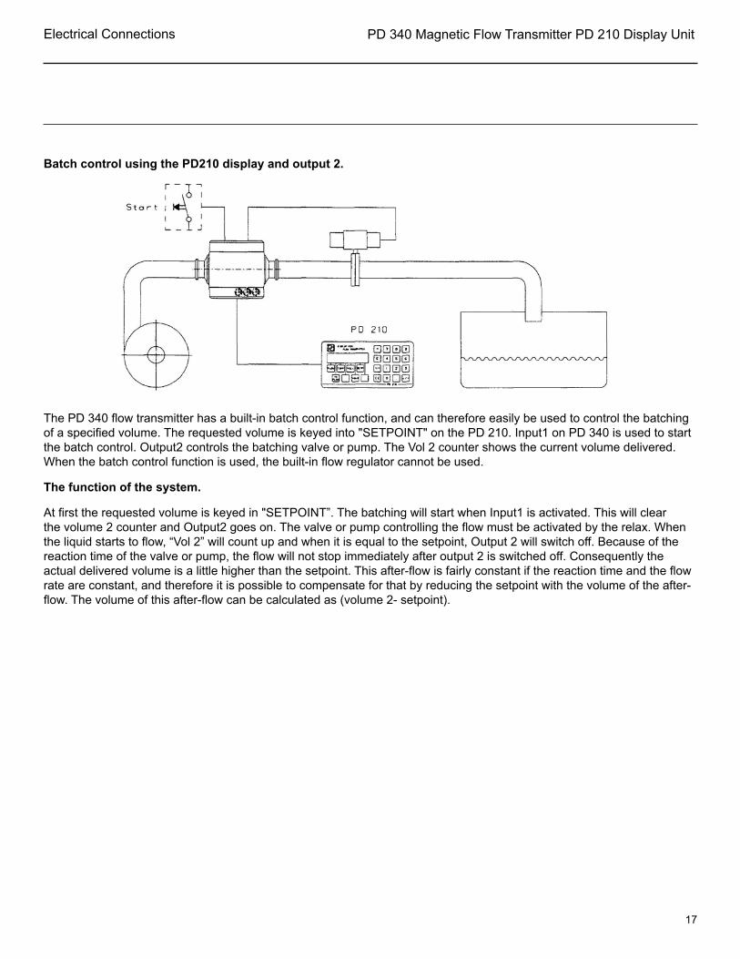
Batch control using the PD210 display and output 2.
The PD 340 flow transmitter has a built-in batch control function, and can therefore easily be used to control the batching of a specified volume. The requested volume is keyed into "SETPOINT" on the PD 210. Input1 on PD 340 is used to start the batch control. Output2 controls the batching valve or pump. The Vol 2 counter shows the current volume delivered. When the batch control function is used, the built-in flow regulator cannot be used.
The function of the system.
At first the requested volume is keyed in "SETPOINT”. The batching will start when Input1 is activated. This will clear the volume 2 counter and Output2 goes on. The valve or pump controlling the flow must be activated by the relax. When the liquid starts to flow, “Vol 2” will count up and when it is equal to the setpoint, Output 2 will switch off. Because of the reaction time of the valve or pump, the flow will not stop immediately after output 2 is switched off. Consequently the actual delivered volume is a little higher than the setpoint. This after-flow is fairly constant if the reaction time and the flow rate are constant, and therefore it is possible to compensate for that by reducing the setpoint with the volume of the after-flow. The volume of this after-flow can be calculated as (volume 2- setpoint).

PD 340 Magnetic Flow Transmitter PD 210 Display Unit
18
Electrical Connections
Programming the batch control.
To obtain the requested functions the PD 340 must be programmed as shown below, When programming the flow transmitter the Program Enable Switch on the terminal board must be in position ON. Digits marked with * are not used for the batch control function, but should be programmed according to meter size and other working conditions.
E1: ****** E5: ****** E2: ****** E6: ****** E3: 000000 E7: **2106 E4: ****** E8: *0*4**
When programming is done, the Program Enable Switch should be put back to position OFF. The value in setpoint register before the program enable switch was switched off will be used as a power-up value after a power-cut.
Batch Control Wiring.

PD 340 Magnetic Flow Transmitter PD 210 Display Unit
19
Electrical Connections
Output3
The current output extension board for the flow transmitter can generate two different output signals at output3, pulse output signal or analog current output signal. Voltage supplies are required for both types of signals.
The pulse output signal from OUTPUT 3 is symmetrical (50 - 50 % duty cycle), and the frequency is continuously variable from 0-1000 Hz.
Electronic counters and PLC’S are normally connected to the pulse output, Output 3.
The pulse output in the transmitter consists of a voltage free electronic switch contact. Therefore, it is necessary to equip the count pulse input on the counter/PLC with a pull-up resistance, if the counter/PLC has no internal pull-up.

PD 340 Magnetic Flow Transmitter PD 210 Display Unit
20
Electrical Connections
PD 340 Magnetic Flow Transmitter PD 210 Display Unit
21
Electrical Connections
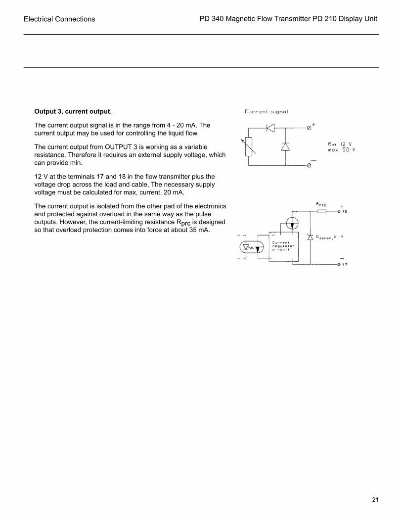
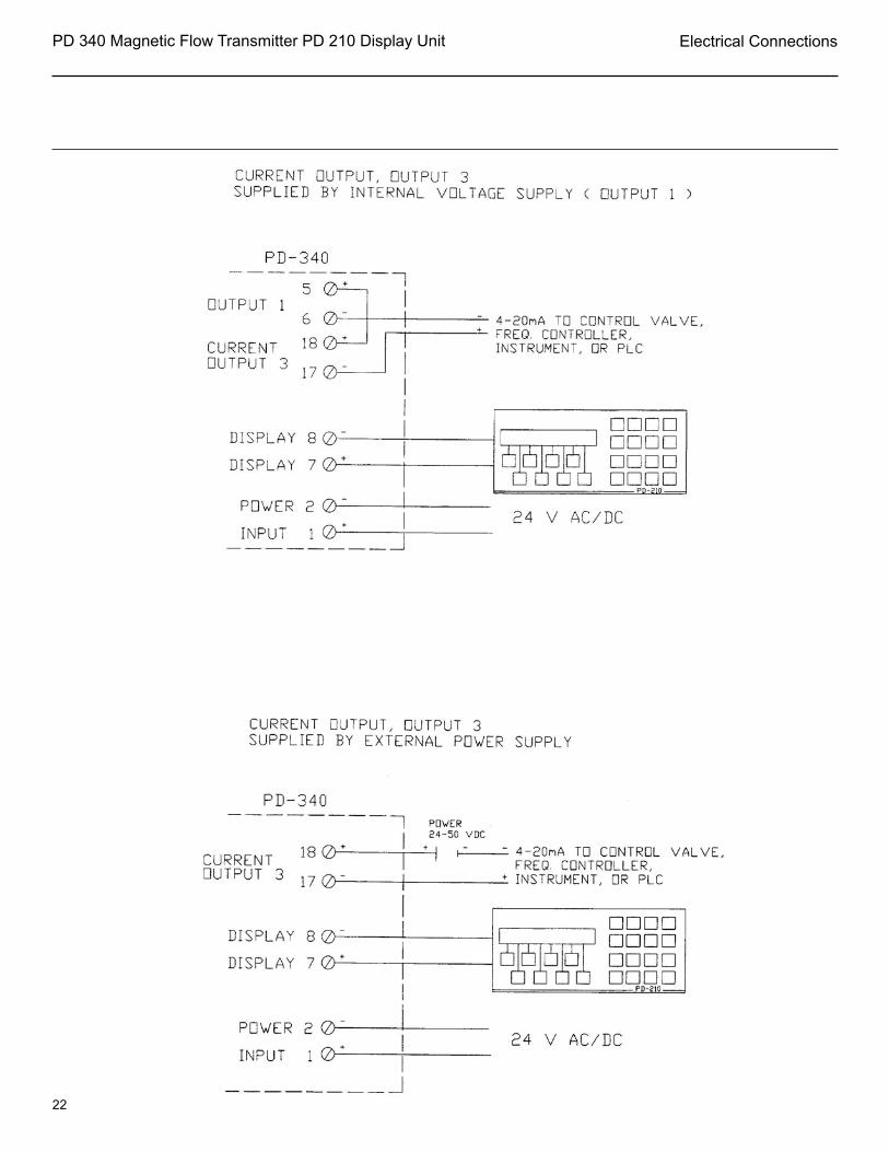
Output 3, current output.
The current output signal is in the range from 4 - 20 mA. The current output may be used for controlling the liquid flow.
The current output from OUTPUT 3 is working as a variable resistance. Therefore it requires an external supply voltage, which can provide min.
12 V at the terminals 17 and 18 in the flow transmitter plus the voltage drop across the load and cable, The necessary supply voltage must be calculated for max, current, 20 mA.
The current output is isolated from the other pad of the electronics and protected against overload in the same way as the pulse outputs. However, the current-limiting resistance Rprc is designed so that overload protection comes into force at about 35 mA.
PD 340 Magnetic Flow Transmitter PD 210 Display Unit
22
Electrical Connections

PD 340 Magnetic Flow Transmitter PD 210 Display Unit
23
Flow control using the PD210 DISPLAY and OUTPUT 3.
A centrifugal pump, a PD 340 flow transmitter and a modulating valve with an l/P converter will form an accurate FLOW CONTROL SYSTEM The requested flow rate is keyed into SETPOINT on the connected PD 210 display. The output value can be read in % by pressing the untitled key of the left of VOL. 2. If the regulator is in MANUAL, the operator can key the requested output position into the same register.
Programming the Flow Control.
To enable the PI REGULATOR function in the PD 340, the flow transmitter should be programmed in the following way. The * indicates that these digits are not in use for this function but should be programmed according to the meter size and other working conditions of the flow transmitter The program enable switch must be in position ON during programming.
E1: ****** E5: P-band E2: --Ti-- E6: ****** E3: 0000AB E7: 18**0* E4: ****** E8: ******
Electrical Connections
PD 340 Magnetic Flow Transmitter PD 210 Display Unit
24
Electrical Connections
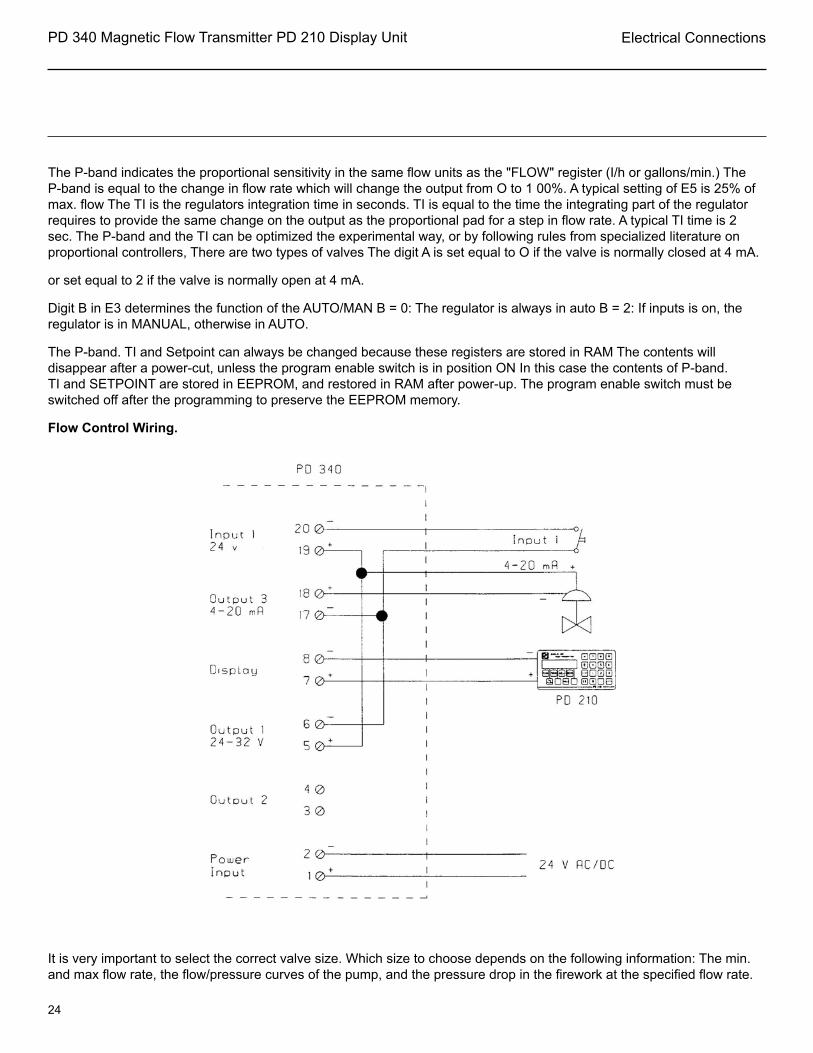
The P-band indicates the proportional sensitivity in the same flow units as the "FLOW" register (I/h or gallons/min.) The P-band is equal to the change in flow rate which will change the output from O to 1 00%. A typical setting of E5 is 25% of max. flow The TI is the regulators integration time in seconds. TI is equal to the time the integrating part of the regulator requires to provide the same change on the output as the proportional pad for a step in flow rate. A typical TI time is 2 sec. The P-band and the TI can be optimized the experimental way, or by following rules from specialized literature on proportional controllers, There are two types of valves The digit A is set equal to O if the valve is normally closed at 4 mA.
or set equal to 2 if the valve is normally open at 4 mA.
Digit B in E3 determines the function of the AUTO/MAN B = 0: The regulator is always in auto B = 2: If inputs is on, the regulator is in MANUAL, otherwise in AUTO.
The P-band. TI and Setpoint can always be changed because these registers are stored in RAM The contents will disappear after a power-cut, unless the program enable switch is in position ON In this case the contents of P-band. TI and SETPOINT are stored in EEPROM, and restored in RAM after power-up. The program enable switch must be switched off after the programming to preserve the EEPROM memory.
Flow Control Wiring.
It is very important to select the correct valve size. Which size to choose depends on the following information: The min. and max flow rate, the flow/pressure curves of the pump, and the pressure drop in the firework at the specified flow rate.

PD 340 Magnetic Flow Transmitter PD 210 Display Unit
25
Electrical Connections
INPUT signal.
The input signal is galvanically isolated. To activate the input, a voltage of minimum 1 8 V must be connected to the terminals with the right polarization. This voltage may be supplied from either the internal voltage supply or an external power supply.
Temperature signal.
A standard 4 wire RTD temperature sensor may be connected to the flow transmitter The temperature sensor must be connected with a 4-wire cable all the way from the sensor to the terminal box This must be done to avoid errors influenced by the cable, junctions and connections.
NOTE: lf a temperature sensor is not used, the terminals 9-10-11-12 must be connected together to avoid errors in the flow measurement.

PD 340 Magnetic Flow Transmitter PD 210 Display Unit
26
Electrical Connections
Connecting the display unit, PD 210.
The display unit is connected to the flow transmitter with a two wire twisted cable, up to a length of 325 ft. The display unit is supplied with power via this cable. It also carries the exchange of data between the flow transmitter and the display unit.
The communication speed between the flow transmitter and the PD 210 display unit is 300 bit/ sec, resulting in a new data readout approx. each second.
To improve the electrical noise immunity at a long distance, a shielded cable is recommended.
The shield must then be connected to terminal 8 at the terminal box and not connected at the display unit.
P-NET connections.
The P-NET is a multi drop bus, which is connected in a physical ring (series). Up to 125 units can be connected to the bus, where a unit may be a PD 340 flow transmitter, a flowmeter display or another P-NET interface module. The P-NET interface is galvanically isolated. The bus cable is a twisted pair with shield, and the shield is used as a potential equalizer between the driver/receiver circuits in the nodes connected to the bus.
A P-NET unit is connected to the bus by means of 3 terminal-connections, the A terminal, the B terminal and the S terminal.
The connection from one unit to the next unit is performed by connecting A to A, B to B and S to S. The S terminal must not be connected to ground. lf the length of the cable is more than 325ft, the bus cable will have to be connected from field device to field device, forming a physical ring.
Electrical specification for P-NET:
Bus structure: A physical ring without termination.
Medium: Shielded twisted pair cable 24 AWG minimum conductor with characteristic impedance of 100-120 ohm.
For example TWINAX IBM part No. 7362211 with 105+/-5 ohm, 51 pF/ m .
Bus length: Max 3935A (EIA RS 485).
PD 340 Magnetic Flow Transmitter PD 210 Display Unit
27
Variable Description
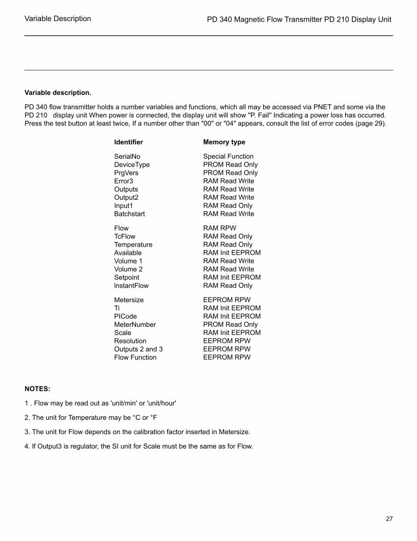
Variable description.
PD 340 flow transmitter holds a number variables and functions, which all may be accessed via PNET and some via the PD 210 display unit When power is connected, the display unit will show ''P. Fail'' Indicating a power loss has occurred. Press the test button at least twice, If a number other than "00" or "04" appears, consult the list of error codes (page 29).
Identifier
SerialNoDeviceTypePrgVersError3OutputsOutput2Input1 Batchstart
FlowTcFlowTemperatureAvailableVolume 1Volume 2SetpointlnstantFlow
MetersizeTiPICode MeterNumberScaleResolutionOutputs 2 and 3Flow Function
Memory type
Special FunctionPROM Read OnlyPROM Read OnlyRAM Read WriteRAM Read WriteRAM Read WriteRAM Read OnlyRAM Read Write
RAM RPWRAM Read OnlyRAM Read OnlyRAM Init EEPROMRAM Read WriteRAM Read WriteRAM Init EEPROMRAM Read Only
EEPROM RPWRAM Init EEPROMRAM Init EEPROMPROM Read OnlyRAM Init EEPROMEEPROM RPWEEPROM RPWEEPROM RPW
NOTES:
1 . Flow may be read out as 'unit/min' or 'unit/hour'
2. The unit for Temperature may be °C or °F
3. The unit for Flow depends on the calibration factor inserted in Metersize.
4. lf Output3 is regulator, the SI unit for Scale must be the same as for Flow.

PD 340 Magnetic Flow Transmitter PD 210 Display Unit
28
Variable Description
PD 210 display key: TEST
The flow transmitter is equipped with a comprehensive test system which is able to disclose faults, arising from improper use of the transmitter or faults arising from the transmitter during use. When the test system registers a fault, an error code is generated and saved in this register.
lf more than one error occurs at the same time, only the highest error code will be saved The error code will be saved until it has been read out, By reading out the error code twice, one can see if the error has disappeared again. The error codes F0 through F4 can only be read out via PNET. The PD 210 display unit will show the text ''P.FAIL'' after resetting the transmitter.

PD 340 Magnetic Flow Transmitter PD 210 Display Unit
29
Variable Description
ERROR CODE
F4F3F2F1F08382818076756463625452
444342242308070504030201
FAULT TYPE
RESET due to internal error RESET due to internal error RESET due to $FF in error code via P-NET RESET due to internal error RESET due to power cut Error in program storage (PROM) Error in program execution - watchdogError in data storage (PROM) Error an program executionError in EEPROM-storageError in RAM-storage or EEPROM-storageImproper connection of temperature detector Improper connection of temperature detector Temperature detector disconnected Magnetic coil in meter heat disconnected Magnetic coil in meter head short-circuited (may also occur from empty metering pipe in C marked meters) Shunt in meter head defective Shunt in meter head defective Shunt in meter heat defectiveTemperature >> maxTemperature > 130°/ 266°F Overrun, volume counter 2 Overrun, volume counter 1 Input active Flow >> max/metering pipe emptyFlow > maxOverflow, output 2Overflow, Output 3

PD 340 Magnetic Flow Transmitter PD 210 Display Unit
30
Variable Description
Process variables.
PD 210 display key: FLOW
This register shows the current flow rate for the liquid in the flow transmitter. The flow rate is an averaged value, where the time constant for the digital filter and the time unit may be selected in the E8 register. The time constant for the filter can be chosen in the interval from approx. 0. 15 sec.
To approx. 10 sec, Reverse flow (relative to the arrow on the meter head) can be set to 0, as well as flow rates smaller than 0.2% of max. flow can be set to 0.
PD 210 display key: T.C.FLOW
In addition to the normal flow measurement, the flow transmitter also measures a temperature, which may be used to calculate a temperature compensated flow.
The calculation of the temperature compensated flow is performed to compensate for the expansion of the liquid as a function of the liquid temperature The temperature compensated flow is automatically calculated by the flow transmitter by multiplying the flow rate by a temperature dependant correction factor, K.
The temperature compensated flow, TC flow, may be read directly in this register, The relation between temperature and K is stored in the flow transmitter and is shown below Implementing an automatic calculation of TC flow in the entire temperature range requires a 4 wire RTD temperature sensor to be connected at the terminals 9, 10, 11 and 12.

PD 340 Magnetic Flow Transmitter PD 210 Display Unit
31
Variable Description
Temperature compensation may be implemented for liquids at fixed temperature without using a 4 wire RTD. This is showed in the following examples The liquid is at a fixed temperature of 75°C during production, no RTD sensor is connected, but temperature compensated flow is wanted for the volume counters.
The value for the correction factor K is read from the diagram, 0.975. This value is now multiplied with the value from PD 210 E1, Metersize, and stored back in Metersize. The E7 register, digit 4 must be 1 to select Flow as data for volume counters.
NOTE: Using this kind of temperature compensation will only give the correct result when the liquid is at the fixed temperature.
PD 210 display key: TEMP
This register shows the temperature, calculated relative to the RTD connected to the flow transmitter.
lf the four terminals for the temperature detector are short-circuited, the calculated temperature will be approx. -245°C, equal to -409°F. The calculation unit for temperature is selected in the E8 register.
PD 340 Magnetic Flow Transmitter PD 210 Display Unit
32
Variable Description
PD 210 display key; "blank"
The Available register has several functions depending on the selected options for Output3 and Batch control/Limit switch.
If the Output3 function is set to current output with Pl-regulator, the Available register contains the output value from the regulator. The output value will be in the range from 0 to 100%, corresponding to 4-20mA or 20-4mA depending on the selection in the Plcode register E3. If the Pl-regulator is in Manual operation, then a value may be written into the Available register, giving the output value for the current output.
The Available register may be used as Data input for Batch control / Limit switch.
lf none of the above options are selected, this register may be used as a free register.
PD 210 display key: VOL.1
This register shows one of the two internal volume counters in the transmitter, The counter increments when the flow is positive and decrements when the flow is negative, if bidirectional flow is selected.
The read-out resolution (number of digits after the decimal point) on the PD 210 display unit for the counter is chosen in the E6 register. This read-out resolution also determines the overflow value for the counter, The counter value uses a total of 6 significant digits including the digits after the decimal point.
When the counter has reached it's maximum, error code 07 is generated, and the counter starts from 0 again. The maximum value for the counter is reached when all 6 significant digits show the value 9. The corresponding volume depends on the counter resolution. If the resolution is 3 digits after the decimal point and the meter size is inserted in gallons, maximum will be 999.999 gallons - even if there is no PD 210 display unit connected to the transmitter.
PD 210 display key: VOL.2
The Volumed counter is similar to the Volumed counter, though error code 08 is generated at over-flow. Furthermore it is possible to clear Volumed by means of Inputs or Batchstart.
PD 340 Magnetic Flow Transmitter PD 210 Display Unit
33
Configuration and Calibration
210 display key: SETP.
The Setpoint register has several functions depending on the selected options for the Pl-regulator and Batch control / Limit switch.
If the Output3 function is regulator. the setpoint for the regulator is inserted here. The setpoint is inserted in the same unit as the amount to be regulated - e.g. gal/hr.
If the Outputs function is Batch control, the setpoint for the batching is inserted here. After batch start (input1) Outputs will be ON until the volume counter has reached the Setpoint.
This function works for positive values only.
lf the Output2 function is Limit switch, the limit is inserted in this register. lf data for the limit switch is below the limit. output2 will be OFF. If data is above the limit, Outputs will be ON.
As Setpoint may be used for Outputs as well as Output3. it is not possible to choose regulator function for Output3 and batch control or limit switch function for Outputs at the same time.
PD 210 display key: "blank"
This register shows the flow directly as it is measured in the transmitter.•
The read out is without smoothing through the digital filter •
Reverse flow is shown •
Flowrates lower than 0.2% of maximum flow is shown •
The actual flow is shown - even if the transmitter is in TEST-mode.•
Configuration and calibration parameters.
PD 210 display address: E1, Size of Meter
The meter size, stated on the meter head, is indexed in this register. On the meter head the meter size is stated in m3/h. If another volumetric unit is desired, the value in Metersize is converted to this unit and stored as the calibration factor. This value must always be stated in volume units per hour - even if the desired Flow read out is volume per minute.
Example:
On the meterhead the meter size is stated as 80 m3/h. The desired volume unit is gallons. 80 m3/h is converted to Gal/hr. 21135.8 is inserted in meter size.
PD 210 display address: E2, Integration time Ti
Ti is the integration time constant for the Pl-regulator, which is the time it takes for the I-component of the regulator to give the same change in the output signal as that made by the P-component, following a permanent change of the input signal.
See also the application example on page 23.
PD 340 Magnetic Flow Transmitter PD 210 Display Unit
34
Configuration and Calibration
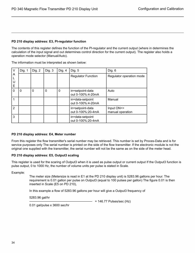
PD 210 display address: E3, Pl-regulator function
The contents of this register defines the function of the Pl-regulator and the current output (where in determines the calculation of the input signal and out determines control direction for the current output). The register also holds a operation mode selector (Manual/Auto).
The information must be interpreted as shown below:
VALUE
Dig. 1 Dig. 2 Dig. 3 Dig. 4 Dig. 5 Dig. 6
Regulator Function Regulator operation mode
0 0 0 0 0 in=setpoint-dataout 0-100%:4-20mA
Auto
1 in=data-setpointout 0-100%:4-20mA
Manual
2 in=setpoint-dataout 0-100%:20-4mA
Input ON=>manual operation
3 in=data-setpointout 0-100%:20-4mA
PD 210 display address: E4, Meter number
From this register the flow transmitter's serial number may be retrieved. This number is set by Proces-Data and is for service purposes only The serial number is printed on the side of the flow transmitter. lf the electronic module is not the original one supplied with the transmitter, the serial number will not be the same as on the side of the meter head.
PD 210 display address: E5, Output3 scaling
This register is used for the scaring of Output3 when it is used as pulse output or current output If the Output3 function is pulse output, 0 to 1000 Hz, the number of volume units per pulse is stated in Scale.
Example:The meter size (Metersize is read in E1 at the PD 210 display unit) is 5283.96 gallons per hour. The requirement is 0.01 gallon per pulse on Output3 (equal to 100 pulses per gallon) The figure 0.01 is then inserted in Scale (E5 on PD 210),
In this example a flow of 5283.96 gallons per hour will give a Output3 frequency of
5283.96 gal/hr = 146.77 Pulses/sec (Hz)0.01 gal/pulse x 3600 sec/hr

PD 340 Magnetic Flow Transmitter PD 210 Display Unit
35
Configuration and Calibration
NOTE: Be sure that the frequency on the output does not exceed 1000) Hz.
lf the Output3 function is current output, 4 - 20 mA, Scale will indicate the full scale value of the data for the current output
Example:
Full scale (20 mA) is desired on the current output at 5000 gallons per hour. The number 5000 is inserted in Scale. 4 mA always equals a measuring result of 0.
lf the function of Output3 is Pl-regulator, Scale will indicate the proportional band of the regulator, The proportional band for a regulator is the change required in the input signal to give a change from O to 100% in the output signal (without I). The proportional band is defined in the same unit, as the input signal to the regulator - e.g. gal/hr, See also the application example on page 23.
PD 210 display address: E6, Display resolution
Using the display unit, various parameters may be read out from the flow transmitter. For these values, E6 determines how many digits to appear after the decimal point. The resolution may be in the range from 0 to 6.
The information must be interpreted as shown below: Digit 1 Digit 2 Digit 3 Digit 4 Digit 5 Digit 6Flow TCFlow Volume1 Volume2 Setpoint Instantflow
For digit 3, Volume 1 , and digit 4, Volume2, the resolution determines also the maximum value for the counters, ie. the overflow value. See also the description for Volume1 on page 32.
Example:
The size of the transmitter is 21 1 3.58 gal/hr. Flow is requested on the display with a resolution of 0. 1 gal/hr. Set digit 1 in E6 equal to 2 (2 digits after the decimal point).
When the Outputs function is pulse output, 0 - 10 Hz, the resolution on Volume1 (Digit 3) indicates the resolution on the display read out as well as the pulse output, Outputs will give a pulse each time the least significant digit changes on the display.

PD 340 Magnetic Flow Transmitter PD 210 Display Unit
36
Configuration and Calibration
E6, Digit 3 Gal/Pulse Pulse/Gal0 1 11 0.1 102 0.01 1003 0.001 1000
Example:
In MeterSize the size of the transmitter is specified to be 2113.58 gal/hr. On Output2, 1 pulse is required for each 0.1 gal. Digit 3 in E6 is set to 1 (1 digit after the decimal point). At a flow of 2113.58 gal/hr the frequency on Output2 is
2113.58 gal/hr = 5.87 Hz0.01 gal/pulse x 3600 sec/hr
Note: Resolution must be chosen so the frequency on Output2 does not exceed 10 Hz.
jPD 210 display address: E7
The contents of E7 defines the functions of Output2, the functions and control data for Output3, data for volume counters, data for the batch control/limit switch and the operation mode for the flow transmitter.
The information must be interpreted as shown below.
Value
Dig. 1 Dig. 2 Dig. 3 Dig. 4 Dig. 5 Dig. 6
Function Output3
Data for Output3
Function Output2
Data for vol counter Mode
Data for batch control/limit switch
0 No function No function No function No counting Normal No batch/limit1 PI-regulator Flow Pulse output
1-10HzFlow Flow
2 Current output, 4-20mA
TCFlow Batch control TCFlow TCFlow
3 Temp Temp4 Pulse output,
0 - 100 HzAvailable Limit switch Available
5 Volume16 Error code=0 Volume278 Instantflow Sign for
Output3Instantflow TEST Instantflow
PD 340 Magnetic Flow Transmitter PD 210 Display Unit
37
Configuration and Calibration
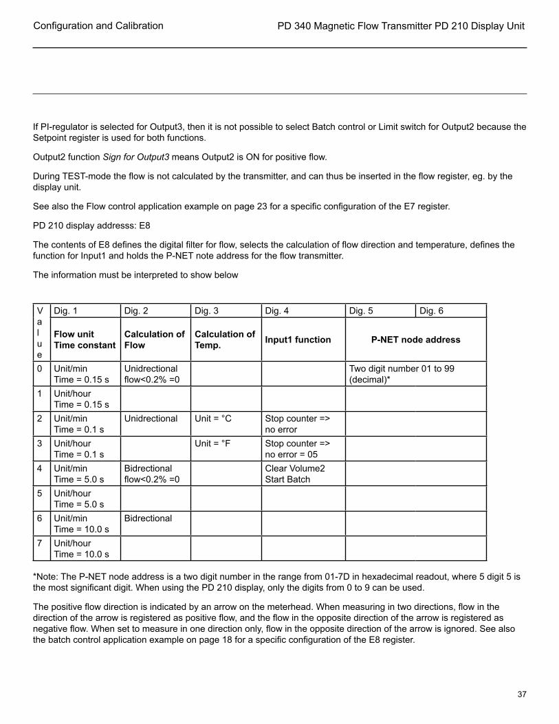
If PI-regulator is selected for Output3, then it is not possible to select Batch control or Limit switch for Output2 because the Setpoint register is used for both functions.
Output2 function Sign for Output3 means Output2 is ON for positive flow.
During TEST-mode the flow is not calculated by the transmitter, and can thus be inserted in the flow register, eg. by the display unit.
See also the Flow control application example on page 23 for a specific configuration of the E7 register.
PD 210 display addresss: E8
The contents of E8 defines the digital filter for flow, selects the calculation of flow direction and temperature, defines the function for Input1 and holds the P-NET note address for the flow transmitter.
The information must be interpreted to show below
Value
Dig. 1 Dig. 2 Dig. 3 Dig. 4 Dig. 5 Dig. 6
Flow unit Time constant
Calculation of Flow
Calculation of Temp. Input1 function P-NET node address
0 Unit/minTime = 0.15 s
Unidrectional flow<0.2% =0
Two digit number 01 to 99 (decimal)*
1 Unit/hourTime = 0.15 s
2 Unit/minTime = 0.1 s
Unidrectional Unit = °C Stop counter => no error
3 Unit/hourTime = 0.1 s
Unit = °F Stop counter => no error = 05
4 Unit/minTime = 5.0 s
Bidrectional flow<0.2% =0
Clear Volume2 Start Batch
5 Unit/hourTime = 5.0 s
6 Unit/minTime = 10.0 s
Bidrectional
7 Unit/hourTime = 10.0 s
*Note: The P-NET node address is a two digit number in the range from 01-7D in hexadecimal readout, where 5 digit 5 is the most significant digit. When using the PD 210 display, only the digits from 0 to 9 can be used.
The positive flow direction is indicated by an arrow on the meterhead. When measuring in two directions, flow in the direction of the arrow is registered as positive flow, and the flow in the opposite direction of the arrow is registered as negative flow. When set to measure in one direction only, flow in the opposite direction of the arrow is ignored. See also the batch control application example on page 18 for a specific configuration of the E8 register.

PD 340 Magnetic Flow Transmitter PD 210 Display Unit
38
Configuration and Calibration
Standard Settings.
If specific configuration is not requested at the time of order, the flow meter will be shipped with the following configurations.
PD 210 Reg. 1" C25 1½" (C38) 2" (C51) 2½" (C63) 3" (C76)
E1 Meter size 2113.58 5283.96 10567.9 21135.8 31703.8
E2 Integration Time TI 000000 000000 000000 000000 000000
E3 PI Code 000000 000000 000000 000000 000000
E4 Serial No. -- -- -- -- --
E5 Scale Standard Extended.01000035.2263
.01000088.0660
.010000176.132
.010000352.263
.010000528.395
E6 Resolution 222222 222222 222222 222222 222222
E7 Outputs 2 & 3 Standard Extended410100210100
410100210100
410100210100
410100210100
410100210100
E8 Flow function 203400 203400 203400 203400 203400
PD 340 Magnetic Flow Transmitter PD 210 Display Unit
39
Error Detection
Error detection.
The PD 340 flow transmitter is equipped with a comprehensive self testing system which is able to indicate faults arising from improper use of the transmitter, or faults arising while the transmitter is in use
When the internal test system registers a fault, an error code, in the form of a number, is generated within the flow transmitter. lf several errors in the error checking system should develop at the same time, only the highest numbered error is saved.
PD 210 display unit:
The user is informed by an ''A'' for ALARM appearing in the first digit of the display. By pressing the ''TEST'' button the display will show an error code of two digits, indicating the type of error. The test system ensures that the alarm will not be cancelled before the error code has been displayed by pressing the ''TEST'' button, even though the error may have disappeared By pressing the ''TEST'' button once again, the display will show "0" if the flow transmitter is error free now. The error code on the display is only updated by re-pressing the ''TEST'' button.

PD 340 Magnetic Flow Transmitter PD 210 Display Unit
40
Error Detection
Typical errors.
Flow transmitter with PD 210 display unit.
lf neither the transmitter nor the display unit functions:
Check:
that the light-emitting diode in the terminal box is on.•
that the transmitter is correctly connected.•
that the supply voltage at the flow transmitter is at least 20 VAC or DC, when the transmitter is • powered up (with the terminal box mounted on the transmitter).
If the display unit does not function:
Check:
that the cable between the transmitter and the display unit is correctly connected at both ends.•
that the cable is not defective.•
that the cable is not too long or too thin (max. 325ft, min. 24 ga).•
If external equipment, e.g. an electronic counter, does not function, or does not function properly:
Check:
that the equipment is correctly connected.•
that the transmitter data is being displayed correctly (using PD 210) •
that the required functions for the output signals have been correctly set •
that the meter size is correct (using PD 210) •
If the transmitter does not indicate flow:
Check:
that there really is flow through the metering pipe.•
that the flow direction is correct.•
If the transmitter gives a false read-out:
Check:
if there is any air in the liquid •
that the conductivity of the liquid lies within the specified range.•

PD 340 Magnetic Flow Transmitter PD 210 Display Unit
41
Error Detection
Flow transmitter without display unit.
If the transmitter does not function:
Check:
that the light-emitting diode in the terminal box is on.•
that the transmitter is correctly connected.•
that the supply voltage • at the transmitter is at least 20 V AC or DC, when the transmitter is powered up (with the terminal box mounted on the transmitter).
that there really is flow through the metering pipe.•
that the flow direction is correct.•
If the transmitter gives a false read-out:
Check:
if there is any air in the liquid.•
that the conductivity of the liquid lies within the specified range.•

PD 340 Magnetic Flow Transmitter PD 210 Display Unit
42
Specifications
Material.
Electrodes: Stainless steel AISI 316.
Metering pipe: Stainless steel AISI 316.
Coating inside metering pipe: FEP Teflon
Housing: PPO Noryl.
Connections.
GC Clamp Sanitary.
Flow measurement accuracy
Accuracy.
All electrical characteristics are valid at an ambient temperature +14ºF to +122ºF, unless otherwise stated.
All specifications are in compliance with in the approved EMI conditions. EMC test specifications for PD 340 are available in a separate document, PD no. 506 023.
Max. Error Against Actual Flow Rate
Flow measurement error: typ. less than half the value as shown on figure
Current output error: As in figure, plus +/-0.3% of current output range
Linearity: See figure
Repeatability: max (0.5 · error), see figure
Ambient temperature effect: max 0.4%/50ºF
Voltage supply effect: max 0.01%/10%
Response time pulse output: 0.2 sec.Response time current output: 1.0 sec.

PD 340 Magnetic Flow Transmitter PD 210 Display Unit
43
Specifications
Power supply.
The transmitter should always have the supply connected to prevent condensation in the electronics.
Power supply AC (50.60 Hz) or DC: nom. 24.0 V Min. 20.0 V Max. 28.0 V
Current at powerup: max. 350 mA
Fuse (time lag) 0.8 A
Power consumption: max. 6W
Digital Outputs: Two independent, scalable non-voltage Open collector OPTO-isolated pulse outputs.
Pulse Width: 40 msec Output 2 -- 10Hz maximum Output 3 -- 1000 Hz maximum
Analog Option: Output 3 -- 4-20mA Adjustable time constant
Discrete Input: One discrete input: Remotely reset PD210 totalizer Or disable meter outputEntry Wiring: Water tight cord grip -- three unit supplied (pg 11 thread)
Liquid.
Conductivity: min 5 µs/cm.
Temperature range: -22°F to +212°F
Pressure: max. 145 PSI
Pressure test: max. 360 PSI
Measurement of temperature.
Temperature input with 100 ohm 4 wire RTD sensor (IEC 751, DIN 43760)
Error: max =/-1.6°F
PD 340 Magnetic Flow Transmitter PD 210 Display Unit
44
Specifications
Environment.
Ambient temperature: +14°F to +122°F
Protection: IP 67/NEMA 4
Approvals.
Compliance with EMC-directive no.: 89/336/ECCGeneric standards for emission: Residential, commercial and light industry EN 50081-1 Industry EN 50081-2
Generic standards for immunity: Residential, commercial and light industry EN 50082-1 Industry EN 50082-2
Vibration (sinusoidal): IEC 68-2-6 Test Fc
PD 340 Magnetic Flow Transmitter PD 210 Display Unit
45
Memory Types
Memory types.
The PD 340 stores data in different types of memory depending on the value of a control variable following a reset or a power failure, and the state of write protection.
Some variables are stored in both non volatile memory and in volatile memory. The state of the module's Program enable switch determines whether the contents are changed in both types of memory or only in the volatile type.
The following memory types are listed on page 27.
Read Only
PROM ReadOnly
The PROM is always write protected and can never be changed.
RAM Readably
The variable is stored in RAM and is only accessible for Reading,
Read Protected Write
EEPROM RPW (Read, Protected Write)
By setting the Program Enable switch to ON, the contents of the EEPROM can be changed. The contents of the EEPROM will remain unchanged during and after a power failure.
Read Write
RAM ReadWrite
The variable can be changed instantly. After reset or a power failure, it's value is set to zero,
Read Write, Protected Backup Write
RAM InitEEPROM The variable is stored in both RAM and EEPROM. After a reset, the variable is copied from EEPROM into RAM.
When the variable is changed, the value is changed in RAM. If the ProgramEnable switch is ON, the value is changed in both RAM and EEPROM when the variable is changed

PD 340 Magnetic Flow Transmitter PD 210 Display Unit
46
PD 340 Configuration Notes
PD340 Configuration
Inputs
24 VAC/DC PowerPD210DisplayInput-1 24 VDC100 OHM PT. Bulb
Terminal Block5, 63, 416, 1717, 1813, 14, 151, 27, 819, 209, 10, 11, 12
OutputsOutput1Output2Output3Output3P_NET
State24 V PowerPulses (0-10 Hz)Pulses (0-1000Hz)4-20 mAFieldbus Interface
Flow Rate (Units/HR) = HzResolution/Pulse X 3600 Sec/HR
Sizing Information
Size1" 25mm 8 m3/h= 2113.58 Gals/Hr. = 35GPM1½" 38mm 20 m3/h= 5283.96 Gals/Hr. = 88GPM2" 51mm 40 m3/h= 10567.92 Gals/Hr. = 176GPM2½” 63mm 80 m3/h= 21135.84 Gals/Hr. = 352GPM3" 76mm 120 m3/h= 31703.76 Gals/Hr. = 528GPM

PD 340 Magnetic Flow Transmitter PD 210 Display Unit
47
PD 340 Configuration Notes
Dig. 1 Dig. 2 Dig. 3 Dig. 4 Dig. 5 Dig. 6
E1: Meter Size
E2: Ti (Integration Time)
E3: PI-Code (Function)
E4: Serial Number
E5: Scale/Proportional Band
E6: Resolution
E7: Output Specifications
E*: Calculation; Temp or Flow
(Record your input information here.)

PD 340 Magnetic Flow Transmitter PD 210 Display Unit
48
Drawing/Parts List

PD 340 Magnetic Flow Transmitter PD 210 Display Unit
49
Drawing/Parts List
The items are identical with the item in the Spare Parts List. When ordering spare parts, please use the Spare Parts List.
Parts List
Pos. Qty. Description1 1 Electronic Module-Extended version/Standard version2 1 Meterhead3 1 Terminal Box4 1 PD 210 Meter Display/Programming Unit5 1 Electronic Module/Terminal Box6 1 Meter head gasket7 1 Terminal Box Binding Plug8 1 Plastic Cord Grip Pg-11

PD 340 Magnetic Flow Transmitter PD 210 Display Unit
50
Information
This page may be used for notes concerning the flow meter.
The best way to produce user-friendly manuals is through feedback from the user. - Please see below
1. Notes
_________________________________________________________________________________________________
_________________________________________________________________________________________________
_________________________________________________________________________________________________
_________________________________________________________________________________________________
_________________________________________________________________________________________________
_________________________________________________________________________________________________
_________________________________________________________________________________________________
_________________________________________________________________________________________________
_________________________________________________________________________________________________
_________________________________________________________________________________________________
_________________________________________________________________________________________________
_________________________________________________________________________________________________
_________________________________________________________________________________________________
_________________________________________________________________________________________________
_________________________________________________________________________________________________
_________________________________________________________________________________________________
2. User Feedback
Our goal is to produce instruction manuals that meet your needs. If you have any comments which may help us in our efforts to improve this manual, please do not hesitate to send them to us.
Alfa Laval Inc.9560 58th Place, Suite 300Kenosha, WI 53144Phone: +1 800 558 4060Fax: +1 800 781 2777E-mail: [email protected] our web site at www.alfalaval.us