Embed Size (px)
Citation preview
3200NXTService Manual
IMPORTANT: Fill in Pertinent Information on Page 3 for Future Reference
Job Specification Sheet.......................................................................................................................................... 3Timer Operation...................................................................................................................................................... 4Timer Display Features.......................................................................................................................................... 6Timer Display - Screen Examples.......................................................................................................................... 7Network/Communication Cables & Connections.................................................................................................... 8Master Programming Mode Flow Chart................................................................................................................. 9Master Programming Guide................................................................................................................................. 13User Mode Programming Flow Chart................................................................................................................... 20Diagnostic Mode Flow Chart................................................................................................................................ 21Diagnostic Programming Guide........................................................................................................................... 222750/2850/2900 Upper & 2900 Lower Powerhead Assy...................................................................................... 263150/3900 Upper & 3900 Lower Drive Powerhead Assy..................................................................................... 282750/2850/3150 Input & Output Wiring................................................................................................................ 302900/3900 Input & Output Wiring......................................................................................................................... 31Troubleshooting.................................................................................................................................................... 32
Table of Contents
IMPORTANT PLEASE READ: The information, specifications and illustrations in this manual are based on the latest information available at the time of printing. The manufacturer reserves the right to make changes at any time without notice.This manual is intended as a guide for service of the valve only. System installation requires information from a number of suppliers not known at the time of manufacture. This product should be installed by a plumbing professional.This unit is designed to be installed on potable water systems only.This product must be installed in compliance with all state and municipal plumbing and electrical codes. Permits may be required at the time of installation.If daytime operating pressure exceeds 80 psi, nighttime pressures may exceed pressure limits. A pressure reducing valve must be installed. Do not install the unit where temperatures may drop below 32°F (0°C) or above 125°F (52°C). Do not place the unit in direct sunlight. Black units will absorb radiant heat increasing internal temperatures. Do not strike the valve or any of the components.Warranty of this product extends to manufacturing defects. Misapplication of this product may result in failure to properly condition water, or damage to product.A prefilter should be used on installations in which free solids are present. In some applications local municipalities treat water with Chloramines. High Chloramine levels may damage valve components.Correct and constant voltage must be supplied to the control valve to maintain proper function.
•
•
••
•
••••
•••
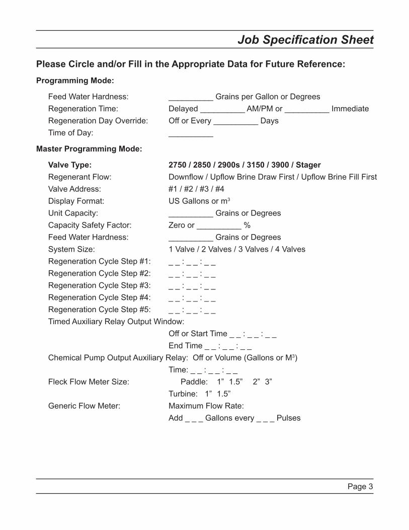
Please Circle and/or Fill in the Appropriate Data for Future Reference:Programming Mode:
Feed Water Hardness: __________ Grains per Gallon or Degrees Regeneration Time: Delayed __________ AM/PM or __________ Immediate Regeneration Day Override: Off or Every __________ Days Time of Day: __________
Master Programming Mode:
Valve Type: 2750 / 2850 / 2900s / 3150 / 3900 / Stager Regenerant Flow: Downflow / Upflow Brine Draw First / Upflow Brine Fill First Valve Address: #1 / #2 / #3 / #4 Display Format: US Gallons or m3. . .
Unit Capacity: __________ Grains or Degrees Capacity Safety Factor: Zero or __________ % Feed Water Hardness: __________ Grains or Degrees System Size: 1 Valve / 2 Valves / 3 Valves / 4 Valves Regeneration Cycle Step #1: _ _ : _ _ : _ _ Regeneration Cycle Step #2: _ _ : _ _ : _ _ Regeneration Cycle Step #3: _ _ : _ _ : _ _ Regeneration Cycle Step #4: _ _ : _ _ : _ _ Regeneration Cycle Step #5: _ _ : _ _ : _ _ Timed Auxiliary Relay Output Window: Off or Start Time _ _ : _ _ : _ _ End Time _ _ : _ _ : _ _ Chemical Pump Output Auxiliary Relay: Off or Volume (Gallons or M3) Time: _ _ : _ _ : _ _ Fleck Flow Meter Size: Paddle: 1” 1.5” 2” 3” Turbine: 1” 1.5” Generic Flow Meter: Maximum Flow Rate: Add _ _ _ Gallons every _ _ _ Pulses
Page 3
Job Specification Sheet
Page 4
Timer Operation
Setting the Time of DayNOTE: Set Time of Day on the Lead Unit (#1) and the rest of the units in the system will populare with the Time of Day within 10 seconds.
Press and hold the Up or Down button for 2 seconds. Press the Shift button to select the digit you want to modify.Press the Up or Down buttons to adjust the value.Press the Extra Cycle button to return to the normal display screen, or after a 5 second timeout.
NOTE: The “D” button (Diagnostic) can be pressed to exit without saving.
Manually Initiating a RegenerationWhen timer is in service, press the Extra Cycle button for 5 seconds on the main screen.The timer advances to Regeneration Cycle Step #1, and begins programmed time count down.Press the Extra Cycle button once to advance valve to Regeneration Cycle Step #2 (if active).Press the Extra Cycle button once to advance valve to Regeneration Cycle Step #3 (if active).Press the Extra Cycle button once to advance valve to Regeneration Cycle Step #4 (if active).Press the Extra Cycle button once to advance valve to Regeneration Cycle Step #5 (if active).Press the Extra Cycle button once more to advance the valve back to in service.
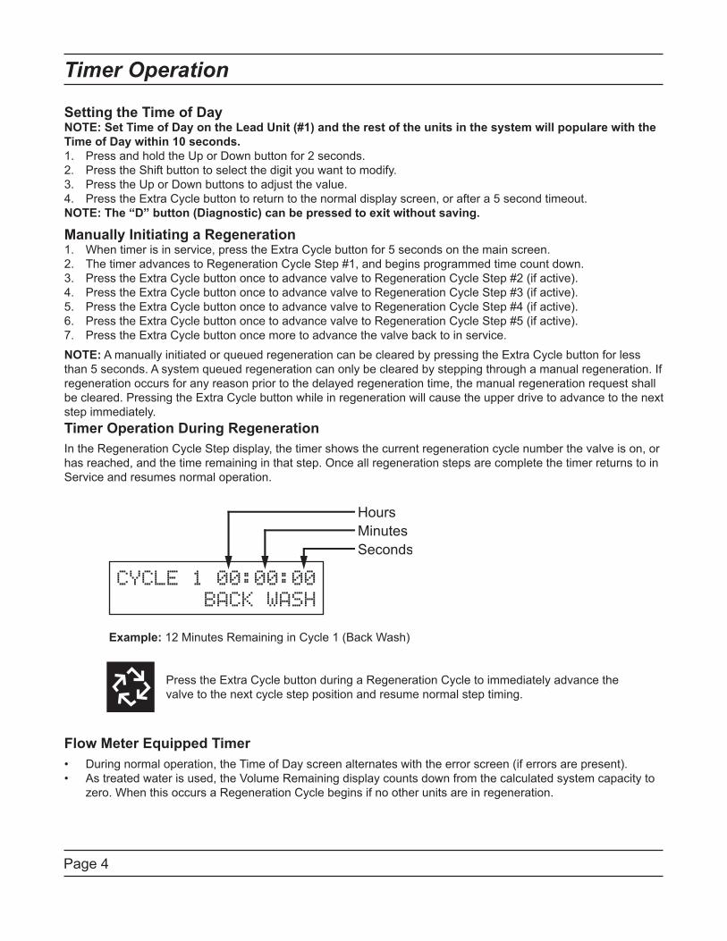
NOTE: A manually initiated or queued regeneration can be cleared by pressing the Extra Cycle button for less than 5 seconds. A system queued regeneration can only be cleared by stepping through a manual regeneration. If regeneration occurs for any reason prior to the delayed regeneration time, the manual regeneration request shall be cleared. Pressing the Extra Cycle button while in regeneration will cause the upper drive to advance to the next step immediately.Timer Operation During RegenerationIn the Regeneration Cycle Step display, the timer shows the current regeneration cycle number the valve is on, or has reached, and the time remaining in that step. Once all regeneration steps are complete the timer returns to in Service and resumes normal operation.
1.2.3.4.
1.2.3.4.5.6.7.
Example: 12 Minutes Remaining in Cycle 1 (Back Wash)
Press the Extra Cycle button during a Regeneration Cycle to immediately advance the valve to the next cycle step position and resume normal step timing.
Flow Meter Equipped TimerDuring normal operation, the Time of Day screen alternates with the error screen (if errors are present).As treated water is used, the Volume Remaining display counts down from the calculated system capacity to zero. When this occurs a Regeneration Cycle begins if no other units are in regeneration.
••
CYCLE 1 00:00:00
BACK WASH
Page 5
Timer Operation
Timer Operation During ProgrammingThe timer enters the Program Mode in standby or service mode as long as it is not in regeneration. While in the Program Mode the timer continues to operate normally monitoring water usage. Timer programming is stored in memory permanently.
Timer Operation During A Power FailureAll program settings are stored in permanent memory. Current valve position, cycle step time elapsed, and time of day are stored during a power failure, and will be restored upon power re-application. Time is kept during a power failure, and time of day is adjusted upon power up (as long as power is restored within 12 hours).NOTE: The time of day on the main display screen will flash for 5 minutes when there has been a power outage. The flashing of the time of day can be stopped by pressing any button on the display.Remote LockoutThe timer does not allow the unit/system to go into Regeneration until the Regeneration Lockout Input signal to the unit is cleared. This requires a contact closure to activate the unit. The recommended gauge wire is 20 with a maximum length of 500 feet. See P4 remote inputs in the wiring diagrams in the service manual.
Regeneration Day Override FeatureIf the Day Override option is turned on and the valve reaches the set Regeneration Day Override value, the Regeneration Cycle starts if no other unit is in Regeneration. If other units are in regeneration, it is added to a regeneration queue. This occurs regardless of the remaining volume available.
Page �
Timer Display Features
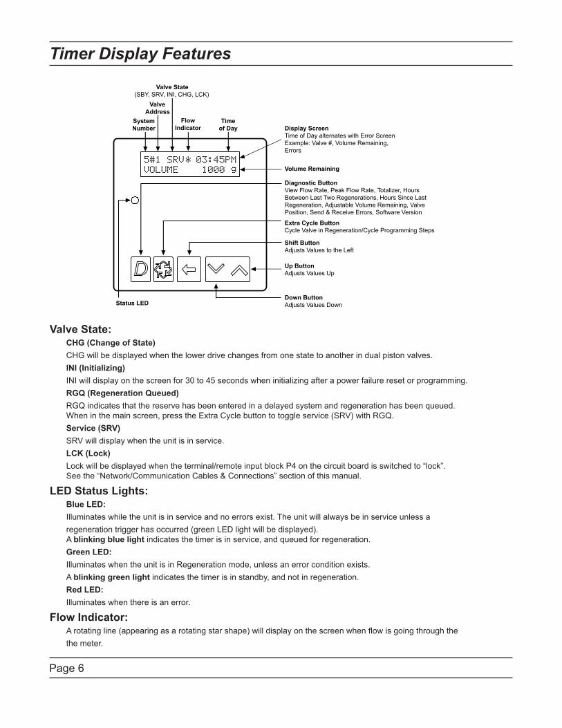
SystemNumber
ValveAddress
Valve State(SBY, SRV, INI, CHG, LCK)
FlowIndicator
Timeof Day Display Screen
Time of Day alternates with Error ScreenExample: Valve #, Volume Remaining,Errors
Diagnostic ButtonView Flow Rate, Peak Flow Rate, Totalizer, HoursBetween Last Two Regenerations, Hours Since LastRegeneration, Adjustable Volume Remaining, ValvePosition, Send & Receive Errors, Software Version
Extra Cycle ButtonCycle Valve in Regeneration/Cycle Programming Steps
Shift ButtonAdjusts Values to the Left
Up ButtonAdjusts Values Up
Down ButtonAdjusts Values Down
Volume Remaining
Status LED
Valve State: CHG (Change of State) CHG will be displayed when the lower drive changes from one state to another in dual piston valves. INI (Initializing) INI will display on the screen for 30 to 45 seconds when initializing after a power failure reset or programming. RGQ (Regeneration Queued) RGQ indicates that the reserve has been entered in a delayed system and regeneration has been queued. . When in the main screen, press the Extra Cycle button to toggle service (SRV) with RGQ. Service (SRV) SRV will display when the unit is in service. LCK (Lock) Lock will be displayed when the terminal/remote input block P4 on the circuit board is switched to “lock”.. See the “Network/Communication Cables & Connections” section of this manual.
LED Status Lights: Blue LED: Illuminates while the unit is in service and no errors exist. The unit will always be in service unless a regeneration trigger has occurred (green LED light will be displayed). . A blinking blue light indicates the timer is in service, and queued for regeneration. Green LED: Illuminates when the unit is in Regeneration mode, unless an error condition exists. A blinking green light indicates the timer is in standby, and not in regeneration. Red LED: Illuminates when there is an error.
Flow Indicator: A rotating line (appearing as a rotating star shape) will display on the screen when flow is going through the the meter.
Page 7
Timer Display - Screen Examples
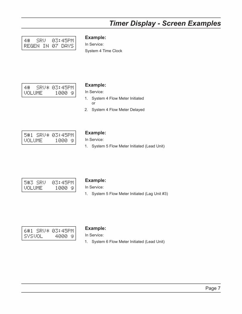
Example:In Service:System 4 Time Clock
Example:In Service:
System 4 Flow Meter Initiated.orSystem 4 Flow Meter Delayed
1.
2.
Example:In Service:
System 5 Flow Meter Initiated (Lead Unit)1.
Example:In Service:
System 5 Flow Meter Initiated (Lag Unit #3)1.
Example:In Service:
System � Flow Meter Initiated (Lead Unit)1.
Page 8
Network/Communication Cables & Connections
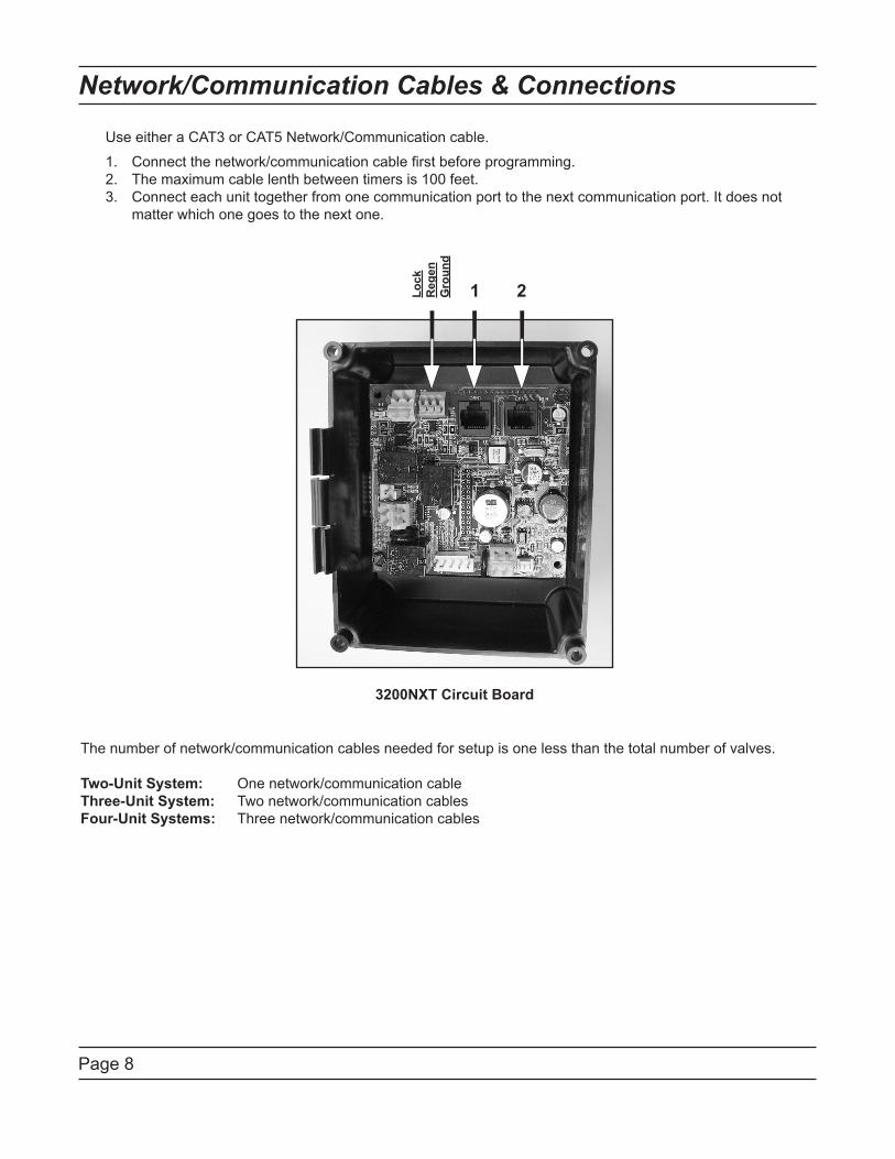
The number of network/communication cables needed for setup is one less than the total number of valves.
Two-Unit System: One network/communication cableThree-Unit System: Two network/communication cablesFour-Unit Systems: Three network/communication cables
3200NXT Circuit Board
1 2Lock
Reg
enG
roun
d
Use either a CAT3 or CAT5 Network/Communication cable.
1. Connect the network/communication cable first before programming. 2. The maximum cable lenth between timers is 100 feet. 3. Connect each unit together from one communication port to the next communication port. It does not . matter which one goes to the next one.
Page 9
Master Programming Mode Flow Chart
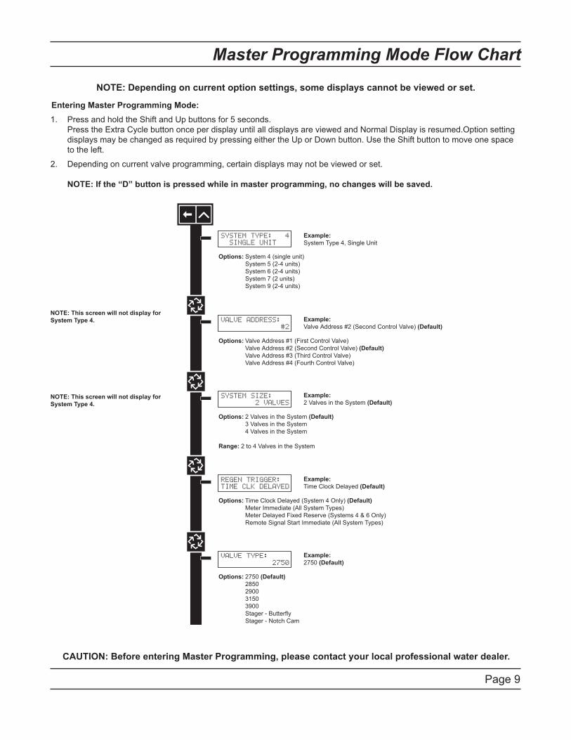
Entering Master Programming Mode:Press and hold the Shift and Up buttons for 5 seconds..Press the Extra Cycle button once per display until all displays are viewed and Normal Display is resumed.Option setting displays may be changed as required by pressing either the Up or Down button. Use the Shift button to move one space to the left.
Depending on current valve programming, certain displays may not be viewed or set...NOTE: If the “D” button is pressed while in master programming, no changes will be saved.
1.
2.
CAUTION: Before entering Master Programming, please contact your local professional water dealer.
SYSTEM TYPE: 4 SINGLE UNIT
Options: System 4 (single unit) System 5 (2-4 units) System 6 (2-4 units) System 7 (2 units) System 9 (2-4 units)
VALVE ADDRESS: #2
Options: Valve Address #1 (First Control Valve) Valve Address #2 (Second Control Valve) (Default) Valve Address #3 (Third Control Valve) Valve Address #4 (Fourth Control Valve)
Example:System Type 4, Single Unit
Example:Valve Address #2 (Second Control Valve) (Default)
SYSTEM SIZE: 2 VALVES
Options: 2 Valves in the System (Default) 3 Valves in the System 4 Valves in the System
Range: 2 to 4 Valves in the System
Example:2 Valves in the System (Default)
REGEN TRIGGER:TIME CLK DELAYED
Options: Time Clock Delayed (System 4 Only) (Default) Meter Immediate (All System Types) Meter Delayed Fixed Reserve (Systems 4 & 6 Only) Remote Signal Start Immediate (All System Types)
Example:Time Clock Delayed (Default)
VALVE TYPE: 2750
Options: 2750 (Default) 2850 2900 3150 3900 Stager - Butterfly Stager - Notch Cam
Example:2750 (Default)
NOTE: This screen will not display forSystem Type 4.
NOTE: This screen will not display forSystem Type 4.
NOTE: This screen will only display on the lead unit for System Types 6 & 7.For all other System Types, it will display for all units.
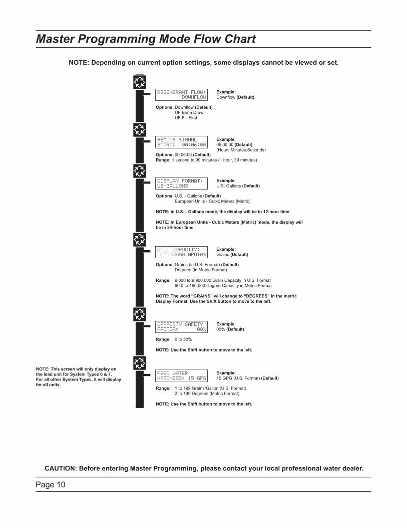
REGENERANT FLOW: DOWNFLOW
Options: Downflow (Default) UF Brine Draw UF Fill First
Example:Downflow (Default)
REMOTE SIGNALSTART: 00:06:00
Options: 00:06:00 (Default)Range: 1 second to 99 minutes (1 hour, 39 minutes)
Example:06:00:00 (Default)(Hours:Minutes:Seconds)
DISPLAY FORMAT:US-GALLONS
Options: U.S. - Gallons (Default) European Units - Cubic Meters (Metric)
NOTE: In U.S. - Gallons mode, the display will be in 12-hour time.
NOTE: In European Units - Cubic Meters (Metric) mode, the display willbe in 24-hour time.
Example:U.S. Gallons (Default)
UNIT CAPACITY: 00000000 GRAINS
Options: Grains (in U.S. Format) (Default) Degrees (in Metric Format)
Range: 9,000 to 9,900,000 Grain Capacity in U.S. Format 90.0 to 190,000 Degree Capacity in Metric Format
NOTE: The word “GRAINS” will change to “DEGREES” in the metricDisplay Format. Use the Shift button to move to the left.
Example:Grains (Default)
CAPACITY SAFETYFACTOR: 00%
Range: 0 to 50%
NOTE: Use the Shift button to move to the left.
Example:00% (Default)
FEED WATERHARDNESS: 15 GPG
Range: 1 to 199 Grains/Gallon (U.S. Format) 2 to 199 Degrees (Metric Format)
NOTE: Use the Shift button to move to the left.
Example:15 GPG (U.S. Format) (Default)
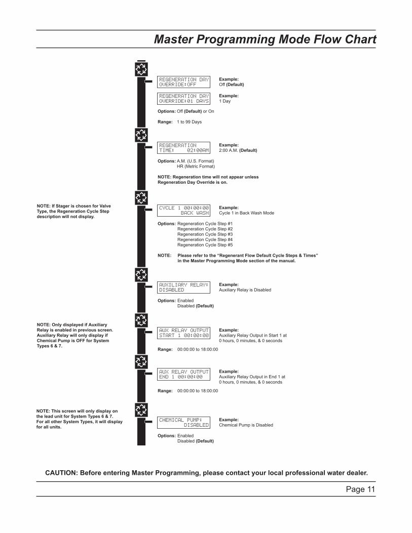
REGENERATION DAYOVERRIDE:OFF
Example:Off (Default)
REGENERATION DAYOVERRIDE:01 DAYS
Options: Off (Default) or On
Range: 1 to 99 Days
Example:1 Day
CYCLE 1 00:00:00 BACK WASH
Example:Cycle 1 in Back Wash Mode
Options: Regeneration Cycle Step #1 Regeneration Cycle Step #2 Regeneration Cycle Step #3 Regeneration Cycle Step #4 Regeneration Cycle Step #5
NOTE: Please refer to the “Regenerant Flow Default Cycle Steps & Times” in the Master Programming Mode section of the manual.
AUXILIARY RELAY:DISABLED
Example:Auxiliary Relay is Disabled
Options: Enabled Disabled (Default)
CHEMICAL PUMP: DISABLED
Example:Chemical Pump is Disabled
Options: Enabled Disabled (Default)
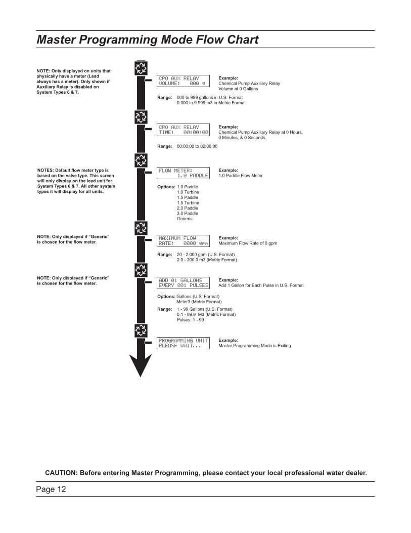
CPO AUX RELAYVOLUME: 000 g
Example:Chemical Pump Auxiliary RelayVolume at 0 Gallons
Range: 000 to 999 gallons in U.S. Format 0.000 to 9.999 m3 in Metric Format
CPO AUX RELAYTIME: 00:00:00
Example:Chemical Pump Auxiliary Relay at 0 Hours,0 Minutes, & 0 Seconds
Range: 00:00:00 to 02:00:00
FLOW METER: 1.0 PADDLE
Example:1.0 Paddle Flow Meter
Options: 1.0 Paddle 1.0 Turbine 1.5 Paddle 1.5 Turbine 2.0 Paddle 3.0 Paddle Generic
MAXIMUM FLOWRATE: 0000 gpm
Example:Maximum Flow Rate of 0 gpm
Range: 20 - 2,000 gpm (U.S. Format) 2.0 - 200.0 m3 (Metric Format)
Range: 1 - 99 Gallons (U.S. Format) 0.1 - 09.9 M3 (Metric Format) Pulses: 1 - 99
PROGRAMMING UNITPLEASE WAIT...
Example:Master Programming Mode is Exiting
REGENERATIONTIME: 02:00AM
Example:2:00 A.M. (Default)
Options: A.M. (U.S. Format) HR (Metric Format)
NOTE: Regeneration time will not appear unlessRegeneration Day Override is on.
Options: Gallons (U.S. Format) Meter3 (Metric Format)
ADD 01 GALLONSEVERY 001 PULSES
Example:Add 1 Gallon for Each Pulse in U.S. Format
AUX RELAY OUTPUTSTART 1 00:00:00
Example:Auxiliary Relay Output in Start 1 at 0 hours, 0 minutes, & 0 seconds
Range: 00:00:00 to 18:00:00
AUX RELAY OUTPUTEND 1 00:00:00
Example:Auxiliary Relay Output in End 1 at 0 hours, 0 minutes, & 0 seconds
Range: 00:00:00 to 18:00:00
NOTE: Only displayed if Auxiliary Relay is enabled in previous screen. Auxiliary Relay will only display if Chemical Pump is OFF for SystemTypes 6 & 7.
NOTE: If Stager is chosen for Valve Type, the Regeneration Cycle Stepdescription will not display.
NOTE: Only displayed on units thatphysically have a meter (Leadalways has a meter). Only shown if Auxiliary Relay is disabled on System Types 6 & 7.
NOTES: Default flow meter type isbased on the valve type. This screenwill only display on the lead unit for System Types 6 & 7. All other systemtypes it will display for all units.
NOTE: Only displayed if “Generic”is chosen for the flow meter.
NOTE: Only displayed if “Generic”is chosen for the flow meter.
NOTE: This screen will only display on the lead unit for System Types 6 & 7.For all other System Types, it will display for all units.
NOTE: Depending on current option settings, some displays cannot be viewed or set.
Page 10
Master Programming Mode Flow Chart
CAUTION: Before entering Master Programming, please contact your local professional water dealer.
NOTE: Depending on current option settings, some displays cannot be viewed or set.
SYSTEM TYPE: 4 SINGLE UNIT
Options: System 4 (single unit) System 5 (2-4 units) System 6 (2-4 units) System 7 (2 units) System 9 (2-4 units)
VALVE ADDRESS: #2
Options: Valve Address #1 (First Control Valve) Valve Address #2 (Second Control Valve) (Default) Valve Address #3 (Third Control Valve) Valve Address #4 (Fourth Control Valve)
Example:System Type 4, Single Unit
Example:Valve Address #2 (Second Control Valve) (Default)
SYSTEM SIZE: 2 VALVES
Options: 2 Valves in the System (Default) 3 Valves in the System 4 Valves in the System
Range: 2 to 4 Valves in the System
Example:2 Valves in the System (Default)
REGEN TRIGGER:TIME CLK DELAYED
Options: Time Clock Delayed (System 4 Only) (Default) Meter Immediate (All System Types) Meter Delayed Fixed Reserve (Systems 4 & 6 Only) Remote Signal Start Immediate (All System Types)
Example:Time Clock Delayed (Default)
VALVE TYPE: 2750
Options: 2750 (Default) 2850 2900 3150 3900 Stager - Butterfly Stager - Notch Cam
Example:2750 (Default)
NOTE: This screen will not display forSystem Type 4.
NOTE: This screen will not display forSystem Type 4.
NOTE: This screen will only display on the lead unit for System Types 6 & 7.For all other System Types, it will display for all units.
REGENERANT FLOW: DOWNFLOW
Options: Downflow (Default) UF Brine Draw UF Fill First
Example:Downflow (Default)
REMOTE SIGNALSTART: 00:06:00
Options: 00:06:00 (Default)Range: 1 second to 99 minutes (1 hour, 39 minutes)
Example:06:00:00 (Default)(Hours:Minutes:Seconds)
DISPLAY FORMAT:US-GALLONS
Options: U.S. - Gallons (Default) European Units - Cubic Meters (Metric)
NOTE: In U.S. - Gallons mode, the display will be in 12-hour time.
NOTE: In European Units - Cubic Meters (Metric) mode, the display willbe in 24-hour time.
Example:U.S. Gallons (Default)
UNIT CAPACITY: 00000000 GRAINS
Options: Grains (in U.S. Format) (Default) Degrees (in Metric Format)
Range: 9,000 to 9,900,000 Grain Capacity in U.S. Format 90.0 to 190,000 Degree Capacity in Metric Format
NOTE: The word “GRAINS” will change to “DEGREES” in the metricDisplay Format. Use the Shift button to move to the left.
Example:Grains (Default)
CAPACITY SAFETYFACTOR: 00%
Range: 0 to 50%
NOTE: Use the Shift button to move to the left.
Example:00% (Default)
FEED WATERHARDNESS: 15 GPG
Range: 1 to 199 Grains/Gallon (U.S. Format) 2 to 199 Degrees (Metric Format)
NOTE: Use the Shift button to move to the left.
Example:15 GPG (U.S. Format) (Default)
REGENERATION DAYOVERRIDE:OFF
Example:Off (Default)
REGENERATION DAYOVERRIDE:01 DAYS
Options: Off (Default) or On
Range: 1 to 99 Days
Example:1 Day
CYCLE 1 00:00:00 BACK WASH
Example:Cycle 1 in Back Wash Mode
Options: Regeneration Cycle Step #1 Regeneration Cycle Step #2 Regeneration Cycle Step #3 Regeneration Cycle Step #4 Regeneration Cycle Step #5
NOTE: Please refer to the “Regenerant Flow Default Cycle Steps & Times” in the Master Programming Mode section of the manual.
AUXILIARY RELAY:DISABLED
Example:Auxiliary Relay is Disabled
Options: Enabled Disabled (Default)
CHEMICAL PUMP: DISABLED
Example:Chemical Pump is Disabled
Options: Enabled Disabled (Default)
CPO AUX RELAYVOLUME: 000 g
Example:Chemical Pump Auxiliary RelayVolume at 0 Gallons
Range: 000 to 999 gallons in U.S. Format 0.000 to 9.999 m3 in Metric Format
CPO AUX RELAYTIME: 00:00:00
Example:Chemical Pump Auxiliary Relay at 0 Hours,0 Minutes, & 0 Seconds
Range: 00:00:00 to 02:00:00
FLOW METER: 1.0 PADDLE
Example:1.0 Paddle Flow Meter
Options: 1.0 Paddle 1.0 Turbine 1.5 Paddle 1.5 Turbine 2.0 Paddle 3.0 Paddle Generic
MAXIMUM FLOWRATE: 0000 gpm
Example:Maximum Flow Rate of 0 gpm
Range: 20 - 2,000 gpm (U.S. Format) 2.0 - 200.0 m3 (Metric Format)
Range: 1 - 99 Gallons (U.S. Format) 0.1 - 09.9 M3 (Metric Format) Pulses: 1 - 99
PROGRAMMING UNITPLEASE WAIT...
Example:Master Programming Mode is Exiting
REGENERATIONTIME: 02:00AM
Example:2:00 A.M. (Default)
Options: A.M. (U.S. Format) HR (Metric Format)
NOTE: Regeneration time will not appear unlessRegeneration Day Override is on.
Options: Gallons (U.S. Format) Meter3 (Metric Format)
ADD 01 GALLONSEVERY 001 PULSES
Example:Add 1 Gallon for Each Pulse in U.S. Format
AUX RELAY OUTPUTSTART 1 00:00:00
Example:Auxiliary Relay Output in Start 1 at 0 hours, 0 minutes, & 0 seconds
Range: 00:00:00 to 18:00:00
AUX RELAY OUTPUTEND 1 00:00:00
Example:Auxiliary Relay Output in End 1 at 0 hours, 0 minutes, & 0 seconds
Range: 00:00:00 to 18:00:00
NOTE: Only displayed if Auxiliary Relay is enabled in previous screen. Auxiliary Relay will only display if Chemical Pump is OFF for SystemTypes 6 & 7.
NOTE: If Stager is chosen for Valve Type, the Regeneration Cycle Stepdescription will not display.
NOTE: Only displayed on units thatphysically have a meter (Leadalways has a meter). Only shown if Auxiliary Relay is disabled on System Types 6 & 7.
NOTES: Default flow meter type isbased on the valve type. This screenwill only display on the lead unit for System Types 6 & 7. All other systemtypes it will display for all units.
NOTE: Only displayed if “Generic”is chosen for the flow meter.
NOTE: Only displayed if “Generic”is chosen for the flow meter.
NOTE: This screen will only display on the lead unit for System Types 6 & 7.For all other System Types, it will display for all units.
Page 11
Master Programming Mode Flow Chart
CAUTION: Before entering Master Programming, please contact your local professional water dealer.
SYSTEM TYPE: 4 SINGLE UNIT
Options: System 4 (single unit) System 5 (2-4 units) System 6 (2-4 units) System 7 (2 units) System 9 (2-4 units)
VALVE ADDRESS: #2
Options: Valve Address #1 (First Control Valve) Valve Address #2 (Second Control Valve) (Default) Valve Address #3 (Third Control Valve) Valve Address #4 (Fourth Control Valve)
Example:System Type 4, Single Unit
Example:Valve Address #2 (Second Control Valve) (Default)
SYSTEM SIZE: 2 VALVES
Options: 2 Valves in the System (Default) 3 Valves in the System 4 Valves in the System
Range: 2 to 4 Valves in the System
Example:2 Valves in the System (Default)
REGEN TRIGGER:TIME CLK DELAYED
Options: Time Clock Delayed (System 4 Only) (Default) Meter Immediate (All System Types) Meter Delayed Fixed Reserve (Systems 4 & 6 Only) Remote Signal Start Immediate (All System Types)
Example:Time Clock Delayed (Default)
VALVE TYPE: 2750
Options: 2750 (Default) 2850 2900 3150 3900 Stager - Butterfly Stager - Notch Cam
Example:2750 (Default)
NOTE: This screen will not display forSystem Type 4.
NOTE: This screen will not display forSystem Type 4.
NOTE: This screen will only display on the lead unit for System Types 6 & 7.For all other System Types, it will display for all units.
REGENERANT FLOW: DOWNFLOW
Options: Downflow (Default) UF Brine Draw UF Fill First
Example:Downflow (Default)
REMOTE SIGNALSTART: 00:06:00
Options: 00:06:00 (Default)Range: 1 second to 99 minutes (1 hour, 39 minutes)
Example:06:00:00 (Default)(Hours:Minutes:Seconds)
DISPLAY FORMAT:US-GALLONS
Options: U.S. - Gallons (Default) European Units - Cubic Meters (Metric)
NOTE: In U.S. - Gallons mode, the display will be in 12-hour time.
NOTE: In European Units - Cubic Meters (Metric) mode, the display willbe in 24-hour time.
Example:U.S. Gallons (Default)
UNIT CAPACITY: 00000000 GRAINS
Options: Grains (in U.S. Format) (Default) Degrees (in Metric Format)
Range: 9,000 to 9,900,000 Grain Capacity in U.S. Format 90.0 to 190,000 Degree Capacity in Metric Format
NOTE: The word “GRAINS” will change to “DEGREES” in the metricDisplay Format. Use the Shift button to move to the left.
Example:Grains (Default)
CAPACITY SAFETYFACTOR: 00%
Range: 0 to 50%
NOTE: Use the Shift button to move to the left.
Example:00% (Default)
FEED WATERHARDNESS: 15 GPG
Range: 1 to 199 Grains/Gallon (U.S. Format) 2 to 199 Degrees (Metric Format)
NOTE: Use the Shift button to move to the left.
Example:15 GPG (U.S. Format) (Default)
REGENERATION DAYOVERRIDE:OFF
Example:Off (Default)
REGENERATION DAYOVERRIDE:01 DAYS
Options: Off (Default) or On
Range: 1 to 99 Days
Example:1 Day
CYCLE 1 00:00:00 BACK WASH
Example:Cycle 1 in Back Wash Mode
Options: Regeneration Cycle Step #1 Regeneration Cycle Step #2 Regeneration Cycle Step #3 Regeneration Cycle Step #4 Regeneration Cycle Step #5
NOTE: Please refer to the “Regenerant Flow Default Cycle Steps & Times” in the Master Programming Mode section of the manual.
AUXILIARY RELAY:DISABLED
Example:Auxiliary Relay is Disabled
Options: Enabled Disabled (Default)
CHEMICAL PUMP: DISABLED
Example:Chemical Pump is Disabled
Options: Enabled Disabled (Default)
CPO AUX RELAYVOLUME: 000 g
Example:Chemical Pump Auxiliary RelayVolume at 0 Gallons
Range: 000 to 999 gallons in U.S. Format 0.000 to 9.999 m3 in Metric Format
CPO AUX RELAYTIME: 00:00:00
Example:Chemical Pump Auxiliary Relay at 0 Hours,0 Minutes, & 0 Seconds
Range: 00:00:00 to 02:00:00
FLOW METER: 1.0 PADDLE
Example:1.0 Paddle Flow Meter
Options: 1.0 Paddle 1.0 Turbine 1.5 Paddle 1.5 Turbine 2.0 Paddle 3.0 Paddle Generic
MAXIMUM FLOWRATE: 0000 gpm
Example:Maximum Flow Rate of 0 gpm
Range: 20 - 2,000 gpm (U.S. Format) 2.0 - 200.0 m3 (Metric Format)
Range: 1 - 99 Gallons (U.S. Format) 0.1 - 09.9 M3 (Metric Format) Pulses: 1 - 99
PROGRAMMING UNITPLEASE WAIT...
Example:Master Programming Mode is Exiting
REGENERATIONTIME: 02:00AM
Example:2:00 A.M. (Default)
Options: A.M. (U.S. Format) HR (Metric Format)
NOTE: Regeneration time will not appear unlessRegeneration Day Override is on.
Options: Gallons (U.S. Format) Meter3 (Metric Format)
ADD 01 GALLONSEVERY 001 PULSES
Example:Add 1 Gallon for Each Pulse in U.S. Format
AUX RELAY OUTPUTSTART 1 00:00:00
Example:Auxiliary Relay Output in Start 1 at 0 hours, 0 minutes, & 0 seconds
Range: 00:00:00 to 18:00:00
AUX RELAY OUTPUTEND 1 00:00:00
Example:Auxiliary Relay Output in End 1 at 0 hours, 0 minutes, & 0 seconds
Range: 00:00:00 to 18:00:00
NOTE: Only displayed if Auxiliary Relay is enabled in previous screen. Auxiliary Relay will only display if Chemical Pump is OFF for SystemTypes 6 & 7.
NOTE: If Stager is chosen for Valve Type, the Regeneration Cycle Stepdescription will not display.
NOTE: Only displayed on units thatphysically have a meter (Leadalways has a meter). Only shown if Auxiliary Relay is disabled on System Types 6 & 7.
NOTES: Default flow meter type isbased on the valve type. This screenwill only display on the lead unit for System Types 6 & 7. All other systemtypes it will display for all units.
NOTE: Only displayed if “Generic”is chosen for the flow meter.
NOTE: Only displayed if “Generic”is chosen for the flow meter.
NOTE: This screen will only display on the lead unit for System Types 6 & 7.For all other System Types, it will display for all units.
Page 12
Master Programming Mode Flow Chart
CAUTION: Before entering Master Programming, please contact your local professional water dealer.
SYSTEM TYPE: 4 SINGLE UNIT
Options: System 4 (single unit) System 5 (2-4 units) System 6 (2-4 units) System 7 (2 units) System 9 (2-4 units)
VALVE ADDRESS: #2
Options: Valve Address #1 (First Control Valve) Valve Address #2 (Second Control Valve) (Default) Valve Address #3 (Third Control Valve) Valve Address #4 (Fourth Control Valve)
Example:System Type 4, Single Unit
Example:Valve Address #2 (Second Control Valve) (Default)
SYSTEM SIZE: 2 VALVES
Options: 2 Valves in the System (Default) 3 Valves in the System 4 Valves in the System
Range: 2 to 4 Valves in the System
Example:2 Valves in the System (Default)
REGEN TRIGGER:TIME CLK DELAYED
Options: Time Clock Delayed (System 4 Only) (Default) Meter Immediate (All System Types) Meter Delayed Fixed Reserve (Systems 4 & 6 Only) Remote Signal Start Immediate (All System Types)
Example:Time Clock Delayed (Default)
VALVE TYPE: 2750
Options: 2750 (Default) 2850 2900 3150 3900 Stager - Butterfly Stager - Notch Cam
Example:2750 (Default)
NOTE: This screen will not display forSystem Type 4.
NOTE: This screen will not display forSystem Type 4.
NOTE: This screen will only display on the lead unit for System Types 6 & 7.For all other System Types, it will display for all units.
REGENERANT FLOW: DOWNFLOW
Options: Downflow (Default) UF Brine Draw UF Fill First
Example:Downflow (Default)
REMOTE SIGNALSTART: 00:06:00
Options: 00:06:00 (Default)Range: 1 second to 99 minutes (1 hour, 39 minutes)
Example:06:00:00 (Default)(Hours:Minutes:Seconds)
DISPLAY FORMAT:US-GALLONS
Options: U.S. - Gallons (Default) European Units - Cubic Meters (Metric)
NOTE: In U.S. - Gallons mode, the display will be in 12-hour time.
NOTE: In European Units - Cubic Meters (Metric) mode, the display willbe in 24-hour time.
Example:U.S. Gallons (Default)
UNIT CAPACITY: 00000000 GRAINS
Options: Grains (in U.S. Format) (Default) Degrees (in Metric Format)
Range: 9,000 to 9,900,000 Grain Capacity in U.S. Format 90.0 to 190,000 Degree Capacity in Metric Format
NOTE: The word “GRAINS” will change to “DEGREES” in the metricDisplay Format. Use the Shift button to move to the left.
Example:Grains (Default)
CAPACITY SAFETYFACTOR: 00%
Range: 0 to 50%
NOTE: Use the Shift button to move to the left.
Example:00% (Default)
FEED WATERHARDNESS: 15 GPG
Range: 1 to 199 Grains/Gallon (U.S. Format) 2 to 199 Degrees (Metric Format)
NOTE: Use the Shift button to move to the left.
Example:15 GPG (U.S. Format) (Default)
REGENERATION DAYOVERRIDE:OFF
Example:Off (Default)
REGENERATION DAYOVERRIDE:01 DAYS
Options: Off (Default) or On
Range: 1 to 99 Days
Example:1 Day
CYCLE 1 00:00:00 BACK WASH
Example:Cycle 1 in Back Wash Mode
Options: Regeneration Cycle Step #1 Regeneration Cycle Step #2 Regeneration Cycle Step #3 Regeneration Cycle Step #4 Regeneration Cycle Step #5
NOTE: Please refer to the “Regenerant Flow Default Cycle Steps & Times” in the Master Programming Mode section of the manual.
AUXILIARY RELAY:DISABLED
Example:Auxiliary Relay is Disabled
Options: Enabled Disabled (Default)
CHEMICAL PUMP: DISABLED
Example:Chemical Pump is Disabled
Options: Enabled Disabled (Default)
CPO AUX RELAYVOLUME: 000 g
Example:Chemical Pump Auxiliary RelayVolume at 0 Gallons
Range: 000 to 999 gallons in U.S. Format 0.000 to 9.999 m3 in Metric Format
CPO AUX RELAYTIME: 00:00:00
Example:Chemical Pump Auxiliary Relay at 0 Hours,0 Minutes, & 0 Seconds
Range: 00:00:00 to 02:00:00
FLOW METER: 1.0 PADDLE
Example:1.0 Paddle Flow Meter
Options: 1.0 Paddle 1.0 Turbine 1.5 Paddle 1.5 Turbine 2.0 Paddle 3.0 Paddle Generic
MAXIMUM FLOWRATE: 0000 gpm
Example:Maximum Flow Rate of 0 gpm
Range: 20 - 2,000 gpm (U.S. Format) 2.0 - 200.0 m3 (Metric Format)
Range: 1 - 99 Gallons (U.S. Format) 0.1 - 09.9 M3 (Metric Format) Pulses: 1 - 99
PROGRAMMING UNITPLEASE WAIT...
Example:Master Programming Mode is Exiting
REGENERATIONTIME: 02:00AM
Example:2:00 A.M. (Default)
Options: A.M. (U.S. Format) HR (Metric Format)
NOTE: Regeneration time will not appear unlessRegeneration Day Override is on.
Options: Gallons (U.S. Format) Meter3 (Metric Format)
ADD 01 GALLONSEVERY 001 PULSES
Example:Add 1 Gallon for Each Pulse in U.S. Format
AUX RELAY OUTPUTSTART 1 00:00:00
Example:Auxiliary Relay Output in Start 1 at 0 hours, 0 minutes, & 0 seconds
Range: 00:00:00 to 18:00:00
AUX RELAY OUTPUTEND 1 00:00:00
Example:Auxiliary Relay Output in End 1 at 0 hours, 0 minutes, & 0 seconds
Range: 00:00:00 to 18:00:00
NOTE: Only displayed if Auxiliary Relay is enabled in previous screen. Auxiliary Relay will only display if Chemical Pump is OFF for SystemTypes 6 & 7.
NOTE: If Stager is chosen for Valve Type, the Regeneration Cycle Stepdescription will not display.
NOTE: Only displayed on units thatphysically have a meter (Leadalways has a meter). Only shown if Auxiliary Relay is disabled on System Types 6 & 7.
NOTES: Default flow meter type isbased on the valve type. This screenwill only display on the lead unit for System Types 6 & 7. All other systemtypes it will display for all units.
NOTE: Only displayed if “Generic”is chosen for the flow meter.
NOTE: Only displayed if “Generic”is chosen for the flow meter.
NOTE: This screen will only display on the lead unit for System Types 6 & 7.For all other System Types, it will display for all units.
Page 13
Master Programming Guide
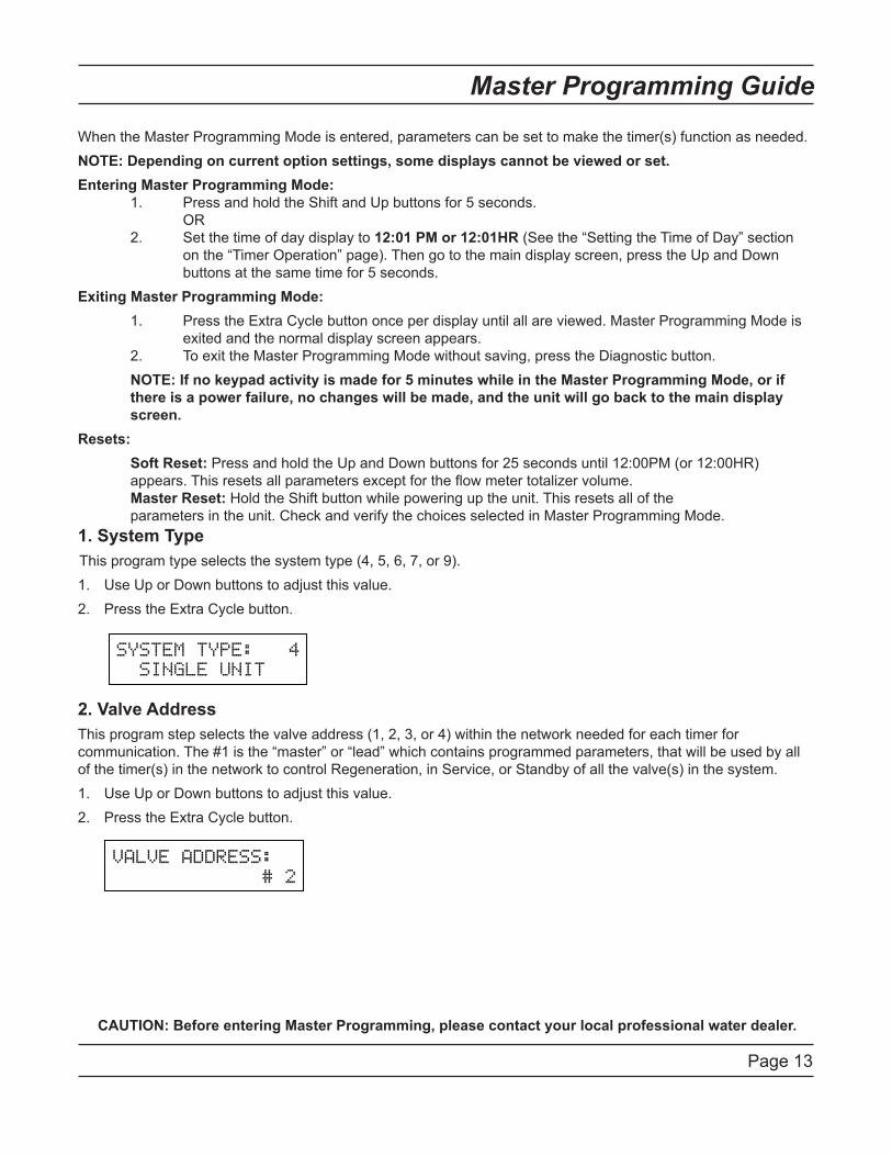
When the Master Programming Mode is entered, parameters can be set to make the timer(s) function as needed. NOTE: Depending on current option settings, some displays cannot be viewed or set. Entering Master Programming Mode: 1. Press and hold the Shift and Up buttons for 5 seconds. . . OR 2. Set the time of day display to 12:01 PM or 12:01HR (See the “Setting the Time of Day” section. on the “Timer Operation” page). Then go to the main display screen, press the Up and Down. buttons at the same time for 5 seconds. Exiting Master Programming Mode: 1. Press the Extra Cycle button once per display until all are viewed. Master Programming Mode is. exited and the normal display screen appears. 2. To exit the Master Programming Mode without saving, press the Diagnostic button.. NOTE: If no keypad activity is made for 5 minutes while in the Master Programming Mode, or if there is a power failure, no changes will be made, and the unit will go back to the main display screen.Resets:. Soft Reset: Press and hold the Up and Down buttons for 25 seconds until 12:00PM (or 12:00HR). appears. This resets all parameters except for the flow meter totalizer volume... Master Reset: Hold the Shift button while powering up the unit. This resets all of the. parameters in the unit. Check and verify the choices selected in Master Programming Mode.1. System TypeThis program type selects the system type (4, 5, �, 7, or 9).
Use Up or Down buttons to adjust this value.Press the Extra Cycle button.....
2. Valve AddressThis program step selects the valve address (1, 2, 3, or 4) within the network needed for each timer for communication. The #1 is the “master” or “lead” which contains programmed parameters, that will be used by all of the timer(s) in the network to control Regeneration, in Service, or Standby of all the valve(s) in the system.
Use Up or Down buttons to adjust this value.Press the Extra Cycle button.....
1.2.
1.2.
CAUTION: Before entering Master Programming, please contact your local professional water dealer.
Page 14
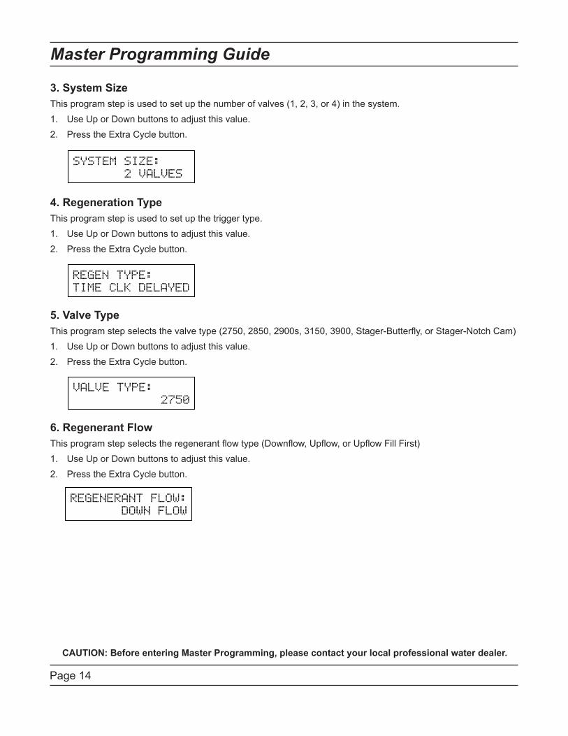
3. System SizeThis program step is used to set up the number of valves (1, 2, 3, or 4) in the system.
Use Up or Down buttons to adjust this value.Press the Extra Cycle button. ..
4. Regeneration TypeThis program step is used to set up the trigger type.
Use Up or Down buttons to adjust this value.Press the Extra Cycle button.
.
. 5. Valve TypeThis program step selects the valve type (2750, 2850, 2900s, 3150, 3900, Stager-Butterfly, or Stager-Notch Cam)
Use Up or Down buttons to adjust this value.Press the Extra Cycle button.
.
.
.
6. Regenerant FlowThis program step selects the regenerant flow type (Downflow, Upflow, or Upflow Fill First)
Use Up or Down buttons to adjust this value.Press the Extra Cycle button. .
.
.
.
1.2.
1.2.
1.2.
1.2.
Master Programming Guide
CAUTION: Before entering Master Programming, please contact your local professional water dealer.
Page 15
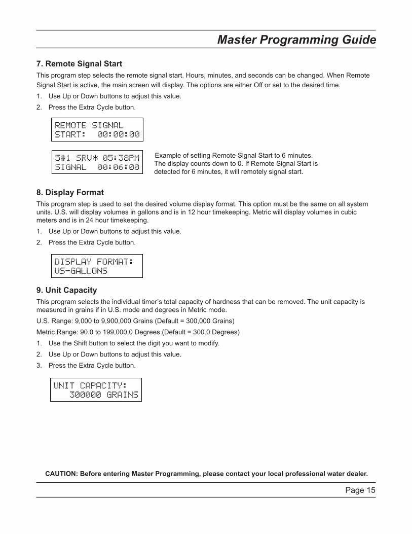
7. Remote Signal StartThis program step selects the remote signal start. Hours, minutes, and seconds can be changed. When Remote Signal Start is active, the main screen will display. The options are either Off or set to the desired time.
Use Up or Down buttons to adjust this value.Press the Extra Cycle button..
.
.
.
.
.
.
.
.8. Display FormatThis program step is used to set the desired volume display format. This option must be the same on all system units. U.S. will display volumes in gallons and is in 12 hour timekeeping. Metric will display volumes in cubic meters and is in 24 hour timekeeping.
Use Up or Down buttons to adjust this value.Press the Extra Cycle button.
.
.
.9. Unit CapacityThis program selects the individual timer’s total capacity of hardness that can be removed. The unit capacity is measured in grains if in U.S. mode and degrees in Metric mode.U.S. Range: 9,000 to 9,900,000 Grains (Default = 300,000 Grains)Metric Range: 90.0 to 199,000.0 Degrees (Default = 300.0 Degrees)
Use the Shift button to select the digit you want to modify.Use Up or Down buttons to adjust this value.Press the Extra Cycle button.
.
1.2.
1.2.
1.2.3.
Master Programming Guide
CAUTION: Before entering Master Programming, please contact your local professional water dealer.
Example of setting Remote Signal Start to � minutes. The display counts down to 0. If Remote Signal Start is detected for � minutes, it will remotely signal start.
Page 1�
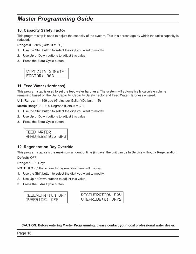
10. Capacity Safety FactorThis program step is used to adjust the capacity of the system. This is a percentage by which the unit’s capacity is reduced.Range: 0 – 50% (Default = 0%)
Use the Shift button to select the digit you want to modify.Use Up or Down buttons to adjust this value.Press the Extra Cycle button.
.
.
.
.
.11. Feed Water (Hardness)This program step is used to set the feed water hardness. The system will automatically calculate volume remaining based on the Unit Capacity, Capacity Safety Factor and Feed Water Hardness entered.U.S. Range: 1 – 199 gpg (Grains per Gallon)(Default = 15)Metric Range: 2 – 199 Degrees (Default = 30)
Use the Shift button to select the digit you want to modify.Use Up or Down buttons to adjust this value.Press the Extra Cycle button.
.
.
.
.
.12. Regeneration Day OverrideThis program step sets the maximum amount of time (in days) the unit can be In Service without a Regeneration.Default: OFFRange: 1 - 99 DaysNOTE: If “On,” the screen for regeneration time will display.
Use the Shift button to select the digit you want to modify.Use Up or Down buttons to adjust this value.Press the Extra Cycle button.
1.2.3.
1.2.3.
1.2.3.
Master Programming Guide
CAUTION: Before entering Master Programming, please contact your local professional water dealer.
Page 17
Master Programming Guide
.....
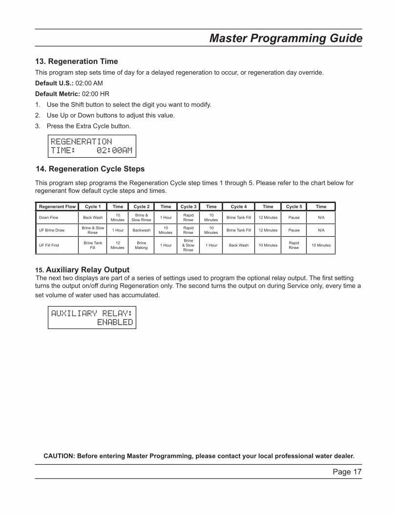
13. Regeneration TimeThis program step sets time of day for a delayed regeneration to occur, or regeneration day override.Default U.S.: 02:00 AMDefault Metric: 02:00 HR
Use the Shift button to select the digit you want to modify.Use Up or Down buttons to adjust this value.Press the Extra Cycle button.
14. Regeneration Cycle Steps
This program step programs the Regeneration Cycle step times 1 through 5. Please refer to the chart below for regenerant flow default cycle steps and times... 15. Auxiliary Relay OutputThe next two displays are part of a series of settings used to program the optional relay output. The first setting turns the output on/off during Regeneration only. The second turns the output on during Service only, every time a set volume of water used has accumulated.
1.2.3.
CAUTION: Before entering Master Programming, please contact your local professional water dealer.
Regenerant Flow Cycle 1 Time Cycle 2 Time Cycle 3 Time Cycle 4 Time Cycle 5 Time
Down Flow Back Wash 10.Minutes
Brine & Slow Rinse 1 Hour Rapid
Rinse10.
Minutes Brine Tank Fill 12 Minutes Pause N/A
UF Brine Draw Brine & Slow Rinse 1 Hour Backwash 10.
MinutesRapid Rinse
10.Minutes Brine Tank Fill 12 Minutes Pause N/A
UF Fill First Brine Tank Fill
12.Minutes
Brine Making 1 Hour
Brine & Slow Rinse
1 Hour Back Wash 10 Minutes Rapid Rinse 10 Minutes
Page 18
Master Programming Guide
CAUTION: Before entering Master Programming, please contact your local professional water dealer.
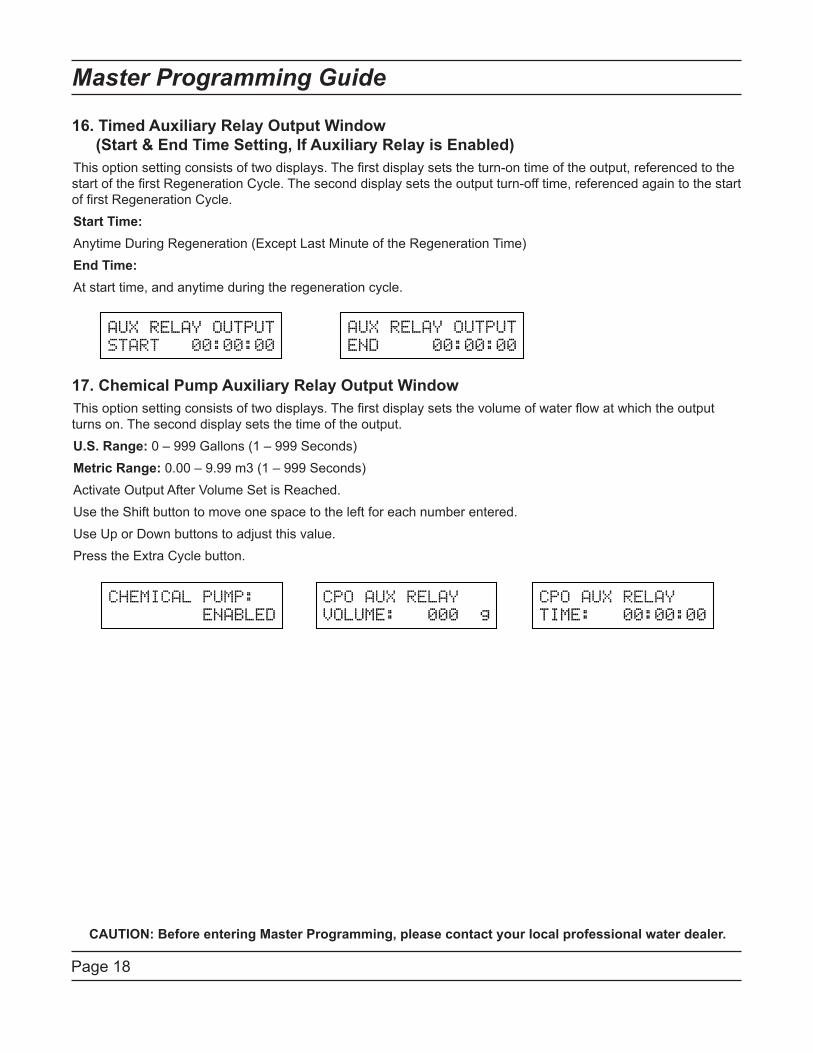
16. Timed Auxiliary Relay Output Window (Start & End Time Setting, If Auxiliary Relay is Enabled)This option setting consists of two displays. The first display sets the turn-on time of the output, referenced to the start of the first Regeneration Cycle. The second display sets the output turn-off time, referenced again to the start of first Regeneration Cycle.Start Time:Anytime During Regeneration (Except Last Minute of the Regeneration Time)End Time:At start time, and anytime during the regeneration cycle.......17. Chemical Pump Auxiliary Relay Output WindowThis option setting consists of two displays. The first display sets the volume of water flow at which the output turns on. The second display sets the time of the output.U.S. Range: 0 – 999 Gallons (1 – 999 Seconds)Metric Range: 0.00 – 9.99 m3 (1 – 999 Seconds)Activate Output After Volume Set is Reached.Use the Shift button to move one space to the left for each number entered.Use Up or Down buttons to adjust this value.Press the Extra Cycle button......
Page 19
Master Programming Guide
CAUTION: Before entering Master Programming, please contact your local professional water dealer.
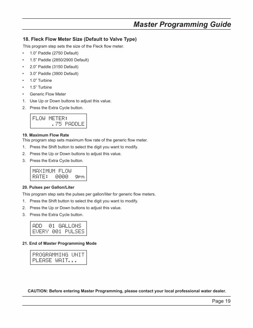
18. Fleck Flow Meter Size (Default to Valve Type)This program step sets the size of the Fleck flow meter.
1.0” Paddle (2750 Default)1.5” Paddle (2850/2900 Default)2.0” Paddle (3150 Default)3.0” Paddle (3900 Default)1.0” Turbine1.5” TurbineGeneric Flow MeterUse Up or Down buttons to adjust this value.Press the Extra Cycle button..
19. Maximum Flow Rate This program step sets maximum flow rate of the generic flow meter.
Press the Shift button to select the digit you want to modify.Press the Up or Down buttons to adjust this value.Press the Extra Cycle button.....
20. Pulses per Gallon/LiterThis program step sets the pulses per gallon/liter for generic flow meters.
Press the Shift button to select the digit you want to modify.Press the Up or Down buttons to adjust this value.Press the Extra Cycle button......
21. End of Master Programming Mode
•••••••1.2.
1.2.3.
1.2.3.
Page 20
User Mode Programming Flow Chart
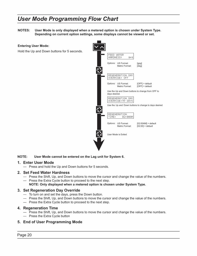
NOTES: User Mode is only displayed when a metered option is chosen under System Type. Depending on current option settings, some displays cannot be viewed or set.
Entering User Mode:Hold the Up and Down buttons for 5 seconds.
FEED WATERHARDNESS: gpg
REGENERATION DAYOVERRIDE: OFF
REGENERATION DAYOVERRIDE:99 DAYS
REGENERATIONTIME: 02:00AM
NOTE: User Mode cannot be entered on the Lag unit for System 6.
Enter User Mode — Press and hold the Up and Down buttons for 5 seconds.
Set Feed Water Hardness — Press the Shift, Up, and Down buttons to move the cursor and change the value of the numbers..— Press the Extra Cycle button to proceed to the next step... NOTE: Only displayed when a metered option is chosen under System Type.
Set Regeneration Day Override — To turn on and set the days, press the Down button..— Press the Shift, Up, and Down buttons to move the cursor and change the value of the numbers..— Press the Extra Cycle button to proceed to the next step.
Regeneration Time — Press the Shift, Up, and Down buttons to move the cursor and change the value of the numbers..— Press the Extra Cycle button
End of User Programming Mode
1.
2.
3.
4.
5.
Page 21
Diagnostic Mode Flow Chart
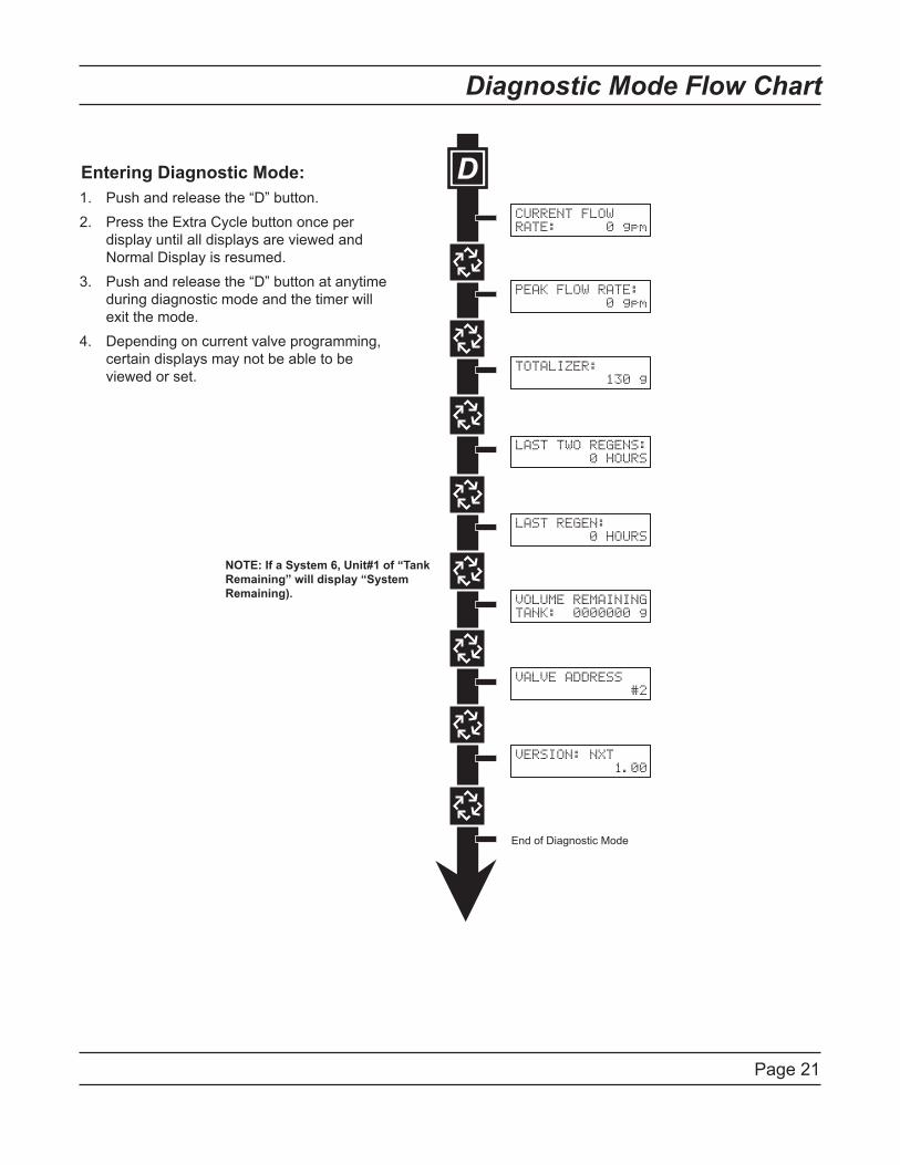
Entering Diagnostic Mode:Push and release the “D” button.Press the Extra Cycle button once per display until all displays are viewed and Normal Display is resumed.Push and release the “D” button at anytime during diagnostic mode and the timer will exit the mode.Depending on current valve programming, certain displays may not be able to be viewed or set.
1.2.
3.
4.
CURRENT FLOWRATE: 0 gpm
PEAK FLOW RATE: 0 gpm
TOTALIZER: 130 g
LAST TWO REGENS: 0 HOURS
LAST REGEN: 0 HOURS
VOLUME REMAININGTANK: 0000000 g
VALVE ADDRESS #2
VERSION: NXT 1.00
NOTE: If a System 6, Unit#1 of “TankRemaining” will display “SystemRemaining).
Page 22
Diagnostic Programming Guide
When the Diagnostics Mode is entered, all available displays are viewed as needed. Depending on current option settings, some displays cannot be viewed.
Overview Diagnostic ModeThe current diagnostic will be displayed until Extra Cycle key is pressed. There is no time limit on each display. The timer will display individual valve information, not system information. In the event of regeneration occurring while displaying diagnostics, the regeneration step and time remaining will be displayed. When regeneration has been completed, the display will return to the normal Time of Day display.
Entering and Exiting Diagnostic ModePush and Release the “D” button to enter. Pressing the Extra Cycle button will move to the next diagnostic to be displayed. Push the Extra Cycle button once per display until all are viewed. Pressing the Diagnostic button, while in the Diagnostic Mode, will cause the unit to leave the Diagnostic Mode and return to the normal time of day display.
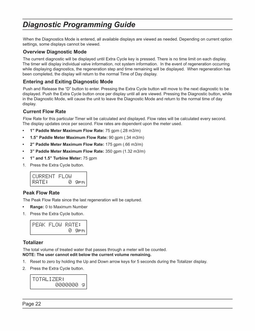
Current Flow RateFlow Rate for this particular Timer will be calculated and displayed. Flow rates will be calculated every second. The display updates once per second. Flow rates are dependent upon the meter used.
1” Paddle Meter Maximum Flow Rate: 75 gpm (.28 m3/m)1.5” Paddle Meter Maximum Flow Rate: 90 gpm (.34 m3/m)2” Paddle Meter Maximum Flow Rate: 175 gpm (.�� m3/m)3” Paddle Meter Maximum Flow Rate: 350 gpm (1.32 m3/m)1” and 1.5” Turbine Meter: 75 gpmPress the Extra Cycle button.....
Peak Flow RateThe Peak Flow Rate since the last regeneration will be captured.
Range: 0 to Maximum NumberPress the Extra Cycle button.....
TotalizerThe total volume of treated water that passes through a meter will be counted. .NOTE: The user cannot edit below the current volume remaining.
Reset to zero by holding the Up and Down arrow keys for 5 seconds during the Totalizer display. Press the Extra Cycle button.....
•••••1.
•1.
1.2.
Page 23
Diagnostic Programming Guide
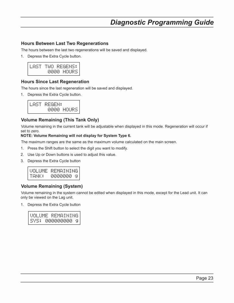
Hours Between Last Two RegenerationsThe hours between the last two regenerations will be saved and displayed.
Depress the Extra Cycle button.....
Hours Since Last RegenerationThe hours since the last regeneration will be saved and displayed.
Depress the Extra Cycle button.....
Volume Remaining (This Tank Only)Volume remaining in the current tank will be adjustable when displayed in this mode. Regeneration will occur if set to zero..NOTE: Volume Remaining will not display for System Type 6.The maximum ranges are the same as the maximum volume calculated on the main screen.
Press the Shift button to select the digit you want to modify.Use Up or Down buttons is used to adjust this value.Depress the Extra Cycle button....
Volume Remaining (System)Volume remaining in the system cannot be edited when displayed in this mode, except for the Lead unit. It can only be viewed on the Lag unit.
Depress the Extra Cycle button
1.
1.
1.2.3.
1.
Page 24
Diagnostic Programming Guide
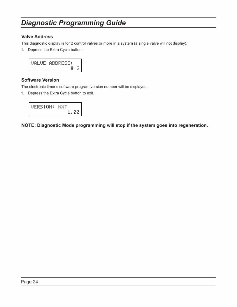
Valve AddressThis diagnostic display is for 2 control valves or more in a system (a single valve will not display).
Depress the Extra Cycle button......
Software VersionThe electronic timer’s software program version number will be displayed.
Depress the Extra Cycle button to exit.......
NOTE: Diagnostic Mode programming will stop if the system goes into regeneration.
1.
1.

Page 25
Notes
Page 2�
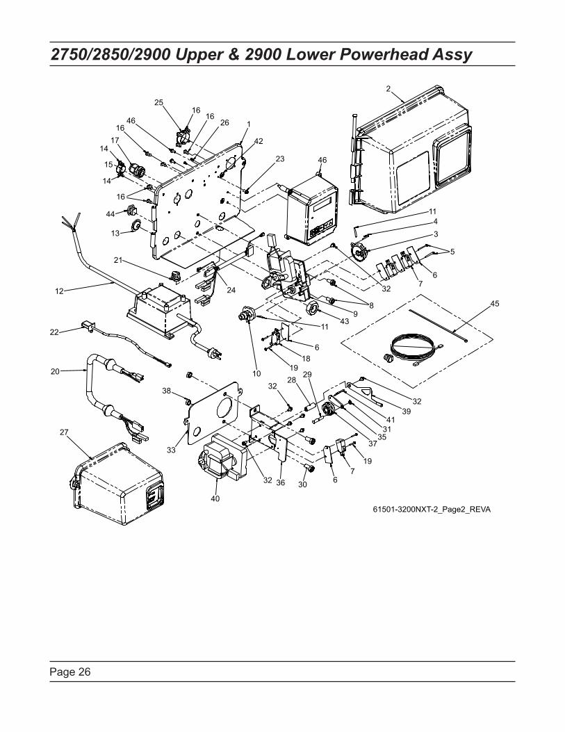
2750/2850/2900 Upper & 2900 Lower Powerhead Assy
3735
3141
3932
197
6303632
40
27
20
38
33
22
12
21
13
44
16
14
15
1417
1646
2516
1626 1
42
23 46
2
1143
5
67
45
1019
3228
29
186
1143
98
3224
61501-3200NXT-2_Page2_REVA
Page 27
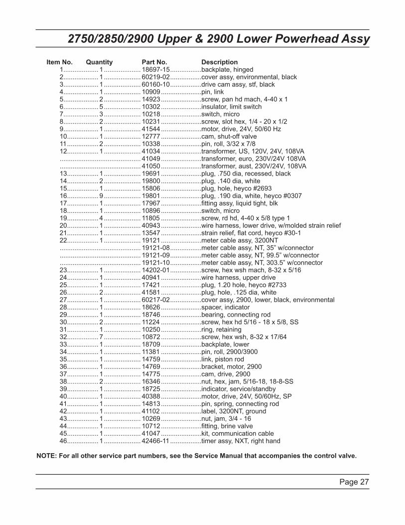
2750/2850/2900 Upper & 2900 Lower Powerhead Assy
Item No. Quantity Part No. Description. 1.................... 1..................... 18�97-15..................backplate, hinged. 2.................... 1..................... �0219-02..................cover assy, environmental, black. 3.................... 1..................... �01�0-10..................drive cam assy, stf, black. 4.................... 1..................... 10909.......................pin, link. 5.................... 2..................... 14923.......................screw, pan hd mach, 4-40 x 1. 6.................... 5..................... 10302.......................insulator, limit switch. 7.................... 3..................... 10218.......................switch, micro. 8.................... 2..................... 10231.......................screw, slot hex, 1/4 - 20 x 1/2. 9.................... 1..................... 41544.......................motor, drive, 24V, 50/�0 Hz. 10.................. 1..................... 12777.......................cam, shut-off valve. 11.................. 2..................... 10338.......................pin, roll, 3/32 x 7/8. 12.................. 1..................... 41034.......................transformer, US, 120V, 24V, 108VA. ............................................. 41049.......................transformer, euro, 230V/24V 108VA. ............................................. 41050.......................transformer, aust, 230V/24V, 108VA. 13.................. 1..................... 19691.......................plug, .750 dia, recessed, black. 14.................. 2..................... 19800.......................plug, .140 dia, white. 15.................. 1..................... 15806.......................plug, hole, heyco #2�93. 16.................. 9..................... 19801.......................plug, .190 dia, white, heyco #0307. 17.................. 1..................... 17967.......................fitting assy, liquid tight, blk. 18.................. 1..................... 10896.......................switch, micro. 19.................. 4..................... 11805.......................screw, rd hd, 4-40 x 5/8 type 1. 20.................. 1..................... 40943.......................wire harness, lower drive, w/molded strain relief. 21.................. 1..................... 13547.......................strain relief, flat cord, heyco #30-1. 22.................. 1..................... 19121.......................meter cable assy, 3200NT. ............................................. 19121-08..................meter cable assy, NT, 35” w/connector. ............................................. 19121-09..................meter cable assy, NT, 99.5” w/connector. ............................................. 19121-10..................meter cable assy, NT, 303.5” w/connector. 23.................. 1..................... 14202-01..................screw, hex wsh mach, 8-32 x 5/1�. 24.................. 1..................... 40941.......................wire harness, upper drive. 25.................. 1..................... 17421.......................plug, 1.20 hole, heyco #2733. 26.................. 2..................... 41581.......................plug, hole, .125 dia, white. 27.................. 1..................... �0217-02..................cover assy, 2900, lower, black, environmental. 28.................. 1..................... 18626.......................spacer, indicator. 29.................. 1..................... 18746.......................bearing, connecting rod. 30.................. 2..................... 11224.......................screw, hex hd 5/1� - 18 x 5/8, SS. 31.................. 1..................... 10250.......................ring, retaining. 32.................. 7..................... 10872.......................screw, hex wsh, 8-32 x 17/�4. 33.................. 1..................... 18709.......................backplate, lower. 34.................. 1..................... 11381.......................pin, roll, 2900/3900. 35.................. 1..................... 14759.......................link, piston rod. 36.................. 1..................... 14769.......................bracket, motor, 2900. 37.................. 1..................... 14775.......................cam, drive, 2900. 38.................. 2..................... 16346.......................nut, hex, jam, 5/1�-18, 18-8-SS. 39.................. 1..................... 18725.......................indicator, service/standby. 40.................. 1..................... 40388.......................motor, drive, 24V, 50/�0Hz, SP. 41.................. 1..................... 14813.......................pin, spring, connecting rod. 42.................. 1..................... 41102.......................label, 3200NT, ground. 43.................. 1..................... 10269.......................nut, jam, 3/4 - 1�. 44.................. 1..................... 10712.......................fitting, brine valve. 45.................. 1..................... 41047.......................kit, communication cable . 46.................. 1..................... 424��-11..................timer assy, NXT, right hand
NOTE: For all other service part numbers, see the Service Manual that accompanies the control valve.
Page 28
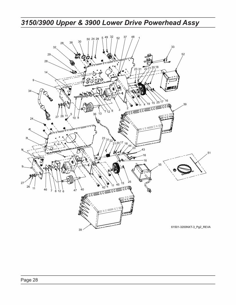
3150/3900 Upper & 3900 Lower Drive Powerhead Assy
5 1
4
3 267
5
14
9
41
13
39
2726 11 46 7 8 12 6 47 40
42 4 11 45 15 25
35
51
16
16
432344
18172021223123
27 26 1110 8
36 1312
11 19 15 25 17 1639
24
34
9
14
28
29
3228 38 30
50 24 28 49 32 52 37 48
23 31 22 21 20 18
33
52
61501-3200NXT-3_Pg2_REVA
Page 29
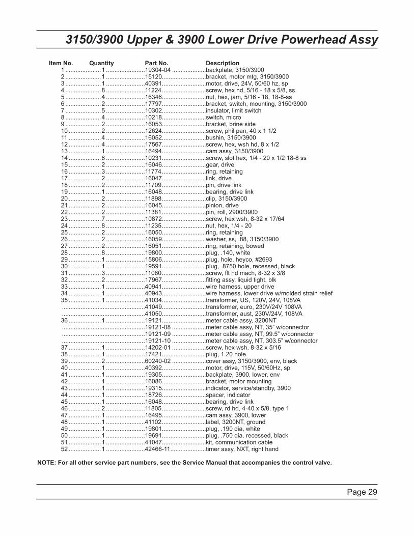
3150/3900 Upper & 3900 Lower Drive Powerhead Assy
Item No. Quantity Part No. Description. 1......................1........................19304-04.....................backplate, 3150/3900. 2......................1........................15120...........................bracket, motor mtg, 3150/3900. 3......................1........................40391...........................motor, drive, 24V, 50/�0 hz, sp. 4......................8........................11224...........................screw, hex hd, 5/1� - 18 x 5/8, ss. 5......................4........................16346...........................nut, hex, jam, 5/1� - 18, 18-8-ss. 6......................2........................17797...........................bracket, switch, mounting, 3150/3900. 7......................5........................10302...........................insulator, limit switch. 8......................4........................10218...........................switch, micro. 9......................2........................16053...........................bracket, brine side. 10....................2........................12624...........................screw, phil pan, 40 x 1 1/2. 11....................4........................16052...........................bushin, 3150/3900. 12....................4........................17567...........................screw, hex, wsh hd, 8 x 1/2. 13....................1........................16494...........................cam assy, 3150/3900. 14....................8........................10231...........................screw, slot hex, 1/4 - 20 x 1/2 18-8 ss. 15....................2........................16046...........................gear, drive. 16....................3........................11774...........................ring, retaining. 17....................2........................16047...........................link, drive. 18....................2........................11709...........................pin, drive link. 19....................1........................16048...........................bearing, drive link. 20....................2........................11898...........................clip, 3150/3900. 21....................2........................16045...........................pinion, drive. 22....................2........................11381...........................pin, roll, 2900/3900. 23....................7........................10872...........................screw, hex wsh, 8-32 x 17/�4. 24....................8........................11235...........................nut, hex, 1/4 - 20. 25....................2........................16050...........................ring, retaining. 26....................2........................16059...........................washer, ss, .88, 3150/3900. 27....................2........................16051...........................ring, retaining, bowed. 28....................8........................19800...........................plug, .140, white. 29....................1........................15806...........................plug, hole, heyco, #2�93. 30....................1........................19591...........................plug, .8750 hole, recessed, black. 31....................3........................11080...........................screw, flt hd mach, 8-32 x 3/8. 32....................2........................17967...........................fitting assy, liquid tight, blk. 33....................1........................40941...........................wire harness, upper drive. 34....................1........................40943...........................wire harness, lower drive w/molded strain relief. 35....................1........................41034...........................transformer, US, 120V, 24V, 108VA. ..................................................41049...........................transformer, euro, 230V/24V 108VA. ..................................................41050...........................transformer, aust, 230V/24V, 108VA. 36....................1........................19121...........................meter cable assy, 3200NT. ..................................................19121-08.....................meter cable assy, NT, 35” w/connector. ..................................................19121-09.....................meter cable assy, NT, 99.5” w/connector. ..................................................19121-10.....................meter cable assy, NT, 303.5” w/connector. 37....................1........................14202-01.....................screw, hex wsh, 8-32 x 5/1�. 38....................1........................17421...........................plug, 1.20 hole. 39....................2........................�0240-02.....................cover assy, 3150/3900, env, black. 40....................1........................40392...........................motor, drive, 115V, 50/�0Hz, sp. 41....................1........................19305...........................backplate, 3900, lower, env. 42....................1........................16086...........................bracket, motor mounting. 43....................1........................19315...........................indicator, service/standby, 3900. 44....................1........................18726...........................spacer, indicator. 45....................1........................16048...........................bearing, drive link. 46....................2........................11805...........................screw, rd hd, 4-40 x 5/8, type 1. 47....................1........................16495...........................cam assy, 3900, lower. 48....................1........................41102...........................label, 3200NT, ground. 49....................1........................19801...........................plug, .190 dia, white. 50....................1........................19691...........................plug, .750 dia, recessed, black. 51....................1........................41047...........................kit, communication cable. 52....................1........................424��-11......................timer assy, NXT, right hand
NOTE: For all other service part numbers, see the Service Manual that accompanies the control valve.
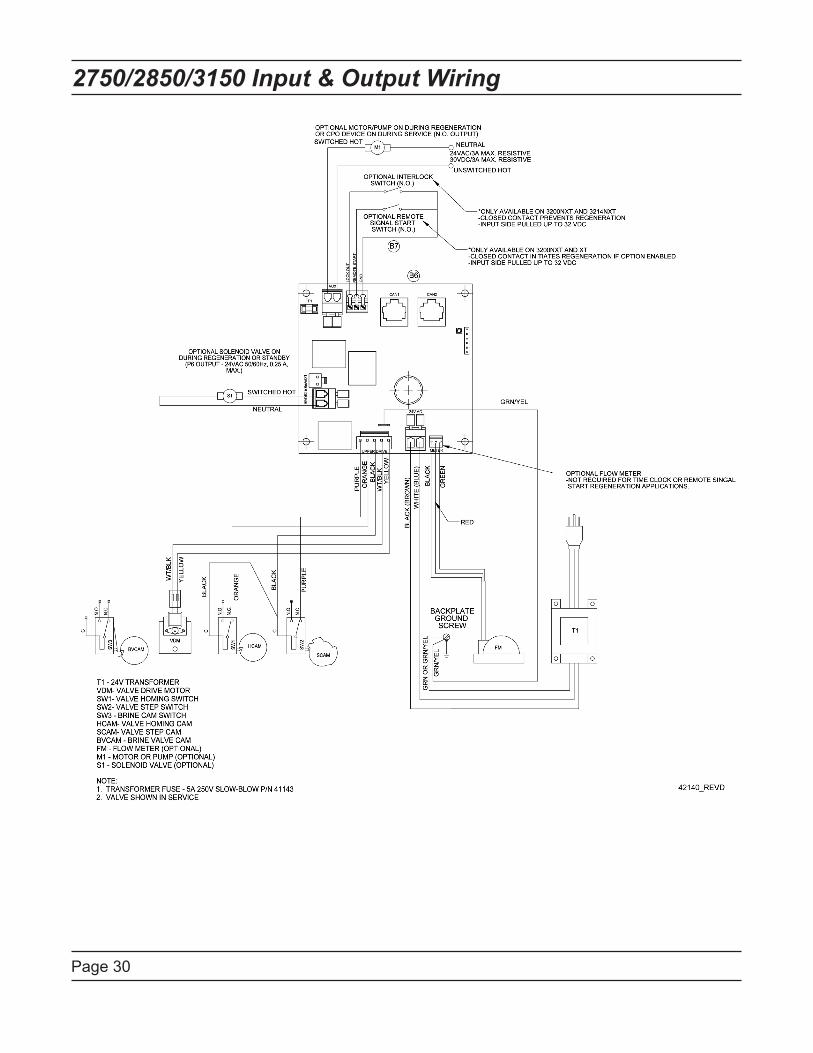
Page 30
2750/2850/3150 Input & Output Wiring
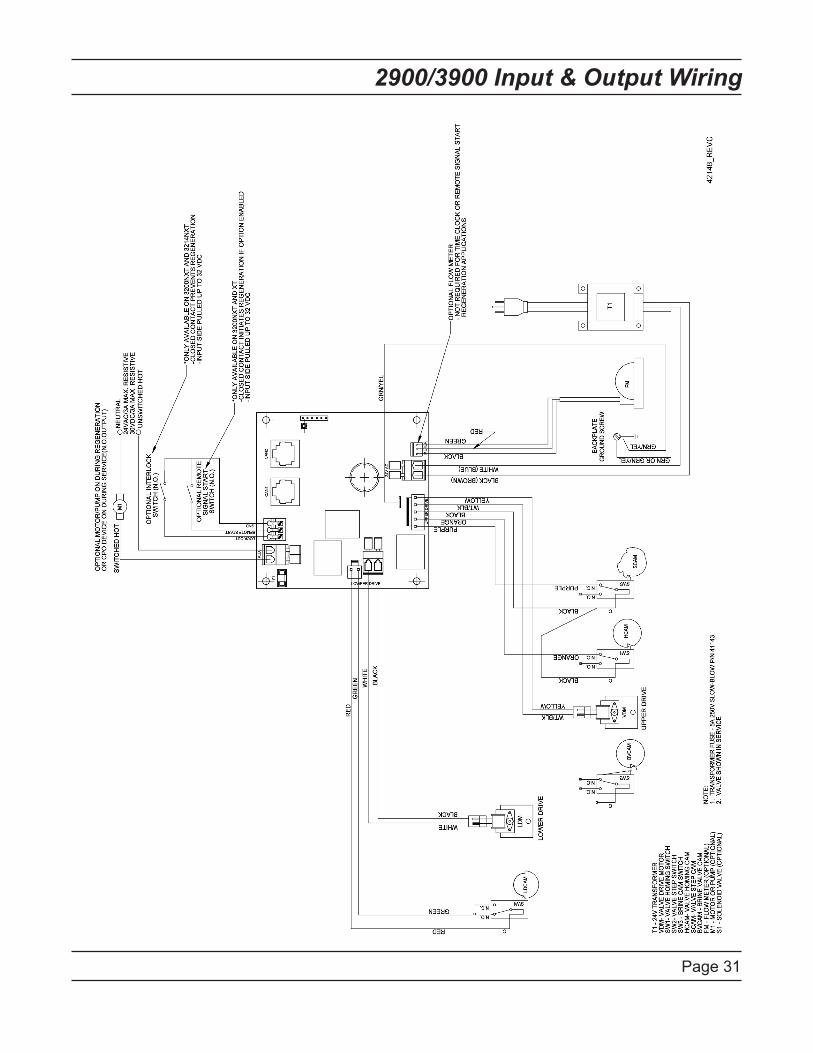
Page 31
2900/3900 Input & Output Wiring
Page 32
Troubleshooting
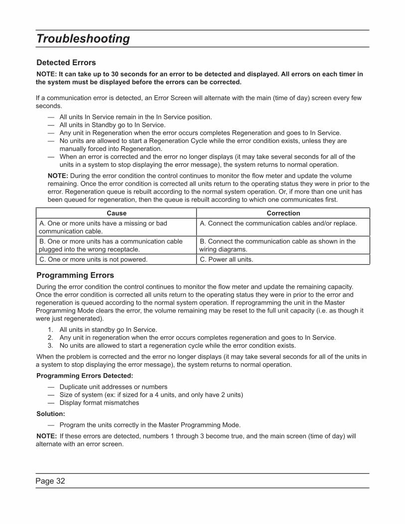
Detected ErrorsNOTE: It can take up to 30 seconds for an error to be detected and displayed. All errors on each timer in the system must be displayed before the errors can be corrected...If a communication error is detected, an Error Screen will alternate with the main (time of day) screen every few seconds.
— All units In Service remain in the In Service position. — All units in Standby go to In Service. — Any unit in Regeneration when the error occurs completes Regeneration and goes to In Service. — No units are allowed to start a Regeneration Cycle while the error condition exists, unless they are manually forced into Regeneration. — When an error is corrected and the error no longer displays (it may take several seconds for all of the units in a system to stop displaying the error message), the system returns to normal operation.
NOTE: During the error condition the control continues to monitor the flow meter and update the volume remaining. Once the error condition is corrected all units return to the operating status they were in prior to the error. Regeneration queue is rebuilt according to the normal system operation. Or, if more than one unit has been queued for regeneration, then the queue is rebuilt according to which one communicates first.
Cause CorrectionA. One or more units have a missing or bad communication cable.
A. Connect the communication cables and/or replace.
B. One or more units has a communication cable plugged into the wrong receptacle.
B. Connect the communication cable as shown in the wiring diagrams.
C. One or more units is not powered. C. Power all units.
Programming ErrorsDuring the error condition the control continues to monitor the flow meter and update the remaining capacity. Once the error condition is corrected all units return to the operating status they were in prior to the error and regeneration is queued according to the normal system operation. If reprogramming the unit in the Master Programming Mode clears the error, the volume remaining may be reset to the full unit capacity (i.e. as though it were just regenerated).
1. All units in standby go In Service. 2. Any unit in regeneration when the error occurs completes regeneration and goes to In Service. 3. No units are allowed to start a regeneration cycle while the error condition exists.
When the problem is corrected and the error no longer displays (it may take several seconds for all of the units in a system to stop displaying the error message), the system returns to normal operation.
Programming Errors Detected: — Duplicate unit addresses or numbers — Size of system (ex: if sized for a 4 units, and only have 2 units) — Display format mismatches
Solution: — Program the units correctly in the Master Programming Mode.
NOTE: If these errors are detected, numbers 1 through 3 become true, and the main screen (time of day) will alternate with an error screen.
Page 33
Troubleshooting
Cause CorrectionA. Any or all of two or more units programmed with the same unit number (Matching Address Error)
A. Program the units correctly in the Master Programming Mode
B. Flashing/blinking display B. Power outage has occurredC. Format Mismatch (Units have both U.S. and Metric Formats)
C. Verify all units have same Format selected (all U.S. or all Metric)
D. No messages displayed/small black squares appear in display
D. Turn the contrast button on the back of unit until text appears (see “Problems Viewing Display/Changing Contrast of Display” below)
E. Size Error (Units not correctly numbered/more than one unit has the same number assigned)
E. Check each unit and verify each as the correct number, and that only one unit has that number
F. Com Error (Communication Error) F. Check the wiring of the system and verify it is correct and that all are connected
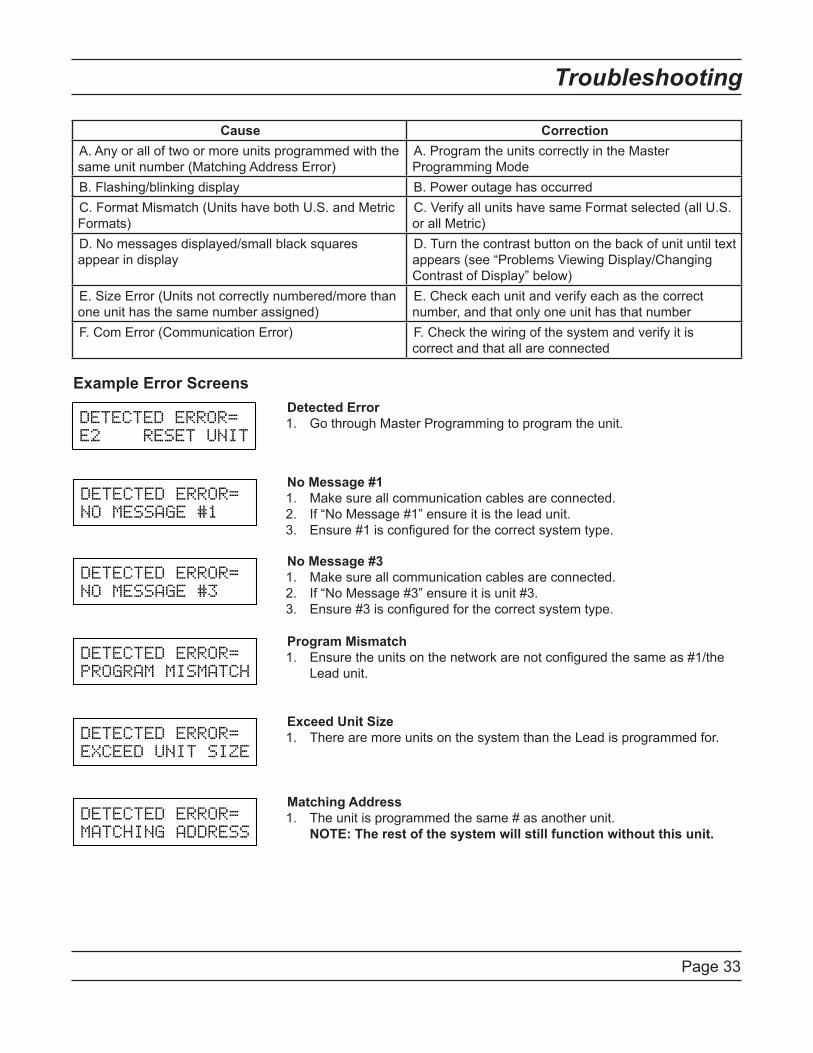
Example Error Screens
DETECTED ERROR=
E2 RESET UNIT
DETECTED ERROR=
NO MESSAGE #1
DETECTED ERROR=
NO MESSAGE #3
DETECTED ERROR=
PROGRAM MISMATCH
DETECTED ERROR=
EXCEED UNIT SIZE
DETECTED ERROR=
MATCHING ADDRESS
Detected ErrorGo through Master Programming to program the unit.1.
No Message #1Make sure all communication cables are connected.If “No Message #1” ensure it is the lead unit.Ensure #1 is configured for the correct system type.
1.2.3.
No Message #3Make sure all communication cables are connected.If “No Message #3” ensure it is unit #3.Ensure #3 is configured for the correct system type.
1.2.3.
Program MismatchEnsure the units on the network are not configured the same as #1/the Lead unit.
1.
Exceed Unit SizeThere are more units on the system than the Lead is programmed for.1.
Matching AddressThe unit is programmed the same # as another unit. .NOTE: The rest of the system will still function without this unit.
1.

Page 34
Notes

Page 35
Notes

P/N 42599 Rev. A 4/15/08