Embed Size (px)
Citation preview
Ferrari 4000Service Guide
PRINTED IN TAIWAN
Service guide files and updates are availableon the ACER/CSD web; for more information,
please refer to http://csd.acer.com.tw

Revision HistoryPlease refer to the table below for the updates made on Ferrari 4000 service guide.
Date Chapter Updates
II
CopyrightCopyright © 2005 by Acer Incorporated. All rights reserved. No part of this publication may be reproduced, transmitted, transcribed, stored in a retrieval system, or translated into any language or computer language, in any form or by any means, electronic, mechanical, magnetic, optical, chemical, manual or otherwise, without the prior written permission of Acer Incorporated.
DisclaimerThe information in this guide is subject to change without notice.
Acer Incorporated makes no representations or warranties, either expressed or implied, with respect to the contents hereof and specifically disclaims any warranties of merchantability or fitness for any particular purpose. Any Acer Incorporated software described in this manual is sold or licensed "as is". Should the programs prove defective following their purchase, the buyer (and not Acer Incorporated, its distributor, or its dealer) assumes the entire cost of all necessary servicing, repair, and any incidental or consequential damages resulting from any defect in the software.
Acer is a registered trademark of Acer Corporation.Intel is a registered trademark of Intel Corporation.Pentium and Pentium II/III are trademarks of Intel Corporation.Other brand and product names are trademarks and/or registered trademarks of their respective holders.
III
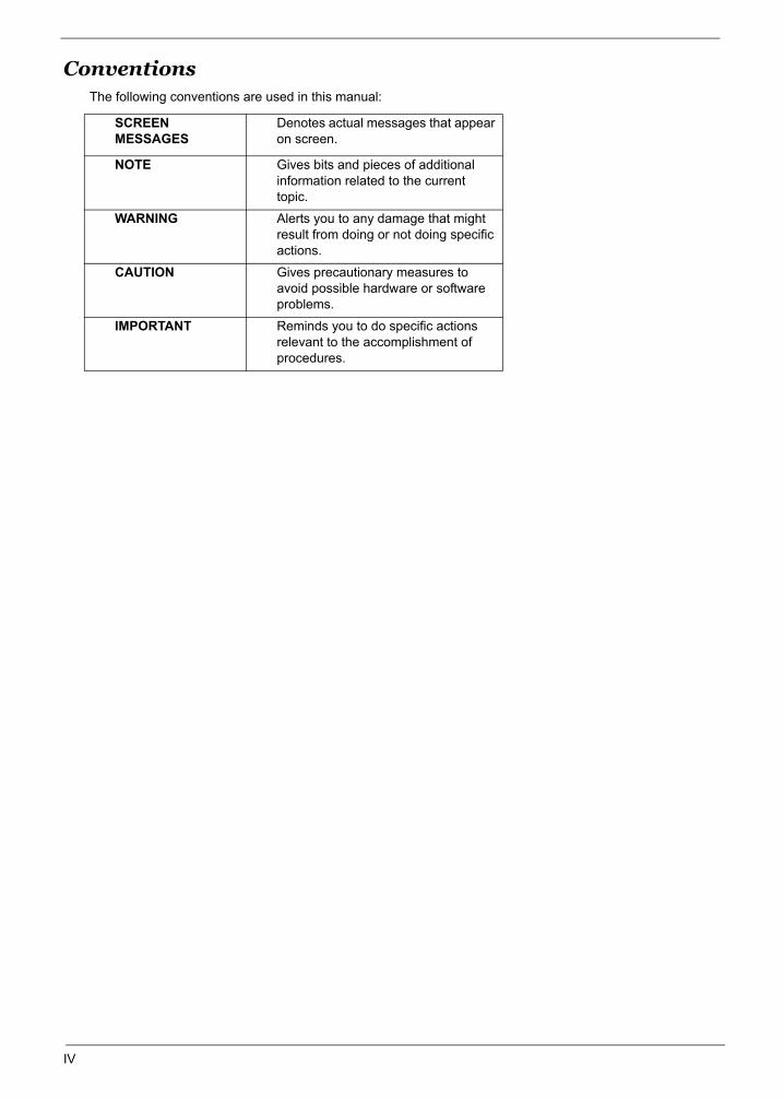
ConventionsThe following conventions are used in this manual:
SCREEN MESSAGES
Denotes actual messages that appear on screen.
NOTE Gives bits and pieces of additional information related to the current topic.
WARNING Alerts you to any damage that might result from doing or not doing specific actions.
CAUTION Gives precautionary measures to avoid possible hardware or software problems.
IMPORTANT Reminds you to do specific actions relevant to the accomplishment of procedures.
IV
PrefaceBefore using this information and the product it supports, please read the following general information.
1. This Service Guide provides you with all technical information relating to the BASIC CONFIGURATION decided for Acer's "global" product offering. To better fit local market requirements and enhance product competitiveness, your regional office MAY have decided to extend the functionality of a machine (e.g. add-on card, modem, or extra memory capability). These LOCALIZED FEATURES will NOT be covered in this generic service guide. In such cases, please contact your regional offices or the responsible personnel/channel to provide you with further technical details.
2. Please note WHEN ORDERING FRU PARTS, that you should check the most up-to-date information available on your regional web or channel. If, for whatever reason, a part number change is made, it will not be noted in the printed Service Guide. For ACER-AUTHORIZED SERVICE PROVIDERS, your Acer office may have a DIFFERENT part number code to those given in the FRU list of this printed Service Guide. You MUST use the list provided by your regional Acer office to order FRU parts for repair and service of customer machines.
V
Table of Contents
Chapter 1 System Specifications 1Overview . . . . . . . . . . . . . . . . . . . . . . . . . . . . . . . . . . . . . . . . . . . . . . . . . . . . . . . .1Features . . . . . . . . . . . . . . . . . . . . . . . . . . . . . . . . . . . . . . . . . . . . . . . . . . . . . . . .2Mainboard Placement . . . . . . . . . . . . . . . . . . . . . . . . . . . . . . . . . . . . . . . . . . . . . .5
Top View . . . . . . . . . . . . . . . . . . . . . . . . . . . . . . . . . . . . . . . . . . . . . . . . . . . .5Rear View . . . . . . . . . . . . . . . . . . . . . . . . . . . . . . . . . . . . . . . . . . . . . . . . . . .6Power Board . . . . . . . . . . . . . . . . . . . . . . . . . . . . . . . . . . . . . . . . . . . . . . . . .7
Block Diagram . . . . . . . . . . . . . . . . . . . . . . . . . . . . . . . . . . . . . . . . . . . . . . . . . . .8Outlook View . . . . . . . . . . . . . . . . . . . . . . . . . . . . . . . . . . . . . . . . . . . . . . . . . . . . .9
Open View . . . . . . . . . . . . . . . . . . . . . . . . . . . . . . . . . . . . . . . . . . . . . . . . . . .9Close Front View . . . . . . . . . . . . . . . . . . . . . . . . . . . . . . . . . . . . . . . . . . . . .10Left View . . . . . . . . . . . . . . . . . . . . . . . . . . . . . . . . . . . . . . . . . . . . . . . . . . .11Right View . . . . . . . . . . . . . . . . . . . . . . . . . . . . . . . . . . . . . . . . . . . . . . . . . .12Rear View . . . . . . . . . . . . . . . . . . . . . . . . . . . . . . . . . . . . . . . . . . . . . . . . . .13Bottom View. . . . . . . . . . . . . . . . . . . . . . . . . . . . . . . . . . . . . . . . . . . . . . . . .14
Using the Keyboard . . . . . . . . . . . . . . . . . . . . . . . . . . . . . . . . . . . . . . . . . . . . . .15Lock Keys . . . . . . . . . . . . . . . . . . . . . . . . . . . . . . . . . . . . . . . . . . . . . . . . . .15Embedded Numeric Keypad . . . . . . . . . . . . . . . . . . . . . . . . . . . . . . . . . . . .16Windows Key . . . . . . . . . . . . . . . . . . . . . . . . . . . . . . . . . . . . . . . . . . . . . . . .16Hot Keys . . . . . . . . . . . . . . . . . . . . . . . . . . . . . . . . . . . . . . . . . . . . . . . . . . .17Special Keys . . . . . . . . . . . . . . . . . . . . . . . . . . . . . . . . . . . . . . . . . . . . . . . .19
Indicators . . . . . . . . . . . . . . . . . . . . . . . . . . . . . . . . . . . . . . . . . . . . . . . . . . . . . . .20Launch Keys . . . . . . . . . . . . . . . . . . . . . . . . . . . . . . . . . . . . . . . . . . . . . . . .20Easy-launch Buttons . . . . . . . . . . . . . . . . . . . . . . . . . . . . . . . . . . . . . . . . . .21
Using the Bluetooth Wireless Optical Mouse. . . . . . . . . . . . . . . . . . . . . . . . . . . .22Installation . . . . . . . . . . . . . . . . . . . . . . . . . . . . . . . . . . . . . . . . . . . . . . . . . .22Usage. . . . . . . . . . . . . . . . . . . . . . . . . . . . . . . . . . . . . . . . . . . . . . . . . . . . . .22Recharging the Bluetooth Mouse. . . . . . . . . . . . . . . . . . . . . . . . . . . . . . . . .22
Using System Utilities . . . . . . . . . . . . . . . . . . . . . . . . . . . . . . . . . . . . . . . . . . . . .23Acer eManagement . . . . . . . . . . . . . . . . . . . . . . . . . . . . . . . . . . . . . . . . . . .23Acer GridVista . . . . . . . . . . . . . . . . . . . . . . . . . . . . . . . . . . . . . . . . . . . . . . .24Launch Manager . . . . . . . . . . . . . . . . . . . . . . . . . . . . . . . . . . . . . . . . . . . . .26
Audio . . . . . . . . . . . . . . . . . . . . . . . . . . . . . . . . . . . . . . . . . . . . . . . . . . . . . . . . . .27Touchpad. . . . . . . . . . . . . . . . . . . . . . . . . . . . . . . . . . . . . . . . . . . . . . . . . . . . . . .28Ejecting the optical (CD or DVD) drive tray . . . . . . . . . . . . . . . . . . . . . . . . . . . . .30Using a Computer Security Lock . . . . . . . . . . . . . . . . . . . . . . . . . . . . . . . . . . . . .31Hardware Specifications and Configurations. . . . . . . . . . . . . . . . . . . . . . . . . . . .32
Chapter 2 System Utilities 44
BIOS Setup Utility . . . . . . . . . . . . . . . . . . . . . . . . . . . . . . . . . . . . . . . . . . . . . . . .44Buttons. . . . . . . . . . . . . . . . . . . . . . . . . . . . . . . . . . . . . . . . . . . . . . . . . . . . . . . . .45
Application Launch Buttons . . . . . . . . . . . . . . . . . . . . . . . . . . . . . . . . . . . . .45Power Button . . . . . . . . . . . . . . . . . . . . . . . . . . . . . . . . . . . . . . . . . . . . . . . .45Lid Switch . . . . . . . . . . . . . . . . . . . . . . . . . . . . . . . . . . . . . . . . . . . . . . . . . .45Hardware Disk Password Function/Password on boot function . . . . . . . . .46Valid Password Characters . . . . . . . . . . . . . . . . . . . . . . . . . . . . . . . . . . . . .46
Information . . . . . . . . . . . . . . . . . . . . . . . . . . . . . . . . . . . . . . . . . . . . . . . . . . . . .47Main . . . . . . . . . . . . . . . . . . . . . . . . . . . . . . . . . . . . . . . . . . . . . . . . . . . . . . . . . . 48Advanced . . . . . . . . . . . . . . . . . . . . . . . . . . . . . . . . . . . . . . . . . . . . . . . . . . . . . .50Security . . . . . . . . . . . . . . . . . . . . . . . . . . . . . . . . . . . . . . . . . . . . . . . . . . . . . . . .52Boot . . . . . . . . . . . . . . . . . . . . . . . . . . . . . . . . . . . . . . . . . . . . . . . . . . . . . . . . . .54Exit . . . . . . . . . . . . . . . . . . . . . . . . . . . . . . . . . . . . . . . . . . . . . . . . . . . . . . . . . . .55
VII
Table of Contents
Chapter 3 Machine Disassembly 56General Information . . . . . . . . . . . . . . . . . . . . . . . . . . . . . . . . . . . . . . . . . . . . . .57Disassembly Procedure Flowchart . . . . . . . . . . . . . . . . . . . . . . . . . . . . . . . . . . .58Removing the Battery Pack . . . . . . . . . . . . . . . . . . . . . . . . . . . . . . . . . . . . . . . . .60Removing the HDD Module and mini PCI . . . . . . . . . . . . . . . . . . . . . . . . . . . . . .61
Removing the HDD Module . . . . . . . . . . . . . . . . . . . . . . . . . . . . . . . . . . . . .61Removing the Memory. . . . . . . . . . . . . . . . . . . . . . . . . . . . . . . . . . . . . . . . .61Removing the miniPCI . . . . . . . . . . . . . . . . . . . . . . . . . . . . . . . . . . . . . . . . .62
Disassembling the Main Unit into Upper Case and Lower Case . . . . . . . . . . . . .63Disassembling the Lower Case . . . . . . . . . . . . . . . . . . . . . . . . . . . . . . . . . . . . . .65Disassembling the LCD Module and Upper Case . . . . . . . . . . . . . . . . . . . . . . . .68Disassembling the LCD Moudle . . . . . . . . . . . . . . . . . . . . . . . . . . . . . . . . . . . . .71Disassembling the External Modules. . . . . . . . . . . . . . . . . . . . . . . . . . . . . . . . . .73
Chapter 4 Troubleshooting 74
System Check Procedures . . . . . . . . . . . . . . . . . . . . . . . . . . . . . . . . . . . . . . . . .75External Diskette Drive Check . . . . . . . . . . . . . . . . . . . . . . . . . . . . . . . . . .75External CD-ROM Drive Check . . . . . . . . . . . . . . . . . . . . . . . . . . . . . . . . .75Keyboard or Auxiliary Input Device Check . . . . . . . . . . . . . . . . . . . . . . . . .75Memory Check . . . . . . . . . . . . . . . . . . . . . . . . . . . . . . . . . . . . . . . . . . . . . .76Power System Check . . . . . . . . . . . . . . . . . . . . . . . . . . . . . . . . . . . . . . . . .76Check the Power Adapter . . . . . . . . . . . . . . . . . . . . . . . . . . . . . . . . . . . . . .76Check the Battery Pack . . . . . . . . . . . . . . . . . . . . . . . . . . . . . . . . . . . . . . . 78Touchpad Check . . . . . . . . . . . . . . . . . . . . . . . . . . . . . . . . . . . . . . . . . . . . 78
PhoenixBIOS POST Tasks and Beep Codes . . . . . . . . . . . . . . . . . . . . . . . . . . .79Index of Error Messages . . . . . . . . . . . . . . . . . . . . . . . . . . . . . . . . . . . . . . . . . . .80POST Code . . . . . . . . . . . . . . . . . . . . . . . . . . . . . . . . . . . . . . . . . . . . . . . . . . . . .83Index of Symptom-to-FRU Error Message . . . . . . . . . . . . . . . . . . . . . . . . . . . . .84Intermittent Problems. . . . . . . . . . . . . . . . . . . . . . . . . . . . . . . . . . . . . . . . . . . . . .87Undetermined Problems . . . . . . . . . . . . . . . . . . . . . . . . . . . . . . . . . . . . . . . . . . .88Use NAPP CD to Build Master Hard Disc Drive . . . . . . . . . . . . . . . . . . . . . . . . .89
Chpater 5 Jumper and Connector Locations 96
Top View . . . . . . . . . . . . . . . . . . . . . . . . . . . . . . . . . . . . . . . . . . . . . . . . . . . . . . .96Rear View . . . . . . . . . . . . . . . . . . . . . . . . . . . . . . . . . . . . . . . . . . . . . . . . . . . . . .97Remove BIOS Password . . . . . . . . . . . . . . . . . . . . . . . . . . . . . . . . . . . . . . . . . .98Remove HDD Password . . . . . . . . . . . . . . . . . . . . . . . . . . . . . . . . . . . . . . . . . . .99
Chapter 6 FRU (Field Replaceable Unit) List 101
Exploded Diagram . . . . . . . . . . . . . . . . . . . . . . . . . . . . . . . . . . . . . . . . . . . . . .102Parts . . . . . . . . . . . . . . . . . . . . . . . . . . . . . . . . . . . . . . . . . . . . . . . . . . . . . . . .106
Appendix A Model Definition and Configuration 114
Appendix B Test Compatible Components 115
Microsoft Windows XP(Home/Professional) Environment Test . . . . . . . . . . . .116
Appendix C Online Support Information 118
VIII
System Specifications
Chapter 1
OverviewFerrari series is designed with AMD’s top speed low power CPUs with the fantastic chassis. It adopts the 15.4”
LCD with the unique carbon fiber frame and coating.
The AMD Athlon 64 processor is the world’s most technically advanced processor for notebook computing and
the only Windows-compatible 64-bit PC processor for notebook computing. Advanced technologies in the
AMD Athlon 64 processor include:
AMD64 technology doubles the number of processor registers and dramatically increases the system memory addressability
Enhanced multimedia instructions support including 3DNow! Professional technology and SSE2
1600 MHz system bus using HyperTransport technology with up to 9.1 GB/sec total processor-to-system bandwidth
An integrated memory controller with peak memory bandwidth of 2.7 GB/sec, supporting PC2700, PC2100, or PC1600 DDR SDRAM
The industry’s largest cache memory system (1 Megabyte L2 cache) to speed up memory access and eliminate processor bottlenecks
Native execution of 32-bit software, allowing today’s PC software to run seamlessly, simplifying the migration to 64-bit software
Here itemize those key features as below :
15.4” wide WSXGA optimized
DDR 333
Current Kingfisher’s (TravelMate 8100) chassis with carbon fiber LCD cover
Two spindle solution
Acer New FineTouch ergo KBD
PCI-E
One Acer Empowering Button
Acer ezDock support
High quality speakers
Acer eManager
Optimized Performance and long battery life(LBL)
Parallel ATA support
Outstanding wireless performance (acer SignalUp)
New casing material and painting
Chapter 1 1
FeaturesThis computer was designed with the user in mind. Here are just a few of its many features:
Performance
AMD 35W, Mobile AMD TurionTM 64 ML30/34/37/40 processor (2.2GHz, 1MB cache)
Simultanceous 32 bit and 64 bit Windows® compatible support
Supporting AMD PowerNowTM :
Optimizes battery life
Provides performance on demand when required by the application
Allows the processor to dissipate less heat under normal operating conditions, providing a cooler and quieter-running notebook
Operates automatically in the background
Supporting AMD Hyper TransportTM
Provide significantly more bandwidth than current technologies
Use low-latency responses and low pin counts
Maintain compatibility with legacy PC buses while being extensible to new SNA (Systems Network Architecture) buses
Appear transparent to operating systems and offer little impact on peripheral drivers
Enhanced Virus Protection:
Prevent the spread of certain malicious viruses, which are transported via e-mail and instant messaging applications
Surf the Internet with confidence, knowing you have an extra level of protection against certain harmful web downloads
Help improve the integrity of your home and office network
Supporting 3DNowTM Professional Technology
Enable stellar performance and playback quality on digital entertainment features such as games, streaming video and audio, DVDs, and music
NOTE: Foresaid are some quoted from AMD website copyright.
Chipset : ATI RX480M,SB400
Memory
DDR333 SDRAM memory interface design
0MB DDR RAM on board
Two DDR SODIMM slots
Maximum memory up to 2GB (with two 1GB SODIMM)
Display15.4” WSXGA+ TFT LCD
1680x1050 pixel resolution, 16.7 million colors
Supporting simultaneous multi-windows viewing via Acer GridVista (http://www.acer.co.th/product/travelmate/AcerGridVista.htm)
2 Chapter 1
Chapter 1 3
Graphics
ATI MOBILITYTM RADEON® X700 with 128MB of video memory
Microsoft® DirectX® 9.0 support
ATI POWERPLAYTM 5.0 support
PCI ExpressTM support
DualViewTM support
External resolution/refresh rate
2048x1536: 60/66/70/75/78/85 Hz
1600x1200: 60/75/85/100/120 Hz
1280x1024: 60/70/75/85/90/100/120/160/180 Hz
1024x768: 60/70/72/75/85/90/100/120/150/160/200 Hz
800x600: 60/70/75/85/90/100/120/160/200 Hz
MPEG-2/DVD hardware-assisted capability
S-video/TV-out (NTSC/PAL) support
DVI-D support
Audio
16-bit AC’97 stereo audio
Internal Microphone
Two speakers high quality
S/PDIF support
Storage
Support PATA
9.5mm height, 2.5” HDD
PCI Bus Master Enhanced IDE
Support Ultra DMA100, S.M.A.R.T
Communication56Kbps V.92 AC-Link modem card (MDC)
Gigabit Ethernet, Wake-on-LAN already
WLAN 802.11b/g Wi-Fi CERTIFIEDTM solution; supporting Acer SignalUp wireless technology
Built-in 2 Antenna
Mini-PCI (option)
4 Chapter 1
I/O PortsOne VGA port, 15 pins
One Microphone
One Headphone/SPDIF
One S-Video port (TV-OUT)
Four External USB 2.0 connectors
One DC in jack at left-hand side
One RJ-11 jack for Modem
One RJ-45 jack for LAN
One IEEE1394 (4pin)
One FIR
One SPR (rear side, Acer proprietary ezDock)
5-in-1 card reader ( MS : Memory Stick
MS-Pro : Memory Stick Pro.
MMC : MultiMedia Card
SD : Security Digital
xD : xD-Picture Card
Battery
8-cell of Li-ion battery pack, (4800mAh,70W)
4-cell of Li-ion battery pack, (2200mAh,32W)
90W AC adaptor 19V 4.74A
Weight (with battery)
6.3 lbs (2.86 kg)
Dimensions
363(W) x 265.7(D) x 30.5/34.3(H) mm (14.29 x 10.46 x 1.2/1.36 inches)
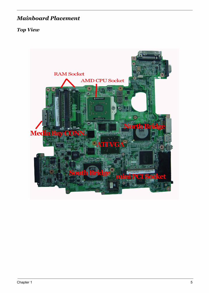
Mainboard Placement
Top View
Chapter 1 5
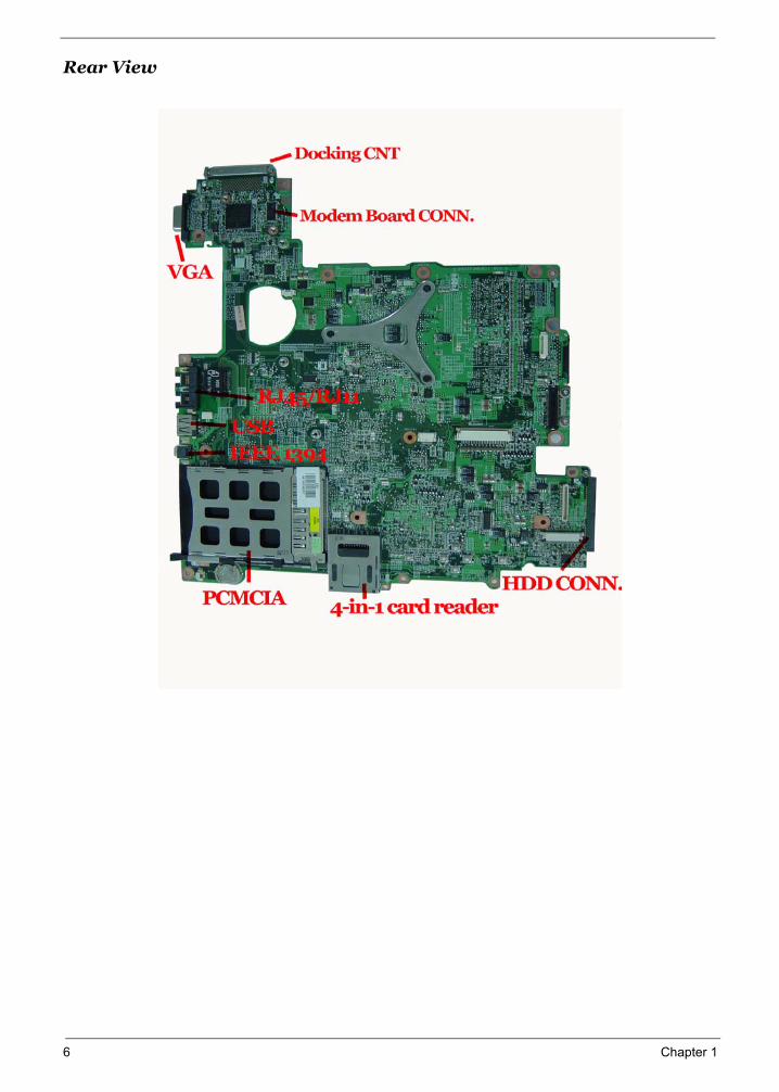
Rear View
6 Chapter 1
Chapter 1 7
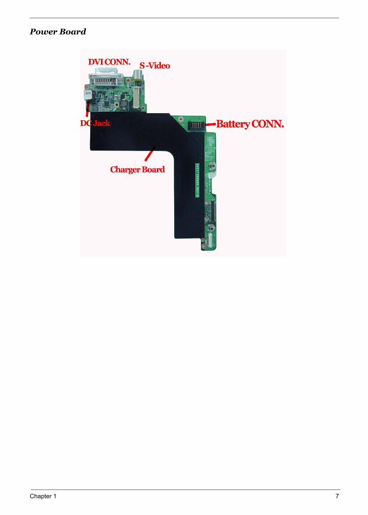
Power Board
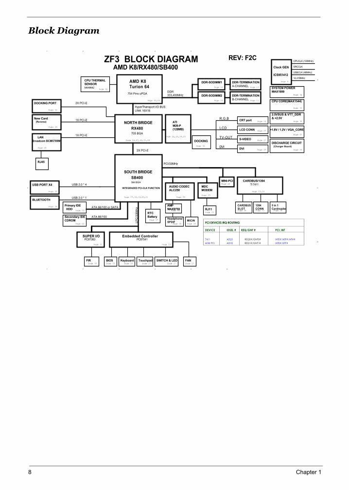
Block Diagram
1
1
2
2
3
3
4
4
5
5 6
A
C C
D
DISCHARGE CIRCUIT
SRCCLK
Page 11
Page 22
REQ0#/GNT0#
Page 02,03
Page 10
754 Pins uPGA
Page 11
USB PORT X4
DDR-SODIMM1
B-CHANNEL
LCD
INTEGRADED PCI-CLK FUNCTION
TI 7411
INTE#,INTF#
AD25
Page 17,18,19,20,21
SOUTH BRIDGE
Page 16
REQ1#/GNT1#
HyperThansport I/O BUS
705 BGA
IDSEL #
Clock GEN
ICS951412
CARDBUSSLOT
CPU CORE(MAX1544)
TV-OUT
A-CHANNEL
LINK 16X16
S-VIDEO
RJ45
MINI PCI
Page 26
Primary IDE HDD
MAX6642
Embedded Controller
Broadcom BCM5789M
USB 2.0 * 4
LP
C/3
3M
Hz
2X PCI-E
Page 29
Page 02
Page 24
PC87383
NORTH BRIDGE
Page 28
Page 04,05,06,07,08
Page 17
5 in 1 Cardreader
CPUCLK (100MHz)
DEVICE
MINI-PCI
AMD K8Turion 64
INTE#,INTF#,INTH#
AUDIO CODECALC250
PCI DEVICES IRQ ROUTING
PCI/33MHz
SB400
RJ11
Page 34
Page 25
7411
14.318MHz
MDCMODEM
DVI
Page 10
BLUETOOTH
Page 33
R,G,B
Page 24
1394CONN
Page 28
LCD CONN
CRT port
Page 27
LAN
Page 23,24
Page 32
PCI_INT
MICIN
REQ/GNT #
DDR-TERMINATION
ATA 66/100 or SATA
PC87541
CARDBUS/1394
AMD K8/RX480/SB400
Page 34
DDR-TERMINATION
ATI M26-P(128MB)
USBCLK (48MHz)
DDR-SODIMM2
CPU THERMALSENSOR
Page 27
RTCBattery
Page 35
Page 27
USB 2.0 * 1
Page 12,13,14,15
Page 25
Page 22
SUPER I/O
Page 29
+1.8V / 1.2V / VGA_CORE
2.5VSUS & VTT_DDR& +2.5V
RX480
Secondary IDECDROM
Page 37
ATA 66/100
Page 31
Page 9
DVI
SYSTEM POWERMAX1999
564 BGA
AD18
ZF3 BLOCK DIAGRAM
Page 23
DOCKING
Page 36
DDR333,400MHz
FANPage 27 Page 27
BIOS TouchpadKeyboard SWITCH & LEDPage 30
FIRPage 33 Page 27Page 33
AMP MAX9755
Page 30
Headphone/SPDIF
Page 30
Page 30
(Charger Board)
2X PCI-E
1X PCI-E
DOCKING PORT
Page 28
New Card
Page 32
(Reverse)
1X PCI-E
REV: F2C
8 Chapter 1
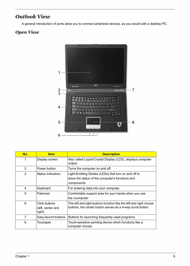
Outlook ViewA general introduction of ports allow you to connect peripheral devices, as you would with a desktop PC.
Open View
No. Item Description1 Display screen Also called Liquid-Crystal Display (LCD), displays computer
output.
2 Power button Turns the computer on and off.
3 Status indicators Light-Emitting Diodes (LEDs) that turn on and off to show the status of the computer's functions and components.
4 Keyboard For entering data into your computer.
5 Palmrest Comfortable support area for your hands when you use the coumputer
6 Click buttons (left, center and right)
The left and right buttons function like the left and right mouse buttons; the center button serves as a 4-way scroll button.
7 Easy-launch buttons Buttons for launching frequently used programs.
8 Touchpad Touch-sensitive pointing device which functions like a computer mouse.
Just for Starters...
# Item Description
Chapter 1 9
"Easy-launch buttons" on page 10
# Item Description
"Easy-launch buttons" on page 10
# Item Description
"Easy-launch buttons" on page 10
# Item Description
# Item Description
# Item Description
# Item Description
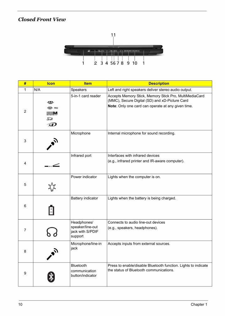
Closed Front View
# Icon Item Description1 N/A Speakers Left and right speakers deliver stereo audio output.
2
5-in-1 card reader Accepts Memory Stick, Memory Stick Pro, MultiMediaCard (MMC), Secure Digital (SD) and xD-Picture CardNote: Only one card can operate at any given time.
3
Microphone Internal microphone for sound recording.
4
Infrared port Interfaces with infrared devices (e.g., infrared printer and IR-aware computer).
5
Power indicator Lights when the computer is on.
6
Battery indicator Lights when the battery is being charged.
7
Headphones/speaker/line-out jack with S/PDIF support
Connects to audio line-out devices (e.g., speakers, headphones).
8
Microphone/line-in jack
Accepts inputs from external sources.
9
Bluetoothcommunication button/indicator
Press to enable/disable Bluetooth function. Lights to indicate the status of Bluetooth communications.
# Icon Item Description
# Icon Item Description
# Icon Item Description
"Launch keys" on page 10
# Icon Item Description
"Launch keys" on page 10
# Icon Item Description
# Item Description
"Launch keys" on page 10
# Icon Item Description
# Icon Item Description
"Easy-launch buttons" on page 10
# Icon Item Description
"Launch keys" on page 10
# Icon Item Description
# Item Description
10 Chapter 1
# Icon Item Description
"Launch keys" on page 10
# Icon Item Description
# Item Description
# Icon Item Description
# Icon Item Description
# Icon Item Description
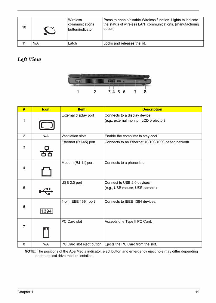
Left View
NOTE: The positions of the AcerMedia indicator, eject button and emergency eject hole may differ depending on the optical drive module installed.
10
Wireless communicationsbutton/indicator
Press to enable/disable Wireless function. Lights to indicate the status of wireless LAN communications. (manufacturing option)
11 N/A Latch Locks and releases the lid.
# Icon Item Description
1External display port Connects to a display device
(e.g., external monitor, LCD projector)
2 N/A Ventilation slots Enable the computer to stay cool
3Ethernet (RJ-45) port Connects to an Ethernet 10/100/1000-based network
4Modem (RJ-11) port Connects to a phone line
5USB 2.0 port Connect to USB 2.0 devices
(e.g., USB mouse, USB camera)
64-pin IEEE 1394 port Connects to IEEE 1394 devices.
7PC Card slot Accepts one Type II PC Card.
8 N/A PC Card slot eject button Ejects the PC Card from the slot.
# Icon Item Description# Icon Item Description
Note:
# Icon Item Description
# Icon Item Description
Note:
# Icon Item Description
# Icon Item Description
# Icon Item Description
# Item Description
# Icon Item Description
# Icon Item Description
Chapter 1 11
Note:
# Icon Item Description
Note:
# Icon Item Description
# Icon Item Description
# Icon Item Description
# Icon Item Description
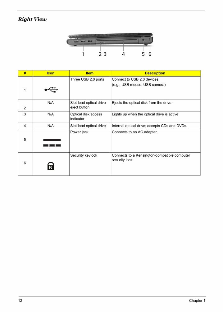
Right View
# Icon Item Description
1
Three USB 2.0 ports Connect to USB 2.0 devices (e.g., USB mouse, USB camera)
2N/A Slot-load optical drive
eject buttonEjects the optical disk from the drive.
3 N/A Optical disk access indicator
Lights up when the optical drive is active
4 N/A Slot-load optical drive Internal optical drive; accepts CDs and DVDs.
5
Power jack Connects to an AC adapter.
6
Security keylock Connects to a Kensington-compatible computer security lock.
Note:
# Icon Item Description
# Item Description
# Icon Item Description
Note:
# Icon Item Description
Note:
# Icon Item Description
12 Chapter 1
# Icon Item Description
Chapter 1 13
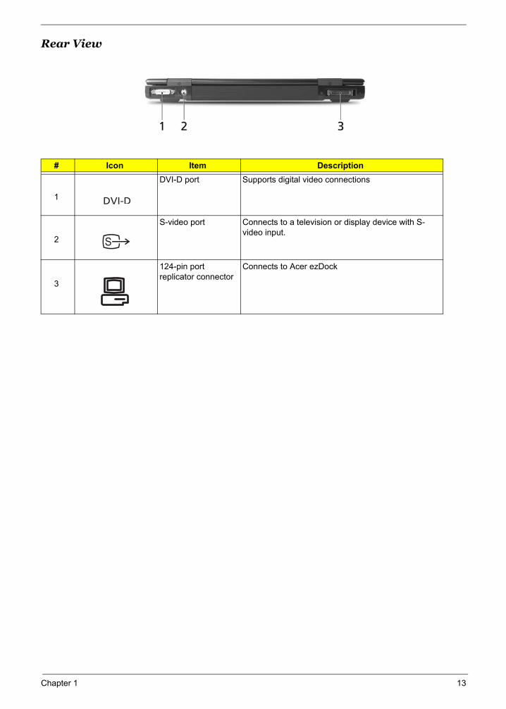
Rear View
# Icon Item Description
1
DVI-D port Supports digital video connections
2
S-video port Connects to a television or display device with S-video input.
3
124-pin port replicator connector
Connects to Acer ezDock
# Icon Item Description
# Item Description
# Icon Item Description
# Item Description
Note:
# Icon Item Description
# Icon Item Description
Note:
# Icon Item Description
# Icon Item Description

14 Chapter 1
Bottom View
# Item Description1 Battery release latches Release the battery for removal
2 Optical drive bay release latch
Releases the optical drive for removal
3 Cooling fan Helps keep the computer coolNote: Do not cover or obstruct the opening of the fan.
4 Optical drive bay Houses the computer's optical drive.
5 Wireless LAN bay Houses the computer's wireless LAN
6 Hard disk bay Houses the computer's hard disk (secured by a screw)
7 Battery bay Houses the computer's battery pack
8 Memory compartment Houses the computer's main memory
# Icon Item Description
# Item Description
Chapter 1 15
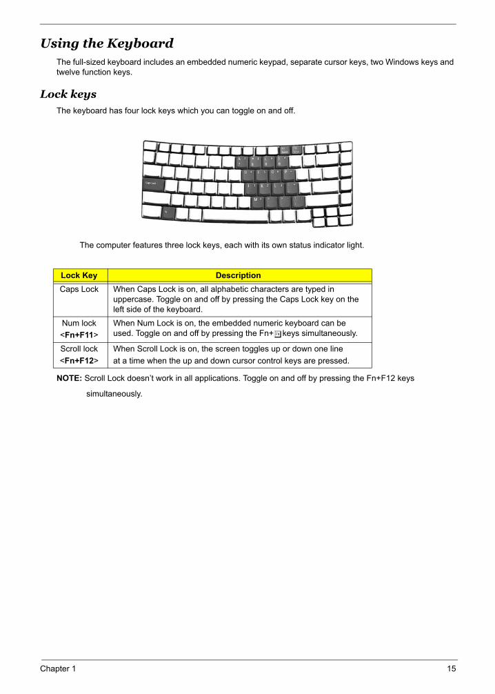
Using the Keyboard The full-sized keyboard includes an embedded numeric keypad, separate cursor keys, two Windows keys and twelve function keys.
Lock keys
The keyboard has four lock keys which you can toggle on and off.
The computer features three lock keys, each with its own status indicator light.
NOTE: Scroll Lock doesn’t work in all applications. Toggle on and off by pressing the Fn+F12 keys
simultaneously.
Lock Key DescriptionCaps Lock When Caps Lock is on, all alphabetic characters are typed in
uppercase. Toggle on and off by pressing the Caps Lock key on the left side of the keyboard.
Num lock<Fn+F11>
When Num Lock is on, the embedded numeric keyboard can be used. Toggle on and off by pressing the Fn+tkeys simultaneously.
Scroll lock<Fn+F12>
When Scroll Lock is on, the screen toggles up or down one lineat a time when the up and down cursor control keys are pressed.
Lock key Description
<Fn> + <F11>
<Fn> + <F12>
Desired access Num Lock on Num Lock off
<Shift> <Fn>
<Fn>
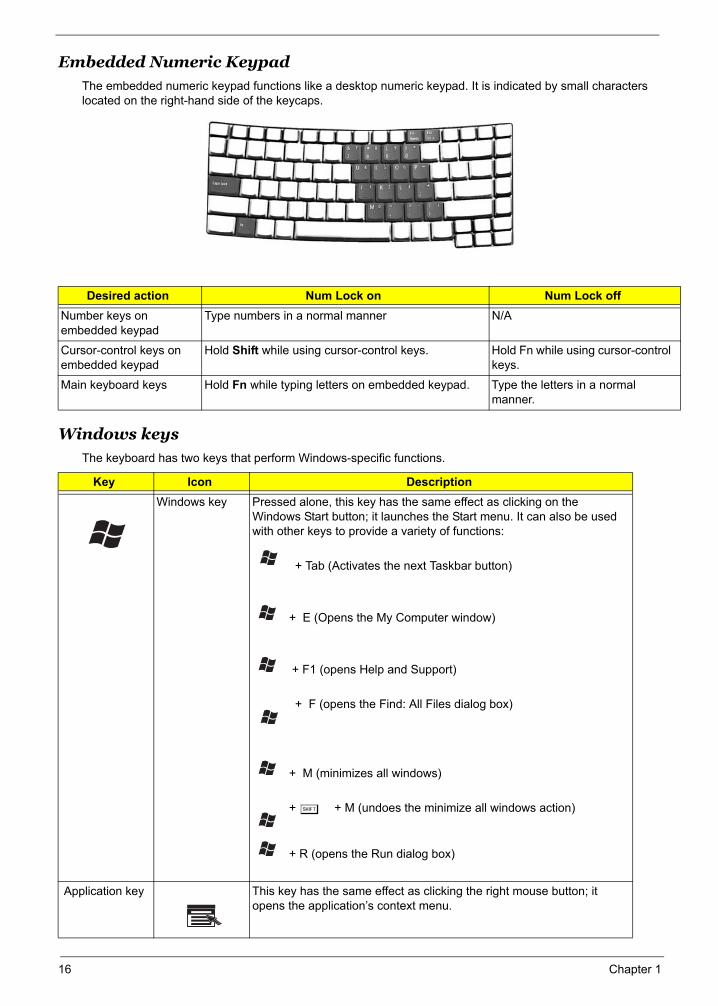
Embedded Numeric KeypadThe embedded numeric keypad functions like a desktop numeric keypad. It is indicated by small characters located on the right-hand side of the keycaps.
Windows keys
The keyboard has two keys that perform Windows-specific functions.
Desired action Num Lock on Num Lock offNumber keys on embedded keypad
Type numbers in a normal manner N/A
Cursor-control keys on embedded keypad
Hold Shift while using cursor-control keys. Hold Fn while using cursor-control keys.
Main keyboard keys Hold Fn while typing letters on embedded keypad. Type the letters in a normal manner.
Key Icon DescriptionWindows key Pressed alone, this key has the same effect as clicking on the
Windows Start button; it launches the Start menu. It can also be used with other keys to provide a variety of functions:
+ Tab (Activates the next Taskbar button)
+ E (Opens the My Computer window)
+ F1 (opens Help and Support)
+ F (opens the Find: All Files dialog box)
+ M (minimizes all windows)
+ j + M (undoes the minimize all windows action)
+ R (opens the Run dialog box)
Application key This key has the same effect as clicking the right mouse button; it opens the application’s context menu.
Lock key Description
<Fn> + <F11>
<Fn> + <F12>
Desired access Num Lock on Num Lock off
<Shift> <Fn>
<Fn>
Key Description
< > + <Tab>:
< > + <E>:
< > + <F1>:
< > + <F>:
+ <R>:
< > + <M>:
<Shift> + < > + <M>:
16 Chapter 1
<Fn>
Key Description
< > + <Tab>:
< > + <E>:
< > + <F1>:
< > + <F>:
+ <R>:
< > + <M>:
<Shift> + < > + <M>:
Hotk
<Fn>
<Fn>
nager" on
<Fn>
<Fn>
<Fn>
<Fn>
<Fn>
<Fn>
<Fn>
<Fn>
<Fn>
<Fn>
H
<
<
<
<
<
<
<
<
<
<
<
<
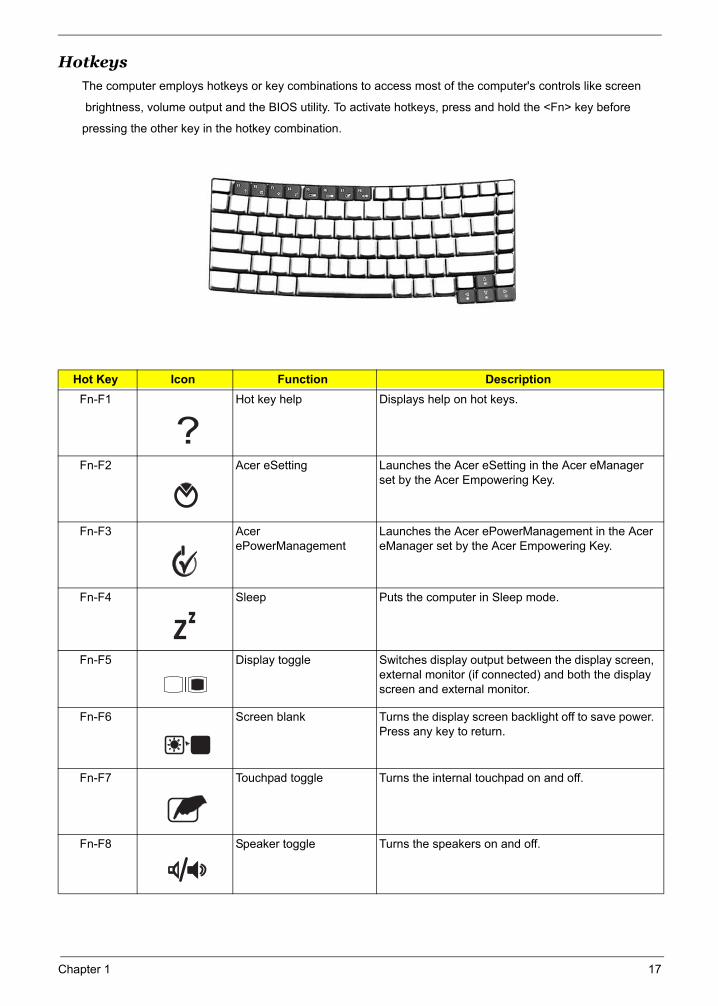
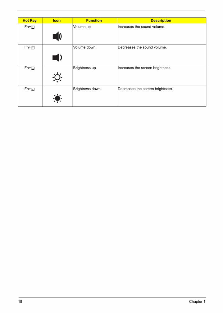
HotkeysThe computer employs hotkeys or key combinations to access most of the computer's controls like screen
brightness, volume output and the BIOS utility. To activate hotkeys, press and hold the <Fn> key before
pressing the other key in the hotkey combination.
Hot Key Icon Function DescriptionFn-F1 Hot key help Displays help on hot keys.
Fn-F2 Acer eSetting Launches the Acer eSetting in the Acer eManager set by the Acer Empowering Key.
Fn-F3 Acer ePowerManagement
Launches the Acer ePowerManagement in the Acer eManager set by the Acer Empowering Key.
Fn-F4 Sleep Puts the computer in Sleep mode.
Fn-F5 Display toggle Switches display output between the display screen, external monitor (if connected) and both the display screen and external monitor.
Fn-F6 Screen blank Turns the display screen backlight off to save power. Press any key to return.
Fn-F7 Touchpad toggle Turns the internal touchpad on and off.
Fn-F8 Speaker toggle Turns the speakers on and off.
<Fn>
ey Icon Function Description
+ <F1>
+ <F2>
"Acer eMa
page 20
+ <F3>
+ <F4>
+ <F5>
+ <F6>
+ <F7>
+ <F8>
Hotkey Icon Function Description
<Fn> + <F1>
<Fn> + <F2>
"Acer eManager" on
page 20
<Fn> + <F3>
<Fn> + <F4>
<Fn> + <F5>
<Fn> + <F6>
<Fn> + <F7>
<Fn> + <F8>
<Fn> + < >
<Fn> + < >
Hotkey Icon Function Description
<Fn> + <F1>
<Fn> + <F2>
"Acer eManager" on
page 20
<Fn> + <F3>
<Fn> + <F4>
<Fn> + <F5>
<Fn> + <F6>
<Fn> + <F7>
<Fn> + <F8>
<Fn> + < >
<Fn> + < >
Hotkey Icon Function Description
<Fn> + <F1>
<Fn> + <F2>
"Acer eManager" on
page 20
<Fn> + <F3>
<Fn> + <F4>
<Fn> + <F5>
<Fn> + <F6>
<Fn> + <F7>
<Fn> + <F8>
<Fn> + < >
Hotkey Icon Function Description
<Fn> + <F1>
<Fn> + <F2>
"Acer eManager" on
page 20
<Fn> + <F3>
<Fn> + <F4>
<Fn> + <F5>
<Fn> + <F6>
<Fn> + <F7>
<Fn> + <F8>
<Fn> + < >
Hotkey Icon Function Description
<Fn> + <F1>
<Fn> + <F2>
"Acer eManager" on
page 20
<Fn> + <F3>
<Fn> + <F4>
<Fn> + <F5>
<Fn> + <F6>
<Fn> + <F7>
<Fn> + <F8>
<Fn> + < >
otkey Icon Function Description
Fn> + <F1>
Fn> + <F2>
"Acer eManager" on
page 20
Fn> + <F3>
Fn> + <F4>
Fn> + <F5>
Fn> + <F6>
Fn> + <F7>
Fn> + <F8>
Fn> + < >
Hotkey Icon Function Description
<Fn> + <F1>
<Fn> + <F2>
"Acer eManager" on
page 20
<Fn> + <F3>
<Fn> + <F4>
<Fn> + <F5>
<Fn> + <F6>
<Fn> + <F7>
<Fn> + <F8>
<Fn> + < >
Chapter 1 17 + < >
+ < >
+ < >
+ < >
<Fn> + < >
<Fn> + < ><Fn> + < >
<Fn> + < >
<Fn> + < >
<Fn> + < >
<Fn> + < >
<Fn> + < >
<Fn> + < >
<Fn> + < >
<Fn> + < >
<Fn> + < >
<Fn> + < >
Fn> + < >
Fn> + < >
Fn> + < >
<Fn> + < >
<Fn> + < >
<Fn> + < >
Hotkey Icon Function Description
<Fn> + <F1>
<Fn> + <F2>
"Acer eManager" on
page 20
<Fn> + <F3>
<Fn> + <F4>
<Fn> + <F5>
<Fn> + <F6>
<Fn> + <F7>
Hotkey Icon Function Description
<Fn> + <F1>
<Fn> + <F2>
"Acer eManager" on
page 20
<Fn> + <F3>
<Fn> + <F4>
<Fn> + <F5>
<Fn> + <F6>
<Fn> + <F7>
<
<
<
<
<
Hotkey Icon Function Description
<Fn> + <F1>
<Fn> + <F2>
"Acer eManager" on
page 20
<Fn> + <F3>
<Fn> + <F4>
<Fn> + <F5>
<Fn> + <F6>
<Fn> + <F7>
Hotkey Icon Function Description
<Fn> + <F1>
<Fn> + <F2>
"Acer eManager" on
page 20
<Fn> + <F3>
<Fn> + <F4>
<Fn> + <F5>
<Fn> + <F6>
<Fn> + <F7>
Fn+w Volume up Increases the sound volume.
Fn+y Volume down Decreases the sound volume.
Fn+x Brightness up Increases the screen brightness.
Fn+z Brightness down Decreases the screen brightness.
Hot Key Icon Function Description<Fn> + <F8>
<Fn> + < >
<Fn> + < >
<Fn> + < >
<Fn> + < >
Fn> + <F8>
Fn> + < >
Fn> + < >
Fn> + < >
Fn> + < >
<Fn> + <F8>
<Fn> + < >
<Fn> + < >
<Fn> + < >
<Fn> + < >
<Fn> + <F8>
<Fn> + < >
<Fn> + < >
<Fn> + < >
<Fn> + < >
18 Chapter 1
Chapter 1 19
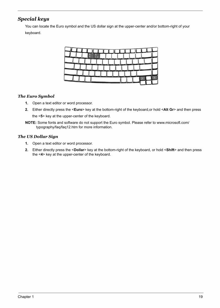
Special keysYou can locate the Euro symbol and the US dollar sign at the upper-center and/or bottom-right of your
keyboard.
The Euro Symbol
1. Open a text editor or word processor.
2. Either directly press the <Euro> key at the bottom-right of the keyboard,or hold <Alt Gr> and then press
the <5> key at the upper-center of the keyboard.
NOTE: Some fonts and software do not support the Euro symbol. Please refer to www.microsoft.com/typography/faq/faq12.htm for more information.
The US Dollar Sign
1. Open a text editor or word processor.
2. Either directly press the <Dollar> key at the bottom-right of the keyboard, or hold <Shift> and then press the <4> key at the upper-center of the keyboard.
Euro>
Alt Gr> <5>
Note
www.microsoft.com/typography/faq/faq12.htm
<Dollar>
<Shift> <4>
Note:
#
#
#
#
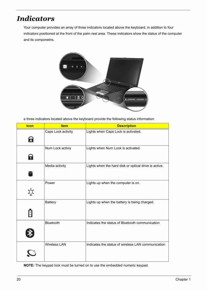
IndicatorsYour computer provides an array of three indicators located above the keyboard, in addition to four
indicators positioned at the front of the palm rest area. These indicators show the status of the computer
and its componetns.
e three indicators located above the keyboard provide the following status information:
NOTE: The keypad lock must be turned on to use the embedded numeric keypad.
Icon Item DescriptionCaps Lock activity Lights when Caps Lock is activated.
Num Lock activiy Lights when Num Lock is activated.
Media activity Lights when the hard disk or optical drive is active.
Power Lights up when the computer is on.
Battery Lights up when the battery is being charged.
Bluetooth Indicates the status of Bluetooth communication
Wireless LAN Indicates the status of wireless LAN communication
1. Charging:
2. Fully charged:
Icon Function Description
"Launch keys" on page 10
# Icon Item Description
# Item Description
"Launch keys" on page 10
# Icon Item Description
# Item Description
"Launch keys" on page 10
Icon Item Description
Item Description
"Launch keys" on page 10
Icon Item Description
Item Description
20 Chapter 1
Chapter 1 21
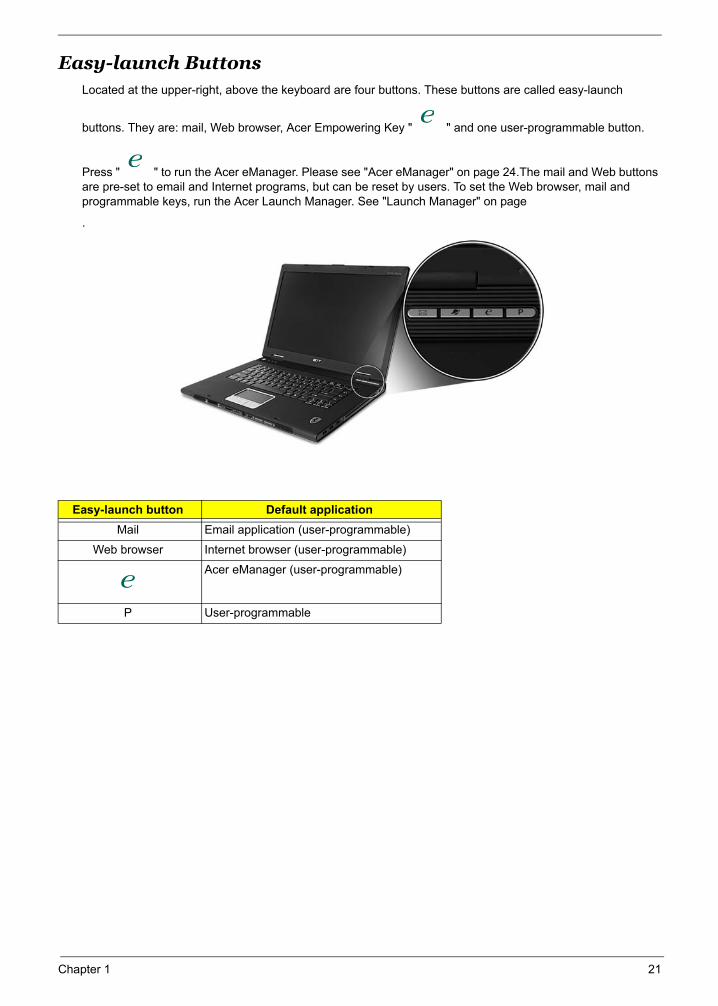
Easy-launch ButtonsLocated at the upper-right, above the keyboard are four buttons. These buttons are called easy-launch
buttons. They are: mail, Web browser, Acer Empowering Key " " and one user-programmable button.
Press " " to run the Acer eManager. Please see "Acer eManager" on page 24.The mail and Web buttons are pre-set to email and Internet programs, but can be reset by users. To set the Web browser, mail and programmable keys, run the Acer Launch Manager. See "Launch Manager" on page
.
Easy-launch button Default applicationMail Email application (user-programmable)
Web browser Internet browser (user-programmable)
Acer eManager (user-programmable)
P User-programmable
"Easy-launch buttons" on page 10
"Easy-launch buttons" on page 10
"Acer eManager" on page 20
"Launch Manager" on page 22
Easy-launch button Default application
"Easy-launch buttons" on page 10
22 Chapter 1
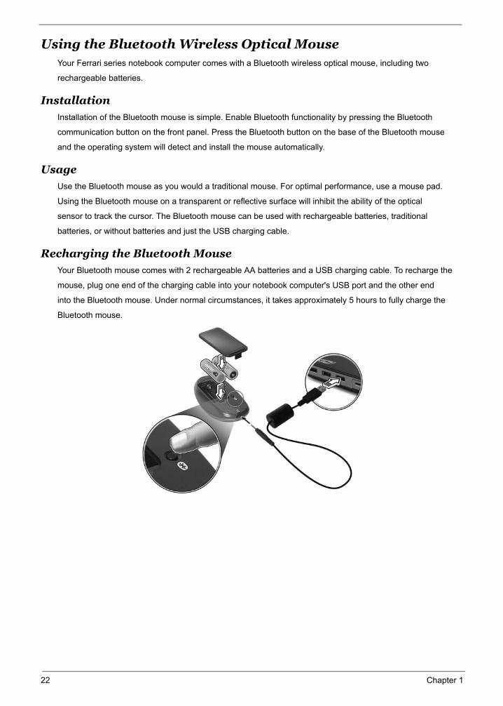
Using the Bluetooth Wireless Optical MouseYour Ferrari series notebook computer comes with a Bluetooth wireless optical mouse, including two
rechargeable batteries.
Installation
Installation of the Bluetooth mouse is simple. Enable Bluetooth functionality by pressing the Bluetooth
communication button on the front panel. Press the Bluetooth button on the base of the Bluetooth mouse
and the operating system will detect and install the mouse automatically.
UsageUse the Bluetooth mouse as you would a traditional mouse. For optimal performance, use a mouse pad.
Using the Bluetooth mouse on a transparent or reflective surface will inhibit the ability of the optical
sensor to track the cursor. The Bluetooth mouse can be used with rechargeable batteries, traditional
batteries, or without batteries and just the USB charging cable.
Recharging the Bluetooth MouseYour Bluetooth mouse comes with 2 rechargeable AA batteries and a USB charging cable. To recharge the
mouse, plug one end of the charging cable into your notebook computer's USB port and the other end
into the Bluetooth mouse. Under normal circumstances, it takes approximately 5 hours to fully charge the
Bluetooth mouse.
"Closed
front view" on page 2 Bluetooth
Important!
Chapter 1 23
Using System Utilities
Acer eManager
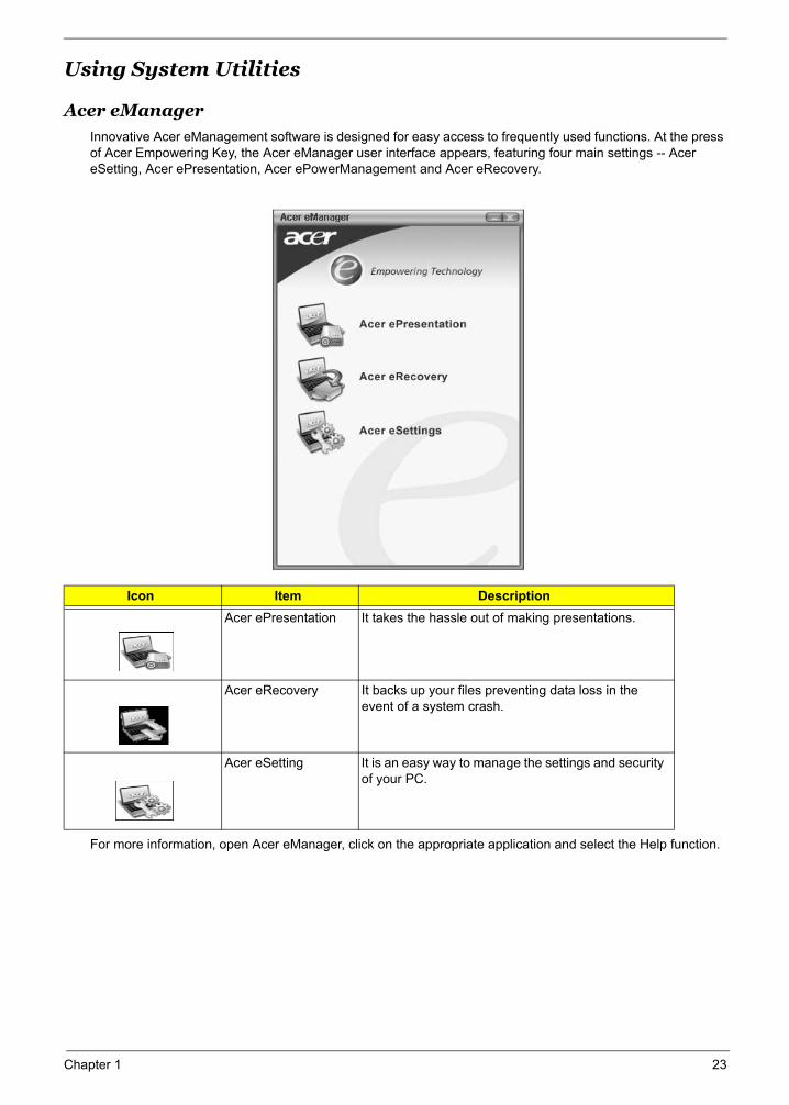
Innovative Acer eManagement software is designed for easy access to frequently used functions. At the press of Acer Empowering Key, the Acer eManager user interface appears, featuring four main settings -- Acer eSetting, Acer ePresentation, Acer ePowerManagement and Acer eRecovery.
For more information, open Acer eManager, click on the appropriate application and select the Help function.
Icon Item DescriptionAcer ePresentation It takes the hassle out of making presentations.
Acer eRecovery It backs up your files preventing data loss in the event of a system crash.
Acer eSetting It is an easy way to manage the settings and security of your PC.
"Easy-launch buttons" on page 10
“Launch keys” on page 20
Acer eSetting
Acer ePresentation
Acer ePowerManagement
Acer eRecovery
“Launch keys” on page 20
Acer eSetting
Acer ePresentation
Acer ePowerManagement
Acer eRecovery
“Launch keys” on page 20
Acer eSetting
Acer ePresentation
Acer ePowerManagement
Acer eRecovery
Note:
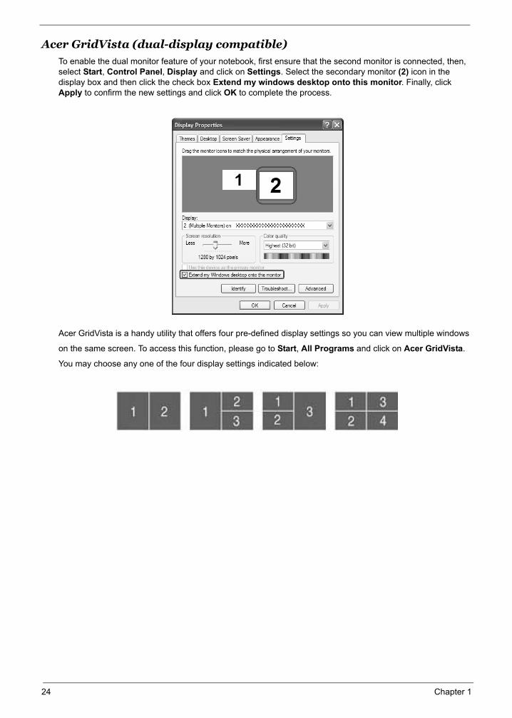
Acer GridVista (dual-display compatible)To enable the dual monitor feature of your notebook, first ensure that the second monitor is connected, then, select Start, Control Panel, Display and click on Settings. Select the secondary monitor (2) icon in the display box and then click the check box Extend my windows desktop onto this monitor. Finally, click Apply to confirm the new settings and click OK to complete the process.
Acer GridVista is a handy utility that offers four pre-defined display settings so you can view multiple windows
on the same screen. To access this function, please go to Start, All Programs and click on Acer GridVista.
You may choose any one of the four display settings indicated below:
Start Control Panel Display
Settings (2)
Extend my windows desktop onto this monitor
Apply OK
Start All Programs Acer GridVista
Note:
Start Control Panel Display
Settings (2)
Extend my windows desktop onto this monitor
Apply OK
Start All Programs Acer GridVista
24 Chapter 1
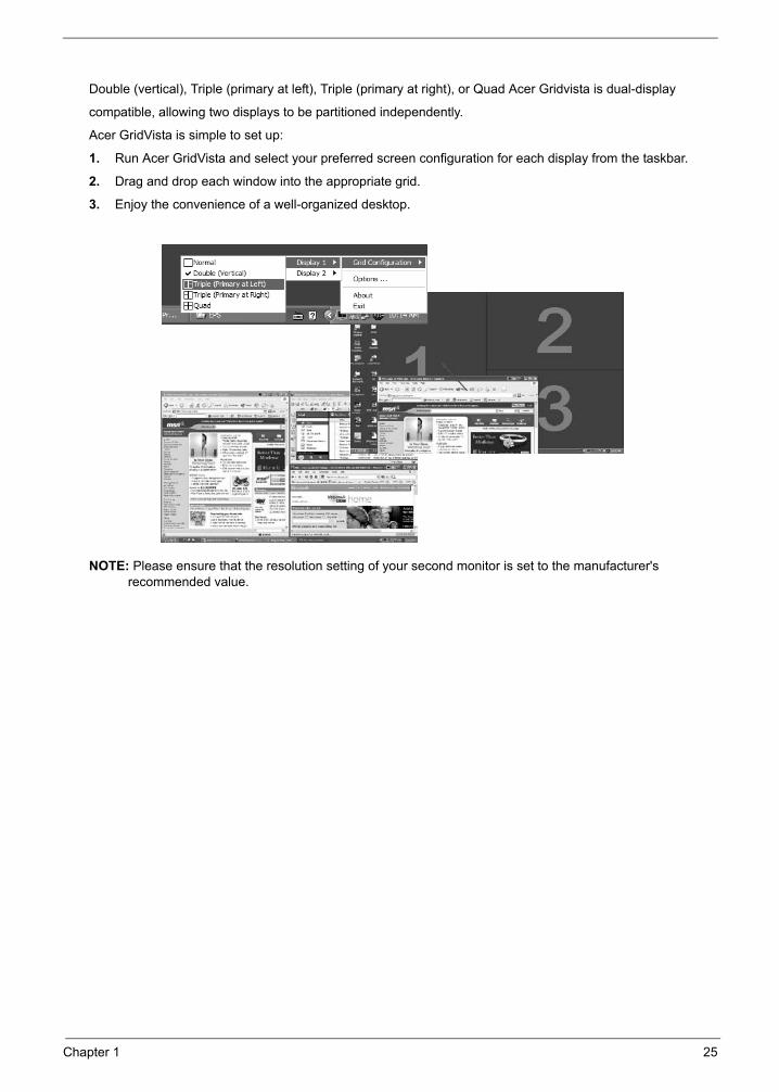
Double (vertical), Triple (primary at left), Triple (primary at right), or Quad Acer Gridvista is dual-display
compatible, allowing two displays to be partitioned independently.
Acer GridVista is simple to set up:
1. Run Acer GridVista and select your preferred screen configuration for each display from the taskbar.
2. Drag and drop each window into the appropriate grid.
3. Enjoy the convenience of a well-organized desktop.
NOTE: Please ensure that the resolution setting of your second monitor is set to the manufacturer's recommended value.Note:
"Easy-launch buttons" on page 10
Start All Programs
Launch Manager
Chapter 1 25
26 Chapter 1
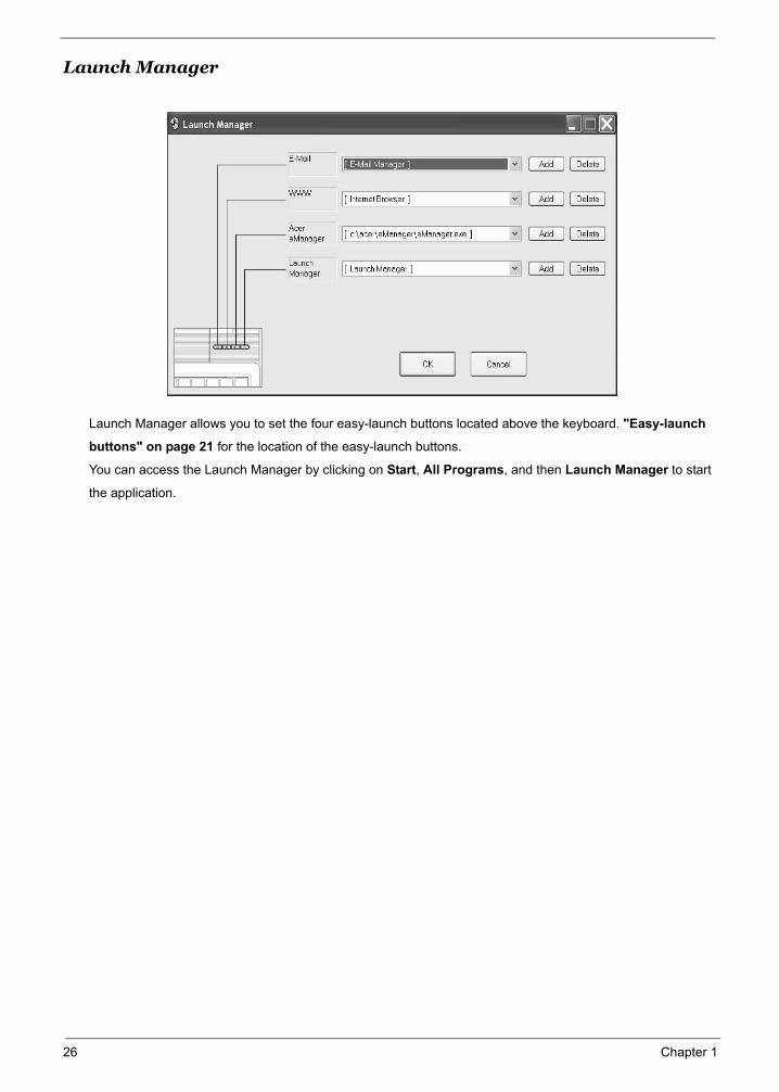
Launch Manager
Launch Manager allows you to set the four easy-launch buttons located above the keyboard. "Easy-launch
buttons" on page 21 for the location of the easy-launch buttons.
You can access the Launch Manager by clicking on Start, All Programs, and then Launch Manager to start
the application.
Note:
"Easy-launch buttons" on page 10
Start All Programs
Launch Manager
Chapter 1 27
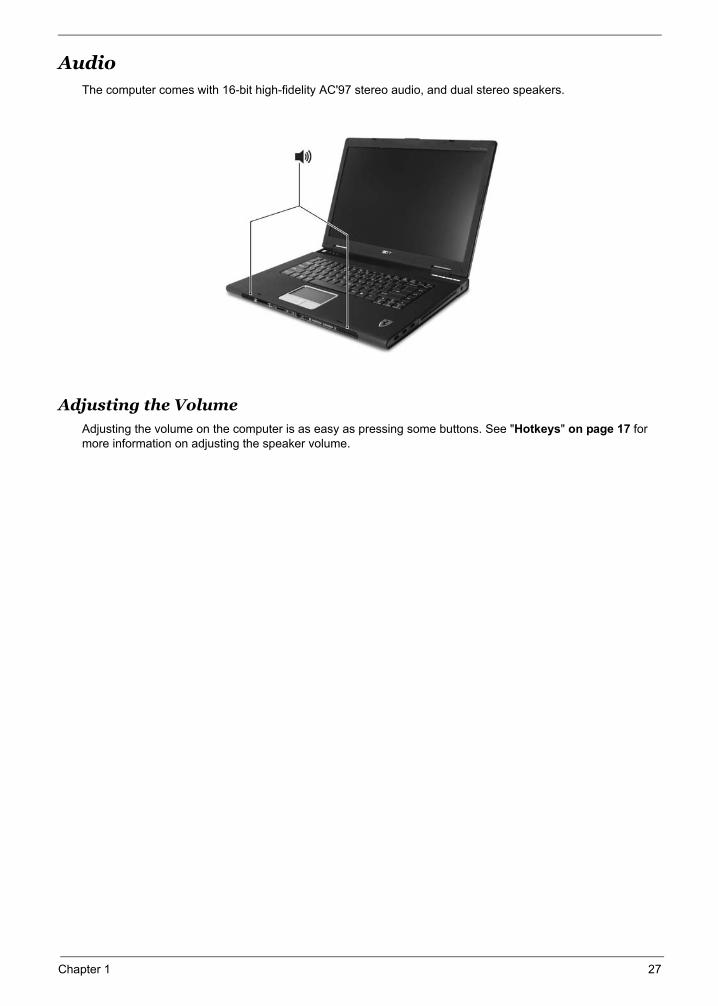
AudioThe computer comes with 16-bit high-fidelity AC'97 stereo audio, and dual stereo speakers.
Adjusting the VolumeAdjusting the volume on the computer is as easy as pressing some buttons. See "Hotkeys" on page 17 for more information on adjusting the speaker volume.
"Hotkeys" on page 14
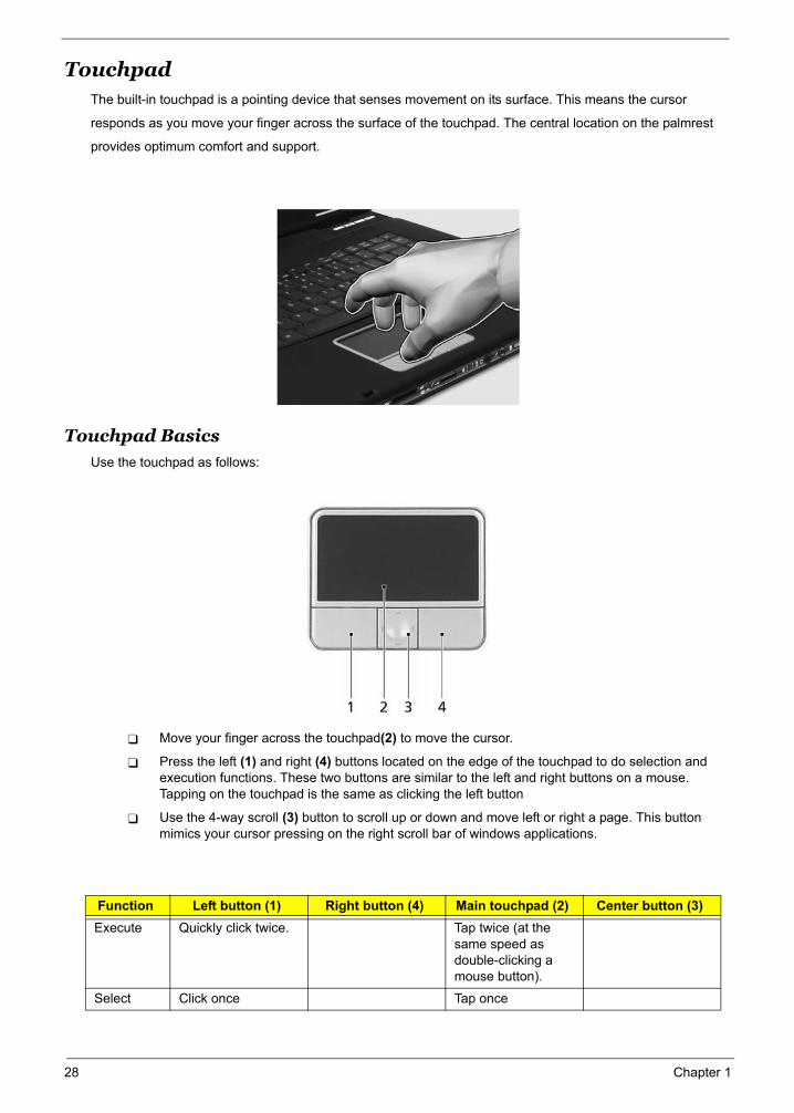
TouchpadThe built-in touchpad is a pointing device that senses movement on its surface. This means the cursor
responds as you move your finger across the surface of the touchpad. The central location on the palmrest
provides optimum comfort and support.
Touchpad Basics
Use the touchpad as follows:
Move your finger across the touchpad(2) to move the cursor.
Press the left (1) and right (4) buttons located on the edge of the touchpad to do selection and execution functions. These two buttons are similar to the left and right buttons on a mouse. Tapping on the touchpad is the same as clicking the left button
Use the 4-way scroll (3) button to scroll up or down and move left or right a page. This button mimics your cursor pressing on the right scroll bar of windows applications.
Function Left button (1) Right button (4) Main touchpad (2) Center button (3)Execute Quickly click twice. Tap twice (at the
same speed as double-clicking a mouse button).
Select Click once Tap once
(2)
(1) (4)
(3)
(2)
(1) (4)
(3)
28 Chapter 1
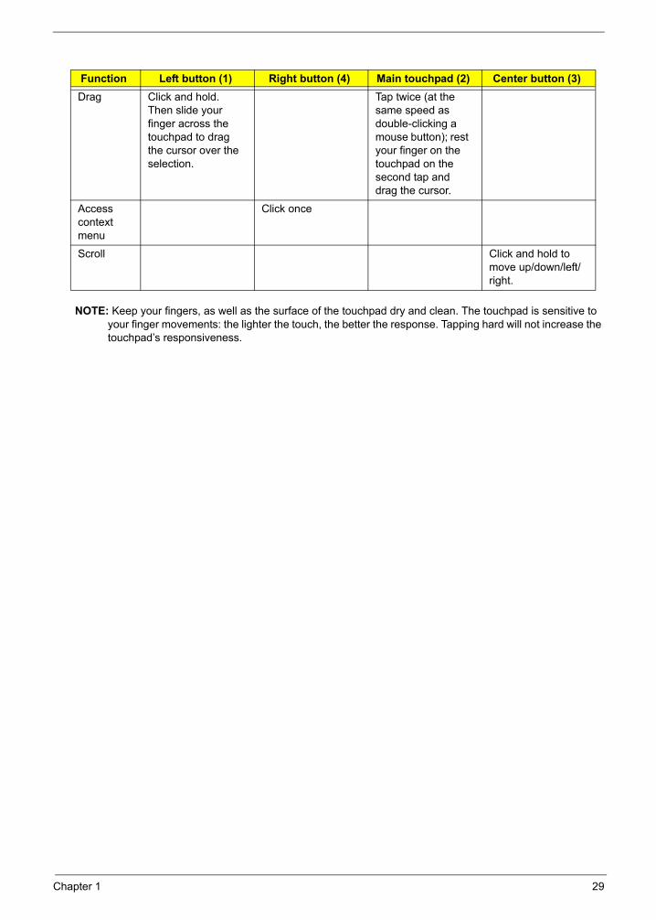
NOTE: Keep your fingers, as well as the surface of the touchpad dry and clean. The touchpad is sensitive to your finger movements: the lighter the touch, the better the response. Tapping hard will not increase the touchpad’s responsiveness.
Drag Click and hold. Then slide your finger across the touchpad to drag the cursor over the selection.
Tap twice (at the same speed as double-clicking a mouse button); rest your finger on the touchpad on the second tap and drag the cursor.
Access context menu
Click once
Scroll Click and hold to move up/down/left/right.
Function Left button (1) Right button (4) Main touchpad (2) Center button (3)
Chapter 1 29
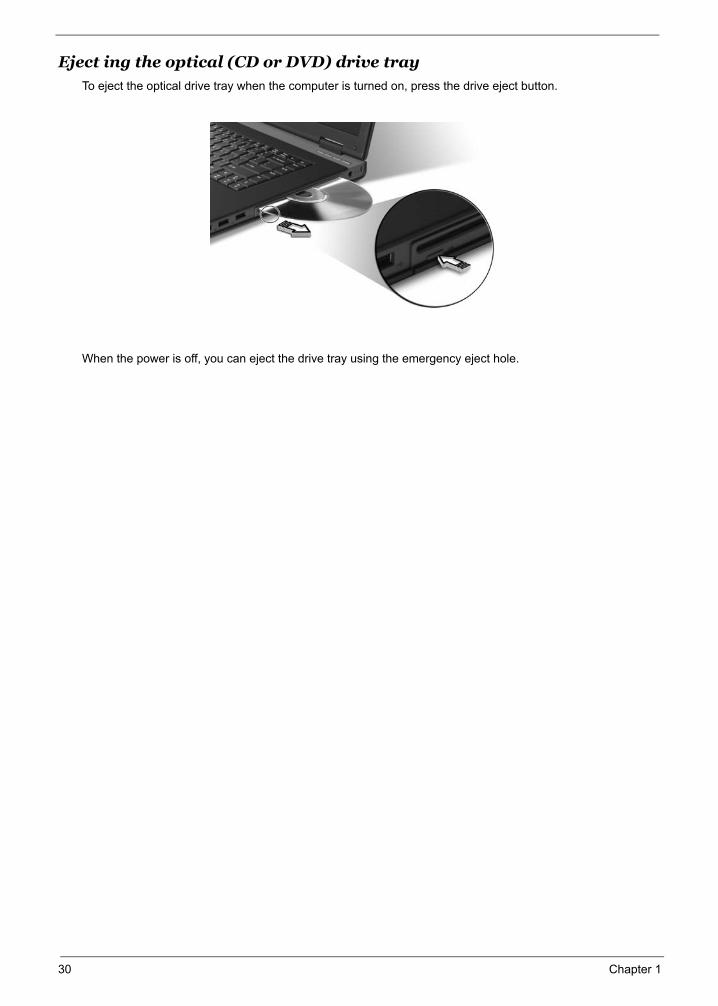
Eject ing the optical (CD or DVD) drive trayTo eject the optical drive tray when the computer is turned on, press the drive eject button.
When the power is off, you can eject the drive tray using the emergency eject hole.
30 Chapter 1
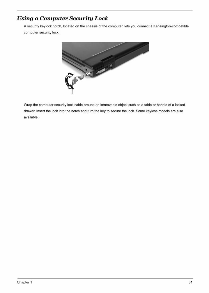
Using a Computer Security LockA security keylock notch, located on the chassis of the computer, lets you connect a Kensington-compatible
computer security lock.
Wrap the computer security lock cable around an immovable object such as a table or handle of a locked
drawer. Insert the lock into the notch and turn the key to secure the lock. Some keyless models are also
available.
Chapter 1 31
Hardware Specifications and Configurations
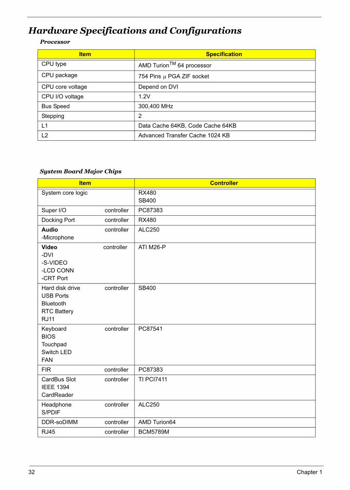
System Board Major Chips
Processor
Item SpecificationCPU type AMD TurionTM 64 processor
CPU package 754 Pins PGA ZIF socket
CPU core voltage Depend on DVI
CPU I/O voltage 1.2V
Bus Speed 300,400 MHz
Stepping 2
L1 Data Cache 64KB, Code Cache 64KB
L2 Advanced Transfer Cache 1024 KB
Item ControllerSystem core logic RX480
SB400
Super I/O controller PC87383
Docking Port controller RX480
Audio controller-Microphone
ALC250
Video controller -DVI -S-VIDEO-LCD CONN-CRT Port
ATI M26-P
Hard disk drive controllerUSB PortsBluetoothRTC BatteryRJ11
SB400
Keyboard controllerBIOSTouchpadSwitch LEDFAN
PC87541
FIR controller PC87383
CardBus Slot controllerIEEE 1394CardReader
TI PCI7411
Headphone controllerS/PDIF
ALC250
DDR-soDIMM controller AMD Turion64
RJ45 controller BCM5789M
µ
32 Chapter 1
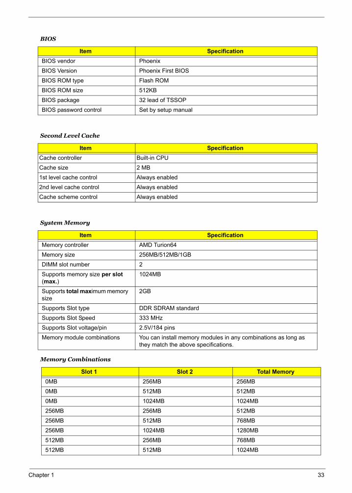
Second Level Cache
System Memory
Memory Combinations
BIOS
Item SpecificationBIOS vendor Phoenix
BIOS Version Phoenix First BIOS
BIOS ROM type Flash ROM
BIOS ROM size 512KB
BIOS package 32 lead of TSSOP
BIOS password control Set by setup manual
Item SpecificationCache controller Built-in CPU
Cache size 2 MB
1st level cache control Always enabled
2nd level cache control Always enabled
Cache scheme control Always enabled
Item SpecificationMemory controller AMD Turion64
Memory size 256MB/512MB/1GB
DIMM slot number 2
Supports memory size per slot (max.)
1024MB
Supports total maximum memory size
2GB
Supports Slot type DDR SDRAM standard
Supports Slot Speed 333 MHz
Supports Slot voltage/pin 2.5V/184 pins
Memory module combinations You can install memory modules in any combinations as long as they match the above specifications.
Slot 1 Slot 2 Total Memory0MB 256MB 256MB
0MB 512MB 512MB
0MB 1024MB 1024MB
256MB 256MB 512MB
256MB 512MB 768MB
256MB 1024MB 1280MB
512MB 256MB 768MB
512MB 512MB 1024MB
Chapter 1 33
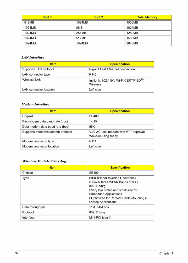
LAN Interface
Modem Interface
Wireless Module 802.11b/g
512MB 1024MB 1536MB
1024MB 0MB 1024MB
1024MB 256MB 1280MB
1024MB 512MB 1536MB
1024MB 1024MB 2048MB
Item SpecificationSupports LAN protocol Gigabit Fast Ethernet connection
LAN connector type RJ45
Wireless LAN InviLink. 802.11b/g Wi-Fi CERTIFIEDTM Wireless
LAN connector location Left side
Item SpecificationChipset SB400
Fax modem data baud rate (bps) 14.1K
Data modem data baud rate (bps) 56K
Supports modem/bluetooth protocol V.92 AC-Link modem with PTT approvalWake-on-Ring ready
Modem connector type RJ11
Modem connector location Left side
Item SpecificationChipset SB400
Type PIFA (Planar Inverted F Antenna)> Cover three WLAN Bands of IEEE 802.11a/b/g>Very low profile and small size for Embedded Applications >Optimized for Remote Cable Mounting in Laptop Applications
Data throughput 11M~54M bps
Protocol 802.11 b+g
Interface Mini-PCI type II
Slot 1 Slot 2 Total Memory
34 Chapter 1
Chapter 1 35
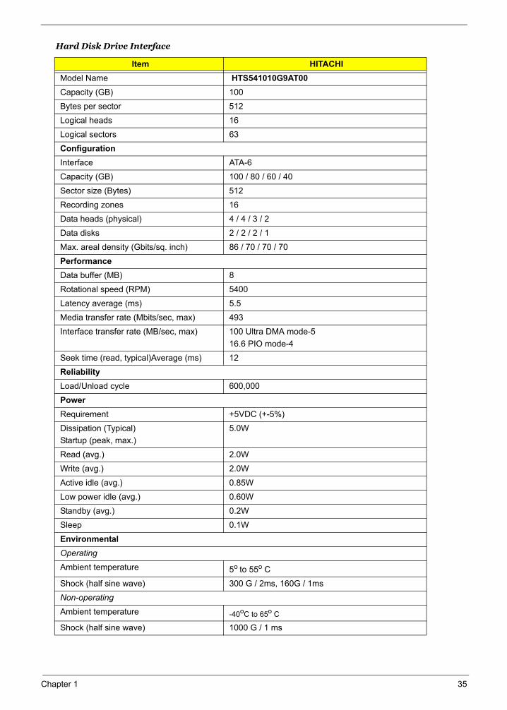
Hard Disk Drive Interface
Item HITACHIModel Name HTS541010G9AT00Capacity (GB) 100
Bytes per sector 512
Logical heads 16
Logical sectors 63
ConfigurationInterface ATA-6
Capacity (GB) 100 / 80 / 60 / 40
Sector size (Bytes) 512
Recording zones 16
Data heads (physical) 4 / 4 / 3 / 2
Data disks 2 / 2 / 2 / 1
Max. areal density (Gbits/sq. inch) 86 / 70 / 70 / 70
PerformanceData buffer (MB) 8
Rotational speed (RPM) 5400
Latency average (ms) 5.5
Media transfer rate (Mbits/sec, max) 493
Interface transfer rate (MB/sec, max) 100 Ultra DMA mode-516.6 PIO mode-4
Seek time (read, typical)Average (ms) 12
ReliabilityLoad/Unload cycle 600,000
PowerRequirement +5VDC (+-5%)
Dissipation (Typical) Startup (peak, max.)
5.0W
Read (avg.) 2.0W
Write (avg.) 2.0W
Active idle (avg.) 0.85W
Low power idle (avg.) 0.60W
Standby (avg.) 0.2W
Sleep 0.1W
Environmental Operating Ambient temperature 5o to 55o C
Shock (half sine wave) 300 G / 2ms, 160G / 1ms
Non-operatingAmbient temperature -40oC to 65o C
Shock (half sine wave) 1000 G / 1 ms
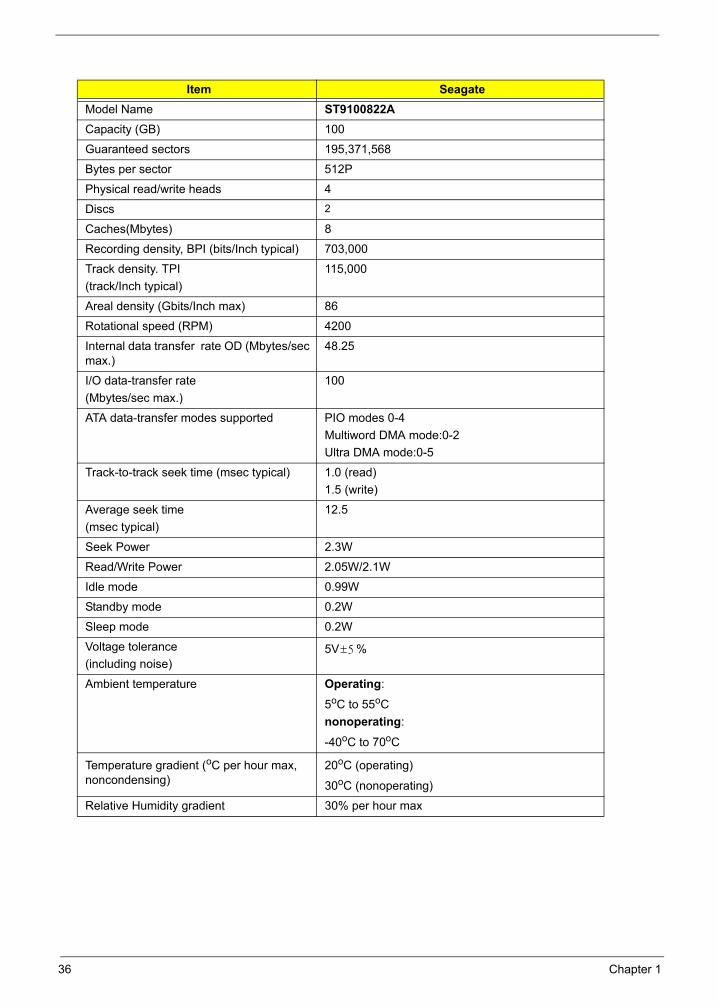
Item SeagateModel Name ST9100822ACapacity (GB) 100
Guaranteed sectors 195,371,568
Bytes per sector 512P
Physical read/write heads 4
Discs 2
Caches(Mbytes) 8
Recording density, BPI (bits/Inch typical) 703,000
Track density. TPI(track/Inch typical)
115,000
Areal density (Gbits/Inch max) 86
Rotational speed (RPM) 4200
Internal data transfer rate OD (Mbytes/sec max.)
48.25
I/O data-transfer rate (Mbytes/sec max.)
100
ATA data-transfer modes supported PIO modes 0-4Multiword DMA mode:0-2Ultra DMA mode:0-5
Track-to-track seek time (msec typical) 1.0 (read)1.5 (write)
Average seek time (msec typical)
12.5
Seek Power 2.3W
Read/Write Power 2.05W/2.1W
Idle mode 0.99W
Standby mode 0.2W
Sleep mode 0.2W
Voltage tolerance(including noise)
5V %
Ambient temperature Operating:
5oC to 55oC nonoperating:
-40oC to 70oC
Temperature gradient (oC per hour max, noncondensing)
20oC (operating)
30oC (nonoperating)
Relative Humidity gradient 30% per hour max
5±
36 Chapter 1
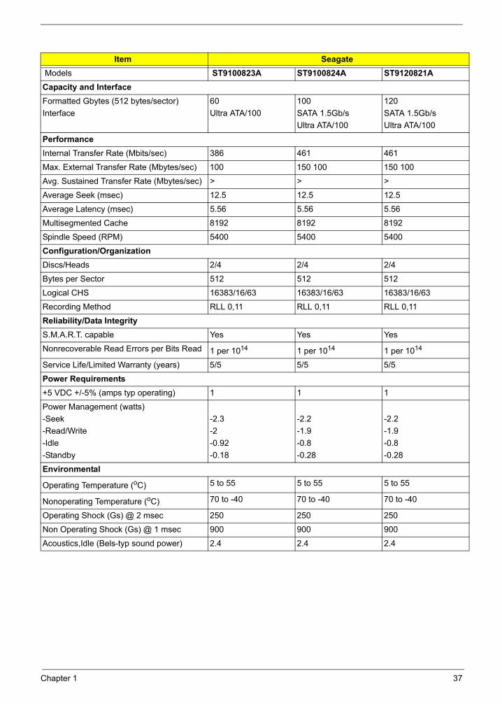
Item Seagate Models ST9100823A ST9100824A ST9120821ACapacity and InterfaceFormatted Gbytes (512 bytes/sector)Interface
60Ultra ATA/100
100SATA 1.5Gb/sUltra ATA/100
120SATA 1.5Gb/sUltra ATA/100
PerformanceInternal Transfer Rate (Mbits/sec) 386 461 461
Max. External Transfer Rate (Mbytes/sec) 100 150 100 150 100
Avg. Sustained Transfer Rate (Mbytes/sec) > > >
Average Seek (msec) 12.5 12.5 12.5
Average Latency (msec) 5.56 5.56 5.56
Multisegmented Cache 8192 8192 8192
Spindle Speed (RPM) 5400 5400 5400
Configuration/OrganizationDiscs/Heads 2/4 2/4 2/4
Bytes per Sector 512 512 512
Logical CHS 16383/16/63 16383/16/63 16383/16/63
Recording Method RLL 0,11 RLL 0,11 RLL 0,11
Reliability/Data IntegrityS.M.A.R.T. capable Yes Yes Yes
Nonrecoverable Read Errors per Bits Read 1 per 1014 1 per 1014 1 per 1014
Service Life/Limited Warranty (years) 5/5 5/5 5/5
Power Requirements+5 VDC +/-5% (amps typ operating) 1 1 1
Power Management (watts)-Seek-Read/Write-Idle-Standby
-2.3 -2 -0.92 -0.18
-2.2-1.9-0.8 -0.28
-2.2-1.9-0.8 -0.28
Environmental
Operating Temperature (oC) 5 to 55 5 to 55 5 to 55
Nonoperating Temperature (oC) 70 to -40 70 to -40 70 to -40
Operating Shock (Gs) @ 2 msec 250 250 250
Non Operating Shock (Gs) @ 1 msec 900 900 900
Acoustics,Idle (Bels-typ sound power) 2.4 2.4 2.4
Chapter 1 37
38 Chapter 1
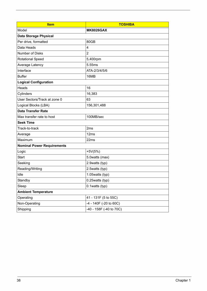
Item TOSHIBAModel MK8026GAXData Storage PhysicalPer drive, formatted 80GB
Data Heads 4
Number of Disks 2
Rotational Speed 5,400rpm
Average Latency 5.55ms
Interface ATA-2/3/4/5/6
Buffer 16MB
Logical ConfigurationHeads 16
Cylinders 16,383
User Sectors/Track at zone 0 63
Logical Blocks (LBA) 156,301,488
Data Transfer RateMax transfer rate to host 100MB/sec
Seek TimeTrack-to-track 2ms
Average 12ms
Maximum 22ms
Nominal Power RequirementsLogic +5V(5%)
Start 5.0watts (max)
Seeking 2.9watts (typ)
Reading/Writing 2.5watts (typ)
Idle 1.05watts (typ)
Standby 0.25watts (typ)
Sleep 0.1watts (typ)
Ambient TemperatureOperating 41 - 131F (5 to 55C)
Non-Operating -4 - 140F (-20 to 60C)
Shipping -40 - 158F (-40 to 70C)
Chapter 1 39
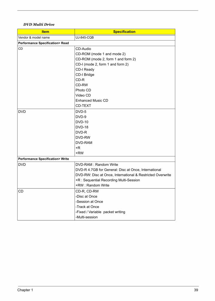
DVD Multi Drive
Item SpecificationVendor & model name UJ-845-CQB
Performance Specification> Read
CD CD-AudioCD-ROM (mode 1 and mode 2)CD-ROM (mode 2, form 1 and form 2)CD-I (mode 2, form 1 and form 2)CD-I ReadyCD-I BridgeCD-RCD-RWPhoto CDVideo CDEnhanced Music CDCD-TEXT
DVD DVD-5DVD-9DVD-10DVD-18DVD-RDVD-RWDVD-RAM+R+RW
Performance Specification> Write
DVD DVD-RAM : Random WriteDVD-R 4.7GB for General: Disc at Once, InternationalDVD-RW: Disc at Once, International & Restricted Overwrite+R : Sequential Recording Multi-Session+RW : Random Write
CD CD-R, CD-RW-Disc at Once -Session at Once-Track at Once-Fixed / Variable packet writing-Multi-session
Audio Port
Video Interface
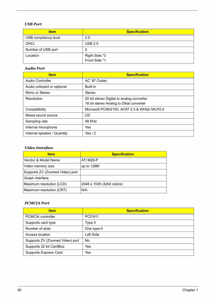
USB Port
Item SpecificationUSB compliancy level 2.0
OHCI USB 2.0
Number of USB port 4
Location Right Side *3Front Side *1
Item SpecificationAudio Controller AC’ 97 Codec
Audio onboard or optional Built-in
Mono or Stereo Stereo
Resolution 20 bit stereo Digital to analog converter18 bit stereo Analog to Ditial converter
Compatibility Microsoft PC99/2100, AC97 2.3 & WHQL/WLP2.0
Mixed sound source CD
Sampling rate 48 KHz
Internal microphone Yes
Internal speaker / Quantity Yes / 2
Item SpecificationVendor & Model Name ATI M26-P
Video memory size up to 128M
Supports ZV (Zoomed Video) port
Graph interface
Maximum resolution (LCD) 2048 x 1536 (32bit colors)
Maximum resolution (CRT) N/A
PCMCIA Port
Item SpecificationPCMCIA controller PCI7411
Supports card type Type II
Number of slots One type-II
Access location Left Side
Supports ZV (Zoomed Video) port No
Supports 32 bit CardBus Yes
Supports Express Card Yes
40 Chapter 1
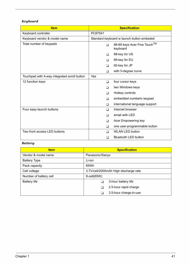
Keyboard
Item SpecificationKeyboard controller PC87541
Keyboard vendor & model name Standard keyboard w launch button embeded
Total number of keypads 88-89 keys Acer Fine TouchTM
keyboard
88-key for US
89-key for EU
92-key for JP
with 5-degree curve
Touchpad with 4-way integrated scroll button Yes
12 function keys four cursor keys
two Windows keys
Hotkey controls
embedded numberic keypad
international language support
Four easy-launch buttons Internet browser
email with LED
Acer Empowering key
one user-programmable button
Two front access LED buttons WLAN LED button
Bluetooth LED button
Battery
Item SpecificationVendor & model name Panasonic/Sanyo
Battery Type Li-ion
Pack capacity 65Wh
Cell voltage 3.7V/cell/2000mAh High discharge rate
Number of battery cell 8-cell(65W)
Battery life 3-hour battery life
2.5-hour rapid charge
3.5-hour charge-in-use
Chapter 1 41
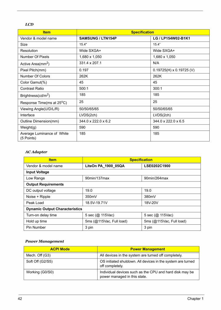
LCD
Item Specification Vendor & model name SAMSUNG / LTN154P LG / LP154W02-B1K1 Size 15.4" 15.4”
Resolution Wide SXGA+ Wide SXGA+
Number Of Pixels 1,680 x 1,050 1,680 x 1,050
Active Area(mm2) 331.4 x 207.1 N/A
Pixel Pitch(mm) 0.197 0.19725(H) x 0.19725 (V)
Number Of Colors 262K 262K
Color Gamut(%) 45 45
Contrast Ratio 500:1 300:1
Brightness(cd/m2) 185 185
Response Time(ms at 25oC) 25 25
Viewing Angle(U/D/L/R) 50/50/65/65 50/50/65/65
Interface LVDS(2ch) LVDS(2ch)
Outline Dimension(mm) 344.0 x 222.0 x 6.2 344.0 x 222.0 x 6.5
Weight(g) 590 590
Average Luminance of White (5 Points)
185 185
AC Adapter
Item SpecificationVendor & model name LiteOn PA_1900_05QA LSE0202C1900Input VoltageLow Range 90min/137max 90min/264max
Output RequirementsDC output voltage 19.0 19.0
Noise + Ripple 350mV 380mV
Peak Load 18.5V-19.71V 18V-20V
Dynamic Output CharacteristicsTurn-on delay time 5 sec (@ 115Vac) 5 sec (@ 115Vac)
Hold up time 5ms (@115Vac, Full load) 5ms (@115Vac, Full load)
Pin Number 3 pin 3 pin
Power Management
ACPI Mode Power ManagementMech. Off (G3) All devices in the system are turned off completely.
Soft Off (G2/S5) OS initiated shutdown. All devices in the system are turned off completely.
Working (G0/S0) Individual devices such as the CPU and hard disk may be power managed in this state.
42 Chapter 1
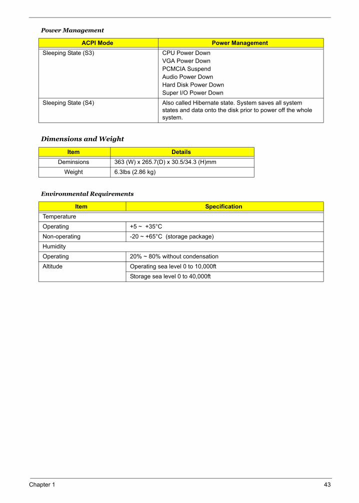
Sleeping State (S3) CPU Power DownVGA Power DownPCMCIA SuspendAudio Power DownHard Disk Power DownSuper I/O Power Down
Sleeping State (S4) Also called Hibernate state. System saves all system states and data onto the disk prior to power off the whole system.
Dimensions and Weight
Item DetailsDeminsions 363 (W) x 265.7(D) x 30.5/34.3 (H)mm
Weight 6.3lbs (2.86 kg)
Environmental Requirements
Item SpecificationTemperature
Operating +5 ~ +35°C
Non-operating -20 ~ +65°C (storage package)
Humidity
Operating 20% ~ 80% without condensation
Altitude Operating sea level 0 to 10,000ft
Storage sea level 0 to 40,000ft
Power Management
ACPI Mode Power Management
Chapter 1 43
System Utilities
Chapter 2
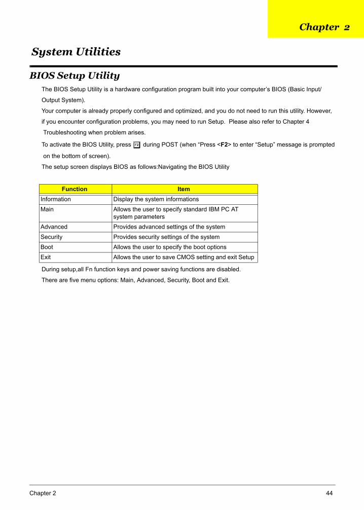
BIOS Setup UtilityThe BIOS Setup Utility is a hardware configuration program built into your computer’s BIOS (Basic Input/
Output System).
Your computer is already properly configured and optimized, and you do not need to run this utility. However,
if you encounter configuration problems, you may need to run Setup. Please also refer to Chapter 4
Troubleshooting when problem arises.
To activate the BIOS Utility, press m during POST (when “Press <F2> to enter “Setup” message is prompted
on the bottom of screen).
The setup screen displays BIOS as follows:Navigating the BIOS Utility
During setup,all Fn function keys and power saving functions are disabled.
There are five menu options: Main, Advanced, Security, Boot and Exit.
Function ItemInformation Display the system informations
Main Allows the user to specify standard IBM PC AT system parameters
Advanced Provides advanced settings of the system
Security Provides security settings of the system
Boot Allows the user to specify the boot options
Exit Allows the user to save CMOS setting and exit Setup
Chapter 2 44
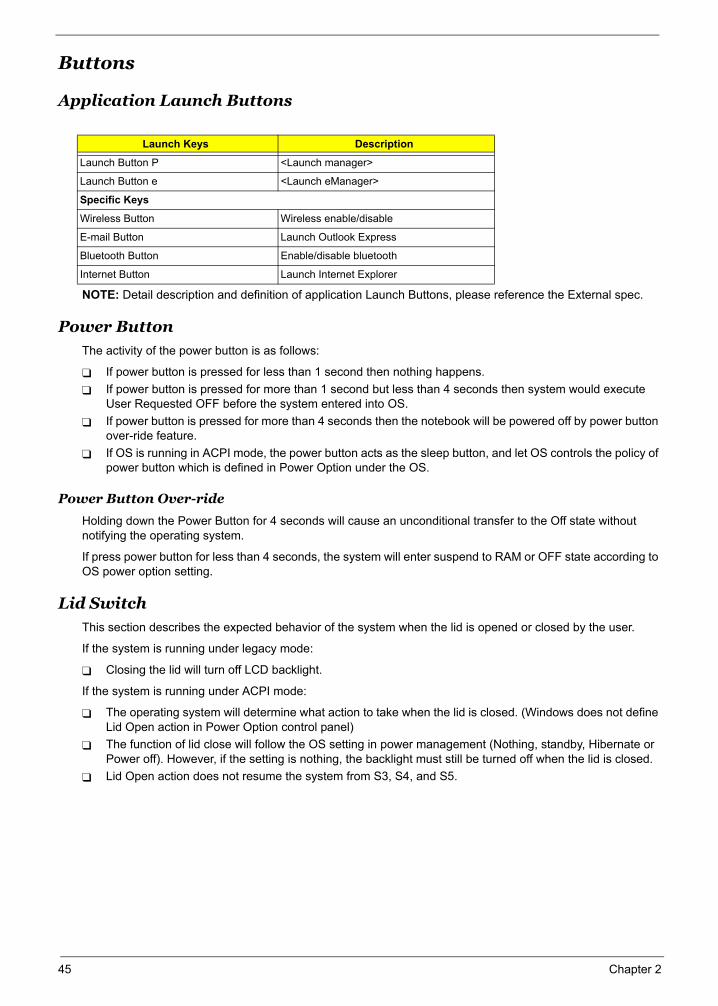
Buttons
Application Launch Buttons
NOTE: Detail description and definition of application Launch Buttons, please reference the External spec.
Power Button
The activity of the power button is as follows:
If power button is pressed for less than 1 second then nothing happens. If power button is pressed for more than 1 second but less than 4 seconds then system would execute User Requested OFF before the system entered into OS.If power button is pressed for more than 4 seconds then the notebook will be powered off by power button over-ride feature. If OS is running in ACPI mode, the power button acts as the sleep button, and let OS controls the policy of power button which is defined in Power Option under the OS.
Power Button Over-ride
Holding down the Power Button for 4 seconds will cause an unconditional transfer to the Off state without notifying the operating system.
If press power button for less than 4 seconds, the system will enter suspend to RAM or OFF state according to OS power option setting.
Lid Switch
This section describes the expected behavior of the system when the lid is opened or closed by the user.
If the system is running under legacy mode:
Closing the lid will turn off LCD backlight.
If the system is running under ACPI mode:
The operating system will determine what action to take when the lid is closed. (Windows does not define Lid Open action in Power Option control panel) The function of lid close will follow the OS setting in power management (Nothing, standby, Hibernate or Power off). However, if the setting is nothing, the backlight must still be turned off when the lid is closed. Lid Open action does not resume the system from S3, S4, and S5.
Launch Keys Description
Launch Button P <Launch manager>
Launch Button e <Launch eManager>
Specific Keys
Wireless Button Wireless enable/disable
E-mail Button Launch Outlook Express
Bluetooth Button Enable/disable bluetooth
Internet Button Launch Internet Explorer
45 Chapter 2
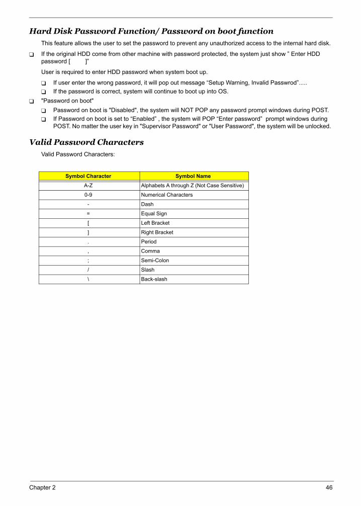
Hard Disk Password Function/ Password on boot function This feature allows the user to set the password to prevent any unauthorized access to the internal hard disk.
If the original HDD come from other machine with password protected, the system just show ” Enter HDD password [ ]”
User is required to enter HDD password when system boot up.
If user enter the wrong password, it will pop out message “Setup Warning, Invalid Passwrod”.....If the password is correct, system will continue to boot up into OS.
"Password on boot" Password on boot is "Disabled", the system will NOT POP any password prompt windows during POST. If Password on boot is set to “Enabled” , the system will POP “Enter password” prompt windows during POST. No matter the user key in "Supervisor Password" or "User Password", the system will be unlocked.
Valid Password Characters
Valid Password Characters:
Symbol Character Symbol Name
A-Z Alphabets A through Z (Not Case Sensitive)
0-9 Numerical Characters
- Dash
= Equal Sign
[ Left Bracket
] Right Bracket
. Period
, Comma
; Semi-Colon
/ Slash
\ Back-slash
Chapter 2 46
47 Chapter 2
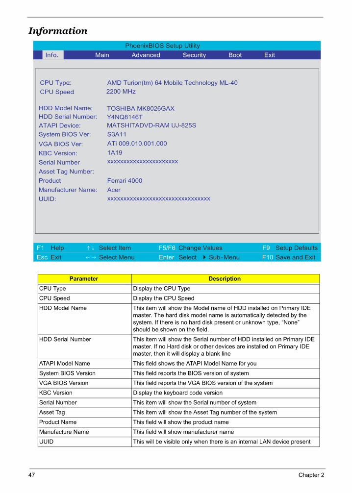
Information
Parameter DescriptionCPU Type Display the CPU Type
CPU Speed Display the CPU Speed
HDD Model Name This item will show the Model name of HDD installed on Primary IDE master. The hard disk model name is automatically detected by the system. If there is no hard disk present or unknown type, “None” should be shown on the field.
HDD Serial Number This item will show the Serial number of HDD installed on Primary IDE master. If no Hard disk or other devices are installed on Primary IDE master, then it will display a blank line
ATAPI Model Name This field shows the ATAPI Model Name for you
System BIOS Version This field reports the BIOS version of system
VGA BIOS Version This field reports the VGA BIOS version of the system
KBC Version Display the keyboard code version
Serial Number This item will show the Serial number of system
Asset Tag This item will show the Asset Tag number of the system
Product Name This field will show the product name
Manufacture Name This field will show manufacturer name
UUID This will be visible only when there is an internal LAN device present
PhoenixBIOS Setup Utility
. Info. Main Advanced Security Boot Exit
CPU Type:: AMD Turion(tm) 64 Mobile Technology ML-40
CPU Speed:
System BIOS Ver:
S3A11
VGA BIOS Ver:
ATi 009.010.001.000
KBC Version:
1A19
Serial Number xxxxxxxxxxxxxxxxxxxxxx
Asset Tag Number:
Product
Ferrari 4000
Manufacturer Name:
Acer
UUID:
xxxxxxxxxxxxxxxxxxxxxxxxxxxxxxxx
F1 Help ↑ ↓ Select Item F5/F6 Change Values F9 Setup Defaults
Esc Exit ← → Select Menu Enter Select 4Sub-Menu F10 Save and Exit
HDD Model Name: HDD Serial Number:
TOSHIBA MK8026GAX Y4NQ8146T
2200 MHz
ATAPI Device: MATSHITADVD-RAM UJ-825S
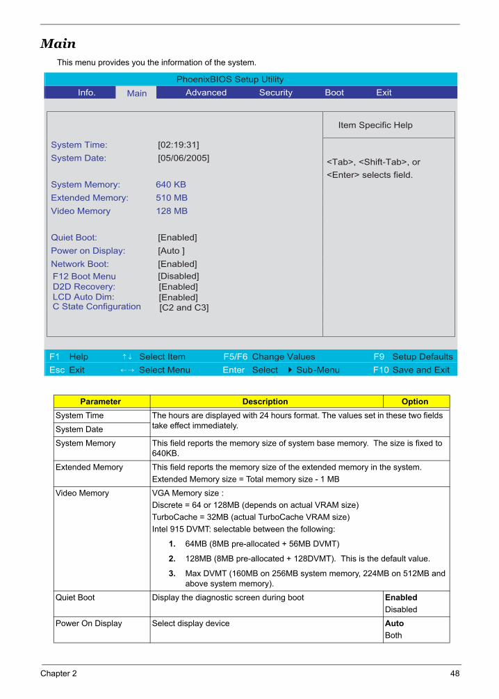
MainThis menu provides you the information of the system.
Parameter Description OptionSystem Time The hours are displayed with 24 hours format. The values set in these two fields
take effect immediately.System Date
System Memory This field reports the memory size of system base memory. The size is fixed to 640KB.
Extended Memory This field reports the memory size of the extended memory in the system. Extended Memory size = Total memory size - 1 MB
Video Memory VGA Memory size :Discrete = 64 or 128MB (depends on actual VRAM size) TurboCache = 32MB (actual TurboCache VRAM size) Intel 915 DVMT: selectable between the following:
1. 64MB (8MB pre-allocated + 56MB DVMT)
2. 128MB (8MB pre-allocated + 128DVMT). This is the default value.
3. Max DVMT (160MB on 256MB system memory, 224MB on 512MB and above system memory).
Quiet Boot Display the diagnostic screen during boot EnabledDisabled
Power On Display Select display device AutoBoth
PhoenixBIOS Setup Utility
Info. Main Advanced Security Boot Exit
Item Specific Help
System Time: [02:19:31]
System Date: [05/06/2005]
System Memory: 640 KB
Extended Memory: 510 MB
Video Memory 128 MB
Quiet Boot: [Enabled]
Power on Display: [Auto ]
Network Boot: [Enabled]
F12 Boot MenuD2D Recovery:LCD Auto Dim:
[Disabled]
<Tab>, <Shift-Tab>, or
<Enter> selects field.
F1 Help ↑ ↓ Select Item F5/F6 Change Values F9 Setup Defaults
Esc Exit ← → Select Menu Enter Select 4Sub-Menu F10 Save and Exit
[Enabled][Enabled]
C State Configuration [C2 and C3]
Chapter 2 48
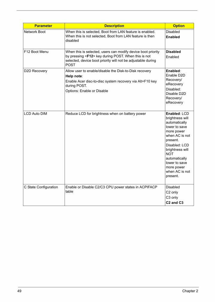
Network Boot When this is selected, Boot from LAN feature is enabled. When this is not selected, Boot from LAN feature is then disabled
Disabled Enabled
F12 Boot Menu When this is selected, users can modify device boot priority by pressing <F12> key during POST. When this is not selected, device boot priority will not be adjustable during POST
DisabledEnabled
D2D Recovery Allow user to enable/disable the Disk-to-Disk recoveryHelp note:Enable Acer disc-to-disc system recovery via Alt+F10 key during POST. Options: Enable or Disable
Enabled: Enable D2D Recovery/eRecovery Disabled: Disable D2D Recovery/eRecovery
LCD Auto DIM Reduce LCD for brightness when on battery power Enabled: LCD brightness will automatically lower to save more power when AC is not present.Disabled: LCD brightness will NOT automatically lower to save more power when AC is not present.
C State Configuration Enable or Disable C2/C3 CPU power states in ACPIFACP table
DisabledC2 onlyC3 onlyC2 and C3
Parameter Description Option
49 Chapter 2
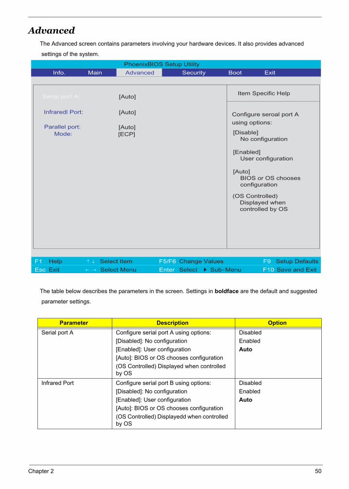
AdvancedThe Advanced screen contains parameters involving your hardware devices. It also provides advanced
settings of the system.
The table below describes the parameters in the screen. Settings in boldface are the default and suggested
parameter settings.
Parameter Description OptionSerial port A Configure serial port A using options:
[Disabled]: No configuration[Enabled]: User configuration[Auto]: BIOS or OS chooses configuration(OS Controlled) Displayed when controlled by OS
DisabledEnabledAuto
Infrared Port Configure serial port B using options:[Disabled]: No configuration[Enabled]: User configuration[Auto]: BIOS or OS chooses configuration(OS Controlled) Displayedd when controlled by OS
DisabledEnabledAuto
PhoenixBIOS Setup Utility
Info. Main Advanced Security Boot Exit
Item Specific Help
Serial port A:
Configure seroal port A
using options:
[Disable] No configuration
[Enabled] User configuration
[Auto] BIOS or OS chooses configuration
(OS Controlled) Displayed when controlled by OS
F1 Help ↑ ↓ Select Item F5/F6 Change Values F9 Setup Defaults
Esc Exit ← → Select Menu Enter Select 4 Sub-Menu F10 Save and Exit
[Auto]
Infraredl Port: [Auto]
Parallel port: [Auto]Mode: [ECP]
Chapter 2 50
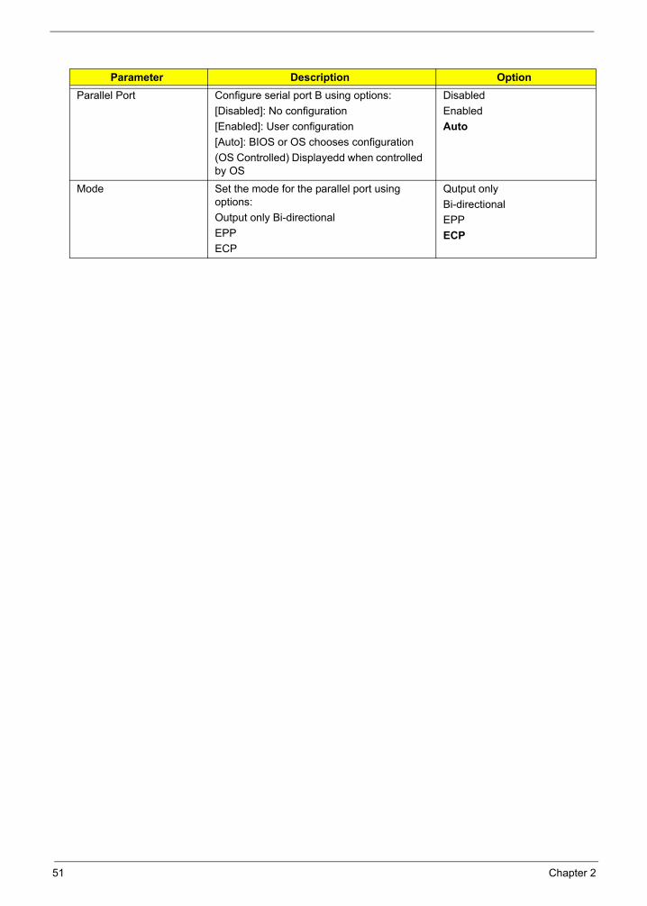
Parallel Port Configure serial port B using options:[Disabled]: No configuration[Enabled]: User configuration[Auto]: BIOS or OS chooses configuration(OS Controlled) Displayedd when controlled by OS
DisabledEnabledAuto
Mode Set the mode for the parallel port using options:Output only Bi-directional EPPECP
Qutput onlyBi-directionalEPPECP
Parameter Description Option
51 Chapter 2
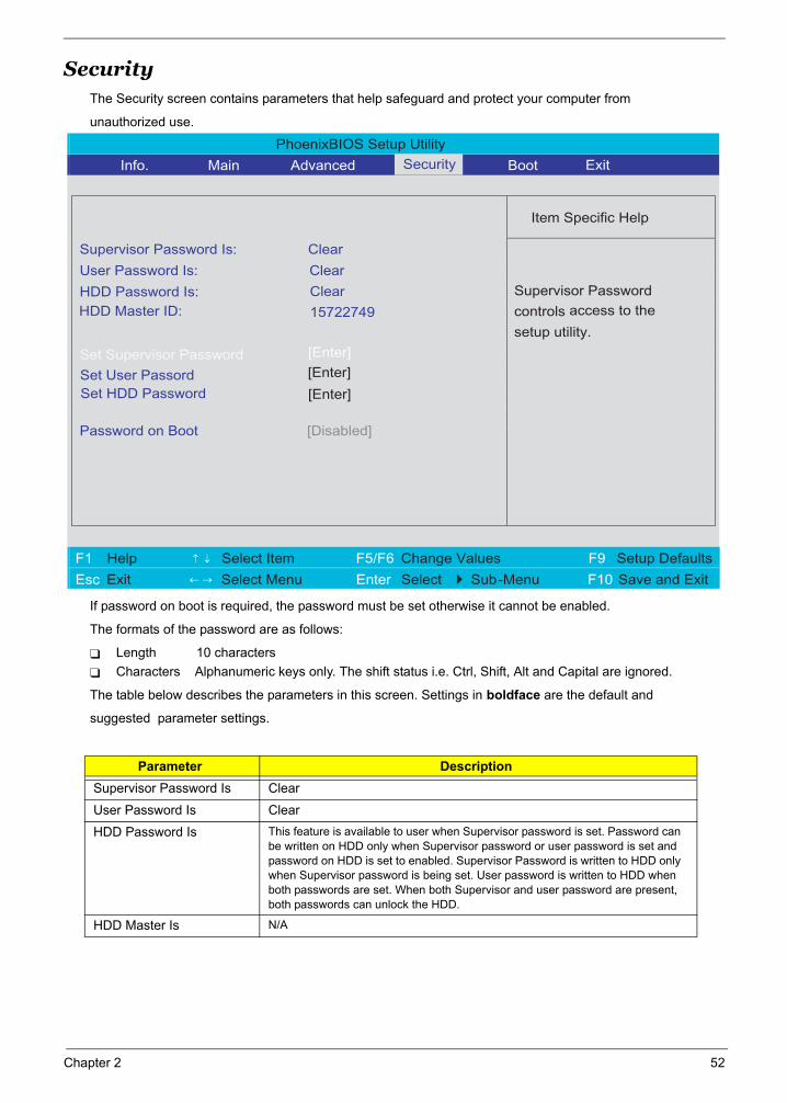
SecurityThe Security screen contains parameters that help safeguard and protect your computer from
unauthorized use.
If password on boot is required, the password must be set otherwise it cannot be enabled.
The formats of the password are as follows:
Length 10 charactersCharacters Alphanumeric keys only. The shift status i.e. Ctrl, Shift, Alt and Capital are ignored.
The table below describes the parameters in this screen. Settings in boldface are the default and
suggested parameter settings.
Parameter DescriptionSupervisor Password Is Clear
User Password Is Clear
HDD Password Is This feature is available to user when Supervisor password is set. Password can be written on HDD only when Supervisor password or user password is set and password on HDD is set to enabled. Supervisor Password is written to HDD only when Supervisor password is being set. User password is written to HDD when both passwords are set. When both Supervisor and user password are present, both passwords can unlock the HDD.
HDD Master Is N/A
PhoenixBIOS Setup Utility
Info. Main Advanced Boot
Item Specific Help
Supervisor Password Is: Clear
User Password Is: Clear
HDD Password Is:
[Enter]Set Supervisor Password
Password on Boot
[Disabled]
Supervisor Password
controls access to the
setup utility.
F1 Help ↑ ↓ Select Item F5/F6 Change Values F9 Setup Defaults
Esc Exit ← → Select Menu Enter Select 4 Sub-Menu F10 Save and Exit
Set User Passord [Enter]
ClearHDD Master ID: 15722749
Set HDD Password [Enter]
ExitSecurity
Chapter 2 52

Set Supervisor Password Defines whether a password is required or not while the events defined in this group happened. The following sub-options are all requires the Supervisor password for changes and should be grayed out if the user password was used to enter setup. When you set Supervisor password already and then you reboot and into BIOS setup manual by User password, the set Supervisor password, Boot device and Lock Hard Drive will be disable. Allows the user to specify whether or not a password is required to boot.
Set User Password
Set HDD Password When shown as [Locked], the hard drive passowrd currently can not be changed or disabled. To change or disable it, turn off the system and enter Setup immediately after turning it back on.Press [Enter] to input, change or disable hard drive password.
Password on boot Defines whether a password is required or not while the events defined in this group happened. The following sub-options are all requires the Supervisor password for changes and should be grayed out if the user password was used to enter setup.
Disabled
Parameter Description
53 Chapter 2
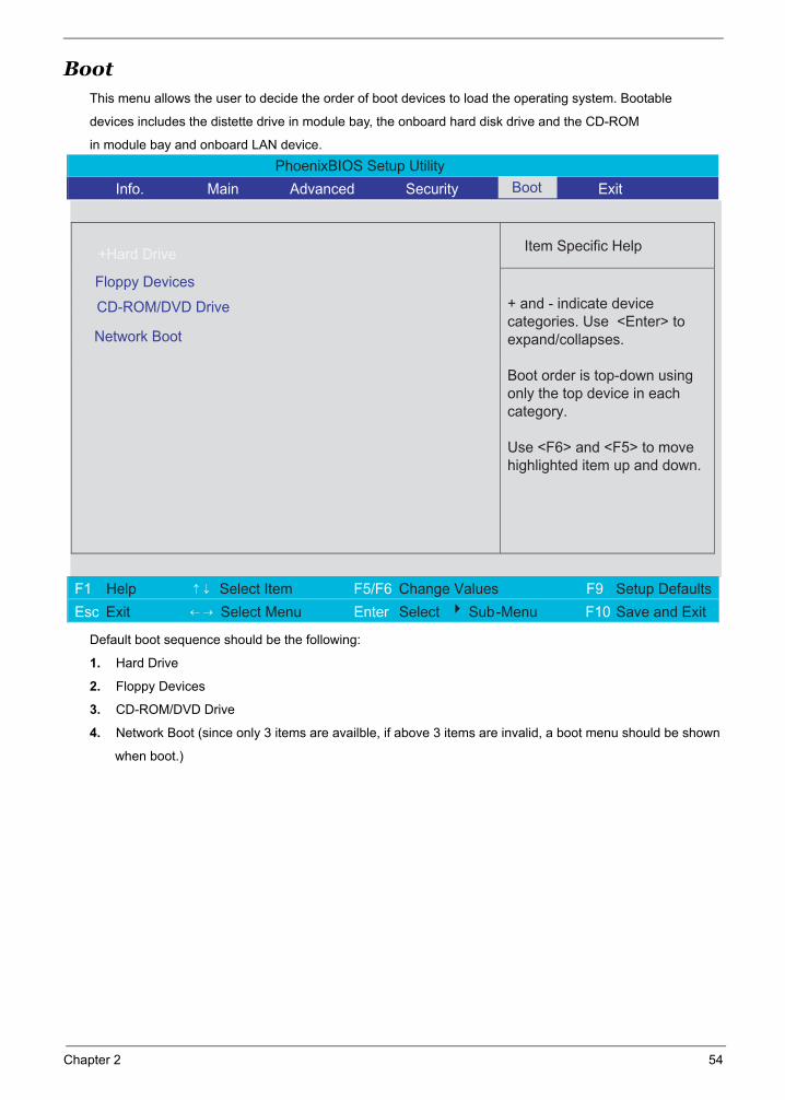
BootThis menu allows the user to decide the order of boot devices to load the operating system. Bootable
devices includes the distette drive in module bay, the onboard hard disk drive and the CD-ROM
in module bay and onboard LAN device.
Default boot sequence should be the following:
1. Hard Drive
2. Floppy Devices
3. CD-ROM/DVD Drive
4. Network Boot (since only 3 items are availble, if above 3 items are invalid, a boot menu should be shown
when boot.)
PhoenixBIOS Setup Utility
Info. Main Advanced Security Exit
Item Specific Help
Floppy Devices
CD-ROM/DVD Drive
+ and - indicate device categories. Use <Enter> to expand/collapses.
Boot order is top-down using only the top device in eachcategory.
Use <F6> and <F5> to movehighlighted item up and down.
F1 Help ↑ ↓ Select Item F5/F6 Change Values F9 Setup Defaults
Esc Exit ← → Select Menu Enter Select 4 Sub-Menu F10 Save and Exit
Network Boot
Boot
+Hard Drive
Chapter 2 54
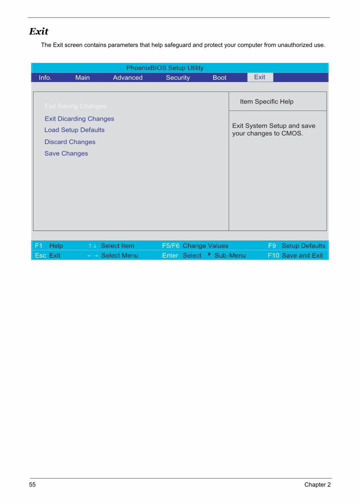
ExitThe Exit screen contains parameters that help safeguard and protect your computer from unauthorized use.
PhoenixBIOS Setup Utility
Info. Main Advanced Security Boot
Item Specific Help
Exit Saving Changes
Exit Dicarding Changes
Load Setup Defaults
Exit System Setup and save your changes to CMOS.
F1 Help ↑ ↓ Select Item F5/F6 Change Values F9 Setup Defaults
Esc Exit ← → Select Menu Enter Select 4 Sub-Menu F10 Save and Exit
Discard Changes
Exit
Save Changes
55 Chapter 2
Chapter 3
Machine Disassembly and Replacement
This chapter contains step-by-step procedures on how to disassemble the notebook computer for maintenance and troubleshooting.
To disassemble the computer, you need the following tools:
Wrist grounding strap and conductive mat for preventing electrostatic discharge
Small Philips screw driver
Philips screwdriver
Plastic flat head screw driver
TweezersNOTE: The screws for the different components vary in size. During the disassembly process, group the
screws with the corresponding components to avoid mismatch when putting back the components. When you remove the stripe cover, please be careful not to scrape the cover.
Chapter 3 56
General Information
Before You Begin
Before proceeding with the disassembly procedure, make sure that you do the following:
1. Turn off the power to the system and all peripherals.
2. Unplug the AC adapter and all power and signal cables from the system.
3. Remove the battery pack.NOTE: TravelMate 3200 series product uses mylar or tape to fasten the FFC/FPC/connectors/cable, you may
need to tear the tape or mylar before you disconnect different FFC/FPC/connectors.
NOTE: There are several types of screws used to secure bottom case and upper case assembly. The screws vary in length. Please refer the picture below, group the same type of screws together during service disassembling. Please also remember the screw location for each screw type. If you fasten the screw to the wrong location, the screw may be too long to damage the main board.
57 Chapter 3
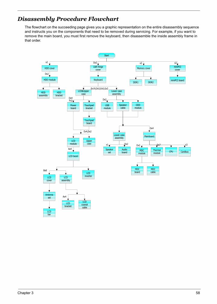
Disassembly Procedure FlowchartThe flowchart on the succeeding page gives you a graphic representation on the entire disassembly sequence and instructs you on the components that need to be removed during servicing. For example, if you want to remove the main board, you must first remove the keyboard, then disassemble the inside assembly frame in that order.
HDD cover
Start
L&R hingecover Memory cover miniPCI
cover
HDD module
HDDassembly
HDDbracket
DDR2DDR1miniPCI boardKeyboard
LCD&Uppercase
Lower caseassembly
Speakercable
USBmodule
ODDmodule
Powerboard
Touchpadbracket
Touchpadboard
LCDmodule
Uppercase
Lower caseassembly
Mainboard
LCD bezel
Speakerset
Audioboard
MDCmodule
Thermalmodule CPU Cardbus
MDCboard
MDCcableLCD
inverterLCDcover
LCDassembly
Antennaset
LCDbar
LCDbracket
LCDcoaxialcable
x2
Dx2
Dx2
Ex19,Dx3,Ex5,Gx2
x2 x2
Dx2
Dx4
Dx7 x3 Dx2 Dx2 x1
Dx4 Fx2
Ex4,Dx2
Ax4
Bx8
Ax4
Chapter 3 58
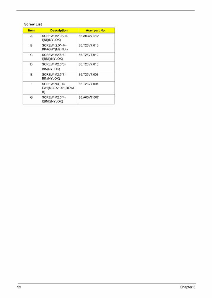
Screw ListItem Description Acer part No.
A SCREW M2.0*2.5-I(NI)(NYLOK)
86.A03V7.012
B SCREW I2.5*4M-BKAGHY(M2.5L4)
86.T25V7.013
C SCREW M2.5*6-I(BNI)(NYLOK)
86.T25V7.012
D SCREW M2.5*3-IBIN(NYLOK)
86.T23V7.010
E SCREW M2.5*7-I BIN(NYLOK)
86.T25V7.008
F SCREW NUT IO EA1(MBEA1001,REV3B)
86.T23V7.001
G SCREW M2.0*4-I(BNI)(NYLOK)
86.A03V7.007
59 Chapter 3

Removing the Battery Pack1. Release the battery lock.
2. Slide the battery latch.
3. Remove the battery pack.
Chapter 3 60
Removing the HDD Module and the miniPCI
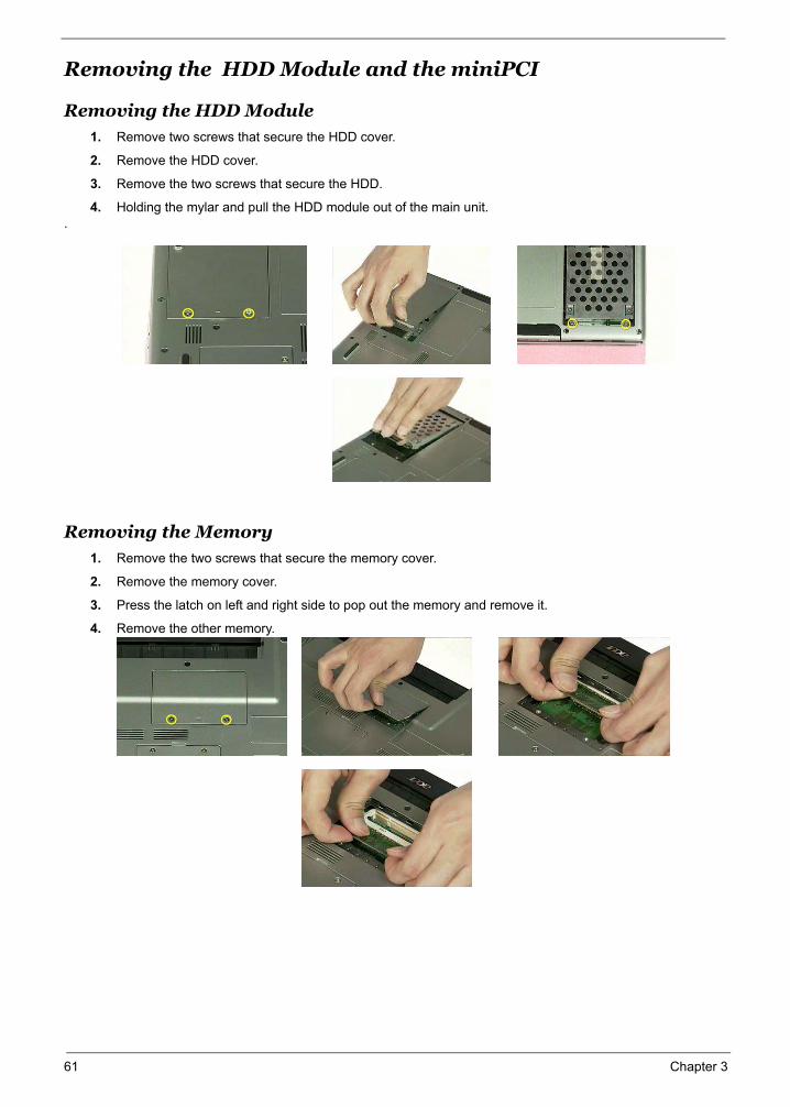
Removing the HDD Module
1. Remove two screws that secure the HDD cover.
2. Remove the HDD cover.
3. Remove the two screws that secure the HDD.
4. Holding the mylar and pull the HDD module out of the main unit..
Removing the Memory
1. Remove the two screws that secure the memory cover.
2. Remove the memory cover.
3. Press the latch on left and right side to pop out the memory and remove it.
4. Remove the other memory.
61 Chapter 3
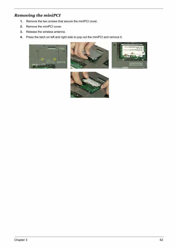
Removing the miniPCI1. Remove the two screws that secure the miniPCI cover.
2. Remove the miniPCI cover.
3. Release the wireless antenna.
4. Press the latch on left and right side to pop out the miniPCI and remove it.
Chapter 3 62
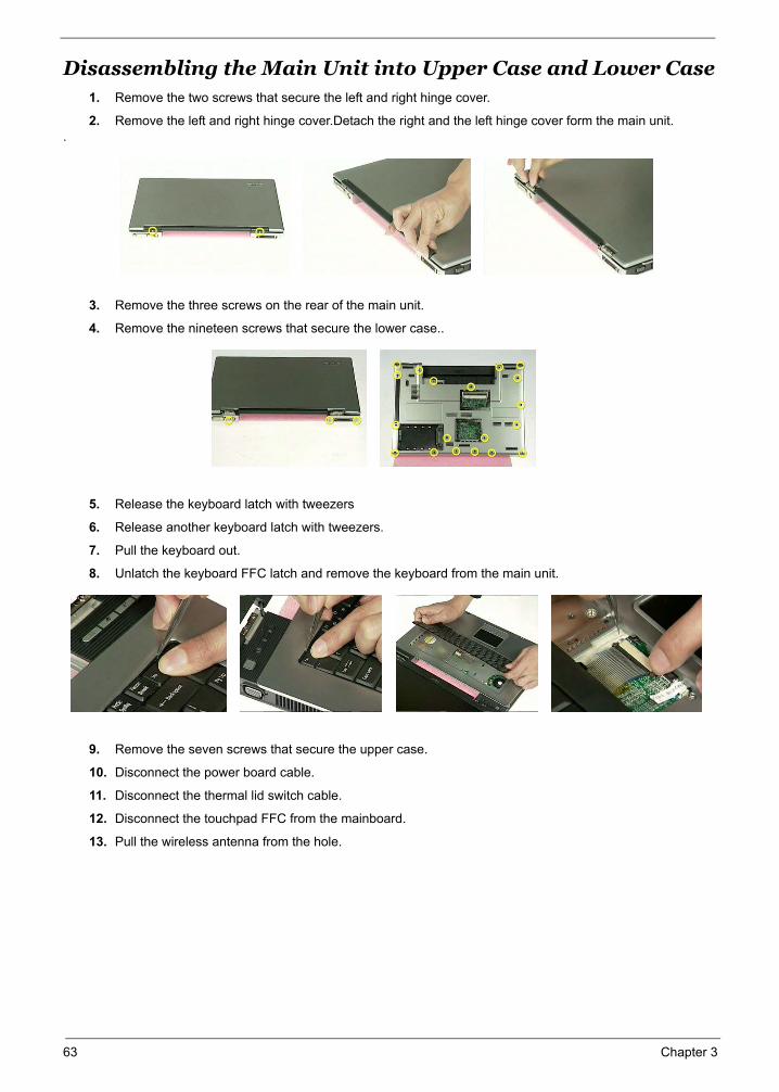
Disassembling the Main Unit into Upper Case and Lower Case1. Remove the two screws that secure the left and right hinge cover.
2. Remove the left and right hinge cover.Detach the right and the left hinge cover form the main unit..
3. Remove the three screws on the rear of the main unit.
4. Remove the nineteen screws that secure the lower case..
5. Release the keyboard latch with tweezers
6. Release another keyboard latch with tweezers.
7. Pull the keyboard out.
8. Unlatch the keyboard FFC latch and remove the keyboard from the main unit.
9. Remove the seven screws that secure the upper case.
10. Disconnect the power board cable.
11. Disconnect the thermal lid switch cable.
12. Disconnect the touchpad FFC from the mainboard.
13. Pull the wireless antenna from the hole.
63 Chapter 3

14. Close the LCD and remove the upper case from the main unit.
Chapter 3 64
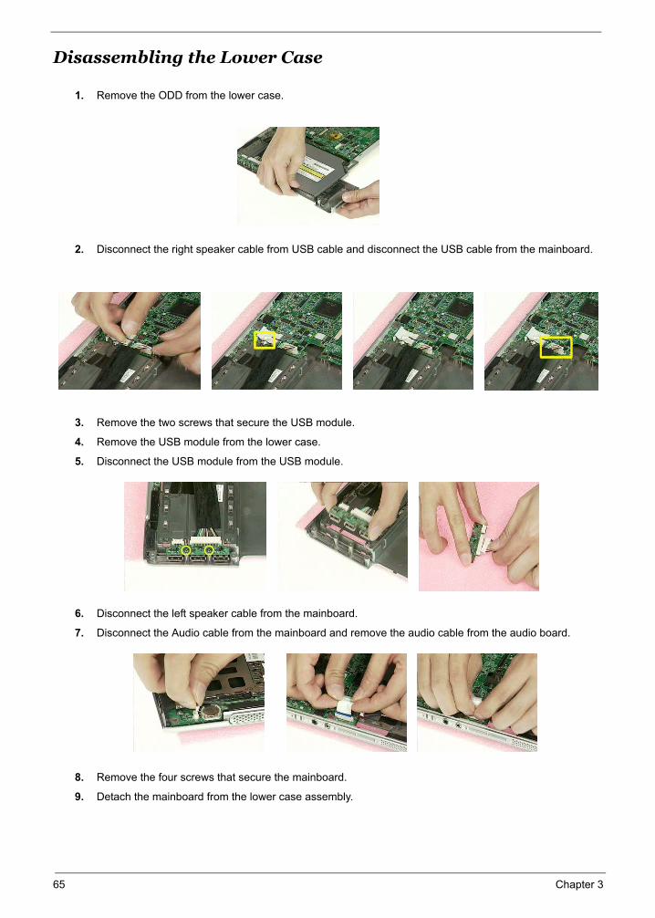
Disassembling the Lower Case
1. Remove the ODD from the lower case.
2. Disconnect the right speaker cable from USB cable and disconnect the USB cable from the mainboard.
3. Remove the two screws that secure the USB module.
4. Remove the USB module from the lower case.
5. Disconnect the USB module from the USB module.
6. Disconnect the left speaker cable from the mainboard.
7. Disconnect the Audio cable from the mainboard and remove the audio cable from the audio board.
8. Remove the four screws that secure the mainboard.
9. Detach the mainboard from the lower case assembly.
65 Chapter 3
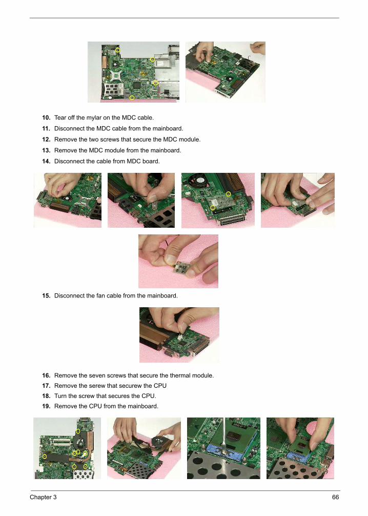
10. Tear off the mylar on the MDC cable.
11. Disconnect the MDC cable from the mainboard.
12. Remove the two screws that secure the MDC module.
13. Remove the MDC module from the mainboard.
14. Disconnect the cable from MDC board.
15. Disconnect the fan cable from the mainboard.
16. Remove the seven screws that secure the thermal module.
17. Remove the serew that securew the CPU
18. Turn the screw that secures the CPU.
19. Remove the CPU from the mainboard.
Chapter 3 66
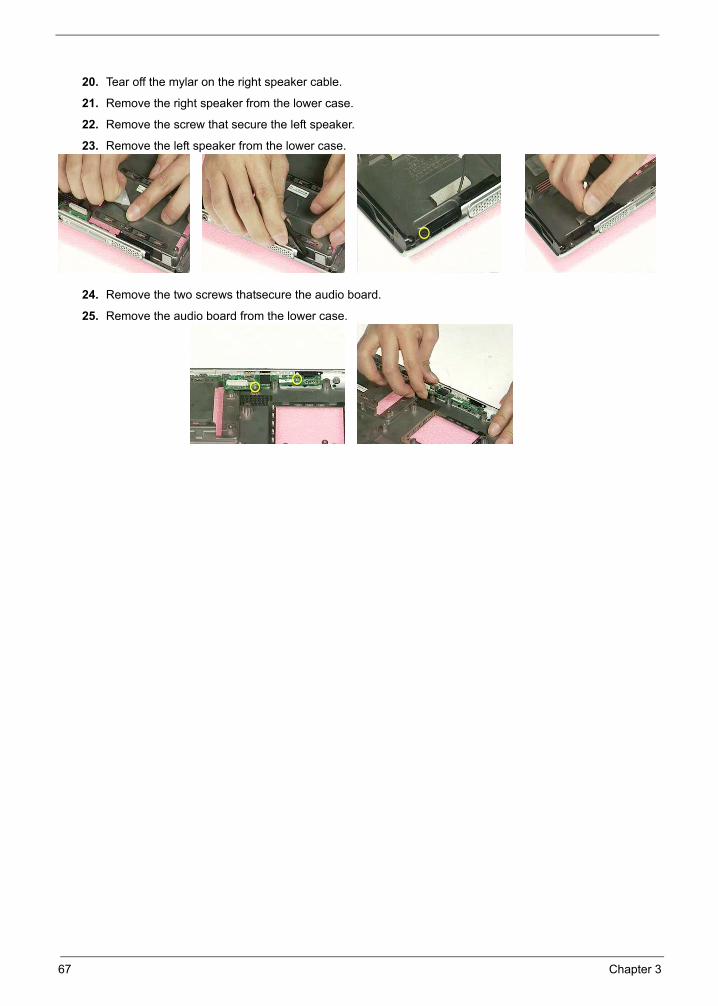
20. Tear off the mylar on the right speaker cable.
21. Remove the right speaker from the lower case.
22. Remove the screw that secure the left speaker.
23. Remove the left speaker from the lower case.
24. Remove the two screws thatsecure the audio board.
25. Remove the audio board from the lower case.
67 Chapter 3
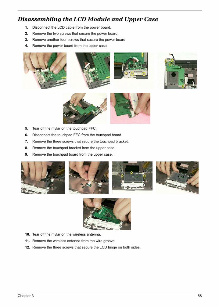
Disassembling the LCD Module and Upper Case1. Disconnect the LCD cable from the power board.
2. Remove the two screws that secure the power board.
3. Remove another four screws that secure the power board.
4. Remove the power board from the upper case.
5. Tear off the mylar on the touchpad FFC.
6. Disconnect the touchpad FFC from the touchpad board.
7. Remove the three screws that secure the touchpad bracket.
8. Remove the touchpad bracket from the upper case.
9. Remove the touchpad board from the upper case.
10. Tear off the mylar on the wireless antenna.
11. Remove the wireless antenna from the wire groove.
12. Remove the three screws that secure the LCD hinge on both sides.
Chapter 3 68
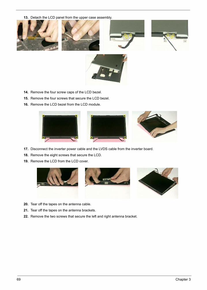
13. Detach the LCD panel from the upper case assembly.
14. Remove the four screw caps of the LCD bezel.
15. Remove the four screws that secure the LCD bezel.
16. Remove the LCD bezel from the LCD module.
17. Disconnect the inverter power cable and the LVDS cable from the inverter board.
18. Remove the eight screws that secure the LCD.
19. Remove the LCD from the LCD cover.
20. Tear off the tapes on the antenna cable.
21. Tear off the tapes on the antenna brackets.
22. Remove the two screws that secure the left and right antenna bracket.
69 Chapter 3
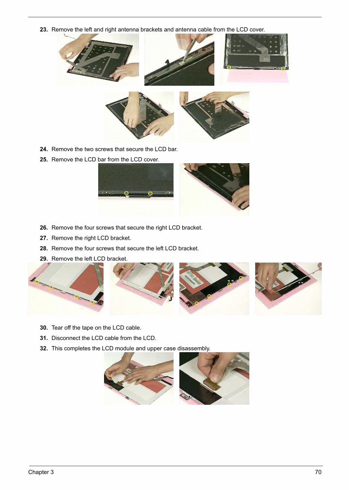
23. Remove the left and right antenna brackets and antenna cable from the LCD cover.
24. Remove the two screws that secure the LCD bar.
25. Remove the LCD bar from the LCD cover.
26. Remove the four screws that secure the right LCD bracket.
27. Remove the right LCD bracket.
28. Remove the four screws that secure the left LCD bracket.
29. Remove the left LCD bracket.
30. Tear off the tape on the LCD cable.
31. Disconnect the LCD cable from the LCD.
32. This completes the LCD module and upper case disassembly.
Chapter 3 70
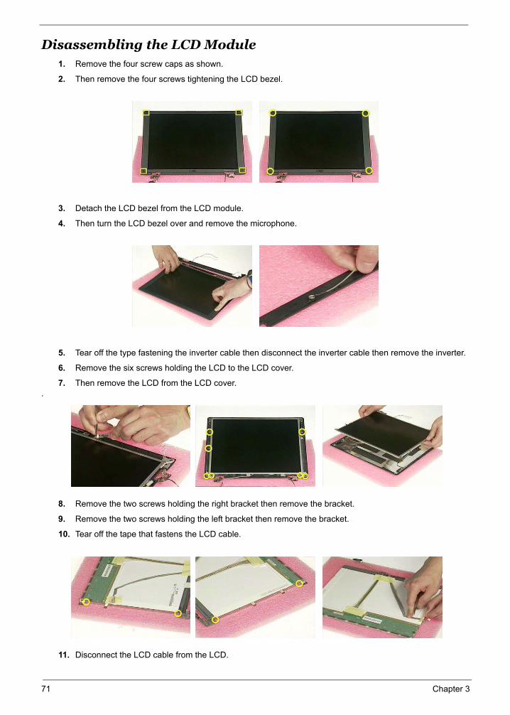
Disassembling the LCD Module1. Remove the four screw caps as shown.
2. Then remove the four screws tightening the LCD bezel.
3. Detach the LCD bezel from the LCD module.
4. Then turn the LCD bezel over and remove the microphone.
5. Tear off the type fastening the inverter cable then disconnect the inverter cable then remove the inverter.
6. Remove the six screws holding the LCD to the LCD cover.
7. Then remove the LCD from the LCD cover..
8. Remove the two screws holding the right bracket then remove the bracket.
9. Remove the two screws holding the left bracket then remove the bracket.
10. Tear off the tape that fastens the LCD cable.
11. Disconnect the LCD cable from the LCD.
71 Chapter 3
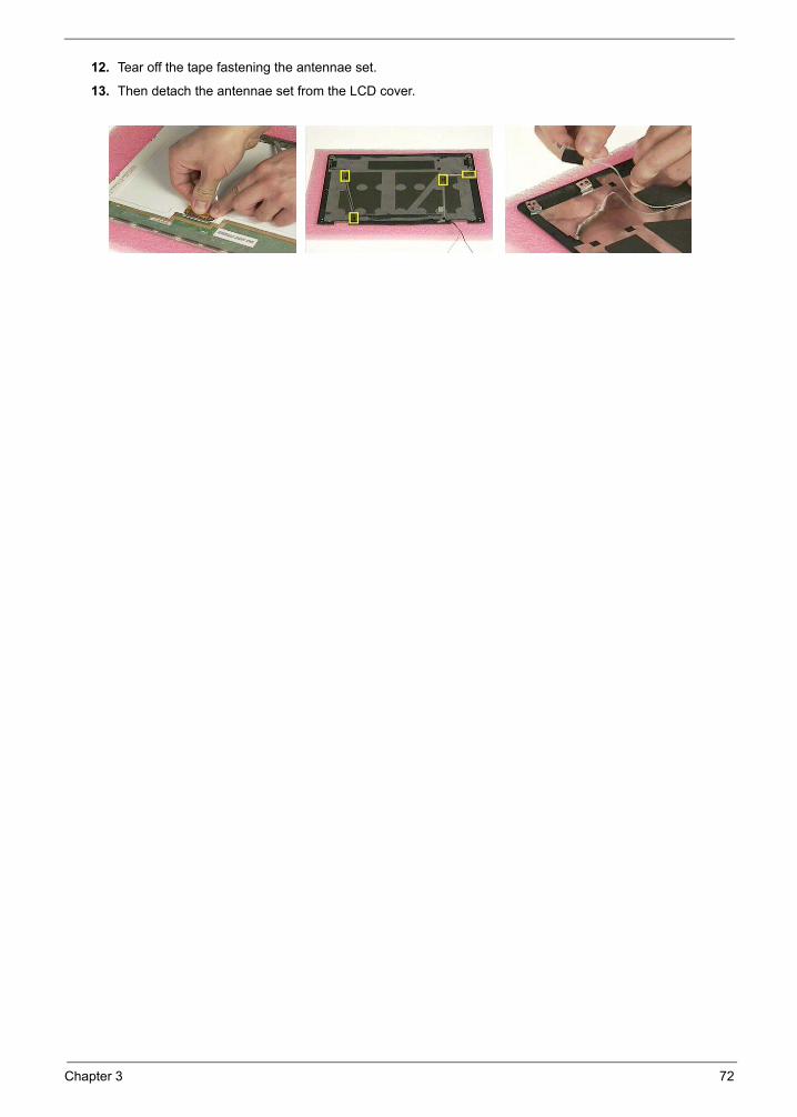
12. Tear off the tape fastening the antennae set.
13. Then detach the antennae set from the LCD cover.
Chapter 3 72
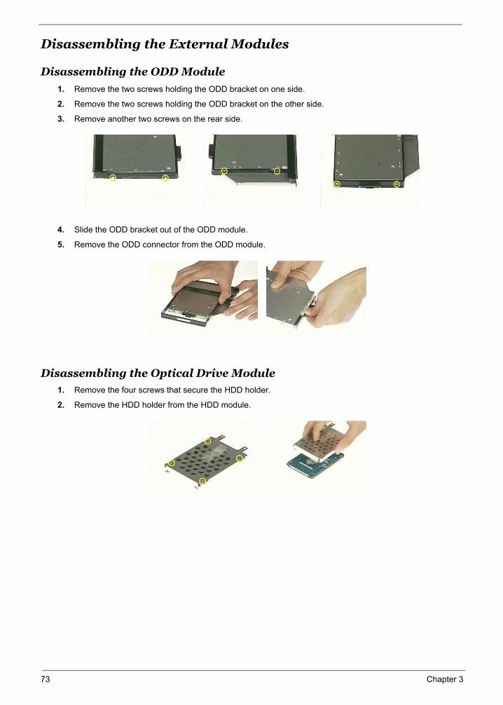
Disassembling the External Modules
Disassembling the ODD Module
1. Remove the two screws holding the ODD bracket on one side.
2. Remove the two screws holding the ODD bracket on the other side.
3. Remove another two screws on the rear side.
4. Slide the ODD bracket out of the ODD module.
5. Remove the ODD connector from the ODD module.
Disassembling the Optical Drive Module1. Remove the four screws that secure the HDD holder.
2. Remove the HDD holder from the HDD module.
73 Chapter 3
Troubleshooting
Chapter 4
Use the following procedure as a guide for computer problems.
NOTE: The diagnostic tests are intended to test only Acer products. Non-Acer products, prototype cards, or modified options can give false errors and invalid system responses.
1. Obtain the failing symptoms in as much detail as possible.
2. Verify the symptoms by attempting to re-create the failure by running the diagnostic test or by repeating the same operation.
Chapter 4 74
System Check Procedures
External Diskette Drive Check
Do the following to isolate the problem to a controller, driver, or diskette. A write-enabled, diagnostic diskette is required.
NOTE: Make sure that the diskette does not have more than one label attached to it. Multiple labels can cause damage to the drive or cause the drive to fail.
Do the following to select the test device.
1. Boot from the diagnostics diskette and start the diagnostics program.
2. See if FDD Test is passed as the program runs to FDD Test.
3. Follow the instructions in the message window.
If an error occurs with the internal diskette drive, reconnect the diskette connector on the system board.
If the error still remains:
1. Reconnect the external diskette drive/DVD-ROM module.
2. Replace the external diskette drive/CD-ROM module.
3. Replace the main board.
External CD-ROM Drive Check
Do the following to isolate the problem to a controller, drive, or CD-ROM. Make sure that the CD-ROM does not have any label attached to it. The label can cause damage to the drive or can cause the drive to fail.
Do the following to select the test device:
1. Boot from the diagnostics diskette and start the diagnostics program.
2. See if CD-ROM Test is passed when the program runs to CD-ROM Test.
3. Follow the instructions in the message window.
If an error occurs, reconnect the connector on the System board. If the error still remains:
1. Reconnect the external diskette drive/CD-ROM module.
2. Replace the external diskette drive/CD-ROM module.
3. Replace the main board.
Keyboard or Auxiliary Input Device Check
Remove the external keyboard if the internal keyboard is to be tested.
If the internal keyboard does not work or an unexpected character appears, make sure that the flexible cable extending from the keyboard is correctly seated in the connector on the system board.
If the keyboard cable connection is correct, run the Keyboard Test.
If the tests detect a keyboard problem, do the following one at a time to correct the problem. Do not replace a non-defective FRU:
1. Reconnect the keyboard cables.
2. Replace the keyboard.
3. Replace the main board.
The following auxiliary input devices are supported by this computer:
Numeric keypad
External keyboard
If any of these devices do not work, reconnect the cable connector and repeat the failing operation.
75 Chapter 4
Memory checkMemory errors might stop system operations, show error messages on the screen, or hang the system.
1. Boot from the diagnostics diskette and start the doagmpstotics program (please refer to main board.
2. Go to the diagnostic memory in the test items.
3. Press F2 in the test items.
4. Follow the instructions in the message window.NOTE: Make sure that the DIMM is fully installed into the connector. A loose connection can cause an error.
Power System Check
To verify the symptom of the problem, power on the computer using each of the following power sources:
1. Remove the battery pack.
2. Connect the power adapter and check that power is supplied.
3. Disconnect the power adapter and install the charged battery pack; then check that power is supplied by the battery pack.
If you suspect a power problem, see the appropriate power supply check in the following list:
“Check the Power Adapter” on page 77
“Check the Battery Pack” on page 78
Chapter 4 76

Check the Power AdapterUnplug the power adapter cable from the computer and measure the output voltage at the plug of the power adapter cable. See the following figure
1. If the voltage is not correct, replace the power adapter.
2. If the voltage is within the range, do the following:
Replace the System board.
If the problem is not corrected, see “Undetermined Problems” on page 88.
If the voltage is not correct, go to the next step.NOTE: An audible noise from the power adapter does not always indicate a defect.
3. If the power-on indicator does not light up, check the power cord of the power adapter for correct continuity and installation.
4. If the operational charge does not work, see “Check the Battery Pack” on page 78.
Pin 1: +19 to +20.5VPin 2: 0V, Ground
77 Chapter 4
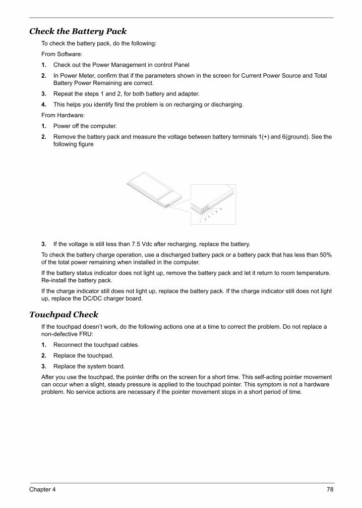
Check the Battery Pack To check the battery pack, do the following:
From Software:
1. Check out the Power Management in control Panel
2. In Power Meter, confirm that if the parameters shown in the screen for Current Power Source and Total Battery Power Remaining are correct.
3. Repeat the steps 1 and 2, for both battery and adapter.
4. This helps you identify first the problem is on recharging or discharging.
From Hardware:
1. Power off the computer.
2. Remove the battery pack and measure the voltage between battery terminals 1(+) and 6(ground). See the following figure
3. If the voltage is still less than 7.5 Vdc after recharging, replace the battery.
To check the battery charge operation, use a discharged battery pack or a battery pack that has less than 50% of the total power remaining when installed in the computer.
If the battery status indicator does not light up, remove the battery pack and let it return to room temperature. Re-install the battery pack.
If the charge indicator still does not light up, replace the battery pack. If the charge indicator still does not light up, replace the DC/DC charger board.
Touchpad Check
If the touchpad doesn’t work, do the following actions one at a time to correct the problem. Do not replace a non-defective FRU:
1. Reconnect the touchpad cables.
2. Replace the touchpad.
3. Replace the system board.
After you use the touchpad, the pointer drifts on the screen for a short time. This self-acting pointer movement can occur when a slight, steady pressure is applied to the touchpad pointer. This symptom is not a hardware problem. No service actions are necessary if the pointer movement stops in a short period of time.
Chapter 4 78

Power-On Self-Test (POST) Error Message
The POST error message index lists the error message and their possible causes. The most likely cause is listed first.
NOTE: Perform the FRU replacement or actions in the sequence shown in FRU/Action column, if the FRU replacement does not solve the problem, put the original part back in the computer. Do not replace a non-defective FRU.
This index can also help you determine the next possible FRU to be replaced when servicing a computer.
If the symptom is not listed, see “Undetermined Problems” on page 88.
The following lists the error messages that the BIOS displays on the screen and the error symptoms classified by function.
NOTE: Most of the error messages occur during POST. Some of them display information about a hardware device, e.g., the amount of memory installed. Others may indicate a problem with a device, such as the way it has been configured.
NOTE: If the system fails after you make changes in the BIOS Setup Utility menus, reset the computer, enter Setup and install Setup defaults or correct the error.
79 Chapter 4
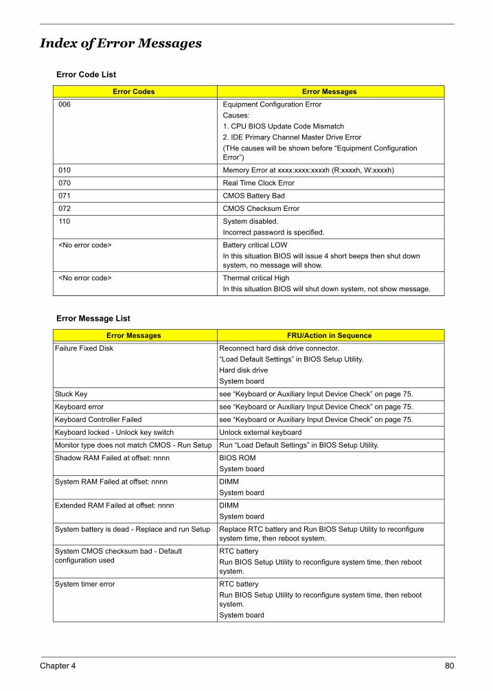
Index of Error Messages
Error Code List
Error Codes Error Messages
006 Equipment Configuration ErrorCauses:1. CPU BIOS Update Code Mismatch2. IDE Primary Channel Master Drive Error(THe causes will be shown before “Equipment Configuration Error”)
010 Memory Error at xxxx:xxxx:xxxxh (R:xxxxh, W:xxxxh)
070 Real Time Clock Error
071 CMOS Battery Bad
072 CMOS Checksum Error
110 System disabled.Incorrect password is specified.
<No error code> Battery critical LOWIn this situation BIOS will issue 4 short beeps then shut down system, no message will show.
<No error code> Thermal critical HighIn this situation BIOS will shut down system, not show message.
Error Message List
Error Messages FRU/Action in Sequence
Failure Fixed Disk Reconnect hard disk drive connector.“Load Default Settings” in BIOS Setup Utility.Hard disk driveSystem board
Stuck Key see “Keyboard or Auxiliary Input Device Check” on page 75.
Keyboard error see “Keyboard or Auxiliary Input Device Check” on page 75.
Keyboard Controller Failed see “Keyboard or Auxiliary Input Device Check” on page 75.
Keyboard locked - Unlock key switch Unlock external keyboard
Monitor type does not match CMOS - Run Setup Run “Load Default Settings” in BIOS Setup Utility.
Shadow RAM Failed at offset: nnnn BIOS ROMSystem board
System RAM Failed at offset: nnnn DIMMSystem board
Extended RAM Failed at offset: nnnn DIMMSystem board
System battery is dead - Replace and run Setup Replace RTC battery and Run BIOS Setup Utility to reconfigure system time, then reboot system.
System CMOS checksum bad - Default configuration used
RTC batteryRun BIOS Setup Utility to reconfigure system time, then reboot system.
System timer error RTC batteryRun BIOS Setup Utility to reconfigure system time, then reboot system.System board
Chapter 4 80
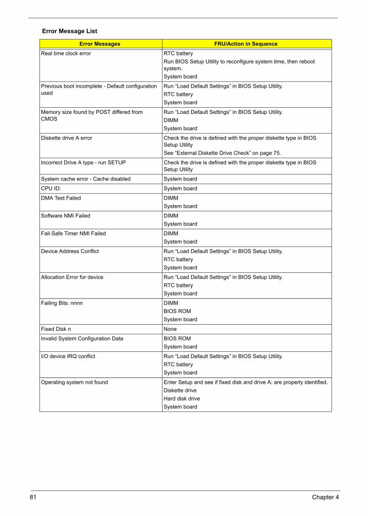
Real time clock error RTC batteryRun BIOS Setup Utility to reconfigure system time, then reboot system.System board
Previous boot incomplete - Default configuration used
Run “Load Default Settings” in BIOS Setup Utility.RTC batterySystem board
Memory size found by POST differed from CMOS
Run “Load Default Settings” in BIOS Setup Utility.DIMMSystem board
Diskette drive A error Check the drive is defined with the proper diskette type in BIOS Setup UtilitySee “External Diskette Drive Check” on page 75.
Incorrect Drive A type - run SETUP Check the drive is defined with the proper diskette type in BIOS Setup Utility
System cache error - Cache disabled System board
CPU ID: System board
DMA Test Failed DIMMSystem board
Software NMI Failed DIMMSystem board
Fail-Safe Timer NMI Failed DIMMSystem board
Device Address Conflict Run “Load Default Settings” in BIOS Setup Utility.RTC batterySystem board
Allocation Error for device Run “Load Default Settings” in BIOS Setup Utility.RTC batterySystem board
Failing Bits: nnnn DIMMBIOS ROMSystem board
Fixed Disk n None
Invalid System Configuration Data BIOS ROMSystem board
I/O device IRQ conflict Run “Load Default Settings” in BIOS Setup Utility.RTC batterySystem board
Operating system not found Enter Setup and see if fixed disk and drive A: are properly identified.Diskette driveHard disk driveSystem board
Error Message List
Error Messages FRU/Action in Sequence
81 Chapter 4
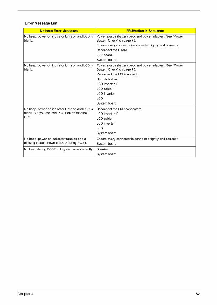
Error Message List
No beep Error Messages FRU/Action in Sequence
No beep, power-on indicator turns off and LCD is blank.
Power source (battery pack and power adapter). See “Power System Check” on page 76. Ensure every connector is connected tightly and correctly. Reconnect the DIMM.LED board.System board.
No beep, power-on indicator turns on and LCD is blank.
Power source (battery pack and power adapter). See “Power System Check” on page 76. Reconnect the LCD connectorHard disk driveLCD inverter IDLCD cableLCD InverterLCDSystem board
No beep, power-on indicator turns on and LCD is blank. But you can see POST on an external CRT.
Reconnect the LCD connectorsLCD inverter IDLCD cable LCD inverterLCDSystem board
No beep, power-on indicator turns on and a blinking cursor shown on LCD during POST.
Ensure every connector is connected tightly and correctlySystem board
No beep during POST but system runs correctly. SpeakerSystem board
Chapter 4 82
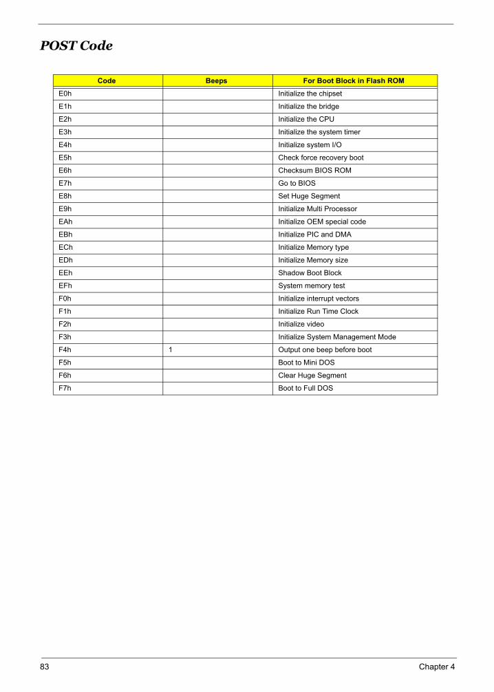
POST Code
Code Beeps For Boot Block in Flash ROM
E0h Initialize the chipset
E1h Initialize the bridge
E2h Initialize the CPU
E3h Initialize the system timer
E4h Initialize system I/O
E5h Check force recovery boot
E6h Checksum BIOS ROM
E7h Go to BIOS
E8h Set Huge Segment
E9h Initialize Multi Processor
EAh Initialize OEM special code
EBh Initialize PIC and DMA
ECh Initialize Memory type
EDh Initialize Memory size
EEh Shadow Boot Block
EFh System memory test
F0h Initialize interrupt vectors
F1h Initialize Run Time Clock
F2h Initialize video
F3h Initialize System Management Mode
F4h 1 Output one beep before boot
F5h Boot to Mini DOS
F6h Clear Huge Segment
F7h Boot to Full DOS
83 Chapter 4
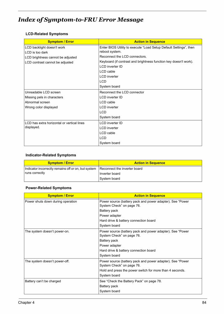
Index of Symptom-to-FRU Error Message
LCD-Related Symptoms
Symptom / Error Action in Sequence
LCD backlight doesn't workLCD is too darkLCD brightness cannot be adjustedLCD contrast cannot be adjusted
Enter BIOS Utility to execute “Load Setup Default Settings”, then reboot system.Reconnect the LCD connectors.Keyboard (if contrast and brightness function key doesn't work).LCD inverter IDLCD cableLCD inverterLCDSystem board
Unreadable LCD screen Missing pels in charactersAbnormal screen Wrong color displayed
Reconnect the LCD connectorLCD inverter IDLCD cableLCD inverterLCDSystem board
LCD has extra horizontal or vertical lines displayed.
LCD inverter IDLCD inverterLCD cableLCDSystem board
Indicator-Related Symptoms
Symptom / Error Action in Sequence
Indicator incorrectly remains off or on, but system runs correctly
Reconnect the inverter boardInverter boardSystem board
Power-Related Symptoms
Symptom / Error Action in Sequence
Power shuts down during operation Power source (battery pack and power adapter). See “Power System Check” on page 76. Battery packPower adapterHard drive & battery connection boardSystem board
The system doesn’t power-on. Power source (battery pack and power adapter). See “Power System Check” on page 76. Battery packPower adapterHard drive & battery connection boardSystem board
The system doesn’t power-off. Power source (battery pack and power adapter). See “Power System Check” on page 76. Hold and press the power switch for more than 4 seconds. System board
Battery can’t be charged See “Check the Battery Pack” on page 78. Battery packSystem board
Chapter 4 84
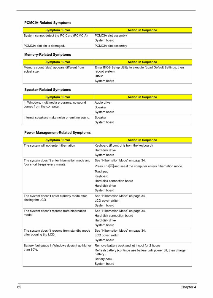
PCMCIA-Related Symptoms
Symptom / Error Action in Sequence
System cannot detect the PC Card (PCMCIA) PCMCIA slot assemblySystem board
PCMCIA slot pin is damaged. PCMCIA slot assembly
Memory-Related Symptoms
Symptom / Error Action in Sequence
Memory count (size) appears different from actual size.
Enter BIOS Setup Utility to execute “Load Default Settings, then reboot system.DIMMSystem board
Speaker-Related Symptoms
Symptom / Error Action in Sequence
In Windows, multimedia programs, no sound comes from the computer.
Audio driverSpeakerSystem board
Internal speakers make noise or emit no sound. SpeakerSystem board
Power Management-Related Symptoms
Symptom / Error Action in Sequence
The system will not enter hibernation Keyboard (if control is from the keyboard)Hard disk driveSystem board
The system doesn't enter hibernation mode and four short beeps every minute.
See “Hibernation Mode” on page 34.
Press Fn+oand see if the computer enters hibernation mode.
TouchpadKeyboardHard disk connection boardHard disk driveSystem board
The system doesn’t enter standby mode after closing the LCD
See “Hibernation Mode” on page 34.LCD cover switchSystem board
The system doesn't resume from hibernation mode.
See “Hibernation Mode” on page 34.Hard disk connection boardHard disk driveSystem board
The system doesn't resume from standby mode after opening the LCD.
See “Hibernation Mode” on page 34.LCD cover switchSystem board
Battery fuel gauge in Windows doesn’t go higher than 90%.
Remove battery pack and let it cool for 2 hoursRefresh battery (continue use battery until power off, then charge battery)Battery packSystem board
85 Chapter 4
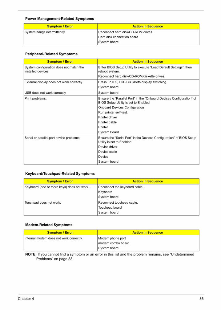
NOTE: If you cannot find a symptom or an error in this list and the problem remains, see “Undetermined Problems” on page 88.
System hangs intermittently. Reconnect hard disk/CD-ROM drives. Hard disk connection boardSystem board
Peripheral-Related Symptoms
Symptom / Error Action in Sequence
System configuration does not match the installed devices.
Enter BIOS Setup Utility to execute “Load Default Settings”, then reboot system.Reconnect hard disk/CD-ROM/diskette drives.
External display does not work correctly. Press Fn+F5, LCD/CRT/Both display switchingSystem board
USB does not work correctly System board
Print problems. Ensure the “Parallel Port” in the “Onboard Devices Configuration” of BIOS Setup Utility is set to Enabled.Onboard Devices ConfigurationRun printer self-test.Printer driverPrinter cablePrinterSystem Board
Serial or parallel port device problems. Ensure the “Serial Port” in the Devices Configuration” of BIOS Setup Utility is set to Enabled.Device driverDevice cableDeviceSystem board
Keyboard/Touchpad-Related Symptoms
Symptom / Error Action in Sequence
Keyboard (one or more keys) does not work. Reconnect the keyboard cable.KeyboardSystem board
Touchpad does not work. Reconnect touchpad cable.Touchpad boardSystem board
Modem-Related Symptoms
Symptom / Error Action in Sequence
Internal modem does not work correctly. Modem phone portmodem combo boardSystem board
Power Management-Related Symptoms
Symptom / Error Action in Sequence
Chapter 4 86
Intermittent ProblemsIntermittent system hang problems can be caused by a variety of reasons that have nothing to do with a hardware defect, such as: cosmic radiation, electrostatic discharge, or software errors. FRU replacement should be considered only when a recurring problem exists.
When analyzing an intermittent problem, do the following:
1. Run the advanced diagnostic test for the system board in loop mode at least 10 times.
2. If no error is detected, do not replace any FRU.
3. If any error is detected, replace the FRU. Rerun the test to verify that there are no more errors.
87 Chapter 4
Undetermined ProblemsThe diagnostic problems does not identify which adapter or device failed, which installed devices are incorrect, whether a short circuit is suspected, or whether the system is inoperative.
Follow these procedures to isolate the failing FRU (do not isolate non-defective FRU).
NOTE: Verify that all attached devices are supported by the computer.
NOTE: Verify that the power supply being used at the time of the failure is operating correctly. (See “Power System Check” on page 76):
1. Power-off the computer.
2. Visually check them for damage. If any problems are found, replace the FRU.
3. Remove or disconnect all of the following devices:
Non-Acer devices
Printer, mouse, and other external devices
Battery pack
Hard disk drive
DIMM
CD-ROM/Diskette drive Module
PC Cards
4. Power-on the computer.
5. Determine if the problem has changed.
6. If the problem does not recur, reconnect the removed devices one at a time until you find the failing FRU.
7. If the problem remains, replace the following FRU one at a time. Do not replace a non-defective FRU:
System board
LCD assembly
Chapter 4 88
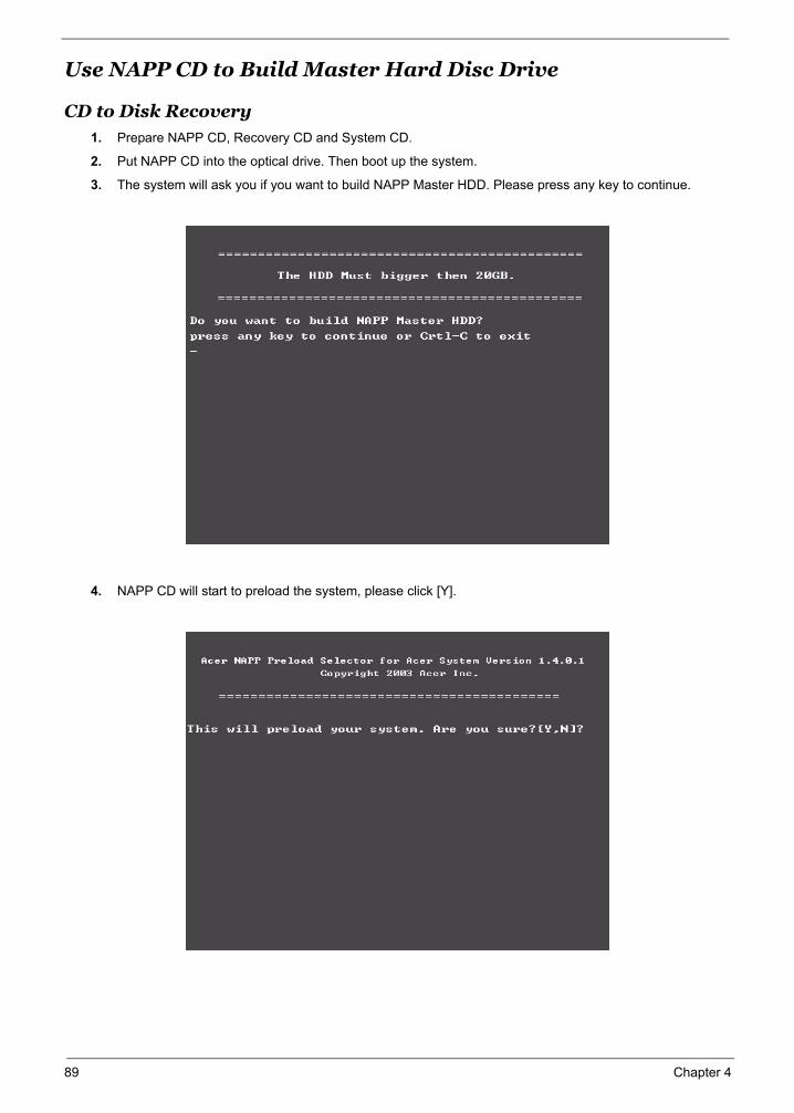
Use NAPP CD to Build Master Hard Disc Drive
CD to Disk Recovery
1. Prepare NAPP CD, Recovery CD and System CD.
2. Put NAPP CD into the optical drive. Then boot up the system.
3. The system will ask you if you want to build NAPP Master HDD. Please press any key to continue.
4. NAPP CD will start to preload the system, please click [Y].
89 Chapter 4

5. Select CD to Disk Revocery.
6. Put the Recovery CD to the optical drive. This step is to create image files to the system, you do not have to put the Recovery CD to the optical drive in order. Place one Recovery CD to the drive at one time till you finish all Recovery CDs.
After you place the Recovery CD to the optical drive, you will see the display below.
Chapter 4 90
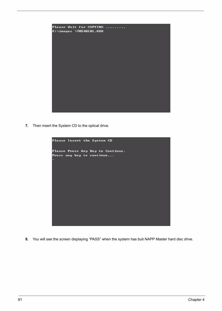
7. Then insert the System CD to the optical drive.
8. You will see the screen displaying “PASS” when the system has buit NAPP Master hard disc drive.
91 Chapter 4
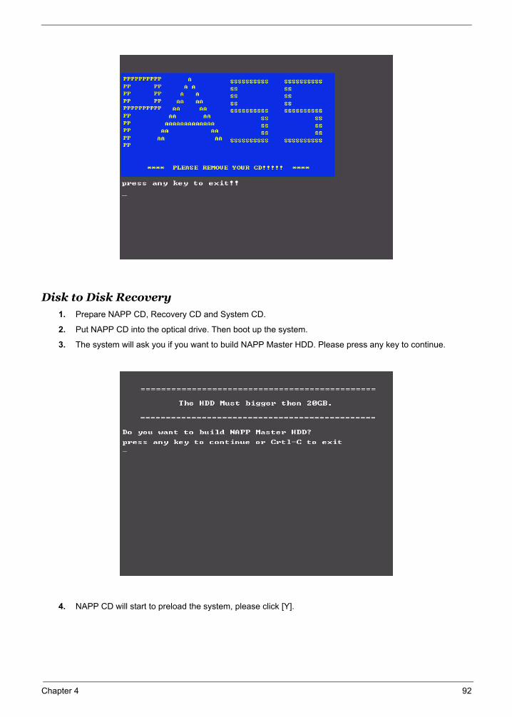
Disk to Disk Recovery1. Prepare NAPP CD, Recovery CD and System CD.
2. Put NAPP CD into the optical drive. Then boot up the system.
3. The system will ask you if you want to build NAPP Master HDD. Please press any key to continue.
4. NAPP CD will start to preload the system, please click [Y].
Chapter 4 92

5. Select Disk to Disk Recovery. Then choose Single Language or Multi-Languages Recovery.NOTE: For Multi-Languages Recovery, not more than five languages could be loaded to the system.
6. Put the Recovery CD to the optical drive. This step is to create image files to the system, you do not have to put the Recovery CD to the optical drive in order. Place one Recovery CD to the drive at one time till you finish all Recovery CDs.
93 Chapter 4
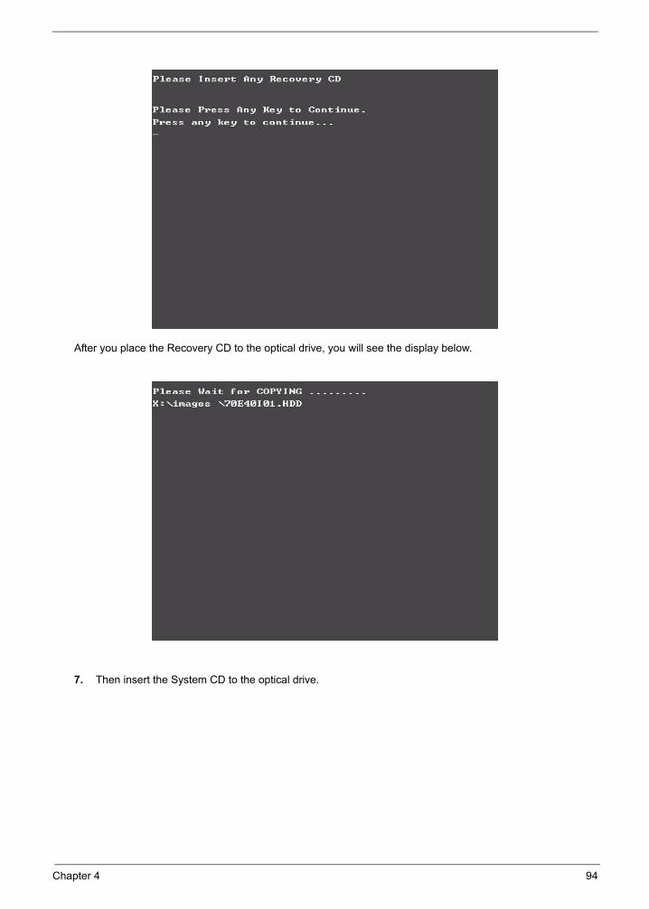
After you place the Recovery CD to the optical drive, you will see the display below.
7. Then insert the System CD to the optical drive.
Chapter 4 94
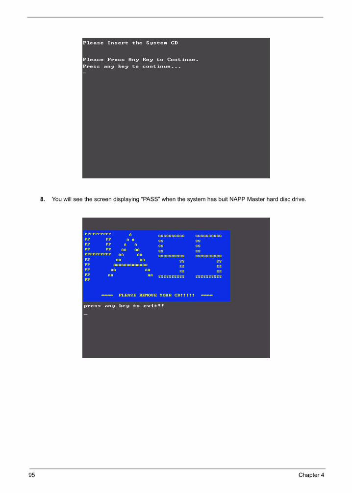
8. You will see the screen displaying “PASS” when the system has buit NAPP Master hard disc drive.
95 Chapter 4

Jumper and Connector Locations
Chapter 5
Top View
Chapter 5 96

Rear View
97 Chapter 5
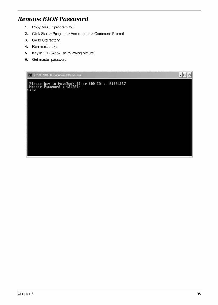
Remove BIOS Password1. Copy MastID program to C
2. Click Start > Program > Accessories > Command Prompt
3. Go to C:directory
4. Run mastid.exe
5. Key in “01234567” as following picture
6. Get master password
Chapter 5 98
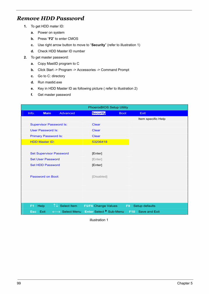
Remove HDD Password1. To get HDD mater ID:
a. Power on system
b. Press “F2” to enter CMOS
c. Use right arrow button to move to “Security” (refer to illustration 1)
d. Check HDD Master ID number
2. To get master password:
a. Copy MastID program to C
b. Click Start -> Program -> Accessories -> Command Prompt
c. Go to C: directory
d. Run mastid.exe
e. Key in HDD Master ID as following picture ( refer to illustration 2)
f. Get master password
illustration 1
PhoenixBIOS Setup Utility
Info. Main Advanced Security Boot Exit
Item specific Help
Supervisor Password Is: Clear
User Password Is: Clear
Primary Password Is: Clear
HDD Master ID: 53206418
Set Supervisor Password [Enter]
Set User Password [Enter]
Set HDD Password [Enter]
Password on Boot: [Disabled]
F1 Help Select Item F5/F6 Change Values F9 Setup defaults
Esc Exit Select Menu Enter Select Sub-Menu F10 Save and Exit
99 Chapter 5
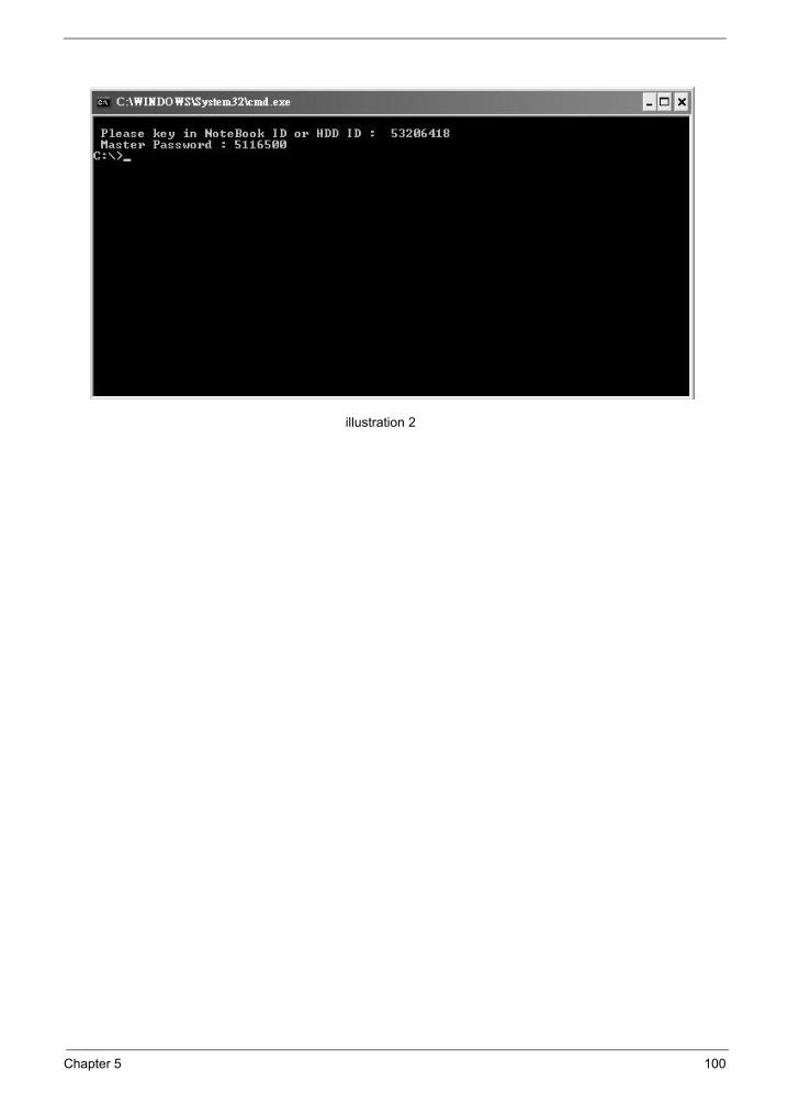
illustration 2
Chapter 5 100
FRU (Field Replaceable Unit) List
Chapter 6
This chapter gives you the FRU (Field Replaceable Unit) listing in global configurations of Ferrari 4000 series
products. Refer to this chapter whenever ordering for parts to repair or for RMA (Return Merchandise
Authorization).
Please note that WHEN ORDERING FRU PARTS, you should check the most up-to-date information available
on your regional web or channel. For whatever reasons a part number change is made, it will not be noted on
the printed Service Guide. For ACER AUTHORIZED SERVICE PROVIDERS, your Acer office may have a
DIFFERENT part number code from those given in the FRU list of this printed Service Guide. You MUST use
the local FRU list provided by your regional Acer office to order FRU parts for repair and service of customer
machines.
NOTE: To scrap or to return the defective parts, you should follow the local government ordinance or regulations on how to dispose it properly, or follow the rules set by your regional Acer office on how to return it.
Chapter 6 101
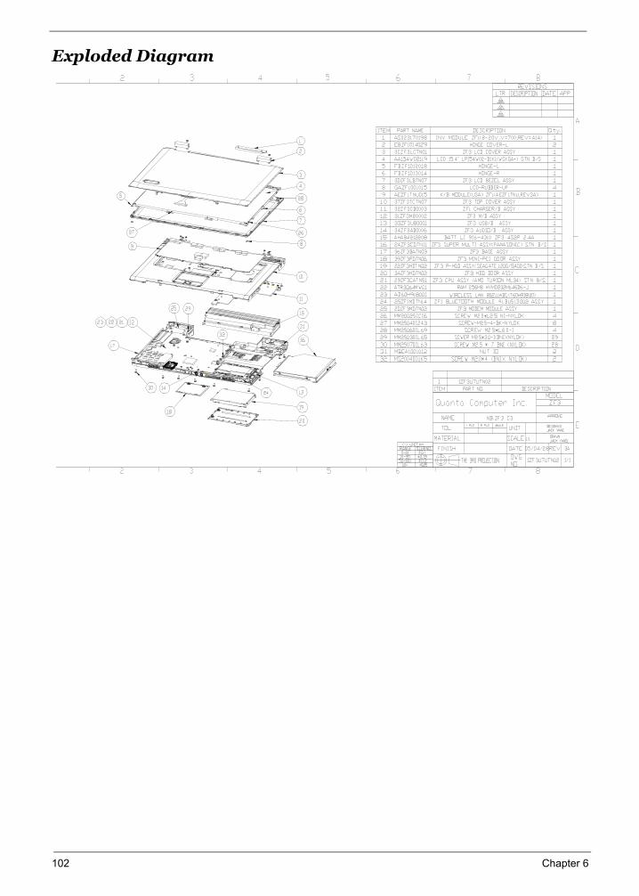
Exploded Diagram
102 Chapter 6
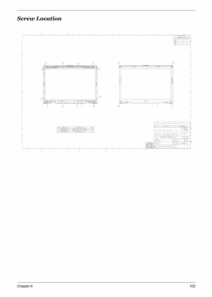
Chapter 6 103
Screw Location
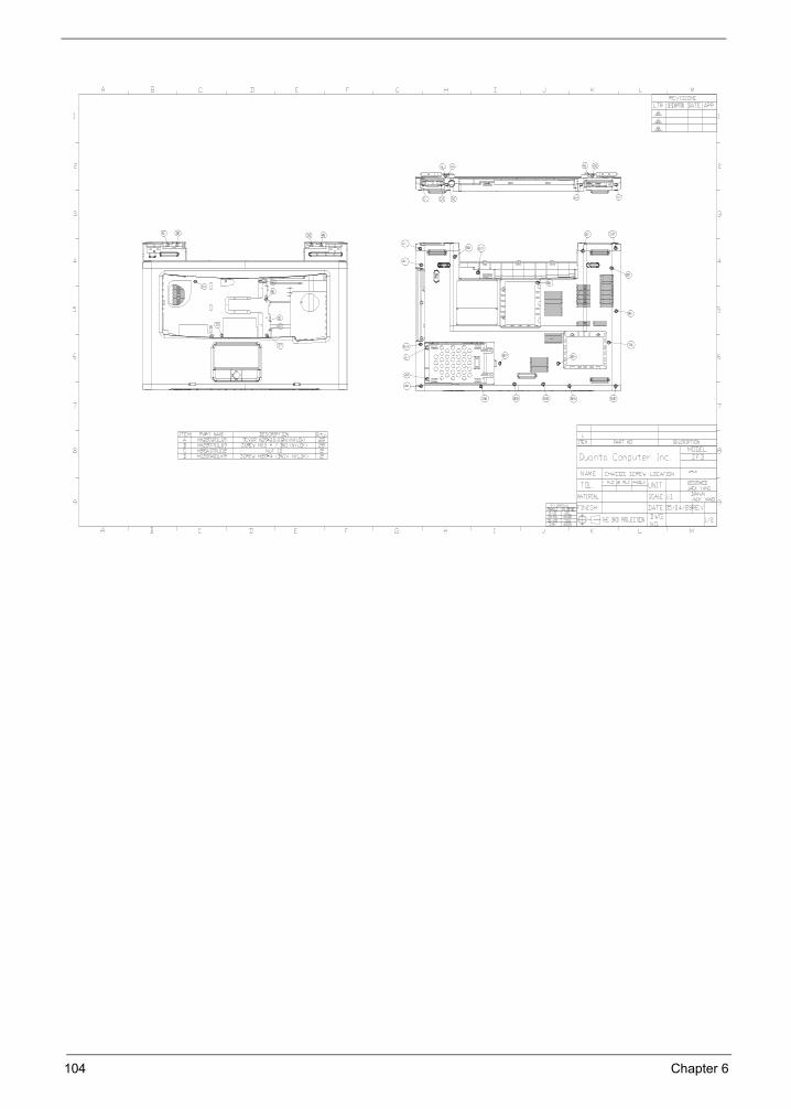
104 Chapter 6
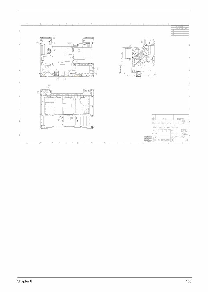
Chapter 6 105
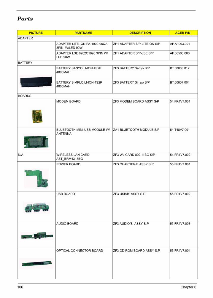
Parts
PICTURE PARTNAME DESCRIPTION ACER P/N
ADAPTER
ADAPTER LITE- ON PA-1900-05QA 3PIN W/LED 90W
ZP1 ADAPTER S/P-LITE-ON S/P AP.A1003.001
ADAPTER LSE 0202C1990 3PIN W/LED 90W
ZP1 ADAPTER S/P-LSE S/P AP.06503.006
BATTERY
BATTERY SANYO LI-ION 4S2P 4800MAH
ZF3 BATTERY Sanyo S/P BT.00803.012
BATTERY SIMPLO LI-ION 4S2P 4800MAH
ZF3 BATTERY Simpo S/P BT.00807.004
BOARDS
MODEM BOARD ZF3 MODEM BOARD ASSY S/P 54.FR4V7.001
BLUETOOTH MINI-USB MODULE W/ANTENNA
ZA1 BLUETOOTH MODULE S/P 54.T48V7.001
N/A WIRELESS LAN CARD ABT_BRM4318BG
ZF3 WL CARD 802.11BG S/P 54.FR4V7.002
POWER BOARD ZF3 CHARGER/B ASSY S.P. 55.FR4V7.001
USB BOARD ZF3 USB/B ASSY S.P. 55.FR4V7.002
AUDIO BOARD ZF3 AUDIO/B ASSY S.P. 55.FR4V7.003
OPTICAL CONNECTOR BOARD ZF3 CD-ROM BOARD ASSY S.P. 55.FR4V7.004
106 Chapter 6
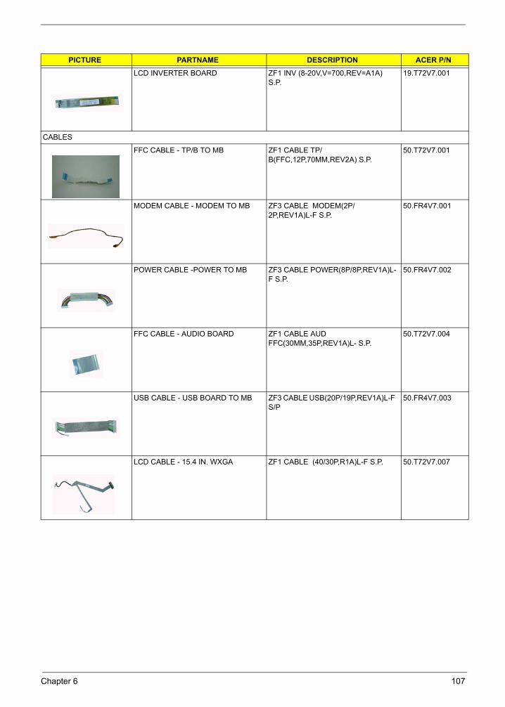
LCD INVERTER BOARD ZF1 INV (8-20V,V=700,REV=A1A) S.P.
19.T72V7.001
CABLES
FFC CABLE - TP/B TO MB ZF1 CABLE TP/B(FFC,12P,70MM,REV2A) S.P.
50.T72V7.001
MODEM CABLE - MODEM TO MB ZF3 CABLE MODEM(2P/2P,REV1A)L-F S.P.
50.FR4V7.001
POWER CABLE -POWER TO MB ZF3 CABLE POWER(8P/8P,REV1A)L-F S.P.
50.FR4V7.002
FFC CABLE - AUDIO BOARD ZF1 CABLE AUD FFC(30MM,35P,REV1A)L- S.P.
50.T72V7.004
USB CABLE - USB BOARD TO MB ZF3 CABLE USB(20P/19P,REV1A)L-F S/P
50.FR4V7.003
LCD CABLE - 15.4 IN. WXGA ZF1 CABLE (40/30P,R1A)L-F S.P. 50.T72V7.007
PICTURE PARTNAME DESCRIPTION ACER P/N
Chapter 6 107
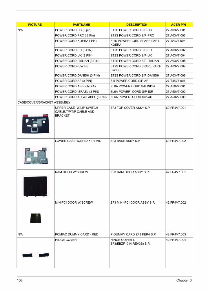
N/A POWER CORD US (3 pin) ET2S POWER CORD S/P-US 27.A03V7.001
POWER CORD PRC ( 3 Pin) ET2S POWER CORD S/P-PRC 27.A03V7.003
POWER CORD KOERA ( Pin) ZI1S POWER CORD SPARE PART-KOERA
27.T23V7.006
POWER CORD EU (3 PIN) ET2S POWER CORD S/P-EU 27.A03V7.002
POWER CORD UK (3 PIN) ET2S POWER CORD S/P-UK 27.A03V7.004
POWER CORD ITALIAN (3 PIN) ET2S POWER CORD S/P-ITALIAN 27.A03V7.005
POWER CORD- SWISS ET2S POWER CORD SPARE PART-SWISS
27.A03V7.007
POWER CORD DANISH (3 PIN) ET2S POWER CORD S/P-DANISH 27.A03V7.006
POWER CORD AF (3 PIN) ZI5 POWER CORD S/P-AF 27.T48V7.001
POWER CORD AF-S (INDIA) ZL6A POWER CORD S/P INDIA 27.A50V7.001
POWER CORD ISRAEL (3 PIN) ZL6A POWER CORD S/P-ISR 27.A50V7.002
POWER CORD AU W/LABEL (3 PIN) ZL6A POWER CORD S/P-AU 27.A50V7.003
CASE/COVER/BRACKET ASSEMBLY
UPPER CASE W/LIP SWITCH CABLE,T/P,T/P CABLE AND BRACKET
ZF3 TOP COVER ASSY S.P. 60.FR4V7.001
LOWER CASE W/SPEAKER,MIC ZF3 BASE ASSY S.P. 60.FR4V7.002
RAM DOOR W/SCREW ZF3 RAM DOOR ASSY S.P. 42.FR4V7.001
MINIPCI DOOR W/SCREW ZF3 MINI-PCI DOOR ASSY S.P. 42.FR4V7.002
N/A PCMIAC DUMMY CARD - RED P-DUMMY CARD ZF3 FER4 S.P. 42.FR4V7.003
HINGE COVER HINGE COVER-L ZF3(EBZF1014,REV3B) S.P.
42.FR4V7.004
PICTURE PARTNAME DESCRIPTION ACER P/N
108 Chapter 6
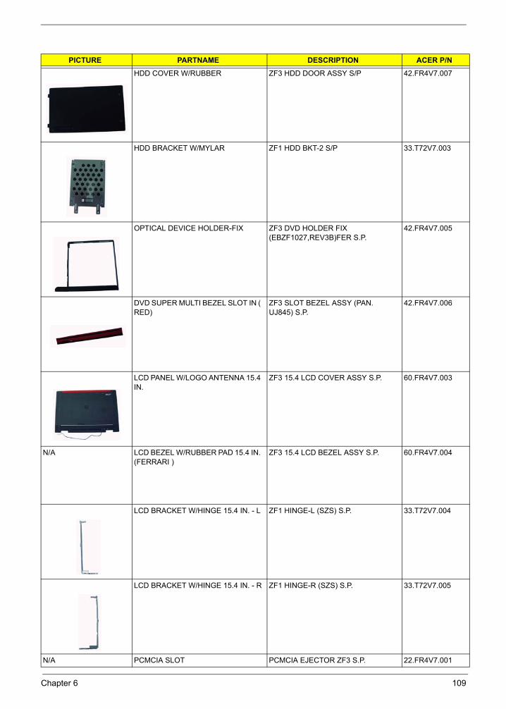
HDD COVER W/RUBBER ZF3 HDD DOOR ASSY S/P 42.FR4V7.007
HDD BRACKET W/MYLAR ZF1 HDD BKT-2 S/P 33.T72V7.003
OPTICAL DEVICE HOLDER-FIX ZF3 DVD HOLDER FIX (EBZF1027,REV3B)FER S.P.
42.FR4V7.005
DVD SUPER MULTI BEZEL SLOT IN ( RED)
ZF3 SLOT BEZEL ASSY (PAN. UJ845) S.P.
42.FR4V7.006
LCD PANEL W/LOGO ANTENNA 15.4 IN.
ZF3 15.4 LCD COVER ASSY S.P. 60.FR4V7.003
N/A LCD BEZEL W/RUBBER PAD 15.4 IN. (FERRARI )
ZF3 15.4 LCD BEZEL ASSY S.P. 60.FR4V7.004
LCD BRACKET W/HINGE 15.4 IN. - L ZF1 HINGE-L (SZS) S.P. 33.T72V7.004
LCD BRACKET W/HINGE 15.4 IN. - R ZF1 HINGE-R (SZS) S.P. 33.T72V7.005
N/A PCMCIA SLOT PCMCIA EJECTOR ZF3 S.P. 22.FR4V7.001
PICTURE PARTNAME DESCRIPTION ACER P/N
Chapter 6 109
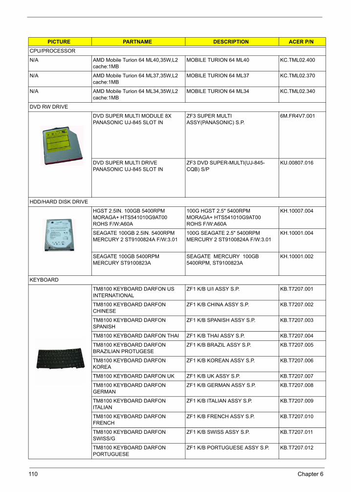
CPU/PROCESSOR
N/A AMD Mobile Turion 64 ML40,35W,L2 cache:1MB
MOBILE TURION 64 ML40 KC.TML02.400
N/A AMD Mobile Turion 64 ML37,35W,L2 cache:1MB
MOBILE TURION 64 ML37 KC.TML02.370
N/A AMD Mobile Turion 64 ML34,35W,L2 cache:1MB
MOBILE TURION 64 ML34 KC.TML02.340
DVD RW DRIVE
DVD SUPER MULTI MODULE 8X PANASONIC UJ-845 SLOT IN
ZF3 SUPER MULTI ASSY(PANASONIC) S.P.
6M.FR4V7.001
DVD SUPER MULTI DRIVE PANASONIC UJ-845 SLOT IN
ZF3 DVD SUPER-MULTI(UJ-845-CQB) S/P
KU.00807.016
HDD/HARD DISK DRIVE
HGST 2.5IN. 100GB 5400RPM MORAGA+ HTS541010G9AT00 ROHS F/W:A60A
100G HGST 2.5" 5400RPM MORAGA+ HTS541010G9AT00 ROHS F/W:A60A
KH.10007.004
SEAGATE 100GB 2.5IN. 5400RPM MERCURY 2 ST9100824A F/W:3.01
100G SEAGATE 2.5" 5400RPM MERCURY 2 ST9100824A F/W:3.01
KH.10001.004
SEAGATE 100GB 5400RPM MERCURY ST9100823A
SEAGATE MERCURY 100GB 5400RPM, ST9100823A
KH.10001.002
KEYBOARD
TM8100 KEYBOARD DARFON US INTERNATIONAL
ZF1 K/B U/I ASSY S.P. KB.T7207.001
TM8100 KEYBOARD DARFON CHINESE
ZF1 K/B CHINA ASSY S.P. KB.T7207.002
TM8100 KEYBOARD DARFON SPANISH
ZF1 K/B SPANISH ASSY S.P. KB.T7207.003
TM8100 KEYBOARD DARFON THAI ZF1 K/B THAI ASSY S.P. KB.T7207.004
TM8100 KEYBOARD DARFON BRAZILIAN PROTUGESE
ZF1 K/B BRAZIL ASSY S.P. KB.T7207.005
TM8100 KEYBOARD DARFON KOREA
ZF1 K/B KOREAN ASSY S.P. KB.T7207.006
TM8100 KEYBOARD DARFON UK ZF1 K/B UK ASSY S.P. KB.T7207.007
TM8100 KEYBOARD DARFON GERMAN
ZF1 K/B GERMAN ASSY S.P. KB.T7207.008
TM8100 KEYBOARD DARFON ITALIAN
ZF1 K/B ITALIAN ASSY S.P. KB.T7207.009
TM8100 KEYBOARD DARFON FRENCH
ZF1 K/B FRENCH ASSY S.P. KB.T7207.010
TM8100 KEYBOARD DARFON SWISS/G
ZF1 K/B SWISS ASSY S.P. KB.T7207.011
TM8100 KEYBOARD DARFON PORTUGUESE
ZF1 K/B PORTUGUESE ASSY S.P. KB.T7207.012
PICTURE PARTNAME DESCRIPTION ACER P/N
110 Chapter 6
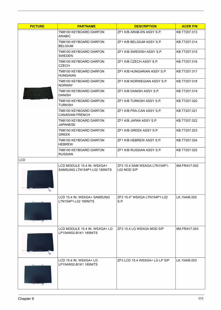
TM8100 KEYBOARD DARFON ARABIC
ZF1 K/B ARAB-EN ASSY S.P. KB.T7207.013
TM8100 KEYBOARD DARFON BELGIUM
ZF1 K/B BELGIUM ASSY S.P. KB.T7207.014
TM8100 KEYBOARD DARFON SWEDEN
ZF1 K/B SWEDISH ASSY S.P. KB.T7207.015
TM8100 KEYBOARD DARFON CZECH
ZF1 K/B CZECH ASSY S.P. KB.T7207.016
TM8100 KEYBOARD DARFON HUNGAIAN
ZF1 K/B HUNGARIAN ASSY S.P. KB.T7207.017
TM8100 KEYBOARD DARFON NORWAY
ZF1 K/B NORWEGIAN ASSY S.P. KB.T7207.018
TM8100 KEYBOARD DARFON DANISH
ZF1 K/B DANISH ASSY S.P. KB.T7207.019
TM8100 KEYBOARD DARFON TURKISH
ZF1 K/B TURKISH ASSY S.P. KB.T7207.020
TM8100 KEYBOARD DARFON CANADIAN FRENCH
ZF1 K/B FRA-CAN ASSY S.P. KB.T7207.021
TM8100 KEYBOARD DARFON JAPANESE
ZF1 K/B JAPAN ASSY S.P. KB.T7207.022
TM8100 KEYBOARD DARFON GREEK
ZF1 K/B GREEK ASSY S.P. KB.T7207.023
TM8100 KEYBOARD DARFON HEBREW
ZF1 K/B HEBREW ASSY S.P. KB.T7207.024
TM8100 KEYBOARD DARFON RUSSIAN
ZF1 K/B RUSSIAN ASSY S.P. KB.T7207.025
LCD
LCD MODULE 15.4 IN. WSXGA+ SAMSUNG LTN154P1-L02 185NITS
ZF3 15.4 SAM WSXGA LTN154P1-L02 MOD S/P
6M.FR4V7.002
LCD 15.4 IN. WSXGA+ SAMSUNG LTN154P1-L02 185NITS
ZF3 15.4" WSXGA LTN154P1-L02 S.P.
LK.15406.002
LCD MODULE 15.4 IN. WSXGA+ LG LP154W02-B1K1 185NITS
ZF3 15.4 LG WSXGA MOD S/P 6M.FR4V7.003
LCD 15.4 IN. WSXGA+ LG LP154W02-B1K1 185NITS
ZF3 LCD 15.4 WSXGA+ LG LP S/P LK.15408.003
PICTURE PARTNAME DESCRIPTION ACER P/N
Chapter 6 111
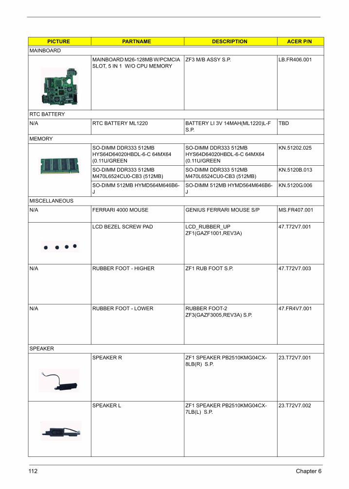
MAINBOARD
MAINBOARD M26-128MB W/PCMCIA SLOT, 5 IN 1 W/O CPU MEMORY
ZF3 M/B ASSY S.P. LB.FR406.001
RTC BATTERY
N/A RTC BATTERY ML1220 BATTERY LI 3V 14MAH(ML1220)L-F S.P.
TBD
MEMORY
SO-DIMM DDR333 512MB HYS64D64020HBDL-6-C 64MX64 (0.11U/GREEN
SO-DIMM DDR333 512MB HYS64D64020HBDL-6-C 64MX64 (0.11U/GREEN
KN.51202.025
SO-DIMM DDR333 512MB M470L6524CU0-CB3 (512MB)
SO-DIMM DDR333 512MB M470L6524CU0-CB3 (512MB)
KN.5120B.013
SO-DIMM 512MB HYMD564M646B6-J
SO-DIMM 512MB HYMD564M646B6-J
KN.5120G.006
MISCELLANEOUS
N/A FERRARI 4000 MOUSE GENIUS FERRARI MOUSE S/P MS.FR407.001
LCD BEZEL SCREW PAD LCD_RUBBER_UP ZF1(GAZF1001,REV3A)
47.T72V7.001
N/A RUBBER FOOT - HIGHER ZF1 RUB FOOT S.P. 47.T72V7.003
N/A RUBBER FOOT - LOWER RUBBER FOOT-2 ZF3(GAZF3005,REV3A) S.P.
47.FR4V7.001
SPEAKER
SPEAKER R ZF1 SPEAKER PB2510KMG04CX-8LB(R) S.P.
23.T72V7.001
SPEAKER L ZF1 SPEAKER PB2510KMG04CX-7LB(L) S.P.
23.T72V7.002
PICTURE PARTNAME DESCRIPTION ACER P/N
112 Chapter 6

HEATSINK
THERMAL MODULE ZF3 THERMAL MODULE ASSY S.P. 60.FR4V7.005
SCREWS
N/A
SCERW M3*0.5+3.5I SCERW M3*0.5+3.5I 86.A03V7.011
SCERW M2.0*2.5-I(NI)(NYLOK) SCERW M2.0*2.5-I(NI)(NYLOK) 86.A03V7.007
SCERW M2.0*4.0-NI(NYLOK) SCERW M2.0*4.0-NI(NYLOK) 86.FR4V7.001
SCERW M1.6*3.0-NI SCERW M1.6*3.0-NI 86.A10V7.002
SCERW M2.5*2.5-I(NI)(NYLOK) SCERW M2.5*2.5-I(NI)(NYLOK) 86.T25V7.010
SCERW M2.5*4.0-I(BKAG)(NYLOK) SCERW M2.5*4.0-I(BKAG)(NYLOK) 86.T25V7.013
SCERW M2.5*6-I(BNI)(NYLOK) SCERW M2.5*6-I(BNI)(NYLOK) 86.A03V7.019
SCERW M2.5*3.0-I(BNI)(NYLOK) SCERW M2.5*3.0-I(BNI)(NYLOK) 86.T25V7.012
SCERW M2.5*7 BNI(NYLOK) SCERW M2.5*7 BNI(NYLOK) 86.A10V7.006
SCERW M2.0*4-I(BNI)(NYLOK) SCERW M2.0*4-I(BNI)(NYLOK) 86.FR4V7.002
SCERW M2.5*3-I-NI(NYLOK) SCERW M2.5*3-I-NI(NYLOK) 86.A10V7.008
PICTURE PARTNAME DESCRIPTION ACER P/N
Chapter 6 113
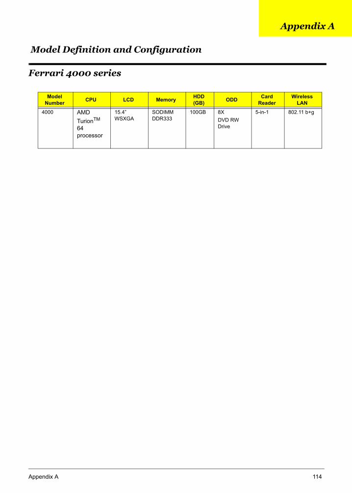
Appendix A 114
Ferrari 4000 series
Model Number CPU LCD Memory HDD
(GB) ODD Card Reader
Wireless LAN
4000 AMD TurionTM 64 processor
15.4” WSXGA
SODIMM DDR333
100GB 8X DVD RW Drive
5-in-1 802.11 b+g
Model Definition and Configuration
Appendix A

Test Compatible Components
Appendix B
This computer’s compatibility is tested and verified by Acer’s internal testing department. All of its system functions are tested under Windows® XP Home environment.
Refer to the following lists for components, adapter cards, and peripherals which have passed these tests.
Regarding configuration, combination and test procedures, please refer to the Ferrari 4000
Compatibility Test Report released by the Acer Mobile System Testing Department.
Appendix B 115
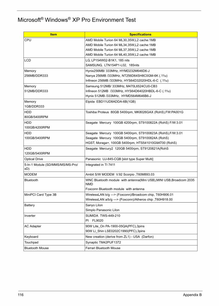
Microsoft® Windows® XP Pro Environment Test
Item Specifications
CPU AMD Mobile Turion 64 ML30,35W,L2 cache:1MBAMD Mobile Turion 64 ML34,35W,L2 cache:1MBAMD Mobile Turion 64 ML37,35W,L2 cache:1MBAMD Mobile Turion 64 ML40,35W,L2 cache:1MB
LCD LG, LP154W02-B1K1, 185 nitsSAMSUNG, LTN154P1-L02, 185nits
Memory 256MB/DDR333
Hynix256MB/ 333MHz, HYMD232M646D6-JNanya 256MB /333MHz, NT256D64SH8C0GM-6K (.11u)Infineon 256MB /333MHz, HYS64D32020HDL-6-C (.11u)
Memory512MB/DDR333
Samsung 512MB/ 333MHz, M470L6524CU0-CB3Infineon 512MB /333MHz, HYS64D64020HBDL-6-C (.11u)Hynix 512MB /333MHz, HYMD564M646B6-J
Memory1GB/DDR333
Elpida EBD11UD8ADDA-6B(1GB)
HDD80GB/5400RPM
Toshiba Proteus 80GB 5400rpm, MK8026GAX (RohS),FW:PA001G
HDD100GB/4200RPM
Seagate Mercury 100GB 4200rpm, ST9100822A (RohS) F/W:3.01
HDD100GB/5400RPM
Seagate Mercury 100GB 5400rpm, ST9100823A (RohS),F/W:3.01Seagate Mercury 100GB 5400rpm, ST9100824A (RohS)HGST, Moraga+, 100GB 5400rpm, HTS541010G9AT00 (RohS)
HDD120GB/5400RPM
Seagate Mercury2 120GB 5400rpm, ST9120821A(RohS
Optical Drive Panasonic UJ-845-CQB [slot type Super Multi]
5-In-1 Module (SD/MMS/MS/MS-Pro/xD)
Integrated in TI 7411
MODEM Ambit S/W MODEM V.92 Scorpio ,T60M893.03
Bluetooth WNC Bluetooth module with antenna(Mini USB),MINI USB,Broadcom 2035 NMDFoxconn Bluetooth module with antenna
MiniPCI Card Type 3B WirelessLAN b/g ---> (Foxconn)/Broadcom chip, T60H906.01WirelessLAN a/b/g ---> (Foxconn)/Atheros chip ,T60H918.00
Battery Sanyo LiIon Simplo Panasonic LiIon
Inverter SUMIDA TWS-449-210PI FL9020
AC Adapter 90W Lite_On PA-1900-05QA(PFC),3pins90W Li_Shin LSE0202C1990(PFC),3pins
Keyboard New creation (derive from ZL1) - USA (Darfon)
Touchpad Synaptic TM42PUF1372
Bluetooth Mouse Ferrari Bluetooth Mouse
116 Appendix B
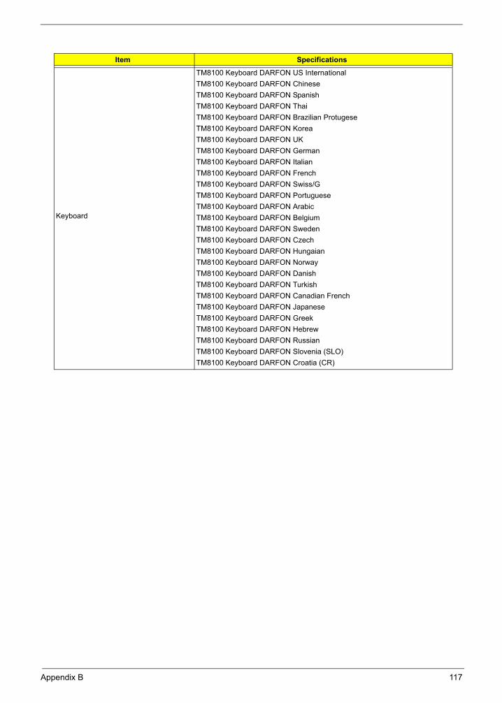
Keyboard
TM8100 Keyboard DARFON US InternationalTM8100 Keyboard DARFON ChineseTM8100 Keyboard DARFON SpanishTM8100 Keyboard DARFON ThaiTM8100 Keyboard DARFON Brazilian ProtugeseTM8100 Keyboard DARFON KoreaTM8100 Keyboard DARFON UKTM8100 Keyboard DARFON GermanTM8100 Keyboard DARFON ItalianTM8100 Keyboard DARFON FrenchTM8100 Keyboard DARFON Swiss/GTM8100 Keyboard DARFON PortugueseTM8100 Keyboard DARFON ArabicTM8100 Keyboard DARFON BelgiumTM8100 Keyboard DARFON SwedenTM8100 Keyboard DARFON CzechTM8100 Keyboard DARFON HungaianTM8100 Keyboard DARFON NorwayTM8100 Keyboard DARFON DanishTM8100 Keyboard DARFON TurkishTM8100 Keyboard DARFON Canadian FrenchTM8100 Keyboard DARFON JapaneseTM8100 Keyboard DARFON GreekTM8100 Keyboard DARFON HebrewTM8100 Keyboard DARFON RussianTM8100 Keyboard DARFON Slovenia (SLO)TM8100 Keyboard DARFON Croatia (CR)
Item Specifications
Appendix B 117
Online Support Information
Appendix C
This section describes online technical support services available to help you repair your Acer Systems.
If you are a distributor, dealer, ASP or TPM, please refer your technical queries to your local Acer branch office. Acer Branch Offices and Regional Business Units may access our website. However some information sources will require a user i.d. and password. These can be obtained directly from Acer CSD Taiwan.
Acer's Website offers you convenient and valuable support resources whenever you need them.
In the Technical Information section you can download information on all of Acer's Notebook, Desktop and Server models including:
Service guides for all models
User's manuals
Training materials
Bios updates
Software utilities
Spare parts lists
TABs (Technical Announcement Bulletin)
For these purposes, we have included an Acrobat File to facilitate the problem-free downloading of our technical material.
Also contained on this website are:
Detailed information on Acer's International Traveler's Warranty (ITW)
Returned material authorization procedures
An overview of all the support services we offer, accompanied by a list of telephone, fax and email contacts for all your technical queries.
We are always looking for ways to optimize and improve our services, so if you have any suggestions or comments, please do not hesitate to communicate these to us.
Appendix C 118