Embed Size (px)
Citation preview
a
SERVIC EMAN UALTechnical Instructionsand Set-Up Procedures
EXPEDITER ROYALE'Model A347-2
BELL-HO WELLPhillipsburg Division
TP S0035
Sell & Howell and WI-11E81 am trademarks of Sun al Mowed Comoanv .
REVISION A


EXPEDITER ROYALE INSTRUCTION AND SET-UP MANUAL REVISIONA
GENERAL INFORMATIO N
GENERAL DESCRIPTIO N
The Expediter Royale consists of the following differences a scompared to the Imperial machine :
1.
Envelope shuttle feed (as opposed to hopper feed )
2.
Electronic D .C . valves (as opposed to mechanical slid evalves or A .C . electronic valves )
3.
Optical limit switches for electronic valve actuatio n
As with the Imperial machine, the Expediter Royale may be optionall ysupplied with the indexing turnover, the vertical stacker or th econveyor delivery .
All Expediter Royales will be equipped with air and detection :controls .
ENVELOPE SHUTTLE FEED OPERATION
With the present envelope hopper and feed, the bottom envelope in 'the stack is pulled down from ledges to the raceway level and then ,pushed into the jaws of the chain gripper with a "kicker" . In theshuttle feed, the bottom of the stack is at raceway level to begi nwith and the bottom envelope is conveyed directly from the bottom o fthe stack into the gripper jaw .
Separation of the bottom envelope from the envelope stack i sachieved by pulling the back, left-hand corner (flap side) of th eenvelope off a narrow, short ledge by means of a sucker cup . When th ebottom envelope has been pulled off this ledge, and the back lef tcorner is underneath this ledge, the envelope is now free to move t othe left, out of the hopper, because now, the envelope is also clea rof the back, left-hand guide in the hopper .
The (vacuum header) suction groove and saw-toothed frictiona lelements (transfer pushers) on the shuttle plate grip the botto menvelope and provide the traction between the envelope and the shuttl eplate for transporting the envelope into the gripper jaw when th eshuttle plate moves to the left from beneath the hopper .
At the left-hand end of the vacuum header is located a "gat e " . Thisgate is made of a pliable piece of spring steel loaded in the "up "position . This gate limits the leakage of vacuum from the end of th eheader . When the vacuum comes on and pulls the envelope down into th egroove, the envelope depresses the gate downward with it . Hence, n omatter how far the envelope depresses into the groove, the gate stay sin contact with the envelope and assures that only a small vacuu mleakage occurs through the end of the groove .
I-1
EXPEDITER ROYALE INSTRUCTION AND SET-UP MANUAL REVISIONA
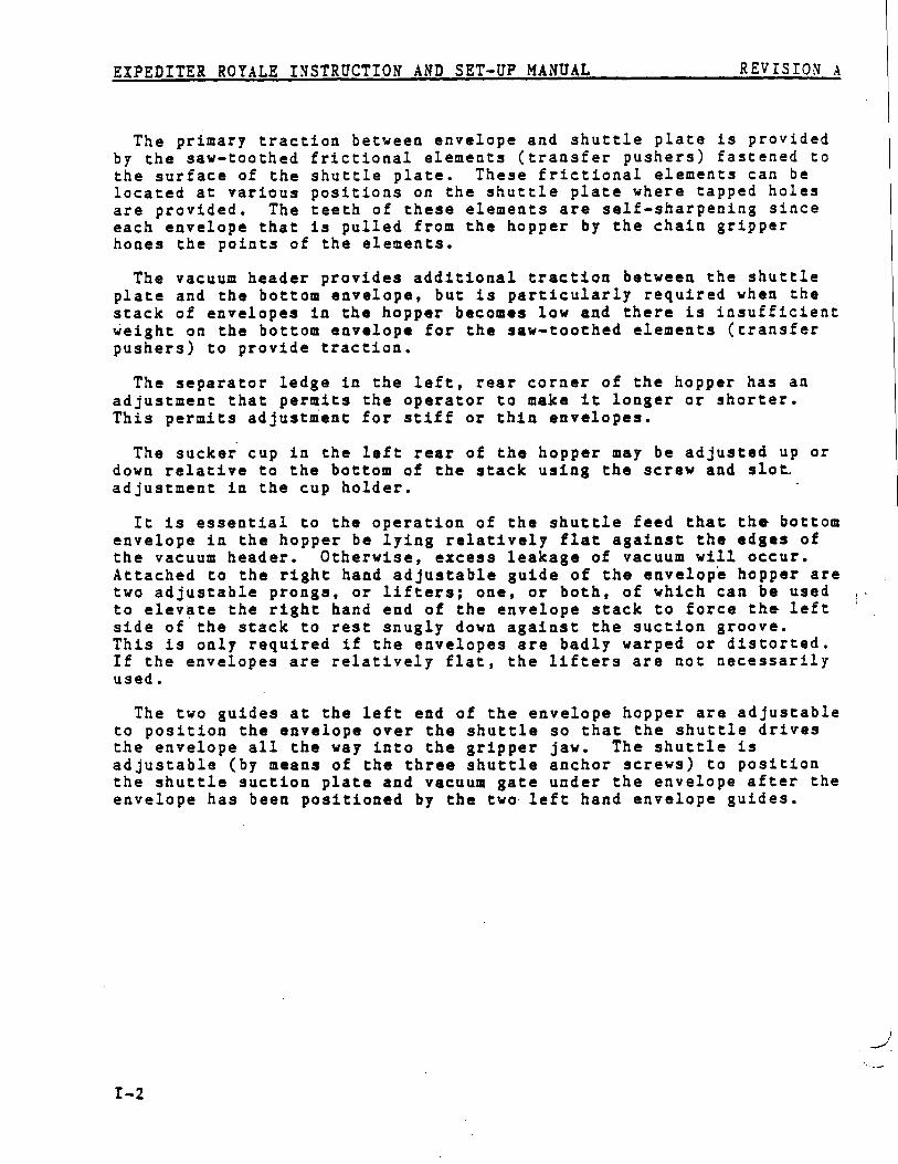
The primary traction between envelope and shuttle plate is provide dby the saw-toothed frictional elements (transfer pushers) fastened t othe surface of the shuttle plate . These frictional elements can b elocated at various positions on the shuttle plate where tapped hole sare provided . The teeth of these elements are self-sharpening sinc eeach envelope that is pulled from the hopper by the chain grippe rhones the points of the elements .
The vacuum header provides additional traction between the shuttl eplate and the bottom envelope, but is particularly required when th estack of envelopes in the hopper becomes low and there is insufficien tweight on the bottom envelope for the saw-toothed elements (transfe rpushers) to provide traction .
The separator ledge in the left, rear corner of the hopper has a nadjustment that permits the operator to make it longer or shorter .This permits adjustment for stiff or thin envelopes .
The sucker cup in the left rear of the hopper may be adjusted up o rdown relative to the bottom of the stack using the screw and slot _adjustment in the cup holder .
It is essential to the operation of the shuttle feed that th e. bottomenvelope in the hopper be lying relatively flat against the edges o fthe vacuum header . Otherwise, excess leakage of vacuum will occur .Attached to the right hand adjustable guide of the envelope hopper ar etwo adjustable prongs, or lifters ; one, or both, of which can be use dto elevate the right hand end of the envelope stack to force the lef tside of the stack to rest snugly down against the suction groove .This is only required if the envelopes are badly warped or distorted .If the envelopes are relatively flat, the lifters are not necessaril yused .
The two guides at the left end of the envelope hopper are adjustabl eto position the envelope over the shuttle so that the shuttle drive sthe envelope all the way into the gripper jaw . The shuttle i sadjustable (by means of the three shuttle anchor screws) to positio nthe shuttle suction plate and vacuum gate under the envelope after th eenvelope has been positioned by the two left hand envelope guides .
EXPEDITER ROYALE INSTRUCTION AND SET-UP MANUAL REVISIONA
TABLE OF CONTENTS
SECTION I - GENERAL INFORMATION I- 1
General Descriptio nEnvelope Shuttle Feed Operatio nProcedure For Resetting The Throwout Clutc hVacuum System Descriptio n
SECTION II - OPTICAL LIMIT SWITCHES II- 1
LED And Phototransistor Type - Style "A" Descriptio nPhoto Interrupter Type - Style "B" Descriptio nTiming The Optical Limit Switch Assemblie s
SECTION III - ROYALE SET-UP PROCEDURES
TIT- 1
Envelope Hopper Set-up
SECTION IV - SHUTTLE FEED HOPPER TROUBLESHOOTING GUIDE IV- 1
MisfeedingEnvelope Positioning Into Envelope Ja wShuttle Plate Positioning And Trave lDouble Envelope Feedin gSeparator Cup Wear And Timin gOptical Limit Switche sElectrical Problems
ii

/////////////////// // THIS PAGE INTENTIONALLY LEFT BLANK // / / / / / / / / / / / / / / / / / / /

EXPEDITER ROYALE INSTRUCTION AND SET-UP MANUAL REVISIONA
PROCEDURE FOR RESETTING THE THROWOUT CLUTC H
The normal procedure for resetting the throwout clutch on high speedmachines after a jam is as follows :
1. Clear the jam .
2. Check to see that the right hand and center jaw openers are dow n(low cam position) .
3. Check to see that the stroke stop plunger is out of the way o fthe stroke stop latch .
4. Place a wrench on the envelope chain cross shaft and turn in th eproper direction until the clutch re-engages .
The procedure fo r . resetting the clutch on the Royale model entail sthe above steps AND INCLUDES ONE MORE STEP :
Besides checking to see that the right hand and center jaw opener sare down and the stroke stop plunger is out of the way of the strok estop latch, you must also check to see that the envelope feed hoppe rshuttle is not in the full forward position (all the way to the left) .If it is, it will not allow the envelope chain to pass . If you se ethis condition after a jam, be sure to pull the machine drive bel tcounterclockwise until the shuttle moves back out of the way, and the nreset the clutch .
To prevent any unnecessary machine damage, it is very important t otrain your customers in this new procedure .
VACUUM SYSTEM DESCRIPTIO N
A different vacuum system has been incorporated into the ExpediterRoyale .
On this machine, the vacuum slide valves have been replaced with lon glife direct current solenoid valves and the vacuum piping has bee nchanged . An optical limit switch, similar in operation to the optica llimit switch used on the bank statement machines, is used to contro lthe "on-off " operation of the solenoid valves .
Solenoid valves are used at the following locations on the machine :
1. One solenoid valve for each insert hopper .
2. One solenoid valve for the corner sucker cup for envelop eshuttle .
3. One solenoid valve for the vacuum flap opener .
4. One solenoid valve for both the upper and lower suckers at th einsert plate .
A rotary valve (non-electric) is used for the vacuum on the envelopeshuttle feed .
On older Royale models, the small dust filters were removed from thevacuum system and replaced by a large filter located between the vacuui.tank and the header block from which all the vacuum lines branch off
'to their respective stations . Newer model Royales, however, includ ethese small dust filters in the machine ' s vacuum system .
The manifold for all vacuum functions has a cap plug at each en dwhich can be removed to clean it . The vacuum lines are rubber hos eor plastic tubing which can be easily removed for cleaning . Therotary valve at the shuttle feed has a removable cap on th estator(valve body) . By removing one bolt, the cap can be pulled of fexposing the vacuum groove of the rotor . The groove can then b ecleaned with a brush or air .
EXPEDITER ROYALE INSTRUCTION AND SET-UP MANUAL REVISIONA
SECTION II - OPTICAL LIMIT SWITCHE S
LED AND PHOTO TRANSISTOR TYPE - STYLE "A" DESCRIPTION II - 2
Disc Locations And Timing II - 3Mother Board Assembly II - 4Style "A" System Schematic II - 5Style "A" Power Supply Schematic II - 6
PHOTO INTERRUPTER TYPE - STYLE "B" DESCRIPTION II - 7
Disc Locations And Timing II - 7Style " B " System Schematic II - 8Style "B " Power Supply Schematic II - 9Theory Of Operation II -1 0Circuit'Description II -1 0
TIMING THE OPTICAL LIMIT SWITCH ASSEMBLIES II -1 2
EXPEDITER ROYALE INSTRUCTION AND SET-UP MANUAL
REVISIONA
OPTICAL LIMIT SWITCHES
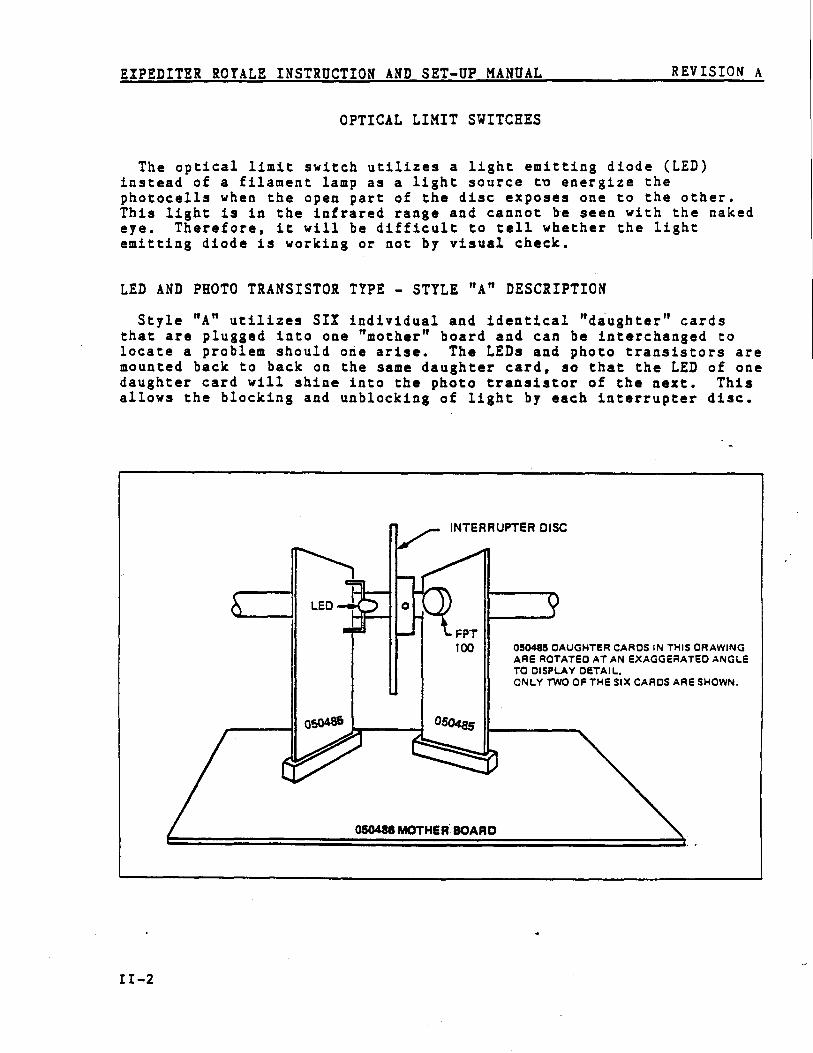
The optical limit switch utilizes a light emitting diode (LED )instead of a filament lamp as a light source to energize th ephotocells when the open part of the disc exposes one to the other .This light is in the infrared range and cannot be seen with the nake deye . Therefore, it will be difficult to tell whether the ligh temitting diode is working or not by visual check .
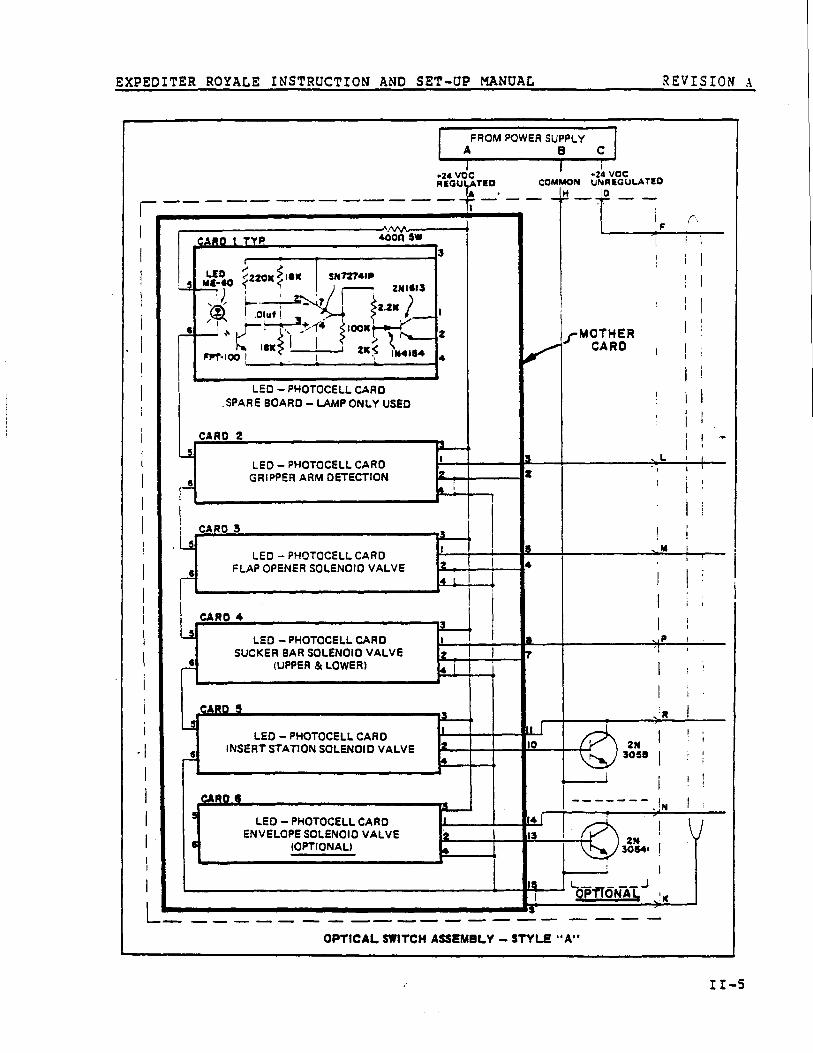
LED AND PHOTO TRANSISTOR TYPE - STYLE "A" DESCRIPTIO N
Style "A" utilizes SIX individual and identical "daughter " card sthat are plugged into one "mother" board and can be interchanged t olocate a problem should one arise . The LEDs and photo transistors ar emounted back to back on the same daughter card, so that the LED of on edaughter card will shine into the photo transistor of the next . Thi sallows the blocking and unblocking of light by each interrupter disc .
INTERRUPTER DISC
LED Y050485 DAUGHTER CARDS IN THIS DRAWIN GARE ROTATED AT AN EXAGGERATED ANGL ETO DISPLAY DETAIL .ONLY TWO OR THE SIX CARDS ARE SHOWN .
050486 MOTHER BOAR D
FPT100
EXPEDITER ROYALE INSTRUCTION AND SET-UP MANUAL
REVISION A
Q
Is
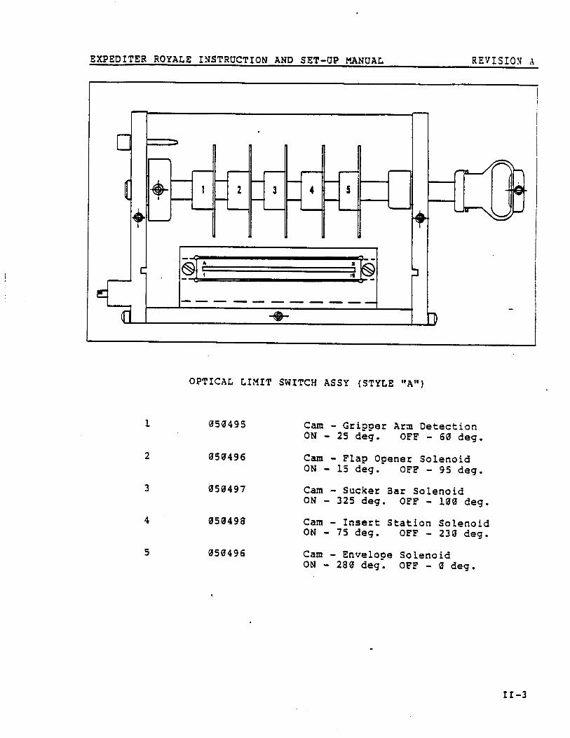
OPTICAL LIMIT SWITCH ASSY (STYLE "A" )
1 050495
Cam - Grippe rON - 25 deg .
ArmOFF
Detectio n- 60 deg .
2 050496
Cam - Fla pON - 15 deg .
Opene rOFF
Solenoi d- 95 deg .
3 050497
Cam - Sucker Bar Solenoi dON - 325 deg . OFF - 100 deg .
4 050498
Cam - Insert Station Solenoi dON - 75 deg . OFF - 230 deg .
5 050496
Cam - EnvelopeON - 280 deg . OFF
Solenoi d- 0 deg .
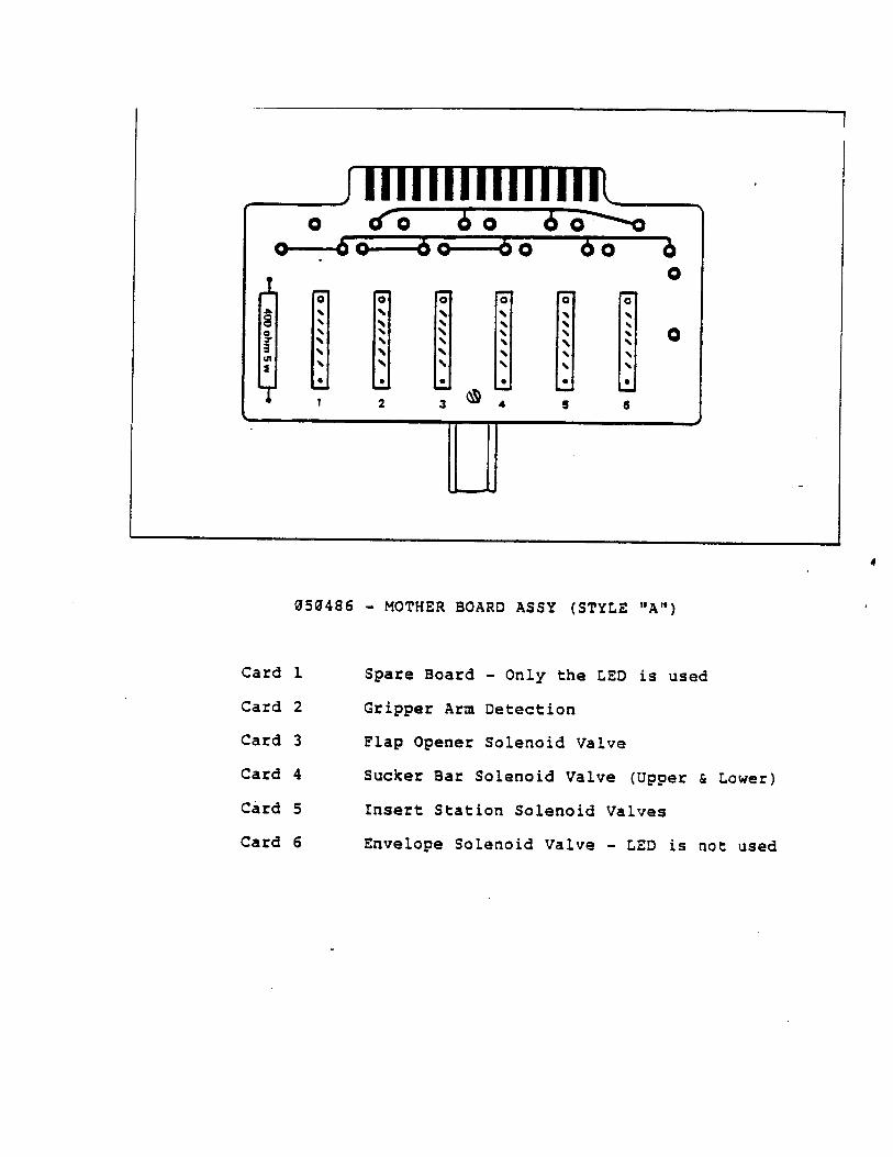
050486 - MOTHER BOARD ASSY (STYLE "A" )
Card 1
Spare Board - Only the LED is use d
Card 2
Gripper Arm Detection
Card 3
Flap Opener Solenoid Valv e
Card 4
Sucker Bar Solenoid Valve (Upper & Lower )
Card 5
Insert Station Solenoid Valve s
Card 6
Envelope Solenoid Valve - LED is not use d
O
O
O
Oo-bo-- 6o--6 o 6o
0
2
3
4
s
6
4
EXPEDITER ROYALE INSTRUCTION AND SET-UP MANUAL
REVISIONa
FROM POWER SUPPL YA
B
C
fl
t
T
ED{220K { IsK
', 1
.
.Olaf I
141q i
.2A VO CREGU ATED
—_ _. '' _.
.24 VOCCOMMON UNREGULATED
H
1 0
MOTHERCAR O
CARO t TYP,
FP-IOOI
400D5W
SN72T41P2NI$13
2.2K
"5 I N418 4L
2
I
LED — PHOTOCELL CAR D.SPARE BOARD — LAMP ONLY USE D
CARD 2
LED — PHOTOCELL CAR DGRIPPER ARM DETECTIO N
CARD 3
LED — PHOTOCELL CAR OFLAP OPENER SOLENOID VALV E
CARD 4
LED — PHOTOCELL CAR DSUCKER BAR SOLENOID VALV E
(UPPER & LOWER )
CARD5
2
I4l
5
LED — PHOTOCELL CAR OINSERT STATION SOLENOID VALV E
LED — PHOTOCELL CAR OENVELOPE SOLENOID VALV E
(OPTIONAL)
2
4
2 13
PfiTONA
OPTICAL SWITCH ASSEMBLY - STYLE "A"
11- 5
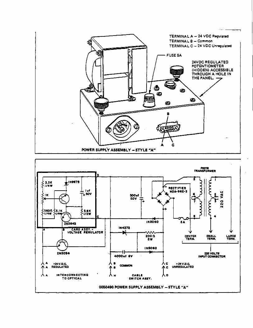
POWER SUPPLY ASSEMBLY — STYLE "A"
TERMINAL A — 24 VOC RegulatedTERMINAL 8 — Commo nTERMINAL C — 24 VDC Unregulated
24VOC REGULATE DPOTENTIOMETE R(HIDDEN) ACCESSIBL ETHROUGH A HOLE I NTHE PANEL.
A REGULATE D
A A
INTERCONNECTIN G
A
+24 V .D.C.
SWITCH ASUY .
A sCoMeaNs
CASLE TO OPTICAL
H
D
A C
+24V .D.C.C UNREGULATED
Pe77*TRANSPORMER
3.3g 1N9GT 8I/4W
.1.iK +
ssoq S .IK S .{ KI/4w
I I/2W
2143E43
8
CARO AS3Y.VOLTAGE REGULATO R
2143084
0050490 POWER SUPPLY ASSEMBLY — STYLE "A"
4000v1 8V
IN50G0N
• 220 VOLTSINPUT CONNECTOR
EXPEDITER ROYALE INSTRUCTION AND SET-UP MANUAL
REVISION A
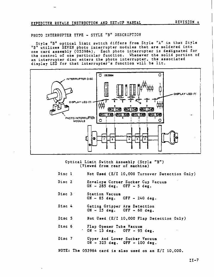
PHOTO INTERRUPTER TYPE - STYLE "B " DESCRIPTIO N
Style "B " optical limit switch differs from Style " A " in that Styl e
" B " utilizes SEVEN photo interrupter modules that are soldered int o
one card assembly (053984) . Each photo interrupter is designated fo r
the control of one particular function . Whenever the solid portion o f
an interrupter disc enters the photo interrupter, the associate d
display LED for that interrupter ' s function will be lit .
f•
oI$C 18
00 053984
INTERRUPTER DISC
7
DISPLAY LED 17 1
4.
..
C:HI!4C
S
•
2
1 IIIIIfTTTTT
;mimePHOTO INTERRUPTE R
MODULE
r-1 II II 43
1
0
SC
Optical Limit Switch Assembly (Style " B " )(Viewed from rear of machine )
Disc 1
Not Used (E/I 10,000 Turnover Detection Only )
Disc 2
Envelope Corner Sucker Cup VacuumON - 285 deg . OFF - 5 deg .
Disc 3
Station VacuumON — 85 deg .
OFF — 240 deg .
Disc 4
Gating Gripper Arm Detectio nON - 25 deg .
OFF - 60 deg .
Disc 5
Not Used (E/I 10,000 Flap Detection Only )
Disc 6
Flap Opener Tube Vacuu mON — 15 deg .
OFF — 95 deg .
Disc 7
Upper And Lower Sucker Vacuu mON - 325 deg . OFF - 100 deg .
NOTE : The 053984 card is'also used on an E/I 10,000 .
II-7
EXPEDITER ROYALE INSTRUCTION AND SET-UP MANUAL
REVISION A
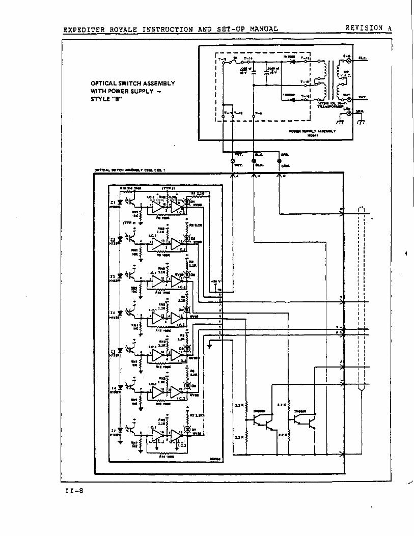
4
OPTICAL SWITCH ASSEMBLY
WITH POWER SUPPLY —
STYLE "B"
O/TICA OIICN .13O1ULY U. Olt r®••n
►
kx
AA A M
ISIS ot
tome
TT r0
1I
I
111000 T—NI4 ° 1.-
I
IQ
-Ilo-1s
T-O 0I I
X00 3urKr AS Ilar213241
rT—q
T—It —
. — TMOOS r..,f!
INT.0 (
O43 IO
cool.
Ir
N.
( *I
__ IIli1»r
33*1 .2.1
I • 11V0
RIOIOC
I .C.3
NO MN
MM3
1 .0 1 3.3*
NS2 .3R
M3 L33
MN 100N
M1 13 .3*
1.0.170 1 0
0 t II.C.2
L2 R
2.2 R
L2 IC
3.2 R
V
430 V
to
23
NO S
II-8
EXPEDITER ROYALE INSTRUCTION AND SET-UP MANUAL
REVISION A
BLK .
WHT .
053941
WHT .
BLK
1GRN .
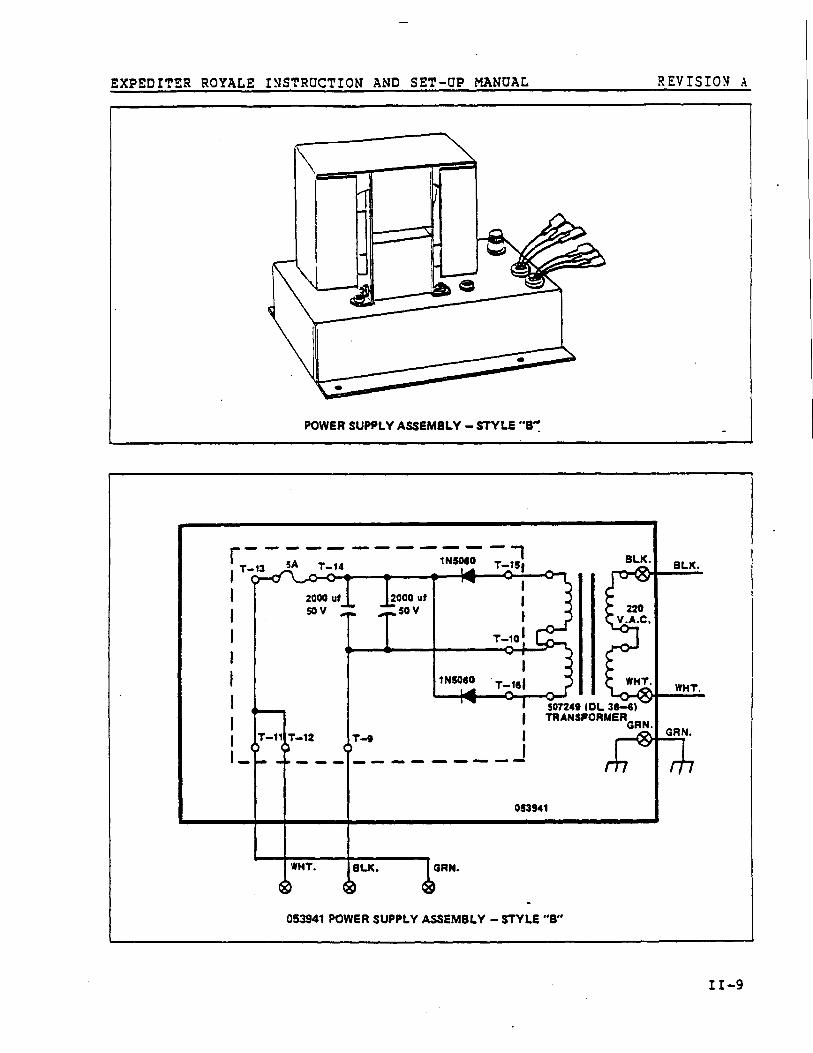
053941 POWER SUPPLY ASSEMBLY - STYLE "B "
0
11-9
EXPEDITER ROYALE INSTRUCTION AND SET-UP MANUAL
REVISION A
Optical Limit Switches (Style "B" )
Theory Of Operatio n
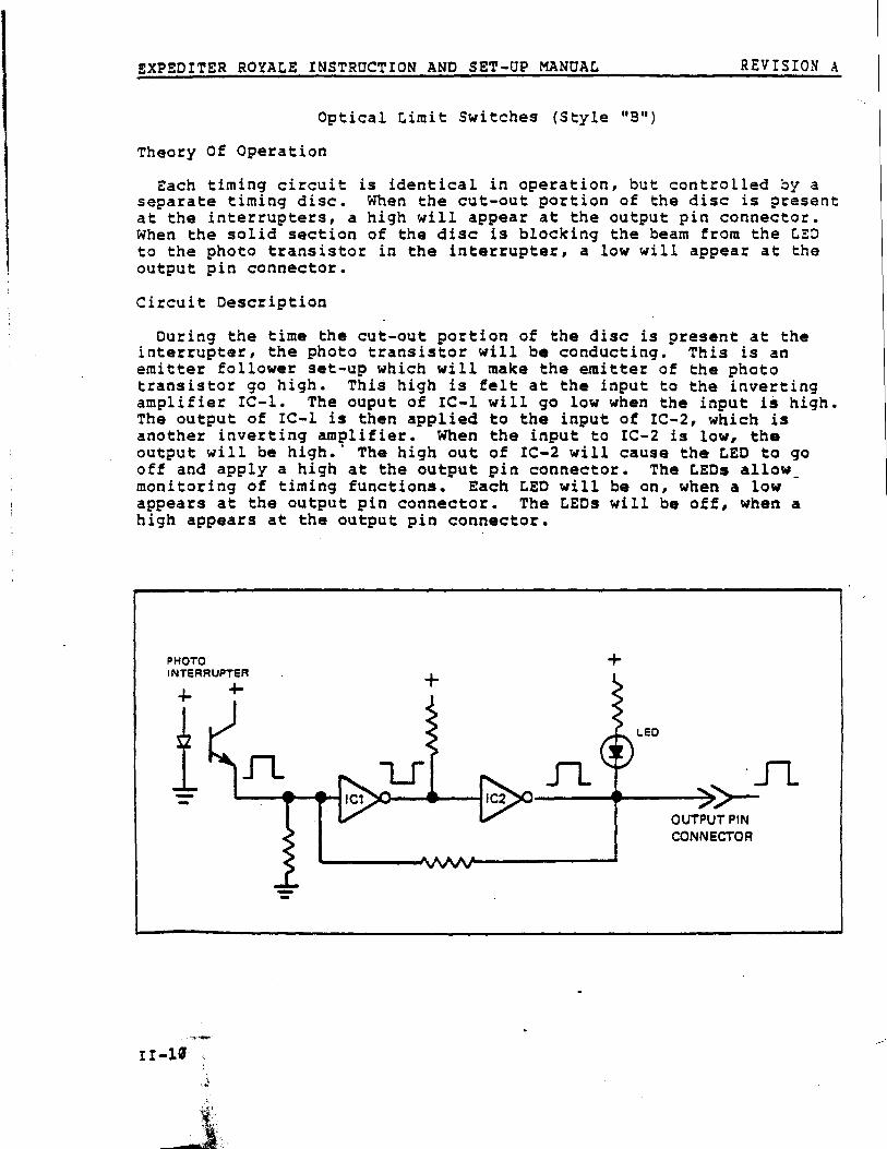
Each timing circuit is identical in operation, but controlled by aseparate timing disc . When the cut-out portion of the disc is presen tat the interrupters, a high will appear at the output pin connector .When the solid section of the disc is blocking the beam from the LE Dto the photo transistor in the interrupter, a low will appear at theoutput pin connector .
Circuit Descriptio n
During the time the cut-out portion of the disc is present at th einterrupter, the photo transistor will be conducting . This is anemitter follower set-up which will make the emitter of the phot otransistor go high . This high is felt at the input to the invertingamplifier IC-1 . The ouput of IC-1 will go low when the input is high .The output of IC-1 is then applied to the input of IC-2, which i sanother inverting amplifier . When the input to IC-2 is low, th eoutput will be high . ' The high out of IC-2 will cause the LED to gooff and apply a high at the output pin connector . The LEDs allow_monitoring of timing functions . Each LED will be on, when a lo wappears at the output pin connector . The LEDs will be off, when ahigh appears at the output pin connector .
PHOTOINTERRUPTER
LED
IC2
. J7.>>-
OUTPUT PINCONNECTOR
EXPEDITER ROYALE INSTRUCTION AND SET-UP MANUAL REVISIONA
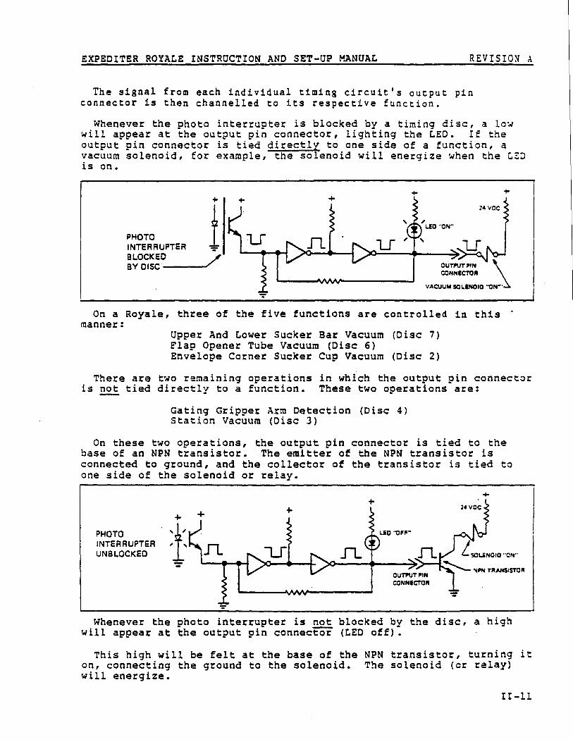
The signal from each individual timing circuit's output pi nconnector is then channelled to its respective function .
Whenever the photo interrup ter is blocked by a timing disc, a lo wwill appear at the output pin connector, lighting the LED . If theoutput pin connector is tied directly to one side of a function, avacuum solenoid, for example, the solenoid will energize when the LE Ois on .
On a Royale, three of the five functions are controlled in thi smanner :
Upper And Lower Sucker Bar Vacuum (Disc 7 )Flap Opener Tube Vacuum (Disc 6 )Envelope Corner Sucker Cup Vacuum (Disc 2 )
There are two remaining operations in which the output pin connecto ris not tied directly to a function . These two operations are :
Gating Gripper Arm Detection (Disc 4 )Station Vacuum (Disc 3 )
On these two operations, the output pin connector is tied to th ebase of an NPN transistor . The emitter of the NPN transistor i sconnected to ground, and the collector of the transistor is tied t oone side of the solenoid or relay .
PHOT OINTERRUPTE RUNBLOCKED
Whenever the photo interrupter is not blocked by the disc, a hig hwill appear at the output pin connector (LED off) .
This high will be felt at the base of the NPN transistor, turning i ton, connecting the ground to the solenoid . The solenoid (or relay )will energize .
EXPEDITER ROYALE INSTRUCTION AND SET-UP MANUAL
REVISION A
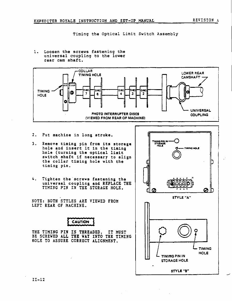
Timing the Optical Limit Switch Assembl y
1 . Loosen the screws fastening th euniversal coupling to the lowe rrear cam shaft .
2. Put machine in long stroke .
3. Remove timing pin from its storag ehole and insert it in the timinghole (turning the optical limi tswitch shaft if necessary to alig nthe collar timing hole with th etiming pin .
4. Tighten the screws fastening th euniversal coupling and REPLACE TH ETIMING PIN IN THE STORAGE HOLE .
NOTE : BOTH STYLES ARE VIEWED FROMLEFT REAR OF MACHINE .
THE TIMING FIN IS THREADED . IT MUSTBE SCREWED ALL THE WAY INTO THE TIMINGHOLE TO ASSURE CORRECT ALIGNMENT .
COLLA RTIMING HOLE
PHOTO INTERRUPTER DISC S(VIEWED FROM REAR OF MACHINE)
TIMINGHOLE
oIsc oIs c6
oiscolsc4
STYLE "A"
TIMING PIN I NSTORAGE HOL E
STYLE "S"
TIMINGHOLE
EXPEDITER ROYALE INSTRUCTION AND SET-UP MANUAL REVISIONA
SECTION III - ROYALE SET-UP PROCEDURE S
ENVELOPE HOPPER SET-UP III - 2
Front Rail And Right Hand Side Guide Adjustments III - 2Envelope Separator Ledge Adjustment III - 4Throat Knife Adjustment III - 5Envelope Positioning Into Envelope Jaw III - 6Envelope Lifters Adjustment III - bShuttle Plate Adjustment III - 8F ront Table Positioning III -1 0Loading The Envelope Hopper III -10

EXPEDITER ROYALE INSTRUCTION AND SET-UP MANUAL REVISIONA
SECTION III - A347-2 ROYALE SET-UP PROCEDUR E
This section of the manual deals only with the initial set-up an dfunctional adjustments needed for efficient operation of the envelop eshuttle feed . All left or right hand directions following are based o nthe operator facing the front of the machine . Adjustments are made i nthe order given to minimize making them a second time . Atroubleshooting guide follows this section . Use these sections i nconjunction with the Basic Timing Manual, TP50025 .
ENVELOPE HOPPER SET-UP
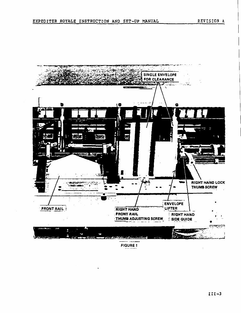
Figure 1
Basically, the Envelope Hopper has only two adjustments . Theseadjustments are normally the only ones required to run envelopes fro mthe Shuttle Hopper . Specialized adjustments are explained later i nthis manual .
O FRONT RAIL adjustment . Move in or out for envelope depth .
0
01
RIGHT HAND SIDE GUIDE . Move left or right for envelop ewidth .
3 Attached to the Right Hand Side Guide are two ENVELOP ELIFTERS . These are locked in the " out " position for mostenvelopes .
Front Rail And Right Hand Side Guide Adjustment s
O Loosen the two Envelope Hopper/FRONT RAIL THUMB ADJUSTIN GSCREWS and the Envelope Hopper Side Guide RIGHT HAND LOC KTHUMB SCREWS .
Place one envelope in the hopper making sure that the lef tcorner of the top of the envelope rests on the Separato rLedge next to the Separator Cup . (Refer to Figure 2 . )
O Place a stack of envelopes on top of the first envelope .
O Position both the Envelope Hopper Front Rail, and th eRight Hand Side Guide against the stack of envelopes usin gone envelope as a thickness gauge to insure that th eenvelopes do not bind in the hopper . THE ENVELOPE HOPPE RSHOULD BE SNUG BUT IT SHOULD NOT BIND THE ENVELOPES . ON EENVELOPE THICKNESS CLEARANCE BETWEEN THE HOPPER AND THEENVELOPE IS RECOMMENDED .
O7
Check the left hand end of the Envelope Hopper/Front Rai lto make sure that the rail is parallel with the front o fthe machine before tightening the rail .
111-2
EXPEDITER ROYALEINSTRUCTION ANDSET-UP MANUAL REVISIONA
SINGLE ENVELOP E
CLEARANCE
`=-» x ^
RIGHT HAND LOCKTHUMB SCREW
.ENVELOPE 'HAND
; RIGHT: FRONT RAIL
RIGHT HANDTHUMB ADJUSTING SCREW
SIDE GUIDE
FRONT RAIL !
°
-
--FIGURE 1
EXPEDITERROYALEINSTRUCTION ANDSET-UP MANUAL
REVISION A
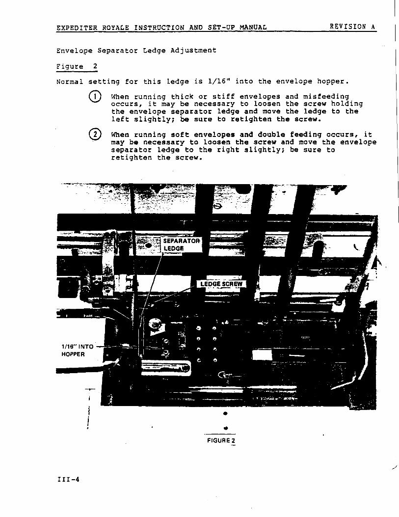
Envelope Separator Ledge Adjustmen t
Figure 2
Normal setting for this ledge is 1/16" into the envelope hopper .
When running thick or stiff envelopes and misfeedingoccurs, it may be necessary to loosen the screw holdingthe envelope separator ledge and move the ledge to th eleft slightly ; be sure to retighten the screw .
When running soft envelopes and double feeding occurs, i tmay be necessary to loosen the screw and move the envelopeseparator ledge to the right slightly ; be sure t oretighten the screw .
FIGURE 2
0
0
III-4

EXPEDITER ROYALE INSTRUCTION AND SET—UP MANUAL REVISIONA
Throat Knife Adjustmen t
Figure 3
The THROAT KNIFE is used to aid in the separation of the envelopes ;too large a clearance will allow two envelopes to feed .
(:) Jog the machine until the SUCTION GATE is directly unde rthe Throat Knife .
O Adjust the Throat Knife until it is a minimum of 1/32 "above the GATE SPRING . Vacuum will pull the botto menvelope down into the Suction Plate allowing it to clea rthe Throat Knife while the remaining envelopes are hel dback by the knife .
More clearance will be required on side seam envelopes .
FIGURE 3

EXPEDITER ROYALE INSTRUCTION AND SET—UP MANUAL
REVISION A
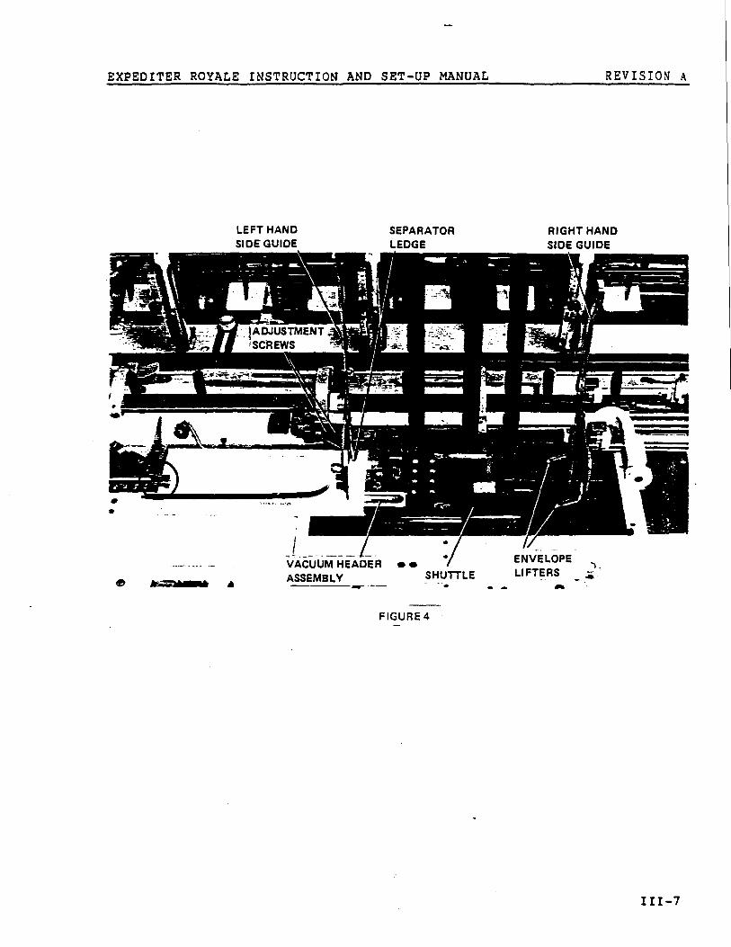
Envelope Positioning Into Envelope Ja w
Figure 4
O Positioning the envelope into the Envelope Gripper Jaw i saccomplished by moving the slotted envelope LEFT HAND SIDEGUIDES . The envelope should feed fully into the jaw .Loosen the ADJUSTMENT SCREWS and move both guides a srequired . After making any adjustments on the two Lef tHand Side Guides, both the SEPARATOR LEDGE and the RIGHTHAND SIDE GUIDE must be adjusted . At times, due t odifficult envelopes, it may be necessary to position th eenvelopes so that they do not feed fully into the jaw .
O If the Left Hand Side Guides are moved too far, it may b enecessary to reposition the SHUTTLE also . (See Shuttl eAdjustment . )
Envelope Lifters Adjustmen t
Figure 4
O In the event of badly warped envelopes, it may b enecessary to use one or two of the right hand ENVELOP ELIFTERS .
¢* Always try the standard hopper set—up first . In man ycases, you will find that the weight of a full hopper wil lkeep the bottom envelopes flat and no further adjustment sare necessary .
O To adjust the lifters for warped envelopes, remove all bu tone envelope from the hopper . The left hand edge of th eenvelope must lay flat on the Shuttle Plate VACUUM HEADE RASSEMBLY .
O Adjust either or both of the Envelope Lifters until th eleft side of the warped envelope lays flat over theShuttle Plate Vacuum Header Assembly and the inside lef tcorner of the envelope is resting on the Separator Ledge .
EXPEDITER ROYALE INSTRUCTION AND SET-UP MANUAL REVISIONA
LEFT HANDSIDE GUIDE
SEPARATO RLEDGE
RIGHT HANDSIDE GUID E
VACUUM HEADER • •ASSEMBLY
FIGURE 4 SHUTTLE
ENVELOP ELIFTERS

EXPEDITER ROYALE INSTRUCTION AND SET-UP MANUAL
REVISIONA
Shuttle Adjustmen t
If the Shuttle is adjusted too far to the left or right i twill strike the table ; always turn the machine over b yhand to check this adjustment . Damage to the VacuumHeader Assembly will occur if allowed to travel too far t othe left .
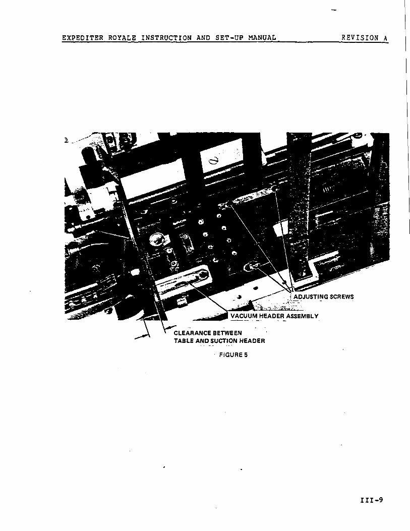
Figure 5
O The Shuttle Carriage and Anchor are held together by thre epan head ADJUSTING SCREWS . The carriage itself is slotte dat these three points and when loosened, will allow lef tor right movement of the Shuttle Carriage .
O The Shuttle Carriage should be adjusted so that the lea dedge of the envelope overhangs the front of the Vacuu mHeader Assembly by 1/32" when Shuttle is all the way t othe right .
EXPEDITER ROYALE INSTRUCTION AND SET-UP MANUAL
REVISIONA
CLEARANCE BETWEE NTABLE AND SUCTION HEADE R
FIGURE 5
EXPEDITER ROYALE INSTRUCTION AND SET-UP MANUAL REVISIONA
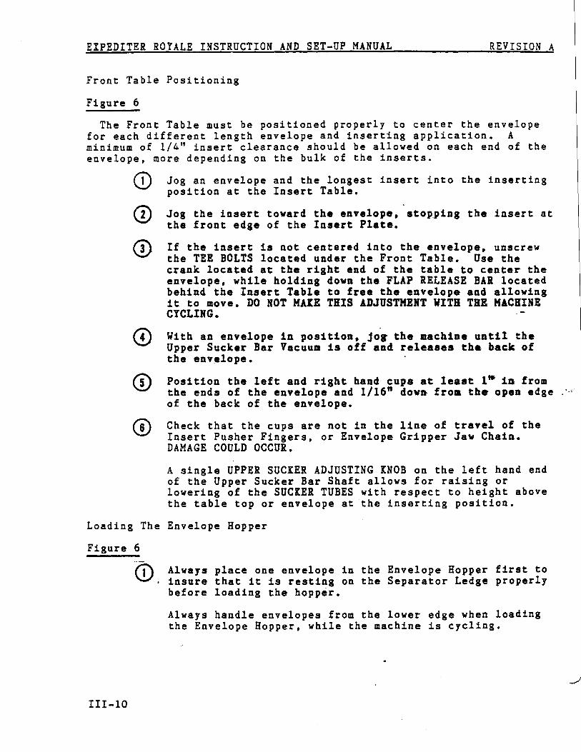
Front Table Positionin g
Figure 6
The Front Table must be positioned properly to center the envelop efor each different length envelope and inserting application . Aminimum of 1/4" insert clearance should be allowed on each end of th eenvelope, more depending on the bulk of the inserts .
O
O1
Jog an envelope and the longest insert into the insertin gposition at the Insert Table .
Jog the insert toward the envelope, stopping the insert a tthe front edge of the Insert Plate .
(
If the insert is not centered into the envelope, unscre wthe TEE BOLTS located under the Front Table . Use thecrank located at the right end of the table to center th eenvelope, while holding down the FLAP RELEASE BAR locate dbehind the Insert Table to free the envelope and allowin git to move . DO NOT MAKE THIS ADJUSTMENT WITH THE MACHIN ECYCLING .
*¢ With an envelope in position, jog the machine until th eUpper Sucker Bar Vacuum is off and releases the back o fthe envelope .
O Position the left and right. hand cups at least 1' in fro mthe ends of the envelope and 1/16" down from the open edg eof the back of the envelope .
V Check that the cups are not in the line of travel of th eInsert Pusher Fingers, or Envelope Gripper Jaw Chain .DAMAGE COULD OCCUR .
A single UPPER SUCKER ADJUSTING KNOB on the left hand en dof the Upper Sucker Bar Shaft allows for raising o rlowering of the SUCKER TUBES with respect to height abov ethe table top or envelope at the inserting position .
Loading The Envelope Hoppe r
Figure 6
O Always place one envelope in the Envelope Hopper first t oinsure that it is resting on the Separator Ledge properl ybefore loading the hopper .
Always handle envelopes from the lower edge when loadin gthe Envelope Hopper, while the machine is cycling .

EXPEDITER ROYALE INSTRUCTION AND SET-UP MANUAL
REVISION A
UPPER SUCKE RADJUSTING KNO B
•
TEE BOLTS UNDER FRONT TABL E
FIGURE 6
/////////////////// // THIS PAGE INTENTIONALLY LEFT BLANK /////////////////////
EXPEDITER ROYALE INSTRUCTION AND SET-UP MANUAL
REVISION A
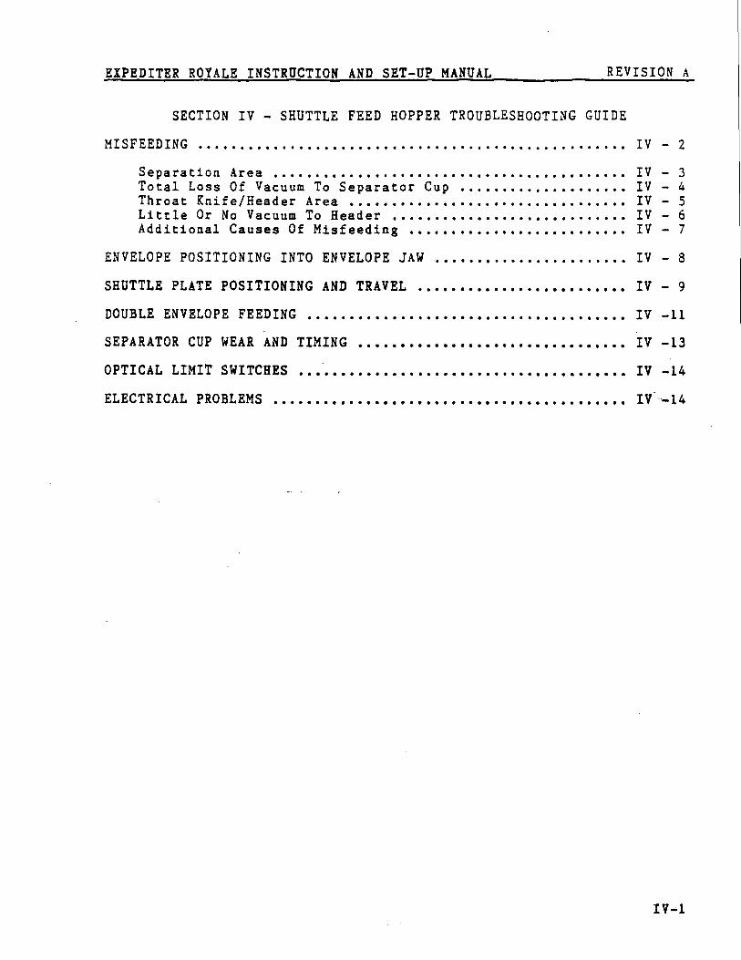
SECTION IV - SHUTTLE FEED HOPPER TROUBLESHOOTING GUIDE
MISFEEDING IV - 2
Separation Area IV - 3Total Loss Of Vacuum To Separator Cup IV - 4Throat Knife/Header Area IV - SLittle Or No Vacuum To Header IV - 6Additional Causes Of Misfeeding IV - 7
ENVELOPE POSITIONING INTO ENVELOPE JAW
IV - 8
SHUTTLE PLATE POSITIONING AND TRAVEL IV - 9
DOUBLE ENVELOPE FEEDING IV -1 1
SEPARATOR CUP WEAR AND TIMING IV -1 3
OPTICAL LIMIT SWITCHES IV -14
ELECTRICAL PROBLEMS IV=--14
IV- 1
EXPEDITER ROYALE INSTRUCTION AND SET-UP MANUAL
REVISION A
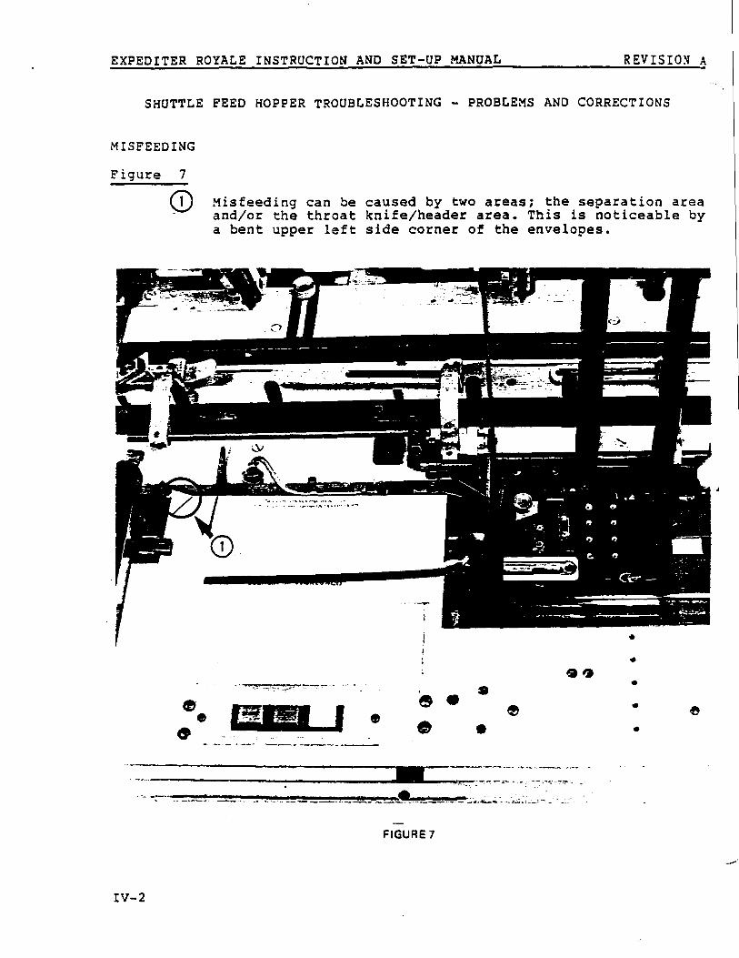
SHUTTLE FEED HOPPER TROUBLESHOOTING - PROBLEMS AND CORRECTION S
MISFEEDING
Figure
O1
Misfeeding can be caused by two areas ; the separation areaand/or the throat knife/header area . This is noticeable bya bent upper left side corner of the envelopes .
9 I)
0
r a
0• e
FIGURE 7
IV- 2
EXPEDITER ROYALE INSTRUCTION AND SET-UP MANUAL REVISIONA
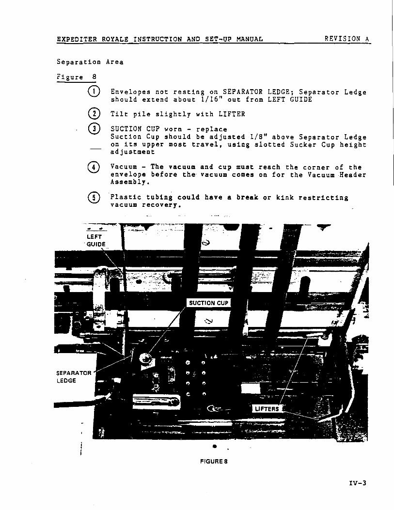
Separation Are a
Figure 8
O Envelopes not resting on SEPARATOR LEDGE ; Separator Ledg eshould extend about 1/16" out from LEFT GUID E
O2
Tilt pile slightly with LIFTER
O SUCTION CUP worn - replac eSuction Cup should be adjusted 1/8 " above Separator Ledg eon its upper most travel, using slotted Sucker Cup heigh tadjustmen t
O Vacuum - The vacuum and cup must reach the corner of th eenvelope before the vacuum comes on for the Vacuum Heade rAssembly .
O Plastic tubing could have a break or kink restrictin gvacuum recovery .
•
FIGURE 8
IV- 3
EXPEDITER ROYALE INSTRUCTION AND SET-UP MANUAL
REVISION A
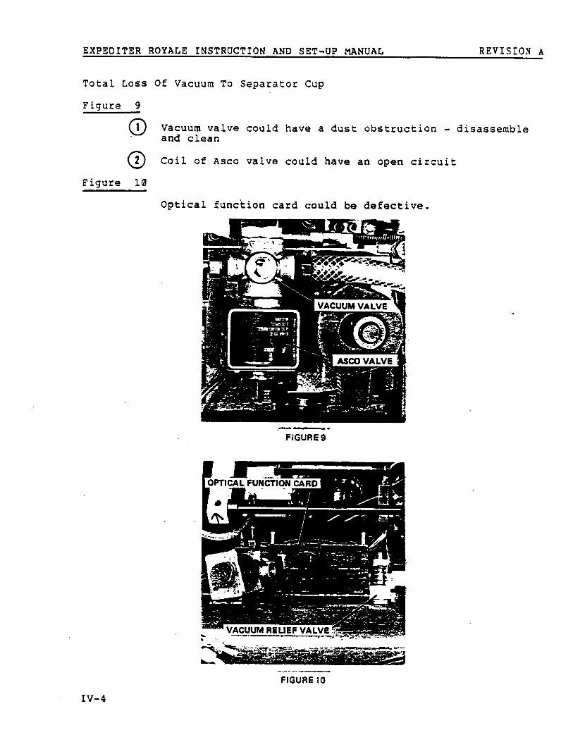
Total Loss Of Vacuum To Separator Cu p
Figure
01
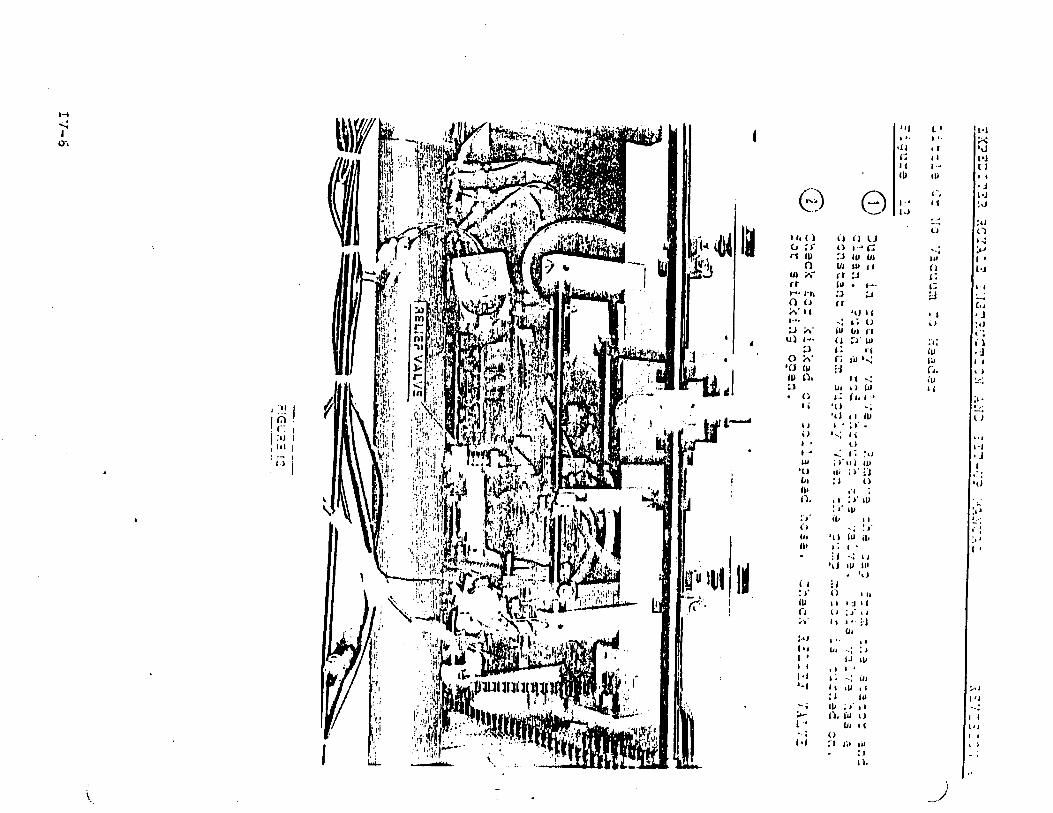
Vacuum valve could have a dust obstruction - disassembl eand clea n
02
Coil of Asco valve could have an open circui t
Figure lA
Optical function card could be defective .
FIGURE 9
FIGURE 10
IV- 4
g -Li
Ar,.S ;/, 331:
DNISCS ELYZ.' ---,,
k
41
Ee::,-:E/ ■ I :E
ED :7E CrF1
_
_ _isletPaS.TV VEOt'B
_
zueq zo pa :s ;P.; 'reczc eq .:e= EzTj.es e :sf)
CPC E‘tO 70 SSCU';CTU. ZtZC pi–CCrZ :Cr CSn= :ETPF E7o :,uci ; el; :1, pus' D1=Es z :yf_:
:Get . :eq es F
el7c ILc :7
:snm
;p Ei ;7
zzsd
:eLcz Tls
:Sc ; :Fr: u
. e :-E-D zE ;R ;H
17 'i-TLiT Z
:aT'eE/i7u):
0.(1
r) it Cl)"
t )ri (U
:.l IU Ul11I
( 1Lll i*
( r :3
C;r- •
i--•• I-it
:3
:J
f0 0n•1{
'111( t)
r1Ll
ii
l :
rf
( p0
r; u'
l:1,0 IVID
iut )
t ; I L't
;'tl
•I t
1 •
I .
1 ; "ti66 1
'O
'i
. 11
6' 11 '1 .
:
■OID
!J.tu
'II (d ( bID
. 1NJ IU (II
. 't ): lt )
ID
t
I -i I (;I' ■ )
I t
s . - J
:1
ivi
,
i ,I•I
s ;t ■ V , r
:i
1 06 i
1) . Vi oUs I t
01 I
:1 1 :, III

EXPEDITER ROYALEINSTRUCTION ANDSET-UPMANUAL REVISIONA
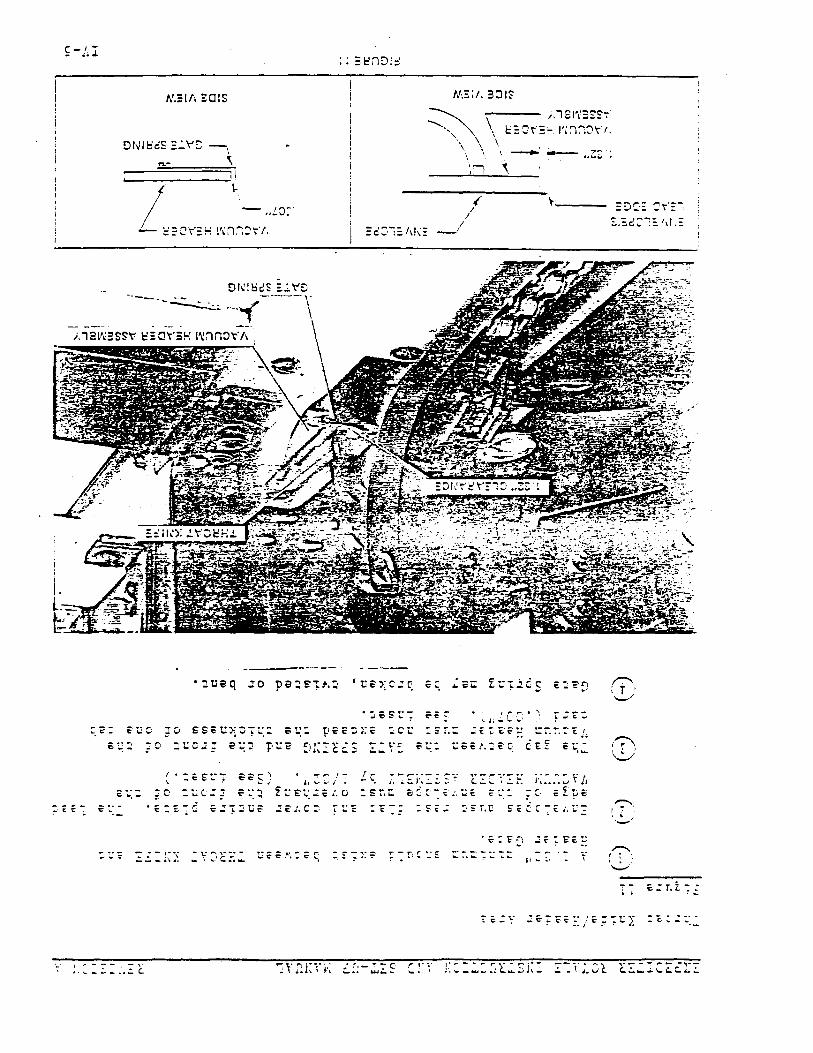
Figure 13
Hopper RIGHT HAND GUIDE set too loose causing the Shuttl ePlate to drag the envelope to the right . After the Shuttl ebrings the envelope out into the Jaw, readjust the Righ tHand Guide .
OZ
Window envelopes could be catching on rear portion o fTRANSFER PUSHERS . Remove or relocate Pushers .
O3
Window could .be catching on rear edge of VACUUM HEADE RASSEMBLY . Bevel rear edge of Header with a file .
(
The envelope may have Transfer Pusher pin marks or b epunched through the envelope . Add more Pushers todistribute the weight and this should reduce the size o fthe punch marks .
O Porous envelopes, fill the. Hopper only part way .
Envelope Gripper Jaw Chain out of adjustment .
O
VACUUM HEADERASSEMBLY
RIGHT HANDGUIDE
FIGURE 1 3
IV-7

EXPEDITER ROYALE INSTRUCTION AND SET—UP MANUAL REVISIONA
ENVELOPE POSITIONING INTO ENVELOPE JA W
Figure 1 4
`'J Move both LEFT SIDE GUIDES to the left or right th edesired amount you wish to correct . Readjust the SEPARATO RLEDGE for 1/16" exposure . Also readjust the Right Sid eGuide and Shuttle Plate to maintain 1/32" envelop eoverhang on envelope's lead edge .
O Timing of the Envelope Gripper Jaw Chain is critical ; theHEEL should be 1/32 " to 1/16" past the SPROCKET SUPPOR TPOST in long stroke .
HEEL OF ENVELOPECHAIN JAW
JAW OPENERS
SPROCKE T
.9'SUPPORT POST
1/32" to 1/16"
E
1
FIGURE 14

EXPEDITER ROYALE INSTRUCTION AND SET-UP MANUAL
REVISION A
SHUTTLE PLATE POSITIONING AND TRAVEL
Figure 1 5
U1
This is a one time adjustment and care should be exercise dto prevent damage to shuttle parts or assemblies . I fmoved too far to the right or left the plate will strik ethe front table .
LEFT HAND—1 CLEARANC E
* y A • •
SHUTTLE
RIGHT HAND -PLATE
CLEARANCE
FIGURE 1 5
EXPEDITER ROYALE INSTRUCTION AND SET-UP :`MANUAL REVISIC A
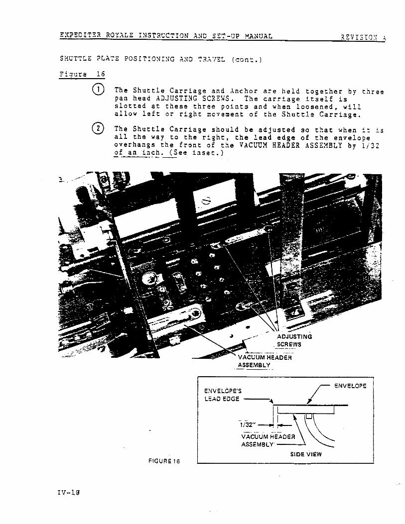
SHUTTLE PLATE POSITIONING AND TRAVEL (cont . )
inure 1 6
O1
The Shuttle Carriage and Anchor are held together by thre epan head ADJUSTING SCREWS . The carriage itself i sslotted at these three points and when loosened, wil lallow left or right movement of the Shuttle Carriage .
Q The Shuttle Carriage should be adjusted so that when it i sall the way to the right, the lead edge of the envelop eoverhangs the front of the VACUUM HEADER ASSEMBLY by 1/3 2of an inch . (See inset .)
ADJUSTIN GSCREWS
VACUUM HEADE RASSEMBLY
FIGURE 1 6
IV-1d

EXPEDITER ROYALE INSTRUCTION AND SET-UP MANUAL REVISIONA
DOUBLE ENVELOPE FEEDING
Figure 1 7
lO Envelope hopper set too loose . Proper clearance betweenfront rail and envelopes, and right side guide an denvelopes should be the thickness of one envelope .
Figure 1 8
(
Not enough separator ledge . Ledge should be exposed intohopper about 1/16" .
SINGLE ENVELOPE CLEARANC E
FIGURE 17
IV-11

a :
'- UI I , Y l l t l,l ;._ ; .J . J ll+J lu
. :1 :*• • v ( .1 (u : .' : J
1-' U Li
I . . C) :( : l•1 C) U I I)1I . IL II) ;.-
l au' r w 1+
.-I L' : (A (L I . U(D
:J 1-• fa
t_)
' UID
I- • :l
/ .; W•(
ID
t . .
4 :
1 . •1 • Cs-
1 . .
J
Cr . 1 • I .. . -17 rll G 0 rr I- , ti U
(L
_W O u a: :J' /u
•' ' IL IL • J 1 II1 IS Iu i-1 iu •
I
;, ;J
I > . . 11-1 . t: uiID lj • 'il ) 1 r J rr 1u
3
Ul rr (u (D P .a (D 1JF•• Iu 1 1
W J rr WP (D I *•
n (u
0I u
iu
W
:J0
I
I
;a J
1 1
a I .
O :1.
(II
I'• (u
(I)
' 1 I -• 1) I-+ . G;s- t11 ' sr: ;J' ;J
ID CJ' 11 01 :J
1•-114 iJ.0 ID 41 1) G :J
1 ,CI .0 N ID :J IL I r
it) (t t-: kJI- • U 1' u' Cr . 1t: I r (LU Li ' I I .. .• (D • 1'U
III
I r
t o N:, .
;I- C )
(D (0 I) •
. 1 1 u L' I ( . J 1 1 .W J
1
ID :J• I : 1 11) 1 . 1-4 1) UI IJ ID U .1 '•1 I :
U
:J
:J - t•JUQ ( U:D
.
t • .
;J' : J(. U) :J rI
t:. .
IJ 4J•
I L( U
UJ iD
v t• 1fU UI-' 17 l-+U 1 . 0) U +lJ N . I t4i) O J
0 UI W I LI. (1
1-•41 r. 1 - . . 1 - • ILrr
rt O1-' N. U )i: 0UIL :J LI
, : 1rr ' u
iU t ; 1•u rr
I L
1L t
: I U 0 . I' -Ill I I la (D
(L (I .
iu n
(0 i t
1-•
(D
:J ti
• G
I UUJ Ill
• C ) w I ur.)
I -J a 1-' : J( .I . C . IL t)I .' . •1 I( '.1
I) I ( ;J •
(,It ' Iu
U11u I) tJ cuII) rr (1) 11 r r
U)it
r- -j (ur J I II •, . .
('I C ,
I . .
: .l
I r
I-.L I( ur) .
r r()
EXPED .̂ R R0YALE INSTRUCTION AND SET-UP MANUAL
R E' i IS :0 .` t
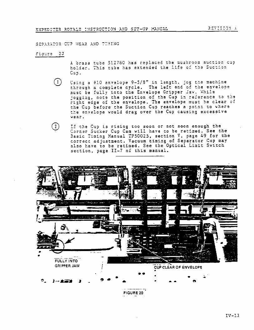
SEPARATOR CUP : ;EAR AND T ._IING
Fi g :.=e
2J
A brass tube 512750 has replaced the mushroom suction cu p
holder . This tube has extended the life of the Suctio nCup .
0
Using a 410 envelope 9-5/8 " in length, jog the machin e
through a complete cycle . The left end of the envelo p emust be fully into the Envelope Gripper Jaw . Whil e
jogging, note the p osition of the Cup in reference to th e
right edge of the envelope . The envelope must be clear o f
the Cup before the Suction Cup reaches a point to wher ethe envelope would drag over the Cup causing excessiv ewear .
If the Cup is rising too soon or not soon enough th eCorner Sucker Cu p Cam will have to be retimed . See th eBasic Timing Manual TP50025, section V, page 49 for th e
correct adjustment . Vacuum timing of Separator Cup ma yalso have to be retimed . See the Optical Limit Switc h
section, page II-7 of this manual .
'fl y )- * * e i
FIGURE 20
* •
EXPEDITER ROYALE INSTRUCTION AND SET-UP MANUAL
REVISIONA
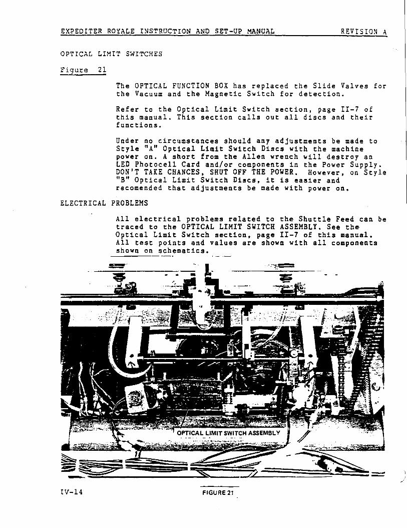
OPTICAL LIMIT SWITCHE S
Figure 21
The OPTICAL FUNCTION BOX has replaced the Slide Valves fo rthe Vacuum and the Magnetic Switch for detection .
Refer to the Optical Limit Switch section, page II-7 o fthis manual . This section calls out all discs and thei rfunctions .
Under no circumstances should any adjustments be made t oStyle " A " Optical Limit Switch Discs with the machin epower on . A short from the Allen wrench will destroy a nLED Photocell Card and/or components in the Power Supply .DON'T TAKE CHANCES, SHUT OFF THE POWER . However, on Styl e"B" Optical Limit Switch Discs, it is easier andrecomended that adjustments be made with power on .
ELECTRICAL PROBLEM S
All electrical problems related to the Shuttle Feed can b etraced to the OPTICAL LIMIT SWITCH ASSEMBLY . See theOptical Limit Switch section, page II-7 of this manual .All test points and values are shown with all component sshown on schematics .
IV-14
FIGURE 2 1