Embed Size (px)
Citation preview
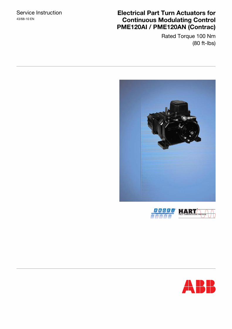
Service Instruction43/68-10 EN
Electrical Part Turn Actuators forContinuous Modulating Control
PME120AI / PME120AN (Contrac)Rated Torque 100 Nm
(80 ft-lbs)
P R O F I
B U S
PROCESS FIELD BUS
®
Electrical Part Turn Actuators for Continuous Modulating Control PME120AI / PME120AN (Contrac)
Service InstructionDocument No. 43/68-10 ENIssued: December 2005
Manufacturer:ABB Automation Products GmbHSchillerstr. 7232425 MindenGermany
Tel: +49 551 905-534Fax: +49 551 905-555
© Copyright 2005 by ABB Automation Products GmbHWe reserve the right to technical amendments
This document is protected by copyright. Information in this document is intended only to assist theuser in safe and efficient operation of the equipment. Its contents are not to be reproduced in full or partwithout prior approval of legal owner.
2 Electrical Part Turn Actuators for Continuous Modulating Control PME120AI / PME120AN (Contrac) 43/68-10 EN
Content . . . . . . . . . . . . . . . . . . . . . . . . . . . . . . . . . . . . . . . . . . . . . . . . . . . . . . . . . . . . . . . . . . . Page
Important information . . . . . . . . . . . . . . . . . . . . . . . . . . . . . . . . . . . . . . . . . . . . . . . . . . . . . . . . . . . 4General . . . . . . . . . . . . . . . . . . . . . . . . . . . . . . . . . . . . . . . . . . . . . . . . . . . . . . . . . . . . . . . . . . . . . . 4Symbols . . . . . . . . . . . . . . . . . . . . . . . . . . . . . . . . . . . . . . . . . . . . . . . . . . . . . . . . . . . . . . . . . . . . . . 4Transport and storage . . . . . . . . . . . . . . . . . . . . . . . . . . . . . . . . . . . . . . . . . . . . . . . . . . . . . . . . . . . . 4
Introduction . . . . . . . . . . . . . . . . . . . . . . . . . . . . . . . . . . . . . . . . . . . . . . . . . . . . . . . . . . . . . . . . . . . 5Safety and precautions . . . . . . . . . . . . . . . . . . . . . . . . . . . . . . . . . . . . . . . . . . . . . . . . . . . . . . . . . . . . 5Tools . . . . . . . . . . . . . . . . . . . . . . . . . . . . . . . . . . . . . . . . . . . . . . . . . . . . . . . . . . . . . . . . . . . . . . . . 5
Actuator versions. . . . . . . . . . . . . . . . . . . . . . . . . . . . . . . . . . . . . . . . . . . . . . . . . . . . . . . . . . . . . . . 6PME120 AI . . . . . . . . . . . . . . . . . . . . . . . . . . . . . . . . . . . . . . . . . . . . . . . . . . . . . . . . . . . . . . . . . . . . 6PME120AN . . . . . . . . . . . . . . . . . . . . . . . . . . . . . . . . . . . . . . . . . . . . . . . . . . . . . . . . . . . . . . . . . . . . 6
Lubrication. . . . . . . . . . . . . . . . . . . . . . . . . . . . . . . . . . . . . . . . . . . . . . . . . . . . . . . . . . . . . . . . . . . . 7Mounting position and filling capacity . . . . . . . . . . . . . . . . . . . . . . . . . . . . . . . . . . . . . . . . . . . . . . . . . . 7Oil specifications . . . . . . . . . . . . . . . . . . . . . . . . . . . . . . . . . . . . . . . . . . . . . . . . . . . . . . . . . . . . . . . . 7Oil change . . . . . . . . . . . . . . . . . . . . . . . . . . . . . . . . . . . . . . . . . . . . . . . . . . . . . . . . . . . . . . . . . . . . 8
Maintenance . . . . . . . . . . . . . . . . . . . . . . . . . . . . . . . . . . . . . . . . . . . . . . . . . . . . . . . . . . . . . . . . . . 8Lever . . . . . . . . . . . . . . . . . . . . . . . . . . . . . . . . . . . . . . . . . . . . . . . . . . . . . . . . . . . . . . . . . . . . . . . . 9Sealing ring of output drive shaft . . . . . . . . . . . . . . . . . . . . . . . . . . . . . . . . . . . . . . . . . . . . . . . . . . . . 11Motor . . . . . . . . . . . . . . . . . . . . . . . . . . . . . . . . . . . . . . . . . . . . . . . . . . . . . . . . . . . . . . . . . . . . . . . 13Brake adjustment . . . . . . . . . . . . . . . . . . . . . . . . . . . . . . . . . . . . . . . . . . . . . . . . . . . . . . . . . . . . . . . 15
Electrical Connection. . . . . . . . . . . . . . . . . . . . . . . . . . . . . . . . . . . . . . . . . . . . . . . . . . . . . . . . . . . 15General . . . . . . . . . . . . . . . . . . . . . . . . . . . . . . . . . . . . . . . . . . . . . . . . . . . . . . . . . . . . . . . . . . . . . 15Covers . . . . . . . . . . . . . . . . . . . . . . . . . . . . . . . . . . . . . . . . . . . . . . . . . . . . . . . . . . . . . . . . . . . . . . 17Wiring diagrams (Integrated electronic unit) . . . . . . . . . . . . . . . . . . . . . . . . . . . . . . . . . . . . . . . . . . . . . 17Wiring diagram . . . . . . . . . . . . . . . . . . . . . . . . . . . . . . . . . . . . . . . . . . . . . . . . . . . . . . . . . . . . . . . . 18Fuses . . . . . . . . . . . . . . . . . . . . . . . . . . . . . . . . . . . . . . . . . . . . . . . . . . . . . . . . . . . . . . . . . . . . . . . 20
Exchange of position sensor . . . . . . . . . . . . . . . . . . . . . . . . . . . . . . . . . . . . . . . . . . . . . . . . . . . . . 23Dismounting . . . . . . . . . . . . . . . . . . . . . . . . . . . . . . . . . . . . . . . . . . . . . . . . . . . . . . . . . . . . . . . . . . 23Mounting . . . . . . . . . . . . . . . . . . . . . . . . . . . . . . . . . . . . . . . . . . . . . . . . . . . . . . . . . . . . . . . . . . . . 24
Electrical Test Values. . . . . . . . . . . . . . . . . . . . . . . . . . . . . . . . . . . . . . . . . . . . . . . . . . . . . . . . . . . 25Test values (position sensor) . . . . . . . . . . . . . . . . . . . . . . . . . . . . . . . . . . . . . . . . . . . . . . . . . . . . . . . 25Test values . . . . . . . . . . . . . . . . . . . . . . . . . . . . . . . . . . . . . . . . . . . . . . . . . . . . . . . . . . . . . . . . . . . 25Winding resistance (motor) . . . . . . . . . . . . . . . . . . . . . . . . . . . . . . . . . . . . . . . . . . . . . . . . . . . . . . . . 25
Failure detection . . . . . . . . . . . . . . . . . . . . . . . . . . . . . . . . . . . . . . . . . . . . . . . . . . . . . . . . . . . . . . 27LED signals at local control panel . . . . . . . . . . . . . . . . . . . . . . . . . . . . . . . . . . . . . . . . . . . . . . . . . . . . 27
Trouble Shooting . . . . . . . . . . . . . . . . . . . . . . . . . . . . . . . . . . . . . . . . . . . . . . . . . . . . . . . . . . . . . . 27General . . . . . . . . . . . . . . . . . . . . . . . . . . . . . . . . . . . . . . . . . . . . . . . . . . . . . . . . . . . . . . . . . . . . . 28Failures at brake, fuse or wiring . . . . . . . . . . . . . . . . . . . . . . . . . . . . . . . . . . . . . . . . . . . . . . . . . . . . . 29Operation mode (MAN / AUT) . . . . . . . . . . . . . . . . . . . . . . . . . . . . . . . . . . . . . . . . . . . . . . . . . . . . . . . 30Input configuration . . . . . . . . . . . . . . . . . . . . . . . . . . . . . . . . . . . . . . . . . . . . . . . . . . . . . . . . . . . . . . 31Operation behind step controller . . . . . . . . . . . . . . . . . . . . . . . . . . . . . . . . . . . . . . . . . . . . . . . . . . . . 32Failure Diagram . . . . . . . . . . . . . . . . . . . . . . . . . . . . . . . . . . . . . . . . . . . . . . . . . . . . . . . . . . . . . . . . 32Failure due to response of positioning loop monitoring . . . . . . . . . . . . . . . . . . . . . . . . . . . . . . . . . . . . . . 33General . . . . . . . . . . . . . . . . . . . . . . . . . . . . . . . . . . . . . . . . . . . . . . . . . . . . . . . . . . . . . . . . . . . . . 33User Interface Menus . . . . . . . . . . . . . . . . . . . . . . . . . . . . . . . . . . . . . . . . . . . . . . . . . . . . . . . . . . . . 34
43/68-10 EN Electrical Part Turn Actuators for Continuous Modulating Control PME120AI / PME120AN (Contrac) 3

Important information
1 Important information
1.1 GeneralRead and save all instructions prior to installing, operating, and servicing this product. If any of the in-structions are not understood, contact your ABB representative for clarification.
1.2 SymbolsIn order that you can make the best use of this document and to ensure safety during commissioning,operation and maintenance of the equipment, please note the following explanation of the symbolsused.
Explanation of the symbols used:
As well as the instructions in this document, you must also follow the generally applicable accident pre-vention and safety regulations.
If the information in this document is insufficient in any situation, please contact our service department,who will be happy to help you.
Please read this document carefully before installation and commissioning
.
1.3 Transport and storageCarefully inspect for shipping damage. Damage to the shipping carton is usually a good indication thatit has received rough handling. Report all damage immediately to the freight carrier and your ABB rep-resentative. Verify that the items on the packing list or bill of lading agree with your own.
Symbol Signal Word Definitions
STOP
DANGER DANGER indicates an imminently hazardous situation which, if notavoided, will result in death or serious injury.
(High level of risk.)
WARNING WARNING indicates a potentially hazardous situation which, if notavoided, could result in death or serious injury.(Medium level of risk.)
CAUTION CAUTION indicates a potentially hazardous situation which, if notavoided, could result in minor or moderate injury.(Low level of risk.)
NOTICE NOTICE indicates a potentially harmful situation which, if not avoid-ed, may result in damage of the product itself or of adjacent objects.(Damage to property)
IMPORTANT IMPORTANT indicates useful hints or other special informationwhich, if not observed, could lead to a decline in operating conve-nience or affect the functionality. (Does not indicate a dangerous or harmful situation.)
To ensure proper performance, use qualified personnel who have been trained,qualified and certified by ABB to install, operate, update, tune, and maintain the ac-tuator, the electronic units and the wiring.ABB will not take any responsibilty for personal injuries or material damages whichwere caused by non-trained, non-qualified or non-certified personnel.
4 Electrical Part Turn Actuators for Continuous Modulating Control PME120AI / PME120AN (Contrac) 43/68-10 EN
Introduction
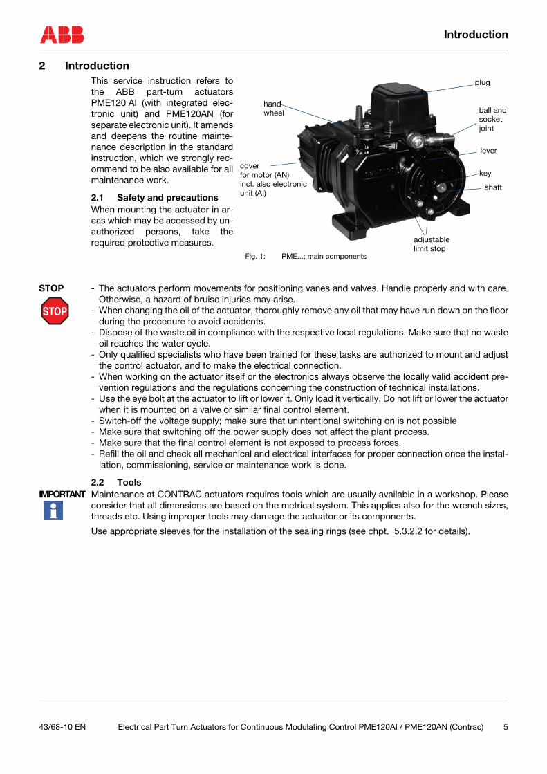
2 IntroductionThis service instruction refers tothe ABB part-turn actuatorsPME120 AI (with integrated elec-tronic unit) and PME120AN (forseparate electronic unit). It amendsand deepens the routine mainte-nance description in the standardinstruction, which we strongly rec-ommend to be also available for allmaintenance work.
2.1 Safety and precautionsWhen mounting the actuator in ar-eas which may be accessed by un-authorized persons, take therequired protective measures.
STOP
STOP - The actuators perform movements for positioning vanes and valves. Handle properly and with care.Otherwise, a hazard of bruise injuries may arise.
- When changing the oil of the actuator, thoroughly remove any oil that may have run down on the floorduring the procedure to avoid accidents.
- Dispose of the waste oil in compliance with the respective local regulations. Make sure that no wasteoil reaches the water cycle.
- Only qualified specialists who have been trained for these tasks are authorized to mount and adjustthe control actuator, and to make the electrical connection.
- When working on the actuator itself or the electronics always observe the locally valid accident pre-vention regulations and the regulations concerning the construction of technical installations.
- Use the eye bolt at the actuator to lift or lower it. Only load it vertically. Do not lift or lower the actuatorwhen it is mounted on a valve or similar final control element.
- Switch-off the voltage supply; make sure that unintentional switching on is not possible- Make sure that switching off the power supply does not affect the plant process.- Make sure that the final control element is not exposed to process forces.- Refill the oil and check all mechanical and electrical interfaces for proper connection once the instal-
lation, commissioning, service or maintenance work is done.
2.2 ToolsIMPORTANT Maintenance at CONTRAC actuators requires tools which are usually available in a workshop. Please
consider that all dimensions are based on the metrical system. This applies also for the wrench sizes,threads etc. Using improper tools may damage the actuator or its components.
Use appropriate sleeves for the installation of the sealing rings (see chpt. 5.3.2.2 for details).
key
lever
handwheel
cover
adjustable
shaft
limit stop
ball andsocketjoint
for motor (AN)incl. also electronicunit (AI)
plug
Fig. 1: PME...; main components
43/68-10 EN Electrical Part Turn Actuators for Continuous Modulating Control PME120AI / PME120AN (Contrac) 5

Actuator versions
3 Actuator versionsPart-tun actuators PME120 are available in two versions:
- PME120 AI (with integrated electronics)- PME120 AN (for separate electronics)
3.1 PME120 AI
Fig. 2: PME120AI with dismounted electronic unit
3.2 PME120AN
Fig. 3: PME120AN with available, separate electronic units
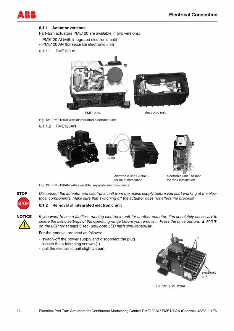
PME120AI electronic unit
PME120AN electronic unit EAN823for field installation
electronic unit EAS822for rack installation
plug
6 Electrical Part Turn Actuators for Continuous Modulating Control PME120AI / PME120AN (Contrac) 43/68-10 EN
Lubrication
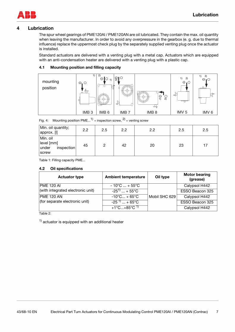
4 LubricationThe spur wheel gearings of PME120AI / PME120AN are oil lubricated. They contain the max. oil quantitywhen leaving the manufacturer. In order to avoid any overpressure in the gearbox (e. g. due to thermalinfluence) replace the uppermost check plug by the separately supplied venting plug once the actuatoris installed.
Standard actuators are delivered with a venting plug with a metal cap. Actuators which are equippedwith an anti-condensation heater are delivered with a venting plug with a plastic cap.
4.1 Mounting position and filling capacity
Fig. 4: Mounting position PME...1) = inspection screw, 2) = venting screw
Table 1: Filling capacity PME...
4.2 Oil specifications
Table 2:
1) actuator is equipped with an additional heater
Min. oil quantity; approx. [l]
2.2 2.5 2.2 2.2 2.5 2.5
Min. oil level [mm]under inspectionscrew
45 2 42 20 23 17
Actuator type Ambient temperature Oil typeMotor bearing
(grease)
PME 120 AI (with integrated electronic unit)
- 10°C ... + 55°C
Mobil SHC 629
Calypsol H442-251) ... + 55°C ESSO Beacon 325
PME 120 AN (for separate electronic unit)
-10°C... + 65°C Calypsol H442-25 1) ... + 65°C ESSO Beacon 325+1°C...+85°C 1) Calypsol H442
IMB 3 IMB 6 IMB 7 IMB 8 IMV 5 IMV 6
1) 2)
1) 2)
1) 2)
1) 2)1) 2)
mounting
position
43/68-10 EN Electrical Part Turn Actuators for Continuous Modulating Control PME120AI / PME120AN (Contrac) 7

Maintenance
4.3 Oil changeUse the lowermost plug to drain the oil. If the actuator basement does not allow to put an appropriatecatchment device under the lowermost drain plug keep this one closed and open the uppermost drainplug. Push the pipe of a hand pump through this opening until the end reaches the bottom. Use thehand pump to get the oil manually out into the catchment device.
NOTICE Do not mix oil for different temperature ranges. Dispose of the waste oil in compliance with the respec-tive local regulations. Make sure that no waste oil reaches the water cycle.
Proceed as follows to drain or change the oil (consider previous hints):
- provide a container capable to take the expected oil quantity acc. to table 1- open or undo the venting plug- unscrew the lowermost inspection screw and use it to drain the oil- make sure that the entire oil is out of the actuator- screw in and tighten the drain plug- complete other maintenance work (if required)- refill the appropriate amount of oil and tighten the venting plug
5 MaintenanceContrac actuators feature a robust construction. As a result, they are highly reliable and require onlylittle maintenance. The maintenance intervals depend upon the effective load.
The built-in microprocessor evaluates the actual load factors (e.g. torques, movements, temperatures,etc.) and derives the remaining operating time until the next routine maintenance is required. Use theconfiguration program for viewing this information.
CAUTION All maintenance work must be carried out by qualified specialists who have been trained for this task.Switch-off the power supply and protect the actuator against unintentional switch-on prior to any main-tenace. Make sure that disconnecting the power or any mechanical linkage does not endanger the anyprocess or person. Make sure that the actuator is not exposed to process forces during the maintenancework.
Apart from the load dependent maintenance intervals determined by the microprocessor we recom-mend routine maintenance at least every 10 years.
The following description of the maintenance work provides that the actuator is disconnected from thedamper and that all electrical supply is disconnected.
8 Electrical Part Turn Actuators for Continuous Modulating Control PME120AI / PME120AN (Contrac) 43/68-10 EN
Maintenance
5.1 Lever
5.1.1 Lever removalIn some case it may be useful to detach the linkage bar from the ball-and-socket-joint, however, it isnot absolutely necessary. Refer to fig. 5 and 6 for the removal procedure!
- screw-off the nut on the lever clamping bolt (1) and put the bolt aside- put an appropriate draw-off tool (2) onto lever and shaft (see fig. 6 for details); make sure that the
claws (3) are symmetrically behind the lever and that the bolt tip is on the shaft center (5)- put a wrench onto the opposite bolt end and turn the bolt; - put the lever carefully aside once it is off the shaft
5.1.2 Lever installation
NOTICE Make sure that the shaft surface and the shaft bore in the lever are clean and free of grease or any otherlubricant
- put the appropriate key into the groove in the shaft- use an expanding srew to spread the lever seat- push a counter part (soft metal) into the lever gap in order to protect the expanding screw thread- push the lever onto the shaft until it is nearly in the same position as it was before- put the lever clamping bolt into the lever and tighten the nut with a torque of 23 Nm (17 lbf-ft)
Fig. 5: Lever mounted on the shaft
1
4
Fig. 6: Use of draw-off tool for lever removal
2
3
34
5
43/68-10 EN Electrical Part Turn Actuators for Continuous Modulating Control PME120AI / PME120AN (Contrac) 9
Maintenance
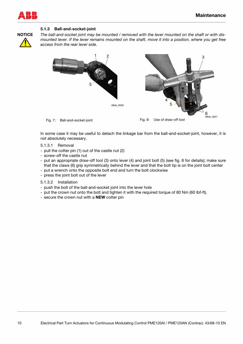
5.1.3 Ball-and-socket-jointNOTICE The ball-and-socket joint may be mounted / removed with the lever mounted on the shaft or with dis-
mounted lever. If the lever remains mounted on the shaft, move it into a position, where you get freeaccess from the rear lever side.
In some case it may be useful to detach the linkage bar from the ball-and-socket-joint, however, it isnot absolutely necessary.
5.1.3.1 Removal- pull the cotter pin (1) out of the castle nut (2)- screw-off the castle nut- put an appropriate draw-off tool (3) onto lever (4) and joint bolt (5) (see fig. 8 for details); make sure
that the claws (6) grip symmetrically behind the lever and that the bolt tip is on the joint bolt center- put a wrench onto the opposite bolt end and turn the bolt clockwise- press the joint bolt out of the lever
5.1.3.2 Installation- push the bolt of the ball-and-socket joint into the lever hole- put the crown nut onto the bolt and tighten it with the required torque of 80 Nm (60 lbf-ft).- secure the crown nut with a NEW cotter pin
Fig. 7: Ball-and-socket-joint
1 2
5
68de_0030
Fig. 8: Use of draw-off tool
3
45
668de_0027
10 Electrical Part Turn Actuators for Continuous Modulating Control PME120AI / PME120AN (Contrac) 43/68-10 EN

Maintenance
5.2 Sealing ring of output drive shaft
Fig. 9: Sectional view of PME120...
123
4
2output shaft
motor
drivepinion
brake
hand wheelmechanism
43/68-10 EN Electrical Part Turn Actuators for Continuous Modulating Control PME120AI / PME120AN (Contrac) 11
Maintenance
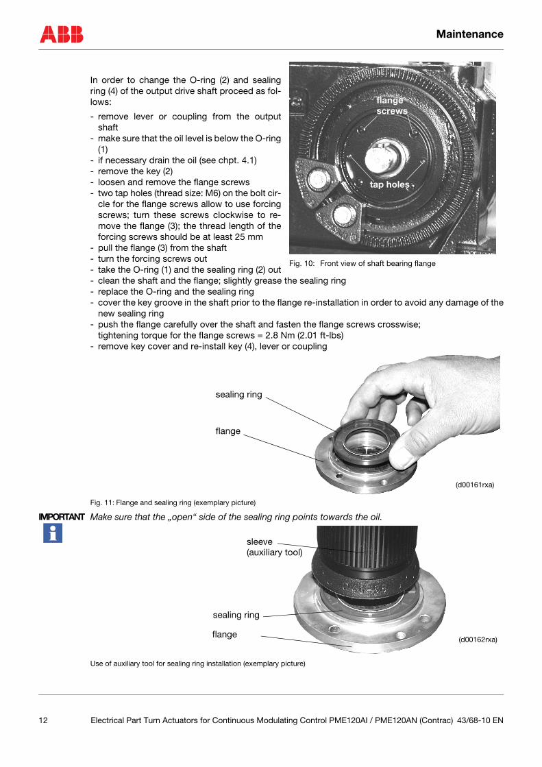
In order to change the O-ring (2) and sealingring (4) of the output drive shaft proceed as fol-lows:
- remove lever or coupling from the outputshaft
- make sure that the oil level is below the O-ring(1)
- if necessary drain the oil (see chpt. 4.1)- remove the key (2)- loosen and remove the flange screws- two tap holes (thread size: M6) on the bolt cir-
cle for the flange screws allow to use forcingscrews; turn these screws clockwise to re-move the flange (3); the thread length of theforcing screws should be at least 25 mm
- pull the flange (3) from the shaft- turn the forcing screws out- take the O-ring (1) and the sealing ring (2) out- clean the shaft and the flange; slightly grease the sealing ring- replace the O-ring and the sealing ring- cover the key groove in the shaft prior to the flange re-installation in order to avoid any damage of the
new sealing ring- push the flange carefully over the shaft and fasten the flange screws crosswise;
tightening torque for the flange screws = 2.8 Nm (2.01 ft-lbs)- remove key cover and re-install key (4), lever or coupling
Fig. 11: Flange and sealing ring (exemplary picture)
IMPORTANT Make sure that the „open“ side of the sealing ring points towards the oil.
Use of auxiliary tool for sealing ring installation (exemplary picture)
tap holes
flange screws
Fig. 10: Front view of shaft bearing flange
sealing ring
flange
(d00161rxa)
sleeve
sealing ring
flange(d00162rxa)
(auxiliary tool)
12 Electrical Part Turn Actuators for Continuous Modulating Control PME120AI / PME120AN (Contrac) 43/68-10 EN
Maintenance
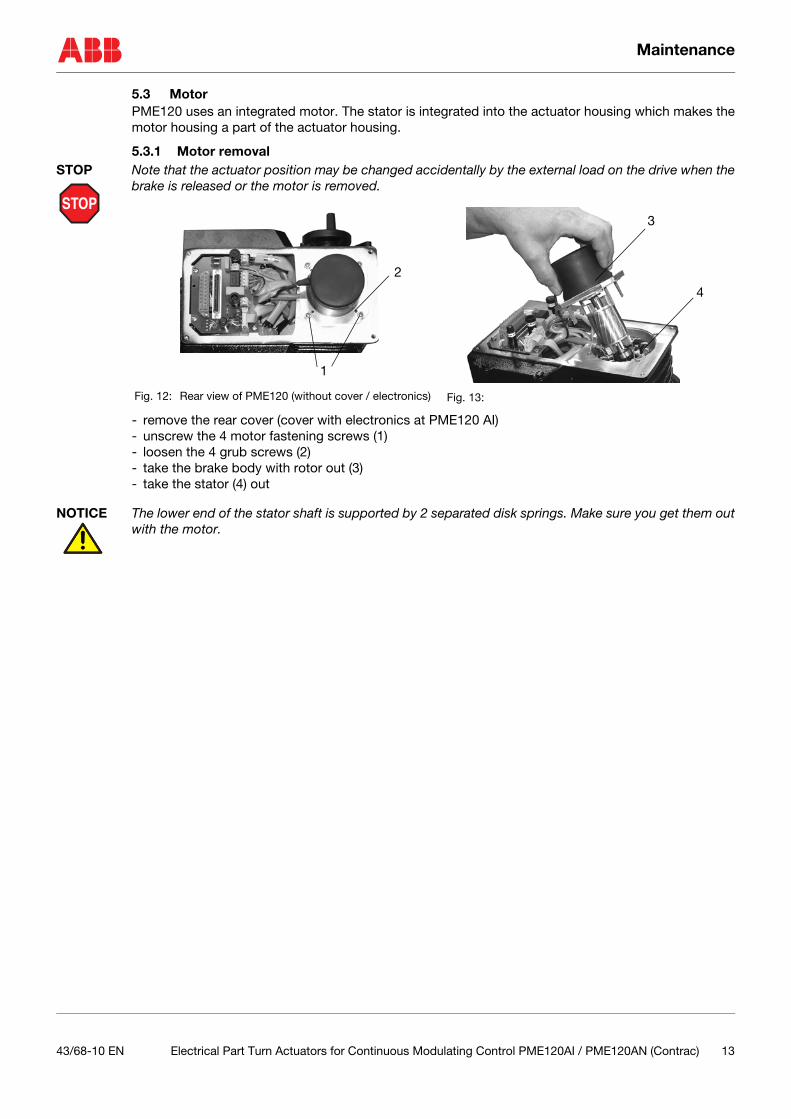
5.3 MotorPME120 uses an integrated motor. The stator is integrated into the actuator housing which makes themotor housing a part of the actuator housing.
5.3.1 Motor removal
STOP
STOP Note that the actuator position may be changed accidentally by the external load on the drive when thebrake is released or the motor is removed.
- remove the rear cover (cover with electronics at PME120 AI)- unscrew the 4 motor fastening screws (1)- loosen the 4 grub screws (2)- take the brake body with rotor out (3)- take the stator (4) out
NOTICE The lower end of the stator shaft is supported by 2 separated disk springs. Make sure you get them outwith the motor.
Fig. 12: Rear view of PME120 (without cover / electronics) Fig. 13:
1
2
3
4
43/68-10 EN Electrical Part Turn Actuators for Continuous Modulating Control PME120AI / PME120AN (Contrac) 13

Maintenance
5.3.2 Motor shaft sealing ringThe motor shaft sealing ring prevents the oil in the gearbox to penetrate into the motor housing.
Once the stator is out, use two appropriate hooks (1) to pull the motor sealing ring (2) out; see fig. 14.
5.3.2.1 Removal
Fig. 14:
5.3.2.2 Installation
Fig. 15:
- grease the new sealing ring and press it in the flange as shown in fig. 15- make sure that the „open“ part of the sealing ring points towards the oil; see fig. 15.- use appropriate squeezer or similar device to press the sealing ring uniformly into the flange (see right
part of fig. 15)
5.3.3 Motor installation- put the stator into the actuator housing- make sure, the hose protected cables are within the groove (see fig. 16)- put the rotor with the brake body into the stator housing- tighten the 4 motor screws- tighten the 4 grub screws to tense rotor / stator housing- use appropriate retainer (DELO-ML 5228 or LOCTITE 243; both medium-firm; detachable) to secure
the grub screws (refer to fig. 12 + 13 for reference no.)
1
sleeve flangesealing ring
oil
squeezer
gearbox
mountingsleeve
14 Electrical Part Turn Actuators for Continuous Modulating Control PME120AI / PME120AN (Contrac) 43/68-10 EN

Electrical Connection
5.4 Brake adjustment
STOP
STOP Note that the actuator position may be changed accidentally by the external load on the drive when thebrake is released or the motor is removed
In automatic mode the brake is permanentlyreleased. Therefore, it is not exposed towear and does usually not require any re-adjustment.
However, if you want to check the brakegap, proceed as follows
- disconnect the actuator from mains sup-ply
- remove hood (PME120AI incl. electronicunit)
- remove the rubber cover of the motor- unscrew the two grub screws (1)- put two thickness gauges (0.15 mm /
0.0059“) diametrically opposed betweenthe two plates (3 + 4)
- press plate 1 down- tighten the two grub screws (1)
6 Electrical Connection
6.1 GeneralThe cable between actuator and electronic unit is connected to the electronic unit via terminals and tothe actuator via a plug. The plug housing may contain a carrier for terminals or for the cable ends withcrimp sockets.
Fig. 17: Exemplary illustration of cable connection to the actuator; plug housing may contain alternatively a terminal car-rier or a crimp carrier.
Fig. 16: Brake (rubber cap removed)
thickness gauge
1
2
3
groove 4
terminal carrier
cables with cable end sleeve
crimp carrier
cables with crimp pins
or
carrier
plug housing
male carrier
43/68-10 EN Electrical Part Turn Actuators for Continuous Modulating Control PME120AI / PME120AN (Contrac) 15
Electrical Connection
6.1.1 Actuator versionsPart-turn actuators PME120 are available in two versions:
- PME120 AI (with integrated electronic unit)- PME120 AN (for separate electronic unit)
6.1.1.1 PME120 AI
Fig. 18: PME120AI with dismounted electronic unit
6.1.1.2 PME120AN
Fig. 19: PME120AN with available, separate electronic units
STOP
STOP Disconnect the actuator and electronic unit from the mains supply before you start working at the elec-trical components. Make sure that switching off the actuator does not affect the process!
6.1.2 Removal of integrated electronic unit
NOTICE If you want to use a faultless running electronic unit for another actuator, it is absolutely necessary todelete the basic settings of the operating range before you remove it. Press the drive buttons on the LCP for at least 5 sec. until both LED flash simultaneously.
For the removal proceed as follows:
- switch-off the power supply and disconnect the plug- loosen the 4 fastening screws (1)- pull the electronic unit slightly apart
PME120AI electronic unit
electronic unit EAN823for field installation
electronic unit EAS822for rack installation
plug
and
1
electronic unit
Fig. 20: PME120AI
16 Electrical Part Turn Actuators for Continuous Modulating Control PME120AI / PME120AN (Contrac) 43/68-10 EN
Electrical Connection
6.2 CoversTerminal covers and other components at the Contracactuators and electronic units are fastened with 4 ormore screws (only 2 screws for local control panel cov-er). In some cases they are additionally sealed with a softrubber gasket. In order to avoid a gap between the hous-ing and the cover (or the other component) tighten thesescrews evenly crosswise according to the order in thebasic sketch in fig. Fig. 21: to get an even load
Start with one screw and tighten it slightly. Then tightenthe 2nd, opposite screw in the same manner. Continue with the remaining screws. Finally tighten thescrews in the same order. This will ensure a tight seal.
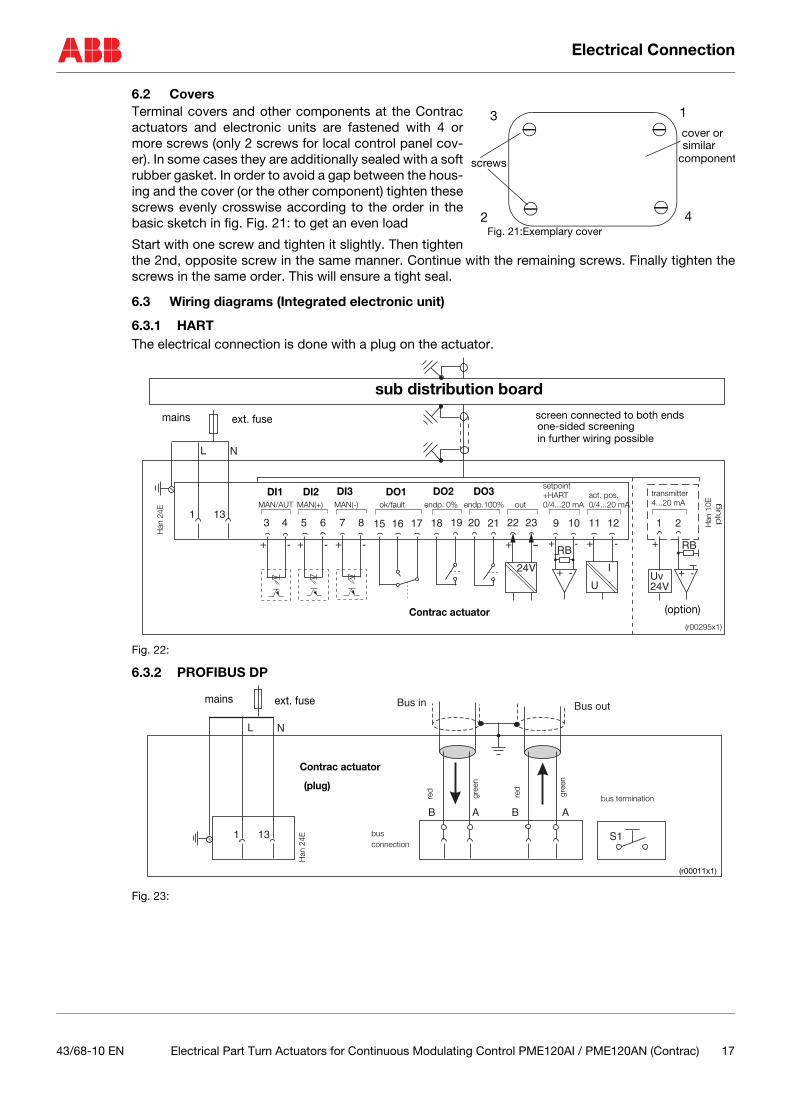
6.3 Wiring diagrams (Integrated electronic unit)
6.3.1 HARTThe electrical connection is done with a plug on the actuator.
Fig. 22:
6.3.2 PROFIBUS DP
Fig. 23:
1
2
3
4
cover or similar
screws
Fig. 21:Exemplary cover
component
24V
11+ - -+
RB
+ -
12
I
U
9 1031
+ - + - + - + -154
13165 176 18 217 19 228 20 23
L N
Uv24V
+RB
+ -
1 2
one-sided screeningin further wiring possible
sub distribution board
screen connected to both endsmains ext. fuse
Han
24E
Contrac actuator
Han
10E
plu
g
(option)
(r00295x1)
MAN/AUTtransmitter4...20 mAMAN(+) MAN(�) ok/fault endp. 0% endp.100% out
setpoint+HART0/4...20 mA
act. pos.0/4...20 mA
DI1 DI2 DI3 DO1 DO2 DO3
1 13
L N
B BA
Bus in Bus out
A
S1
(r00011x1)
mains ext. fuse
Han
24E
bus termination
bus
Contrac actuator
(plug)
connection
red
gree
n
red
gree
n
43/68-10 EN Electrical Part Turn Actuators for Continuous Modulating Control PME120AI / PME120AN (Contrac) 17
Electrical Connection
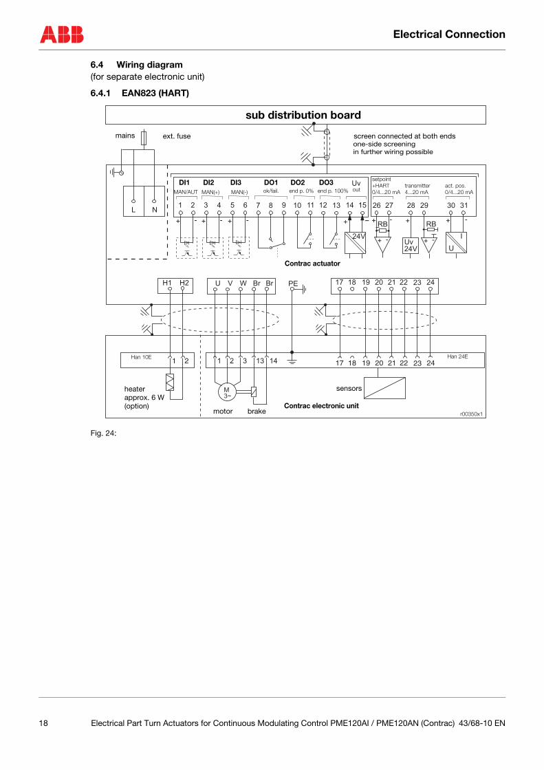
6.4 Wiring diagram (for separate electronic unit)
6.4.1 EAN823 (HART)
Fig. 24:
24V
Uv
30
+ - -+
RB
+ -
31
I
U
26 271
+ - + - + - + -
72 83 94 10 135 11 146 12 15L N
Uv
24V
+
RB
+ -
28 29
17 18 19 20 21 22 23 24
17 18 19 20 21 22 23 24
U V W Br Br
1 21 2 3 13 14
M
3~
H1 H2 PE
r00350x1
one-side screeningext. fuse screen connected at both endsmains
sub distribution board
in further wiring possible
Han 24EHan 10E
motor brake
heaterapprox. 6 W(option)
sensors
Contrac actuator
Contrac electronic unit
MAN/AUT ok/fail.MAN(+) MAN(�) end p. 0% end p. 100% out
setpoint+HART0/4...20 mA
transmitter4...20 mA
act. pos.0/4...20 mA
DI1 DI2 DI3 DO1 DO2 DO3
18 Electrical Part Turn Actuators for Continuous Modulating Control PME120AI / PME120AN (Contrac) 43/68-10 EN
Electrical Connection
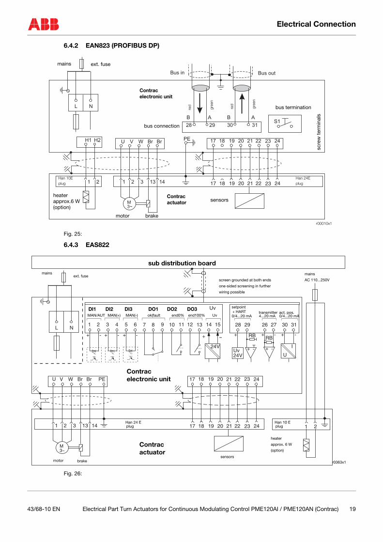
6.4.2 EAN823 (PROFIBUS DP)
Fig. 25:
6.4.3 EAS822
Fig. 26:
L N
Bus outBus in
28 29 30
B BA A
31S1
17 18 19 20 21 22 23 24U V W BrH1 BrH2
17 18 19 20 21 22 23 241 2 3 13 14
M
3~
PE
1 2
r00010x1
ext. fusemains
Han 24E
sensors
motor brake
heaterapprox.6 W(option)
bus termination
bus connection
Han 10E
scre
w t
erm
inal
s
red
gree
n
red
gree
n
Contrac
Contrac electronic unit
plug plug
actuator
24V
Uv
30+ - -+
RB
+ -
31
I
U
26 271
+ - + - + - + -
72 83 94 10 135 11 146 12 15L N
U V W Br Br PE 17 18 19 20 21 22 23 24
17 18 19 20 21 22 23 241 2 3 13 14
M3~
Uv24V
+RB
+ -
28 29
1 2
r0363x1
Contrac
mains
AC 110...250V
sub distribution board
electronic unit
Contrac actuator
heater
approx. 6 W
(option)
sensorsmotor brake
Han 24 Eplug
Han 10 Eplug
mainsext. fuse
MAN/AUT MAN(+) MAN(-) ok(fault end0% end100% Uv
screen grounded at both ends
one-sided screening in further
wiring possible
setpoint
0/4...20 mAact. pos.0/4...20 mA
transmitter4...20 mA
+ HARTDI1 DI2 DI3 DO1 DO2 DO3
43/68-10 EN Electrical Part Turn Actuators for Continuous Modulating Control PME120AI / PME120AN (Contrac) 19
Electrical Connection
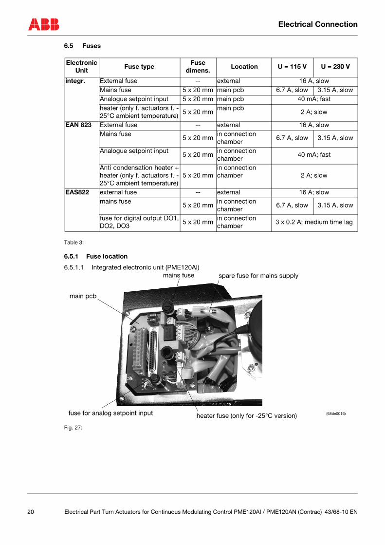
6.5 Fuses
Table 3:
6.5.1 Fuse location
6.5.1.1 Integrated electronic unit (PME120AI)
Fig. 27:
ElectronicUnit
Fuse typeFuse
dimens. Location U = 115 V U = 230 V
integr. External fuse -- external 16 A, slowMains fuse 5 x 20 mm main pcb 6.7 A, slow 3.15 A, slowAnalogue setpoint input 5 x 20 mm main pcb 40 mA; fastheater (only f. actuators f. -25°C ambient temperature)
5 x 20 mmmain pcb
2 A; slow
EAN 823 External fuse -- external 16 A, slowMains fuse
5 x 20 mmin connectionchamber
6.7 A, slow 3.15 A, slow
Analogue setpoint input5 x 20 mm
in connectionchamber
40 mA; fast
Anti condensation heater +heater (only f. actuators f. -25°C ambient temperature)
5 x 20 mmin connection chamber 2 A; slow
EAS822 external fuse -- external 16 A; slowmains fuse
5 x 20 mmin connection chamber
6.7 A, slow 3.15 A, slow
fuse for digital output DO1,DO2, DO3
5 x 20 mmin connection chamber
3 x 0.2 A; medium time lag
mains fuse
fuse for analog setpoint input heater fuse (only for -25°C version) (68de0016)
spare fuse for mains supply
main pcb
20 Electrical Part Turn Actuators for Continuous Modulating Control PME120AI / PME120AN (Contrac) 43/68-10 EN
Electrical Connection
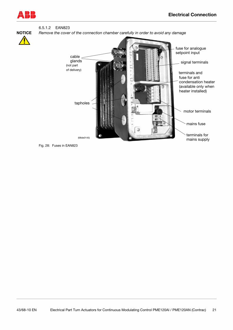
6.5.1.2 EAN823NOTICE Remove the cover of the connection chamber carefully in order to avoid any damage
Fig. 28: Fuses in EAN823
tapholes
signal terminals
motor terminals
terminals for
mains fuse
fuse for anti
fuse for analogue setpoint input
cable
condensation heater
mains supply
glands
terminals and
(available only whenheater installed)
(not part
of delivery)
(68de0145)
43/68-10 EN Electrical Part Turn Actuators for Continuous Modulating Control PME120AI / PME120AN (Contrac) 21
Electrical Connection
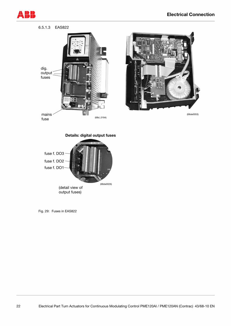
6.5.1.3 EAS822
Fig. 29: Fuses in EAS822
dig. output
mains
fuses
fuse
fuse f. DO1
fuse f. DO2
fuse f. DO3
(detail view ofoutput fuses)
(68de0053)(68d_0184)
(68de0026)
Details: digital output fuses
22 Electrical Part Turn Actuators for Continuous Modulating Control PME120AI / PME120AN (Contrac) 43/68-10 EN
Exchange of position sensor
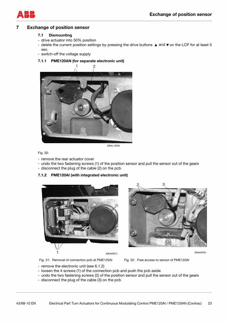
7 Exchange of position sensor
7.1 Dismounting- drive actuator into 50% position- delete the current position settings by pressing the drive buttons on the LCP for at least 5
sec.- switch-off the voltage supply
7.1.1 PME120AN (for separate electronic unit)
Fig. 30:
- remove the rear actuator cover- undo the two fastening screws (1) of the position sensor and pull the sensor out of the gears- disconnect the plug of the cable (2) on the pcb
7.1.2 PME120AI (with integrated electronic unit)
- remove the electronic unit (see 6.1.2)- loosen the 4 screws (1) of the connection pcb and push the pcb aside- undo the two fastening screws (2) of the position sensor and pull the sensor out of the gears- disconnect the plug of the cable (3) on the pcb
Fig. 31: Removal of connection pcb at PME120AI Fig. 32: Free access to sensor of PME120AI
and
(68de_0050)
1 2
1 (68de0051)
2 3
(68de0052)
43/68-10 EN Electrical Part Turn Actuators for Continuous Modulating Control PME120AI / PME120AN (Contrac) 23

Exchange of position sensor
7.2 MountingThe toothed gear pair of the position sensor is held in place by a tension spring (3), to ensure sufficientfree motion when the direction of rotation is reversed
- set the stop pin to the center position, as seen in figure 33- connect the plug of the cable (2) to the sensor pcb- align the sensor and its gears with the actuator; set the first toothed gear in 11:00 o’clock position
(see Figure 33) onto the drive shaft gear (4) - slightly move the sensor back and forth to pre-tension the toothed gears until the second toothed
gear snaps in- fasten the screws (1) tightly.- fasten the rear cover (or cover with electronic unit for PME120Ai if applies)- finally readjust the actuator range as described in the setup section of the actuator and / or electronic
unit instruction manual
Fig. 33: Position sensor Fig. 34: Mounting position (example shows PME120AN)
(d0181rxa)3
(68de0050)
1 2 4
24 Electrical Part Turn Actuators for Continuous Modulating Control PME120AI / PME120AN (Contrac) 43/68-10 EN
Electrical Test Values
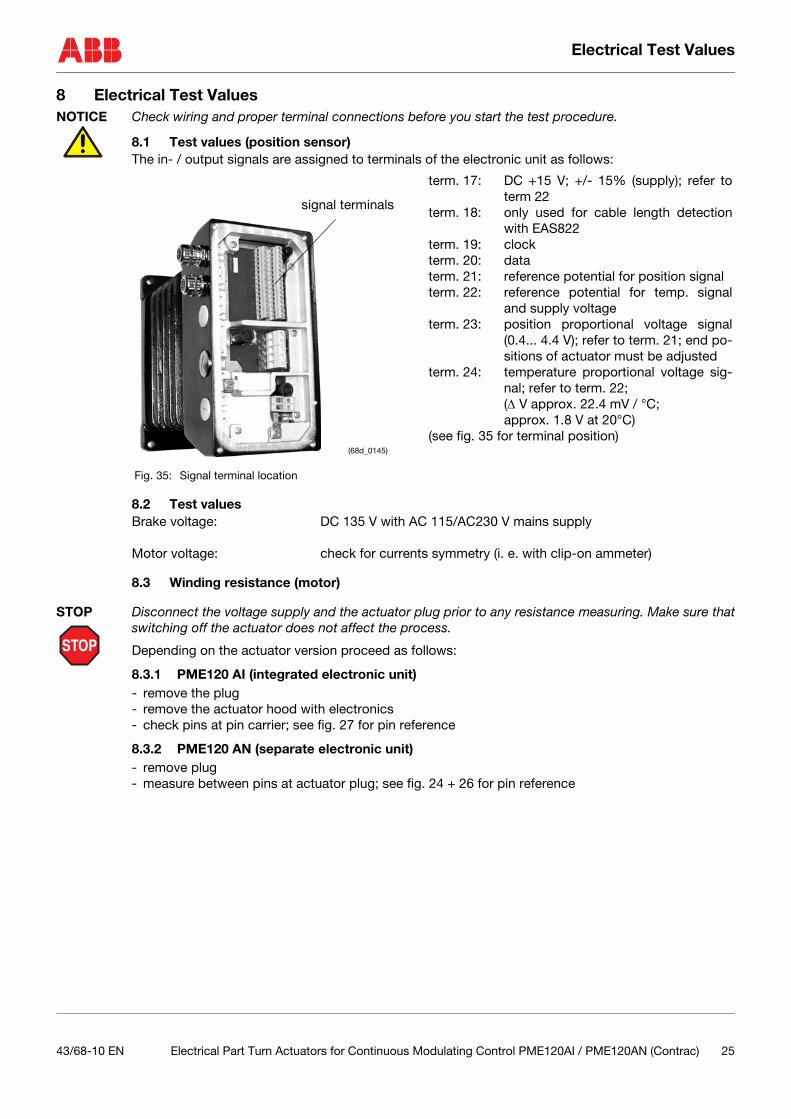
8 Electrical Test ValuesNOTICE Check wiring and proper terminal connections before you start the test procedure.
8.1 Test values (position sensor)The in- / output signals are assigned to terminals of the electronic unit as follows:
8.2 Test valuesBrake voltage: DC 135 V with AC 115/AC230 V mains supply
Motor voltage: check for currents symmetry (i. e. with clip-on ammeter)
8.3 Winding resistance (motor)
STOP
STOP Disconnect the voltage supply and the actuator plug prior to any resistance measuring. Make sure thatswitching off the actuator does not affect the process.
Depending on the actuator version proceed as follows:
8.3.1 PME120 AI (integrated electronic unit)- remove the plug- remove the actuator hood with electronics- check pins at pin carrier; see fig. 27 for pin reference
8.3.2 PME120 AN (separate electronic unit)- remove plug- measure between pins at actuator plug; see fig. 24 + 26 for pin reference
term. 17: DC +15 V; +/- 15% (supply); refer toterm 22
term. 18: only used for cable length detectionwith EAS822
term. 19: clockterm. 20: dataterm. 21: reference potential for position signalterm. 22: reference potential for temp. signal
and supply voltageterm. 23: position proportional voltage signal
(0.4... 4.4 V); refer to term. 21; end po-sitions of actuator must be adjusted
term. 24: temperature proportional voltage sig-nal; refer to term. 22;(∆ V approx. 22.4 mV / °C; approx. 1.8 V at 20°C)
(see fig. 35 for terminal position)
Fig. 35: Signal terminal location
signal terminals
(68d_0145)
43/68-10 EN Electrical Part Turn Actuators for Continuous Modulating Control PME120AI / PME120AN (Contrac) 25

Electrical Test Values
Fig. 36:
Table 4: Winding resistance
Integrated electronic unit(refer to pin carrier in fig. 27)
Separated electronic unit;refer to pin carrier of actuator plug (see fig. 24 + 26)
Resistance
Winding resistance ± 5% at 20° C (motor); pin. 6-7 / 7-8 / 6-8
Winding resistance ± 5% at 20° C (motor); pin. 1-2 / 2-3 / 1-3
3.4 Ohm
Winding resistance ± 5% at 20° C(brake); term. 9 - 10
Winding resistance ± 5% at 20° C(brake); term. 9 - 10
50 Ohm
mains fuse
fuse against active feed at 20 mA setpoint input
heater fuse(68de0016)(only for -25°C version)
spare fuse
9, 10
6, 7, 8
26 Electrical Part Turn Actuators for Continuous Modulating Control PME120AI / PME120AN (Contrac) 43/68-10 EN

Failure detection
9 Failure detection
9.1 LED signals at local control panelProvided the electronic unit is supplied with voltage (green LED on LCP „ON“), the red LED on the localcontrol panel provide some basic status information:
both LED are „OFF“ actuator is okboth LED are „ON“ actuator is in bootstrap mode (e. g. during data loading procedure); in
this case the actuator is not available for the positioning loopboth LED flash simultaneously actuator end positions are not set; actuator does not accept com-
mands to the digital inputs and can only be moved via drive buttons onthe local control panel (see also electronic unit instruction)
both LED flash alternatively actuator failure (e. g. out of adjusted range); actuator can not be movedvia command buttons or commands from the process control system;reset is only possible once the failure reason is eliminated
Fig. 37: Local Control Panel
10 Trouble ShootingNOTICE Check wiring, polarity and all plug and terminal connections before you start detailed trouble shooting.
The following chapter specifies various possible failure events or conditions, which should be checked.Follow the block diagrams to find the associated reason, result or measure to solve the malfunction.
Example:
condition: E6.1 LED signal: Failurepossible failure: E6.3 sensor memory failureone reason / measure to solve the malfct. R6.2 replace sensor; see chpt. 7
(in this case the user will find more detailed in-formation about the sensor replacement inchapter 7)
(68d_0110)
43/68-10 EN Electrical Part Turn Actuators for Continuous Modulating Control PME120AI / PME120AN (Contrac) 27
Trouble Shooting
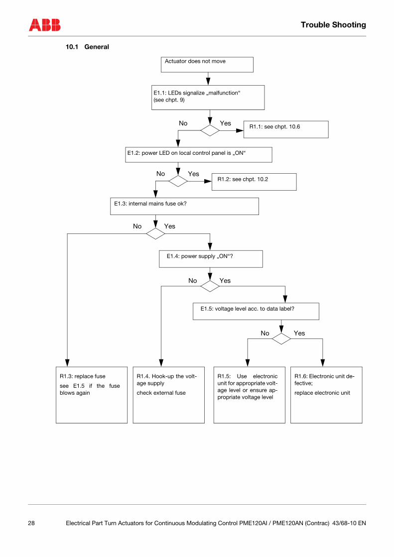
10.1 General
Actuator does not move
E1.1: LEDs signalize „malfunction“(see chpt. 9)
E1.2: power LED on local control panel is „ON“
No
No Yes
E1.3: internal mains fuse ok?
E1.4: power supply „ON“?
E1.5: voltage level acc. to data label?
R1.3: replace fuse
see E1.5 if the fuseblows again
R1.4. Hook-up the volt-age supply
check external fuse
YesNo
YesNo
YesNo
R1.5: Use electronicunit for appropriate volt-age level or ensure ap-propriate voltage level
R1.6: Electronic unit de-fective;
replace electronic unit
Yes
R1.1: see chpt. 10.6
R1.2: see chpt. 10.2
28 Electrical Part Turn Actuators for Continuous Modulating Control PME120AI / PME120AN (Contrac) 43/68-10 EN
Trouble Shooting
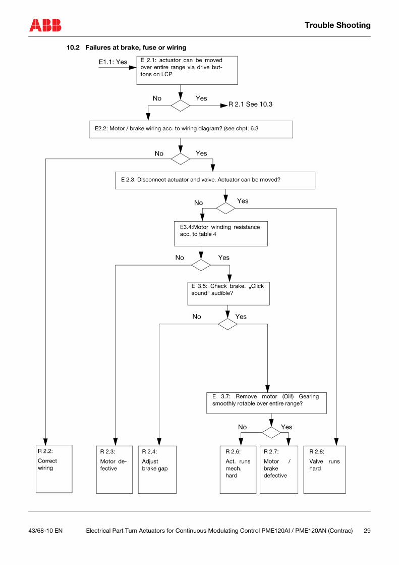
10.2 Failures at brake, fuse or wiring
E 2.1: actuator can be movedover entire range via drive but-tons on LCP
E2.2: Motor / brake wiring acc. to wiring diagram? (see chpt. 6.3
No
E1.1: Yes
No Yes
E 2.3: Disconnect actuator and valve. Actuator can be moved?
No Yes
E3.4:Motor winding resistanceacc. to table 4
E 3.5: Check brake. „Clicksound“ audible?
E 3.7: Remove motor (Oil!) Gearingsmoothly rotable over entire range?
R 2.2:
Correctwiring
R 2.3:
Motor de-fective
R 2.4:
Adjustbrake gap
R 2.6:
Act. runsmech.hard
R 2.7:
Motor /brake defective
R 2.8:
Valve runshard
No Yes
No Yes
No Yes
Yes
R 2.1 See 10.3
43/68-10 EN Electrical Part Turn Actuators for Continuous Modulating Control PME120AI / PME120AN (Contrac) 29

Trouble Shooting
10.3 Operation mode (MAN / AUT)
E 3.1: Actuator is set to AUTOmode via software (A 1 chpt. 10.9)
No Yes
E 2.1: Yes
E 3.2: „Simulation“ modeactive? (D 3 chpt. 10.9)
E 3.3: „Test“ mode ac-tive? (D 2 chpt. 10.9)
Yes
Yes No
No
R 3.1: Set actuator toAUTO mode via confi. soft-ware.
If the actuator is still inMAN mode after switchingon again, change the set-tings for „Behaviour aftervoltage recovery“ to„Switch to AUTO“
(C 2 chpt. 10.9)
R 3.2: De-activate„Simulation“ mode(D 3 chpt. 10.9)
R 3.3: De-activate„Test“ mode(D 2 chpt. 10.9)
R 3.4see chpt. 10.4
(pos. aftersetpoint)
(C 4 chpt.10.9)
R 3.5 see chpt. 10.5
(pos. afterstep control-ler)
(C 4 chpt.10.9)
30 Electrical Part Turn Actuators for Continuous Modulating Control PME120AI / PME120AN (Contrac) 43/68-10 EN

Trouble Shooting
10.4 Input configuration
E 4.1: actuator is set to AUTO mode
(A 1 chpt. 10.9)
E4.2: Fuse for setpoint signal ok? see chpt. 6.5
No
E 3.3: No
E4.3: Setpoint signal measurable and polarityok?
No Yes
Yes
No Yes
R4.1:
De-activate digitalinput contacts(C 4 chpt. 10.9)
Provide „DC 24 V„high“ signal to dig.input 1
R4.2:
Replace
fuse
R4.3:
Provide setpoint signal
E4.4: Setpoint functionadjusted to „analogsetpoint“?(C 4 chpt. 10.9)
YesNo
R4.4:
Select „analogsetpoint“ in userinterface
(C 4 chpt. 10.9)
E4.5: Permanent drivecommand at dig. input2 or 3?
R4.5:
Electronicunitdefective
R4.6:
De-activatepermanentdrive com-mand
YesNo
43/68-10 EN Electrical Part Turn Actuators for Continuous Modulating Control PME120AI / PME120AN (Contrac) 31
Trouble Shooting
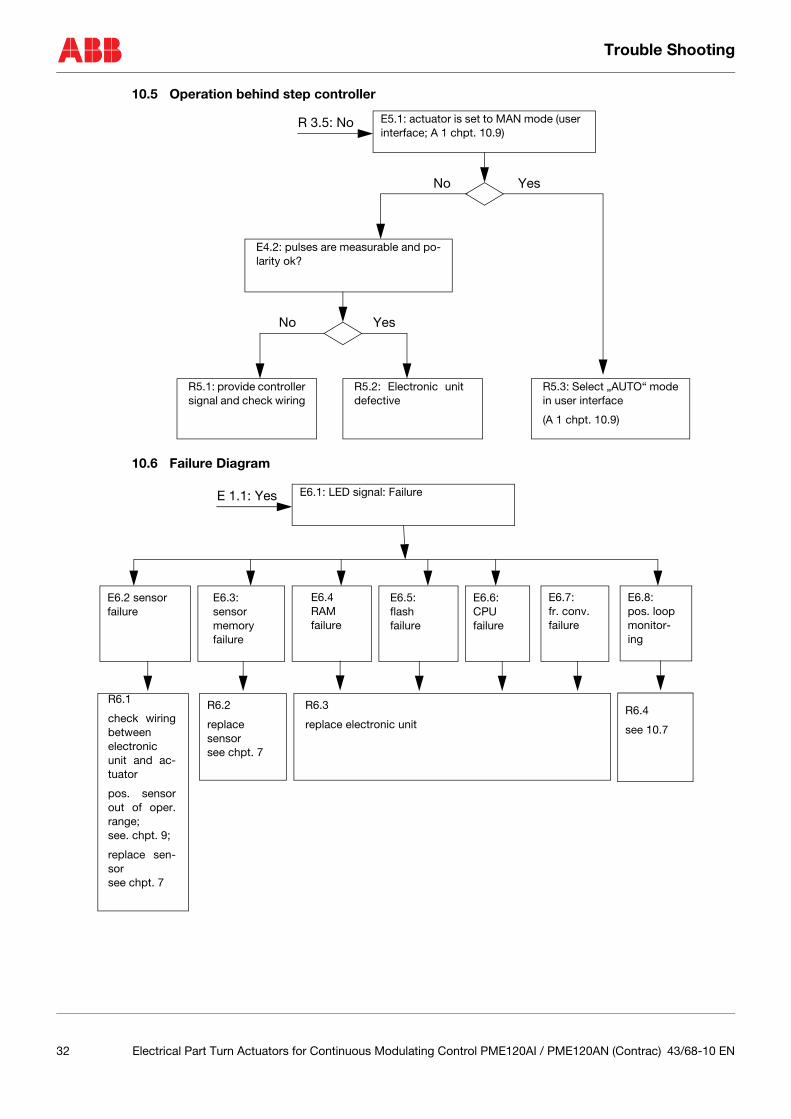
10.5 Operation behind step controller
10.6 Failure Diagram
E5.1: actuator is set to MAN mode (userinterface; A 1 chpt. 10.9)
R 3.5: No
No
R5.3: Select „AUTO“ modein user interface
(A 1 chpt. 10.9)
Yes
E4.2: pulses are measurable and po-larity ok?
Yes
R5.2: Electronic unitdefective
R5.1: provide controllersignal and check wiring
No
E6.1: LED signal: FailureE 1.1: Yes
E6.2 sensor failure
E6.3: sensor memoryfailure
E6.4RAM failure
E6.5:flash failure
E6.6:CPU failure
E6.7:fr. conv.failure
R6.2
replacesensor see chpt. 7
R6.3
replace electronic unit
E6.8:pos. loopmonitor-ing
R6.4
see 10.7
R6.1
check wiringbetweenelectronicunit and ac-tuator
pos. sensorout of oper.range; see. chpt. 9;
replace sen-sor see chpt. 7
32 Electrical Part Turn Actuators for Continuous Modulating Control PME120AI / PME120AN (Contrac) 43/68-10 EN

Trouble Shooting
10.7 Failure due to response of positioning loop monitoring
10.8 General
Actuator runs with creeping speed in one or both end positions
- check the software settings for leaving the end position; if „break-away“ is activated, the actuatormoves with increased torque / force but with reduced speed
Imprecise behaviour in step-control mode
- use graphical user interface to check function assignment of digital input settings; select „stepcontroller“
Actuator over-runs end position(s)
- change the software settings for the end position behaviour to „Position-dependent switch-off“and enter the associated switch-off position
- adjust the mechanical limit stops in order to avoid an end position over-run
Actuator moves into an end position once it reaches a setpoint
- de-activate „close tight“ in the software settings for modulating control near the end position
Actuator position does not correspond to setpoint although the position signal corresponds to the setpoint
- de-activate the progammable setpoint in the software settings for the setpoint characteristic
Actuator follows the setpoint only within a limited range
- de-activate „split range“ in the software settings for the setpoint characteristic
E 7.1: Failure due to positioning loop monitoring
(C 5 chpt. 10.9)R 6.4:
E7.2
speed monitoring
E7.3
stand still monitoring
E7.4
wrong moving direction
E7.5
Moves too heavy inend position(rough-running)
R7.1
actuator can not fol-low the setpointwith adjusted speed
rough-running actuator
R7.2
actuator has left theposition withoutcommand
R7.3
actuator has movedinto wrong direction
R7.4
check end positionconditions (depositsmay cause frictionand slow down theactuator)
43/68-10 EN Electrical Part Turn Actuators for Continuous Modulating Control PME120AI / PME120AN (Contrac) 33
Trouble Shooting
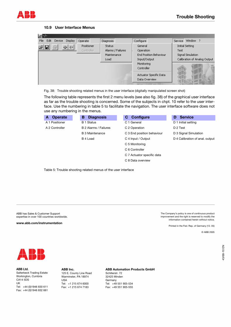
10.9 User Interface Menus
Fig. 38: Trouble shooting related menus in the user interface (digitally manipulated screen shot)
The following table represents the first 2 menu levels (see also fig. 38) of the graphical user interfaceas far as the trouble shooting is concerned. Some of the subjects in chpt. 10 refer to the user inter-face. Use the numbering in table 5 to facilitate the navigation. The user interface software does notuse any numbering in the menus.
Table 5: Trouble shooting related menus of the user interface
A Operate B Diagnosis C Configure D Service A 1 Positioner B 1 Status C 1 General D 1 Initial setting
A 2 Controller B 2 Alarms / Failures C 2 Operation D 2 Test
B 3 Maintenance C 3 End position behaviour D 3 Signal Simulation
B 4 Load C 4 Input / Output D 4 Calibration of anal. output
C 5 Monitoring
C 6 Controller
C 7 Actuator specific data
C 8 Data overview
43/6
8-10
EN
ABB has Sales & Customer Supportexpertise in over 100 countries worldwide.
www.abb.com/instrumentation
The Company’s policy is one of continuous productimprovement and the right is reserved to modify the
information contained herein without notice.
Printed in the Fed. Rep. of Germany (12. 05)
© ABB 2005
ABB Ltd.Salterbeck Trading EstateWorkington, CumbriaCA14 5DSUKTel: +44 (0)1946 830 611Fax: +44 (0)1946 832 661
ABB Inc.125 E. County Line RoadWarminster, PA 18974USATel: +1 215 674 6000Fax: +1 215 674 7183
ABB Automation Products GmbHSchillerstr. 7232425 MindenGermanyTel: +49 551 905-534Fax: +49 551 905-555