Embed Size (px)
Citation preview

DTE
CHAPTER 11
OF THE
SERVICE INSTALLATION MANUAL
(GREEN BOOK)
2021 REVISION
Editor: Shaji T Kurian

2021 PRIMARY SERVICES INDEX
SIM-ESIG SIM-ESIG:INDEX-11.PS
SECTION 11
GENERAL
Installation Policies and Routines.....................................................11-1-1 to 11-1-8Service Cable Installation..............................................................11-2-1 and 11-2-2
EQUIPMENT ARRANGEMENT
Padmount Transformer and Switch..................................................11-3-1 to 11-3-2Outdoor Primary Cable Enclosure...................................................................11-3-3Grounding spec. – customer transformer pad .................................................11-3-4Clearance Requirements.................................................................................11-3-5
METERING
Equipment Location ........................................................................................11-4-1Potential Transformer Fusing ..........................................................................11-4-2Equipment Arrangement ...............................................................11-4-3 and 11-4-6Metering Cubicle .............................................................................................11-4-7Typical Outdoor Metering Unit..........................................................11-4-8 to 11-4-9Wiring and Installation Instructions............................................ 11-4-10 to 11-4-12BOutdoor Wiring and Installation Instructions ……………………………………11-4-13Current and Potential Transformer Dimensions ...........................11-4-14 to 11-4-17
ACCEPTABLE MATERIALS
Service Cable..................................................................................................11-5-1Terminations and Splices ................................................................................11-5-2Fused Loadbreak Interrupter Switches............................................................11-5-3
SERVICE EQUIPMENT
Loadbreak Switchgear Requirements ............................................11-5-4 to 11-5-16General Switchgear Arrangement Drawings ................................11-5-17 to 11-5-28
ALTERNATE SERVICES
Subtransmission Power Services…………………………………….. 11-6-1 to 11-6-3
APPENDIX
Service entry compartment & Control drawings……………………...………. 11-7-00

2021 PRIMARY SERVICES 11-1-1
SIM-ESIG
PRIMARY SERVICE INSTALLATIONS
PRIMARY METERED PRIMARY, SECONDARY METERED PRIMARYAND INDUSTRIAL SUBSTATION INSTALLATIONS
A. General
1. Purpose
The following instructions and specifications are intended to set forth the generalpractices and procedures to be followed in connection with customer primary andhigh voltage installations. These instructions define the areas in which assistancemay be given to a primary customer to coordinate the customer’s and DTE Electricsystems, to increase the operating safety of high voltage equipment.
2. Definition of Primary Installation
A primary customer is one who takes service directly from DTE Electric primarylines (4800V and above) through primary facilities located on customer premises.The character and arrangement of these facilities vary according to the location ofthe customer, the size and type of load, and the number of lines from DTE Electricsystem. The facilities that must be provided by the customer could include any orall the following elements:
(a) DTE Primary service connections to overhead or underground lines.
(b) Primary circuit breakers or fused loadbreak interrupters.
(c) Primary step-down transformers, motors, and other primary equipment.
(d) Primary meter compartment to house DTE Electric revenue instrumenttransformers.
These facilities on the customer’s premises, including all associated DTE andcustomer owned equipment and parts involved in maintaining primary service up tothe point of direct utilization or transformation, make up what is known as thePrimary Installation.
3. Definition of High Voltage Industrial Substation
In addition to the Primary Installation, there may be a DTE or customer owned highvoltage substation (Class “I”) on the customer’s premises to reduce the utilityservice voltage to the customer’s utilization voltage. The high voltage substationand the high voltage lines feeding the substation are not considered part of thePrimary Installation and are treated separately in these instructions.

2021 PRIMARY SERVICES 11-1-2
SIM-ESIG
B. General Policy
Customer is solely responsible for its practices, personnel, contractors, services and equipment.DTE’s requirements, recommendations, inspections, and/or approvals referenced herein shall inno way relieve customer of its responsibilities or liability for its equipment, services, personnel,practices or contractors. Customer and DTE agree that DTE is in no way liable for any ofcustomer’s work, installation, services, or equipment or the maintenance thereof. Customer isresponsible for ensuring that its equipment, practices, services, and installation meets allapplicable federal, state, local, and industry standards, laws and regulations.
1. Customer Responsibilities
The customer will design, build, own, and maintain the complete PrimaryInstallation except line breakers or any switchgear that is part of the DTE system.Generally, DTE will design, build, own, operate, and maintain any associated highvoltage substation and high voltage lines feeding the substation except for thosecustomers taking service under the Alternative Primary Supply Rate. Customerinstallations shall not affect the reliability of service furnished to other customers.The general policy is as follows:
(a) Primary Installations:
(1) The customer’s electrical system and its installation shall conform to thelatest version of the National Electrical Code (NEC), IEEE NationalElectric Safety Code (NESC), local municipal codes, and DTE’srequirements.
(2) New installations: The customer will design, build, own, operate, andmaintain the complete Primary Installation. DTE will furnish, own, andmaintain such revenue metering. It is a requirement for the customer thatArc Flash and approach distances calculations are performed forequipment before it is commissioned. The Arc Flash and DistancesValues will be posted/labeled on the front of equipment. Maintenance ofprimary switchgear by the customer will be in accordance with therecommendations of the switchgear manufacturer.
(3) Existing installations: The adequate short circuit current interruptingcapability of the primary switchgear is the customer’s responsibility.
(4) Primary fuses: Primary fuses will be owned and maintained by DTE iflocated on a DTE owned pole or primary switch cabinet; otherwise, theywill be owned and maintained by the customer.

2021 PRIMARY SERVICES 11-1-3
SIM-ESIG
(b) Generation Facilities
The general policy and requirements for the interconnection of generation onthe DTE system are contained in the ‘Electric Utility Interconnection & NetMetering’, which can be found on the MPSC (Michigan Public ServiceCommission) or DTE Energy websites Interconnection Process | DTE Energy.
Any generator or regenerative source (e.g. fuel cell, wind turbine ordynamometer) that operates in parallel with DTE’s electrical system mustadhere to these guidelines. The primary installation requirements contained inthis chapter also apply. No generation facility shall be allowed to connect tothe DTE system until all requirements are met and final installation approval isgranted by DTE Primary Services.
2. Company Responsibilities
The DTE Account Manager is responsible for all negotiations with the PrimaryCustomer pertaining to high voltage and primary installations on customerpremises. DTE Primary Services will follow matters of design, acceptance,inspection, and testing, as well as customer operation and maintenance of theinstallation. The DTE Account Manager will see that the designated partiesproperly carry out all steps in these instructions in accordance with the prescribedprocedure.
C. Primary Installations
1. Design
The general design of a new Primary Installation is to be coordinated by DTEPrimary Services and the customer’s representatives. Contract drawings andspecifications covering customer substation installation, including service entranceswitchgear shall be submitted to DTE for review and approval prior to their releasefor contractual bidding. These also include one-line, three-line diagram, plandetails of switchgear installation, and grounding system. Detailed equipment shopsdrawings (one-line, three-line, control schematic & wiring) are to be furnished bythe manufacturer (IEEE device numbers should be used) and submitted to DTE forreview and approval prior to the construction. DTE Primary Services will approvethe design and installation of any private overhead or underground line that isextended from the DTE point of service to the main primary equipment. Alldrawings and designs are to be approved through DTE Primary Services.

2021 PRIMARY SERVICES 11-1-4
SIM-ESIG
2. Equipment
The size and class of primary switchgear or fused loadbreak interrupters and thecharacteristics of the primary fuses are to be specified by DTE Primary Services. Inthe interest of safety and service continuity to the customer, the equipmentfurnished must be acceptable to DTE. Relays, fuses, and control equipment will bedesigned so that their operation is coordinated with that of the protectiveequipment on the DTE system. This is subject to approval by the DTE SystemProtection and Automation group. DTE requires control scheme interlocks to behard wired breaker contacts. A ground detection scheme must be installed whenconnecting to the 4.8kV underground delta system. Provision will be made for DTEHazardous Energy Control (HEC) points subject to DTE Primary Servicesapproval.
3. Supervision
DTE Primary Services group will follow the construction of all Primary Installationsto see that all details are in accordance with the approved drawings, and all DTErequirements and specifications.
4. Inspection
Before the installation is placed in commission, DTE Primary Services willdetermine that the unmetered overhead and underground lines on the customer’spremises are completed and ready to be energized. Until the lines are ready to beenergized, the rules and procedures established for lines in the out-of-commissionstate must be observed.
DTE Primary Services will inspect the primary switchgear, metered overhead andunderground lines, transformers, and generator before they are energized.
5. Connecting Service
When the installation has been accepted for connection, DTE Primary Services willnotify the customer that the installation is to be energized and will request theSystem Supervisor or the Lines Department to make the connection to the DTEsystem. The operation of the installation is the customer's responsibility. DTEPrimary Services may be available, in an advisory capacity, to inform the customeras to the operation and maintenance of the equipment.
2021 PRIMARY SERVICES 11-1-5
SIM-ESIG
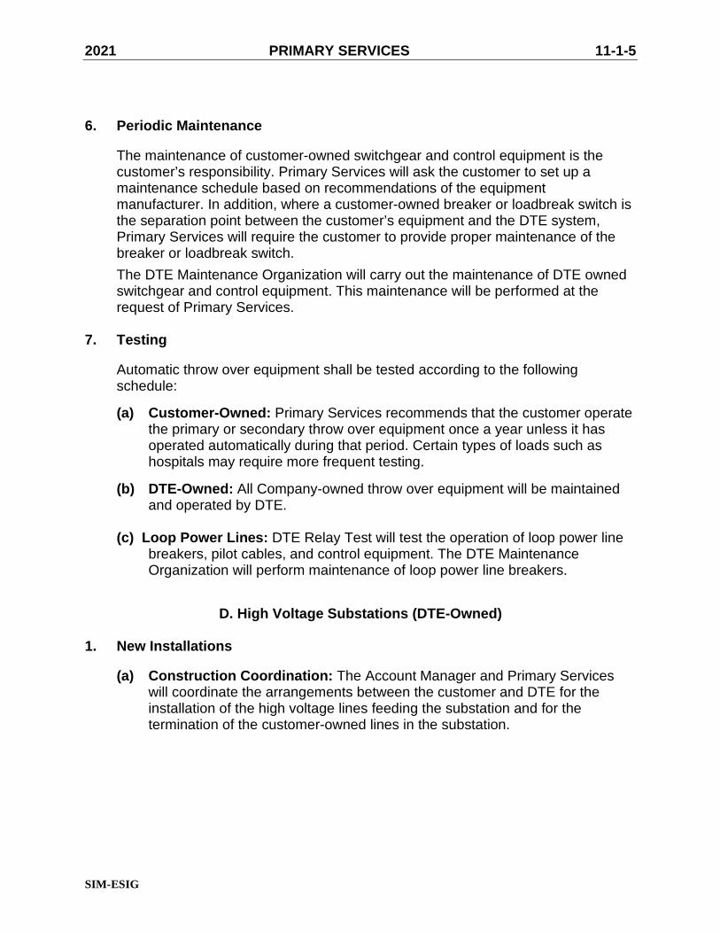
6. Periodic Maintenance
The maintenance of customer-owned switchgear and control equipment is thecustomer’s responsibility. Primary Services will ask the customer to set up amaintenance schedule based on recommendations of the equipmentmanufacturer. In addition, where a customer-owned breaker or loadbreak switch isthe separation point between the customer’s equipment and the DTE system,Primary Services will require the customer to provide proper maintenance of thebreaker or loadbreak switch.
The DTE Maintenance Organization will carry out the maintenance of DTE ownedswitchgear and control equipment. This maintenance will be performed at therequest of Primary Services.
7. Testing
Automatic throw over equipment shall be tested according to the followingschedule:
(a) Customer-Owned: Primary Services recommends that the customer operatethe primary or secondary throw over equipment once a year unless it hasoperated automatically during that period. Certain types of loads such ashospitals may require more frequent testing.
(b) DTE-Owned: All Company-owned throw over equipment will be maintainedand operated by DTE.
(c) Loop Power Lines: DTE Relay Test will test the operation of loop power linebreakers, pilot cables, and control equipment. The DTE MaintenanceOrganization will perform maintenance of loop power line breakers.
D. High Voltage Substations (DTE-Owned)
1. New Installations
(a) Construction Coordination: The Account Manager and Primary Serviceswill coordinate the arrangements between the customer and DTE for theinstallation of the high voltage lines feeding the substation and for thetermination of the customer-owned lines in the substation.

2021 PRIMARY SERVICES 11-1-6
SIM-ESIG
(b) DTE and Customer Responsibilities: The high voltage substation (DTE-owned) serving one customer and located on customer premises is to bedesigned, built, owned, operated, and maintained by DTE. The customermust lease or provide an easement for the substation site to DTE and provideaccess to the site for DTE employees and equipment.
The customer must also provide rights-of-way across their property for thelines feeding the substation. If these are overhead lines, DTE will install, own,and maintain them. If underground construction is used, the customer will doall trenching and install, own, and maintain all conduit and manholes on theirproperty to the substation site. DTE will install, own, and maintain the cablesto feed the substation. The customer conduit/manhole must meet all DTErequirements.
The customer will install, own, and maintain the conductors from thesecondary make-up bus (DTE-owned interconnection point) of the substationto their Primary Installation (Service Point). At the customer's expense, DTEwill provide and install all conduit, racks, or supports required for theseconductors within the substation site. The secondary conductors from theinterconnection point to the Service Point fall under NESC jurisdiction. Thecustomer’s Primary Installation falls under NEC jurisdiction.
(c) Minimum Design Requirements: The customer shall meet the followingdesign requirements for DTE-owned High Voltage Substations:
i. Secondary Main Breakerii. Current Transformers (CTs) on load side of secondary main breaker for
DTE transformer differential protection. Minimum accuracy class of C400(consult with DTE Primary Services for CT ratio)
iii. Load shed provisions may be required – ‘Trip and Lock Out’ secondarymain breaker (consult with DTE Primary Services)
(d) Energizing: When the substation has been given final approval by SystemEngineering, DTE Primary Services will notify the customer and, at the sametime, make certain that energizing the equipment up to the primary breaker orequivalent will not cause a hazard on any part of the installation. When allsafety precautions have been attended to, DTE Primary Services will requestthe System Supervisor to have the substation energized.
2. Existing Installations
Maintenance: DTE will maintain at its expense all overhead lines and allunderground cables on the customer's property feeding the high voltagesubstation. The customer will maintain the conduit and manhole system for theunderground cables.

2021 PRIMARY SERVICES 11-1-7
SIM-ESIG
E. High Voltage Substations (Customer-Owned)
Some high voltage substations are customer-owned to meet the requirement of certainrate applications:
1. Bulk Power Supply.
Customers will own the supply lines and high voltage substations on theirpremises. The design, supervision, testing, and operation shall be as described inparagraphs 1 through 7 beginning on page 11-1-3.
2. New Installations.
(a) Construction Coordination. The design of customer-owned high voltagesubstations shall be as described in paragraphs 1 and 2 under C. PrimaryInstallations. The DTE Account Manager and DTE Primary Services shallcoordinate the arrangements between the customer and DTE for theinstallation of the high voltage lines feeding the substation.
(b) Customer and DTE Responsibilities. The customer must provide right-of-way across their property for the lines feeding the substation. If these areoverhead lines, the customer will install, own, and maintain them. Ifunderground construction is used, the customer will do all trenching andinstall, own, and maintain all conduit and manholes on their property. Thecustomer will install, own, and maintain the cables to feed the substation.
(c) Supervision. DTE Primary Services shall follow the construction of thesubstation to see that all details are in accordance with the approveddrawings and that the workmanship is according to acceptable standards.
(d) Inspection. DTE Electric shall make only such inspections, as it deemsnecessary for the protection & safety of other customers and the public.Additional tests may be requested by DTE Primary Services.

2021 PRIMARY SERVICES 11-1-8
SIM-ESIG
(e) Service Connection.
When the installation has been approved for connection, DTE PrimaryServices will request the DTE System Supervisor to have the substationenergized. The same precautions regarding hazards taken with DTE ownedsubstations shall be observed. The operation and maintenance of theinstallation is the customer’s responsibility. DTE Primary Services may beavailable, in an advisory capacity, to inform the customer as to the operationand maintenance of the equipment.
F. Primary Installations Built for 13.2 kV
All new primary installations are to be built for 13.2 kV operations, even though theinstallation may be operated initially at 4.8 kV or 8.32 kV. A letter from the AssignedAccount Manager must confirm any exception to this policy.
Any questions pertaining to the above or other primary metered installationsshould be directed to the DTE Primary Services Group at 313.235.6471.
2021 PRIMARY SERVICES 11-2-1
SIM-ESIG
PRIMARY SERVICE CABLE INSTALLATION
TO DTE CABLE POLE OR MANHOLE
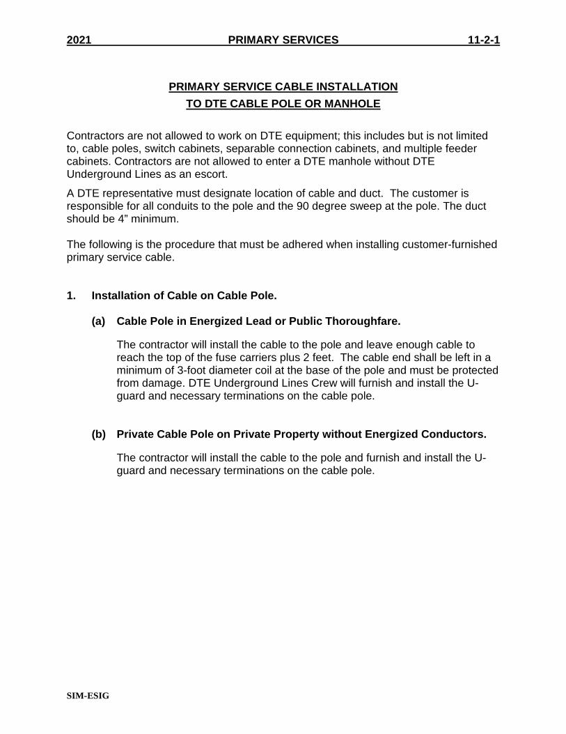
Contractors are not allowed to work on DTE equipment; this includes but is not limitedto, cable poles, switch cabinets, separable connection cabinets, and multiple feedercabinets. Contractors are not allowed to enter a DTE manhole without DTEUnderground Lines as an escort.
A DTE representative must designate location of cable and duct. The customer isresponsible for all conduits to the pole and the 90 degree sweep at the pole. The ductshould be 4” minimum.
The following is the procedure that must be adhered when installing customer-furnishedprimary service cable.
1. Installation of Cable on Cable Pole.
(a) Cable Pole in Energized Lead or Public Thoroughfare.
The contractor will install the cable to the pole and leave enough cable toreach the top of the fuse carriers plus 2 feet. The cable end shall be left in aminimum of 3-foot diameter coil at the base of the pole and must be protectedfrom damage. DTE Underground Lines Crew will furnish and install the U-guard and necessary terminations on the cable pole.
(b) Private Cable Pole on Private Property without Energized Conductors.
The contractor will install the cable to the pole and furnish and install the U-guard and necessary terminations on the cable pole.

2021 PRIMARY SERVICES 11-2-2
SIM-ESIG
2. Installation of Cable in a DTE Manhole
(a) Responsibilities. The DTE Crew will rig the DTE manhole and the contractorwill pull cable between that manhole and the first private manhole or vault.The contractor will furnish all reels, jacks, lines, cable grips, and all labor andequipment necessary to pull the cable. The contractor will cut the cable offreels and the DTE Crew will train the cable in the DTE manhole. The DTECrew will furnish labor and material for splicing. A steel pulling line will bepermitted for pulling cable between manholes. Cable ends should be sealedbefore installation. The DTE Crew will reseal the ends in the DTE manhole ifnecessary.
(b) Scheduling. DTE Primary Services will schedule the pulling and terminatingof the cable with the contractor and the DTE Underground Line Crew forprimary metered installations. Minimum of eleven working days should beallowed for crew scheduling and the contractor should be ready on thescheduled date. When ITC is involved minimum 20 working days will bethe requirement.

SIM-ESIG
2021 11-3-1PRIMARY SERVICE
DTEPRIMARY SERVICES
OR DAMAGE ARISING FROM THE USE OF THIS SPECIFICATION DIAGRAM.
DTE ASSUMES NO RESPONSIBILITY FOR INJURY
OUTDOOR PRIMARY COMBINATION UNIT & PAD MOUNTED TRANSFORMER
FOR USE WITH TRANSFORMERS OF 1500 KVA OR LESS
EXAMPLE 1
ON
E L
INE
DIA
GR
AM
EL
EV
AT
ION
OF
MA
T
CO
MB
INA
TIO
N S
WIT
CH
/
CO
ND
UIT
FO
R S
EC
ON
DA
RIE
S
TO
BE
DE
TE
RM
INE
D B
Y O
TH
ER
S
SIZ
E,
NU
MB
ER
AN
D T
ER
MIN
AT
ION
TR
AN
SF
OR
ME
R
1 1
/2" M
IN
AN
D O
UT
DO
OR
ME
TE
RIN
G U
NIT
TR
AN
SF
OR
ME
R M
OU
NT
ING
LU
GS
TH
E U
SE
OF
"P
IER
S" M
AY
WIT
HO
UT
TIP
PIN
G O
R C
RA
CK
ING
.
DE
SIG
NE
D B
Y O
TH
ER
S T
O C
AR
RY
EX
TE
ND
GR
OU
ND
CO
ND
UC
TO
RS
(2
)
AF
TE
R E
QU
IPM
EN
T I
S D
EL
IVE
RE
D
WE
IGH
T O
F T
RA
NS
FO
RM
ER
3' A
BO
VE
MA
T
TR
AN
SF
OR
ME
R
15
00
KV
A
CA
BL
E P
OL
E
FU
SE
CO
MB
INA
TIO
N U
NIT
SW
ITC
H/M
ET
ER
CO
MB
INA
TIO
N U
NIT
SW
ITC
H/M
ET
ER
SE
E S
IM/E
SIG
PA
GE
3-6
-10
NE
CE
SS
AR
Y
INS
TA
LL
GU
AR
D P
OS
TS
IF
OR
LE
SS
6 C
OP
PE
RW
EL
D G
RO
UN
D R
OD
S M
INIM
UM
5/8
'' D
IAM
ET
ER
X 8
' L
ON
G,
SP
AC
ED
10
" M
AX
IMU
M C
EN
TE
RL
INE
TO
CE
NT
ER
LIN
E.
MA
XIM
UM
GR
OU
ND
RE
SIS
TA
NC
E -
5 O
HM
S
GR
OU
ND
RO
DS
AR
E T
O B
E
INS
TA
LL
ED
OU
TS
IDE
CO
NC
RE
TE
PA
D.
AN
Y D
EV
IAT
ION
S M
US
T
BE
AP
PR
OV
ED
AN
D I
NS
PE
CT
ED
BE
FO
RE
PO
UR
ING
CO
NC
RE
TE
PA
D.
GR
OU
ND
WIR
E S
HA
LL
BE
4/0
BA
RE
ST
RA
ND
ED
WIR
E
DO
UB
LE
SP
LIT
BO
LT
CO
NN
EC
TO
RS
(B
RO
NZ
E)
1 1
/2" R
IGID
ST
EE
L
CO
ND
UIT
TO
DT
E
ME
TE
RS
. L
OC
AT
ION
TO
BE
DE
TE
RM
INE
D O
N J
OB
.
SE
E D
TE
PR
IMA
RY
RE
P.
EX
TE
ND
GR
OU
ND
WIR
E
3' A
BO
VE
MA
T
SE
AL
SE
RV
ICE
CA
BL
E D
UC
T
WIT
H D
UC
T S
EA
L O
R
EQ
UIV
AL
EN
T M
AT
ER
IAL
3/4
'' C
ON
DU
IT F
OR
CO
MB
INA
TIO
N H
EA
TE
R
8''
8 7
/8''
2' 4
''
2' 5
''
2' 3
''2'
1' 9
''10' 3''
2'
14
'
GR
OU
ND
MA
T T
O B
E I
NS
PE
CT
ED
BY
PR
IMA
RY
SE
RV
ICE
PE
RS
ON
NE
L B
EF
OR
E P
OU
RIN
G C
ON
CR
ET
E
RE
INF
OR
CE
D C
ON
CR
ET
E M
AT
.
BE
NE
CE
SS
AR
Y.
INS
TA
LL
1/2
" A
NC
HO
RS
TO
SU
IT
OR
LE
SS
15
00
KV
A
TR
AN
SF
OR
ME
R
4''
CO
ND
UIT
CO
UP
LIN
G
GR
OU
ND
RO
D
AP
PR
OV
ED
EQ
UA
L
ILS
CO
GP
L-6
OR
GC
-103-0
2 C
AD
WE
LD
,
AN
DE
RS
ON
BR
AS
S
GR
AD
E
4''
BE
LO
W F
INA
L
RO
D S
HA
LL
BE
TO
P O
F G
RO
UN
D
GR
AD
E
LIN
E
GR
AD
E
LIN
E
LO
AD
ME
TE
R U
NIT
4''
4''
2'
6''
6''
6''
2.
1.
NO
TE
S:
OF
GR
OU
ND
MA
T P
RIO
R T
O P
OU
RIN
G C
ON
CR
ET
E.
5. IM
PO
RT
AN
T -
CA
LL
PR
IMA
RY
SE
RV
ICE
S F
OR
IN
SP
EC
TIO
N
MU
ST
BE
2 I
NC
HE
S. N
O S
EC
ON
DA
RY
RU
NS
> 2
00' P
ER
MIT
TE
D.
(AP
PR
OV
ED
BY
PR
IMA
RY
SE
RV
ICE
S)
RIG
ID C
ON
DU
IT
FO
R M
ET
ER
SE
CO
ND
AR
Y W
IRE
150-2
00'
AN
D T
O B
E R
UN
IN
1 1
/2" R
IGID
CO
ND
UIT
.
4.
MA
XIM
UM
LE
NG
TH
OF
ME
TE
R S
EC
ON
DA
RY
WIR
E I
S 1
50
',
DO
OR
TO
BU
ILD
ING
OR
OT
HE
R
DU
RIN
G C
ON
ST
RU
CT
ION
CO
NS
UL
T P
RIM
AR
Y S
ER
VIC
ES
RE
P.
RE
GA
RD
ING
FO
UN
DA
TIO
N A
ND
IN
ST
AL
L-
AT
ION
SP
EC
IFIC
AT
ION
S P
RIO
R T
O C
ON
-
ST
RU
CT
ION
AN
D A
NY
QU
ES
TIO
NS
SE
E S
IM-E
SIG
PA
GE
11
-3-7
FO
R A
LL
OW
AB
LE
CL
EA
RA
NC
ES
TO
MIN
IMU
M C
LE
AR
AN
CE
8' F
RO
M F
US
E
OB
ST
RU
CT
ION
.
OB
ST
RU
CT
ION
S.
3.
DO
UB
LE
SP
LIT
BO
LT
CO
NN
EC
TO
RS
(B
RO
NZ
E)
*P
AD
DE
ME
NT
ION
S V
AR
Y B
AS
ED
ON
TR
AN
SF
OR
ME
RS
IZE
AN
D/O
R M
AN
UF
AC
TU
RE
R
* **
OR
LE
SS
15
00
KV
A
TR
AN
SF
OR
ME
R
CO
MB
INA
TIO
N U
NIT
SW
ITC
H/M
ET
ER

SIM-ESIG
2021 11-3-2PRIMARY SERVICE
DTEPRIMARY SERVICES
OR DAMAGE ARISING FROM THE USE OF THIS SPECIFICATION DIAGRAM.
DTE ASSUMES NO RESPONSIBILITY FOR INJURY
OUTDOOR PRIMARY COMBINATION UNIT & PAD MOUNTED TRANSFORMER
FOR USE WITH TRANSFORMERS OF 1500 KVA OR LESS
ON
E L
INE
DIA
GR
AM
EL
EV
AT
ION
OF
MA
T CO
MB
INA
TIO
N S
WIT
CH
/
CO
ND
UIT
FO
R S
EC
ON
DA
RIE
S
DO
OR
TO
BU
ILD
ING
OR
OT
HE
R
MIN
IMU
M C
LE
AR
AN
CE
8' F
RO
M F
US
E
FO
R A
LL
OW
AB
LE
CL
EA
RA
NC
ES
TO
SE
E S
IM-E
SIG
PA
GE
11
-3-7
ST
RU
CT
ION
AN
D A
NY
QU
ES
TIO
NS
AT
ION
SP
EC
IFIC
AT
ION
S P
RIO
R T
O C
ON
-
RE
GA
RD
ING
FO
UN
DA
TIO
N A
ND
IN
ST
AL
L-
CO
NS
UL
T P
RIM
AR
Y S
ER
VIC
ES
RE
P.
TO
BE
DE
TE
RM
INE
D B
Y O
TH
ER
S
SIZ
E,
NU
MB
ER
AN
D T
ER
MIN
AT
ION
DU
RIN
G C
ON
ST
RU
CT
ION
NO
TE
S:
TR
AN
SF
OR
ME
R
1 1
/2" M
IN
AN
D O
UT
DO
OR
ME
TE
RIN
G U
NIT
TR
AN
SF
OR
ME
R M
OU
NT
ING
LU
GS
TH
E U
SE
OF
"P
IER
S" M
AY
WIT
HO
UT
TIP
PIN
G O
R C
RA
CK
ING
.
DE
SIG
NE
D B
Y O
TH
ER
S T
O C
AR
RY
EX
TE
ND
GR
OU
ND
CO
ND
UC
TO
RS
(2)
AF
TE
R E
QU
IPM
EN
T I
S D
EL
IVE
RE
D
WE
IGH
T O
F T
RA
NS
FO
RM
ER
3' A
BO
VE
MA
TT
RA
NS
FO
RM
ER
1500 K
VA
CA
BL
E P
OL
E
FU
SE
CO
MB
INA
TIO
N U
NIT
SW
ITC
H/M
ET
ER
CO
MB
INA
TIO
N U
NIT
SW
ITC
H/M
ET
ER
SE
E S
IM/E
SIG
PA
GE
3-6
-10
NE
CE
SS
AR
Y
INS
TA
LL
GU
AR
D P
OS
TS
IF
OR
LE
SS
6 C
OP
PE
RW
EL
D G
RO
UN
D R
OD
S M
INIM
UM
5/8
'' D
IAM
ET
ER
X 8
' L
ON
G,
SP
AC
ED
10' M
AX
IMU
M C
EN
TE
RL
INE
TO
CE
NT
ER
LIN
E.
MA
XIM
UM
GR
OU
ND
RE
SIS
TA
NC
E -
5 O
HM
S
GR
OU
ND
RO
DS
AR
E T
O B
E
INS
TA
LL
ED
OU
TS
IDE
CO
NC
RE
TE
PA
D. A
NY
DE
VIA
TIO
NS
MU
ST
BE
AP
PR
OV
ED
AN
D I
NS
PE
CT
ED
BE
FO
RE
PO
UR
ING
CO
NC
RE
TE
PA
D.
GR
OU
ND
WIR
E S
HA
LL
BE
4/0
BA
RE
ST
RA
ND
ED
WIR
ED
OU
BL
E S
PL
IT B
OL
TC
ON
NE
CT
OR
S (
BR
ON
ZE
)
1 1
/2" R
IGID
ST
EE
L
CO
ND
UIT
TO
DT
E
ME
TE
RS
. L
OC
AT
ION
TO
BE
DE
TE
RM
INE
D O
N J
OB
.
SE
E D
TE
PR
IMA
RY
RE
P.
EX
TE
ND
GR
OU
ND
WIR
E
3' A
BO
VE
MA
T
SE
AL
SE
RV
ICE
CA
BL
E D
UC
T
WIT
H D
UC
T S
EA
L O
R
EQ
UIV
AL
EN
T M
AT
ER
IAL
3/4
'' C
ON
DU
IT F
OR
CO
MB
INA
TIO
N H
EA
TE
R
8''
8 7
/8''
2' 4
''
2' 5
''
2' 3
''2'
1' 9
''10' 3''
2'
14
'
GR
OU
ND
MA
T T
O B
E I
NS
PE
CT
ED
BY
PR
IMA
RY
SE
RV
ICE
PE
RS
ON
NE
L B
EF
OR
E P
OU
RIN
G C
ON
CR
ET
E
RE
INF
OR
CE
D C
ON
CR
ET
E M
AT
.
BE
NE
CE
SS
AR
Y.
INS
TA
LL
1/2
" A
NC
HO
RS
TO
SU
IT
1.
2.
3.
15
00
KV
A
TR
AN
SF
OR
ME
R
4''
CO
ND
UIT
CO
UP
LIN
G
GR
OU
ND
RO
D
AP
PR
OV
ED
EQ
UA
L
ILS
CO
GP
L-6
OR
GC
-10
3-0
2 C
AD
WE
LD
,
AN
DE
RS
ON
BR
AS
S
GR
AD
E
4''
BE
LO
W F
INA
L
RO
D S
HA
LL
BE
TO
P O
F G
RO
UN
D
GR
AD
E
LIN
E
GR
AD
E
LIN
E
LO
AD
ME
TE
R U
NIT
4''
1 1
/2''
4''
4.
MA
XIM
UM
LE
NG
TH
OF
ME
TE
R S
EC
ON
DA
RY
WIR
E I
S 1
50
',
AN
D T
O B
E R
UN
IN
1 1
/2" R
IGID
CO
ND
UIT
.
3.
FO
R M
ET
ER
SE
CO
ND
AR
Y W
IRE
150-2
00'
(AP
PR
OV
ED
BY
PR
IMA
RY
SE
RV
ICE
S)
RIG
ID C
ON
DU
IT
MU
ST
BE
2 I
NC
HE
S.
NO
SE
CO
ND
AR
Y R
UN
S >
20
0' P
ER
MIT
TE
D.
5. IM
PO
RT
AN
T -
CA
LL
PR
IMA
RY
SE
RV
ICE
S F
OR
IN
SP
EC
TIO
N
OF
GR
OU
ND
MA
T P
RIO
R T
O P
OU
RIN
G C
ON
CR
ET
E.
OB
ST
RU
CT
ION
.
OB
ST
RU
CT
ION
S.
EXAMPLE 2
*P
AD
DE
ME
NT
ION
S V
AR
Y B
AS
ED
ON
TR
AN
SF
OR
ME
RS
IZE
AN
D/O
R M
AN
UF
AC
TU
RE
R
*
OR
LE
SS*
15
00
KV
A
TR
AN
SF
OR
ME
R
OR
LE
SS
*
CO
MB
INA
TIO
N U
NIT
SW
ITC
H/M
ET
ER
DTE
11-3-3
SIM-ESIG
PRIMARY SERVICES
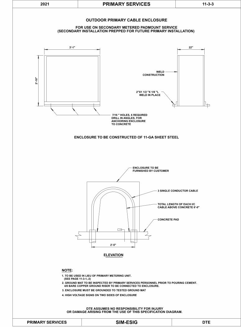
OUTDOOR PRIMARY CABLE ENCLOSURE
ELEVATION
ENCLOSURE TO BE CONSTRUCTED OF 11-GA SHEET STEEL
2'-
10"
3'-1" 22"
WELD
CONSTRUCTION
2"X1 1/2 "X 1/8 "L
WELD IN PLACE
7/16 " HOLES, 6 REQUIRED
DRILL IN ANGLES, FOR
ANCHORING ENCLOSURE
TO CONCRETE
ENCLOSURE TO BE
FURNISHED BY CUSTOMER
3 SINGLE CONDUCTOR CABLE
TOTAL LENGTH OF EACH I/C
CABLE ABOVE CONCRETE 6'-0"
CONCRETE PAD
2'-5"
NOTE:
PRIMARY SERVICES
1. TO BE USED IN LIEU OF PRIMARY METERING UNIT.
(SEE PAGE 11-3-1,-2)
2. GROUND MAT TO BE INSPECTED BY PRIMARY SERVICES PERSONNEL PRIOR TO POURING CEMENT.
4/0 BARE COPPER GROUND RISER TO BE CONNECTED TO ENCLOSURE.
2021
DTE ASSUMES NO RESPONSIBILITY FOR INJURY
OR DAMAGE ARISING FROM THE USE OF THIS SPECIFICATION DIAGRAM.
FOR USE ON SECONDARY METERED PADMOUNT SERVICE
(SECONDARY INSTALLATION PREPPED FOR FUTURE PRIMARY INSTALLATION)
3. ENCLOSURE MUST BE GROUNDED TO TESTED GROUND MAT
4. HIGH VOLTAGE SIGNS ON TWO SIDES OF ENCLOSURE

DTE
11-03-4
SIM-ESIG
PRIMARY SERVICE
B
PRIMARY SERVICES
DTE ASSUMES NO RESPONSIBILITY FOR INJURY
OR DAMAGE ARISING FROM THE USE OF THIS SPECIFICATION DIAGRAM.
GROUNDING SPECIFICATION
CUSTOMER OWNED TRANSFORMER INSTALLATION
A
TRANSFORMER PAD
D
12"
12"
12" 12"
TRANSFORMER
A
E
F
DA B
12"
C
12"
NOTES:
1. GROUNDING CONDUCTOR TO BE ENTIRELY CONTINUOUS.
2. CONDUCTOR TO FEED THROUGH ITEM E .
3. TRANSFORMER GROUND STRAP TO REMAIN.
4. GROUND MAT TO MEGGER 5 OHMS OR LESS.
5. PRIMARY SERVICE REPRESENTATIVE TO INSPECT FINISHED MAT PRIOR TO BURIAL.
BILL OF MATERIAL:
4/0 7-STRAND HARD DRAWN COPPER CONDUCTOR
5/8"x10' COPPER-CLAD GROUND ROD. GALVANIZED RODS UNACCEPTABLE
(QTY 3, 5/8"x4' COPPER-CLAD GROUND RODS COUPLED WITH
"DENMARK-5/8" CONNECTORS ACCEPTABLE AS SINGLE GROUND ROD)
ANDERSON CATALOG NO. GC-103-02 CONNECTOR
(CADWELD ACCEPTED AS ALTERNATIVE)
ANDERSON CATALOG NO. K-3 CONNECTOR
(4/0 BRONZE SPLIT BOLT ACCEPTABLE)
ANDERSON CATALOG NO. GTCS-41 TRANSFORMER TANK CONNECTOR
4/0 2-HOLE COPPER COMPRESSION LUG
(ANDERSON VHCL-4/0-12BN, OR BURNDY EQUIVALENT)
SET SCREW LUGS UNACCEPTABLE
A
B
C
D
E
F
X0
2021
DTESIM-ESIG
PRIMARY SERVICE
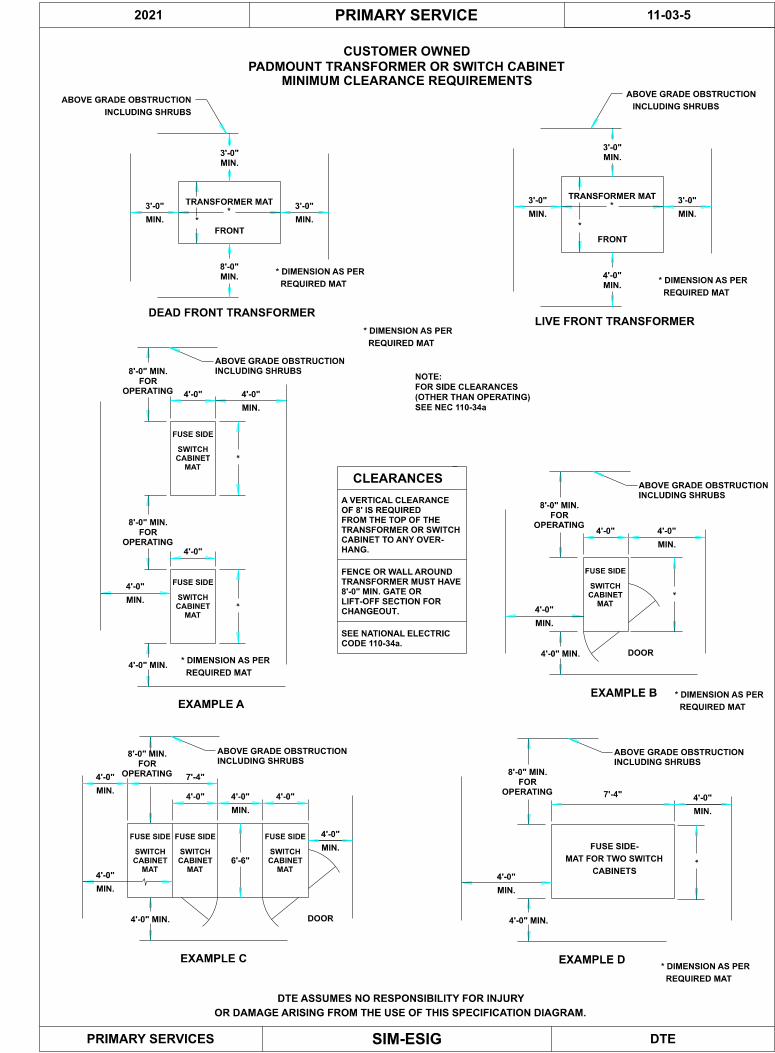
PADMOUNT TRANSFORMER OR SWITCH CABINET
MINIMUM CLEARANCE REQUIREMENTS
EXAMPLE C
4'-0"
8'-0" MIN.
FOR
OPERATING
4'-0" 4'-0"
MIN.
4'-0"
MIN.
4'-0"
MIN.
7'-4"
4'-0" MIN.
6'-6"
DOOR
4'-0"
MIN.
ABOVE GRADE OBSTRUCTION
INCLUDING SHRUBS
8'-0" MIN.
FOR
OPERATING 7'-4"
4'-0" MIN.
4'-0"
MIN.
ABOVE GRADE OBSTRUCTION
INCLUDING SHRUBS
EXAMPLE D
4'-0"
MIN.
FUSE SIDE-
MAT FOR TWO SWITCH
CABINETS
8'-0" MIN.
FOR
OPERATING
4'-0" MIN.
4'-0"
MIN.
ABOVE GRADE OBSTRUCTION
INCLUDING SHRUBS
EXAMPLE B
DOOR
4'-0"
MIN.
4'-0"
FUSE SIDE
SWITCH
CABINET
MAT
FUSE SIDE
SWITCH
CABINET
MAT
FUSE SIDE
SWITCH
CABINET
MAT
FUSE SIDE
SWITCH
CABINET
MAT
8'-0" MIN.
FOR
OPERATING
4'-0"
4'-0"
MIN.
4'-0" MIN.
ABOVE GRADE OBSTRUCTION
INCLUDING SHRUBS
FUSE SIDE
SWITCH
CABINET
MAT
EXAMPLE A
4'-0"
FUSE SIDE
SWITCH
CABINET
MAT
8'-0" MIN.
FOR
OPERATING
FENCE OR WALL AROUND
TRANSFORMER MUST HAVE
8'-0" MIN. GATE OR
LIFT-OFF SECTION FOR
CHANGEOUT.
A VERTICAL CLEARANCE
OF 8' IS REQUIRED
FROM THE TOP OF THE
TRANSFORMER OR SWITCH
CABINET TO ANY OVER-
HANG.
CLEARANCES
4'-0"
MIN.
3'-0"
MIN.
3'-0"
MIN.
3'-0"
MIN.
8'-0"
MIN.
DEAD FRONT TRANSFORMER
TRANSFORMER MAT
FRONT
*
*
* DIMENSION AS PER
REQUIRED MAT
ABOVE GRADE OBSTRUCTION
INCLUDING SHRUBS
3'-0"
MIN.
3'-0"
MIN.
3'-0"
MIN.
TRANSFORMER MAT
FRONT
*
*
* DIMENSION AS PER
REQUIRED MAT
ABOVE GRADE OBSTRUCTION
INCLUDING SHRUBS
4'-0"
MIN.
LIVE FRONT TRANSFORMER
PRIMARY SERVICES
DTE ASSUMES NO RESPONSIBILITY FOR INJURY
OR DAMAGE ARISING FROM THE USE OF THIS SPECIFICATION DIAGRAM.
11-03-5
SEE NATIONAL ELECTRIC
CODE 110-34a.
CUSTOMER OWNED
FOR SIDE CLEARANCES
(OTHER THAN OPERATING)
SEE NEC 110-34a
NOTE:
REQUIRED MAT
* DIMENSION AS PER
REQUIRED MAT
* DIMENSION AS PER
REQUIRED MAT
* DIMENSION AS PER
* DIMENSION AS PER
REQUIRED MAT
*
*
*
*
2021

2021 PRIMARY SERVICES 11-4-1
SIM-ESIG
LOCATION OF PRIMARY METERING EQUIPMENT
1. Meters
Meters should be located at the main incoming switchgear (which may be indoorsor outdoors). This location shall be clean and reasonably secure from damage, andnot subject to shock or vibration. Meters shall be readily accessible for reading,testing, and maintenance. A five (5) foot clearance should be maintained in front ofthe meters
When meters are located on balconies, mezzanines, or other floor levels, apermanent OSHA approved stairway shall be provided for access.
The meters shall be located as close as practical to the metering transformers, butnot to exceed 150 feet. If it is necessary to exceed 150 feet, approval by DTEPrimary Services will be necessary prior to the start of construction. DTE PrimaryServices will consult Meter Engineering for recommendations.
2. Meter Box
The meter box shall be supplied, installed & wired by the customer’scontractor. See 11-4-4, 11-4-5 & 11-4-6 for mounting and 11-4-10B & 11-4-12Bfor wiring. Manufacturer’s catalog numbers are listed in Sec. 11-4-1A.
3. Instrument Transformers
Primary current and voltage metering transformers are furnished by DTE andinstalled/wired by the customer’s contractor on primary metering installations.
4. Wire
DTE provides the wire (9-conductor #12) between the revenue metering instrumenttransformers and the meter box. DTE Also provides the potential transformerprimary wire. The customer’s contractor pulls and wires the metering per DTESpecifications, reference section 11-4-10B & 11-4-12B.
5. Outdoor Meter House
The meter(s) may be in an outdoor meter house. See DTE Primary ServicesRepresentative for location and DTE specifications.

2021 PRIMARY SERVICES 11-4-1A
SIM-ESIG
METER BOX MANUFACTURER’S CATALOG NUMBERS
Meter boxes should be obtained from local supply houses using the manufacturer’s catolognumbers listed below:
ZS3-20 METER BOX (3-PHASE, 4-WIRE) – WYE SYSTEMSExample: 480V, 8.3kV, 13.2 kV, 24 kV & 40 kV
Eaton 1007003CCH
Durham 1007003B
Square-D 1007003C
Midwest Electric Products 1007003B-MEP
Milbank UC6473-0-21
Meter Devices 602-3010A13-588
ZS3-20-5S METER BOX (3-PHASE, 3-WIRE) – DELTA SYSTEMExample: 4.8 kV
Eaton 1007361CCH
Durham 1007361B
Square-D 1007361C
Midwest Electric Products 1007361B-MEP
Milbank UC6472-0-21
Meter Devices 602-3010A8-589
AC-10 AUXILIARY CONTACT ENCLOSURE
Cutler-Hammer 1006630A-CH
Durham 1006630A
Square-D 1006630A-SQD
Midwest Electric Products 1006630A-MEP

2021 PRIMARY SERVICES 11-4-2
SIM-ESIG
FUSING OF DTE METERING VOLTAGE TRANSFORMERS
Fusing of DTE metering voltage transformers must be a consideration when designingthe revenue-metering cubicle.
To protect the integrity and safeguard personnel and equipment, fusing of DTE revenuemetering voltage transformers at Primary Customers is required if any one of thefollowing criteria is met:
1. All industrial substations
2. Services from transmission or subtransmission lines (includes 24 kV and above).
3. Where present or immediate future fault currents are:
7,000 amperes at 13.2 kV
10,000 amperes at 4.8 kV
4. All underground T-tap power lines.
All fuses shall be: G.E. Type EJ-1,15kv class, Size 2E.
The customer will furnish and install the metering cubicle, including fuse carriers andfuse. Fuses shall not be mounted directly on the voltage transformers. Three spacefuses are required per position.
Contact the DTE Primary Services Representative to determine whether the aboveconditions are present at a site-specific location.

SIM-ESIG
2021 11-04-3APRIMARY SERVICE
DTEPRIMARY SERVICES
OR DAMAGE ARISING FROM THE USE OF THIS SPECIFICATION DIAGRAM.
DTE ASSUMES NO RESPONSIBILITY FOR INJURY
LAYOUT 1
PRIMARY METERING BOX TYPE ZA-90
METER
PREFERRED LOCATION
FOR DTE METERING
1 1/2" RIGID CONDUIT
1'-6 "
METERBOARD 4'-6"X4'X3/4 " PLYWOOD
THIN WALL
2'x8 1/2 "
1'-2 1/2 "1'-2 1/2 "
METER CABINET (ZA-90) 1'-3"
SEE NOTE-2
OR #2 (MIN.) COPPER WIRE
1/8 "X 1" COPPER BUS
GROUND MAT
CONNECT TO DRIVEN
MAINTENANCE AND DEMAND METER SERVICING.
3. A 4'-6"X 4' CLEAR AREA MUST BE PROVIDED IN FRONT OF THE METERS FOR METER TESTING,
MAT IT MUST BE INSULATED FOR 600 VOLTS.
2. IF GROUND WIRE IS CARRIED THROUGH THE METER CONDUIT TO THE DRIVEN GROUND
OF THE S.I.M.
1. THIS IS THE PREFERRED ARRANGMENT. IF SPACE DOES NOT ALLOW, SEE PAGE 11-4-5
UNLESS OTHERWISE SPECIFIED BY PRIMARY SERVICES.
TRANSFORMERS. (1-1/2" DIAMETER RIGID CONDUIT
OPTIONAL LOCATIONS FOR CONDUIT FROM METERING
LEGEND:
MININUM SPACE CLEARANCES-SEE NOTE 5
PLYWOOD BOARD DIMENSION
4'-6" MIN.
(MINIMUM DIMENSIONS)
5'-0"
FLOOR
BUSHING
CONDUIT
3/4 "
2"
1 3/4 "
3"
8"
PIPE STRAP
12"
6'-6" MIN.
NOTES:
3/4" RIGID NIPPLE
CUSTOMER ACCESS BOX (AC-10)
CL
(FOR MAINTENANCE PURPOSES ONLY)
SINGLE LINE

SIM-ESIG
2021 11-04-3BPRIMARY SERVICE
DTEPRIMARY SERVICES
OR DAMAGE ARISING FROM THE USE OF THIS SPECIFICATION DIAGRAM.
DTE ASSUMES NO RESPONSIBILITY FOR INJURY
PRIMARY METERING BOX TYPE ZA-90
LAYOUT 2
METER
CABINET (ZA-90).
ON EACH SIDE OF THE METER CONNECTION
4. A ONE FOOT CLEARANCE MUST BE MAINTAINED
CHANGES.
TESTING, MAINTENANCE AND DEMAND TAPE
FRONT OF THE METER FOR METER
3. A 5' X 4' CLEAR AREA MUST BE PROVIDED IN
SEE NOTE-2
COPPER WIRE
OR No. 2 (MIN.)
1/8 "X 1" COPPER
PLYWOOD BOARD DIMENSION
3'-0" MIN.
SPACE CLEARANCE
5'-0" MIN.
23" MIN.
11"
1 3/4 "
(MINIMUM DIMENSIONS)
METERBOARD 3'X4'-6"X 3/4 " PLYWOOD
SERVICES, METER ENGINEERING).
OTHERWISE SPECIFIED BY MARKETING & METER
TRANSFORMERS. (1-1/2" DIA. RIGID STEEL UNLESS
OPTIONAL LOCATIONS FOR CONDUIT FROM METERING
THE ARRANGEMENT SHOWN ON PAGE 11-4-3.
TO BE USED WHEN SPACE LIMITATIONS DO NOT ALLOW
MASS", IT MUST BE INSULATED FOR 600 VOLTS.
THE METER CONDUIT TO THE ~DRIVEN GROUND
2. IF THE GROUND WIRE IS CARRIED THROUGH
LEGEND:
EQUIPMENT ONLY.
1. PLYWOOD METER BOARD IS FOR DTE
15" MIN.
16"
5'-0"
FLOOR
GROUND MASS
CONNECT TO DRIVEN
32 1/2 "
3"
8"
ENTRANCE
REAR
METER CABINET (ZA-90)
14 1/2 "14 1/2 "
16"
PIPE STRAP
12"
SINGLE LINE
NOTES:
CL
CUSTOMER ACCESS BOX (AC-10)
3/4" RIGID NIPPLE
-- Not to Scale --
(FOR MAINTENANCE PURPOSES ONLY)
SIM-ESIG
2021 11-04-3CPRIMARY SERVICE
DTEPRIMARY SERVICES
OR DAMAGE ARISING FROM THE USE OF THIS SPECIFICATION DIAGRAM.
DTE ASSUMES NO RESPONSIBILITY FOR INJURY
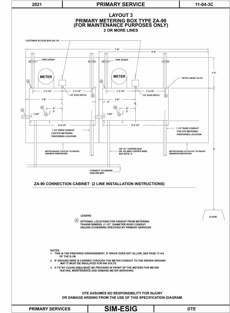
LAYOUT 3
PRIMARY METERING BOX TYPE ZA-90
FOR DTE METERING
1 1/2" RIGID CONDUIT
PREFERRED LOCATION
(MINIMUM DIMENSIONS)
METER BOARD 3'X4'X3/4" PLYWOOD
PIPE STRAP
LC
PREFERRED LOCATION
(MINIMUM DIMENSIONS)
METER BOARD 4'6"X4'X3/4" PLYWOOD
LC
METER CABINET (ZA-90)
LEGEND
TESTING, MAINTENANCE AND DEMAND METER SERVICING.
3. A 7'6"X4' CLEAR AREA MUST BE PROVIDED IN FRONT OF THE METERS FOR METER
MAT IT MUST BE INSULATED FOR 600 VOLTS.
2. IF GROUND WIRE IS CARRIED THROUGH THE METER CONDUIT TO THE DRIVEN GROUND
OF THE S.I.M.
1. THIS IS THE PREFERED ARRANGEMENT, IF SPACE DOES NOT ALLOW, SEE PAGE 11-4-6
NOTES:
UNLESS OTHERWISE SPECIFIED BY PRIMARY SERVICES
TRANSFORMERS. (1 1/2" DIAMETER RIGID CONDUIT
OPTIONAL LOCATIONS FOR C0NDUIT FROM METERING
ZA-90 CONNECTION CABINET (2 LINE INSTALLATION INSTRUCTIONS)
GROUND MAT
CONNECT TO DRIVEN
SEE NOTE -2
OR #2( MIN) COPPER WIRE
1/8" X1" COPPER BUS
FOR DTE METERING
1 1/2" RIGID CONDUIT
PIPE STRAP
FLOOR
2 OR MORE LINES
METER
1'-2 1/2"
2'-8 1/2"
8"
3"
1'-6"
4'-6"
7'-6"
METER
2'-8 1/2"
1'-6"
1'-2 1/2"
1 3/4"
1'-2 1/2"
8"
3"
4"
1 3/4"
5'
1'-2 1/2"
1'-3"
CUSTOMER ACCESS BOX (AC-10)
3/4" RIGID NIPPLE 3/4" RIGID NIPPLE
(FOR MAINTENANCE PURPOSES ONLY)

SIM-ESIG
2021 11-04-3DPRIMARY SERVICE
DTEPRIMARY SERVICES
OR DAMAGE ARISING FROM THE USE OF THIS SPECIFICATION DIAGRAM.
DTE ASSUMES NO RESPONSIBILITY FOR INJURY
PRIMARY METERING BOX TYPE ZA-90
LAYOUT 4
2 OR MORE LINES
5'-
0"
15" M
IN
3'-
0" M
IN
18"
(FU
TU
RE
LIN
E)
RE
AR
EN
TR
AN
CE
LE
GE
ND
OT
HE
RW
ISE
SP
EC
IFIE
D B
Y P
RIM
AR
Y S
ER
VIC
ES
PE
RS
ON
NE
L.
OP
TIO
NA
L L
OC
AT
ION
S F
OR
CO
ND
UIT
FR
OM
ME
TE
RIN
G T
RA
NS
FO
RM
ER
S. 1 1
/2 "
DIA
. U
NL
ES
S(MIN
IMU
M D
IME
NS
ION
S)
ME
TE
RB
OA
RD
3'X
4 1
/2'X
3/4
" P
LY
WO
OD
GR
OU
ND
MA
SS
CO
NN
EC
T T
O D
RIV
EN
1. IF
TH
E G
RO
UN
D W
IRE
IS
CA
RR
IED
TH
RO
UG
H T
HE
M
ET
ER
CO
ND
UIT
TO
TH
E "
DR
IVE
N G
RO
UN
D M
AS
S~
, IT
M
US
T B
E I
NS
UL
AT
ED
FO
R 6
00
VO
LT
S.
2.
A 4
FO
OT
CL
EA
R A
RE
A M
US
T B
E P
RO
VID
ED
IN
FR
ON
T O
F
T
HE
ME
TE
RS
FO
R M
ET
ER
TE
ST
ING
, M
AIN
TE
NA
NC
E A
ND
DE
MA
ND
T
AP
E C
HA
NG
ES
. T
HIS
AR
EA
MU
ST
EX
TE
ND
6" B
EY
ON
D E
AC
H S
IDE
O
F T
HE
MO
UN
TIN
G B
OA
RD
FO
R T
HE
ME
TE
RS
.
FL
OO
R
1/8
" X
1" C
OP
PE
R
OR
NO
.2 (
MIN
)
CO
PP
ER
WIR
E
SE
E N
OT
E 1
.
13" M
IN18"
32 1
/2"
PIP
E S
TR
AP
23" M
IN
14 1
/2"
14 1
/2"
11" 8
" 3"
3/4
" N
IPP
LE
(SA
ME
AS
LIN
E-1
)
ME
TE
R C
AB
INE
T (
ZA
90
)
LIN
E-2
ME
TE
R
NO
TE
S
ME
TE
R
LIN
E-1
1 3
/4"
16"
3/4
" R
IGID
NIP
PL
E
CU
ST
OM
ER
AC
CE
SS
BO
X (
AC
-10
)
(FOR MAINTENANCE PURPOSES ONLY)

SIM-ESIG
2021 11-04-4PRIMARY SERVICE
DTEPRIMARY SERVICES
OR DAMAGE ARISING FROM THE USE OF THIS SPECIFICATION DIAGRAM.
DTE ASSUMES NO RESPONSIBILITY FOR INJURY
INDOOR LAYOUT ARRANGEMENT
PRIMARY METERING BOX TYPE ZS3-20 or ZS3-20-5S
METERBOARD 4'X4'X3/4 " PLYWOOD
SUPPLIED AND INSTALLED BY CONTRACTOR.
METER BOX (ZS3-20 or ZS3-20-5S)
AND MAINTENANCE.
2. A 5' CLEAR AREA MUST BE PROVIDED IN FRONT OF THE METERS FOR METER TESTING
MAT IT MUST BE INSULATED FOR 600 VOLTS.
1. IF GROUND WIRE IS CARRIED THROUGH THE METER CONDUIT TO THE DRIVEN GROUND
UNLESS OTHERWISE SPECIFIED BY PRIMARY SERVICES.
TRANSFORMERS. 1-1/2" DIAMETER RIGID CONDUIT
OPTIONAL LOCATIONS FOR CONDUIT FROM METERING
LEGEND:
(MINIMUM DIMENSIONS)
NOTES:
(IF APPLICABLE)
CUSTOMER ACCESS BOX (AC-10)
FLOOR
6'-0"
48"
*
* ** 3/4" RIGID NIPPLE
8 1/4"1"
2 1/4"
1 1/2"
GROUND CONN.
-- NOT TO SCALE --
SINGLE LINE
(SEE NOTE 3 BELOW)
3. ONE AC-10 BOX IS REQUIRED FOR DTE COMMUNICATIONS AND IF APPLICABLE
ONE AC-10 BOX IS REQUIRED FOR CUSTOMER ACCESS. BOTH BOXES ARE
METER
DTE COMMUNICATIONS(AC-10)
4 1/2"
SUPPLIED AND INSTALLED BY CUSTOMER'S CONTRACTOR.
(SEE NOTE 3 BELOW)
CL
2'
4. GROUND CONNECTION - 3/8" x 1 1/2" BOLT, FLAT WASHER & LOCK WASHER (SILICON BRONZE)
(NOTE 4)

SIM-ESIG
2021 11-04-5PRIMARY SERVICE
DTEPRIMARY SERVICES
OR DAMAGE ARISING FROM THE USE OF THIS SPECIFICATION DIAGRAM.
DTE ASSUMES NO RESPONSIBILITY FOR INJURY
INDOOR LAYOUT ARRANGEMENT
PRIMARY METERING BOX TYPE ZS3-20 or ZS3-20-5S
METERBOARD 4'X6'X3/4 " PLYWOOD
SUPPLIED AND INSTALLED BY CONTRACTOR.
METER BOX (ZS3-20 or ZS3-20-5S)
AND MAINTENANCE.
2. A 5' CLEAR AREA MUST BE PROVIDED IN FRONT OF THE METERS FOR METER TESTING
MAT IT MUST BE INSULATED FOR 600 VOLTS.
1. IF GROUND WIRE IS CARRIED THROUGH THE METER CONDUIT TO THE DRIVEN GROUND
UNLESS OTHERWISE SPECIFIED BY PRIMARY SERVICES.
TRANSFORMERS. 1-1/2" DIAMETER RIGID CONDUIT
OPTIONAL LOCATIONS FOR CONDUIT FROM METERING
LEGEND:
(MINIMUM DIMENSIONS)
NOTES:
(SEE NOTE 3 BELOW)
(IF APPLICABLE)
FLOOR
6'-0"
48"
*
**
3/4" RIGID NIPPLE
8 1/4"1"
2 1/4"
TWO OR MORE LINES
1 1/2"
**
1 1/2"
6'
4'
-- NOT TO SCALE --
2 1/4"
3. TWO SEPARATE AC-10 BOXES ARE REQUIRED FOR CUSTOMER CONTACTS
TWO(2) ADDITIONAL AC-10 BOXES ARE REQUIRED
FOR DTE COMMUNICATIONS & AUXILARY POWER.
CUSTOMER ACCESS BOX (AC-10)
METER METER
AND AUXILARY
METER POWER(AC-10 BOX)
4. THIS TWO LINE ARRANGEMENT COULD BE USED OUTDOORS MOUNTED ON SWITCHGEAR.
DIMMENSIONS APPLY, SEE PRIMARY SERVICE REPRESENTATIVE PRIOR TO INSTALLATION
DTE COMMUNICATION
AND AUXILARY
METER POWER(AC-10 BOX)
DTE COMMUNICATION
+ SUPPLIED/INSTALLED BY DTE METER SERVICES.
4 1/2"GRD.CONN.
GRD.CONN.
4 1/2"
ALL BOXES ARE SUPPLIED/INSTALLED BY CUSTOMER'S CONTRACTOR.
(SEE NOTE 3 BELOW)
(SEE NOTE 3 BELOW)
FOR MOUNTING LOCATION.
CL
7" 7"
5. GROUND CONNECTION - 3/8" x 1 1/2" BOLT (SILICON BRONZE) , FLAT WASHER & LOCK WASHER (SILICON BRONZE)

SIM-ESIG
2021 11-04-6PRIMARY SERVICE
DTEPRIMARY SERVICES
OR DAMAGE ARISING FROM THE USE OF THIS SPECIFICATION DIAGRAM.
DTE ASSUMES NO RESPONSIBILITY FOR INJURY
COMBINATION FUSED LOADBREAK DISCONNECT SWITCH/METER UNIT
15"
50"
METER SECTIONFUSED LBS SECTION
UTILIZING A ZS3-20 METER BOX (4-Wire)
- SIDE VIEW -
CONRETE PAD
(Not to Scale)
1.5" Chase Nipple
CHASE NIPPLE.
GROUND CONDUCTOR, THEN ENTER THE METER BOX THROUGH THE 1.5"
LUG IS TO BE INSTALLED ON THE END OF THE 600 VOLT #2 COPPER
A GROUND CONNECTION POINT IN THE BOX. A ONE-HOLE COMPRESSION
BRONZE) WILL BE USED IN THE LOWER LEFT HAND CORNER TO PROVIDE
ETC.). A 1 1/2 - INCH BOLT, FLAT WASHERS & LOCK WASHERS (SILICON
WASHERS AND LOCK WASHERS (STAINLESS STEEL, SILICON BRONZE,
SWITCHGEAR WITH FOUR 1-INCH .25 x 20 RUSTPROOF BOLTS, FLAT
THE ZS3-20 (or ZS-20-5S) METER BOX WILL BE MOUNTED ON THE OUTDOOR
NOTES:
1.
AC-10
CUSTOMER'S CONTRACTOR.
BOTH BOXES SUPPLIED AND INSTALLED BY
ENTER THE ZS3-20 FROM BOTTOM PLATE.
THE CONNECTING CONDUIT (3/4" RIGID) MUST
CUSTOMER ACCESS OR DTE COMMUNICATIONS,
IF AN AC-10 IS TO BE INSTALLED FOR
PROVIDED IN FRONT OF THE METER.
A FIVE (5) FOOT CLEAR AREA MUST BE2.
3.
UTILIZING A ZS3-20-5S METER BOX (3-Wire)
OR
GROUNDCONNECTION
AC-10
(SEE NOTE 3 BELOW)
METER
OUTDOOR INSTALLATION LAYOUTFOR
LOCATION/INSTALLATION REQUIREMENTS.
SERVICE REPRESENTATIVE FOR METER BOX
FREE STANDING SWITCHGEAR. SEE PRIMARY
THIS LAYOUT CAN BE USED FOR OUTDOOR4.
3/4" RIGID NIPPLE

DTE
11-04-7
SIM-ESIG
PRIMARY SERVICE
DTE GENERAL SPECIFICATIONS FOR METERING CUBICLE
USED WITH METAL-CLAD SWITCHGEAR
(FOR DIMENSIONS, SEE PAGES 11-4-14 through 11-4-17)
AA
ELEVATION (SIDEVIEW)
13.2 kV
PLAN VIEW A-A
13.2 & 4.8 kV
SERVICE CABLES
AND CONDUIT
3-POTENTIAL TRANSFORMERS FOR 13.2 kV
2-POTENTIAL TRANSFORMERS FOR 4.8 kV
PROVIDE MOUNTING HOLES FOR 3 TRANSFORMERS
DOOR EQUIPPED
WITH 3 POINT
LATCH AND
PROVISION FOR
D.E.CO. PADLOCK
RIGID METAL SUPPORT FOR
BOTH 13.2 kV & 4.8 kV ARRANGEMENTS
(2- 3/8" BOLTS PER TRANSFORMER REQUIRED)
POTENTIAL TRANSFORMERS
PT LEADS FURNISHED BT DTE
RIGID METAL SUPPORT FOR
BOTH 13.2 kV & 4.8 kV ARRANGEMENTS
(4- 3/8" BOLTS PER TRANSFORMER REQUIRED)
CURRENT TRANSFORMERS
1" EMT RACEWAY FOR SECONDARY WIRES
TO BUS
PRIMARY SERVICES
6" MIN. PHASE TO PHASE
1 1/2" RIGID STEEL CONDUIT TO DTE METERS
SUGGESTED EQUIPMENT ARRANGEMENT FOR 13.2 kV SERVICE-95 KV BIL.
MANUFACTURER TO PROVIDE MOUNTING AND BUS CONNECTIONS FOR
DTE INSTRUMENT TRANSFORMERS IN CUBICLE. DTE WILL SPECIFY
THE TYPE AND NUMBER OF TRANSFORMERS REQUIRED.
18" MIN.
2021
DTE ASSUMES NO RESPONSIBILITY FOR INJURY
OR DAMAGE ARISING FROM THE USE OF THIS SPECIFICATION DIAGRAM.
3-1/C-15 kV-POWER CABLE

SIM-ESIG
2021 11-04-8PRIMARY SERVICES
DTEPRIMARY SERVICES
OR DAMAGE ARISING FROM THE USE OF THIS SPECIFICATION DIAGRAM.
DTE ASSUMES NO RESPONSIBILITY FOR INJURY
OUTDOOR METER UNIT
13.2kV OR 4.8kV
- MUST MAINTAIN 29" CONDUIT SPACING.
UNIT IS INTERCHANGEABLE WITH TYPE PM-123 UNIT
TOP VIEW
FRONT DOOR
THIS SIDE
PT GROUND CONNECTION
REAR DOOR
8.
7.
6.
5.
SEAL CONDUIT WITH DUCT SEAL.
POTENTIAL TRANSFORMER SHELF IS REMOVABLE
CABLE AND CONNECT TO UNIT GROUND MASS.
DETERMINED ON JOB SITE - SEE PRIMARY SERVICES REPRESENTATIVE.
POTENTIAL AND CURRENT TRANSFORMERS PROVIDED BY DTE.
SEE PAGES 11-4-10, 11-4-12 & 11-4-10C FOR WIRING INSTRUCTIONS.
KIT REQUIRED FOR 4.8kV USE.
4.
3.
2.
1.
NOTES:
(SEE NOTE 5)
TRANSFORMERS
PROVISIONS FOR 3
TRANSFORMERS
PROVISIONS FOR 3
DOOR
REAR
50"
SIDE VIEWFRONT VIEW
INSULATORS
PORCELAIN OR CYCLOALIPHATIC
15KV, 95KV B.I.L.
29"LINE SIDE CONDUIT 4" MINIMUM
(SEE NOTES #5&6)
48"
68"
DOOR
FRONT
1 1/2" RIGID STEEL CONDUIT TO DTE METERS. LOCATION TO BE
INCLUDE #2 COPPER WIRE (600V INSULATION) IN SAME CONDUIT WITH METER
DTE CURRENT
DTE POTENTIAL
LOAD SIDE CONDUIT 4"
INNER SCREEN
BARRIER
CT
PT
INNER SCREEN
BARRIER9.
SECONDARY METER WIRE PROVIDED BY DTE.
PADLOCKABLE
HANDLE 3/8" SHACKLE
PADLOCKABLE
HANDLE 3/8" SHACKLE
DOORS REQUIRE 3-POINT LATCHING10.
(SEE NOTE 10)
(SEE NOTE 10)
LOUVERED
VENTS
VENTS
LOUVERED
LOUVERED
VENTS
VENTS
LOUVERED
LOUVERED VENTS NEED TO BE RAINPROOF.11.
(SEE NOTE 11)
PT SHELF
18"
COPPER BUS

SIM-ESIG
2021 11-04-9PRIMARY SERVICES
DTEPRIMARY SERVICES
OR DAMAGE ARISING FROM THE USE OF THIS SPECIFICATION DIAGRAM.
DTE ASSUMES NO RESPONSIBILITY FOR INJURY
INSTALLATIONS INSTRUCTIONS
13.2KV OLD TYPE KU OUTDOOR METER UNIT (MAINTENANCE ONLY)
#2-600V
COMPRESSION LUGS.
EXCEPT KU UNIT, PRIMARY CABLE, TERMINATIONS AND
ALL EQUIPMENT FURNISHED BY DTE
SEE ALUMINUM DETAIL BELOW.
NUTS UNTIL BELLEVILLE SPRING WASHER FLATTENS.
FOR ALUMINUM LUGS, COAT WITH NO-OX-ID, TIGHTEN
(SEE NOTE 5)
WASHER 1 1/4" DIA.
1/2" BELLEVILLE SPRING
COPPER LUGS(ENLARGED VIEW)
C-C (OF B-B)NO CUTTING OR DRILLING OF METER UNIT PERMITTED
SEE NOTE 1, PAGE 11-4-28
6"6"
B
B-B (OF C-C)
DUCT-SEAL COMPOUND
SEAL ALL CONDUIT WITH
BCA
P.T. WIRE
15KV #6 AWG
VIEWS ABOVE
SEE ENLARGED
LOCKWASHER & NUT
PLATED BOLT,
3/8"-16 X 1"
BARRIER
PLEXIGLASS
C
C
A
(ENLARGED VIEW)
ALUMINUM LUGSON 1 3/4" CENTERS
AS SHOWN 9/16" HOLES
SUIT CABLE BEND LUG
LUG SIZE & TYPE TO
2 BOLT COMPRESSIONCRIMP LUG
1/2" FLAT WASHER
STEEL BOLTS & NUTS
1/2"-13 X 1 1/2" GALV.
ON 1 3/4" CENTERS
AS SHOWN 9/16" HOLES
SUIT CABLE BEND LUG
LUG SIZE & TYPE TO
2 BOLT COMPRESSION
CRIMP LUG
1/2" FLAT WASHER
1/2" LOCKWASHERS
STEEL BOLTS & NUTS
1/2"-13 X 1 1/2" GALV.
PLAN VIEW AT A-A (OF B-B)
SEE NOTE 1 PAGE 1-4-28
(PHASE)
(PHASE)
B
A
C
FRONT DOOR
TO GRD MASS
#2 BARE COPPER
(PHASE)
TO PAD (2 LOCATIONS)
ANCHOR HOUSING
& FLAT WASHER
3/8"-16 X 1" BOLT, LOCKWASHER
6.
5.
WASHERS PROVIDED.
CLOSE THE TWO ANCHOR HOLES WITH THE SQUARE
BE FASTENED TO THE RACK AT THE FOUR CORNERS.
THE PRIMARY AND METER CONDUIT OPENINGS. UNIT MUST
FOR RACK MOUNTING, PLATES ARE FURNISHED TO COVER
BE CUT, BUT SEE NOTE 1, PAGE 11-4-12.
STRIP 15 FOOT OF JACKET OFF METER CABLE. WIRES MAY
SEE PAGE 11-4-28 FOR WIRING INSTRUCTIONS.
BETWEEN HOUSING AND PAD.
2" BEYOND ALL SIDES. A COMPLETE SEAL MUST BE FORMED
WATERPROOF ENTIRE PAD UNDER HOUSING. EXTEND COMPOUND
3.
NOTES:
1.
2.
4.
A
B

SIM-ESIG
2021 11-04-10APRIMARY SERVICE
DTEPRIMARY SERVICES
OR DAMAGE ARISING FROM THE USE OF THIS SPECIFICATION DIAGRAM.
DTE ASSUMES NO RESPONSIBILITY FOR INJURY
(2 CURRENT TRANSFORMERS)
4.8kV METER UNITWIRING INSTRUCTIONS
BLOCK
FUSE
ILLUSTRATION #1
FUTURE 13.2 KV
NOTE:
WIRE 600V INSULATION
HYPRESS OR SADDLE LUG
#2 STRANDED GROUND
CABINET
IN BOTTOM OF
LEAVE 36" BUNDLED
1. DTE METER WIRE TO BE TERMINATED WITH LOOP OR RING
TYPE STAKE ON LUGS. FORK TYPE STAKE ON LUGS SHALL
NOT BE PREMITTED
2. THE STAKE ON LUGS SHALL BE INSTALLED BETWEEN THE
TWO FLAT WASHERS ON THE TERMINAL POST.
SEE INSET ILLUSTRATION #1
*REMOVE CT JUMPERS FROM SECONDARY TERMINALS
AFTER WIRING TO TEST SWITCH AND METERS
HAVE BEEN APPROVED BY PRIMARY SERVICES
**
SEE NOTE 5
LOOPED & NOT CUT
ZX
CTCT
LOAD
LINE
LOAD
LINE
WHITE/BLACK
GREEN
RED/BLACK
BLACK
BLACK
RED/BLACK
GREEN
WH
ITE
/BL
AC
K
WHITE/BLACK
WH
ITE
/BL
AC
K
REFER TO DRAWING #6
FOR METER CONNECTION
CABINET WIRING INSTRUCTIONS
VT
BLUE
LOOPED & NOT CUT
WHITE
BLUE
WHITE
ORANGE
7. THE TOTAL LENGTH OF THE DTE 9 CONDUCTOR METER CABLE SHALL NOT EXCEED 150 FEET
6. FOR FUTURE 3RD VT (13.2 kV CONVERSION ETC.)
5. FOR FUTURE 3RD CT.
SEE NOTE 6 ORANGE
ALTERNATIVES MUST BE APPROVED, PRIOR TO INSTALLATION, BY PRIMARY SERVICES.
4. A #2 600 VOLT INSULATED GROUND CONDUCTOR (FURNISHED BY CUSTOMER) SHALL BE PULLED IN WITH THE 9 CONDUCTOR METER CABLE.
3. VT AND CT WIRES SHALL BE CONTINUOUS TO THE POINT OF CONNECTION. CUTTING OR SPLICING TO THAT POINT SHALL NOT BE PERMITTED.
2. VT WIRES RED AND BLUE SHALL BE LONG ENOUGH TO REACH EITHER VT TERMINAL.
1. CT WIRES BLACK AND GREEN SHALL BE LONG ENOUGH TO REACH EITHER CT TERMINAL.
NOTES:
RED
WHITEREDRED
Y
VT
METER CONNECTION CABINET (ZA-90)
PHASE ROTATION A-B-C
OR
AN
GE
RE
D/B
LA
CK
RE
D
WH
ITE
BL
UE
WH
ITE
/BL
AC
K
GR
EE
N
BL
AC
K
(FOR MAINTENANCE OF EXISTING INSTALLATIONS ONLY)
oA
oB
oC

SIM-ESIG
2021 11-04-10BPRIMARY SERVICE
DTEPRIMARY SERVICES
OR DAMAGE ARISING FROM THE USE OF THIS SPECIFICATION DIAGRAM.
DTE ASSUMES NO RESPONSIBILITY FOR INJURY
(2 CURRENT TRANSFORMERS)
4.8KV DELTA SYSTEMWIRING INSTRUCTIONS
NOTE:
1. DTE METER WIRE TO BE TERMINATED WITH LOOP OR RING
TYPE STAKE ON LUGS. FORK TYPE STAKE ON LUGS SHALL
NOT BE PREMITTED
2. THE STAKE ON LUGS SHALL BE INSTALLED BETWEEN THE
TWO FLAT WASHERS ON THE TERMINAL POST.
SEE INSET ILLUSTRATION #1
*REMOVE CT JUMPERS FROM SECONDARY TERMINALS
AFTER WIRING TO TEST SWITCH AND METERS
HAVE BEEN APPROVED BY PRIMARY SERVICES
*
SEE NOTE 5
LOOPED & NOT CUT
o
ZX
o
CTCT
LOAD
LINE
LOAD
LINE
BLACKGREEN
REFER TO DRAWING #6
FOR METER CONNECTION
CABINET WIRING INSTRUCTIONS
VT
o
7. THE TOTAL LENGTH OF THE DTE 9 CONDUCTOR METER CABLE SHALL NOT EXCEED 150 FEET
6. FOR FUTURE 3RD VT (13.2 kV CONVERSION ETC.)
5. FOR FUTURE 3RD CT.
ALTERNATIVES MUST BE APPROVED, PRIOR TO INSTALLATION, BY PRIMARY SERVICES.
4. A #2 CU 600 VOLT INSULATED GROUND CONDUCTOR (FURNISHED BY CUSTOMER) SHALL BE PULLED IN WITH THE 9 CONDUCTOR METER CABLE.
3. VT AND CT WIRES SHALL BE CONTINUOUS TO THE POINT OF CONNECTION. CUTTING OR SPLICING TO THAT POINT SHALL NOT BE PERMITTED.
2. VT WIRES RED AND BLUE SHALL BE LONG ENOUGH TO REACH EITHER VT TERMINAL.
1. CT WIRES BLACK AND GREEN SHALL BE LONG ENOUGH TO REACH EITHER CT TERMINAL.
NOTES:
Y
VT
METER CONNECTION CABINET (ZS3-20-5S)
ILLUSTRATION #1
X Z Y
XP ZP
+ +
RE
D
BL
UE
BL
AC
K
WH
ITE
WH
ITE
/BL
AC
K
GR
EE
N
WH
ITE
C
B
A
BLUE
LOOPED & NOT CUT
WHITE
BLUE
WHITE
ORANGESEE NOTE 6 ORANGE
RED
WHITEREDRED
WHITE/BLACK
GREEN
RED/BLACK
BLACKRED/BLACK
WH
ITE
/BL
AC
K
WHITE/BLACK
WH
ITE
/BL
AC
K
*

SIM-ESIG
2021 11-04-11PRIMARY SERVICE
DTEPRIMARY SERVICES
OR DAMAGE ARISING FROM THE USE OF THIS SPECIFICATION DIAGRAM.
DTE ASSUMES NO RESPONSIBILITY FOR INJURY
4.8kV METER UNIT
(3 CURRENT TRANSFORMER)
WIRING INSTRUCTIONS
(FOR MAINTENANCE PURPOSES ONLY, NOT FOR NEW INSTALLATIONS)
NOT CUT
*
LOOPED &
ZX
CTCTCT
GREEN
RED/BLACK
BLACK
BLACKRED/BLACKGREEN
WH
ITE
/BL
AC
K
WH
ITE
/BL
AC
K
WH
ITE
/BL
AC
K
6. THE TOTAL LENGTH OF THE DTE 9 CONDUCTOR METER CABLE SHALL NOT EXCEED 150 FEET
REMOVE CT JUMPERS FROM SECONDARY TERMINALS
AFTER WIRING TO TEST SWITCH AND METERS
HAVE BEEN APPROVED BY PRIMARY SERVICES
REFER TO DRAWING #4
FOR METER CONNECTION
CABINET WIRING INSTRUCTIONS
5. FOR FUTURE 3RD VT (13.2 kV CONVERSION ETC.)
SEE NOTE 5
ALTERNATIVES MUST BE APPROVED, PRIOR TO INSTALLATION, BY PRIMARY SERVICES.
4. A #2 600 VOLT INSULATED GROUND CONDUCTOR (FURNISHED BY CUSTOMER) SHALL BE PULLED IN WITH THE 9 CONDUCTOR METER CABLE.
3. VT AND CT WIRES SHALL BE CONTINUOUS TO THE POINT OF CONNECTION. CUTTING OR SPLICING TO THAT POINT SHALL NOT BE PERMITTED.
2. VT WIRES RED AND BLUE SHALL BE LONG ENOUGH TO REACH EITHER VT TERMINAL.
1. CT WIRES BLACK AND GREEN SHALL BE LONG ENOUGH TO REACH EITHER CT TERMINAL.
NOTES:
Y
VTVT
LOAD
LINE
ILLUSTRATION #1
1. DTE METER WIRE TO BE TERMINATED WITH LOOP OR RING
TYPE STAKE ON LUGS. FORK TYPE STAKE ON LUGS SHALL
NOT BE PREMITTED
2. THE STAKE ON LUGS SHALL BE INSTALLED BETWEEN THE
TWO FLAT WASHERS ON THE TERMINAL POST.
SEE INSET ILLUSTRATION #1
NOTE:
METER CONNECTION CABINET (ZA-90)
HYPRESS OR SADDLE LUG
WIRE 600V INSULATION
#2 STRANDED GROUND
BLOCK
FUSE
LINE
WHITE/BLACK
*
LOAD
oA
oB
oC
FUTURE 13.2 KV
CABINET
IN BOTTOM OF
LEAVE 36" BUNDLED
OR
AN
GE
RE
D/B
LA
CK
PHASE ROTATION A-B-C
RE
D
WH
ITE
BL
UE
GR
EE
N
BL
AC
K
WH
ITE
/BL
AC
K
BLUE
LOOPED & NOT CUT
WHITE
BLUE
WHITE
ORANGEORANGE
RED
WHITEREDRED
* *
SIM-ESIG
2021 11-04-12APRIMARY SERVICE
DTEPRIMARY SERVICES
OR DAMAGE ARISING FROM THE USE OF THIS SPECIFICATION DIAGRAM.
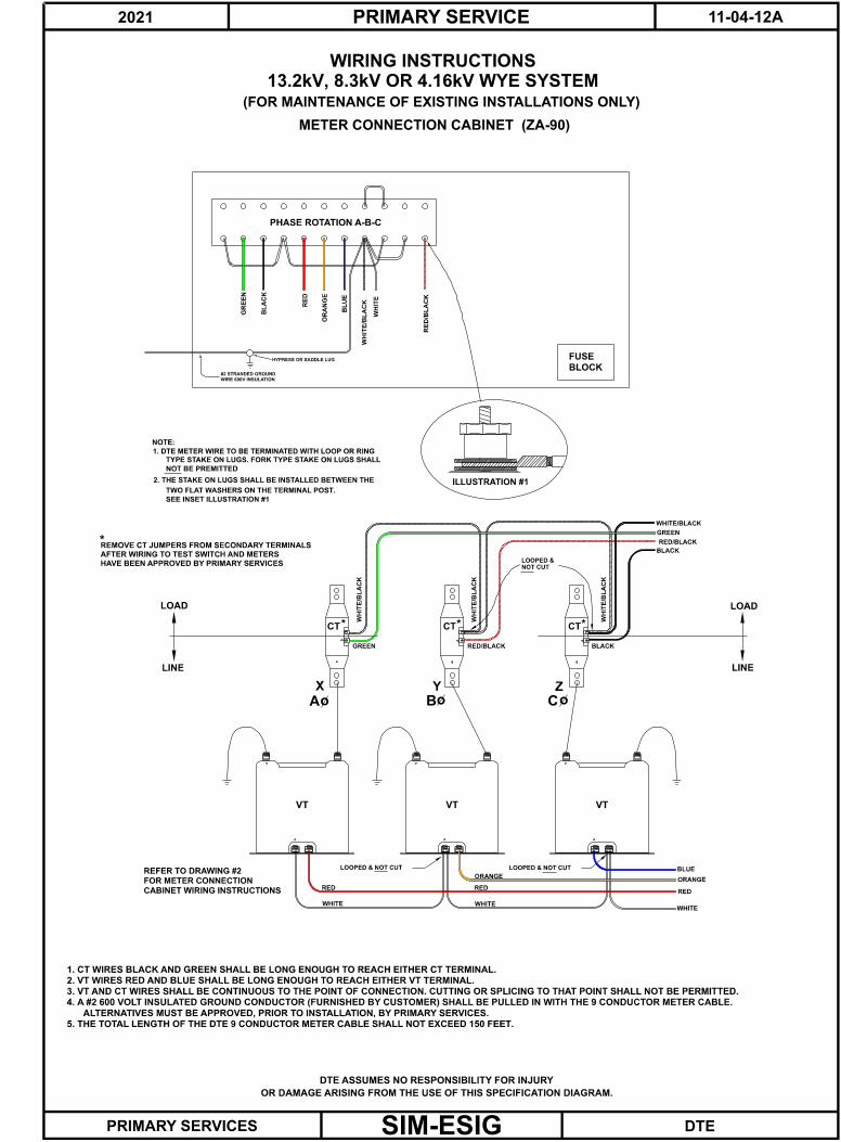
DTE ASSUMES NO RESPONSIBILITY FOR INJURY
13.2kV, 8.3kV OR 4.16kV WYE SYSTEM
WIRING INSTRUCTIONS
WH
ITE
RE
D
OR
AN
GE
BL
UE
WH
ITE
/BL
AC
K
GR
EE
N
RE
D/B
LA
CK
BL
AC
K
ILLUSTRATION #1
1. DTE METER WIRE TO BE TERMINATED WITH LOOP OR RING
TYPE STAKE ON LUGS. FORK TYPE STAKE ON LUGS SHALL
NOT BE PREMITTED
2. THE STAKE ON LUGS SHALL BE INSTALLED BETWEEN THE
TWO FLAT WASHERS ON THE TERMINAL POST.
SEE INSET ILLUSTRATION #1
NOTE:
PHASE ROTATION A-B-C
METER CONNECTION CABINET (ZA-90)
HYPRESS OR SADDLE LUG
WIRE 600V INSULATION
#2 STRANDED GROUND
BLOCK
FUSE
NOT CUT
5. THE TOTAL LENGTH OF THE DTE 9 CONDUCTOR METER CABLE SHALL NOT EXCEED 150 FEET.
*
CABINET WIRING INSTRUCTIONS
FOR METER CONNECTION
REFER TO DRAWING #2
HAVE BEEN APPROVED BY PRIMARY SERVICES
AFTER WIRING TO TEST SWITCH AND METERS
REMOVE CT JUMPERS FROM SECONDARY TERMINALS*
ALTERNATIVES MUST BE APPROVED, PRIOR TO INSTALLATION, BY PRIMARY SERVICES.
4. A #2 600 VOLT INSULATED GROUND CONDUCTOR (FURNISHED BY CUSTOMER) SHALL BE PULLED IN WITH THE 9 CONDUCTOR METER CABLE.
3. VT AND CT WIRES SHALL BE CONTINUOUS TO THE POINT OF CONNECTION. CUTTING OR SPLICING TO THAT POINT SHALL NOT BE PERMITTED.
2. VT WIRES RED AND BLUE SHALL BE LONG ENOUGH TO REACH EITHER VT TERMINAL.
1. CT WIRES BLACK AND GREEN SHALL BE LONG ENOUGH TO REACH EITHER CT TERMINAL.
LOOPED &
LOOPED & NOT CUTLOOPED & NOT CUT
ZYX
CTCTCT
VTVTVT
LOAD
LINE
LOAD
LINE
WHITE/BLACK
GREEN
RED/BLACK
BLACK
BLACKRED/BLACKGREEN
WH
ITE
/BL
AC
K
WH
ITE
/BL
AC
K
WH
ITE
/BL
AC
K
ORANGE
REDRED
WHITEWHITE
BLUE
ORANGE
RED
WHITE
(FOR MAINTENANCE OF EXISTING INSTALLATIONS ONLY)
oA oB oC
* *

SIM-ESIG
2021 11-04-12BPRIMARY SERVICE
DTEPRIMARY SERVICES
OR DAMAGE ARISING FROM THE USE OF THIS SPECIFICATION DIAGRAM.
DTE ASSUMES NO RESPONSIBILITY FOR INJURY
13.2kV, 8.3kV OR 4.16kV WYE SYSTEM
WIRING INSTRUCTIONS
ILLUSTRATION #1
1. DTE METER WIRE TO BE TERMINATED WITH LOOP OR RING
TYPE STAKE ON LUGS. FORK TYPE STAKE ON LUGS SHALL
NOT BE PREMITTED
2. THE STAKE ON LUGS SHALL BE INSTALLED BETWEEN THE
TWO FLAT WASHERS ON THE TERMINAL POST.
SEE INSET ILLUSTRATION #1
NOTE:
METER CONNECTION BOX - TYPE ZS3-20 (4-Wire)
NOT CUT
5. THE TOTAL LENGTH OF THE DTE 9 CONDUCTOR METER CABLE SHALL NOT EXCEED 150 FEET.
*
CABINET WIRING INSTRUCTIONS
FOR METER CONNECTION
REFER TO DRAWING #2
HAVE BEEN APPROVED BY PRIMARY SERVICES
AFTER WIRING TO TEST SWITCH AND METERS
REMOVE CT JUMPERS FROM SECONDARY TERMINALS*
ALTERNATIVES MUST BE APPROVED, PRIOR TO INSTALLATION, BY PRIMARY SERVICES.
4. A #2 CU 600 VOLT INSULATED GROUND CONDUCTOR (FURNISHED BY CUSTOMER) SHALL BE PULLED IN WITH THE 9 CONDUCTOR METER CABLE.
3. VT AND CT WIRES SHALL BE CONTINUOUS TO THE POINT OF CONNECTION. CUTTING OR SPLICING TO THAT POINT SHALL NOT BE PERMITTED.
2. VT WIRES RED AND BLUE SHALL BE LONG ENOUGH TO REACH EITHER VT TERMINAL.
1. CT WIRES BLACK AND GREEN SHALL BE LONG ENOUGH TO REACH EITHER CT TERMINAL.
LOOPED &
ZYX
CTCTCT
VTVTVT
LOAD
LINE
LOAD
LINE
WHITE/BLACK
RED/BLACK
BLACK
BLACKRED/BLACKGREEN
WH
ITE
/BL
AC
K
WH
ITE
/BL
AC
K
WH
ITE
/BL
AC
K
X Y Z N
X Y Z
+ + +
RE
D
OR
AN
GE
BL
UE
RE
D/B
LA
CK
BL
AC
K
WH
ITE
WH
ITE
/BL
AC
K
GR
EE
N
WH
ITE
oA oB oC
LOOPED & NOT CUTLOOPED & NOT CUT
ORANGE
REDRED
WHITEWHITE
BLUE
ORANGE
RED
WHITE
GREEN
* *

SIM-ESIG
2021 11-04-13PRIMARY SERVICE
DTEPRIMARY SERVICES
OR DAMAGE ARISING FROM THE USE OF THIS SPECIFICATION DIAGRAM.
DTE ASSUMES NO RESPONSIBILITY FOR INJURY
INSTALLATION INSTRUCTIONS
COMBINATION METERING AND SWITCH UNIT
13.2kV OR 8.3kV OUTDOOR N
OT
ES
:
SW
ITC
H C
OM
PA
RT
ME
NT
FU
SE
D L
OA
D B
RE
AK
VIE
W
TO
P
BO
TH
BA
R T
AP
LU
GS
PO
T W
IRE
PL
AC
ED
UN
DE
R
SIL
ICO
NE
BR
ON
ZE
BO
LT
S &
NU
TS
1/2
"-1
3 X
1 1
/2"
1/2
" L
OC
KW
AS
HE
RS
CO
PP
ER
LU
GS
ON
1 3
/4" C
EN
TE
RS
SU
IT C
AB
LE
9/1
6" H
OL
ES
LU
G S
IZE
& T
YP
E T
O
2 B
OL
T C
OM
PR
ES
SIO
N
1/2
" F
LA
T W
AS
HE
R
CR
IMP
LU
G
AL
UM
INU
M L
UG
S
(SE
E N
OT
E 4
)
WA
SH
ER
1 1
/4" D
IA.
1/2
" B
EL
LE
VIL
LE
SP
RIN
G
ST
EE
L B
OL
TS
& N
UT
S
1/2
"-1
3 X
1 1
/2" G
AL
V.
ON
1 3
/4" C
EN
TE
RS
SU
IT C
AB
LE
9/1
6" H
OL
ES
LU
G S
IZE
& T
YP
E T
O
2 B
OL
T C
OM
PR
ES
SIO
N
1/2
" F
LA
T W
AS
HE
R
CR
IMP
LU
G
FL
AT
WA
SH
ER
S T
O M
OU
NT
CT
'S A
ND
PT
'S.
US
E 3
/8"-1
6 X
1" P
LA
TE
D B
OL
TS
, L
OC
KW
AS
HE
RS
, A
ND
3.
22
VT
VT
VT
S.K 2019
AC
BA
AC
BC
-C O
F A
-AA
-AB
-B O
F A
-AA
VT
VT
VTC
TA
CT
CT
SE
E P
AG
E 1
1-4
-28 F
OR
WIR
ING
IN
ST
RU
CT
ION
S.
2.
1.
UN
TIL
BE
LL
EV
ILL
E S
PR
ING
WA
SH
ER
FL
AT
TE
NS
.
A W
IRE
BR
US
H,
TH
EN
CO
AT
WIT
H N
O-O
X-I
D.
TIG
HT
EN
NU
TS
FO
R A
LU
MIN
UM
LU
GS
, C
LE
AN
AL
L C
ON
TA
CT
SU
RF
AC
ES
WIT
H
oB
oC
o
Ao
Bo
Co
Ao
Bo
Co
S.KASSEM (2019 ULTIMATE REV)
B.BATTLE (2006 REV)
B.BATTLE (2006 REV)
S.KASSEM (2019 ULTIMATE REV)

SIM-ESIG
2021 11-04-14PRIMARY SERVICE
DTEPRIMARY SERVICES
OR DAMAGE ARISING FROM THE USE OF THIS SPECIFICATION DIAGRAM.
DTE ASSUMES NO RESPONSIBILITY FOR INJURY
5 TO 800 AMPERES - 4.8KV
OUTLINE OF 8.7KV METERING TRANSFORMERS
4 3/4"
7/16" SLOTS
5/16" HOLES
7 7/8"
7 1/8"
4 1/4"
(2 REQUIRED)
JKM-4 CURRENT TRANSFORMERS1/8"
5 3/4"
"A"
3 7/8"
"B"
2 7/8"
3/4"
16"
15" 1/2"
1"
9/16" DIA. HOLE
9/16" SLOTS
5 1/8"
2"
2"
1 1/2"
3/8"
1/4"
3/16"
500-800
200-400
5-150
"A" "B"
IMPORTANT
NOTE AMPERE RATING
5"
1 21/32"
27/32"
40/1 RATIO (2 REQUIRED)
JVM-4 POTENTIAL TRANSFORMERS (UNFUSED)
3/4"
RATING
AMPERE
7/16" DIA. HOLES
2"
7/16" SLOTS
3/4"
NOT TAPED
PRIMARY TERMINALS
3/16"
21/32"
12 1/4"8"
9 1/2"
13 3/4"
8 15/16"
9 11/16"
8 3/16"
2 1/8"
BE HINGED, BOLTED AND PADLOCKED.
IN SWITCHGEAR SUPERSTRUCTURE. DOOR TO
POTENTIAL TRANSFORMERS MAY BE LOCATED
ALTERNATE LOCATION:
LC
CL
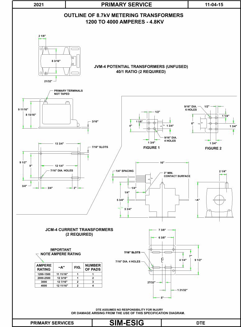
SIM-ESIG
2021 11-04-15PRIMARY SERVICE
DTEPRIMARY SERVICES
OR DAMAGE ARISING FROM THE USE OF THIS SPECIFICATION DIAGRAM.
DTE ASSUMES NO RESPONSIBILITY FOR INJURY
OUTLINE OF 8.7kV METERING TRANSFORMERS
1200 TO 4000 AMPERES - 4.8KV
1
2
3
42
2
1
1
(2 REQUIRED)
JCM-4 CURRENT TRANSFORMERS
FIGURE 2FIGURE 1
4 HOLES
9/16" DIA.
1/2"
4" 1 3/4"
1 1/8"
1 3/4" 1 3/4"
1 1/4"
6"
6 HOLES
9/16" DIA. 1/2"
1 3/4"
IMPORTANT
NOTE AMPERE RATING
OF PADS
NUMBER
12 11/16"
12 7/16"
12 3/16"
FIG.
11 11/16"
4000
3000
2000-2500
1200-1500
~A"
2 1/4"
16"
5 3/4"
5 3/4"
1/4"
CONTACT SURFACE
3" MIN.1/4" SPACING
1/4"
7/16" DIA. 4 HOLES
7/16" SLOTS7/16" SLOTS
7"
6 3/8"
7 3/8"
9 1/2"
5"
1 21/32"
27/32"
4 1/4"
40/1 RATIO (2 REQUIRED)
JVM-4 POTENTIAL TRANSFORMERS (UNFUSED)
3/4"
~A"RATING
AMPERE
7/16" DIA. HOLES
2"
7/16" SLOTS
3/4"
NOT TAPED
PRIMARY TERMINALS
3/16"
21/32"
12 1/4"8"
9 1/2"
13 3/4"
8 15/16"
9 11/16"
8 3/16"
2 1/8"
cL
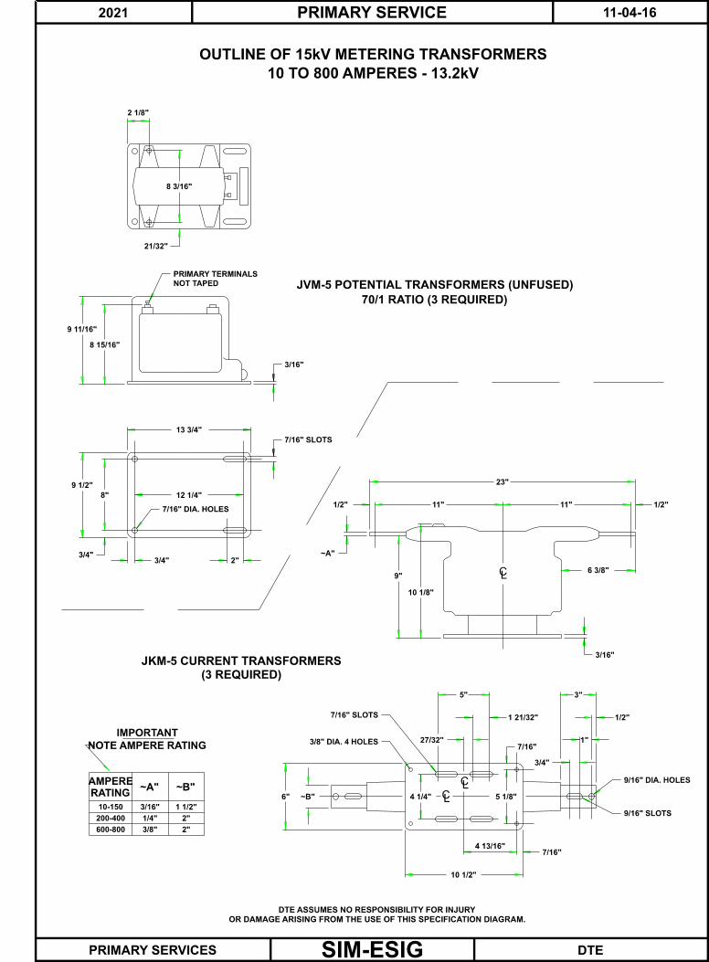
SIM-ESIG
2021 11-04-16PRIMARY SERVICE
DTEPRIMARY SERVICES
OR DAMAGE ARISING FROM THE USE OF THIS SPECIFICATION DIAGRAM.
DTE ASSUMES NO RESPONSIBILITY FOR INJURY
OUTLINE OF 15kV METERING TRANSFORMERS
10 TO 800 AMPERES - 13.2kV
70/1 RATIO (3 REQUIRED)
JVM-5 POTENTIAL TRANSFORMERS (UNFUSED)
10 1/2"
3/8" DIA. 4 HOLES
IMPORTANT
NOTE AMPERE RATING
600-800
10-150
(3 REQUIRED)
JKM-5 CURRENT TRANSFORMERS
7/16" SLOTS
6" ~B" 4 1/4"
5"
27/32"
~A"
9"
10 1/8"
23"
1/2" 11"
3/4"
~A"RATING
AMPERE~B"
200-400
3/16"
2"3/8"
2"1/4"
1 1/2"
7/16" DIA. HOLES
2"
7/16" SLOTS
3/4"
NOT TAPED
PRIMARY TERMINALS
3/16"
21/32"
12 1/4"8"
9 1/2"
13 3/4"
8 15/16"
9 11/16"
8 3/16"
2 1/8"
9/16" SLOTS
7/16"4 13/16"
7/16"
5 1/8"
1 21/32"
3"
6 3/8"
3/16"
1/2"11"
9/16" DIA. HOLES
1/2"
3/4"
1"
CL
LC
CL

SIM-ESIG
2021 11-04-17PRIMARY SERVICE
DTEPRIMARY SERVICES
OR DAMAGE ARISING FROM THE USE OF THIS SPECIFICATION DIAGRAM.
DTE ASSUMES NO RESPONSIBILITY FOR INJURY
1200 TO 4000 AMPERES - 13.2kV
OUTLINE OF 15KV METERING TRANSFORMERS
70/1 RATIO (3 REQUIRED)
JVM-5 POTENTIAL TRANSFORMERS (UNFUSED)
4 HOLES
9/16" DIA.
BE HINGED, BOLTED AND PADLOCKED.
IN SWITCHGEAR SUPERSTRUCTURE. DOOR TO
POTENTIAL TRANSFORMERS MAY BE LOCATED
5 3/4"
1/4"
1/4" SPACING
7/16" DIA. 4 HOLES
1
2
3
42
2
1
1
(3 REQUIRED)
JCM-5 CURRENT TRANSFORMERS
FIGURE 1
1/2"
4"
1 1/8"
1 3/4"
ALTERNATE LOCATION:
5 3/4"
9 1/2"
~A"
2 1/4"
IMPORTANT
NOTE AMPERE RATING
OF PADS
NUMBER
12 11/16"
12 7/16"
12 3/16"
FIG.
11 11/16"
4000
3000
2000-2500
1200-1500
3/4"
~A"RATING
AMPERE
7/16" DIA. HOLES
2"
7/16" SLOTS
3/4"
NOT TAPED
PRIMARY TERMINALS
3/16"
21/32"
12 1/4"8"
9 1/2"
13 3/4"
8 15/16"
9 11/16"
8 3/16"
2 1/8"
FIGURE 2
1 3/4"
1 3/4"
1 1/4"
6"
6 HOLES
9/16" DIA. 1/2"
1 3/4"
27"
CONTACT SURFACE
3" MIN.
1/4"
7/16" SLOTS7/16" SLOTS
7"
6 3/8"
7 3/8"
5"
1 21/32"
27/32"
4 1/4"CL

2021 PRIMARY SERVICES 11-5-1
SIM-ESIG
SINGLE CONDUCTOR PRIMARY SERVICE CABLE
All service cable must be approved by Primary Services prior to purchase. All singleconductor cable must be 15kV class. Cable must be a minimum of #2 copper unlessotherwise approved by PSR. Corrosion resistant covering may be required. Thefollowing types of single conductor cable are acceptable for use as primary servicecable on the DTE system.
Cross-Linked Polyethylene Concentric Cable as per DTE Specification 527, revisionL or later.
Ethylene Propylene Rubber, DTE Specification 520, revision E or later.
Note:
1. If copper tape shielded cable is used an additional 2/0, grounded conductor willbe pulled into the same conduit as the power cable. The conductor shall be 2/0copper with 600V insulation (a smaller conductor may be adequate in somecases - consult DTE Primary Services).
2. All cables must meet Local Code requirements.

2021 PRIMARY SERVICES 11-5-2
SIM-ESIG
RECOMMENDED JOINTS AND TERMINATIONSFOR 15 kV CROSS-LINKED POLYETHYLENE AND
POLYETHYLENE CONCENTRIC SINGLE CONDUCTORPRIMARY CABLES
(See Page 11-5-1 for Acceptable Cables)
Termination’s Indoor Only*PLM Type FSDT
RAYCHEM CAT. HVT-150-G Series3M Type Quickterm, 5600 Series & 7600 Series
Termination’s Indoor or Outdoor3M Type 5600 Quickterm with Skirts & 7600 Series
RAYCHEM CAT. HVT-150-SG SeriesG&W Type PAT 1700 or LCT
Elastimold R2T15 SeriesPLM Type FSDW
Splices3M Catalog No. 5400 & 5500 Series
RAYCHEM Catalog HVS-C-S-1520SG&W Style 225 or 370
Elastimold 250 & 650 SeriesPLM Catalog No. SA to SE-15RTE Type 2603890A
Plymouth Plyjoint
All terminal connectors must be long barrel compression lugs with two holes, National ElectricalManufacturers Association (NEMA: 1-3/4” spaced, or bendable spike lugs).
Specify insulation thickness and cable diameter when ordering termination’s and splices. For anyadditional information, contact DTE Primary Services.
Loadbreak Elbows and Bushings for Deadfront Transformers
FOR SPECIAL APPLICATIONS ONLY:
Elastimold 167LRT 1601A4 SeriesRTE
CooperType 2609459 A_ _/2604797B01MLE215 Series
*An indoor installation is one that is in a structure that is conditioned for human comfort. Thisdoes not include outdoor meter units, switchgear or transformers. Installations coming within thisdefinition will normally have proper humidity assuring that indoor terminations will be installed indry locations.

2021 PRIMARY SERVICES 11-5-3
SIM-ESIG
FUSED LOADBREAK INTERRUPTER SWITCHES, ACCEPTABLE TO DTEELECTRIC COMPANY FOR PRIMARY SERVICE EQUIPMENT
Manufacturers Manufacturers Closing Amps(RMS Asymmetrical)
Federal PacificAuto-Jet Switch 600A
Auto-Jet Switch 1200A40,000A61,000A
S & C Electric CompanyMini-Rupter 600A
Alduti-Rupter 1200A40,000A61,000A
Powercon CorporationType PIF 600 AType PIF 1200 A
40,000A61,000A
Square D CompanyType HVL 600A 40,000A
EatonType MVS 600A 40,000A
All manufacturers must use one of these approved loadbreak switches in theirswitchgear.

2021 PRIMARY SERVICES 11-5-4
LOADBREAK SWITCHGEAR REQUIREMENTSFOR DTE ELECTRIC PRIMARY CUSTOMERS
This document contains the requirements and recommendations for loadbreakswitchgear and meter compartments intended for installation as service equipment onthe DTE Electric system. It includes construction requirements as well as drawingsshowing several acceptable arrangements for one and two-line installations. DTE mustfirst review and approve shop drawings of equipment prior to purchase or install.
Loadbreak switches, which have been approved, are listed on Page 11-5-3 of theElectrical Service Installation Guide.
Switch
1. The loadbreak switch(s) shall be three-phase, gang operated, single throw, motoror manual operation. It shall be quick-closing and quick-opening and beindependent of the operating handle or motor drive once the blades have startedindependent movement. Manual switches shall not be awkward, difficult to reach,or difficult to close or open. There must be a means of deactivating and securingany automatic transfer scheme.
2. Switch elements shall be mounted on a metal, grounded frame that grounds theleakage path parallel to the open switch to provide adequate protection in the openposition.
3. Switches using a chain link drive shall have a barrier installed to prevent a brokenchain from contacting energized equipment.
4. Inverted switches are NOT permitted
5. Multi line customers are required to have an automatic throw over and automaticthrowback scheme unless exempted by DTE
Fusing
Type and style of fuse must be approved by DTE Primary Services. The manufacturermust provide spare fuses to service switchgear. Fuses must be hinged (except fordouble barrel fuses).
Clearances
The following table specifies voltage clearances to be maintained throughout theswitchgear including bus-work, cable terminations, metering equipment and any otherhigh voltage equipment.
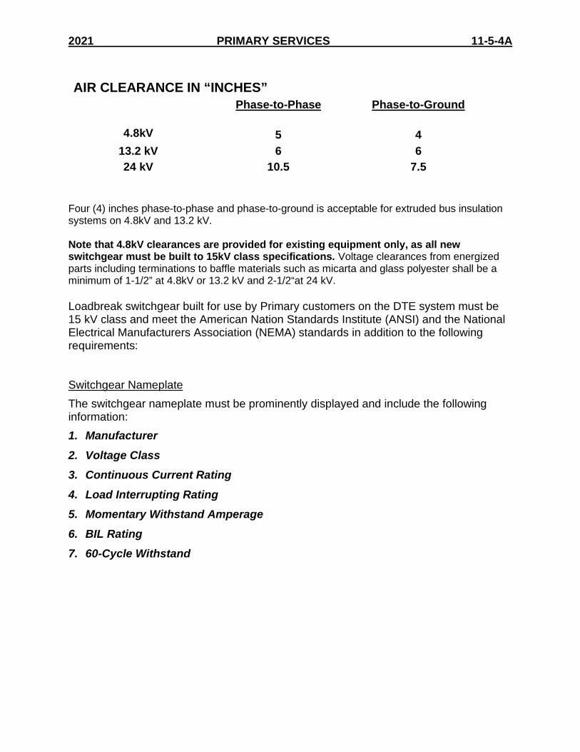
2021 PRIMARY SERVICES 11-5-4A
AIR CLEARANCE IN “INCHES”Phase-to-Phase Phase-to-Ground
4.8kV 5 4
13.2 kV 6 6
24 kV 10.5 7.5
Four (4) inches phase-to-phase and phase-to-ground is acceptable for extruded bus insulationsystems on 4.8kV and 13.2 kV.
Note that 4.8kV clearances are provided for existing equipment only, as all newswitchgear must be built to 15kV class specifications. Voltage clearances from energizedparts including terminations to baffle materials such as micarta and glass polyester shall be aminimum of 1-1/2” at 4.8kV or 13.2 kV and 2-1/2“at 24 kV.
Loadbreak switchgear built for use by Primary customers on the DTE system must be15 kV class and meet the American Nation Standards Institute (ANSI) and the NationalElectrical Manufacturers Association (NEMA) standards in addition to the followingrequirements:
Switchgear Nameplate
The switchgear nameplate must be prominently displayed and include the followinginformation:
1. Manufacturer
2. Voltage Class
3. Continuous Current Rating
4. Load Interrupting Rating
5. Momentary Withstand Amperage
6. BIL Rating
7. 60-Cycle Withstand
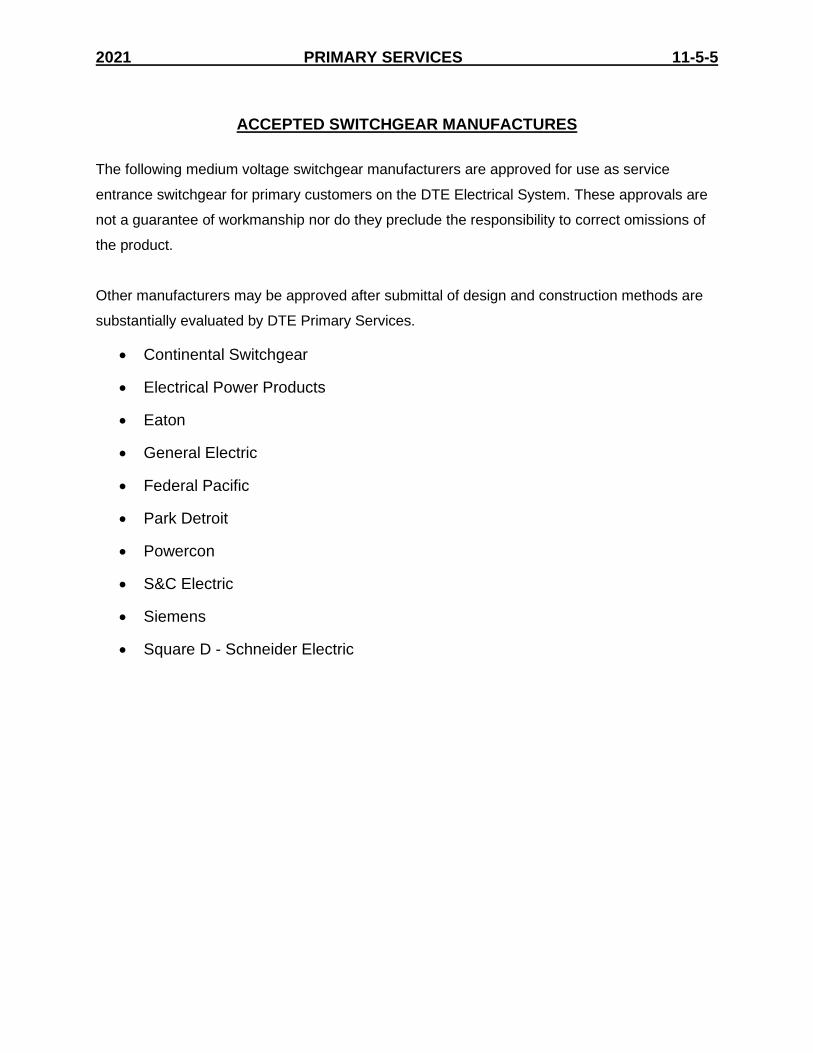
2021 PRIMARY SERVICES 11-5-5
ACCEPTED SWITCHGEAR MANUFACTURES
The following medium voltage switchgear manufacturers are approved for use as service
entrance switchgear for primary customers on the DTE Electrical System. These approvals are
not a guarantee of workmanship nor do they preclude the responsibility to correct omissions of
the product.
Other manufacturers may be approved after submittal of design and construction methods are
substantially evaluated by DTE Primary Services.
Continental Switchgear
Electrical Power Products
Eaton
General Electric
Federal Pacific
Park Detroit
Powercon
S&C Electric
Siemens
Square D - Schneider Electric

2021 PRIMARY SERVICES 11-5-6
SIM-ESIG
Heating Element
Switchgear intended for outdoor use or for use in areas of high humidity must have stripheaters installed in each cubicle. Strip heater wiring must have high-temperatureinsulation and be trained away from proximity to the heater element. For longevity a220V heater strip operated at 120V is recommended.
Locking Devices
DTE uses padlocks with a 3/8” shackle for equipment security and DTE HEC. Thefollowing items must have provisions for the installation of padlocks with a 3/8” shackle.
1. Switch handles for manually operated switches and spring-charging handles.
2. Doors of incoming line cubicles and feeder positions.
3. Doors of DTE revenue metering cubicles.
4. Doors of cubicles that contain control power transformer secondary knifeswitches, motor-control secondary switches, or any other points that may beHEC by DTE.
Metering Cubicle
The metering cubicle shall be easily accessible by a hinged, lockable door and remainunder control of DTE. Also, an inner door screen barrier, hinged with “Danger HighVoltage” sign. Refer to drawing PC894-41 in appendix for details. No customer-ownedcomponents (e.g.; line potential transformers, surge arresters, etc..) will be in themetering cubicle. High-voltage clearances and clearance to baffles will be consistentwith that of the entire switchgear (See page 11-5-5).
The potential transformer shelf will be horizontal and of adequate width toaccommodate three (3) transformers in an upright position while maintaining previouslyspecified clearances. See sample drawing on Page 11-5-27 for minimum spacing ofmetering cubicles with or without baffles. Shelf must be a minimum of 18” above thefloor.
Should Primary cable be greater than size 4/0 AWG, the meter compartment then musthave insulator supported bus bars to terminate and support the cables.

2021 PRIMARY SERVICES 11-5-7
SIM-ESIG
Positioning of potential and current transformers must allow visual inspection of primaryand secondary connections and serial numbers of same while equipment is energized.The 15kV potential transformer cable will be provided by DTE as well as the multi-conductor cable for the potential and current transformer secondaries. Contractor willprovide DTE with length required to reach DTE meter connection cabinet from the metercubicle.
Meter cubicle shall have welded condulets for training of secondaries to the outgoingconduit. The conduit from the meter cubicle to the meter connection cabinet will be 1-1/2” rigid steel and contain the potential transformer and current transformer secondarycable and a separate, #2 copper ground conductor with 600V insulation. Fusedmetering potential transformers may be required when metering is on the utility side ofthe main switch and the customer is served from all-underground power lines, industrialsubstation, services 24kV and above, or the available fault currents exceed 7,000A at13.2kV or 10,000A at 4.8kV. Consult DTE Primary Services.
Switchgear for Two-Line Operation
Adjoining switchgear positions that contain both incoming lines must be gas-proofed asoutlined in the Gas-Proofing section of this publication (Page 11-5-9). See exampledrawings for suggested bushing locations.
Switchgear fed from more than one DTE line must have an interlock system to preventthe customer from electrically paralleling any two DTE lines. A key interlock system formanual switchgear or an electrical interlock system for automatic switchgear canaccomplish this. An extra key or key-operated electrical “Interlock bypass” switch mustbe provided to permit paralleling by DTE personnel under controlled conditions. The keywill remain under sole control of DTE Primary Services. Reference DTE control schemeSpec drawings (Page 11-5-8).
Automatic Loadbreak Switchgear
Switchgear built for automatic operation shall conform to conditions previouslymentioned for two-line operation as well as meeting the following requirements:
1. Must have an automatic-manual switch.
2. May have a key-operated “Interlock-bypass” switch.
3. Must have an approved throw over scheme (drawings provided to DTE PrimaryServices).
4. Potential transformers, which are located on the line side of the main switch, musthave secondaries equipped with a gang operated open knife-blade switch (bladesde-energized when open) appropriately located for ease of DTE HEC. Line potentialtransformers are to be fused. Fuses must be easily accessible by a hinged door.

2021 PRIMARY SERVICES 11-5-8
SIM-ESIG
5. There must be a means of mechanically and electrically disabling the switchoperator (motor, spring or spring charging mechanism) and a means of padlockingthe switch operator to prevent closing when DTE HEC is required.
6. A three-phase voltmeter shall be mounted on the front side of the switchgear for eachline to prove to the operator that each line is energized.
DTE Specification Drawings
The following DTE specification drawings are available in the appendix:
5PC894-38 - Two Line Automatic Throw Over Scheme5PC894-39 - Parallel/Radial Operation Control Scheme
PC894-40 - Partial Schematic – Normal/Alternate A.T.O. Scheme5PC894-41 - Metering Equipment Compartment
PC894-42 - Interruptible Service Control Scheme5PC894-43 - Two Line A.T.O./Line Select A.T.O. Scheme
.

2021 PRIMARY SERVICES 11-5-9
SIM-ESIG
Gas Proof Bushings
Adjacent compartments, containing separate incoming services, and tie compartments must begas proofed to prevent the transfer of ionized gasses during certain fault conditions. This may beaccomplished in either of the following ways:
A. Preferred Arrangement
The preferred arrangement employs the use of a gas proof bushing and mounting flangeassembly, 15 kV class with a 95 kV BIL rating as shown on Page 11-5-10. This bushing shouldalways be mounted in a steel wall between incoming line compartments or in the horizontal wall(steel shelf) between the upper and lower sections of the tie switch compartment. It isrecommended that bushing specifications be submitted to Primary Services for approval prior tothe switchgear being built. Construction of the wall between adjoining compartments should alsolimit the transfer of gas to the adjoining compartment.
B. Alternative Arrangement
The alternative arrangement employs the use of an oval or rectangular, 15 kV 95 kV BIL ratedinsulator (see Page 11-5-11) having a minimum leakage distance of 1” per kV line to groundvoltage (8” for 15 kV class switchgear) inserted between the bus bar and the sheet metal orinsulating board compartment wall. The air space between the bus bar and insulator should beless than 1/8” on all sides of the bus and be sealed with duct seal, RTV, or in some otherappropriate manner. The bus bar must have appropriate non-tracking insulation extending 6” oneither side of the wall or shelf. Insulated boards must have 1/4” minimum thickness to containforces developed in certain types of faults. Again, construction of walls between adjoiningcompartments should limit the transfer of gas between them.
Insulators
Porcelain or cycloaliphatic epoxy insulators are required in cubicles containing DTE meterinstrument transformers & incoming power cable, and are recommended throughout theswitchgear line-up. Glass polyester products are not acceptable.
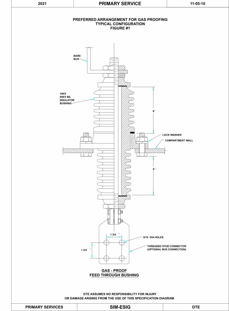
PREFERRED ARRANGEMENT FOR GAS PROOFING
TYPICAL CONFIGURATION
FIGURE #1
BARE
BUS
15KV
95KV BIL
INSULATOR
BUSHING
6
6
COMPARTMENT WALL
9/16 DIA HOLES
1 3/4
THREADED STUD CONNECTOR
(OPTIONAL BUS CONNECTION)
GAS - PROOF
FEED THROUGH BUSHING
1 3/4
LOCK WASHER
DTESIM-ESIG
PRIMARY SERVICE
PRIMARY SERVICES
DTE ASSUMES NO RESPONSIBILITY FOR INJURY
OR DAMAGE ARISING FROM THE USE OF THIS SPECIFICATION DIAGRAM.
2021 11-05-10
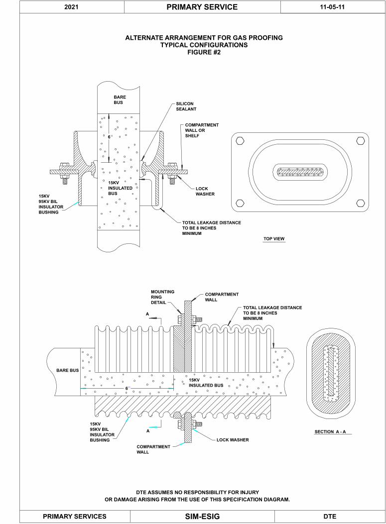
ALTERNATE ARRANGEMENT FOR GAS PROOFING
TYPICAL CONFIGURATIONS
FIGURE #2
TOTAL LEAKAGE DISTANCE
TO BE 8 INCHES
MINIMUM
COMPARTMENT
WALL OR
SHELF
15KV
INSULATED
BUS
6
15KV
95KV BIL
INSULATOR
BUSHING
BARE
BUS
COMPARTMENT
WALL
MOUNTING
RING
DETAIL
BARE BUS
15KV
INSULATED BUS
15KV
95KV BIL
INSULATOR
BUSHING
TOTAL LEAKAGE DISTANCE
TO BE 8 INCHES
MINIMUM
6
SECTION A - A
A
A
TOP VIEW
SILICON
SEALANT
COMPARTMENT
WALL
LOCK WASHER
LOCK
WASHER
DTE
11-05-11
SIM-ESIG
PRIMARY SERVICE
PRIMARY SERVICES
DTE ASSUMES NO RESPONSIBILITY FOR INJURY
OR DAMAGE ARISING FROM THE USE OF THIS SPECIFICATION DIAGRAM.
2021
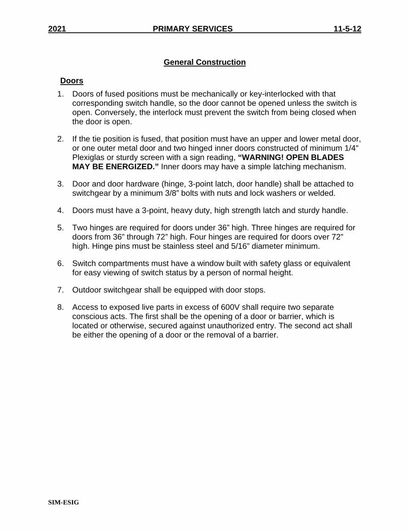
2021 PRIMARY SERVICES 11-5-12
SIM-ESIG
General Construction
Doors
1. Doors of fused positions must be mechanically or key-interlocked with thatcorresponding switch handle, so the door cannot be opened unless the switch isopen. Conversely, the interlock must prevent the switch from being closed whenthe door is open.
2. If the tie position is fused, that position must have an upper and lower metal door,or one outer metal door and two hinged inner doors constructed of minimum 1/4"Plexiglas or sturdy screen with a sign reading, “WARNING! OPEN BLADESMAY BE ENERGIZED.” Inner doors may have a simple latching mechanism.
3. Door and door hardware (hinge, 3-point latch, door handle) shall be attached toswitchgear by a minimum 3/8” bolts with nuts and lock washers or welded.
4. Doors must have a 3-point, heavy duty, high strength latch and sturdy handle.
5. Two hinges are required for doors under 36” high. Three hinges are required fordoors from 36” through 72” high. Four hinges are required for doors over 72”high. Hinge pins must be stainless steel and 5/16” diameter minimum.
6. Switch compartments must have a window built with safety glass or equivalentfor easy viewing of switch status by a person of normal height.
7. Outdoor switchgear shall be equipped with door stops.
8. Access to exposed live parts in excess of 600V shall require two separateconscious acts. The first shall be the opening of a door or barrier, which islocated or otherwise, secured against unauthorized entry. The second act shallbe either the opening of a door or the removal of a barrier.

2021 PRIMARY SERVICES 11-5-13
SIM-ESIG
Miscellaneous
1. All components are to be mounted in a suitable and adequate housing ofminimum 11-gauge steel or UL equivalent. Outdoor enclosures shall be suitablyrain-proof, dust-proof, and provided with a heater and ventilation adequate toprevent water condensation. Provide air filter material behind vents to filter aircontaminants, snow, etc., from entering switchgear. Louvers shall be screened toprevent insertion of foreign objects into switchgear. Indoor enclosures should berain proof if located in an area susceptible to water damage.
2. All installations shall be tamper-proof commensurate with the degree of accessby unqualified personnel. Warning signs indicating “DANGER! HIGH VOLTAGE– KEEP OUT!” and the voltage level shall be provided on the outside of doors,panels or barriers that can be removed to expose energized equipment.Reference NEMA Standards No. 260-1996.
3. Inadequate components such as cable bus, 5kV materials, etc., will not beacceptable.
4. Compartments containing components such as current and potentialtransformers, surge arresters, or any components that may require periodicinspection, maintenance or testing should be easily accessible by a hinged,lockable door. There should be no hazard associated with reaching overenergized equipment.
5. Arresters should be electrically located as near as possible to the componentsthat are intended to protect yet located where a violent failure of the arrester willnot damage other components such as transformer windings, cable terminationsor current and potential transformers. Baffles may be required to accomplish thisand must provide for easy inspection of the arresters while energized in case ofsuspected failures.
6. Arresters are not to be installed on the utility side of a main switch whenconnected to T-tapped all-underground power lines.
7. All line side bus work and components must be supported by 15kV, 95kV BILrated porcelain or cycloaliphatic insulators.
8. On multiple service installations, the incoming service cable cubicle must beconstructed so that workers can work on the cable terminations without thehazard of leaning over an energized switch, bus or other equipment. Provisions(e.g., horizontal support shelf) must also be made to prevent tools or otherequipment from dropping into energized equipment while working onterminations.
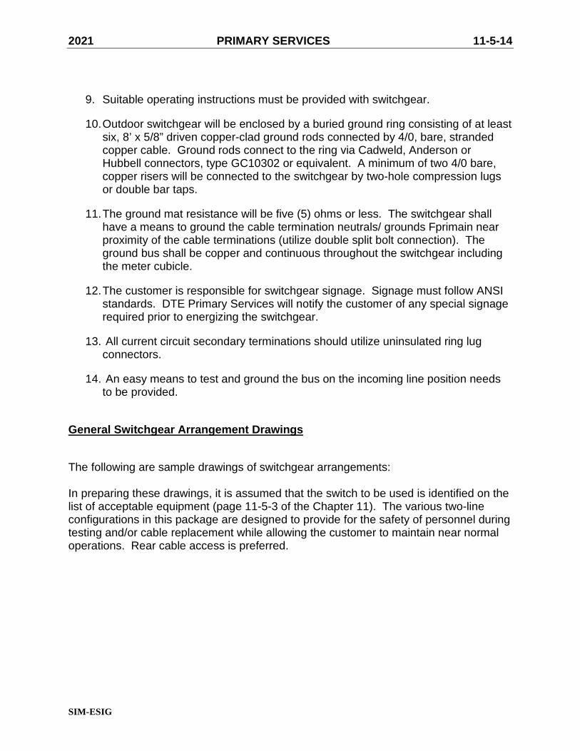
2021 PRIMARY SERVICES 11-5-14
SIM-ESIG
9. Suitable operating instructions must be provided with switchgear.
10.Outdoor switchgear will be enclosed by a buried ground ring consisting of at leastsix, 8’ x 5/8” driven copper-clad ground rods connected by 4/0, bare, strandedcopper cable. Ground rods connect to the ring via Cadweld, Anderson orHubbell connectors, type GC10302 or equivalent. A minimum of two 4/0 bare,copper risers will be connected to the switchgear by two-hole compression lugsor double bar taps.
11.The ground mat resistance will be five (5) ohms or less. The switchgear shallhave a means to ground the cable termination neutrals/ grounds Fprimain nearproximity of the cable terminations (utilize double split bolt connection). Theground bus shall be copper and continuous throughout the switchgear includingthe meter cubicle.
12.The customer is responsible for switchgear signage. Signage must follow ANSIstandards. DTE Primary Services will notify the customer of any special signagerequired prior to energizing the switchgear.
13. All current circuit secondary terminations should utilize uninsulated ring lugconnectors.
14. An easy means to test and ground the bus on the incoming line position needsto be provided.
General Switchgear Arrangement Drawings
The following are sample drawings of switchgear arrangements:
In preparing these drawings, it is assumed that the switch to be used is identified on thelist of acceptable equipment (page 11-5-3 of the Chapter 11). The various two-lineconfigurations in this package are designed to provide for the safety of personnel duringtesting and/or cable replacement while allowing the customer to maintain near normaloperations. Rear cable access is preferred.
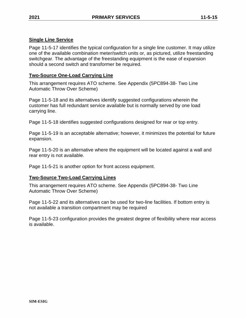
2021 PRIMARY SERVICES 11-5-15
SIM-ESIG
Single Line Service
Page 11-5-17 identifies the typical configuration for a single line customer. It may utilizeone of the available combination meter/switch units or, as pictured, utilize freestandingswitchgear. The advantage of the freestanding equipment is the ease of expansionshould a second switch and transformer be required.
Two-Source One-Load Carrying Line
This arrangement requires ATO scheme. See Appendix (5PC894-38- Two LineAutomatic Throw Over Scheme)
Page 11-5-18 and its alternatives identify suggested configurations wherein thecustomer has full redundant service available but is normally served by one loadcarrying line.
Page 11-5-18 identifies suggested configurations designed for rear or top entry.
Page 11-5-19 is an acceptable alternative; however, it minimizes the potential for futureexpansion.
Page 11-5-20 is an alternative where the equipment will be located against a wall andrear entry is not available.
Page 11-5-21 is another option for front access equipment.
Two-Source Two-Load Carrying Lines
This arrangement requires ATO scheme. See Appendix (5PC894-38- Two LineAutomatic Throw Over Scheme)
Page 11-5-22 and its alternatives can be used for two-line facilities. If bottom entry isnot available a transition compartment may be required
Page 11-5-23 configuration provides the greatest degree of flexibility where rear accessis available.

2021 PRIMARY SERVICES 11-5-16
SIM-ESIG

SYMMETRICALLY OPPOSITE PERMISSIBLE
N.C. LB
LOAD
INCOMING
LINE
ONE LOAD CARRYING LINE
ONE SOURCE
DTE
11-05-17
SIM-ESIG
PRIMARY SERVICE
PRIMARY SERVICES
2021
DTE ASSUMES NO RESPONSIBILITY FOR INJURY
OR DAMAGE ARISING FROM THE USE OF THIS SPECIFICATION DIAGRAM.

LB
NOTES:
ELECTRICAL INTERLOCK AND AUTOMATIC THROWOVER
ONE LOAD CARRYING LINE
TWO SOURCES
N.C.
NORMAL T.O.
LOAD
N.O.
N.C.
N.C.
N.O.
FED FROM TOP
SWITCHGEAR APPLICATIONS.
FEEDER LOADBREAK SWITCH OPTIONAL.
SERVICE CABLES ENTER AT REAR OF COMPARTMENT,
ACCESSIBLE VIA HINGED DOORS.
SERVICE CABLES ENTER AT TOP OF COMPARTMENT, ACCESSIBLE
VIA HINGED DOORS. PROTECTIVE SHELF REQUIRED.
ADDITIONAL BAYS AS REQUIRED.
(PREFERRED METHOD)
INCOMING LINE COMPARTMENTS
GAS BARRIER REQUIRED. 15KV, 95KV BIL, ALL
FED FROM REAR COMPARTMENTS
INCOMING LINE COMPARTMENTS
APPLICABLE TO THE
FOLLOWING:
COMPARTMENTS
11-5-19
11-5-24
11-5-18
11-5-23
LOAD
BUS NOT TO BE IN PHYSICAL CONTACT WITH SHELF
MINIMUM 1 1/2" SPACING. INSULATE BUS IN VICINITY
OF SHELF FOR 15 KV, 95KV BIL.
(ALTERNATIVE METHOD)
DTESIM-ESIG
PRIMARY SERVICE
PRIMARY SERVICES
DTE ASSUMES NO RESPONSIBILITY FOR INJURY
OR DAMAGE ARISING FROM THE USE OF THIS SPECIFICATION DIAGRAM.
2021 11-05-18
1
2
3
4
6
E1
5 5
E
4
E
1
62
5
4
3 3

N.C.
ONE LOAD CARRYING LINE (OPTION A)
TWO SOURCES
N.O.
LOAD
T.O.NORMAL
"A" "B"
NOTES:
GAS BARRIER REQUIRED AT "A" AND "B".
SERVICE CABLES ENTER AT REAR OF COMPARTMENT
ACCESSIBLE VIA HINGED DOOR.
TOP FED ALTERNATIVE)
DTE
11-05-19
SIM-ESIG
PRIMARY SERVICE
PRIMARY SERVICES
DTE ASSUMES NO RESPONSIBILITY FOR INJURY
OR DAMAGE ARISING FROM THE USE OF THIS SPECIFICATION DIAGRAM.
2021
1
2
2
1
2
(SEE 11-5-18 FOR
E
ELECTRICAL INTERLOCK AND AUTOMATIC THROWOVERE
3
OF SHELF FOR 15 KV, 95KV BIL.
MINIMUM 1 1/2" SPACING. INSULATE BUS IN VICINITY
BUS NOT TO BE IN PHYSICAL CONTACT WITH SHELF
3 3

NOTES:
ONE LOAD CARRYING (OPTION B)
TWO SOURCES
N.O.
LOAD
2
GAS BARRIER REQUIRED
2
ELECTRICAL INTERLOCK AND AUTOMATIC THROWOVER
BUS NOT TO BE IN PHYSICAL CONTACT WITH SHELF.
MINIMUM 1 1/2" SPACING. INSULATE BUS IN VICINITY
OF SHELF FOR 15KV, 95KV BIL.
DTESIM-ESIG
PRIMARY SERVICE
PRIMARY SERVICES
DTE ASSUMES NO RESPONSIBILITY FOR INJURY
OR DAMAGE ARISING FROM THE USE OF THIS SPECIFICATION DIAGRAM.
1
N.C.
2
NORMAL T.O.
"A" "B"
2021 11-05-20
11
E
E

NOTES:
ONE LOAD CARRYING (OPTION C)
TWO SOURCES
LINE 1
NORMAL
LINE 2
T.O.
N.C. N.O.
LOAD
GAS BARRIER REQUIRED
ELECTRICAL INTERLOCK AND AUTOMATIC THROWOVER
BUS NOT TO BE IN PHYSICAL CONTACT WITH SHELF.
MINIMUM 1 1/2" SPACING. INSULATE BUS IN VICINITY
OF SHELF FOR 15KV, 95KV BIL.
DTE
11-05-21
SIM-ESIG
PRIMARY SERVICE
PRIMARY SERVICES
2021
DTE ASSUMES NO RESPONSIBILITY FOR INJURY
OR DAMAGE ARISING FROM THE USE OF THIS SPECIFICATION DIAGRAM.
22
E
1
1
2
E
S.K
AS
SE
M

N.C.
N.O.
N.C.
TWO LOAD CARRYING LINES
LINE 1 LINE 2
NOTES:
ELECTRICAL INTERLOCK AND AUTOMATIC THROWOVER
LOADLOAD
DTESIM-ESIG
PRIMARY SERVICE
PRIMARY SERVICES
DTE ASSUMES NO RESPONSIBILITY FOR INJURY
OR DAMAGE ARISING FROM THE USE OF THIS SPECIFICATION DIAGRAM.
2021 11-05-22
E
E
1
OF SHELF FOR 15 KV, 95KV BIL.
MINIMUM 1 1/2" SPACING. INSULATE BUS IN VICINITY
BUS NOT TO BE IN PHYSICAL CONTACT WITH SHELF
1 1
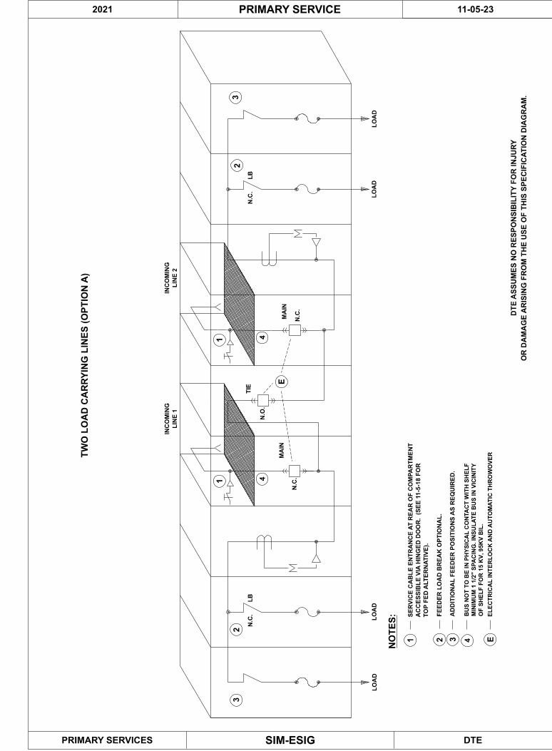
LB
NO
TE
S:
N.C
.
TW
O L
OA
D C
AR
RY
ING
LIN
ES
(O
PT
ION
A)
N.C
.
N.O
.
N.C
.
LB
N.C
.
INC
OM
ING
LIN
E 1
INC
OM
ING
LIN
E 2
MA
INM
AIN
TIE
1 2 3 E
AD
DIT
ION
AL
FE
ED
ER
PO
SIT
ION
S A
S R
EQ
UIR
ED
.
EL
EC
TR
ICA
L I
NT
ER
LO
CK
AN
D A
UT
OM
AT
IC T
HR
OW
OV
ER
FE
ED
ER
LO
AD
BR
EA
K O
PT
ION
AL
.
3
11
23
2
LO
AD
LO
AD
LO
AD
LO
AD
SE
RV
ICE
CA
BL
E E
NT
RA
NC
E A
T R
EA
R O
F C
OM
PA
RT
ME
NT
AC
CE
SS
IBL
E V
IA H
ING
ED
DO
OR
. (
SE
E 1
1-5
-18
FO
R
TO
P F
ED
AL
TE
RN
AT
IVE
).
DTE
11-05-23
SIM-ESIG
PRIMARY SERVICE
PRIMARY SERVICES
2021
DT
E A
SS
UM
ES
NO
RE
SP
ON
SIB
ILIT
Y F
OR
IN
JU
RY
OR
DA
MA
GE
AR
ISIN
G F
RO
M T
HE
US
E O
F T
HIS
SP
EC
IFIC
AT
ION
DIA
GR
AM
.
E
4
OF
SH
EL
F F
OR
15
KV
, 9
5K
V B
IL.
MIN
IMU
M 1
1/2
" S
PA
CIN
G. IN
SU
LA
TE
BU
S I
N V
ICIN
ITY
BU
S N
OT
TO
BE
IN
PH
YS
ICA
L C
ON
TA
CT
WIT
H S
HE
LF
44

LB
LB
N.C
.
N.C
.
N.O
.
N.C
.
LB
N.C
.
TW
O L
OA
D C
AR
RY
ING
LIN
ES
(O
PT
ION
B)
LIN
E 1
LIN
E 2
FU
TU
RE
FU
TU
RE
NO
TE
S:
1 2 3 E
SE
RV
ICE
CA
BL
E E
NT
RA
NC
E A
T R
EA
R O
F C
OM
PA
RT
ME
NT
AC
CE
SS
IBL
E V
IA H
ING
ED
DO
OR
.
AD
DIT
ION
AL
FE
ED
ER
PO
SIT
ION
S A
S R
EQ
UIR
ED
.
EL
EC
TR
ICA
L I
NT
ER
LO
CK
AN
D A
UT
OM
AT
IC T
HR
OW
OV
ER
(SE
E 1
1-7
-22
FO
R
FE
ED
ER
LO
AD
BR
EA
K O
PT
ION
AL
.
1
23
1
23
LO
AD
LO
AD
TO
P F
ED
AL
TE
RN
AT
IVE
).
DTESIM-ESIG
PRIMARY SERVICE
PRIMARY SERVICES
DTE ASSUMES NO RESPONSIBILITY FOR INJURY
OR DAMAGE ARISING FROM THE USE OF THIS SPECIFICATION DIAGRAM.
2021 11-05-24
E
4
OF
SH
EL
F F
OR
15
KV
, 9
5K
V B
IL.
MIN
IMU
M 1
1/2
" S
PA
CIN
G. IN
SU
LA
TE
BU
S I
N V
ICIN
ITY
BU
S N
OT
TO
BE
IN
PH
YS
ICA
L C
ON
TA
CT
WIT
H S
HE
LF
44

LB
N.C
.L
BN
.C.
TW
O L
OA
D C
AR
RY
ING
LIN
ES
(O
PT
ION
C)
N.C
.N
.C.
MA
IN
TIE
MA
IN
LB
LO
AD
LO
AD
LIN
E 1
LIN
E 2
12
E
N.O
.
12
LO
AD
LO
AD
NO
TE
S:
1 2 E
FE
ED
ER
LO
AD
BR
EA
K O
PT
ION
AL
.
AD
DIT
ION
AL
FE
ED
ER
LO
AD
BR
EA
KS
AS
RE
QU
IRE
D.
EL
EC
TR
ICA
L I
NT
ER
LO
CK
AN
D A
UT
OM
AT
IC T
HR
OW
OV
ER
BU
S N
OT
TO
BE
IN
PH
YS
ICA
L C
ON
TA
CT
WIT
H S
HE
LF
. M
INIM
UM
1 1
/2" S
PA
CIN
G.
INS
UL
AT
E B
US
IN
VIC
INIT
Y O
F S
HE
LF
FO
R 1
5K
V, 95K
V B
IL.
DTE
11-05-25
SIM-ESIG
PRIMARY SERVICE
PRIMARY SERVICES
DT
E A
SS
UM
ES
NO
RE
SP
ON
SIB
ILIT
Y F
OR
IN
JU
RY
OR
DA
MA
GE
AR
ISIN
G F
RO
M T
HE
US
E O
F T
HIS
SP
EC
IFIC
AT
ION
DIA
GR
AM
.
2021
33
3
E

MINIMUM METERING CUBICLE CLEARANCES (36 INCH WIDE)
FOR POTENIAL TRANSFORMERS
TOP VIEW
POTENTIAL
TRANSFORMER
FRONT VIEW
13.2 kV MINIMUM SHELF SPACING
TOP VIEW
4.8 kV SPACING
(BAFFLES NOT REQUIRED)
2"
8"
36"
9"
8" 8"
POTENTIAL
TRANSFORMER
15"
DTESIM-ESIG
PRIMARY SERVICE
PRIMARY SERVICES
DTE ASSUMES NO RESPONSIBILITY FOR INJURY
OR DAMAGE ARISING FROM THE USE OF THIS SPECIFICATION DIAGRAM.
HV TERMINALS
BAFFLES
REQ W/ 36"
CUBICLE
5"
8"
8"
4"
36"
CONDUITS TO
TRAIN POT SEC.
WIRING
FRONT OF UNIT
COPPER
GRD BUS
2021 11-05-26
6" 8" 6"
13.2 kV
CUBICLE
REQ W/ 36"
BAFFLES
4" 2"
(FOR MAINTENANCES PURPOSES ONLY)

MINIMUM METERING CUBICLE CLEARANCES (48 INCH WIDE)
FOR POTENIAL TRANSFORMERS
TOP VIEW
POTENTIAL
TRANSFORMER
FRONT VIEW
13.2 kV SHELF SPACING
TOP VIEW
4.8 kV SPACING
(BAFFLES NOT REQUIRED)
48"
9"
8" 8"
POTENTIAL
TRANSFORMER
DTESIM-ESIG
PRIMARY SERVICE
PRIMARY SERVICES
DTE ASSUMES NO RESPONSIBILITY FOR INJURY
OR DAMAGE ARISING FROM THE USE OF THIS SPECIFICATION DIAGRAM.
HV TERMINALS5"
CONDUITS TO
TRAIN POT SEC.
WIRING
FRONT OF UNIT
COPPER
GRD BUS
2021 11-05-27
10" 12" 10"
13.2 kV
6" 6" 6" 6"8" 8" 8"
48"
(BAFFLES NOT REQUIRED)
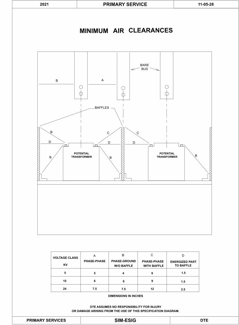
POTENTIAL
TRANSFORMER
DTESIM-ESIG
PRIMARY SERVICE
PRIMARY SERVICES
DTE ASSUMES NO RESPONSIBILITY FOR INJURY
OR DAMAGE ARISING FROM THE USE OF THIS SPECIFICATION DIAGRAM.
2021 11-05-28
TRANSFORMER
POTENTIAL
MINIMUM AIR CLEARANCES
AB
D D
B
A B DC
BB
B
D
C C
BAFFLES
BUS
BARE
DIMENSIONS IN INCHES
VOLTAGE CLASS
KV
PHASE-PHASE PHASE-GROUND
W/O BAFFLE TO BAFFLE
PHASE-PHASE ENERGIZED PART
WITH BAFFLE
55 64
15 9
1.5
6 6 1.5
24 7.5 7.5 2.512

2021 PRIMARY SERVICES 11-6-1
SIM-ESIG
SUBTRANSMISSION POWER SERVICES STPS INSTALLATIONS
1. Purpose
Sub Transmission Power Services are special services provided to economicallysupply secondary electrical loads off the DTE sub transmission grid to offset largeinvestments on distribution line extensions that would be normally required toserve such customer loads, due to current configurations of the DTE distributionsystem.
2. Installation Specifics
Customer loads fed from the Subtransmission Power Service installation aretypically high flicker welding loads or standard power loads that are noteconomically fed from the DTE medium voltage distribution system. Customerservice voltages available are 480Y/277V, or 240V or 480V corner grounded deltasystems. 208/120V, or ungrounded delta 240V or 480V systems are not allowedand are not available. Subtransmission Power Services installations are revenuemetered at the utilization voltage of the service and located at the customer serviceentrance equipment. Fault duty from Subtransmission Power Service installationsare usually high and may require special service entrance equipment to beadequate for installation. Subtransmission Power Services are fed from the 24 or40 kV DTE power grid and require special requirements for customer serviceentrance equipment to meet current Lock-out, Tag-out protection requirements.
3. Subtransmission Power Service Components
The subtransmission line extension on and to the customers property will bedesigned, built, operated and maintained by DTE. The wooden structuresupporting the power transformers, and secondary make-up bus on and to thecustomer’s property will be designed, built, operated and maintained by DTE. Thetransformers on the wooden structure will be installed, connected and maintainedby DTE. The overhead or underground secondary drop to the customer’s riser orrevenue metering enclosure will be provided and connected to the customer riseror revenue metering enclosure. Final connections at the transformer secondarymake-up bus will be by DTE. The revenue metering compartment whether remotefrom, or part of the secondary switchboard, will be provided, installed andmaintained by the customer. The customer service entrance equipment will beprovided, installed and maintained by the customer. DTE Primary Services mustreceive detailed shop drawings and issue approvals on such equipment before it ispurchased or installed. The customer must provide a service entrance ground ringaround the service entrance equipment to meet requirements of DTE PrimaryService Installations.

2021 PRIMARY SERVICES 11-6-2
SIM-ESIG
4. Customer Installation Specifics
(a) Service Drop: The service drop will be composed of either 500 of 750 MCMcopper or aluminum conductors. The insulation of the conductors must beRHW/USE, XLP or jacketed EPR conductors. THHN conductors are not allowed.Overhead drops may be single conductor, bundled or messenger style conductors.All service drop conductors must be approved by Primary Services prior topurchase or installation.
(b) Revenue Metering Enclosure: The revenue metering enclosure whetherremote from or incorporated into the service entrance switchgear will be installedby the customer. The meter enclosure may be a remote CT compartment, but mustbe rated the same as the service entrance main switch or breaker. The revenuemeter compartment must be equipped to install three 600 volt class CT’s and three600 volt class PT’s. The metering transformers will be provided andinstalled by DTE.
5. Service Entrance Equipment
Customer service entrance equipment must be approved by DTE Primary Servicesprior to purchasing and installing. Special requirements are required to interrupthigh fault currents and DTE HEC requirements. Customers will be given the faultduty of the insulation from the DTE customer Account Representative. Thecustomer’s electrical advisor will select the service entrance device and submit thenecessary shop drawings for approval. The service entrance main switch or mainbreaker must meet DTE Primary Services requirements. The main switch or devicemust be one of the three main disconnect devices:
An approved safety switch that allows clear viewing of the open switchblades when the cover is opened for inspection.
A main disconnect switch in a fabricated switchboard that has hinged doorsor a window to view the open switch blades with ease.
A molded case circuit main breaker that has a draw-out mechanism toprovide HEC provisions for circuit maintenance.
Note: Non draw-out molded case circuit breakers and disconnect switches that areunable to show status and clear opening of switchblades are not allowed asservice equipment for Sub Transmission Power Services. Customer ownedmetering and potential devices on the line side of the main switch or circuit breakermust have a open blade knife switch as a secondary disconnecting device. Theknife switch will be installed in an enclosed, labeled compartment with hingeddoors that may be padlocked by a hasp or other captive device. All serviceentrance equipment that is capable of being padlocked must accept a hasp with 33/8-inch shank.

2021 PRIMARY SERVICES 11-6-3
SIM-ESIG
6. Special Customer Services
Subtransmission Power Services usually come with a monthly Rider-2 optionalfacilities charge to cover DTE investment costs of line extension and equipmentinstallation, maintenance and repair considerations. Occasionally when thecustomer has faculties to install and maintain this equipment, the line extensionand transformer structure on the customer’s property may be purchased andinstalled by the customer to reduce the initial investment or Rider-2 monthlycharge. In this case the transmission line, transformers and transformer structurewill be installed, owned and maintained by the customer. All designs for suchservices must have customer solicited engineering drawings and be pre-approvedby DTE Primary Services prior to the start of construction of the project. All DTEHEC requirements for STPS services also stand for customer owned services.

DTE Electric
APPENDIX

5PC894-38Drawing #
APPROVED BY: R. Z. DRAWN BY: B.B.
POT
TRANS
KNIFE SWITCH
OPEN THREE BLADED
GANG OPERATED
FURNISHED BY DTE
VMPHASE-TO-PHASE AND
PHASE-TO-GROUND
QUANTITIES
47-1
51-1
51N-1
52-1
CT'S FOR TRANS-
FORMER DIFFERENTIAL
(IF REQUIRED)
TO SWGR
24 52-2
TO SWGR
CT'S FOR TRANS-
FORMER DIFFERENTIAL
(IF REQUIRED)
51N-2
51-2
QUANTITIES
PHASE-TO-GROUND
PHASE-TO-PHASE AND
VMKNIFE SWITCH
OPEN THREE BLADED
GANG OPERATED
13,200 VOLT WYE-GROUNDED SYSTEM
SCHEMATIC
INCOMING
LINE 1INCOMING
LINE 2
POT TRANS
120V
4800 VOLT DELTA (UNGROUNDED)
POTENTIAL CONNECTION
21 3
43-2 24
b
52-2
b
52-1CS
C
43-1
M
43-1
A
47X-1
86-1
52-1CS
T
43-1
M
86-1
47X-1
A
43-1
G R
BREAKER MECHANISM
86-1
51-1
51N-1
47-1
UV47X-1
47-1
OV
86-1
47X-1
24CS
43-2
BREAKER MECHANISM
86-1
52-2
b
52-1
b
24CS
C
G R
T
43-143-1
M M
86-2
47X-1
43-1
A
52-1
b b
52-2
47X-2
43-1
A
52-2
a
a
52-1
43-2
BREAKER MECHANISM
b
24
86-2
52-1
b
52-2CS
C
43-1
M
47X-2
A
43-1
G R
86-2
86-2
52-2CS
T
43-1
M
86-2
47X-2
43-1
A 51N-2
51-2
47X-2 47-2
OV
47-2
UV47X-2
52-1 24 52-2
REVENUE METERING
43-1 SELECTOR SWITCH - "AUTO-MAN"
43-2 BY-PASS SWITCH - "INTERLOCK-BYPASS"
POSITIONS. (KEY LOCKED PISTOL GRIP SWITCH)
MAINTAINED POSITION. UNDER DTE CONTROL.
47 PHASE SEQUENCE & UNDERVOLTAGE RELAY
47X AUXILLARY RELAY
86 LOCKOUT RELAY
52 BREAKER MECHANISM, OPERATED CONTACT
(OPERATES IN OPERATING POSITION ONLY)
DISCONNECTING CONTACT, CLOSED WHEN DEVICE
IS IN THE CONNECTED POSITION
51 TIME DELAY OVERCURRENT RELAY
51N TIME DELAY NEUTRAL OVERCURRENT RELAY
24 TIE BREAKER
CS BREAKER CONTROL SWITCH
RES RESISTOR
DEVICE FUNCTIONDEVICE
NO.
CONTROL DIAGRAM DEVICES
1. ONLY 2 OF THE 3 CIRCUIT BREAKERS MAY BE CLOSED AT THE SAME TIME.
(EXCEPT SEE NOTE NO. 6)
2. THE INTERLOCK DESCREIBED UNDER 1 MAY BE DEFEATED BY THE SELECTOR SWITCH
43-2. BEFORE USING THE DEVICE 43-2, SELECTOR SWIITCH 43-1 MUST BE TURNED
TO THE "MANUAL" POSITION. DEVICE 43-2 IS KEY OPERATED AND MAY BE LOCKED
(KEY REMOVED) IN EITHER POSITION. THE DEVICE IS UNDER THE CONTROL OF
DTE.
3. NORMAL OPERATION:
52-1 CLOSED
24 OPEN
52-2 CLOSED
4. LOSS OF VOLTAGE ON LINE 1 OPENS 52-1 AND CLOSES 24.
5. LOSS OF VOLTAGE ON LINE 2 OPENS 52-2 AND CLOSES 24.
UNTIL 86-1 OR 86-2 IS RESET.
8. IF 43-1 IS SET FOR AUTOMATIC OPERATION, 52-1, 24, OR 52-2
UNDER VOLTAGE TRANSFER. NORMAL CONDITIONS CAN NOT BE RE-ESTABLISHED
7. OVERCURRENT TRIP OF 52-1 OR 52-2 WILL LOCK OUT AND PREVENT AN
6. RETURN OF VOLTAGE RECLOSES 52-1 OR 52-2 AND OPEN 24.
CAN NOT BE CLOSED OR TRIPPED FROM THIER CONTROL SWITCH.
RETRANSFER IS CLOSED TRANSITION WITHOUT POWER INTERRUPTION,
OPERATION OF AUTOMATIC TRANSFER
TWO LINE AUTOMATIC THROWOVER SCHEME
AM AM
47-2
24 52-2
25
(See Note 1)
NOTE 1: IF SERVICE FEEDS ARE OVERHEAD FED FROM THE DISTRIBUTION
SYSTEM INSTALL A SYNC CHECK RELAY (DEVICE 25).
CHECK WITH PRIMARY SERVICES.
PROVIDED BOTH LINES PHASE. CHECK WITH PRIMARY SERVICES.
25 SYNC CHECK. SEE NOTE 1.
REVENUE METERING
FURNISHED BY DTE
ADDED DEVICE 25
SEP 2003REV.1REV.2REV.3
ALL POTENTIAL TRANSFORMERS ON THE LINE SIDE OF THENOTE 2:
INSTALLED BY CUSTOMER"S CONTRACTOR
INSTALLED BY CUSTOMER"S CONTRACTOR
MAIN BREAKER REQUIRE A GANG OPERATED OPEN KNIFE
BLADE SWITCH ON THE SECONDARY AS SHOWN ABOVE.
(SEE NOTE 2) (SEE NOTE 2)
PRIMARY SERVICES
RES
RES
ELECTRICAL INTERLOCKS ARE TO BE HARD WIRED BREAKERNOTE 3:
CONTACTS AND NOT VIA INTERPOSING RELAYS.
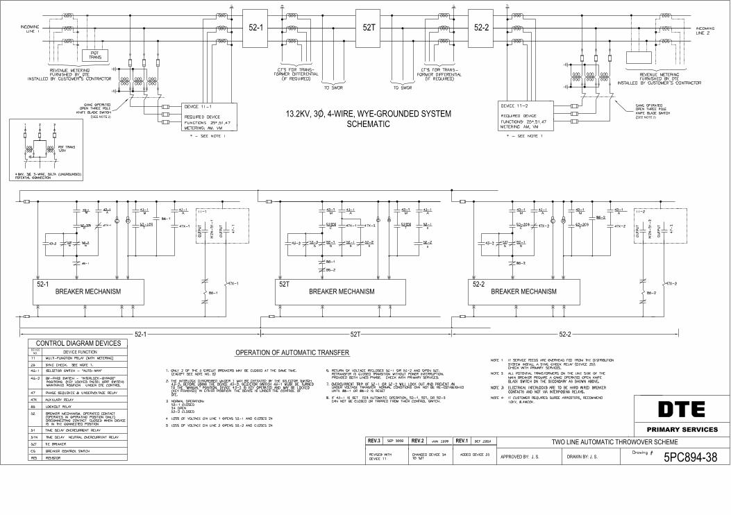
5PC894-38Drawing #
APPROVED BY: J. S. DRAWN BY: J. S.
POT
TRANS
FURNISHED BY DTE
52-1
CT'S FOR TRANS-
FORMER DIFFERENTIAL
(IF REQUIRED)
TO SWGR
52T 52-2
TO SWGR
CT'S FOR TRANS-
FORMER DIFFERENTIAL
(IF REQUIRED)
13.2KV, 3O, 4-WIRE, WYE-GROUNDED SYSTEM
SCHEMATIC
INCOMING
LINE 1INCOMING
LINE 2
POT TRANS
120V
4.8KV, 3O, 3-WIRE, DELTA (UNGROUNDED)
POTENTIAL CONNECTION
21 3
43-2 52T
b
52-2
b
52-1CS
C
43-1
M
43-1
A
47X-1
86-1
52-1CS
T
43-1
M
86-1
47X-1
A
43-1
G R
BREAKER MECHANISM 86-1
47X-1
52TCS
43-2
BREAKER MECHANISM
86-1
52-2
b
52-1
b
52TCS
C
G R
T
43-143-1
M M
86-2
47X-1
43-1
A
52-1
b b
52-2
47X-2
43-1
A
52-2
a
a
52-1
43-2
BREAKER MECHANISM
b
52T
86-2
52-1
b
52-2CS
C
43-1
M
47X-2
A
43-1
G R52-2CS
T
43-1
M
86-2
47X-2
43-1
A
52-1 52T 52-2
REVENUE METERING
43-1 SELECTOR SWITCH - "AUTO-MAN"
43-2 BY-PASS SWITCH - "INTERLOCK-BYPASS"
POSITIONS. (KEY LOCKED PISTOL GRIP SWITCH)
MAINTAINED POSITION. UNDER DTE CONTROL.
47 PHASE SEQUENCE & UNDERVOLTAGE RELAY
47X AUXILLARY RELAY
86 LOCKOUT RELAY
52 BREAKER MECHANISM, OPERATED CONTACT
(OPERATES IN OPERATING POSITION ONLY)
DISCONNECTING CONTACT, CLOSED WHEN DEVICE
IS IN THE CONNECTED POSITION
51 TIME DELAY OVERCURRENT RELAY
51N TIME DELAY NEUTRAL OVERCURRENT RELAY
52T TIE BREAKER
CS BREAKER CONTROL SWITCH
RES RESISTOR
DEVICE FUNCTIONDEVICE
NO.
CONTROL DIAGRAM DEVICES
1. ONLY 2 OF THE 3 CIRCUIT BREAKERS MAY BE CLOSED AT THE SAME TIME.
(EXCEPT SEE NOTE NO. 6)
2. THE INTERLOCK DESCREIBED UNDER 1 MAY BE DEFEATED BY THE SELECTOR SWITCH
43-2. BEFORE USING THE DEVICE 43-2, SELECTOR SWIITCH 43-1 MUST BE TURNED
TO THE "MANUAL" POSITION. DEVICE 43-2 IS KEY OPERATED AND MAY BE LOCKED
(KEY REMOVED) IN EITHER POSITION. THE DEVICE IS UNDER THE CONTROL OF
DTE.
3. NORMAL OPERATION:
52-1 CLOSED
24 OPEN
52-2 CLOSED
4. LOSS OF VOLTAGE ON LINE 1 OPENS 52-1 AND CLOSES 24.
5. LOSS OF VOLTAGE ON LINE 2 OPENS 52-2 AND CLOSES 24.
UNTIL 86-1 OR 86-2 IS RESET.
8. IF 43-1 IS SET FOR AUTOMATIC OPERATION, 52-1, 52T, OR 52-2
UNDER VOLTAGE TRANSFER. NORMAL CONDITIONS CAN NOT BE RE-ESTABLISHED
7. OVERCURRENT TRIP OF 52-1 OR 52-2 WILL LOCK OUT AND PREVENT AN
6. RETURN OF VOLTAGE RECLOSES 52-1 OR 52-2 AND OPEN 52T.
CAN NOT BE CLOSED OR TRIPPED FROM THIER CONTROL SWITCH.
RETRANSFER IS CLOSED TRANSITION WITHOUT POWER INTERRUPTION,
OPERATION OF AUTOMATIC TRANSFER
TWO LINE AUTOMATIC THROWOVER SCHEME
52T 52-2
NOTE 1: IF SERVICE FEEDS ARE OVERHEAD FED FROM THE DISTRIBUTION
SYSTEM INSTALL A SYNC CHECK RELAY (DEVICE 25).
CHECK WITH PRIMARY SERVICES.
PROVIDED BOTH LINES PHASE. CHECK WITH PRIMARY SERVICES.
25 SYNC CHECK. SEE NOTE 1.
REVENUE METERING
FURNISHED BY DTE
ADDED DEVICE 25
SEP 2003REV.1REV.2REV.3
ALL POTENTIAL TRANSFORMERS ON THE LINE SIDE OF THENOTE 2:
INSTALLED BY CUSTOMER"S CONTRACTOR
INSTALLED BY CUSTOMER"S CONTRACTOR
MAIN BREAKER REQUIRE A GANG OPERATED OPEN KNIFE
BLADE SWITCH ON THE SECONDARY AS SHOWN ABOVE.
(SEE NOTE 2)
PRIMARY SERVICES
ELECTRICAL INTERLOCKS ARE TO BE HARD WIRED BREAKERNOTE 3:
CONTACTS AND NOT VIA INTERPOSING RELAYS.
JUN 2009
CHANGED DEVICE 24
TO 52T
REQUIRED DEVICE
FUNCTIONS: 25*,51,47
METERING: AM, VM
GANG OPERATED
OPEN THREE POLE
KNIFE BLADE SWITCH
(SEE NOTE 2)
GANG OPERATED
OPEN THREE POLE
KNIFE BLADE SWITCH
IF CUSTOMER REQUIRES SURGE ARRESTERS, RECOMMENDNOTE 4:
10KV, 8.4MCOV.
XY
ZN
-51-1
47
-1
DEVICE 11-1
REQUIRED DEVICE
FUNCTIONS: 25*,51,47
METERING: AM, VM
DEVICE 11-2
11 MULTI-FUNCTION RELAY (WITH METERING)
11-1
SEP 2009
REVISED WITH
DEVICE 11
86-2
47X-2
XY
ZN
-51-2
47
-2
11-2
* - SEE NOTE 1 * - SEE NOTE 1
OU
TP
UT
OU
TP
UT
OU
TP
UT
OU
TP
UT
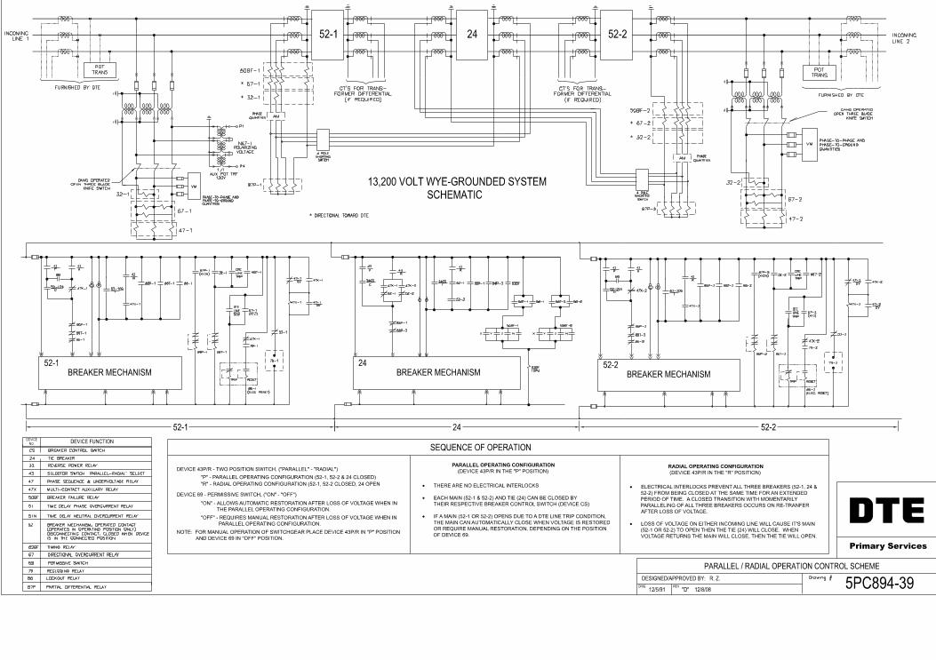
5PC894-39Drawing #DESIGNED/APPROVED BY: R. Z.
POT
TRANS
KNIFE SWITCH
OPEN THREE BLADE
GANG OPERATED
FURNISHED BY DTE
VM
PHASE-TO-PHASE AND
PHASE-TO-GROUND
QUANTITIES
47-1
50BF-1
52-1
CT'S FOR TRANS-
FORMER DIFFERENTIAL
(IF REQUIRED)
24 52-2
CT'S FOR TRANS-
FORMER DIFFERENTIAL
(IF REQUIRED)
QUANTITIES
PHASE-TO-GROUND
PHASE-TO-PHASE AND
VM
KNIFE SWITCH
OPEN THREE BLADE
GANG OPERATED
13,200 VOLT WYE-GROUNDED SYSTEM
SCHEMATIC
INCOMING
LINE 1INCOMING
LINE 2
86-1
52-1CS
T
86P-1
47X-1
R
43
G R
BREAKER MECHANISM
87P-1
(XYZN)
47-1
UV47X-1
47-1
OV
86P-1
47X-1
24CS
BREAKER MECHANISM
86P-1
24CS
C
G R
T
43
P
86P-2
43
R
43
R
52-2
52-1
52-1 24
FURNISHED BY DTE
43 SELECTOR SWITCH "PARALLEL-RADIAL" SELECT
47 PHASE SEQUENCE & UNDERVOLTAGE RELAY
47X MULTI-CONTACT AUXILLARY RELAY
86 LOCKOUT RELAY
52 BREAKER MECHANISM, OPERATED CONTACT
(OPERATES IN OPERATING POSITION ONLY)
DISCONNECTING CONTACT, CLOSED WHEN DEVICE
IS IN THE CONNECTED POSITION
51 TIME DELAY PHASE OVERCURRENT RELAY
51N TIME DELAY NEUTRAL OVERCURRENT RELAY
24 TIE BREAKER
CS BREAKER CONTROL SWITCH
DEVICE FUNCTIONDEVICE
NO.
SEQUENCE OF OPERATION
PARALLEL / RADIAL OPERATION CONTROL SCHEME
43
P
43
R
47X-152-1CS
C
52-2
TRANS
POT
79 RECLOSING RELAY
86T-1
86P-1
86T-1 86-1
6932-1
86T-1
DTE
LINE
TRIP
N67-1
TRIP RESET
LINE
TRIP
DTE
67-1
(XYZ)
79-1
47X-1
79-1
52-1
47X-1 47X-2
52-1 52-2
86P-1 86P-2 62BF
86T-1 86-1
X Y Z N
50BF-1
X Y Z N
50BF-2
86-286T-2
62BF
TDPU
BREAKER MECHANISM
52-2
86P-2
86T-2
86-2
47X-2
(XYZ)
67-2
RESET
86P-2
TRIP
86T-2
TRIP
LINE
DTE
79-2
79-2
52-2
47X-2
47X-2 47-2
OV
69
52-2CS
C
P
43
47X-2G R
R
43
43
52-2CS
T
R
86P-2 86T-2
(XYZN)
86-2
87P-2LINE
TRIP
32-2
DTE
N67-2
47-2
UV47X-2
86-2
(ELEC. RESET)
86-1
(ELEC. RESET)
67-1
32-1
P1
P4
N67-1
POLARIZING
VOLTAGE
1/1
AUX POT TRF
120V
* 67-1
* 32-1
AM
87P-1
4 POLE
SHORTING
SWITCH
* DIRECTIONAL TOWARD DTE47-2
67-2
32-2
SWITCH
SHORTING
4 POLE
87P-2
* 32-2
* 67-2
50BF-2
32 REVERSE POWER RELAY
Primary Services
69 PERMISSIVE SWITCH
50BF BREAKER FAILURE RELAY
67 DIRECTIONAL OVERCURRENT RELAY
87P PARTIAL DIFFERENTIAL RELAY
DEVICE 43P/R - TWO POSITION SWITCH, ("PARALLEL" - "RADIAL")
"P" - PARALLEL OPERATING CONFIGURATION (52-1, 52-2 & 24 CLOSED)
"R" - RADIAL OPERATING CONFIGURATION (52-1, 52-2 CLOSED, 24 OPEN
DEVICE 69 - PERMISSIVE SWITCH, ("ON" - "OFF")
THE PARALLEL OPERATING CONFIGURATION.
"ON" - ALLOWS AUTOMATIC RESTORATION AFTER LOSS OF VOLTAGE WHEN IN
PARALLEL OPERATING CONFIGURATION.
"OFF" - REQUIRES MANUAL RESTORATION AFTER LOSS OF VOLTAGE WHEN IN
AND DEVICE 69 IN "OFF" POSITION.
NOTE: FOR MANUAL OPERATION OF SWITCHGEAR PLACE DEVICE 43P/R IN "P" POSITION
(DEVICE 43P/R IN THE "P" POSITION)
PARALLEL OPERATING CONFIGURATION
OF DEVICE 69.
OR REQUIRE MANUAL RESTORATION, DEPENDING ON THE POSITION
THE MAIN CAN AUTOMATICALLY CLOSE WHEN VOLTAGE IS RESTORED
IF A MAIN (52-1 OR 52-2) OPENS DUE TO A DTE LINE TRIP CONDITION,·
THEIR RESPECTIVE BREAKER CONTROL SWITCH (DEVICE CS)
EACH MAIN (52-1 & 52-2) AND TIE (24) CAN BE CLOSED BY ·
THERE ARE NO ELECTRICAL INTERLOCKS·
(DEVICE 43P/R IN THE "R" POSITION)
RADIAL OPERATING CONFIGURATION
VOLTAGE RETURNS THE MAIN WILL CLOSE, THEN THE TIE WILL OPEN.
(52-1 OR 52-2) TO OPEN THEN THE TIE (24) WILL CLOSE. WHEN
LOSS OF VOLTAGE ON EITHER INCOMING LINE WILL CAUSE IT'S MAIN ·
AFTER LOSS OF VOLTAGE.
PARALLELING OF ALL THREE BREAKERS OCCURS ON RE-TRANFER
PERIOD OF TIME. A CLOSED TRANSITION WITH MOMENTARILY
52-2) FROM BEING CLOSED AT THE SAME TIME FOR AN EXTENDED
ELECTRICAL INTERLOCKS PREVENT ALL THREE BREAKERS (52-1, 24 & ·
ORIG
12/5/91REV
"D" 12/8/08
PHASE
QUANTITIES
AMPHASE
QUANTITIES
62BF TIMING RELAY

43B
43
M
52-1
CS
52-2
86-1
43
A
43S
1
47X-1
43S
2
47X-1
47X-2
CLOSE
52-2
2
43S
47X-1
A
43
86-1
43
M
52-1
CS
CLOSE
47X-2
47X-1
1
43S
47X-2
2
43S
A
43
86-2
52-1
CS
52-2
M
43
43B
TRIP TRIP
CS
52-2
M
43
86-2
43
A
47X-2
43S
1
52-1
LINE 1 LINE 2
52-1 52-2
52-1 52-2
PARTIAL SCHEMATIC - ATO SCHEME (NORMAL-ALTERNATE) W/ NORMAL LINE SELECTION
43 - MANUAL/AUTOMATIC SELECTOR SWITCH, TWO POSITION "MAN" & "AUTO"
43B - BYPASS SWITCH, TWO POSITION "NORMAL" & "BYPASS", KEYED (OPERATED BY DTE PERSONNEL ONLY)
43S - LINE SELECTOR SWITCH, TWO POSITION "LINE 1" & "LINE 2", KEYED (OPERATED BY DTE PERSONNEL ONLY)
LINE 1 - LINE 1 NORMAL, LINE 2 ALTERNATE
LINE 2 - LINE 2 NORMAL, LINE 1 ALTERNATE
APPROVED BY: R. Z. REVISION DATE:
86-2 86-1
12-10-05
52-2 52-1
Drawing #
DESIGNED BY: R. Z.
CLOSED TRANSITION ON GO-BACK
Primary Services
25 - SYNC. CHECK RELAY, RECOMMENDED WHEN SERVICE IS VIA AN OVERHEAD LINE ON THE DISTRIBUTION SYSTEM.
CONSULT WITH DTE'S PRIMARY SERVICES GROUP.
PC894-40
*
*
25
52-1
25
52-2*
* *
*


120V AC
24V AC
94
RCU (BY DECO)94X
94
94X
94X
94X
94
62
86 (ELECT RESET)
2PDT
TOGGLE
SWITCH
ALARM
RESET
TRIP
5294X
NOTE:
1 86 IS NOT ACCESSABLE TO CUSTOMER
2 RCU-CONTACT IS NORMALLY CLOSED
RECIEPT OF INTERRUPT SIGNAL OPENS CONTACT AND STARTS
20 MINUTE TIMER INTERNAL TO RCU. DECO WILL SEND AN
INTERRUPT SIGNAL EVERY 15 MINUTES FOR THE DURATION OF
THE INTERRUPTION, AFTER WHICH TIME THE TIMER WILL TIME
OUT AND CLOSE THE CONTACT.
3. WIRE DEVICE 86 "a" CONTACT IN TRIP STRING, & "b" CONTACT IN CLOSE STRING
DRAWING
PC894-42DETROIT EDISON-PRIMARY SERVICES
52
62 (T.D.P.U.-20 MIN.)
INTERRUPTABLE SERVICE (RATE D3.3)

APPROVED BY: RELAY ENGINEERING:JUNE 2001 5PC894-43Drawing #DESIGNED/APPROVED BY: R. Z. (Primary Service)
POT
TRANS
KNIFE SWITCH
OPEN THREE BLADED
GANG OPERATED
FURNISHED BY DTE
VM
PHASE-TO-PHASE AND
PHASE-TO-GROUND
QUANTITIES
47-1
51-1
51N-1
52-1
CT'S FOR TRANS-
FORMER DIFFERENTIAL
(IF REQUIRED)
LOAD
24 52-2
LOAD
CT'S FOR TRANS-
FORMER DIFFERENTIAL
(IF REQUIRED)
51N-2
51-2
QUANTITIES
PHASE-TO-GROUND
PHASE-TO-PHASE AND
VMKNIFE SWITCH
OPEN THREE BLADED
GANG OPERATED
13,200 VOLT WYE-GROUNDED SYSTEM
SCHEMATIC
INCOMING
LINE 1INCOMING
LINE 2
POT TRANS
120V
4800 VOLT DELTA (UNGROUNDED)
POTENTIAL CONNECTION
21 3
43B24
b52-2
b
86-1
52-1CS
C
43
M
86-1
47X-1
A
43
G R
BREAKER MECHANISM
86-1
51-1
51N-1
47-1
UV47X-1
47-1
OV
86-1
47X-124CS
43B
BREAKER MECHANISM
86-1
52-2
b
52-1
b
24CS
C
G R
T
4343
M M
86-2
47X-1
43
A
52-1
b b
52-2
47X-2
43
A
52-2
a
a
52-1
43B
BREAKER MECHANISM
b
24
86-2
52-1
b
52-2CS
C
43
M
G
R
86-2
86-2
52-2CS
C
43
M
86-2
47X-2
43
A 51N-2
51-2
47x-2 47-2
OV
47-2
UV47X-2
52-1 24 52-2
FURNISHED BY DTE
52-1 24
43 SELECTOR SWITCH "AUTO-MAN-LINE SELECT"
43B BY-PASS SWITCH "INTERLOCK - BYPASS"
POSITIONS. (KEY LOCKED PISTOL GRIP SWITCH)
MAINTAINED POSITION, UNDER DTE CONTROL.
47 PHASE SEQUENCE & UNDERVOLTAGE RELAY
47X MULTI-CONTACT AUXILLARY RELAY
86 LOCKOUT RELAY
52 BREAKER MECHANISM, OPERATED CONTACT
(OPERATES IN OPERATING POSITION ONLY)
DISCONNECTING CONTACT, CLOSED WHEN DEVICE
IS IN THE CONNECTED POSITION
51 TIME DELAY PHASE OVERCURRENT RELAY
51N TIME DELAY NEUTRAL OVERCURRENT RELAY
24 TIE BREAKER
CS BREAKER CONTROL SWITCH
DEVICE FUNCTIONDEVICE
NO.
CONTROL DIAGRAM DEVICES
DEVICE 43 - THREE POSITION SWITCH, "AUTO-MAN-BEST LINE".
MODE OF OPERATION
TWO LINE AUTOMATIC THROWOVER & LINE SELECT AUTOMATIC THROWOVER SCHEME
43
M
43
A
47X-1
52-1CS
C86-2
43
LS
43S
1
43S
2
47X-1
47X-2
b
52-2
43
LS
a
52-2
43
LS
43S
2
"MAN" POSITION:
"AUTO" POSITION:
AUTOMATIC OPERATION OF 52-1, 24 and 52-2
MANUAL OPERATION OF 52-1, 24 AND 52-2
NORMAL: 52-1 and 52-2 CLOSED, 24 OPEN
UPON LOW OR LOSS OF VOLTAGE TO LINE 1 (LINE 2),
UPON RETURN OF VOLTAGE TO LINE1 (LINE 2),
(NOTE: CLOSED TRANSITION ON THROWBACK)
"LINE SELECT" POSITION:
PROVIDES ONE NORMAL LOAD CARRYING LINE AND ONE ALTERNATE LINE.
DEVICE 43S - TWO POSITION SWITCH, "LINE 1 - LINE 2", KEYED.
(NOTE: KEY IS UNDER DTE CONTROL)
VIA BREAKER CONTROL SWITCH (DEVICE 52/CS).
52-1 (52-2) WILL OPEN, THEN 24 WILL CLOSE.
52-1 (52-1) WILL CLOSE, THEN 24 WILL OPEN.
NORMAL: EITHER
43S "LINE 1" - 52-1 AND 24 CLOSED WITH 52-2 OPEN.
OR
43S "LINE 2" - 52-2 AND 24 CLOSED WITH 52-1 OPEN.
UPON LOW OR LOSS OF VOLTAGE ON LINE 1 ( LINE 2),
52-1 (52-2) WILL OPEN, THEN 52-2 (52-1) WILL CLOSE.
52-1 (52-2) WILL CLOSE, THEN 52-2 (52-1) WILL OPEN.
UPON RETURN OF VOLTAGE ON LINE 1 ( LINE 2),
43S SELECTOR SWITCH "LINE 1 - LINE 2"
POSITIONS. (KEY LOCKED PISTOL GRIP SWITCH)
MAINTAINED POSITION, UNDER DTE CONTROL.
DEVICE 43B- TWO POSITION SWITCH, "INTERLOCK - BYPASS".
ALLOWS DTE TO CLOSE 52-1, 24 AND 52-2 AT SOME TIME.
(NOTE: KEY IS UNDER DTE CONTROL)
43S
LS
43S
2
74-1 74-1
ALARM
ON LOSS
OF
ALTERNATE
SOURCE
43
LS
47X-2 47X-1
b
52-1
43S
2
47X-2
43S
1
43
A
86-1
43
LS
43
LS
1
43S
43
LS
52-1
a
SOURCE
ALARM
ON LOSS
ALTERNATE
OF
74-2 74-2
43S
1
43S
LS
52-2
TRANS
POT
47X-1
74-1 74-2
47X-2
74 ALARM RELAY
AM AM
47-2
86-1
86-2
Primary Services
REV DATE