Embed Size (px)
Citation preview
SERVICE GUIDE
Virgin Orbit, LLC / Version 1.0 / 7 August 2017Cleared for Release: 17-S-2156.
VIR
GIN
OR
BIT
LA
UN
CH
ERO
NE
SER
VIC
E G
UID
E V
1.0
1
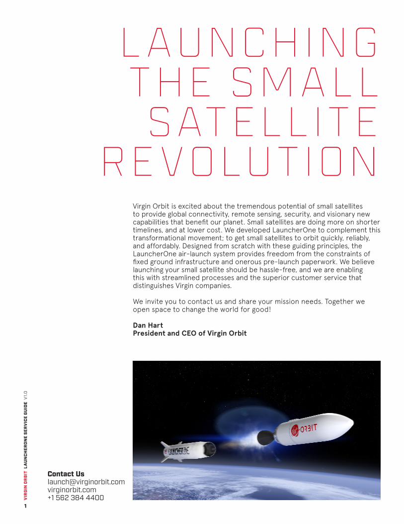
Launching the Small Satellite
RevolutionVirgin Orbit is excited about the tremendous potential of small satellites to provide global connectivity, remote sensing, security, and visionary new capabilities that benefit our planet. Small satellites are doing more on shorter timelines, and at lower cost. We developed LauncherOne to complement this transformational movement; to get small satellites to orbit quickly, reliably, and affordably. Designed from scratch with these guiding principles, the LauncherOne air-launch system provides freedom from the constraints of fixed ground infrastructure and onerous pre-launch paperwork. We believe launching your small satellite should be hassle-free, and we are enabling this with streamlined processes and the superior customer service that distinguishes Virgin companies.
We invite you to contact us and share your mission needs. Together we open space to change the world for good!
Dan HartPresident and CEO of Virgin Orbit
Contact Us [email protected] virginorbit.com +1 562 384 4400
VIR
GIN
OR
BIT
LA
UN
CH
ERO
NE
SER
VIC
E G
UID
E V
1.0
2
CONTENTS
1/ THE VIRGIN ORBIT EXPERIENCE 3
1.1 Capabilities at a Glance 6
2/ DESIGN YOUR MISSION 7
2.1 Payload Delivery Capability 82.2 Orbit Insertion Accuracy 92.3 Payload Accommodations 102.4 Supported Separation Systems 11
3/ THE ORBIT VIRGIN LAUNCH SERVICE PROCESS 13
3.1 Launch Service Elements 143.2 Launch Service Schedule 153.3 Customer Responsibilities 153.4 Safety and Mission Assurance 16
4/ PAYLOAD PROCESSING AND LAUNCH OPERATIONS 174.1 Payload Processing Facilities 184.2 Payload Processing Flow 194.3 Launch Locations 204.4 Launch Operations Flow 20
5/ PAYLOAD ENVIRONMENTS 21
5.1 Vehicle Coordinate System 225.2 Payload Constraints 225.3 Acceleration from Quasi-Static Loads 235.4 Shock Environment 235.5 Random Vibration 245.6 Acoustics 255.7 Payload Radio Frequency (RF) Constraints and Environment 265.8 Thermal and Humidity Environment 275.9 Fairing Pressure Environment 275.10 Separation System Signal 275.11 Spacecraft Electrical Interface 27
6/ ABOUT VIRGIN ORBIT 29
6.1 Corporate Overview 306.2 Launch Vehicle Production and Test Facilities 316.3 Spaceport Facilities 32
7/ DOCUMENT REFERENCE 33
7.1 List of Acronyms 347.2 List of Tables 347.3 List of Figures 35

VIR
GIN
OR
BIT
LA
UN
CH
ERO
NE
SER
VIC
E G
UID
E V
1.0
3
1 TheVirgin Orbit
Experience

VIR
GIN
OR
BIT
LA
UN
CH
ERO
NE
SER
VIC
E G
UID
E V
1.0
4
THE VIRGIN ORBIT EXPERIENCE
The rapidly growing small satellite industry requires a launch service that is equally agile, flexible, and affordable. Virgin Orbit’s launch vehicle, LauncherOne, is the result of our investment in the team, technologies, and facilities required to build a customer-focused launch service.
LauncherOne is Your Ride to Space
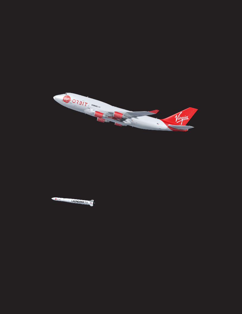
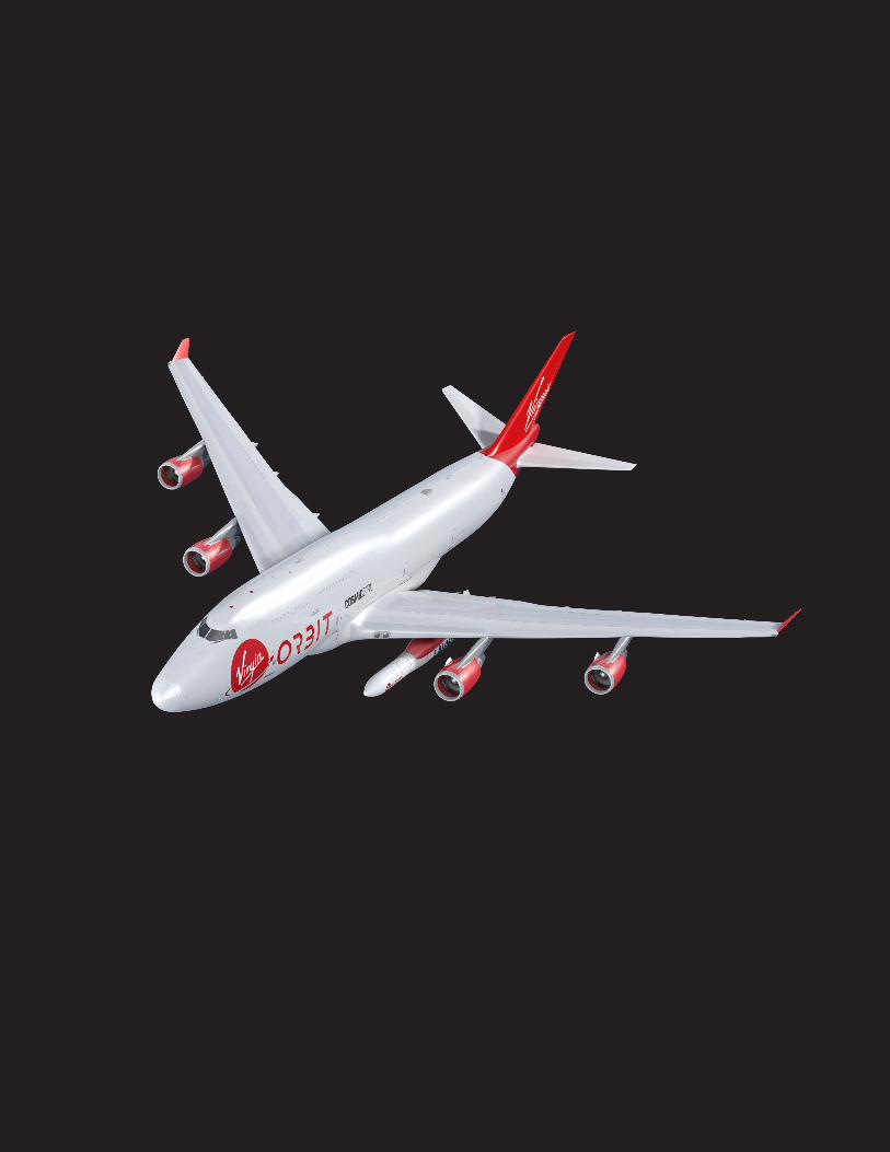
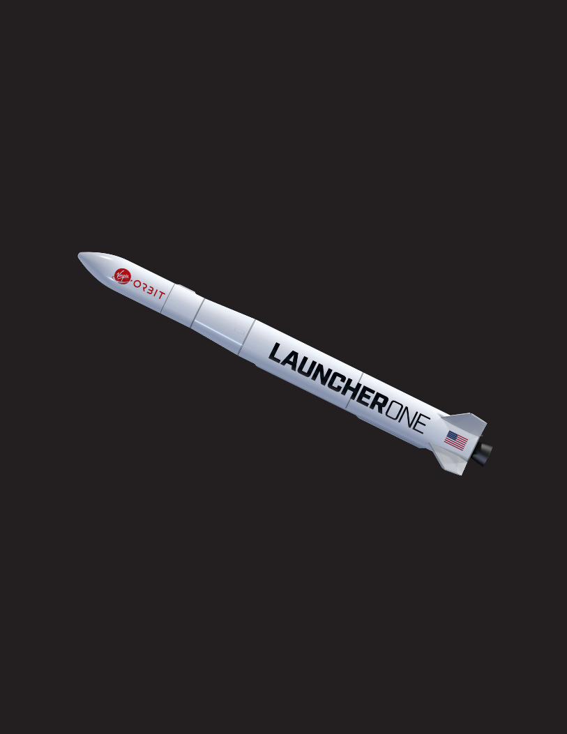
LauncherOne is a simple, expendable, launch vehicle designed to place small satellites of up to 500 kg / 1100 lbm into a wide range of Low Earth Orbits (LEO) at an affordable price. Rather than launching from ground level, LauncherOne is carried to an altitude of approximately 35,000 feet by the 747-400 carrier aircraft, Cosmic Girl, as depicted in FIGURE 1.
The simple design of LauncherOne increases reliability while keeping costs low. In order to balance performance with commercially-competitive pricing, LauncherOne was designed through a “clean-sheet” design process, in which all potential vehicle configurations were traded against each other (different numbers of stages, various propulsion types, etc.). Throughout LauncherOne’s design, the Virgin Orbit team actively rejected complexity, favoring a straightforward and reliable design. This avoids the common trap of incurring significant cost increases for only a marginal increase in performance.
FIGURE 1/ LAUNCHERONE SYSTEM EXPANDED VIEW
1
VIR
GIN
OR
BIT
LA
UN
CH
ERO
NE
SER
VIC
E G
UID
E V
1.0
5
Your Orbit on Your Schedule
Orbit offerings to any orbit inclination on as short as 6 month lead time.
Air-launch eliminates much of the compulsory overhead of ground launched systems, and provides unprecedented flexibility in launch operations. By operating independently from national launch ranges, LauncherOne avoids common causes of launch delays such as logjams in the launch queue, weather, unavailable radar tracking assets, and boats in the launch pad stay-out zone. The carrier aircraft serves as a mobile launch platform, offering custom launch solutions not traditionally available to small satellites, including tremendous flexibility in the spaceport of origin, orbital destination, and launch date.
Class Leading Payload Flexibility
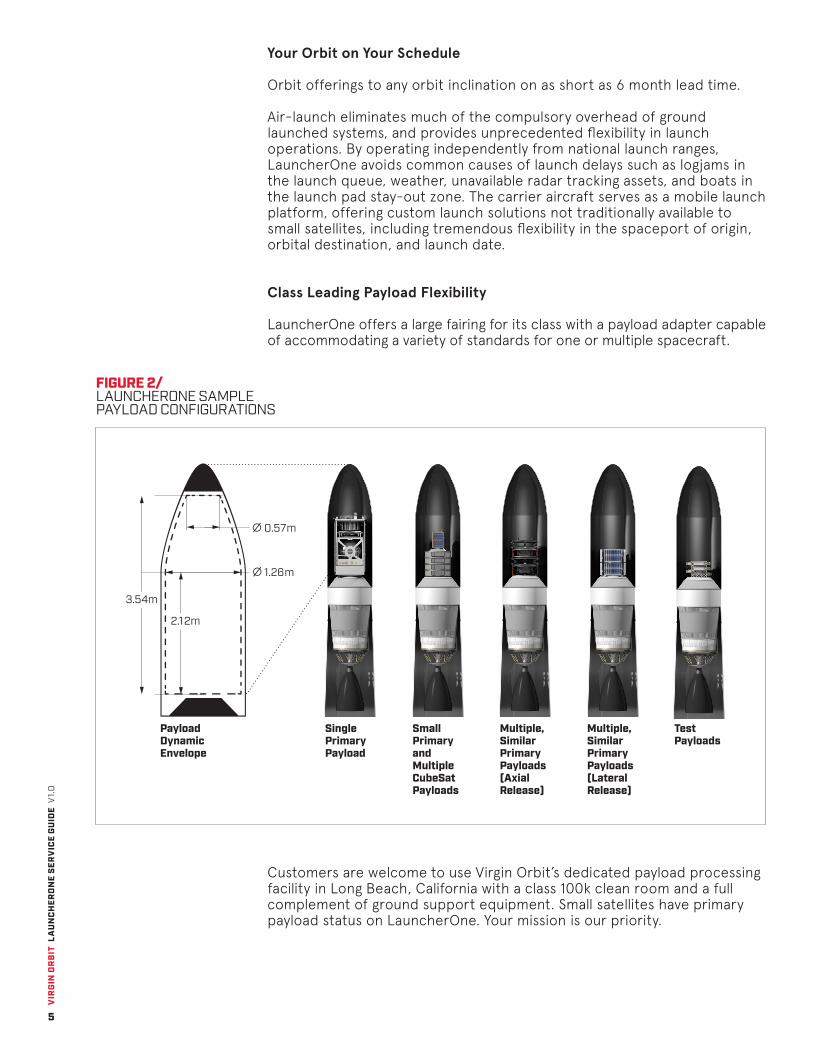
LauncherOne offers a large fairing for its class with a payload adapter capable of accommodating a variety of standards for one or multiple spacecraft.
FIGURE 2/ LAUNCHERONE SAMPLE PAYLOAD CONFIGURATIONS
Single Primary Payload
0.57m
1.26m
Payload Dynamic Envelope
Small Primary and Multiple CubeSat Payloads
Multiple, SimilarPrimary Payloads(Axial Release)
Multiple, SimilarPrimary Payloads(Lateral Release)
Test Payloads
3.54m
2.12m
Customers are welcome to use Virgin Orbit’s dedicated payload processing facility in Long Beach, California with a class 100k clean room and a full complement of ground support equipment. Small satellites have primary payload status on LauncherOne. Your mission is our priority.
VIR
GIN
OR
BIT
LA
UN
CH
ERO
NE
SER
VIC
E G
UID
E V
1.0
6
Bringing the Virgin Experience to Space Launch
As a member of the Virgin family, Virgin Orbit aims to extend the world renowned Virgin customer service to the space launch industry, placing particular emphasis on the value that our dedicated and spirited team of engineers can add to your launch experience. To accomplish this we are improving the overall experience of getting to orbit, by streamlining the processes leading up to launch and emphasizing customer satisfaction.
This document is intended as a launch planning resource, and more detailed, mission specific information is available upon request. After a Launch Services Agreement is executed, a Mission Manager is assigned to each customer to assist in all aspects of the mission. Please do not hesitate to contact us with questions or special accommodation requests.
CAPABILITIES AT A GLANCE
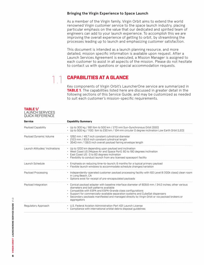
Key components of Virgin Orbit’s LauncherOne service are summarized in TABLE 1. The capabilities listed here are discussed in greater detail in the following sections of this Service Guide, and may be customized as needed to suit each customer’s mission-specific requirements.
TABLE 1/ LAUNCH SERVICES QUICK REFERENCE
1.1
Service
Payload Capability
Payload Dynamic Volume
Launch Altitudes/ Inclinations
Launch Schedule
Payload Processing
Payload Integration
Regulatory Approach
Capability Summary
• Up to 300 kg / 661 lbm to 500 km / 270 nmi Sun-Synchronous Orbit (SSO)• Up to 500 kg / 1100 lbm to 230 km / 124 nmi circular 0 degree inclination Low Earth Orbit (LEO)
• 1262 mm / 49.7 inch constant cylindrical diameter• 2123 mm / 83.6 inch constant cylindrical length• 3543 mm / 139.5 inch overall payload fairing envelope length
• Up to 1200 km depending upon payload and inclination• West Coast US (Mojave Air and Space Port): 60 to 180 degrees inclination• East Coast US : 0 to 60 degrees inclination• Flexibility to conduct launch from any licensed spaceport facility
• Emphasis on reducing time-to-launch; 6 months for a typical primary payload• Flexible launch windows to accommodate schedule changes/variation
• Independently-operated customer payload processing facility with ISO Level 8 (100k class) clean room in Long Beach, CA
• Options exist for receipt of pre-encapsulated payloads
• Conical payload adapter with baseline interface diameter of 609.6 mm / 24.0 inches; other various diameters and bolt patterns available
• Compatible with ESPA and ESPA-Grande class configurations• Support for commercially-available separation systems and CubeSat dispensers• Secondary payloads manifested and managed directly by Virgin Orbit or via payload brokers or
aggregators
• U.S. Federal Aviation Administration Part 431 Launch License• Compliance with international orbital debris disposal guidelines

VIR
GIN
OR
BIT
LA
UN
CH
ERO
NE
SER
VIC
E G
UID
E V
1.0
7
2Design Your
Mission
VIR
GIN
OR
BIT
LA
UN
CH
ERO
NE
SER
VIC
E G
UID
E V
1.0
8
DESIGN YOUR MISSIONLet us get you to where you want to go. LauncherOne’s air-launch architecture enables unparalleled flexibility in orbital definition. We even have the capability to efficiently deliver payloads to inclinations as low as 0-degree equatorial orbit.
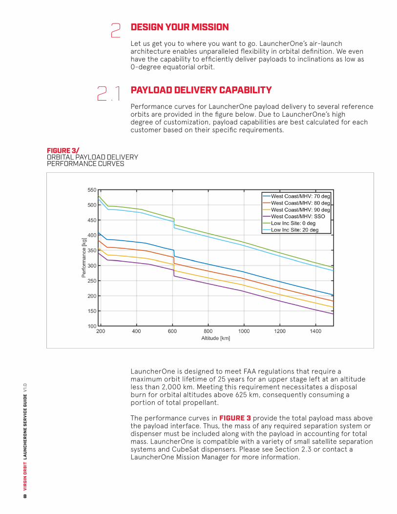
PAYLOAD DELIVERY CAPABILITYPerformance curves for LauncherOne payload delivery to several reference orbits are provided in the figure below. Due to LauncherOne’s high degree of customization, payload capabilities are best calculated for each customer based on their specific requirements.
FIGURE 3/ ORBITAL PAYLOAD DELIVERY PERFORMANCE CURVES
2
2.1
LauncherOne is designed to meet FAA regulations that require a maximum orbit lifetime of 25 years for an upper stage left at an altitude less than 2,000 km. Meeting this requirement necessitates a disposal burn for orbital altitudes above 625 km, consequently consuming a portion of total propellant.
The performance curves in FIGURE 3 provide the total payload mass above the payload interface. Thus, the mass of any required separation system or dispenser must be included along with the payload in accounting for total mass. LauncherOne is compatible with a variety of small satellite separation systems and CubeSat dispensers. Please see Section 2.3 or contact a LauncherOne Mission Manager for more information.
VIR
GIN
OR
BIT
LA
UN
CH
ERO
NE
SER
VIC
E G
UID
E V
1.0
9
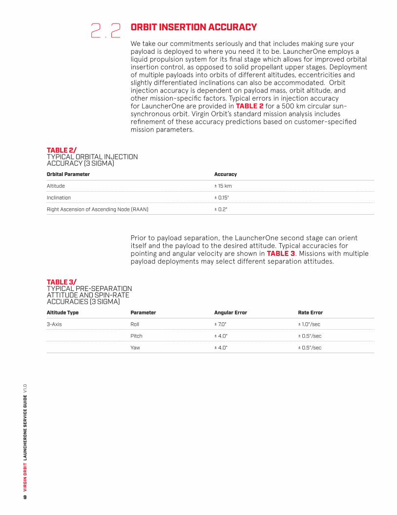
ORBIT INSERTION ACCURACY We take our commitments seriously and that includes making sure your payload is deployed to where you need it to be. LauncherOne employs a liquid propulsion system for its final stage which allows for improved orbital insertion control, as opposed to solid propellant upper stages. Deployment of multiple payloads into orbits of different altitudes, eccentricities and slightly differentiated inclinations can also be accommodated. Orbit injection accuracy is dependent on payload mass, orbit altitude, and other mission-specific factors. Typical errors in injection accuracy for LauncherOne are provided in TABLE 2 for a 500 km circular sun-synchronous orbit. Virgin Orbit’s standard mission analysis includes refinement of these accuracy predictions based on customer-specified mission parameters.
TABLE 2/ TYPICAL ORBITAL INJECTION ACCURACY (3 SIGMA)
TABLE 3/ TYPICAL PRE-SEPARATION ATTITUDE AND SPIN-RATE ACCURACIES (3 SIGMA)
2.2
Prior to payload separation, the LauncherOne second stage can orient itself and the payload to the desired attitude. Typical accuracies for pointing and angular velocity are shown in TABLE 3. Missions with multiple payload deployments may select different separation attitudes.
Orbital Parameter
Altitude
Inclination
Right Ascension of Ascending Node (RAAN)
Accuracy
± 15 km
± 0.15°
± 0.2°
Altitude Type
3-Axis
Parameter
Roll
Pitch
Yaw
Angular Error
± 7.0°
± 4.0°
± 4.0°
Rate Error
± 1.0°/sec
± 0.5°/sec
± 0.5°/sec
VIR
GIN
OR
BIT
LA
UN
CH
ERO
NE
SER
VIC
E G
UID
E V
1.0
10
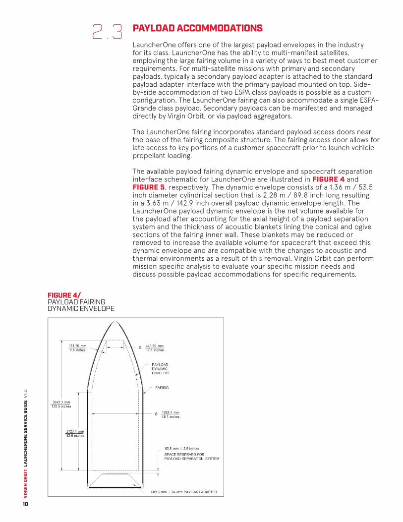
FIGURE 4/ PAYLOAD FAIRING DYNAMIC ENVELOPE
PAYLOAD ACCOMMODATIONSLauncherOne offers one of the largest payload envelopes in the industry for its class. LauncherOne has the ability to multi-manifest satellites, employing the large fairing volume in a variety of ways to best meet customer requirements. For multi-satellite missions with primary and secondary payloads, typically a secondary payload adapter is attached to the standard payload adapter interface with the primary payload mounted on top. Side-by-side accommodation of two ESPA class payloads is possible as a custom configuration. The LauncherOne fairing can also accommodate a single ESPA-Grande class payload. Secondary payloads can be manifested and managed directly by Virgin Orbit, or via payload aggregators.
The LauncherOne fairing incorporates standard payload access doors near the base of the fairing composite structure. The fairing access door allows for late access to key portions of a customer spacecraft prior to launch vehicle propellant loading.
The available payload fairing dynamic envelope and spacecraft separation interface schematic for LauncherOne are illustrated in FIGURE 4 and FIGURE 5, respectively. The dynamic envelope consists of a 1.36 m / 53.5 inch diameter cylindrical section that is 2.28 m / 89.8 inch long resulting in a 3.63 m / 142.9 inch overall payload dynamic envelope length. The LauncherOne payload dynamic envelope is the net volume available for the payload after accounting for the axial height of a payload separation system and the thickness of acoustic blankets lining the conical and ogive sections of the fairing inner wall. These blankets may be reduced or removed to increase the available volume for spacecraft that exceed this dynamic envelope and are compatible with the changes to acoustic and thermal environments as a result of this removal. Virgin Orbit can perform mission specific analysis to evaluate your specific mission needs and discuss possible payload accommodations for specific requirements.
2.3
VIR
GIN
OR
BIT
LA
UN
CH
ERO
NE
SER
VIC
E G
UID
E V
1.0
11
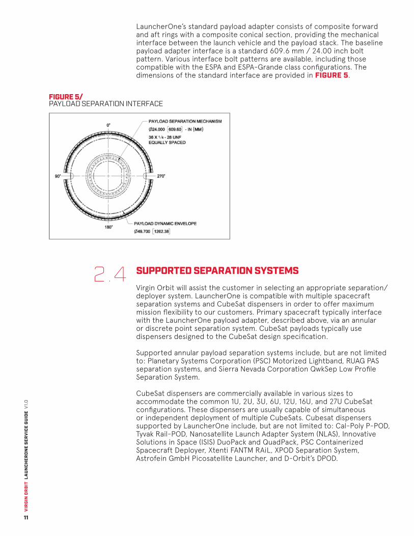
FIGURE 5/ PAYLOAD SEPARATION INTERFACE
SUPPORTED SEPARATION SYSTEMSVirgin Orbit will assist the customer in selecting an appropriate separation/deployer system. LauncherOne is compatible with multiple spacecraft separation systems and CubeSat dispensers in order to offer maximum mission flexibility to our customers. Primary spacecraft typically interface with the LauncherOne payload adapter, described above, via an annular or discrete point separation system. CubeSat payloads typically use dispensers designed to the CubeSat design specification.
Supported annular payload separation systems include, but are not limited to: Planetary Systems Corporation (PSC) Motorized Lightband, RUAG PAS separation systems, and Sierra Nevada Corporation QwkSep Low Profile Separation System.
CubeSat dispensers are commercially available in various sizes to accommodate the common 1U, 2U, 3U, 6U, 12U, 16U, and 27U CubeSat configurations. These dispensers are usually capable of simultaneous or independent deployment of multiple CubeSats. Cubesat dispensers supported by LauncherOne include, but are not limited to: Cal-Poly P-POD, Tyvak Rail-POD, Nanosatellite Launch Adapter System (NLAS), Innovative Solutions in Space (ISIS) DuoPack and QuadPack, PSC Containerized Spacecraft Deployer, Xtenti FANTM RAiL, XPOD Separation System, Astrofein GmbH Picosatellite Launcher, and D-Orbit’s DPOD.
2.4
LauncherOne’s standard payload adapter consists of composite forward and aft rings with a composite conical section, providing the mechanical interface between the launch vehicle and the payload stack. The baseline payload adapter interface is a standard 609.6 mm / 24.00 inch bolt pattern. Various interface bolt patterns are available, including those compatible with the ESPA and ESPA-Grande class configurations. The dimensions of the standard interface are provided in FIGURE 5.

VIR
GIN
OR
BIT
LA
UN
CH
ERO
NE
SER
VIC
E G
UID
E V
1.0
12
Virgin Orbit will conduct analysis of tip off and other payload separation dynamics as necessary to ensure safe separation from the launch vehicle and one that meets your mission requirements. For multi-payload missions, LauncherOne ensures that the deployment sequence allows for adequate separation between all deployed payloads. Following the separation event, the second stage of LauncherOne will perform a Collision/Contamination Avoidance Maneuver (C/CAM), if necessary, in order to minimize contamination and limit the potential for re-contact with the deployed payload.
VIR
GIN
OR
BIT
LA
UN
CH
ERO
NE
SER
VIC
E G
UID
E V
1.0
13
3 TheVirgin Orbit
Launch Service
Process
VIR
GIN
OR
BIT
LA
UN
CH
ERO
NE
SER
VIC
E G
UID
E V
1.0
14
THE VIRGIN LAUNCH SERVICE PROCESSVirgin Orbit’s launch service includes mission planning, accommodation for spacecraft processing, payload-to-launch vehicle integration, and delivery of the spacecraft to orbit. Mission integration activities ensure that customer requirements are met or exceeded and the mission is conducted in a safe, expeditious, and reliable manner. Typical schedule, documentation, and safety considerations are described in the following sections.
LAUNCH SERVICE ELEMENTSAll launches are given the high level of service and attention to detail that comes standard with what you would expect from a Virgin company. To better serve our customers, we offer optional services to further enhance your launch experience and/or accommodate your unique needs.
Standard Services:
• Virgin Orbit Mission Manager: Your concierge for a smooth spacecraft integration and launch.
• Virgin Orbit Interface Control Document: Ensures all of your mission requirements are documented and the launch service complies with your spacecraft needs.
• Trajectory and Performance Analysis: Ensures your payload is delivered to your mission orbit.
• Coupled Loads Analysis: Ensures that your spacecraft is compatible with the launch environment.
• Separation Analysis: Ensures accurate and low risk payload deployment.
• Post-Launch Status Quick-Look: Spacecraft state vector will be made available within 90 minutes after separation based on the L1 navigation solution at separation. A Quick-Look assessment of post-launch status from launch vehicle telemetry data, as well as a preliminary evaluation of mission success, will occur no later than 180 minutes after separation.
• Post-Launch Evaluation Report: A full report will be delivered within 60 days after launch, containing details of launch trajectory, events, and environments.
• Export Compliance: In the case of a non-U.S. Customer and/or Spacecraft Manufacturer, Virgin Orbit will obtain and manage a Technical Assistance Agreement (TAA) from the U.S. State Department.
Optional Services:
• Payload Separation System: Focus on your payload and let us handle the acquisition, delivery, and processing of your separation system to ensure that you are ready for integration.
• Thermal Analysis: Ensure thermal compatibility with sensitive areas of your payload and the launch environment.
• Chase Plane: Watch your launch live from the air!
3
3.1
VIR
GIN
OR
BIT
LA
UN
CH
ERO
NE
SER
VIC
E G
UID
E V
1.0
15
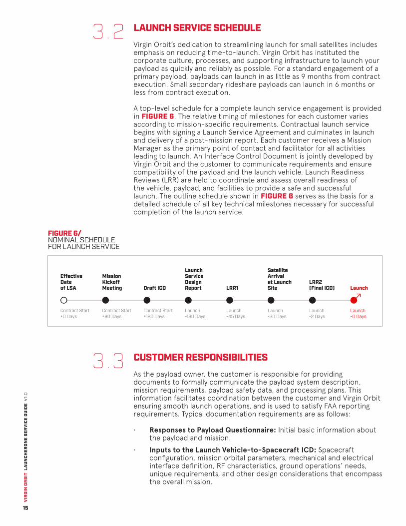
LAUNCH SERVICE SCHEDULEVirgin Orbit’s dedication to streamlining launch for small satellites includes emphasis on reducing time-to-launch. Virgin Orbit has instituted the corporate culture, processes, and supporting infrastructure to launch your payload as quickly and reliably as possible. For a standard engagement of a primary payload, payloads can launch in as little as 9 months from contract execution. Small secondary rideshare payloads can launch in 6 months or less from contract execution.
A top-level schedule for a complete launch service engagement is provided in FIGURE 6. The relative timing of milestones for each customer varies according to mission-specific requirements. Contractual launch service begins with signing a Launch Service Agreement and culminates in launch and delivery of a post-mission report. Each customer receives a Mission Manager as the primary point of contact and facilitator for all activities leading to launch. An Interface Control Document is jointly developed by Virgin Orbit and the customer to communicate requirements and ensure compatibility of the payload and the launch vehicle. Launch Readiness Reviews (LRR) are held to coordinate and assess overall readiness of the vehicle, payload, and facilities to provide a safe and successful launch. The outline schedule shown in FIGURE 6 serves as the basis for a detailed schedule of all key technical milestones necessary for successful completion of the launch service.
3.2
FIGURE 6/ NOMINAL SCHEDULE FOR LAUNCH SERVICE
Effective Date of LSA Draft ICD
LRR2 (Final ICD)
Mission Kickoff Meeting
Launch Service Design Report LaunchLRR1
Satellite Arrival at Launch Site
Contract Start +0 Days
Contract Start +90 Days
Contract Start +180 Days
Launch-180 Days
Launch-45 Days
Launch-30 Days
Launch-2 Days
Launch-0 Days
CUSTOMER RESPONSIBILITIESAs the payload owner, the customer is responsible for providing documents to formally communicate the payload system description, mission requirements, payload safety data, and processing plans. This information facilitates coordination between the customer and Virgin Orbit ensuring smooth launch operations, and is used to satisfy FAA reporting requirements. Typical documentation requirements are as follows:
• Responses to Payload Questionnaire: Initial basic information about the payload and mission.
• Inputs to the Launch Vehicle-to-Spacecraft ICD: Spacecraft configuration, mission orbital parameters, mechanical and electrical interface definition, RF characteristics, ground operations’ needs, unique requirements, and other design considerations that encompass the overall mission.
3.3
VIR
GIN
OR
BIT
LA
UN
CH
ERO
NE
SER
VIC
E G
UID
E V
1.0
16
• Spacecraft mass properties and CAD model: Mass, CG, and moments & products of inertia data, for Virgin Orbit to evaluate launch vehicle integration and flight dynamics.
• ICD Verification Documentation: Verification evidence indicating how each customer ICD requirement was verified (e.g. inspection, analysis, test, demonstration).
• Finite Element Model: Model to enable payload-to-launch vehicle Coupled Loads Analysis.
• Payload Processing Plan: Plan for payload processing and intended use of Virgin Orbit Payload Processing Facilities.
• Safety Documentation: Identification of hazardous materials and quantity of each; and identification of hazardous operations during payload processing.
The customer is separately responsible for obtaining licenses from the appropriate regulatory commission for communication and/or imagery from space (e.g. Federal Communications Commission, International Telecommunications Union, National Oceanic and Atmospheric Administration).
SAFETY AND MISSION ASSURANCEMeasures are in place to ensure safety of personnel and property throughout all aspects of payload processing, vehicle integration, and launch operations. Virgin Orbit strives to exceed the requirements of the Federal Aviation Administration (FAA), the Occupational Safety and Health Administration (OSHA), and other applicable regulatory agencies. Both a Safety Policy and formal Safety and Mission Assurance Process are in place to ensure risks and resulting hazards are methodically identified, and either eliminated or appropriately mitigated. Customer payloads and payload operations are responsible for compliance with these requirements. Virgin Orbit can provide guidance regarding specific safety requirements. The entry point for communication of payload safety data is the payload questionnaire and it contains all questions needed for an FAA Launch License submittal. Virgin Orbit will review the payload documentation for compliance with applicable safety standards, and safety status is assessed during all readiness review meetings.
3.4

VIR
GIN
OR
BIT
LA
UN
CH
ERO
NE
SER
VIC
E G
UID
E V
1.0
17
4Payload Processing and LaunchOperations
VIR
GIN
OR
BIT
LA
UN
CH
ERO
NE
SER
VIC
E G
UID
E V
1.0
18
PAYLOAD PROCESSING AND LAUNCH OPERATIONSPayload integration and launch operations procedures are designed to minimize complexity, ensure system safety, and increase mission reliability. A typical processing flow is described in this section. Virgin Orbit is able to tailor standard payload processing and launch procedures to the customer’s specific mission requirements.
PAYLOAD PROCESSING FACILITIESVirgin Orbit offers a secure, climate-controlled Payload Processing Facility (PPF) at its headquarters in Long Beach, California, for checkout and preparation of customer payloads prior to encapsulation and integration with the launch vehicle. The PPF consists of office spaces and electrical ground support equipment control rooms adjacent to a clean room where payload processing takes place. Common mechanical ground support equipment is available for customer use and customer unique support equipment can be accommodated as well. Baseline services and equipment available at the PPF include:
• Office space, office support functions (print, copy, and fax), and with wired and/or wireless internet access
• Climate-controlled storage space
• Class 100,000 clean room (ISO 8) for customer spacecraft processing and fairing encapsulation
• Power provided for customer electrical ground support equipment at 100V AC, 60 Hz and 230V AC, 50 Hz
• Forklift, scissor lifts, rolling ladders, and small handheld tools
• Consumables including compressed air, helium, and nitrogen
• Virgin Orbit integration support personnel available up to six (6) days a week for ten (10) hours a day, and optional 24/7 support Security measures including electronic access IDs, 24-hour facility security guard, and CCTV.
• Accommodation of payload propellant fueling including cold gas, xenon/krypton, and various “green” propellants. Fully-fueled payload delivery will promote the most efficient integration process, but Virgin Orbit is able to address customer fueling requirements upon request. Fueling of hazardous propellants will occur at an external, Virgin Orbit-procured processing facility.
4
4.1
VIR
GIN
OR
BIT
LA
UN
CH
ERO
NE
SER
VIC
E G
UID
E V
1.0
19
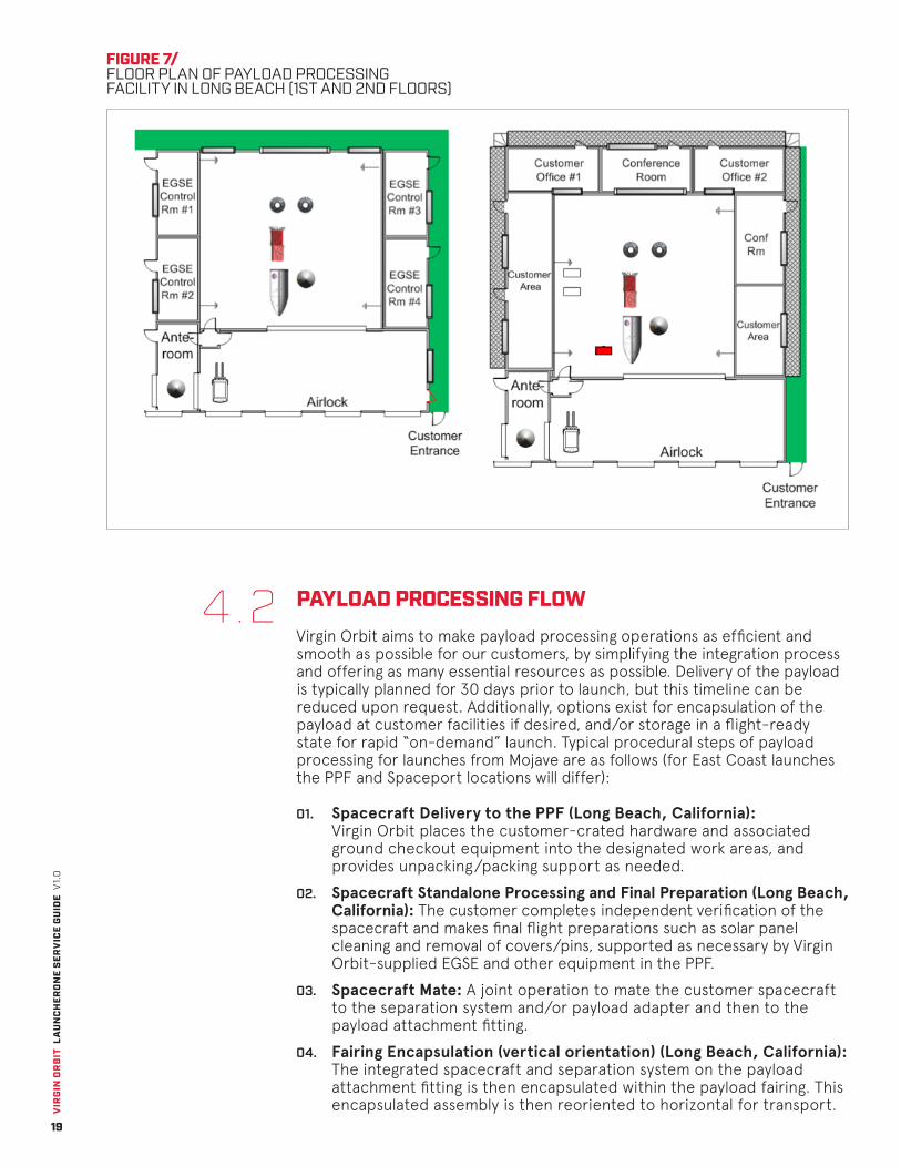
PAYLOAD PROCESSING FLOWVirgin Orbit aims to make payload processing operations as efficient and smooth as possible for our customers, by simplifying the integration process and offering as many essential resources as possible. Delivery of the payload is typically planned for 30 days prior to launch, but this timeline can be reduced upon request. Additionally, options exist for encapsulation of the payload at customer facilities if desired, and/or storage in a flight-ready state for rapid “on-demand” launch. Typical procedural steps of payload processing for launches from Mojave are as follows (for East Coast launches the PPF and Spaceport locations will differ):
01. Spacecraft Delivery to the PPF (Long Beach, California): Virgin Orbit places the customer-crated hardware and associated ground checkout equipment into the designated work areas, and provides unpacking/packing support as needed.
02. Spacecraft Standalone Processing and Final Preparation (Long Beach, California): The customer completes independent verification of the spacecraft and makes final flight preparations such as solar panel cleaning and removal of covers/pins, supported as necessary by Virgin Orbit-supplied EGSE and other equipment in the PPF.
03. Spacecraft Mate: A joint operation to mate the customer spacecraft to the separation system and/or payload adapter and then to the payload attachment fitting.
04. Fairing Encapsulation (vertical orientation) (Long Beach, California): The integrated spacecraft and separation system on the payload attachment fitting is then encapsulated within the payload fairing. This encapsulated assembly is then reoriented to horizontal for transport.
4.2
FIGURE 7/ FLOOR PLAN OF PAYLOAD PROCESSING FACILITY IN LONG BEACH (1ST AND 2ND FLOORS)

VIR
GIN
OR
BIT
LA
UN
CH
ERO
NE
SER
VIC
E G
UID
E V
1.0
20
LAUNCH LOCATIONSLauncherOne operates independently, and because we are not reliant on a government maintained launch range, we are unaffected by many of the external factors that can delay ground based launches from federal ranges such as weather, offline radar tracking assets, vehicles in the launch pad keep-out zone, and manifest jams on the increasingly crowded Eastern and Western ranges. The primary spaceport for LauncherOne is the Mojave Air and Space Port (MHV) in California. Virgin Orbit has completed launch assessments for MHV and is assessing requirements for a variety of lower latitude operating locations, including the Shuttle Landing Facility (SLF) at the Kennedy Space Center (KSC) in Florida, Kona International Airport (KOA) in Hawaii, and former Roosevelt Roads Naval Station in Puerto Rico. Virgin Orbit can also assess alternative launch locations and will pursue approvals to operate from these locations as necessary to support our customers’ needs.
The baseline flight profile involves release of the LauncherOne launch vehicle over the Pacific Ocean, tens of kilometers from the California coastline, after a flight of approximately 30 minutes from Mojave. For low inclination launches, the drop point is optimally located based on the inclination desired for the mission. Due to the large range of the carrier aircraft and the flexible locations for spaceports, the drop point can be as low as 0 degrees latitude for 0 degree inclined orbits. In this case, the drop point could be over 1000 km from the launch port.
4.3
05. Transport to the Spaceport: The encapsulated payload is maintained in a climate controlled, positive pressure environment during transport to the launch port by a Virgin Orbit-supplied transportation system.
06. Integration with the Launch Vehicle (Mojave, California): Virgin Orbit horizontally mates the encapsulated payload assembly to the launch vehicle at the Mojave Spaceport.
07. Late Payload Access (Mojave, California): If required, late access to the payload is available with advance planning.
LAUNCH OPERATIONS FLOWFor standard launch operations, launch occurs within three days of payload encapsulation and transport to the spaceport. Key events in the launch schedule and typical timing relative to takeoff are as follows:
01. LauncherOne vehicle integration and checkout (L-3 days and earlier)
02. Payload mate to LauncherOne (L-3 days)
03. Launch Readiness Review (L-2 days)
04. Rollout and mate of LauncherOne with payload to carrier aircraft (L-1 day)
05. Propellant loading (T-6 hours to T-60 minutes)
06. 747 aircraft engine start and L1 GSE disconnect (T-30 minutes)
07. 747 aircraft take-off; LauncherOne purge provided to payload encapsulated environment by the carrier aircraft (T-30 minutes)
08. LauncherOne release and launch (T+0 minutes)
09. Second stage ignition (T+ 3 minutes)
10. Payload injection (Mission dependent, but approximately T+60 min)
4.4

VIR
GIN
OR
BIT
LA
UN
CH
ERO
NE
SER
VIC
E G
UID
E V
1.0
21
5PayloadEnvironments
VIR
GIN
OR
BIT
LA
UN
CH
ERO
NE
SER
VIC
E G
UID
E V
1.0
22
+X
+X +X
+Z
+Z
+Y
+Y
PAYLOAD ENVIRONMENTSLauncherOne’s payload environments are competitive with other similar launch vehicles throughout the flight profile, including ground segments, captive carry, and launch vehicle ascent. The predicted environmental conditions experienced by a typical payload are detailed in the following subsections. This payload environment data is provided for initial planning purposes only. Mission-specific analysis of expected payload environments is performed by Virgin Orbit as a standard service, and documented in the ICD.
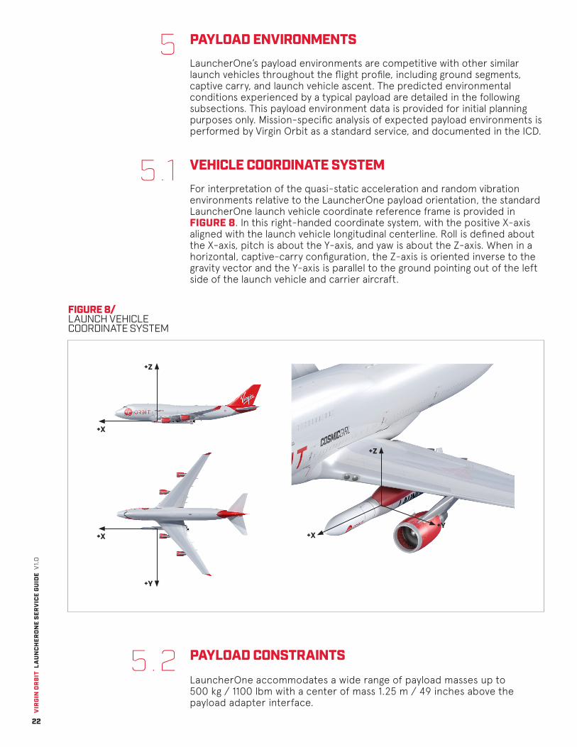
VEHICLE COORDINATE SYSTEMFor interpretation of the quasi-static acceleration and random vibration environments relative to the LauncherOne payload orientation, the standard LauncherOne launch vehicle coordinate reference frame is provided in FIGURE 8. In this right-handed coordinate system, with the positive X-axis aligned with the launch vehicle longitudinal centerline. Roll is defined about the X-axis, pitch is about the Y-axis, and yaw is about the Z-axis. When in a horizontal, captive-carry configuration, the Z-axis is oriented inverse to the gravity vector and the Y-axis is parallel to the ground pointing out of the left side of the launch vehicle and carrier aircraft.
5
5.1
FIGURE 8/ LAUNCH VEHICLE COORDINATE SYSTEM
5.2 PAYLOAD CONSTRAINTS
LauncherOne accommodates a wide range of payload masses up to 500 kg / 1100 lbm with a center of mass 1.25 m / 49 inches above the payload adapter interface.
VIR
GIN
OR
BIT
LA
UN
CH
ERO
NE
SER
VIC
E G
UID
E V
1.0
23
5.4
TABLE 4/ LAUNCHERONE PRIMARY PAYLOAD DESIGN LOAD FACTORS
TABLE 5/ LAUNCHERONE DESIGN LOAD FACTORS AT THE STANDARD INTERFACE
Type
Acceleration (g)
Axial (x)
-4g / +8g
Lateral (y)
+/- 5g
Lateral (z)
+/- 8g
Frequency (Hz)
100
1,000
10,000
Shock Maximum Predicted Environment, All Axes (Shock Response Spectrum g-peak, Q=10)
50
3,000
3,000
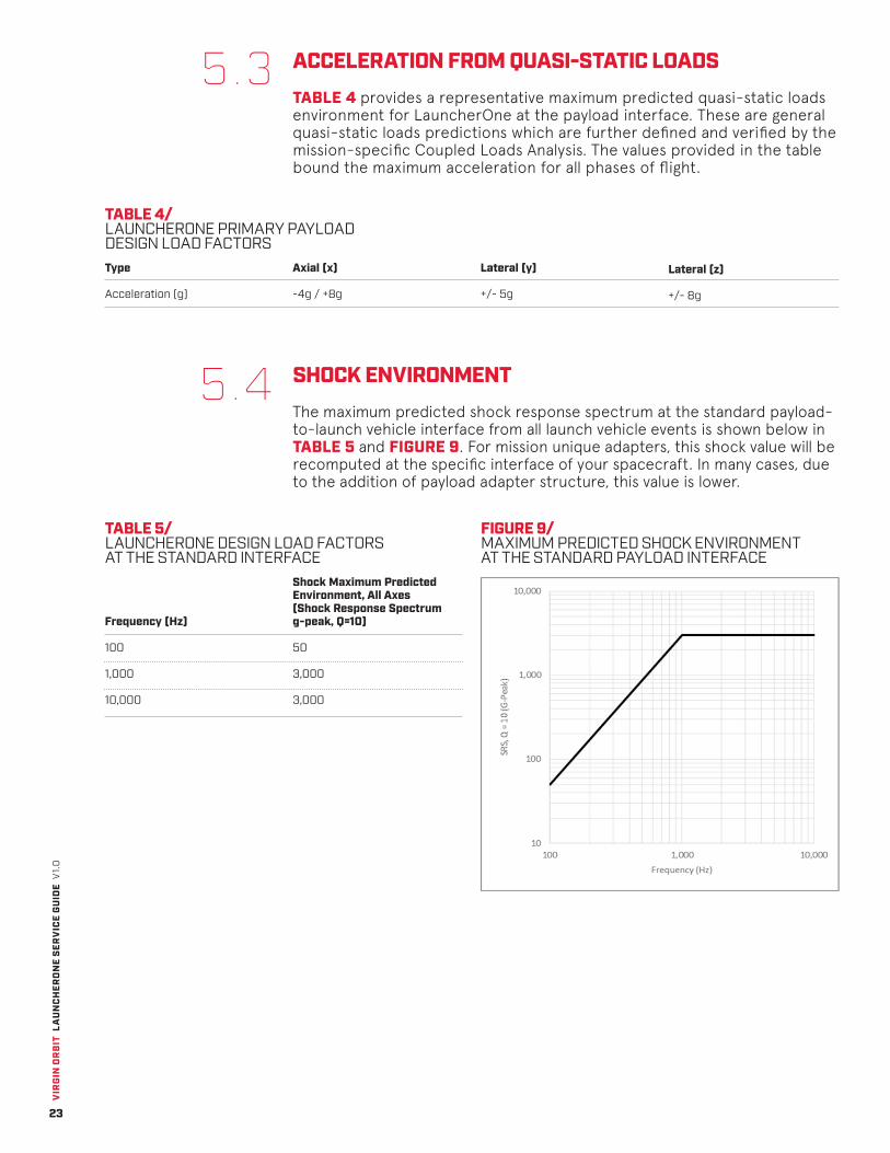
SHOCK ENVIRONMENTThe maximum predicted shock response spectrum at the standard payload-to-launch vehicle interface from all launch vehicle events is shown below in TABLE 5 and FIGURE 9. For mission unique adapters, this shock value will be recomputed at the specific interface of your spacecraft. In many cases, due to the addition of payload adapter structure, this value is lower.
5.3 ACCELERATION FROM QUASI-STATIC LOADSTABLE 4 provides a representative maximum predicted quasi-static loads environment for LauncherOne at the payload interface. These are general quasi-static loads predictions which are further defined and verified by the mission-specific Coupled Loads Analysis. The values provided in the table bound the maximum acceleration for all phases of flight.
FIGURE 9/ MAXIMUM PREDICTED SHOCK ENVIRONMENT AT THE STANDARD PAYLOAD INTERFACE

VIR
GIN
OR
BIT
LA
UN
CH
ERO
NE
SER
VIC
E G
UID
E V
1.0
24
RANDOM VIBRATIONThe LauncherOne primary payload predicted maximum random vibration environment in the axial and lateral direction are shown below. For mission unique adapters, this shock value will be recomputed at the particular interface of your spacecraft.
5.5
TABLE 6/ LAUNCHERONE MAXIMUM PREDICTED RANDOM VIBRATION ENVIRONMENT (AXIAL) AT THE STANDARD PAYLOAD Frequency (Hz)
20
50
80
2,000
9.86 g root mean squared (grms)
Power Spectral Density (PSD) (g^2/Hz)
0.007
0.016
0.050
0.050
FIGURE 10/ MAXIMUM PREDICTED RANDOM VIBRATION ENVIRONMENT (AXIAL) AT THE STANDARD PAYLOAD INTERFACE
TABLE 7/ LAUNCHERONE MAXIMUM PREDICTED RANDOM VIBRATION ENVIRONMENT (LATERAL) AT THE STANDARD PAYLOAD INTERFACE
FIGURE 11/ MAXIMUM PREDICTED RANDOM VIBRATION ENVIRONMENT (LATERAL) AT THE STANDARD PAYLOAD INTERFACE
Frequency (Hz)
0
50
85
100
400
525
2000
9.34 grms
Power Spectral Density (PSD) (g^2/Hz)
0.010
0.020
0.020
0.025
0.025
0.050
0.050

VIR
GIN
OR
BIT
LA
UN
CH
ERO
NE
SER
VIC
E G
UID
E V
1.0
25
FIGURE 12/ MAXIMUM PREDICTED ACOUSTIC ENVIRONMENT
5.6 ACOUSTICSThe maximum predicted acoustic environment for a typical payload fill factor is defined in TABLE 8 and FIGURE 12. For missions of very large or small fill factors, a mission unique acoustic analysis is performed.
TABLE 8/ MAXIMUM PREDICTED ACOUSTIC ENVIRONMENT
Frequency (Hz)
20
25
31.5
40
50
63
80
100
125
160
200
250
315
400
Sound Pressure Level (SPL)(dB, Reference: 2e-5 Pa)
119.0
120.0
121.0
122.0
123.0
124.0
125.0
125.7
126.5
126.8
127.7
129.2
130.5
131.7
Frequency (Hz)
500
630
800
1,000
1,250
1,600
2,000
2,500
3,150
4,000
5,000
6,300
8,000
10,000
SPL(dB, Reference: 2e-5 Pa)
132.7
133.5
134.2
134.7
135.0
135.0
134.0
132.8
131.3
129.2
126.9
123.8
119.8
115.2
Overall Sound Pressure Level (OASPL) = 144.77 dB
VIR
GIN
OR
BIT
LA
UN
CH
ERO
NE
SER
VIC
E G
UID
E V
1.0
26
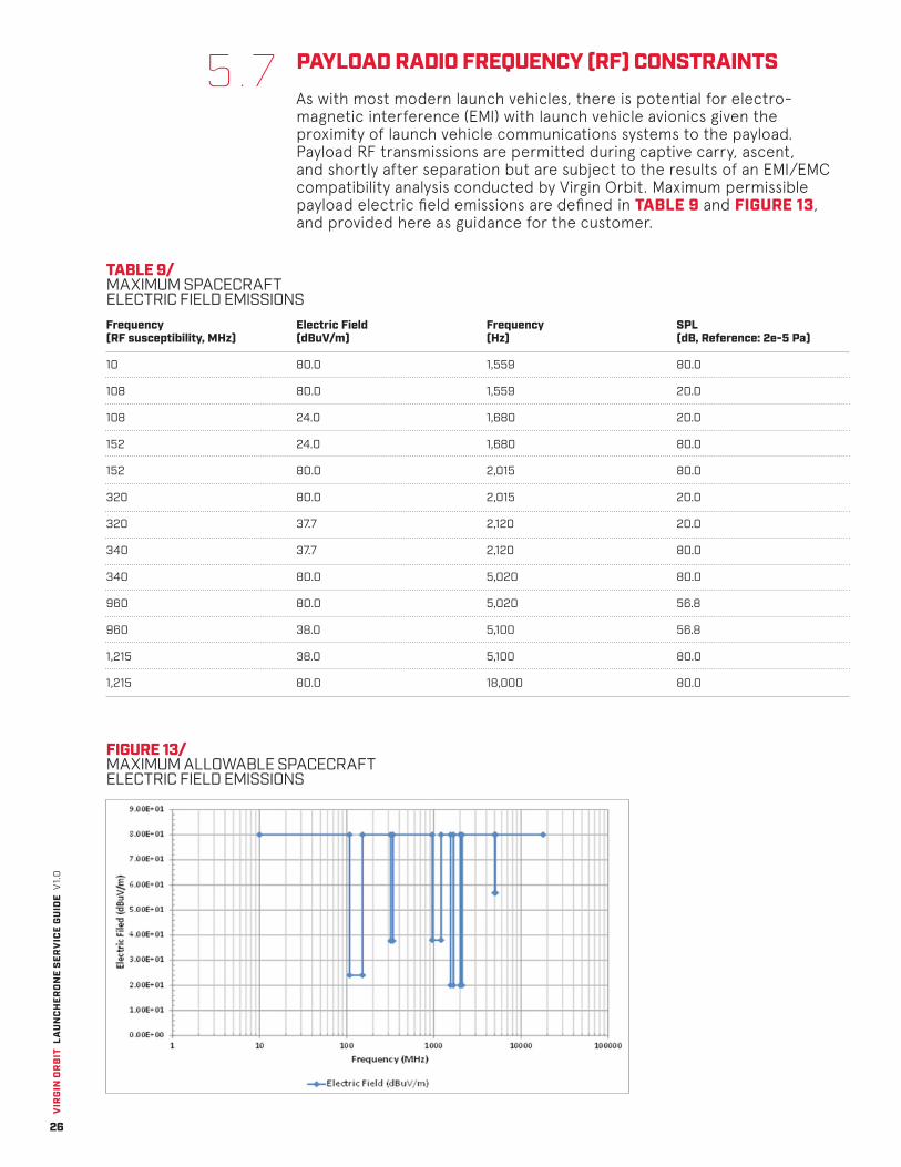
5.7 PAYLOAD RADIO FREQUENCY (RF) CONSTRAINTSAs with most modern launch vehicles, there is potential for electro-magnetic interference (EMI) with launch vehicle avionics given the proximity of launch vehicle communications systems to the payload. Payload RF transmissions are permitted during captive carry, ascent, and shortly after separation but are subject to the results of an EMI/EMC compatibility analysis conducted by Virgin Orbit. Maximum permissible payload electric field emissions are defined in TABLE 9 and FIGURE 13, and provided here as guidance for the customer.
TABLE 9/ MAXIMUM SPACECRAFT ELECTRIC FIELD EMISSIONS
FIGURE 13/ MAXIMUM ALLOWABLE SPACECRAFT ELECTRIC FIELD EMISSIONS
Frequency(RF susceptibility, MHz)
10
108
108
152
152
320
320
340
340
960
960
1,215
1,215
Electric Field (dBuV/m)
80.0
80.0
24.0
24.0
80.0
80.0
37.7
37.7
80.0
80.0
38.0
38.0
80.0
Frequency(Hz)
1,559
1,559
1,680
1,680
2,015
2,015
2,120
2,120
5,020
5,020
5,100
5,100
18,000
SPL(dB, Reference: 2e-5 Pa)
80.0
20.0
20.0
80.0
80.0
20.0
20.0
80.0
80.0
56.8
56.8
80.0
80.0
VIR
GIN
OR
BIT
LA
UN
CH
ERO
NE
SER
VIC
E G
UID
E V
1.0
27
5.8
5.9
5.10
THERMAL AND HUMIDITY ENVIRONMENTConditioned air is provided to the payload during all phases of operations until receipt of the payload container to separation from the carrier aircraft. The payload thermal environment is maintained at 21 ± 3.5 degrees Celsius (69.8 ± 6.3 degrees Fahrenheit), and relative humidity is controlled from 40-60%. There will be short outages (up to 30 minutes) for connections to different configurations for the various phases of ground operations. These outages will not result in a violation of the previously described thermal environment.
During captive carry flight, the fairing is purged with temperature and contamination controlled air to maintain adequate temperature and cleanliness in the fairing volume. The bulk air temperature in the payload fairing is controlled from 15.5 +/- 11.1 degrees Celsius (60 +/- 20 degrees Fahrenheit). At the customer’s request, electrical power is provided to the payload during captive carry for internal spacecraft thermal control.
FAIRING PRESSURE ENVIRONMENTDuring ascent, the maximum depressurization rate for LauncherOne is less than 2758 Pa/second (0.4 psi/second) from liftoff through immediately prior to fairing separation, except for a brief period during the transonic spike, in which a time-averaged decay rate that is no higher than 0.55 psi/sec for no more than 5 seconds.
SEPARATION SYSTEM SIGNALFor the standard launch vehicle-to-payload electrical interface scheme, the LauncherOne payload controller provides a primary and redundant separation signal directly to the payload separation system. The payload controller is capable of providing multiple signals enabling multi-spacecraft missions.
SPACECRAFT ELECTRICAL INTERFACEAt the customer’s request, the payload adapter wire harness can include a spacecraft umbilical connector to provide a connection from the spacecraft to customer electrical ground support equipment (EGSE). This extra harness can be used to supply power and provide a data connection to the payload during storage and vehicle-level integration. These payload accommodations are defined in TABLE 10 and TABLE 11.
5.11

VIR
GIN
OR
BIT
LA
UN
CH
ERO
NE
SER
VIC
E G
UID
E V
1.0
28
FIGURE 14/ PAYLOAD ELECTRICAL INTERFACE DIAGRAM
TABLE 10/ PAYLOAD POWER SERVICES
TABLE 11/ PAYLOAD COMMUNICATIONS SERVICES
Description
Voltage
Description
Unprocessed Twisted Pairs
EGSE Telemetry, Captive Carry
EGSE Telemetry, Ground Operations
Provision
28V power (regulated to within 18-36 V) can be provided to the payload at the customer’s request.
28V power is capable of 1A current during captive carry flight. During ground operations, 3 Amps is available to the payload.
Provision
Payload communication over 8 twisted pair to GSE can be supported to provide Command and Telemetry during ground processing at the customer’s request.
100 Kbps payload telemetry, stored to aircraft Data Acquisition Storage, is supported during captive carry.
1 Mbps payload telemetry is supported during ground operations.

VIR
GIN
OR
BIT
LA
UN
CH
ERO
NE
SER
VIC
E G
UID
E V
1.0
29
6AboutVirgin Orbit
VIR
GIN
OR
BIT
LA
UN
CH
ERO
NE
SER
VIC
E G
UID
E V
1.0
30
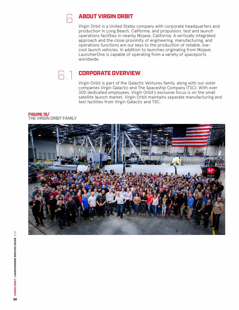
ABOUT VIRGIN ORBITVirgin Orbit is a United States company with corporate headquarters and production in Long Beach, California, and propulsion, test and launch operations facilities in nearby Mojave, California. A vertically integrated approach and the close proximity of engineering, manufacturing, and operations functions are our keys to the production of reliable, low-cost launch vehicles. In addition to launches originating from Mojave, LauncherOne is capable of operating from a variety of spaceports worldwide.
CORPORATE OVERVIEWVirgin Orbit is part of the Galactic Ventures family, along with our sister companies Virgin Galactic and The Spaceship Company (TSC). With over 300 dedicated employees, Virgin Orbit’s exclusive focus is on the small satellite launch market. Virgin Orbit maintains separate manufacturing and test facilities from Virgin Galactic and TSC.
6
6.1
FIGURE 15/ THE VIRGIN ORBIT FAMILY
VIR
GIN
OR
BIT
LA
UN
CH
ERO
NE
SER
VIC
E G
UID
E V
1.0
31
6.2
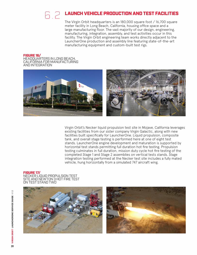
FIGURE 16/ HEADQUARTERS IN LONG BEACH, CALIFORNIA FOR MANUFACTURING AND INTEGRATION
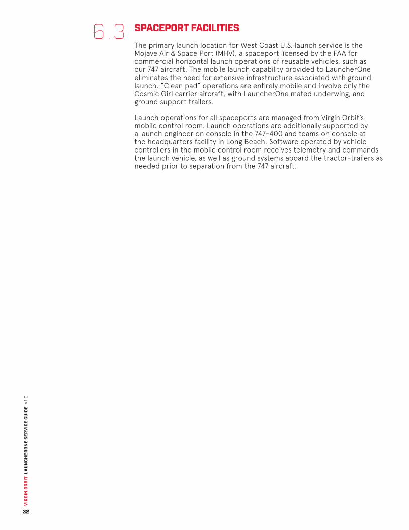
FIGURE 17/ NECKER LIQUID PROPULSION TEST SITE AND NEWTON 3 HOT FIRE TEST ON TEST STAND TWO
LAUNCH VEHICLE PRODUCTION AND TEST FACILITIES
The Virgin Orbit headquarters is an 180,000 square foot / 16,700 square meter facility in Long Beach, California, housing office space and a large manufacturing floor. The vast majority of our design, engineering, manufacturing, integration, assembly, and test activities occur in this facility. The Virgin Orbit engineering team works directly adjacent to the LauncherOne production and assembly line featuring state-of-the-art manufacturing equipment and custom-built test rigs.
Virgin Orbit’s Necker liquid propulsion test site in Mojave, California leverages existing facilities from our sister company Virgin Galactic, along with new facilities built specifically for LauncherOne. Liquid propulsion, composite tank, and overall stage testing is performed here at one of eight test stands. LauncherOne engine development and maturation is supported by horizontal test stands permitting full duration hot fire testing. Propulsion testing culminates in full duration, mission duty cycle hot fire testing of the completed Stage 1 and Stage 2 assemblies on vertical tests stands. Stage integration testing performed at the Necker test site includes a fully mated vehicle, hung horizontally from a simulated 747 aircraft wing.
VIR
GIN
OR
BIT
LA
UN
CH
ERO
NE
SER
VIC
E G
UID
E V
1.0
32
6.3 SPACEPORT FACILITIES
The primary launch location for West Coast U.S. launch service is the Mojave Air & Space Port (MHV), a spaceport licensed by the FAA for commercial horizontal launch operations of reusable vehicles, such as our 747 aircraft. The mobile launch capability provided to LauncherOne eliminates the need for extensive infrastructure associated with ground launch. “Clean pad” operations are entirely mobile and involve only the Cosmic Girl carrier aircraft, with LauncherOne mated underwing, and ground support trailers.
Launch operations for all spaceports are managed from Virgin Orbit’s mobile control room. Launch operations are additionally supported by a launch engineer on console in the 747-400 and teams on console at the headquarters facility in Long Beach. Software operated by vehicle controllers in the mobile control room receives telemetry and commands the launch vehicle, as well as ground systems aboard the tractor-trailers as needed prior to separation from the 747 aircraft.

VIR
GIN
OR
BIT
LA
UN
CH
ERO
NE
SER
VIC
E G
UID
E V
1.0
33
DocumentReference
7

VIR
GIN
OR
BIT
LA
UN
CH
ERO
NE
SER
VIC
E G
UID
E V
1.0
34
LIST OF ACRONYMS
AFSS CAD CCAFS C/CAM CLA EGSE ESPA EMC EMI FAA GSE ICD KOA KSC LEO LOX LSA MHV N3 N4 OSHA PPF PSC PRR PSD RAAN RF RP SLF SSO
7.1
7.2
Autonomous Flight Safety SystemComputer-Aided DesignCape Canaveral Air Force StationCollision/Contamination Avoidance ManeuverCoupled Loads AnalysisElectrical Ground Support EquipmentEELV Secondary Payload AdapterElectromagnetic CompatibilityElectromagnetic InterferenceFederal Aviation AdministrationGround Support EquipmentInterface Control DocumentKona International AirportKennedy Space CenterLow Earth OrbitLiquid OxygenLaunch Services AgreementMojave Air and Space PortNewton 3 [1st stage engine]Newton 4 [2nd stage engine]Occupational Safety and Health AdministrationPayload Processing FacilityPlanetary Systems CorporationPayload Readiness ReviewPower Spectral DensityRight Ascension of Ascending NodeRadio FrequencyRocket PropellantShuttle Landing FacilitySun-Synchronous Orbit
LIST OF TABLES
Table 1. Table 2. Table 3. Table 4. Table 5. Table 6.
Table 7.
Table 8.Table 9. Table 10.Table 11.
Launch Services Quick Reference 6Typical Orbital Injection Accuracy (3 sigma) 9Typical Pre-Separation Attitude and Spin-Rate Accuracies (3 sigma) 9LauncherOne Primary Payload Design Load Factors 23LauncherOne Design Load Factors at the Standard Interface 23LauncherOne Maximum Predicted Random Vibration Environment (Axial) at the Standard Payload Interface 24LauncherOne Maximum Predicted Random Vibration Environment (Lateral) at the Standard Payload Interface 24Maximum Predicted Acoustic Environment 25Maximum Spacecraft Electric Field Emissions 26Payload Power Services 28Payload Communications Services 28
VIR
GIN
OR
BIT
LA
UN
CH
ERO
NE
SER
VIC
E G
UID
E V
1.0
35
7.3 LIST OF FIGURES
Figure 1. Figure 2. Figure 3. Figure 4. Figure 5. Figure 6. Figure 7.
Figure 8.Figure 9.
Figure 10.
Figure 11.
Figure 12.Figure 13.Figure 14.Figure 15.Figure 16.
Figure 17.
LauncherOne System Expanded View 4LauncherOne Sample Payload Configurations 5Orbital Payload Delivery Performance Curves 8Payload Fairing Dynamic Envelope 10Payload Separation Interface 11Nominal Schedule for Launch Service 15Floor Plan of Payload Processing Facility in Long Beach (1st and 2nd floors) 19Launch Vehicle Coordinate System 22Maximum Predicted Shock Environment at the Standard Payload Interface 23Maximum Predicted Random Vibration Environment (Axial) at the Standard Payload Interface 24Maximum Predicted Random Vibration Environment (Lateral) at the Standard Payload Interface 24Maximum Predicted Acoustic Environment 25Maximum Allowable Spacecraft Electric Field Emissions 26Payload Electrical Interface Diagram 28The Virgin Orbit Family 30Headquarters in Long Beach, California for Manufacturing and Integration 31Necker Liquid Propulsion Test Site and Newton 3 Hot Fire Test on Test Stand Two 31

Virgin Orbit, LLC / Version 1.0 / 7 August 2017
For questions about bookings, capabilities, or this User’s Guide itself, please do not hesitate to contact Virgin Orbit at [email protected]. Please note that this customer brochure is a working document, and as such is revised and updated periodically. Virgin Orbit encourage readers to visit virginorbit.com frequently to ensure they have the latest revision.


![WELCOME [static1.squarespace.com]static1.squarespace.com/.../1437491522647/AOG2015_Program.pdf · WELCOME A marketplace, performance space and a gathering place for friends and families,](https://img.pdfslide.us/doc/110x75/5b79a5a97f8b9a703b8e12b1/welcome-welcome-a-marketplace-performance-space-and-a-gathering-place-for.jpg)