Embed Size (px)
Citation preview

RS/6000 7043 43P Series IBM
Service Guide
SA38-0512-03

Fourth Edition (October 1998)
The following paragraph does not apply to the United Kingdom or any country wheresuch provisions are inconsistent with local law: THIS PUBLICATION IS PROVIDED “ASIS” WITHOUT WARRANTY OF ANY KIND, EITHER EXPRESS OR IMPLIED, INCLUDING,BUT NOT LIMITED TO, THE IMPLIED WARRANTIES OF MERCHANTABILITY OR FITNESSFOR A PARTICULAR PURPOSE. Some states do not allow disclaimer of express or impliedwarranties in certain transactions, therefore, this statement may not apply to you.
This publication could include technical inaccuracies or typographical errors. Changes areperiodically made to the information herein; these changes will be incorporated in new editionsof the publication. The manufacturer may make improvements and/or changes in theproduct(s) and/or the program(s) described in this publication at any time, without notice.
It is possible that this publication may contain reference to, or information about, products(machines and programs), programming, or services that are not announced in your country.Such references or information must not be construed to mean that these products,programming, or services will be announced in your country. Any reference to a specificlicensed program in this publication is not intended to state or imply that you can use only thatlicensed program. You can use any functionally equivalent program instead.
Requests for technical information about products should be made to your authorized reselleror marketing representative.
International Business Machines Corporation 1996, 1998. All rights reserved.Note to U.S. Government Users -- Documentation related to restricted rights -- Use,duplication or disclosure is subject to restrictions set forth is GSA ADP Schedule Contract withIBM Corp.

Contents
Communications Statements . . . . . . . . . . . . . . . . . . . . . . . . . . . . . viiFederal Communications Commission (FCC) Statement . . . . . . . . . . . . . . viiEuropean Union (EU) Statement . . . . . . . . . . . . . . . . . . . . . . . . . . . . viiiInternational Electrotechnical Commission (IEC) Statement . . . . . . . . . . . . viiiUnited Kingdom Telecommunications Safety Requirements . . . . . . . . . . . . viiiAvis de conformité aux normes du ministère des Communications du Canada . ixCanadian Department of Communications Compliance Statement . . . . . . . . ixVCCI Statement . . . . . . . . . . . . . . . . . . . . . . . . . . . . . . . . . . . . . ixRadio Protection for Germany . . . . . . . . . . . . . . . . . . . . . . . . . . . . . ix
Safety Notices . . . . . . . . . . . . . . . . . . . . . . . . . . . . . . . . . . . . . . xiLaser Safety Information . . . . . . . . . . . . . . . . . . . . . . . . . . . . . . . . xii
Environmental Notices . . . . . . . . . . . . . . . . . . . . . . . . . . . . . . . . . xiiiProduct Recycling and Disposal . . . . . . . . . . . . . . . . . . . . . . . . . . . . xiiiBattery Return Program . . . . . . . . . . . . . . . . . . . . . . . . . . . . . . . . . xiiiEnvironmental Design . . . . . . . . . . . . . . . . . . . . . . . . . . . . . . . . . . xiii
About This Book . . . . . . . . . . . . . . . . . . . . . . . . . . . . . . . . . . . . xvISO 9000 . . . . . . . . . . . . . . . . . . . . . . . . . . . . . . . . . . . . . . . . . xvRelated Publications . . . . . . . . . . . . . . . . . . . . . . . . . . . . . . . . . . . xvTrademarks . . . . . . . . . . . . . . . . . . . . . . . . . . . . . . . . . . . . . . . . xvi
Chapter 1. Reference Information . . . . . . . . . . . . . . . . . . . . . . . . . 1-1Specifications (for Model 140, Model 150, and Model 240) . . . . . . . . . . . . . 1-4System Board Locations (for Model 140) . . . . . . . . . . . . . . . . . . . . . . . 1-6Model 140 System Board Jumper Settings . . . . . . . . . . . . . . . . . . . . . . 1-8Riser Card (for Model 140) . . . . . . . . . . . . . . . . . . . . . . . . . . . . . . . 1-9System Board Locations (for Model 150) . . . . . . . . . . . . . . . . . . . . . . 1-10System Board Jumper Settings (for Model 150) . . . . . . . . . . . . . . . . . . 1-12Riser Card (for Model 150) . . . . . . . . . . . . . . . . . . . . . . . . . . . . . . 1-13System Board Locations (for Model 240) . . . . . . . . . . . . . . . . . . . . . . 1-14System Board Jumper Settings (for Model 240) . . . . . . . . . . . . . . . . . . 1-16Riser Card (for Model 240) . . . . . . . . . . . . . . . . . . . . . . . . . . . . . . 1-17SCSI Bus Termination . . . . . . . . . . . . . . . . . . . . . . . . . . . . . . . . . 1-18Power Cables . . . . . . . . . . . . . . . . . . . . . . . . . . . . . . . . . . . . . . 1-18Service Inspection Guide . . . . . . . . . . . . . . . . . . . . . . . . . . . . . . . 1-19
Chapter 2. Maintenance Analysis Procedures (MAPs) . . . . . . . . . . . . . 2-1Entry MAP . . . . . . . . . . . . . . . . . . . . . . . . . . . . . . . . . . . . . . . . . 2-1MAP 1020: Problem Determination . . . . . . . . . . . . . . . . . . . . . . . . . . 2-7
Preface iii

MAP 1240: Memory Problem Resolution . . . . . . . . . . . . . . . . . . . . . . 2-12MAP 1520: Power . . . . . . . . . . . . . . . . . . . . . . . . . . . . . . . . . . . 2-15MAP 1540: Minimum Configuration . . . . . . . . . . . . . . . . . . . . . . . . . 2-21MAP 1540A: Minimum Configuration (for the Model 140 and Model 150) . . . 2-22MAP 1540B: Minimum Configuration (for the Model 240) . . . . . . . . . . . . . 2-39
Chapter 3. Error Code to FRU Index for the Model 140 and Model 240 . . . 3-1POST Error Codes . . . . . . . . . . . . . . . . . . . . . . . . . . . . . . . . . . . . 3-2Firmware Error Codes . . . . . . . . . . . . . . . . . . . . . . . . . . . . . . . . . . 3-4Firmware Checkpoints . . . . . . . . . . . . . . . . . . . . . . . . . . . . . . . . . 3-14Firmware Location Codes . . . . . . . . . . . . . . . . . . . . . . . . . . . . . . . 3-21
Chapter 4. Error Code to FRU Index for the Model 150 . . . . . . . . . . . . 4-1Error Codes . . . . . . . . . . . . . . . . . . . . . . . . . . . . . . . . . . . . . . . . 4-1Bus SRN to FRU Reference Table . . . . . . . . . . . . . . . . . . . . . . . . . . 4-11Firmware Checkpoints . . . . . . . . . . . . . . . . . . . . . . . . . . . . . . . . . 4-13Boot Problems/Concerns . . . . . . . . . . . . . . . . . . . . . . . . . . . . . . . 4-27
Chapter 5. Location Codes (Model 150 only) . . . . . . . . . . . . . . . . . . . 5-1Physical Location Codes . . . . . . . . . . . . . . . . . . . . . . . . . . . . . . . . 5-1AIX Location Codes . . . . . . . . . . . . . . . . . . . . . . . . . . . . . . . . . . . 5-4
Chapter 6. Loading the System Diagnostics . . . . . . . . . . . . . . . . . . . 6-1Service Mode Boot: Loading Diagnostics . . . . . . . . . . . . . . . . . . . . . . . 6-2Standalone vs. Online Diagnostics . . . . . . . . . . . . . . . . . . . . . . . . . . . 6-4
Chapter 7. System Management Services . . . . . . . . . . . . . . . . . . . . . 7-1Graphical System Management Services . . . . . . . . . . . . . . . . . . . . . . . 7-1Config . . . . . . . . . . . . . . . . . . . . . . . . . . . . . . . . . . . . . . . . . . . 7-4MultiBoot (Model 150 only) . . . . . . . . . . . . . . . . . . . . . . . . . . . . . . . 7-6Boot (Model 140 and Model 240) . . . . . . . . . . . . . . . . . . . . . . . . . . . 7-9Utilities . . . . . . . . . . . . . . . . . . . . . . . . . . . . . . . . . . . . . . . . . . 7-11Password . . . . . . . . . . . . . . . . . . . . . . . . . . . . . . . . . . . . . . . . 7-13Audio (Model 140 and Model 240 only) . . . . . . . . . . . . . . . . . . . . . . . 7-17Hard Disk Spin Up Delay (Model 150 only) . . . . . . . . . . . . . . . . . . . . . 7-18Error Log . . . . . . . . . . . . . . . . . . . . . . . . . . . . . . . . . . . . . . . . 7-19RIPL . . . . . . . . . . . . . . . . . . . . . . . . . . . . . . . . . . . . . . . . . . . 7-20SCSI ID . . . . . . . . . . . . . . . . . . . . . . . . . . . . . . . . . . . . . . . . . 7-23Firmware Update . . . . . . . . . . . . . . . . . . . . . . . . . . . . . . . . . . . . 7-24Text-Based System Management Services . . . . . . . . . . . . . . . . . . . . . 7-26Display Configuration . . . . . . . . . . . . . . . . . . . . . . . . . . . . . . . . . 7-28MultiBoot Menu (Model 150) . . . . . . . . . . . . . . . . . . . . . . . . . . . . . 7-29Utilities . . . . . . . . . . . . . . . . . . . . . . . . . . . . . . . . . . . . . . . . . . 7-33Select Language . . . . . . . . . . . . . . . . . . . . . . . . . . . . . . . . . . . . 7-43
iv 7043 43P Series Service Guide

Open Firmware Command Line . . . . . . . . . . . . . . . . . . . . . . . . . . . 7-44
Chapter 8. Removal and Replacement Procedures . . . . . . . . . . . . . . . 8-1Handling Static–Sensitive Devices . . . . . . . . . . . . . . . . . . . . . . . . . . . 8-2Cover . . . . . . . . . . . . . . . . . . . . . . . . . . . . . . . . . . . . . . . . . . . . 8-3Power Supply . . . . . . . . . . . . . . . . . . . . . . . . . . . . . . . . . . . . . . . 8-6Front Bezel and Power Switch . . . . . . . . . . . . . . . . . . . . . . . . . . . . 8-10Media Fan . . . . . . . . . . . . . . . . . . . . . . . . . . . . . . . . . . . . . . . . 8-12Internal Media Drives . . . . . . . . . . . . . . . . . . . . . . . . . . . . . . . . . 8-13Adapter . . . . . . . . . . . . . . . . . . . . . . . . . . . . . . . . . . . . . . . . . 8-19Memory Modules . . . . . . . . . . . . . . . . . . . . . . . . . . . . . . . . . . . . 8-20Processor Card (for the Model 240) . . . . . . . . . . . . . . . . . . . . . . . . . 8-24L2 Cache Card (for Model 140 Only) . . . . . . . . . . . . . . . . . . . . . . . . 8-26System Board . . . . . . . . . . . . . . . . . . . . . . . . . . . . . . . . . . . . . . 8-28Riser Card . . . . . . . . . . . . . . . . . . . . . . . . . . . . . . . . . . . . . . . . 8-31I/O Panel . . . . . . . . . . . . . . . . . . . . . . . . . . . . . . . . . . . . . . . . 8-33Fan and Speaker Assembly . . . . . . . . . . . . . . . . . . . . . . . . . . . . . . 8-34Battery . . . . . . . . . . . . . . . . . . . . . . . . . . . . . . . . . . . . . . . . . . 8-36
Chapter 9. Parts Information . . . . . . . . . . . . . . . . . . . . . . . . . . . . . 9-1System Unit . . . . . . . . . . . . . . . . . . . . . . . . . . . . . . . . . . . . . . . . 9-2System Board, Cables, and Accessories . . . . . . . . . . . . . . . . . . . . . . . 9-4Keyboard and Mouse . . . . . . . . . . . . . . . . . . . . . . . . . . . . . . . . . . 9-6Power Cables . . . . . . . . . . . . . . . . . . . . . . . . . . . . . . . . . . . . . . . 9-9
Appendix A. Interpreting Firmware Error Codes . . . . . . . . . . . . . . . . A-1
Index . . . . . . . . . . . . . . . . . . . . . . . . . . . . . . . . . . . . . . . . . . . X-1
Reader's Comments — We'd Like to Hear From You . . . . . . . . . . . . . X-3
Preface v

vi 7043 43P Series Service Guide

Communications Statements
The following statement applies to this product. The statement for other productsintended for use with this product appears in their accompanying documentation.
Federal Communications Commission (FCC) Statement
Note: The IBM 7043 Model 140, Model 150, and Model 240 have been tested andfound to comply with the limits for a Class B digital device, pursuant to Part 15 of theFCC Rules. These limits are designed to provide reasonable protection againstharmful interference in a residential installation. This equipment generates, uses,and can radiate radio frequency energy and, if not installed and used in accordancewith the instructions, may cause harmful interference to radio communications.However, there is no guarantee that interference will not occur in a particularinstallation. If this equipment does cause harmful interference to radio or televisionreception, which can be determined by turning the equipment off and on, the user isencouraged to try to correct the interference by one or more of the followingmeasures:
� Reorient or relocate the receiving antenna.
� Increase the separation between the equipment and receiver.
� Connect the equipment into an outlet on a circuit different from that to which thereceiver is connected.
� Consult an authorized dealer or service representative for help.
Properly shielded and grounded cables and connectors must be used in order tomeet FCC emission limits. Proper cables and connectors are available fromauthorized dealers. Neither the provider nor the manufacturer are responsible forany radio or television interference caused by using other than recommended cablesand connectors or by unauthorized changes or modifications to this equipment.Unauthorized changes or modifications could void the user's authority to operate theequipment.
This device complies with Part 15 of the FCC Rules. Operation is subject to thefollowing two conditions: (1) this device may not cause harmful interference, and (2)this device must accept any interference received, including interference that maycause undesired operation.
Responsible Party:
International Business Machines CorporationNew Orchard RoadArmonk, New York 10504
Communications Statements vii

Telephone: (919) 543-2193
European Union (EU) Statement
This product is in conformity with the protection requirements of EU Council Directive89/336/EEC on the approximation of the laws of the Member States relating toelectromagnetic compatibility. The manufacturer cannot accept responsibility for anyfailure to satisfy the protection requirements resulting from a non-recommendedmodification of the product, including the fitting of option cards supplied by thirdparties. Consult with your dealer or sales representative for details on your specifichardware.
This product has been tested and found to comply with the limits for Class BInformation Technology Equipment according to CISPR 22 / European Standard EN55022. The limits for Class B equipment were derived for typical residentialenvironments to provide reasonable protection against interference with licensedcommunication devices.
International Electrotechnical Commission (IEC) Statement
This product has been designed and built to comply with IEC Standard 950.
United Kingdom Telecommunications Safety Requirements
This equipment is manufactured to the International Safety Standard EN60950 andas such is approved in the UK under the General Approval NumberNS/G/1234/J/100003 for indirect connection to the public telecommunication network.
The network adapter interfaces housed within this equipment are approvedseparately, each one having its own independent approval number. These interfaceadapters, supplied by the manufacturer, do not use or contain excessive voltages.An excessive voltage is one which exceeds 70.7 V peak ac or 120 V dc. Theyinterface with this equipment using Safe Extra Low Voltages only. In order tomaintain the separate (independent) approval of the manufacturer's adapters, it isessential that other optional cards, not supplied by the manufacturer, do not usemain voltages or any other excessive voltages. Seek advice from a competentengineer before installing other adapters not supplied by the manufacturer.
viii 7043 43P Series Service Guide

Avis de conformité aux normes du ministère des Communications duCanada
Cet appareil numérique de la classe B respecte toutes les exigences du Réglementsur le matériel brouilleur du Canada.
Canadian Department of Communications Compliance Statement
This Class B digital apparatus meets the requirements of the CanadianInterference-Causing Equipment Regulations.
VCCI Statement
The following is a summary of the VCCI Japanese statement in the box above.
This is a Class B product based on the standard of the Voluntary Control Council forInterference from Information Technology Equipment (VCCI). If this is used near aradio or television receiver in a domestic environment, it may cause radiointerference. Install and use the equipment according to the instruction manual.
When used near a radio or TV receiver, it may become the cause of radiointerference.
Read the instructions for correct handling.
Radio Protection for Germany
Dieses Gerät ist berechtigt in Übereinstimmung mit dem deutschen EMVG vom9.Nov.92 das EG–Konformitätszeichen zu führen.
Der Aussteller der Konformitätserklärung ist die IBM Germany.
Dieses Gerät erfüllt die Bedingungen der EN 55022 Klasse B.
Communications Statements ix

x 7043 43P Series Service Guide

Safety Notices
A danger notice indicates the presence of a hazard that has the potential of causingdeath or serious personal injury. Danger notices appear on the following pages:
2-15 8-1 8-6
A caution notice indicates the presence of a hazard that has the potential of causingmoderate or minor personal injury. Caution notices appear on the following pages:
xii 2-15 8-1 8-36
Safety Notices xi

Laser Safety Information
The optical drive in this system unit is a laser product. The optical drive has a labelthat identifies its classification. The label, located on the drive, is shown below.
CLASS 1 LASER PRODUCTLASER KLASSE 1LUOKAN 1 LASERLAITEAPPAREIL A LASER DE CLASSE 1
IEC 825:1984 CENELEC EN 60 825:1991
The optical drive in this system unit is certified in the U.S. to conform to therequirements of the Department of Health and Human Services 21 Code of FederalRegulations (DHHS 21 CFR) Subchapter J for Class 1 laser products. Elsewhere,the drive is certified to conform to the requirements of the InternationalElectrotechnical Commission (IEC) 825 (1st edition 1984) and CENELEC EN 60825:1991 for Class 1 laser products.
CAUTION:A class 3 laser is contained in the device. Do not attempt to operate the drivewhile it is disassembled. Do not attempt to open the covers of the drive as itis not serviceable and is to be replaced as a unit.
Class 1 laser products are not considered to be hazardous. The optical drivecontains internally a Class 3B gallium-arsenide laser that is nominally 0.14 milliwattsat 830 nanometers. The design incorporates a combination of enclosures,electronics, and redundant interlocks such that there is no exposure to laser radiationabove a Class 1 level during normal operation, user maintenance, or servicingconditions.
xii 7043 43P Series Service Guide

Environmental Notices
Product Recycling and Disposal
Components of the system unit, such as structural parts and circuit cards, can berecycled where recycling facilities exist. Companies are available to disassemble,reutilize, recycle, or dispose of electronic products. Contact your accountrepresentative for more information. This system unit contains batteries and circuitboards with lead solder. Before you dispose of this unit, these batteries and circuitboards must be removed and discarded according to local regulations or recycledwhere facilities exist. This book contains specific information on each battery typewhere applicable.
Battery Return Program
In the United States, IBM has established a collection process for reuse, recycling, orproper disposal of used IBM batteries and battery packs. For information on properdisposal of the batteries in this unit, please contact IBM at 1-800-426-4333. Pleasehave the IBM part number that is listed on the battery available when you make yourcall. For information on battery disposal outside the United States, contact your localwaste disposal facility.
Environmental Design
The environmental efforts that have gone into the design of this system signifiesIBM's commitment to improve the quality of its products and processes. Some ofthese accomplishments include the elimination of the use of Class I ozone-depletingchemicals in the manufacturing process and reductions in manufacturing wastes.For more information, contact an IBM account representative.
Environmental Notices xiii

xiv 7043 43P Series Service Guide
About This Book
This book provides reference information, maintenance analysis procedures (MAPs),error codes, and removal and replacement procedures. This book also providesinformation on diagnostics, System Management Services, and firmware flow. A partscatalog is also included.
MAPs that are common to all systems are contained in the Diagnostics Informationfor Multiple Bus Systems.
This book is used by the service technician to repair system failures. This bookassumes that the service technician has had training on the system unit.
ISO 9000
ISO 9000 registered quality systems were used in the development andmanufacturing of this product.
Related Publications
The following publications are available for purchase:
� The Diagnostics Information for Multiple Bus Systems, order number SA38-0509,contains common diagnostic procedures, error codes, service request numbers,and failing function codes. This manual is intended for trained servicetechnicians.
� The Adapters, Devices, and Cable Information for Multiple Bus Systems, ordernumber SA38-0516, contains information about adapters, external devices, andcabling. This manual is intended to supplement information found in theDiagnostics Information for Multiple Bus Systems.
� The RS/6000 7043 43P Series Setup Instructions, order number SA38-0510, is apictorial guide designed to help system users set up their systems.
� The RS/6000 7043 43P Series User's Guide, order number SA38-0511, providesinformation about installing options, system operation, and running diagnostics.
About This Book xv

Trademarks
AIX is a registered trademark of International Business Machines Corporation.
PowerPC is a trademark of International Business Machines Corporation.
xvi 7043 43P Series Service Guide

Chapter 1. Reference Information
Front View
1 Power Switch: Turns system unitpower on and off.
2 Power-On Light: Glows whensystem unit is on.
3 Hard Disk Drive Status Light:Glows when system unit is readingfrom or writing to the hard disk.
4 Reset Button: Function dependsupon the operating system installed.
5 Operator Panel Display: Functiondepends upon the operating systeminstalled; may display current status ofsystem unit startup, or diagnosticinformation in the event of a hardwareproblem.
6 Media Bay Cover: Covers thediskette and CD-ROM drives when theyare not in use.
7 Cover Lock: Security feature.Prevents the cover from being removed
and locks the media bay cover in theclosed position.
8 Diskette-Drive Status Light:Glows when system unit is readingfrom or writing to a diskette.
9 Diskette Eject Button: Releasesdiskette from 3.5-inch diskette drive.
10 CD-ROM Eject Button: Releasesthe CD-ROM from the CD-ROM drive.
11 CD-ROM Emergency Eject:Ejects CD-ROM from the CD-ROMdrive if power is not available.
12 CD-ROM Status Light: Indicateswhen the CD-ROM drive is active.
13 CD-ROM Volume Control:Controls the volume for the CD-ROMheadphone jack.
14 CD-ROM Headphone Jack:CD-ROM Headphone connector.
Chapter 1. Reference Information 1-1

Rear View
1 Keyboard Port: ( ): Forkeyboard connection.
2 Mouse Port ( ): For mouseconnection.
3 Parallel Port ( ): For connectinga parallel printer or other paralleldevices.
4 Ethernet Port ( ): For attachingyour system unit to an Ethernet/Twistedpair connection through a 10 Base T or100/10 Base T connector. (Model 140and Model 240 uses 10 Base T; Model150 uses 100/10 Base T.)
5 External SCSI Port ( ):For connecting external SCSI devices.
6 Audio Ports:
7 Voltage-Selection Switch (Model140 and Model 240 only): Selecteither 115-V or 230-V setting. Voltageselection is not needed on Model 150as it uses an autoranging power supply.
8 Security tether attachment :Attachment point for a security tether.
9 9-Pin Serial Ports( 1 and 2 ): For a TTY terminal,Modem, or other serial devices.
10 Tablet Port ( ): For attachinga digitizing tablet to your system unit.
11 Ethernet Port ( ): Forattaching your system unit to anEthernet thick connection (or Ethernetthin connection, using an optionaltransceiver) through a 10 Base 5 or100/10 Base 5 connector. (Model 140and Model 240 uses 10 Base 5; Model240 uses 100/10 Base 5.)
12 Expansion Slots: For adding ISAand PCI adapters.
HeadphoneMicrophone
Audio line outAudio line in
1-2 7043 43P Series Service Guide

Front View without Covers
Chapter 1. Reference Information 1-3

Specifications (for Model 140, Model 150, and Model 240)
The mechanical packaging, cooling, power supply, and environmental requirementsfor the workstation is shown in the following:
Dimensions
� In horizontal orientation
– Height - 165 mm (6.5 inches)
– Depth - 460 mm (18.1 inches)
– Width - 420 mm (16.5 inches)
� In vertical orientation
– Height - 450 mm (17.7 inches)
– Depth - 460 mm (18.1 inches)
– Width - 235 mm (9.25 inches)
Weight
14.5 kg (29 lb) Minimum to 18.2 kg (40 lb) Maximum
Maximum Support Capacity (Horizontal Position)
27.3 kg (60 lbs)
Operating Environment - Class B
Temperature - 16° to 32°C (60° to 90°F)
Humidity - 8% to 80% noncondensing
Maximum Altitude - 2135 m (7000 feet)
Power Source Loading
0.3k VA typical
0.5k VA maximum
Power Supply
250 watts
1-4 7043 43P Series Service Guide
Operating Voltage
100 to 125V ac; 50 to 60 Hz
200 to 240V ac; 50 to 60 Hz
Heat Output (Maximum)
Operating 796 BTUs per hour
Idling 597 BTUs per hour
Acoustics
� Average sound-pressure levels:– At operator position:
- 43 dB operating- 38 dB idle
– At bystander position (1 meter)- 38 dB operating- 36 dB idle
� Declared (upper limit) sound power levels:
– 5.3 Bels operating
– 5.0 Bels idle
Chapter 1. Reference Information 1-5

System Board Locations (for Model 140)
1-6 7043 43P Series Service Guide

B1 Battery connector
J2 Auxiliary 5V connector
J3 Audio input connector
J5 CD-ROM audio connector
J6 CD-ROM audio connector
J7 Power connector
J8 Power connector
J10 Media Fan connector
J11 Voltage Regulator Card connector
J13 Audio output connector
J15 Remote Power-up Jumper
J16 Diskette drive connector
J17 Microphone jack
J20 Tablet port connector
J20L Tablet port connector
J21 Privileged-Access Passwordjumper
J22 Headphone jack
J23 Serial port connector 2
J24 Serial port connector 1
J25 Tablet port connector
J28 SCSI security jumper
J29 Internal SCSI 8-bit connector (notsupported)
J33 Internal SCSI 16-bit connector
J37 L2 Cache Card connector
J38 External SCSI connector
J39 Riser card connector
J41 Operator Panel Connector
J45 Ethernet twisted pair connector
J47 Memory connector A
J48 Memory connector B
J49 Parallel port connector
J50 Ethernet AUI
J51 Memory connector C
J52 Memory connector D
J54 Memory connector E
J56 Mouse port connector
J57 Memory connector F
J59 Keyboard port connector
J90 Power-On Password jumper
J31 SCSI security jumper
J32 SCSI security jumper
J34 SCSI security jumper
J14 CPU ESP connector
J26 CPU fansink connector
J27 System fan connector
J30 System fan connector
J40 Power Switch connector
J42 Power Indicator LED connector
J43 Hard disk activity LED connector
J46 Internal Speaker connector
Chapter 1. Reference Information 1-7

Model 140 System Board Jumper Settings
For a more complete description of the function of these jumpers, see the systemunit User's Guide .
Jumper Description Settings
J15 Remote power-up Default: Remote power-up disabled.
To enable Remote power-up, placejumper on two leftmost pins.
J21 Privileged-Access Password Default: disabled.
To enable the writing or changing ofthe privileged-access password, placejumper on the two leftmost pins.
J28, J31,J32, J34
SCSI Security Default: external SCSI enabled
To disable external SCSI connector,remove the jumpers from J31, J32, andJ34; move the jumper on J28 to the tothe front two pins.
J90 Power-On Password Default: power-on password enabled(can be set).
To disable the power-on password (forinstance, if it has been forgotten), placejumper on the two rightmost pins.
1-8 7043 43P Series Service Guide
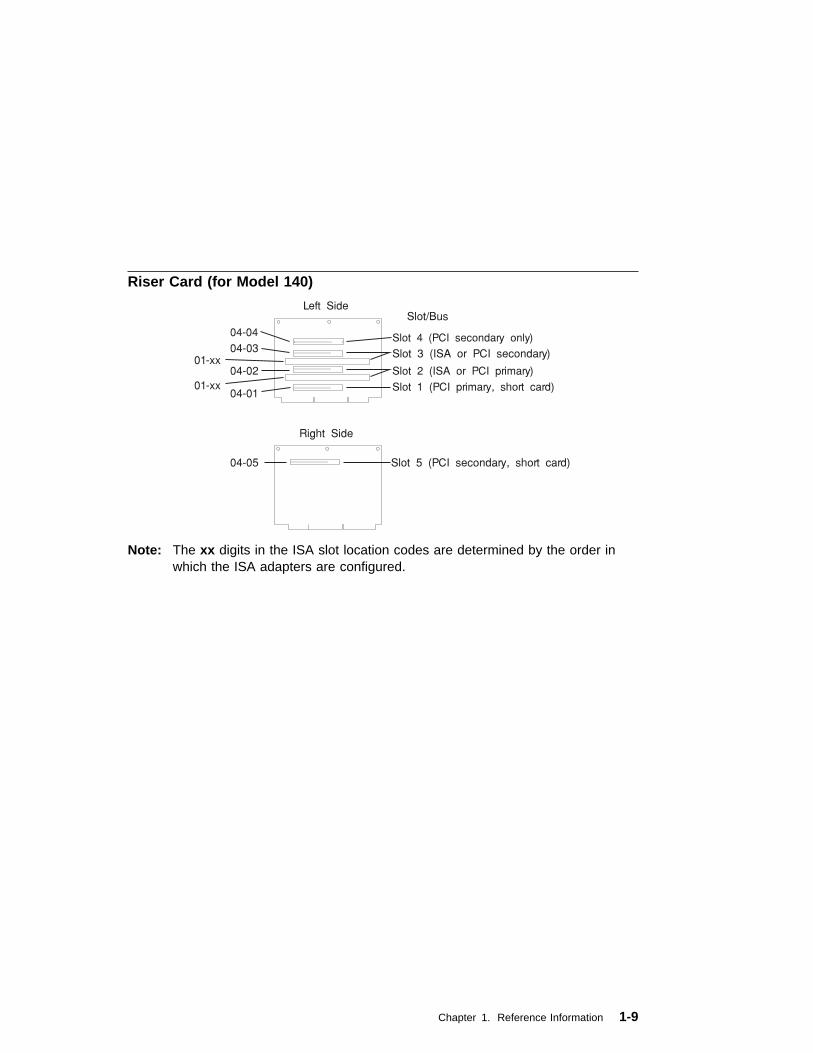
Riser Card (for Model 140)
Note: The xx digits in the ISA slot location codes are determined by the order inwhich the ISA adapters are configured.
Chapter 1. Reference Information 1-9

System Board Locations (for Model 150)
U82
J15 J44
J18J27J30
J1
J41J26
J40
J42
J43
J46J12
J14
J20
J53
J50J29J31
J35
J39
B1
J25
J2
J9
J10
J36
J4
J5J6
J7
J8
J16
J23
J24
J33
J32
J59 J56 J49 J45 J38 J22 J17 J13 J3
J139 J28J19 J11
1-10 7043 43P Series Service Guide

B1 Battery connector
J2 5x5 Auxiliary 5v connector
J3 Audio input connector
J4 Internal SCSI connector #2
J5 CD-ROM audio connector
J6 CD-ROM audio connector
J7 Power connector
J8 Power connector
J10 Media Fan connector
J11 Memory Connector 1
J13 Audio output connector
J15 Remote Power-up Jumper
J16 Diskette drive connector
J17 Microphone jack
J18 Reset Connector
J19 Memory Connector 3
J20 Power-on Password jumper
J22 Headphone jack
J23 Serial port connector 2
J24 Serial port connector 1
J25 Tablet port connector
J26 CPU fansink connector
J27 System fan connector
J28 Memory Connector 2
J30 System fan connector
J32 Priviliged-Access Passwordjumper
J33 Internal SCSI 16-bit connector
J35 SCSI security jumper
J36 SCSI security jumper
J38 External SCSI connector
J39 Riser card connector
J40 Power Switch connector
J41 Op Panel Connector
J42 Power Indicator LED connector
J43 Hard disk activity LED connector
J44 Voltage Regulator connector
J45 Ethernet twisted pair connector
J46 Internal Speaker connector
J49 Parallel port connector
J50 Ethernet AUI
J53 Ethernet EPROM connector
J56 Mouse port connector
J59 Keyboard port connector
J139 Memory Connector 4
Chapter 1. Reference Information 1-11

System Board Jumper Settings (for Model 150)
For a more complete description of the function of these jumpers, see the systemunit User's Guide .
Jumper Description Settings
J15 Remote Power-up Default: Remote power-up disabled.
To enable Remote power-up, placejumper on the two pins closest to therear of the system unit.
J32 Privileged-Access Password Default: disabled.
To enable the writing or changing ofthe privileged-access password, placejumper on the two pins closest to therear of the system unit.
J35, J36 SCSI Security Default: external SCSI enabled
To disable external SCSI connector,move the jumper on J35 to the fronttwo pins, and the jumper on J36 to theright two pins.
J20 Power-On Password Default: power-on password enabled(can be set).
To disable the power-on password (forinstance, if it has been forgotten), placejumper on the two rightmost pins.
1-12 7043 43P Series Service Guide

Riser Card (for Model 150)
Chapter 1. Reference Information 1-13

System Board Locations (for Model 240)
1-14 7043 43P Series Service Guide

J1 Audio input connector
J2 Audio output connector
J3 Microphone jack
J4 Headphone jack
J5 External SCSI connector
J6 Ethernet twisted pair connector
J7 Parallel port connector
J8 Mouse port connector
J9 Keyboard port connector
J10 Internal SCSI connector
J12 SCSI security jumpers
J13 Serial port 2 connector
J14 Serial port 1 connector
J15 CD-ROM audio connector
J17 Memory connector H (DIMM 7)
J18 Memory connector E (DIMM 4)
J19 Memory connector D (DIMM 3)
J20 Memory connector C (DIMM 2)
J21 Memory connector B (DIMM 1)
J22 Memory connector A (DIMM 0)
J23 Memory connector G (DIMM 6)
J24 Memory connector F (DIMM 5)
J25 Riser card connector
J26 Diskette drive connector
J27 Power connectors P1, P2
J28 Power-On Password overridejumper (change jumper position tobypass password)
J29 Remote power-up jumper
J30 Power connector P9 (aux 5V dcpower connector)
J31 Power switch connector
J32 Privileged-Access Passwordjumper
J33 Power connector P10
J34 Ethernet AUI
J35 Power connector P11
J36 RISC watch connector
J37 Riser card connector (64 bit PCI)
J38 Internal SCSI connector
J40 Media bay fan connector
J41 Speaker connector
J42 Fan connector
J43 Fan connector
J44 Power good and disk activity LEDconnector
U69 Microprocessor Connector 0
U68 Microprocessor Connector 1
Chapter 1. Reference Information 1-15

System Board Jumper Settings (for Model 240)
For a more complete description of the function of these jumpers, see the systemunit User's Guide .
Jumper Description Settings
J29 Remote power-up Default: Remote power-up disabled.
To enable Remote power-up, placejumper on the two leftmost pins.
J32 Privileged-Access Password Default: disabled.
To enable the writing or changing ofthe privileged-access password, placejumper on the two leftmost pins.
J12 SCSI Security Default: external SCSI enabled
To disable external SCSI connector,move the jumpers to the two pinsfarthest from the riser card.
J28 Power-On Password Default: power-on password enabled(can be set).
To disable the power-on password (forinstance, if it has been forgotten), placejumper on the two rightmost pins.
1-16 7043 43P Series Service Guide
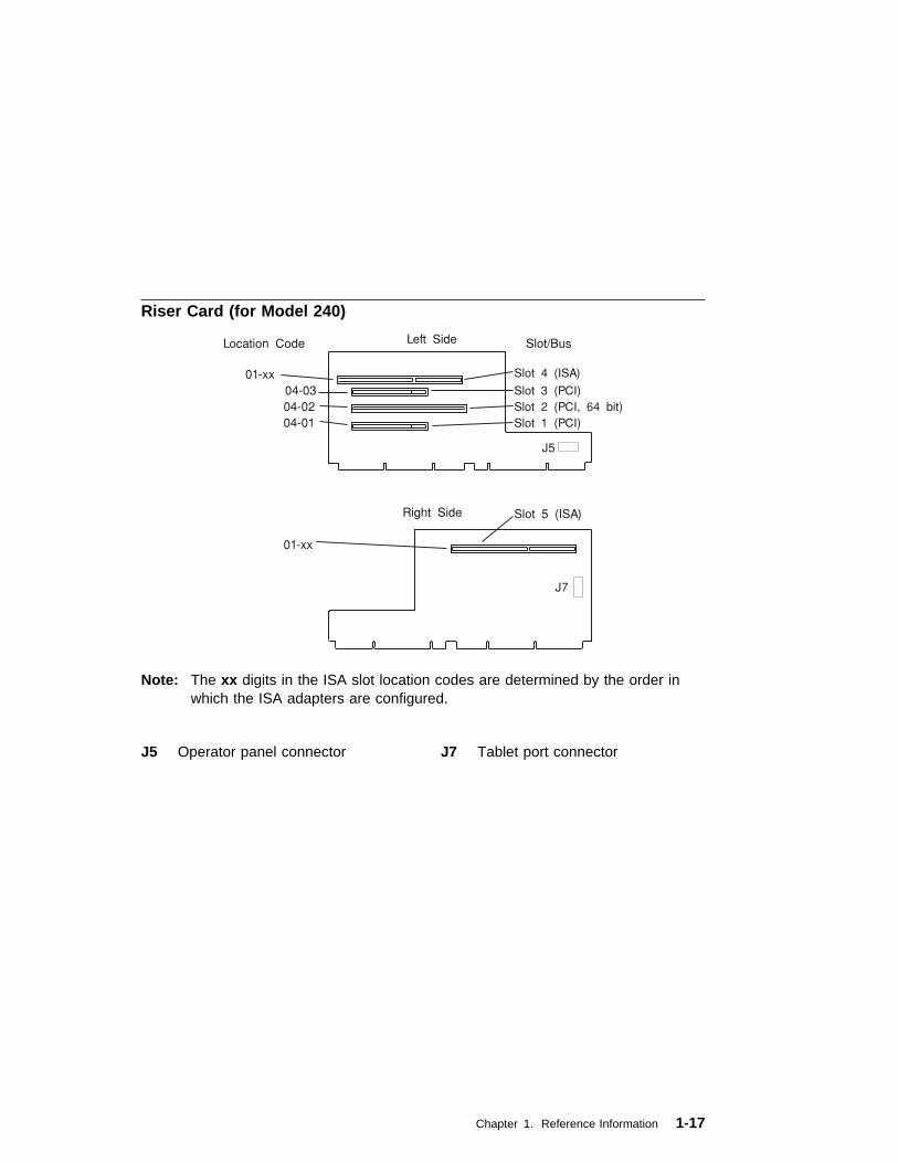
Riser Card (for Model 240)
Note: The xx digits in the ISA slot location codes are determined by the order inwhich the ISA adapters are configured.
J5 Operator panel connector J7 Tablet port connector
Chapter 1. Reference Information 1-17

SCSI Bus Termination
The Model 140 and Model 240 have a fast/wide SCSI-2 bus which can supportinternal and external SCSI devices. However, each controller on these SCSI bussesmust have a unique SCSI id, and the SCSI busses must be properly terminated bothinternally and externally (if external devices are used) to ensure SCSI signal integrity.
For directions on setting the SCSI id on each device, consult the documentation forthat device, as well as the Adapters, Devices, and Cable Information for Multiple BusSystems.
Model 140 Internal SCSI Bus Termination
The Model 140 internal SCSI chain must be terminated by the last drive in the chain,which must be configured as a self-terminating drive by setting jumpers on the drive.Please consult the documentation that came with your SCSI device.
Note: Only the last drive in each SCSI chain should be configured asself-terminating.
External SCSI chains must be terminated by a separate SCSI terminator.
Power Cables
To avoid electrical shock, a power cable with a grounded attachment plug isprovided. Use only properly grounded outlets.
Power cables used in the United States and Canada are listed by Underwriter'sLaboratories (UL) and certified by the Canadian Standards Association (CSA).These power cords consist of:
� Electrical cables, Type SVT or SJT.
� Attachment plugs complying with National Electrical Manufacturers Association(NEMA) 5-15P. That is:
"For 115 V operation, use a UL listed cable set consisting of a minimum 18 AWG,Type SVT or SJT three-conductor cord a maximum of 15 feet in length and a parallelblade, grounding type attachment plug rated at 15 A, 125 V."
"For 230 V operation in the United States use a UL listed cable set consisting of aminimum 18 AWG, Type SVT or SJT three-conductor cable a maximum of 15 feet inlength, and a tandem blade, grounding type attachment plug rated at 15 A, 250 V."
� Appliance couplers complying with International Electrotechnical Commission(IEC) Standard 320, Sheet C13.
1-18 7043 43P Series Service Guide
Power cables used in other countries consist of the following:
� Electrical cables, Type HD21.
� Attachment plugs approved by the appropriate testing organization for thespecific countries where they are used.
"For units set at 230 V (outside of U.S.): use a cable set consisting of a minimum 18AWG cable and grounding type attachment plug rated 15 A, 250 V. The cable setshould have the appropriate safety approvals for the country in which the equipmentwill be installed and should be marked HAR."
Refer to Chapter 9, “Parts Information” on page 9-1 to find the power cables that areavailable.
Service Inspection Guide
Perform a service inspection on the system when:
� The system is inspected for a maintenance agreement.
� Service is requested and service has not recently been performed.
� An alterations and attachments review is performed.
� Changes have been made to the equipment that may affect the safe operation ofthe equipment.
� External devices with separate power supplies have been attached.
If the inspection indicates an unacceptable safety condition, the condition must becorrected before anyone can service the machine.
Note: The correction of any unsafe condition is the responsibility of the owner of thesystem.
Perform the following checks:
1. Check the covers for sharp edges and for damage or alterations that expose theinternal parts of the system unit.
2. Check the covers for proper fit to the system unit. They should be in place andsecure.
3. Gently rock the system unit from side to side to determine if it is steady.
4. Set the power switch of the system unit to Off.
5. Disconnect the power cable.
6. Remove the covers.
Chapter 1. Reference Information 1-19

7. Check for alterations or attachments. If there are any, check for obvious safetyhazards such as broken wires, sharp edges, or broken insulation.
8. Check the internal cables for damage.
9. Check for dirt, water, and any other contamination within the system unit.
10. Check the voltage switch on the back of the system unit to ensure that itmatches the voltage at the outlet (Model 140 and M240. only.)
11. Check the external power cable for damage.
12. With the external power cable connected to the system unit, check for 0.1 ohmor less resistance between the ground lug on the external power cable plug andthe metal frame.
13. Perform the following checks on each device that has its own power cables:
a. Check for damage to the power cord.
b. Check for the correct grounded power cable.
c. With the external power cable connected to the device, check for 0.1 ohm orless resistance between the ground lug on the external power cable themetal frame of the device.
14. Install the covers.
1-20 7043 43P Series Service Guide

Chapter 2. Maintenance Analysis Procedures (MAPs)
This chapter contains Maintenance Analysis Procedures (MAPs) for the Model 140,Model 150, and Model 240.
Entry MAP
Notes:
1. When possible, run Online Diagnostics in Service Mode. Online Diagnosticsperform additional functions, compared to Standalone Diagnostics. This ensuresthat the error state of the system is captured in NVRAM for your use in fixing theproblem. The AIX error log and SMIT are only available when diagnostics arerun from the hard drive.
2. Licensed programs frequently rely on either network configuration, vital productdata (VPD) stored on the operator panel control assembly, or system boardinformation to authorize program use. If the MAPs indicate that the networkadapter, operator panel, or system board should be replaced, notify the systemowner that new keys for licensed programs may be required.
3. If a network adapter or the system board is replaced, the network administratormust be notified so that the client IP addresses used by the server can bechanged. In addition, the operating system configuration of the networkcontroller may need to be changed in order to enable system startup, and anyclient or server that addresses this system should be updated. After completingthe recommended actions in this chapter, go to "MAP 0410: Repair Checkout" inthe Diagnostics Information for Multiple Bus Systems.
Chapter 2. Maintenance Analysis Procedures (MAPs) 2-1

Quick Entry MAP
Use the following table to determine your starting point in the Entry Map.
Quick Entry MAP Table of Contents
Use the following table to determine your starting point.
Problem Description Page No.
Service Actions 2-2
System Stops or Hangs with Alternating Numbers Displayed in the OperatorPanel Display
2-2
System Stops With an Error or Checkpoint Code Displayed 2-2
There Appears to be a Display Problem (Distortion, Blurring, etc.) 2-3
Power and Cooling Problems 2-4
Other Symptoms or Problems 2-4
You Cannot Find the Symptom in this Table 2-6
Symptom Action
Service Actions
You have parts to exchange or a correctiveaction to perform.
1. Go to Chapter 8, “Removal andReplacement Procedures” on page 8-1.
2. Go to "MAP 0410: Repair Checkout" in theDiagnostics Information for Multiple BusSystems.
You need to verify that a part exchange orcorrective action corrected the problem.
Go to "MAP 0410: Repair Checkout" in theDiagnostics Information for Multiple BusSystems.
You need to verify correct system operation. Go to "MAP 0410: Repair Checkout" in theDiagnostics Information for Multiple BusSystems.
System Stops or hangs with alternating numbers displayed in the Operator Panel display.
The Operator Panel display alternates betweenthe code "E1FD" and another "Exxx" code.
Record both codes. Go to the entry for "E1FD"on page 4-23.
The Operator Panel display alternates betweenthe codes "E1DE" and "E1AD".
Record the error codes. Go to the entry for"E1DE" on page 4-21,
System Stops With an Error or Checkpoint Code Displayed
The system stops and an 8-digit error codestarting with the character "M" is displayed.
Record the error code. Go to “POST ErrorCodes” on page 3-2.
2-2 7043 43P Series Service Guide

Symptom Action
The system stops and an 8-digit error codestarting with the number "2" is displayed.
Record the error code. If you are working on aModel 140 or Model 240, go to “Firmware ErrorCodes” on page 3-4. If you are working on aModel 150, go to “Error Codes” on page 4-1.
The system stops and a 4-digit numberbeginning with the characters "FF" is displayedin the operator panel display.
Go to “MAP 1540: Minimum Configuration” onpage 2-21.
The system stops and a 4digit numberbeginning with the character "E" is displayed inthe operator panel display.
Record the code. Go to “Firmware Checkpoints”on page 4-13.
The system stops and a 4digit number notbeginning with neither the characters "FF" or "E"is displayed in the operator panel display.
Record SRN 101xxx, where xxx is the last threedigits of the fourdigit number displayed, then goto the "Fast Path MAP" in the DiagnosticsInformation for Multiple Bus Systems.
Note: If the operator panel displays 2 sets ofnumbers, use the bottom set of numbersas the error code.
The system stops and a 3-digit number isdisplayed in the operator panel display.
If the number displayed begins with thecharacter "F" then go to “Firmware Checkpoints”on page 3-14.
If the number is 000, 185, or 888, go to “MAP1540: Minimum Configuration” on page 2-21.
Record SRN 101-xxx, where xxx is the 3-digitnumber displayed in the operator panel display,then go to the "Fast Path MAP" in theDiagnostics Information for Multiple BusSystems.
888 is displayed in the control panel followed byadditional error codes.
Go to the Fast Path MAP in the DiagnosticsInformation for Multiple Bus Systems.
There Appears to be a Display Problem (Blank, Distortion, Blurring, Etc.)
Chapter 2. Maintenance Analysis Procedures (MAPs) 2-3
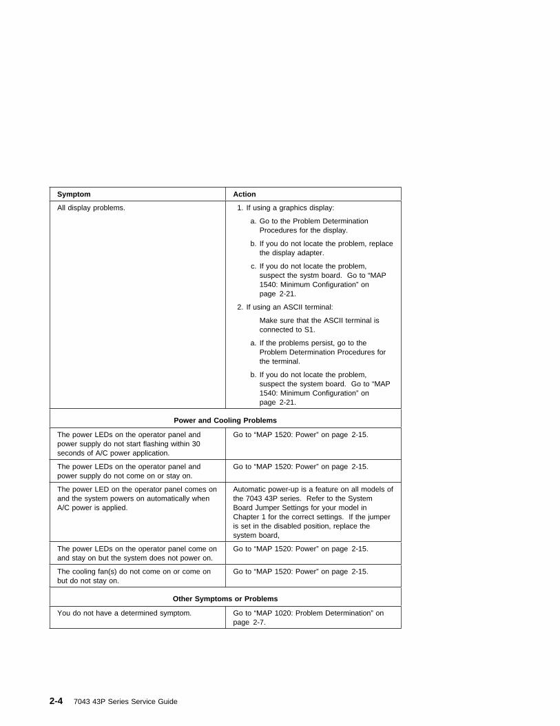
Symptom Action
All display problems. 1. If using a graphics display:
a. Go to the Problem DeterminationProcedures for the display.
b. If you do not locate the problem, replacethe display adapter.
c. If you do not locate the problem,suspect the systm board. Go to “MAP1540: Minimum Configuration” onpage 2-21.
2. If using an ASCII terminal:
Make sure that the ASCII terminal isconnected to S1.
a. If the problems persist, go to theProblem Determination Procedures forthe terminal.
b. If you do not locate the problem,suspect the system board. Go to “MAP1540: Minimum Configuration” onpage 2-21.
Power and Cooling Problems
The power LEDs on the operator panel andpower supply do not start flashing within 30seconds of A/C power application.
Go to “MAP 1520: Power” on page 2-15.
The power LEDs on the operator panel andpower supply do not come on or stay on.
Go to “MAP 1520: Power” on page 2-15.
The power LED on the operator panel comes onand the system powers on automatically whenA/C power is applied.
Automatic power-up is a feature on all models ofthe 7043 43P series. Refer to the SystemBoard Jumper Settings for your model inChapter 1 for the correct settings. If the jumperis set in the disabled position, replace thesystem board,
The power LEDs on the operator panel come onand stay on but the system does not power on.
Go to “MAP 1520: Power” on page 2-15.
The cooling fan(s) do not come on or come onbut do not stay on.
Go to “MAP 1520: Power” on page 2-15.
Other Symptoms or Problems
You do not have a determined symptom. Go to “MAP 1020: Problem Determination” onpage 2-7.
2-4 7043 43P Series Service Guide
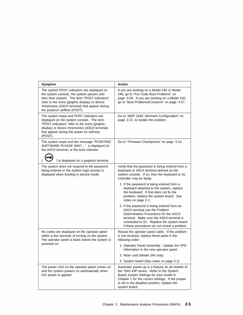
Symptom Action
The system POST indicators are displayed onthe system console, the system pauses andthen then restarts. The term "POST indicators"refer to the icons (graphic display) or devicemnemonics (ASCII terminal) that appear duringthe poweron selftest (POST).
If you are working on a Model 140 or Model240, go to “Fxx Code Boot Problems” onpage 3-18. If you are working on a Model 150,go to “Boot Problems/Concerns” on page 4-27.
The system stops and POST indicators aredisplayed on the system console. The term"POST indicators" refer to the icons (graphicdisplay) or device mnemonics (ASCII terminal)that appear during the power-on self-test(POST).
Go to “MAP 1540: Minimum Configuration” onpage 2-21. to isolate the problem.
The system stops and the message "STARTINGSOFTWARE PLEASE WAIT..." is displayed onthe ASCII terminal, or the boot indicator
( ) is displayed on a graphics terminal.
Go to “Firmware Checkpoints” on page 3-14.
The system does not respond to the passwordbeing entered or the system login prompt isdisplayed when booting in service mode.
Verify that the password is being entered from akeyboard or ASCII terminal defined as thesystem console. If so, then the keyboard or itscontroller may be faulty.
1. If the password is being entered from akeyboard attached to the system, replacethe keyboard. If that does not fix theproblem, replace the system board. Seenotes on page 2-1.
2. If the password is being entered from anASCII terminal use the ProblemDetermination Procedures for the ASCIIterminal. Make sure the ASCII terminal isconnected to S1. Replace the system boardif these procedures do not reveal a problem.
No codes are displayed on the operator panelwithin a few seconds of turning on the system.The operator panel is blank before the system ispowered on.
Reseat the operator panel cable. If the problemis not resolved, replace these parts in thefollowing order:
1. Operator Panel Assembly. Update the VPDinformation in the new operator panel.
2. Riser card (Model 240 only).
3. System board (See notes on page 2-1)
The power LED on the operator panel comes onand the system powers on automatically whenA/C power is applied.
Automatic power-up is a feature on all models ofthe 7043 43P series. Refer to the SystemBoard Jumper Settings for your model inChapter 1 for the correct settings. If the jumperis set in the disabled position, replace thesystem board,
Chapter 2. Maintenance Analysis Procedures (MAPs) 2-5
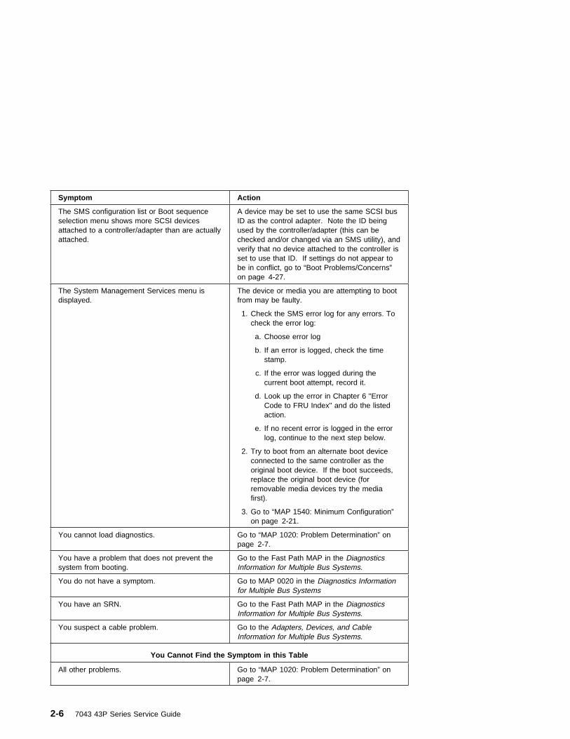
Symptom Action
The SMS configuration list or Boot sequenceselection menu shows more SCSI devicesattached to a controller/adapter than are actuallyattached.
A device may be set to use the same SCSI busID as the control adapter. Note the ID beingused by the controller/adapter (this can bechecked and/or changed via an SMS utility), andverify that no device attached to the controller isset to use that ID. If settings do not appear tobe in conflict, go to “Boot Problems/Concerns”on page 4-27.
The System Management Services menu isdisplayed.
The device or media you are attempting to bootfrom may be faulty.
1. Check the SMS error log for any errors. Tocheck the error log:
a. Choose error log
b. If an error is logged, check the timestamp.
c. If the error was logged during thecurrent boot attempt, record it.
d. Look up the error in Chapter 6 "ErrorCode to FRU Index" and do the listedaction.
e. If no recent error is logged in the errorlog, continue to the next step below.
2. Try to boot from an alternate boot deviceconnected to the same controller as theoriginal boot device. If the boot succeeds,replace the original boot device (forremovable media devices try the mediafirst).
3. Go to “MAP 1540: Minimum Configuration”on page 2-21.
You cannot load diagnostics. Go to “MAP 1020: Problem Determination” onpage 2-7.
You have a problem that does not prevent thesystem from booting.
Go to the Fast Path MAP in the DiagnosticsInformation for Multiple Bus Systems.
You do not have a symptom. Go to MAP 0020 in the Diagnostics Informationfor Multiple Bus Systems
You have an SRN. Go to the Fast Path MAP in the DiagnosticsInformation for Multiple Bus Systems.
You suspect a cable problem. Go to the Adapters, Devices, and CableInformation for Multiple Bus Systems.
You Cannot Find the Symptom in this Table
All other problems. Go to “MAP 1020: Problem Determination” onpage 2-7.
2-6 7043 43P Series Service Guide

MAP 1020: Problem Determination
Purpose of This MAP
Use this MAP to get an error code if you were not provided one by the customer oryou are unable to load diagnostics. If you are able to load the diagnostics, go toMAP 0020 in the Diagnostics Information for Multiple Bus Systems.
Be prepared to record code numbers and use those numbers in the course ofanalyzing a problem. Go to “Step 1020-1.”
Step 1020-1
The following steps analyze a failure to load the diagnostic programs.
Note: You are asked questions regarding the operator panel display. You are alsoasked to perform certain actions based on displayed POST indicators.Please be observant of these conditions.
1. Insert the diagnostic CD-ROM disc into the CD-ROM drive.
2. Turn the power off.
3. Turn the power on.
4. If the keyboard indicator is displayed (the word keyboard on an ASCII terminalor the keyboard and hand icon on a graphical display), press the F5 key on thedirectly-attached keyboard or the number 5 key on an ASCII terminal.
Chapter 2. Maintenance Analysis Procedures (MAPs) 2-7

5. Enter any requested passwords.
6. Wait until the diagnostics are loaded or the system appears to stop.
7. Find your symptom in the following table; then follow the instructions given in theAction column.
Symptom Action
The disk LED is blinking rapidly, or EIEA, EIEB,FEA, or FEB is displayed on the operator panel.
The flash EPROM data is corrupted. Therecovery procedure for the flash EPROM shouldbe executed. See “Firmware Recovery” onpage 7-25.
The system stops with a prompt to enter apassword.
Enter the password. You will not be allowed tocontinue until a correct password has beenentered. When you have entered a validpassword go to the beginning of this table andwait for one of the other conditions to occur.
The diagnostics loaded. Go to MAP 0020 in the Diagnostics Informationfor Multiple Bus Systems.
The system login prompt is displayed. You may not have pressed the correct key oryou may not have pressed the key soon enoughwhen you were to indicate a Service Mode IPLof the diagnostic programs. If this was the casestart over at the beginning of this Step.
Note: Perform the systems shutdownprocedure before turning off the system.
If you are sure you pressed the correct key in atimely manner, go to “Step 1020-2” onpage 2-10.
The system does not respond when thepassword is entered.
Go to “Step 1020-2” on page 2-10.
The system stopped and a POST indicator isdisplayed on the system console and aneight-digit error code is not displayed.
If the POST indicator represents:
� memory, record error code M0MEM002.
� keyboard, record error code M0KBD000.
� SCSI, record error code M0CON000.
� network, record error code M0NET000.
� speaker (audio), record error codeM0BT0000.
Go to “Step 1020-3” on page 2-10.
The system stops and an 8-digit error codestarting with the character "M" is displayed.
Record the error code. Go to “POST ErrorCodes” on page 3-2.
The system stops and an 8-digit error codestarting with the number "2" is displayed.
Record the error code. If you are working on aModel 140 or Model 240, go to “Firmware ErrorCodes” on page 3-4. If you are working on aModel 150, go to “Error Codes” on page 4-1.
2-8 7043 43P Series Service Guide
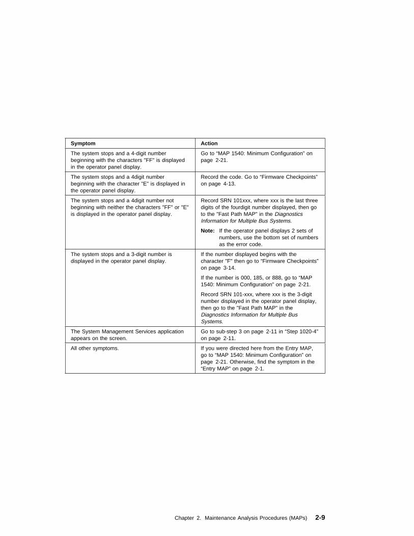
Symptom Action
The system stops and a 4-digit numberbeginning with the characters "FF" is displayedin the operator panel display.
Go to “MAP 1540: Minimum Configuration” onpage 2-21.
The system stops and a 4digit numberbeginning with the character "E" is displayed inthe operator panel display.
Record the code. Go to “Firmware Checkpoints”on page 4-13.
The system stops and a 4digit number notbeginning with neither the characters "FF" or "E"is displayed in the operator panel display.
Record SRN 101xxx, where xxx is the last threedigits of the fourdigit number displayed, then goto the "Fast Path MAP" in the DiagnosticsInformation for Multiple Bus Systems.
Note: If the operator panel displays 2 sets ofnumbers, use the bottom set of numbersas the error code.
The system stops and a 3-digit number isdisplayed in the operator panel display.
If the number displayed begins with thecharacter "F" then go to “Firmware Checkpoints”on page 3-14.
If the number is 000, 185, or 888, go to “MAP1540: Minimum Configuration” on page 2-21.
Record SRN 101-xxx, where xxx is the 3-digitnumber displayed in the operator panel display,then go to the "Fast Path MAP" in theDiagnostics Information for Multiple BusSystems.
The System Management Services applicationappears on the screen.
Go to sub-step 3 on page 2-11 in “Step 1020-4”on page 2-11.
All other symptoms. If you were directed here from the Entry MAP,go to “MAP 1540: Minimum Configuration” onpage 2-21. Otherwise, find the symptom in the“Entry MAP” on page 2-1.
Chapter 2. Maintenance Analysis Procedures (MAPs) 2-9

Step 1020-2
There is a problem with the keyboard.
Find the type of keyboard you are using in the following table; then follow theinstructions given in the Action column.
Step 1020-3
Take the following actions:
1. If you are working on a Model 140 or Model 240, find the eight-digit error code inChapter 3, “Error Code to FRU Index for the Model 140 and Model 240” onpage 3-1. If you are working on a Model 150, find the eight-digit error code inChapter 4, “Error Code to FRU Index for the Model 150” on page 4-1.
Note: If the eight-digit error code is not listed in Chapter 3, “Error Code to FRUIndex for the Model 140 and Model 240” or Chapter 4, “Error Code to FRU Indexfor the Model 150,” look for it in the following:
� Any supplemental service manual for the device
� The diagnostic problem report screen for additional information
� The Service Hints service aid
� The CEREADME file (by using the Service Hints service aid).
Note: Service aids can be found in the Diagnostics Information for Multiple BusSystems.
2. Perform the action listed.
Keyboard Type Action
Type 101 keyboard (U.S.). Identify by the size ofthe Enter key. The Enter key is in only onehorizontal row of keys.
Record error code M0KBD001; then go to“Step 1020-3.”
Type 102 keyboard (W.T.). Identify by the size ofthe Enter key. The Enter key extends into twohorizontal rows.
Record error code M0KBD002; then go to“Step 1020-3.”
Type 106 keyboard. (Identify by the Japanesecharacters.)
Record error code M0KBD003; then go to“Step 1020-3.”
ASCII terminal keyboard Go to the documentation for this type of ASCIIterminal and continue problem determination.
2-10 7043 43P Series Service Guide

Step 1020-4
1. Turn off, then turn on the system unit.
2. When the keyboard indicator appears, press the F1 key on a directly attachedkeyboard or the 1 key on an ASCII terminal.
3. When the System Management Services appear, check the error log for anyerrors.
� Choose Utilities
� Choose Error Log
� If an error is logged, check the time stamp.
� If the error was logged during the current boot attempt, record it.
� If you are working on a Model 140 or Model 240, look up the error in theChapter 3, “Error Code to FRU Index for the Model 140 and Model 240” onpage 3-1 and do the listed action. If you are working on a Model 150, lookup the error in the Chapter 4, “Error Code to FRU Index for the Model 150”on page 4-1 and do the listed action.
� If no recent error is logged in the error log, go to “MAP 1540: MinimumConfiguration” on page 2-21.
Chapter 2. Maintenance Analysis Procedures (MAPs) 2-11

MAP 1240: Memory Problem Resolution
Purpose of This MAP
Note: The firmware checkpoint that sent you here could be one of the following:E122, E213, E214, E220 or E3xx.
These checkpoints are referred to as "a memory checkpoint" in this MAP.
Use this MAP to trouble shoot a problem during the memory test when the systemstops at a memory checkpoint and no error code is displayed on the system console.
General Memory Information
Be sure to unplug the power cable before removing or installing the memory modulesto avoid damage to them.
Model 150 memory modules do not need to be installed in pairs and can be installedin any slot on the system board. There is no requirement that one slot be installedbefore the other.
Refer to “Memory Modules” on page 8-20 for locations of the memory modules andinstructions on module removal and installation.
Note: If the symptom changes, check for loose cards, cables, and obviousproblems. If you do not find the problem, go to “MAP 1540: Minimum Configuration”on page 2-21.
Step 1240-1
1. Ensure that the diagnostics and the operating system are shut down.
2. Power off the system. Refer to "Powering Off the System".
3. Remove and re-install any installed memory module(s).
4. Power on the system. Refer to "Powering On the System".
Does the system stop with a memory checkpoint displayed on the operatorpanel?
NO Reseating the memory modules has corrected the problem.
Go to "MAP 0410: Repair Checkout" in the Diagnostics Information forMultiple Bus Systems.
2-12 7043 43P Series Service Guide

YES If there is only one memory module installed, go to “Step 1240-3” onpage 2-13.
If there is more than one memory module installed, go to “Step 1240-2.”
Step 1240-2
1. Power off the system. Refer to "Powering Off the System".
2. Remove all but one of the installed memory modules. Record the position of thememory modules removed so that when instructed to re-install them, they can beinstalled in their original positions.
3. Power on the system. Refer to "Powering On the System".
Does the system stop with a memory checkpoint displayed on the operatorpanel?
NO Repeat this step until all the memory modules have been installed andtested.
If all the memory modules have been installed, reseating the memorymodules has corrected the problem.
Go to "MAP 0410: Repair Checkout" in the Diagnostics Information forMultiple Bus Systems.
YES Go to “Step 1240-3.”
Step 1240-3
The failure may be caused by the last memory module installed or the system board.To isolate the failing FRU do the following:
1. Power off the system. Refer to "Powering Off the System".
2. Exchange the last memory module installed.
3. Power on the system. Refer to "Powering On the System".
Does the system stop with a memory checkpoint displayed on the operatorpanel?
NO Go to "MAP 0410: Repair Checkout" in the Diagnostics Information forMultiple Bus Systems.
YES Go to “Step 1240-4” on page 2-14.
Chapter 2. Maintenance Analysis Procedures (MAPs) 2-13

Step 1240-4
One of the FRUs remaining in the system unit is defective.
1. Power off the system. Refer to "Powering Off the System".
2. Exchange the following FRUS in the order listed:
a. System Board
b. Power Supply
3. Power on the system. Refer to "Powering On the System".
Does the system stop with a memory checkpoint displayed on the operatorpanel?
NO Go to "MAP 0410: Repair Checkout" in the Diagnostics Information forMultiple Bus Systems.
YES Reinstall the original FRU.
Repeat this step until the defective FRU is identified or all the FRUs havebeen exchanged.
If the symptom did not change and all the FRUs have been exchanged,go to “MAP 1540: Minimum Configuration” on page 2-21.
2-14 7043 43P Series Service Guide

MAP 1520: Power
Notes:
1. This is not a start of call MAP. Use this Power MAP only if you have beendirected here from a MAP step in the Diagnostics Information for Multiple BusSystems.
2. The Model 150 has a power LED located on the operator panel. When thesystem is powered on the LED should be on solid.
This procedure is used to locate power problems in system units. If a problem isdetected, this procedure helps you isolate the problem to a failing unit.
Observe the following safety notice during service procedures.
DANGER
An electrical outlet that is not correctly wired could place hazardousvoltage on metal parts of the system or the devices that attach to thesystem. It is the responsibility of the customer to ensure that the outletis correctly wired and grounded to prevent and electrical shock.
Before installing or removing signal cables, ensure that the powercables for the system unit and all attached devices are unplugged.
When adding or removing any additional devices to or from the system,ensure that the power cables for those devices are unplugged beforethe signal cables are connected. You must disconnect all power cablesfrom the existing system before you add a device.
Use one hand, when possible, to connect or disconnect signal cablesto prevent a possible shock from touching two surfaces with differentelectrical potentials.
During an electrical storm, do not connect cables for display stations,printers, telephones, or station protectors for communication lines.
CAUTION:This product is equipped with a three–wire power cable and plug for the user'ssafety. Use this power cable with a properly grounded electrical outlet to avoidelectrical shock.
Chapter 2. Maintenance Analysis Procedures (MAPs) 2-15
Step 1520-1
You may be directed to this MAP for several reasons:
1. There is no indication of activity when the power button is pressed. None of theLEDs light and none of the fans, including the fan in the power supply, start toturn.
Go to “Step 1520-2.”
2. When the power switch is pressed, the system begins to power on, but thepower does not stay on.
Go to “Step 1520-3” on page 2-17.
Step 1520-2
1. Turn the power off.
2. Check that the voltage selection switch on the power supply is in the correctposition.
3. Check that the external power cable to the system unit has continuity.
4. Check that the power outlet has been wired correctly with the correct voltage.
5. Check that the external power cable is plugged into both the system unit and thepower outlet.
Did you find a problem?
NO Go to “Step 1520-3” on page 2-17.
YES Correct the problem. Go to "Map 0410: Repair Checkout" in theDiagnostics Information for Multiple Bus Systems.
2-16 7043 43P Series Service Guide

Step 1520-3
1. Turn the power off.
2. Unplug the system unit power cable from the electrical outlet.
3. Remove external cables (keyboard, mouse, etc.)
4. Remove the top cover.
5. Record the slot numbers of all the installed adapters. Label and record thelocation of any cables attached to the adapters. Remove all the adapters.
6. Remove all the memory modules.
7. Remove the processor cards (Model 240 only).
8. Remove the L2 cache card (Model 140 only).
9. Remove the riser card and SCSI cables from the system board.
10. Unplug the diskette drive signal cable and diskette drive power cable from thesystem board.
11. Unplug the power cables from all the SCSI devices.
12. Unplug internal serial port and Ethernet cable from the system board.
13. Unplug the front fans and media fan.
14. Unplug the speaker.
Note: Do not disconnect the power-on LED or the power switch.
15. Connect the system unit power cable to the electrical outlet.
16. Turn the power on.
Does the fan in the power supply turn on and the power LED come on and stayon?
NO Go to “Step 1520-4” on page 2-18.
YES Go to “Step 1520-5” on page 2-19.
Chapter 2. Maintenance Analysis Procedures (MAPs) 2-17

Step 1520-4
Note: Either the power supply, the system board, or the power switch is defective.
To test each FRU, exchange the FRUs that have not already been exchanged in thefollowing order.
� Power supply
� Power Switch
� System board (See notes on 2-1.)
1. Turn the power off.
2. Unplug the system unit power cable from the wall outlet.
3. Exchange one of the FRUs in the list.
4. Connect the system unit power cable to the wall outlet.
5. Turn the power on.
Does the fan in the power supply turn on and the power LED come on and stayon?
NO Reinstall the original FRU.
Repeat this step until the defective FRU is identified.
YES Go to "Map 0410: Repair Checkout" in the Diagnostics Information forMultiple Bus Systems.
2-18 7043 43P Series Service Guide
Step 1520-5
One of the parts that was removed or unplugged is causing the problem. Install orconnect the parts in the following order.
1. Fans
2. Riser card
3. Processor cards (Model 240 only)
4. L2 cache card (Model 140 only)
5. Memory modules
6. System board cables
7. Diskette power cable
8. SCSI power cable, lowest bay to highest bay.
9. Adapter cards, lowest slot to highest slot.
Turn the power on after each part is installed or connected. If the system does notpower on or the power does not stay on, the most recently installed or connectedpart is causing the failure.
1. Turn the power off.
2. Unplug the system unit power cable from the wall outlet.
3. Install or connect one of the parts in the list.
4. Connect the system unit power cable to the wall outlet.
5. Turn the power on.
Chapter 2. Maintenance Analysis Procedures (MAPs) 2-19

Does the fan in the power supply turn on and the power LED come on and stayon?
NO Replace the last part you installed. (If this part was a network adapter,see notes on 2-1.)
Repeat these steps until all the parts have been installed.
If the symptom did not change and all the parts have been replaced, callyour service support person for assistance.
If the symptom has changed, check for loose cards, cables, and obviousproblems. If you do not find a problem, return to “Step 1520-1” onpage 2-16 in this MAP and follow the instructions for the new symptom.
YES Repeat these steps until all the parts have been installed.
Go to "Map 0410: Repair Checkout" in the Diagnostics Information forMultiple Bus Systems.
2-20 7043 43P Series Service Guide

MAP 1540: Minimum Configuration
Note: If you were sent to this MAP from the Diagnostics Information for Multiple BusSystems as a result of an SRN 101-xxx problem, go to “Fxx Code BootProblems” on page 3-18 and follow the instructions there before using theMAP 1540 steps.
Purpose of this MAP
This MAP is used to locate defective FRUs not found by normal diagnostics. For thisprocedure, diagnostics are run on a minimally-configured system. If a failure isdetected on the minimally-configured system, the remaining FRUs are exchangedone at a time until the failing FRU is identified. If a failure is not detected, FRUs areadded back until the failure occurs. The failure is then isolated to the failing FRU.
Notes:
1. This MAP assumes that a CD-ROM drive is installed and connected to theintegrated SCSI adapter, and a Diagnostics CD-ROM disc is available.
2. If a power-on password or privileged-access password is installed, you areprompted to enter the password before the diagnostic CD-ROM loads.
3. The term "POST indicators" refer to the icons (graphic display) or devicemnemonics (ASCII terminal) that appear during the power-on self-test (POST).
Because the minimum configurations for the Model 140 and Model 240 differ, thisMAP is divided into 1540A for the Model 140 and 1540B for the Model 240.
� MAP 1540A: Minimum Configuration (for the Model 140 and Model 150) beginson 2-22.
� MAP 1540B: Minimum Configuration (for the Model 240) begins on 2-39.
Chapter 2. Maintenance Analysis Procedures (MAPs) 2-21

MAP 1540A: Minimum Configuration (for the Model 140 and Model 150)
Step 1540A-1
1. Ensure that the diagnostics and the operating system are shut down.
2. Turn the power off.
3. Turn the power on.
4. Insert the diagnostic CD-ROM into the CD-ROM drive.
5. When the keyboard indicator is displayed (the word keyboard on an ASCIIterminal or the keyboard and hand icon on a graphical display), press the F5 keyon the directly-attached keyboard or the number 5 key on an ASCII terminal.
6. If the Console Selection screen is displayed, choose the system console.
7. Enter the appropriate password when prompted to do so.
Is the "Please define the System Console" screen displayed?
NO Go to “Step 1540A-2” on page 2-23.
YES Go to “Step 1540A-13” on page 2-35.
2-22 7043 43P Series Service Guide

Step 1540A-2
1. Turn the power off.
2. Disconnect all external cables.
3. Remove the top cover.
4. Record the slot numbers of any adapter cards installed in the system unit. Labeland record the location of any cables attached to the adapters. Remove all theadapters from the system unit.
5. Record the slot numbers of the memory modules, and then remove all but thememory module in memory slot A (DIMM 0) on the Model 140, or DIMM 1 on theModel 150.
6. Remove the L2 cache card. (Model 140 only)
7. Disconnect the SCSI cable from the SCSI connectors on the system board.
8. Disconnect the diskette drive cable from the diskette drive connector on thesystem board.
9. Disconnect the internal serial, ethernet, and tablet port cables.
10. Turn the power on.
Does the operator panel do one of the following:
� Stop with any code other than
– FDC, FF2, FF3, or F4D (Model 140)
– E1DC, E1F2, E1F3, E1F7, or E14D (Model 150)
� Alternate between
– FFD and any other code (Model 140)
– E1FD and any other code (Model 150)
NO Go to “Step 1540A-4” on page 2-25.
YES Go to “Step 1540A-3” on page 2-24.
Chapter 2. Maintenance Analysis Procedures (MAPs) 2-23

Step 1540A-3
One of the FRUs remaining in the system unit is defective.
1. Turn the power off.
2. Exchange one of the FRUs in the following list.
a. System board (See notes on 2-1.)
b. Riser card
c. Memory module
3. Turn the power on.
Does the operator panel do one of the following:
� Stop with any code other than
– FDC, FF2, FF3, or F4D (Model 140)
– E1DC, E1F2, E1F3, E1F7, or E14D (Model 150)
� Alternate between
– FFD and any other code (Model 140)
– E1FD and any other code (Model 150)
NO Go to "Map 0410: Repair Checkout" in the Diagnostics Information forMultiple Bus Systems.
YES Reinstall the original FRU.
Repeat the FRU replacement steps until the defective FRU is identified orall the FRUs have been exchanged.
If the symptom did not change and all the FRUs have been exchanged,call your service support person for assistance.
If the symptom has changed, check for loose cards, cables, and obviousproblems. If you do not find a problem, return to “Step 1540A-1” onpage 2-22 in this MAP and follow the instructions for the new symptom.
2-24 7043 43P Series Service Guide
Step 1540A-4
No failure was detected with this configuration.
1. Turn the power off.
2. Install a memory module.
3. Turn the power on.
Does the operator panel do one of the following:
� Stop with any code other than
– FDC, FF2, FF3, or F4D (Model 140)
– E1DC, E1F2, E1F3, E1F7, or E14D (Model 150)
� Alternate between
– FFD and any other code (Model 140)
– E1FD and any other code (Model 150)
NO Repeat this step until all the memory modules are installed and tested.
After all the memory modules are installed and tested, turn the power tooff.
For Model 140, go to “Step 1540A-7 (Model 140 only)” on page 2-28.
For Model 150 or Model 240, go to “Step 1540A-8” on page 2-29.
YES Go to “Step 1540A-5” on page 2-26.
Chapter 2. Maintenance Analysis Procedures (MAPs) 2-25

Step 1540A-5
The failure may be caused by the last memory module installed. To isolate the failingFRU, do the following:
1. Turn the power off.
2. Exchange the last memory module installed.
3. Turn the power on.
Does the operator panel do one of the following:
� Stop with any code other than
– FDC, FF2, FF3, or F4D (Model 140)
– E1DC, E1F2, E1F3, E1F7, or E14D (Model 150)
� Alternate between
– FFD and any other code (Model 140)
– E1FD and any other code (Model 150)
NO Go to "Map 0410: Repair Checkout" in the Diagnostics Information forMultiple Bus Systems.
YES Go to “Step 1540A-6” on page 2-27.
2-26 7043 43P Series Service Guide
Step 1540A-6
One of the FRUs remaining in the system unit is defective.
1. Turn the power off.
2. Exchange one of the FRUs in the following list.
� System board (See notes on 2-1.)
� Power supply.
3. Turn the power on.
Does the operator panel do one of the following:
� Stop with any code other than
– FDC, FF2, FF3, or F4D (Model 140)
– E1DC, E1F2, E1F3, E1F7, or E14D (Model 150)
� Alternate between
– FFD and any other code (Model 140)
– E1FD and any other code (Model 150)
NO Go to "Map 0410: Repair Checkout" in the Diagnostics Information forMultiple Bus Systems.
YES Reinstall the original FRU.
Repeat this step until the defective FRU is identified or all the FRUs havebeen exchanged.
If the symptom did not change and all the FRUs have been exchanged,call your service support person for assistance.
If the symptom has changed, check for loose cards, cables, and obviousproblems. If you do not find a problem, return to “Step 1540A-1” onpage 2-22 in this MAP, and follow the instructions for the new symptom.
Chapter 2. Maintenance Analysis Procedures (MAPs) 2-27

Step 1540A-7 (Model 140 only)
1. Turn the power off.
2. Install the L2 cache card.
Does the operator panel do one of the following:
� Stop with any code other than
– FDC, FF2, FF3, or F4D (Model 140)
� Alternate between
– FFD and any other code (Model 140)
NO The system board or L2 cache card is defective.
1. Replace the L2 cache card and repeat this step.
2. Replace the system board and install the original L2 cache card andrepeat this step.
3. Replace the L2 cache card and repeat this step.
4. If the symptom did not change and both the system board and L2cache card have been replaced, call your service support person forassistance.
See notes on 2-1 regarding system board replacement.
YES Go to “Step 1540A-8” on page 2-29.
2-28 7043 43P Series Service Guide

Step 1540A-8
1. Turn the power off.
2. Reconnect the system console.
Notes:
a. If an ASCII terminal has been defined as the system console, attach theASCII terminal cable to the S1 connector on the rear of the system unit. Alsoconnect the internal serial and Ethernet cables to the system board.
b. If a display attached to a display adapter has been defined as the systemconsole, install the display adapter and connect the display to it. Plug thekeyboard into the keyboard connector on the rear of the system unit.
3. Turn the power on.
4. If the ASCII terminal or graphics display (including display adapter) areconnected differently than before, the Console Selection screen will appear andrequire that a new console be selected.
5. When the keyboard indicator is displayed, press the F1 key on the directlyattached keyboard or the number 1 key on an ASCII terminal. This triggers theSMS.
6. Enter the appropriate password when prompted to do so.
7. Wait until the SMS screen is displayed or the system appears to stop.
Chapter 2. Maintenance Analysis Procedures (MAPs) 2-29

Is the SMS screen displayed?
NO One of the FRUs remaining in the system unit is defective.
In the following order, exchange the FRUs that have not been exchanged:
1. Go to the Problem Determination Procedures (test procedures) for thedevice attached to the S1 serial port or the display attached to thegraphics adapter, and test those devices. If a problem is found,follow the procedures for correcting the problem on that device.
2. Graphics adapter (if installed).
3. Cable (async or graphics, including internal async cable).
4. Riser card
5. System board (See notes on 2-1.)
Repeat this step until the defective FRU is identified or all the FRUs havebeen exchanged.
If the symptom did not change and all the FRUs have been exchanged,call your service support person for assistance.
If the symptom changed, check for loose cards and obvious problems. Ifyou do not find a problem, return to “Step 1540A-1” on page 2-22 andfollow the instructions for the new symptom.
YES Go to “Step 1540A-9” on page 2-31.
2-30 7043 43P Series Service Guide

Step 1540A-9
1. Make sure the diagnostic CD-ROM is inserted into the CD-ROM drive.
2. Turn the power off.
3. Plug the SCSI cable into the SCSI connector on the system board.
4. Disconnect the signal and power connectors from all the SCSI devices exceptthe CD-ROM drive.
5. Make sure that the SCSI chain is still properly terminated; see “SCSI BusTermination” on page 1-18.
6. Turn the power on.
7. After the keyboard indicator is displayed, press the F5 key on thedirectly-attached keyboard or the number 5 key on an ASCII terminal keyboard.
8. Enter the appropriate password when prompted to do so.
Is the "Please define the System Console" screen displayed?
NO One of the FRUs remaining in the system unit is defective.
In the following order, exchange the FRUs that have not been exchanged:
1. SCSI cable termination (see “SCSI Bus Termination” on page 1-18)
2. SCSI cable
3. Last SCSI device connected (CD-ROM drive, tape drive, etc.)
4. The graphics adapter, if the system console is defined as a graphicaldisplay.
5. The riser card.
6. System board (See notes on page 2-1.)
7. Power Supply
Repeat this step until the defective FRU is identified or all the FRUs havebeen exchanged.
If the symptom did not change and all the FRUs have been exchanged,call your service support person for assistance.
If the symptom has changed, check for loose cards, cables, and obviousproblems. If you do not find a problem, return to “Step 1540A-1” onpage 2-22 in this MAP and follow the instructions for the new symptom.
Chapter 2. Maintenance Analysis Procedures (MAPs) 2-31

YES Repeat this step, adding one SCSI device at a time, until all the SCSI devices that were attached to the integrated SCSIadapter are connected and tested.
Go to “Step 1540A-10.”
Step 1540A-10
The system is working correctly with this configuration. One of the FRUs (adapters)that you removed is probably defective.
1. Make sure the diagnostic CD-ROM disc is inserted into the CD-ROM drive.
2. Turn the power off.
3. Plug the diskette drive cable into the diskette drive connector on the systemboard.
4. Turn the power on.
5. After the keyboard indicator is displayed, press the F5 key on thedirectly-attached keyboard or the number 5 key on an ASCII terminal keyboard.
6. Enter the appropriate password when prompted to do so.
Is the "Please define the System Console" screen displayed?
NO One of the FRUs remaining in the system is defective.
In the following order, exchange the FRUs that have not been exchanged.
1. Diskette drive2. Diskette drive cable3. System board (See notes on page 2-1.)
4. Power supply
Repeat this step until the defective FRU is identified or all the FRUs havebeen exchanged.
If the symptom did not change and all the FRUs have been exchanged,call your service support person for assistance.
If the symptom has changed check for loose cards, cables, and obviousproblems. If you do not find a problem return to “Step 1540A-1” onpage 2-22 in this MAP and follow the instructions for the new symptom.
YES Go to “Step 1540A-11” on page 2-33.
2-32 7043 43P Series Service Guide

Step 1540A-11
The system is working correctly with this configuration. One of the FRUs (adapters)that you removed is probably defective,
1. Turn the power off.
2. Install a FRU (adapter) and connect any cables and devices, if any, that wereattached to it.
3. Turn the power on.
4. Make sure the diagnostic CD-ROM disc is inserted into the CD-ROM drive.
5. If the Console Selection screen is displayed, choose the system console.
6. After the keyboard indicator is displayed, press the F5 key on thedirectly-attached keyboard or the number 5 key on an ASCII terminal keyboard.
7. Enter the appropriate password when prompted to do so.
Is the "Please define the System Console" screen displayed?
NO Go to “Step 1540A-12” on page 2-34.
YES Repeat this step until all of the FRUs (adapters) are installed, then go tothe Repair Checkout Procedure in the Diagnostics Information for MultipleBus Systems.
Chapter 2. Maintenance Analysis Procedures (MAPs) 2-33

Step 1540A-12
1. Make sure the diagnostic CD-ROM disc is inserted into the CD-ROM drive.
2. Turn the power off.
3. Starting with the last installed adapter, if there are any devices and cablesattached to it, disconnect one attached device and cable.
4. Turn the power on.
5. If the Console Selection screen is displayed, choose the system console.
6. After the keyboard indicator begins blinking, press the F5 key on thedirectly-attached keyboard or the number 5 key on an ASCII terminal keyboard.
7. Enter the appropriate password when prompted to do so.
Is the "Please define the System Console" screen displayed?
NO Repeat this step until the defective device or cable, if any were attached,is identified or all the devices and cables have been disconnected.
If all the devices and cables have been removed, or there were noneattached, then one of the FRUs remaining in the system unit is defective.
To test each FRU, exchange the FRUs in the following order:
1. Adapter (last one installed) 2. Riser card 3. System board 4. Power supply
If a network adapter or system board is replaced, see notes on page 2-1.
If the symptom did not change and all the FRUs have been exchanged,call your service support person for assistance.
Repeat this step until all of the FRUs have been exchanged.
If the symptom has changed check for loose cards, cables, and obviousproblems. If you do not find a problem return to “Step 1540A-1” onpage 2-22 in this MAP and follow the instructions for the new symptom.
YES The last device or cable that you disconnected or the last FRU that youexchanged is defective.
Exchange the defective FRU, device or cable.
Go to "Map 0410: Repair Checkout" in the Diagnostics Information forMultiple Bus Systems.
2-34 7043 43P Series Service Guide
Step 1540A-13
1. Follow the instructions on the screen to select the system console.
2. When the DIAGNOSTIC OPERATING INSTRUCTIONS screen is displayed,press Enter.
3. If the terminal type has not been defined, you must use the Initial Terminal optionon the FUNCTION SELECTION menu to initialize the AIX operating systemenvironment before you can continue with the diagnostics. This is a separate anddifferent operation than selecting the console display.
4. Select Advance Diagnostics Routines.
5. If the NEW RESOURCE screen displays, select an option from the bottom of thescreen.
Note: Adapters or devices that require supplemental media are not shown inthe new resource list. If the system has adapters or devices that require asupplemental media, select option 1.
6. When the DIAGNOSTIC MODE SELECTION screen is displayed, press Enter.
7. Select All Resources (if you were sent here from “Step 1540A-17” on page 2-37,select the Adapter/Device you loaded from the supplemental media).
Did you get an SRN?
NO Go to “Step 1540A-15” on page 2-37.
YES Go to “Step 1540A-14” on page 2-36.
Chapter 2. Maintenance Analysis Procedures (MAPs) 2-35

Step 1540A-14
Look at the FRU part numbers associated with the SRN.
Have you exchanged all the FRUs that correspond to the failing functioncodes?
NO Exchange the FRU with the highest failure percentage that has not beenchanged.
Repeat this step until all the FRUs associated with the SRN have beenexchanged or diagnostics run with no trouble found. Run diagnostics aftereach FRU is exchanged.
If a network adapter or system board is replaced, see notes on page 2-1.
Go to "Map 0410: Repair Checkout" in the Diagnostics Information forMultiple Bus Systems.
YES If the symptom did not change and all the FRUs have been exchanged,call your service support person for assistance.
2-36 7043 43P Series Service Guide

Step 1540A-15
Does the system have adapters or devices that require supplemental media?
NO Go to “Step 1540A-16.”
YES Go to “Step 1540A-17.”
Step 1540A-16
Consult the PCI adapter configuration documentation for your operating system toverify that all installed adapters are configured correctly.
Go to "MAP 0410: Repair Checkout" in the Diagnostics Information for Multiple BusSystems.
If the symptom did not change and all the FRUs have been exchanged, call yourservice support person for assistance.
Step 1540A-17
Select TASK SELECTION.
Select Process Supplemental Media and follow the on screen instructions to processthe media.
Supplemental media must be loaded and processed one at a time.
Did the system return to the TASK SELECTION list after the supplementalmedia was processed?
NO Go to “Step 1540A-18” on page 2-38.
YES Press F3 to return to the FUNCTION SELECTION screen.
Go to “Step 1540A-13” substep 4 on page 2-35.
Chapter 2. Maintenance Analysis Procedures (MAPs) 2-37
Step 1540A-18
The adapter or device is probably defective.
If the supplemental media is for an adapter replace the FRUs in the following order:
1. Adapter
2. Riser card
3. System board.
If the supplemental media is for a device replace the FRUs in the following order:
1. Device and any associated cables
2. The adapter the device is attached to.
Repeat this step until the defective FRU is identified or all the FRUs have beenexchanged.
If the symptom did not change and all the FRUs have been exchanged, call yourservice support person for assistance.
If the symptom has changed, check for loose cards, cables, and obvious problems.If you do not find a problem, return to “Step 1540A-1” on page 2-22 for the newsymptom.
Go to "MAP 0410: Repair Checkout" in the Diagnostics Information for Multiple BusSystems.
2-38 7043 43P Series Service Guide

MAP 1540B: Minimum Configuration (for the Model 240)
Step 1540B-1
1. Ensure that the diagnostics and the operating system are shut down.
2. Insert the diagnostic CD-ROM into the CD-ROM drive.
3. Turn the power off.
4. Turn the power on.
5. When the keyboard indicator is displayed (the word keyboard on an ASCIIterminal or the keyboard and hand icon on a graphical display), press the F5 keyon the directly-attached keyboard or the number 5 key on an ASCII terminal.
6. If the Console Selection screen is displayed, choose the system console.
7. Enter the appropriate password when prompted to do so.
Is the "Please define the System Console" screen displayed?
NO Go to “Step 1540B-2” on page 2-40.
YES Go to “Step 1540B-12” on page 2-50.
Chapter 2. Maintenance Analysis Procedures (MAPs) 2-39

Step 1540B-2
1. Turn the power off.
2. Disconnect all external cables.
3. Remove the top cover.
4. Record the slot numbers of the ISA and PCI adapters. Label and record thelocation of any cables attached to the adapters. Remove all the adapters.
5. Remove the second processor card.
6. Record the slot numbers of the memory modules, and then remove all but onepair of the memory modules in memory slots A and B (DIMMs 0 and 1).
7. Disconnect the SCSI cable from the SCSI connectors on the system board.
8. Disconnect the diskette drive cable from the diskette drive connector on thesystem board.
9. Disconnect the internal serial, Ethernet, and tablet port cables.
10. Turn the power on.
Does the operator panel stabilize for more than 60 seconds with code FDC,FF2, FF3, or F4D displayed, or is one of these codes displayed immediatelybefore the system unit attempts to restart?
NO Go to “Step 1540B-3” on page 2-41.
YES Go to “Step 1540B-4” on page 2-42.
2-40 7043 43P Series Service Guide

Step 1540B-3
One of the FRUs remaining in the system unit is defective.
If the following steps call for a system board to be replaced, see notes on page 2-1.
1. If the disk LED is on, turn the power off and exchange the following FRUs inorder:
a. Memory modules (pair)
b. Riser card
c. System board (See notes on page 2-1)
2. If the disk LED is off, turn the power off and exchange the following FRUs inorder:
a. Processor cards
b. Memory modules (pair)
c. Riser card
d. System board (See notes on page 2-1)
Does the operator panel stabilize for more than 60 seconds with code FDC,FF2, FF3, or F4D displayed, or is one of these codes displayed immediatelybefore the system unit attempts to restart?
NO Reinstall the original FRU.
Repeat the FRU replacement steps until the defective FRU is identified orall the FRUs have been exchanged.
If the symptom did not change and all the FRUs have been exchanged,call your service support person for assistance.
If the symptom has changed, check for loose cards, cables, and obviousproblems. If you do not find a problem, return to “Step 1540B-1” onpage 2-39 in this MAP and follow the instructions for the new symptom.
YES Go to "Map 0410: Repair Checkout" in the Diagnostics Information forMultiple Bus Systems.
Chapter 2. Maintenance Analysis Procedures (MAPs) 2-41

Step 1540B-4
No failure was detected with this configuration.
1. Turn the power off.
2. Install a pair memory modules.
3. Turn the power on.
Does the operator panel stabilize for more than 60 seconds with code FDC,FF2, FF3, or F4D displayed, or is one of these codes displayed immediatelybefore the system unit attempts to restart?
NO Go to “Step 1540B-5.”
YES Repeat this step until all the memory modules are installed and tested.
After all the memory modules are installed and tested, turn the power tooff.
Go to “Step 1540B-7” on page 2-44.
Step 1540B-5
The failure may be caused by the last pair of memory modules installed. To isolatethe failing FRU, do the following:
1. Turn the power off.
2. Exchange the last memory module pair installed.
3. Turn the power on.
Does the operator panel stabilize for more than 60 seconds with code FDC,FF2, FF3, or F4D displayed, or is one of these codes displayed immediatelybefore the system unit attempts to restart?
NO Go to “Step 1540B-6” on page 2-43.
YES Go to "Map 0410: Repair Checkout" in the Diagnostics Information forMultiple Bus Systems.
2-42 7043 43P Series Service Guide

Step 1540B-6
One of the FRUs remaining in the system unit is defective.
1. Turn the power off.
2. Exchange the following FRUs the order listed.
a. System board (See notes on page 2-1)
b. Power supply
3. Turn the power on.
Does the operator panel stabilize for more than 60 seconds with code FDC,FF2, FF3, or F4D displayed, or is one of these codes displayed immediatelybefore the system unit attempts to restart?
NO Reinstall the original FRU.
Repeat this step until the defective FRU is identified or all the FRUs havebeen exchanged.
If the symptom did not change and all the FRUs have been exchanged,call your service support person for assistance.
If the symptom has changed, check for loose cards, cables, and obviousproblems. If you do not find a problem, return to “Step 1540B-1” onpage 2-39 in this MAP, and follow the instructions for the new symptom.
YES Go to "Map 0410: Repair Checkout" in the Diagnostics Information forMultiple Bus Systems.
Chapter 2. Maintenance Analysis Procedures (MAPs) 2-43

Step 1540B-7
1. Turn the power off.
2. Reconnect the system console.
Notes:
a. If an ASCII terminal has been defined as the system console, attach theASCII terminal cable to the S1 connector on the rear of the system unit. Alsoconnect the internal serial and Ethernet cables to the system board.
b. If a display attached to a display adapter has been defined as the systemconsole, install the display adapter and connect the display to it. Plug thekeyboard into the keyboard connector on the rear of the system unit.
3. Turn the power on.
4. If the ASCII terminal or graphics display (including display adapter) areconnected differently than before, the Console Selection screen appears andrequires that a new console be selected.
5. When the keyboard indicator is displayed, press the F1 key on the directlyattached keyboard or the number 1 key on an ASCII terminal. This triggers theSMS.
6. Enter the appropriate password when prompted to do so.
7. Wait until the SMS screen is displayed or the system appears to stop.
2-44 7043 43P Series Service Guide
Is the SMS screen displayed?
NO One of the FRUs remaining in the system unit is defective.
In the following order, exchange the FRUs that have not been exchanged:
1. Go to the Problem Determination Procedures (test procedures) for thedevice attached to the S1 serial port or the display attached to thegraphics adapter, and test those devices. If a problem is found,follow the procedures for correcting the problem on that device.
2. Graphics adapter (if installed).
3. Cable (async or graphics, including internal async cable).
4. Riser card.
5. System board. (See notes on page 2-1.)
Repeat this step until the defective FRU is identified or all the FRUs havebeen exchanged.
If the symptom did not change and all the FRUs have been exchanged,call your service support person for assistance.
If the symptom changed, check for loose cards and obvious problems. Ifyou do not find a problem, return to “Step 1540B-1” on page 2-39 andfollow the instructions for the new symptom.
YES Go to “Step 1540B-8” on page 2-46.
Chapter 2. Maintenance Analysis Procedures (MAPs) 2-45

Step 1540B-8
1. Make sure the diagnostic CD-ROM is inserted into the CD-ROM drive.
2. Turn the power off.
3. Plug the internal SCSI cable into both SCSI connectors on the system board.
4. Disconnect the signal and power connectors from all the SCSI devices exceptthe CD-ROM drive.
5. Make sure the SCSI chain is properly terminated; see “SCSI Bus Termination” onpage 1-18.
6. Turn the power on.
7. After the keyboard indicator is displayed, press the F5 key on thedirectly-attached keyboard or the number 5 key on an ASCII terminal keyboard.
8. Enter the appropriate password when prompted to do so.
Is the "Please define the System Console" screen displayed?
NO One of the FRUs remaining in the system unit is defective.
In the following order, exchange the FRUs that have not been exchanged:
1. SCSI cable
2. Last SCSI device connected (CD-ROM drive, tape drive, etc.)
3. The graphics adapter, if the system console is defined as a graphicaldisplay.
4. Riser card
5. System board (See notes on page 2-1)
6. Processor card
7. Power Supply
Repeat this step until the defective FRU is identified or all the FRUs havebeen exchanged.
If the symptom did not change and all the FRUs have been exchangedcall your service support person for assistance.
If the symptom has changed check for loose cards, cables, and obviousproblems. If you do not find a problem return to “Step 1540B-1” onpage 2-39 in this MAP and follow the instructions for the new symptom.
2-46 7043 43P Series Service Guide

YES Repeat this step, adding one SCSI device at a time, until all the SCSIdevices that were attached to the integrated SCSI adapter are connectedand tested.
Go to “Step 1540B-9.”
Step 1540B-9
The system is working correctly with this configuration. One of the FRUs (adapters)that you removed is probably defective.
1. Make sure the diagnostic CD-ROM disc is inserted into the CD-ROM drive.
2. Turn the power off.
3. Plug the diskette drive cable into the diskette drive connector on the systemboard.
4. Turn the power on.
5. After the keyboard indicator is displayed, press the F5 key on thedirectly-attached keyboard or the number 5 key on an ASCII terminal keyboard.
6. Enter the appropriate password when prompted to do so.
Is the "Please define the System Console" screen displayed?
NO One of the FRUs remaining in the system is defective.
In the following order, exchange the FRUs that have not been exchanged.
1. Diskette drive2. Diskette drive cable3. System board (See notes on page 2-1)
4. Power supply
Repeat this step until the defective FRU is identified or all the FRUs havebeen exchanged.
If the symptom did not change and all the FRUs have been exchanged,call your service support person for assistance.
If the symptom has changed check for loose cards, cables, and obviousproblems. If you do not find a problem return to “Step 1540B-1” onpage 2-39 in this MAP and follow the instructions for the new symptom.
YES Go to “Step 1540B-10” on page 2-48.
Chapter 2. Maintenance Analysis Procedures (MAPs) 2-47

Step 1540B-10
The system is working correctly with this configuration. One of the FRUs (adapters)that you removed is probably defective.
1. Turn the power off.
2. Install the second processor card if one was removed. If a second processor wasnot removed, or has already been reinstalled and verified, install a FRU (adapter)and connect any cables and devices that were attached to it.
3. Turn the power on.
4. If the Console Selection screen is displayed, choose the system console.
5. After the keyboard indicator is displayed, press the F5 key on thedirectly-attached keyboard or the number 5 key on an ASCII terminal keyboard.
6. Enter the appropriate password when prompted to do so.
Is the "Please define the System Console" screen displayed?
NO Go to “Step 1540B-11” on page 2-49.
YES Repeat this step until all of the FRUs (adapters) are installed, then go tothe Repair Checkout Procedure in the Diagnostics Information for MultipleBus Systems.
2-48 7043 43P Series Service Guide

Step 1540B-11
The last FRU installed or one of its attached devices is probably defective.
1. Make sure the diagnostic CD-ROM disc is inserted into the CD-ROM drive.
2. Turn the power off.
3. Starting with the last installed adapter, disconnect one attached device andcable.
4. Turn the power on.
5. If the Console Selection screen is displayed, choose the system console.
6. After the keyboard indicator appears, press the F5 key on the directly-attachedkeyboard or the number 5 key on an ASCII terminal keyboard.
7. Enter the appropriate password when prompted to do so.
Is the "Please define the System Console" screen displayed?
NO Repeat this step until the defective device or cable is identified or all thedevices and cables have been disconnected.
If all the devices and cables have been removed, then one of the FRUsremaining in the system unit is defective.
To test each FRU, exchange the FRUs in the following order:
1. Adapter (last one installed) 2. Riser card
3. System board. (If the system board or a network adapter is replaced,see notes on page 2-1.)
4. Power supply
If the symptom did not change and all the FRUs have been exchanged,call your service support person for assistance.
If the symptom has changed check for loose cards, cables, and obviousproblems. If you do not find a problem return to “Step 1540B-1” onpage 2-39 in this MAP and follow the instructions for the new symptom.
YES The last device or cable that you disconnected is defective. Exchangethe defective device or cable.
Go to "Map 0410: Repair Checkout" in the Diagnostics Information forMultiple Bus Systems.
Chapter 2. Maintenance Analysis Procedures (MAPs) 2-49

Step 1540B-12
1. Follow the instructions on the screen to select the system console.
2. When the DIAGNOSTIC OPERATING INSTRUCTIONS screen is displayed,press Enter.
3. If the terminal type has not been defined, you must use the Initial Terminal optionon the FUNCTION SELECTION menu to initialize the AIX operating systemenvironment before you can continue with the diagnostics. This is a separate anddifferent operation than selecting the console display.
4. Select Advanced Diagnostic Routines.
5. If the NEW RESOURCE screen displays, select an option from the bottom of thescreen.
Note: Adapters or devices that require supplemental media are not shown inthe new resource list. If the system has adapters or devices that require asupplemental media, select option 1.
6. When DIAGNOSTIC MODE SELECTION screen is displayed, press Enter.
7. Select All Resources (if you were sent here from “Step 1540A-17” on page 2-37,select the Adapter/Device you loaded from the supplemental media).
Did you get an SRN?
NO Go to “Step 1540B-14” on page 2-51.
YES Go to “Step 1540B-13” on page 2-51.
2-50 7043 43P Series Service Guide

Step 1540B-13
Look at the FRU part numbers associated with the SRN.
Have you exchanged all the FRUs that correspond to the failing functioncodes?
NO Exchange the FRU with the highest failure percentage that has not beenchanged.
Repeat this step until all the FRUs associated with the SRN have beenexchanged or diagnostics run with no trouble found. Run diagnostics aftereach FRU is exchanged.
If the system board or a network adapter is replaced, see notes on page2-1.
Go to "Map 0410: Repair Checkout" in the Diagnostics Information forMultiple Bus Systems.
YES If the symptom did not change and all the FRUs have been exchanged,call your service support person for assistance.
Step 1540B-14
Does the system have adapters or devices that require supplemental media?
NO Go to “Step 1540B-15” on page 2-52.
YES Go to “Step 1540B-16” on page 2-52.
Chapter 2. Maintenance Analysis Procedures (MAPs) 2-51

Step 1540B-15
Consult the ISA and PCI adapter configuration documentation for your operatingsystem to verify that all installed adapters are configured correctly.
Go to "MAP 0410: Repair Checkout" in the Diagnostics Information for Multiple BusSystems.
If the symptom did not change and all the FRUs have been exchanged, call yourservice support person for assistance.
Step 1540B-16
Select TASK SELECTION.
Select Process Supplemental Media and follow the on screen instructions to processthe media.
Supplemental media must be loaded and processed one at a time.
Did the system return to the TASK SELECTION list after the supplementalmedia was processed?
NO Go to “Step 1540B-17” on page 2-53.
YES Press F3 to return to the FUNCTION SELECTION screen.
Go to “Step 1540B-12” substep 4 on page 2-50.
2-52 7043 43P Series Service Guide

Step 1540B-17
The adapter or device is probably defective.
If the supplemental media is for an adapter replace the FRUs in the following order:
1. Adapter.
2. Riser card
3. System board
If the supplemental media is for a device replace the FRUs in the following order:
1. Device and any associated cables.
2. The adapter the device is attached to.
Repeat this step until the defective FRU is identified or all the FRUs have beenexchanged.
If the symptom did not change and all the FRUs have been exchanged, call yourservice support person for assistance.
If the symptom has changed, check for loose cards, cables, and obvious problems.If you do not find a problem, return to “Step 1540B-1” on page 2-39 for the newsymptom.
Go to "MAP 0410: Repair Checkout" in the Diagnostics Information for Multiple BusSystems.
Chapter 2. Maintenance Analysis Procedures (MAPs) 2-53

2-54 7043 43P Series Service Guide

Chapter 3. Error Code to FRU Index for the Model 140 andModel 240
Note: For Error Code and Checkpoint information for the Model 150, seeChapter 4, “Error Code to FRU Index for the Model 150” on page 4-1.
The Error Code to FRU Index lists error symptoms and possible causes. The mostlikely cause is listed first. Use this index to help you decide which FRUs to replacewhen servicing the system.
If the codes in the following tables indicate a device which is present more than oncein the system unit, a location code is needed to specify which device generated theerror. Go to “Step 1020-4” on page 2-11 to display the System ManagementServices error log and obtain a location code. Location code descriptions can befound under “Firmware Location Codes” on page 3-21.
If you replace FRUs and the problem is still not unresolved, go to “MAP 1540:Minimum Configuration” on page 2-21 unless otherwise indicated in the tables. Ifyou replace FRUs and the problem has been resolved, go to "MAP 0410: RepairCheckout" in the Diagnostics Information for Multiple Bus Systems unless otherwiseindicated in the tables.
Notes:
1. Licensed programs frequently rely on network configuration or system boardinformation to authorize program use. If the following tables indicate that thesystem board or network adapter should be replaced, notify the system ownerthat new keys for licensed programs may be required.
2. If a network adapter or the system board is replaced, the network administratormust be notified so that the client IP addresses used by the server can bechanged. In addition, the operating system configuration of the network controllermay need to be changed in order to enable system startup.
Chapter 3. Error Code to FRU Index for Model 140 and Model 240 3-1

POST Error Codes
Table 3-1 (Page 1 of 2). POST Error Codes
Error Code Description Action/Possible Failing FRU
M0CON000 The system hung during POST. Go to “MAP 1540: MinimumConfiguration” on page 2-21.
M0CPU000 The CPU POST failed. 1. CPU Card (Model 240)2. System Board (See
notes on 3-1.)
M0CPU001 Checkstop occurred. 1. CPU card (Model 240)2. System board (See notes
on 3-1.)
M0FD0000 The system hung during diskette POST. 1. System board (See noteson 3-1.)
2. Diskette drive.
M0GA0000 Graphics adapter POST failed. Graphics adapter
M0HD0000 The system hung during boot POST. Go to “MAP 1540: MinimumConfiguration” on page 2-21.
M0KBD000 The system hung during keyboard POST. 1. System board (See noteson 3-1.)
2. Keyboard
M0KBD001 The system did not respond to a keyboard entry. Type 101 keyboard
M0KBD002 The system did not respond to a keyboard entry. Type 102 keyboard
M0KBD003 The system did not respond to a keyboard entry. Type 106 keyboard
M0MC0001 A machine check occurred. Go to “MAP 1540: MinimumConfiguration” on page 2-21.
M0MEM000 No good memory could be found. 1. Memory2. System board (See notes
on page 3-1.)
Note: If only one memorymodule is installed, (or pairfor a Model 240), replace it.If there are multiple memorymodules installed, go to“MAP 1540: MinimumConfiguration” on page 2-21.
M0MEM001 No good memory could be found. 1. Memory
2. System board. (Seenotes on page 3-1.)
M0MEM002 The system hung during memory POST. Go to “MAP 1540: MinimumConfiguration” on page 2-21.
M0PS0000 Power failure. Go to “MAP 1520: Power” onpage 2-15.
3-2 7043 43P Series Service Guide

Table 3-1 (Page 2 of 2). POST Error Codes
Error Code Description Action/Possible Failing FRU
M0SCSI00 Unable to load diagnostics. Go to “MAP 1540: MinimumConfiguration” on page 2-21.
M0SCSI01 Unable to load diagnostics. Go to “MAP 1540: MinimumConfiguration” on page 2-21.
M0SPK000 A continuous beep is heard from the system. System board (See notes onpage 3-1.)
M0SPK001 The system does not beep. 1. Speaker 2. System board. (See
notes on page 3-1.)
M0BT0000 Speaker (audio) error Record the code displayedon the operator panel. If thecode is listed in “FirmwareCheckpoints” on page 3-14then perform the indicatedaction. If the code is notlisted, go to “MAP 1540:Minimum Configuration” onpage 2-21.
M0NET000 Network error Record the code displayedon the operator panel. If thecode is listed in “FirmwareCheckpoints” on page 3-14then perform the indicatedaction. If the code is notlisted, go to “MAP 1540:Minimum Configuration” onpage 2-21.
Chapter 3. Error Code to FRU Index for Model 140 and Model 240 3-3

Firmware Error Codes
If you replace FRUs and the problem is still not corrected, go to MAP 0030 in theDiagnostics Information for Multiple Bus Systems unless otherwise indicated in thetables.
Table 3-2 (Page 1 of 9). Firmware Error Codes.
Error Code Description Action/Possible Failing FRU
20100xxx Power Supply
20A80xxx Remote initial program load (RIPL)error
xxx=000 Insufficient information to boot. Verify the IP address.
001 Client IP address is already in use byother network device
Change IP address.
002 Cannot get gateway IP address Refer to “Firmware Checkpoints” onpage 3-14 table using code F74.
003 Cannot get server hardware address Refer to “Firmware Checkpoints” onpage 3-14 table using code F74.
004 Bootp failed Refer to “Firmware Checkpoints” onpage 3-14 table using code F75.
005 File transmission (TFTP) failed Check network connection, try again.
20D00xxx Unknown/Unrecognized device
xxx=00F Self-test failed on device, noSRN/location code information available
Check the System ManagementServices error log entry (if present) forthe location code of the failing device.The error log is described in “Step1020-4” on page 2-11
If the error code specifies a networkadapter, see 3-1.
010 Self-test failed on device, can't locatepackage.
Contact your service supportrepresentative for assistance.
20E00xxx Security
xxx=000 Power on Password entry error. Retry installing the password.
001 Privileged-access password entry error. Retry installing the password.
002 Privileged-access password jumper notenabled.
The privileged-access password jumperis not in the correct position forpassword initial entry.
Consult the system's User's Guide forjumper location and position.
3-4 7043 43P Series Service Guide

Table 3-2 (Page 2 of 9). Firmware Error Codes.
Error Code Description Action/Possible Failing FRU
003 Power on Password must be set forUnattended mode
Unattended mode requires the settingof the Power On password before canbe enabled.
004 Battery drained or needs replacement 1. Replace battery.
2. Replace system board. (See noteson page 3-1.)
005 EEPROM locked 1. Turn off, then turn on system unit.
2. Replace the system board. (Seenotes on page 3-1.)
008 CMOS corrupted or tampering evident,CMOS initialized
Check your machine for evidence oftampering.
If no tampering evident:
1. Replace battery, restore NVRAMdata (passwords, startup data)
2. Replace system board. (See noteson page 3-1.)
009 Invalid password entered - systemlocked
The password has been enteredincorrectly 3 times.
Turn off, then turn on the system unit,then enter the password correctly.
00A EEPROM lock problem If for priviliged-access password install,is jumper in correct position?
Consult the system's User's Guide forjumper location and position.
1. Turn off, turn on system unit.
2. Replace system board. (See noteson page 3-1.)
00B EEPROM write problem 1. Turn off, turn on system unit.
2. Replace system board. (See noteson page 3-1.)
00C EEPROM read problem 1. Turn off, turn on system unit.
2. Replace system board. (See noteson page 3-1.)
017 Cold boot needed for password entry Turn off, turn on system unit.
20EE0xxx Informational
xxx=003 SMS: Invalid RIPL IP address (requires3 dots ".")
Enter valid RIPL IP address.
Example: 000.000.000.000
Chapter 3. Error Code to FRU Index for Model 140 and Model 240 3-5

Table 3-2 (Page 3 of 9). Firmware Error Codes.
Error Code Description Action/Possible Failing FRU
004 SMS: Invalid RIPL IP address Enter valid RIPL IP address.
Example: 000.000.000.000
005 SMS: Invalid portion of RIPL IPaddress (>255)
Enter valid RIPL IP address.
Example: 255.192.002.000
006 SMS: No SCSI controllers present The system board should always have(at least) an integrated PCI SCSIcontroller; replace system board.
See notes on page 3-1. regardingsystem board replacement.
007 Console Selection: Keyboard not found 1. Plug in keyboard
2. Replace system board (See noteson page 3-1.)
008 No configurable adapters found in thesystem
This warning occurs when the selectedSMS function cannot locate anydevices/adapters supported by thefunction. If a supported device isinstalled:
1. Replace the device or adapter
2. Replace riser card
3. Replace system board
21A00xxx SCSI disk drive 1. Before replacing any systemcomponents:
a. Ensure that the controller andeach device on the SCSI bus isassigned a unique SCSI ID.
b. Ensure SCSI bus is properlyterminated. See “SCSI BusTermination” on page 1-18.
c. Ensure SCSI signal and powercables are securely connectedand not damaged.
2. The location code information isrequired to identify the ID of SCSIdevice failures as well as toindicate the location of thecontroller to which the device isattached.
xxx=001 Test Unit Ready Failed - hardwareerror
1. SCSI device 2. SCSI cable
3. SCSI controller. If on systemboard, see 3-1.
3-6 7043 43P Series Service Guide

Table 3-2 (Page 4 of 9). Firmware Error Codes.
Error Code Description Action/Possible Failing FRU
002 Test Unit Ready Failed - sense dataavailable
1. Media (Removable media devices) 2. SCSI device
003 Send Diagnostic Failed 1. SCSI device
004 Send Diagnostic Failed - DevOfl cmd 1. SCSI device
21E00xxx SCSI Tape Refer to 21A00xxx (SCSI disk drive) forxxx definitions
21ED0xxx SCSI Changer Refer to 21A00xxx (SCSI disk drive) forxxx definitions
21EE0xxx Other SCSI device type Refer to 21A00xxx (SCSI disk drive) forxxx definitions
21F00xxx SCSI CDROM Refer to 21A00xxx (SCSI disk drive) forxxx definitions
21F20xxx SCSI Read/Write Optical Refer to 21A00xxx (SCSI disk drive) forxxx definitions
25010xxx Flash
xxx=000 No diskette in drive Insert diskette containing firmwareimage.
001 Diskette seek error 1. Retry function
2. Replace diskette drive
3. Replace diskette cable
4. Replace system board (See noteson page 3-1.)
002 Diskette in drive does not contain an*.IMG file.
Insert diskette with firmware update file.
003 Cannot open OPENPROM package Replace system board. (See notes onpage 3-1.)
004 Cannot find OPENPROM node Replace system board. (See notes onpage 3-1.)
006 System id does not match imagesystem id
Make sure correct firmware updatediskette is being used with this system.
007 Image has bad CRC Replace firmware updated diskette
008 Flash is write protected, updatecancelled
1. Turn off, turn on system unit andretry.
2. Replace system board. (See noteson page 3-1.)
009 Flash module is unsupported or notrecognized
Make sure correct firmware updatediskette is being used with this system.
Chapter 3. Error Code to FRU Index for Model 140 and Model 240 3-7

Table 3-2 (Page 5 of 9). Firmware Error Codes.
Error Code Description Action/Possible Failing FRU
00A Flash write protected. 1. Turn off, turn on system unit, retry.
2. Replace system board. (See noteson page 3-1.)
25A0xxy0 Cache: L2 controller failure Refer to error code 2B2xxyrr for adescription of the “xx” and “y” values.
For Model 140:
1. L2 Cache2. System board (See notes on page
3-1.)
For Model 240:
1. Processor card2. System board (See notes on page
3-1.)
25A1xxy0 Cache: L2 SRAM failure Refer to Error code 2B2xxyrr for adescription of the “xx” and “y” values.
For Model 140:
1. L2 Cache2. System board (See notes on page
3-1.)
For Model 240:
1. Processor card2. System board (See notes on page
3-1.)
25A80xxx NVRAM Note: Errors reported against NVRAMcan be caused by low Battery voltageand (more rarely) power outages thatoccur during normal system usage.With the exception of the 25A80000error, these errors are warnings thatthe NVRAM data content had to bere-established and do not require anyFRU replacement unless the error ispersistent. When one of these errorsoccurs, any system customization (eg.boot device list) information has beenlost, the system may need to bereconfigured.
If the error is persistent, replace thebattery.
If the error is persistent after batteryreplacement, or the error code is25A80000, replace the system board.(See notes on page 3-1.)
3-8 7043 43P Series Service Guide

Table 3-2 (Page 6 of 9). Firmware Error Codes.
Error Code Description Action/Possible Failing FRU
xxx=000 Initialization failed, device test failed
001 init-nvram invoked, ALL of NVRAMinitialized
002 init-nvram invoked, GE area preserved,remaining areas initialized.
011 Data corruption detected, ALL ofNVRAM initialized
012 Data corruption detected, GE areapreserved, remaining areas initialized
100 NVRAM data validation check failed. Turn off, turn on system unit and retrythe operation.
25AA0xxx EEPROM Note: Ensure that the EEPROMSecurity jumper is in the correctposition if doing apriviliged-access passwordinstall.
Consult the system's User's Guide forjumper location and position.
Retry the operation.
If retries do not solve the problem,replace the system board.
xxx=000 Unable to unlock EEPROM
001 Read-Recv error
002 Read-Trans error
003 Write-enable error
004 Write-recv error
005 Write-disable error
006 Write-Trans error
007 Unable to lock EEPROM
25Cyyxxx Memory
Chapter 3. Error Code to FRU Index for Model 140 and Model 240 3-9

Table 3-2 (Page 7 of 9). Firmware Error Codes.
Error Code Description Action/Possible Failing FRU
xxx=001 DIMM fails memory test. For more information:
1. Use the location code obtainedfrom the SMS Error Log utility(described in “Step 1020-4” onpage 2-11) to identify which DIMMis defective.
2. The "yy" values specify type ofmemory causing error. See“Memory PD Bits” on page 3-13 fordefinition of "yy."
Note: On the Model 240, there maybe 2 DIMM related memory errorsreported to indicate a DIMM pair. Oneof the 2 indicated DIMMs may be good,when replacing memory on this systemreplace 1 DIMM at a time, not both.
xxx=002 DIMM is not supported. Remove unsupported DIMM.
The "yy" values specify type of memorycausing error. See “Memory PD Bits”on page 3-13 for definition of "yy."
Note: Memory DIMMs must beinstalled/removed in pairs on the Model240.
28030xxx Real-time clock (RTC) error. Note: Errors reported against the RealTime Clock can be caused by lowbattery voltage and (more rarely) poweroutages that occur during normalsystem usage. These errors arewarnings that the Real Time Clock datacontent needs to be re-established anddo not require any FRU replacementunless the error is persistent. Whenone of these errors occurs, thepower-on password and time and dateinformation have been lost.
� To set/restore a power-onpassword, use the SMS utility.
� To set/restore the time and date,use the operating system facility.
If the error is persistent, replace thebattery.
If the error is persistent after batteryreplacement, replace the system board.(See notes on page 3-1.)
3-10 7043 43P Series Service Guide

Table 3-2 (Page 8 of 9). Firmware Error Codes.
Error Code Description Action/Possible Failing FRU
xxx=001 RTC not updating RTC initialization required
002 Bad time/date values Set Time/Date
29000002 Keyboard/Mouse controller failedself-test
Replace system board. (See notes onpage 3-1.)
29A00003 Keyboard not present/detected 1. Keyboard
2. System Board (See notes on page3-1.)
29B00004 Mouse not present/detected 1. Mouse
2. System Board (See notes on page3-1.)
2B200042 Unknown processor type
Contact your service supportrepresentative.
2B2xxyrr Note: Processor and Cache typecombinations are identified by the xxand y fields as follows:
xx Processor type/speed
21 166 Mhz 604e
22 200 Mhz 604e
31 233 Mhz 604e
34 332 Mhz 604e
y Cache information
0 Integrated cacheor cacheinformationunavailable
5 512KB
6 1MB
7 256KB
D ICBM 1MB
Chapter 3. Error Code to FRU Index for Model 140 and Model 240 3-11
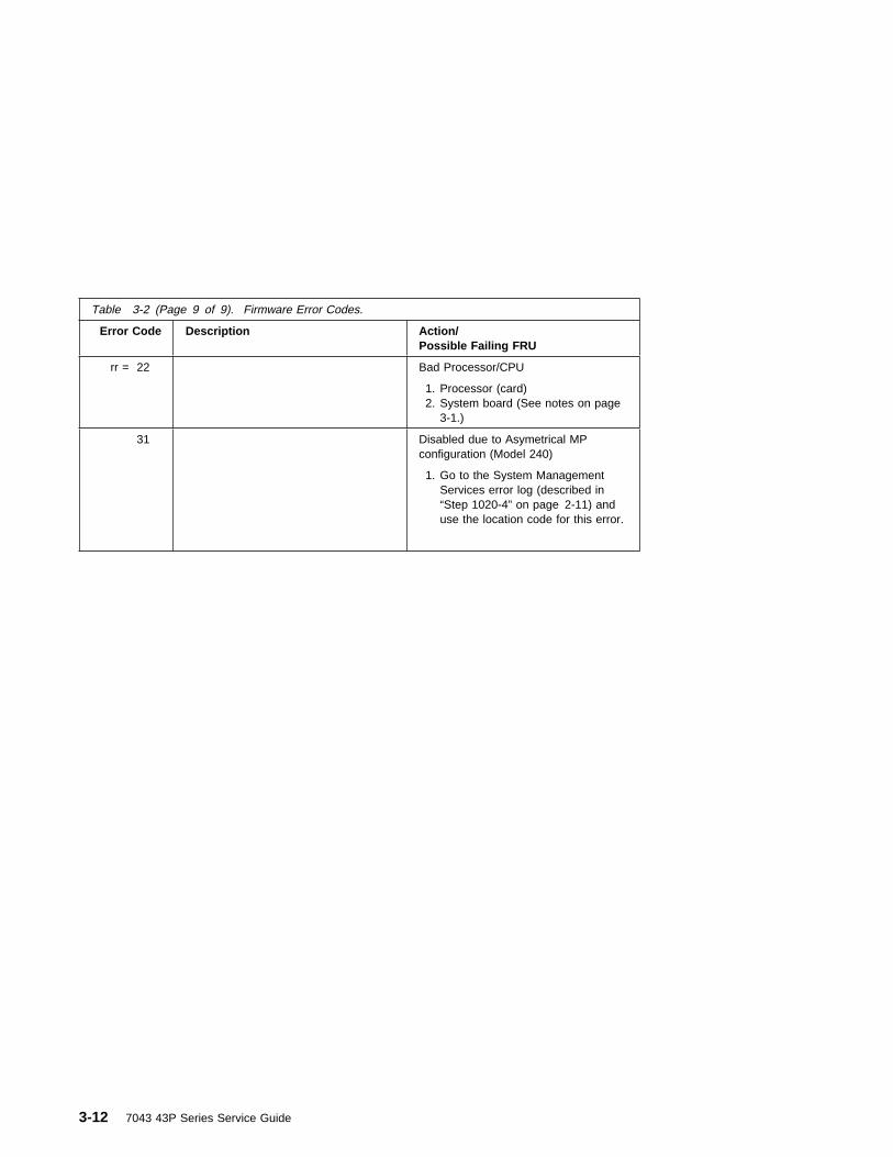
Table 3-2 (Page 9 of 9). Firmware Error Codes.
Error Code Description Action/Possible Failing FRU
rr = 22 Bad Processor/CPU
1. Processor (card)2. System board (See notes on page
3-1.)
31 Disabled due to Asymetrical MPconfiguration (Model 240)
1. Go to the System ManagementServices error log (described in“Step 1020-4” on page 2-11) anduse the location code for this error.
3-12 7043 43P Series Service Guide

Memory PD Bits
The following table expands the firmware error code 25Cyyxxx on page 3-10, whereyy is the PD values in the table below. Use these values to identify the type ofmemory that generated the error.
If you replace FRUs and the problem is still not corrected, go to MAP 0030 in theDiagnostics Information for Multiple Bus Systems unless otherwise indicated in thetables.
Table 3-3. Memory DIMM PD bits
PDvalue
Size
Speed(nsecs)
Parity/ECC
Single/Dual
64 8MB 60 ECC Single
69 16MB 60 ECC Single
6B 32MB 60 ECC Single
6D 64MB 60 ECC Single
6F 128MB 60 ECC Single
Chapter 3. Error Code to FRU Index for Model 140 and Model 240 3-13

Firmware Checkpoints
The following Fxx code checkpoints are displayed on the operator panel duringsystem startup, and can be used for diagnostic purposes.
If you replace FRUs and the problem is still not corrected, go to MAP 0030 in theDiagnostics Information for Multiple Bus Systems unless otherwise indicated in thetables.
Table 3-4 (Page 1 of 5). Firmware Checkpoints.
Checkpoint Description Action/Possible Failing FRU
F01 Performing system memory test
(May take several minutes if largeamount of memory installed.)
1. Memory modules.
2. System board
F05 Transfer control to OperatingSystem (normal boot).
See “Fxx Code Boot Problems” onpage 3-18.
F22 No memory detected (systemlockup) Note: The disk drive light ison continuously.
1. Memory modules 2. System board. (See 3-1.)
F2C Processor card mismatch (Model240)
If more than one processor card isinstalled in the Model 240, bothprocessor cards must be of thesame speed and type.
F4D Loading boot image See “Fxx Code Boot Problems” onpage 3-18.
F4F NVRAM initialization Go to “MAP 1540: MinimumConfiguration” on page 2-21.
F51 Probing primary PCI bus 1. PCI Adapters 2. Riser card 3. System board.
If a network adapter or systemboard is replaced, see 3-1.
F52 Probing for adapter FCODE,evaluate if present
1. PCI Adapters 2. Riser card 3. System board.
If a network adapter or systemboard is replaced, see 3-1.
3-14 7043 43P Series Service Guide

Table 3-4 (Page 2 of 5). Firmware Checkpoints.
Checkpoint Description Action/Possible Failing FRU
F55 Probing PCI bridge secondary bus 1. PCI Adapters 2. Riser card 3. System board.
If a network adapter or systemboard is replaced, see 3-1.
F5B Transferring control to OperatingSystem (service mode boot)
See “Fxx Code Boot Problems” onpage 3-18.
F5F Probing for adapter FCODE,evaluate if present
1. PCI Adapters 2. Riser card 3. System board.
If a network adapter or systemboard is replaced, see 3-1.
F74 Establishing host connection Refer to “Fxx Code Boot Problems”on page 3-18 for generalconsiderations.
1. Turn off then on, and retry theboot operation.
2. Verify the network connection(network could be down).
3. Verify that IP paramters arecorrect.
4. Try to “Ping” the target server.5. Have network administrator
verify the server configurationfor this client.
6. Check the network cable7. Check the network adapter. If
trying to boot using integratedethernet controller, replacesystem board. (See 3-1.)
Chapter 3. Error Code to FRU Index for Model 140 and Model 240 3-15

Table 3-4 (Page 3 of 5). Firmware Checkpoints.
Checkpoint Description Action/Possible Failing FRU
F75 BootP request Refer to “Fxx Code Boot Problems”on page 3-18 for generalconsiderations.
1. Turn off then on, and retry theboot operation.
2. Verify the network connection(network could be down).
3. Verify that IP paramters arecorrect.
4. Have network administratorverify the server configurationfor this client.
F9E Real time clock (RTC) initialization Refer to error code 28030xxx in“Firmware Error Codes” onpage 3-4.
FDC Dynamic console selection. Refer to “Fxx Code ConsoleProblems” on page 3-20.
FDD Processor exception 1. System board (See notes onpage 3-1.)
2. For Model 240, processorcards.
FDE Alternating pattern of FDE and FADindicates a processor exception hasbeen detected.
1. System board (See notes onpage 3-1.)
2. For Model 240, processorcards.
3-16 7043 43P Series Service Guide

Table 3-4 (Page 4 of 5). Firmware Checkpoints.
Checkpoint Description Action/Possible Failing FRU
FEA Firmware flash corrupted, load fromdiskette.
Ensure that the diskette installedcontains recovery image appropriatefor this system unit.
The System Management Servicesrecovery procedure for the flashEEPROM should be executed. See“Firmware Update” on page 7-24.
If the diskette is installed with thecorrect recovery image, thensuspect
1. Diskette 2. Diskette drive 3. Diskette cable
4. System board (See notes onpage 3-1.)
FEB Firmware flash corrupted, load fromdiskette.
Ensure that the diskette installedcontains recovery image appropriatefor this system unit.
The System Management Servicesrecovery procedure for the flashEEPROM should be executed. See“Firmware Update” on page 7-24.
If the diskette is installed with thecorrect recovery image, thensuspect
1. Diskette 2. Diskette drive 3. Diskette cable
4. System board (See notes onpage 3-1.)
FF2 Power-On Password prompt. If a console is attached but nothingis displayed on it, go to the “EntryMAP” on page 2-1 with thesymptom "All display problems."
FF3 Privileged-Access Password prompt If a console is attached but nothingis displayed on it, go to the “EntryMAP” on page 2-1 with thesymptom "All display problems."
Chapter 3. Error Code to FRU Index for Model 140 and Model 240 3-17

Fxx Code Boot Problems
Depending on the boot device, a checkpoint may be displayed on the operator panelfor an extended period of time while the boot image is retrieved from the device.This is particularly true for Tape and Network boot attempts. If the checkpoint/code isdisplayed for an extended time there may be a problem loading the boot image fromthe device. If booting from CDROM or Tape, watch for “activity” on the drive's LEDindicator. A blinking LED means that the loading of either the boot image oradditional information required by the operating system being booted is still inprogress.
For network boot attempts, if the system is not connected to an active network or ifthe target server is inaccessible (this can also result from incorrect IP parametersbeing supplied), the system still attempts to boot and because time-out durations arenecessarily long to accommodate retries, the system may appear to be hung.
1. Restart the system and get to the Firmware SMS utilities. In the utilities check:.� Is the intended boot device correctly specified in the boot sequence?
Table 3-4 (Page 5 of 5). Firmware Checkpoints.
Checkpoint Description Action/Possible Failing FRU
FFB SCSI bus initialization 1. Verify proper SCSI bustermination.
2. Verify that there are no IDconflicts among SCSI devices.
3. Verifiy that the system boardSCSI security jumpers are setproperly, if external devices areattached to the system boardSCSI bus.
4. Suspect the SCSI cable.
5. Suspect the drives.
6. Suspect the system board.
FFD The operator panel alternatesbetween the code FFD and anotherFxx code, where Fxx is the point atwhich the error occurred.
If the Fxx is not listed in this table,go to “MAP 1540: MinimumConfiguration” on page 2-21.
Not listed here Go to “MAP 1540: MinimumConfiguration” on page 2-21.
3-18 7043 43P Series Service Guide

� For network boot attempts:– Are the IP parameters correct?– Attempt to “Ping” the target server using the SMS “Ping” utility.
2. If the checkpoint F05 or F5B is displayed for an extended time, there may be aproblem with the integrity of the boot image.� Try to boot and run standalone diagnostics against the system, particularly
against the intended boot device. If the diagnostics are successful, it may benecessary to perform an operating system specific recovery process, orreinstall the operating system.
3. If attempting to boot from a Harddisk, CDROM, or Tape drive:a. Try a different CD/Tape (unless booting from Harddisk)b. Verify proper SCSI bus terminationc. Replace SCSI cabled. It is possible that another attached SCSI device is causing the problem.
Disconnect any other SCSI devices attached to the same controller as theone the boot device is attached to and retry the boot operation. If this issuccessful, one of the devices removed is causing the problem, re-attachdevices one by one and retry the boot operation until the problem recurs andreplace the device that caused the problem.
e. Replace SCSI adapter (if drive is attached to a card rather than the systemboard)
f. Replace SCSI driveg. It is possible that another installed adapter is causing the problem.
Remove all installed adapters except the one the boot device is attached to,try to boot the standalone diagnostics from a CDROM drive attached to thescsi controller on the system board, and run the diagnostics against thesystem.
If this is successful, re-install adapters (and attached devices as applicable)that were removed, one at a time, and run the standalone diagnosticsagainst the system.
h. Replace riser cardi. Replace system board
4. If attempting to boot from a Network controller:a. Power Off then On and retry the boot operationb. Verify the network connection (network could be down)c. Verify that IP parameters are correctd. Try to “Ping” the target servere. Have network administrator verify the server configuration for this clientf. Replace network cable
g. Replace network adapter (unless trying to boot using the ethernet controlleron the system board)
h. It is possible that another installed adapter is causing the problem.
Chapter 3. Error Code to FRU Index for Model 140 and Model 240 3-19

Remove all installed adapters except the one you are trying to boot, and tryto boot the standalone diagnostics from a CDROM drive attached to the scsicontroller on the system board. If this is successful, run the diagnosticsagainst the system, particularly against the target network bootcontroller/adapter.
If this is successful, re-install adapters (and attached devices as applicable)that were removed, one at a time, and run the diagnostics against thesystem.
i. Replace riser cardj. Replace system board (if not replaced in previous step)
5. If you replaced the indicated FRUs and the problem is still not corrected, or theabove descriptions did not address your particular situation, go to "MAP 1540:Minimum Configuration".
Fxx Code Console Problems: This section describes console problemsindicated by a code in the table under “Firmware Checkpoints” on page 3-14.
If a console is attached but nothing is displayed on it, follow the steps associatedwith “All display problems” in the “Entry MAP” on page 2-1. If the console selectionscreens can be seen on the terminals but there is no response to attempts to selectthe console:
1. If selecting the console with a keyboard attached to the system, replace thekeyboard. If replacing the keyboard does not fix the problem, replace the systemboard.
2. If selecting the console with an ASCII terminal, suspect the ASCII terminal. Usethe Problem Determination Procedures for the terminal. Replace the systemboard if these procedures do not reveal a problem.
Note: Terminal settings should be set to:� 9600 bps (bits per second)
� No Parity� 8 Data bits� 1 Stop bit
If you replace FRUs and the problem is still not corrected, go to MAP 0030 in theDiagnostics Information for Multiple Bus Systems unless otherwise indicated in thetables.
3-20 7043 43P Series Service Guide
Firmware Location Codes
These codes can be found in the System Management Services error log asdescribed in “Step 1020-4” on page 2-11.
Location codes vary in length depending on the device being referenced. In general,if a location code is referring to an adapter or controller, the location code is 4 digits(eg. 04-01 identifies the device/controller/adapter on the PCI bus, in physical slot 1).If a device is optional and plugs into an adapter/controller, it is normally 8 digits (eg.01-C0-00-00 is identifying the first diskette drive).
Location Code format
The basic format of the location code is:
� For non-SCSI devices/drives AB-CD-EF-GH� For SCSI devices/drives (not controllers/adapters)
AB-CD-EF-G,H
“G” is the SCSI bus ID (PUN) of the device and “H” is the Logical UnitNumber (LUN).
The “AB” value identifies the bus type as follows:
The “CD” value depends on whether the device is integrated or a plug in adapter.For plug in adapters, the value is a decimal number in the range of 01 to 99 thatidentifies the system slot. For integrated devices (eg. the integrated PCI Ethernetcontroller), the value of “C” is an uppercase alphabetic character in the range from Ato Z and is generated based on the device “discovery” order as specified in the OpenFirmware 1275 specification for the “probe” process which translates into “DeviceTree” order. The “D” value is set to 0.
The “EF” value, as generated by the firmware, is always 00.
The “GH” value (except for SCSI devices) is a subsystem dependent “index” valueindicating subordinate devices of the parent identified by the “AB-CD-EF” value.
Examples:
00 Processor bus01 ISA bus04 PCI bus05 PCMCIA bus
Chapter 3. Error Code to FRU Index for Model 140 and Model 240 3-21

Note: The values used in the examples are representative of the format andrelationships described above.
00-00 System board00-00-00-01 Memory SIMM/DIMM in socket 101-A0 ISA bus Primary IDE controller01-C0 ISA bus Diskette Controller01-C0-00-01 2nd ISA bus Diskette drive00-00 2nd ISA bus Serial Port (SRN value differentiates between 1st and 2nd)04-01 PCI Adapter in system slot 104-01-00-13,0 SCSI device at SCSI bus ID 13 (decimal) attached to the PCI SCSI controller in
system slot 104-B0 2nd Integrated PCI device (eg. Ethernet controller)04-C0 3rd Integrated PCI device (eg. SCSI controller)04-C0-00-13,0 SCSI device at SCSI bus ID 13 (decimal) attached to the PCI SCSI controller
integrated on the system board.00-00 1st Processor on Model 240 (Proc 0)00-01 2nd Processor on Model 240 (Proc 1)
3-22 7043 43P Series Service Guide

Chapter 4. Error Code to FRU Index for the Model 150
Note: This chapter contains error code and checkpoint information for the Model150 only. For information on the Model 140 and Model 240, refer toChapter 3, “Error Code to FRU Index for the Model 140 and Model 240” onpage 3-1.
If you replace FRUs and the problem is still unresolved, go to “MAP 1540: MinimumConfiguration” on page 2-21, unless otherwise indicated in the tables. If you replaceFRUs and the problem has been resolved, go to "MAP 0410: Repair Checkout" inthe Diagnostics Information for Multiple Bus Systems, unless otherwise indicated inthe tables.
Error Codes
The error codes listed in Table 4-1, in most cases, identifies the failing device/FRU.Refer to Appendix A, “Interpreting Firmware Error Codes” on page A-1 forinformation on interpreting 8-digit error codes. A physical location code may bedisplayed with the error code. If so, use the physical location code to identify thesuspected FRU.
Table 4-1 (Page 1 of 11). Firmware Error Codes
Error Code Function /Description
Repair Action/Possible Failing FRU
Remote Initial program load (RIPL) errors
20A80000 Insufficientinformation to boot
Verify the IP address
20A80001 Client IP address isalready in use byanother networkdevice
Change IP address
20A80002 Cannot get gatewayIP address
Refer to Firmware Checkpoints using code E174
20A80003 Cannot get serverhardware address
Refer to Firmware Checkpoint using code E174
20A80004 Bootp failed Refer to Firmware Checkpoint using code E175
20A80005 File transmission(TFTP) failed
Check network connection, try again.
20A80006 Boot Image TooLarge
Contact your service representative for assistance.
Unknown/Unrecognized device
Chapter 4. Error Code to FRU Index for the Model 150 4-1

Table 4-1 (Page 2 of 11). Firmware Error Codes
Error Code Function /Description
Repair Action/Possible Failing FRU
20D0000F Selftest failed ondevice, noerror/location codeinformation available
Check the SMS error log entry for this error code. Thelocation code (if present) in the error log entry shouldidentify the location of the failing device.
20D00010 Selftest failed ondevice, can't locatepackage
Software Error (Contact your service representative forassistance.)
20D00011 Cannot determineMachine Model.
The Machine Model is part of the System Vital ProductData. Perform corrective actions listed for errors2BA00050, 2BA00051.
Security
20E00000 Power on Passwordentry error
The password has been entered incorrectly.
Retry installing the password.
20E00001 Privilege Passwordentry error
The password has been entered incorrectly.
Retry installing the password.
20E00002 Privilege PasswordJumper not enabled
The Privileged Password jumper is not in the correctposition for password initial entry.
Consult the system's User's Guide for pin location andjumper position.
20E00003 Power on Passwordmust be set forUnattended mode
Unattended mode requires the setting of the Power Onpassword before it is enabled.
20E00004 Battery drained orneeds replacement
1. Replace battery2. Replace System Planar
20E00005 EEPROM locked 1. Power Off/On machine2. Replace System Planar
20E00008 CMOS corrupted ortampering evident,CMOS initialized
Check your machine for evidence of tampering
If NO tampering:
1. Replace battery, restore NVRAM data (passwords,startup data)
2. Replace System Planar
20E00009 Invalid passwordentered - systemlocked
The password has been entered incorrectly 3 times.
Power Off/On the machine and enter the passwordcorrectly
20E0000A EEPROM lockproblem
If for PAP install, is jumper in correct position?
Consult the system's User's Guide for pin location andjumper position.
1. Power Off/On machine2. Replace System Planar
4-2 7043 43P Series Service Guide

Table 4-1 (Page 3 of 11). Firmware Error Codes
Error Code Function /Description
Repair Action/Possible Failing FRU
20E0000B EEPROM writeproblem
1. Power Off/On machine2. Replace System Planar
20E0000C EEPROM readproblem
1. Power Off/On machine2. Replace System Planar
20E00017 Cold boot neededfor password entry
Power Off/On machine
Informational
20EE0003 IP parameterrequires 3 dots "."
Enter valid IP parameter
Example: 000.000.000.000
20EE0004 Invalid IP parameter Enter valid (numeric) IP parameter
Example: 000.000.000.000
20EE0005 Invalid IP parameter(>255)
Enter valid (numeric) IP parameter in the range of 0 to255
Example: 255.199.002.000
20EE0006 No SCSI controllerspresent
The System Planar should always have (at least) the2 integrated PCI SCSI controllers
1. Replace System Planar
20EE0007 Keyboard not found 1. Plug in keyboard2. Replace System Planar
20EE0008 No configurableadapters found inthe system
This warning occurs when the selected SMS functioncannot locate any devices/adapters supported by thefunction. If a supported device is installed:
1. Replace the device or adapter2. Replace System Planar
Chapter 4. Error Code to FRU Index for the Model 150 4-3

Table 4-1 (Page 4 of 11). Firmware Error Codes
Error Code Function /Description
Repair Action/Possible Failing FRU
20EE000A Pointer to OperatingSystem not found innon-volatile storage
Values normally found in non-volatile storage that pointto the location of an Operating System were not found.This can happen for two reasons, either your installedOperating System doesn't support storing the values orsome event occurred that caused the system to losenon-volatile storage information (drainage orreplacement of the battery). If you are running AIX,this information can be reconstructed by running thebootlist command specifying the device that theOperating System is installed on. Please refer to yourAIX documentation for the exact syntax and usage ofthe bootlist command.
In order to boot the Operating System so that theabove mentioned values can be reconstructed, powerthe system down and power it back up again, thisshould cause the system to look for the OperatingSystem in the devices contained in the custom boot listor in the default boot list, depending on the condition ofthe system. If this is not successful, modify the BootSequence (also known as boot list) to include devicesthat are known to contain a copy of the OperatingSystem. This can be accomplished by using theSystem Management Services Menus. For example,select a hard disk known to have a copy of theOperating System as the first and only device in theboot sequence (boot list) and attempt to boot again.
20EE000B The system was notable to find anOperating Systemon the device listthat was attempted.
Modify the Boot Sequence (also known as boot list) toinclude devices that are known to contain a copy of theOperating System. This can be accomplished bypowering down the system, powering it back up again,and using the System Management Services Menus.For example, select a hard disk known to have a copyof the Operating System as the first and only device inthe boot sequence (boot list) and attempt to bootagain.
SCSI Device errors
SCSI device error notes:
1. Before replacing any system components
a. Ensure that the controller and each device on the SCSI bus is assigned a unique SCSI ID.b. Ensure SCSI bus is properly terminated.c. Ensure SCSI signal and power cables are securely connected and not damaged.
2. The location code information is required to identify the ID of SCSI device failures as well as toindicate the location of the controller to which the device is attached.
4-4 7043 43P Series Service Guide

Table 4-1 (Page 5 of 11). Firmware Error Codes
Error Code Function /Description
Repair Action/Possible Failing FRU
21A00001 Test Unit ReadyFailed - hardwareerror
Refer to SCSI device error notes above
1. Replace SCSI device2. Replace SCSI cable3. Replace SCSI controller
21A00002 Test Unit ReadyFailed - sense dataavailable
Refer to SCSI device error notes above
1. Replace Media (Removable media devices)2. Replace SCSI device
21A00003 Send DiagnosticFailed
Refer to SCSI device error notes above
1. Replace SCSI device
21A00004 Send DiagnosticFailed - DevOfl cmd
Refer to SCSI device error notes above
1. Replace SCSI device
21E00xxx SCSI Tape Refer to 21A00xxx error codes for a description andrepair action for the specific “xxx” value.
21ED0xxx SCSI Changer Refer to 21A00xxx error codes for a description andrepair action for the specific “xxx” value.
21EE0xxx Other SCSI devicetype
Refer to 21A00xxx error codes for a description andrepair action for the specific “xxx” value.
21F00xxx SCSI CDROM Refer to 21A00xxx error codes for a description andrepair action for the specific “xxx” value.
21F20xxx SCSI Read/WriteOptical
Refer to 21A00xxx error codes for a description andrepair action for the specific “xxx” value.
Network Controller problem
22000001 Internal wrap testfailed.
Replace the card.
22001001 Internal wrap testfailed.
Replace the card.
22010001 Adapter failed tocomplete hardwareinitilization.
Replace the card.
22011001 Adapter failed tocomplete hardwareinitilization.
Replace the card.
22020001 Adapter failed tocomplete hardwareinitilization.
Replace the card.
Memory Controller problem
25000000 Memory controllerfailed
Replace System Planar
Flash Update problem
Chapter 4. Error Code to FRU Index for the Model 150 4-5

Table 4-1 (Page 6 of 11). Firmware Error Codes
Error Code Function /Description
Repair Action/Possible Failing FRU
25010000 No diskette in drive Insert diskette containing firmware update file
25010001 Diskette seek error 1. Retry function.2. Replace diskette drive3. Replace diskette cable4. Replace System Planar
25010002 Diskette in drivedoes not contain an*.IMG file
Insert diskette with firmware update file
25010003 Cannot openOPENPROMpackage
1. Replace System Planar
25010004 Cannot findOPENPROM node
1. Replace System Planar
25010006 System id does notmatch image systemid
Make sure correct firmware update diskette is beingused with this system.
25010007 Image has bad CRC 1. Replace firmware updated diskette
25010008 Flash is writeprotected, updatecancelled
1. Power Off/On machine and retry2. Replace System Planar
25010009 Flash module isunsupported or notrecognized
Make sure correct firmware update diskette is beingused with this system.
2501000A Flash writeprotected.
1. Power Off/On machine and retry2. Replace System Planar
NVRAM problems
NVRAM problem resolution:
1. Errors reported against NVRAM can be caused by low Battery voltage and (more rarely) poweroutages that occur during normal system usage. With the exception of the 25A80000 error, theseerrors are really just warnings that the NVRAM data content had to be re-established and do notrequire any FRU replacement unless the error is persistent. When one of these errors occurs,any system customization (eg. boot device list) information has been lost, the system may needto be re-configured.
2. If the error is persistent, replace the battery.
3. If the error is persistent after battery replacement, or the error code is 25A80000, replace theSystem Planar.
25A80000 Initialization failed,device test failed
Refer to NVRAM problem resolution above
25A80001 init-nvram invoked,ALL of NVRAMinitialized
Refer to NVRAM problem resolution above
4-6 7043 43P Series Service Guide

Table 4-1 (Page 7 of 11). Firmware Error Codes
Error Code Function /Description
Repair Action/Possible Failing FRU
25A80002 init-nvram invoked,some data partitionsmay have beenpreserved
Refer to NVRAM problem resolution above
25A80011 Data corruptiondetected, ALL ofNVRAM initialized
Refer to NVRAM problem resolution above
25A80012 Data corruptiondetected, some datapartitions may havebeen preserved
Refer to NVRAM problem resolution above
25A80100 NVRAM datavalidation checkfailed
Power Off/On machine and retry the operation beforereplacing any system components.
Refer to NVRAM problem resolution above
25A80201 Unable to expandtarget partition whilesaving configurationvariable
Refer to NVRAM problem resolution above
25A80202 Unable to expandtarget partition whilewriting error logentry
Refer to NVRAM problem resolution above
25A80203 Unable to expandtarget partition whilewriting VPD data
Refer to NVRAM problem resolution above
25A80210 Setenv/$Setenvparameter error -name contains a nullcharacter
Refer to NVRAM problem resolution above
25A80211 Setenv/$Setenvparameter error -value contains a nullcharacter
Refer to NVRAM problem resolution above
Chapter 4. Error Code to FRU Index for the Model 150 4-7

Table 4-1 (Page 8 of 11). Firmware Error Codes
Error Code Function /Description
Repair Action/Possible Failing FRU
25A80998 NVRAMRC scriptevaluation error -command lineexecution error
Execution of a command line within the nvramconfiguration variable “nvramrc” (script) resulted in a“throw” being executed. This script can be modified bythe system firmware SMS utilities, the operatingsystem, PCI adapter rom code or utility, or an operator(via the open firmware script editing command“nvedit”). It may not be possible to resolve theproblem without a detailed analysis of the nvram script,the current system configuration, and device treecontents.
1. The problem can be caused by a SCSIadapter,whose SCSI bus ID has been changedfrom the default setting, no longer appearing in thesystem. This can be caused either by removing aSCSI adapter, or a problem with a SCSI adapter.
a. Select the “SCSI ID” utility from the SMSmenu(s).
1) Verify the list of SCSI controllers/adapters.If the list is not correct, suspect a problemwith the adapter(s) installed but not listed.
2) Select the option to “Save” theconfiguration information.
3) Restart the system.b. If the problem persists, boot the operating
system and verify the SCSI bus IDs of anyinstalled/available SCSI controllers (change asnecessary), and restart the system.
2. Contact your service support representative forfurther assistance.
EEPROM problems
EEPROM problem resolution:
1. Ensure that the EEPROM Security jumper is in the correct position if doing a PAP install.
2. Retry the operation.
3. If retries do not solve the problem, replace the System Planar.
25AA0000 Unable to unlockeeprom
Refer to EEPROM problem resolution above
25AA0001 Read-Recv error Refer to EEPROM problem resolution above
25AA0002 Read-Trans error Refer to EEPROM problem resolution above
25AA0003 Write-enable error Refer to EEPROM problem resolution above
25AA0004 Write-recv error Refer to EEPROM problem resolution above
25AA0005 Write-disable error Refer to EEPROM problem resolution above
25AA0006 Write-Trans error Refer to EEPROM problem resolution above
4-8 7043 43P Series Service Guide
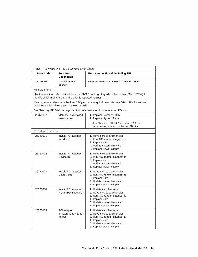
Table 4-1 (Page 9 of 11). Firmware Error Codes
Error Code Function /Description
Repair Action/Possible Failing FRU
25AA0007 Unable to lockeeprom
Refer to EEPROM problem resolution above
Memory errors
Use the location code obtained from the SMS Error Log utility (described in Map Step 1020-4) toidentify which memory DIMM the error is reported against.
Memory error codes are in the form 25Cyyrrr where yy indicates Memory DIMM PD-bits and rrrindicates the last three digits of the error code.
See “Memory PD Bits” on page 4-13 for information on how to interpret PD bits.
25Cyy002 Memory DIMM failedmemory test
1. Replace Memory DIMM2. Replace System Planar
See “Memory PD Bits” on page 4-13 forinformation on how to interpret PD bits.
PCI adapter problem
26020001 Invalid PCI adapterVendor ID
1. Move card to another slot2. Run AIX adapter diagnostics
3. Replace card4. Update system firmware5. Replace power supply
26020002 Invalid PCI adapterDevice ID
1. Move card to another slot2. Run AIX adapter diagnostics
3. Replace card4. Update system firmware5. Replace power supply
26020003 Invalid PCI adapterClass Code
1. Move card to another slot2. Run AIX adapter diagnostics
3. Replace card4. Update system firmware5. Replace power supply
26020004 Invalid PCI adapterROM VPD Structure
1. Update card firmware2. Move card to another slot3. Run AIX adapter diagnostics
4. Replace card5. Update system firmware6. Replace power supply
26020005 PCI adapterfirmware is too largeto load
1. Update card firmware2. Move card to another slot3. Run AIX adapter diagnostics
4. Replace card5. Update system firmware6. Replace power supply
Chapter 4. Error Code to FRU Index for the Model 150 4-9

Table 4-1 (Page 10 of 11). Firmware Error Codes
Error Code Function /Description
Repair Action/Possible Failing FRU
26020006 PCI adapterfirmware failedevaluation (has abug)
1. Update card firmware2. Move card to another slot3. Run AIX adapter diagnostics
4. Replace card5. Update system firmware6. Replace power supply
26020007 Unable to allocateBus resources toPCI adapter (partialallocation may havesucceeded)
1. Move card to another slot (bridge)2. Update card firmware3. Run AIX adapter diagnostics
4. Replace card5. Update system firmware6. Replace power supply
RTC errors
RTC problem resolution:
1. Errors reported against the Real Time Clock can be caused by low Battery voltage and (morerarely) power outages that occur during normal system usage. Most of these errors are really justwarnings that the Real Time Clock data content needs to be re-established and do not requireany FRU replacement unless the error is persistent. When one of these errors occurs, the PowerOn Password and Time and Date information has probably been lost.
� To set/restore a Power On Password, use the S.M.S. utility.� To set/restore the Time and Date, use the Operating System facility.
2. If the error is persistent, replace the battery on the System Planar.
3. If the error is persistent after battery replacement, replace the System Planar.
28030001 RTC initializationrequired - RTC notupdating, corrected
1. Set/Restore the Time and Date2. Refer to RTC problem resolution above if problem
persists.
28030002 Bad time/datevalues
1. Set the Time and Date2. Refer to RTC problem resolution above if problem
persists.
28030003 RTC initializationrequired - RTC notupdating, notcorrected
1. Replace the System Planar.
28030004 RTC operatingmode parameterschanged (ie. dataformat)
1. Set/Restore the Time and Date2. Refer to RTC problem resolution above if problem
persists.
28030005 RTC Battery error 1. Replace the battery
Note: Password, Time, and Date needs to be set2. Refer to RTC problem resolution above if problem
persists.
Keyboard/Mouse problems
4-10 7043 43P Series Service Guide

Table 4-1 (Page 11 of 11). Firmware Error Codes
Error Code Function /Description
Repair Action/Possible Failing FRU
29000002 Keyboard/Mousecontroller failedselftest
1. Replace System Planar
29A00003 Keyboard notpresent/detected
1. Keyboard2. Replace System Planar
29A00004 Keyboard stuck keydetected
1. Keyboard2. Replace the System Planar.
29B00004 Mouse notpresent/detected
1. Mouse2. Replace System Planar
Bus SRN to FRU Reference Table
This table is used to locate defective FRUs within the I/O board PCI and ISA buses.The table indicates which devices should be tested for each SRN. For thisprocedure, if possible, diagnostics are run on the I/O board bus devices with alladapters removed from the failing bus. If a failure is detected on this system with alladapters removed from the failing bus, the I/O board is the isolated FRU. If a failureis not detected, the adapters are added back one at a time, to their original slotlocation, and the configuration is tested until a failure is detected. The failure is thenisolated to the failing FRU.
If a failure has not been detected and all the FRUs have been tested call yourtechnical service support person for assistance.
Table 4-2 (Page 1 of 2). Bus SRN to FRU Reference Table
SRN BusIdentification
Possible Failing Device and AIXLocation Code
AssociatedFRU
9CC-100 PCI Bus 00 Internal SCSI port 1 (10-60) I/O board. (Seenote at thebottom of thistable.)
Internal/External SCSI port 2 (30-58) I/O board. (Seenote at thebottom of thistable.)
Internal Ethernet port (10-80) I/O board. (Seenote at thebottom of thistable.)
Device installed in I/O Slot 3P (10-68to 10-6F)
Adapter
Chapter 4. Error Code to FRU Index for the Model 150 4-11
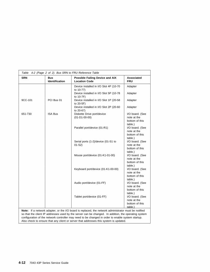
Table 4-2 (Page 2 of 2). Bus SRN to FRU Reference Table
SRN BusIdentification
Possible Failing Device and AIXLocation Code
AssociatedFRU
Device installed in I/O Slot 4P (10-70to 10-77)
Adapter
Device installed in I/O Slot 5P (10-78to 10-7F)
Adapter
9CC-101 PCI Bus 01 Device installed in I/O Slot 1P (20-58to 20-5F)
Adapter
Device installed in I/O Slot 2P (20-60to 20-67)
Adapter
651-730 ISA Bus Diskette Drive port/device(01-D1-00-00)
I/O board. (Seenote at thebottom of thistable.)
Parallel port/device (01-R1) I/O board. (Seenote at thebottom of thistable.)
Serial ports (1-2)/device (01-S1 to01-S2)
I/O board. (Seenote at thebottom of thistable.)
Mouse port/device (01-K1-01-00) I/O board. (Seenote at thebottom of thistable.)
Keyboard port/device (01-K1-00-00) I/O board. (Seenote at thebottom of thistable.)
Audio port/device (01-FF) I/O board. (Seenote at thebottom of thistable.)
Tablet port/device (01-FF) I/O board. (Seenote at thebottom of thistable.)
Note: If a network adapter, or the I/O board is replaced, the network administrator must be notifiedso that the client IP addresses used by the server can be changed. In addition, the operating systemconfiguration of the network controller may need to be changed in order to enable system startup.Also check to ensure that any client or server that addresses this system is updated.
4-12 7043 43P Series Service Guide

Memory PD BitsThe following table expands the firmware error code 25Cyyrrr on 4-9, where yy isthe PD values in the table below. Use these values to identify the type of memorythat generated the error.
If you replace FRUs and the problem is still not corrected, go to MAP 0030 in theDiagnostics Information for Multiple Bus Systems unless otherwise indicated in thetables.
Firmware Checkpoints
The following is a list of checkpoints issued by the firmware during initialization.
PD Value Size Speed (nsecs) Parity/ECC
38 128MB 10 ECC
3A 128MB 8 ECC
48 64MB 10 ECC
4A 64MB 8 ECC
68 256MB 10 ECC
6A 256MB 8 ECC
Table 4-3 (Page 1 of 13). Firmware Checkpoints
Checkpoint(hex)
Description Repair Action
E100 Reserved/Unused See “Unresolved problems” on page 4-26
E101 Video enabled,extended memorytest (Quick restartpath)
See “Unresolved problems” on page 4-26
E102 Firmware restartwith cfg'd parms(Quick restart path)
See “Unresolved problems” on page 4-26
E103 Set memory refresh(composite img)
See “Unresolved problems” on page 4-26
E104 Set memory refresh(recovery block)
See “Unresolved problems” on page 4-26
E105 Transfer control toO.S. (normal boot)
See “Boot Problems/Concerns” on page 4-27
E108 Run recovery blockbase memory (test2k), set stack
See “Unresolved problems” on page 4-26
Chapter 4. Error Code to FRU Index for the Model 150 4-13

Table 4-3 (Page 2 of 13). Firmware Checkpoints
Checkpoint(hex)
Description Repair Action
E109 Copy CRCverification code toRAM
See “Unresolved problems” on page 4-26
E10A Turn on cache See “Unresolved problems” on page 4-26
E10B Flush cache See “Unresolved problems” on page 4-26
E10C Jump to CRCverification code inRAM
See “Unresolved problems” on page 4-26
E10D Compute compositeimage CRC
See “Unresolved problems” on page 4-26
E10E Jump back to ROM See “Unresolved problems” on page 4-26
E10F Transfer control toOpen Firmware
See “Unresolved problems” on page 4-26
E110 Turn off cache,Check if compositeimage CRC is valid
See “Unresolved problems” on page 4-26
E111 GOOD CRC - jumpto composite image
See “Unresolved problems” on page 4-26
E112 BAD CRC - initializebase memory, stack
See “Unresolved problems” on page 4-26
E113 BAD CRC - copyuncompressedrecovery block codeto RAM
See “Unresolved problems” on page 4-26
E114 BAD CRC - jump tocode in RAM
See “Unresolved problems” on page 4-26
E115 BAD CRC - turn oncache
See “Unresolved problems” on page 4-26
E116 BAD CRC - copyrecovery block datasection to RAM
See “Unresolved problems” on page 4-26
E117 BAD CRC -Invalidate and flushcache, set TOC
See “Unresolved problems” on page 4-26
E118 BAD CRC - branchto high levelrecovery controlroutine
See “Unresolved problems” on page 4-26
4-14 7043 43P Series Service Guide
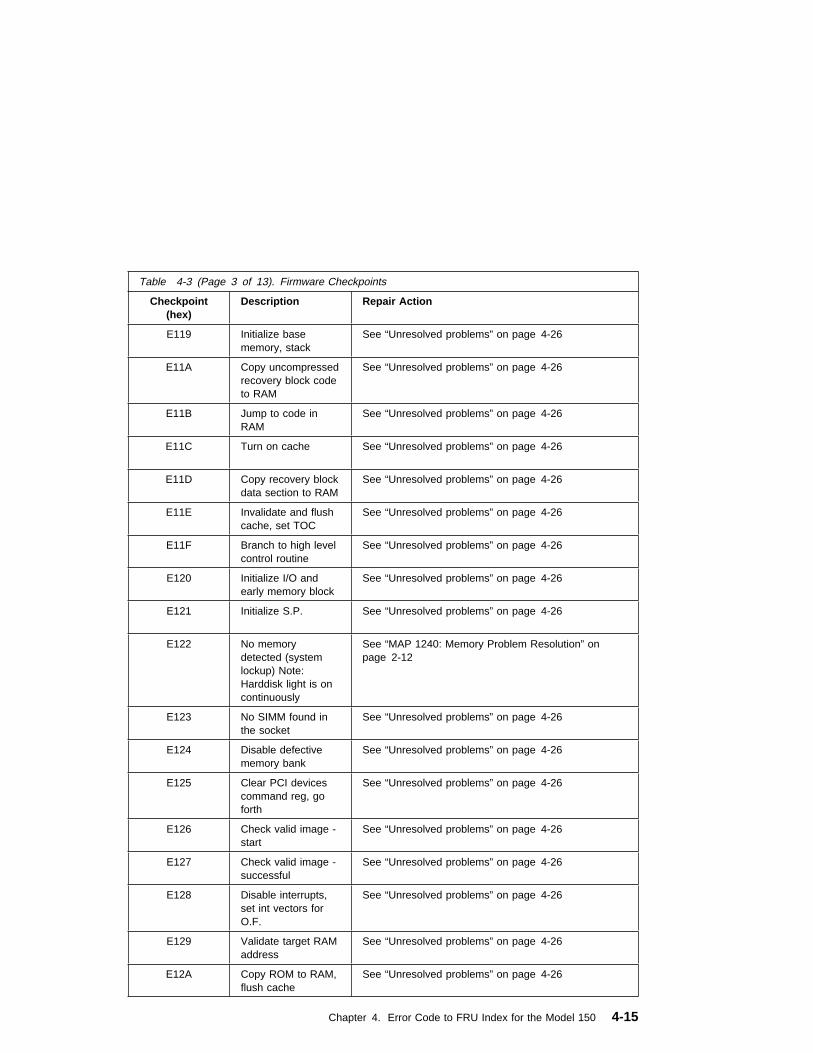
Table 4-3 (Page 3 of 13). Firmware Checkpoints
Checkpoint(hex)
Description Repair Action
E119 Initialize basememory, stack
See “Unresolved problems” on page 4-26
E11A Copy uncompressedrecovery block codeto RAM
See “Unresolved problems” on page 4-26
E11B Jump to code inRAM
See “Unresolved problems” on page 4-26
E11C Turn on cache See “Unresolved problems” on page 4-26
E11D Copy recovery blockdata section to RAM
See “Unresolved problems” on page 4-26
E11E Invalidate and flushcache, set TOC
See “Unresolved problems” on page 4-26
E11F Branch to high levelcontrol routine
See “Unresolved problems” on page 4-26
E120 Initialize I/O andearly memory block
See “Unresolved problems” on page 4-26
E121 Initialize S.P. See “Unresolved problems” on page 4-26
E122 No memorydetected (systemlockup) Note:Harddisk light is oncontinuously
See “MAP 1240: Memory Problem Resolution” onpage 2-12
E123 No SIMM found inthe socket
See “Unresolved problems” on page 4-26
E124 Disable defectivememory bank
See “Unresolved problems” on page 4-26
E125 Clear PCI devicescommand reg, goforth
See “Unresolved problems” on page 4-26
E126 Check valid image -start
See “Unresolved problems” on page 4-26
E127 Check valid image -successful
See “Unresolved problems” on page 4-26
E128 Disable interrupts,set int vectors forO.F.
See “Unresolved problems” on page 4-26
E129 Validate target RAMaddress
See “Unresolved problems” on page 4-26
E12A Copy ROM to RAM,flush cache
See “Unresolved problems” on page 4-26
Chapter 4. Error Code to FRU Index for the Model 150 4-15

Table 4-3 (Page 4 of 13). Firmware Checkpoints
Checkpoint(hex)
Description Repair Action
E12B Set MP operationalparameters (eg.L.E.?, Real?)
See “Unresolved problems” on page 4-26
E12C Set MP CPU nodecharacteristics
See “Unresolved problems” on page 4-26
E12D Park secondaryprocessors inparking lot
See “Unresolved problems” on page 4-26
E12E Primary processorsync
See “Unresolved problems” on page 4-26
E12F Unexpected returnfrom Open Firmware(system lockup)
See “Unresolved problems” on page 4-26
E130 Build device tree See “Unresolved problems” on page 4-26
E131 Create ROOT node See “Unresolved problems” on page 4-26
E132 Create CPUs node See “Unresolved problems” on page 4-26
E133 Create L2 Cachenode
See “Unresolved problems” on page 4-26
E134 Create memorynode
See “Unresolved problems” on page 4-26
E135 Create memorySIMM/DIMM node
See “Unresolved problems” on page 4-26
E136 Test memory See “Unresolved problems” on page 4-26
E137 Create openpromnode
See “Unresolved problems” on page 4-26
E138 Create options node See “Unresolved problems” on page 4-26
E139 Create aliases nodeand system aliases
See “Unresolved problems” on page 4-26
E13A Create packagesnode
See “Unresolved problems” on page 4-26
E140 PReP style load See “Unresolved problems” on page 4-26
E149 Create boot mgrnode
See “Unresolved problems” on page 4-26
4-16 7043 43P Series Service Guide

Table 4-3 (Page 5 of 13). Firmware Checkpoints
Checkpoint(hex)
Description Repair Action
E14C Createterminal-emulatornode
See “Unresolved problems” on page 4-26
E14D Load boot image See “Boot Problems/Concerns” on page 4-27
E14E Create ClientInterfacenode/dictionary
See “Unresolved problems” on page 4-26
E14F NVRAM validation,config variable tokengeneration
See “Unresolved problems” on page 4-26
E150 Create host(primary) PCIcontroller node
See “Unresolved problems” on page 4-26
E151 Probe primary PCIbus
1. Replace PCI Adapter(s)2. Replace System Planar
See “Unresolved problems” on page 4-26
E152 Probe for adapterFCODE, evaluate ifpresent
1. Replace PCI Adapter(s)2. Replace System Planar
See “Unresolved problems” on page 4-26
E153 End adapter FCODEprobe/evaluation
See “Unresolved problems” on page 4-26
E154 Create PCI bridgenode
See “Unresolved problems” on page 4-26
E155 Probe PCI bridgesecondary bus
1. Replace PCI Adapter(s)2. Replace System Planar
See “Unresolved problems” on page 4-26
E156 Create PCI ethernetnode
See “Unresolved problems” on page 4-26
E15A Create 64 bit host(primary) PCIcontroller node
See “Unresolved problems” on page 4-26
E15B Transfer control toO.S. (Service modeboot)
See “Boot Problems/Concerns” on page 4-27
E15C Probe primary 64 bitPCI bus
See “Unresolved problems” on page 4-26
E15D Create host PCIcontroller node
See “Unresolved problems” on page 4-26
E15E Create MPIC node See “Unresolved problems” on page 4-26
Chapter 4. Error Code to FRU Index for the Model 150 4-17

Table 4-3 (Page 6 of 13). Firmware Checkpoints
Checkpoint(hex)
Description Repair Action
E15F Adapter VPD probe See “Unresolved problems” on page 4-26
E160 CPU Node VPDCreation
See “Unresolved problems” on page 4-26
E161 ROOT Node VPDCreation
See “Unresolved problems” on page 4-26
E162 SP Node VPDCreation
See “Unresolved problems” on page 4-26
E164 Create PCI graphicsnode (P9)
See “Unresolved problems” on page 4-26
E168 Create PCI graphicsnode (S3)
See “Unresolved problems” on page 4-26
E16C GXT1000PSubsystem Openrequest
See “Unresolved problems” on page 4-26
E16D GXT1000P Planarnot detected/faileddiagnostics
See “Unresolved problems” on page 4-26
E16E GXT1000PSubsystem Opensuccessful
See “Unresolved problems” on page 4-26
E16F GXT1000P CloseSubsystem
See “Unresolved problems” on page 4-26
E170 Start of PCI BusProbe
See “Unresolved problems” on page 4-26
E171 Executing PCI-Delayfunction
See “Unresolved problems” on page 4-26
E174 Establish hostconnection
Refer to “Boot Problems/Concerns” on page 4-27 forsome general information concerning network booting.
E175 BootP request Refer to “Boot Problems/Concerns” on page 4-27 forsome general information concerning network booting.
1. Power Off then On and retry the boot operation2. Verify the network connection3. Have network administrator verify the server
configuration for this client
E176 TFTP file transfer See “Unresolved problems” on page 4-26
E177 Transfer failure dueto TFTP errorcondition
See “Unresolved problems” on page 4-26
E178 Create PCI tokenring node
See “Unresolved problems” on page 4-26
4-18 7043 43P Series Service Guide

Table 4-3 (Page 7 of 13). Firmware Checkpoints
Checkpoint(hex)
Description Repair Action
E180 SP Command setup See “Unresolved problems” on page 4-26
E183 SP Post See “Unresolved problems” on page 4-26
E190 Create ISA node See “Unresolved problems” on page 4-26
E193 Initialize Super I/O See “Unresolved problems” on page 4-26
E196 Probe ISA bus See “Unresolved problems” on page 4-26
E19B Create ServiceProcessor node
See “Unresolved problems” on page 4-26
E19C Create tablet node See “Unresolved problems” on page 4-26
E19D Create nvram node See “Unresolved problems” on page 4-26
E19E RTC node creationand initialization
Refer to Error Code 28030xxx
E19F Create eeprom node See “Unresolved problems” on page 4-26
E1AD See description ofcheckpoint E1DE.
See “Unresolved problems” on page 4-26
E1B0 Create lpt node Replace System Planar
See “Unresolved problems” on page 4-26
E1B1 Create serial node See “Unresolved problems” on page 4-26
E1B2 Create audio node Replace System Planar
See “Unresolved problems” on page 4-26
E1B3 Create 8042 node Replace System Planar
See “Unresolved problems” on page 4-26
E1B6 Probe for (ISA)keyboard
Replace System Planar
See “Unresolved problems” on page 4-26
E1BA Enable L2 cache See “Unresolved problems” on page 4-26
E1BB Set cache parms forburst
See “Unresolved problems” on page 4-26
E1BC Set cache parms for512KB
See “Unresolved problems” on page 4-26
Chapter 4. Error Code to FRU Index for the Model 150 4-19

Table 4-3 (Page 8 of 13). Firmware Checkpoints
Checkpoint(hex)
Description Repair Action
E1BD Probe for (ISA)mouse
Replace System Planar
See “Unresolved problems” on page 4-26
E1BE Create op-panelnode
See “Unresolved problems” on page 4-26
E1BF Create pwr-mgmtnode
See “Unresolved problems” on page 4-26
E1C0 Create ISA ethernetnode
See “Unresolved problems” on page 4-26
E1C5 Create ISA interruptcontroller (pic) node
Replace System Planar
See “Unresolved problems” on page 4-26
E1C6 Create dma node See “Unresolved problems” on page 4-26
E1D0 Create PCI scsinode
See “Unresolved problems” on page 4-26
E1D3 Create (* wildcard *)SCSI block devicenode (SD)
See “Unresolved problems” on page 4-26
E1D4 Create (* wildcard *)SCSI byte devicenode (ST)
See “Unresolved problems” on page 4-26
E1DB Create floppycontroller (fdc) node
Replace System Planar
See “Unresolved problems” on page 4-26
4-20 7043 43P Series Service Guide

Table 4-3 (Page 9 of 13). Firmware Checkpoints
Checkpoint(hex)
Description Repair Action
E1DC Dynamic consoleselection
If a console is attached but nothing is displayed on it,follow the steps associated with “All display problems”in the Entry MAP tables.
If selection screen(s) can be seen on the terminals andthe appropriate key on the input device associated withthe desired display or terminal is pressed, withinapproximately 60 seconds, but there is no response tothe keystrokes:
1. If selecting the console with a keyboard attachedto the system, replace the keyboard. If replacingthe keyboard does not fix the problem, replace theSystem Planar.
2. If selecting the console with an ASCII terminal,suspect the ASCII terminal. Use the ProblemDetermination Procedures for the terminal.Replace the System Planar if these procedures donot reveal a problem.
Note: Terminal settings should be set to: � 9600 Baud � No Parity� 8 Data bits� 1 Stop bit
E1DD Early processorexception
1. Replace System Planar
See “Unresolved problems” on page 4-26
E1DE An alternatingpattern of E1DE andE1AD is used toindicate a "DefaultCatch" conditionbefore the OpenFirmware"checkpoint" word(function) isavailable.
1. Replace System Planar
See “Unresolved problems” on page 4-26
E1DF Create diskette drive(disk) node
See “Unresolved problems” on page 4-26
E1E0 Program flash See “Unresolved problems” on page 4-26
E1E1 Flash updatecomplete
See “Unresolved problems” on page 4-26
E1E2 Initialize System I/O See “Unresolved problems” on page 4-26
E1E3 PReP boot imageinitialization
See “Unresolved problems” on page 4-26
Chapter 4. Error Code to FRU Index for the Model 150 4-21

Table 4-3 (Page 10 of 13). Firmware Checkpoints
Checkpoint(hex)
Description Repair Action
E1E4 Initialize Super I/Owith default values
See “Unresolved problems” on page 4-26
E1E5 XCOFF boot imageinitialization
See “Unresolved problems” on page 4-26
E1E6 Set up earlymemory allocationheap
See “Unresolved problems” on page 4-26
E1E7 PE boot imageinitialization
See “Unresolved problems” on page 4-26
E1E8 Initialize primarydiskette drive (polledmode)
See “Unresolved problems” on page 4-26
E1E9 ELF boot imageinitialization
See “Unresolved problems” on page 4-26
E1EA Load flash EPROMrecovery image fromdiskette
1. Firmware flash image corrupted, load recoveryimage from diskette.
2. Ensure diskette installed contains a recoveryimage appropriate for this machine.
3. The recovery procedure for the flash EEPROMshould be executed. See “Firmware Recovery” onpage 7-25.
4. If diskette installed with correct recovery imagea. Try another disketteb. Replace Diskette drivec. Replace Diskette cabled. Replace System Planar
See “Unresolved problems” on page 4-26
E1EB Verify flash EPROMrecovery image
1. Firmware flash recovery image on disktte corruptedor invalid for this system.
2. Ensure diskette installed contains a recoveryimage appropriate for this machine.
3. The recovery procedure for the flash EEPROMshould be executed. See “Firmware Recovery” onpage 7-25.
4. If diskette installed with correct recovery imagea. Try another disketteb. Replace Diskette drivec. Replace Diskette cabled. Replace System Planar
See “Unresolved problems” on page 4-26
E1EC Get recovery imageentry point
See “Unresolved problems” on page 4-26
E1ED Invalidate instructioncache
See “Unresolved problems” on page 4-26
4-22 7043 43P Series Service Guide
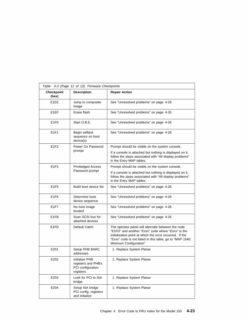
Table 4-3 (Page 11 of 13). Firmware Checkpoints
Checkpoint(hex)
Description Repair Action
E1EE Jump to compositeimage
See “Unresolved problems” on page 4-26
E1EF Erase flash See “Unresolved problems” on page 4-26
E1F0 Start O.B.E. See “Unresolved problems” on page 4-26
E1F1 Begin selftestsequence on bootdevice(s)
See “Unresolved problems” on page 4-26
E1F2 Power On Passwordprompt
Prompt should be visible on the system console.
If a console is attached but nothing is displayed on it,follow the steps associated with “All display problems”in the Entry MAP tables.
E1F3 Priviledged AccessPassword prompt
Prompt should be visible on the system console.
If a console is attached but nothing is displayed on it,follow the steps associated with “All display problems”in the Entry MAP tables.
E1F5 Build boot device list See “Unresolved problems” on page 4-26
E1F6 Determine bootdevice sequence
See “Unresolved problems” on page 4-26
E1F7 No boot imagelocated
See “Unresolved problems” on page 4-26
E1FB Scan SCSI bus forattached devices
See “Unresolved problems” on page 4-26
E1FD Default Catch The operator panel will alternate between the code“E1FD” and another “Exxx” code where “Exxx” is theinitialization point at which the error occurred. If the“Exxx” code is not listed in this table, go to “MAP 1540:Minimum Configuration”
E201 Setup PHB BARCaddresses
1. Replace System Planar
E202 Initialize PHBregisters and PHB'sPCI configurationregisters
1. Replace System Planar
E203 Look for PCI to ISAbridge
1. Replace System Planar
E204 Setup ISA bridgePCI config. registersand initialize
1. Replace System Planar
Chapter 4. Error Code to FRU Index for the Model 150 4-23

Table 4-3 (Page 12 of 13). Firmware Checkpoints
Checkpoint(hex)
Description Repair Action
E206 Look for PRISM onPCG and switch to50MHz
1. Replace System Planar
E207 Setup Data gathermode and 64/32-bitmode on PCG
1. Replace System Planar
E208 Assign bus numberon PCG
1. Replace System Planar
E209 Assign PCI I/Oaddresses on PCI
1. Replace System Planar
E20A Assign PCI I/Oaddresses on PCG
1. Replace System Planar
E20B Check MCERs stuckat fault
1. Replace System Card
E20C Testing L2 cache 1. Replace CPU Card
E210 Processors L1 datacache array testfails. System Hangs.
1. Replace System Planar
E211 IPL ROS CRCchecking
1. Replace System Planar
E212 Processor POST 1. Replace CPU Card
E213 Initial memoryconfiguration
See “MAP 1240: Memory Problem Resolution” onpage 2-12
E214 Memory test See “MAP 1240: Memory Problem Resolution” onpage 2-12
E216 Copy ROS intoRAM. SetupTranslation and Cenvironment
1. Replace Memory Card
E21A System has somegood memory
1. See “Unresolved problems” on page 4-26
E220 Final memoryconfiguration
See “MAP 1240: Memory Problem Resolution” onpage 2-12
E240 Setup Winbond ISAbridge
1. Replace System Planar
E241 Reset PCI Bus 1. Replace System Planar
E242 Initialize ISA DMAchannel
1. Replace System Planar
4-24 7043 43P Series Service Guide

Table 4-3 (Page 13 of 13). Firmware Checkpoints
Checkpoint(hex)
Description Repair Action
E243 Set up Grackleconfigurationregisters
1. Replace System Planar
E244 Enable systemspeaker and send abeep
1. Replace System Planar
E246 System firmwarecorrupted, takerecover path
1. Replace System Planar
E247 Capture DIMMSPDs into NVRAM
1. Replace System Planar
E249 Enter recover path'smain code
1. Replace System Planar
E24C L2 cache array testfails. System hangs.
1. Replace System Planar
E24D L2 cache array testfails. Systemhangs.
1. Replace System Planar
E298 Take firmware softload path
1. Replace Softload Image
E299 Start C codeexecution.
See “Unresolved problems” on page 4-26
E3xx Memory test See “MAP 1240: Memory Problem Resolution” onpage 2-12
E440 Validate nvram,initialize partitions asneeded
1. Verify that the system firmware is at the currentrelease level. Update as necessary.
2. See “Unresolved problems” on page 4-26
E441 Generate /optionsnode nvramconfigurationvariable properties
1. Verify that the system firmware is at the currentrelease level. Update as necessary.
2. See “Unresolved problems” on page 4-26
E442 Validate nvrampartitions
1. Verify that the system firmware is at the currentrelease level. Update as necessary.
2. See “Unresolved problems” on page 4-26
E443 Generate nvramconfigurationvariable dictionarywords
1. Suspect a system firmware problem. If problempersists, verify that the system firmware is atcurrent release level, update downlevel systemfirmware.
2. See “Unresolved problems” on page 4-26
Chapter 4. Error Code to FRU Index for the Model 150 4-25

Unresolved problems: Go to MAP 1540A or 1540B for any of the followingconditions:
� A 4-digit code in the range of “E100” through “EFFF” is displayed on the operatorpanel display but is not listed in Table 4-3 on page 4-13.
� A 4-digit code is displayed and is listed in Table 4-3 on page 4-13, but there areno repair actions or FRUs listed for the code.
� All of the FRUs listed in repair actions have been replaced and the problem hasnot been corrected.
4-26 7043 43P Series Service Guide
Boot Problems/Concerns
Depending on the boot device, a checkpoint may be displayed on the operator panelfor an extended period of time while the boot image is retrieved from the device. Thisis particularly true tape and network boot attempts. If booting from CDROM or tape,watch for activity on the drive's LED indicator. A blinking LED means that the loadingof either the boot image or additional information required by the operating systembeing booted is still in progess. If the checkpoint is displayed for an extended periodof time and the drive LED is not indicating any activity there may be a problemloading the boot image from the device.
Note: For network boot attempts, if the system is not connected to an activenetwork or if the target server is inaccessible (this can also result from incorrect IPparameters being supplied), the system still attempts to boot and because time-outdurations are necessarily long to accommodate retries, the system may appear to behung.
This procedure assumes that a CD-ROM drive is installed and a DiagnosticsCD-ROM is available.
1. Restart the system and get to the Firmware SMS Main Menu. Select Multiboot.� Check if the intended boot device is correctly specified in the boot sequence.� If the intended boot device is not correctly identified in the boot sequence,
add it to the boot sequence using the SMS menus (if the intended bootdevice cannot be added to the boot sequence go to step 3).
� If attempting to boot from the network go to step 2.� If attempting to boot from a disk drive or CD-ROM go to step 3.
2. If attempting to boot from the network:� Verify that IP parameters are correct.� Attempt to "Ping" the target server using the SMS "Ping" utility. If the ping is
successful, have network administrator verify the server configuration for thisclient.
� Turn power Off, then On and retry the boot operation.� Check network cabling to adapter.
3. Try to boot and run standalone diagnostics against the system, particularlyagainst the intended boot device.� If the intended boot device is not listed in the "NEW RESOURCE" list go to
"MAP 0290: Missing Resource Problem Resolution" in the DiagnosticsInformation for Multiple Bus Systems.
� If a SRN, not an 8-digit error code, is reported, go to the DiagnosticsInformation for Multiple Bus Systems manual.
� If the diagnostics are successful, it may be necessary to perform anoperating system specific recovery process, or reinstall the operating system.
� If unable to load standalone diagnostics:
Chapter 4. Error Code to FRU Index for the Model 150 4-27

a. Verify proper SCSI bus termination.
b. Check SCSI cabling.
c. It is possible that another attached SCSI device is causing the problem.
� Disconnect the signal and power cables from any other SCSI devicesattached to the SCSI adapter that the CD-ROM drive is attached to.
� Try to boot the standalone diagnostics again.� If unable to load standalone diagnostics go to step 4.� If standalone diagnostics load, one of the disconnected devices removed
is causing the problem. Reconnect the devices one at a time and retrythe boot operation until the problem recurs and replace the device thatcaused the problem. (If the problem appears to be one of the SCSIdevices, be aware it could be either the SCSI device or the SCSIadapter). Go to "MAP 0410: Repair Checkout" in the DiagnosticsInformation for Multiple Bus Systems.
4. It is possible that another installed adapter is causing the problem.� Remove all installed adapters except the one the CD-ROM drive is attached
to and the one used for the console.� Try to boot the standalone diagnostics again.� If unable to load standalone diagnostics go to step 5.� If standalone diagnostics load, re-install adapters (and attached devices as
applicable) one at a time and retry the boot operation until the problemrecurs. Then replace the adapter or device that caused the problem (systemboard can also cause the device or adapter to fail). Go to "MAP 0410: RepairCheckout" in the Diagnostics Information for Multiple Bus Systems.
5. Either the CD-ROM drive, SCSI adapter, the graphics adapter, or the systemboard is most likely defective. A tty terminal attached to the serial port also canbe used to determine if the graphics adapters is causing the problem. This isdone by removing the graphics adapter, attaching a tty to the serial, and retryingstandalone diagnostics. If the standalone diagnostics load, the graphic adaptershould be replaced.� If the CD-ROM drive is attached to a SCSI adapter card rather than the
integrated SCSI adapter on the system board.– Replace SCSI adapter.– Replace riser card.
� Replace system board.� If you replaced the indicated FRUs and the problem is still not corrected, or
the above descriptions did not address your particular situation, go to“MAP1540: Minimum Configuration” on page 2-21.
� Go to "MAP 0410: Repair Checkout" in the Diagnostics Information forMultiple Bus Systems.
4-28 7043 43P Series Service Guide

Chapter 5. Location Codes (Model 150 only)
This system unit uses physical location codes in conjunction with AIX location codesto provide mapping of the failing field replaceable units. The location codes areproduced by the system unit's firmware and AIX.
Physical Location Codes
Physical location codes provide a mapping of logical functions in a platform (orexpansion sites for logical functions, such as connectors or ports) to their specificlocations within the physical structure of the platform.
Location Code Format
The format for the location code is an alphanumeric string of variable length,consisting of a series of location identifiers, separated by the standard dash (-) orslash (/) character. The series is hierarchical; that is, each location identifier in thestring is a physical child of the one preceding it.
� The - (dash) separator character represents a normal structural relationshipwhere the child is a separate physical package and it plugs into (or is connectedto) the parent. For example, P1-C1 is a CPU card (C1) plugged into a planar(P1), or P1-M1 is a memory card (M1) plugged into a planar (P1).
� The / (slash) separator character separates the base location code of a functionfrom any extended location information. A group of logical devices can have thesame base location code because they are all on the same physical package,but may require extended location information to describe the connectors theysupport. For example, P2/S1 describes the location of the serial port 1 controllerand its connector (S1), which is located on planar P2 (its base location code),but the / indicates that further devices can be connected to it at the external S1serial connector. The keyboard controller and its connector likewise havelocation code P2/K1, which means they have the same base location code (P2)as serial port 1, but a different external connector. In contrast, the location codeP2-K1 actually points to the device connected to connector K1; that is, thekeyboard. The location code P2/Z1 indicates an integrated SCSI controller whichdrives connector Z1, while location codes of P2-Z1-... point to the actual SCSIbus and devices.
Each location identifier consists of one alpha prefix character that identifies a locationtype, and a decimal integer number (typically one or two digits) that identifies aspecific instance of this location type. Certain location types may also supportsecondary sub-locations, which are indicated by appending a period (".") characterand a sub-location instance number.
Chapter 5. Location Codes (Model 150 only) 5-1

Specifically, the format of a location code is defined as follows:
pn[.n][- or /]pn[.n][- or /]...
Where p is a defined alpha location type prefix, n is a location instance number, and[.n] is a sub-location instance number (where applicable). Sub-location notation isused only for location types which have clearly defined and limited expansion sites;for example, memory module slots on a memory card. Primarily, the [.n] sub-locationnotation is intended for use as an abbreviation of the location code in cases where:
1. Based on the device structure, the abbreviated sub-location code conveys thesame information in a more concise form than an additional level of locationidentifier - for example:
� P1-M1.4 (pluggable module 4 on Memory Card 1 on Planar 1), rather thanP1-M1-M4
� P1-C1.1 (pluggable CPU 1 on CPU Card 1 on Planar 1), rather thanP1-C1-C1
� P2-Z1-A3.1 (LUN 1 at SCSI ID 3 on integrated SCSI bus 1 from Planar 2),rather than P2-Z1-A3-A1
2. The sub-location is either a basic physical extension or sub-enclosure of thebase location, but does not represent additional function or connectivity; forexample, a drawer in a rack (U1.2) or a riser card on an I/O board (P2.1).
Name AIXLocationCode
LocationCode
PhysicalConnection
LogicalIdentification
System Planar 00-00 P1
Riser Card P1.1 J39
Memory DIMM 1 00-00 P1-M1 J11
Memory DIMM 2 00-00 P1-M2 J28
Memory DIMM 3 00-00 P1-M3 J19
Memory DIMM 4 00-00 P1-M4 J39
Diskette Drive 01-D1-00-00 P1-D1 J16 Base Address0x03F0
Keyboard 01-K1-00-00 P1-K1 J59 Base Address0x0060
Mouse 01-K1-01-00 P1-O1 J56 Base Address0x0060
Audio Port 01-Q2 P1/Q2
Diskette Port 01-D1 P1/D1 J16 Base Address0x03F0
5-2 7043 43P Series Service Guide

Name AIXLocationCode
LocationCode
PhysicalConnection
LogicalIdentification
Keyboard Port 01-K1-00 P1/K1 J59 Base Address0x0060
Mouse Port 01-K1-01 P1/O1 J56 Base Address0x0060
Serial Port 1 01-S1 P1/S1 J24 Base Address0x03F8
Serial Port 2 01-S2 P1/S2 J23 Base Address0x02F8
Parallel Port 01-R1 P1/R1 J49 Base Address0x0378
Ethernet Port 10-60 P1/E1 J45 Host Bridge ID00,Device 12
SCSI Port 10-80 P1/Z1 J33/J38 Host Bridge ID00,Device 16
Tablet Port 01-Q1 P1/Q1
Card in PCI Slot 1 1P-08 P1.1-I1 J1 PCI Bridge ID01,Device 18
Card in PCI Slot 2 10-b0 P1.1-I2 J2 Host Bridge ID00,Device 22
Card in PCI Slot 3 10-90 P1.1-I3 J3 Host Bridge ID00,Device 18
Card in PCI Slot 4 1P-18 P1.1-I4 J5 PCI Bridge ID01,Device 19
Card in PCI Slot 5 1P-10 P1.1-I5 J4 PCI Bridge ID01,Device 19
Base CDROM in Bay2
P1-Z1-A3 Primary SCSI Bus ID3
Media Drive in Bay 3 P1-Z1-A2 orA6
Primary SCSI Bus ID2 or 6
DASD in Bay 4 P1-Z1-A4 Primary SCSI Bus ID4
DASD in Bay 5 P1-Z1-A5 Primary SCSI Bus ID5
Fan # 1 F1 J27/J30
Operator Panel L1 J41
Power Supply V1 J7/J8/J2/J9
Chapter 5. Location Codes (Model 150 only) 5-3

AIX Location Codes
The basic formats of the AIX location codes are:
� For non-SCSI devices/drives
AB-CD-EF-GH
� For SCSI devices/drives
AB-CD-EF-G,H
For planars, cards, and non-SCSI devices the location code is defined as:
AB-CD-EF-GH
| | | |
| | | Device/FRU/Port ID
| | Connector ID
| devfunc Number, Adapter Number or Physical Location
Bus Type or PCI Parent Bus
� The AB value identifies a bus type or PCI parent bus as assigned by thefirmware.
� The CD value identifies adapter number, adapter's devfunc number, or physicallocation. The devfunc number is defined as the PCI device number times 8, plusthe function number.
� The EF value identifies a connector.
� The GH value identifies a port, address, device, or FRU.
Adapters and cards are identified with just AB-CD.
The possible values for AB are:
The possible values for CD depend on the adapter/card.
For pluggable PCI adapters/cards, CD is the device's devfunc number (PCI devicenumber times 8, plus the function number). The C and D are characters in the range
00 Processor bus01 ISA bus02 EISA bus03 MCA bus04 PCI bus used in the case where the PCI bus cannot be identified05 PCMCIA busesxy For PCI adapters where x is equal to or greater than 1. The x and y are characters in the
range of 0-9, A-H, J-N, P-Z (O, I, and lower case are omitted) and are equal to the parentbus's ibm, aix-loc Open Firmware Property.
5-4 7043 43P Series Service Guide

of 0-9, and A-F (hex numbers). This allows the location code to uniquely identifymultiple adapters on individual PCI cards.
For pluggable ISA adapters, CD is equal to the order the ISA cardsdefined/configured either by SMIT or the ISA Adapter Configuration Service Aid.
For integrated ISA adapters, CD is equal to a unique code identifying the ISAadapter. In most cases this is equal to the adapter's physical location code. In caseswhere a physical location code is not available, CD is be FF.
EF is the connector ID. It is used to identify the adapter's connector that a resourceis attached to.
GH is used to identify a port, device, or FRU. For example:
� For async devices GH defines the port on the fanout box. The values are 00 to15.
� For a diskette drive H defines which diskette drive 1 or 2. G is always 0.
� For all other devices GH is equal to 00.
For integrated adapter, EF-GH is the same as the definition for a pluggable adapter.For example, the location code for a diskette drive is 01-D1-00-00. A seconddiskette drive is 01-D1-00-01.
For SCSI the location code is defined as:
AB-CD-EF-G,H
| | | | |
| | | | Logical Unit address of the SCSI Device
| | | Control Unit Address of the SCSI Device
| | Connector ID
| devfunc Number, Adapter Number or Physical Location
Bus Type or PCI Parent Bus
Where AB-CD-EF are the same as non-SCSI devices.
G defines the control unit address of the device. Values of 0 to 15 are valid.
H defines the logical unit address of the device. Values of 0 to 255 are valid.
There is also a bus location code that is generated as '00-XXXXXXXX' whereXXXXXXXX is equivalent to the node's unit address.
Chapter 5. Location Codes (Model 150 only) 5-5

5-6 7043 43P Series Service Guide

Chapter 6. Loading the System Diagnostics
If no keys are pressed after the system unit power is turned on, the system unitsearches a list of devices (the default boot list ) for a bootable image. If a bootableimage is found, then the system unit loads and starts the operating system. This iscalled a normal boot .
The system unit can also be booted from a custom boot list , which can be changedthrough the System Management Services.
If certain keys are pressed during system startup, the system unit searches thedefault or custom boot list for a bootable image to start in service mode instead ofnormal mode. After a successful service mode boot, the diagnostic programs arestarted automatically.
The following pages describe the default and custom boot lists, and how to boot fromthese in either normal or service mode.
Default Boot List
The default boot list is composed of the first device found of each of the followingtypes:
1. Diskette drive
2. CD-ROM drive
3. Disk Drive
4. Network device
If this default boot list is used during system startup, the system unit attempts to bootfrom the diskette drive, then the first CD-ROM drive encountered, then the first diskdrive encountered, and finally the first network connection encountered.
Custom Boot List
The contents of the custom boot list can be defined by using the graphical SystemManagement Services or the text-based System Management Services When thecustom boot list is utilized during system startup, system unit attempts to boot in turnfrom each specific device in the custom boot list.
Note: Only the specific devices contained in the custom boot list are checked for abootable image. Other devices of the same type are not searched for abootable image unless they are also specified in the custom boot list. Refer
Chapter 6. Loading the System Diagnostics 6-1

to Chapter 7, “System Management Services” on page 7-1 for moreinformation on custom boot lists.
If no bootable image is found in the custom boot list, then the system restarts andattempts to boot again.
If the custom boot list is discovered to be corrupted, the system rebuilds the customboot list according to the default boot list.
Service Mode Boot: Loading Diagnostics
The system unit can be booted in service mode (instead of normal mode ) fromeither the default boot list or custom boot list. After a successful service mode boot,the diagnostic programs are started automatically.
Booting in Service Mode from the Default Boot List
To boot in service mode from the default boot list, do the following:
1. Before stopping the programs and operating system, notify your systemadministrator and users that the system is going to be shut down.
2. Insert the diagnostic CD-ROM into the CD-ROM drive, if you intend to runstandalone diagnostics.
3. Turn off the system.
4. Wait 30 seconds, then turn on the system.
5. When the keyboard indicator appears during startup, press the F5 key if thesystem console is a directly-attached keyboard, or the 5 key if the systemconsole is an ASCII terminal.
6. Enter any passwords.
Diagnostics loaded from CD-ROM are called standalone diagnostics. Since thedefault boot list checks the CD-ROM drive before the disk drive, this procedure isused to start standalone diagnostics.
6-2 7043 43P Series Service Guide

Booting in Service Mode from the Custom Boot List
To boot in service mode from the custom boot list, do the following:
1. Verify with the system administrator and users that all programs are to bestopped, then do so.
2. Turn off the system.
3. Wait 30 seconds, then turn on the system.
4. When the keyboard indicator appears during startup, press the F6 key if thesystem console is a directly-attached keyboard, or the 6 key if the systemconsole is an ASCII terminal.
5. Enter any passwords.
Diagnostics loaded from a disk drive or network are called online diagnostics.(Online diagnostics can be used only if AIX is installed.) Since the custom boot listshould list the disk drive or network device before the CD-ROM drive, this procedureis used to start online diagnostics. To ensure that using the custom boot list startsonline diagnostics, do not insert the diagnostics CD-ROM.
Chapter 6. Loading the System Diagnostics 6-3

Standalone vs. Online Diagnostics
When the system unit attempts to boot in service mode (from either the default orcustom boot list) and locates a diagnostics CD-ROM before any other bootableimage, then the system unit starts standalone diagnostics .
Standalone diagnostics can be used on system units installed with any supportedoperating system.
When the system unit attempts to boot in service mode (from either the default orcustom boot list) and first locates a bootable image on disk drive or networkconnection, then the system unit starts online diagnostics .
Online diagnostics can only be used on system units installed with the AIX operatingsystem.
Because the type of diagnostics started (standalone or online) depends on thesource from which they are loaded, changing the boot list used during system startupcan affect which diagnostics are run.
Recommended Boot Options
The procedures under “Service Mode Boot: Loading Diagnostics” on page 6-2produce the following recommended results:
� Default boot list (F5 or 5 key) with diagnostics CD-ROM inserted loadsStandalone Diagnostics .
� Custom boot list (F6 or 6 key) without diagnostics CD-ROM inserted loadsOnline Diagnostics , if AIX is installed on a device in the custom boot list.
6-4 7043 43P Series Service Guide
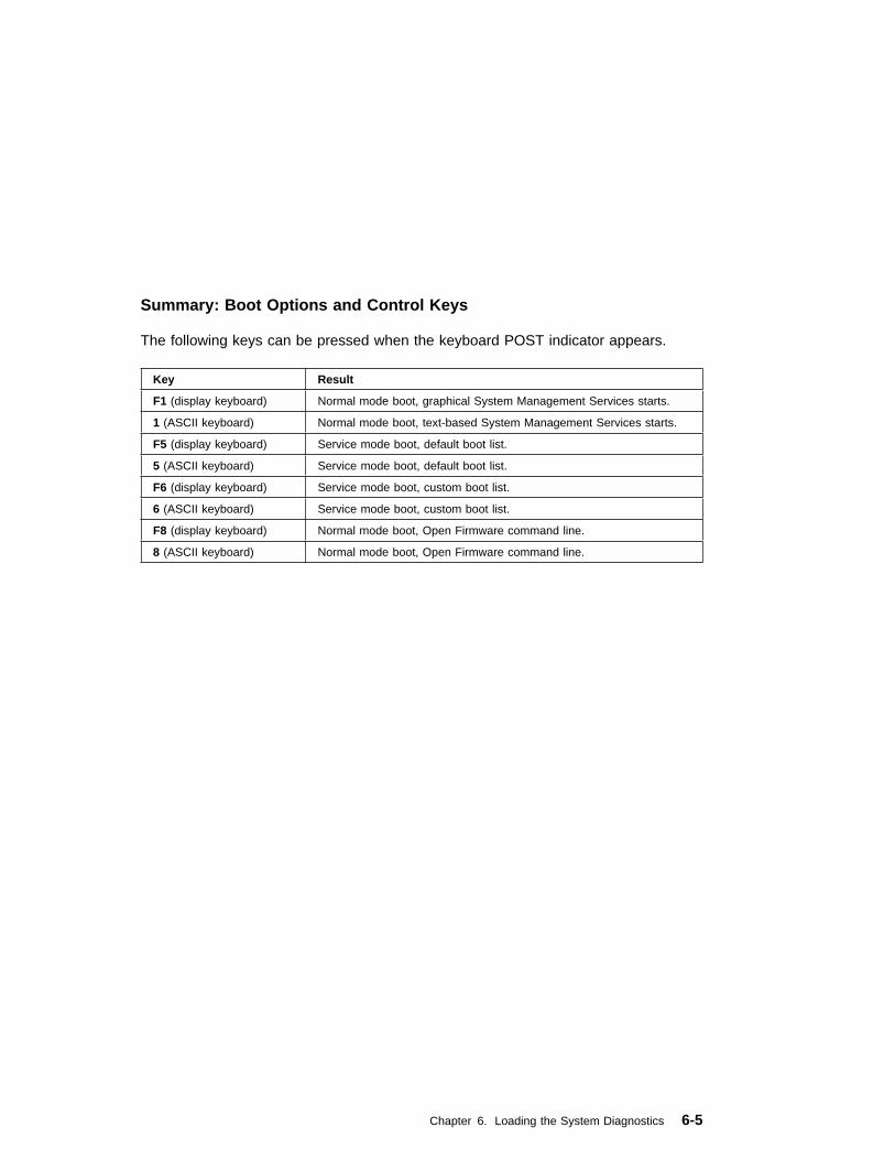
Summary: Boot Options and Control Keys
The following keys can be pressed when the keyboard POST indicator appears.
Key Result
F1 (display keyboard) Normal mode boot, graphical System Management Services starts.
1 (ASCII keyboard) Normal mode boot, text-based System Management Services starts.
F5 (display keyboard) Service mode boot, default boot list.
5 (ASCII keyboard) Service mode boot, default boot list.
F6 (display keyboard) Service mode boot, custom boot list.
6 (ASCII keyboard) Service mode boot, custom boot list.
F8 (display keyboard) Normal mode boot, Open Firmware command line.
8 (ASCII keyboard) Normal mode boot, Open Firmware command line.
Chapter 6. Loading the System Diagnostics 6-5

6-6 7043 43P Series Service Guide

Chapter 7. System Management Services
The System Management Services make it possible for you to view informationabout your computer and to perform such tasks as setting passwords and changingdevice configurations.
If you have chosen a graphical display as your system console, you can use thegraphical System Management Services described below. If you are using an ASCIIdisplay as your system console, see “Text-Based System Management Services” onpage 7-26.
Graphical System Management Services
To start the Open Firmware command line or graphical System ManagementServices, turn on or restart the computer.
The firmware version installed in your system unit is displayed at the bottomright-hand corner of the initial logo screen. Please note the version number;processor upgrades may require a specified version of firmware to be installed inyour system unit. (Update System Firmware is an option under the Utilities menu inthe System Management Services.)
After the logo is displayed, initialization icons appear across the bottom of thescreen.
To enter the graphical System Management Services, you must press the F1 keyafter the keyboard icon appears during startup.
If you have pressed the F1 key, the System Management Services appears after theinitialization and power-on self test (POST) are complete.
Note: If you have installed a privileged-access password, you are be prompted forthis password before gaining access to the System Management Servicesmenu.
Chapter 7. System Management Services 7-1
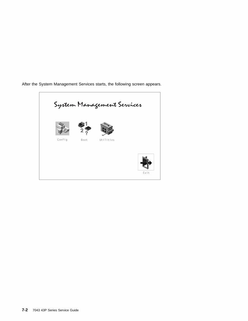
After the System Management Services starts, the following screen appears.
7-2 7043 43P Series Service Guide

The System Management Services screen contains the following choices.
Config : Enables you to view your system setup.
Multi-Boot (Model 150 only) : Enables you to set and view thedefault operating system, modify the boot sequence, access theOpen Firmware command prompt, and other options.
Boot (Model 140 and Model 240) : Allows you to modify theboot sequence.
Utilities : Enables you to set and remove passwords, controlthe playing of system tones, enable the unattended start mode,set and view the addresses of your system's SCSI controllers,select the active console, view or clear the firmware error log,and update your system unit's firmware program.
Exit : Returns you to the previous screen.
To select an icon, move the cursor with the arrow keys to choose which icon ishighlighted, then press the Enter key. You can also select an icon by clicking on itwith your left mouse button. To leave the current screen, either press the Esc key orselect the Exit icon.
Chapter 7. System Management Services 7-3

Config
Selecting this icon makes it possible for you to view information about the setup ofyour system unit. A list similar to the following appears when you select the Configicon.
7-4 7043 43P Series Service Guide
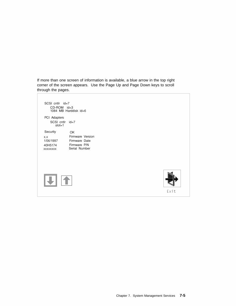
If more than one screen of information is available, a blue arrow in the top rightcorner of the screen appears. Use the Page Up and Page Down keys to scrollthrough the pages.
Chapter 7. System Management Services 7-5
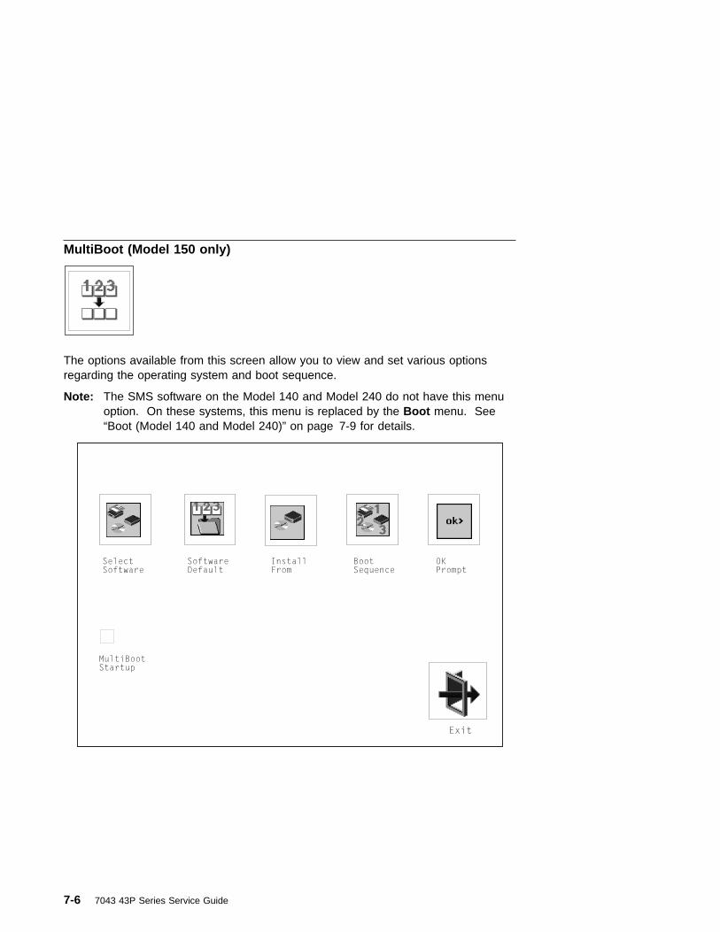
MultiBoot (Model 150 only)
The options available from this screen allow you to view and set various optionsregarding the operating system and boot sequence.
Note: The SMS software on the Model 140 and Model 240 do not have this menuoption. On these systems, this menu is replaced by the Boot menu. See“Boot (Model 140 and Model 240)” on page 7-9 for details.
7-6 7043 43P Series Service Guide

The following describes the choices available on this screen.
Select Software: The Select Software option, if supported bythe operating system, allows you to choose which operatingsystem to use. This option is supported by AIX. Not alloperating systems support this option.
If you receive an informational message saying that nooperating system is installed, then the system information innon-volatile storage may have been lost. This can happen ifthe battery has been removed. To correct this situation, referto the bootlist reference in your AIX operating systemdocumentation.
Software Default: This option, if supported by the operatingsystem, enables you to select an operating system as thedefault operating system for your system unit.
Install From: Enables you to select a media drive from whichto install an operating system.
Chapter 7. System Management Services 7-7

Boot Sequence: Enables you to view and change the customboot list (the sequence in which devices are searched foroperating system code). You may choose from 1 to 5 devicesfor the custom boot list.
The default boot sequence is:
Note:
1. The primary diskette drive.
2. The CD-ROM drive.
3. Tape drive.
4. Hard disk drive.
5. Network device.
To change the custom boot list, enter a new order in the Newcolumn, then click on the Save icon. The list of boot devices isupdated to reflect the new order.
Attention:
To change the custom boot list back to the default values, clickon Default . If you change your startup sequence, you must beextremely careful when performing write operations (forexample, copying, saving, or formatting). You can accidentallyoverwrite data or programs if you select the wrong drive.
OK Prompt: Enables you to go directly to the Open Firmwarecommand prompt. The Open Firmware command prompt isused for debugging and device driver development. For moreinformation about the operation of the Open Firmwarecommand prompt, refer to IEEE Standard 1275.
Multiboot Start: Clicking on this button toggles whether theMultiboot menu appears automatically at startup.
7-8 7043 43P Series Service Guide

Boot (Model 140 and Model 240)
This selection enables you to view and change the custom boot list (the sequence inwhich devices are searched for operating system startup code).
Chapter 7. System Management Services 7-9

Attention: If you change your startup sequence, you must be extremely carefulwhen performing write operations (for example, copying, saving, orformatting). You can accidentally overwrite data or programs if you select thewrong drive.
The default boot list consists of the first device found of each of the following types.
� Diskette drive
� CD-ROM drive
� Hard disk drive
� Network device.
To change the custom boot list, enter a new order in the New column, then selectSave. The List of Boot Devices is updated to reflect the order you have chosen.
You can choose 1 to 4 devices for the custom boot list. To change the bootsequence back to the default values, select Default . (The default sequence isautomatically saved.)
Attention: If no user-defined boot-list exists, and the privileged-access passwordhas been enabled, you are asked for the privileged-access password atstartup every time you boot up your system. See “Privileged-AccessPassword” on page 7-15 for more information on the privileged-accesspassword.
7-10 7043 43P Series Service Guide

Utilities
Selecting this icon enables you to perform various tasks and view additionalinformation about your system unit.
The following describes the choices available on this screen.
Password : Enables you to set password protection for turningon the system unit and for using system administration tools.
Audio (Model 140 and Model 240 only) : Enables you to turnon or off the system tones heard when the system is turned on.
Hard Disk Spin Up Delay (Model 150 only) : Enables you tochange the spin up delay for SCSI hard disk drives attached toyour system.
Chapter 7. System Management Services 7-11

Error Log : Enables you to view and clear the firmware errorlog information for your system unit.
RIPL (Remote Initial Program Load): Allows you to select aremote system from which to load programs via a networkadapter when your system unit is first turned on. This optionalso allows you to configure network adapters which requiresetup.
SCSI ID: Allows you to view and change the addresses (IDs) ofthe SCSI controllers attached to your system unit.
Update : Allows you to update the system firmware program.
Console : If you have more than one keyboard and displayattached to your system unit, or if you have an ASCII terminalattached to your system unit in addition to a keyboard anddisplay, this tool allows you to define which one is active.
7-12 7043 43P Series Service Guide

Password
When you select this icon, the following screen is displayed.
Power-On Password
Setting a power-on password helps protect information stored in your system unit. Ifa power-on password is set for your system unit, the Power-On status icon is shownin the locked position; if a power-on password is not set, then the Power-On statusicon is shown in the unlocked position (as in the screen above).
When you select the Entry icon, a screen with 8 empty boxes appears. Type yourpassword in these boxes. You can use any combination of up to eight characters(A–Z, a–z, and 0–9) for your password. As you type a character, a key appears inthe box.
Chapter 7. System Management Services 7-13

Press Enter when you are finished; you must type the password again forverification.
If you make a mistake, press the Esc key and start again.
After you have entered and verified the password, the power-on password statusicon flashes and changes to the locked position to indicate that the power-onpassword is installed.
If you previously had set a power-on password and want to remove it, select theRemove icon.
Notes:
1. If you want to disable an installed power-on password (but not erase it) move thepower-on password jumper as described in the section beginning on 1-1.Moving the jumper back to the default position re-enables the power-onpassword, unless it has been removed in the System Management ServicesUtilities or by removing the battery.
2. If you forget the power-on password, you can erase the password by shuttingdown the system unit and removing the battery for at least 30 seconds. See“Battery” on page 8-36 for details.
3. The system unit power cable must be disconnected before removing the battery.
A password becomes effective only after the system is turned off and back on again.
7-14 7043 43P Series Service Guide

Remote Mode : The remote mode, when enabled, allows the system to start fromthe defined boot device. This mode is ideal for network servers and other systemunits that operate unattended. You must set a power-on password before you canenable the remote mode. When the remote mode is set, the icon changes toRemote <On> .
If you remove the power-on password, the remote mode is automatically reset, andthe icon returns to Remote <Off> .
Note: In order to use the remote mode feature for booting unattended devices, youmust enable the automatic power-up feature. See the User's Guide forinstructions on enabling the automatic power-up feature, which allows thesystem unit to turn on whenever AC power is applied to the system (insteadof having the system unit wait for the power button to be pushed).
Privileged-Access Password
The privileged-access password protects against the unauthorized starting of thesystem programs. To set the privileged-access password, you must first change ajumper on the system board. See “Front View without Covers” on page 1-3 to locateand change the password-enabling jumper, then return here.
If the password-enabling jumper has been changed, select the Entry icon to set andverify the privileged-access password.
When you select the Entry icon, a screen with 8 empty boxes appears. Type yourpassword in these boxes. You can use any combination of up to eight characters(A–Z, a–z, and 0–9) for your password. As you type a character, a key appears inthe box.
Chapter 7. System Management Services 7-15

Press Enter when you are finished; you must type the password again forverification.
If you make a mistake, press the Esc key and start again.
Note: If an error occurs when you attempt to set the privileged-access password,then make sure the password-enabling jumper has been changed. (See theUser's Guide for instructions on changing the password-enabling jumper.)
After you have entered and verified the password, the privileged-access passwordicon flashes and changes to the locked position to indicate that your system unit nowrequires the password you just entered before running system programs.
Attention: Once the password-enabling jumper has been changed and theprivileged-access password has been set, great care must be taken topreserve the privileged-access password. If you set the privileged-accesspassword and later misplace it, your system must be returned for service.
In order to prevent loss of system use, please record the privileged-accesspassword immediately whenever it is changed.
Attention: If no user-defined boot-list exists, and the privileged-access passwordhas been enabled, you are asked for the privileged-access password atstartup every time you boot up your system.
Moving the password-enabling jumper back to the default position does not disableor erase the privileged-access password. Removing the jumper or moving thejumper back to the default position only prohibits changing or disabling this passwordwith the System Management Services.
7-16 7043 43P Series Service Guide

Audio (Model 140 and Model 240 only)
This icon enables you to turn on or off the system tones heard at power-on time. Tochange the audio status, use the arrow keys or mouse to highlight the audio icon,then press the Enter key.
Chapter 7. System Management Services 7-17

Hard Disk Spin Up Delay (Model 150 only)
This selection allows you to change the spin up delay for SCSI hard disk drivesattached to your system. Spin up delay values can be entered manually or a defaultsetting can be used. All values are measured in seconds. The default is twoseconds. After you have entered the new Spin up delay values, use the arrow keysto highlight the Save icon and press the Enter key.
7-18 7043 43P Series Service Guide

Error Log
Selecting this icon displays the log of errors your system unit has encountered duringoperations.
Selecting the Clear icon erases the entries in this log.
Chapter 7. System Management Services 7-19

RIPL
Selecting the Remote Initial Program Load (RIPL) icon above gives you access tothe following selections.
The Set Address icon allows you to define addresses from which your system unitcan receive RIPL code.
7-20 7043 43P Series Service Guide

If any of the addresses is incomplete or contains a number other than 0 to 255, anerror message is displayed when you select the Save icon. To clear this error,change the improper address and select Save again.
The Ping icon allows you to confirm that a specified address is valid by sending atest transmission to that address.
After choosing the Ping option, you are asked to indicate which communicationsadapter (Token Ring or Ethernet) should be used to send the test transmission.
Chapter 7. System Management Services 7-21
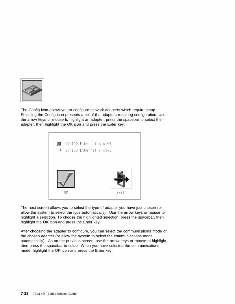
The Config icon allows you to configure network adapters which require setup.Selecting the Config icon presents a list of the adapters requiring configuration. Usethe arrow keys or mouse to highlight an adapter, press the spacebar to select theadapter, then highlight the OK icon and press the Enter key.
The next screen allows you to select the type of adapter you have just chosen (orallow the system to select the type automatically). Use the arrow keys or mouse tohighlight a selection. To choose the highlighted selection, press the spacebar, thenhighlight the OK icon and press the Enter key.
After choosing the adapter to configure, you can select the communications mode ofthe chosen adapter (or allow the system to select the communications modeautomatically). As on the previous screen, use the arrow keys or mouse to highlight,then press the spacebar to select. When you have selected the communicationsmode, highlight the OK icon and press the Enter key.
7-22 7043 43P Series Service Guide
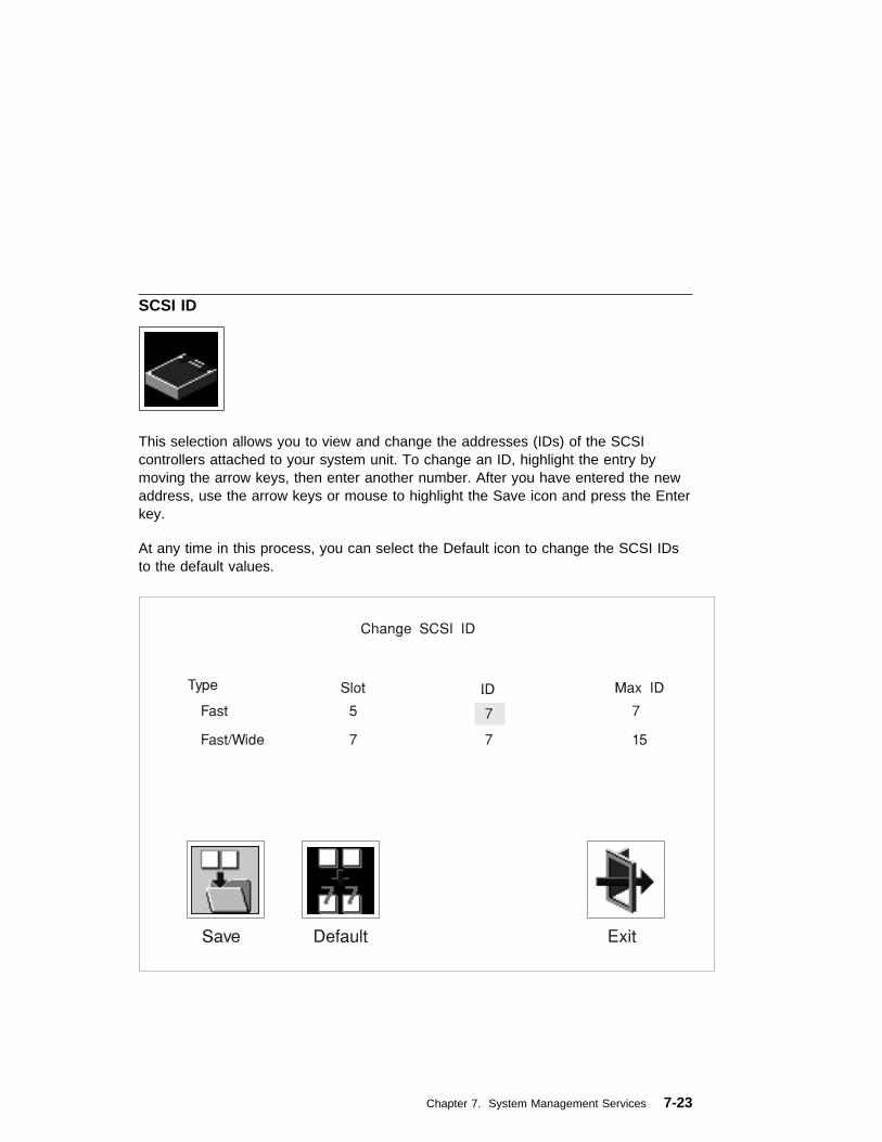
SCSI ID
This selection allows you to view and change the addresses (IDs) of the SCSIcontrollers attached to your system unit. To change an ID, highlight the entry bymoving the arrow keys, then enter another number. After you have entered the newaddress, use the arrow keys or mouse to highlight the Save icon and press the Enterkey.
At any time in this process, you can select the Default icon to change the SCSI IDsto the default values.
Chapter 7. System Management Services 7-23

Firmware Update
This selection allows you to update the firmware in your system unit from an imageon a 3.5 inch diskette.
In order to create a firmware diskette with the latest level of firmware available, see:
http://www.rs6ððð.ibm.com/support/micro
When prompted, insert the firmware update diskette containing the new firmwareimage.
ATTENTION: While the new firmware image is being copied into your system unit,you must not turn off the system unit. Turning off the system unit during the updateprocess may render your system unit inoperable.
After the firmware update is complete, shut down and restart the system unit.
If the firmware update does not complete successfully or the system unit does notrestart after the firmware update, contact your IBM authorized reseller or IBMmarketing representative.
7-24 7043 43P Series Service Guide

Firmware Recovery
If a troubleshooting procedure has indicated that the firmware information in yoursystem unit has been damaged, then you must perform a firmware recovery.
To perform a firmware recovery, do the following:
1. Locate your firmware update diskette.
2. Using another system unit, rename the *.img file on the firmware update disketteto precover.img
3. Make sure your system unit is turned off.
4. Insert the firmware recovery diskette into your system unit.
5. Turn on your system unit.
6. When the keyboard indicator appears, press the 1 key if the system console isan ASCII terminal, or the F1 key if the system console is a directly-attachedkeyboard.
7. When the System Management Services appear, choose Utilities and perform aFirmware Update as described above.
Chapter 7. System Management Services 7-25

Text-Based System Management Services
The text-based Open Firmware command line and System Management Services areavailable if an ASCII terminal is attached to your system unit.
To start the text-based System Management Services instead of the Open Firmwarecommand line, press 1 on the ASCII terminal keyboard when the keyboard textsymbol appears during startup.
After the text-based System Management Services starts, the following screenappears.
Note: The version of firmware currently installed in your system unit is displayed atthe top of each screen in the text-based System Management Services.Please note the version number; processor upgrades may require a specifiedversion of firmware to be installed in your system unit. Update SystemFirmware is an option under the Utilities menu.
à ð
System Management Services
1 Display Configuration
2 Select Boot Devices
3 Utilities
4 Select Language
.------.
|X=Exit|
------'
====>
á ñ
Figure 7-1. Text-based System Management Services - Main Menu (Model 140 and Model 240)
7-26 7043 43P Series Service Guide
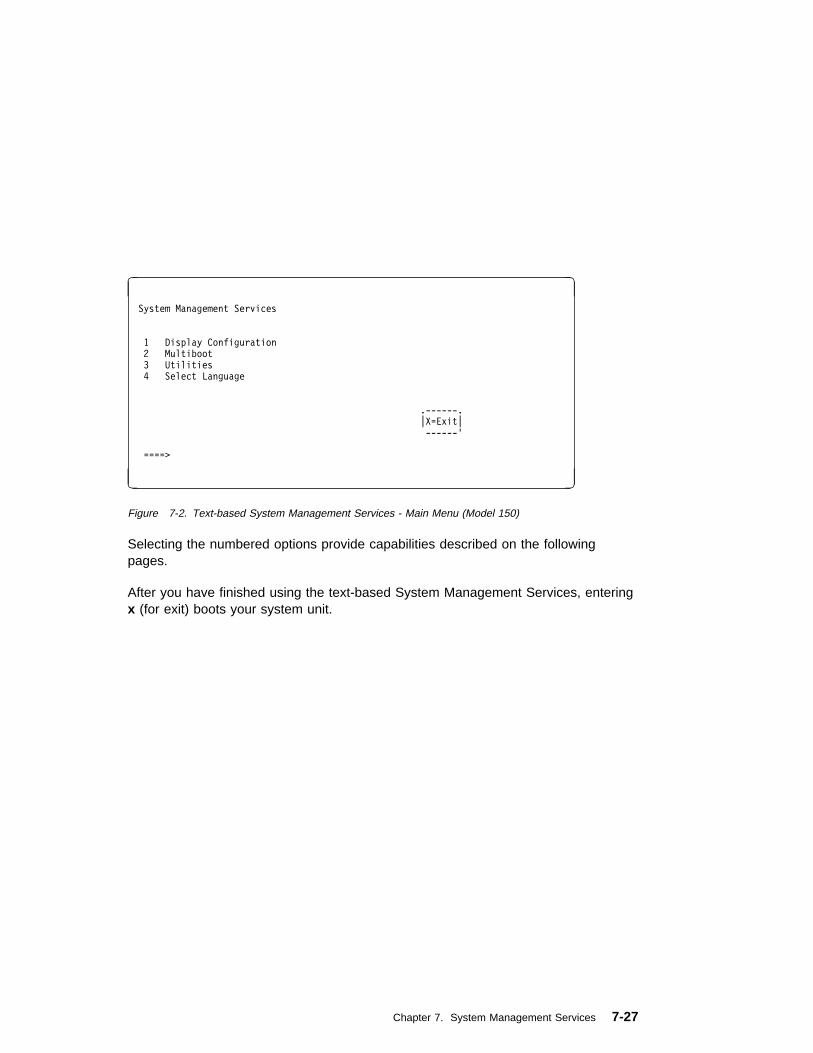
à ð
System Management Services
1 Display Configuration
2 Multiboot
3 Utilities
4 Select Language
.------.
|X=Exit|
------'
====>
á ñ
Figure 7-2. Text-based System Management Services - Main Menu (Model 150)
Selecting the numbered options provide capabilities described on the followingpages.
After you have finished using the text-based System Management Services, enteringx (for exit) boots your system unit.
Chapter 7. System Management Services 7-27
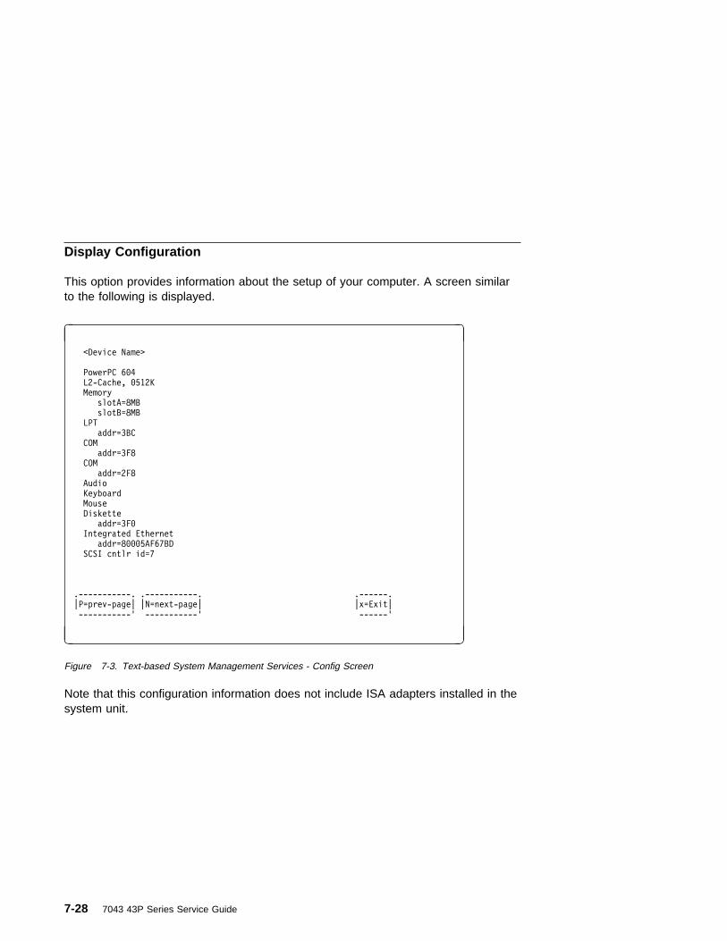
Display Configuration
This option provides information about the setup of your computer. A screen similarto the following is displayed.
à ð
<Device Name>
PowerPC 6ð4
L2-Cache, ð512K
Memory
slotA=8MB
slotB=8MB
LPT
addr=3BC
COM
addr=3F8
COM
addr=2F8
Audio
Keyboard
Mouse
Diskette
addr=3Fð
Integrated Ethernet
addr=8ððð5AF67BD
SCSI cntlr id=7
.-----------. .-----------. .------.
|P=prev-page| |N=next-page| |x=Exit|
-----------' -----------' ------'
á ñ
Figure 7-3. Text-based System Management Services - Config Screen
Note that this configuration information does not include ISA adapters installed in thesystem unit.
7-28 7043 43P Series Service Guide

MultiBoot Menu (Model 150)
The options available from this screen allow you to view and set various optionsregarding the operating system and boot sequence.
Note: The SMS software on the Model 140 and Model 240 do not have this menuoption. On these systems, this menu is replaced by the Boot menu. See“Select Boot Devices” on page 7-30 for details.
à ðMultiboot Menu
1. Select Software
2. Software Default
3. Select Install Device
4. Select Boot Devices
5. OK Prompt
6. Multiboot Startup
.------.
|X=Exit|
------'
===>
á ñ
Figure 7-4. Text-based System Management Services - Multiboot Menu
Select Software : If supported by the operating system, this option shows the namesof the operating system installed. This option may not be supported by all operatingsystems.
In the case of AIX this is a supported option, if you receive a message saying that:
No Operating System Installed
this would mean that information in non-volatile storage could have been lost, aswould happen if the battery had been removed. In order to recreate this value, issuethe bootlist command under AIX with the appropriate parameters as to the locationof the operating system in a particular hard disk. Please see the explanation of thebootlist command in your AIX documentation.
Software Default : If supported by the operating system, lets you select the defaultoperating system to start the system. This option may not be supported by alloperating systems.
Chapter 7. System Management Services 7-29

Select Install Device : Produces a list of devices, for example the CD-ROM, wherethe operating system is installed from. You select one of the devices and the systemsearches the device for an operating system to install and if supported by theoperating system in that device, the name of the operating system displays.
Select Boot Device : Provides a list of devices that can be selected to be stored onthe boot list. Up to 5 devices are supported.
OK Prompt : Provides access to the Open Firmware command prompt.
Multiboot Start Option : Toggles between OFF and ON and selects if the Multibootmenu invokes automatically on startup or not.
Select Boot Devices
This selection enables you to view and change the custom boot list, which is thesequence of devices read at startup time.
à ðSelect Boot Devices
1. Display Current Settings
2. Restore Default Settings
3. Configure 1st Boot Device
4. Configure 2nd Boot Device
5. Configure 3rd Boot Device
6. Configure 4th Boot Device
7. Configure 5th Boot Device
.------.
|X=Exit|
------'
====>
á ñ
Figure 7-5. Text-based System Management Services - Select Boot Devices Menu
Display Current Settings : Lists the current order of devices in the boot list. Thefollowing screen shows an example of this display.
7-30 7043 43P Series Service Guide

à ðCurrent Boot Sequence
1. Diskette
2. Ethernet (Integrated)
3. SCSI CD-ROM id=3 (slot=1)
4. SCSI 5ððMB Hard Disk id=6 (slot=1)
5. SCSI 5ððMB Hard Disk id=5 (slot=5)
.------.
|X=Exit|
------'
===>
á ñ
Figure 7-6. Text-based System Management Services - Boot Sequence Screen
Restore Default Settings : Restores the boot list to the default sequence of:
� The primary diskette drive
� CD-ROM drive
� Tape id=5
� Hard disk drive id=6
� Network device.
Selecting any of the Configure Boot Device options displays the following screen.
Chapter 7. System Management Services 7-31

à ð
Configure Nth Boot Device
Device Number Current Position Device Name
1 1 Diskette
2 2 Ethernet
3 3 SCSI CD-ROM
4 4 SCSI 4.5GB Hard Disk
5 -
.-----------. .-----------. .------.
|P=prev-page| |N=next-page| |X=Exit|
-----------' -----------' ------'
===>
á ñ
Figure 7-7. Text-based System Management Services - Configure Boot Device Screen
Attention: If no user-defined boot-list exists, and the privileged-access passwordhas been enabled, you are asked for the privileged-access password atstartup every time you boot up your system. See “Set Privileged-AccessPassword” on page 7-35 for more information on the privileged-accesspassword.
7-32 7043 43P Series Service Guide

Utilities
The Utilities screen enables you to select from the following system managementtools.
à ð
Utilities
1. Set Password and Unattended Start Mode
2. Audio <ON>
3. Display Error Log
4. Remote Initial Program Load Setup
5. Change SCSI id
6. Update System Firmware
7. Select Console
.------.
|X=Exit|
------'
===>
á ñ
Figure 7-8. Text-based System Management Services - Utilities Menu (Model 140 & Model 240)
à ð
Utilities
1. Set Passwords and Unattended Start Mode
2. SCSI Spin-Up
3. Display Error Log
4. Remote Initial Program Load Setup
5. Change SCSI id
6. Update System Firmware
7. Select Console
.------.
|X=Exit|
------'
===>
á ñ
Figure 7-9. Text-based System Management Services - Utilities Menu (Model 150)
Chapter 7. System Management Services 7-33
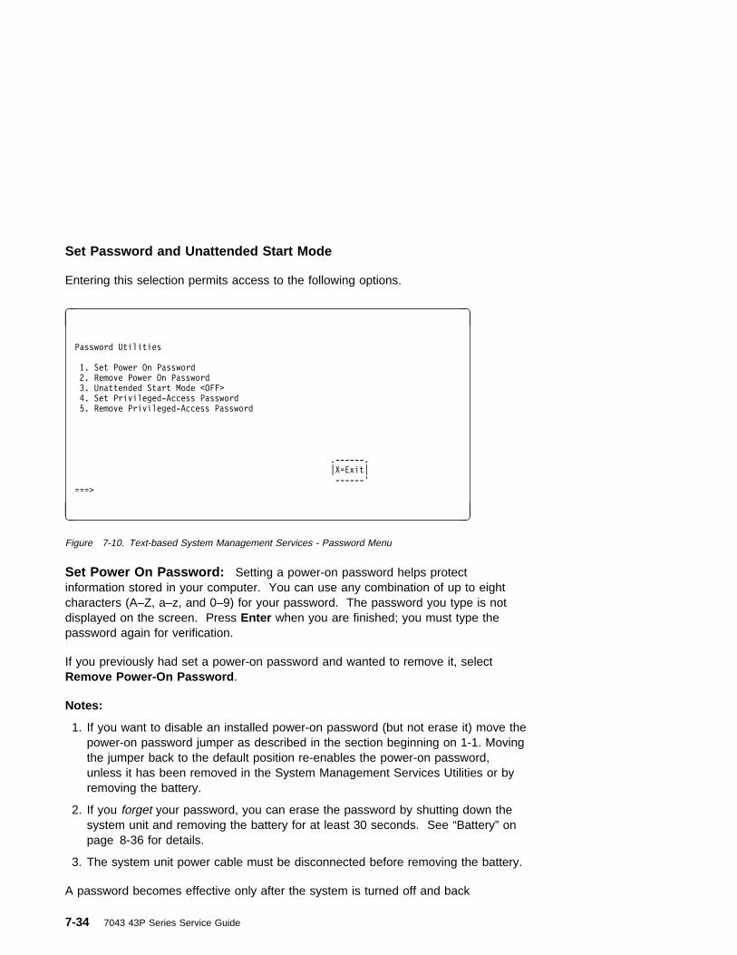
Set Password and Unattended Start Mode
Entering this selection permits access to the following options.
à ð
Password Utilities
1. Set Power On Password
2. Remove Power On Password
3. Unattended Start Mode <OFF>
4. Set Privileged-Access Password
5. Remove Privileged-Access Password
.------.
|X=Exit|
------'
===>
á ñ
Figure 7-10. Text-based System Management Services - Password Menu
Set Power On Password: Setting a power-on password helps protectinformation stored in your computer. You can use any combination of up to eightcharacters (A–Z, a–z, and 0–9) for your password. The password you type is notdisplayed on the screen. Press Enter when you are finished; you must type thepassword again for verification.
If you previously had set a power-on password and wanted to remove it, selectRemove Power-On Password .
Notes:
1. If you want to disable an installed power-on password (but not erase it) move thepower-on password jumper as described in the section beginning on 1-1. Movingthe jumper back to the default position re-enables the power-on password,unless it has been removed in the System Management Services Utilities or byremoving the battery.
2. If you forget your password, you can erase the password by shutting down thesystem unit and removing the battery for at least 30 seconds. See “Battery” onpage 8-36 for details.
3. The system unit power cable must be disconnected before removing the battery.
A password becomes effective only after the system is turned off and back
7-34 7043 43P Series Service Guide

Set Privileged-Access Password: The privileged-access password protectsagainst the unauthorized starting of the system programs.
To set the privileged-access password, you must first change a jumper on yourcomputer's system board. See “Front View without Covers” on page 1-3 to locateand change the password-enabling jumper.
If the password-enabling jumper has been changed, select Set privileged-accesspassword to set and verify the privileged-access password.
Attention: Once the password-enabling jumper has been changed and theprivileged-access password has been set, great care must be taken topreserve the privileged-access password. If you set the privileged-accesspassword and later misplace it, your system must be returned for service.
In order to prevent loss of system use, please record the privileged-accesspassword immediately whenever it is changed.
Attention: If no user-defined boot-list exists, and the privileged-access passwordhas been enabled, you are asked for the privileged-access password atstartup every time you boot up your system.
Moving the password-enabling jumper back to the default position does not disableor erase the privileged-access password. Removing the jumper or moving thejumper back to the default position only prohibits changing or disabling this passwordwith the System Management Services. Removing the battery does not affect thestate of the privileged-access password at all.
If you previously had set a privileged-access password and want to remove it, selectRemove Privileged-Access Password .
Audio (Model 140 and Model 240 only)
Selecting this utility turns on or off the system tones heard at power-on time.
Hard Disk Spin-Up Delay (Model 150 only)
Selecting this utility allows you to adjust the hard disk spin-up delay in your systemunit.
Chapter 7. System Management Services 7-35

Display Error Log
A screen similar to the following is displayed when you select this option. Here, youcan view or clear your computer's error log.
à ð
.----------------------------------------------------------.
| Error Log |
| |
| Date Time ErrorCode Location |
| Entry 1. ð1/ð4/96 12:13:22 25A8ðð11 ðð-ðð |
| Entry 2. no error logged |
----------------------------------------------------------'
.-----------------. .------.
|C=Clear Error Log| |X=Exit|
-----------------' ------'
á ñ
Figure 7-11. Text-based System Management Services - Error Log
7-36 7043 43P Series Service Guide

Remote Initial Program Load Setup
This option allows you to enable and set up the remote startup capability of yourcomputer. First, you are asked to specify the network parameters.
à ð
Network Parameters
1. IP Parameters
2. Adapter Parameters
3. Ping
.------.
|X=Exit|
------'
===>
á ñ
Figure 7-12. Text-based System Management Services - RIPL Setup Menu
Selecting the IP Parameters option displays the following screen.
à ðIP Parameters
1. Client IP Address [ððð.ððð.ððð.ððð]
2. Server IP Address [ððð.ððð.ððð.ððð]
3. Gateway IP Address [ððð.ððð.ððð.ððð]
4. Subnet Mask [ððð.ððð.ððð.ððð]
.------.
|X=Exit|
------'
===>
á ñ
Figure 7-13. Text-based System Management Services - IP Parameters Menu
Chapter 7. System Management Services 7-37

Selecting the Adapter Parameters option allows you to view an adapter's hardwareaddress, as well as configure network adapters that require setup.
à ð
Adapter Parameters
Device HW Address
1. 3Com,3C9ð5 8ððð5AFC67BD
2. token-ring 8ððð32E54A12
.------.
|X=Exit|
------'
á ñ
Figure 7-14. Text-based System Management Services - Adapter Parameters Menu
7-38 7043 43P Series Service Guide

Selecting option 1 (3Com,3C905) displays the following 100Mb Ethernetconfiguration menus:
à ð
3Com Etherlink Fast XL
1. Media Type [Auto]
2. Full Duplex [Auto]
.------.
|X=Exit|
------'
á ñ
Selecting the Media Type option allows you the change the media employed by theEthernet adapter:
à ð
.----------------.
| MEDIA TYPE |
| 1. 1ð BaseT |
| 2. 1ðð Base TX |
| 3. Auto |
----------------'
á ñ
Chapter 7. System Management Services 7-39

Selecting the Full Duplex option allows you to change how the Ethernet adaptercommunicates with the network:
à ð
.----------------.
| Full Duplex |
| 1. Yes |
| 2. No |
| 3. Auto |
----------------'
á ñ
Ping, the last option available from the Network Parameters menu, allows you to testa connection to a remote system unit. After selecting the Ping option, you mustchoose which adapter communicates with the remote system.
à ð
Interface
1. Ethernet
2. Token Ring
===>
á ñ
7-40 7043 43P Series Service Guide

After choosing which adapter to use to ping the remote system, you must provide theaddresses needed to communicate with the remote system.
à ðPing
1. Client IP Address [129.132.4.2ð]
2. Server IP Address [129.132.4.1ð]
3. Gateway IP Address [129.132.4.3ð]
4. Subnet Mask [255.255.255.ð]
.---------. .------.
|E=Execute| |X=Exit|
---------' ------'
===>
á ñ
Change SCSI ID
This option allows you to view and change the addresses of the SCSI controllersattached to you computer.
Update System Firmware
This option allows you to update your system firmware. Note that you must insert adiskette containing the firmware update image after you see the followingconfirmation screen.
In order to create a firmware diskette with the latest level of firmware available, see:
http://www.rs6ððð.ibm.com/support/micro
When prompted, insert the firmware update diskette containing the new firmwareimage.
Chapter 7. System Management Services 7-41

à ð
.--------------------------------------------------------------.
| This selection will update your System Firmware. Do you want |
| to continue? Press Y(Yes) N(No). |
--------------------------------------------------------------'
á ñ
Firmware Recovery: If a troubleshooting procedure has indicated that thefirmware information in your system unit has been damaged, then you must performa firmware recovery.
To perform a firmware recovery, do the following:
1. Locate your firmware update diskette.
2. Using another system unit, rename the *.img file on the firmware update disketteto precover.img
3. Make sure your system unit is turned off.
4. Insert the firmware recovery diskette into your system unit.
5. Turn on your system unit.
6. When the keyboard indicator appears, press the 1 key on the system consoleASCII terminal.
7. When the System Management Services appear, choose Utilities and perform aSystem Firmware Update as described above.
7-42 7043 43P Series Service Guide

Select Console: Selecting this option allows you to define which display is usedby the system for system management.
Select Language
This option allows you to change the language used by the text-based SystemManagement Services screens.
à ð
SELECT LANGUAGE
1. English
2. Francais
3. Deutsch
4. Italiano
5. Espanol
6. Svenska
====> .------.
|x=Exit|
------'
á ñ
Note: Your tty must support the ISO-8859 character set in order to properly displaylanguages other than English.
Chapter 7. System Management Services 7-43
Open Firmware Command Line
The text-based Open Firmware command line allows you to configure someadapters, and the System Management Services makes it possible for you to viewinformation about your system unit and to perform such tasks as setting passwordsand changing device configurations.
To enter the Open Firmware command line, you must press the 8 key after thekeyboard text symbol appears during startup.
If you have pressed the 8 key, the Open Firmware command line (an "OK" prompt)appears after the initialization and power-on self tests (POST) are complete.
The Open Firmware command line can be used to set up adapters that are notconfigurable with the System Management Services. Your adapter documentationdirects you to use this option if it is needed.
7-44 7043 43P Series Service Guide

Chapter 8. Removal and Replacement Procedures
Before performing any of the removal or replacement procedures in this chapter,read the following notice.
DANGER
An electrical outlet that is not correctly wired could place hazardousvoltage on metal parts of the system or the devices that attach to thesystem. It is the responsibility of the customer to ensure that the outletis correctly wired and grounded to prevent an electrical shock.
Before installing or removing signal cables, ensure that the powercables for the system unit and all attached devices are unplugged.
When adding or removing any additional devices to or from the system,ensure that the power cables for those devices are unplugged beforethe signal cables are connected. You must disconnect all power cablesfrom the existing system before opening the system unit to add adevice.
Use one hand, when possible, to connect or disconnect signal cablesto prevent a possible shock from touching two surfaces with differentelectrical potentials.
During an electrical storm, do not connect cables for display stations, printers, telephones, or station protectors for communications lines.
CAUTION:This product is equipped with a 3-wire power cable and plug for the user'ssafety. Use this power cable in conjunction with a properly grounded electricaloutlet to avoid electrical shock.
Chapter 8. Removal and Replacement Procedures 8-1

Handling Static–Sensitive Devices
ATTENTION: Adapters, planars, diskette drives, and disk drives are sensitive tostatic electricity discharge. These devices are wrapped in antistatic bags, as shownin this illustration, to prevent this damage.
Take the following precautions:
� If you have an antistatic wrist strap available, use it while handling the device.
� Do not remove the device from the antistatic bag until you are ready to install thedevice in the system unit.
� With the device still in its antistatic bag, touch it to a metal frame of the system.
� Grasp cards and boards by the edges. Hold drives by the frame. Avoid touchingthe solder joints or pins.
� If you need to lay the device down while it is out of the antistatic bag, lay it onthe antistatic bag. Before picking it up again, touch the antistatic bag and themetal frame of the system unit at the same time.
� Handle the devices carefully in order to prevent permanent damage.
8-2 7043 43P Series Service Guide

Cover
Removal
1. Unlock the cover lock and slide the drive bay cover all the way to the left.
2. Remove any media (diskettes, or CDs) from the drives.
3. Turn off all attached devices and the system unit.
4. If you have a modem or fax machine attached to the system unit, disconnect thetelephone line from the wall outlet and the system unit.
5. Unplug all power cords (cables) from electrical outlets.
Chapter 8. Removal and Replacement Procedures 8-3

6. Make a note of where the other cables and cords are connected to the back ofthe system unit; then disconnect them.
7. If you have not already done so, remove the display from the top of the systemunit.
8. Unlock the cover. Then, while holding down the cover latch at the rear of thesystem unit, slide the cover to the rear approximately 1 inch. Grasp the cover onboth sides and lift it away from the system unit.
Cover L ock
Cover L atch
8-4 7043 43P Series Service Guide
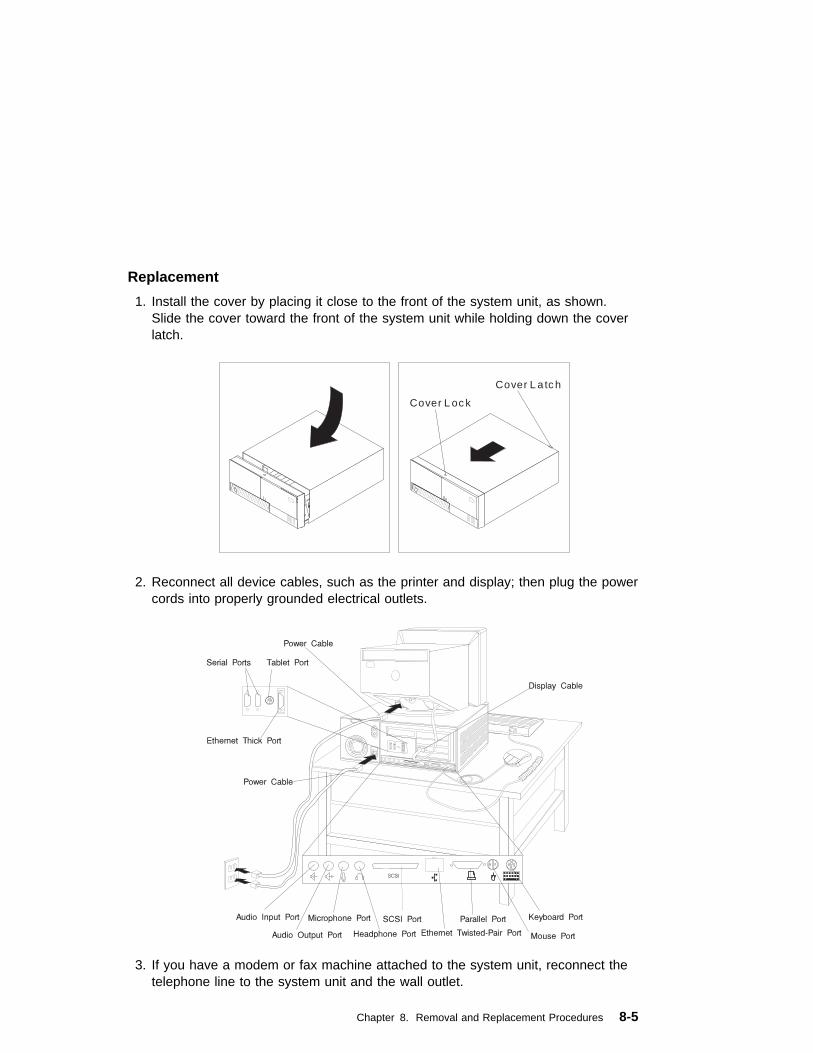
Replacement
1. Install the cover by placing it close to the front of the system unit, as shown.Slide the cover toward the front of the system unit while holding down the coverlatch.
Cover L ock
Cover L atch
2. Reconnect all device cables, such as the printer and display; then plug the powercords into properly grounded electrical outlets.
3. If you have a modem or fax machine attached to the system unit, reconnect thetelephone line to the system unit and the wall outlet.
Chapter 8. Removal and Replacement Procedures 8-5

Power Supply
DANGER
Do not attempt to open the covers of the power supply. Power suppliesare not servicable and are to be replaced as a unit.
Removal
1. Unplug all power cords (cables) from electrical outlets.
2. If you have not already done so, remove the cover as described in “Cover” onpage 8-3.
3. Disconnect the power supply cables from the system board connectors and anyinstalled drives.
4. Remove the rear bezel from the system unit by releasing the three latches andswinging the bezel away from the right side of the system unit.
8-6 7043 43P Series Service Guide
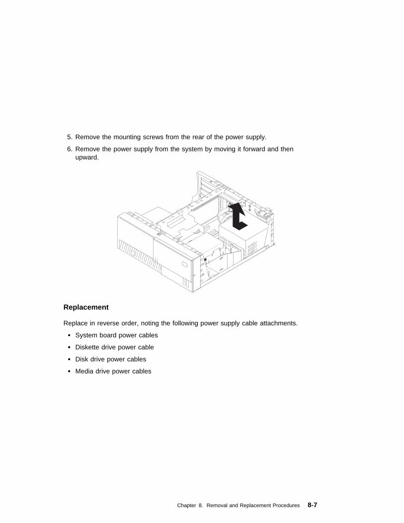
5. Remove the mounting screws from the rear of the power supply.
6. Remove the power supply from the system by moving it forward and thenupward.
Replacement
Replace in reverse order, noting the following power supply cable attachments.
� System board power cables
� Diskette drive power cable
� Disk drive power cables
� Media drive power cables
Chapter 8. Removal and Replacement Procedures 8-7

Cable Ties
After replacing the power supply, ensure you attach cable ties at the areasdesignated in the following diagrams:
P4 P3
100mm
P7P5
PowerSupply(Top View)
P6
25mm Max.
P8
PowerSupply(Top View)
8-8 7043 43P Series Service Guide
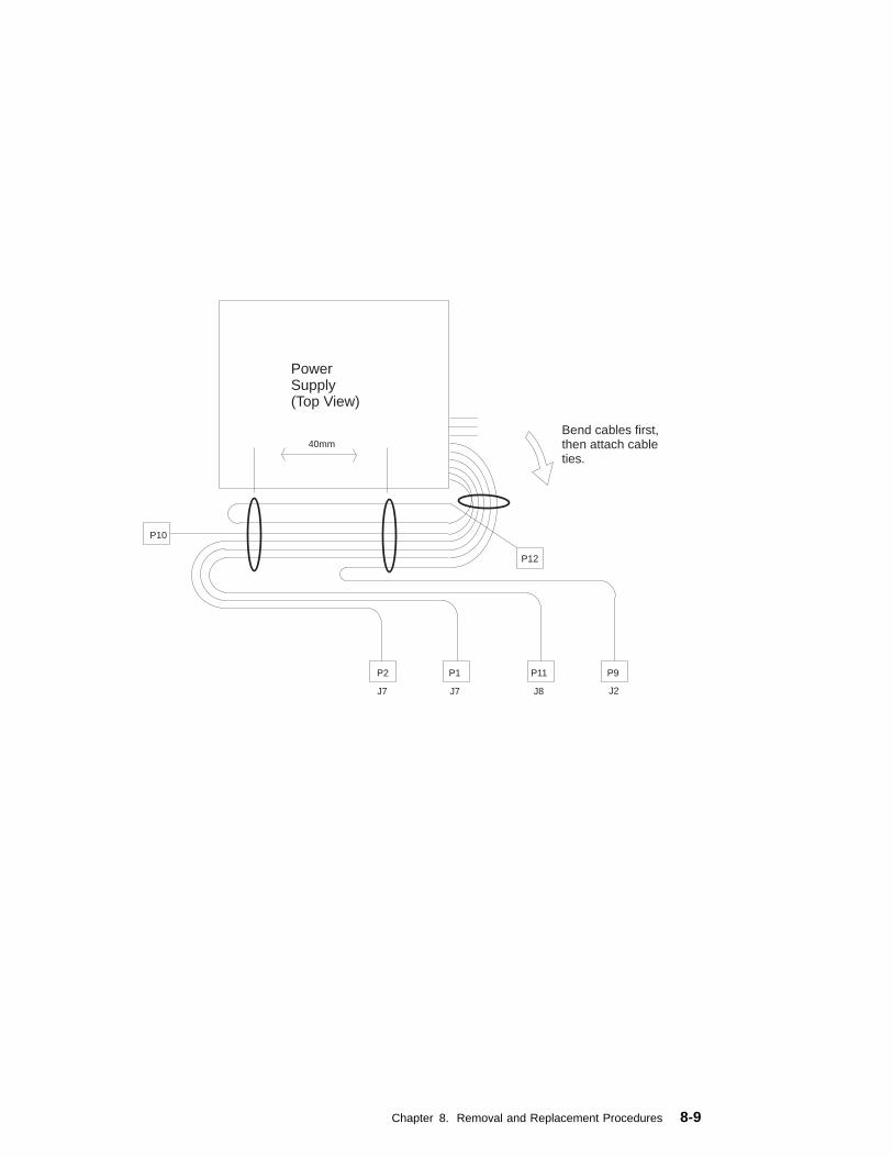
40mm
P12
Bend cables first,then attach cableties.
P11P1P2
P10
J7 J7 J8 J2
P9
PowerSupply(Top View)
Chapter 8. Removal and Replacement Procedures 8-9

Front Bezel and Power Switch
Removal
1. If you have not already done so, remove the covers as described in “Cover” onpage 8-3.
2. Do the removal procedure under “Fan and Speaker Assembly” on page 8-34.
3. Remove the media fan assembly and disconnect the media fan cable.
4. Snap off the media drive bracket attachment pin located at the left rear corner ofthe media drive bracket.
5. Remove the screw which secures the media drive bracket to the side of thechassis, then slide the media drive bracket assembly to the rear of the systemunit.
8-10 7043 43P Series Service Guide

6. All of the latches attaching the front bezel to the chassis are now accessible justinside the front of the system unit. Release these latches and pull the front bezelaway from the chassis.
7. To remove the power switch, remove the two screws which secure it to thechassis, then disconnect the power switch cable from the system board.
Replacement
1. Connect the power switch cable to the system board.
2. Fasten the power switch to the chassis with the two mounting screws.
3. Slide the front bezel onto the front of the chassis until the latches are securelymounted.
4. Slide the media drive bracket assembly towards the front of the chassis and intoposition.
5. Secure the media drive bracket assembly to the side of the chassis with themounting screw.
6. Connect the media fan cable to the system board.
7. Install the media fan assembly.
8. Install the front fan and speaker assembly as described on “Fan and SpeakerAssembly” on page 8-34
9. Replace the system unit covers as described in “Cover” on page 8-3.
Chapter 8. Removal and Replacement Procedures 8-11

Media Fan
Removal
1. If you have not already done so, remove the covers as described in “Cover” onpage 8-3.
2. Disconnect the media fan power cable.
3. Loosen the three screws which secure the media fan assembly to the side of themedia drive bracket.
4. Remove the media fan assembly.
Replacement
1. Place the media fan assembly into position.
2. Secure the media fan assembly to the side of the media drive bracket with thethree screws removed earlier.
3. Connect the media fan power cable to the system board.
8-12 7043 43P Series Service Guide

Internal Media Drives
Notes:
1. If you have not already done so, disconnect the power cord and remove thecovers as described in “Cover” on page 8-3.
2. If you are removing a CD-ROM drive refer to “Laser Safety Information” onpage xii.
Disk and media drives are installed in drive bays shown below.
Use the following SCSI cable routing table to ensure all cables are reattachedcorrectly.
Chapter 8. Removal and Replacement Procedures 8-13

Diskette Drive
Removal
1. Unplug the diskette power and signal cables from the back of the drive.
2. Remove the screws which secure the diskette drive to the media drive bracket.
Replacement: Replace in reverse order.
SCSI Cable SystemLocation
Cable Notes
Connector 1 System Board,J4
Between Connectors 1 and 2, route over power supply, notunder CD-ROM.
Connector 2 Bay 2, CD-ROM
Connector 3 Bay 3, LowerMedia
If empty, route extra cable through clamp above powersupply.
Connector 4 Bay 4, UppserDASD
Connector 5 Bay 5, LowerDASD
If empty, route extra cable through clamp above powersupply.
Connector 6 System Board,J33
8-14 7043 43P Series Service Guide
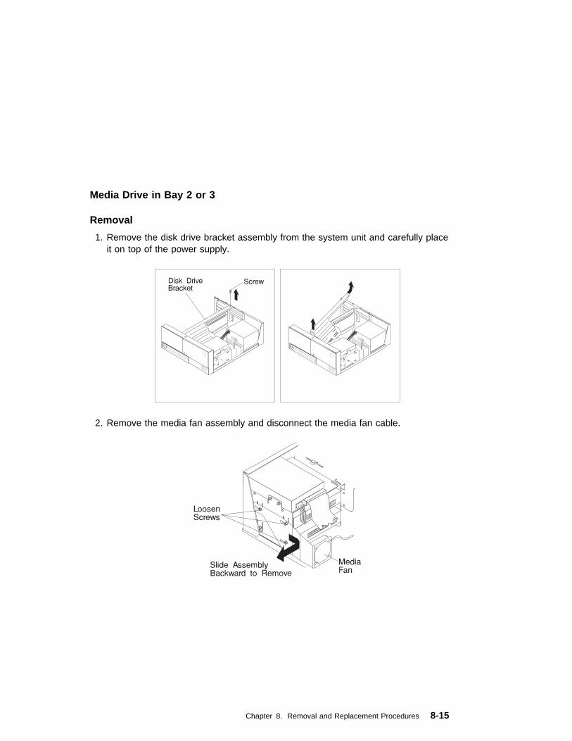
Media Drive in Bay 2 or 3
Removal
1. Remove the disk drive bracket assembly from the system unit and carefully placeit on top of the power supply.
2. Remove the media fan assembly and disconnect the media fan cable.
Chapter 8. Removal and Replacement Procedures 8-15
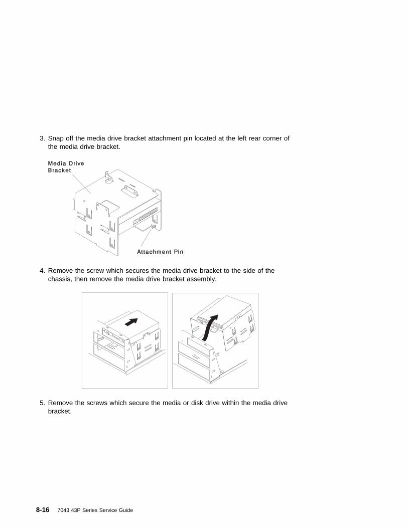
3. Snap off the media drive bracket attachment pin located at the left rear corner ofthe media drive bracket.
4. Remove the screw which secures the media drive bracket to the side of thechassis, then remove the media drive bracket assembly.
5. Remove the screws which secure the media or disk drive within the media drivebracket.
8-16 7043 43P Series Service Guide
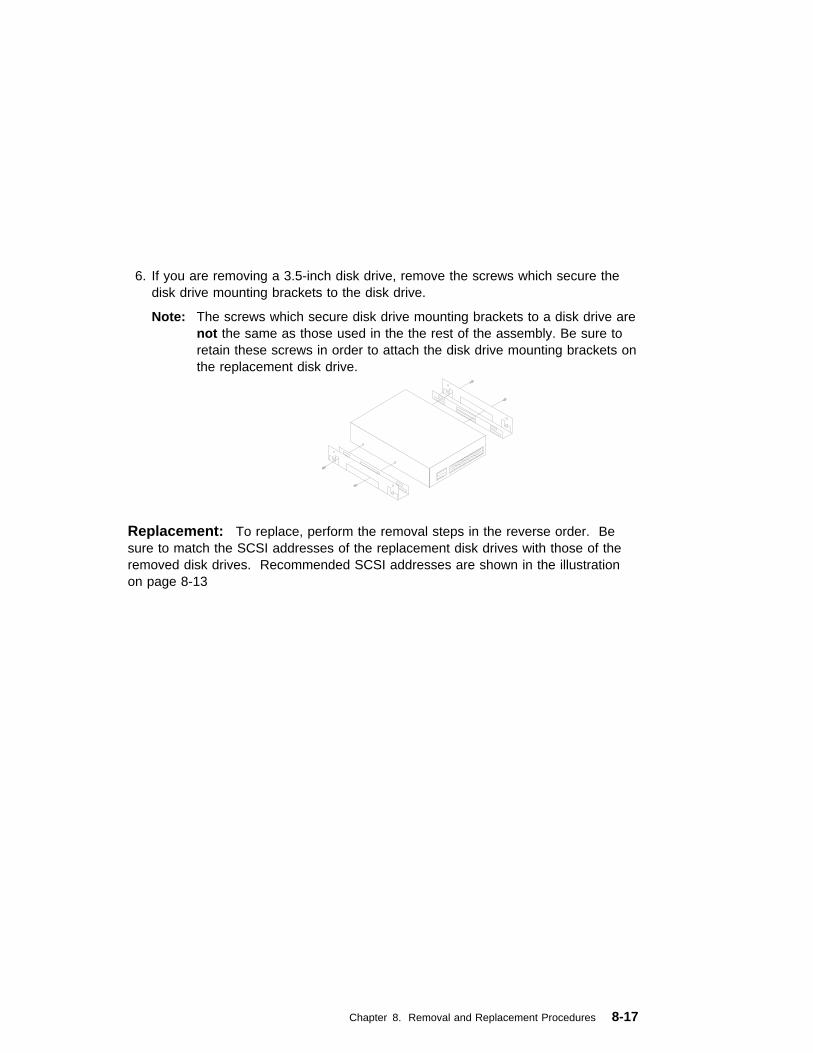
6. If you are removing a 3.5-inch disk drive, remove the screws which secure thedisk drive mounting brackets to the disk drive.
Note: The screws which secure disk drive mounting brackets to a disk drive arenot the same as those used in the the rest of the assembly. Be sure toretain these screws in order to attach the disk drive mounting brackets onthe replacement disk drive.
Replacement: To replace, perform the removal steps in the reverse order. Besure to match the SCSI addresses of the replacement disk drives with those of theremoved disk drives. Recommended SCSI addresses are shown in the illustrationon page 8-13
Chapter 8. Removal and Replacement Procedures 8-17

Media Drive in Bay 4 or 5
Removal
1. Remove the disk drive bracket assembly from the system unit.
2. Unplug the power and signal cables from the back of the disk drive or drives.
3. Remove the screws which secure the disk drive to the disk drive bracket.
Replacement: To replace, perform the removal steps in the reverse order. Besure to match the SCSI addresses of the replacement disk drives with those of theremoved disk drives. Recommended SCSI addresses are shown in the illustrationon page 8-13
8-18 7043 43P Series Service Guide

Adapter
Removal
1. If you have not already done so, remove the covers as described in “Cover” onpage 8-3.
2. Note the location of the adapter you are removing.
3. Remove the expansion-slot screw for the adapter; then grasp the adapter andpull it free from the socket.
Adapter
Riser
4. If you are not replacing the adapter in this slot, install an expansion-slot coverinto the empty expansion slot.
Expansion-SlotCover
Screw
Screw
Replacement
Replace in reverse order.
Chapter 8. Removal and Replacement Procedures 8-19

Memory Modules
Removal
1. Locate the memory-module connectors.
To locate the six memory-module slots in the Model 140, use the following figure.
To locate the four memory-module slots in the Model 150, use the followingfigure.
Memory-ModuleConnectors
1234
8-20 7043 43P Series Service Guide

The following figure shows the location of the eight memory-module slots in theModel 240.
2. Remove any adapters that are blocking the memory-module connectors (see“Adapter” on page 8-19)
3. Remove the memory module by first pushing out the locking tabs, then carefullypulling upward on the memory module.
Chapter 8. Removal and Replacement Procedures 8-21
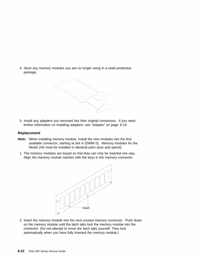
4. Store any memory modules you are no longer using in a static-protectivepackage.
5. Install any adapters you removed into their original connectors. If you needfurther information on installing adapters, see “Adapter” on page 8-19
Replacement
Note: When installing memory module, install the new modules into the firstavailable connector, starting at slot A (DIMM 0). Memory modules for theModel 240 must be installed in identical pairs (size and speed).
1. The memory modules are keyed so that they can only be inserted one way.Align the memory module notches with the keys in the memory connector.
2. Insert the memory module into the next unused memory connector. Push downon the memory module until the latch tabs lock the memory module into theconnector. (Do not attempt to move the latch tabs yourself. They lockautomatically when you have fully inserted the memory module.)
8-22 7043 43P Series Service Guide

Attention: Inserting the memory module at an angle may cause damage.
3. Inspect each memory module and ensure the gold connector is fully inserted inthe socket.
4. Reinstall any adapters you removed into their original connectors. (If you needfurther information for installing adapters, see “Adapter” on page 8-19).
Chapter 8. Removal and Replacement Procedures 8-23
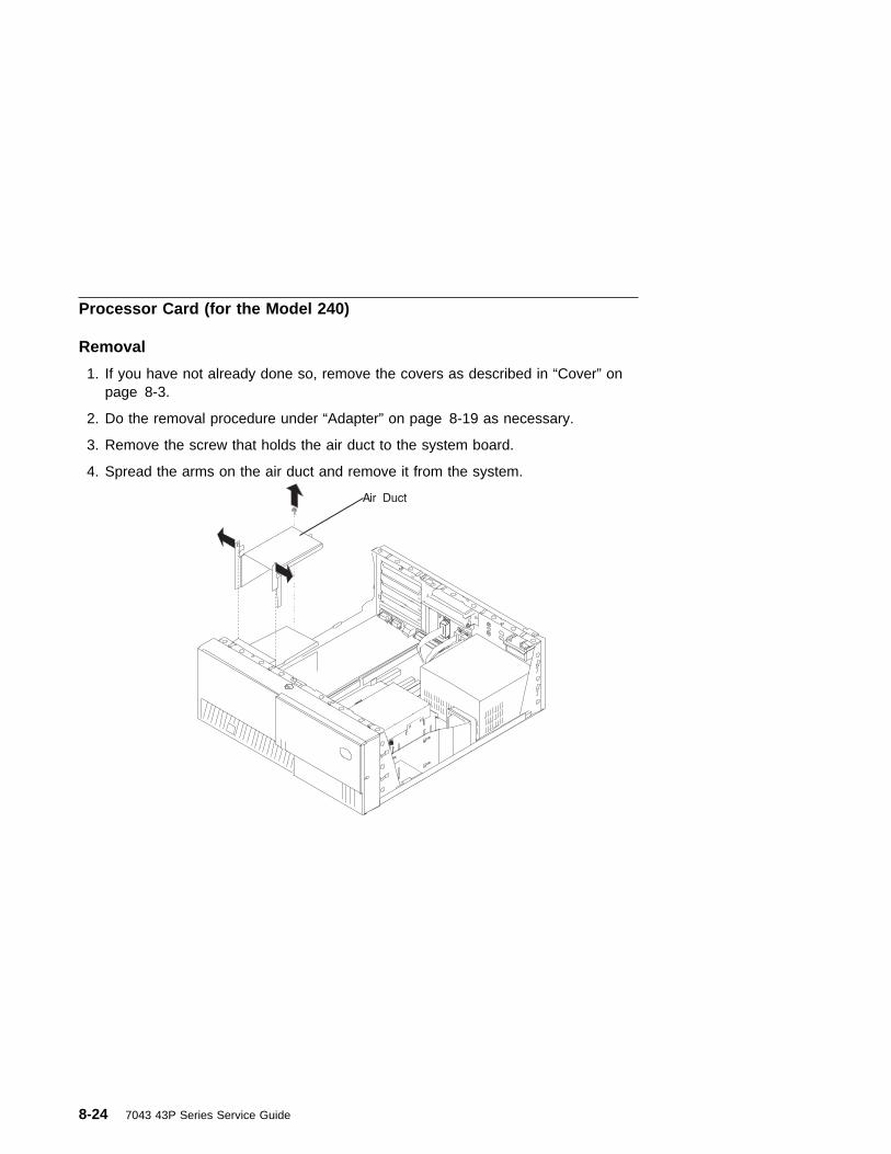
Processor Card (for the Model 240)
Removal
1. If you have not already done so, remove the covers as described in “Cover” onpage 8-3.
2. Do the removal procedure under “Adapter” on page 8-19 as necessary.
3. Remove the screw that holds the air duct to the system board.
4. Spread the arms on the air duct and remove it from the system.
8-24 7043 43P Series Service Guide

5. Push down the latches on the processor card connector to release the processorcard, and lift the card straight up and out of the system unit.
Replacement
Replace in reverse order.
Note: If more than one processor card is installed, both must be of the same speedand type.
Notes:
1. Do not push on the heatsink while installing or removing a processor card. Thiscould damage the processor.
2. Make sure to push down on the processor card until the latch tabs lock theprocessor card in place.
Chapter 8. Removal and Replacement Procedures 8-25

L2 Cache Card (for Model 140 Only)
Removal
1. Remove the disk drive bracket assembly from the system unit and carefully placeit on top of the power supply.
8-26 7043 43P Series Service Guide

2. Locate the L2 cache connector on the system board.
3. Gently pull upward on the L2 cache card, remove it from the system unit, andstore it in a safe place.
Replacement
Replace in the reverse order.
Chapter 8. Removal and Replacement Procedures 8-27

System Board
Removal
1. If you have not already done so, remove the covers as described in “Cover” onpage 8-3.
2. Do the removal procedure under “Adapter” on page 8-19.
3. Do the removal procedure under “Riser Card” on page 8-31.
4. Disconnect all cables from the system board.
5. Do the removal procedure under “Memory Modules” on page 8-20.
6. Do the removal procedure under “Processor Card (for the Model 240)” onpage 8-24.
7. Remove the screws from the system board.
8. Lift the system board out of the system unit.
8-28 7043 43P Series Service Guide
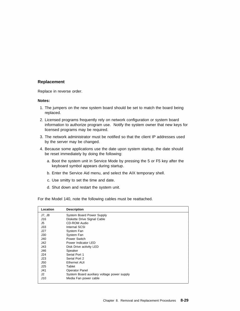
Replacement
Replace in reverse order.
Notes:
1. The jumpers on the new system board should be set to match the board beingreplaced.
2. Licensed programs frequently rely on network configuration or system boardinformation to authorize program use. Notify the system owner that new keys forlicensed programs may be required.
3. The network administrator must be notified so that the client IP addresses usedby the server may be changed.
4. Because some applications use the date upon system startup, the date shouldbe reset immediately by doing the following:
a. Boot the system unit in Service Mode by pressing the 5 or F5 key after thekeyboard symbol appears during startup.
b. Enter the Service Aid menu, and select the AIX temporary shell.
c. Use smitty to set the time and date.
d. Shut down and restart the system unit.
For the Model 140, note the following cables must be reattached.
Location Description
J7, J8 System Board Power SupplyJ16 Diskette Drive Signal CableJ5 CD-ROM AudioJ33 Internal SCSIJ27 System FanJ30 System FanJ40 Power SwitchJ42 Power Indicator LEDJ43 Disk Drive activity LEDJ46 SpeakerJ24 Serial Port 1J23 Serial Port 2J50 Ethernet AUIJ25 TabletJ41 Operator PanelJ2 System Board auxiliary voltage power supplyJ10 Media Fan power cable
Chapter 8. Removal and Replacement Procedures 8-29

For the Model 150, note the following cables must be reattached.
For the Model 240, note the following cables must be reattached.
Location Description
J7, J8 System Board Power SupplyJ16 Diskette Drive Signal CableJ5, J6 CD-ROM AudioJ33, J4 Internal SCSIJ27 System FanJ30 System FanJ40 Power SwitchJ42 Power Indicator LEDJ43 Disk Drive activity LEDJ46 SpeakerJ24 Serial Port 1J23 Serial Port 2J50 Ethernet AUIJ25 TabletJ41 Operator PanelJ2 System Board auxiliary voltage power supplyJ10 Media Fan power cable
Location Description
J27, J30,J33
System Board Power Supply
J26 Diskette Drive Signal CableJ15 CD-ROM AudioJ38, J10 Internal SCSI (16-bit)J31 Power SwitchJ44 Power Indicator LEDJ44 Disk Drive activity LEDJ41 SpeakerJ14 Serial Port 1J13 Serial Port 2J34 Ethernet AUIJ7 Tablet (on riser card)J5 Operator panel (on riser card)J42, J43 Front fanJ40 Media fan
8-30 7043 43P Series Service Guide

Riser Card
Removal
1. If you have not already done so, remove the covers as described in “Cover” onpage 8-3.
2. Remove all adapters; see “Adapter” on page 8-19.
3. Remove the drive bracket assembly and carefully lay it on the power supply.
4. Disconnect all cables attached to the riser card.
Chapter 8. Removal and Replacement Procedures 8-31

5. Pull the riser card straight up and out of the system unit. (The Model 240 isshown in the following illustration.)
Replacement
Replace in reverse order.
8-32 7043 43P Series Service Guide

I/O Panel
Removal
1. If you have not already done so, remove the covers as described in “Cover” onpage 8-3.
2. Disconnect the following cables from the system board:
� Serial Port 1
� Serial Port 2
� Tablet Port (2 connectors in some Model 140 systems)
� Ethernet AUI
3. Remove the screw securing the I/O panel to the rear of the chassis.
Replacement
Replace in the reverse order.
If the replacement I/O panel has a second connector on the tablet cable, refer to“System Board Locations (for Model 140)” on page 1-6 for the connector locations.
Chapter 8. Removal and Replacement Procedures 8-33

Fan and Speaker Assembly
Removal
1. Do the cover removal procedure in “Cover” on page 8-3.
2. For the Model 240:
� Remove the screw that holds the air duct to the system board.
� Spread the arms on the air duct enough to disengage them from themounting pins and remove it from the system unit.
3. Do the removal procedure under “Adapter” on page 8-19 if any installedadapters are long enough to interfere with the fan and speaker assembly.
8-34 7043 43P Series Service Guide

4. For the Model 240, do the procedure in “Processor Card (for the Model 240)” onpage 8-24.
5. Remove the drive bracket assembly and carefully lay it on top of the powersupply.
6. Disconnect the fan and speaker assembly cables from the system board.
7. Starting with the latch on the right side of the fan and speaker assembly, pressthe latches to release the fan and speaker assembly and lift it up and out of thesystem unit.
Replacement
Replace in reverse order.
Chapter 8. Removal and Replacement Procedures 8-35
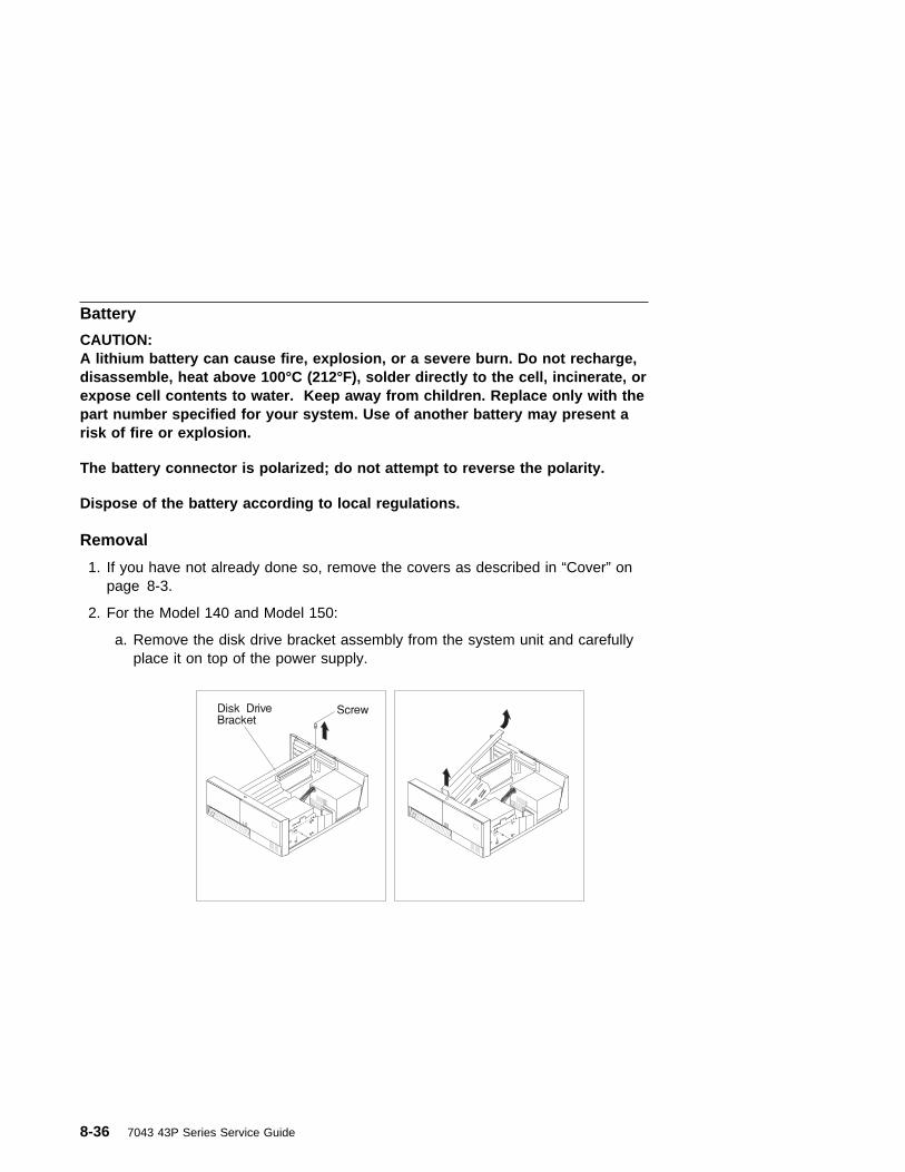
Battery
CAUTION:A lithium battery can cause fire, explosion, or a severe burn. Do not recharge,disassemble, heat above 100°C (212°F), solder directly to the cell, incinerate, orexpose cell contents to water. Keep away from children. Replace only with thepart number specified for your system. Use of another battery may present arisk of fire or explosion.
The battery connector is polarized; do not attempt to reverse the polarity.
Dispose of the battery according to local regulations.
Removal
1. If you have not already done so, remove the covers as described in “Cover” onpage 8-3.
2. For the Model 140 and Model 150:
a. Remove the disk drive bracket assembly from the system unit and carefullyplace it on top of the power supply.
8-36 7043 43P Series Service Guide

b. The following figure shows the location of the battery in the Model 140 andModel 150.
c. Remove the battery as shown.
3. For the Model 240.
Chapter 8. Removal and Replacement Procedures 8-37
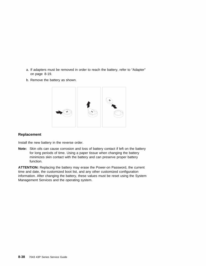
a. If adapters must be removed in order to reach the battery, refer to “Adapter”on page 8-19.
b. Remove the battery as shown.
Replacement
Install the new battery in the reverse order.
Note: Skin oils can cause corrosion and loss of battery contact if left on the batteryfor long periods of time. Using a paper tissue when changing the batteryminimizes skin contact with the battery and can preserve proper batteryfunction.
ATTENTION: Replacing the battery may erase the Power-on Password, the currenttime and date, the customized boot list, and any other customized configurationinformation. After changing the battery, these values must be reset using the SystemManagement Services and the operating system.
8-38 7043 43P Series Service Guide

Chapter 9. Parts Information
Chapter 9. Parts Information 9-1

System Unit
8
9
7
5
3
6
10
14
1215
13
11
12
21
23
28
26
2524
27
2930
16
17
18
20
19
1
2
4
22
9-2 7043 43P Series Service Guide

IndexNumber
Model140
Model150
Model240
UnitsPerAssy
Description
1 11H6764 11H6764 11H6764 1 Power Button2 33G3907 33G3907 33G3907 14 Screw3 73H0438 73H0438 73H0438 1 Power Switch Assembly4 73H0437 73H0437 73H0437 1 Power-On LED and Cable
73H0436 73H0436 73H0436 1 Disk Activity LED and Cable5 94H0550 08L0033 94H0550 1 Logo6 88G2411 n/a 88G2411 1 Operator Panel Circuit Assembly7 07L6776 07L9108 07L6776 1 Front Bezel, Keylock, Keys8 40H7584 40H7584 93H1820 1 Fan and Speaker Assembly9 93H1819 93H1819 93H1819 1 Operator Panel Bracket10 n/a n/a 11H9747 1 Air flow baffle11 Note 1 Note 1 Note 1 1 Disk Drive Bracket12 27F4212 27F4212 27F4212 25-48 Screw, M35 (Disk Drive)13 Note 2 Note 2 Note 2 1-2 Disk Drive14 12H0649 07L9112 12H0649 1 EMC Shield15 Note 1 07L9094;
Note 1Note 1 1 Top Cover Assembly
16 88G2216 88G2216 88G2216 1 3.5-inch Disk Drive MountingBrackets
17 93F2361 76H4091 93F2361 1 Diskette Drive18 Note 1 Note 1 Note 1 1 Media Drive Bracket19 93H1817 93H1817 93H1817 1 Media Fan Assembly20 40H5180 n/a n/a 1 Fansink for 166MHz, 200MHz, and
233Mhz CPUs93H9648 93H9648 n/a 1 Fansink for 332MHz and 375MHz
CPUs only21 Note 2 Note 2 Note 2 1-2 Disk Drives or removable-media
drives22 93H5982 07L9085 73H3765 1 Cable and Bracket Assembly23 06H8488 07L9084 06H8488 1 Rear Panel24 Note 1 Note 1 Note 1 1 PCI/ISA Bulkhead25 06H6706 07L9097 06H6706 1 Top Cover Latch26 Note 1 Note 1 Note 1 1 Chassis27 40H7563 n/a 40H7563 1 Power Supply without Power Factor
Correction40H7566 40H7566 40H7566 1 Power Supply with Power Factor
Correction (Japan)28 Note 1 07L9096;
Note 1Note 1 1 Bottom Panel
29 93H4574 93H4574 93H4574 5 Cable Tie (Adhesive Base)30 Note 1 Note 1 Note 1 1 4-slot EMC shieldNote:
1. This part is included in the Cover Assembly FRU 07L6923 for the Model 140, Cover AssemblyFRU 07L9078 for the Model 150, or Cover Assembly FRU 93H7799 for the Model 240.
2. See the documentation for the specific device, or refer to the Adapters, Devices, and CableInformation for Multiple Bus Systems.
Chapter 9. Parts Information 9-3

System Board, Cables, and Accessories
9-4 7043 43P Series Service Guide

Note: Model 240 memory modules must be installed in groups of matched pairs.
IndexNumber
FRUNumber
Units Per Assy Description
1 93H7142 1 System Board 166-MHz (Model 140)93H7143 1 System Board 200-MHz (Model 140)93H6023 1 System Board 233-MHz (Model 140)93H9334 1 System Board 332-MHz (Model 140)07L8446 1 System Board (Model 150)11H7516 1 System Board (Model 240)
2 27F4212 6 Screw3 39H8697 1 Hex Standoff4 11H7517 1 166MHz Processor and Cache Card (Model 240
Only)93H5163 1 233MHz Processor and Cache Card (Model 240
Only)75H5462 1 512KB L2 Cache Card (Model 140 Only)75H5463 1 1MB L2 Cache Card (Model 140 Only)
5 42H2772 1-6 (Model 140),2-8 (Model 240)
16MB DIMM
42H2773 1-6 (Model 140),2-8 (Model 240)
32MB DIMM
42H2774 1-6 (Model 140)2-8 (Model 240)
64MB DIMM
19L1808 1-4 (Model 150) 64MB DIMM (Model 150)93H6823 1-6 (Model 140) 128MB DIMM (Model 140)19L1809 1-4 (Model 150) 128MB DIMM (Model 150)93H6822 2-8 (Model 240) 128MB DIMM (Model 240)29L3302 1-4 (Model 150) 256MB DIMM (Model 150)
6 93H1821 1 Diskette Cable Assembly7 92F2565 1 Interposer8 73H0435 1 SCSI Cable Assembly (Model 140 and Model
150)40H7572 1 SCSI Cable Assembly (Model 240)
9 93H6151 1 Ultra SCSI Cable Assembly (Optional)10 73H4532 1 Riser Card (Model 140)
08L1417 1 Riser Card (Model 150)73H3712 1 Riser Card (Model 240)
11 12H0619 1 Vertical Stand (Model 140 and Model 240)07L9115 1 Vertical Stand (Model 150)
12 40H6328 2 9-pin to 25-pin Serial Port Converters13 11H2168 1 Display Cable Toroid Kit14 15F8409 1 Battery15 65G8850 1 CD-ROM drive audio cable
Chapter 9. Parts Information 9-5

Keyboard and Mouse
9-6 7043 43P Series Service Guide
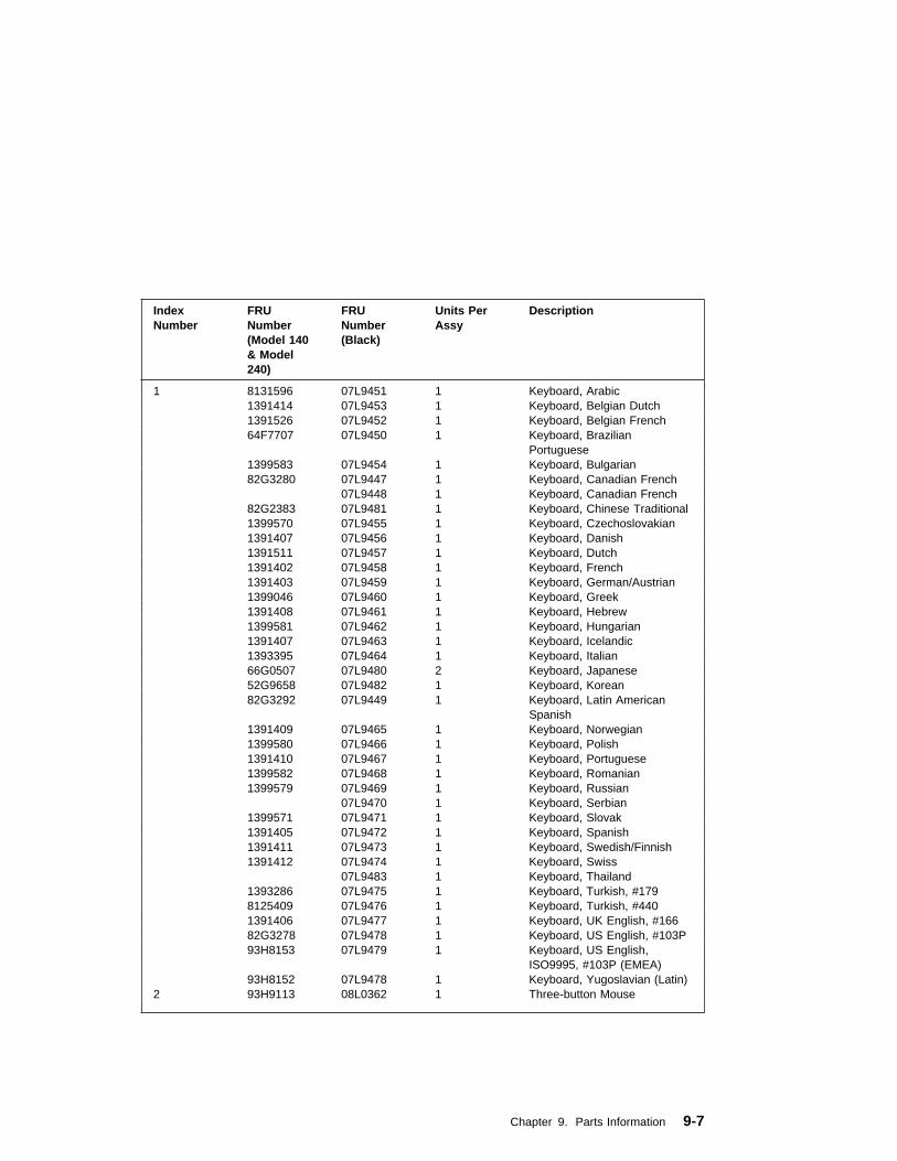
IndexNumber
FRUNumber(Model 140& Model240)
FRUNumber(Black)
Units PerAssy
Description
1 8131596 07L9451 1 Keyboard, Arabic 1391414 07L9453 1 Keyboard, Belgian Dutch 1391526 07L9452 1 Keyboard, Belgian French 64F7707 07L9450 1 Keyboard, Brazilian
Portuguese 1399583 07L9454 1 Keyboard, Bulgarian 82G3280 07L9447 1 Keyboard, Canadian French 07L9448 1 Keyboard, Canadian French 82G2383 07L9481 1 Keyboard, Chinese Traditional 1399570 07L9455 1 Keyboard, Czechoslovakian 1391407 07L9456 1 Keyboard, Danish 1391511 07L9457 1 Keyboard, Dutch 1391402 07L9458 1 Keyboard, French 1391403 07L9459 1 Keyboard, German/Austrian 1399046 07L9460 1 Keyboard, Greek 1391408 07L9461 1 Keyboard, Hebrew 1399581 07L9462 1 Keyboard, Hungarian 1391407 07L9463 1 Keyboard, Icelandic 1393395 07L9464 1 Keyboard, Italian 66G0507 07L9480 2 Keyboard, Japanese 52G9658 07L9482 1 Keyboard, Korean 82G3292 07L9449 1 Keyboard, Latin American
Spanish 1391409 07L9465 1 Keyboard, Norwegian 1399580 07L9466 1 Keyboard, Polish 1391410 07L9467 1 Keyboard, Portuguese 1399582 07L9468 1 Keyboard, Romanian 1399579 07L9469 1 Keyboard, Russian 07L9470 1 Keyboard, Serbian 1399571 07L9471 1 Keyboard, Slovak 1391405 07L9472 1 Keyboard, Spanish 1391411 07L9473 1 Keyboard, Swedish/Finnish 1391412 07L9474 1 Keyboard, Swiss 07L9483 1 Keyboard, Thailand 1393286 07L9475 1 Keyboard, Turkish, #179 8125409 07L9476 1 Keyboard, Turkish, #440 1391406 07L9477 1 Keyboard, UK English, #166 82G3278 07L9478 1 Keyboard, US English, #103P 93H8153 07L9479 1 Keyboard, US English,
ISO9995, #103P (EMEA) 93H8152 07L9478 1 Keyboard, Yugoslavian (Latin)2 93H9113 08L0362 1 Three-button Mouse
Chapter 9. Parts Information 9-7
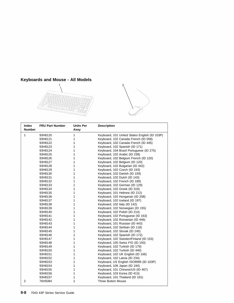
Keyboards and Mouse - All Models
IndexNumber
FRU Part Number Units PerAssy
Description
1 93H8120 1 Keyboard, 101 United States English (ID 103P) 93H8121 1 Keyboard, 102 Canada French (ID 058) 93H8122 1 Keyboard, 102 Canada French (ID 445) 93H8123 1 Keyboard, 102 Spanish (ID 171) 93H8124 1 Keyboard, 104 Brazil Portuguese (ID 275) 93H8125 1 Keyboard, 102 Arabic (ID 238) 93H8126 1 Keyboard, 102 Belgium French (ID 120) 93H8127 1 Keyboard, 102 Belgium (ID 120) 93H8128 1 Keyboard, 102 Bulgarian (ID 442) 93H8129 1 Keyboard, 102 Czech (ID 243) 93H8130 1 Keyboard, 102 Danish (ID 159) 93H8131 1 Keyboard, 102 Dutch (ID 143) 93H8132 1 Keyboard, 102 French (ID 189) 93H8133 1 Keyboard, 102 German (ID 129) 93H8134 1 Keyboard, 102 Greek (ID 319) 93H8135 1 Keyboard, 101 Hebrew (ID 212) 93H8136 1 Keyboard, 102 Hungarian (ID 208) 93H8137 1 Keyboard, 102 Iceland (ID 197) 93H8138 1 Keyboard, 102 Italy (ID 142) 93H8139 1 Keyboard, 102 Norwegian (ID 155) 93H8140 1 Keyboard, 102 Polish (ID 214) 93H8141 1 Keyboard, 102 Portuguese (ID 163) 93H8142 1 Keyboard, 102 Romanian (ID 446) 93H8143 1 Keyboard, 101 Russian (ID 443) 93H8144 1 Keyboard, 102 Serbian (ID 118) 93H8145 1 Keyboard, 102 Slovak (ID 245) 93H8146 1 Keyboard, 102 Spanish (ID 172) 93H8147 1 Keyboard, 102 Sweden/Finland (ID 153) 93H8148 1 Keyboard, 105 Swiss F/G (ID 150) 93H8149 1 Keyboard, 102 Turkish (ID 179) 93H8150 1 Keyboard, 102 Turkish (ID 440) 93H8151 1 Keyboard, 102 UK English (ID 166) 93H8152 1 Keyboard, 102 Latvia (ID 234) 93H8153 1 Keyboard, US English ISO9995 (ID 103P) 93H8154 1 Keyboard, 106 Japan (ID 194) 93H8155 1 Keyboard, 101 Chinese/US (ID 467) 93H8156 1 Keyboard, 103 Korea (ID 413) 93H8157 1 Keyboard, 101 Thailand (ID 191)2 76H5084 1 Three Button Mouse
9-8 7043 43P Series Service Guide

Power Cables
1 2 3 4
5 6 7
8 9 10 11
Index Part Number Country
1 1838574 Bahamas, Barbados, Bolivia, Brazil, Canada, Costa Rica,Dominican Republic, El Salvador, Ecuador, Guatemala, Guyana,Haiti, Honduras, Jamaica, Japan, Netherlands Antilles, Panama,Peru, Philippines, Taiwan, Thailand, Trinidad, Tobago, U.S.A.(except Chicago), Venezuela
2 6952300 Bahamas, Barbados, Bermuda, Bolivia, Brazil, Canada, CaymanIslands, Colombia, Costa Rica, Dominican Republic, Ecuador, ElSalvador, Guatemala, Guyana, Haiti, Honduras, Jamaica, Japan,Korea (South), Mexico, Netherlands Antilles, Nicaragua, Panama,Peru, Philippines, Puerto Rico, Saudi Arabia, Suriname, Trinidad,Taiwan, U.S.A. (except Chicago), Venezuela
2 62X1045 Chicago, U.S.A., stackable
3 13F9940 Argentina, Australia, New Zealand
4 13F9979 Abu Dhabi, Austria, Belgium, Bulgaria, Botswana, Egypt, Finland,France, Germany, Greece, Iceland, Indonesia, Korea (South),Lebanon, Luxembourg, Macau, Netherlands, Norway, Poland,Portugal, Romania, Saudi Arabia, Spain, Sudan, Sweden, Turkey,Yugoslavia
5 13F9997 Denmark
6 14F0015 Bangladesh, Burma, Pakistan, South Africa, Sri Lanka
Chapter 9. Parts Information 9-9

Index Part Number Country
7 14F0033 Bahrain, Bermuda, Brunei, Channel Islands, Cyprus, Ghana,Hong Kong, India, Iraq, Ireland, Jordan, Kenya, Kuwait, Malawi,Malaysia, Nigeria, Oman, People's Republic of China, Qatar,Sierra Leone, Singapore, Tanzania, Uganda, United ArabEmirates (Dubai), United Kingdom, Zambia
8 14F0051 Liechtenstein, Switzerland
9 14F0069 Chile, Ethiopia, Italy
10 14F0087 Israel
11 6952291 Paraguay, Colombia, Uruguay
9-10 7043 43P Series Service Guide

Appendix A. Interpreting Firmware Error Codes
The error code is an 8-character (4-byte) hexadecimal code produced by firmware toidentify the potential failing function or FRU in a system. It consists of 5 source codecharacters and 3 reason code characters. Individual characters within the error codehave specific field definitions, as defined in the following tables. Table A-1 andTable A-2.
Table A-1. Service Reference Code Field Layout
Source Code Reason Code
Byte 0 Byte 1 Byte 2 Byte 3
S1 S2 S3 S4 S5 R1 R2 R3
Table A-2 (Page 1 of 2). Service Reference Code Field Descriptions
Field Description
S1
Maintenance Package Source that produced the error code.
0 Reserved
1 Reserved
2 POST, Firmware
3 BIST
4 Service Processor, base system controller, etc.
5 Reserved
8 Product specific service guide, MAPs
9 Reserved
A-F Reserved
S2 Base class
S3-S4 Sub-class
S5 Unique version of the device/FRU type for a particular product.
R1
Device/FRU unique failure reason codes.
1-7 Use in combination with R2, R3 for diagnostic test failure whenmaximum isolation was obtained.
8-9 Use in combination with R2, R3 for diagnostic test failure whenmaximum isolation was NOT obtained.
A Log analysis of POST error log
B Log analysis of machine check or checkstop error log
C Reserved
D Diagnostic detected missing resource
E-F Reserved
Appendix A. Interpreting Firmware Error Codes A-1

Table A-2 (Page 2 of 2). Service Reference Code Field Descriptions
Field Description
R2 - R3 Device/FRU unique failure reason codes.
Table A-3 (Page 1 of 3). Current PCI 2.1 Class Code Definition
PCI BaseClass(lowernibble) S2
PCISub-ClassS3 -S4
Description
0
Devices that were built before the class code field was defined.
00All currently implemented devices except VGA-compatibledevices.
01 VA-compatible devices
1
Mass storage controller
00 SCSI bus controller
01 IDE controller
02 Floppy disk controller
03 Intelligent Peripheral Interface (IPI) bus controller
04 Redundant Array of Independent Disk (RAID) controller
80 Other mass storage controller
2
Network controller
00 Ethernet controller
01 Token Ring controller
02 FDDI controller
03 ATM controller
80 Other network controller
3
Display controller
00 VGA-Compatible controller
01 Extended Graphics Array (XGA) controller
80 Other display controller
4
Multimedia device
00 Video device
01 Audio device
80 Other multimedia device
5
Memory controller
00 RAM
01 Flash
80 Other memory controller
A-2 7043 43P Series Service Guide

Table A-3 (Page 2 of 3). Current PCI 2.1 Class Code Definition
6
Bridge devices
00 Host bridge
01 ISA bridge
02 EISA bridge
03 MCA bridge
04 PCI-to-PCI bridge
05 PCMCIA bridge
06 NuBus bridge
07 Cardbus bridge
80 Other bridge device
7
Simple communication controllers
00 Serial controllers
01 Parallel port
80 Other communication controllers
8
Generic system peripherals
00 PIC
01 DMA controller
02 System timer
03 Real-Time Clock (RTC) controller
80 Other system peripherals
9
Input devices
00 Keyboard controller
01 Digitizer (pen)
02 Mouse controller
80 Other input controllers
A
Docking stations
00 Generic docking station
80 Other type of docking station
B
Processors
00 Reserved
01 Reserved
02 Reserved
10 Reserved
20 PowerPC
40 Co-processor
Appendix A. Interpreting Firmware Error Codes A-3
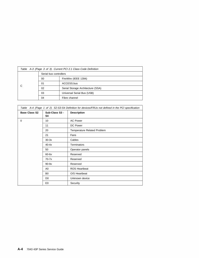
Table A-3 (Page 3 of 3). Current PCI 2.1 Class Code Definition
C
Serial bus controllers
00 FireWire (IEEE 1394)
01 ACCESS.bus
02 Serial Storage Architecture (SSA)
03 Universal Serial Bus (USB)
04 Fibre channel
Table A-4 (Page 1 of 2). S2-S3-S4 Definition for devices/FRUs not defined in the PCI specification
Base Class S2 Sub-Class S3 -S4
Description
0 10 AC Power
11 DC Power
20 Temperature Related Problem
21 Fans
30-3x Cables
40-4x Terminators
50 Operator panels
60-6x Reserved
70-7x Reserved
90-9x Reserved
A0 ROS Heartbeat
B0 O/S Heartbeat
D0 Unknown device
E0 Security
A-4 7043 43P Series Service Guide

Table A-4 (Page 2 of 2). S2-S3-S4 Definition for devices/FRUs not defined in the PCI specification
Base Class S2 Sub-Class S3 -S4
Description
1 A0 SCSI Drivers (generic)
B0 IDE Drives
C0 RAID Drives
D0 SSA Drives
E0 Tapes SCSI
E1 Tapes IDE
ED SCSI changer
EE Other SCSI device
EF Diskette drive
F0 CDROM SCSI
F1 CDROM IDE
F2 Read/Write optical SCSI
F3 Read/Write optical IDE
F4 - FF TBD media devices
5 A0 L2 Cache Controller including integrated SRAM
A1 L2 Cache SRAM
A8 NVRAM
A9 CMOS
AA Quartz/EEPROM
B0 - Bx Memory cards
Cyy Memory Dimms (Where C is S2, S3, or S4 and yyidentifies the memory size and type).
7 A0 I2C bus
8 A0 Power Management Functions
9 A0 - Ax Keyboards
B0 - Bx Mouse(s)
C0 - Cx Dials
D0 Tablet
D1 - Dx TBD input devices
B A0 Service processor
Appendix A. Interpreting Firmware Error Codes A-5

A-6 7043 43P Series Service Guide

Index
Aabout this book xvadapter removal 8-19AIX location codes 5-4audio ports 1-2
Bbattery
disposal, recycling xiiiboot list 6-1bus SRN to FRU Table 4-11
CCD-ROM eject button 1-1command line, open firmware 7-44cover installation 8-5cover lock 8-3
Ddevices, startup 7-9diskette eject button 1-1
Eemergency eject, CD-ROM 1-1error code to FRU index
Model 140 and Model 240 3-2Model 150 4-1
error codesfirmware A-1POST 3-2
Ethernet 1-2Ethernet port 1-2
Hhard disk drive in-use light 1-1headphone connector, CD-ROM 1-1headphone port 1-2
Iindex, error code to FRU 3-2installing
cover 8-5memory modules 8-22
Kkeyboard
port 1-2keyboards 9-8
Llaser safety information xiilocation codes - Model 150 5-1
AIX 5-4format 5-1physical 5-1
Mmaintenance analysis procedures
(MAPs) 2-1minimum configuration Map 2-21power MAP 2-15problem determination MAP 2-7quick entry MAP 2-2
media removal 8-3memory PD bits 4-13memory problem resolution map 2-12
Index X-1

microphone port 1-2minimum configuration Map 2-21
Oopen firmware command line 7-44operator panel display 1-1ordering
publications xv, xvi
Pparallel port 1-2part numbers
publications xviparts 9-8
keyboard 9-8PD bits 4-13physical location codes 5-1POST error codes 3-2power MAP 2-15power switch, location 1-1power-on light 1-1preface xvproblem determination MAP 2-7product disposal xiiipublications
ordering xv, xvi
Qquick entry MAP 2-2
Rrecycling xiiirelated publications xvreset button 1-1
S
SCSI port 1-2sequence, startup 7-9Start Up program 7-9starting system programs 7-1, 7-26status light, CD-ROM 1-1Sys Config program 7-4system programs 7-1
Start Up 7-9starting 7-1, 7-26Sys Config 7-4Utilities 7-11
Ttablet 1-2
Uunlocking cover lock 8-3Utilities program 7-11
Vvoltage-selection switch 1-2volume control, CD-ROM 1-1
X-2 7043 43P Series Service Guide

IBM
Part Number: 08L0664
Printed in the United States of Americaon recycled paper containing 10%recovered post-consumer fiber.
SA38-ð512-ð3
ð8Lð664