Embed Size (px)
Citation preview


SERVICE FACILITIES
WISCONSIN MOTORS, L.L.C. Distributors and Service Centers, located throughout the U.S. and foreign countries, have been carefully selected to insure complete and efficient repair and inspection services to owners of WISCONSIN MOTORS Engines. These service centers, equipped and staffed for complete engine repair, also stock engines parts to facilitate immediate delivery for the complete line of WISCONSIN MOTORS Engines. Order parts from the WISCONSIN MOTORS, L.L.C. Distributor or Service Center in your locality. Refer to the Yellow Pages of the Telephone Directory under ENGINES, or write to WISCONSIN MOTORS, L.L.C. for a free copy of a list of authorized Distributors and Service Centers. Do not order parts from WISCONSIN MOTORS, L.L.C. in Memphis, TN. The MODEL, SPECIFICATION and SERIAL NUMBER of your engine must be given when ordering parts. The MODEL and SPECIFICATION number are on the name plate. The SERIAL NUMBER is stamped either on the crankcase or the engine’s identification tag. Copy the MODEL, SPECIFICATION and SERIAL NUMBER in the spaces provided below so that it will be available when ordering parts.
MODEL SPECIFICATON SERIAL NUMBER To insure prompt and accurate service, the following information must also be given: 1. State EXACTLY the quantity of each part and part number. 2. State definitely whether parts are to be shipped by express, freight or parcel post. 3. State exact mailing address.

Wisconsin Motors, LLC

3

Manifold and Crankcas
ITEM
123456
789
1011121314151617
18192021222324
PART NO.AB111QD631PH22XD30YD6S1
* BA49AS1
BH155AQD635PE4XD14XK4PF143SA26SA58QD632PC435PE7PE81PD13XD14ARF1495FRJ173ABK72PE37XD52
DESCRIPTION QT¥
Cylinder head ............................................................................... 2Gasket, cylinder head .................................................................. 2Washer, 3/8" x 11/16". .............................................................. 34Screw, 3/8"-16 x 1-1/2" long (special hardness) ................... 34Spark plug, Champion No. D-16-J ............................................ 4Crankcase assembly (includes items 12-14, 16, 19; and oilfiller neck and screen, oil header tube, oil spray nozzlesand dipstick, and tube adapter for oil filler side of engine) .. 1Cover plate, crankcase bottom ................................................... 1Gasket, bottom cover plate ......................................................... 1Lock washer, 5/16" spring lock ............................................... 16Screw, 5/16"-18 thread x 5/8" long ......................................... 14Pipe plug, 1/2" square head, oil drain ...................................... 1Plug, for 5/8"-11 tap in face of case, upper left hand ............. 1Plug, 5/8" expansion, for camshaft oil hole ............................. 2Plug, 1-3/8" expansion ................................................................ 1Gasket, cylinder base ................................................................... 2Stud, cylinder block mounting ................................................ 12Lock washer, 1/2" spring lock ................................................. 10Washer, 1/2" external everlock for center stud in vee ........... 2Nut, 1/2"-20 thread ................................................................... 12Screw, 5/16-18" x 5/8". ............................................................... 2Adapter tube, dipstick (optional on starter side) .................... 1Dipstick, 6-1/4" long (optional on starter side) ....................... 1Engine support, cast iron ............................................................ 2Lock washer, 5/8" spring lock ................................................... 4Screw, 5/8"-11 x 1-3/4" long ...................................................... 4
* BA49AS1 is standard machining number. A dash number is added for anyspecial machining (located on marking pad).
** See page 14 for standard dipsitck and adapter
continued on page 4
-2-
WISCONSIN MODEL VG4D

3

Manifold and Crankcase (cont.)
ITEM
25
262728
29
303132333435363738
PART NO.
LD240LD240-1LD240CQB83QC.66PC615
PH79A
PD207XK1QC12AL57-1S1VE693-1WD101LJ161XD19XA33
DESCRIPTION QTY
Inlet and exhaust manifold (Vertical) ........................................ 1Manifold for power units ............................................................ 1Inlet and exhaust manifold (Horizontal)Insert, manifold gasket ................................................................ 6Gasket, manifold to cylinder block (replaces QC62) ............... 6Stud, manifold to cylinder block,(included with AA90AS8 cylinder block assy.) ....................... 4Washer, 7/16" x 13/16" x 1/8",manifold to cylinder block .......................................................... 4Nut, 7/16"-20 thread, manifold to cylinder block ................... 4Pipe plug, 1/8" square head ....................................................... 1Gasket, carburetor ........................................................................ 3Carburetor, Facet No. 11532 ........................................................ 1Choke control ................................................................................ 1Muffler, standard .......................................................................... 1Pipe nipple, 1-1/2" x 2" long ....................................................... 1Screw, 5/16"-18 x 1-1/4" long ..................................................... 2Screw, 1/4"-20 x 3/8" long,for tap in cylinder block (R.H. side) ........................................... 1
-4-
Rev 10 / 90WISCONSIN MODEL VG4D

15
.3
5
~4
1
o 6

Crankshaft, Piston and Connecting Rod
ITEM
123456789
101112
131415
16171819
PART NO.
BG193A6S2PH269QD636BQD636AQF67CPE5AXD29CCA69CS1ME98
GA35A1GA35CPL49RK173DA66BS1
HA135SHA135S1HA135S2HA135S10HA135S20HG131CPB146-1S1PD247DB183DISP
DB183D1SP10DB183DISP20DB183D1SP30
DESCRIPTION QT¥
Main bearing plate assembly (includes items 2 & 11) ............. 1Main bearing oil seal, take-off end ............................................. 1Gasket, bearing plate, .006" thick ............................................... 3Gasket, bearing plate, .003" thick ............................................... 3Shim, bearing plate, .014" thick .................................................. 1Lock washer, 3/8" spring lock, main bearing plate ................ 6Screw, 3/8"-16 x 1-1/4" long main bearing plate .................... 6Crankshaft assembly (includes items 9, 12-14) ........................ 1Main bearing (includes items 10 - 11) ........................................ 2Cone ................................................................................................1Cup .................................................................................................1Crankshaft gear, standard ........................................................... 1Crankshaft gear, hardened .......................................................... 1Woodruff key, No. 15 .................................................................. 1Oil sling ..........................................................................................1Connecting rod, shell bearing type (includes items 16-18)(replaces DA66AS1) (shell bearings not furnished) ................ 4Shell bearing, 2 halves ................................................................. 4Shell bearing, .001". ...................................................................... 1Shell bearing, .002". ...................................................................... 1Shell bearing, .010". ...................................................................... 1Shell bearing, .020". ...................................................................... 1Piston pin bushing ........................................................................ 4Connecting rod bolt assembly (includes item 18) ................... 8Nut, 3/8"-24 thread, special ........................................................ 8Piston, standard (includes items 20 & 21)(replaces DB183D) ........................................................................ 4Piston, 0.010" O/S ......................................................................... 4Piston, 0.020" O/S ......................................................................... 4Piston, 0.030" O/S ......................................................................... 4
Not serviced separately.
CA69CS1 is standard machining number. A dash number is added for anyspecial machining (located on marking pad).
continued on page 8
-6-
WISCONSIN MODEL VG4D

22
2O 21 13
2524
16
15 17 18
-1
-7

Crankshaft, Piston and Connecting Rod (cont.)
ITEM
202122
23
2425262728
PART NO.
DE59PK37ADR15DDR15DS10DR15DS20DR15DS30DR44DR44S10DR44S20DR44S30N100A
N100B14
N120N120DN120-1N120D1PL24PA334U226PD157PE65-1
DESCRIPTION QTY
Piston pin, standard; also available in .005" & .010" O/S ....... 4Retaining ring (replaces PK37) ................................................... 8Piston ring set, standard .............................................................. 1Piston ring set, 0.010" O/S .......................................................... 1Piston ring set, 0.020" O/S .......................................................... 1Piston ring set, 0.030" O/S .......................................................... 1Optional Trichrome ring set ....................................................... 1Optional Trichrome ring set, 0.010" O/S .................................. 1Optional Trichrome ring set, 0.020" O/S .................................. 1Optional Trichrome ring set, 0.030" O/S .................................. 1STD- flywheel assy. w/ring gear LESS FWA,rotating screen and stub shaft .................................................... 1Flywheel assy. w/ring gear for rotatingscreen and stub shaft LESS FWA .............................................. 125 amp FWA only ......................................................................... 130 amp FWA only ......................................................................... 125 amp FWA, rotating screen & stub shaft ............................... 130 amp FWA, rotating screen & stub shaft ............................... 1Woodruff key, No. 29 .................................................................. 1Pin, starting crank ........................................................................ 1Starting crank ................................................................................1Nut, flywheel mounting .............................................................. 1Lock washer .................................................................................. 1
Rev. 03/94
-8-
WISCONSIN MODEL VG4D

5
14
13
9
1117 16

Cylinder Block Assembly
ITEM
123456789
1011121314151617
PART NO.AA90AS8AD42HG150AHG272DAE76EAE76DAF55AF52AG31AG26AH9QD482BH103PH441XD23F71PB169A
DESCRIPTION QT¥
Cylinder block assembly (includes items 2-15) ........................ 2Valve stem guide, inlet and exhaust .......................................... 8Valve seat insert, inlet .................................................................. 4Valve seat insert, Stellite exhaust ............................................... 4Inlet valve ......................................................................................4Exhaust valve ................................................................................ 4Valve spring, exhaust ................................................................... 4Valve spring, inlet ........................................................................ 4Valve rotator and seat, exhaust .................................................. 4Valve spring seat, inlet ................................................................ 4Lock, valve spring seat .............................................................. 16Gasket, valve inspection cover ................................................... 4Inspection plate, valve tappet ..................................................... 4Plain washer, 5/16". ..................................................................... 4Screw, 5/16"-18 x 2" long ............................................................ 4Valve tappet (includes item 17) (replaces F60) ......................... 8Valve tappet adjusting screw ...................................................... 8
Rev 03/94
-10-
~11SCONSIN MODEL VG4D

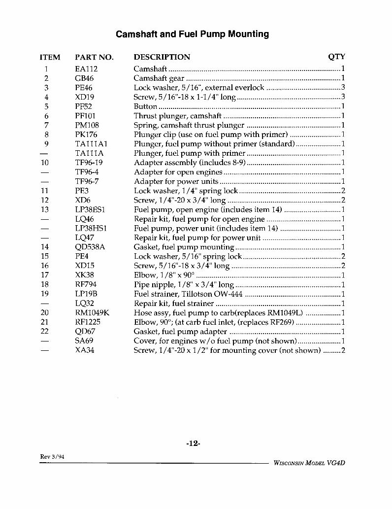
Camshaft and Fuel Pump Mounting
ITEM
123456789
10
111213
141516171819
202122
PART NO.
EAl12GB46PE46XD19PF52PF101PM108PK176TA111A1TA111ATF96-19TF96-4TF96-7PE3XD6LP38ES1LQ46LP38HS1LQ47QD538APE4XD15XK38RF794LP19BLQ32RM1049KRF1225QD67SA69XA34
DESCRIPTION QTY
Camshaft ........................................................................................1Camshaft gear ............................................................................... 1Lock washer, 5 / 16", external everlock ...................................... 3Screw, 5/16"-18 x 1-1/4" long ..................................................... 3Button .............................................................................................1Thrust plunger, camshaft ............................................................ 1Spring, camshaft thrust plunger ................................................ 1Plunger clip (use on fuel pump with primer) .......................... 1Plunger, fuel pump without primer (standard) ....................... 1Plunger, fuel pump with primer ................................................ 1Adapter assembly (includes 8-9) ................................................ 1Adapter for open engines ............................................................ 1Adapter for power units .............................................................. 1Lock washer, 1/4" spring lock .................................................... 2Screw, 1/4"-20 x 3/4" long .......................................................... 2Fuel pump, open engine (includes item 14) ............................. 1Repair kit, fuel pump for open engine ...................................... 1Fuel pump, power unit (includes item 14) ............................... 1Repair kit, fuel pump for power unit ........................................ 1Gasket, fuel pump mounting ...................................................... 1Lock washer, 5/16" spring lock .................................................. 2Screw, 5/16"-18 x 3/4" long ........................................................ 2Elbow, 1/8"x 90° .......................................................................... 1Pipe nipple, 1/8" x 3/4" long ...................................................... 1Fuel strainer, Tillotson OW-444 ................................................. 1Repair kit, fuel strainer ................................................................ 1Hose assy, fuel pump to carb(replaces RM1049L) .................. 1Elbow, 90°; (at carb fuel inlet, (replaces RF269) ....................... 1Gasket, fuel pump adapter ......................................................... 1Cover, for engines w/o fuel pump (not shown) ...................... 1Screw, 1/4"-20 x 1/2" for mounting cover (not shown) ......... 2
-12-
Rev 3/94WISCONSIN MODEL VG4D

3
---------7

Oil Filter and Oil Filler Mounting
ITEM
12345
6789
10111213141516171819
PART NO.
LJ300MLO60-1RJ173RF1495ARV5254RV52A1QD595APE4XD17BRF1225RM536GC28-1pJ105BG223PE4XD17XE55PF18RF1536RV52ARC91
DESCRIPTION QTY
Oil filler tube .................................................................................1Oil filler and breather cap ........................................................... 1Dipstick, 10" long, standard ........................................................ 1Adapter tube, dipstick (mount with "Loctite"), std ................ 1Oil filter cartridges, 4 pack .......................................................... 1Oil filter base assembly ................................................................ 1Gasket, oil filter mounting .......................................................... 1Lock washer, 5/16", spring lock ................................................. 2Screw, oil filter mounting (special 5/16"-18 x 1") .................... 2Elbow, oil line to governor .......................................................... 1Oil line, crankcase to governor ................................................... 1Idler gear (includes HG279 bushing) ........................................ 1Stud, idler gear ..............................................................................1Plate, bearing retainer, flywheel end ......................................... 1Lock washer, 5/16" for bearing retainer plate ......................... 6Screw, 5/16"-18 x 1" long for bearing retainer plate ............... 6Screw, 5/16"-18 x 3/8" long, Allen head set ............................. 1Pipe plug, 1/8" slotted ................................................................. 9Stud, oil filter (not shown) .......................................................... 1Base, oil filter, after S/N 5984980 ............................................... 1Screen, oil filler (optional) (not illustrated) .............................. 1
-14-
WISCONSIN MODEL VG4D

4 2

Oil Pump Assembly
ITEM
12
3456789
101112131415161718192021
PART NO.
* K129KA61D2S1
* KD121B
KD122A* KC66
PA64PL137GD94CPD195QD535A
KB42S2ME60PM111X[16RDl12PE14XA7XA8XA56P]143BPF18RFll21
DESCRIPTION QTYOil pump assembly (replaces K95L) .......................................... 1Body assembly, oil pump (includes items 2-5) ........................ 1Shaft, oil pump drive (includes item 4)(replaces KD121S1) ....................................................................... 1Stub shaft .......................................................................................1Gear, driver and driven (replaces KC56A) ............................... 2Pin, oil pump gear 1/8" dia. x 3/4" long ................................... 1Woodruff key, No. 1, oil pump drive gear ............................... 1Gear, oil pump drive .................................................................... 1Nut, oil pump gear ....................................................................... 1Gasket, oil pump cover(not included in engine gasket set) ............................................ 1Cover assembly (includes 11-16) ................................................ 1Steel ball, 1/4" dia ........................................................................ 1Spring, relief valve ....................................................................... 1Cotter pin, relief valve, 1/8" x 1". ............................................... 1Screen, oil pump ........................................................................... 1Lock washer, #10 spring lock ...................................................... 7Screw, #10-32 x 3/8" long, oil pump screen ............................. 1Screw, #10-32 x 1/2" long, oil pump cover ............................... 4Screw, #10-32 x 1-1/4" long, oil pump cover ............................ 2Lock screw, oil pump ................................................................... 1Pipe plug, 1/8" slotted ................................................................. 3Nozzle, oil spray ........................................................................... 4
* For engines with serial number 6178652 and after.
-16-
WISCONSIN MODEL VG4D


Magneto and Gear Cover
ITEM
123456789
10
11121314
15161718192021
2223
24
2526
27
PART NO.
YL339-32YL339-38YL339-34YL339-42PD79PD11PE5XD33PH22AY97S1
QD616GD103-1PC429BD101S1
BD101BS1
QD634WE243QD633PA291PF52XK3PD78
PE4XD17
XD19
PH269XD15XD20XD15
DESCRIPTION QTY
Ignition cable, No. 1 cylinder (includes boot) .......................... 1Ignition cable, No. 2 cylinder (includes boot) .......................... 1Ignition cable, No. 3 cylinder (includes boot) .......................... 1Ignition cable, No. 4 cylinder (includes boot) .......................... 1Nut, 3/8"-16 ...................................................................................1Nut, 3/8"-24 ...................................................................................1Lock washer, 3/8" spring lock .................................................... 2Screw, 3/8"-16 x 2-1/4". ............................................................... 1Washer, 3/8" x 11/16" x 3/32" thick, plain steel ...................... 1Magneto with gear, Fairbanks-Morse No. FMX-4B7A(replaces Y95S1) ............................................................................ 1Gasket, magneto mounting ......................................................... 1Magneto gear (replaces GD103) ................................................. 1Stud, magneto mounting upper hole ........................................ 1Gear cover, standard (includes 19-20, 25;also TC388-1 governor shaft) ...................................................... 1Gear cover assembly (includes 19-20, 25;also TC388-1 governor shaft for flywheel alternators) ........... 1Gasket, gear cover ........................................................................ 1Gear cover spacer ......................................................................... 1Gasket, crankcase to spacer ......................................................... 1Dowel pin, gear cover to case ..................................................... 2Button, camshaft thrust planger ................................................. 1Pipe plug, 3/8" square head for timing hole in gear cover .... 1Nut, 5/16"-18 threadfor spacer to gear cover - left side .............................................. 1Lock washer, 5/16" spring lock ................................................ 17Screw, 5/16"-18 x 1" longfor spacer to gear cover - left side .............................................. 1Screw, 5/16"-18 x 1-1/4" longfor mounting gear cover ............................................................ 10Oil seal, crankshaft ....................................................................... 1Screw, 5/16"-18 x 3/4", spacer plate to gear cover .................. 3Rubber nipple for magneto Towers (not illustrated) .............. 4Screw, 5/16" x 3/4" long, spacer plate to crankcase ............... 5
* See page 34 for kits
-18-
WISCONSIN MODEL VG4D


Governor Assembly
ITEM
23456789
10
1213
15161718
20
22232425
PART NO.
T134LTC395S1TC398PH571VB151PA367SA52RF269-2QD615APF18TC388-1TC535S1GD150TC322DS1PA340PH313ATC391DPE4XD16PM76PI 145TC367APD77PD173AVE875S1PK181TC328D
DESCRIPTION QTYGovernor assembly replaces T891. for ~er\’i~ ~.. ......................... 1Governor housing assemblv (include.- item.- 2-9) ................... 1Cross shaft and lever .................................................................... 1Oil seal, governor cross shaft (Neoprep, c) .................................Governor yoke .............................................................................. 1Roll pin, 1/8"x 3/4" long ............................................................ 1Plug, 1/2" expansion .................................................................... 1Fitting .............................................................................................Gasket, governor housing ........................................................... 1Pipe plug, 1/8" slotted, governor houbing ............................... 1Governor shaft (press fit into gear cover) .................................Governor flyweight assembly (includes items 12-15, 26) .......Governor gear ............................................................................... 1Flyweight (includes item 26) ...................................................... 2Roll pin ...........................................................................................2Washer ...........................................................................................1Thrust sleeve and bearing ........................................................... 1Lock washer, 5/16" . ................................................................... 10Screw, 5/16"-18 x 7/8" long ........................................................ 4Governor spring ........................................................................... 1Adjusting screw, governor spring tension ............................... 1Adjusting screw pin ..................................................................... 1Nut, 1/4"-20 thread ...................................................................... 1Nut, spring tension adjustment .................................................. 1Control rod, (includes item 25) ................................................... 1Clip, 3/64" x 3/8" long ................................................................ 1Thrust pin, governor flyweight (not illustrated) ..................... 2
-20-
MODEL VG4D


Air Shrouding
ITEM
1
23456789
10
111213141516171819202122
PART NO.
SE124BGSE124C
SE124AM
SE 124AP
PE4XD172PE5XD171SE48PE3XA33SE126SE126ASE126A3
SE126A11
SE126A14
SE128CSE128BXA34SE127SE127ASE125ASE125PG314PG475XA65SD312AXA67SD314
DESCRIPTION QTY
Flywheel shroud, standard ......................................................... 1Flywheel shroud, with pads for starterand air cleaner mounting ............................................................ 1Flywheel shroud, for flywheel alternator and withpad for electric starter .................................................................. 1Flywheel shroud, for flywheel alternator, withpads for starter and air cleaner ................................................... 1Lock washer, 5/16" spring lock .................................................. 4Screw, 5/16"-18 thread x 1/2" long ............................................ 4Lock washer, 3/8" spring lock .................................................... 2Screw, 3/8"-16 x 1/2" long .......................................................... 2Screen, flywheel shroud .............................................................. 1Lock washer, 1/4" spring lock .................................................. 38Screw, 1/4"-20 x 3/8" long ........................................................ 36Lower cylinder shroud, right side ............................................. 1Lower cylinder shroud, left side, magneto ignition ................ 1Lower cylinder shroud, left side,provision for mounting coil ........................................................ 1Lower cylinder shroud, left side, battery ignitionand 10 or 25 amp flywheel alternator ........................................ 1Lower cylinder shroud, left side, battery ignitionand 30 amp flywheel alternator ................................................. 1Heat deflector, left side ................................................................ 1Heat deflector, right side ............................................................. 1Screw, 1/4"-20 x 1/2" long .......................................................... 2Cylinder head shroud, right side ............................................... 1Cylinder head shroud, left side .................................................. 1Rear shroud cover, left side ........................................................ 1Rear shroud cover, right side ...................................................... 1Clip, spark plug cable .................................................................. 2Bracket, choke control .................................................................. 1Screw, #8 x 1/2" long, for choke control bracket ..................... 2Engine name plate ........................................................................ 1Screw, #4 x 1/4" long, for mounting name plate ..................... 4Decal, warning .............................................................................. 1
-22-
Rev 12/90WISCONSIN MODEL VG4D


Engine Gask t Set
ITEM
12345
6789
101112131415
PART NO.Q18CQB83QC66QC12AQD67QD636AQD636BQD616QD482QD615AQD632QD634QD633QD538AQD635QD631QD595A
DESCRIPTION QTYOverhaul gasket set (includes items 1-15) ................................ 1Insert, manifold gasket ................................................................ 6Gasket, manifold (replaces QC62) ............................................. 6Gasket,Gasket,Gasket,Gasket,Gasket,Gasket,Gasket,Gasket,Gasket,Gasket,Gasket,Gasket,Gasket,Gasket,
carburetor ........................................................................3fuel pump adapter to crankcase ................................... 1main bearing plate, .003". .............................................. 3main bearing plate, .006". .............................................. 3magneto ...........................................................................1valve inspection cover ................................................... 4governor housing ........................................................... 1cylinder base ................................................................... 2gear cover to spacer plate .............................................. 1crankcase to spacer plate ............................................... 1fuel pump ........................................................................1bottom plate, oil pan ...................................................... 1cylinder head .................................................................. 2oil filter mounting pad .................................................. 1
-24-
MODEL VG4D

Notes
-25-

Wisconsin Options
for the VG4D
¯ Carburetors¯ Magnetos¯ Distributors¯ Starters

19
35
36
37
----38
~.--.-39
40 41 42
~44 ~

L57-1 Carburetor (Facet No. 11532)
ITEM12
2A2B2C3456789
10111213141516171819202122232425262728293031
PART NO.
93T8S8-793C105-393C106-293T22S893T41-1093Cl12-1293C140-5893T41-893T8S8-893Cl10-793C109-6093C131-4x293T57-493T21S893T63-993C130-493T52-5793T48-993C9-7593C46-4993Cl11-15593C21-4293T315S5-4
93T8S8-1093CR27-24193C29-1037
93CR37-1x193C102-11393T315S5-493T56-2093C81-17-35
DESCRIPTION QTYScrew, lever swivel ....................................................................... 1Shaft, choke ...................................................................................1Lever, choke ..................................................................................1Nut, choke lever ............................................................................ 1Lock washer, choke lever nut ..................................................... 1Spring, choke lever ....................................................................... 1Screw, bracket (includes item 5) ................................................. 2Lock washer, bracket ................................................................... 2Screw, tube clamp ........................................................................ 1Clamp, bracket .............................................................................. 1Bracket, choke (includes items 6-7, 11) ...................................... 1Retainer, choke shaft packing ..................................................... 1Washer, choke shaft packing ...................................................... 1Nut, clamp screw .......................................................................... 1Pin, washer retaining ................................................................... 1Washer, shaft thrust ..................................................................... 1Retainer, throttle shaft packing .................................................. 2Seal, throttle shaft ......................................................................... 2Bushing, throttle shaft .................................................................. 2Needle, idle adjusting .................................................................. 1Spring, adjusting needle .............................................................. 1Plate, throttle .................................................................................1Screw, throttle plate ..................................................................... 2Roll pin, throttle lever .................................................................. 1Screw, lever stopLever and stop, throttle ............................................................... 1Shaft and lever, throttle (includes items 12 - 13, 21 - 23) ........ 1Shaft, throttle .................................................................................1Body, throttle ................................................................................1Plug, choke shaft hole .................................................................. 1Plate, choke ....................................................................................1Screw, choke plate ........................................................................ 2Fiber washer, fuel valve seat ....................................................... 1Valve and seat, fuel ...................................................................... 1
(Continued on page 30)
-28-
WISCONSIN MODEL VG4D

35
36
37
...--- 38

L57-1 Carburetor (Facet No. 11532) (cont.)
ITEM
32333435363738394041424344454647
PART NO.
93C66-104-4293T56-7393C76-50-193C120-1893C85-9793C142-5593C52-2-1293B3-129A93T56-2493C52-7-3893T56-2393C138-2493T91-393T301S8-1493T301S8-9QC12A
DESCRIPTION QTY
Jet, discharge .................................................................................1Fiber washer, well ........................................................................ 1Well, metering ............................................................................... 1Axle, float .......................................................................................1Float assembly ............................................................................... 1Gasket, bowl to body ................................................................... 1Jet, idle ............................................................................................1Bowl, fuel (replaces 93-B398A) ................................................... 1Fiber washer, main jet .................................................................. 1Jet, main .........................................................................................1Fiber washer, passage plug ......................................................... 1Plug, main passage ....................................................................... 1Plug, 1/8" pipe, bowl drain ........................................................ 1Screw, bowl to body, long ........................................................... 2Screw, bowl to body, short .............................. ~... ........................1Gasket, flange (Facet C141-4-6) .................................................. 3
93C181-296 Gasket set (includes items 30, 33, 35, 37, 40, 42) ....................... 1
LQ37 Repair kit (includes items 9-10, 14-15, 17, 20, 27, 31,33, 35, 37, 40, 42, 47) ...................................................................... 1
* Not serviced separately
-30-
WISCONSIN MODEL VG4D


Magneto #Y97S1 (Fairbanks-Morse Type FM X487A)
ITEM
123456789
1011121314151617181920212223242526272829303132333435
PART NO.
31-8S9D31W80031B68231E2460B31M276531A276631G250131-10S14D31AZ243031H249831D149831Q595231-6S6U31D245831C1498G31A2437A31-6S6Z31-8S6U3113596931G278831-8S5NA31AXMR243331Y593931D5950C31J983A31-8S6G31X463131G149831A5950A31L2514C31o8N131-8LW531M251431C601831K2457A
DESCRIPTION QTYScrew, cover, #8-32 x 9/16" long ................................................ 2Cover, end cap .............................................................................. 1Gasket, end cap cover .................................................................. 1Brush and spring .......................................................................... 1Distributor rotor ........................................................................... 1Spring clip, rotor ........................................................................... 1Seal, distributor shaft ................................................................... 1Screw, end cap, #10-24 x 7/8" long ............................................ 4End cap ..........................................................................................1Gasket, end cap ............................................................................. 1Snap ring, rotor gear .................................................................... 1Rotor gear ......................................................................................1Support screw, #6-32 x 3/8" long ............................................... 1Washer, support screw, #6 .......................................................... 1Snap ring, fulcrum pin ................................................................. 1Point set, clockwise ...................................................................... 1Terminal screw, #6-32 x 3/8" long ............................................. 1Support screw #8-32 x 3/8" long ................................................ 1Washer, support screw, #8 .......................................................... 1Cam wick, clockwise .................................................................... 1Screw, condenser, #8-32 x 5/16" long ........................................ 1Condenser ......................................................................................1Shaft and gear, distributor .......................................................... 1Bearing, distributor ...................................................................... 1Lead rod .........................................................................................1Support screw, #8-32 x 3/8" long ............................................... 4Support, bearing ........................................................................... 1Snap ring, distributor shaft ......................................................... 1Bearing, cam end .......................................................................... 1Switch, assembly .......................................................................... 1Nut, switch screw ......................................................................... 3Lock washer, switch screw .......................................................... 1Insulated lever .............................................................................. 1Insulating washer ......................................................................... 2Insulating bushing ........................................................................ 1
continued on page 34
-32-
WISCONSIN MODEL VG4D


Magneto #Y97S1 (Fairbanks-Morse Type FM-X4B7A) (cont.)
ITEM
36373839404142434445464748495O5152535455565758596061626364
PART NO.
31J2499A31-8S14N31-6S4U31D612031R2477C31HW248031-3K131B1498B31C594931B1498D31TZ242531-31SS14A31N19531-6S4U31B6030A31C6032B31S256831A2492C31G386131A2492A31BW2563C-2731A1498J31Q256631S596331S2563-2731E256531Y5957311F257231M2570GD103-1
DESCRIPTION QTY
Wire assembly ............................................................................... 1Screw, switch, #8-32 x 7/8" long ................................................ 1Screw, clip, #6-32 x 1/4" long ..................................................... 1Coil clip ..........................................................................................1Coil ..................................................................................................1Magnetic rotor ............................................................................... 1Key ..................................................................................................1Snap ring, bearing ........................................................................ 1Bearing, drive end ........................................................................ 1Snap ring, shaft ............................................................................. 1Housing ..........................................................................................1Setscrew, coil, 5/16"-24 x 7/8" long ........................................... 2Name plate ....................................................................................1Screw, cover, #6-32 x 1/4" long .................................................. 2Vent cover ......................................................................................2Vent screen ....................................................................................2Stop pin, pawl ............................................................................... 1Washer, seal (inner) ...................................................................... 1Shaft seal ........................................................................................1Washer, seal (outer) ...................................................................... 1Coupling, complete (27° lag angle) ............................................ 1Lock spring, pawl ......................................................................... 1Coupling pawl .............................................................................. 2Pawl spring ....................................................................................2Hub assembly (27° lag angle) ..................................................... 1Coupling spring ............................................................................ 1Coupling shell ............................................................................... 1Bushing ..........................................................................................1Coupling nut ................................................................................. 1Drive gear ......................................................................................1
YQ8 Points and condenser kit (includes items 16-17, 20, 22) .......... 1
YQ9 Overhaul kit (includes items 3, 8, 10, 16-17, 20, 22,28-29, 32, 43, 53-54) ....................................................................... 1
-34-
WISCONSIN MODEL VG4D

ITEM PART NO.
2 YL394-18
3 31-13001655-- YQ26
-- PG54341
31-1300166610 t31-13001661-- t31-13001677
31-13001678
YF45S1, YF45AS1, YF45B Colt DistributorUSE WITH MODELS VG4D, VH4D, V465D, W4-1770
10
CONDENSOR CAPACITYPOINT CAPSHAFT END PLAY
DISTRIBUTOR
YF45YF45A
YF45B
.18-.23 HFD
.018"-.022"
.010"
APPLICATION
VH4D, VG4D, V465DVH4D, W4-1770,(TOP MOUNTED)VG4D (TOP MOUNTED)
DESCRIPTION QTY
Washer thrust ..................... 2Extension wire(not used with YF453) ........ 1Clip .......................................1Breaker kit (includes 4, 5,14, 15, 19) ............................ 1Condenser assembly .......... 1Screw ................................... 1Advance arm kit(includes 6, 7) ...................... 1Advance arm assembly ..... 1Washer ................................ 1Gear .....................................1Pin ........................................1Shaft kit (includes 10, 11)...1Spring kit ............................. 1Gear kit (YF45)(includes 1, 8, 9) .................. 1Gear kit (YF45A)(includes 1, 8, 9, 20) ............ 1
ITEM PART NO. DESCRIPTION QTY
t 31-13001679
12 31-1300161613 31-1300159814 * ....15 *------
16 31-13001604-- YQ27
17 f31-130016071819
Gear kit (YF45B)(includes 1, 8, 9) .................. 1Shaft assembly ................... 1Insert ....................................2Breaker plate ....................... 1Breaker set .......................... 1Screw and washerassembly ............................. 1Shield .................................. 1Distributor cap and rotorkit (includes 17, 18) ............. 1Rotor ....................................1Cap .......................................1Lube capsule(not illustrated) ................... 1Spacer (not illustrated) ....... 1
* Not serviced separately.
Also sold separately.
-35-
Wisconsin Distributors

YF50S1, YF50AS1 Ignition Distributor
USE WITH MODELS VH4D, W4-1770, VG4D, V465D
I
11
10
.%ITEM PART NO.
SHAFT END PLAY: .001" o .015"
DESCRIPTION QTY
-- 20121003
2 201200153 20120012-- 20121001
8 20120005
9 20120004-- 20121006
10 t2012001111 t 2012001012 2012000313-- YL394-18-- YL396A18
Distributor cap and gasket(includes 1, 11) ................... 1Vented distributor cap ....... 1Advance weights set .......... 1Advance spring set ............ 1Gear kit (includes 4-7) ........ 1Thrust washer set .............. 1Spacer (YF50AS1) .............. 1Gear ..................................... 1Roll pin ................................ 1Electronic module(includes screws) ............... 1Magnet assembly ............... 1Rotor and spacer(includes 10, 13) ................. 1Rotor spacer ....................... 1Distributor cap gasket ........ 1Dust cover ........................... 1Rotor ................................... 1Wire, extension-Black .......... 1Wire, extension-Red ............ 1
* Not serviced separately.
Also sold separately.
-36-
Wisconsin Distributors
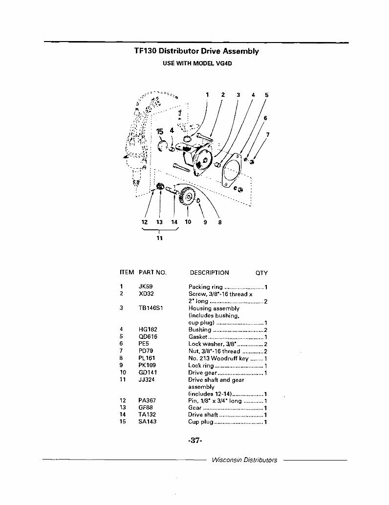
TF130 Distributor Drive Assembly
USE WITH MODEL VG4D
ITEM PART NO.
1 JK592 XD32
3 TB146S1
4 HG1825 QD6166 PE57 PD798 PL1619 PK10910 GD14111 JJ324
12 PA36713 GF8814 TA13215 SA143
DESCRIPTION QTY
Packing ring ........................ 1Screw, 3/8"-16 thread x2" long ................................. 2Housing assembly(includes bushing,cup plug) ............................. 1Bushing ............................... 2Gasket .................................. 1Lock washer, 3/8". ............... 2Nut, 3/8"-16 thread ............. 2No. 213 Woodruff key ........ 1Lock ring .............................. 1Drive gear ............................ 1Drive shaft and gearassembly(includes 12-14) ................... 1Pin, 1/8" x 3/4" long ............ 1Gear ..................................... 1Drive shaft ........................... 1Cup plug .............................. 1
Wisconsin Distributors
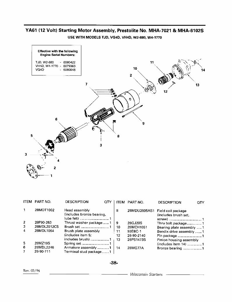
YA61 (12 Volt) Starting Motor Assembly, Prestolite No. MHA-7021 & MHA-6102SUSE WITH MODELS TJD, VG4D, VH4D, W2-880, W4-1770
ITEM PART NO.
1 28MDT1002
2 28P90-2633 28MDL2012CS4 28MDL1064
5 28MZ19S6 28MDL22467 28-90-711
DESCRIPTION QTY
Head assembly(includes bronze bearing,lube felt) .............................. 1Thrust washer package ...... 1Brush set ............................. 1Brush plate assembly(includes item 5;includes brush) ................... 1Spring set ............................ 1Armature assembly ............ 1Terminal stud package ....... 1
ITEM PART NO.
8 28MDU2005AS1
9 28GJ20S10 28MCH105111 93EBC-112 28-90-214013 28PS1473S
14 28MG77A
DESCRIPTION QTY
Field coil package(includes brush set,screw) .................................. 1Thru bolt package ............... 1Bearing plate assembly ..... 1Bendix drive assembly ....... 1Pin package ......................... 1Pinion housing assembly(includes item 14) ............... 1Bronze bearing ................... 1
-38-
Rev. 03/94Wisconsin Starters

EEA102 (12 Volt) Starting Motor Assembly
USE WITH MODEL VG4D
ITEM
1
2
89
PART NO.
YL356-26
Y/356-28YA61
YA55A
PG515D
PC396PE4PD10PB187
PE5YD296
DESCRIPTION QTY
Starter cable assembly,26" long .............................. 1Cable, 28" long ................... 1Starting motor, 12 volt,Prestolite MHA7021(replaces YA54A) ............... 1Starting motor, 6 volt,Prestolite MZ4212(replaces YA19-3, YA10) .... 1Support bracket(replaces PG515A) ............. 1Stud ....................................2Lock washer, 5/16". ............ 2Nut, 5/16"-24 thread ........... 2Screw,3/8"-24 thread x 1 ̄ long ..... 3Lock washer, 3/8". .............. 3Terminal connector ........... 1
-39-
Wisconsin Starters

SERVICE AND PARTSAvailable from your Authorized
WISCONSIN MOTORSService Center