Embed Size (px)
Citation preview
...J
...J w 0 0 ::i z 0::: w u.
~
I 0
b
12"
N T'"
:::ii: :::ii: :::::> :::::> :::ii: :::ii:
~~ :::ii: :::ii: bb in <O
' ' 1 _ _J_
0 0
0
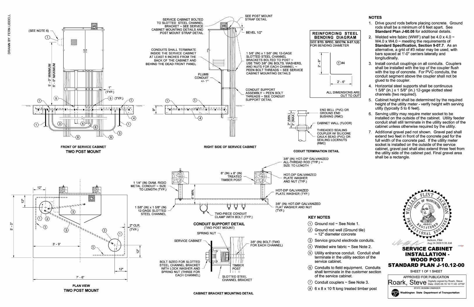
FRONT OF SERVICE CABINET
TWO POST MOUNT
2
3' - 9"
7' - 6"
PLAN VIEW
TWO POST MOUNT
" --..;:
12"
II II II
SERVICE CABINET BOLTED TO SLOTTED STEEL CHANNEL
BRACKET - SEE SERVICE CABINET MOUNTING DETAILS AND
POST MOUNT STRAP DETAIL
CONDUITS SHALL TERMINATE INSIDE THE SERVICE CABINET
AT LEAST 6 INCHES FROM THE BACK OF THE CABINET AND
BEHIND THE DEAD FRONT PANEL
1 1/4" (IN) DIAM. RIGID METAL CONDUIT - SIZE
TO LENGTH (TYP.)
1 5/8" (IN) x 1 5/8" (IN) 12-GAGE SLOTTED
STEEL CHANNEL
SEE POST MOUNT STRAP DETAIL
BEVEL 1/2"
1 5/8" (IN) x 1 5/8" (IN) 12-GAGE SLOTTED STEEL CHANNEL BRACKETS BOLTED TO POST -USE TWO 3/8" (IN) BOLTS, WASHERS, AND NUTS FOR EACH CHANNEL -PEEN BOLT THREADS - SEE SERVICE CABINET MOUNTING DETAILS
CONDUIT SUPPORT ASSEMBLY - PEEN BOLT THREADS - SEE CONDUIT SUPPORT DETAIL
REINFORCING STEEL BENDING DIAGRAM
SEE STD. SPEC. SECTN. 9-07.1(2) FOR BENDING DIAMETER
[L:_ 1. 2' - 6" .1
ALL DIMENSIONS ARE OUT TO OUT
END BELL (PVC) OR .L-----1;---~ GROUNDEND
BUSHING (RMC)
CABINET WALL (FLOOR)
THREADED SEALING COUPLER W/ SILICONE CAULK BEAD (PVC) OR SEALING LOCKNUTS (RMC)
RIGHT SIDE OF SERVICE CABINET
6" (IN) x 8" (IN) TREATED
TIMBER POST
TWO-PIECE CONDUIT CLAMP WITH BOLT (TYP.)
CODUIT TERMINATION DETAIL
3/8" (IN) HOT-DIP GALVANIZED ALL-THREAD ROD (TYP.) -SIZE TO LENGTH
HOT-DIP GALVANIZED PLATE WASHER AND NUT (TYP.)
HOT-DIP GALVANIZED PLATE WASHER (TYP.)
3/8" (IN) HOT-DIP GALVANIZED FLAT WASHER AND NUT (TYP.)
KEYNOTES
NOTES
1. Drive gound rods before placing concrete. Ground rods shall be a minimum of 6 feet apart. See Standard Plan J-60.05 for additional details.
2. Welded wire fabirc (WWF) shall be 4.0 x 4.0 -W4.0 x W4.0 - meeting the requirements of Standard Specification, Section 9-07.7. As an alternative, a grid of #3 rebar may be used, with bars spaced at 1 '-0" centers laterally and longitudinally.
3. Install conduit couplings on all conduits. Couplers shall be installed with the top of the coupler flush with the top of concrete. For PVC conduits, the conduit segment above the coupler shall not be glued to the coupler.
4. Horizontal steel supports shall be continuous 1 5/8" (in.) x 1 5/8" (in.) 12-gage slotted steel channels (two required).
5. Cabinet height shall be determined by the required height of the utility meter - verify height with serving utilty (typically 5 to 6 feet).
6. Serving utility may require meter socket to be installed on the outside of the cabinet. Utility feeder conduit shall still terminate in the utility section of the cabinet unless otherwise required by the utility.
7. Additional gravel pad not shown. Gravel pad shall extend two feet in front of the concrete pad for the full width of the concrete pad. If the utility meter socket is installed on the outside of the service cabinet, gravel pad shall also extend three feet from the utility side of the cabinet pad. Final gravel area shall be a rectangle.
2" CLR.
(TYP.)
CONDUIT SUPPORT DETAIL (TWO POST MOUNT)
(D Ground rod - See Note 1.
0 Ground rod well (Ground tile) SPRING NUT
SERVICE CABINET 3/8" (IN) BOLT (TWO FOR EACH CHANNEL)
BOLT SIZED FOR SLOTTED STEEL CHANNEL BRACKET
WITH LOCK WASHER AND SPRING NUT (THREE FOR
EACH CHANNEL)
1-==:;:::::=:::::::'...jl TIMBER POST I I /I
SLOTTED STEEL CHANNEL BRACKET
CABINET BRACKET MOUNTING DETAIL
- 12" diameter concrete
@ Service ground electrode conduits.
© Welded wire fabric - See Note 2.
® Utility entrance conduit. Conduit shall terminate in the utility section of the service cabinet.
® Conduits to field equipment. Conduits shall terminate in the customer section of the service cabinet.
0 Conduit couplers - See Note 3.
® 6 x 8 x 10 ft long treated timber post
~~~E ~!!~;;~T ~ INSTALLATION -
WOOD POST STANDARD PLAN J-10.12-00
SHEET 1 OF 1 SHEET
APPROVED FOR PUBLICATION
STATE DESIGN ENGINEER ... VI Washington State Department of Transportation