Embed Size (px)
Citation preview

Service Bulletin 13-006
February 22, 2013Applies To: 2009–10 TSX L4 with M/T – ALL2009–10 TSX: Sticking Rings Resulting in Unusually High Engine Oil Consumption
SYMPTOMThe engine oil level is low on the dipstick, and the oil warning light may come on in rare high oil consumption situations.
POSSIBLE CAUSEUnder certain specific circumstances the engine may create deposits on the oil control rings, which may lead to increased oil consumption when all of the following conditions occur simultaneously on a regular and prolonged basis:
• The engine is cold (not warmed up to operating temperature)
• Hard acceleration while the engine is cold
• The fuel used has an unusually high concentration of particles - Acura recommends using Top Tier gas that contains detergents to prevent deposits. For more information about Top Tier gas, go to www.toptiergas.com.
All these conditions happening at the same time are rare, but if they do occur, deposits may form over years of driving under these conditions. If the oil control rings begin to stick because of the deposits, the client may subsequently complain about excessive oil consumption.
CORRECTIVE ACTIONReplace all the engine pistons and the piston rings.
Service Consultant:Talk to the client about the many factors contributing to oil consumption. Remind clients that with less frequent service intervals for modern engines, it’s not uncommon for a client to add oil between services. Therefore, it’s a good idea for clients to check their engine oil regularly (as recommended in the Owner’s Manual) and add oil as necessary.
PARTS INFORMATIONBolt-Washer (Head Bolt) (ten may be required):
P/N 90005-RNA-A01
Chain Case Gasket Kit: P/N 06114-R40-J01
Connecting Rod Bolt (eight may be required): P/N 13204-RBB-004
Cylinder Head Gasket Kit: P/N 06110-R44-A00
Flexible Exhaust Gasket: P/N 18229-SEA-013
Flange Bolt (12x45): P/N 90165-SDA-A00
Flange Bolt (12x65): P/N 90168-TA0-A00
Flange Bolt (12x30) (two required): P/N 90176-SKN-000
Intake Manifold Gasket (four required): P/N 17115-R40-A01
Primary Converter Gasket: P/N 18115-R40-A01
Piston Ring Set (four required): P/N 13011-RL5-A01
Piston Set A: P/N 13010-RL5-A00(Go to ORDERING PISTONS on page 16 for more information about which piston set you need.)
Piston Set B: P/N 13020-RL5-A00(Go to ORDERING PISTONS on page 16 for more information about which piston set you need.)
NOTE: You need a total of four piston sets, but you will probably need a mix of both A and B piston sets.
TOOL INFORMATION• Camshaft Lock Pin Set: T/N 07AAB-RWCA120
• Gasket Remover/Pan Separator: T/N LIL50190
• Piston Ring Expander (Snap-On T/N PRS8 or equivalent)
• Piston Ring Compressor (SCP1287 or equivalent)
• 1/2 in. Drive Torque Angle Gauge (commercially-available)
• Engine Hanger: P/N AAR-T1256
2013 American Honda Motor Co., Inc. – All Rights Reserved BTB 49236 (1302) 1 of 16
CLIENT INFORMATION: The information in this bulletin is intended for use only by skilled technicians who have the proper tools, equipment, andtraining to correctly and safely maintain your vehicle. These procedures should not be attempted by “do-it-yourselfers,” and you should not assume thisbulletin applies to your vehicle, or that your vehicle has the condition described. To determine whether this information applies, contact an authorizedAcura automobile dealer.
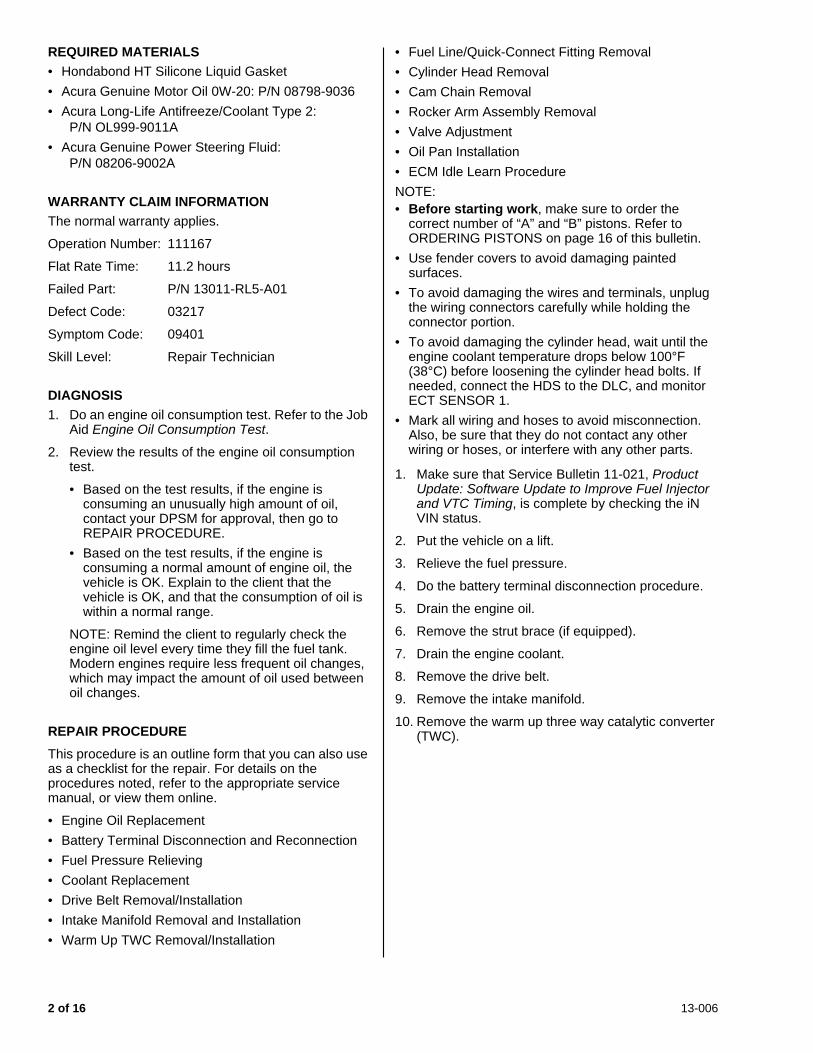
REQUIRED MATERIALS• Hondabond HT Silicone Liquid Gasket
• Acura Genuine Motor Oil 0W-20: P/N 08798-9036
• Acura Long-Life Antifreeze/Coolant Type 2:P/N OL999-9011A
• Acura Genuine Power Steering Fluid:P/N 08206-9002A
WARRANTY CLAIM INFORMATIONThe normal warranty applies.
Operation Number: 111167
Flat Rate Time: 11.2 hours
Failed Part: P/N 13011-RL5-A01
Defect Code: 03217
Symptom Code: 09401
Skill Level: Repair Technician
DIAGNOSIS1. Do an engine oil consumption test. Refer to the Job
Aid Engine Oil Consumption Test.
2. Review the results of the engine oil consumption test.
• Based on the test results, if the engine is consuming an unusually high amount of oil, contact your DPSM for approval, then go to REPAIR PROCEDURE.
• Based on the test results, if the engine is consuming a normal amount of engine oil, the vehicle is OK. Explain to the client that the vehicle is OK, and that the consumption of oil is within a normal range.
NOTE: Remind the client to regularly check the engine oil level every time they fill the fuel tank. Modern engines require less frequent oil changes, which may impact the amount of oil used between oil changes.
REPAIR PROCEDURE
This procedure is an outline form that you can also use as a checklist for the repair. For details on the procedures noted, refer to the appropriate service manual, or view them online.
• Engine Oil Replacement
• Battery Terminal Disconnection and Reconnection
• Fuel Pressure Relieving
• Coolant Replacement
• Drive Belt Removal/Installation
• Intake Manifold Removal and Installation
• Warm Up TWC Removal/Installation
• Fuel Line/Quick-Connect Fitting Removal
• Cylinder Head Removal
• Cam Chain Removal
• Rocker Arm Assembly Removal
• Valve Adjustment
• Oil Pan Installation
• ECM Idle Learn Procedure
NOTE: • Before starting work, make sure to order the
correct number of “A” and “B” pistons. Refer to ORDERING PISTONS on page 16 of this bulletin.
• Use fender covers to avoid damaging painted surfaces.
• To avoid damaging the wires and terminals, unplug the wiring connectors carefully while holding the connector portion.
• To avoid damaging the cylinder head, wait until the engine coolant temperature drops below 100°F (38°C) before loosening the cylinder head bolts. If needed, connect the HDS to the DLC, and monitor ECT SENSOR 1.
• Mark all wiring and hoses to avoid misconnection. Also, be sure that they do not contact any other wiring or hoses, or interfere with any other parts.
1. Make sure that Service Bulletin 11-021, Product Update: Software Update to Improve Fuel Injector and VTC Timing, is complete by checking the iN VIN status.
2. Put the vehicle on a lift.
3. Relieve the fuel pressure.
4. Do the battery terminal disconnection procedure.
5. Drain the engine oil.
6. Remove the strut brace (if equipped).
7. Drain the engine coolant.
8. Remove the drive belt.
9. Remove the intake manifold.
10. Remove the warm up three way catalytic converter (TWC).
2 of 16 13-006

11. Disconnect the brake booster vacuum and EVAP canister hoses.
12. Remove the quick-connect fitting cover, then disconnect the fuel feed hose.
13. Disconnect the four fuel injector connectors, the engine mount control solenoid connectors, and the ground cables.
14. Remove the four bolts securing the EVAP canister purge valve bracket.
15. Disconnect the radiator hoses and the heater hoses.
NOTE: The second radiator hose is connected to the thermostat and is not shown.
16. Remove the two bolts securing the connecting hose. Disconnect the water bypass hose.
EVAP CANISTER HOSEBRAKE BOOSTERVACUUM HOSE
FUEL FEED HOSE
QUICK-CONNECTFITTING COVER
FUEL INJECTORCONNECTORS
GROUNDCABLES
CONTROLSOLENOIDVALVECONNECTOR
HEATERHOSESRADIATOR
HOSE
CONNECTING PIPEMOUNTING BOLTS
CONNECTING PIPE
WATERBYPASSHOSE
13-006 3 of 16

17. Remove the front cam chain cover and the cam chain.
18. Remove the rocker arm assembly and both cam shafts.
19. Remove the cylinder head bolts. To prevent warpage, loosen the bolts in sequence 1/3 turn at a time; repeat the sequence until all the bolts are loosened.
20. Remove the cylinder head.
21. Raise the vehicle on the lift.
22. Remove the clutch case cover, and remove the two bolts securing the oil pan to the transmission.
23. Remove the bolts securing the oil pan.
24. Using the pan separator, separate the oil pan from the engine block in the indicated areas, and remove the oil pan.
25. To hold the balancer shaft, insert a 6 mm (1/4 in.) diameter long pin punch into the maintenance hole
CAM CHAIN CASE
SPACER
35971
281064
CLUTCHCASE COVER
Pry here.
4 of 16 13-006
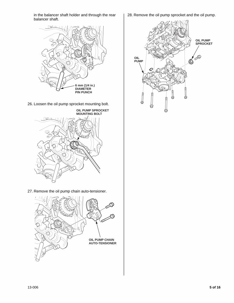
in the balancer shaft holder and through the rear balancer shaft.
26. Loosen the oil pump sprocket mounting bolt.
27. Remove the oil pump chain auto-tensioner.
28. Remove the oil pump sprocket and the oil pump.
6 mm (1/4 in.) DIAMETERPIN PUNCH
OIL PUMP SPROCKETMOUNTING BOLT
OIL PUMP CHAINAUTO-TENSIONER
OIL PUMPSPROCKET
OILPUMP
13-006 5 of 16

29. Remove the baffle plate.
30. Lower the vehicle to a comfortable working height, and place a clean shop towel around the cylinder wall to prevent debris from entering the coolant passage.
31. Check the cylinder walls by rubbing your fingernail or a pencil with light pressure perpendicular to any vertical scratches that are in the cylinder bore.
• If your fingernail or pencil does not catch on the scratches, the cylinder block is OK. Go to step 33.
• If your fingernail or pencil catches on the scratches, go to step 32 to continue checking the cylinder block.
BAFFLEPLATE
6 of 16 13-006

32. Remove the piston from the scratched cylinder bore. Inspect the piston skirt for any scratches or damage that corresponds with the scratched cylinder bore.
• If the piston skirt has deep scratches, or is damaged, and corresponds to the position of the bore scratches, replace the engine block. This bulletin no longer applies. You must obtain DPSM authorization and refer online to Engine Removal and Installation to reinstall the engine.
• If the piston skirt has no damage, the cylinder block is OK; go to step 33.
33. Remove the rod caps and the bearings.
NOTE: • Mark each rod cap and its corresponding rod
with the cylinder number.
• The existing markings refer to the size of the big end of the rod, not the number of the cylinder.
34. Use a wooden hammer handle to drive out each of the piston and connecting rod assemblies.
NOTE: Be careful not to damage the cylinder walls or the crankshaft when pushing out the pistons and the connecting rod assemblies.
Half of the number or bar isstamped on the connecting rodand the other half is stamped on the rod cap.
13-006 7 of 16

35. Visually inspect all the connecting rod bearings for signs of damage.
NOTE: If your fingernail catches on a scratch or groove in the bearing, replace it. Pictured are normal reusable rod bearings after about 35,000 miles. Some discoloration is normal and does not require replacement.
36. Measure the diameter of each connecting rod bolt at points A and B.
37. Calculate the difference in diameter between points A and B:
• Point A – Point B = Difference in Diameter
• Difference in Diameter Specification: 0 - 0.1 mm (0.004 in.)
• If the difference in diameter is out of specification, replace the connecting rod bolt.
38. Put on eye protection, then remove the snap rings from both sides of each piston. Start at the cutout in the piston pin bore. Remove the snap rings carefully so they don’t go flying or get lost.
39. Put on gloves, heat the piston and the ends connecting rod to about 158°F (70°C), then remove the piston pin.
NOTE: The old piston, the pin, and the snap rings won’t be reused.
40. Install a new piston pin snap ring on one side of a new piston.
41. Coat the piston pin bore in the piston, the bore in the connecting rod, and the piston pin with new engine oil.
35 mm (1.38 in)
20 mm (0.79 in)
B A
SNAPRING
SNAP RING
8 of 16 13-006
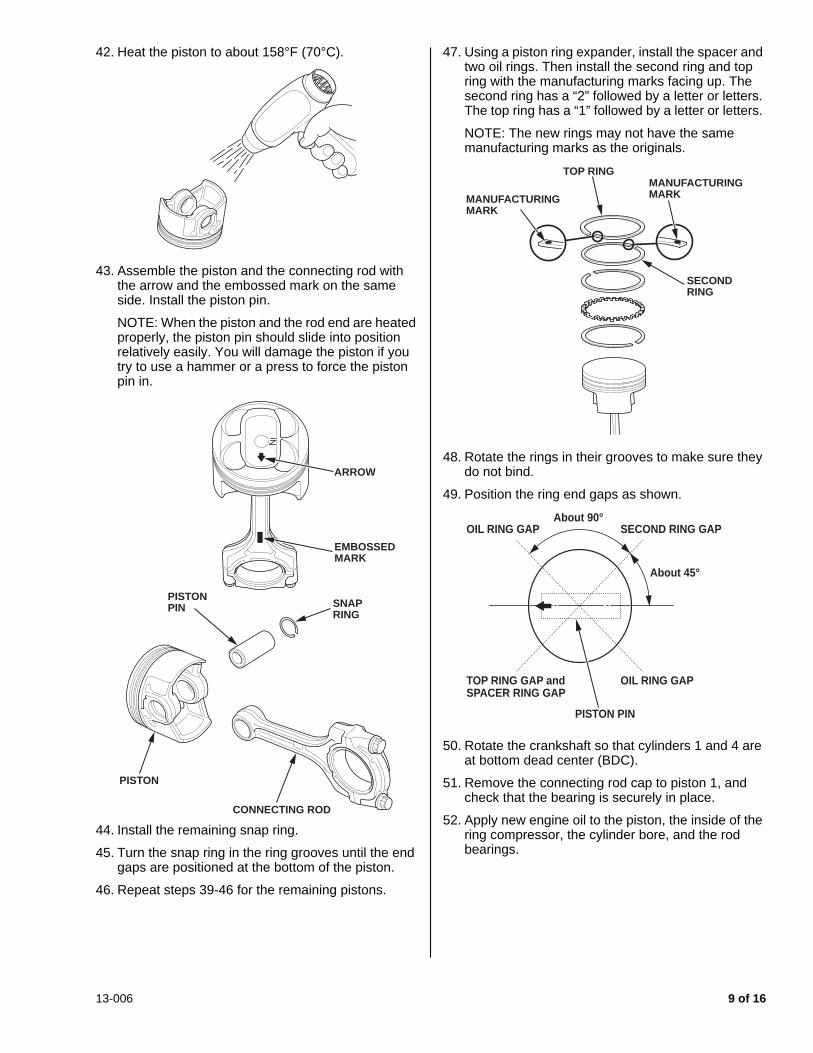
42. Heat the piston to about 158°F (70°C).
43. Assemble the piston and the connecting rod with the arrow and the embossed mark on the same side. Install the piston pin.
NOTE: When the piston and the rod end are heated properly, the piston pin should slide into position relatively easily. You will damage the piston if you try to use a hammer or a press to force the piston pin in.
44. Install the remaining snap ring.
45. Turn the snap ring in the ring grooves until the end gaps are positioned at the bottom of the piston.
46. Repeat steps 39-46 for the remaining pistons.
47. Using a piston ring expander, install the spacer and two oil rings. Then install the second ring and top ring with the manufacturing marks facing up. The second ring has a “2” followed by a letter or letters. The top ring has a “1” followed by a letter or letters.
NOTE: The new rings may not have the same manufacturing marks as the originals.
48. Rotate the rings in their grooves to make sure they do not bind.
49. Position the ring end gaps as shown.
50. Rotate the crankshaft so that cylinders 1 and 4 are at bottom dead center (BDC).
51. Remove the connecting rod cap to piston 1, and check that the bearing is securely in place.
52. Apply new engine oil to the piston, the inside of the ring compressor, the cylinder bore, and the rod bearings.
PISTON
CONNECTING ROD
SNAPRING
PISTONPIN
EMBOSSEDMARK
ARROW
TOP RING
SECONDRING
MANUFACTURINGMARKMANUFACTURING
MARK
OIL RING GAPAbout 90°
SECOND RING GAP
PISTON PIN
OIL RING GAP
About 45°
TOP RING GAP andSPACER RING GAP
13-006 9 of 16
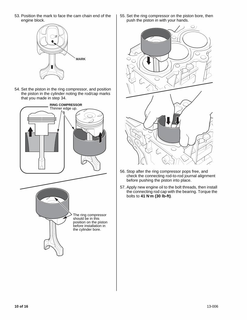
53. Position the mark to face the cam chain end of the engine block.
54. Set the piston in the ring compressor, and position the piston in the cylinder noting the rod/cap marks that you made in step 34.
55. Set the ring compressor on the piston bore, then push the piston in with your hands.
56. Stop after the ring compressor pops free, and check the connecting rod-to-rod journal alignment before pushing the piston into place.
57. Apply new engine oil to the bolt threads, then install the connecting rod cap with the bearing. Torque the bolts to 41 N.m (30 lb-ft).
MARK
RING COMPRESSORThinner edge up.
The ring compressorshould be in thisposition on the pistonbefore installation in the cylinder bore.
10 of 16 13-006

58. Tighten the connecting rod bolts an additional 120°.
NOTE: If you tightened a rod bolt beyond the specified angle, remove it and repeat steps 58 and 59. Do not loosen the bolt back to the specified angle.
59. Repeat steps 48 thru 59 for piston number 4.
60. Rotate the crankshaft so that cylinders 2 and 3 are at bottom dead center (BDC).
61. Repeat steps 48 thru 59 for piston number 2 and 3.
62. Rotate the crankshaft several times after all connecting rods have been installed to ensure that nothing is binding.
63. Install the baffle plate, and torque the bolts to 12 N.m (8.7 lb-ft).
64. Place the No. 1 piston at top dead center (TDC). Make sure the mark lines up with the pointer.
NOTE: The other pointer is not used.
65. Align the dowel pin on the rear balancer shaft with the mark on the oil pump.
66. To hold the rear balancer shaft, insert the 6 mm (1/4 in.) diameter long pin punch into the maintenance hole in the balancer shaft holder and through the rear balancer shaft.
67. Turn the oil pump auto-tensioner plate counterclockwise to release the lock, then push the auto-tensioner arm, and set the first cam to the first edge of the rack. Insert a 3.0 mm (7/64 in.) diameter pin into the hole.
NOTE: If the chain tensioner is not set up as described, the tensioner will be damaged.
120°
TDC MARK
POINTER
UNUSEDPOINTER
DOWEL PINMARK
6 mm LONGPIN PUNCH
PLATEHOLE
OIL PUMP CHAINAUTO-TENSIONER ARM
FIRST CAM
RACK
3.0 mm (7/64 in.)DIAMETER PIN
13-006 11 of 16

68. Apply new engine oil to the threads of the oil pump mounting bolts and the oil pump sprocket mounting bolt, then loosely install the oil pump with a new O-ring.
69. Torque the oil pump mounting bolts to 44 N.m (33 lb-ft).
70. Install the engine oil pump chain.
• Set the crankshaft to top dead center (TDC). Align the TDC mark on the crankshaft sprocket with the pointer on the engine block.
• Install the oil pump chain on the crankshaft sprocket with the colored link plate aligned with the TDC mark on the crankshaft sprocket.
• Set the oil pump chain on the oil pump chain sprocket with the punch mark aligned with the center of the colored link plates, then install the oil pump chain sprocket to the oil pump.
• Apply new engine oil to the threads of the oil pump sprocket mounting bolt, then install it and torque it to 44 N.m (33 lb-ft).
71. Install the oil pump chain auto-tensioner, and torque the bolts to 12 N.m (8.7 lb-ft).
72. Remove the 6 mm (1/4 in.) diameter long pin punch.
OIL PUMP CHAINAUTO-TENSIONER
OIL PUMPMOUNTING BOLTS10 x 1.25 mm44 N.m (33 lb-ft)
OILPUMP
O-RINGReplace.
8 x 1.25 mm22 N.m (16 lb-ft)
OIL PUMPSPROCKETMOUNTING BOLT10 x 1.25 mm44 N.m (33 lb-ft)
6 x 1.0 mm12 N.m(8.7 lb-ft)
6 mm DIAMETERPIN PUNCH
OIL PUMPSPROCKET
POINTER ON THEENGINE BLOCK
CRANKSHAFTSPROCKET
TDC MARK
COLORED LINK PLATE
TDC MARK
OIL PUMPSPROCKETMOUNTING BOLT44 N.m (33 lb-ft)OIL PUMP
CHAIN GUIDE
OIL PUMPCHAIN SPROCKET
OIL PUMPCHAIN GUIDE BOLT12 N.m (8.7 lb-ft)
COLORED LINK PLATES
PUNCHMARK
6 mm LONGPIN PUNCH
12 of 16 13-006

73. Remove the 3.0 mm pin from the oil pump chain auto-tensioner.
74. Remove all of the old liquid gasket from the oil pan mating surfaces, the bolts, and the bolt holes.
75. Clean and dry the oil pan mating surfaces.
76. Apply liquid gasket, P/N 08717-0004, 08718-0003, or 08718-0009, to the engine block mating surface of the oil pan and to the inside edge of the threaded bolt holes. Install the component within 5 minutes of applying the liquid gasket.
NOTE: • Apply a 2.5 mm (0.098 in) diameter bead of liquid
gasket along the broken line.• If more than 5 minutes have passed after
applying the liquid gasket, remove the old liquid gasket and residue, then reapply new liquid gasket.
• Do not apply any sealant where the cam chain case is installed because the sealant will dry before you can reinstall the case.
77. Install the oil pan to the engine block.
78. Tighten the bolts in three steps. In the final step, torque all bolts, in sequence, to 12 N.m (9 lb-ft).
NOTE: • Wait at least 30 minutes after installing the cam
chain case before filling the engine with oil.• Do not run the engine for at least 3 hours after
installing the oil pan.
79. Install a new oil filter.
80. Reinstall the clutch case cover and torque the bolts to 12 N.m (8.7 lb-ft). Reinstall the two bolts securing the oil pan to the transmission and torque them to 64 N.m (47 lb-ft).
81. Reinstall the cylinder head with a new gasket.
• Measure the diameter of each cylinder head bolt at point A and point B.
• If either diameter is less than 10.8 mm (0.417 in), replace the cylinder head bolt.
• Apply new engine oil to the threads and under the bolt heads of all cylinder head bolts.
3.0 mm (7/64 in.)DIAMETER PIN
LIQUID GASKET 2.5 mm(0.098 in.)
No sealant here. This areawill be sealedafter the chaincover is installed.
16 13 9 5 1 3 7
610
11
15
17
128421418 610
11
14
15
1284213
73159
These threebolts will beinstalled afterthe chain coveris installed.
B
50 mm (1.97 in)
45 mm (1.77 in)
A
13-006 13 of 16

• Torque the cylinder head bolts in sequence to 39 N.m (20 lb-ft). When using a preset click-type torque wrench, be sure to tighten slowly and do not overtighten. If a bolt makes any noise while you are torquing it, loosen the bolt and retighten it from the first step.
• After torquing, tighten all cylinder head bolts in two steps (90° per step) using the sequence shown above. If you are using a new cylinder head bolt, tighten the bolt an extra 90°.
NOTE: Remove the cylinder head bolt if you tightened it beyond the specified angle, and go back to the second bullet to remeasure the bolt. Do not loosen it back to the specified angle.
82. Reinstall the rocker arm assembly and the cam shafts.
83. Reinstall the cam chain.
84. Apply liquid gasket to the oil pan where it meets the cam chain case and to the inside edge of the threaded bolt holes. Install the cam chain case within 5 minutes of applying the liquid gasket.
85. Install the cam chain cover.
86. Adjust the valves.
87. Reinstall the cylinder head cover.
88. Reinstall the connecting pipe.
89. Reinstall the upper radiator hose, the heater hoses, and the water bypass hose.
90. Reinstall the EVAP canister purge valve bracket.
91. Reconnect the four fuel injectors, the engine mount control solenoid connector, and the ground cables.
92. Reconnect the fuel feed hose and the quick-connect fitting cover.
93. Reconnect the EVAP canister hose.
94. Reinstall the warm up TWC with new gaskets and nuts.
95. Install the intake manifold using new gaskets.
610 84 2
7 35 91
FIRST STEP
SECOND STEPTHIRD STEP(New bolt)
3.5 mm(0.138 in)
LIQUID GASKET
CAM CHAIN CASESPACER
OIL PAN BOLTS12 N.m (8.7 lb-ft) CHAIN
CASE BOLTS12 N.m (8.7 lb-ft)
14 of 16 13-006

96. Reinstall the drive belt.
97. Fill the engine with coolant.
98. Reinstall the strut brace (if equipped), and torque the bolts to 22 N.m (16 lb-ft).
99. Fill the engine with oil.
100. Do the battery terminal reconnection procedure.
101. Crank the engine for about 5 seconds to prime the engine with oil pressure before plugging in the ignition coils.
102. Reconnect the four ignition coils.
103. Do the idle learn procedure.
ORDERING PISTONSEvery engine has some combination of A- and B-sized pistons. You can determine the sizes and their locations in the block by inspecting the markings on the timing chain end of the engine block or by looking at the pistons.
If you look at the piston, the pistons have identifiers; “A” pistons are unmarked; “B” pistons are marked with a “B”. Make sure you order the appropriate number of each piston size before starting work.
13-006 15 of 16

16 of 16 13-006