Embed Size (px)
Citation preview

CUSTOMER INFORMATION: The information in this bulletin is intended for use only by skilled technicians who have the proper tools, equipment, and training to correctly and safely maintain your vehicle. These procedures should not be attempted by “do-it-yourselfers,” and you should not assume this bulletin applies to your vehicle, or that your vehicle has the condition described. To determine whether this information applies, contact an authorized Honda automobile dealer.
© 2016 American Honda Motor Co., Inc. – All Rights Reserved Page 1 of 29
Service Bulletin 12-087
April 20, 2016 47913-01614 Version 5
Warranty Extension: Sticking Rings Resulting in High Engine Oil Consumption Supersedes 12-087, Sticking Rings Resulting in Unusually High Engine Oil Consumption, dated June 13, 2015; see Revision Summary
AFFECTED VEHICLES
Year Model Trim VIN Range 2008–11 Accord L4 ALL Check the iN VIN status eligibility
REVISION SUMMARY
Under REPAIR PROCEDURE, a torque value was updated.
BACKGROUND
American Honda is extending the warranty coverage on the Piston Rings and Pistons for 2008-11 Accord L4 to 8 years from the original date of purchase or 125,000 miles, whichever comes first.
The warranty extension does not apply to any vehicle that has ever been declared a total loss or sold for salvage by a financial institution or insurer, or has a branded, or similar tittle under any state’s law. To check for vehicle eligibility, you must do a VIN status inquiry.
CUSTOMER NOTIFICATION
Owners of affected vehicles will receive a notification of this warranty extension.
Do an iN VIN status inquiry to make sure the vehicle is shown as eligible.
SYMPTOM
The engine oil level is low on the dipstick, and the oil warning light may come on in rare high oil consumption situations.
POSSIBLE CAUSES
Under certain specific circumstances the engine may create deposits on the oil control rings, which may lead to increased oil consumption when all of the following conditions occur simultaneously on a regular and prolonged basis:
• The engine is cold (not warmed up to operating temperature)
• Hard acceleration while the engine is cold
• The fuel used has an unusually high concentration of particles - Honda recommends using Top Tier gas that contains detergents to prevent deposits. For more information about Top Tier gas, go to www.toptiergas.com.
All these conditions happening at the same time is rare, but if they do, deposits may form over years of driving. If the oil control rings begin to stick because of the deposits, the customer may subsequently complain about excessive oil consumption.
Page 2 of 29
CORRECTIVE ACTION
Do the procedure under DIAGNOSIS and based on your results, replace all of the engine pistons and piston rings if necessary. Service Advisor: Talk to the customer about the many factors contributing to oil consumption. Remind him or her that with less frequent service intervals for modern engines, it’s not uncommon to add oil between services. Therefore, it’s a good idea to check the engine oil regularly (as recommended in the owner’s manual) and add oil as necessary.
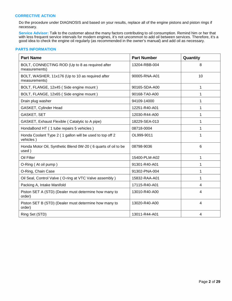
PARTS INFORMATION
Part Name Part Number Quantity BOLT, CONNECTING ROD (Up to 8 as required after measurements)
13204-RBB-004 8
BOLT, WASHER, 11x176 (Up to 10 as required after measurements)
90005-RNA-A01 10
BOLT, FLANGE, 12x45 ( Side engine mount ) 90165-SDA-A00 1
BOLT, FLANGE, 12x65 ( Side engine mount ) 90168-TA0-A00 1
Drain plug washer 94109-14000 1
GASKET, Cylinder Head 12251-R40-A01 1
GASKET, SET 12030-R44-A00 1
GASKET, Exhaust Flexible ( Catalytic to A pipe) 18229-SEA-013 1
HondaBond HT ( 1 tube repairs 5 vehicles ) 08718-0004 1
Honda Coolant Type 2 ( 1 gallon will be used to top off 2 vehicles )
OL999-9011 1
Honda Motor Oil, Synthetic Blend 0W-20 ( 6 quarts of oil to be used )
08798-9036 6
Oil Filter 15400-PLM-A02 1
O-Ring ( At oil pump ) 91301-R40-A01 1
O-Ring, Chain Case 91302-PNA-004 1
Oil Seal, Control Valve ( O-ring at VTC Valve assembly ) 15832-RAA-A01 1
Packing A, Intake Manifold 17115-R40-A01 4
Piston SET A (STD) (Dealer must determine how many to order)
13010-R40-A00 4
Piston SET B (STD) (Dealer must determine how many to order)
13020-R40-A00 4
Ring Set (STD) 13011-R44-A01 4

Page 3 of 29
TOOL INFORMATION
Part Name Part Number Quantity Camshaft Lock Pin Set 07AAB-RWCA120 1
Crank Pulley Holder 07AAB-RJAA100 1
Handle 6-25-660L 07JAB-001020B 1
Engine Hanger AART1256 1
Gasket Remover/Pan Separator LIL50190 1
Piston Ring Expander Snap-On PRS8 or equivalent
1
Piston Ring Compressor SCP1287 or equivalent 1
1/2 in. Drive Torque Angle Gauge BLMBLDAG001 or TA360 1
NOTE: These Items can be purchased through the Honda Tool & Equipment Program 888-424-6857.
WARRANTY CLAIM INFORMATION
Operation Number
Description Flat Rate Time Failed Part Number
1111BF Replacing all pistons and piston rings
10.0 hrs 13011-R44-A01
Defect Code: 5X100 Symptom Code: JN900 Skill Level: Repair Technician
DIAGNOSIS
1. Do an engine oil consumption test. Refer to the Job Aid Engine Oil Consumption Test. 2. Review the results of the engine oil consumption test. • Based on the test results, if the engine is consuming an unusually high amount of oil, contact your DPSM for
approval, then go to REPAIR PROCEDURE. • Based on the test results, if the engine is consuming a normal amount of engine oil, the vehicle is OK. Explain to the
customer that the vehicle is OK, and that the consumption of oil is within a normal range.
NOTE: Remind the customer to regularly check the engine oil level every time they fill the fuel tank. Modern engines require less frequent oil changes, which may impact the amount of oil used between oil changes.
REPAIR PROCEDURE
This procedure is an outline form that you can also use as a checklist for the repair. For details on the procedures noted, refer to the appropriate service manual, or view them online.
• Engine Oil Replacement
• Battery Terminal Disconnection and Reconnection
• Fuel Pressure Relieving
• Coolant Replacement
• Drive Belt Removal/Installation
• Intake Manifold Removal and Installation
• Warm Up TWC Removal/Installation
Note: Disconnect TWC at the A-pipe at TWC.

Page 4 of 29
• Fuel Line/Quick-Connect Fitting Removal
• Cylinder Head Removal
• Cam Chain Removal
• Rocker Arm Assembly Removal
• Valve Adjustment
• Oil Pan Installation
• ECM Idle Learn Procedure
NOTE:
• Before starting work, make sure to order the correct number of “A” and “B” pistons. Refer to ORDERING PISTONS on page 29 of this bulletin.
• Use fender covers to avoid damaging painted surfaces. • To avoid damaging the wires and terminals, unplug the wiring connectors carefully while holding the
connector portion. • To avoid damaging the cylinder head, wait until the engine coolant temperature drops below 100°F (38°C)
before loosening the cylinder head bolts. If needed, connect the HDS to the DLC, and monitor ECT SENSOR 1.
• Mark all wiring and hoses to avoid misconnection. Also, be sure that they do not contact any other wiring or hoses, or interfere with any other parts.
1. Make sure that Service Bulletin 11-049, Product Update: Software Update to Improve Fuel Injector and VTC Timing
is complete by checking the iN VIN status. NOTE: If you do not confirm software update has been completed, your warranty claim could be debited
2. Put the vehicle on a lift.
3. Relieve the fuel pressure.
4. Do the battery terminal disconnection procedure.
5. Drain the engine oil.
6. Remove the strut brace (if equipped).
7. Drain the engine coolant.
NOTE: Use a clean container to recover coolant for re-use.
8. Remove the drive belt.
Page 5 of 29
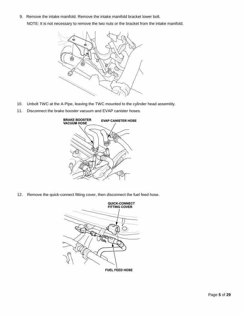
9. Remove the intake manifold. Remove the intake manifold bracket lower bolt.
NOTE: It is not necessary to remove the two nuts or the bracket from the intake manifold.
10. Unbolt TWC at the A-Pipe, leaving the TWC mounted to the cylinder head assembly.
11. Disconnect the brake booster vacuum and EVAP canister hoses.
12. Remove the quick-connect fitting cover, then disconnect the fuel feed hose.

Page 6 of 29
13. Disconnect the four fuel injector connectors, the engine mount control solenoid valve connectors, and disconnect the ground cables.
14. Remove the four bolts securing the EVAP canister purge valve bracket.

Page 7 of 29
15. Disconnect the radiator hoses and the heater hoses. Disconnect the ATF warmer bypass hose (if equipped) NOTE: The second radiator hose is connected to the thermostat and is not shown.
16. Remove the two bolts securing the connecting hose. Disconnect the water bypass hose.

Page 8 of 29
17. Remove the front cam chain cover and the cam chain.
18. Use zip ties to hold the four intake rocker assemblies together to ease re-installation.

Page 9 of 29
19. To prevent damage to the camshafts, loosen the bolts, in sequence, two turns at a time. Remove the camshaft holder bolts, Remove the rocker arm assembly and both cam shafts.
NOTE: Bolt #1 is not on all engines.
20. To prevent warpage, loosen the bolts in sequence 1/3 turn at a time, repeat the sequence until all the bolts are loosened. Remove the cylinder head bolts.
Page 10 of 29
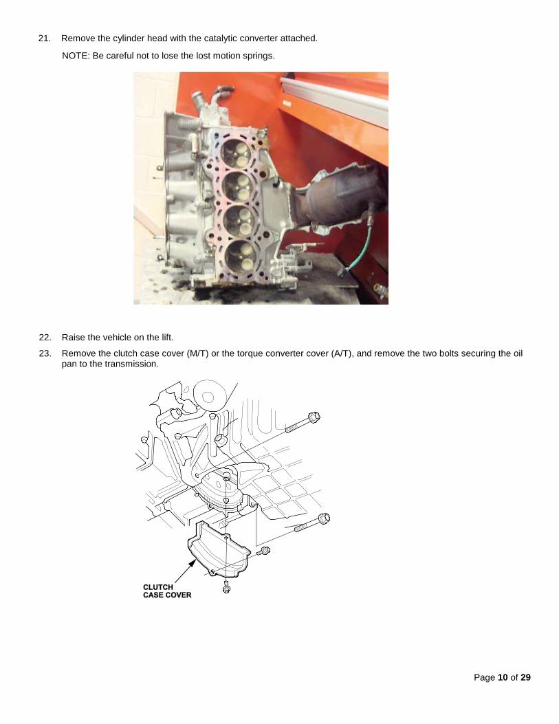
21. Remove the cylinder head with the catalytic converter attached.
NOTE: Be careful not to lose the lost motion springs.
22. Raise the vehicle on the lift.
23. Remove the clutch case cover (M/T) or the torque converter cover (A/T), and remove the two bolts securing the oil pan to the transmission.

Page 11 of 29
24. With A/T: Remove the shift cable cover.
25. Remove the bolts securing the oil pan.
26. Using the pan separator, separate the oil pan from the engine block in the indicated areas, and remove the oil pan.

Page 12 of 29
27. To hold the balance shaft, insert a 6 mm (1/4in.) diameter long pin punch into the maintenance hole in the balance shaft holder and through the rear balancer shaft.
28. Remove the cam chain and oil pump chain auto-tensioner.

Page 13 of 29
29. Loosen the oil pump sprocket mounting bolt.
30. Remove the oil pump sprocket and the oil pump.
Page 14 of 29
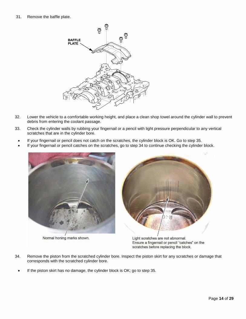
31. Remove the baffle plate.
32. Lower the vehicle to a comfortable working height, and place a clean shop towel around the cylinder wall to prevent debris from entering the coolant passage.
33. Check the cylinder walls by rubbing your fingernail or a pencil with light pressure perpendicular to any vertical scratches that are in the cylinder bore.
• If your fingernail or pencil does not catch on the scratches, the cylinder block is OK. Go to step 35. • If your fingernail or pencil catches on the scratches, go to step 34 to continue checking the cylinder block.
34. Remove the piston from the scratched cylinder bore. Inspect the piston skirt for any scratches or damage that corresponds with the scratched cylinder bore.
• If the piston skirt has no damage, the cylinder block is OK; go to step 35.

Page 15 of 29
• If the piston skirt has deep scratches, or is damaged, and corresponds to the position of the bore scratches, replace the engine block. This bulletin no longer applies. You must obtain DPSM authorization and refer online to Engine Removal and Installation to reinstall the engine.
35. Remove the rod caps and the bearings.
NOTE:
• Mark each rod cap and its corresponding rod with the cylinder number. • The existing markings refer to the size of the big end of the rod, not the number of the cylinder.
36. Use a wooden hammer handle to drive out each of the piston and connecting rod assemblies.
NOTE: Be careful not to damage the cylinder walls or the crankshaft when pushing out the pistons and the connecting rod assemblies.

Page 16 of 29
37. Visually inspect all the connecting rod bearing for signs of damage.
NOTE: If your fingernail catches on a scratch or groove in the bearing, replace it. Pictured are normal reusable rod bearings after about 35,000 miles. Some discoloration is normal and does not require replacement.
38. Measure the diameter of each connecting rod bolt at points A and B.
39. Calculate the difference in diameter between points A and B:
• Point A – Point B = Difference in Diameter • Difference in Diameter Specification: 0 - 0.1 mm (0.004 in.) • If the difference in diameter is out of specification, replace the connecting rod bolt.

Page 17 of 29
40. Put on eye protection, then remove the snap rings from both sides of each piston. Start at the cutout in the piston pin bore. Remove the snap rings carefully so they don’t go flying or get lost.
41. Put on gloves, heat the piston and the ends connecting rod to about 158°F (70°C), then remove the piston pin.
NOTE: The old piston, the pin, and the snap rings won’t be reused.
42. Install a new piston pin snap ring on one side of a new piston.
43. Coat the piston pin bore in the piston, the bore in the connecting rod, and the piston pin with new engine oil.
Page 18 of 29
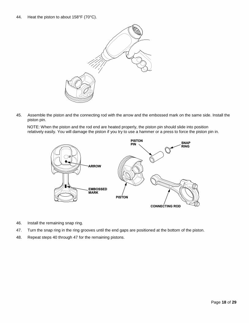
44. Heat the piston to about 158°F (70°C).
45. Assemble the piston and the connecting rod with the arrow and the embossed mark on the same side. Install the
piston pin.
NOTE: When the piston and the rod end are heated properly, the piston pin should slide into position relatively easily. You will damage the piston if you try to use a hammer or a press to force the piston pin in.
46. Install the remaining snap ring.
47. Turn the snap ring in the ring grooves until the end gaps are positioned at the bottom of the piston.
48. Repeat steps 40 through 47 for the remaining pistons.

Page 19 of 29
49. Using a piston ring expander, install the spacer and two oil rings. Then install the second ring and top ring with the manufacturing marks facing up. The second ring has a “2” followed by a letter or letters. The top ring has a “1” followed by a letter or letters.
NOTE: The new rings may not have the same manufacturing marks as the originals.
50. Rotate the rings in their grooves to make sure they do not bind.
51. Position the ring end gaps as shown.
52. Rotate the crankshaft so that cylinders 1 and 4 are at bottom dead center (BDC).
53. Remove the connecting rod cap to piston 1, and check that the bearing is securely in place.
54. Apply new engine oil to the piston, the inside of the ring compressor, the cylinder bore, and the rod bearings.
Page 20 of 29
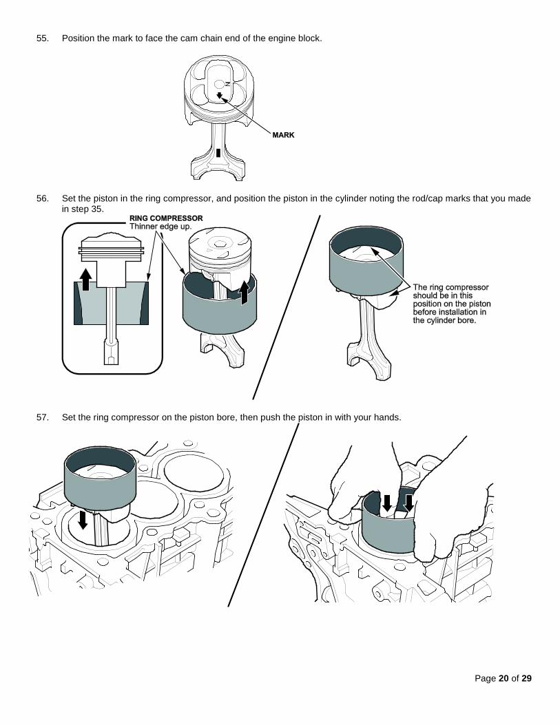
55. Position the mark to face the cam chain end of the engine block.
56. Set the piston in the ring compressor, and position the piston in the cylinder noting the rod/cap marks that you made in step 35.
57. Set the ring compressor on the piston bore, then push the piston in with your hands.

Page 21 of 29
58. Stop after the ring compressor pops free, and check the connecting rod-to-rod journal alignment before pushing the piston into place.
59. Apply new engine oil to the bolt threads, then install the connecting rod cap with the bearing. Torque the bolts to 41 N·m (30 lb-ft).
60. Tighten the connecting rod bolts an additional 120°.
NOTE: If you tighten a rod bolt beyond the specified angle, remove it and repeat steps 58 and 59. Do not loosen the bolt back to the specified angle.
61. Repeat steps 49 through 60 for piston number 4.
62. Rotate the crankshaft so that cylinders 2 and 3 are at bottom dead center (BDC).
63. Repeat steps 49 through 60 for piston number 2 and 3.
64. Rotate the crankshaft several times after all connecting rods have been installed to ensure that nothing is binding.
65. Install the baffle plate, and torque the bolts to 12 N·m (8.7 lb-ft).
66. Set the crankshaft to top dead center (TDC). Align the TDC mark (A) on the crankshaft sprocket with the pointer (B) on the engine block.
67. Apply new engine oil to the threads of the oil pump mounting bolts (B) and the oil pump sprocket mounting bolt (C), then loosely install the oil pump (D) with a new O-ring (E).

Page 22 of 29
68. Torque the oil pump mounting bolts and the oil pump sprocket mounting bolt according to figure shown.
69. Align the dowel pin (A) on the rear balancer shaft with the mark (B) on the oil pump.
70. Install the oil pump chain on the crankshaft sprocket with the colored link plate (A) aligned with the TDC mark (B) on the crankshaft sprocket.

Page 23 of 29
71. Set the oil pump sprocket on the oil pump chain with the punch mark aligned with the center of the colored link plates, then install the oil pump chain sprocket to the oil pump.
• Apply new engine oil to the threads of the oil pump sprocket mounting bolt, then install it and torque it to 44 N·m (33 lb-ft).
72. Install the oil pump chain auto-tensioner, and torque the bolts to 12 N·m (8.7 lb-ft).
73. Remove the 6 mm (1/4 in.) diameter long pin punch.
74. Remove the 3.0 mm pin from the oil pump chain auto-tensioner.
75. Remove all of the old liquid gasket from the oil pan mating surfaces, the bolts, and the bolt holes.
76. Clean and dry the oil pan mating surfaces.

Page 24 of 29
77. Apply liquid gasket, P/N 08718-0004, 08718-0003, or 08718-0009, to the engine block mating surface of the oil pan and to the inside edge of the threaded bolt holes. Install the component within 5 minutes of applying the liquid gasket.
NOTE:
• Apply a 2.5 mm (0.098 in) diameter bead of liquid gasket along the broken line. • If more than 5 minutes have passed after applying the liquid gasket, remove the old liquid gasket and residue,
then reapply new liquid gasket. • Do not apply any sealant where the cam chain case is installed because the sealant will dry before you can
reinstall the case.
78. Install the oil pan to the engine block.
79. Tighten the bolts in three steps. In the final step, torque all bolts, in sequence, to 12 N·m (9 lb-ft). NOTE:
• Wait at least 30 minutes after installing the cam chain case before filling the engine with oil. • Do not run the engine for at least 3 hours after installing the oil pan.
80. Install a new oil filter. 81. Reinstall the clutch case cover and torque the bolts to 12 N·m (8.7 lb-ft). Reinstall the two bolts securing the oil pan
to the transmission and torque them to 64 N·m (47 lb-ft).

Page 25 of 29
82. With A/T: Reinstall the shift cable cover, and torque the bolts to 12 N·m (9.0 lb-ft).
83. Reinstall the cylinder head with a new gasket.
• Measure the diameter of each cylinder head bolt at point A and point B. • If either diameter is less than 10.8 mm (0.417 in), replace the cylinder head bolt. • Apply new engine oil to the threads and under the bolt heads of all cylinder head bolts.
• Torque the cylinder head bolts in sequence to 39 N·m (29 lb-ft). When using a preset click-type torque
wrench, be sure to tighten slowly and do not overtighten. If a bolt makes any noise while you are torquing it, loosen the bolt and retighten it from the first step.
• After torqueing, tighten all cylinder head bolts in two steps (90° per step) using the sequence shown above. If
you are using a new cylinder head bolt, tighten the bolt an extra 90°.
NOTE: Remove the cylinder head bolt if you tightened it beyond the specified angle, and go back to the second bullet to re-measure the bolt. Do not loosen it back to the specified angle.
84. Reinstall the rocker arm assembly and the camshafts.
85. Reinstall the cam chain.

Page 26 of 29
86. Apply liquid gasket to the oil pan where it meets the cam chain case and to the inside edge of the threaded bolt holes. Install the cam chain case within 5 minutes of applying the liquid gasket.
87. Install the cam chain cover.
88. Reinstall crank pulley.
Page 27 of 29
89. Adjust the valve clearance. Refer to the service manual for Valve Clearance Adjustment.
Valve Clearance:
Intake: 0.21 – 0.25 mm (0.0083 – 0.0098 in)
Exhaust: 0.25 – 0.29 mm (0.0098 – 0.0114 in)
Specified Torque (Intake & Exhaust)
7 x 0.75 mm: 14 N·m (1.4 kgf·m, 10 lbf·ft)
Apply new engine oil to the nut threads.
90. Reinstall the cylinder head cover.
91. Reinstall the connecting pipe.
92. Reinstall the upper radiator hose, the heater hoses, and the water bypass hose.
93. Reinstall the EVAP canister purge valve bracket.
94. Reconnect the four fuel injectors, the engine mount control solenoid connector, and the ground cables.
95. Reconnect the fuel feed hose and the quick connect fitting cover.
96. Reconnect the EVAP canister hose.
97. Install new gasket from TWC to A-pipe.
98. Install the intake manifold using new gaskets.
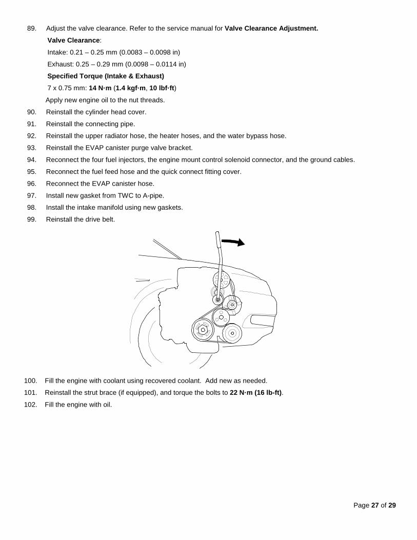
99. Reinstall the drive belt.
100. Fill the engine with coolant using recovered coolant. Add new as needed.
101. Reinstall the strut brace (if equipped), and torque the bolts to 22 N·m (16 lb-ft).
102. Fill the engine with oil.

Page 28 of 29
103. Reinstall right side engine mount
104. Do the battery terminal reconnection procedure.
105. Crank the engine for about 5 seconds to prime the engine with oil pressure before plugging in the ignition coils.
106. Reconnect the four ignition coils.
107. Do the idle learn procedure.
END.

Page 29 of 29
ORDERING PISTONS
Every engine has some combination of A- and B-sized pistons. You can determine the sizes and their locations in the block by inspecting the markings on the timing chain end of the engine block or by looking at the pistons. If you look at the piston, the pistons have identifiers; “A” pistons are unmarked; “B” pistons are marked with a “B”. Make sure you order the appropriate number of each piston size before starting work.

![Page 2 Phone 087 2513126 • 087 2330398 Kenmare News News Feb 2013.pdf · Page 2 Phone 087 2513126 • 087 2330398 Kenmare News Dear Editor, ... wedding album; The wedding [book]](https://img.pdfslide.us/doc/110x75/5b78280a7f8b9a515a8e9ea6/page-2-phone-087-2513126-087-2330398-kenmare-news-feb-2013pdf-page-2-phone.jpg)


![Trito Mati - [087 - 2000]](https://img.pdfslide.us/doc/110x75/577cd7e91a28ab9e789ff5f7/trito-mati-087-2000.jpg)