Embed Size (px)
Citation preview

S E R V I C EUnited States
SALES OFFICESDOMETIC SALES CORP.Zone 12320 Industrial ParkwayElkhart. IN 46515(219) 295.5226
DOMETIC SALES CORP .Zone II2920 Avenue “E” EastArlington, TX 76011(81 7) 649.5726
DOMETIC SALES CORP.Zone III14441 Bonelli St.City of Industry, CA 91746(818 ) 968-9431
Canada
DOMETIC DISTRIBUTION INC866 Langs DriveCambrIdge. OntarioN3H 2N7 Canada(519 ) 653-4390
Edition1
Publication No4528-E/Service
May 1973DSC # 648
REFRIGERATORfor recrea t ional vehicles
R M 2 4 A R M 3 6 CS E R V I C E M A N U A L R M 4 6 R M 4 7
R M 6 6 R M 6 7
When or deri ng SPARE PARTS always state:
MODEL. QUANTITY. PART NUMBER. DESCRIPTION
For electric details also:
VOLTAGE. WATTAGE
1 R M 7 6 R M 7 7 1
Diagnostic Service Manuals

2
Service Instructions for Domtic Absorption Refrigerators
The absorption refrigerators described in this manual are primarily for installationin recreational vehicles.
Since the vehicles in which the refrigerator s are located may be driven to remotecamp sites wh ere electrical power is not available, the refrigerator5 have b e e ndesigned co operate by mean s o f b o t t l e p r o p a n e o r b u t a n e g a s a s we ll a s b ye l e c t r i c i ty 12/110V.
These Service Instructions cover the Dometic Models RM24, RM36C,RM46, RM47, RM66, RM67, RM76, RM77.
LIST OF CONTENTS
Description Pag
ECHNIGU FE AT UR ES
Ca bine t es, equipment . .._ . . . . . . . . . . . . . . . . . . . . . . . 3
INSTALLATION INSTRUCTIONS
General instructions . ____ . . . . . . . . . . . 4
Ventilation___ . . . . . . . . . . . . . . . . . . . . . . . 5
Gas connections ____ ____ . . . . . . . . . . . . . . . 5
Electrical connections___________..______ 5
Approved installations 7
Me asure ments ... ____ . . . . . . . . . . . . . . . . . . . . 10
Ca binet A d j u s t m e n t s
To change the door panel _ . _ ____ _____ . . . . 13
Replacement of door gasket___.________.. 15
Replacement of evaporator door and gasket. 16
Reversing outer door__ . . .. . . . . . . . . . . . . . ___ 18
THE AB SORPTION REFRIGRATOR SYSTE M
Sealed system constructions . . _ _ _ _ . . . . . . . 20
Operating analysis for cooling unit . . . . . . 22
Cooling unit replacement . . . . . . . . . . . . . . . . . 23
GAS/ELECTRIC EQUIPMENT
Gas equipment for RM24 ..... . . . . . . . . . . .. . . 28
Dual electri c equipment for RM24 . . . . . . . . 29
C a r / e l e c t r i c equ ipment for RM36C,RM46, RM47, RM66, RM67 , RM76, RM77... _ _ _ _ 30
AS OPERATION - FU NCTIO NAL PARTS
Termostat - replacment ___ . . . . . . . . . . . . . . 32
The gas burner ...... . . . . . . . . . .. . . . . . . . . . . . . . . 33
Flue system . . . . . . . . . . . . . . . ........ . . . . . . . . . 34
Thermo flame failure device . . . . . . . . . . . . . . . 35
Description
ELECTRIC OPERATION - FUNCTIONAL PARTS
Re place ment of heater_______________.__.
Wiring dia gr ams ................................
PRESSURE MEASURING DEVICES . . . . . . . . . . . . . . .
OPERATING RE COMMENDA TIONS
Gas operation _______ _____ _______ _____
Electric operation . . . . . . . . . . . . . . . . .
MAINTENANCE
Levelling _________ . . . . . . . . . . . . . . . . . . 42
T e m p e r a t u r e C o n t r o l ( t h e r m o s t a t ) . . . . 4 2
The themostat capillary tube . . . . . . . . . . 42
Storing food in the refrigerator_______. 43
Cleaning _____ . . . . . ______ . . . . . . . . . . . . . . . 43
Ice cubes___________ ____ ______________ 43
Travel latch ____ ____ _____ . . . . . . . . . . . . . . . 43
Door seal_ . . . . . . ___ ______ ______ ____ ___ 43
Odors inside the refrigerator . . . . . . . . . . . . 44
Odors from fumes 44
Flame blows out . . . . . ........ . ____ ________ 44
Flint l ighter_______ . . . . . . . . . . . . . . . . . . 44
Piezo lighter ____________ _ ____ _________ 45
DIAGNOSIS
Trouble shooting - electric operatedrefrigerators _____ __ . . . . . . . . . . . . . . . . . . .
Troub le shooting - gas operatedrefrigerators_______ . . . . . . . . . . . . . . . ......
Failed refrigerating unit_____.. ._____._
Operation analysis for electricoperated refrigerators . . . . . . . . . . . . . . . . . . . .
Operation analysis for LP gasoperated refrigerators . . . . . . . . . . . . . . . . . .
Periodic maintenance . .
37
38
39
40
41
47
48
49
50
51
52

1. TECHNICAL FEATURES
RM24
The cabinet has a so called “Full Finish Casing” and can be used freestanding orbuilt-in. RM24 is a compact refrigerator, ideal for campers, fitted with front frameand seals.
This refrigerator is fitted with right-hand door with change over facility to left-hand door and exchangeable front door panel in an aluminium framed door.
Exchange can be made without the removal of the door. A full range of equipment isavailable operated from the rear of the cabinet. A blow-out protection flue isfitted as standard to assist in maintaining flame stability under adverse windconditions. A sealing frame is fitted around the cabinet for building-in p u r p o s e s ,
The refrigerator has one basic casing which is Foamed in place with a lining.Insulation material polyurethane.
The construction of the door, complete, is an aluminium extruded door framefoamed in place with the door pan and magnetic gasket.
Equipment
Fool-proof electric/gas interlock system. Thermo-electric flame failure device.Flint lighting system. The electric and the gas thermostats are of the EnglishRanco-make .
The gas/e1 controls are located at the rear of the refrigerator and are acccssiolethrough the service door in the wall, when installed in a vehicle.
Version
Gas/110 volts A.C. and 12 volts D.C.
RM36C, RM46, RM47, RM66, RM67, RM76, RI.177
Cabinet
Thin wall polyurethane insulation. All models except RM76 and RM77 have foamed inplace insulation. RM76 and RM77 are foamed against mould.
Lining of vacuum-foamed ABS plastic, except RM36C, which has a lining of injectionmoulded SB plastic.
Distinct stop for evaporator door at opening, RM46, RM47, R M 6 6 and R M 6 7
Cabinet shelf with hinge for big bottles,
The shelves run in grooves and will not move during transport of the vehicle.
Freezer compartments are, of aluminiurn sheet, except RM36C, where it is an injectiormoulded part of the lining.
Accessible control panel inside the fresh food compartment.

4
Door
All models will be delivered with right hand door hinging, but it is possible forthe customer to change the door hinging from right to left hand.
Replacement of door panel is possible without removing the door. Only the sideprofile of the door frame has to be removed.
Equipment
All models incorporate a thermo-electric flame failure safety device and a piezolighting system.
The equipment for electric and gas operation is located at the rear of the cabinetand manipulated from inside the cabinet.
The gas shut-off valve and the electric voltage-change switch are interlocked sothat both methods of operation cannot be inadvertently used at the same time.
The electric and gas thermostats are of the Ranco-make.
Version
All models will be available with combination equipments for LP gas and 110 voltsA.C. or LP gas/110 volts A.C. and 12 volts D.C.
2. INSTALLATION INSTRUCTIONS
For LP-gas and electric operation in Motor Homes and Recreational Vehicles.
General instructions
The refrigerators outlined herein have been design certified under ANS 221.19Refrigerators by the American Gas Association for installation in a mobile home orrecreational vehicle and are approved by the Canadian Gas Association.
The certifications are, however, contingent on the installation being made inaccordance with the following instructions,
The installation must conform with:
In U.S.A.:
1.
2 .
3.
4.
In
1.
2 .
Installation of Gas Appliance and Gas Piping, 221.30 - 1964.
Mobile Homes A 119.1 - 1969.
Recreational Vehicles A 119.2 - 1970. The unit must be electrically grounded inaccordance with the National Electrical Code ANSI CI - 1968, when installed ifan external alternating current electrical source is util ized.
Any applicable local code,
Canada:
C S A Standard B 149. “Installation Code for Gas Burning Appliances and Equipment”
C S A Standard B 210.1/Z 240.4. “Gas equipped recreational vehicles and mobilehomes”

5
Ventilation
The installation shall be made in such a manner as to separate the combustion systemfrom the living space of the recreational vehicle. Openings for air supply or forventing of combustion products shall have a minimum dimension of not less thanl/4 inch.
Approved installation requires one lower fresh air intake and one upper exhaustvent. The accessory ventilation kits shown in these instructions have been testedand approved for use with the refrigerator models identified. Their use is recommended, and when employed, the ventilation kits must be installed and used withoutmodification,
An opening to the outside at floor level of the refrigerator compartment must beprovided for ventilation of heavier-than-air fuel gases, The lower vent in theDometic kits is provided with proper size openings.
Gas connect ion
Hook-up to the gas supply line is accomplished at the manual gas valve, which isfurnished with a 3/8” (SAE) male flare connection. All completed connections shouldbe checked for leaks with soapy water.
CAUTION: When connecting the gas line to the gas valve on the gas/e1 equipment atthe rear of the refrigerator, use a back-up wrench to prevent unduerotation of the gas cock ,
For hook-up and servicing purpose the lower vent is constructed as a lift out panel.
The gas supply system must incorporate a pressure regulator to maintain a supplypressure of not more nor less than 11 inches water gage.
Electrical connections
110 V A.C.
The 110 V electric cord should be plugged into an approved receptacle in therefrigerator compartment. The cord should be routed to avoid coming in contact witnthe burner cover, flue cover or other hot components.
12 V D.C.
On “Tri-Power” units there is an additional terminal block marked “12 V”. The refri-gerator must be connected to the battery circuit with two wires of adequate capacityto avoid voltage drop.
Do not use the body or chassis as a substitute for either of these wires (possiblyonly in motor homes). No other electrical equipment or lighting should be connectedto the refrigerator circuit.
When estimating length and area of conductor cable, see table, page 6.
CAUTION :
Do not operate the refrigerator on 12 Volt when the vehicle is parked. You will runthe battery dead in a rather short time.
If possible the installation of a 12 Volt operated refrigerator should be comp le t edwith a relay mounted either in the car or in the vehicle (see diagram). This relaywill automatically cut out the refrigerator when the car motor is stopped.

6
BREAKERPOINT
CAUTION
RELAY
REFR.
I - -Do not operate therefrigerator on 12 Voltwhen the vehicle is parked.You will runout of battery in a rather short time.If possible the installation of a 12Volt ope-rated refrigator should be completedwitha relay mounted either in the car or in thevehicle (see diagram). This realy will au-tomaticallycut out the refrigeratorwhen the car motor is stopped.
Fig. 1
AWG
14
12
10
8
6
The figures below are guiding valuer calculated in consideration of0.5 V voltage drop (about 7 % input loss) in the connection cableswithout taking into account the losses at the terminals,
Maximum length of two conductor cable in feet frompower supply
AWG in mm(solid cooper wire)
95 w 125 W 150 w
28
45
72
21 17
34 28
54 45
87 72
175 w 225 W 275 W Area
15 1124 18
38 30
62 48
99 77
24
39
62
1 . 6 2 8 2.082
2.052 3.307
2 . 5 8 8 5.260
3 .264 8.367
6 . 1 1 5 13.299
1.5
2 . 5
4
6
10
Maximum length of two conductor cable in meter frompower supply
95 w 125 W 150 w 175 w 225 w 275 W
6.0 4.5
10.5 7.5 6.5 5 .5 4.0 -
16.5 12.5 10.5 9.0 6.5 5.5
25.0 18.5 15.5 13.5 10.0 8.0
32.0 26.5 22.5 17.0 14.0

7
Special hints
The refrigerator must be installed in a sub-stantial enclosure and must be level. Aspirit Level is supplied with each refriger-ator and by placing it in the freezer com-partment the refrigerator can be leveledboth ways front to back and side to side.When installing the refrigerator in theenclosure, care should be taken to ensure acomplete sealing between the front frame ofthe refrigerator and the top, sides andbottom of the enclosure, For this purpose alength of sealing strip is delivered witheach refrigerator. The sealing strips shouldbe applied to the rear surfaces of the frontframe of the refrigerator. See fig, 2.(RM24 is supplied with this sealing alreadyfitted on the front frame of the refriger-ator).
Be careful not to damage the sealing stripapplied to the bottom of the enclosure whenthe refrigerator is put in place.
Any space between the counter or storagearea and the top of the refrigerator mustbe blocked. The heat produced at the rearof the refrigerator will otherwise becometrapped in this space making the top ofthe refrigerator hot and reducing theefficiency of the refrigerator,
Approved insta l lat ions
Fig. 2
Approved installations require one roof vent and one lower side ventas optional, one upper side vent and one lower side vent, as shown inthe figures 4, 5 and 6.
Kit No. 1
Kit No. 2
Kit No. 3
comprising:
comprising:
comprising:
Upper side vent (Dometic 123)
Lower side vent (Dometic 183)
Upper side vent (Dometic RM122)
Lower side vent (Dometic RM2217)
Roof vent (Dometic V 2019)
Lower side vent (Dometic RM2217)

8
When installing the refrigerators full consideration should be taken to the sealinginstructions and the specified minimum clearances and ventilation heights tabledbelow:
MINIMUM INSTALLATION CLEARANCES IN INCHES
Figure showinglocation of theclearances
the
Fig. 3
Clearances o ns ides , top andbottom
Clearance A fromthe rear of storagecompartment
Clearance B fromrear ofcondenser
Clearance C ontop ofcondenser
Refrigerator model
1
RM66 RM76RM67 RM77
See minimum ventilationheight figures
Kit No. 1 - RM24
comprising:
Upper side vent (Dometic 123)Lower side vent (Dometic 183)(see Fig. 4)
MINIMUM VENTILATION HEIGHT FIGURES
Refrigerator Installation typemodel Kit No, 1 Kit No. 2 Kit No. 3
KM24 22 9/16”RM36C 37 l/16” 29”
RM46, RM47 39 5/8” 32”
RM66, RM67 47 l/2” 41”
RM76, RM77 70 l/4” 59”
PROPER VENTING IS REQUIRED TO ENSURE BEST PERFORMANCE
UPPER VENT
VENTILATIOX
Fig. 4

9
Kit No. 2 - RM36C
comprising:
Upper side vent (Dometic RM122)Lover side vent (Dometic RM2217)(see Fig. 5)
Kit No. 3 - RM36C, RM46, RM47RM66, RM67, RM76, RM77
comprising:
Roof vent (Dometic V 2019)Lover side vent (Dometic RM2217)(see Fig. 6)
Dimensions pertaining tothe installation are shownunder measurements.
VENTING MEANS
Fig. 1
Roof vent for Kit No. 3
Dometic V 2019
Cutout size 21”23 1
Fig. 8
Upper side vent, Kit No. 2
Dometic RM122
LOWER VENT
OPENING
LOWER VENT I
Fig. 6 \
Fig. 9
Lover vent, Kits No, 2 and No, 3
Dometic RM2217

10
MEASUREMENTS
r
Cabinet and recess dimensions in inches.
Refrigeratormodels
RM24
RM36C
RM46, RM47
RM66, RM67
RM76, RM77
CabinetOverall dimensonsA B C
Depth Width Height
18 13/16
21 7/8
24 7/8
24 7/8
24 5/8
19 l/8
20 l/4
21 9/16
21 9/16
23 7/16
22 l/8
28 3/8
30 7/8
38 13/16
56 l/2
Cabinet and recess dimensions in mm.
CabinetRefrigerator Overall dimen
models A BDepth Width
RM24 478 486
RM36C 556 513
RM46, RM47 631 547
RM66 RM67 631 547
RM76, RM77 625 595
ionsC
Height
562
720
785
985
1435
Cabinet overall dimensionsC
Doorpro -
jection
1 7/16
1 3/4
1 3/4
1 3/4
1 3/4
Doorpro-
jection
37
45
45
45
45
Built-in space
DDepth
requiredE
Width
18 l/4 19 l/4
20 l/4 20 l/4
23 l/4 21 7/8
23 l/4 21 7/8
23 5/8 23 13/16
Built-in space
460 489 572
515 521 729
590 555 794
590 555 994
599 605 1444
Built-in spacerequirements F
I
Fig. 10 Fig. 11

11
Grounding
It is imperative, for personal safety, t h a tall refrigerators equipped with a three -prong(Grounding) plug be used only with properlygrounded wall receptacles, See fig. 12.
If there is any doubt as to whether the wallreceptacle is properly grounded, the customershould have it checked by a qualified elec-trician. DO NOT, UNDER ANY CIRCUMSTANCES,CUT OR REMOVE THE THIRD (GROUND) PRONG FROMTHE POWER CORD PLUG,
Proper fusing
Fusing of any circuit should be in accordancewith local electrical code, The refrigeratorshould be plugged into a separate branchcircuit, Use of extension cords should beavoided on refrigeration equipment. In theevent an extension cord is used, the cordshould not exceed six feet and be of sixteengauge or heavier wire.
Fig. 12
Gas line
L.P. gas is highly inflammable and it is of extreme importance to ensure that alljoints in piping carrying the gas from the storage bottle to the burner on therefrigerator are - and willyear.
remain - absolutely gas tight. Check at least twice a
of kinks and sharp ends.The gas line should be free
After installation, the gaschecked for leaks up to theperiodically ,
should be turned on and all joints in the gas lineburner using soapy water. This check should be repeated
Do not fit any extension to the top of the flue. This is not only unnecessary, butcan create draught conditions which can adversely affect correct combustion at theburner and consequently, the functioning of the cooling unit,
The refrigerator should be operated at an inlet gas pressure of 11” W.G. (280 W.G
Incoming gas pressure is controlled by the pressure regulator on thebottle.
CAUTION :
When connecting the gas line to the gas cock on the gas/el equipment at the rear ofthe refrigerator, use a back-up wrench to prevent undue rotation of the gas cock.
It is of utmost importance for correct functioning of the gas/el control on RM36C,RM46, RM47, RM66, RM67 and RM76, RM77, that the gas cock lever is correctly engagedin the slot "E" (see Fig, 16) on the plastic driving disc “A” of the gas/el controlmechanism.
propane/butane

12
If for any reason the gas cock lever has come off position in the driving plasticdisc, check alignment, Proceed as follows:
1. Turn downwards the driving plastic disc "A" to stop "B" (see fig. 13).
2. Turn downwards the lever "C" of the gas cock as far as possible (fig, 13).
3. Pull the driving disc "A" outwards (fig. 14).
.3.
. .
Fig. 13 Fig. 14
4. Turn the lever "C" of the gas cock into vertical position "D" (see fig. 15).
3. Release the driving disc which is then pulled inwards by spring action, wherebythe lever of the gas cock snaps into its slot "E" on the driving disc "A"(fig. 16).
iiote: If the gas cock lever sluggishly snaps into its position in the drivingdisc "A", adjust the two fastening screws " F " of the mechanism.
Fig. 15 Fig. 16

13
Combustible Material Storage
Combustible material such as ether, gasoline, hexane, naphtha, benzine, butane,propane, alcohols, acitone, benzol, lacquer solvent, or natural gas SHOULD NOT BEstored in a refrigerator. These materials are classified as hazardous and constitutea dangerous application of the refrigerator.
Keeping sealed system area free of litter,
Li t ter , including paper or rags, woodshavings or other combustible material, shouldnot be stored in the area of the absorption system behind the refrigerator. Oftenrags or paper towels (etc.) will be saturated with a combustible cleaning solvent,Such materials must not be allowed in the space behind the refrigerator because ofthe gas flame which is used to power the refrigerator. Even when the refrigeratoris operated on electricity, litter must not be stored in this area because ofheat given off by the refrigerating absorption system. It is also of utmostimportance that the air circulation round the unit’s parts behind the cabinet isunrestricted. Good refrigeration performance is dependent upon adequate ventilationof the refrigeration unit.
3. UNUSED OR ABANDONED REFRIGERATORS
An unused or abandoned refrigerator or freezer in your basement or garage poses ahazard to children.
When you discard a refrigerator or freezer . . .
COMPLETELY REMOVE THE DOOR. In many municipalities, this is the law. At any rate, ittakes only a moment with a screwdriver. Do this as soon as possible. Also, a s s o o nas you can, have the old unit carted away and destroyed before it attracts achild’s curiosity and endangers his life.
4. TO CHANGE THE DOOR PANELSon models RM36C, RM46, RM47,RM66, RM67, RM76, RM77
Remove the screws holding one sidemember of the aluminium door frame.Pull out the outer door panel, re-place panel, reassemble and refitthe door,
Panel dimensions
RM36C 25 7/ 32” 25 3/ 32”
RM46,RM47 27 25/32' 27 21/32”
RM66,RM67 35 21/32" 35 17/32”
RM76,RM77 11 11/32 11 l/4”
RM76,RM77 41 l/32” 40 15/16”
WidthMax. Min.
18 3/16” 18 l/8”
20 5/32” 20 1/32”
21 l/2” 21 3 / 8 "
21 l/2” 21 3/8”
23 13/16” 23 3/4”
23 13/16” 23 3/4”
Thick-nessMax,l/8”
5/32”
5/ 32”
5/32”
l/8”
l/8”

14
To change the door panel. Model RM24.
A.
B.
c .
D.
E.
F.
G.
H.
Remove the top decoration strip (2)with its two screws (1). pull outwardon the top of the door panel and liftslightly to free the panel from thebottom groove.
If a new panel is being installed,assure that it is the same size asthe old panel,
Install the new panel by insertingone of the vertical sides of thepanel into the groove of the doorframe (4).
Bend the panel gently so that the freeside of the panel can be slipped intocorresponding groove of the doorframe (5).
Push the panel downwards so that thelower horizontal edge of the panelis fitted in the bottom groove (6).
Between the upper edge of the paneland the door frame there is nowa gap which should be covered by thedecoration strip,
Put the strip across the door so thatthe gap is covered and push it up-wards (7). The tabs on the inside ofthe strip should fit in behind theflange of the door frame.
When put in place, secure the deco-ration strip by means of the twoscrews (1). The panel is then lockedin proper position.

15
5. REPLACEMENT OF DOOR GASKET ON RM24
The construction of the door complete is an aluminium extruded door frame foamedin place with the door pan and magnetic door gasket, i.e. the door pan cannot beremoved,
Therefore, a special door sealing gasket for service purposes has been produced forthe above model. The gasket is delivered in a set consisting of the gasket and ofnecessary fastening strips and s c r e w s and is ordered under part No. 290 07 33-00/3.
The replacement is made as follows:
1. Remove the door and place it with its front downwards on a soft surface.
2. Cut off the defective door sealing gasket, (Cut as near to the door pan asposs ib le ) .
3. Drill 7/64” holes for the screws of the fastening strips. Use the holes of thedoor pan as pattern.
4. Fit the sealing gasket as shown in the figure 21.
5, Fit the door and adjust it so that it seals properly.
Fig. 21

16
Replacement of door gasket on modelsRM36C, RM46, RM47, RM66, RM67, RM76, RM77
1. Remove the door shelves.
2. Unscrew the upper hinge bolt, incline the dooroutwards and lift off the door.
3. Lay door on flat surface with door pan facingup.
CAUTION: Be sure to protect door panel toprevent scratches and dents.
4. The screws holding the door pan in place arehidden by the door gasket. Pull the doorgasket to one side and remove all screws "A"(see fig. 24) from the door plate.
6. REPLACEMENT OF EVAPORATOR DOOR ON RM36C
Fig. 24
Unscrew the retainer (fig. 25) and remove the door.
REPLACEMENT OF EVAPORATOR DOOR CASKET - RM36C
1. Put evaporator door on a flat surface vith the sealing gasket up,
2. Pry the door front away from the inner pan by means of a screwdriver (fig. 26).

17
CAUTION: It is of great importance that the screwdriver is applied in front ofone of the plastic tongues which hold the inner panel and the doorfront together.
3. Replace the sealing gasket round the inner panel and snap the inner panel andthe door front together.
4. Mount the evaporator door and refit its retainer.
Fig. 25
REPLACEMENT OF EVAPORATOR DOOR ON RM46, RM47, RM66, RM67
1.
2.
3.
4.
5.
Push the carrier (A) inwards by means of a blunt mandrel or pin (fig. 27) andremove the shutter.
Pry the spring housings (B fig. 27) away from the lining so that it snaps outand turn the spring housings downwards (fig. 28).
Mount the new shutter in close position first on one side, making sure that thecross slots engage in the cross on the hinge plate (C fig. 27).
Press the carrier on the opposite side so that the hinge plate on the shuttercan be pushed over it. See that the crosses engage.
Turn the spring housings round and up until the small tag (A fig. 28) snapsinto the slot in the lining.
Fig. 27 Fig. 28

18
REPLACEMENT OF EVAPORATOR DOOR GASKET ONRM46, RM47, RM66, RM67
1. Remove the door as previously described.
2. Unscrew the hinge plates (A fig. 29).
3. Put shutter on a flat surface with thesealing gasket up.
4 . Pry the shutter front avay from the innerpan by means of a screwdriver (fig. 29).
CAUTION: It is of great importance thatthe screwdriver is applied in front ofone of the plastic tongues (B fig. 29)which hold the inner panel and theshutter front together .
5. Replace the sealing gasket round the innerpanel and snap the inner panel withsealing gasket into the shutter front
until the tongues snap in position.
6. Mount the shutter as described above,
7 TO CHANGE THE DOOR FROM RIGHT TO LEFT-HAND OPENING AND VICE VERSA - RM24
(a)
(b)
( c )
With the door closed,
the door seal can be adjusted. Loosen the front screvupper hinge arm and the four
Fig. 30

19
To change the door from right to left-hand opening and vice versa on m o d e l sRM36C, RM46, RM47, RM66, RM67
1. Unscrew and remove upper hinge bolt (A fig. 31), incline the door outwards andlift off the door. (Check that washer and nylon bushings are in the rightpos i t ions ) .
2. Move the lower hinge bolt (B) to the opposite side.
B
Fig. 31
3. Remove the plastic travel latch (A fig. 32) by means of turning it towards thecabinet opening and slide it out from its slot in the hinge plate (B). Turn thetravel latch the opposite way and fit it on the hinge plate on the other sideof the cabinet. When the travel latch is in locked position the fluted side ofthe latch should face the cabinet opening.
4. Refit the door and the upper hinge bolt,
CAUTION : Check that the door closes easily and that the door gasket seals wellon all sides, If necessary, adjust by resetting the top hinge.
Fig. 32
To change the door from right to left-hand opening and vice versa on RM76 RM77
1. Unscrew and remove the upper hinge bolt (A)on the freezer door, incline the door out-wards and lift off the door (fig. 33).
2. Remove the middle hinge bolt (B) and lift offthe cabinet door.
3. Move the lower hinge bolt (C) to the oppositeside.
4 . Unscrew the middle hinge (D) and the holderwith travel latch (E) and change theirpositions to opposite side.
5. Refit the cabinet door and the middle hingeb o l t .
6. Refit the freezer door and the upper hinge sb o l t ,
F
CAUTION: Check that the door closes easily andthat the door gaskets seal well onal l s ides .
A
E -

2 0
8. THE ABSORPTION REFRIGERATOR SYSTEM
Sealed system construction
The sealed system of the absorption refrigerator is constructed of velded steelpiping which contains the refrigerant charge.hydrogen and water.
The charge consists of ammonia,There are no moving parts associated vith the absorption system,
CAUTION:
When servicing an absorption system refrigerator,piping.
do not puncture or break theShould a break occur and ammonia contact the skin, wash the affected area
immediately with clear vater.vessel.
Do not attempt to open the valve on the absorberThe valve is covered with a plastic cap and should never be removed.
Cooling Unit 257A -gas/electric operationfor model RM24without defrosting device
Cooling Unit 270A -gas/electric operationfor model RM36Cvithout defrosting device
Fig. 34
WATER SEPERATOR CONDENSER
EVAPORATOR
Fig. 35

21
Cooling Unit 315Agas/electrrc operationfor model RN47with defrosting device
Cooling Unit 317Agas/electric operationfor model RM46without defrosting device
WATER SEPERATOR
Fig. 36
Cooling Unit 351Agas/electric operationfor model RM67with defrosting device
Cooling Unit 352Agas/electric operationfor model RM66without defrosting device
Cooling Unit 513Agas/electric operationfor model RM77with defrosting device
Cooling Unit 515Agas/electric operationfor model RM76without defrosting device

22
9. OPERATION ANALYSIS FOR COOLING UNIT
It is obviously important that all external factors affecting the unit should bechecked properly before a unit is condemned as faulty and that emphasis has beenplaced upon the necessity for correct installation, upright refrigerator, c o r r e c theat input, baffle position, etc. Check the size and the wattage of the electricheater and make sure that the heater element is inserted to its full length in itspocket. If the electric heater is only partly inserted, the heat distribution willbe incorrect , causing an excessive vaporizing of the ammonia within the boiler whenoperating on electricity, The same symptom can show up with too much or too littleheat input either on electric or on gas operation and also if the refrigerator hadbeen operating in an off-level position or with inadequate ventilation.
If an excessive vaporizing of the ammonia within the boiler occurs due to thereasons above, the liquid mixture in the boiler becomes very weak and the pump willcease to operate, which means that the circulation of liquid stops with the resultthat the evaporator inside the cabinet ceases to produce cooling,
Such a blockage of the unit in the liquid circuit is most usually made evident bysigns of overheating on the vapour pipe leading from the boiler to the condenser,the paint on this pipe being blistered and the metal becoming discoloured.
To remedy this fault it is recommended to remove the unit or refrigerator completewhenever possible and to allow sufficient time to cool down the unit. Turn the unitor refrigerator upside down several times, so that the liquid in the absorber vesselcan be mixed with the liquid in the boiler. This procedure will restore the liquidbalance to the unit.
The temperatures on various parts of a unit vary continuously when it is operatingon thermostatic control and it is impossible to base a judgment on the symptomsgiven unless the refrigerator has been operating continuously on fully correct heatinput for at least 5 hours, and preferably 12 hours, prior to examination. In manycases this can be arranged by a telephone call to the customer, asking him to switchthe thermostat to “MAX” on the day before the inspection call, If after 12 hours’operation on "MAX” the performance is satisfactory, the unit is not at fault unlessthe complaint is one of varying or intermittent performance, In this connection theroom temperature at the time of the complaint must be considered, as a unit which issatisfactory at an ambient temperature of may not be satisfactory at
In cases where satisfactory performance is obtained on but not on othersettings, the thermostat is to be suspected,
When a normal unit is working on the absorber coil will be warmer at thebottom than it is at the top, The absorber vessel will be warmer, The vapour coolingpipe from the boiler to the condenser will be warm, bearably to the hand, at thebend where it joins the condenser, with a gradual rise in temperature towards theboiler end,
Unit f i l l ing valve
The needle valve used for admitting the filling charge to a cooling unit is fittedto the unit’s absorber vessel and is covered by an aluminium or plastic cap. It isstrictly applied provision of the warranty extended on the unit to the customer,that any interference with the filling valve will automatically void the warranty.
Unsatisfactory unit performance due to an ammonia leak can be determined in the c a s eof a visible leak by traces of a yellow deposit at the point where the ammonia isescaping, If there is a leak on the evaporator inside the cabinet, a smell ofammonia may be noticeable,

23
10. COOLING UNIT REPLACEMENT RM24
If it is necessary to replace the cooling unit, proceed as follows:
1.
2.
3.
4.
5.
6.
7.
8.
9.
10.
11.
12.
13.
14.
Turn off the gas b ttle.
Disconnect gas line to inlet valve,
CAUTION : Use a back-up wrench to prevent undue rotation.
Unplug the electric line.
Check that refrigerator is empty and remove ice tray.
Remove the evaporator cover with its flap “A” by means of pulling it outwardswhich will release it from the evaporator. (See Fig. 39).
Release the capillary clamp by removing the plastic rivet “B” and straightenthe thermostat capillary tubes.
Remove the plastic cover “C” by means of pulling it towards the right handside which will release it from the evaporator window.
Remove the refrigerator from its recess and place its front downwards on soft surf ace.
Pull out the capillary tubes.
Loosen mount screws “A” holding the blow out kit, Fig. 40.
Remove the heater (see Fig. 13).
Remove mount screws “B” holding the unit.
Loosen screws “C” holding the bracket for the gas/e1 equipment and the screws“D” holding the burner housing and remove the gas equipment,
To replace unit, reverse above procedure,
Fig. 39 Fig. 40

24
COOLING UN IT REPLACEMENT - RM36C, RM46, RM47, RM66, RM67
Remove the refrigerator from its recess as follows:
1.
2.
3 .
4 .
5.
6.
7.
Check that refrigerator is empty and removeice tray.
Turn off gas bottle.
Disconnect gas line to inlet valve
CAUTION: Use a backup wrench to preventundue rotation.
Unplug the electric line from the trailerout let .
Remove the 4 screws in rear front f fame.
Check for any additional screws which thevehicle manufacturer may have used tofasten the refrigerator in place.
Carefully slide the refrigerator straightout of its recess.
To remove the cooling unit from the cabinet,proceed as follows:
1.
2.
3 .
4 .
5 .
6 .
Place the refrigerator on a work bench ofsuitable height.
Remove the thermostat capillary tubes byloosening the two screws “A” on theevaporator fins (Fig. 41 and fig. 42).
CAUTION: The locations of the thermostatcapillary tubes should be noted at thistime for relocation later on. The tubesmust be placed in the right position,
i Fig. 41
RM66RM67
Fig. 42
otherwise, improper performance may result.
Remove the two sealing plugs for capillarytubes, one on the back and one inside thecabinet, and straighten the tubes.
Remove the capillary tubes by going to theback of the refrigerator and gently pullingthe tubes straight out.
Remove the 4 screws “B” and take away theevaporator fins “C”. (On RM46, RM47 andRM66, RM67, 6 screws and 2 screws in thefreezer compartment).
Remove the plastic cover “A” (Fig. 43) bymeans of pulling it upwards on the righthand side which will release it from thecabinet liner (only on RM36C).
Fig. 43

25
7,
8.
9.
10.
11.
12.
13.
CAUTION :
1. Be sure to apply sealing permagum “A” (fig. 44 and fig. 45) on the unit mountingplate and on the high evaporator inlet tube (B).
2. Be sure to fit insulation pad (C) and sealing (D) (only on RM36C).
3. Be sure to apply proper amount of “Thermal Mastic” on the evaporator coil “E”(fig. 44 and fig. 45).
4. When fitting the evaporator flange(s) be sure to tighten the screws properly inorder to obtain a perfect contact between the evaporator coil and evaporatorflange, otherwise improper cabinet performance may result.
Remove the connection block cover on the side of the boiler case and disconnectthe two electrical wires where they join the heater leads in the connectionblock.
Remove the grounding screws “A” (see Fig. 46) on the lower part of the boilercase.
Remove the flue and the flue baffle.
Remove the screws “B” (see Fig.the cabinet.
46) holding the absorption unit onto the back of
Release the piezo electrode.
Carefully slide absorption unit out of cabinet. Be careful not to damage theinner liner of the cabinet,
To replace absorption unit, reverse above procedure.
RM36C
Fig. 44
RM46, RM47RM66, RM67
Fig. 1 5

26
Fig. 46
Replacement of absorption unit on models RM76, RM77
Whenfrom
1.
2.
3.
4 .
replacing the absorption unit it will be necessary to remove the refrigeratorits recess (paragraph 10).
Remove the 6 screws at the bottom of the freezer compartment (“A” fig. 47).
Remove the thermostat capillary tubes by loosening the two screws “B” on theevaporator f ins (f ig. 47).
CAUTION :
The locations of the thermostat capillary tubes should be noted at this timefor relocation later on. The tubes must be replaced in the right position,otherwise improper performance may result,
Remove the two sealing plugs for capillary tubes, one on the back and one in-side the cabinet, and straighten the tubes out.
Remove the capillary tubes by going to the back of the refrigerator and gentlypulling the tubes straight out,

27
5.
6.
7.
8.
9.
10.
11.
12.
Fig. 47 Fig. 48
Remove the connection block cover on the side of the boiler case and disconnectthe two electrical wires where they join the heater leads in the connectionblock.
Remove the grounding screw,
Remove the flue and the flue baffle,
Remove the screws “B” holding the absorption unit onto the back of there fr igerator ( f ig . 46 ) .
Release the Piezo electrode from burner housing.
Remove the fastening screw on the burner housing and remove theburner housing from the boiler case,
Carefully slide absorption unit straight out of the cabinet.
CAUTION :
Be careful not to damage the inner liner and the locations of the fasteningstrips (“A” fig. 48) on the evaporator should be noted at this time as theyhave to be fitted on the new unit,
To replace absorption unit, reverse above procedure.
CAUTION :
Be sure to apply sealing permagum (“B” fig. 48) on the unit mounting plate.Be sure to fit the fastening brackets (A) on the evaporator coils in the rightpos i t ions , otherwise it will be difficult to refit the 6 fastening screwsinside the freezer.

28
11. GAS EQUIPMENT FOR RM24
1 2 3 4
Fig. 49
ItemNo.
Description ItemN O .
1 S.I.T. thermo-electric f lame failure device2 Lock nut3 Pressure test connection4 Housing for test connection5 Union nut6 Olive7 Gas pipe8 Burner jet9 Burner pipe
10 Filter with nipple & nut11 Thermostat Ranco V3512 By-pass screw13 Thermos tat knob14 Screw15 Indicator16 Thermo-coup le17 Lock nut18 Washer19 Distance tube20 Distance nut
212223242526272829303132333435363738
394041
Description
ScrewGas cockFl int l ighter , compl.Fl intSpringScrewScrewScrewScrewWasherSpire speed nutScrewBaffleBaffle support wireScrewViewing glassWindowSeal for viewer and flintl ighterMetal shieldWasherScrew

Item DescriptionNo.
123456789
10111213141516171819202122
Heater, 12/11OV, 95W, TYPE 173Terminal block ItemCable clamp No l
Thermostat knobTerminal block cover 23Screw 24Spire speed nut 25Switch cover 26Screw 27Gas cock with bracket 28Screw 29Protection tube 30Thermostat Ranco A50 31Nut 32Thermostat cover 33Screw 34Plastic rivet 35Capillary clamp 36Grommet 37Screw 38Clip 39Switch knob with dial
12. DUAL ELECTRIC EQUIPMENT 12/11OV FOR RM24
Fig. SO
27
Description
DialScrew 022NutWasherSwitchCable clampScrewIndicatorThermostat bracketScrewFastening plateInsulationScrewTerminal blScrewInsulationFuse 10A
ock
30
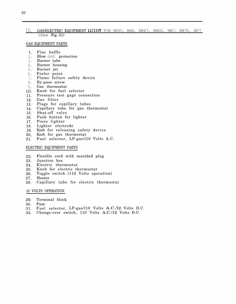
13. GAS/ELECTRIC EQUIPMENT FOR RM36C, RM46, RM47, RM66, RM67, RM76, RM77(See Fig. 51)
GAS EQUIPMENT PARTS
1. Flue baffle2. Blow out protection3. Burner tube4. Burner housing5. Burner jet6. Feeler point7. Flame failure safety device8. By-pass screw9. Gas thermostat
LO. Knob for fuel selector11. Pressure test gage connection12. Gas fi lter13. Plugs for capillary tubes14. Capillary tube for gas thermostat15. Shut-off valve16. Push button for lighter17. Piezo l ighter18. Lighter electrode19. Knob for releasing safety device20, Knob for gas thermostat21. Fuel selector, LP-gas/l10 Volts A.C.
ELECTRIC EQUIPMENT PARTS
22. Flexible cord with moulded plug23. Junction box24. Electric thermostat25. Knob for electric thermostat26. Toggle switch (110 Volts operation)27. Heater28. Capillary tube for electric thermostat
12 VOLTS OPERATION
29. Terminal block30. Fuse31. Fuel selector, LP-gas/l10 Volts A.C./l2 Volts D.C.32. Change-over switch, 110 Volts A.C./12 Volts D.C.

31
Fig. 51

32
THE GAS THERMOSTAT V- 35
The gas thermostat V-35 consists of three main parts:
Be 1 lows sys MechanismValve housing, see fig. 52 and fig.
BY-PASS SCREW
“ C O L D ” SCREW
TYPE V35
Gas inlet , Bellows system
Gas outletMcchbnism housing
Fig. 52 Fig. 53
Cleaning valve or valve seat in the V-35 t h e r m o s t a t
Dirt on the thermostat gas valve or seat prevents the thermostat valve from plete ly c los ing , consequently it lets through some gas when in closed position.This condition may prevent reducing the flame to the required minimum. It will causetoo low cabinet temperature. This can be controlled by turning the thermostat dialto If the flame does not go down to the flame (by-pass flame) it will benecessary to clean the thermostat valve and valve seat. Note: The thermostat willnot close to on setting at l east (40 F) .
unless the thermostat bulb is cooled down to
Proceed as follows:
a) Remove the p lug , spring and valve and clean the valve and the valve seat.
Also check that the size of by-pass screw is in accordance with table below.
Note: The adjusting screw on the thermostat is preset at the factory and should never be readjusted,
LOST THERMOSTAT CHARGE
If the thermostat control assembly loses its charge, it will become inactive. Totest for a lost charge, while the flame is reduced to minimum and the temperaturecontrol is set at a numbered position on its dial: Remove thermostat capillary tubefrom its clamp in the evaporator and warm end with the hand, If the flamefails to increase in sire, the thermostat has t its charge and the themostatmust be replaced.

33
THERMOSTAT REPLACEMENT
To replace the thermos tat, remove capillary from its clamp on the fresh foodevaporator fins, Remove the two sealing plugs, one on the outside and one on theinside of the cabinet. Straighten the capillary and pull it through the cabinet,Remove the thermostat by mscrewing it from the gas filter and the flame failuresafety device.
NOTE : Always, shut off the gas supply before removing any gas part from there fr igerator ,
By-pass screw sizes and part No.
1
14
RM46
s17
s17
By-passscrew
Part No.
34 19
17 28
17 28
17 28
17 28
couple into flame)
THE GAS BURNER (see fig.
The burner has the jet horizontallylocated and the burner mixing tube isformed as a bend with vertical outlet.
The air inlets are pre-set andtherefore not adjustable. The burnerand the burner holder are made in onepiece.
The burner is provided with the electric failure safety device and thethermocouple tip is pre-set.
Fig. 54
Fig. 55
To check for a correct flame, set thermostat to Flame should have a brightblue crown at the base of the
Burner jet sizes and input
Mode Butane Part Propane
RM24 24 289 00 24
34 200 26 43
43 200 26 51
51 200 26 52
5 1 200 26 53
Part Input BTU/h
600
26 1000
200 26 1100
200 36 1200
200 1360

34
TEE FLUE SYSTEM
The flue system consists of the following parts:
1) Central tube (built-in part of the boiler system and cannot be removed)2 ) F l u e3) Flue baffle with support wire
The purpose of the flue system is to provide a draft whichflame in to the central tube and supply sufficient primarythe flame.
pull the burnerand secondary air to
The flue baffle which is inserted in the central tube distributes the heat producedby the burner to the boiler system.
It is important that the correct size of baffle is used and that it is correctlylocated in the central tube in order to obtain the best cooling performance. Thesize and the distance between the lower end of the baffle and the lower end of thecentral tube for different refrigerator models are shown in table,
Baffle sites, height, and part No.
Baffle Width x Lengthinches
10 x 100 x 4
20 x 100 x 4
20 x 100 x 4
20 x 100 x 4
20 x 150 x 6
75 3
75 3
75 3
75 3
75 3
Part Baff le support wire
06 x:
289
289 00
289 00
17 21x) Baffle only Fig. 51
Flue obstructions
On gas refrigerators, the flue will require cleaning occasionally. To do this itwill be necessary to gain access to the back of the cabinet. When cleaning the f l u eproceed as follows:
Unscrew the outer burner shield and the burner housing, release the flue and liftout the baffle on its support wire from the top of the boiler tube.
From the top, clean the flue vith a suitable flue brush. Also clean the baffle,before putting back in place.
An obstruction in the flue will reduce or stop flue draft. Flue obstructions willcause odors outside refrigerator, slow freezing and higher cabinet temperatures.Flue stoppages may also cause the flame to burn outside the central tube,

17. THERMOELECTRIC FAILURE SAFETY DEVICE (see fig, 58)
All
Al l
models equipped with an automatic failure device.
S
Fig. 58
gas operated or combined gas/electric refrigerator models dealt with in thisservice instruction are equipped with an automatic failure device.
purpose of incorporating an automatic flame failure device in the burner assem-bly is to prevent unburned gas to escape from the burner and to avoid a fire hazard,if, for some reason or other, the flame has been extinguished or blown out,
The safety device consists of the following parts:
1.2.3.
6.7.8.9.
Spring loaded push buttonGas valveHousingSensing clement with the hot junction of thethermocoup (Feeler)Enamel insulated copper threadElectromagnetOuter tubeArmatureSpring
The safety device functions as follows:
By pressing the push button (1) the gas valve (2) is opened and the gas can pass housing (3) on to the At the burner the feeler (4) is located. When the gasflame of the burner is lit, some heat is transferred to the feeler The hotjunction of the thermocouple is thus heated and an electric current is generated .This current passes through the copper wire (5) to the electromagnet (6) and backthrough the outer tube (7). As soon as the electric current is generated, theelectromagnet attracts the armature (8) with the valve The push button can be released,
As long as current is flowing, the kept open and allows gas to pass co burner.
When the flame is extinguished, the heat transfer to the hot junction is and no electric current is generated. armature (8) with the valve (2) is forced back by the spring (9) and the gas flow through the valve (2) is c losed .
Important: lighting the burner the push button (1) should be pressed f held in that position about 10 seconds, otherwise the gas may not get the burner properly,

36
REPLACEMENT OF ELEMENT OF THE THERMOELECTRICFLAME FAILURE SAFETY
Fig. 59
replace the thermo-element of the thermoelectric flame failure safety ( see f ig . 59 ) .
1. plug A f the valve housing B .
2. Loosen the position nut C and lock nut D .
Screw off nut C, remove spacer and nut D. Release the thcrmo-element E fromburner housing F.
4. Bend carefully the new thermo-element to the same shape as the old one. Screwnut D into the new element,
Put the feeler through the hole in the burner housing F, refit the spacer andscrew the position nut C tight against the shoulder on the feeler, raking surethe nut D is free during this operation,
6. Tighten the lock nut D against the burner housing with a small wrench, ifnecessary holding nut C vith another wrench, Make sure the feeler is locatedas in f igure .
Check that no burrs are inside valve housing B which cause leaks,Screw plug A onto the valve housing B , taking care not to damage the threadedhole in the cap of the housing, Plug A must be properly tightened tothe valve housing to ensure contact betveen the thermo-element and the coil vithin the housing,
OF SAFETY VALVE
If the safety valve magnet is defective, it cannot be repaired but be replaced,
When the safety valve magnet needs replacement proceed as fol lows (see f ig,
2.
3.
4.
Unscrew the connection plug (A) on the thermocouple from the housing nut
Unscrew the housing nut (B) and remove the defective safety valve (C)from the housing
Fit a new magnet valve and ensurethat it is properly inserted inthe housing (D).
Fit the housing nut and theconnection plug (A) and check t h a ta good contact between the contactplug (E) on the thermocouple andthe contact (F) on the safetyvalve magnet is obtained.

REPLACEMENT OF HEATER
The electric heater is positioned in a pocket which is welded to the boiler tube,A wire clip holds the heater securely in the pocket (see fig. 61).
Wire clip
Fig. 61 Fig. 62 Fig. 63
RM46
To replace the heater, first check that the wall plug is disconnected, then unscrewlock screws A (Fig. 62) on the Lower lid B and upper lid C. Push the lid B downwardsand the upper lid C upwards (on and RM77 remove the plate D, Fig. 63).On the RM24 model it will also be necessary to remove the blow-out protection flue,
Remove the fibre glass insulation around the heater so that the heater is accessiblefor removal. Then bend aside the wire clip keeping the heater in proper position,disconnect the heater leads from the cord and iemove the heater.
Make sure the new heater is fully inserted before bending back the wire clip (withcaution, or it might snap off), Reset the electric connections. Be careful to putthe Pibre glass insulation back in its proper place and in such a way that the heaterleads will not be in direct contact with hot boiler tubes.
Model Prod. No. Voltage
RM24
RM36C
RM36C
RM46 ,RM47
RM46 ,RM47
RM66 ,RM67
RM66 ,RM67
RM76 ,RM77
926 39 02
926 45 03
926 45 04
926 46 03
926 46 04
926 47 03
926 47 04
926 48 03
12/110
110
12/110
110
12/110
110
12/110
110
It is essential that the remplacement heater be of the proper rating in order toprovide the correct heat input for the particular model.
The table below shows the correct heater for each model:
810.85
1.1
1.2
1.4
2.1
Watts Part No.
95
125
125
135
135
1 5 0
150
290
17 37
17 37
37
17 37
17 37
17 37
30 225

38
WIRING DIAGRAMS
for Thermostat Terminal12
B l a c k
110 Volts
Heating element
Terminalblock
Switch
Fig.
forRM36C, RM46, RM47RM66, RM67, RM76,RM77
HeaterThermostat
Fig. 6.5
l2V/llOV for RM36C, RM46, RM47, RM66, RM67
Terminal block
AC
‘LP Gos OFF
WIRINGDIAGRAM Heater
Switch
Fig.

20. PRESSURE DEVICES
The pressure at the burner should be checked at the time the refrigerator is startedup, After connecting the pressure gauge, set the thermostat dial at Turn onthe gas at the union cock and light burner. At the setting the pressurereading should be (280 mm). The L.P. gas is supplied directly to the thermostatfrom the regulator fitted on the gas bottle at pressure of 11” (280
Water U gauge (fig, 67)
The water gauge consists of a glass tube filled to with water. pressure is exerted on one side of the gauge, the water on side is forced downand there is a corresponding rise of water on the other side.
Water column pressure per square inch is indicated the difference of the twocolumns of water measured in inches.
A convenient scale reading in inches and tenths of an inch is bctveen thetwo columns.
When reading the gauge proceed as follows
If the gauge is filled with water to zero and the lower column is 5.5 inches(140 below zero, the other column will also be 5.5 inches (140 By addingthe tvo together 5.5 + 5.5 11 inches (280 mm) water column,
For accuracy of measurement a vater gauge is far superior to a low pressure gauge.If a low pressure gauge is used, it should be checked for accuracy against a water gauge occasionally .
WATER U I F - -.GAUGE
AdopterP a r t N o .
33 87
Fig.
LOW PRESSURE GAUGE
Low pressure gauge (Fischer) (fig, 64)
This gauge is calibrated to read in “inches of water column pressure”. It is astandard manometer reading and is colored red.
How to use the pressure gauge
When testing the pressure at the burner, remove the plug indicated with an arrow infig. 67 and fit the hose from the pressure gauge. Use adapter, part 33 87 It is very important that the gas operated refrigerators operate at correct pressurei . e . at the pressure stipulated for the refrigerator.
21. OPERATING
Experience over many years shows that incorrect installation and adjustments aremajor causes for unsatisfactory refrigeration.
40
Unsatisfactory refrigeration also results from improper operation by the user dueto misunderstanding or carelessness. Each refrigerator contains a pamphlet called“INSTRUCTIONS FOR USE” which should be followed to assure the best refrigerationresults. The servicer, as well as the user, should become thoroughly acquainted withthe contents.
A study of the following instructions will help the servicer to better instruct theuser, and will also help him to answer questions which may be asked.
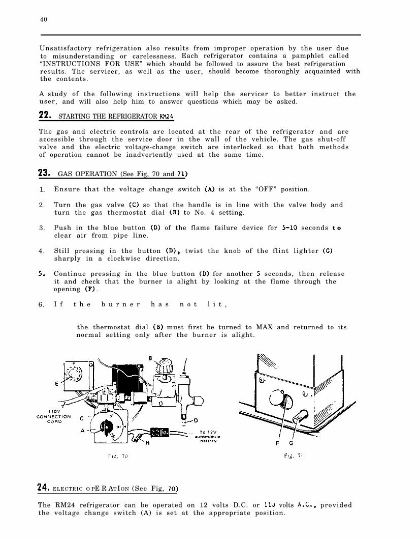
STARTING THE REFRIGERATOR
The gas and electric controls are located at the rear of the refrigerator and areaccessible through the service door in the wall of the vehicle. The gas shut-offvalve and the electric voltage-change switch are interlocked so that both methodsof operation cannot be inadvertently used at the same time.
GAS OPERATION (See Fig, 70 and
1. Ensure that the voltage change switch is at the “OFF” position.
2. Turn the gas valve so that the handle is in line with the valve body andturn the gas thermostat dial to No. 4 setting.
3. Push in the blue button of the flame failure device for seconds t oclear air from pipe line.
4. Still pressing in the button twist the knob of the fl int l ighter sharply in a clockwise direction.
Continue pressing in the blue button for another seconds, then releaseit and check that the burner is alight by looking at the flame through theopening .
6. I f t h e b u r n e r h a s n o t l i t ,
the thermostat dial must first be turned to MAX and returned to itsnormal setting only after the burner is alight.
ELECTRIC O PE R AT ION (See Fig,
The RM24 refrigerator can be operated on 12 volts D.C. or volts providedthe voltage change switch (A) is set at the appropriate position.

1. Turn off the gas valve (C), its handle then be pointing avay from the backof the cabinet.
Turn the voltage change switch (A) to the required setting, then connect there fr igerator to appropriate voltage supply,
When the electrical supply cord is connected to a 110 volt A.C. supply, tnevoltage on the switch (A) should show when connected to thevoltage on the switch (A) should show
3. Turn the electric thermostat knob (E) to No. 4.
HOW TO START THE REFRIGERATOR 25. RM47 RM67,
26. GAS OPERATION (Fig. 72)
1. To start the refrigerator turn the knob A to position gas valve isnow opened and the electric circuits are disconnected.
2. Turn the gas thermostat knob C to setting 4.
3. Pull the knob D of the flame failure safety device and after 5-10 seconds pressthe button E to the piezo lighter. The pressing may have to be repeated. Throughthe reflector F it can be observed that the burner is lit.
4. After the burner has been lit keep the knob in pulled out position for another5 seconds. Then release the knob and check through the reflector that t h eburner stays lit,
Note: After a replacement of the gas container or shut-off period thegas pipes are likely to be filled with air, In such a case the lightingprocedure has to be repeated until the air is pushed out of the pipes andthe gas has reached the burner.
27. ELECTRIC OPERATION (Fig, 72)
1. Check that the attachment plug of the flexible cord isthe main supply. The 12 volt connection is made at therear of the refrigerator.
2. Turn the knob A to “off” position, then press the knobdesired electric position.
correctly connected comarked terminals at the
in to bottom and turn to
3. Turn the thermostat knob G to setting 4.
When the refrigerator is equipped for 110 volts and 12 volt operation theturning movement of the knob A should be made as follows:In gas OFF position the knob is pressed and turned clockwise to the12 volt position, If 110 volt operation is desired press once more andcontinue the clockwise turning to the 110 volt position marked
LEVELING
In the boiler of the cooling unit, ammonia vapor is distilled from an ammonia-watermixture and carried to the finned condenser where it liquefies. The liquid f tothe evaporator inside the cabinet where it creates cold by evaporating into acirculating flow of hydrogen gas. If the evaporator is not level the liquid readilyaccumulates forming pockets can impair the gas circulation or block it com-plete ly , in which case, of course, cooling will
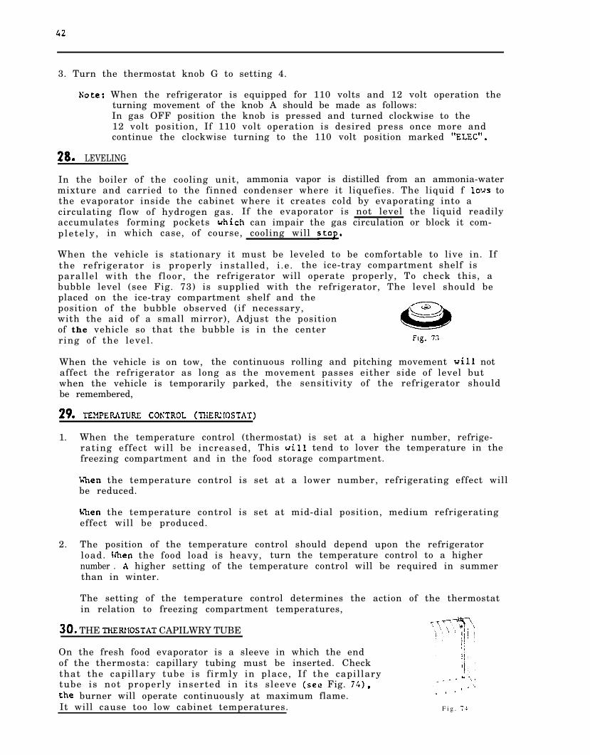
When the vehicle is stationary it must be leveled to be comfortable to live in. Ifthe refrigerator is properly installed, i .e. the ice-tray compartment shelf isparallel with the floor, the refrigerator will operate properly, To check this, abubble level (see Fig. 73) is supplied with the refrigerator, The level should beplaced on the ice-tray compartment shelf and theposition of the bubble observed (if necessary,with the aid of a small mirror), Adjust the positionof the vehicle so that the bubble is in the centerring of the level.
When the vehicle is on tow, the continuous rolling and pitching movement notaffect the refrigerator as long as the movement passes either side of level butwhen the vehicle is temporarily parked, the sensitivity of the refrigerator shouldbe remembered,
1. When the temperature control (thermostat) is set at a higher number, refrige-rating effect will be increased, This tend to lover the temperature in thefreezing compartment and in the food storage compartment.
the temperature control is set at a lower number, refrigerating effect willbe reduced.
the temperature control is set at mid-dial position, medium refrigeratingeffect will be produced.
2. The position of the temperature control should depend upon the refrigeratorload. the food load is heavy, turn the temperature control to a highernumber . higher setting of the temperature control will be required in summerthan in winter.
The setting of the temperature control determines the action of the thermostatin relation to freezing compartment temperatures,
THE CAPILWRY TUBE
On the fresh food evaporator is a sleeve in which the endof the thermosta: capillary tubing must be inserted. Checkthat the capillary tube is f irmly in place, If the capillarytube is not properly inserted in its sleeve Fig.
burner will operate continuously at maximum flame.
It will cause too low cabinet temperatures. F i g .

43
STORING FOOD IN THE
1.
2.
3.
4.
5.
Proper refrigeration requires free air circulation within the food storage partment. Restricted air circulation within the food storage compartment willcause higher cabinet temperatures, Rearrange foods.
It is also essential that the shelves are not covered with paper or largestorage containers.
Odorous foods or highly flavored foods should always be stored in covereddishes, plastic bags or wrapped in foil or wax paper, to prevent food odors.Vegetables, lettuce, etc. , should be covered to retain their crispness, put hot food into the refrigerator.
To reduce frost formation in and on the freezing compartment, cover storedliquids and moist foods and do not leave the door open longer than necessary,
When the refrigerator is heavily loaded, it takes longer for refrigerator peratures to lower, also increasing the ice making time. A very heavy load mayalso cause defrosting.
The cabinet interior should be cleaned regularly. Remove the shelves and wash thelining with lukewarm water to which a little baking soda may be added. Drythoroughly, especially around door frames and door gasket, water only shouldbe used to wash the cooling evaporator, and shelves.
Plastic dishes may be washed in warm soapy water not hotter than is bearable tothe hand. Do not expose them to dry heat, (Never use strong chemicals or abrasivecleaning materials on any part of the cabinet).
ICE
1. Do not use warm water, as it takes longer to freeze.
2. Faster freezing will result if water is used.
TRAVEL
The travel latch may be fitted to hold the door closed while in transit.
TO SHUT OFF THE CABINET
If for any reason refrigeration is not required over a period of weeks, the gastaps or electric switch should be turned off,
The cabinet and ice trays should be emptied, and dried and the door lefta jar ,
DOOR SEAL
1. It is essential, for correct operation, that the door gasket makes a good sealall around, against the front of the cabinet.
The compression of the gasket down the hinge side must not be too great: Thegasket should just contact the front of the cabinet when the door is closed.This is normally allowed for during manufacturing,

44
2.
3.
Failure of the door gasket to contact the front of the cabinet can be determinedvisually when the door is closed. Run a piece of thin cardboard along tne doorseal , inserted between the seal and the cabinet front, Nowhere should the card-board feel loose.
Improper door sealing on cabinets can be corrected by slackening the upper andlower hinge fixing screws and moving the door inwards or outwards as requireduntil a satisfactory seal is obtained.
If a good seal cannot be obtained, a new gasket should be installed.
It is also essential to check that the cabinet opening through which the freez-ing compartment enters the cabinet should be properly sealed by sealingcompound, If this seal leaks, warm air enters the cabinet causing high cabinettemperatures and frost formation on the freezing compartment.
ODORS INSIDE THE REFRIGERATOR
Odors inside the refrigerator are caused by improper food storage.
They may also be caused by too infrequent cleaning of the food compartment or therefrigerator has been shut off for some time with the door closed.
ODORS FROM FUMES
1. Odors outside the refrigerator may be caused by gas leaks. sure that allgas appliances are closed, Test gas connections and all joints in the gas linewith soap and water solution, up to and including gas cock. Never look for aleak with an open flame. Use a flashlight when necessary in looking for soapbubbles caused by leaks. The gas line should be free of kinks and sharp ends.
Turn on gas cock, light burner and test connections between the gas cock andthe burner carefully with soap and water.
2. Odors outside the refrigerator may be caused by improper burner flame.
The flame touches side of the boiler due to dislocation of the burner. Relocate.Burner dislocation may also cause smoke and of walls and ceiling.
4. Burner damaged. Replace.
The flame touches flue baffle. Correct position of baffle.
The flue tube is dirty, Clean the flue,
FLAME BLOWS OUT
If trouble is encountered with the flame blowing out under specially windy con-d i t ions , try to place the vehicle so that the wind does not blow directly into thevent outlets. If the trouble persists, set the thermostat on This lattermeasure can of course only be temporary such as when the vehicle is on tow, forafter several hours at this setting the foodstuffs in the cabinet may become toocold,
THE FLINT LIGHTER
If after some time of use the sparks from the lighter weaken, the flint willprobably have to be replaced.

45
Fig.
Fig. 76
To replace f l int, follov these steps:
1. Remove the
2. Remove the
3. Remove cap
outer burner shield by means of loosening the screws A (Fig. 75).
lighter by loosening the screw B retaining the lighter (Fig,
C and the spring D and tap out any remaining piece of flint__ and fit a nev
Be sure not to lose the small helical spring vhich presses the flint againstthe serrated wheel.
Replacement of the serrated vheel RM24
If after several years of use the lighter does not function properly even anew flint, the serrated vheel might be worn out and needs to be replaced.
1. Release the lighter as described above.
2. Unscrew the rod from the serrated wheel and fit a new wheel.
CAUTION The rod has to be unscrewed anti-clockwise.
PIEZO LIGHTER (Fig. 77)Fig. 77
The RM46, RM47, RM67, and RM77 models are equipped with a Pierocrystal lighting device vhich creates a spark over the burner when the button E ispushed in fully (see f ig. 72).

46
The Piezo lighter does not normally need any maintenance.
If by any reason the electrode or the lighter must be replaced, proceed as follows:
Replacement of electrode only.
1. Unscrew burner outer shield.
2. fastening screw “A” (Fig. 78) holding the electrode against side ofburner housing.
3. Loosen the electrode from its cable by unscrewing the electrode anti-clockwise.
4. Pit a new electrode,
CAUTION When fastening the electrode on the burner housing make sure that theinsulation plate is properly fitted between the burner housing andthe electrode (see f ig. 78).
Replacement of Piezo lighter complete
1. Release the Piezo lighter knob (see fig. 72)pulling the knob outwards.
2. Loosen outer burner shield and burner housing.
3. Loosen the fastening screw “A” (Fig. holdingburner housing.
4. Loosen the two screws on holder Now thepulled out at the rear of the cabinet.
5. To fit new lighter, reverse above procedure.
inside the cabinet by means of
the electrode against side of
lighter complete can be
Electrode
Fig.

TROUBLE SHOOTING ELECTRIC OPERATED REFRIGERATORS
Cause Remedy
The refrigerator not cool satisfactorily
Thennoatat at wrong setting.
Air circulation over cooling unitrestr i c ted .
Turn the thermostat dial to a higher number,
Remove any restriction,
Refrigerator not level. The refrigerator must be level in both direc-tions to operate properly. If in a trailer,always make sure it is level when parked,See par. 28.
Air leakage into cabinet. Check fit of door gasket, and that the seal-ing plug is in the hole for the thermostatcapillary in the rear wall of cabinet.See par, 36.
Evaporator heavily coated withf r o s t .
Defrost at more frequent intervals,
Heater faulty, wrong voltage or Use a new heater of appropriate voltage(see table page
Intermittent electricity supply. Look for loose connections or other reasonfor interruption and correct,
Drop in supply voltage. The supply voltage should be maintained atthe full rate,
Thermostat at too low setting.
Break in electrical circuit,
Turn thermostat dial to higher number.
Check fuses, switches, wiring, etc., andrepair the fault,
Heater faulty (open circuit) .
Thermostat faulty.
Failed cooling unit.
The refrigerator is too cold
Thermostat at wrong setting.
End of thermostat capillary tubeincorrectly located.
Replace with a new heater (see table page
Fit a new thermostat.
See par, 44.
Turn the thermostat dial to a lower number,
Re-insert the capillary end of thermostatfully in the sleeve under the ice-traycompartment. See par, 30.
Thermostat faulty. Have new thermostat fitted.
Heater wrongly connected toterminal block.
See wiring diagrams par. 19.

48
TROUBLE SHOOTING GAS OPERATED REFRIGERATORS
Cause
The refrigerator does not cool satisfactorily
Air circulation over cooling unitrestr i c ted .
Refr igerator not level.
Gas in bottle used up.
Feeler point of the flame failuredevice not heated enough byflame.
Clogged by-pass screw.
Burner jet or burner headclogged.
Flue baffle not inserted intocentral tube of the cooling unit.
Baffle too low in flue.
Wrong gas pressure at the burner.
Burner assembly may be adrift.
Thermostat at wrong setting.
Failed cooling unit.
The refrigerator is too cold
Thermostat at wrong setting.
End of thermoatat capillary tubeincorrectly located,
Incorrect size of by-pass screw.
Dirt in valve of the thermostat.
Remedy
Remove any restriction,
See par. 28.
Fit new bottle.
Adjust position of feeler point in flameSee par, 15,
Clean by-pass screw with alcohol and byblowing through with air. If necessary,replace by-pass screw.
Clean burner jet with alcohol and byblowing through with air, If necessary,replace burner jet, Clean the head with abrush.
Position of baffle (see table on page 34).
Position of baffle (see table on page 34).
Have pressure checked. Pressure must notfall below 11” (280 mm) water columnswhen thermostat is set on max.
Refit burner.
Turn the thermostat dial to a higher number,If necessary, replace thermostat.
See par, 44,
Turn the thermostat dial to a lower number.
Re-insert end of capillary tube in the clampon the fresh food compartment. See par. 30.
Replace by-pass screw to correct s i z e(see table page 33).
Clean the valve and valve seat in thethermostat (see par. 14).

49
44 FAILED REFRIGERATING UNIT
There are many things to consider before determining that the unit is faulty.
1. Leveling of the refrigerator
2. Ventilation
3. Cleaning and proper size of burner orifice
4. Cleaning and proper size of by-pass screw
5. Cleaning of thermos tat valve
6.
7.
8.
9.
10.
11.
12.
13.
14.
15.
Proper gas pressure
Correct flame
Correct position of baffle in boiler tube
No burnt-out heating element
Heating element in correct position
Correct size and vattage of heating element
Supply voltage corresponds to voltage stamped on heating element
No fluctuation in voltage supply
No loose electric connections
Thermostat intact
16. No unit leaks
17. Safety valve intact
45. PACKING OF DEFECTIVE UNITS
Particular attention must be paid to the packing of a replaced defective unit to en-sure during its return to the distributor that it will not be damaged in transit.
When the replacement unit is supplied cased, careful note should be taken of themanner in which it is packed, to ensure that the form of packing adopted, i.e. theuse of wood bracing and cardboard pads, is used when the defective unit is packedinto the case.
Structural distortion, particularly with the smaller units not having an angle ironf rame, can easily occur if the case containing the unit is roughly handled and ifinternal braces are not in position.

50
46. OPERATION ANALYSIS FOR REFRIGERATORS OPERATING ON ELECTRICITY
S Y M P T O M C A U S E
p Note: It will be noted in this tabulation
that several causes can be responsible for
the one effect. The real cause or causes
8 should bc determined by a process of See paragraph No. nation, investigating each possible cause,
starting at the top of the tabulation and
proceeding to the bottan.
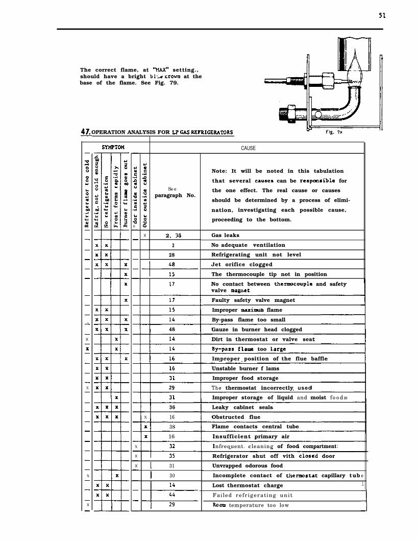
The correct flame, at setting.,should have a bright at thebase of the flame. See Fig. 79.
OPERATION ANALYSIS FOR
CAUSE
X
X
X
X
0
X
X
X
Note: It will be noted in this tabulation
that several can be for
the one effect. The real cause or causes
should be determined by a process of elimi-
nation, investigating each possible cause,
proceeding to the bottom.
Seeparagraph No.
Gas leaks
No adequate ventilation
X 2,
2
Refrigerating unit not level28
Jet orifice clogged
The thermocouple tip not in position
No contact between and safetyvalve
Faulty safety valve magnet
Improper flame
By-pass flame too small
48 Gauze in burner head clogged
Dirt in thermostat or valve seat
too
Improper position of the flue baffle
Unstable burner f lams
Improper food storage
The thermostat incorrectly used
Improper storage of liquid and moist foods
Leaky cabinet seals
Obstructed flue
36
X 16
38 Flame contacts central tube
16 Insufficient primary air
Infrequent cleaning of food compartment
Refrigerator shut off vith door
31 Unvrapped odorous food
Incomplete contact of capillary tub
Lost thermostat charge
30 e1
Failed refrigerating unit
temperature too low

52
48. PERIODIC MAINTENANCE
Once or twice a year depending on use, it is recommendedburner assembly, Proceed as follows:
1.
2.
3.
4.
5 .
6.
7.
8.
9 .
to clean and ad just the
Disconnect the gas pipe from the burner assembly,
Bemove the burner housing.
Remove the jet,
Clean the jet with alcohol and compressed air ONLY.
Clean the burner tube and especially the gauze with a brush. Blow withcompressed air,
At the same time, check the flue baffle: that it is clean and free from soot.Heavy soot formation indicates improper functioning of the burner. Clean baffleand flue. Further, clean cooling unit and floor under refrigerator.
Reassemble.
The entire gas installation should be checked for leaks at intervals. Test allpipe connections with soapy water, not with an open flame.
Check the burner with full flame (MAX) and with by-pass flame (0).Note: The thermostat will not close to by-pass on- setting “0” unless therefrigerator has been working for a few hours and the thermostat bulb is cooleddown to at least

����������� ������ �������������� ��� ���������������
�������������� �� �� ����� �� � �� ����������������������������� �������������
� ��� ������������� ��������� ���� ���������������� ������������� ��� �� ��� �� �������� ����� ���������� ��������� ������������������������ ����� ��� �������������������������� ������� ������ ��� ��� ����������� !"��� � ������������������ ��� � !����������������#$%�&����� '����� ���
(����������������������� �������&� �� ����� ����������'�
��������������


![INDEX [] · 2005-10-25 · 5 Bryant, John F, 27 Bryant, Levi Clinton, Sr, 109 Bryant, Lillie S, 101 Bryant, Linster, 101 Bryant, Litha L, 109 Bryant, Louisa M, 111 Bryant, Mary, 101](https://img.pdfslide.us/doc/110x75/5f4498e1f4a6be5e1a48d4d2/index-2005-10-25-5-bryant-john-f-27-bryant-levi-clinton-sr-109-bryant.jpg)