Embed Size (px)
Citation preview
1.
Service and Repair Manual
GTH-5519 (Deutz Tier 4i)From GTH5514B-101
to GTH5516B-4410
From GTH5516M-4411 to GTH5516M-5799
From GTH55M-5800
Serial Number Range
Part No. 1272852Rev A1September 2016
This manual includes:
Repair procedures
Fault Codes
Electrical and Hydraulic
Schematics
For detailed maintenance
procedures, Refer to the
appropriate Maintenance
Manual for your machine.
ii GTH-5519 Part No. 1272852
September 2016
ComplianceMachine Classifi cationGroup B/Type 3 as defined by ISO 16368
Machine Design LifeUnrestricted with proper operation, inspection and scheduled maintenance.
ImportantRead, understand and obey the safety rules and operating instructions in the Genie GTH-5519Operator's Manual before attempting any maintenance or repair procedure.
This manual provides troubleshooting and repair procedures for qualifi ed service professionals.
Basic mechanical, hydraulic and electrical skills are required to perform most procedures. However, several procedures require specialized skills, tools, lifting equipment and a suitable workshop. In these instances, we strongly recommend that maintenance and repair be performed at an authorized dealer service center.
Technical PublicationsGenie has endeavored to deliver the highest degree of accuracy possible. However, continuous improvement of our products is a Genie policy.Therefore, product specifications are subject to change without notice.
Readers are encouraged to notify Genie of errors and send in suggestions for improvement. All communications will be carefully considered for future printings of this and all other manuals.
Introduction
Copyright © 2016 by Terex Corporation
1272852 Rev A1 September 2016First Edition, First Printing
"Genie" and "GTH" are registered trademarks of Terex South Dakota, Inc. in the USA and many other countries.
Printed on recycled paper
Find a Manual for this ModelGo to http://www.genielift.com
Use the links to locate Operator's, Parts or Service Manuals.
Contact Us:http://www.genielift.come-mail: [email protected]
September 2016
Part No. 1272852 GTH-5519 iii
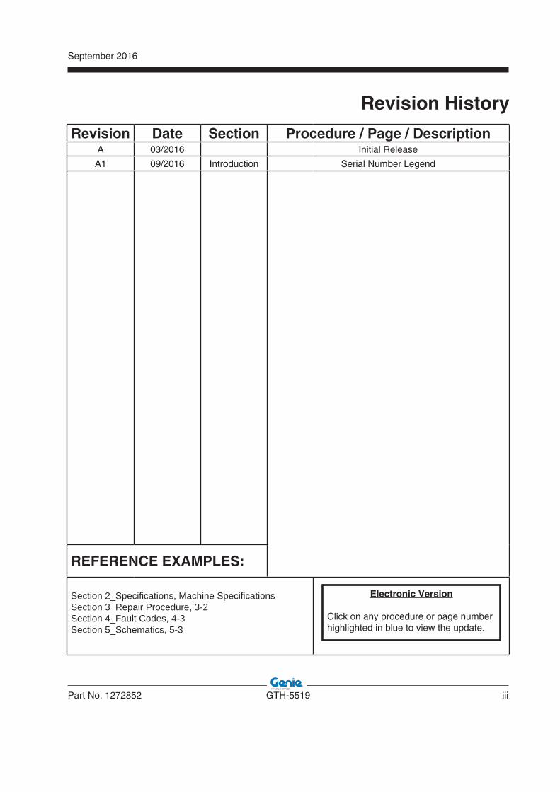
Revision Date Section Procedure / Page / DescriptionA 03/2016 Initial Release
A1 09/2016 Introduction Serial Number Legend
REFERENCE EXAMPLES:
Section 2_Specifi cations, Machine Specifi cationsSection 3_Repair Procedure, 3-2Section 4_Fault Codes, 4-3Section 5_Schematics, 5-3
Electronic Version
Click on any procedure or page number highlighted in blue to view the update.
Revision History
iv GTH-5519 Part No. 1272852
September 2016
REVISION HISTORY, CONTINUED
Revision Date Section Procedure / Page / Description
REFERENCE EXAMPLES:
Section 2_Specifi cations, Machine Specifi cationsSection 3_Repair Procedure, 3-2Section 4_Fault Codes, 4-3Section 5_Schematics, 5-3
Electronic Version
Click on any procedure or page number highlighted in blue to view the update.
September 2016
Part No. 1272852 GTH-5519 v
INTRODUCTION
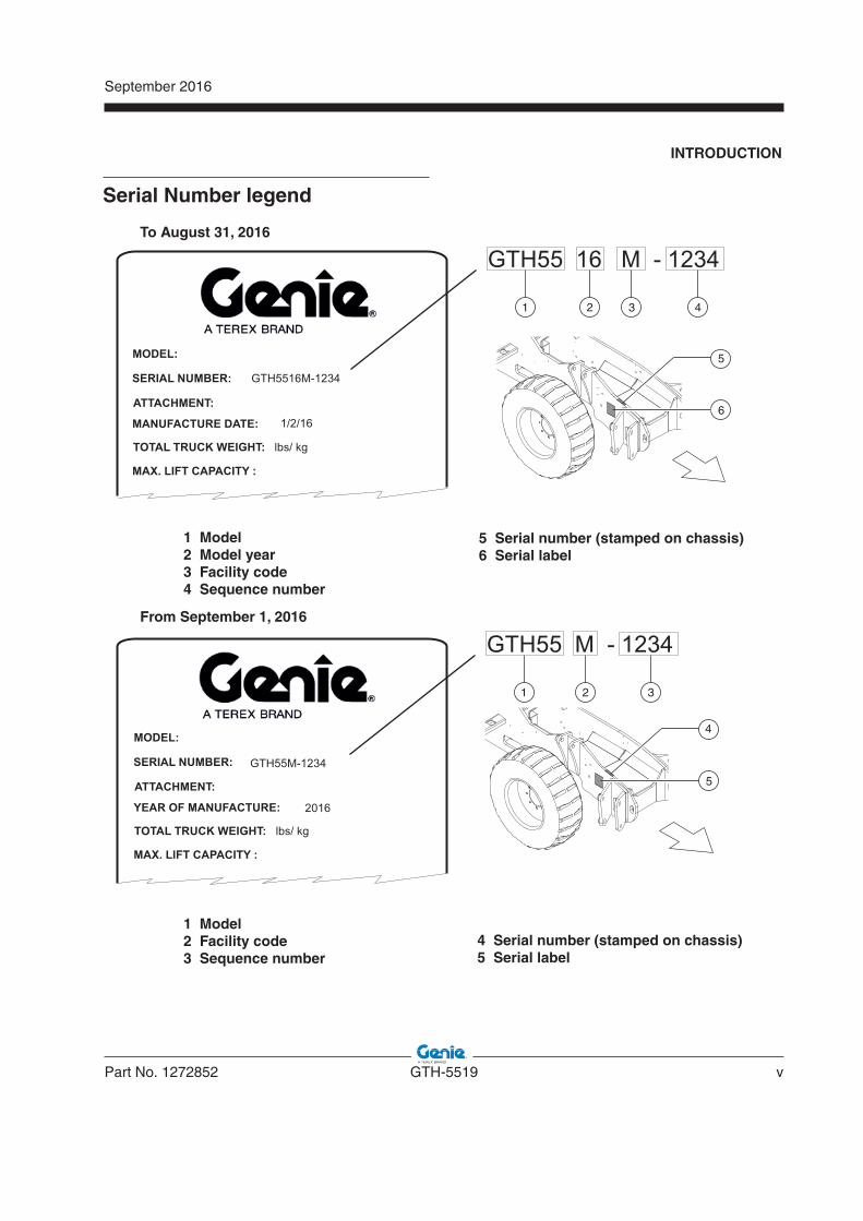
Serial Number legend
vi GTH-5519 Part No. 1272852
September 2016
This page intentionally left blank.
September 2016
Part No. 1272852 GTH-5519 vii
Section 1 • Safety Rules
Danger
Failure to obey the instructions and safety rulesin this manual and the appropriate Operator's Manual on your machine will result in death or serious injury.Many of the hazards identified in the Operator’s Manual are also safety hazards when maintenance and repair procedures are performed.
Do Not Perform MaintenanceUnless:
You are trained and qualified to perform maintenance on this machine.
You read, understand and obey: - manufacturer’s instructions and safety rules- employer’s safety rules and worksite
regulations - applicable governmental regulations
You have the appropriate tools, lifting equipment and a suitable workshop.
Safety Rules
viii GTH-5519 Part No. 1272852
September 2016Section 1 • Safety Rules
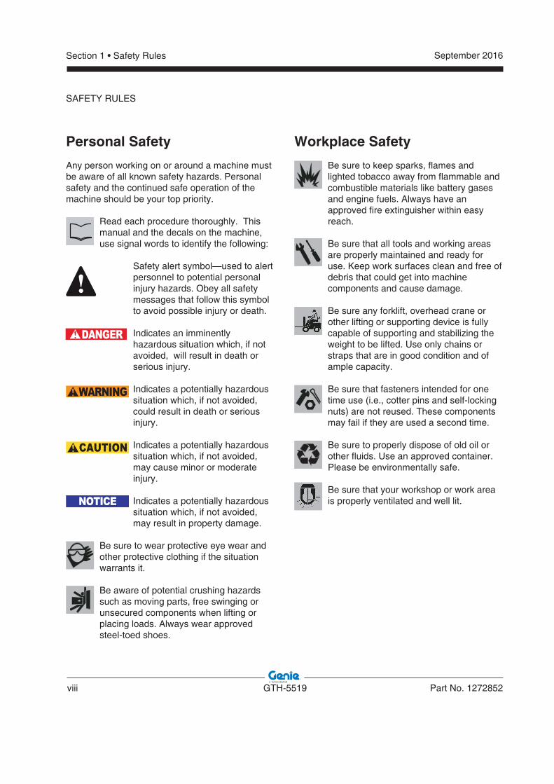
Personal Safety
Any person working on or around a machine must be aware of all known safety hazards. Personal safety and the continued safe operation of the machine should be your top priority.
Read each procedure thoroughly. This manual and the decals on the machine, use signal words to identify the following:
Safety alert symbol—used to alert personnel to potential personal injury hazards. Obey all safety messages that follow this symbol to avoid possible injury or death.
Indicates an imminently hazardous situation which, if not avoided, will result in death or serious injury.
Indicates a potentially hazardous situation which, if not avoided, could result in death or serious injury.
Indicates a potentially hazardous situation which, if not avoided, may cause minor or moderate injury.
Indicates a potentially hazardous situation which, if not avoided, may result in property damage.
Be sure to wear protective eye wear and other protective clothing if the situation warrants it.
Be aware of potential crushing hazards such as moving parts, free swinging or unsecured components when lifting or placing loads. Always wear approved steel-toed shoes.
DANGER
WARNING
CAUTION
NOTICE
Workplace Safety
Be sure to keep sparks, flames and lighted tobacco away from flammable and combustible materials like battery gases and engine fuels. Always have an approved fire extinguisher within easy reach.
Be sure that all tools and working areas are properly maintained and ready for use. Keep work surfaces clean and free of debris that could get into machine components and cause damage.
Be sure any forklift, overhead crane or other lifting or supporting device is fully capable of supporting and stabilizing the weight to be lifted. Use only chains or straps that are in good condition and of ample capacity.
Be sure that fasteners intended for one time use (i.e., cotter pins and self-locking nuts) are not reused. These components may fail if they are used a second time.
Be sure to properly dispose of old oil or other fluids. Use an approved container. Please be environmentally safe.
Be sure that your workshop or work area is properly ventilated and well lit.
SAFETY RULES
September 2016
Part No. 1272852 GTH-5519 ix
Introduction
Important Information .................................................................................. ii
Revision History...........................................................................................iii
Serial Number Legend................................................................................. v
Section 1 Safety Rules
General Safety Rules .................................................................................vii
Section 2 Specifi cations
Machine Specifications ...........................................................................2 - 1
Performance Specifications ....................................................................2 - 2
Hydraulic Specifications .........................................................................2 - 3
Hydraulic Components Specifications ....................................................2 - 4
Function Manifold Specifications ............................................................2 - 5
Air Conditioner Refrigerant Specifications ..............................................2 - 5
Deutz TD 2.9 L4 Engine .........................................................................2 - 6
Comer Axle .............................................................................................2 - 7
Hydraulic Hose and Fitting Torque Specifications ..................................2 - 8
Torque Procedure...................................................................................2 - 9
SAE and Metric Fasteners Torque Charts............................................2 - 10
Section 3 Repair Procedures
Introduction .............................................................................................3 - 1
Boom Components
1-1 Boom ............................................................................................3 - 2
1-2 Boom Lift Cylinder ........................................................................3 - 6
1-3 Boom Extend Cylinder..................................................................3 - 7
1-4 Fork Level Cylinder ......................................................................3 - 8
1-5 Fork Tilt Cylinder ..........................................................................3 - 9
Table of Contents
x GTH-5519 Part No. 1272852
September 2016
TABLE OF CONTENTS
Section 3 Repair Procedures, continued
Operator's compartment
2-1 Operator’s Compartment ............................................................3 - 12
2-2 Machine Controls .......................................................................3 - 14
Fuel and Hydraulic Tanks
3-1 Fuel Tank ...................................................................................3 - 18
3-2 Hydraulic Tank ...........................................................................3 - 19
Engines
4-1 Engines ......................................................................................3 - 20
4-2 Engine Fault Codes ....................................................................3 - 20
Axle
5-1 Axle ............................................................................................3 - 21
Hydraulic pumps
6-1 Boom and Steering Function Pump ...........................................3 - 22
6-2 Hydrostatic Transmission Pump.................................................3 - 26
Manifolds
7-1 Function Manifold .......................................................................3 - 30
7-2 Valve Coils .................................................................................3 - 34
Section 4 Fault Codes
Introduction .............................................................................................4 - 1
Diagnostic Display ..................................................................................4 - 2
Engine Fault Codes - Models with Deutz TD 2.9 L4...............................4 - 3
September 2016
Part No. 1272852 GTH-5519 xi
Section 5 Schematics
Introduction .............................................................................................5 - 1
Electrical and Hydraulic Symbol Legends ..............................................5 - 2
Electrical Schematic ...............................................................................5 - 3
Hydraulic Schematic .............................................................................5 - 27
TABLE OF CONTENTS
xii GTH-5519 Part No. 1272852
September 2016
TABLE OF CONTENTS
This page intentionally left blank.

September 2016
Part No. 1272852 GTH-5519 2-1
Section 2 • Specifications
Machine Specifi cations
Fluid capacitiesFuel tank 15.9 gallons
60 liters
Hydraulic tank 16.4 gallons62 liters
Hydraulic system(including tank)
25 gallons95 liters
For operational specifi cations, refer to the Operator's Manual.
Tires and wheels
Tire size 12 x 16.5
Tire ply rating 10
Weight, rough terrain tire wheel(air filled)
106 lbs48 kg
Weight, rough terrain tire wheel(foam filled)
320 lbs145 kg
Weight, rough terrain solid tire wheel
278 lbs126 kg
Tire pressure(models with air-filled tires)
65 psi4.5 bar
Lug nut torque 295 ft-lbs400 Nm
Lug pattern 8 x 10.827
Wheel diameter 32.3 in820 mm
Wheel width 12.3 in313 mm
Continuous improvement of our products is a Genie policy. Product specifi cations are subject to change without notice.
Specifi cations
2-2 GTH-5519 Part No. 1272852
September 2016Section 2 • Specifications
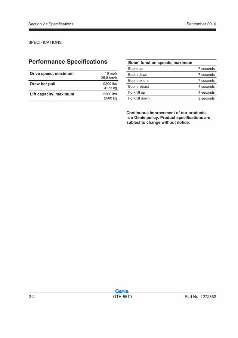
Performance Specifi cations
Drive speed, maximum 16 mph25,8 km/h
Draw bar pull 9200 lbs4173 kg
Lift capacity, maximum 5500 lbs2500 kg
Boom function speeds, maximumBoom up 7 seconds
Boom down 7 seconds
Boom extend 7 seconds
Boom retract 4 seconds
Fork tilt up 4 seconds
Fork tilt down 3 seconds
Continuous improvement of our products is a Genie policy. Product specifi cations are subject to change without notice.
SPECIFICATIONS
September 2016
Part No. 1272852 GTH-5519 2-3
Section 2 • Specifications
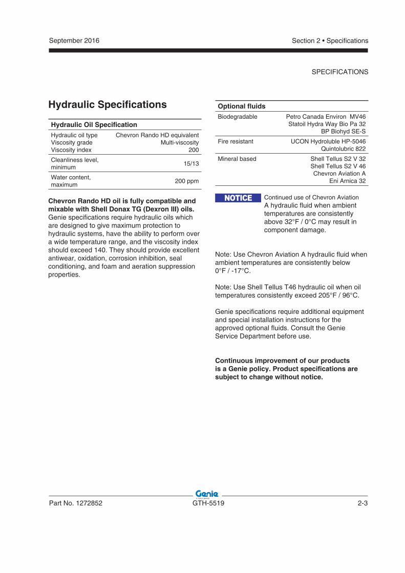
Hydraulic Specifi cations
Hydraulic Oil Specifi cation
Hydraulic oil typeViscosity gradeViscosity index
Chevron Rando HD equivalent Multi-viscosity
200
Cleanliness level, minimum
15/13
Water content, maximum
200 ppm
Chevron Rando HD oil is fully compatible and mixable with Shell Donax TG (Dexron III) oils.Genie specifications require hydraulic oils which are designed to give maximum protection to hydraulic systems, have the ability to perform over a wide temperature range, and the viscosity index should exceed 140. They should provide excellent antiwear, oxidation, corrosion inhibition, seal conditioning, and foam and aeration suppression properties.
Optional fl uids
Biodegradable Petro Canada Environ MV46Statoil Hydra Way Bio Pa 32
BP Biohyd SE-S
Fire resistant UCON Hydroluble HP-5046Quintolubric 822
Mineral based Shell Tellus S2 V 32Shell Tellus S2 V 46Chevron Aviation A
Eni Arnica 32
Continued use of Chevron Aviation A hydraulic fluid when ambient temperatures are consistently above 32°F / 0°C may result in component damage.
Note: Use Chevron Aviation A hydraulic fluid when ambient temperatures are consistently below 0°F / -17°C.
Note: Use Shell Tellus T46 hydraulic oil when oil temperatures consistently exceed 205°F / 96°C.
Genie specifications require additional equipment and special installation instructions for the approved optional fluids. Consult the Genie Service Department before use.
Continuous improvement of our products is a Genie policy. Product specifi cations are subject to change without notice.
NOTICE
SPECIFICATIONS
2-4 GTH-5519 Part No. 1272852
September 2016Section 2 • Specifications
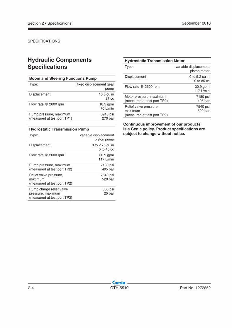
Hydraulic ComponentsSpecifi cations
Boom and Steering Functions PumpType: fixed displacement gear
pump
Displacement 16.5 cu in27 cc
Flow rate @ 2600 rpm 18.5 gpm70 L/min
Pump pressure, maximum(measured at test port TP1)
3915 psi270 bar
Hydrostatic Transmission PumpType: variable displacement
piston pump
Displacement 0 to 2.75 cu in0 to 45 cc
Flow rate @ 2600 rpm 30.9 gpm117 L/min
Pump pressure, maximum (measured at test port TP2)
7180 psi495 bar
Relief valve pressure, maximum(measured at test port TP2)
7540 psi520 bar
Pump charge relief valve pressure, maximum(measured at test port TP3)
360 psi25 bar
Hydrostatic Transmission MotorType: variable displacement
piston motor
Displacement 0 to 5.2 cu in0 to 85 cc
Flow rate @ 2600 rpm 30.9 gpm117 L/min
Motor pressure, maximum (measured at test port TP2)
7180 psi495 bar
Relief valve pressure, maximum(measured at test port TP2)
7540 psi520 bar
Continuous improvement of our products is a Genie policy. Product specifi cations are subject to change without notice.
SPECIFICATIONS
September 2016
Part No. 1272852 GTH-5519 2-5
Section 2 • Specifications
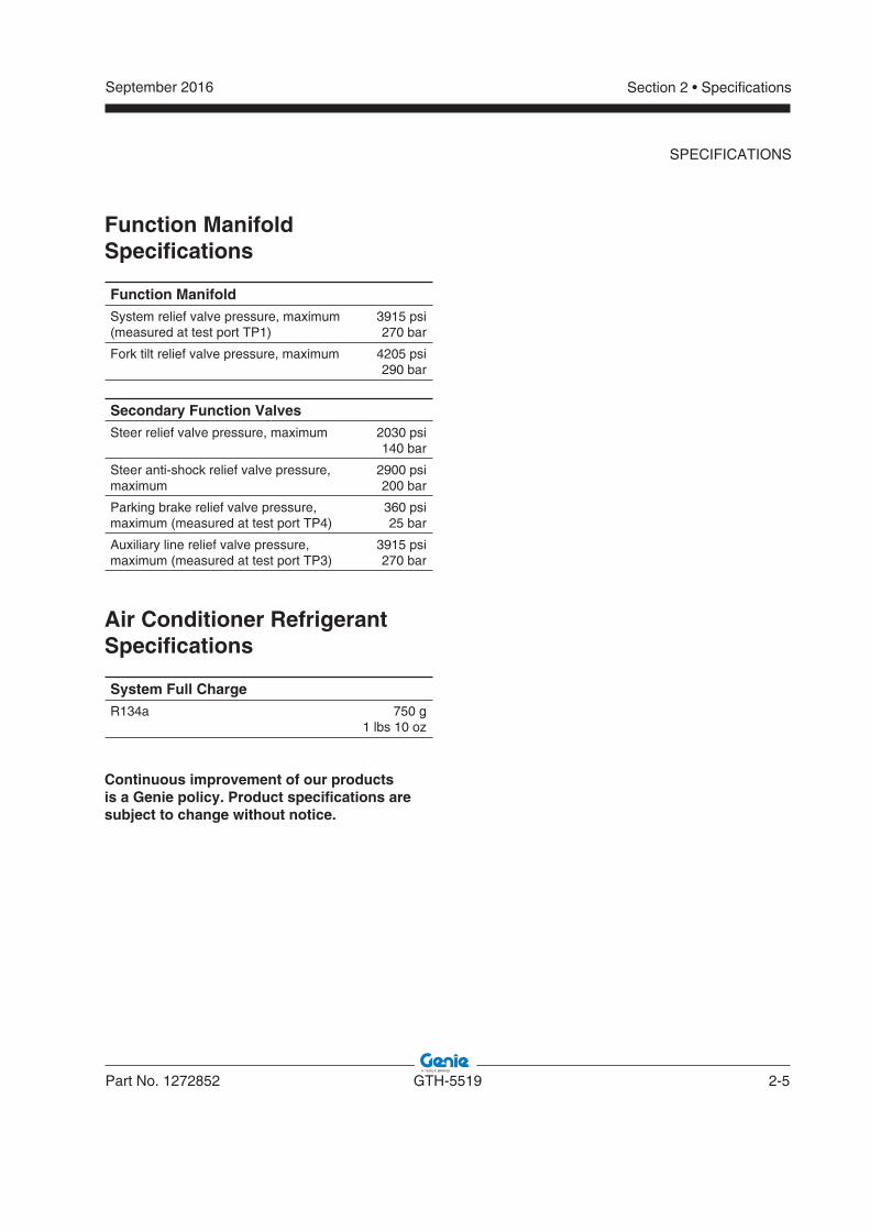
Function ManifoldSpecifi cations
Function ManifoldSystem relief valve pressure, maximum (measured at test port TP1)
3915 psi270 bar
Fork tilt relief valve pressure, maximum 4205 psi290 bar
Secondary Function ValvesSteer relief valve pressure, maximum 2030 psi
140 bar
Steer anti-shock relief valve pressure, maximum
2900 psi200 bar
Parking brake relief valve pressure, maximum (measured at test port TP4)
360 psi25 bar
Auxiliary line relief valve pressure, maximum (measured at test port TP3)
3915 psi270 bar
Air Conditioner RefrigerantSpecifi cations
System Full ChargeR134a 750 g
1 lbs 10 oz
Continuous improvement of our products is a Genie policy. Product specifi cations are subject to change without notice.
SPECIFICATIONS
2-6 GTH-5519 Part No. 1272852
September 2016Section 2 • Specifications
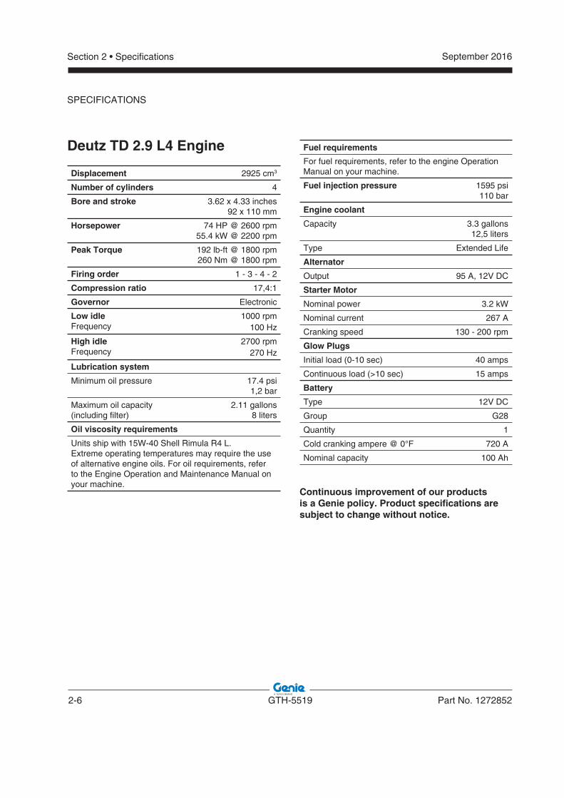
Deutz TD 2.9 L4 Engine
Displacement 2925 cm3
Number of cylinders 4
Bore and stroke 3.62 x 4.33 inches92 x 110 mm
Horsepower 74 HP @ 2600 rpm55.4 kW @ 2200 rpm
Peak Torque 192 lb-ft @ 1800 rpm260 Nm @ 1800 rpm
Firing order 1 - 3 - 4 - 2
Compression ratio 17,4:1
Governor Electronic
Low idleFrequency
1000 rpm100 Hz
High idleFrequency
2700 rpm270 Hz
Lubrication system
Minimum oil pressure 17.4 psi1,2 bar
Maximum oil capacity(including filter)
2.11 gallons8 liters
Oil viscosity requirements
Units ship with 15W-40 Shell Rimula R4 L.Extreme operating temperatures may require the use of alternative engine oils. For oil requirements, refer to the Engine Operation and Maintenance Manual on your machine.
Fuel requirements
For fuel requirements, refer to the engine Operation Manual on your machine.
Fuel injection pressure 1595 psi110 bar
Engine coolant
Capacity 3.3 gallons12,5 liters
Type Extended Life
Alternator
Output 95 A, 12V DC
Starter Motor
Nominal power 3.2 kW
Nominal current 267 A
Cranking speed 130 - 200 rpm
Glow Plugs
Initial load (0-10 sec) 40 amps
Continuous load (>10 sec) 15 amps
Battery
Type 12V DC
Group G28
Quantity 1
Cold cranking ampere @ 0°F 720 A
Nominal capacity 100 Ah
Continuous improvement of our products is a Genie policy. Product specifi cations are subject to change without notice.
SPECIFICATIONS
September 2016
Part No. 1272852 GTH-5519 2-7
Section 2 • Specifications
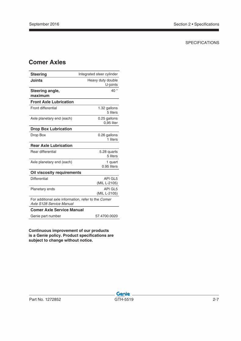
Comer Axles
Steering Integrated steer cylinder
Joints Heavy duty double U-joints
Steering angle, maximum
40 °
Front Axle LubricationFront differential 1.32 gallons
5 liters
Axle planetary end (each) 0.25 gallons0,95 liter
Drop Box LubricationDrop Box 0.26 gallons
1 liters
Rear Axle LubricationRear differential 5.28 quarts
5 liters
Axle planetary end (each) 1 quart0.95 liters
Oil viscosity requirementsDifferential API GL5
(MIL L-2105)
Planetary ends API GL5(MIL L-2105)
For additional axle information, refer to the Comer Axle S128 Service Manual
Comer Axle Service ManualGenie part number 57.4700.0020
Continuous improvement of our products is a Genie policy. Product specifi cations are subject to change without notice.
SPECIFICATIONS
2-8 GTH-5519 Part No. 1272852
September 2016Section 2 • Specifications
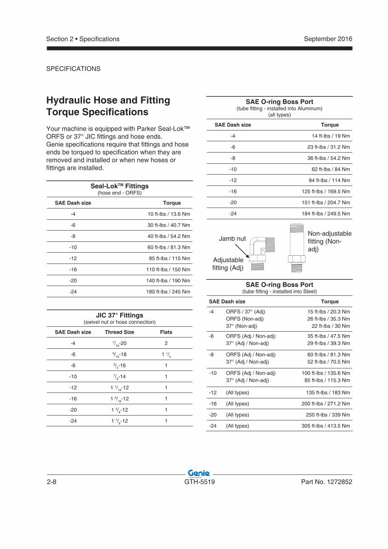
Hydraulic Hose and FittingTorque Specifi cations
Your machine is equipped with Parker Seal-Lok™ ORFS or 37° JIC fittings and hose ends.Genie specifications require that fittings and hose ends be torqued to specification when they are removed and installed or when new hoses or fittings are installed.
Seal-LokTM Fittings(hose end - ORFS)
SAE Dash size Torque
-4 10 ft-lbs / 13.6 Nm
-6 30 ft-lbs / 40.7 Nm
-8 40 ft-lbs / 54.2 Nm
-10 60 ft-lbs / 81.3 Nm
-12 85 ft-lbs / 115 Nm
-16 110 ft-lbs / 150 Nm
-20 140 ft-lbs / 190 Nm
-24 180 ft-lbs / 245 Nm
JIC 37° Fittings(swivel nut or hose connection)
SAE Dash size Thread Size Flats
-4 7/16-20 2
-6 9/16-18 1 1/4
-8 3/4-16 1
-10 7/8-14 1
-12 1 1/16-12 1
-16 1 5/16-12 1
-20 1 5/8-12 1
-24 1 7/8-12 1
SAE O-ring Boss Port(tube fitting - installed into Aluminum)
(all types)
SAE Dash size Torque
-4 14 ft-lbs / 19 Nm
-6 23 ft-lbs / 31.2 Nm
-8 36 ft-lbs / 54.2 Nm
-10 62 ft-lbs / 84 Nm
-12 84 ft-lbs / 114 Nm
-16 125 ft-lbs / 169.5 Nm
-20 151 ft-lbs / 204.7 Nm
-24 184 ft-lbs / 249.5 Nm
SAE O-ring Boss Port(tube fitting - installed into Steel)
SAE Dash size Torque
-4 ORFS / 37° (Adj)ORFS (Non-adj)37° (Non-adj)
15 ft-lbs / 20.3 Nm26 ft-lbs / 35.3 Nm
22 ft-lbs / 30 Nm
-6 ORFS (Adj / Non-adj)37° (Adj / Non-adj)
35 ft-lbs / 47.5 Nm29 ft-lbs / 39.3 Nm
-8 ORFS (Adj / Non-adj)37° (Adj / Non-adj)
60 ft-lbs / 81.3 Nm52 ft-lbs / 70.5 Nm
-10 ORFS (Adj / Non-adj)37° (Adj / Non-adj)
100 ft-lbs / 135.6 Nm85 ft-lbs / 115.3 Nm
-12 (All types) 135 ft-lbs / 183 Nm
-16 (All types) 200 ft-lbs / 271.2 Nm
-20 (All types) 250 ft-lbs / 339 Nm
-24 (All types) 305 ft-lbs / 413.5 Nm
SPECIFICATIONS
Non-adjustablefitting (Non-adj)
Jamb nut
Adjustablefitting (Adj)
September 2016
Part No. 1272852 GTH-5519 2-9
Section 2 • Specifications
SPECIFICATIONS
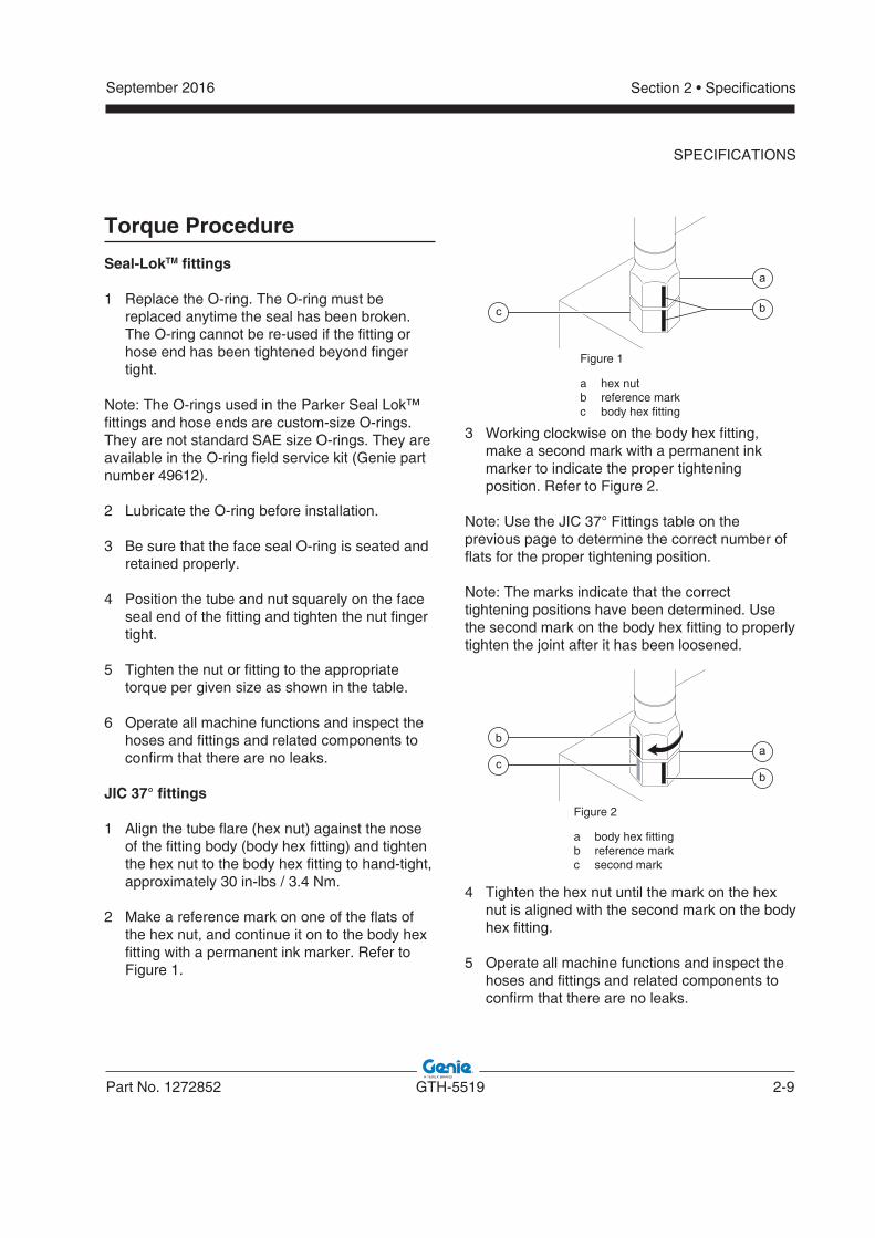
Torque Procedure
Seal-LokTM fi ttings
1 Replace the O-ring. The O-ring must be replaced anytime the seal has been broken.
The O-ring cannot be re-used if the fitting or hose end has been tightened beyond finger tight.
Note: The O-rings used in the Parker Seal Lok™ fittings and hose ends are custom-size O-rings.They are not standard SAE size O-rings. They are available in the O-ring field service kit (Genie part number 49612).
2 Lubricate the O-ring before installation.
3 Be sure that the face seal O-ring is seated and retained properly.
4 Position the tube and nut squarely on the face seal end of the fitting and tighten the nut finger tight.
5 Tighten the nut or fitting to the appropriate torque per given size as shown in the table.
6 Operate all machine functions and inspect the hoses and fittings and related components to confirm that there are no leaks.
JIC 37° fi ttings
1 Align the tube flare (hex nut) against the nose of the fitting body (body hex fitting) and tighten the hex nut to the body hex fitting to hand-tight, approximately 30 in-lbs / 3.4 Nm.
2 Make a reference mark on one of the flats of the hex nut, and continue it on to the body hex fitting with a permanent ink marker. Refer to Figure 1.
3 Working clockwise on the body hex fitting, make a second mark with a permanent ink marker to indicate the proper tightening position. Refer to Figure 2.
Note: Use the JIC 37° Fittings table on the previous page to determine the correct number of flats for the proper tightening position.
Note: The marks indicate that the correct tightening positions have been determined. Use the second mark on the body hex fitting to properly tighten the joint after it has been loosened.
4 Tighten the hex nut until the mark on the hex nut is aligned with the second mark on the body hex fitting.
5 Operate all machine functions and inspect the hoses and fittings and related components to confirm that there are no leaks.
a
bc
a
bc
b
Figure 1
a hex nutb reference markc body hex fitting
Figure 2
a body hex fittingb reference markc second mark
2-10 GTH-5519 Part No. 1272852
September 2016Section 2 • Specifications
SPECIFICATIONS
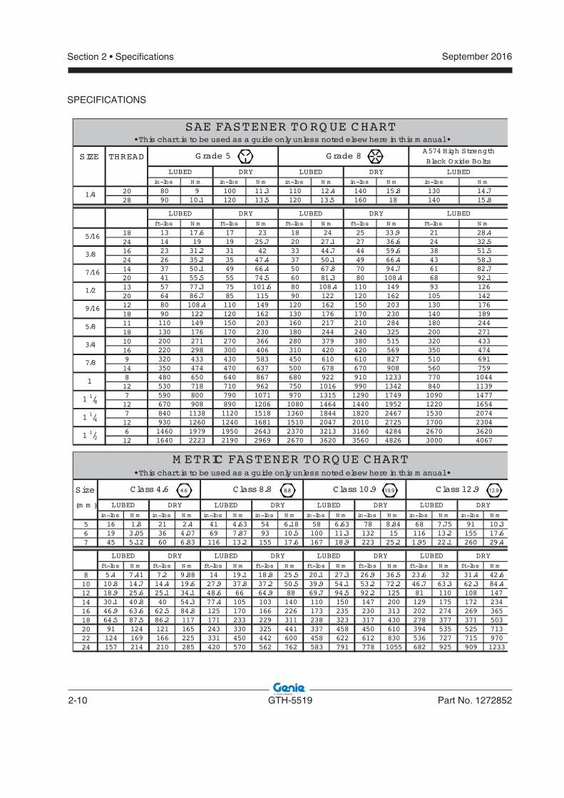
Size
(m m )in-lbs N m in-lbs N m in-lbs N m in-lbs N m in-lbs N m in-lbs N m in-lbs N m in-lbs N m
5 16 1.8 21 2.4 41 4.63 54 6.18 58 6.63 78 8.84 68 7.75 91 10.36 19 3.05 36 4.07 69 7.87 93 10.5 100 11.3 132 15 116 13.2 155 17.67 45 5.12 60 6.83 116 13.2 155 17.6 167 18.9 223 25.2 1.95 22.1 260 29.4
ft-lbs N m ft-lbs N m ft-lbs N m ft-lbs N m ft-lbs N m ft-lbs N m ft-lbs N m ft-lbs N m
8 5.4 7.41 7.2 9.88 14 19.1 18.8 25.5 20.1 27.3 26.9 36.5 23.6 32 31.4 42.610 10.8 14.7 14.4 19.6 27.9 37.8 37.2 50.5 39.9 54.1 53.2 72.2 46.7 63.3 62.3 84.412 18.9 25.6 25.1 34.1 48.6 66 64.9 88 69.7 94.5 92.2 125 81 110 108 14714 30.1 40.8 40 54.3 77.4 105 103 140 110 150 147 200 129 175 172 23416 46.9 63.6 62.5 84.8 125 170 166 226 173 235 230 313 202 274 269 36518 64.5 87.5 86.2 117 171 233 229 311 238 323 317 430 278 377 371 50320 91 124 121 165 243 330 325 441 337 458 450 610 394 535 525 71322 124 169 166 225 331 450 442 600 458 622 612 830 536 727 715 97024 157 214 210 285 420 570 562 762 583 791 778 1055 682 925 909 1233
LUBED DRY LUBED DRYLUBED DRY LUBED DRY
LUBEDDRYLUBED
Class 12.9Class 4.6
DRYLUBED
M ETRIC FASTENER TO RQ UE CHART• This chart is to be used as a guide only unless noted elsew here in this m anual •
LUBED DRY
Class 10.9Class 8.8
DRY
SIZE THREAD
in-lbs N m in-lbs N m in-lbs N m in-lbs N m in-lbs N m
20 80 9 100 11.3 110 12.4 140 15.8 130 14.728 90 10.1 120 13.5 120 13.5 160 18 140 15.8
ft-lbs N m ft-lbs N m ft-lbs N m ft-lbs N m ft-lbs N m
18 13 17.6 17 23 18 24 25 33.9 21 28.424 14 19 19 25.7 20 27.1 27 36.6 24 32.516 23 31.2 31 42 33 44.7 44 59.6 38 51.524 26 35.2 35 47.4 37 50.1 49 66.4 43 58.314 37 50.1 49 66.4 50 67.8 70 94.7 61 82.720 41 55.5 55 74.5 60 81.3 80 108.4 68 92.113 57 77.3 75 101.6 80 108.4 110 149 93 12620 64 86.7 85 115 90 122 120 162 105 14212 80 108.4 110 149 120 162 150 203 130 17618 90 122 120 162 130 176 170 230 140 18911 110 149 150 203 160 217 210 284 180 24418 130 176 170 230 180 244 240 325 200 27110 200 271 270 366 280 379 380 515 320 43316 220 298 300 406 310 420 420 569 350 4749 320 433 430 583 450 610 610 827 510 69114 350 474 470 637 500 678 670 908 560 7598 480 650 640 867 680 922 910 1233 770 104412 530 718 710 962 750 1016 990 1342 840 11397 590 800 790 1071 970 1315 1290 1749 1090 147712 670 908 890 1206 1080 1464 1440 1952 1220 16547 840 1138 1120 1518 1360 1844 1820 2467 1530 207412 930 1260 1240 1681 1510 2047 2010 2725 1700 23046 1460 1979 1950 2643 2370 3213 3160 4284 2670 362012 1640 2223 2190 2969 2670 3620 3560 4826 3000 4067
LUBEDDRYLUBED
SAE FASTENER TO RQ UE CHART
Grade 5
DRYLUBED
• This chart is to be used as a guide only unless noted elsew here in this m anual •
A574 High Strength
Black Oxide BoltsGrade 8
LUBED
1/4
LUBED DRY LUBED DRY
1 1/2
9/16
5/8
3/4
7/8
1
1 1/8
1 1/4
5/16
3/8
7/16
1/2
10.9 12.98.84.6
September 2016
Part No. 1272852 GTH-5519 3-1
Section 3 • Repair Procedures
Repair Procedures
Observe and Obey:
Repair procedures shall be completed by a person trained and qualified on the repair of this machine.
Immediately tag and remove from service a damaged or malfunctioning machine.
Repair any machine damage or malfunction before operating the machine.
Before Repairs Start:
Read, understand and obey the safety rules and operating instructions in the appropriate operator’s manual on your machine.
Be sure that all necessary tools and parts are available and ready for use.
Use only Genie approved replacement parts.
Read each procedure completely and adhere to the instructions. Attempting shortcuts may produce hazardous conditions.
Unless otherwise specified, perform each repair procedure with the machine in the following configuration:
� Machine parked on a firm, level surface � Boom in the stowed position � Key switch in the off position with the key removed � Wheels chocked
About This Section
Most of the procedures in this section should only be performed by a trained service professional in a suitably equipped workshop. Select the appropriate repair procedure after troubleshooting the problem.
Perform disassembly procedures to the point where repairs can be completed. Then to re-assemble, perform the disassembly steps in reverse order.
Symbols Legend
Safety alert symbol—used to alert personnel to potential personal injury hazards. Obey all safety messages that follow this symbol to avoid possible injury or death.
DANGER Indicates an imminently hazardous situation which, if not avoided, will result in death or serious injury.
WARNING Indicates a potentially hazardous situation which, if not avoided, could result in death or serious injury.
CAUTION Indicates a potentially hazardous situation which, if not avoided, may cause minor or moderate injury.
NOTICE Indicates a potentially hazardous situation which, if not avoided, may result in property damage.
Note: Used to indicate additional operation or procedure information.
Indicates that a specific result is expected after performing a series of steps.
Indicates that an incorrect result has occurred after performing a series of steps.
3-2 GTH-5519 Part No. 1272852
September 2016Section 3 • Repair Procedures
Boom Components
1-1Boom
How to Replace theBoom Wear Pads
1 Extend the boom until the wear pads are accessible.
2 Fork end of the boom - lower wear pads: Using a lifting strap from an overhead crane or a fork lift of sufficient capacity, lift the boom tube just enough to remove the weight from the pads.
3 Pivot end of the boom - lower and upper wear pads: Use a prisebar to remove the weight of the boom inner section from the pads.
4 Remove the wear pad retainer plates and remove the wear pads from the boom.
5 Lubricate the wear surface of the new pads. Refer to Maintenance Procedure A-4, Lubricate the Boom.
Note: Do not lubricate the side wear pads.
6 Install the wear pads. Install and securely tighten the retainer plates. Do not over tighten.
How to Remove the Lifting Fork Frame
1 With the boom in the stowed position, attach a lifting strap from an overhead crane to the top of the lifting fork frame at the front of the boom. Support the frame. Do not apply any lifting pressure.
2 If the machine is equipped with the lifting fork frame locking cylinder, disconnect the locking cylinder hoses from the boom.
WARNING Bodily injury hazard. Sprayinghydraulic oil can penetrate and burn skin. Loosen hydraulic connections very slowly to allow the oil pressure to dissipate gradually. Do not allow oil tosquirt or spray.
3 Remove the screw securing the fork level cylinder pivot pin to the lifting fork.
4 Use a soft metal drift to remove the pivot pin.
5 Remove the screw securing the fork frame pivot pin to the boom.
6 Use a soft metal drift to remove the pivot pin.
7 Using the overhead crane, lift and remove the fork frame from the boom.
CAUTION Crushing hazard. The fork frame could fall if not properly supported when the lock pin is removed from the machine.
September 2016
Part No. 1272852 GTH-5519 3-3
Section 3 • Repair Procedures
BOOM COMPONENTS
How to Remove the Boom
WARNING Bodily injury hazard. This procedure requires specific repair skills, lifting equipment and a suitable workshop. Attempting this procedure without these skills and tools could result in death or serious injury and significant component damage. Dealer service is strongly recommended.
Note: When removing a hose assembly or fitting, the O-ring on the fitting and/or hose end must be replaced and then torqued to specification during installation. Refer to Section 2, Hydraulic Hose and Fitting Torque Specifications.
1 Remove the forks from the boom.
2 Disconnect the electric cables from the boom, if present.
3 Lift the boom until the pin locking the lift cylinder is in a position above the cab roof.
4 Place a stand under the lift cylinder to properly support it once the pin connecting the cylinder to the boom will be removed.
5 Attach a lifting strap from an overhead crane to the fork support and slightly lift the boom. Do not apply any lifting pressure.
6 Attach a second strap from the overhead crane to the lifting cylinder, rod side, and put some tension on it.
7 Using a soft metal drift, remove the slave cylinder locking pin from the boom support.
DANGER Crushing hazard. The cylinder will fall if not properly supported when the pivot pin is removed from the machine.
8 8 Flip the slave cylinder towards the cab.Flip the slave cylinder towards the cab.
9 Using a soft metal drift, remove the lift cylinder locking pin, boom side.
10 Operate the 2 overhead cranes at the same time to lower the boom being careful to rest the lift cylinder onto the support previously placed underneath, and the boom tip onto another stand positioned to support the front part of the boom.
11 Hook the 3 lifting points and then slowly lift the boom.
12 Tag, disconnect and plug the hydraulic hoses that go to the extend, retract, fork tilt and fork leveling cylinders, and the quick coupling cylinder (if equipped).
WARNING Bodily injury hazard. Sprayinghydraulic oil can penetrate and burn skin. Loosen hydraulic connections very slowly to allow the oil pressure to dissipate gradually. Do not allow oil tosquirt or spray.
13 Using a soft metal drift, remove the pin securing the boom to the machine.
DANGER Crushing hazard. The boom will fall if not properly supported when the pivot pin is removed from the machine.
14 Carefully remove the boom assembly from the machine and place it on a structure capable of supporting it.
3-4 GTH-5519 Part No. 1272852
September 2016Section 3 • Repair Procedures
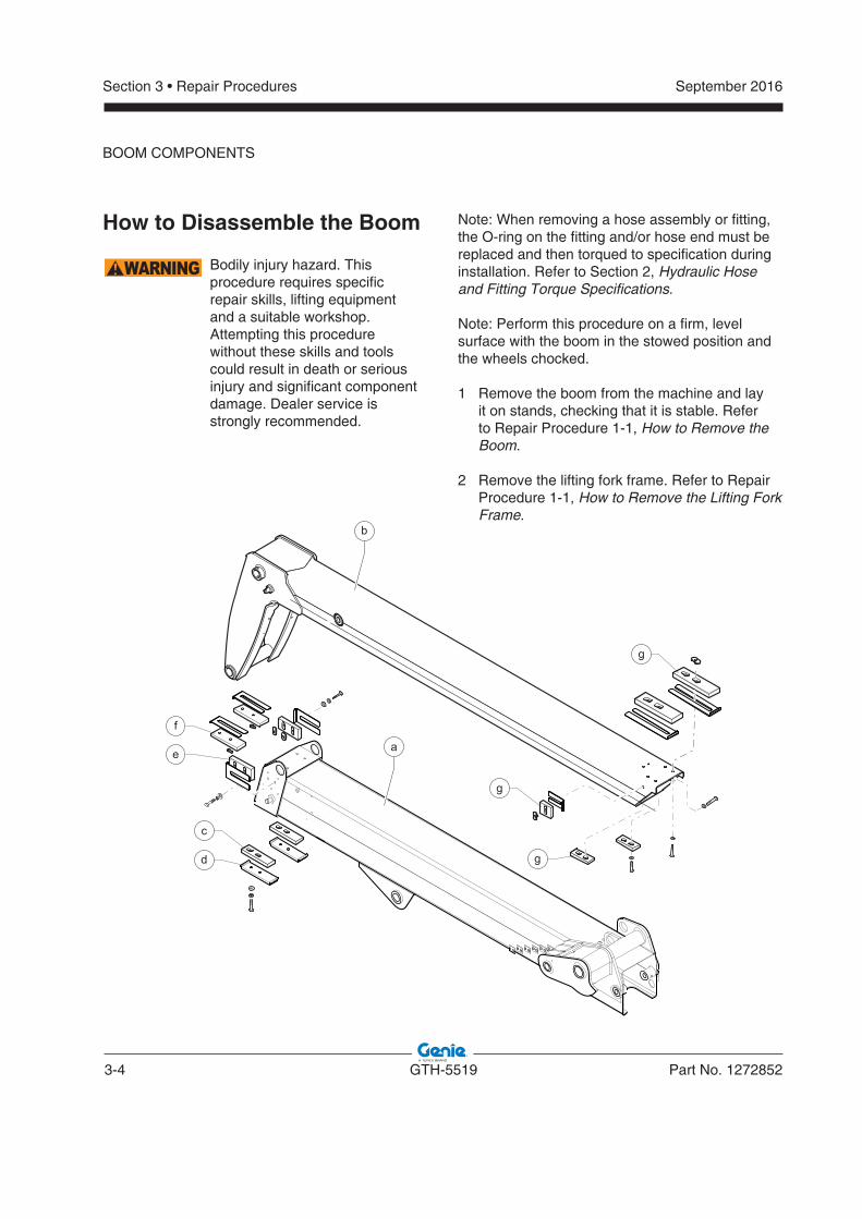
How to Disassemble the Boom
WARNING Bodily injury hazard. This procedure requires specific repair skills, lifting equipment and a suitable workshop. Attempting this procedure without these skills and tools could result in death or serious injury and significant component damage. Dealer service is strongly recommended.
Note: When removing a hose assembly or fitting, the O-ring on the fitting and/or hose end must be replaced and then torqued to specification during installation. Refer to Section 2, Hydraulic Hose and Fitting Torque Specifications.
Note: Perform this procedure on a firm, level surface with the boom in the stowed position and the wheels chocked.
1 1 Remove the boom from the machine and lay Remove the boom from the machine and lay it on stands, checking that it is stable. it on stands, checking that it is stable. Refer to Repair Procedure 1-1, How to Remove the How to Remove the BoomBoom..
2 Remove the lifting fork frame. Refer to Repair Procedure 1-1, HowHow to Remove the Lifting Fork Frame.
BOOM COMPONENTS
b
a
d
c
e
f
g
g
g
September 2016
Part No. 1272852 GTH-5519 3-5
Section 3 • Repair Procedures
BOOM COMPONENTS
3 3 Remove the hydraulic hoses from inside the Remove the hydraulic hoses from inside the boom. boom. Refer to Repair Procedure 1-5, How to How to Replace the Fork Tilt Cylinder HosesReplace the Fork Tilt Cylinder Hoses..
4 4 Remove the extend cylinder from inside the Remove the extend cylinder from inside the boom. boom. Refer to Repair Procedure 1-3, How to How to Remove the Extend CylinderRemove the Extend Cylinder..
5 5 Remove the fork tilt cylinder. Remove the fork tilt cylinder. Refer to Repair Procedure 1-5, How to Remove the Fork Tilt How to Remove the Fork Tilt CylinderCylinder..
6 6 Attach a lifting strap to the front of section "Attach a lifting strap to the front of section "bb", ", raise it slightly from section "raise it slightly from section "aa" then extend it " then extend it by 8-12 in / 20-30 cm.by 8-12 in / 20-30 cm.
7 7 Remove the bottom pads "Remove the bottom pads "cc" and the pad " and the pad supports "supports "dd" from the first boom section." from the first boom section.
8 8 Release the lifting strap to lay the second Release the lifting strap to lay the second section "section "bb" on the first section "" on the first section "aa".".
9 9 Remove the lateral pads "Remove the lateral pads "ee" and the top pads " and the top pads ""ff" from the first section." from the first section.
10 10 Raise again the second section and pull it out Raise again the second section and pull it out slowly from the first one; be careful not to make slowly from the first one; be careful not to make it come out completely.it come out completely.
DANGER Ensure that the second section remains inside the first one and does not come out.
11 11 Attach another lifting straps to the second Attach another lifting straps to the second boom section. Pull the section out and handle boom section. Pull the section out and handle very slowly, paying attention to the position of very slowly, paying attention to the position of the straps to make sure the section is always the straps to make sure the section is always horizontal. horizontal.
12 12 Once removed, place the second boom Once removed, place the second boom sections on a stand suitably positioned. sections on a stand suitably positioned.
13 13 Remove all pads "Remove all pads "gg" from the second section " from the second section ""bb".".
14 14 Remove the pipes from the first boom section Remove the pipes from the first boom section ""aa".".
3-6 GTH-5519 Part No. 1272852
September 2016Section 3 • Repair Procedures
1-2Boom Lift Cylinder
How to Remove the Lift Cylinder
Note: When removing a hose assembly or fitting, the O-ring on the fitting and/or hose end must be replaced and then torqued to specification during installation. Refer to Section 2, Hydraulic Hose and Fitting Torque Specifications.
1 1 Lift the boom until the pin locking the lift Lift the boom until the pin locking the lift cylinder - rod side - is in a position above the cylinder - rod side - is in a position above the cab roof. .cab roof. .
2 2 Attach a lifting strap from an overhead 22045 Attach a lifting strap from an overhead 22045 lbs / 10,000 kg crane to the fork end of the lbs / 10,000 kg crane to the fork end of the boom. Support the boom. Do not apply any boom. Support the boom. Do not apply any lifting pressure.lifting pressure.
3 3 Tag, disconnect and plug the hydraulic hoses Tag, disconnect and plug the hydraulic hoses connected to the shut-off valve. Cap the fittings.connected to the shut-off valve. Cap the fittings.
WARNING Bodily injury hazard. Sprayinghydraulic oil can penetrate and burn skin. Loosen hydraulic connections very slowly to allow the oil pressure to dissipate gradually. Do not allow oil tosquirt or spray.
NOTICE Component damage hazard.Hoses can be damaged if they are kinked or pinched.
4 4 Attach a lifting strap from an overhead crane Attach a lifting strap from an overhead crane to the rod end of the lift cylinder. Support the to the rod end of the lift cylinder. Support the cylinder. Do not apply any lifting pressure.cylinder. Do not apply any lifting pressure.
5 5 Place a suitably dimensioned wooden block Place a suitably dimensioned wooden block before the hydraulic oil tank. This block will be before the hydraulic oil tank. This block will be used to support the weight of the lift cylinder used to support the weight of the lift cylinder first, and the boom afterwards. first, and the boom afterwards.
6 Remove the fasteners securing the lift cylinder rod-end pivot pin to the boom.
DANGER Crushing hazard. The boom will fall if not properly supported when the pivot pin is removed from the machine.
7 7 Lower the lift cylinder and place it on the Lower the lift cylinder and place it on the wooden block previously positioned.wooden block previously positioned.
8 Remove the fasteners securing the lift cylinder barrel-end pivot pin to the chassis.
9 Use a soft metal drift to remove the pivot pin.
10 Remove the cylinder from the machine.
DANGER Crushing hazard. The cylinder could fall if not properly supported when removed from the machine.
11 Using the overhead crane, raise and place the boom on the wooden block suitably positioned.
BOOM COMPONENTS
September 2016
Part No. 1272852 GTH-5519 3-7
Section 3 • Repair Procedures
BOOM COMPONENTS
1-3Boom Extend Cylinder
How to Remove the ExtendCylinder
Note: When removing a hose assembly or fitting, the O-ring on the fitting and/or hose end must be replaced and then torqued to specification during installation. Refer to Section 2, Hydraulic Hose and Fitting Torque Specifications.
1 Raise the boom to a horizontal position.
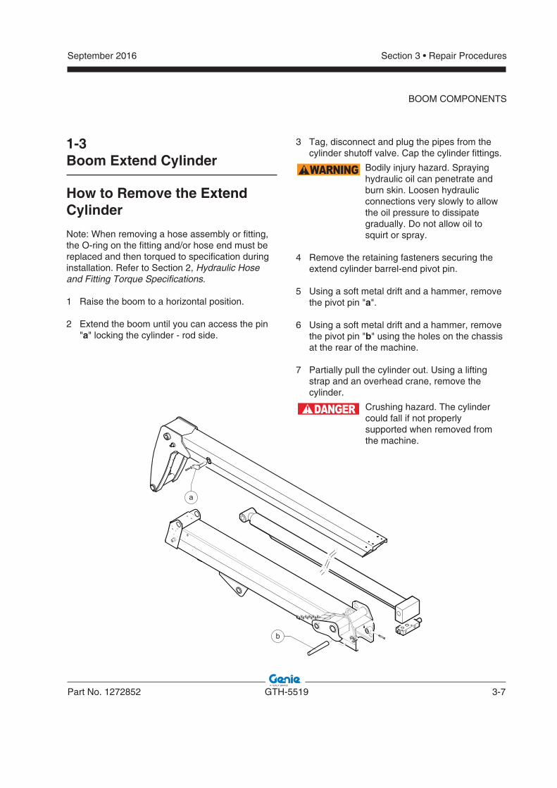
2 2 Extend the boom until you can access the pin Extend the boom until you can access the pin ""aa" locking the cylinder - rod side." locking the cylinder - rod side.
3 Tag, disconnect and plug the pipes from the cylinder shutoff valve. Cap the cylinder fittings.
WARNING Bodily injury hazard. Sprayinghydraulic oil can penetrate and burn skin. Loosen hydraulic connections very slowly to allow the oil pressure to dissipate gradually. Do not allow oil tosquirt or spray.
4 Remove the retaining fasteners securing the extend cylinder barrel-end pivot pin.
5 Using a soft metal drift and a hammer, remove the pivot pin "a".
6 Using a soft metal drift and a hammer, remove the pivot pin "b" using the holes on the chassis using the holes on the chassis at the rear of the machine.at the rear of the machine.
7 Partially pull the cylinder out. Using a lifting strap and an overhead crane, remove the cylinder.
DANGER Crushing hazard. The cylinder could fall if not properly supported when removed from the machine.
a
b
3-8 GTH-5519 Part No. 1272852
September 2016Section 3 • Repair Procedures
1-4Fork Level Cylinder
How to Remove the Fork Level Cylinder
Note: When removing a hose assembly or fitting, the O-ring on the fitting and/or hose end must be replaced and then torqued to specification during installation. Refer to Section 2, Hydraulic Hose and Fitting Torque Specifications.
1 Remove the retaining fasteners securing the level cylinder rod end pivot pin.
2 Using a soft metal drift and a hammer, remove the pivot pin.
3 Using a lifting strap and an overhead crane, support the cylinder.
4 Place a container of suitable size under the hydraulic hoses before disconnecting.
5 Tag, disconnect and plug the hydraulic hoses from the level cylinder. Cap the cylinder fittings.
WARNING Bodily injury hazard. Sprayinghydraulic oil can penetrate and burn skin. Loosen hydraulic connections very slowly to allow the oil pressure to dissipate gradually. Do not allow oil tosquirt or spray.
NOTICE Component damage hazard.Hoses can be damaged if they are kinked or pinched.
BOOM COMPONENTS
6 Remove the retaining fasteners securing the level cylinder barrel end pivot pin.
7 Using a soft metal drift and a hammer, remove the pivot pin using the holes on the chassis on using the holes on the chassis on the rear left side of the machine.the rear left side of the machine.
8 Carefully lift and remove the cylinder from the machine.
DANGER Crushing hazard. The cylinder could fall if not properly supported when removed from the machine.
September 2016
Part No. 1272852 GTH-5519 3-9
Section 3 • Repair Procedures
BOOM COMPONENTS
1-5Fork Tilt Cylinder
How to Remove the Fork TiltCylinder
Note: When removing a hose assembly or fitting, the O-ring on the fitting and/or hose end must be replaced and then torqued to specification during installation. Refer to Section 2, Hydraulic Hose and Fitting Torque Specifications.
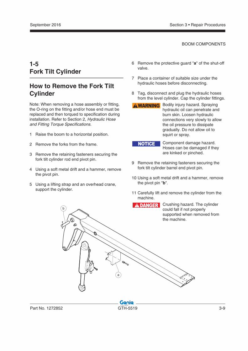
1 Raise the boom to a horizontal position.
2 Remove the forks from the frame.
3 Remove the retaining fasteners securing the fork tilt cylinder rod end pivot pin.
4 Using a soft metal drift and a hammer, remove the pivot pin.
5 Using a lifting strap and an overhead crane, support the cylinder.
6 6 Remove the protective guard "Remove the protective guard "aa" of the shut-off " of the shut-off valve.valve.
7 Place a container of suitable size under the hydraulic hoses before disconnecting.
8 Tag, disconnect and plug the hydraulic hoses from the level cylinder. Cap the cylinder fittings.
WARNING Bodily injury hazard. Sprayinghydraulic oil can penetrate and burn skin. Loosen hydraulic connections very slowly to allow the oil pressure to dissipate gradually. Do not allow oil tosquirt or spray.
NOTICE Component damage hazard.Hoses can be damaged if they are kinked or pinched.
9 Remove the retaining fasteners securing the fork tilt cylinder barrel end pivot pin.
10 Using a soft metal drift and a hammer, remove the pivot pin "b".
11 Carefully lift and remove the cylinder from the machine.
DANGER Crushing hazard. The cylinder could fall if not properly supported when removed from the machine.
b
a
3-10 GTH-5519 Part No. 1272852
September 2016Section 3 • Repair Procedures
BOOM COMPONENTS
How to Replace the Fork Tilt Cylinder Hoses
Note: When removing a hose assembly or fitting, the O-ring on the fitting and/or hose end must be replaced and then torqued to specification during installation. Refer to Section 2, Hydraulic Hose and Fitting Torque Specifications.
1 1 Start the engine.Start the engine.
2 2 Raise the boom to a horizontal position.Raise the boom to a horizontal position.
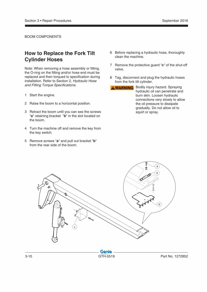
3 3 Retract the boom until you can see the screws Retract the boom until you can see the screws ""aa" retaining bracket "" retaining bracket "bb" in the slot located on " in the slot located on the boom.the boom.
4 4 Turn the machine off and remove the key from Turn the machine off and remove the key from the key switch.the key switch.
5 5 Remove screws "Remove screws "aa" and pull out bracket "" and pull out bracket "bb" " from the rear side of the boom.from the rear side of the boom.
6 6 Before replacing a hydraulic hose, thoroughly Before replacing a hydraulic hose, thoroughly clean the machine.clean the machine.
7 7 Remove the protective guard "Remove the protective guard "cc" of the shut-off " of the shut-off valve.valve.
8 Tag, disconnect and plug the hydraulic hoses from the fork tilt cylinder.
WARNING Bodily injury hazard. Sprayinghydraulic oil can penetrate and burn skin. Loosen hydraulic connections very slowly to allow the oil pressure to dissipate gradually. Do not allow oil tosquirt or spray.
d
a
b
c
September 2016
Part No. 1272852 GTH-5519 3-11
Section 3 • Repair Procedures
BOOM COMPONENTS
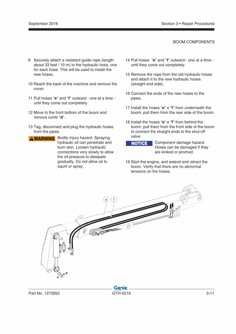
9 9 Securely attach a resistant guide rope (length Securely attach a resistant guide rope (length about 33 feet / 10 m) to the hydraulic hose, one about 33 feet / 10 m) to the hydraulic hose, one for each hose. This will be used to install the for each hose. This will be used to install the new hoses.new hoses.
10 10 Reach the back of the machine and remove the Reach the back of the machine and remove the cover.cover.
11 11 Pull hoses "Pull hoses "ee" and "" and "ff" outward - one at a time - " outward - one at a time - until they come out completely.until they come out completely.
12 12 Move to the front bottom of the boom and Move to the front bottom of the boom and remove comb "remove comb "dd".".
13 13 Tag, disconnect and plug the hydraulic hoses Tag, disconnect and plug the hydraulic hoses from the pipes.from the pipes.
WARNING Bodily injury hazard. Sprayinghydraulic oil can penetrate and burn skin. Loosen hydraulic connections very slowly to allow the oil pressure to dissipate gradually. Do not allow oil tosquirt or spray.
e f
14 14 Pull hoses "Pull hoses "ee" and "" and "ff" outward - one at a time - " outward - one at a time - until they come out completely.until they come out completely.
15 15 Remove the rope from the old hydraulic hoses Remove the rope from the old hydraulic hoses and attach it to the new hydraulic hoses and attach it to the new hydraulic hoses (straight end side). (straight end side).
16 16 Connect the ends of the new hoses to the Connect the ends of the new hoses to the pipes. pipes.
17 17 Install the hoses "Install the hoses "ee" e "" e "ff" from underneath the " from underneath the boom: pull them from the rear side of the boom.boom: pull them from the rear side of the boom.
18 18 Install the hoses "Install the hoses "ee" e "" e "ff" from behind the " from behind the boom: pull them from the front side of the boom boom: pull them from the front side of the boom to connect the straight ends to the shut-off to connect the straight ends to the shut-off valve.valve.
NOTICE Component damage hazard.Hoses can be damaged if they are kinked or pinched.
19 19 Start the engine, and extend and retract the Start the engine, and extend and retract the boom. Verify that there are no abnormal boom. Verify that there are no abnormal tensions on the hoses. tensions on the hoses.
3-12 GTH-5519 Part No. 1272852
September 2016Section 3 • Repair Procedures
2-1Operator's Compartment
How to Remove the Operator'sCompartment
The operator's compartment is used to activate machine functions while sitting in the operator's drivers seat.
Within the operator's compartment there is a transmission column shifter, steering selector, 4-way controller, accelerator pedal and brake pedal. All of these components are replaceable.
For further information or assistance, consult the Genie Service Department.
WARNING Bodily injury hazard. This procedure requires specific repair skills, lifting equipment and a suitable workshop. Attempting this procedure without these skills and tools could result in death or serious injury and significant component damage. Dealer service is required.
1 Start the diesel engine and raise the boom above the cab.
2 Open the engine cover and disconnect the and disconnect the battery negative (-) terminal.battery negative (-) terminal.
WARNING Electrocution/burn hazard. Contact with electrically charged circuits could result in death or serious injury. Remove all rings, watches and other jewelry.
3 Remove the protective cover next to the cab - inner side of the machine.
4 Cut the plastic fasteners fixing the electrical cables, then disconnect all of the electrical wires.
5 5 Tag, disconnect and plug the hydraulic lines Tag, disconnect and plug the hydraulic lines of: power steering, power steering delivery, of: power steering, power steering delivery, solenoid valve delivery, tank draining, brake solenoid valve delivery, tank draining, brake pump, power steering delivery from pump, pump, power steering delivery from pump, joystick (no.6).joystick (no.6).
WARNING Bodily injury hazard. Sprayinghydraulic oil can penetrate and burn skin. Loosen hydraulic connections very slowly to allow the oil pressure to dissipate gradually. Do not allow oil tosquirt or spray.
6 Tag, disconnect and plug the heater lines (n.2 hoses).
7 Disconnect the ground wire.
8 Remove the 4 retaining fasteners of the cabin.
9 Install and secure two eyebolts to the top the cabin in the special seats.
Operator's Compartment
September 2016
Part No. 1272852 GTH-5519 3-13
Section 3 • Repair Procedures
OPERATOR'S COMPARTMENT
10 Using a sling chain and an overhead crane, slowly raise the cabin away from the machine and set it on a supporting device.
NOTICE Component damage hazard.Wrapping a strap around the cab and lifting using an overhead crane can put excessive pressure on the glass windows of the cab, causing the windows to break. Do not lift the cab using a strap from an overhead crane.
Bolt torque specifi cation
Operator's cab mounting bolts 155 ft-lbs210 Nm
(plus Locktite compound)
3-14 GTH-5519 Part No. 1272852
September 2016Section 3 • Repair Procedures
OPERATOR'S COMPARTMENT
How to Remove the SteeringWheel
1 1 Open the engine cover and disconnect the Open the engine cover and disconnect the battery negative (-) terminal.battery negative (-) terminal.
WARNING Electrocution/burn hazard. Contact with electrically charged circuits could result in death or serious injury. Remove all rings, watches and other jewelry.
2 Remove the horn button from the steering wheel. Remove the nut securing the steering wheel to the column and remove the steering wheel.
2-2Machine Controls
How to Remove the SteeringColumn
1 Open the engine cover and disconnect the en the engine cover and disconnect the battery negative (-) terminal.battery negative (-) terminal.
WARNING Electrocution/burn hazard. Contact with electrically charged circuits could result in death or serious injury. Remove all rings, watches and other jewelry.
2 Remove the rear steering column cover.
3 Remove the lower part of the dashboard.
4 Remove the transmission control lever.
5 Remove the light control lever (if present).
6 Remove the screws which secure the steering column to the frame.
7 Remove the steering column.
September 2016
Part No. 1272852 GTH-5519 3-15
Section 3 • Repair Procedures
OPERATOR'S COMPARTMENT
How to Remove the SteerRotation Actuator
1 Remove the steering column. See 2-2, How to Remove the Steering Column.
2 Working under the dashboard, locate the hydraulic hoses of the steer rotation actuator.
3 Tag, disconnect and cap the hydraulic hoses and steer rotation actuator holes.
WARNING Bodily injury hazard. Sprayinghydraulic oil can penetrate and burn skin. Loosen hydraulic connections very slowly to allow the oil pressure to dissipate gradually. Do not allow oil tosquirt or spray.
4 Remove the steer rotation actuator.
3-16 GTH-5519 Part No. 1272852
September 2016Section 3 • Repair Procedures
OPERATOR'S COMPARTMENT
How to Remove the Joystick
1 1 Lift the boom.Lift the boom.
2 2 Remove the guard underneath the boom that is Remove the guard underneath the boom that is located in the central part in the machine.located in the central part in the machine.
3 3 Open the engine cover and disconnect the Open the engine cover and disconnect the battery negative (-) terminal.battery negative (-) terminal.
WARNING Electrocution/burn hazard. Contact with electrically charged circuits could result in death or serious injury. Remove all rings, watches and other jewelry.
4 4 Raise the joystick protective guard.Raise the joystick protective guard.
5 5 Remove the retaining fasteners that secure the Remove the retaining fasteners that secure the joystick to the mount panel.joystick to the mount panel.
6 6 Reach the center of the machine, next to the Reach the center of the machine, next to the cab.cab.
7 Tag and disconnect the joystick harness connector from the machine.
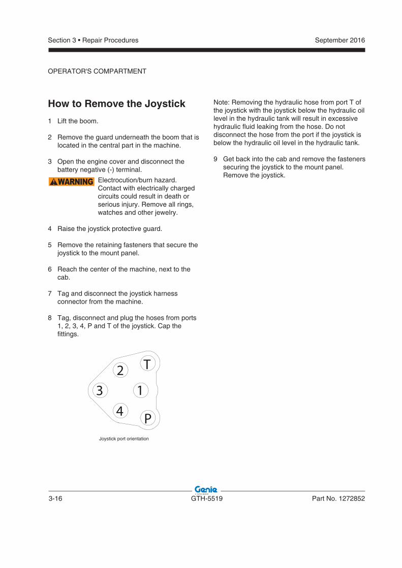
8 Tag, disconnect and plug the hoses from ports 1, 2, 3, 4, P and T of the joystick. Cap the fittings.
T
P
14
32
Joystick port orientation
Note: Removing the hydraulic hose from port T of the joystick with the joystick below the hydraulic oil level in the hydraulic tank will result in excessive hydraulic fluid leaking from the hose. Do not disconnect the hose from the port if the joystick is below the hydraulic oil level in the hydraulic tank.
9 9 Get back into the cab and remove the fasteners Get back into the cab and remove the fasteners securing the joystick to the mount panel. securing the joystick to the mount panel. Remove the joystick.Remove the joystick.
September 2016
Part No. 1272852 GTH-5519 3-17
Section 3 • Repair Procedures
How to Remove the Brake Pedal Assembly
1 Remove the front dashboard, lower part.
2 2 Open the engine cover and disconnect the Open the engine cover and disconnect the battery negative (-) terminal.battery negative (-) terminal.
WARNING Electrocution/burn hazard. Contact with electrically charged circuits could result in death or serious injury. Remove all rings, watches and other jewelry.
3 3 Remove the retaining fasteners securing the Remove the retaining fasteners securing the brake pump to the support.brake pump to the support.
4 Tag and disconnect the brake harness.
5 Tag, disconnect and plug the hydraulic hoses of the brake pedal pump.
WARNING Bodily injury hazard. Sprayinghydraulic oil can penetrate and burn skin. Loosen hydraulic connections very slowly to allow the oil pressure to dissipate gradually. Do not allow oil tosquirt or spray.
6 Remove the pin securing the brake pedal to the brake pump support. Remove the brake pedal.
How to Remove the GaugeCluster Assembly
1 1 Open the engine cover and disconnect the Open the engine cover and disconnect the battery negative (-) terminal.battery negative (-) terminal.
WARNING Electrocution/burn hazard. Contact with electrically charged circuits could result in death or serious injury. Remove all rings, watches and other jewelry.
2 2 Remove the front dashboard, lower part.Remove the front dashboard, lower part.
3 3 Remove the retaining fasteners securing the Remove the retaining fasteners securing the gauge cluster.gauge cluster.
4 4 Tag and disconnect the wire harness from the Tag and disconnect the wire harness from the gauge cluster. Remove the gauge cluster from gauge cluster. Remove the gauge cluster from the machine.the machine.
OPERATOR'S COMPARTMENT
3-18 GTH-5519 Part No. 1272852
September 2016Section 3 • Repair Procedures
3-1Fuel Tank
How to Remove the Fuel Tank
DANGER Explosion and fire hazard. Engine fuels are combustible. Remove the fuel tank in an open, wellventilated area away from heaters, sparks, flames and lighted tobacco. Always have anapproved fire extinguisher within easy reach.
DANGER Explosion and fire hazard. Neverdrain or store fuel in an open container due to the possibility of fire.
DANGER Explosion and fire hazard. When transferring fuel, connect a grounding wire between the machine and pump or container.
WARNING Bodily injury hazard. This procedure requires specific repair skills, lifting equipment and a suitable workshop. Attempting this procedure without these skills and tools could result in death or serious injury and significant component damage. Dealer service is strongly recommended.
1 Open the engine cover and disconnect the and disconnect the battery negative (-) terminal.battery negative (-) terminal.
WARNING Electrocution/burn hazard. Contact with electrically charged circuits could result in death or serious injury. Remove all rings, watches and other jewelry.
2 2 Reach the rear side of the machine and remove Reach the rear side of the machine and remove the counterweight and the rear cover..the counterweight and the rear cover..
3 3 Move to the center of the machine.Move to the center of the machine.
4 Tag and disconnect the wire harness from the fuel level terminals.
5 5 Disconnect the ground wireDisconnect the ground wire.
6 Remove the filler cap from the fuel tank.
7 Using an approved hand-operated pump, drain the fuel tank into a container of suitable capacity. Refer to Section 2, Specifications.
WARNING Explosion and fire hazard. Whentransferring fuel, connect a grounding wire between the machine and pump or container.
Be sure to only use a hand operated pump suitable for use with gasoline and/or diesel fuel.
8 Loosen all the clamps and pull out the hoses.
9 Remove the retaining fasteners securing the tanks to the machine.
10 10 Remove the tank from the machine.Remove the tank from the machine.
NOTICE The reduced weight of the empty The reduced weight of the empty tank makes it possible to handle tank makes it possible to handle it manually.it manually.
Fuel and Hydraulic Tanks
September 2016
Part No. 1272852 GTH-5519 3-19
Section 3 • Repair Procedures
FUEL AND HYDRAULIC TANKS
3-2Hydraulic Tank
How to Remove the Hydraulic Tank
WARNING Bodily injury hazard. This procedure requires specific repair skills, lifting equipment and a suitable workshop. Attempting this procedure without these skills and tools could result in death or serious injury and significant component damage. Dealer service is strongly recommended.
1 1 Lift the boom.Lift the boom.
2 Open the engine cover and disconnect the and disconnect the battery negative (-) terminal.battery negative (-) terminal.
WARNING Electrocution/burn hazard. Contact with electrically charged circuits could result in death or serious injury. Remove all rings, watches and other jewelry.
3 Close the oil intake valve.
4 Remove the filler cap from the hydraulic tank.
5 Place a drain pan or other suitable container under the hydraulic tank. Refer to Section 2, Specifications.
6 Remove the drain plug from the hydraulic tank and completely drain the tank.
CAUTION Bodily injury hazard. Beware of hot oil. Contact with hot oil may cause severe burns.
7 Go under the machine and remove the drive shaft.
8 Loosen all the clamps and pull out the hoses.
9 Disconnect the electrical harnesses.
10 Remove the wire harness from bulb on the hydraulic filter.
11 Place a container of suitable size under the hydraulic hoses before disconnecting.
NOTICE Used oils must be handled and disposed of according to local regulations.
12 Disconnect all hydraulic hoses.
13 13 Loosen the bottom clamp and disconnect the Loosen the bottom clamp and disconnect the oil fill hose.oil fill hose.
14 Attach a lifting strap from an overhead crane to the lifting points of the tank.
DANGER Crushing hazard. The tank could become unbalanced and fall if not properly supported when removed from the machine.
15 Remove the retaining fasteners securing the tanks to the machine.
16 16 Lift the tank slightly and push it forward Lift the tank slightly and push it forward manually, until you can lower it on the ground.manually, until you can lower it on the ground.
3-20 GTH-5519 Part No. 1272852
September 2016Section 3 • Repair Procedures
Engines
4-2Engine Fault Codes
How to Retrieve Engine FaultCodes
When the engine Electronic Control Module (ECM) detects an abnormal operating condition, a fault code is immediately stored in the ECM memory. At the same time, a colored warning lamp is illuminated and the fault code is shown on the engine diagnostic display, located on the dashboard in the operator's compartment.
To learn the specifications of and how to use the fault codes, refer to Section 5, Fault Codes.
4-1Engines
How to Repair theDeutz TD 2.9 L4 Engine
Repair procedures and additional engine information is available in theDeutz TD 2.9 L4 Workshop Manual(Deutz part number 03123982).
Deutz TD 2.9 L4 Workshop Manual
Genie part number 57.4700.0022
September 2016
Part No. 1272852 GTH-5519 3-21
Section 3 • Repair Procedures
Axle
5-1Axle
How to Remove the AxleWARNING Bodily injury hazard. This
procedure requires specific repair skills, lifting equipment and a suitable workshop. Attempting this procedure without these skills and tools could result in death or serious injury and significant component damage. Dealer service is required.
1 Chock the wheels.
2 Remove the fasteners securing the driveshaft to the axle. Remove the driveshaft from the machine.
3 Tag and remove the hydraulic hoses from the axle.
WARNING Bodily injury hazard. Sprayinghydraulic oil can penetrate and burn skin. Loosen hydraulic connections very slowly to allow the oil pressure to dissipate gradually. Do not allow oil tosquirt or spray.
4 Loosen the lug nuts of both wheels on the axle to be removed. Do not remove the lug nuts.
5 Raise the end of the machine until the tires are off the ground. Place blocks under the chassis for support.
WARNING Crushing hazard. The chassis will fall if not properly supported.
6 Remove the lug nuts. Remove the tire and wheel assembly from both ends of the axle.
7 Support and secure the axle to an appropriate lifting device.
8 Use a soft metal drift to remove the pivot pin.
9 Remove the fasteners securing the axle to the chassis. Remove the axle from the machine.
WARNING Crushing hazard. The axle will fall if not properly supported when the fasteners are removed from the machine.
Bolt torque specifi cation
Axle mounting bolts 515 ft-lbs700 Nm
3-22 GTH-5519 Part No. 1272852
September 2016Section 3 • Repair Procedures
Hydraulic Pumps
6-1Boom and Steering Function Pump
How to Test the Boom and Steering Function Pump
1 Connect a 0 to 5000 psi / 0 to 350 bar pressure gauge to port TP1.
2 Start the engine.
3 Increase the engine speed to maximum rpm.
4 Activate and hold boom retract.
5 Without releasing the joystick, keep pushing the throttle pedal.
Result: the pressure gauge reads 3915 psi / 270 bar. The pump is good.
Pressure is not within specification. The pump needs to be adjusted OR the pump
or pump coupling is faulty and needs to be serviced or replaced.
NOTICE Component damage hazard. There is no relief valve in the hydraulic pump and the pump can be damaged if the pressure is allowed to exceed specification. When testing the pump, crank the engine in one second intervals until the correct pressure is confirmed. Do not over-pressurize the pump.
6 Remove the pressure gauge and install plug onto port TP1.
September 2016
Part No. 1272852 GTH-5519 3-23
Section 3 • Repair Procedures
How to Remove the Boom and Steering Function PumpWARNING Bodily injury hazard. This
procedure requires specific repair skills, lifting equipment and a suitable workshop. Attempting this procedure without these skills and tools could result in death or serious injury and significant component damage. Dealer service is strongly recommended.
Note: When removing a hose assembly or fitting, the fitting and/or hose end must be torqued to specification during installation. Refer to Section 2, Hydraulic Hose and Fitting Torque Specifications.
Note: Perform this procedure with the engine off and cool to the touch.
1 Close the hydraulic tank ball valve.
2 Open the engine cover and disconnect the and disconnect the battery negative (-) terminal.battery negative (-) terminal.
WARNING Electrocution/burn hazard. Contact with electrically charged circuits could result in death or serious injury. Remove all rings, watches and other jewelry.
3 Remove the cover that is under engine.
4 Tag, disconnect and plug the hoses located at the right side of the pump. Cap the fitting on the pump.
WARNING Bodily injury hazard. Sprayinghydraulic oil can penetrate and burn skin. Loosen hydraulic connections very slowly to allow the oil pressure to dissipate gradually. Do not allow oil tosquirt or spray.
5 Tag, disconnect and plug the hydraulic pump supply hose at the pump, located at the left side of the pump. Cap the fitting on the pump.
Note: Placing the open end of the case drain hose below the hydraulic oil level in the hydraulic tank will result in excessive hydraulic fluid leaking from the hose. Do not lower the open end of the case drain hose below the fluid level of the hydraulic tank until the hose is plugged.
6 Remove the fasteners securing the pump, then remove the pump by pulling it to the front of the machine.
WARNING Crushing hazard. The pump will fall if not properly supported when the fasteners are removed from the machine.
HYDRAULIC PUMPS
3-24 GTH-5519 Part No. 1272852
September 2016Section 3 • Repair Procedures
How to Install the Boom and Steering Function PumpWARNING Bodily injury hazard. This
procedure requires specific repair skills, lifting equipment and a suitable workshop. Attempting this procedure without these skills and tools could result in death or serious injury and significant component damage. Dealer service is strongly recommended.
Note: When removing a hose assembly or fitting, the fitting and/or hose end must be torqued to specification during installation. Refer to Section 2, Hydraulic Hose and Fitting Torque Specifications.
Note: Perform this procedure with the engine off and cool to the touch.
1 1 Open the engine cover.Open the engine cover.
2 Remove the cover that is under engine.
3 Install the boom function pump on the engine.
4 Install the hoses onto the pump. Install the hoses retaining rings and fasteners.
WARNING Bodily injury hazard. Sprayinghydraulic oil can penetrate and burn skin. Loosen hydraulic connections very slowly to allow the oil pressure to dissipate gradually. Do not allow oil tosquirt or spray.
5 Open the hydraulic tank ball valve.
HYDRAULIC PUMPS
6 Check the hydraulic fluid level in the hydraulic tank. Add fluid if needed.
7 Start the engine and prime the pump. See 6-1, How to Prime the Boom and Steering Function Pump.
8 Inspect for leaks.
9 Adjust the pump pressure. See 6-1, How to test the Boom and Steering Function Pump.
September 2016
Part No. 1272852 GTH-5519 3-25
Section 3 • Repair Procedures
HYDRAULIC PUMPS
How to Prime the Boom and Steering Function Pump
1 Start the engine, allow the engine to run at low idle for 15 seconds then shut off the engine.
2 Wait 15 seconds, then start the engine again.
3 Allow the engine to run at low idle for 15 seconds and then shut off the engine.
3-26 GTH-5519 Part No. 1272852
September 2016Section 3 • Repair Procedures
6-2Hydrostatic Transmission Pump
How to Test the Hydrostatic Transmission Pump
Note: Perform this procedure on a firm, level surface, with the boom in the stowed position and service brake pedal engaged.
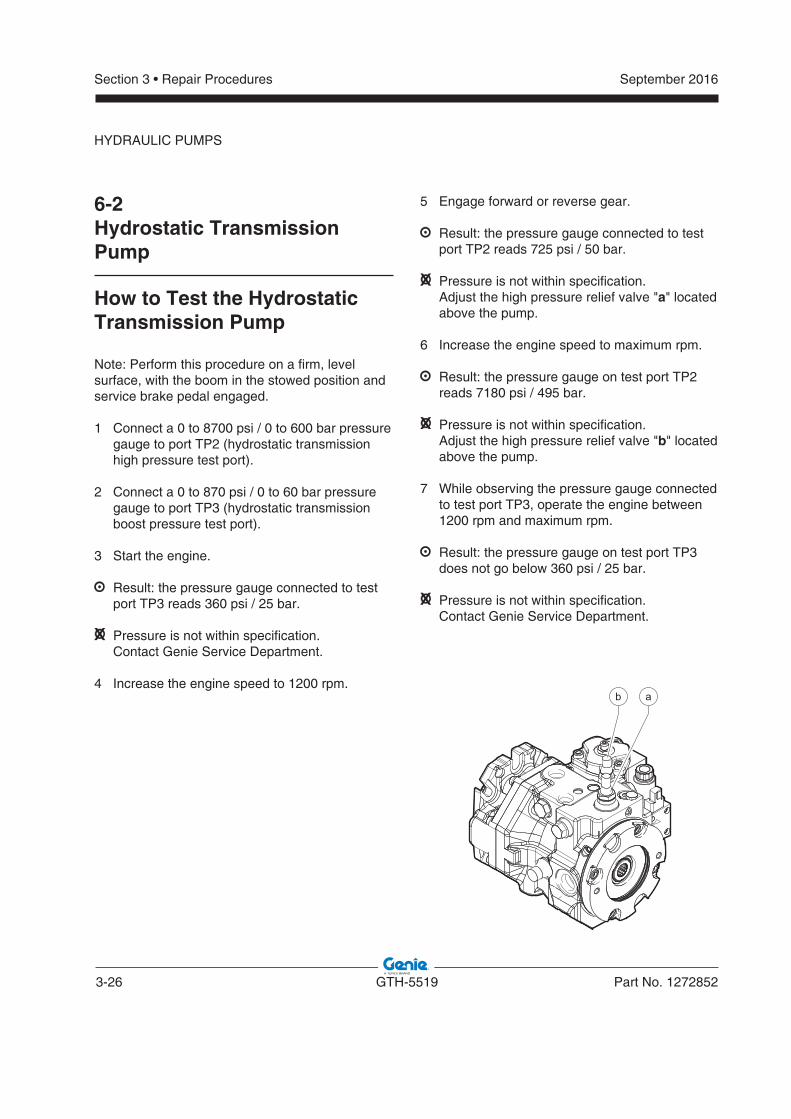
1 Connect a 0 to 8700 psi / 0 to 600 bar pressure gauge to port TP2 (hydrostatic transmission high pressure test port).
2 Connect a 0 to 870 psi / 0 to 60 bar pressure gauge to port TP3 (hydrostatic transmission boost pressure test port).
3 Start the engine.
Result: the pressure gauge connected to test port TP3 reads 360 psi / 25 bar.
Pressure is not within specification. Contact Genie Service Department.
4 Increase the engine speed to 1200 rpm.
5 Engage forward or reverse gear.
Result: the pressure gauge connected to test port TP2 reads 725 psi / 50 bar.
Pressure is not within specification. Adjust the high pressure relief valve "a" located
above the pump.
6 Increase the engine speed to maximum rpm.
Result: the pressure gauge on test port TP2 reads 7180 psi / 495 bar.
Pressure is not within specification. Adjust the high pressure relief valve "b" located
above the pump.
7 While observing the pressure gauge connected to test port TP3, operate the engine between 1200 rpm and maximum rpm.
Result: the pressure gauge on test port TP3 does not go below 360 psi / 25 bar.
Pressure is not within specification. Contact Genie Service Department.
HYDRAULIC PUMPS
b a
September 2016
Part No. 1272852 GTH-5519 3-27
Section 3 • Repair Procedures
How to Remove the Hydrostatic Transmission PumpWARNING Bodily injury hazard. This
procedure requires specific repair skills, lifting equipment and a suitable workshop. Attempting this procedure without these skills and tools could result in death or serious injury and significant component damage. Dealer service is strongly recommended.
Note: When removing a hose assembly or fitting, the fitting and/or hose end must be torqued to specification during installation. Refer to Section 2, Hydraulic Hose and Fitting Torque Specifications.
Note: Perform this procedure with the engine off and cool to the touch.
1 Open the engine compartment.
2 Remove the cover that is under engine.
3 3 Disconnect the battery negative (-) terminal.Disconnect the battery negative (-) terminal.
4 Tag, disconnect and plug the hoses that are connected to the hydrostatic transmission pump. Cap the fittings.
WARNING Bodily injury hazard. Sprayinghydraulic oil can penetrate and burn skin. Loosen hydraulic connections very slowly to allow the oil pressure to dissipate gradually. Do not allow oil tosquirt or spray.
5 Remove the boom and steering function pump from the hydrostatic transmission pump.
6 Tag and disconnect the harness from the transmission.
7 Support and secure the transmission pump to a suitable lifting device. Do not apply lighting pressure.
8 Remove the hydrostatic transmission pump.
WARNING Crushing hazard. The hydrostatic transmission pump will fall if not properly supported when the fasteners are removed from the machine.
HYDRAULIC PUMPS
3-28 GTH-5519 Part No. 1272852
September 2016Section 3 • Repair Procedures
How to Install the Hydrostatic Transmission PumpWARNING Bodily injury hazard. This
procedure requires specific repair skills, lifting equipment and a suitable workshop. Attempting this procedure without these skills and tools could result in death or serious injury and significant component damage. Dealer service is strongly recommended.
Note: When removing a hose assembly or fitting, the fitting and/or hose end must be torqued to specification during installation. Refer to Section 2, Hydraulic Hose and Fitting Torque Specifications.
Note: Perform this procedure with the engine off and cool to the touch.
1 Open the engine compartment.
2 Remove the cover that is under engine.
3 3 Place a suitable support for the pump to install Place a suitable support for the pump to install it from the bottom.it from the bottom.
4 Install the hydrostatic transmission pump on the engine.
5 Remove the fitting caps from the hydrostatic transmission pump.
6 Remove the hoses caps.
7 Connect the hoses to the pump.
WARNING Bodily injury hazard. Sprayinghydraulic oil can penetrate and burn skin. Loosen hydraulic connections very slowly to allow the oil pressure to dissipate gradually. Do not allow oil tosquirt or spray.
8 Connect the harness to the transmission pump.
9 Install the boom and steering function pump on the hydrostatic transmission pump.
10 Start the engine and prime the pump. See 6-2, How to Prime the Hydrostatic Transmission Pump.
11 Inspect for leaks.
12 Adjust the pump pressure. See 6-2, How to test the Hydrostatic Transmission Pump.
HYDRAULIC PUMPS
September 2016
Part No. 1272852 GTH-5519 3-29
Section 3 • Repair Procedures
How to Prime the Hydrostatic Transmission PumpWARNING Bodily injury hazard. This
procedure requires specific repair skills, lifting equipment and a suitable workshop. Attempting this procedure without these skills and tools could result in death or serious injury and significant component damage. Dealer service is strongly recommended.
1 Connect a 0 to 870 psi / 0 to 60 bar pressure gauge to port TP3 (hydrostatic transmission boost pressure test port).
2 Start the engine. Run at low idle for 5 seconds. Shut the engine off and wait for 15 seconds.
3 Start the engine. Run at low idle for 10 seconds. Shut the engine off and wait for 15 seconds.
4 Note: Repeat step 3 until the pressure gauge connected to TP3 reads 360 psi / 25 bar or greater.
5 Apply the brake pedal and start the engine. Shift the transmission into forward and disengage the emergency brake.
6 Release the brake pedal and slowly increase the engine rpm until the machine starts to move. Apply the brake.
7 Shift the transmission into reverse. Release the brake pedal and slowly increase the engine rpm until the machine starts to move. Apply the brake.
8 Engage the emergency brake and turn the engine off. Check for hydraulic leaks.
HYDRAULIC PUMPS
3-30 GTH-5519 Part No. 1272852
September 2016Section 3 • Repair Procedures
7-1Function Manifold
How to Set the Steer Pressure
1 Connect a 0 to 5000 psi / 0 to 350 bar pressure gauge to port TP1 on the function manifold (boom and steering functions hydraulic test port).
2 Start the engine. Allow the engine to idle.
3 Fully turn and hold the steering wheel in the left direction and allow the wheels to fully turn to the left. Continue holding the steering while observing the pressure reading on the pressure gauge.
Result: the pressure gauge reads 2030 psi / 140 bar. The pressure setting is correct. Proceed to step 8.
Pressure is not within specification. The pressure setting needs to be adjusted.
Proceed to step 4.
4 Turn the engine off, spot the valve on the power steering and open the cap.
5 Adjust the internal hex socket. Turn clockwise to increase the pressure; turn counterclockwise to decrease the pressure.
6 Cap the valve.
7 Repeat this procedure beginning with step 2.
8 Turn the machine off. Remove the pressure gauge from the test port.
Manifolds
September 2016
Part No. 1272852 GTH-5519 3-31
Section 3 • Repair Procedures
How to Remove the Function ManifoldWARNING Bodily injury hazard. This
procedure requires specific repair skills, lifting equipment and a suitable workshop. Attempting this procedure without these skills and tools could result in death or serious injury and significant component damage. Dealer service is strongly recommended.
Note: When removing a hose assembly or fitting, the fitting and/or hose end must be torqued to specification during installation. Refer to Section 2, Hydraulic Hose and Fitting Torque Specifications.
Note: Perform this procedure with the engine off and cool to the touch.
1 Close the hydraulic tank ball valve.
2 Remove the central cover of the machine.
3 Remove the lateral cover of cabin.
4 Tag, disconnect and plug the hoses from the function manifold.
WARNING Bodily injury hazard. Sprayinghydraulic oil can penetrate and burn skin. Loosen hydraulic connections very slowly to allow the oil pressure to dissipate gradually. Do not allow oil tosquirt or spray.
5 Support and secure the function manifold to a suitable lifting device. Do not apply lighting pressure.
6 Remove the retaining fasteners securing the function manifold.
7 Remove the function manifold.
WARNING Crushing hazard. The function manifold will fall if not properly supported when the fasteners are removed from the machine.
MANIFOLDS
3-32 GTH-5519 Part No. 1272852
September 2016Section 3 • Repair Procedures
How to Test the Function Manifold
1 Connect a 0 to 5000 psi / 0 to 350 bar pressure gauge to port TP1 (boom and steering functions hydraulic circuit test port).
2 Start the engine.
3 Increase the engine speed to maximum rpm.
4 Moving the joystick, retract the boom.
Result: the pressure gauge reads 3915 psi / 270 bar. The pump is good.
Pressure is not within specification. Adjust the main relief valve placed above the
manifold.
MANIFOLDS
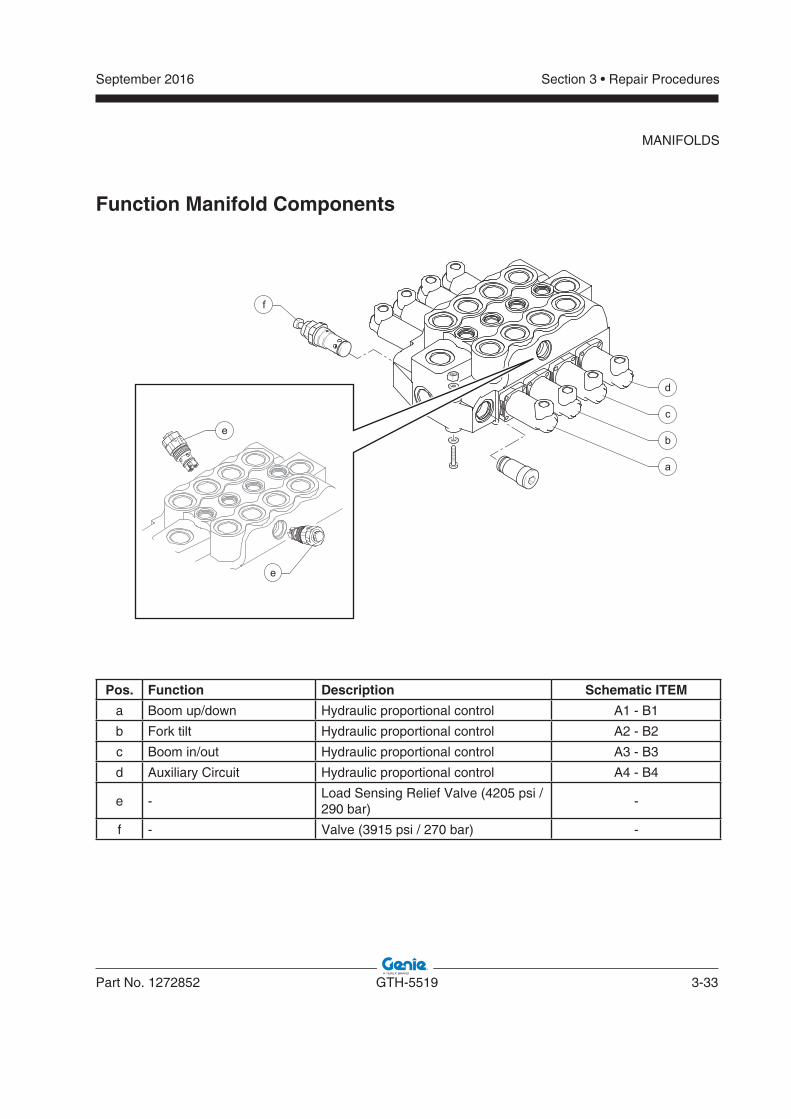
September 2016
Part No. 1272852 GTH-5519 3-33
Section 3 • Repair Procedures
MANIFOLDS
Function Manifold Components
Pos. Function Description Schematic ITEM
a Boom up/down Hydraulic proportional control A1 - B1
b Fork tilt Hydraulic proportional control A2 - B2
c Boom in/out Hydraulic proportional control A3 - B3
d Auxiliary Circuit Hydraulic proportional control A4 - B4
e -Load Sensing Relief Valve (4205 psi / 290 bar)
-
f - Valve (3915 psi / 270 bar) -
e
e
f
d
c
b
a
3-34 GTH-5519 Part No. 1272852
September 2016Section 3 • Repair Procedures
7-2Valve Coils
How to Test a Coil
A properly functioning coil provides an electromagnetic force which operates the solenoid valve. Critical to normal operation is continuity within the coil. Zero resistance or infinite resistance indicates the coil has failed.
Since coil resistance is sensitive to temperature, resistance values outside specification can produce erratic operation. When coil resistance decreases below specification, amperage increases. As resistance rises above specification, voltage increases.
While valves may operate when coil resistance is outside specification, maintaining coils within specification will help ensure proper valve function over a wide range of operating temperatures.
WARNING Electrocution/burn hazard. Contact with electrically charged circuits could result in death or serious injury.Remove all rings, watches and other jewelry.
Note: If the machine has been in operation, allow the coil to cool at least 3 hours before performing this test.
1 Tag and disconnect the wiring from the coil to be tested.
2 Test the coil resistance using a multimeter set to resistance (). Refer to the Valve Coil Resistance Specification table.
Result: If the resistance is not within the adjusted specification, plus or minus 10%, replace the coil.
Valve Coil ResistanceSpecifi cation
Note: The following coil resistance specifications are at an ambient temperature of 68°F / 20°C. As valve coil resistance is sensitive to changes in air temperature, the coil resistance will typically increase or decrease by 4% for each 18°F / 20°C that your air temperature increases or decreases from 68°F / 20°C.
Description Specifi cation
Steering modes selector valve,3 position 4 way12V DC with diode
5.6
Mechanical gear speed Selector valve, 3 position 4 way12V DC with diode
8.8
Forward/Reverse Selector valve, 3 position 4 way12V DC with diode
8.8
Outrigger Selector valve,2 position 4 way12V DC with diode
8.8
MANIFOLDS
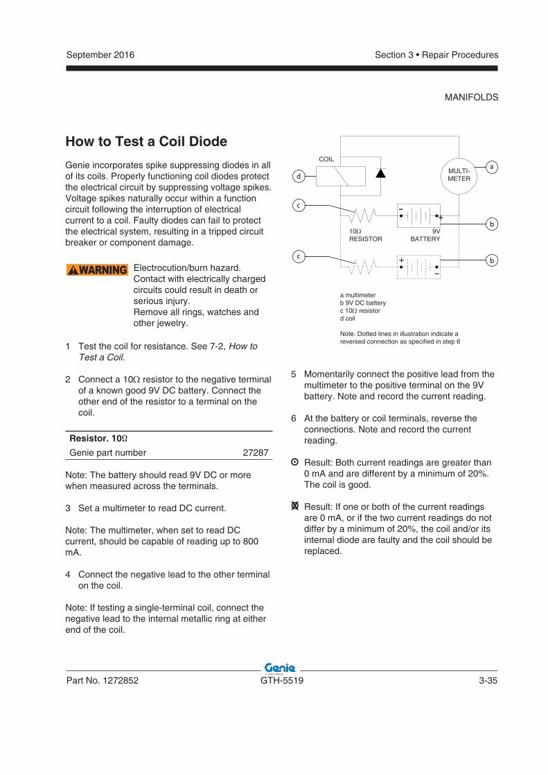
September 2016
Part No. 1272852 GTH-5519 3-35
Section 3 • Repair Procedures
MANIFOLDS
How to Test a Coil Diode
Genie incorporates spike suppressing diodes in all of its coils. Properly functioning coil diodes protect the electrical circuit by suppressing voltage spikes. Voltage spikes naturally occur within a function circuit following the interruption of electrical current to a coil. Faulty diodes can fail to protect the electrical system, resulting in a tripped circuit breaker or component damage.
WARNING Electrocution/burn hazard. Contact with electrically charged circuits could result in death or serious injury.Remove all rings, watches and other jewelry.
1 Test the coil for resistance. See 7-2, How to Test a Coil.
2 Connect a 10 resistor to the negative terminal of a known good 9V DC battery. Connect the other end of the resistor to a terminal on the coil.
Resistor. 10Ω
Genie part number 27287
Note: The battery should read 9V DC or more when measured across the terminals.
3 Set a multimeter to read DC current.
Note: The multimeter, when set to read DC current, should be capable of reading up to 800 mA.
4 Connect the negative lead to the other terminal on the coil.
Note: If testing a single-terminal coil, connect the negative lead to the internal metallic ring at either end of the coil.
+
-
+
-
d
b
b
a
c
c
COIL
10RESISTOR
9VBATTERY
MULTI-METER
a multimeterb 9V DC batteryc 10 resistord coil
Note: Dotted lines in illustration indicate areversed connection as specified in step 6
5 Momentarily connect the positive lead from the multimeter to the positive terminal on the 9V battery. Note and record the current reading.
6 At the battery or coil terminals, reverse the connections. Note and record the current reading.
Result: Both current readings are greater than 0 mA and are different by a minimum of 20%.
The coil is good.
Result: If one or both of the current readings are 0 mA, or if the two current readings do not differ by a minimum of 20%, the coil and/or its internal diode are faulty and the coil should be replaced.
3-36 GTH-5519 Part No. 1272852
September 2016Section 3 • Repair Procedures
This page intentionally left blank.
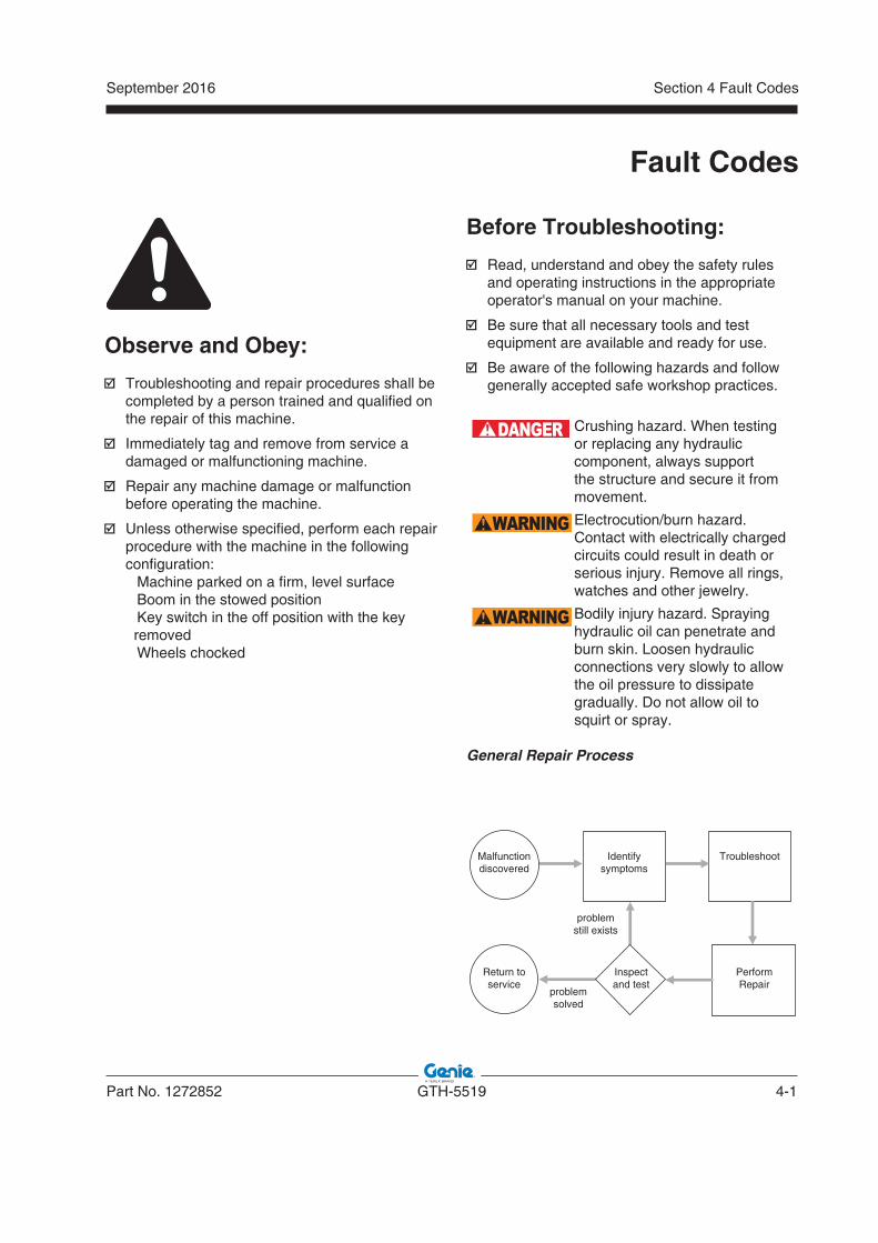
September 2016
Part No. 1272852 GTH-5519 4-1
Section 4 Fault Codes
Fault Codes
Observe and Obey:
Troubleshooting and repair procedures shall be completed by a person trained and qualified on the repair of this machine.
Immediately tag and remove from service a damaged or malfunctioning machine.
Repair any machine damage or malfunction before operating the machine.
Unless otherwise specified, perform each repair procedure with the machine in the following configuration:
� Machine parked on a firm, level surface � Boom in the stowed position � Key switch in the off position with the key removed � Wheels chocked
Before Troubleshooting:
Read, understand and obey the safety rules and operating instructions in the appropriate operator's manual on your machine.
Be sure that all necessary tools and test equipment are available and ready for use.
Be aware of the following hazards and follow generally accepted safe workshop practices.
DANGER Crushing hazard. When testing or replacing any hydraulic component, always support the structure and secure it from movement.
WARNING Electrocution/burn hazard. Contact with electrically charged circuits could result in death or serious injury. Remove all rings, watches and other jewelry.
WARNING Bodily injury hazard. Spraying hydraulic oil can penetrate and burn skin. Loosen hydraulic connections very slowly to allow the oil pressure to dissipate gradually. Do not allow oil to squirt or spray.
General Repair Process
Malfunctiondiscovered
Identifysymptoms
Troubleshoot
PerformRepair
Inspectand test
Return toservice
problemstill exists
problemsolved
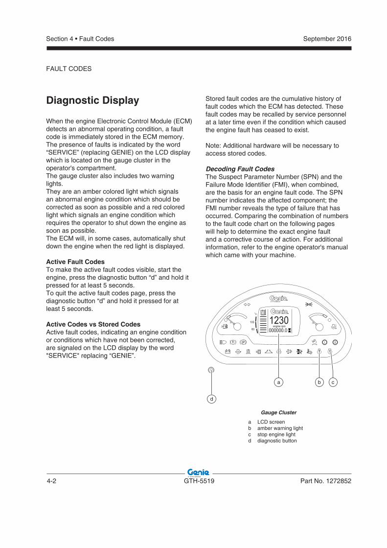
4-2 GTH-5519 Part No. 1272852
September 2016Section 4 • Fault Codes
Diagnostic Display
When the engine Electronic Control Module (ECM) detects an abnormal operating condition, a fault code is immediately stored in the ECM memory.The presence of faults is indicated by the word “SERVICE” (replacing GENIE) on the LCD display which is located on the gauge cluster in the operator's compartment.The gauge cluster also includes two warning lights.They are an amber colored light which signals an abnormal engine condition which should be corrected as soon as possible and a red colored light which signals an engine condition which requires the operator to shut down the engine as soon as possible.The ECM will, in some cases, automatically shut down the engine when the red light is displayed.
Active Fault CodesTo make the active fault codes visible, start the engine, press the diagnostic button “d” and hold it pressed for at least 5 seconds.To quit the active fault codes page, press the diagnostic button “d” and hold it pressed for at least 5 seconds.
Active Codes vs Stored CodesActive fault codes, indicating an engine condition or conditions which have not been corrected, are signaled on the LCD display by the word "SERVICE" replacing “GENIE”.
Stored fault codes are the cumulative history of fault codes which the ECM has detected. These fault codes may be recalled by service personnel at a later time even if the condition which caused the engine fault has ceased to exist.
Note: Additional hardware will be necessary to access stored codes.
Decoding Fault CodesThe Suspect Parameter Number (SPN) and the Failure Mode Identifier (FMI), when combined, are the basis for an engine fault code. The SPN number indicates the affected component; the FMI number reveals the type of failure that has occurred. Comparing the combination of numbers to the fault code chart on the following pages will help to determine the exact engine fault and a corrective course of action. For additional information, refer to the engine operator's manual which came with your machine.
FAULT CODES
engine rpm000000.01230
°c
105
60
Gauge Cluster
a LCD screenb amber warning lightc stop engine lightd diagnostic button
d
a b c
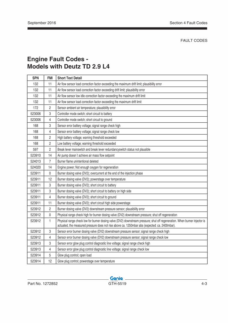
September 2016
Part No. 1272852 GTH-5519 4-3
Section 4 Fault Codes
Engine Fault Codes -Models with Deutz TD 2.9 L4
SPN FMI Short Text Detail
132 11 Air flow sensor load correction factor exceeding the maximum drift limit; plausibility error
132 11 Air flow sensor load correction factor exceeding drift limit; plausibility error
132 11 Air flow sensor low idle correction factor exceeding the maximum drift limit
132 11 Air flow sensor load correction factor exceeding the maximum drift limit
172 2 Sensor ambient air temperature; plausibility error
523006 3 Controller mode switch; short circuit to battery
523006 4 Controller mode switch; short circuit to ground
168 3 Sensor error battery voltage; signal range check high
168 4 Sensor error battery voltage; signal range check low
168 2 High battery voltage; warning threshold exceeded
168 2 Low battery voltage; warning threshold exceeded
597 2 Break lever mainswitch and break lever redundancyswitch status not plausible
523910 14 Air pump doesn´t achieve air mass flow setpoint
524013 7 Burner flame unintentional deleted
524020 14 Engine power; Not enough oxygen for regeneration
523911 0 Burner dosing valve (DV2); overcurrent at the end of the injection phase
523911 12 Burner dosing valve (DV2); powerstage over temperature
523911 3 Burner dosing valve (DV2); short circuit to battery
523911 3 Burner dosing valve (DV2); short circuit to battery on high side
523911 4 Burner dosing valve (DV2); short circuit to ground
523911 11 Burner dosing valve (DV2); short circuit high side powerstage
523912 2 Burner dosing valve (DV2) downstream pressure sensor; plausibility error
523912 0 Physical range check high for burner dosing valve (DV2) downstream pressure; shut off regeneration
523912 1 Physical range check low for burner dosing valve (DV2) downstream pressure; shut off regeneration. When burner injector is actuated, the measured pressure does not rise above ca. 1250mbar abs (expected: ca. 2400mbar).
523912 3 Sensor error burner dosing valve (DV2) downstream pressure sensor; signal range check high
523912 4 Sensor error burner dosing valve (DV2) downstream pressure sensor; signal range check low
523913 3 Sensor error glow plug control diagnostic line voltage; signal range check high
523913 4 Sensor error glow plug control diagnostic line voltage; signal range check low
523914 5 Glow plug control; open load
523914 12 Glow plug control; powerstage over temperature
FAULT CODES
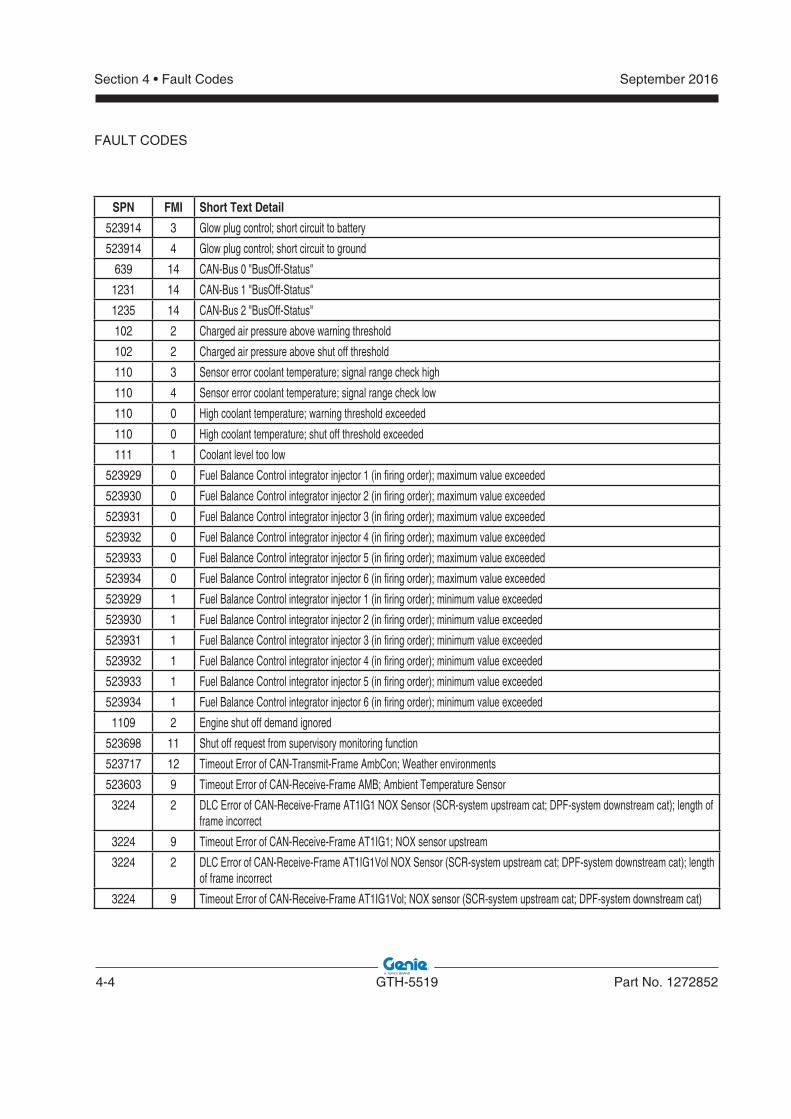
4-4 GTH-5519 Part No. 1272852
September 2016Section 4 • Fault Codes
FAULT CODES
SPN FMI Short Text Detail
523914 3 Glow plug control; short circuit to battery
523914 4 Glow plug control; short circuit to ground
639 14 CAN-Bus 0 "BusOff-Status"
1231 14 CAN-Bus 1 "BusOff-Status"
1235 14 CAN-Bus 2 "BusOff-Status"
102 2 Charged air pressure above warning threshold
102 2 Charged air pressure above shut off threshold
110 3 Sensor error coolant temperature; signal range check high
110 4 Sensor error coolant temperature; signal range check low
110 0 High coolant temperature; warning threshold exceeded
110 0 High coolant temperature; shut off threshold exceeded
111 1 Coolant level too low
523929 0 Fuel Balance Control integrator injector 1 (in firing order); maximum value exceeded
523930 0 Fuel Balance Control integrator injector 2 (in firing order); maximum value exceeded
523931 0 Fuel Balance Control integrator injector 3 (in firing order); maximum value exceeded
523932 0 Fuel Balance Control integrator injector 4 (in firing order); maximum value exceeded
523933 0 Fuel Balance Control integrator injector 5 (in firing order); maximum value exceeded
523934 0 Fuel Balance Control integrator injector 6 (in firing order); maximum value exceeded
523929 1 Fuel Balance Control integrator injector 1 (in firing order); minimum value exceeded
523930 1 Fuel Balance Control integrator injector 2 (in firing order); minimum value exceeded
523931 1 Fuel Balance Control integrator injector 3 (in firing order); minimum value exceeded
523932 1 Fuel Balance Control integrator injector 4 (in firing order); minimum value exceeded
523933 1 Fuel Balance Control integrator injector 5 (in firing order); minimum value exceeded
523934 1 Fuel Balance Control integrator injector 6 (in firing order); minimum value exceeded
1109 2 Engine shut off demand ignored
523698 11 Shut off request from supervisory monitoring function
523717 12 Timeout Error of CAN-Transmit-Frame AmbCon; Weather environments
523603 9 Timeout Error of CAN-Receive-Frame AMB; Ambient Temperature Sensor
3224 2 DLC Error of CAN-Receive-Frame AT1IG1 NOX Sensor (SCR-system upstream cat; DPF-system downstream cat); length of frame incorrect
3224 9 Timeout Error of CAN-Receive-Frame AT1IG1; NOX sensor upstream
3224 2 DLC Error of CAN-Receive-Frame AT1IG1Vol NOX Sensor (SCR-system upstream cat; DPF-system downstream cat); length of frame incorrect
3224 9 Timeout Error of CAN-Receive-Frame AT1IG1Vol; NOX sensor (SCR-system upstream cat; DPF-system downstream cat)
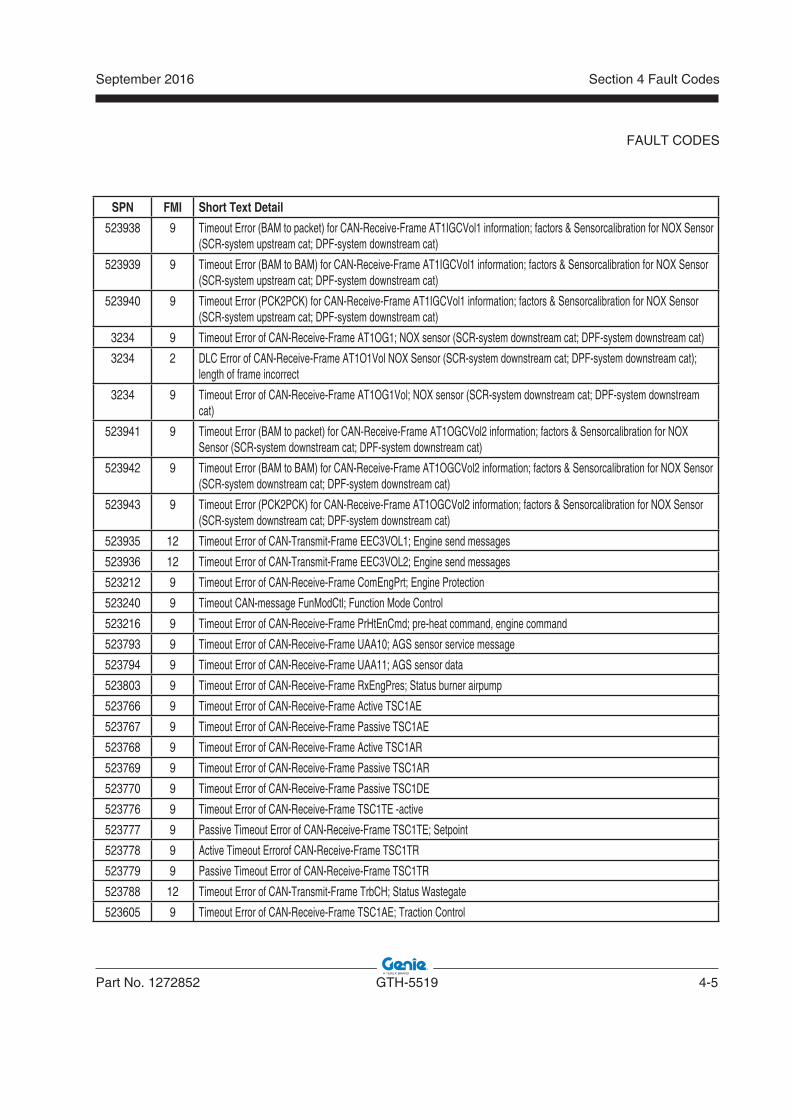
September 2016
Part No. 1272852 GTH-5519 4-5
Section 4 Fault Codes
FAULT CODES
SPN FMI Short Text Detail
523938 9 Timeout Error (BAM to packet) for CAN-Receive-Frame AT1IGCVol1 information; factors & Sensorcalibration for NOX Sensor (SCR-system upstream cat; DPF-system downstream cat)
523939 9 Timeout Error (BAM to BAM) for CAN-Receive-Frame AT1IGCVol1 information; factors & Sensorcalibration for NOX Sensor (SCR-system upstream cat; DPF-system downstream cat)
523940 9 Timeout Error (PCK2PCK) for CAN-Receive-Frame AT1IGCVol1 information; factors & Sensorcalibration for NOX Sensor (SCR-system upstream cat; DPF-system downstream cat)
3234 9 Timeout Error of CAN-Receive-Frame AT1OG1; NOX sensor (SCR-system downstream cat; DPF-system downstream cat)
3234 2 DLC Error of CAN-Receive-Frame AT1O1Vol NOX Sensor (SCR-system downstream cat; DPF-system downstream cat); length of frame incorrect
3234 9 Timeout Error of CAN-Receive-Frame AT1OG1Vol; NOX sensor (SCR-system downstream cat; DPF-system downstream cat)
523941 9 Timeout Error (BAM to packet) for CAN-Receive-Frame AT1OGCVol2 information; factors & Sensorcalibration for NOX Sensor (SCR-system downstream cat; DPF-system downstream cat)
523942 9 Timeout Error (BAM to BAM) for CAN-Receive-Frame AT1OGCVol2 information; factors & Sensorcalibration for NOX Sensor (SCR-system downstream cat; DPF-system downstream cat)
523943 9 Timeout Error (PCK2PCK) for CAN-Receive-Frame AT1OGCVol2 information; factors & Sensorcalibration for NOX Sensor (SCR-system downstream cat; DPF-system downstream cat)
523935 12 Timeout Error of CAN-Transmit-Frame EEC3VOL1; Engine send messages
523936 12 Timeout Error of CAN-Transmit-Frame EEC3VOL2; Engine send messages
523212 9 Timeout Error of CAN-Receive-Frame ComEngPrt; Engine Protection
523240 9 Timeout CAN-message FunModCtl; Function Mode Control
523216 9 Timeout Error of CAN-Receive-Frame PrHtEnCmd; pre-heat command, engine command
523793 9 Timeout Error of CAN-Receive-Frame UAA10; AGS sensor service message
523794 9 Timeout Error of CAN-Receive-Frame UAA11; AGS sensor data
523803 9 Timeout Error of CAN-Receive-Frame RxEngPres; Status burner airpump
523766 9 Timeout Error of CAN-Receive-Frame Active TSC1AE
523767 9 Timeout Error of CAN-Receive-Frame Passive TSC1AE
523768 9 Timeout Error of CAN-Receive-Frame Active TSC1AR
523769 9 Timeout Error of CAN-Receive-Frame Passive TSC1AR
523770 9 Timeout Error of CAN-Receive-Frame Passive TSC1DE
523776 9 Timeout Error of CAN-Receive-Frame TSC1TE -active
523777 9 Passive Timeout Error of CAN-Receive-Frame TSC1TE; Setpoint
523778 9 Active Timeout Errorof CAN-Receive-Frame TSC1TR
523779 9 Passive Timeout Error of CAN-Receive-Frame TSC1TR
523788 12 Timeout Error of CAN-Transmit-Frame TrbCH; Status Wastegate
523605 9 Timeout Error of CAN-Receive-Frame TSC1AE; Traction Control
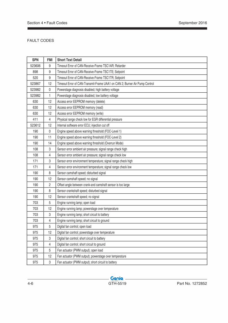
4-6 GTH-5519 Part No. 1272852
September 2016Section 4 • Fault Codes
FAULT CODES
SPN FMI Short Text Detail
523606 9 Timeout Error of CAN-Receive-Frame TSC1AR; Retarder
898 9 Timeout Error of CAN-Receive-Frame TSC1TE; Setpoint
520 9 Timeout Error of CAN-Receive-Frame TSC1TR; Setpoint
523867 12 Timeout Error of CAN-Transmit-Frame UAA1 on CAN 2; Burner Air Pump Control
523982 0 Powerstage diagnosis disabled; high battery voltage
523982 1 Powerstage diagnosis disabled; low battery voltage
630 12 Access error EEPROM memory (delete)
630 12 Access error EEPROM memory (read)
630 12 Access error EEPROM memory (write)
411 4 Physical range check low for EGR differential pressure
523612 12 Internal software error ECU; injection cut off
190 0 Engine speed above warning threshold (FOC-Level 1)
190 11 Engine speed above warning threshold (FOC-Level 2)
190 14 Engine speed above warning threshold (Overrun Mode)
108 3 Sensor error ambient air pressure; signal range check high
108 4 Sensor error ambient air pressure; signal range check low
171 3 Sensor error environment temperature; signal range check high
171 4 Sensor error environment temperature; signal range check low
190 8 Sensor camshaft speed; disturbed signal
190 12 Sensor camshaft speed; no signal
190 2 Offset angle between crank-and camshaft sensor is too large
190 8 Sensor crankshaft speed; disturbed signal
190 12 Sensor crankshaft speed; no signal
703 5 Engine running lamp; open load
703 12 Engine running lamp; powerstage over temperature
703 3 Engine running lamp; short circuit to battery
703 4 Engine running lamp; short circuit to ground
975 5 Digital fan control; open load
975 12 Digital fan control; powerstage over temperature
975 3 Digital fan control; short circuit to battery
975 4 Digital fan control; short circuit to ground
975 5 Fan actuator (PWM output); open load
975 12 Fan actuator (PWM output); powerstage over temperature
975 3 Fan actuator (PWM output); short circuit to battery
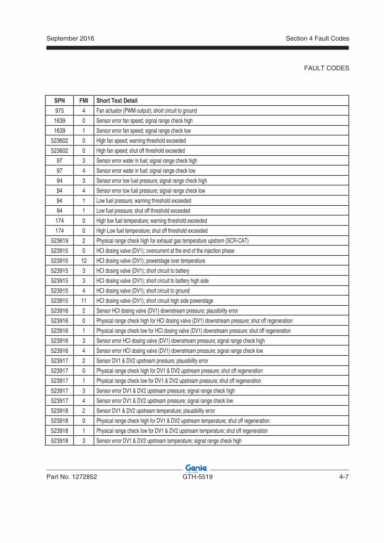
September 2016
Part No. 1272852 GTH-5519 4-7
Section 4 Fault Codes
FAULT CODES
SPN FMI Short Text Detail
975 4 Fan actuator (PWM output); short circuit to ground
1639 0 Sensor error fan speed; signal range check high
1639 1 Sensor error fan speed; signal range check low
523602 0 High fan speed; warning threshold exceeded
523602 0 High fan speed; shut off threshold exceeded
97 3 Sensor error water in fuel; signal range check high
97 4 Sensor error water in fuel; signal range check low
94 3 Sensor error low fuel pressure; signal range check high
94 4 Sensor error low fuel pressure; signal range check low
94 1 Low fuel pressure; warning threshold exceeded
94 1 Low fuel pressure; shut off threshold exceeded
174 0 High low fuel temperature; warning threshold exceeded
174 0 High Low fuel temperature; shut off threshold exceeded
523619 2 Physical range check high for exhaust gas temperature upstrem (SCR-CAT)
523915 0 HCI dosing valve (DV1); overcurrent at the end of the injection phase
523915 12 HCI dosing valve (DV1); powerstage over temperature
523915 3 HCI dosing valve (DV1); short circuit to battery
523915 3 HCI dosing valve (DV1); short circuit to battery high side
523915 4 HCI dosing valve (DV1); short circuit to ground
523915 11 HCI dosing valve (DV1); short circuit high side powerstage
523916 2 Sensor HCI dosing valve (DV1) downstream pressure; plausibility error
523916 0 Physical range check high for HCI dosing valve (DV1) downstream pressure; shut off regeneration
523916 1 Physical range check low for HCI dosing valve (DV1) downstream pressure; shut off regeneration
523916 3 Sensor error HCI dosing valve (DV1) downstream pressure; signal range check high
523916 4 Sensor error HCI dosing valve (DV1) downstream pressure; signal range check low
523917 2 Sensor DV1 & DV2 upstream pressure; plausibility error
523917 0 Physical range check high for DV1 & DV2 upstream pressure; shut off regeneration
523917 1 Physical range check low for DV1 & DV2 upstream pressure; shut off regeneration
523917 3 Sensor error DV1 & DV2 upstream pressure; signal range check high
523917 4 Sensor error DV1 & DV2 upstream pressure; signal range check low
523918 2 Sensor DV1 & DV2 upstream temperature; plausibility error
523918 0 Physical range check high for DV1 & DV2 upstream temperature; shut off regeneration
523918 1 Physical range check low for DV1 & DV2 upstream temperature; shut off regeneration
523918 3 Sensor error DV1 & DV2 upstream temperature; signal range check high
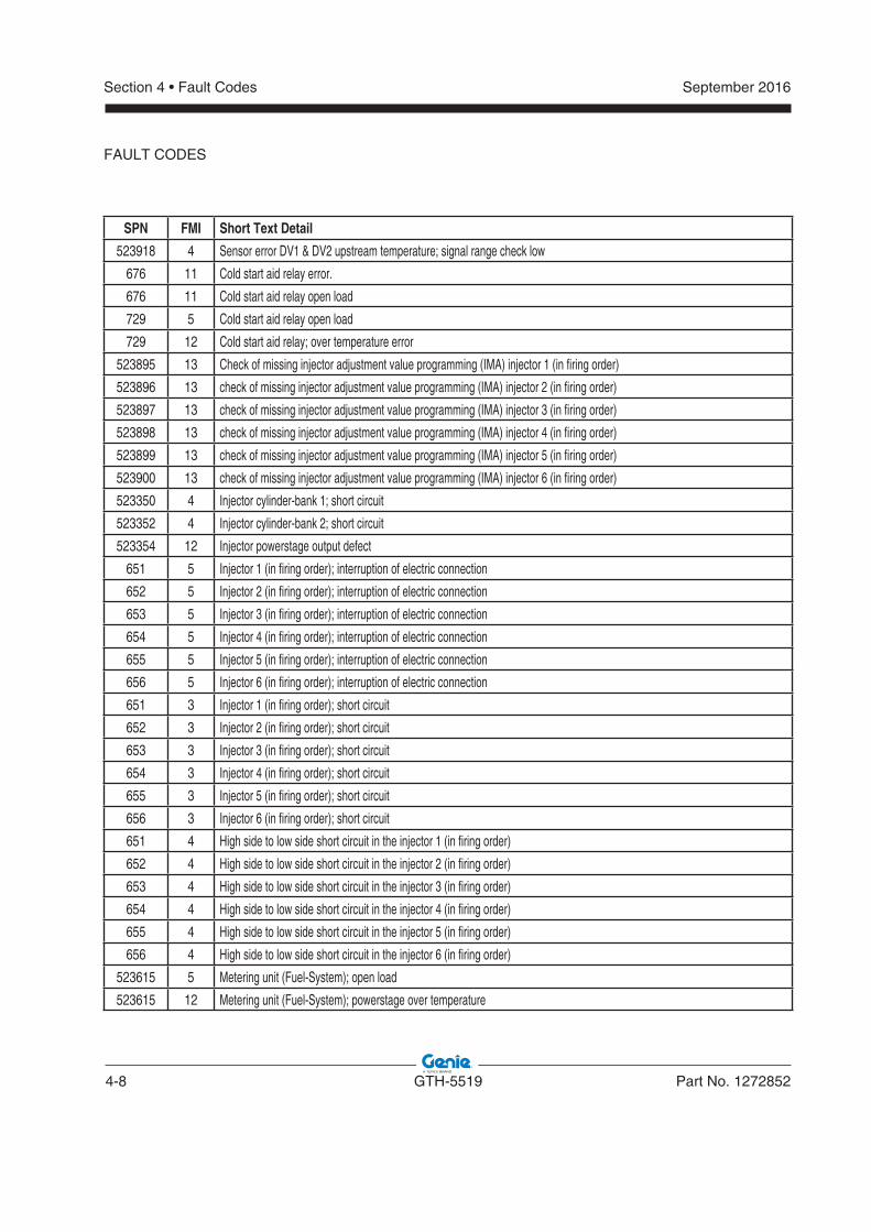
4-8 GTH-5519 Part No. 1272852
September 2016Section 4 • Fault Codes
FAULT CODES
SPN FMI Short Text Detail
523918 4 Sensor error DV1 & DV2 upstream temperature; signal range check low
676 11 Cold start aid relay error.
676 11 Cold start aid relay open load
729 5 Cold start aid relay open load
729 12 Cold start aid relay; over temperature error
523895 13 Check of missing injector adjustment value programming (IMA) injector 1 (in firing order)
523896 13 check of missing injector adjustment value programming (IMA) injector 2 (in firing order)
523897 13 check of missing injector adjustment value programming (IMA) injector 3 (in firing order)
523898 13 check of missing injector adjustment value programming (IMA) injector 4 (in firing order)
523899 13 check of missing injector adjustment value programming (IMA) injector 5 (in firing order)
523900 13 check of missing injector adjustment value programming (IMA) injector 6 (in firing order)
523350 4 Injector cylinder-bank 1; short circuit
523352 4 Injector cylinder-bank 2; short circuit
523354 12 Injector powerstage output defect
651 5 Injector 1 (in firing order); interruption of electric connection
652 5 Injector 2 (in firing order); interruption of electric connection
653 5 Injector 3 (in firing order); interruption of electric connection
654 5 Injector 4 (in firing order); interruption of electric connection
655 5 Injector 5 (in firing order); interruption of electric connection
656 5 Injector 6 (in firing order); interruption of electric connection
651 3 Injector 1 (in firing order); short circuit
652 3 Injector 2 (in firing order); short circuit
653 3 Injector 3 (in firing order); short circuit
654 3 Injector 4 (in firing order); short circuit
655 3 Injector 5 (in firing order); short circuit
656 3 Injector 6 (in firing order); short circuit
651 4 High side to low side short circuit in the injector 1 (in firing order)
652 4 High side to low side short circuit in the injector 2 (in firing order)
653 4 High side to low side short circuit in the injector 3 (in firing order)
654 4 High side to low side short circuit in the injector 4 (in firing order)
655 4 High side to low side short circuit in the injector 5 (in firing order)
656 4 High side to low side short circuit in the injector 6 (in firing order)
523615 5 Metering unit (Fuel-System); open load
523615 12 Metering unit (Fuel-System); powerstage over temperature
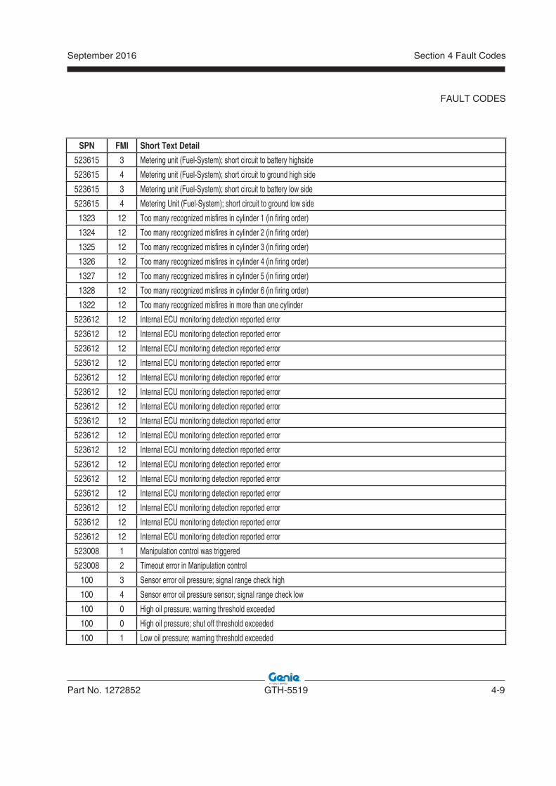
September 2016
Part No. 1272852 GTH-5519 4-9
Section 4 Fault Codes
FAULT CODES
SPN FMI Short Text Detail
523615 3 Metering unit (Fuel-System); short circuit to battery highside
523615 4 Metering unit (Fuel-System); short circuit to ground high side
523615 3 Metering unit (Fuel-System); short circuit to battery low side
523615 4 Metering Unit (Fuel-System); short circuit to ground low side
1323 12 Too many recognized misfires in cylinder 1 (in firing order)
1324 12 Too many recognized misfires in cylinder 2 (in firing order)
1325 12 Too many recognized misfires in cylinder 3 (in firing order)
1326 12 Too many recognized misfires in cylinder 4 (in firing order)
1327 12 Too many recognized misfires in cylinder 5 (in firing order)
1328 12 Too many recognized misfires in cylinder 6 (in firing order)
1322 12 Too many recognized misfires in more than one cylinder
523612 12 Internal ECU monitoring detection reported error
523612 12 Internal ECU monitoring detection reported error
523612 12 Internal ECU monitoring detection reported error
523612 12 Internal ECU monitoring detection reported error
523612 12 Internal ECU monitoring detection reported error
523612 12 Internal ECU monitoring detection reported error
523612 12 Internal ECU monitoring detection reported error
523612 12 Internal ECU monitoring detection reported error
523612 12 Internal ECU monitoring detection reported error
523612 12 Internal ECU monitoring detection reported error
523612 12 Internal ECU monitoring detection reported error
523612 12 Internal ECU monitoring detection reported error
523612 12 Internal ECU monitoring detection reported error
523612 12 Internal ECU monitoring detection reported error
523612 12 Internal ECU monitoring detection reported error
523612 12 Internal ECU monitoring detection reported error
523008 1 Manipulation control was triggered
523008 2 Timeout error in Manipulation control
100 3 Sensor error oil pressure; signal range check high
100 4 Sensor error oil pressure sensor; signal range check low
100 0 High oil pressure; warning threshold exceeded
100 0 High oil pressure; shut off threshold exceeded
100 1 Low oil pressure; warning threshold exceeded
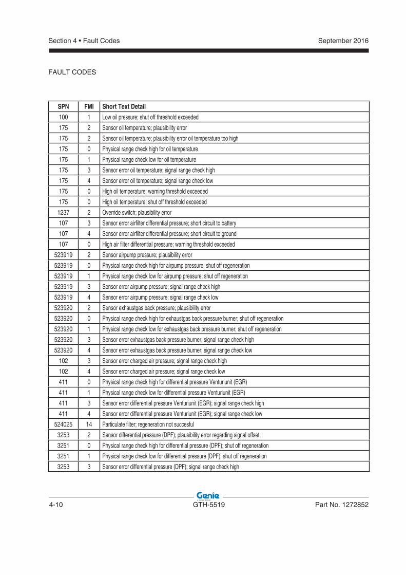
4-10 GTH-5519 Part No. 1272852
September 2016Section 4 • Fault Codes
FAULT CODES
SPN FMI Short Text Detail
100 1 Low oil pressure; shut off threshold exceeded
175 2 Sensor oil temperature; plausibility error
175 2 Sensor oil temperature; plausibility error oil temperature too high
175 0 Physical range check high for oil temperature
175 1 Physical range check low for oil temperature
175 3 Sensor error oil temperature; signal range check high
175 4 Sensor error oil temperature; signal range check low
175 0 High oil temperature; warning threshold exceeded
175 0 High oil temperature; shut off threshold exceeded
1237 2 Override switch; plausibility error
107 3 Sensor error airfilter differential pressure; short circuit to battery
107 4 Sensor error airfilter differential pressure; short circuit to ground
107 0 High air filter differential pressure; warning threshold exceeded
523919 2 Sensor airpump pressure; plausibility error
523919 0 Physical range check high for airpump pressure; shut off regeneration
523919 1 Physical range check low for airpump pressure; shut off regeneration
523919 3 Sensor error airpump pressure; signal range check high
523919 4 Sensor error airpump pressure; signal range check low
523920 2 Sensor exhaustgas back pressure; plausibility error
523920 0 Physical range check high for exhaustgas back pressure burner; shut off regeneration
523920 1 Physical range check low for exhaustgas back pressure burner; shut off regeneration
523920 3 Sensor error exhaustgas back pressure burner; signal range check high
523920 4 Sensor error exhaustgas back pressure burner; signal range check low
102 3 Sensor error charged air pressure; signal range check high
102 4 Sensor error charged air pressure; signal range check low
411 0 Physical range check high for differential pressure Venturiunit (EGR)
411 1 Physical range check low for differential pressure Venturiunit (EGR)
411 3 Sensor error differential pressure Venturiunit (EGR); signal range check high
411 4 Sensor error differential pressure Venturiunit (EGR); signal range check low
524025 14 Particulate filter; regeneration not succesful
3253 2 Sensor differential pressure (DPF); plausibility error regarding signal offset
3251 0 Physical range check high for differential pressure (DPF); shut off regeneration
3251 1 Physical range check low for differential pressure (DPF); shut off regeneration
3253 3 Sensor error differential pressure (DPF); signal range check high
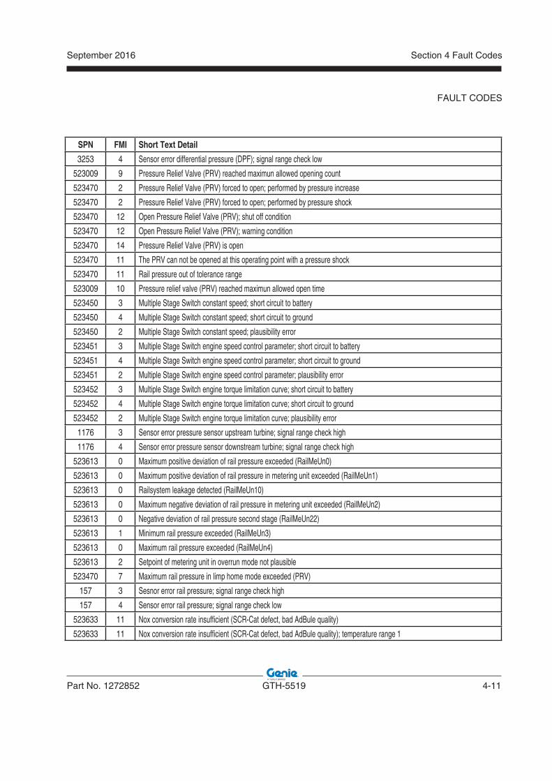
September 2016
Part No. 1272852 GTH-5519 4-11
Section 4 Fault Codes
FAULT CODES
SPN FMI Short Text Detail
3253 4 Sensor error differential pressure (DPF); signal range check low
523009 9 Pressure Relief Valve (PRV) reached maximun allowed opening count
523470 2 Pressure Relief Valve (PRV) forced to open; performed by pressure increase
523470 2 Pressure Relief Valve (PRV) forced to open; performed by pressure shock
523470 12 Open Pressure Relief Valve (PRV); shut off condition
523470 12 Open Pressure Relief Valve (PRV); warning condition
523470 14 Pressure Relief Valve (PRV) is open
523470 11 The PRV can not be opened at this operating point with a pressure shock
523470 11 Rail pressure out of tolerance range
523009 10 Pressure relief valve (PRV) reached maximun allowed open time
523450 3 Multiple Stage Switch constant speed; short circuit to battery
523450 4 Multiple Stage Switch constant speed; short circuit to ground
523450 2 Multiple Stage Switch constant speed; plausibility error
523451 3 Multiple Stage Switch engine speed control parameter; short circuit to battery
523451 4 Multiple Stage Switch engine speed control parameter; short circuit to ground
523451 2 Multiple Stage Switch engine speed control parameter; plausibility error
523452 3 Multiple Stage Switch engine torque limitation curve; short circuit to battery
523452 4 Multiple Stage Switch engine torque limitation curve; short circuit to ground
523452 2 Multiple Stage Switch engine torque limitation curve; plausibility error
1176 3 Sensor error pressure sensor upstream turbine; signal range check high
1176 4 Sensor error pressure sensor downstream turbine; signal range check high
523613 0 Maximum positive deviation of rail pressure exceeded (RailMeUn0)
523613 0 Maximum positive deviation of rail pressure in metering unit exceeded (RailMeUn1)
523613 0 Railsystem leakage detected (RailMeUn10)
523613 0 Maximum negative deviation of rail pressure in metering unit exceeded (RailMeUn2)
523613 0 Negative deviation of rail pressure second stage (RailMeUn22)
523613 1 Minimum rail pressure exceeded (RailMeUn3)
523613 0 Maximum rail pressure exceeded (RailMeUn4)
523613 2 Setpoint of metering unit in overrun mode not plausible
523470 7 Maximum rail pressure in limp home mode exceeded (PRV)
157 3 Sesnor error rail pressure; signal range check high
157 4 Sensor error rail pressure; signal range check low
523633 11 Nox conversion rate insufficient (SCR-Cat defect, bad AdBule quality)
523633 11 Nox conversion rate insufficient (SCR-Cat defect, bad AdBule quality); temperature range 1
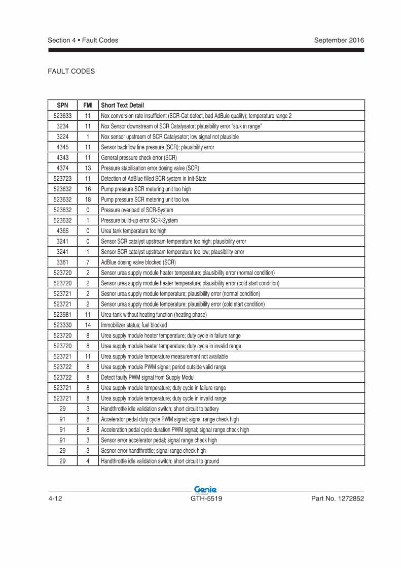
4-12 GTH-5519 Part No. 1272852
September 2016Section 4 • Fault Codes
SPN FMI Short Text Detail
523633 11 Nox conversion rate insufficient (SCR-Cat defect, bad AdBule quality); temperature range 2
3234 11 Nox Sensor downstream of SCR Catalysator; plausibility error "stuk in range"
3224 1 Nox sensor upstream of SCR Catalysator; low signal not plausible
4345 11 Sensor backflow line pressure (SCR); plausibility error
4343 11 General pressure check error (SCR)
4374 13 Pressure stabilisation error dosing valve (SCR)
523723 11 Detection of AdBlue filled SCR system in Init-State
523632 16 Pump pressure SCR metering unit too high
523632 18 Pump pressure SCR metering unit too low
523632 0 Pressure overload of SCR-System
523632 1 Pressure build-up error SCR-System
4365 0 Urea tank temperature too high
3241 0 Sensor SCR catalyst upstream temperature too high; plausibility error
3241 1 Sensor SCR catalyst upstream temperature too low; plausibility error
3361 7 AdBlue dosing valve blocked (SCR)
523720 2 Sensor urea supply module heater temperature; plausibility error (normal condition)
523720 2 Sensor urea supply module heater temperature; plausibility error (cold start condition)
523721 2 Sesnor urea supply module temperature; plausibility error (normal condition)
523721 2 Sensor urea supply module temperature; plausibility error (cold start condition)
523981 11 Urea-tank without heating function (heating phase)
523330 14 Immobilizer status; fuel blocked
523720 8 Urea supply module heater temperature; duty cycle in failure range
523720 8 Urea supply module heater temperature; duty cycle in invalid range
523721 11 Urea supply module temperature measurement not available
523722 8 Urea supply module PWM signal; period outside valid range
523722 8 Detect faulty PWM signal from Supply Modul
523721 8 Urea supply module temperature; duty cycle in failure range
523721 8 Urea supply module temperature; duty cycle in invalid range
29 3 Handthrottle idle validation switch; short circuit to battery
91 8 Accelerator pedal duty cycle PWM signal; signal range check high
91 8 Acceleration pedal cycle duration PWM signal; signal range check high
91 3 Sensor error accelerator pedal; signal range check high
29 3 Sesnor error handthrottle; signal range check high
29 4 Handthrottle idle validation switch; short circuit to ground
FAULT CODES
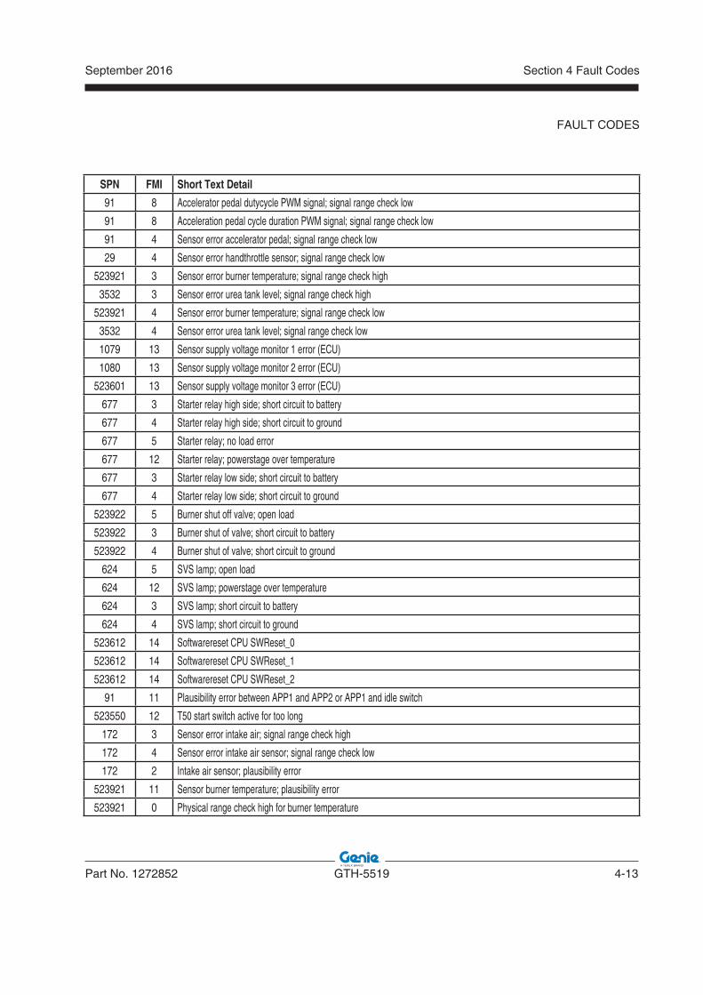
September 2016
Part No. 1272852 GTH-5519 4-13
Section 4 Fault Codes
SPN FMI Short Text Detail
91 8 Accelerator pedal dutycycle PWM signal; signal range check low
91 8 Acceleration pedal cycle duration PWM signal; signal range check low
91 4 Sensor error accelerator pedal; signal range check low
29 4 Sensor error handthrottle sensor; signal range check low
523921 3 Sensor error burner temperature; signal range check high
3532 3 Sensor error urea tank level; signal range check high
523921 4 Sensor error burner temperature; signal range check low
3532 4 Sensor error urea tank level; signal range check low
1079 13 Sensor supply voltage monitor 1 error (ECU)
1080 13 Sensor supply voltage monitor 2 error (ECU)
523601 13 Sensor supply voltage monitor 3 error (ECU)
677 3 Starter relay high side; short circuit to battery
677 4 Starter relay high side; short circuit to ground
677 5 Starter relay; no load error
677 12 Starter relay; powerstage over temperature
677 3 Starter relay low side; short circuit to battery
677 4 Starter relay low side; short circuit to ground
523922 5 Burner shut off valve; open load
523922 3 Burner shut of valve; short circuit to battery
523922 4 Burner shut of valve; short circuit to ground
624 5 SVS lamp; open load
624 12 SVS lamp; powerstage over temperature
624 3 SVS lamp; short circuit to battery
624 4 SVS lamp; short circuit to ground
523612 14 Softwarereset CPU SWReset_0
523612 14 Softwarereset CPU SWReset_1
523612 14 Softwarereset CPU SWReset_2
91 11 Plausibility error between APP1 and APP2 or APP1 and idle switch
523550 12 T50 start switch active for too long
172 3 Sensor error intake air; signal range check high
172 4 Sensor error intake air sensor; signal range check low
172 2 Intake air sensor; plausibility error
523921 11 Sensor burner temperature; plausibility error
523921 0 Physical range check high for burner temperature
FAULT CODES
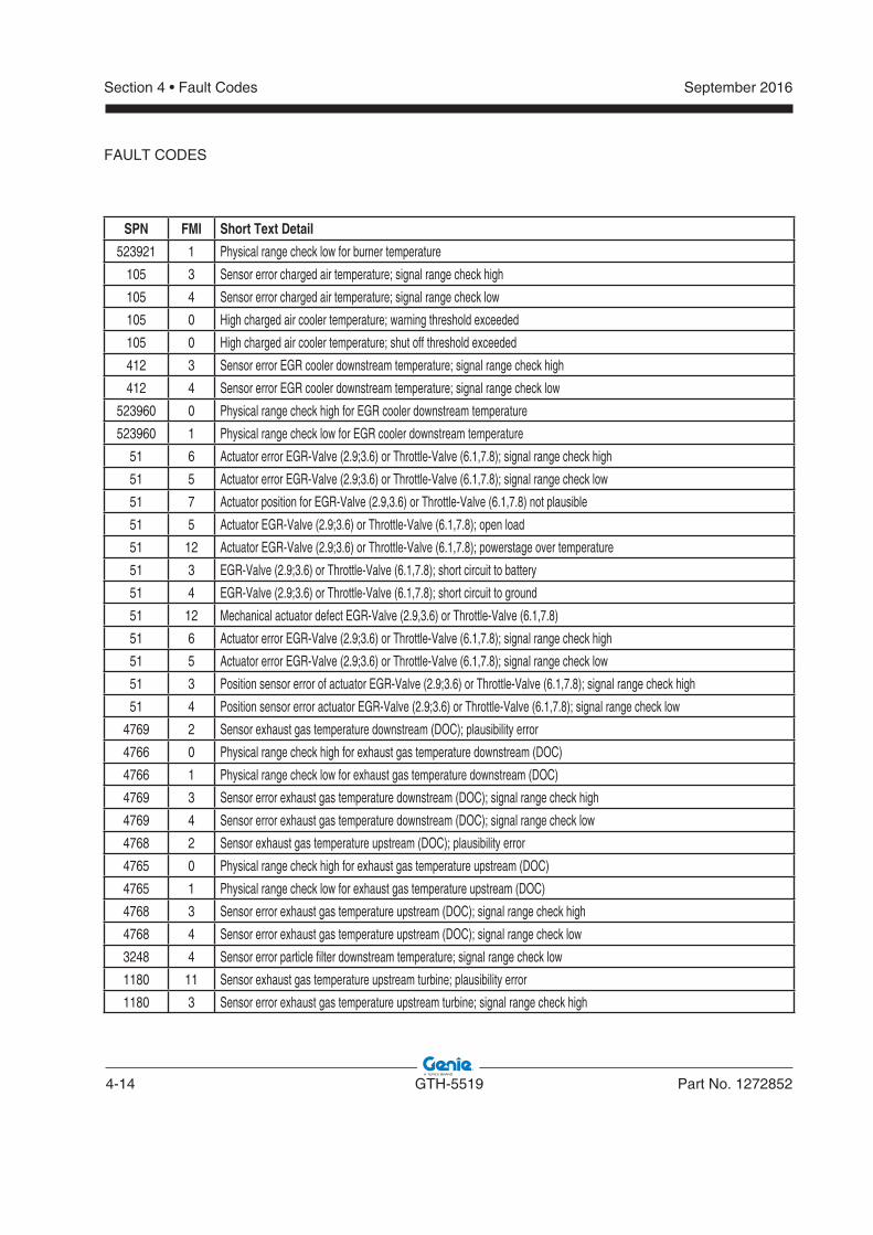
4-14 GTH-5519 Part No. 1272852
September 2016Section 4 • Fault Codes
SPN FMI Short Text Detail
523921 1 Physical range check low for burner temperature
105 3 Sensor error charged air temperature; signal range check high
105 4 Sensor error charged air temperature; signal range check low
105 0 High charged air cooler temperature; warning threshold exceeded
105 0 High charged air cooler temperature; shut off threshold exceeded
412 3 Sensor error EGR cooler downstream temperature; signal range check high
412 4 Sensor error EGR cooler downstream temperature; signal range check low
523960 0 Physical range check high for EGR cooler downstream temperature
523960 1 Physical range check low for EGR cooler downstream temperature
51 6 Actuator error EGR-Valve (2.9;3.6) or Throttle-Valve (6.1,7.8); signal range check high
51 5 Actuator error EGR-Valve (2.9;3.6) or Throttle-Valve (6.1,7.8); signal range check low
51 7 Actuator position for EGR-Valve (2.9,3.6) or Throttle-Valve (6.1,7.8) not plausible
51 5 Actuator EGR-Valve (2.9;3.6) or Throttle-Valve (6.1,7.8); open load
51 12 Actuator EGR-Valve (2.9;3.6) or Throttle-Valve (6.1,7.8); powerstage over temperature
51 3 EGR-Valve (2.9;3.6) or Throttle-Valve (6.1,7.8); short circuit to battery
51 4 EGR-Valve (2.9;3.6) or Throttle-Valve (6.1,7.8); short circuit to ground
51 12 Mechanical actuator defect EGR-Valve (2.9,3.6) or Throttle-Valve (6.1,7.8)
51 6 Actuator error EGR-Valve (2.9;3.6) or Throttle-Valve (6.1,7.8); signal range check high
51 5 Actuator error EGR-Valve (2.9;3.6) or Throttle-Valve (6.1,7.8); signal range check low
51 3 Position sensor error of actuator EGR-Valve (2.9;3.6) or Throttle-Valve (6.1,7.8); signal range check high
51 4 Position sensor error actuator EGR-Valve (2.9;3.6) or Throttle-Valve (6.1,7.8); signal range check low
4769 2 Sensor exhaust gas temperature downstream (DOC); plausibility error
4766 0 Physical range check high for exhaust gas temperature downstream (DOC)
4766 1 Physical range check low for exhaust gas temperature downstream (DOC)
4769 3 Sensor error exhaust gas temperature downstream (DOC); signal range check high
4769 4 Sensor error exhaust gas temperature downstream (DOC); signal range check low
4768 2 Sensor exhaust gas temperature upstream (DOC); plausibility error
4765 0 Physical range check high for exhaust gas temperature upstream (DOC)
4765 1 Physical range check low for exhaust gas temperature upstream (DOC)
4768 3 Sensor error exhaust gas temperature upstream (DOC); signal range check high
4768 4 Sensor error exhaust gas temperature upstream (DOC); signal range check low
3248 4 Sensor error particle filter downstream temperature; signal range check low
1180 11 Sensor exhaust gas temperature upstream turbine; plausibility error
1180 3 Sensor error exhaust gas temperature upstream turbine; signal range check high
FAULT CODES
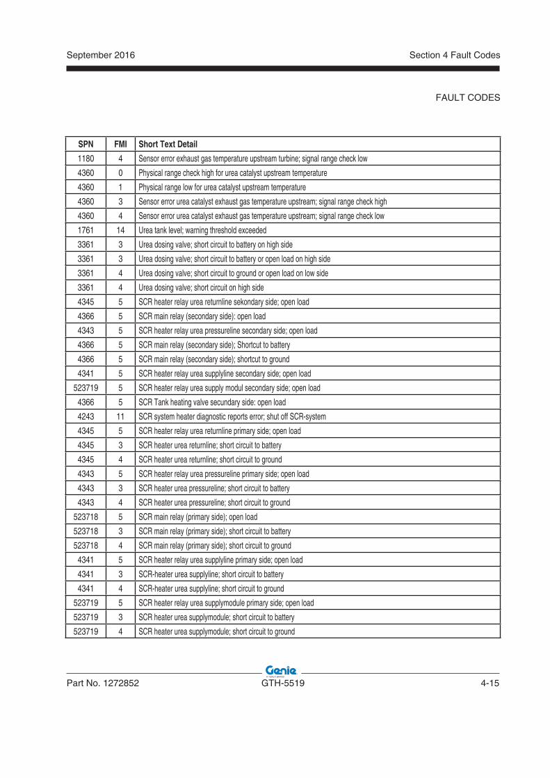
September 2016
Part No. 1272852 GTH-5519 4-15
Section 4 Fault Codes
SPN FMI Short Text Detail
1180 4 Sensor error exhaust gas temperature upstream turbine; signal range check low
4360 0 Physical range check high for urea catalyst upstream temperature
4360 1 Physical range low for urea catalyst upstream temperature
4360 3 Sensor error urea catalyst exhaust gas temperature upstream; signal range check high
4360 4 Sensor error urea catalyst exhaust gas temperature upstream; signal range check low
1761 14 Urea tank level; warning threshold exceeded
3361 3 Urea dosing valve; short circuit to battery on high side
3361 3 Urea dosing valve; short circuit to battery or open load on high side
3361 4 Urea dosing valve; short circuit to ground or open load on low side
3361 4 Urea dosing valve; short circuit on high side
4345 5 SCR heater relay urea returnline sekondary side; open load
4366 5 SCR main relay (secondary side): open load
4343 5 SCR heater relay urea pressureline secondary side; open load
4366 5 SCR main relay (secondary side); Shortcut to battery
4366 5 SCR main relay (secondary side); shortcut to ground
4341 5 SCR heater relay urea supplyline secondary side; open load
523719 5 SCR heater relay urea supply modul secondary side; open load
4366 5 SCR Tank heating valve secundary side: open load
4243 11 SCR system heater diagnostic reports error; shut off SCR-system
4345 5 SCR heater relay urea returnline primary side; open load
4345 3 SCR heater urea returnline; short circuit to battery
4345 4 SCR heater urea returnline; short circuit to ground
4343 5 SCR heater relay urea pressureline primary side; open load
4343 3 SCR heater urea pressureline; short circuit to battery
4343 4 SCR heater urea pressureline; short circuit to ground
523718 5 SCR main relay (primary side); open load
523718 3 SCR main relay (primary side); short circuit to battery
523718 4 SCR main relay (primary side); short circuit to ground
4341 5 SCR heater relay urea supplyline primary side; open load
4341 3 SCR-heater urea supplyline; short circuit to battery
4341 4 SCR-heater urea supplyline; short circuit to ground
523719 5 SCR heater relay urea supplymodule primary side; open load
523719 3 SCR heater urea supplymodule; short circuit to battery
523719 4 SCR heater urea supplymodule; short circuit to ground
FAULT CODES
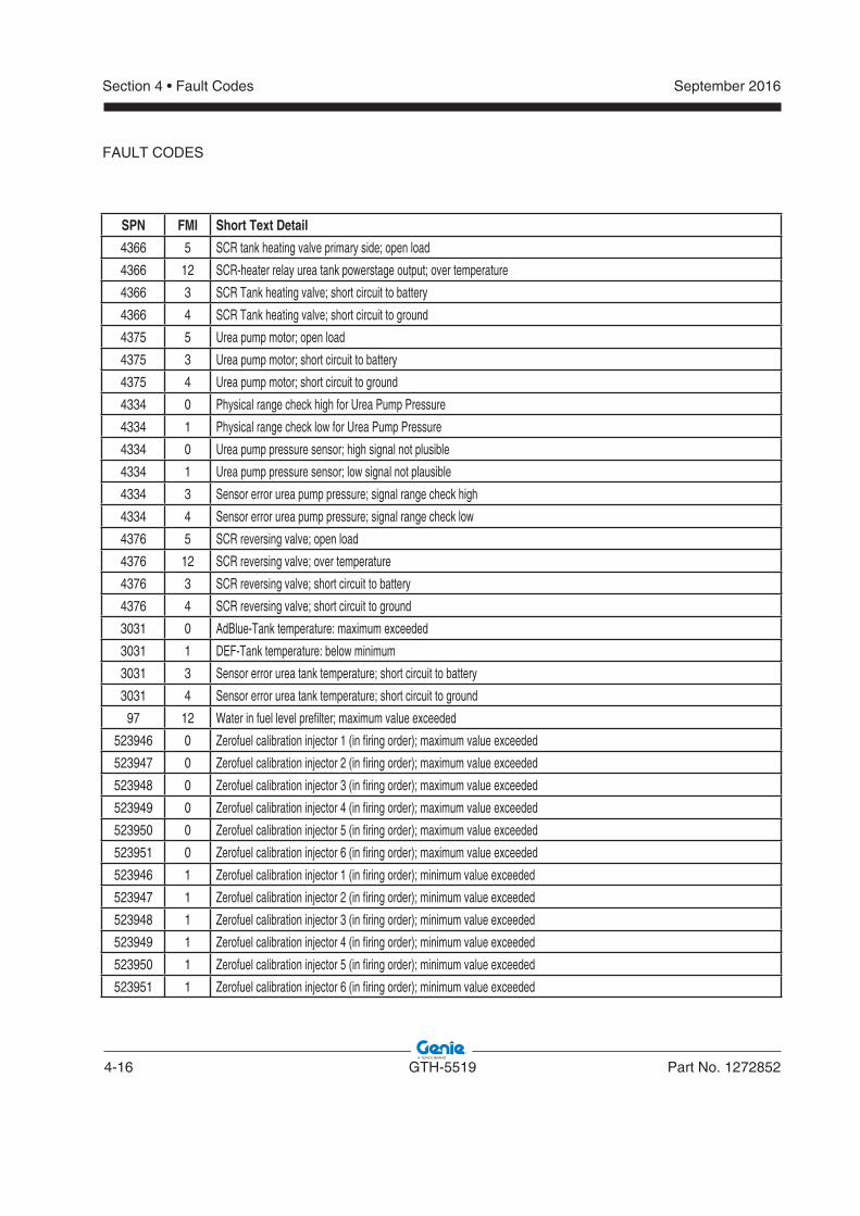
4-16 GTH-5519 Part No. 1272852
September 2016Section 4 • Fault Codes
SPN FMI Short Text Detail
4366 5 SCR tank heating valve primary side; open load
4366 12 SCR-heater relay urea tank powerstage output; over temperature
4366 3 SCR Tank heating valve; short circuit to battery
4366 4 SCR Tank heating valve; short circuit to ground
4375 5 Urea pump motor; open load
4375 3 Urea pump motor; short circuit to battery
4375 4 Urea pump motor; short circuit to ground
4334 0 Physical range check high for Urea Pump Pressure
4334 1 Physical range check low for Urea Pump Pressure
4334 0 Urea pump pressure sensor; high signal not plusible
4334 1 Urea pump pressure sensor; low signal not plausible
4334 3 Sensor error urea pump pressure; signal range check high
4334 4 Sensor error urea pump pressure; signal range check low
4376 5 SCR reversing valve; open load
4376 12 SCR reversing valve; over temperature
4376 3 SCR reversing valve; short circuit to battery
4376 4 SCR reversing valve; short circuit to ground
3031 0 AdBlue-Tank temperature: maximum exceeded
3031 1 DEF-Tank temperature: below minimum
3031 3 Sensor error urea tank temperature; short circuit to battery
3031 4 Sensor error urea tank temperature; short circuit to ground
97 12 Water in fuel level prefilter; maximum value exceeded
523946 0 Zerofuel calibration injector 1 (in firing order); maximum value exceeded
523947 0 Zerofuel calibration injector 2 (in firing order); maximum value exceeded
523948 0 Zerofuel calibration injector 3 (in firing order); maximum value exceeded
523949 0 Zerofuel calibration injector 4 (in firing order); maximum value exceeded
523950 0 Zerofuel calibration injector 5 (in firing order); maximum value exceeded
523951 0 Zerofuel calibration injector 6 (in firing order); maximum value exceeded
523946 1 Zerofuel calibration injector 1 (in firing order); minimum value exceeded
523947 1 Zerofuel calibration injector 2 (in firing order); minimum value exceeded
523948 1 Zerofuel calibration injector 3 (in firing order); minimum value exceeded
523949 1 Zerofuel calibration injector 4 (in firing order); minimum value exceeded
523950 1 Zerofuel calibration injector 5 (in firing order); minimum value exceeded
523951 1 Zerofuel calibration injector 6 (in firing order); minimum value exceeded
FAULT CODES
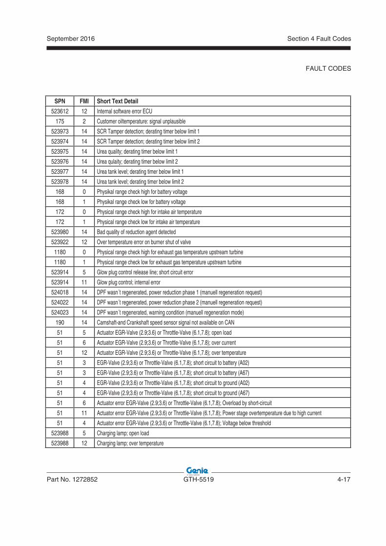
September 2016
Part No. 1272852 GTH-5519 4-17
Section 4 Fault Codes
SPN FMI Short Text Detail
523612 12 Internal software error ECU
175 2 Customer oiltemperature: signal unplausible
523973 14 SCR Tamper detection; derating timer below limit 1
523974 14 SCR Tamper detection; derating timer below limit 2
523975 14 Urea quality; derating timer below limit 1
523976 14 Urea qulaity; derating timer below limit 2
523977 14 Urea tank level; derating timer below limit 1
523978 14 Urea tank level; derating timer below limit 2
168 0 Physikal range check high for battery voltage
168 1 Physikal range check low for battery voltage
172 0 Physical range check high for intake air temperature
172 1 Physical range check low for intake air temperature
523980 14 Bad quality of reduction agent detected
523922 12 Over temperature error on burner shut of valve
1180 0 Physical range check high for exhaust gas temperature upstream turbine
1180 1 Physical range check low for exhaust gas temperature upstream turbine
523914 5 Glow plug control release line; short circuit error
523914 11 Glow plug control; internal error
524018 14 DPF wasn´t regenerated, power reduction phase 1 (manuell regeneration request)
524022 14 DPF wasn´t regenerated, power reduction phase 2 (manuell regeneration request)
524023 14 DPF wasn´t regenerated, warning condition (manuell regeneration mode)
190 14 Camshaft-and Crankshaft speed sensor signal not available on CAN
51 5 Actuator EGR-Valve (2.9;3.6) or Throttle-Valve (6.1,7.8); open load
51 6 Actuator EGR-Valve (2.9;3.6) or Throttle-Valve (6.1,7.8); over current
51 12 Actuator EGR-Valve (2.9;3.6) or Throttle-Valve (6.1,7.8); over temperature
51 3 EGR-Valve (2.9;3.6) or Throttle-Valve (6.1,7.8); short circuit to battery (A02)
51 3 EGR-Valve (2.9;3.6) or Throttle-Valve (6.1,7.8); short circuit to battery (A67)
51 4 EGR-Valve (2.9;3.6) or Throttle-Valve (6.1,7.8); short circuit to ground (A02)
51 4 EGR-Valve (2.9;3.6) or Throttle-Valve (6.1,7.8); short circuit to ground (A67)
51 6 Actuator error EGR-Valve (2.9;3.6) or Throttle-Valve (6.1,7.8); Overload by short-circuit
51 11 Actuator error EGR-Valve (2.9;3.6) or Throttle-Valve (6.1,7.8); Power stage overtemperature due to high current
51 4 Actuator error EGR-Valve (2.9;3.6) or Throttle-Valve (6.1,7.8); Voltage below threshold
523988 5 Charging lamp; open load
523988 12 Charging lamp; over temperature
FAULT CODES
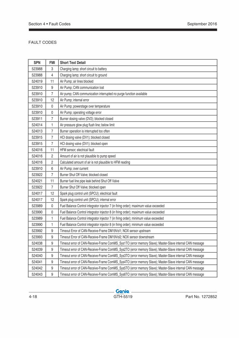
4-18 GTH-5519 Part No. 1272852
September 2016Section 4 • Fault Codes
SPN FMI Short Text Detail
523988 3 Charging lamp; short circuit to battery
523988 4 Charging lamp; short circuit to ground
524019 11 Air Pump; air lines blocked
523910 9 Air Pump; CAN communication lost
523910 7 Air pump; CAN communication interrupted no purge function available
523910 12 Air Pump; internal error
523910 0 Air Pump; powerstage over temperature
523910 0 Air Pump; operating voltage error
523911 7 Burner dosing valve (DV2); blocked closed
524014 1 Air pressure glow plug flush line; below limit
524013 7 Burner operation is interrupted too often
523915 7 HCI dosing valve (DV1); blocked closed
523915 7 HCI dosing valve (DV1); blocked open
524016 11 HFM sensor; electrical fault
524016 2 Amount of air is not plausible to pump speed
524016 2 Calculated amount of air is not plausible to HFM reading
523910 6 Air Pump; over current
523922 7 Burner Shut Off Valve; blocked closed
524021 11 Burner fuel line pipe leak behind Shut Off Valve
523922 7 Burner Shut Off Valve; blocked open
524017 12 Spark plug control unit (SPCU); electrical fault
524017 12 Spark plug control unit (SPCU); internal error
523989 0 Fuel Balance Control integrator injector 7 (in firing order); maximum value exceeded
523990 0 Fuel Balance Control integrator injector 8 (in firing order); maximum value exceeded
523989 1 Fuel Balance Control integrator injector 7 (in firing order); minimum value exceeded
523990 1 Fuel Balance Control integrator injector 8 (in firing order); minimum value exceeded
523992 9 Timeout Error of CAN-Receive-Frame DM19Vol1; NOX sensor upstream
523993 9 Timeout Error of CAN-Receive-Frame DM19Vol2; NOX sensor downstream
524038 9 Timeout error of CAN-Receive-Frame ComMS_Sys1TO (error memory Slave); Master-Slave internal CAN message
524039 9 Timeout error of CAN-Receive-Frame ComMS_Sys2TO (error memory Slave); Master-Slave internal CAN message
524040 9 Timeout error of CAN-Receive-Frame ComMS_Sys3TO (error memory Slave); Master-Slave internal CAN message
524041 9 Timeout error of CAN-Receive-Frame ComMS_Sys4TO (error memory Slave); Master-Slave internal CAN message
524042 9 Timeout error of CAN-Receive-Frame ComMS_Sys5TO (error memory Slave); Master-Slave internal CAN message
524043 9 Timeout error of CAN-Receive-Frame ComMS_Sys6TO (error memory Slave); Master-Slave internal CAN message
FAULT CODES
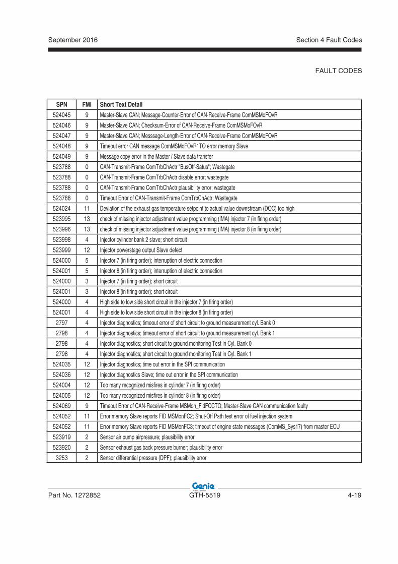
September 2016
Part No. 1272852 GTH-5519 4-19
Section 4 Fault Codes
SPN FMI Short Text Detail
524045 9 Master-Slave CAN; Message-Counter-Error of CAN-Receive-Frame ComMSMoFOvR
524046 9 Master-Slave CAN; Checksum-Error of CAN-Receive-Frame ComMSMoFOvR
524047 9 Master-Slave CAN; Messsage-Length-Error of CAN-Receive-Frame ComMSMoFOvR
524048 9 Timeout error CAN message ComMSMoFOvR1TO error memory Slave
524049 9 Message copy error in the Master / Slave data transfer
523788 0 CAN-Transmit-Frame ComTrbChActr "BusOff-Satus"; Wastegate
523788 0 CAN-Transmit-Frame ComTrbChActr disable error; wastegate
523788 0 CAN-Transmit-Frame ComTrbChActr plausibility error; wastegate
523788 0 Timeout Error of CAN-Transmit-Frame ComTrbChActr; Wastegate
524024 11 Deviation of the exhaust gas temperature setpoint to actual value downstream (DOC) too high
523995 13 check of missing injector adjustment value programming (IMA) injector 7 (in firing order)
523996 13 check of missing injector adjustment value programming (IMA) injector 8 (in firing order)
523998 4 Injector cylinder bank 2 slave; short circuit
523999 12 Injector powerstage output Slave defect
524000 5 Injector 7 (in firing order); interruption of electric connection
524001 5 Injector 8 (in firing order); interruption of electric connection
524000 3 Injector 7 (in firing order); short circuit
524001 3 Injector 8 (in firing order); short circuit
524000 4 High side to low side short circuit in the injector 7 (in firing order)
524001 4 High side to low side short circuit in the injector 8 (in firing order)
2797 4 Injector diagnostics; timeout error of short circuit to ground measurement cyl. Bank 0
2798 4 Injector diagnostics; timeout error of short circuit to ground measurement cyl. Bank 1
2798 4 Injector diagnostics; short circuit to ground monitoring Test in Cyl. Bank 0
2798 4 Injector diagnostics; short circuit to ground monitoring Test in Cyl. Bank 1
524035 12 Injector diagnostics; time out error in the SPI communication
524036 12 Injector diagnostics Slave; time out error in the SPI communication
524004 12 Too many recognized misfires in cylinder 7 (in firing order)
524005 12 Too many recognized misfires in cylinder 8 (in firing order)
524069 9 Timeout Error of CAN-Receive-Frame MSMon_FidFCCTO; Master-Slave CAN communication faulty
524052 11 Error memory Slave reports FID MSMonFC2; Shut-Off Path test error of fuel injection system
524052 11 Error memory Slave reports FID MSMonFC3; timeout of engine state messages (ComMS_Sys1 7) from master ECU
523919 2 Sensor air pump airpressure; plausibility error
523920 2 Sensor exhaust gas back pressure burner; plausibility error
3253 2 Sensor differential pressure (DPF); plausibility error
FAULT CODES
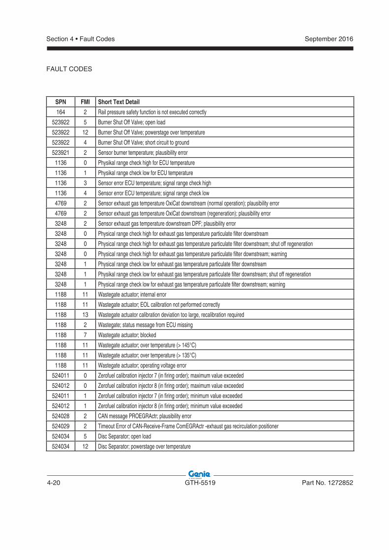
4-20 GTH-5519 Part No. 1272852
September 2016Section 4 • Fault Codes
SPN FMI Short Text Detail
164 2 Rail pressure safety function is not executed correctly
523922 5 Burner Shut Off Valve; open load
523922 12 Burner Shut Off Valve; powerstage over temperature
523922 4 Burner Shut Off Valve; short circuit to ground
523921 2 Sensor burner temperature; plausibility error
1136 0 Physikal range check high for ECU temperature
1136 1 Physikal range check low for ECU temperature
1136 3 Sensor error ECU temperature; signal range check high
1136 4 Sensor error ECU temperature; signal range check low
4769 2 Sensor exhaust gas temperature OxiCat downstream (normal operation); plausibility error
4769 2 Sensor exhaust gas temperature OxiCat downstream (regeneration); plausibility error
3248 2 Sensor exhaust gas temperature downstream DPF; plausibility error
3248 0 Physical range check high for exhaust gas temperature particulate filter downstream
3248 0 Physical range check high for exhaust gas temperature particulate filter downstream; shut off regeneration
3248 0 Physical range check high for exhaust gas temperature particulate filter downstream; warning
3248 1 Physical range check low for exhaust gas temperature particulate filter downstream
3248 1 Physikal range check low for exhaust gas temperature particulate filter downstream; shut off regeneration
3248 1 Physical range check low for exhaust gas temperature particulate filter downstream; warning
1188 11 Wastegate actuator; internal error
1188 11 Wastegate actuator; EOL calibration not performed correctly
1188 13 Wastegate actuator calibration deviation too large, recalibration required
1188 2 Wastegate; status message from ECU missing
1188 7 Wastegate actuator; blocked
1188 11 Wastegate actuator; over temperature (> 145°C)
1188 11 Wastegate actuator; over temperature (> 135°C)
1188 11 Wastegate actuator; operating voltage error
524011 0 Zerofuel calibration injector 7 (in firing order); maximum value exceeded
524012 0 Zerofuel calibration injector 8 (in firing order); maximum value exceeded
524011 1 Zerofuel calibration injector 7 (in firing order); minimum value exceeded
524012 1 Zerofuel calibration injector 8 (in firing order); minimum value exceeded
524028 2 CAN message PROEGRActr; plausibility error
524029 2 Timeout Error of CAN-Receive-Frame ComEGRActr -exhaust gas recirculation positioner
524034 5 Disc Separator; open load
524034 12 Disc Separator; powerstage over temperature
FAULT CODES
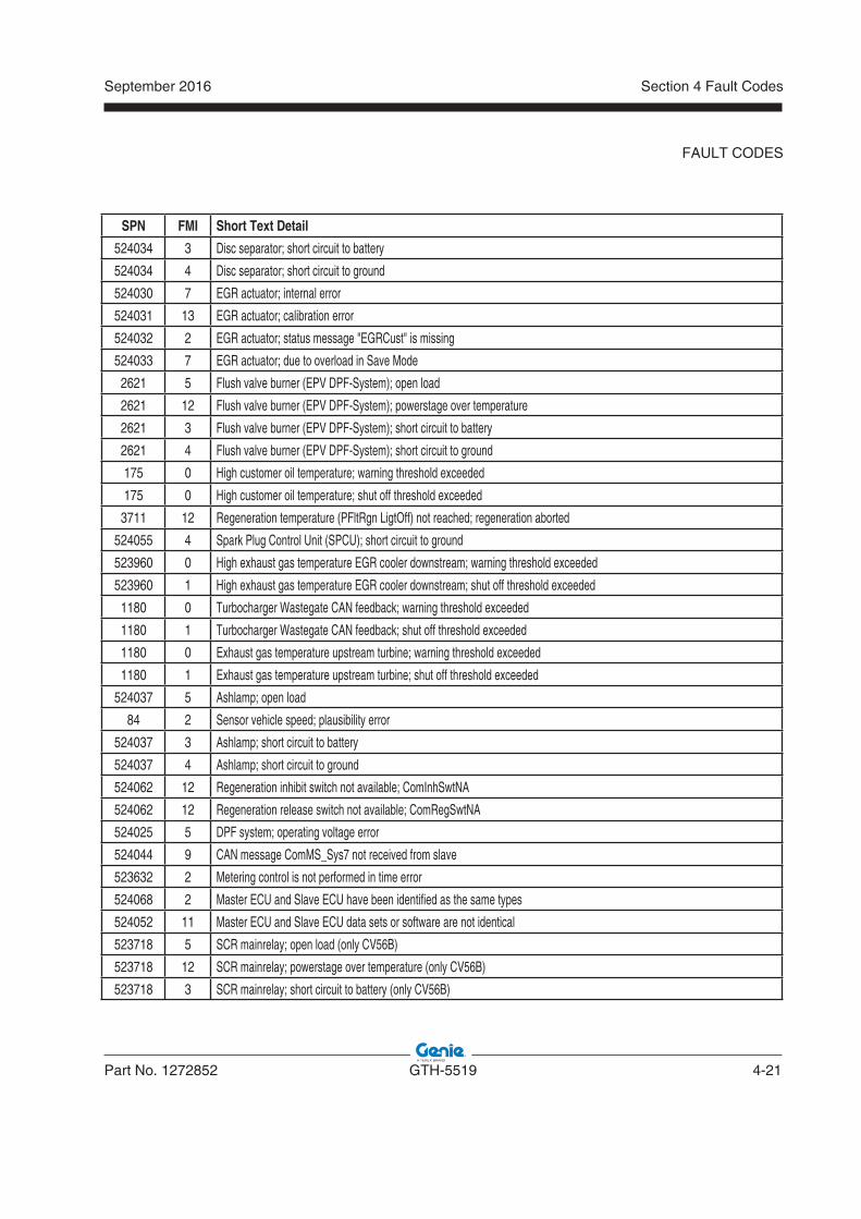
September 2016
Part No. 1272852 GTH-5519 4-21
Section 4 Fault Codes
SPN FMI Short Text Detail
524034 3 Disc separator; short circuit to battery
524034 4 Disc separator; short circuit to ground
524030 7 EGR actuator; internal error
524031 13 EGR actuator; calibration error
524032 2 EGR actuator; status message "EGRCust" is missing
524033 7 EGR actuator; due to overload in Save Mode
2621 5 Flush valve burner (EPV DPF-System); open load
2621 12 Flush valve burner (EPV DPF-System); powerstage over temperature
2621 3 Flush valve burner (EPV DPF-System); short circuit to battery
2621 4 Flush valve burner (EPV DPF-System); short circuit to ground
175 0 High customer oil temperature; warning threshold exceeded
175 0 High customer oil temperature; shut off threshold exceeded
3711 12 Regeneration temperature (PFltRgn LigtOff) not reached; regeneration aborted
524055 4 Spark Plug Control Unit (SPCU); short circuit to ground
523960 0 High exhaust gas temperature EGR cooler downstream; warning threshold exceeded
523960 1 High exhaust gas temperature EGR cooler downstream; shut off threshold exceeded
1180 0 Turbocharger Wastegate CAN feedback; warning threshold exceeded
1180 1 Turbocharger Wastegate CAN feedback; shut off threshold exceeded
1180 0 Exhaust gas temperature upstream turbine; warning threshold exceeded
1180 1 Exhaust gas temperature upstream turbine; shut off threshold exceeded
524037 5 Ashlamp; open load
84 2 Sensor vehicle speed; plausibility error
524037 3 Ashlamp; short circuit to battery
524037 4 Ashlamp; short circuit to ground
524062 12 Regeneration inhibit switch not available; ComInhSwtNA
524062 12 Regeneration release switch not available; ComRegSwtNA
524025 5 DPF system; operating voltage error
524044 9 CAN message ComMS_Sys7 not received from slave
523632 2 Metering control is not performed in time error
524068 2 Master ECU and Slave ECU have been identified as the same types
524052 11 Master ECU and Slave ECU data sets or software are not identical
523718 5 SCR mainrelay; open load (only CV56B)
523718 12 SCR mainrelay; powerstage over temperature (only CV56B)
523718 3 SCR mainrelay; short circuit to battery (only CV56B)
FAULT CODES
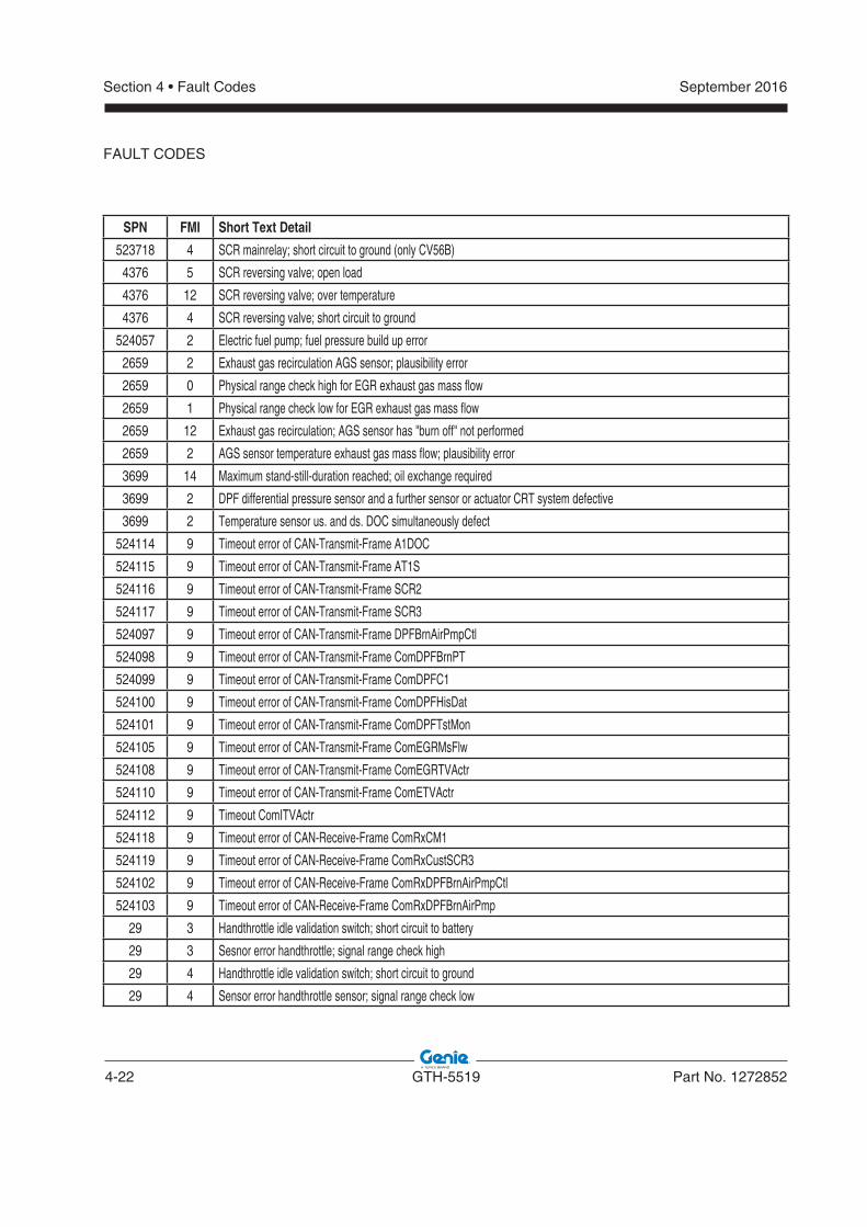
4-22 GTH-5519 Part No. 1272852
September 2016Section 4 • Fault Codes
SPN FMI Short Text Detail
523718 4 SCR mainrelay; short circuit to ground (only CV56B)
4376 5 SCR reversing valve; open load
4376 12 SCR reversing valve; over temperature
4376 4 SCR reversing valve; short circuit to ground
524057 2 Electric fuel pump; fuel pressure build up error
2659 2 Exhaust gas recirculation AGS sensor; plausibility error
2659 0 Physical range check high for EGR exhaust gas mass flow
2659 1 Physical range check low for EGR exhaust gas mass flow
2659 12 Exhaust gas recirculation; AGS sensor has "burn off" not performed
2659 2 AGS sensor temperature exhaust gas mass flow; plausibility error
3699 14 Maximum stand-still-duration reached; oil exchange required
3699 2 DPF differential pressure sensor and a further sensor or actuator CRT system defective
3699 2 Temperature sensor us. and ds. DOC simultaneously defect
524114 9 Timeout error of CAN-Transmit-Frame A1DOC
524115 9 Timeout error of CAN-Transmit-Frame AT1S
524116 9 Timeout error of CAN-Transmit-Frame SCR2
524117 9 Timeout error of CAN-Transmit-Frame SCR3
524097 9 Timeout error of CAN-Transmit-Frame DPFBrnAirPmpCtl
524098 9 Timeout error of CAN-Transmit-Frame ComDPFBrnPT
524099 9 Timeout error of CAN-Transmit-Frame ComDPFC1
524100 9 Timeout error of CAN-Transmit-Frame ComDPFHisDat
524101 9 Timeout error of CAN-Transmit-Frame ComDPFTstMon
524105 9 Timeout error of CAN-Transmit-Frame ComEGRMsFlw
524108 9 Timeout error of CAN-Transmit-Frame ComEGRTVActr
524110 9 Timeout error of CAN-Transmit-Frame ComETVActr
524112 9 Timeout ComITVActr
524118 9 Timeout error of CAN-Receive-Frame ComRxCM1
524119 9 Timeout error of CAN-Receive-Frame ComRxCustSCR3
524102 9 Timeout error of CAN-Receive-Frame ComRxDPFBrnAirPmpCtl
524103 9 Timeout error of CAN-Receive-Frame ComRxDPFBrnAirPmp
29 3 Handthrottle idle validation switch; short circuit to battery
29 3 Sesnor error handthrottle; signal range check high
29 4 Handthrottle idle validation switch; short circuit to ground
29 4 Sensor error handthrottle sensor; signal range check low
FAULT CODES
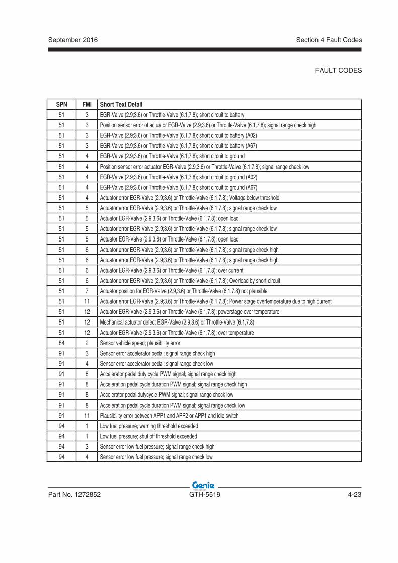
September 2016
Part No. 1272852 GTH-5519 4-23
Section 4 Fault Codes
SPN FMI Short Text Detail
51 3 EGR-Valve (2.9;3.6) or Throttle-Valve (6.1,7.8); short circuit to battery
51 3 Position sensor error of actuator EGR-Valve (2.9;3.6) or Throttle-Valve (6.1,7.8); signal range check high
51 3 EGR-Valve (2.9;3.6) or Throttle-Valve (6.1,7.8); short circuit to battery (A02)
51 3 EGR-Valve (2.9;3.6) or Throttle-Valve (6.1,7.8); short circuit to battery (A67)
51 4 EGR-Valve (2.9;3.6) or Throttle-Valve (6.1,7.8); short circuit to ground
51 4 Position sensor error actuator EGR-Valve (2.9;3.6) or Throttle-Valve (6.1,7.8); signal range check low
51 4 EGR-Valve (2.9;3.6) or Throttle-Valve (6.1,7.8); short circuit to ground (A02)
51 4 EGR-Valve (2.9;3.6) or Throttle-Valve (6.1,7.8); short circuit to ground (A67)
51 4 Actuator error EGR-Valve (2.9;3.6) or Throttle-Valve (6.1,7.8); Voltage below threshold
51 5 Actuator error EGR-Valve (2.9;3.6) or Throttle-Valve (6.1,7.8); signal range check low
51 5 Actuator EGR-Valve (2.9;3.6) or Throttle-Valve (6.1,7.8); open load
51 5 Actuator error EGR-Valve (2.9;3.6) or Throttle-Valve (6.1,7.8); signal range check low
51 5 Actuator EGR-Valve (2.9;3.6) or Throttle-Valve (6.1,7.8); open load
51 6 Actuator error EGR-Valve (2.9;3.6) or Throttle-Valve (6.1,7.8); signal range check high
51 6 Actuator error EGR-Valve (2.9;3.6) or Throttle-Valve (6.1,7.8); signal range check high
51 6 Actuator EGR-Valve (2.9;3.6) or Throttle-Valve (6.1,7.8); over current
51 6 Actuator error EGR-Valve (2.9;3.6) or Throttle-Valve (6.1,7.8); Overload by short-circuit
51 7 Actuator position for EGR-Valve (2.9,3.6) or Throttle-Valve (6.1,7.8) not plausible
51 11 Actuator error EGR-Valve (2.9;3.6) or Throttle-Valve (6.1,7.8); Power stage overtemperature due to high current
51 12 Actuator EGR-Valve (2.9;3.6) or Throttle-Valve (6.1,7.8); powerstage over temperature
51 12 Mechanical actuator defect EGR-Valve (2.9,3.6) or Throttle-Valve (6.1,7.8)
51 12 Actuator EGR-Valve (2.9;3.6) or Throttle-Valve (6.1,7.8); over temperature
84 2 Sensor vehicle speed; plausibility error
91 3 Sensor error accelerator pedal; signal range check high
91 4 Sensor error accelerator pedal; signal range check low
91 8 Accelerator pedal duty cycle PWM signal; signal range check high
91 8 Acceleration pedal cycle duration PWM signal; signal range check high
91 8 Accelerator pedal dutycycle PWM signal; signal range check low
91 8 Acceleration pedal cycle duration PWM signal; signal range check low
91 11 Plausibility error between APP1 and APP2 or APP1 and idle switch
94 1 Low fuel pressure; warning threshold exceeded
94 1 Low fuel pressure; shut off threshold exceeded
94 3 Sensor error low fuel pressure; signal range check high
94 4 Sensor error low fuel pressure; signal range check low
FAULT CODES
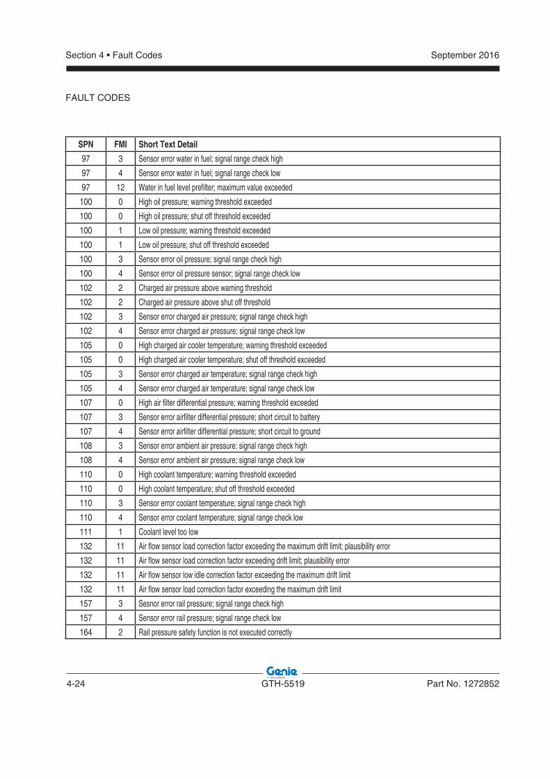
4-24 GTH-5519 Part No. 1272852
September 2016Section 4 • Fault Codes
SPN FMI Short Text Detail
97 3 Sensor error water in fuel; signal range check high
97 4 Sensor error water in fuel; signal range check low
97 12 Water in fuel level prefilter; maximum value exceeded
100 0 High oil pressure; warning threshold exceeded
100 0 High oil pressure; shut off threshold exceeded
100 1 Low oil pressure; warning threshold exceeded
100 1 Low oil pressure; shut off threshold exceeded
100 3 Sensor error oil pressure; signal range check high
100 4 Sensor error oil pressure sensor; signal range check low
102 2 Charged air pressure above warning threshold
102 2 Charged air pressure above shut off threshold
102 3 Sensor error charged air pressure; signal range check high
102 4 Sensor error charged air pressure; signal range check low
105 0 High charged air cooler temperature; warning threshold exceeded
105 0 High charged air cooler temperature; shut off threshold exceeded
105 3 Sensor error charged air temperature; signal range check high
105 4 Sensor error charged air temperature; signal range check low
107 0 High air filter differential pressure; warning threshold exceeded
107 3 Sensor error airfilter differential pressure; short circuit to battery
107 4 Sensor error airfilter differential pressure; short circuit to ground
108 3 Sensor error ambient air pressure; signal range check high
108 4 Sensor error ambient air pressure; signal range check low
110 0 High coolant temperature; warning threshold exceeded
110 0 High coolant temperature; shut off threshold exceeded
110 3 Sensor error coolant temperature; signal range check high
110 4 Sensor error coolant temperature; signal range check low
111 1 Coolant level too low
132 11 Air flow sensor load correction factor exceeding the maximum drift limit; plausibility error
132 11 Air flow sensor load correction factor exceeding drift limit; plausibility error
132 11 Air flow sensor low idle correction factor exceeding the maximum drift limit
132 11 Air flow sensor load correction factor exceeding the maximum drift limit
157 3 Sesnor error rail pressure; signal range check high
157 4 Sensor error rail pressure; signal range check low
164 2 Rail pressure safety function is not executed correctly
FAULT CODES
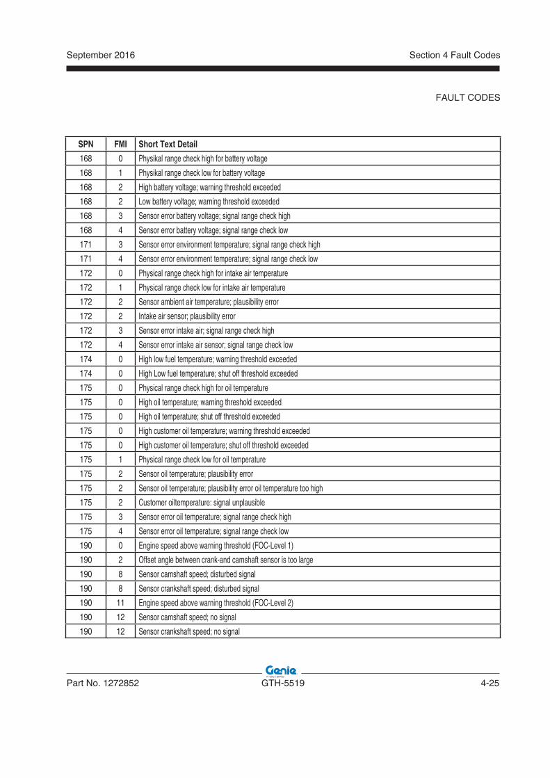
September 2016
Part No. 1272852 GTH-5519 4-25
Section 4 Fault Codes
SPN FMI Short Text Detail
168 0 Physikal range check high for battery voltage
168 1 Physikal range check low for battery voltage
168 2 High battery voltage; warning threshold exceeded
168 2 Low battery voltage; warning threshold exceeded
168 3 Sensor error battery voltage; signal range check high
168 4 Sensor error battery voltage; signal range check low
171 3 Sensor error environment temperature; signal range check high
171 4 Sensor error environment temperature; signal range check low
172 0 Physical range check high for intake air temperature
172 1 Physical range check low for intake air temperature
172 2 Sensor ambient air temperature; plausibility error
172 2 Intake air sensor; plausibility error
172 3 Sensor error intake air; signal range check high
172 4 Sensor error intake air sensor; signal range check low
174 0 High low fuel temperature; warning threshold exceeded
174 0 High Low fuel temperature; shut off threshold exceeded
175 0 Physical range check high for oil temperature
175 0 High oil temperature; warning threshold exceeded
175 0 High oil temperature; shut off threshold exceeded
175 0 High customer oil temperature; warning threshold exceeded
175 0 High customer oil temperature; shut off threshold exceeded
175 1 Physical range check low for oil temperature
175 2 Sensor oil temperature; plausibility error
175 2 Sensor oil temperature; plausibility error oil temperature too high
175 2 Customer oiltemperature: signal unplausible
175 3 Sensor error oil temperature; signal range check high
175 4 Sensor error oil temperature; signal range check low
190 0 Engine speed above warning threshold (FOC-Level 1)
190 2 Offset angle between crank-and camshaft sensor is too large
190 8 Sensor camshaft speed; disturbed signal
190 8 Sensor crankshaft speed; disturbed signal
190 11 Engine speed above warning threshold (FOC-Level 2)
190 12 Sensor camshaft speed; no signal
190 12 Sensor crankshaft speed; no signal
FAULT CODES
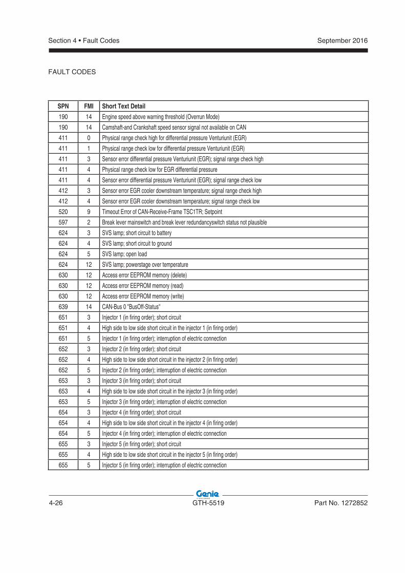
4-26 GTH-5519 Part No. 1272852
September 2016Section 4 • Fault Codes
SPN FMI Short Text Detail
190 14 Engine speed above warning threshold (Overrun Mode)
190 14 Camshaft-and Crankshaft speed sensor signal not available on CAN
411 0 Physical range check high for differential pressure Venturiunit (EGR)
411 1 Physical range check low for differential pressure Venturiunit (EGR)
411 3 Sensor error differential pressure Venturiunit (EGR); signal range check high
411 4 Physical range check low for EGR differential pressure
411 4 Sensor error differential pressure Venturiunit (EGR); signal range check low
412 3 Sensor error EGR cooler downstream temperature; signal range check high
412 4 Sensor error EGR cooler downstream temperature; signal range check low
520 9 Timeout Error of CAN-Receive-Frame TSC1TR; Setpoint
597 2 Break lever mainswitch and break lever redundancyswitch status not plausible
624 3 SVS lamp; short circuit to battery
624 4 SVS lamp; short circuit to ground
624 5 SVS lamp; open load
624 12 SVS lamp; powerstage over temperature
630 12 Access error EEPROM memory (delete)
630 12 Access error EEPROM memory (read)
630 12 Access error EEPROM memory (write)
639 14 CAN-Bus 0 "BusOff-Status"
651 3 Injector 1 (in firing order); short circuit
651 4 High side to low side short circuit in the injector 1 (in firing order)
651 5 Injector 1 (in firing order); interruption of electric connection
652 3 Injector 2 (in firing order); short circuit
652 4 High side to low side short circuit in the injector 2 (in firing order)
652 5 Injector 2 (in firing order); interruption of electric connection
653 3 Injector 3 (in firing order); short circuit
653 4 High side to low side short circuit in the injector 3 (in firing order)
653 5 Injector 3 (in firing order); interruption of electric connection
654 3 Injector 4 (in firing order); short circuit
654 4 High side to low side short circuit in the injector 4 (in firing order)
654 5 Injector 4 (in firing order); interruption of electric connection
655 3 Injector 5 (in firing order); short circuit
655 4 High side to low side short circuit in the injector 5 (in firing order)
655 5 Injector 5 (in firing order); interruption of electric connection
FAULT CODES
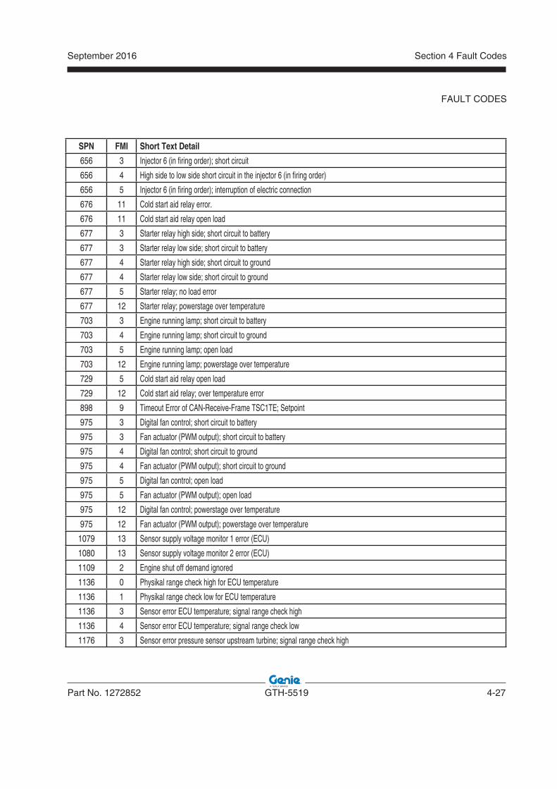
September 2016
Part No. 1272852 GTH-5519 4-27
Section 4 Fault Codes
SPN FMI Short Text Detail
656 3 Injector 6 (in firing order); short circuit
656 4 High side to low side short circuit in the injector 6 (in firing order)
656 5 Injector 6 (in firing order); interruption of electric connection
676 11 Cold start aid relay error.
676 11 Cold start aid relay open load
677 3 Starter relay high side; short circuit to battery
677 3 Starter relay low side; short circuit to battery
677 4 Starter relay high side; short circuit to ground
677 4 Starter relay low side; short circuit to ground
677 5 Starter relay; no load error
677 12 Starter relay; powerstage over temperature
703 3 Engine running lamp; short circuit to battery
703 4 Engine running lamp; short circuit to ground
703 5 Engine running lamp; open load
703 12 Engine running lamp; powerstage over temperature
729 5 Cold start aid relay open load
729 12 Cold start aid relay; over temperature error
898 9 Timeout Error of CAN-Receive-Frame TSC1TE; Setpoint
975 3 Digital fan control; short circuit to battery
975 3 Fan actuator (PWM output); short circuit to battery
975 4 Digital fan control; short circuit to ground
975 4 Fan actuator (PWM output); short circuit to ground
975 5 Digital fan control; open load
975 5 Fan actuator (PWM output); open load
975 12 Digital fan control; powerstage over temperature
975 12 Fan actuator (PWM output); powerstage over temperature
1079 13 Sensor supply voltage monitor 1 error (ECU)
1080 13 Sensor supply voltage monitor 2 error (ECU)
1109 2 Engine shut off demand ignored
1136 0 Physikal range check high for ECU temperature
1136 1 Physikal range check low for ECU temperature
1136 3 Sensor error ECU temperature; signal range check high
1136 4 Sensor error ECU temperature; signal range check low
1176 3 Sensor error pressure sensor upstream turbine; signal range check high
FAULT CODES
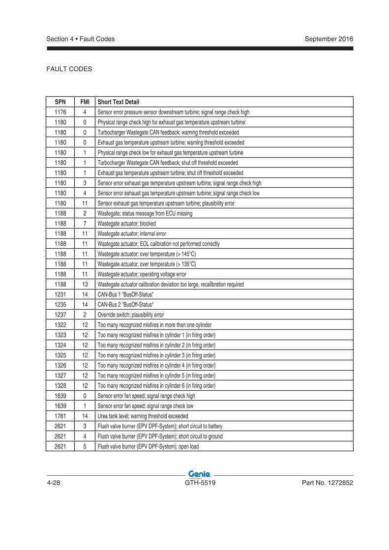
4-28 GTH-5519 Part No. 1272852
September 2016Section 4 • Fault Codes
SPN FMI Short Text Detail
1176 4 Sensor error pressure sensor downstream turbine; signal range check high
1180 0 Physical range check high for exhaust gas temperature upstream turbine
1180 0 Turbocharger Wastegate CAN feedback; warning threshold exceeded
1180 0 Exhaust gas temperature upstream turbine; warning threshold exceeded
1180 1 Physical range check low for exhaust gas temperature upstream turbine
1180 1 Turbocharger Wastegate CAN feedback; shut off threshold exceeded
1180 1 Exhaust gas temperature upstream turbine; shut off threshold exceeded
1180 3 Sensor error exhaust gas temperature upstream turbine; signal range check high
1180 4 Sensor error exhaust gas temperature upstream turbine; signal range check low
1180 11 Sensor exhaust gas temperature upstream turbine; plausibility error
1188 2 Wastegate; status message from ECU missing
1188 7 Wastegate actuator; blocked
1188 11 Wastegate actuator; internal error
1188 11 Wastegate actuator; EOL calibration not performed correctly
1188 11 Wastegate actuator; over temperature (> 145°C)
1188 11 Wastegate actuator; over temperature (> 135°C)
1188 11 Wastegate actuator; operating voltage error
1188 13 Wastegate actuator calibration deviation too large, recalibration required
1231 14 CAN-Bus 1 "BusOff-Status"
1235 14 CAN-Bus 2 "BusOff-Status"
1237 2 Override switch; plausibility error
1322 12 Too many recognized misfires in more than one cylinder
1323 12 Too many recognized misfires in cylinder 1 (in firing order)
1324 12 Too many recognized misfires in cylinder 2 (in firing order)
1325 12 Too many recognized misfires in cylinder 3 (in firing order)
1326 12 Too many recognized misfires in cylinder 4 (in firing order)
1327 12 Too many recognized misfires in cylinder 5 (in firing order)
1328 12 Too many recognized misfires in cylinder 6 (in firing order)
1639 0 Sensor error fan speed; signal range check high
1639 1 Sensor error fan speed; signal range check low
1761 14 Urea tank level; warning threshold exceeded
2621 3 Flush valve burner (EPV DPF-System); short circuit to battery
2621 4 Flush valve burner (EPV DPF-System); short circuit to ground
2621 5 Flush valve burner (EPV DPF-System); open load
FAULT CODES
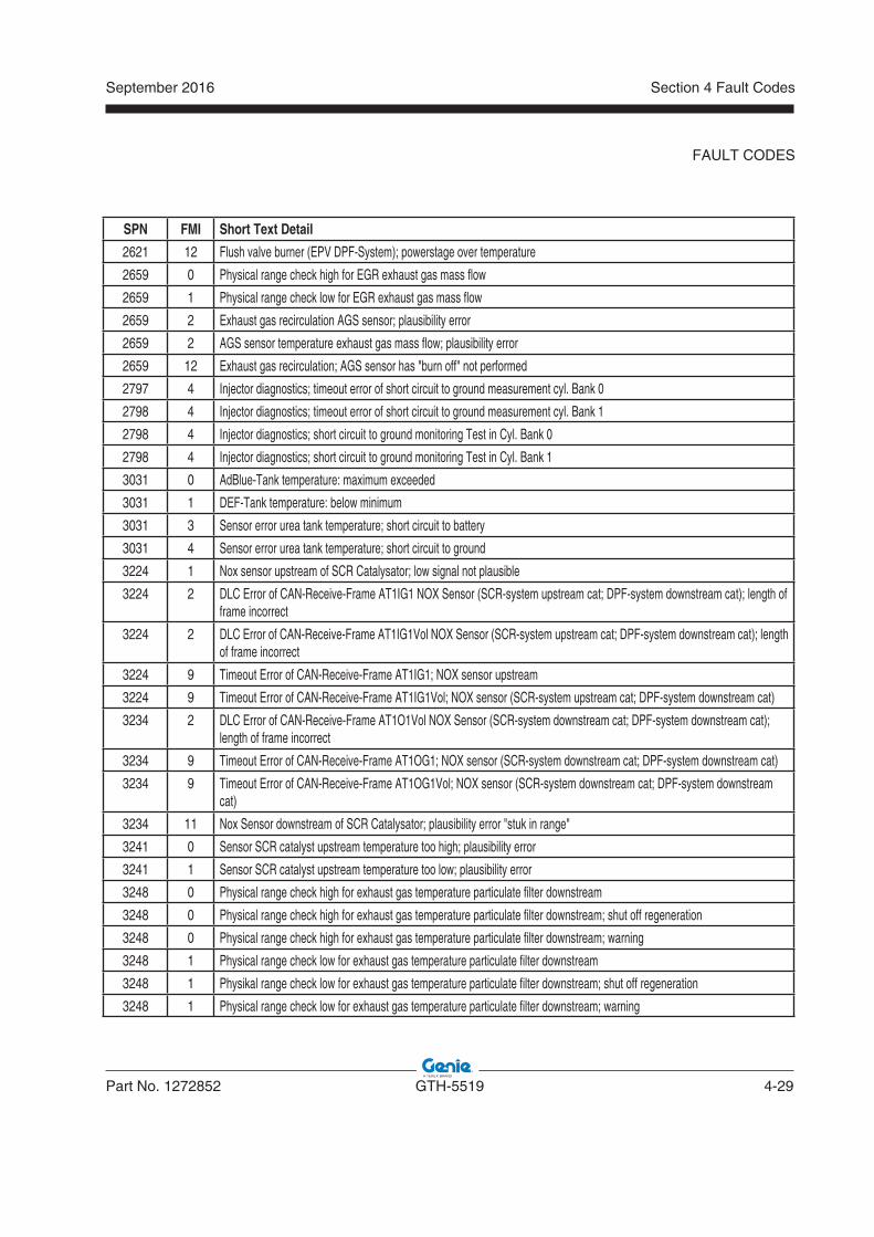
September 2016
Part No. 1272852 GTH-5519 4-29
Section 4 Fault Codes
SPN FMI Short Text Detail
2621 12 Flush valve burner (EPV DPF-System); powerstage over temperature
2659 0 Physical range check high for EGR exhaust gas mass flow
2659 1 Physical range check low for EGR exhaust gas mass flow
2659 2 Exhaust gas recirculation AGS sensor; plausibility error
2659 2 AGS sensor temperature exhaust gas mass flow; plausibility error
2659 12 Exhaust gas recirculation; AGS sensor has "burn off" not performed
2797 4 Injector diagnostics; timeout error of short circuit to ground measurement cyl. Bank 0
2798 4 Injector diagnostics; timeout error of short circuit to ground measurement cyl. Bank 1
2798 4 Injector diagnostics; short circuit to ground monitoring Test in Cyl. Bank 0
2798 4 Injector diagnostics; short circuit to ground monitoring Test in Cyl. Bank 1
3031 0 AdBlue-Tank temperature: maximum exceeded
3031 1 DEF-Tank temperature: below minimum
3031 3 Sensor error urea tank temperature; short circuit to battery
3031 4 Sensor error urea tank temperature; short circuit to ground
3224 1 Nox sensor upstream of SCR Catalysator; low signal not plausible
3224 2 DLC Error of CAN-Receive-Frame AT1IG1 NOX Sensor (SCR-system upstream cat; DPF-system downstream cat); length of frame incorrect
3224 2 DLC Error of CAN-Receive-Frame AT1IG1Vol NOX Sensor (SCR-system upstream cat; DPF-system downstream cat); length of frame incorrect
3224 9 Timeout Error of CAN-Receive-Frame AT1IG1; NOX sensor upstream
3224 9 Timeout Error of CAN-Receive-Frame AT1IG1Vol; NOX sensor (SCR-system upstream cat; DPF-system downstream cat)
3234 2 DLC Error of CAN-Receive-Frame AT1O1Vol NOX Sensor (SCR-system downstream cat; DPF-system downstream cat); length of frame incorrect
3234 9 Timeout Error of CAN-Receive-Frame AT1OG1; NOX sensor (SCR-system downstream cat; DPF-system downstream cat)
3234 9 Timeout Error of CAN-Receive-Frame AT1OG1Vol; NOX sensor (SCR-system downstream cat; DPF-system downstream cat)
3234 11 Nox Sensor downstream of SCR Catalysator; plausibility error "stuk in range"
3241 0 Sensor SCR catalyst upstream temperature too high; plausibility error
3241 1 Sensor SCR catalyst upstream temperature too low; plausibility error
3248 0 Physical range check high for exhaust gas temperature particulate filter downstream
3248 0 Physical range check high for exhaust gas temperature particulate filter downstream; shut off regeneration
3248 0 Physical range check high for exhaust gas temperature particulate filter downstream; warning
3248 1 Physical range check low for exhaust gas temperature particulate filter downstream
3248 1 Physikal range check low for exhaust gas temperature particulate filter downstream; shut off regeneration
3248 1 Physical range check low for exhaust gas temperature particulate filter downstream; warning
FAULT CODES
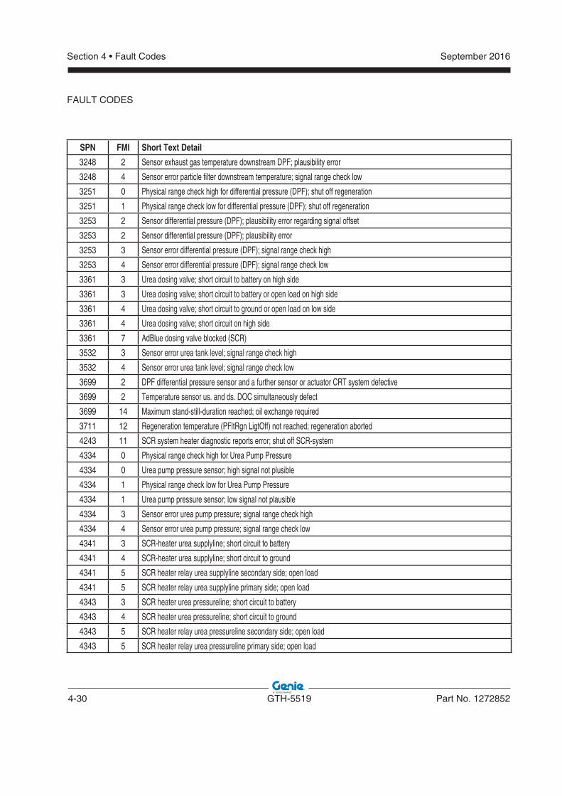
4-30 GTH-5519 Part No. 1272852
September 2016Section 4 • Fault Codes
SPN FMI Short Text Detail
3248 2 Sensor exhaust gas temperature downstream DPF; plausibility error
3248 4 Sensor error particle filter downstream temperature; signal range check low
3251 0 Physical range check high for differential pressure (DPF); shut off regeneration
3251 1 Physical range check low for differential pressure (DPF); shut off regeneration
3253 2 Sensor differential pressure (DPF); plausibility error regarding signal offset
3253 2 Sensor differential pressure (DPF); plausibility error
3253 3 Sensor error differential pressure (DPF); signal range check high
3253 4 Sensor error differential pressure (DPF); signal range check low
3361 3 Urea dosing valve; short circuit to battery on high side
3361 3 Urea dosing valve; short circuit to battery or open load on high side
3361 4 Urea dosing valve; short circuit to ground or open load on low side
3361 4 Urea dosing valve; short circuit on high side
3361 7 AdBlue dosing valve blocked (SCR)
3532 3 Sensor error urea tank level; signal range check high
3532 4 Sensor error urea tank level; signal range check low
3699 2 DPF differential pressure sensor and a further sensor or actuator CRT system defective
3699 2 Temperature sensor us. and ds. DOC simultaneously defect
3699 14 Maximum stand-still-duration reached; oil exchange required
3711 12 Regeneration temperature (PFltRgn LigtOff) not reached; regeneration aborted
4243 11 SCR system heater diagnostic reports error; shut off SCR-system
4334 0 Physical range check high for Urea Pump Pressure
4334 0 Urea pump pressure sensor; high signal not plusible
4334 1 Physical range check low for Urea Pump Pressure
4334 1 Urea pump pressure sensor; low signal not plausible
4334 3 Sensor error urea pump pressure; signal range check high
4334 4 Sensor error urea pump pressure; signal range check low
4341 3 SCR-heater urea supplyline; short circuit to battery
4341 4 SCR-heater urea supplyline; short circuit to ground
4341 5 SCR heater relay urea supplyline secondary side; open load
4341 5 SCR heater relay urea supplyline primary side; open load
4343 3 SCR heater urea pressureline; short circuit to battery
4343 4 SCR heater urea pressureline; short circuit to ground
4343 5 SCR heater relay urea pressureline secondary side; open load
4343 5 SCR heater relay urea pressureline primary side; open load
FAULT CODES
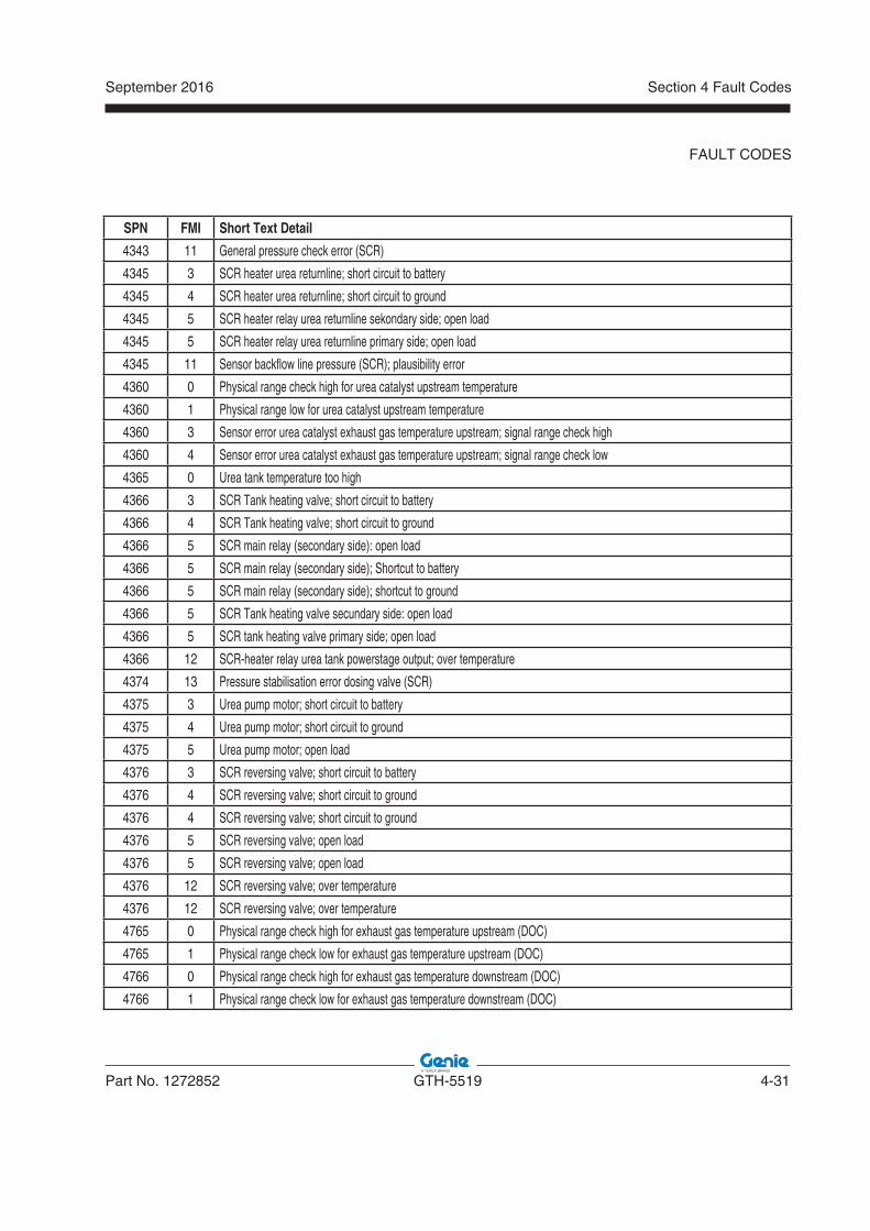
September 2016
Part No. 1272852 GTH-5519 4-31
Section 4 Fault Codes
SPN FMI Short Text Detail
4343 11 General pressure check error (SCR)
4345 3 SCR heater urea returnline; short circuit to battery
4345 4 SCR heater urea returnline; short circuit to ground
4345 5 SCR heater relay urea returnline sekondary side; open load
4345 5 SCR heater relay urea returnline primary side; open load
4345 11 Sensor backflow line pressure (SCR); plausibility error
4360 0 Physical range check high for urea catalyst upstream temperature
4360 1 Physical range low for urea catalyst upstream temperature
4360 3 Sensor error urea catalyst exhaust gas temperature upstream; signal range check high
4360 4 Sensor error urea catalyst exhaust gas temperature upstream; signal range check low
4365 0 Urea tank temperature too high
4366 3 SCR Tank heating valve; short circuit to battery
4366 4 SCR Tank heating valve; short circuit to ground
4366 5 SCR main relay (secondary side): open load
4366 5 SCR main relay (secondary side); Shortcut to battery
4366 5 SCR main relay (secondary side); shortcut to ground
4366 5 SCR Tank heating valve secundary side: open load
4366 5 SCR tank heating valve primary side; open load
4366 12 SCR-heater relay urea tank powerstage output; over temperature
4374 13 Pressure stabilisation error dosing valve (SCR)
4375 3 Urea pump motor; short circuit to battery
4375 4 Urea pump motor; short circuit to ground
4375 5 Urea pump motor; open load
4376 3 SCR reversing valve; short circuit to battery
4376 4 SCR reversing valve; short circuit to ground
4376 4 SCR reversing valve; short circuit to ground
4376 5 SCR reversing valve; open load
4376 5 SCR reversing valve; open load
4376 12 SCR reversing valve; over temperature
4376 12 SCR reversing valve; over temperature
4765 0 Physical range check high for exhaust gas temperature upstream (DOC)
4765 1 Physical range check low for exhaust gas temperature upstream (DOC)
4766 0 Physical range check high for exhaust gas temperature downstream (DOC)
4766 1 Physical range check low for exhaust gas temperature downstream (DOC)
FAULT CODES
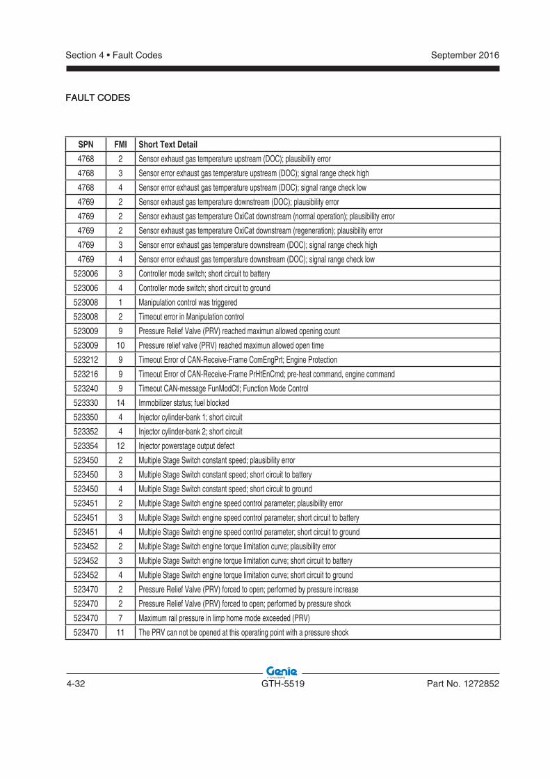
4-32 GTH-5519 Part No. 1272852
September 2016Section 4 • Fault Codes
FAULT CODES
SPN FMI Short Text Detail
4768 2 Sensor exhaust gas temperature upstream (DOC); plausibility error
4768 3 Sensor error exhaust gas temperature upstream (DOC); signal range check high
4768 4 Sensor error exhaust gas temperature upstream (DOC); signal range check low
4769 2 Sensor exhaust gas temperature downstream (DOC); plausibility error
4769 2 Sensor exhaust gas temperature OxiCat downstream (normal operation); plausibility error
4769 2 Sensor exhaust gas temperature OxiCat downstream (regeneration); plausibility error
4769 3 Sensor error exhaust gas temperature downstream (DOC); signal range check high
4769 4 Sensor error exhaust gas temperature downstream (DOC); signal range check low
523006 3 Controller mode switch; short circuit to battery
523006 4 Controller mode switch; short circuit to ground
523008 1 Manipulation control was triggered
523008 2 Timeout error in Manipulation control
523009 9 Pressure Relief Valve (PRV) reached maximun allowed opening count
523009 10 Pressure relief valve (PRV) reached maximun allowed open time
523212 9 Timeout Error of CAN-Receive-Frame ComEngPrt; Engine Protection
523216 9 Timeout Error of CAN-Receive-Frame PrHtEnCmd; pre-heat command, engine command
523240 9 Timeout CAN-message FunModCtl; Function Mode Control
523330 14 Immobilizer status; fuel blocked
523350 4 Injector cylinder-bank 1; short circuit
523352 4 Injector cylinder-bank 2; short circuit
523354 12 Injector powerstage output defect
523450 2 Multiple Stage Switch constant speed; plausibility error
523450 3 Multiple Stage Switch constant speed; short circuit to battery
523450 4 Multiple Stage Switch constant speed; short circuit to ground
523451 2 Multiple Stage Switch engine speed control parameter; plausibility error
523451 3 Multiple Stage Switch engine speed control parameter; short circuit to battery
523451 4 Multiple Stage Switch engine speed control parameter; short circuit to ground
523452 2 Multiple Stage Switch engine torque limitation curve; plausibility error
523452 3 Multiple Stage Switch engine torque limitation curve; short circuit to battery
523452 4 Multiple Stage Switch engine torque limitation curve; short circuit to ground
523470 2 Pressure Relief Valve (PRV) forced to open; performed by pressure increase
523470 2 Pressure Relief Valve (PRV) forced to open; performed by pressure shock
523470 7 Maximum rail pressure in limp home mode exceeded (PRV)
523470 11 The PRV can not be opened at this operating point with a pressure shock
FAULT CODES
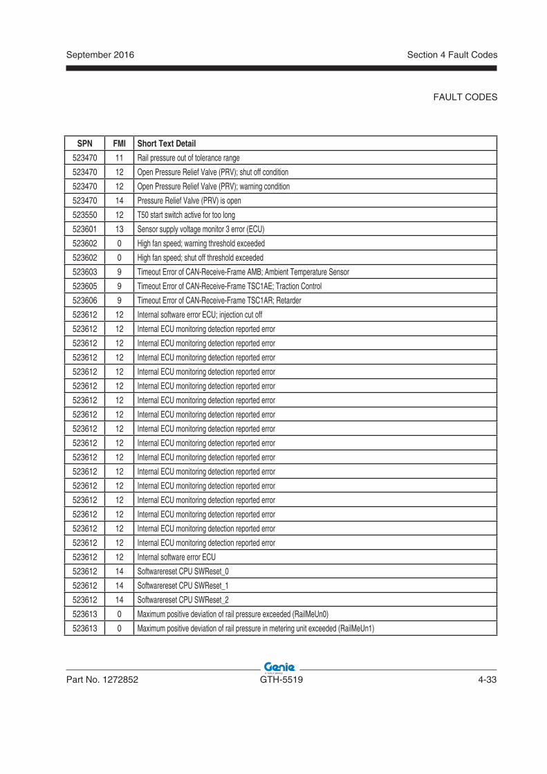
September 2016
Part No. 1272852 GTH-5519 4-33
Section 4 Fault Codes
SPN FMI Short Text Detail
523470 11 Rail pressure out of tolerance range
523470 12 Open Pressure Relief Valve (PRV); shut off condition
523470 12 Open Pressure Relief Valve (PRV); warning condition
523470 14 Pressure Relief Valve (PRV) is open
523550 12 T50 start switch active for too long
523601 13 Sensor supply voltage monitor 3 error (ECU)
523602 0 High fan speed; warning threshold exceeded
523602 0 High fan speed; shut off threshold exceeded
523603 9 Timeout Error of CAN-Receive-Frame AMB; Ambient Temperature Sensor
523605 9 Timeout Error of CAN-Receive-Frame TSC1AE; Traction Control
523606 9 Timeout Error of CAN-Receive-Frame TSC1AR; Retarder
523612 12 Internal software error ECU; injection cut off
523612 12 Internal ECU monitoring detection reported error
523612 12 Internal ECU monitoring detection reported error
523612 12 Internal ECU monitoring detection reported error
523612 12 Internal ECU monitoring detection reported error
523612 12 Internal ECU monitoring detection reported error
523612 12 Internal ECU monitoring detection reported error
523612 12 Internal ECU monitoring detection reported error
523612 12 Internal ECU monitoring detection reported error
523612 12 Internal ECU monitoring detection reported error
523612 12 Internal ECU monitoring detection reported error
523612 12 Internal ECU monitoring detection reported error
523612 12 Internal ECU monitoring detection reported error
523612 12 Internal ECU monitoring detection reported error
523612 12 Internal ECU monitoring detection reported error
523612 12 Internal ECU monitoring detection reported error
523612 12 Internal ECU monitoring detection reported error
523612 12 Internal software error ECU
523612 14 Softwarereset CPU SWReset_0
523612 14 Softwarereset CPU SWReset_1
523612 14 Softwarereset CPU SWReset_2
523613 0 Maximum positive deviation of rail pressure exceeded (RailMeUn0)
523613 0 Maximum positive deviation of rail pressure in metering unit exceeded (RailMeUn1)
FAULT CODES
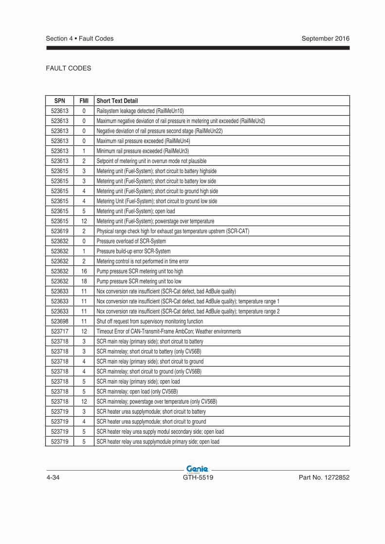
4-34 GTH-5519 Part No. 1272852
September 2016Section 4 • Fault Codes
SPN FMI Short Text Detail
523613 0 Railsystem leakage detected (RailMeUn10)
523613 0 Maximum negative deviation of rail pressure in metering unit exceeded (RailMeUn2)
523613 0 Negative deviation of rail pressure second stage (RailMeUn22)
523613 0 Maximum rail pressure exceeded (RailMeUn4)
523613 1 Minimum rail pressure exceeded (RailMeUn3)
523613 2 Setpoint of metering unit in overrun mode not plausible
523615 3 Metering unit (Fuel-System); short circuit to battery highside
523615 3 Metering unit (Fuel-System); short circuit to battery low side
523615 4 Metering unit (Fuel-System); short circuit to ground high side
523615 4 Metering Unit (Fuel-System); short circuit to ground low side
523615 5 Metering unit (Fuel-System); open load
523615 12 Metering unit (Fuel-System); powerstage over temperature
523619 2 Physical range check high for exhaust gas temperature upstrem (SCR-CAT)
523632 0 Pressure overload of SCR-System
523632 1 Pressure build-up error SCR-System
523632 2 Metering control is not performed in time error
523632 16 Pump pressure SCR metering unit too high
523632 18 Pump pressure SCR metering unit too low
523633 11 Nox conversion rate insufficient (SCR-Cat defect, bad AdBule quality)
523633 11 Nox conversion rate insufficient (SCR-Cat defect, bad AdBule quality); temperature range 1
523633 11 Nox conversion rate insufficient (SCR-Cat defect, bad AdBule quality); temperature range 2
523698 11 Shut off request from supervisory monitoring function
523717 12 Timeout Error of CAN-Transmit-Frame AmbCon; Weather environments
523718 3 SCR main relay (primary side); short circuit to battery
523718 3 SCR mainrelay; short circuit to battery (only CV56B)
523718 4 SCR main relay (primary side); short circuit to ground
523718 4 SCR mainrelay; short circuit to ground (only CV56B)
523718 5 SCR main relay (primary side); open load
523718 5 SCR mainrelay; open load (only CV56B)
523718 12 SCR mainrelay; powerstage over temperature (only CV56B)
523719 3 SCR heater urea supplymodule; short circuit to battery
523719 4 SCR heater urea supplymodule; short circuit to ground
523719 5 SCR heater relay urea supply modul secondary side; open load
523719 5 SCR heater relay urea supplymodule primary side; open load
FAULT CODES
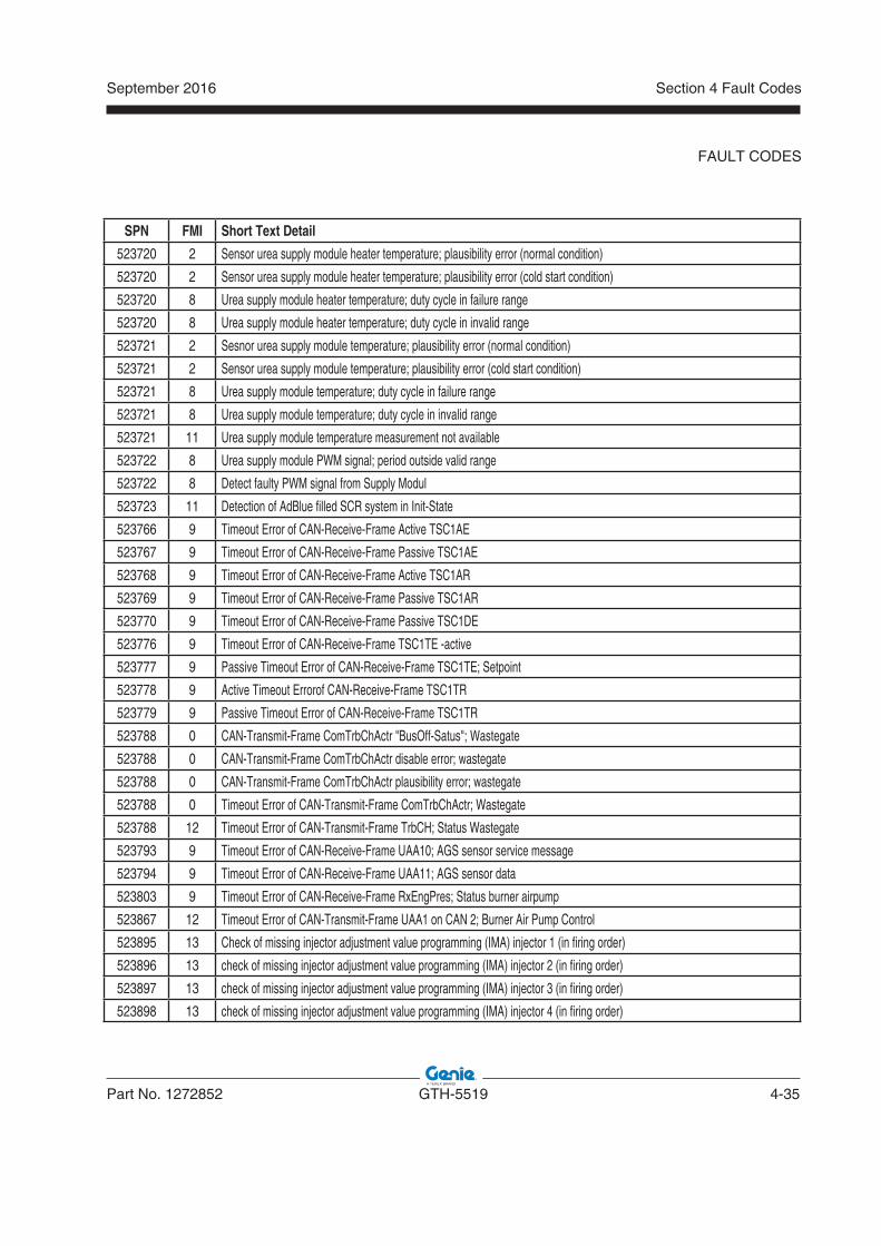
September 2016
Part No. 1272852 GTH-5519 4-35
Section 4 Fault Codes
FAULT CODES
SPN FMI Short Text Detail
523720 2 Sensor urea supply module heater temperature; plausibility error (normal condition)
523720 2 Sensor urea supply module heater temperature; plausibility error (cold start condition)
523720 8 Urea supply module heater temperature; duty cycle in failure range
523720 8 Urea supply module heater temperature; duty cycle in invalid range
523721 2 Sesnor urea supply module temperature; plausibility error (normal condition)
523721 2 Sensor urea supply module temperature; plausibility error (cold start condition)
523721 8 Urea supply module temperature; duty cycle in failure range
523721 8 Urea supply module temperature; duty cycle in invalid range
523721 11 Urea supply module temperature measurement not available
523722 8 Urea supply module PWM signal; period outside valid range
523722 8 Detect faulty PWM signal from Supply Modul
523723 11 Detection of AdBlue filled SCR system in Init-State
523766 9 Timeout Error of CAN-Receive-Frame Active TSC1AE
523767 9 Timeout Error of CAN-Receive-Frame Passive TSC1AE
523768 9 Timeout Error of CAN-Receive-Frame Active TSC1AR
523769 9 Timeout Error of CAN-Receive-Frame Passive TSC1AR
523770 9 Timeout Error of CAN-Receive-Frame Passive TSC1DE
523776 9 Timeout Error of CAN-Receive-Frame TSC1TE -active
523777 9 Passive Timeout Error of CAN-Receive-Frame TSC1TE; Setpoint
523778 9 Active Timeout Errorof CAN-Receive-Frame TSC1TR
523779 9 Passive Timeout Error of CAN-Receive-Frame TSC1TR
523788 0 CAN-Transmit-Frame ComTrbChActr "BusOff-Satus"; Wastegate
523788 0 CAN-Transmit-Frame ComTrbChActr disable error; wastegate
523788 0 CAN-Transmit-Frame ComTrbChActr plausibility error; wastegate
523788 0 Timeout Error of CAN-Transmit-Frame ComTrbChActr; Wastegate
523788 12 Timeout Error of CAN-Transmit-Frame TrbCH; Status Wastegate
523793 9 Timeout Error of CAN-Receive-Frame UAA10; AGS sensor service message
523794 9 Timeout Error of CAN-Receive-Frame UAA11; AGS sensor data
523803 9 Timeout Error of CAN-Receive-Frame RxEngPres; Status burner airpump
523867 12 Timeout Error of CAN-Transmit-Frame UAA1 on CAN 2; Burner Air Pump Control
523895 13 Check of missing injector adjustment value programming (IMA) injector 1 (in firing order)
523896 13 check of missing injector adjustment value programming (IMA) injector 2 (in firing order)
523897 13 check of missing injector adjustment value programming (IMA) injector 3 (in firing order)
523898 13 check of missing injector adjustment value programming (IMA) injector 4 (in firing order)
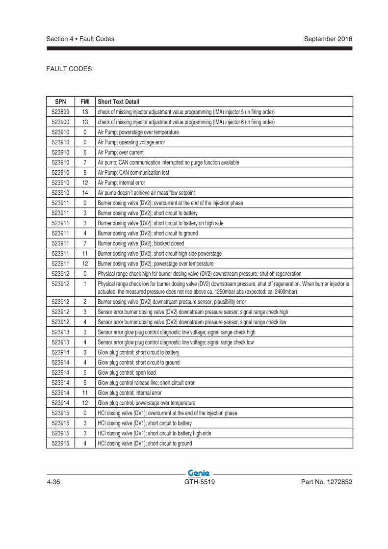
4-36 GTH-5519 Part No. 1272852
September 2016Section 4 • Fault Codes
SPN FMI Short Text Detail
523899 13 check of missing injector adjustment value programming (IMA) injector 5 (in firing order)
523900 13 check of missing injector adjustment value programming (IMA) injector 6 (in firing order)
523910 0 Air Pump; powerstage over temperature
523910 0 Air Pump; operating voltage error
523910 6 Air Pump; over current
523910 7 Air pump; CAN communication interrupted no purge function available
523910 9 Air Pump; CAN communication lost
523910 12 Air Pump; internal error
523910 14 Air pump doesn´t achieve air mass flow setpoint
523911 0 Burner dosing valve (DV2); overcurrent at the end of the injection phase
523911 3 Burner dosing valve (DV2); short circuit to battery
523911 3 Burner dosing valve (DV2); short circuit to battery on high side
523911 4 Burner dosing valve (DV2); short circuit to ground
523911 7 Burner dosing valve (DV2); blocked closed
523911 11 Burner dosing valve (DV2); short circuit high side powerstage
523911 12 Burner dosing valve (DV2); powerstage over temperature
523912 0 Physical range check high for burner dosing valve (DV2) downstream pressure; shut off regeneration
523912 1 Physical range check low for burner dosing valve (DV2) downstream pressure; shut off regeneration. When burner injector is actuated, the measured pressure does not rise above ca. 1250mbar abs (expected: ca. 2400mbar).
523912 2 Burner dosing valve (DV2) downstream pressure sensor; plausibility error
523912 3 Sensor error burner dosing valve (DV2) downstream pressure sensor; signal range check high
523912 4 Sensor error burner dosing valve (DV2) downstream pressure sensor; signal range check low
523913 3 Sensor error glow plug control diagnostic line voltage; signal range check high
523913 4 Sensor error glow plug control diagnostic line voltage; signal range check low
523914 3 Glow plug control; short circuit to battery
523914 4 Glow plug control; short circuit to ground
523914 5 Glow plug control; open load
523914 5 Glow plug control release line; short circuit error
523914 11 Glow plug control; internal error
523914 12 Glow plug control; powerstage over temperature
523915 0 HCI dosing valve (DV1); overcurrent at the end of the injection phase
523915 3 HCI dosing valve (DV1); short circuit to battery
523915 3 HCI dosing valve (DV1); short circuit to battery high side
523915 4 HCI dosing valve (DV1); short circuit to ground
FAULT CODES
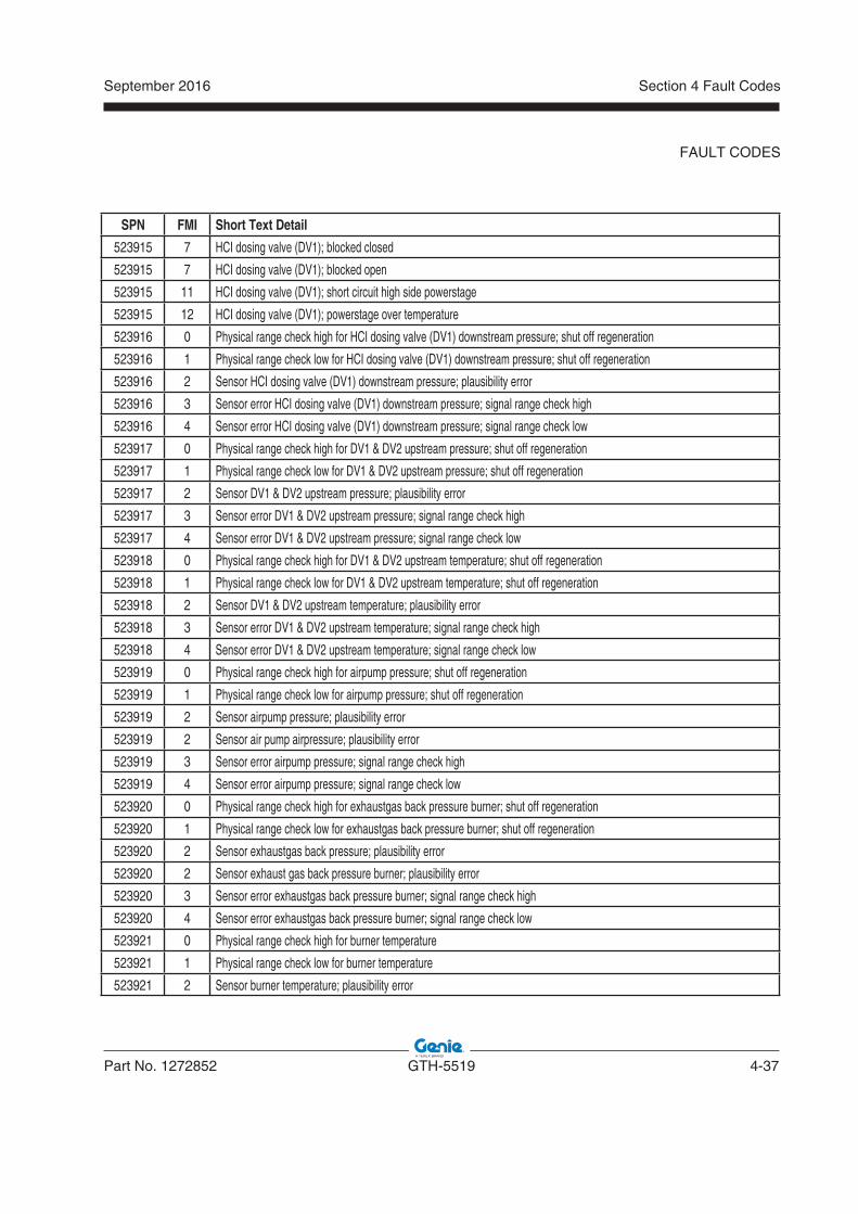
September 2016
Part No. 1272852 GTH-5519 4-37
Section 4 Fault Codes
FAULT CODES
SPN FMI Short Text Detail
523915 7 HCI dosing valve (DV1); blocked closed
523915 7 HCI dosing valve (DV1); blocked open
523915 11 HCI dosing valve (DV1); short circuit high side powerstage
523915 12 HCI dosing valve (DV1); powerstage over temperature
523916 0 Physical range check high for HCI dosing valve (DV1) downstream pressure; shut off regeneration
523916 1 Physical range check low for HCI dosing valve (DV1) downstream pressure; shut off regeneration
523916 2 Sensor HCI dosing valve (DV1) downstream pressure; plausibility error
523916 3 Sensor error HCI dosing valve (DV1) downstream pressure; signal range check high
523916 4 Sensor error HCI dosing valve (DV1) downstream pressure; signal range check low
523917 0 Physical range check high for DV1 & DV2 upstream pressure; shut off regeneration
523917 1 Physical range check low for DV1 & DV2 upstream pressure; shut off regeneration
523917 2 Sensor DV1 & DV2 upstream pressure; plausibility error
523917 3 Sensor error DV1 & DV2 upstream pressure; signal range check high
523917 4 Sensor error DV1 & DV2 upstream pressure; signal range check low
523918 0 Physical range check high for DV1 & DV2 upstream temperature; shut off regeneration
523918 1 Physical range check low for DV1 & DV2 upstream temperature; shut off regeneration
523918 2 Sensor DV1 & DV2 upstream temperature; plausibility error
523918 3 Sensor error DV1 & DV2 upstream temperature; signal range check high
523918 4 Sensor error DV1 & DV2 upstream temperature; signal range check low
523919 0 Physical range check high for airpump pressure; shut off regeneration
523919 1 Physical range check low for airpump pressure; shut off regeneration
523919 2 Sensor airpump pressure; plausibility error
523919 2 Sensor air pump airpressure; plausibility error
523919 3 Sensor error airpump pressure; signal range check high
523919 4 Sensor error airpump pressure; signal range check low
523920 0 Physical range check high for exhaustgas back pressure burner; shut off regeneration
523920 1 Physical range check low for exhaustgas back pressure burner; shut off regeneration
523920 2 Sensor exhaustgas back pressure; plausibility error
523920 2 Sensor exhaust gas back pressure burner; plausibility error
523920 3 Sensor error exhaustgas back pressure burner; signal range check high
523920 4 Sensor error exhaustgas back pressure burner; signal range check low
523921 0 Physical range check high for burner temperature
523921 1 Physical range check low for burner temperature
523921 2 Sensor burner temperature; plausibility error
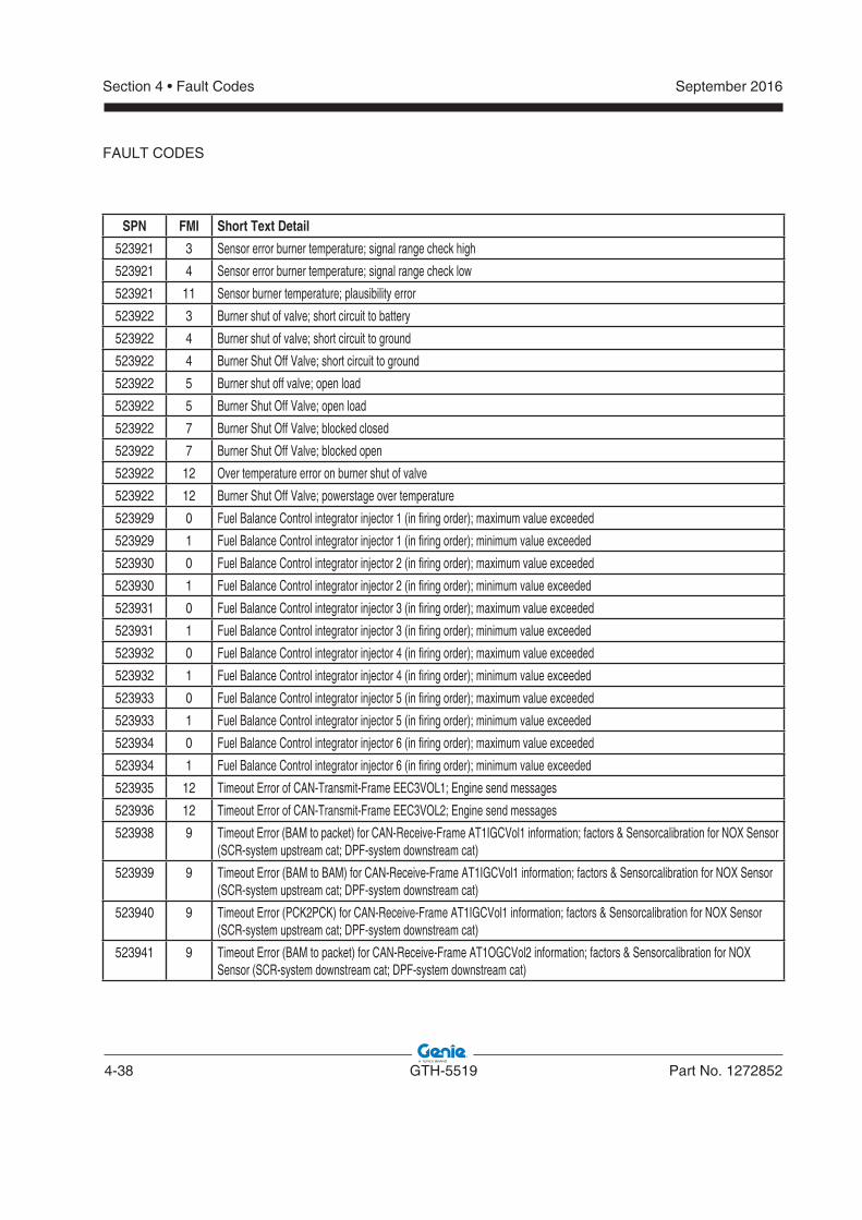
4-38 GTH-5519 Part No. 1272852
September 2016Section 4 • Fault Codes
SPN FMI Short Text Detail
523921 3 Sensor error burner temperature; signal range check high
523921 4 Sensor error burner temperature; signal range check low
523921 11 Sensor burner temperature; plausibility error
523922 3 Burner shut of valve; short circuit to battery
523922 4 Burner shut of valve; short circuit to ground
523922 4 Burner Shut Off Valve; short circuit to ground
523922 5 Burner shut off valve; open load
523922 5 Burner Shut Off Valve; open load
523922 7 Burner Shut Off Valve; blocked closed
523922 7 Burner Shut Off Valve; blocked open
523922 12 Over temperature error on burner shut of valve
523922 12 Burner Shut Off Valve; powerstage over temperature
523929 0 Fuel Balance Control integrator injector 1 (in firing order); maximum value exceeded
523929 1 Fuel Balance Control integrator injector 1 (in firing order); minimum value exceeded
523930 0 Fuel Balance Control integrator injector 2 (in firing order); maximum value exceeded
523930 1 Fuel Balance Control integrator injector 2 (in firing order); minimum value exceeded
523931 0 Fuel Balance Control integrator injector 3 (in firing order); maximum value exceeded
523931 1 Fuel Balance Control integrator injector 3 (in firing order); minimum value exceeded
523932 0 Fuel Balance Control integrator injector 4 (in firing order); maximum value exceeded
523932 1 Fuel Balance Control integrator injector 4 (in firing order); minimum value exceeded
523933 0 Fuel Balance Control integrator injector 5 (in firing order); maximum value exceeded
523933 1 Fuel Balance Control integrator injector 5 (in firing order); minimum value exceeded
523934 0 Fuel Balance Control integrator injector 6 (in firing order); maximum value exceeded
523934 1 Fuel Balance Control integrator injector 6 (in firing order); minimum value exceeded
523935 12 Timeout Error of CAN-Transmit-Frame EEC3VOL1; Engine send messages
523936 12 Timeout Error of CAN-Transmit-Frame EEC3VOL2; Engine send messages
523938 9 Timeout Error (BAM to packet) for CAN-Receive-Frame AT1IGCVol1 information; factors & Sensorcalibration for NOX Sensor (SCR-system upstream cat; DPF-system downstream cat)
523939 9 Timeout Error (BAM to BAM) for CAN-Receive-Frame AT1IGCVol1 information; factors & Sensorcalibration for NOX Sensor (SCR-system upstream cat; DPF-system downstream cat)
523940 9 Timeout Error (PCK2PCK) for CAN-Receive-Frame AT1IGCVol1 information; factors & Sensorcalibration for NOX Sensor (SCR-system upstream cat; DPF-system downstream cat)
523941 9 Timeout Error (BAM to packet) for CAN-Receive-Frame AT1OGCVol2 information; factors & Sensorcalibration for NOX Sensor (SCR-system downstream cat; DPF-system downstream cat)
FAULT CODES
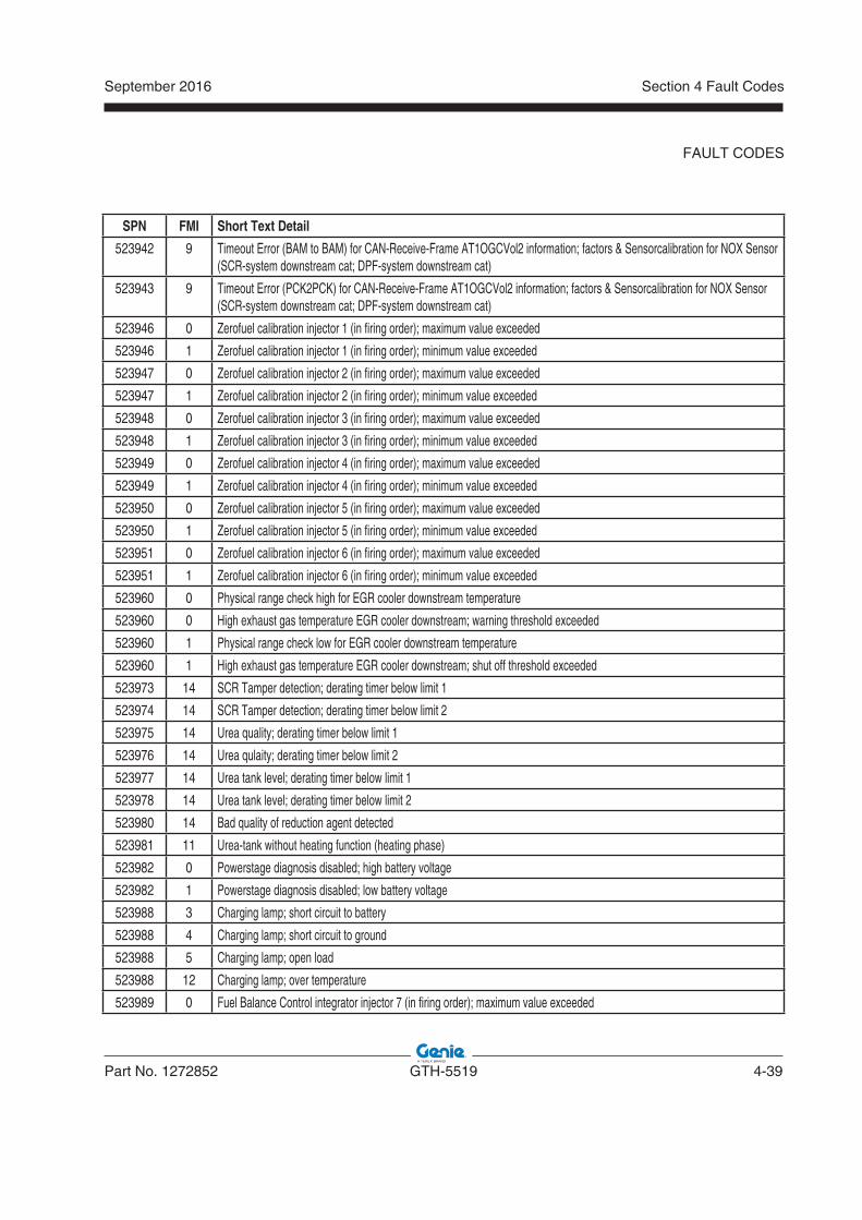
September 2016
Part No. 1272852 GTH-5519 4-39
Section 4 Fault Codes
FAULT CODES
SPN FMI Short Text Detail
523942 9 Timeout Error (BAM to BAM) for CAN-Receive-Frame AT1OGCVol2 information; factors & Sensorcalibration for NOX Sensor (SCR-system downstream cat; DPF-system downstream cat)
523943 9 Timeout Error (PCK2PCK) for CAN-Receive-Frame AT1OGCVol2 information; factors & Sensorcalibration for NOX Sensor (SCR-system downstream cat; DPF-system downstream cat)
523946 0 Zerofuel calibration injector 1 (in firing order); maximum value exceeded
523946 1 Zerofuel calibration injector 1 (in firing order); minimum value exceeded
523947 0 Zerofuel calibration injector 2 (in firing order); maximum value exceeded
523947 1 Zerofuel calibration injector 2 (in firing order); minimum value exceeded
523948 0 Zerofuel calibration injector 3 (in firing order); maximum value exceeded
523948 1 Zerofuel calibration injector 3 (in firing order); minimum value exceeded
523949 0 Zerofuel calibration injector 4 (in firing order); maximum value exceeded
523949 1 Zerofuel calibration injector 4 (in firing order); minimum value exceeded
523950 0 Zerofuel calibration injector 5 (in firing order); maximum value exceeded
523950 1 Zerofuel calibration injector 5 (in firing order); minimum value exceeded
523951 0 Zerofuel calibration injector 6 (in firing order); maximum value exceeded
523951 1 Zerofuel calibration injector 6 (in firing order); minimum value exceeded
523960 0 Physical range check high for EGR cooler downstream temperature
523960 0 High exhaust gas temperature EGR cooler downstream; warning threshold exceeded
523960 1 Physical range check low for EGR cooler downstream temperature
523960 1 High exhaust gas temperature EGR cooler downstream; shut off threshold exceeded
523973 14 SCR Tamper detection; derating timer below limit 1
523974 14 SCR Tamper detection; derating timer below limit 2
523975 14 Urea quality; derating timer below limit 1
523976 14 Urea qulaity; derating timer below limit 2
523977 14 Urea tank level; derating timer below limit 1
523978 14 Urea tank level; derating timer below limit 2
523980 14 Bad quality of reduction agent detected
523981 11 Urea-tank without heating function (heating phase)
523982 0 Powerstage diagnosis disabled; high battery voltage
523982 1 Powerstage diagnosis disabled; low battery voltage
523988 3 Charging lamp; short circuit to battery
523988 4 Charging lamp; short circuit to ground
523988 5 Charging lamp; open load
523988 12 Charging lamp; over temperature
523989 0 Fuel Balance Control integrator injector 7 (in firing order); maximum value exceeded
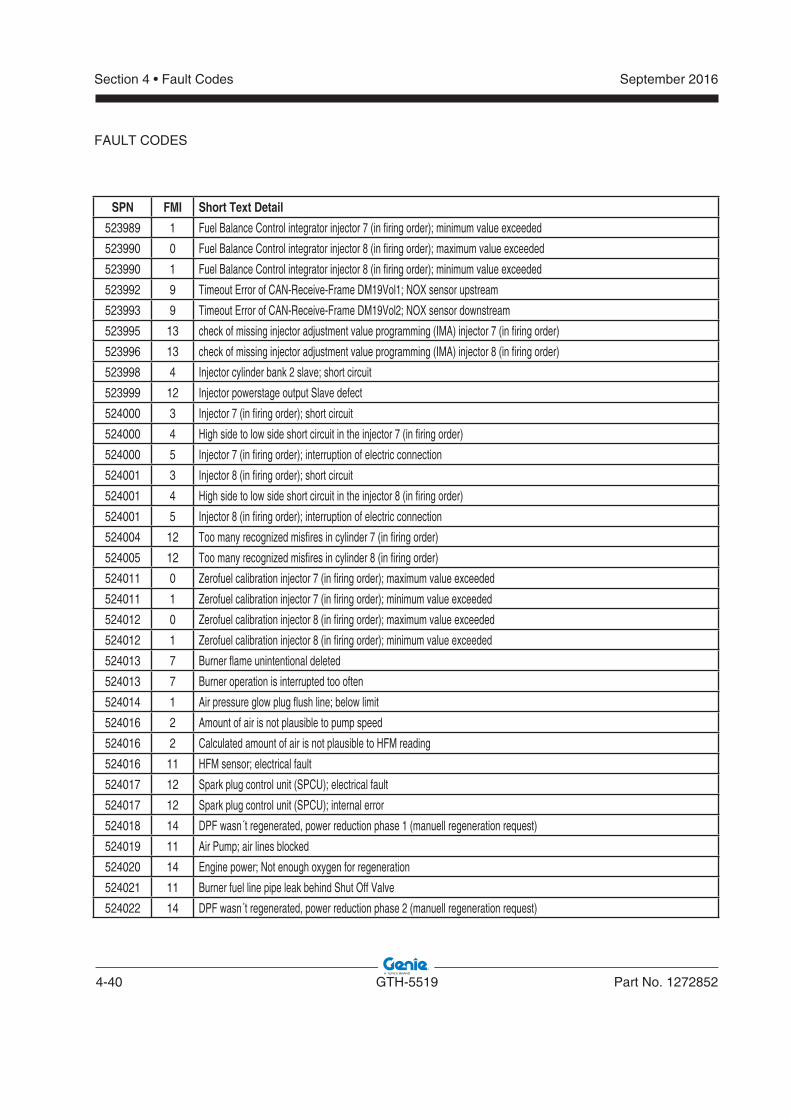
4-40 GTH-5519 Part No. 1272852
September 2016Section 4 • Fault Codes
FAULT CODES
SPN FMI Short Text Detail
523989 1 Fuel Balance Control integrator injector 7 (in firing order); minimum value exceeded
523990 0 Fuel Balance Control integrator injector 8 (in firing order); maximum value exceeded
523990 1 Fuel Balance Control integrator injector 8 (in firing order); minimum value exceeded
523992 9 Timeout Error of CAN-Receive-Frame DM19Vol1; NOX sensor upstream
523993 9 Timeout Error of CAN-Receive-Frame DM19Vol2; NOX sensor downstream
523995 13 check of missing injector adjustment value programming (IMA) injector 7 (in firing order)
523996 13 check of missing injector adjustment value programming (IMA) injector 8 (in firing order)
523998 4 Injector cylinder bank 2 slave; short circuit
523999 12 Injector powerstage output Slave defect
524000 3 Injector 7 (in firing order); short circuit
524000 4 High side to low side short circuit in the injector 7 (in firing order)
524000 5 Injector 7 (in firing order); interruption of electric connection
524001 3 Injector 8 (in firing order); short circuit
524001 4 High side to low side short circuit in the injector 8 (in firing order)
524001 5 Injector 8 (in firing order); interruption of electric connection
524004 12 Too many recognized misfires in cylinder 7 (in firing order)
524005 12 Too many recognized misfires in cylinder 8 (in firing order)
524011 0 Zerofuel calibration injector 7 (in firing order); maximum value exceeded
524011 1 Zerofuel calibration injector 7 (in firing order); minimum value exceeded
524012 0 Zerofuel calibration injector 8 (in firing order); maximum value exceeded
524012 1 Zerofuel calibration injector 8 (in firing order); minimum value exceeded
524013 7 Burner flame unintentional deleted
524013 7 Burner operation is interrupted too often
524014 1 Air pressure glow plug flush line; below limit
524016 2 Amount of air is not plausible to pump speed
524016 2 Calculated amount of air is not plausible to HFM reading
524016 11 HFM sensor; electrical fault
524017 12 Spark plug control unit (SPCU); electrical fault
524017 12 Spark plug control unit (SPCU); internal error
524018 14 DPF wasn´t regenerated, power reduction phase 1 (manuell regeneration request)
524019 11 Air Pump; air lines blocked
524020 14 Engine power; Not enough oxygen for regeneration
524021 11 Burner fuel line pipe leak behind Shut Off Valve
524022 14 DPF wasn´t regenerated, power reduction phase 2 (manuell regeneration request)
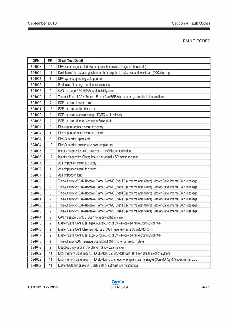
September 2016
Part No. 1272852 GTH-5519 4-41
Section 4 Fault Codes
FAULT CODES
SPN FMI Short Text Detail
524023 14 DPF wasn´t regenerated, warning condition (manuell regeneration mode)
524024 11 Deviation of the exhaust gas temperature setpoint to actual value downstream (DOC) too high
524025 5 DPF system; operating voltage error
524025 14 Particulate filter; regeneration not succesful
524028 2 CAN message PROEGRActr; plausibility error
524029 2 Timeout Error of CAN-Receive-Frame ComEGRActr -exhaust gas recirculation positioner
524030 7 EGR actuator; internal error
524031 13 EGR actuator; calibration error
524032 2 EGR actuator; status message "EGRCust" is missing
524033 7 EGR actuator; due to overload in Save Mode
524034 3 Disc separator; short circuit to battery
524034 4 Disc separator; short circuit to ground
524034 5 Disc Separator; open load
524034 12 Disc Separator; powerstage over temperature
524035 12 Injector diagnostics; time out error in the SPI communication
524036 12 Injector diagnostics Slave; time out error in the SPI communication
524037 3 Ashlamp; short circuit to battery
524037 4 Ashlamp; short circuit to ground
524037 5 Ashlamp; open load
524038 9 Timeout error of CAN-Receive-Frame ComMS_Sys1TO (error memory Slave); Master-Slave internal CAN message
524039 9 Timeout error of CAN-Receive-Frame ComMS_Sys2TO (error memory Slave); Master-Slave internal CAN message
524040 9 Timeout error of CAN-Receive-Frame ComMS_Sys3TO (error memory Slave); Master-Slave internal CAN message
524041 9 Timeout error of CAN-Receive-Frame ComMS_Sys4TO (error memory Slave); Master-Slave internal CAN message
524042 9 Timeout error of CAN-Receive-Frame ComMS_Sys5TO (error memory Slave); Master-Slave internal CAN message
524043 9 Timeout error of CAN-Receive-Frame ComMS_Sys6TO (error memory Slave); Master-Slave internal CAN message
524044 9 CAN message ComMS_Sys7 not received from slave
524045 9 Master-Slave CAN; Message-Counter-Error of CAN-Receive-Frame ComMSMoFOvR
524046 9 Master-Slave CAN; Checksum-Error of CAN-Receive-Frame ComMSMoFOvR
524047 9 Master-Slave CAN; Messsage-Length-Error of CAN-Receive-Frame ComMSMoFOvR
524048 9 Timeout error CAN message ComMSMoFOvR1TO error memory Slave
524049 9 Message copy error in the Master / Slave data transfer
524052 11 Error memory Slave reports FID MSMonFC2; Shut-Off Path test error of fuel injection system
524052 11 Error memory Slave reports FID MSMonFC3; timeout of engine state messages (ComMS_Sys1 7) from master ECU
524052 11 Master ECU and Slave ECU data sets or software are not identical
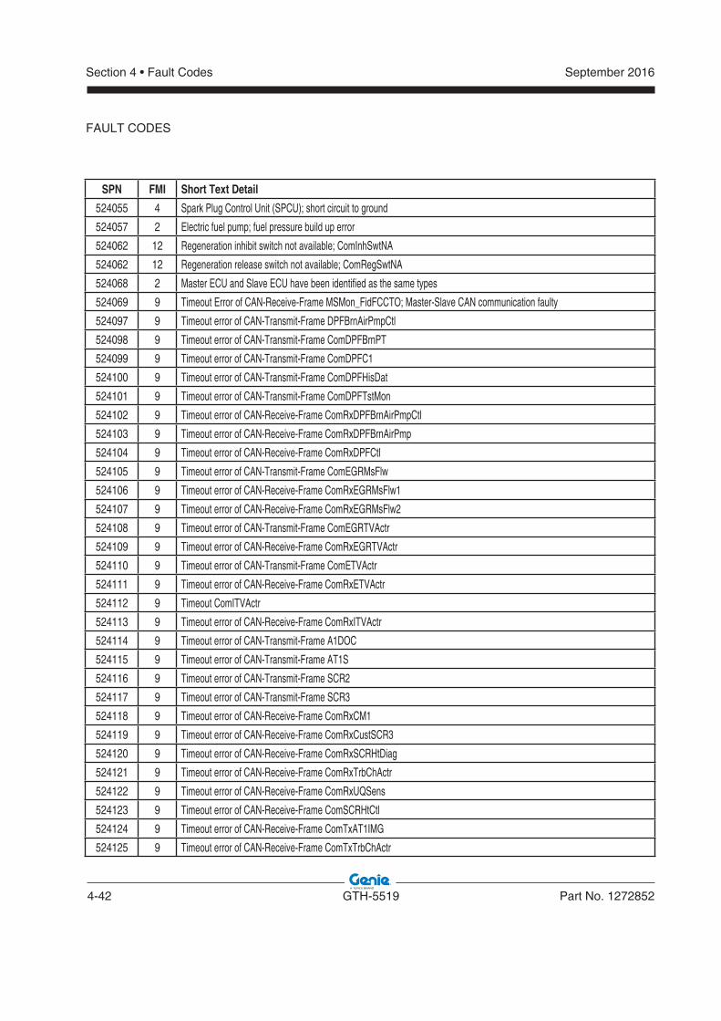
4-42 GTH-5519 Part No. 1272852
September 2016Section 4 • Fault Codes
SPN FMI Short Text Detail
524055 4 Spark Plug Control Unit (SPCU); short circuit to ground
524057 2 Electric fuel pump; fuel pressure build up error
524062 12 Regeneration inhibit switch not available; ComInhSwtNA
524062 12 Regeneration release switch not available; ComRegSwtNA
524068 2 Master ECU and Slave ECU have been identified as the same types
524069 9 Timeout Error of CAN-Receive-Frame MSMon_FidFCCTO; Master-Slave CAN communication faulty
524097 9 Timeout error of CAN-Transmit-Frame DPFBrnAirPmpCtl
524098 9 Timeout error of CAN-Transmit-Frame ComDPFBrnPT
524099 9 Timeout error of CAN-Transmit-Frame ComDPFC1
524100 9 Timeout error of CAN-Transmit-Frame ComDPFHisDat
524101 9 Timeout error of CAN-Transmit-Frame ComDPFTstMon
524102 9 Timeout error of CAN-Receive-Frame ComRxDPFBrnAirPmpCtl
524103 9 Timeout error of CAN-Receive-Frame ComRxDPFBrnAirPmp
524104 9 Timeout error of CAN-Receive-Frame ComRxDPFCtl
524105 9 Timeout error of CAN-Transmit-Frame ComEGRMsFlw
524106 9 Timeout error of CAN-Receive-Frame ComRxEGRMsFlw1
524107 9 Timeout error of CAN-Receive-Frame ComRxEGRMsFlw2
524108 9 Timeout error of CAN-Transmit-Frame ComEGRTVActr
524109 9 Timeout error of CAN-Receive-Frame ComRxEGRTVActr
524110 9 Timeout error of CAN-Transmit-Frame ComETVActr
524111 9 Timeout error of CAN-Receive-Frame ComRxETVActr
524112 9 Timeout ComITVActr
524113 9 Timeout error of CAN-Receive-Frame ComRxITVActr
524114 9 Timeout error of CAN-Transmit-Frame A1DOC
524115 9 Timeout error of CAN-Transmit-Frame AT1S
524116 9 Timeout error of CAN-Transmit-Frame SCR2
524117 9 Timeout error of CAN-Transmit-Frame SCR3
524118 9 Timeout error of CAN-Receive-Frame ComRxCM1
524119 9 Timeout error of CAN-Receive-Frame ComRxCustSCR3
524120 9 Timeout error of CAN-Receive-Frame ComRxSCRHtDiag
524121 9 Timeout error of CAN-Receive-Frame ComRxTrbChActr
524122 9 Timeout error of CAN-Receive-Frame ComRxUQSens
524123 9 Timeout error of CAN-Receive-Frame ComSCRHtCtl
524124 9 Timeout error of CAN-Receive-Frame ComTxAT1IMG
524125 9 Timeout error of CAN-Receive-Frame ComTxTrbChActr
FAULT CODES
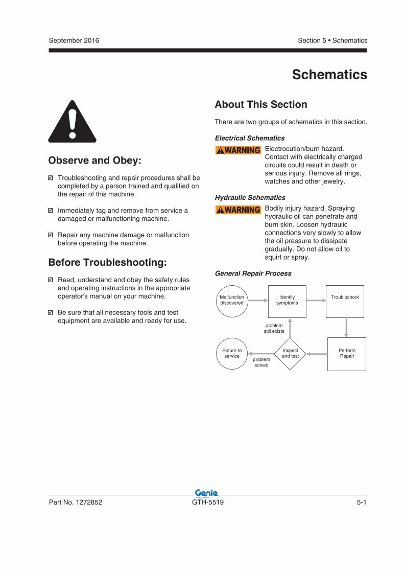
September 2016
Part No. 1272852 GTH-5519 5-1
Section 5 • Schematics
Schematics
Observe and Obey:
Troubleshooting and repair procedures shall be completed by a person trained and qualified on the repair of this machine.
Immediately tag and remove from service a damaged or malfunctioning machine.
Repair any machine damage or malfunction before operating the machine.
Before Troubleshooting:
Read, understand and obey the safety rules and operating instructions in the appropriate operator's manual on your machine.
Be sure that all necessary tools and test equipment are available and ready for use.
About This Section
There are two groups of schematics in this section.
Electrical Schematics
WARNING Electrocution/burn hazard. Contact with electrically charged circuits could result in death or serious injury. Remove all rings, watches and other jewelry.
Hydraulic Schematics
WARNING Bodily injury hazard. Sprayinghydraulic oil can penetrate andburn skin. Loosen hydraulicconnections very slowly to allowthe oil pressure to dissipategradually. Do not allow oil to squirt or spray.
General Repair Process
Malfunctiondiscovered
Identifysymptoms
Troubleshoot
PerformRepair
Inspectand test
Return toservice
problemstill exists
problemsolved
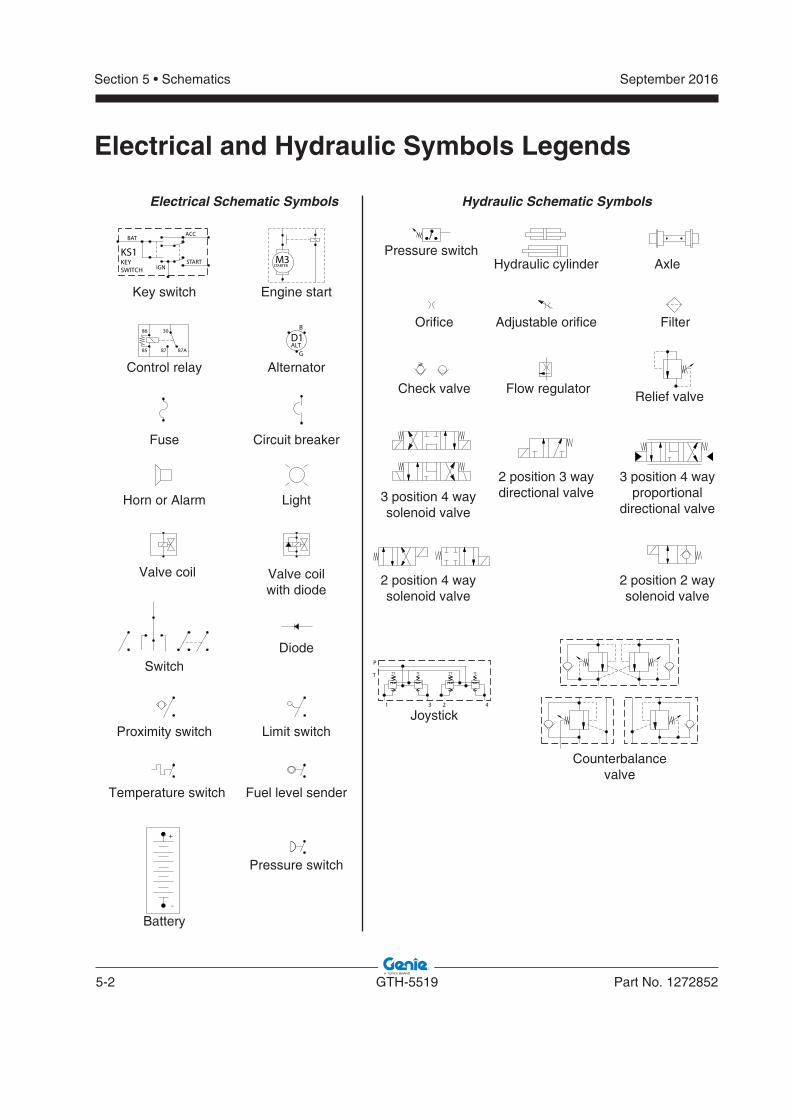
5-2 GTH-5519 Part No. 1272852
September 2016Section 5 • Schematics
Electrical and Hydraulic Symbols Legends
87A85
86 30
87
-
+
B
G
D1ALT
M3STARTER
KS1KEYSWITCH
BATACC
STARTIGN
1 3 2 4
T
P
Electrical Schematic Symbols Hydraulic Schematic Symbols
Engine start
Pressure switch
Orifice
Check valve Flow regulatorRelief valve
3 position 4 wayproportional
directional valve
2 position 3 waydirectional valve3 position 4 way
solenoid valve
2 position 4 waysolenoid valve
2 position 2 waysolenoid valve
Counterbalancevalve
Joystick
Adjustable orifice Filter
Hydraulic cylinder Axle
Key switch
Control relay Alternator
Circuit breakerFuse
Horn or Alarm Light
Valve coilwith diode
Valve coil
SwitchDiode
Limit switchProximity switch
Temperature switch Fuel level sender
Pressure switch
Battery
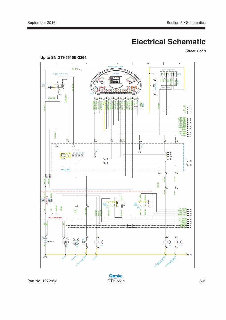
September 2016
Part No. 1272852 GTH-5519 5-3
Section 5 • Schematics
Electrical Schematic Sheet 1 of 8
°C
GENIE
!!
31
a Terex brand
GENIEENGINE RPM
hour
°C
60
105
33 a
18
10
22
11
17 7
16 b
14
15
cdef g h
12
13
2420
Up to SN GTH5515B-2364
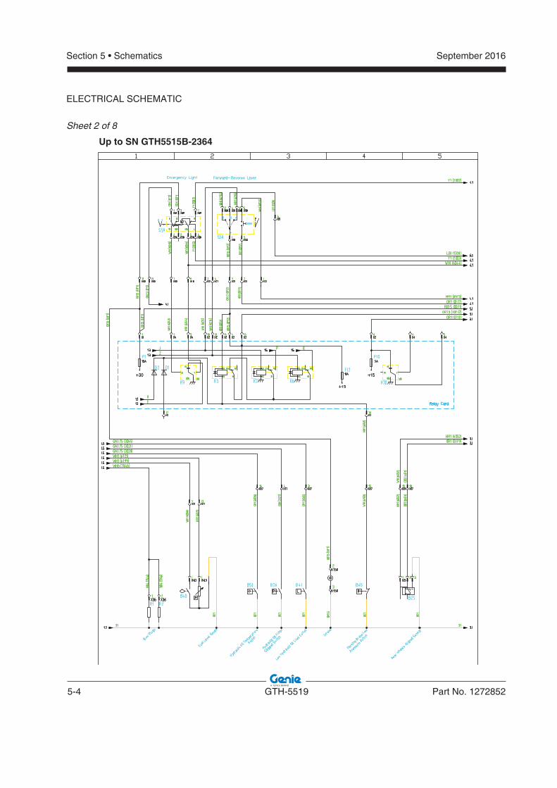
5-4 GTH-5519 Part No. 1272852
September 2016Section 5 • Schematics
ELECTRICAL SCHEMATIC
Sheet 2 of 8
Up to SN GTH5515B-2364
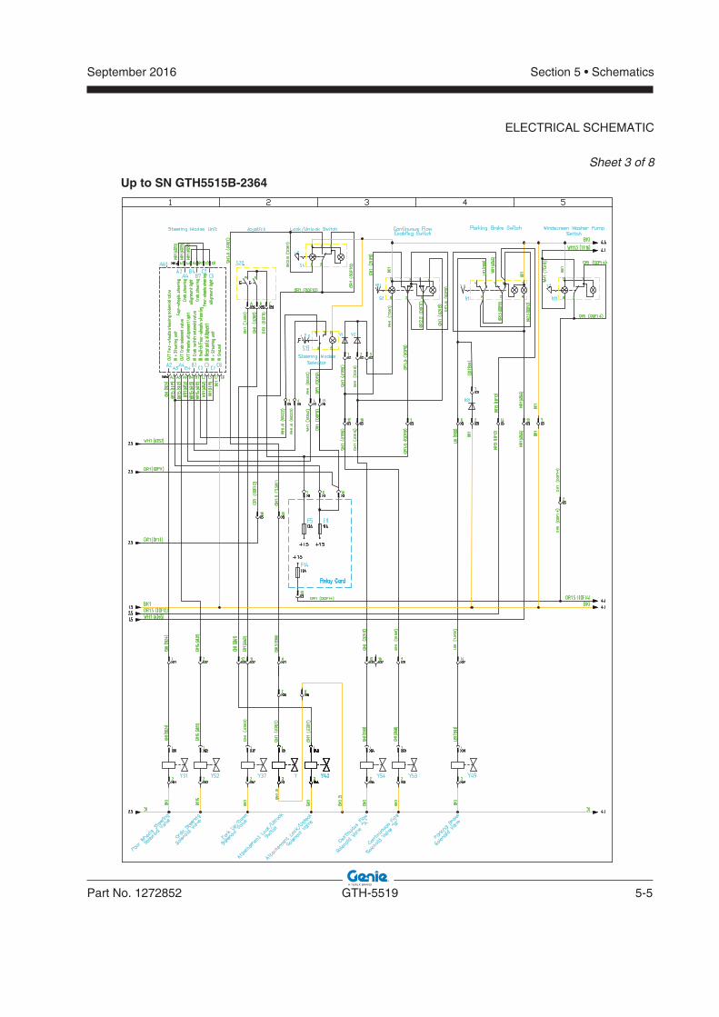
September 2016
Part No. 1272852 GTH-5519 5-5
Section 5 • Schematics
ELECTRICAL SCHEMATIC
Sheet 3 of 8
Up to SN GTH5515B-2364
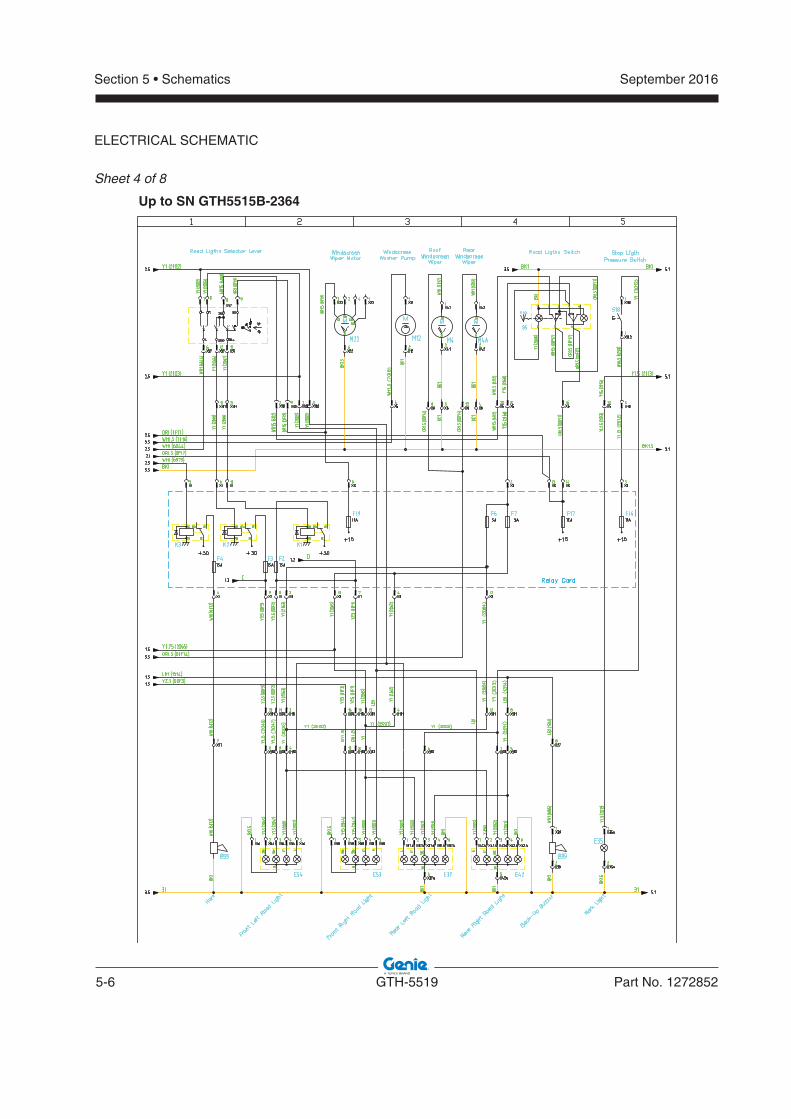
5-6 GTH-5519 Part No. 1272852
September 2016Section 5 • Schematics
ELECTRICAL SCHEMATIC
Sheet 4 of 8
Up to SN GTH5515B-2364
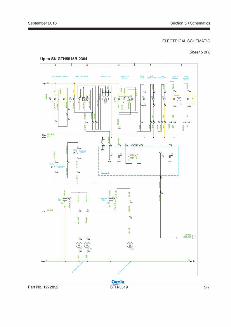
September 2016
Part No. 1272852 GTH-5519 5-7
Section 5 • Schematics
ELECTRICAL SCHEMATIC
Sheet 5 of 8
Up to SN GTH5515B-2364
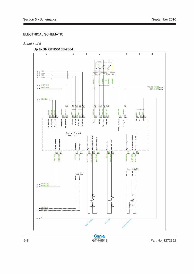
5-8 GTH-5519 Part No. 1272852
September 2016Section 5 • Schematics
ELECTRICAL SCHEMATIC
Sheet 6 of 8
Up to SN GTH5515B-2364
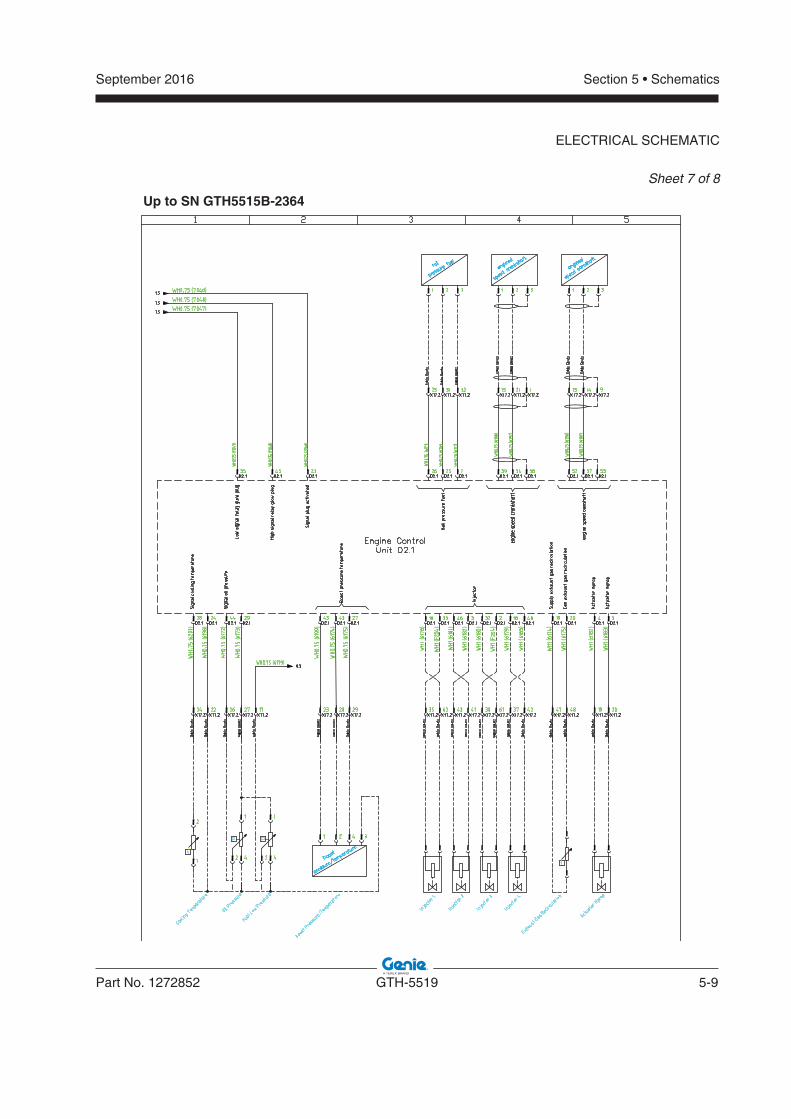
September 2016
Part No. 1272852 GTH-5519 5-9
Section 5 • Schematics
ELECTRICAL SCHEMATIC
Sheet 7 of 8
Up to SN GTH5515B-2364
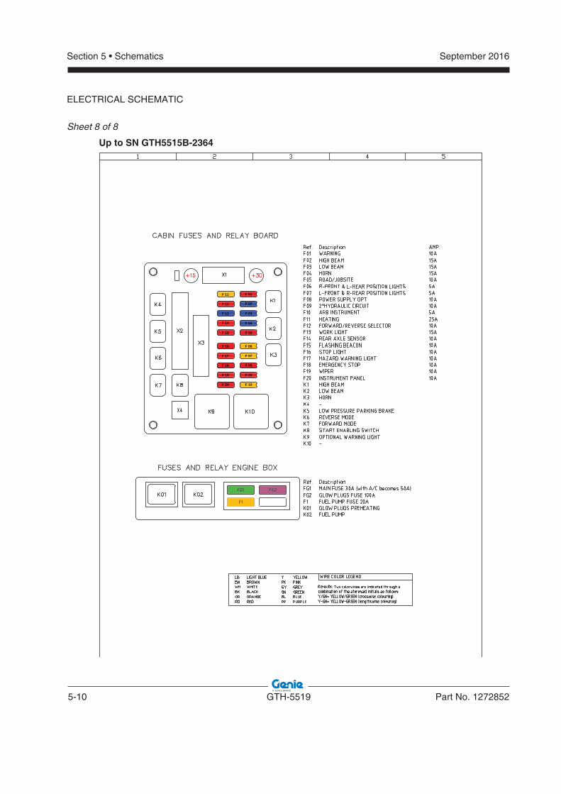
5-10 GTH-5519 Part No. 1272852
September 2016Section 5 • Schematics
ELECTRICAL SCHEMATIC
Sheet 8 of 8
F 10
F 09
F 08
F 07
F 06
F 05
F 04
F 03
F 02
F 01
F 20
F 19
F 18
F 17
F 16
F 15
F 14
F 13
F 12
F 11
Up to SN GTH5515B-2364
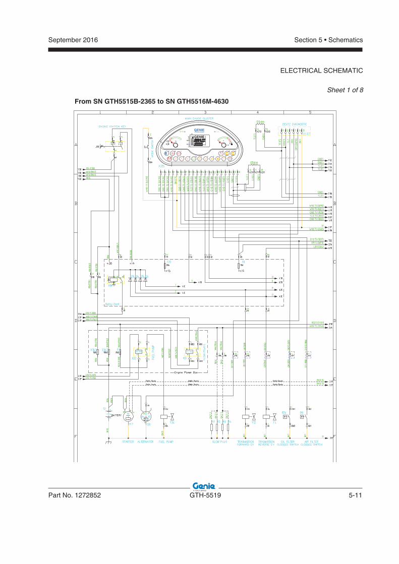
September 2016
Part No. 1272852 GTH-5519 5-11
Section 5 • Schematics
Sheet 1 of 8
From SN GTH5515B-2365 to SN GTH5516M-4630
ELECTRICAL SCHEMATIC
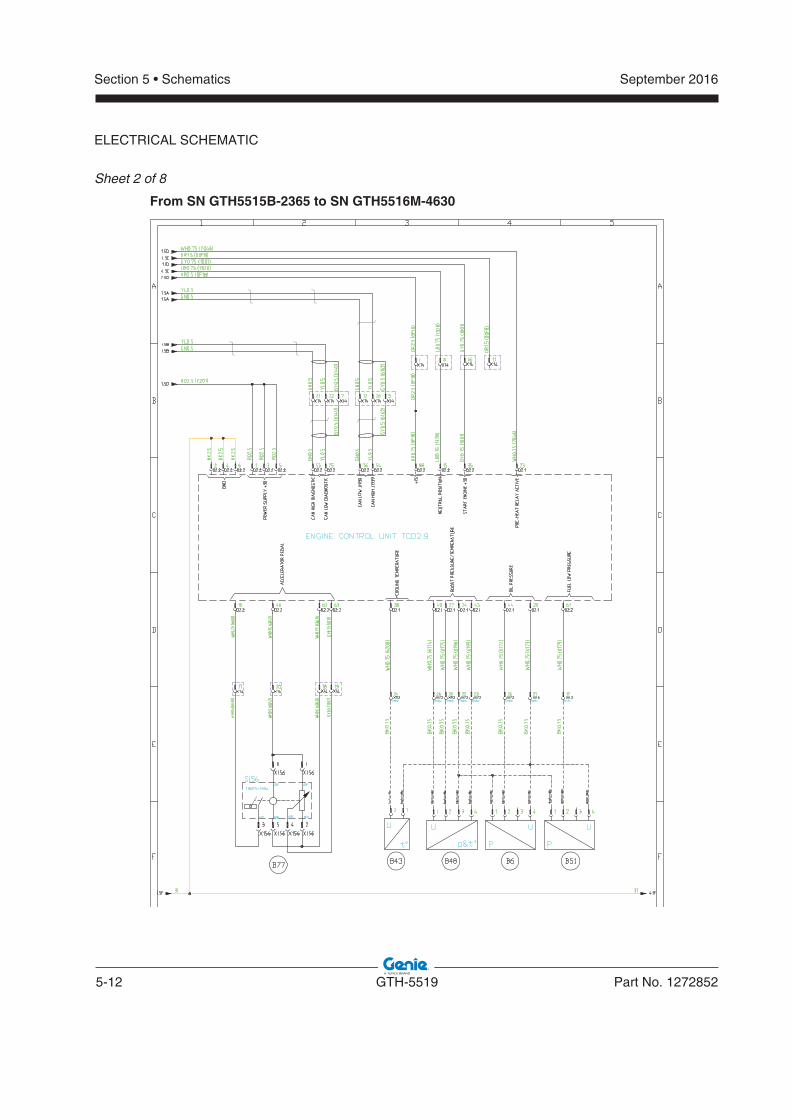
5-12 GTH-5519 Part No. 1272852
September 2016Section 5 • Schematics
ELECTRICAL SCHEMATIC
Sheet 2 of 8
From SN GTH5515B-2365 to SN GTH5516M-4630
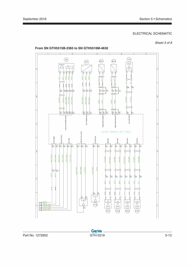
September 2016
Part No. 1272852 GTH-5519 5-13
Section 5 • Schematics
ELECTRICAL SCHEMATIC
Sheet 3 of 8
From SN GTH5515B-2365 to SN GTH5516M-4630
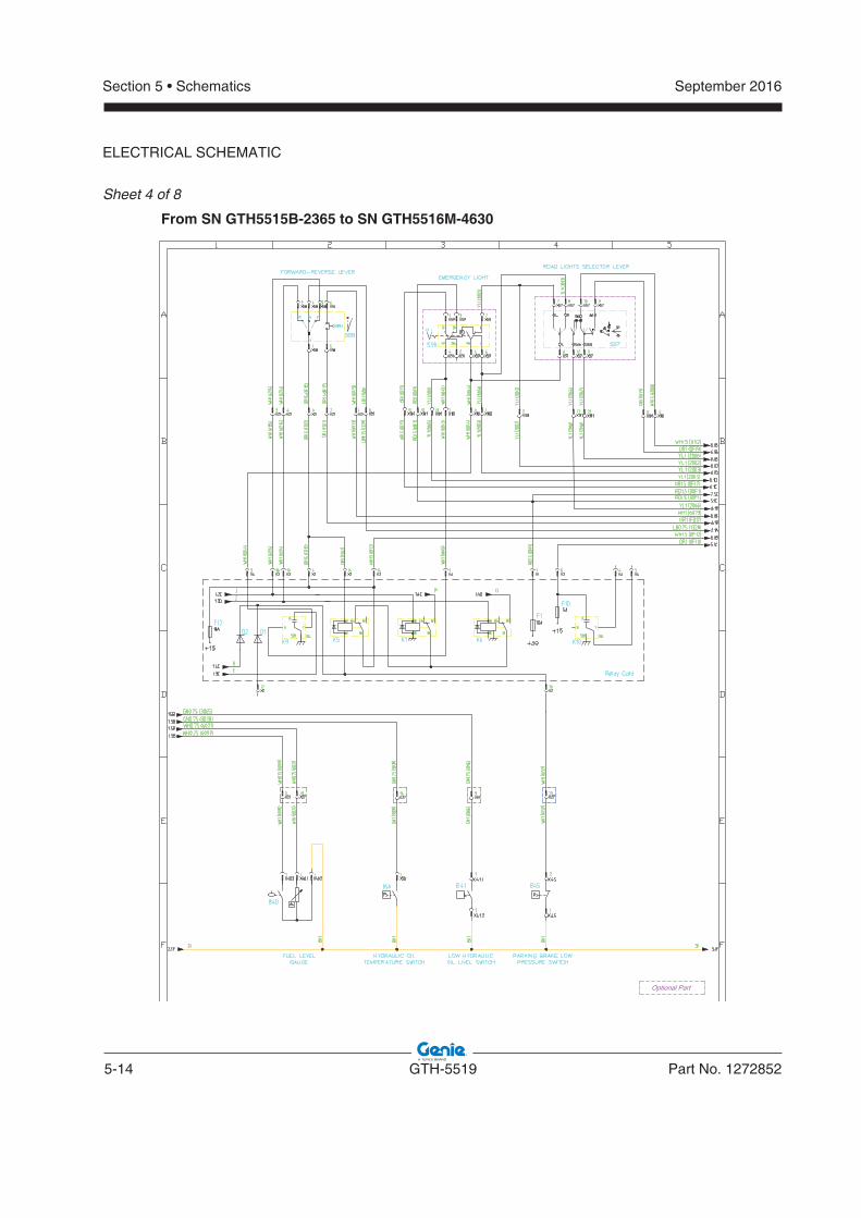
5-14 GTH-5519 Part No. 1272852
September 2016Section 5 • Schematics
ELECTRICAL SCHEMATIC
Sheet 4 of 8
From SN GTH5515B-2365 to SN GTH5516M-4630
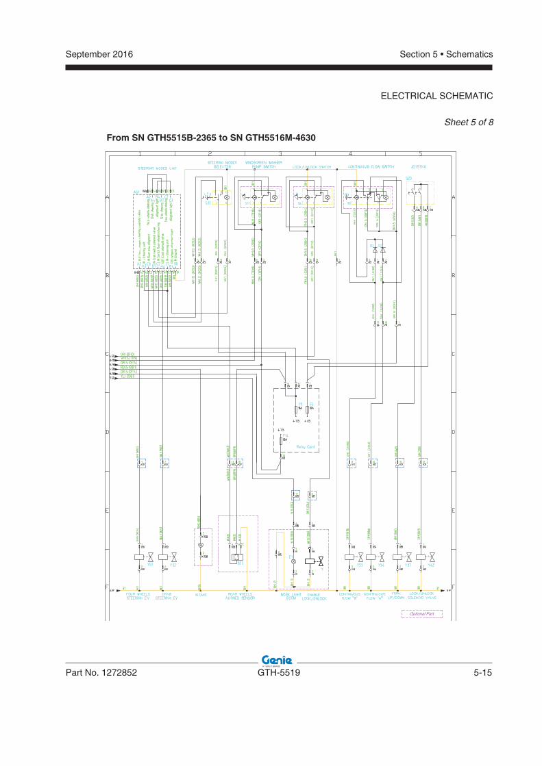
September 2016
Part No. 1272852 GTH-5519 5-15
Section 5 • Schematics
ELECTRICAL SCHEMATIC
Sheet 5 of 8
From SN GTH5515B-2365 to SN GTH5516M-4630
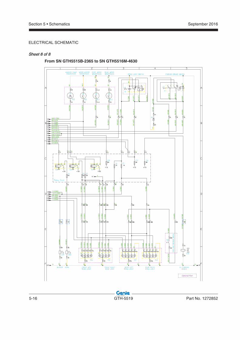
5-16 GTH-5519 Part No. 1272852
September 2016Section 5 • Schematics
ELECTRICAL SCHEMATIC
Sheet 8 of 8Sheet 6 of 8
From SN GTH5515B-2365 to SN GTH5516M-4630
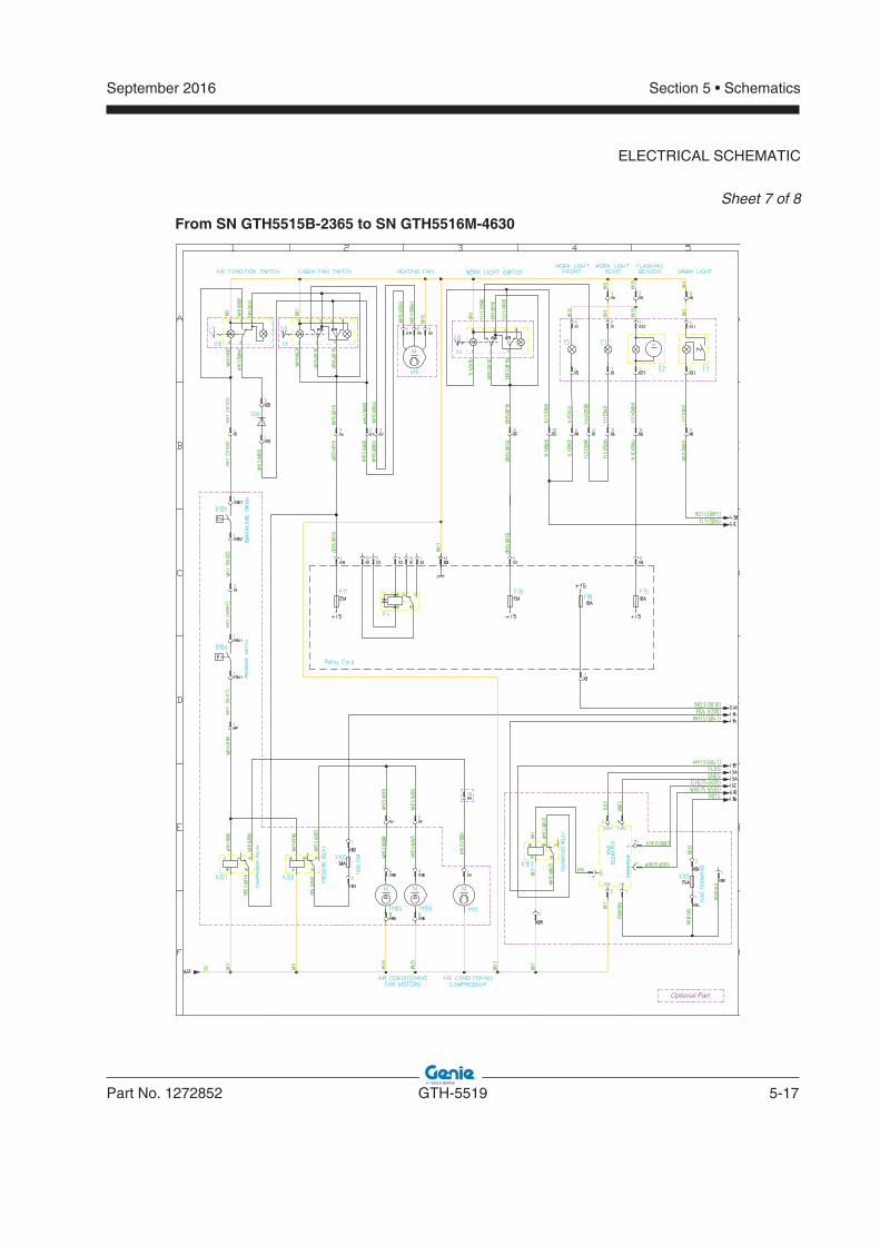
September 2016
Part No. 1272852 GTH-5519 5-17
Section 5 • Schematics
ELECTRICAL SCHEMATIC
Sheet 7 of 8
From SN GTH5515B-2365 to SN GTH5516M-4630
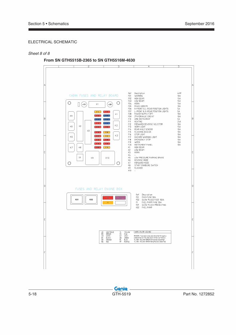
5-18 GTH-5519 Part No. 1272852
September 2016Section 5 • Schematics
ELECTRICAL SCHEMATIC
Sheet 8 of 8
From SN GTH5515B-2365 to SN GTH5516M-4630
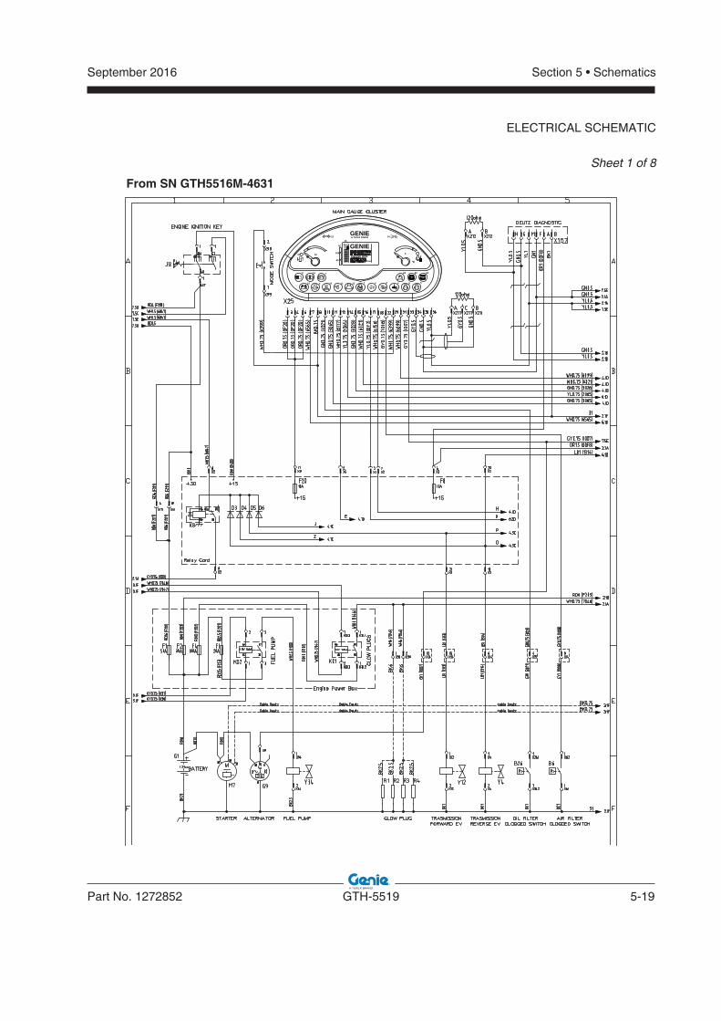
September 2016
Part No. 1272852 GTH-5519 5-19
Section 5 • Schematics
ELECTRICAL SCHEMATIC
Sheet 1 of 8
From SN GTH5516M-4631
°C
GENIE
!!
31
a Terex brand
GENIEENGINE RPM
hour
°C
60
105
33 a
18
10
22
11
17 7
16 b
14
15
cdef g h
12
13
2420
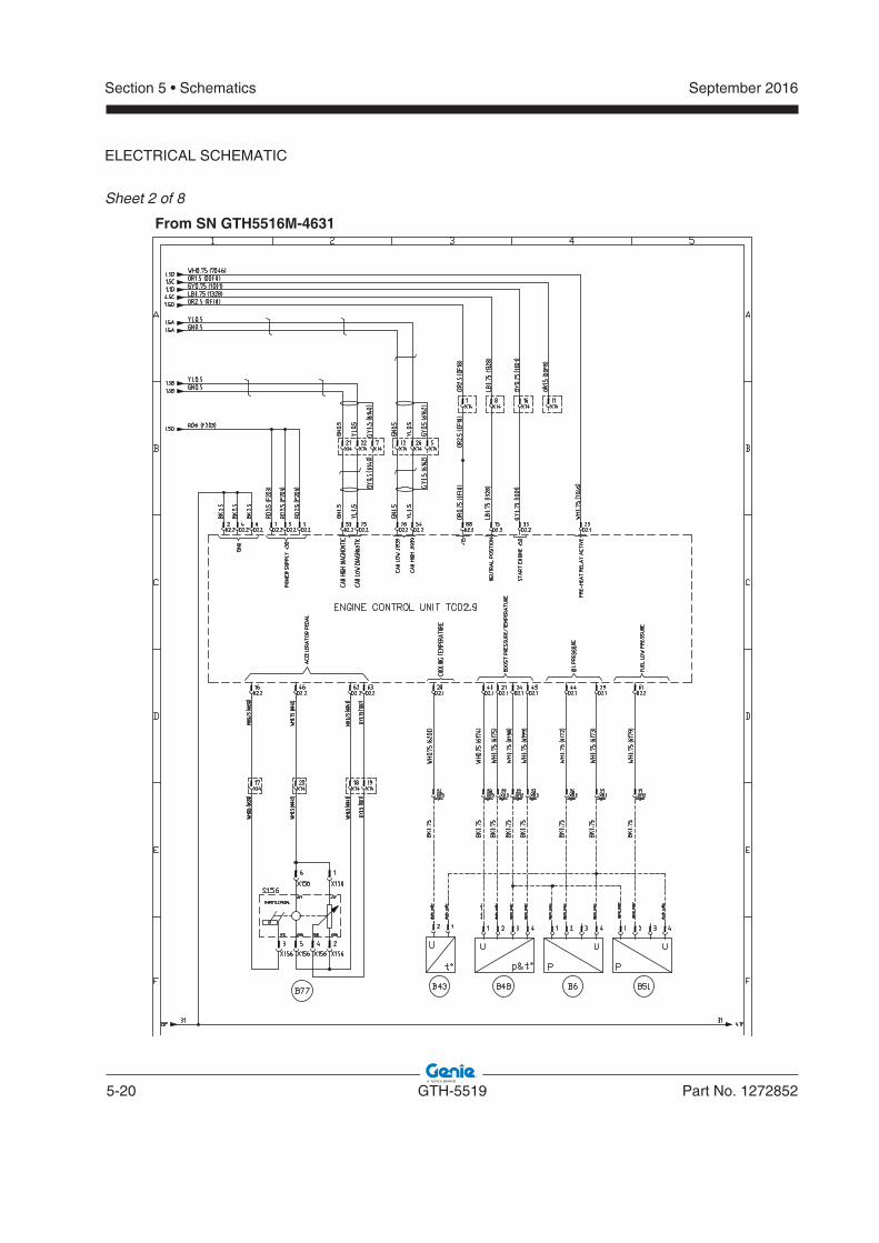
5-20 GTH-5519 Part No. 1272852
September 2016Section 5 • Schematics
ELECTRICAL SCHEMATIC
Sheet 2 of 8
From SN GTH5516M-4631
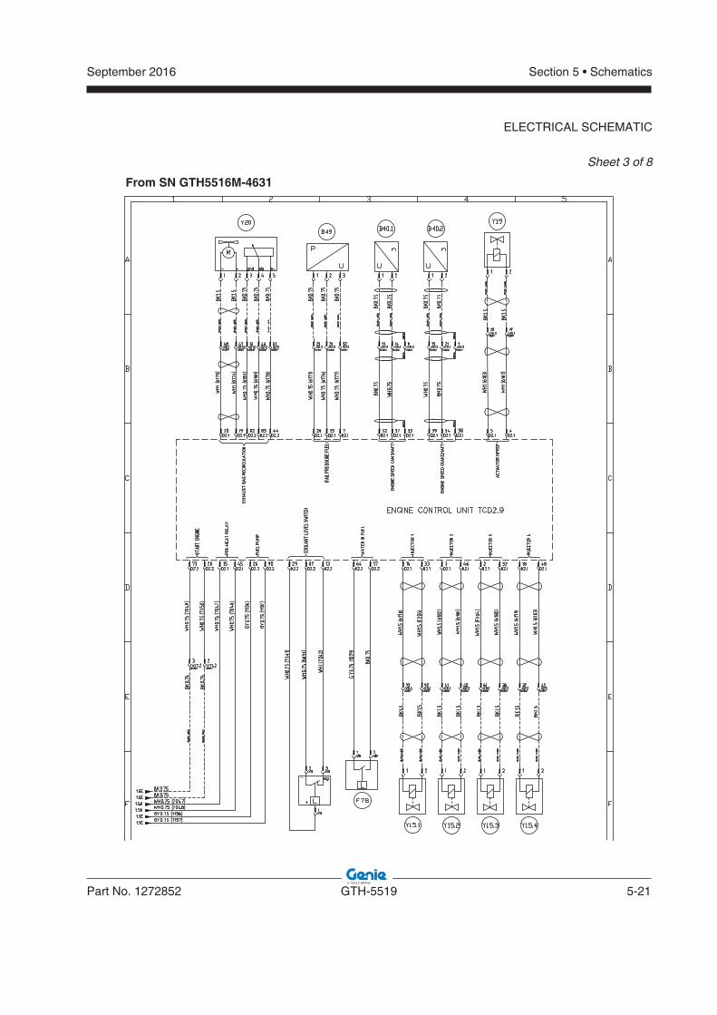
September 2016
Part No. 1272852 GTH-5519 5-21
Section 5 • Schematics
ELECTRICAL SCHEMATIC
Sheet 3 of 8
From SN GTH5516M-4631
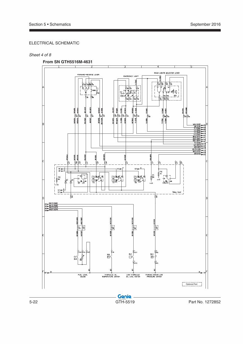
5-22 GTH-5519 Part No. 1272852
September 2016Section 5 • Schematics
ELECTRICAL SCHEMATIC
Sheet 4 of 8
Optional Part
From SN GTH5516M-4631
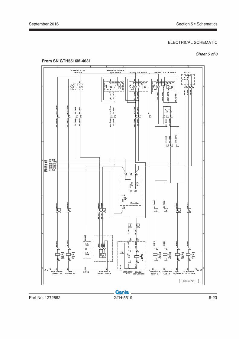
September 2016
Part No. 1272852 GTH-5519 5-23
Section 5 • Schematics
ELECTRICAL SCHEMATIC
Sheet 5 of 8
Optional Part
From SN GTH5516M-4631
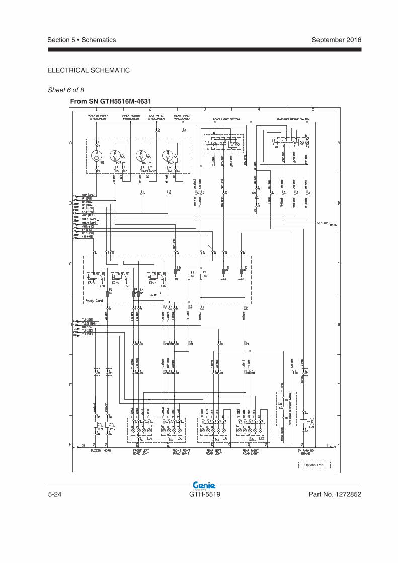
5-24 GTH-5519 Part No. 1272852
September 2016Section 5 • Schematics
ELECTRICAL SCHEMATIC
Sheet 6 of 8
Optional Part
From SN GTH5516M-4631
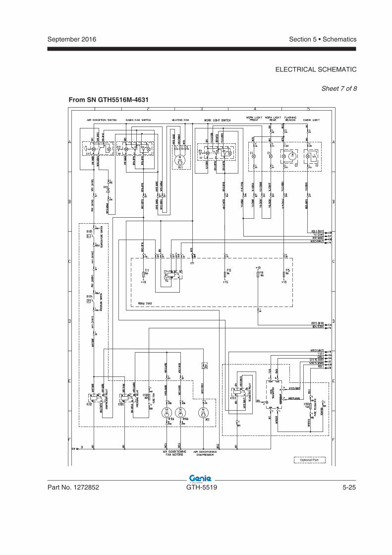
September 2016
Part No. 1272852 GTH-5519 5-25
Section 5 • Schematics
ELECTRICAL SCHEMATIC
Sheet 7 of 8
Optional Part
From SN GTH5516M-4631
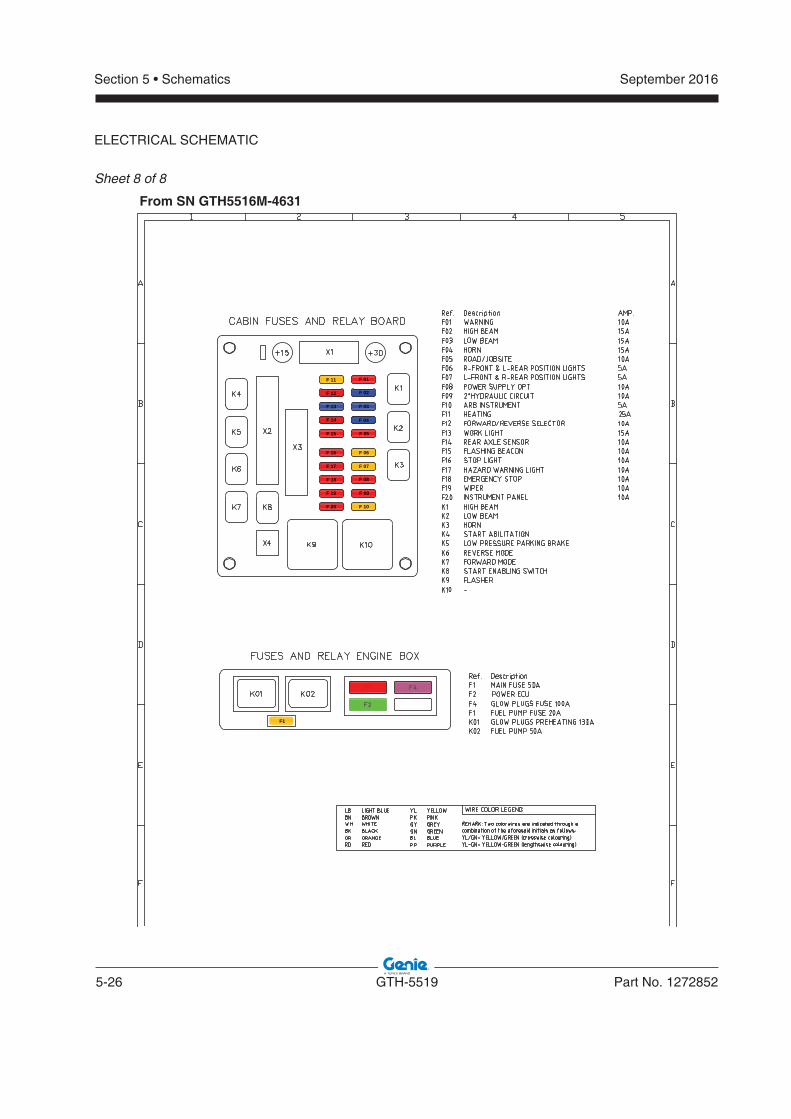
5-26 GTH-5519 Part No. 1272852
September 2016Section 5 • Schematics
ELECTRICAL SCHEMATIC
Sheet 8 of 8
F 10
F 09
F 08
F 07
F 06
F 05
F 04
F 03
F 02
F 01
F 20
F 19
F 18
F 17
F 16
F 15
F 14
F 13
F 12
F 11
F1
From SN GTH5516M-4631
September 2016Section 5 • Schematics
5-27 5-28
Hydraulic Schematic
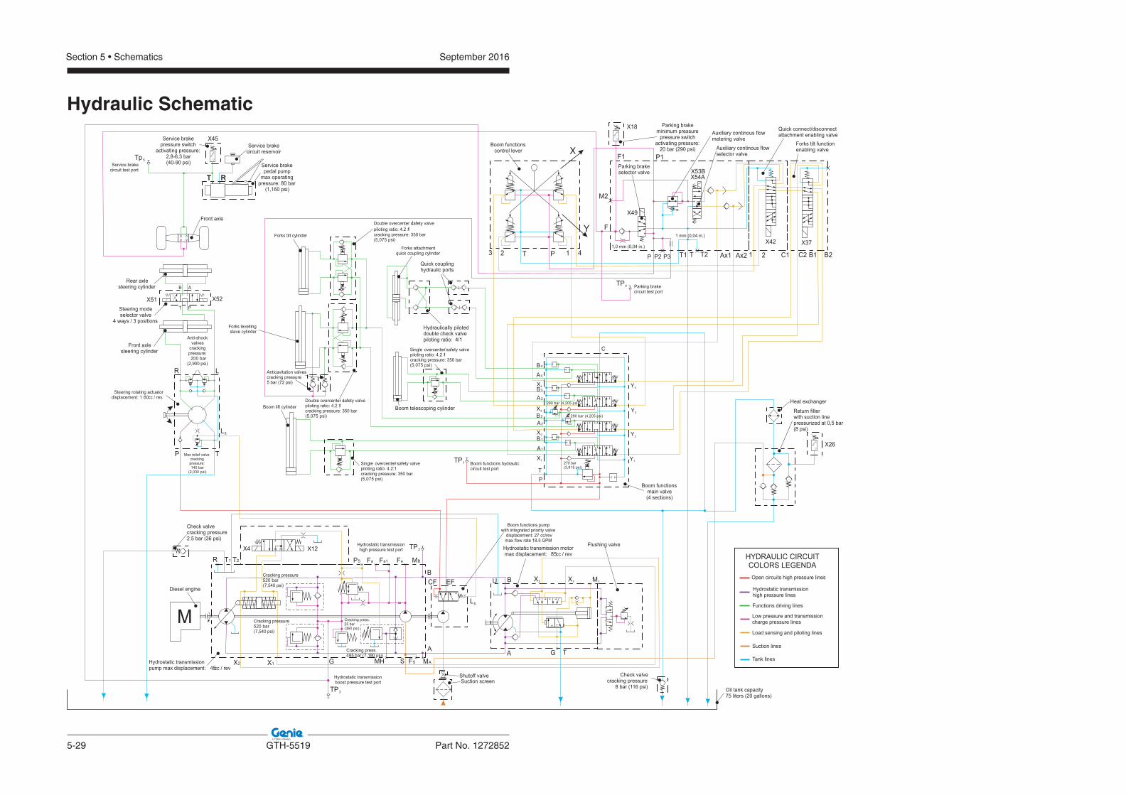
5-29 GTH-5519 Part No. 1272852
September 2016Section 5 • Schematics
Hydraulic Schematic
M
X1X2 G MH S
A A
M1X1X2
TG
T1 PS Fa Fa1 Fe MBT2R
BBU
MAFS
CF EF
LS
LS
LR
TP
P 1 423 T TP P2 P3
F
P1
M2
F1
T1 1 2T2 B1C1 C2 B2Ax2Ax1
X
Y
A1
X1
X2
X3
X4
B1
B3
A3
B2
A2
A4
B4
TP
C
Y1
Y2
Y3
Y4
T R
Diesel engine
Hydrostatic transmissionpump max displacement: cc / rev45
Hydrostatic transmission motormax displacement: cc / rev85
Flushing valve
Boom functions pumpwith integrated priority valve
displacement: 27 cc/revmax flow rate 18.5 GPM
Suction screen
Heat exchanger
Anticavitation valvescracking pressure5 bar (72 psi)
Check valvecracking pressure2.5 bar (36 psi)
Check valvecracking pressure
8 bar (116 psi) Oil tank capacity75 liters (20 gallons)
Boom functionscontrol lever
Boom functionsmain valve(4 sections)
HYDRAULIC CIRCUITCOLORS LEGENDA
Functions driving lines
Low pressure and transmissioncharge pressure lines
Hydrostatic transmissionhigh pressure lines
Load sensing and piloting lines
Open circuits high pressure lines
Suction lines
Tank lines
Steering rotating actuatordisplacement: 1 cc / rev.60
Front axle
Service brakecircuit reservoir
Service brakepedal pump
max operatingpressure: 80 bar
(1 160 psi),
Forks levellingslave cylinder
Forks tilt cylinder
Boom telescoping cylinderBoom lift cylinder
Double overcenter safety valve/piloting ratio: 4.2 1/cracking pressure: 350 bar
, )isp 570 5(
Double overcenter safety valve/piloting ratio: 4.2 1/cracking pressure: 350 bar
, )isp 570 5(
Single /overcenter safety valvepiloting ratio: 4.2 1/cracking pressure: 350 bar
, )isp 570 5(
Single /overcenter safety valvepiloting ratio: 4.2:1cracking pressure: 350 bar
, )isp 570 5(
270 bar, )isp 519 3(
, )isp 502 4( rab 092
, )isp 502 4( rab 092
Cracking pressure25 rab 0
( psi)7,540
Cracking pressure25 rab 0
( psi)7,540
Cracking press.25 bar
0 )isp63(
Cracking press.4 bar ( psi)95 7,180
Max relief valvecrackingpressure:
4 rab 01030, )isp2(
Anti-shockvalves
crackingpressure:
00 rab2( psi)2,900
Quick couplinghydraulic ports
Forks attachmentquick coupling cylinder
Steering modeselector valve
4 ways / 3 positions
Front axlesteering cylinder
Rear axlesteering cylinder
TP3
Tp 5
TP2
TP1
Hydraulically piloteddouble check valvepiloting ratio: 4/1
T
A
P
B
Shutoff valve
Parking brakeminimum pressure
pressure switchactivating pressure:
20 bar (290 psi)
Parking brakeselector valve
Auxiliary continous flowmetering valve
1,0 mm (0,04 in.)
1 mm (0,04 in.)
Auxiliary continous flowselector valve
Forks tilt functionenabling valve
Quick connect/disconnectattachment enabling valveService brake
pressure switchactivating pressure:
2,8-6,3 bar(40-90 psi)
Hydrostatic transmissionboost pressure test port
Hydrostatic transmissionhigh pressure test port
Boom functions hydrauliccircuit test port
Service brakecircuit test port
X4
X51
X37X42
X52
X12
Return filterwith suction linepressurized at 0,5 bar(8 psi)
X45
X18
X49
X53BX54A
X26
TP4 Parking brakecircuit test port
:yB detubirtsi
Dwww.genielift.com
California Proposition 65
WARNING Operating, servicing and maintaining this equipment, passenger vehicle or off-highway motor vehicle can expose you to chemicals including engine exhaust, carbon monoxide, phthalates, and lead, which are known to the State of California to cause cancer and birth defects or other reproductive harm. These chemicals can be emitted from or contained in other various parts and systems, fluids and some component wear by-products. To minimize exposure, avoid breathing exhaust, do not idle the engine except as necessary, service your equipment and vehicle in a well-ventilated area and wear gloves or wash your hands frequently when servicing your equipment or vehicle and after operation. For more information go towww.P65Warnings.ca.gov/passenger-vehicle.
Breathing diesel engine exhaust exposes you to chemicals known to the State of California to cause cancer and birth defects or other reproductive harm.• a ni enigne eht etarepo dna trats syawlAwell-ventilated area.• If in an enclosed area, vent the exhaust to the outside.• Do not modify or tamper with the exhaust system.• Do not idle the engine except as necessary.For more information go to www.P65warnings.ca.gov/diesel.