Embed Size (px)
Citation preview

Service and Repair Manual
Serial Number Range
Z®-135/70 from Z13505-101 to Z13513-2000
This manual includes: Repair procedures Fault Codes Electrical and Hydraulic Schematics
For detailed maintenance procedures, refer to the appropriate Maintenance Manual for your machine.
Part No. 1268557GT Rev A3 March 2018

Service and Repair Manual March 2018
Introduction
ii Z®-135/70 Part No. 1268557GT
Intr oducti on Intr oducti on
Important Read, understand and obey the safety rules and operating instructions in the appropriate Operator's Manual on your machine before attempting any procedure.
This manual provides troubleshooting and repair procedures for qualified service professionals.
Basic mechanical, hydraulic and electrical skills are required to perform most procedures. However, several procedures require specialized skills, tools, lifting equipment and a suitable workshop. In these instances, we strongly recommend that maintenance and repair be performed at an authorized Genie dealer service center.
Compliance
Machine Classification Group B/Type 3 as defined by ISO 16368
Machine Design Life Unrestricted with proper operation, inspection and scheduled maintenance.
Technical Publications Genie has endeavored to deliver the highest degree of accuracy possible. However, continuous improvement of our products is a Genie policy. Therefore, product specifications are subject to change without notice.
Readers are encouraged to notify Genie of errors and send in suggestions for improvement. All communications will be carefully considered for future printings of this and all other manuals.
Contact Us: Internet: www.genielift.com E-mail: [email protected]
Find a Manual for this Model Go to http://www.genielift.com
Use the links to locate Service Manuals, Maintenance Manuals, Service and Repair Manuals, Parts Manuals and Operator's Manuals.
Copyright © 2015 by Terex Corporation
1268557 Rev A, September 2015
First Edition, First Printing
Genie is a registered trademark of Terex South Dakota, Inc. in the U.S.A. and many other countries.
“Z” is a trademark of Terex South Dakota, Inc.

March 2018 Service and Repair Manual
Introduction
Part No. 1268557GT Z®-135/70 iii
Revision History Revision Date Section Procedure / Page / Description A 9/2015 Initial Release
A1 11/2015 Schematics Wire Color Legend
A2 6/2016 Specifications Performance Specifications
Repair Procedures 4-9, 6-1
A3 3/2018 Repair Display Module
Reference Examples: Electronic Version
Click on any content or procedure in the Table of Contents to view the update.
Section – Repair Procedure, 4-2
Section – Fault Codes, All charts
Section – Schematics, Legends and schematics

Service and Repair Manual March 2018
Introduction
iv Z®-135/70 Part No. 1268557GT
Serial Number Legend
1 Model 2 Model year 3 Sequence number 4 Serial label (located under cover) 5 Serial number (stamped on chassis)
March 2018 Service and Repair Manual
Safety Rules
Part No. 1268557GT Z®-135/70 v
Section 1 Safety R ules
Danger Failure to obey the instructions and safety rules in this manual and the appropriate Operator's Manual on your machine will result in death or serious injury.
Many of the hazards identified in the operator's manual are also safety hazards when maintenance and repair procedures are performed.
Do Not Perform Maintenance Unless: You are trained and qualified to perform
maintenance on this machine.
You read, understand and obey:
• manufacturer's instructions and safety rules
• employer's safety rules and worksite regulations
• applicable governmental regulations
You have the appropriate tools, lifting equipment and a suitable workshop.
Service and Repair Manual March 2018
Safety Rules
vi Z®-135/70 Part No. 1268557GT
Personal Safety Any person working on or around a machine must be aware of all known safety hazards. Personal safety and the continued safe operation of the machine should be your top priority.
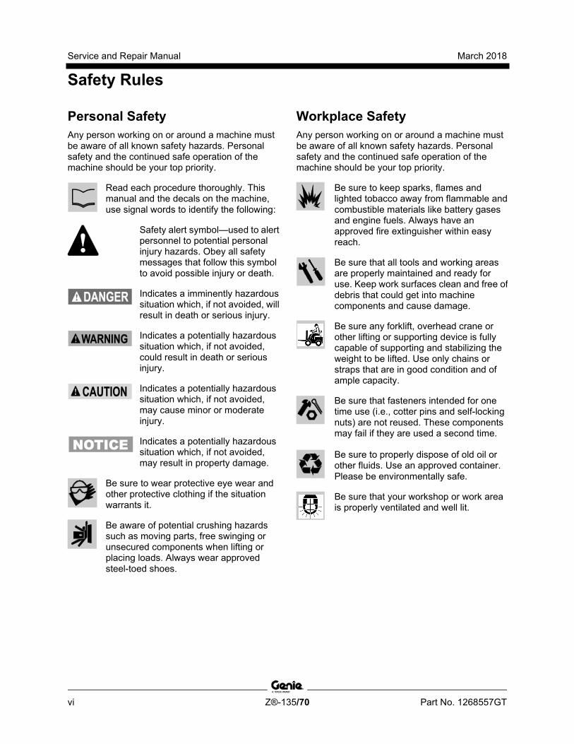
Read each procedure thoroughly. This manual and the decals on the machine, use signal words to identify the following:
Safety alert symbol—used to alert personnel to potential personal injury hazards. Obey all safety messages that follow this symbol to avoid possible injury or death.
Indicates a imminently hazardous situation which, if not avoided, will result in death or serious injury.
Indicates a potentially hazardous situation which, if not avoided, could result in death or serious injury.
Indicates a potentially hazardous situation which, if not avoided, may cause minor or moderate injury.
Indicates a potentially hazardous situation which, if not avoided, may result in property damage.
Be sure to wear protective eye wear and other protective clothing if the situation warrants it.
Be aware of potential crushing hazards such as moving parts, free swinging or unsecured components when lifting or placing loads. Always wear approved steel-toed shoes.
Workplace Safety Any person working on or around a machine must be aware of all known safety hazards. Personal safety and the continued safe operation of the machine should be your top priority.
Be sure to keep sparks, flames and lighted tobacco away from flammable and combustible materials like battery gases and engine fuels. Always have an approved fire extinguisher within easy reach.
Be sure that all tools and working areas are properly maintained and ready for use. Keep work surfaces clean and free of debris that could get into machine components and cause damage.
Be sure any forklift, overhead crane or other lifting or supporting device is fully capable of supporting and stabilizing the weight to be lifted. Use only chains or straps that are in good condition and of ample capacity.
Be sure that fasteners intended for one time use (i.e., cotter pins and self-locking nuts) are not reused. These components may fail if they are used a second time.
Be sure to properly dispose of old oil or other fluids. Use an approved container. Please be environmentally safe.
Be sure that your workshop or work area is properly ventilated and well lit.
March 2018
Table of Contents
Part No. 1268557GT Z®-135/70 vii
Introduction Introduction ........................................................................................................... ii Important Information ............................................................................................. ii
Find a Manual for this Model .................................................................................. ii
Serial Number Legend .......................................................................................... iv
Section 1 Safety Rules .......................................................................................................... v General Safety Rules ............................................................................................. v
Section 2 Specifications ....................................................................................................... 1 Machine Specifications ........................................................................................... 1
Performance Specifications .................................................................................... 1
Hydraulic Specification ........................................................................................... 2
Hydraulic Component Specifications...................................................................... 5
Deutz BF4L 2011 Engine Specifications ................................................................ 7
Deutz TD2011L04i Engine Specifications .............................................................. 9
Cummins B4.5L Engine Specifications ................................................................ 11
Cummins B3.3T Engine Specifications ................................................................ 13
Perkins 1104C-44 Engine Specifications ............................................................. 15
Perkins 804D-33T Engine Specifications ............................................................. 17
Machine Torque Specifications ............................................................................ 19
Hydraulic Hose and Fitting Torque Specifications ............................................... 20
Torque Procedure ................................................................................................ 21
SAE and Metric Fasteners Torque Charts ........................................................... 23
March 2018
Table of Contents
viii Z®-135/70 Part No. 1268557GT
Section 3 Repair Procedures ............................................................................................. 24 Introduction .......................................................................................................... 24
Platform Controls ............................................................................................... 26 Platform Controls ................................................................................................. 26
1-1 Platform Circuit Board .................................................................................... 27
How to Remove the LED Circuit Board .......................................................... 28
1-2 Membrane Decal ........................................................................................... 29
1-3 Joysticks - How to Calibrate a Joystick ......................................................... 30
How to Reset a Proportional Valve Coil Default ............................................. 34
How to Set the Function Thresholds and Default Functions Speeds ............. 34
How to Adjust the Function Speeds ............................................................... 36
How to Adjust the Function Ramp Rate Setting ............................................. 37
Platform Components ....................................................................................... 39 2-1 Platform Leveling Cylinder ............................................................................. 39
2-2 Platform Rotator ............................................................................................. 40
How to Bleed the Platform Rotator ................................................................. 41
2-3 Platform Level Sensor - How to Calibrate the Platform Level Sensor ........... 42
2-4 Platform Overload System (if equipped) ........................................................ 43
Jib Boom Components ...................................................................................... 46 3-1 Jib Boom Cable Track ................................................................................... 47
How to Repair the Cable Track....................................................................... 49
3-2 Jib Boom ........................................................................................................ 50
3-3 Jib Boom Lift Cylinder .................................................................................... 52
3-4 Jib Boom Level Cylinder ................................................................................ 53
3-5 Jib Boom Extension Cylinder ......................................................................... 54
3-6 Jib Boom Bellcrank Angle Sensor ................................................................. 56
How to Calibrate the Jib Boom Bellcrank Angle Sensor ................................ 58
March 2018
Table of Contents
Part No. 1268557GT Z®-135/70 ix
Boom Components ............................................................................................ 64 4-1 Primary Boom Cable Track ............................................................................ 65
How to Repair the Primary Boom Cable Track ............................................... 67
4-2 Secondary Boom Cable Track ....................................................................... 68
How to Repair the Secondary Boom Cable Track .......................................... 70
4-3 Primary Boom................................................................................................. 71
4-4 Primary Boom Lift Cylinder ............................................................................ 73
4-5 Secondary Boom Lift Cylinder ........................................................................ 74
4-6 Primary Boom Extension Cylinder ................................................................. 78
4-7 Secondary Boom Extension Cylinders ........................................................... 79
4-8 Primary Boom Angle Sensor .......................................................................... 81
How to Calibrate the Primary Boom Angle Sensor ......................................... 82
4-9 Secondary Boom Angle Sensor ..................................................................... 88
How to Calibrate the Secondary Boom Angle Sensor .................................... 89
Engines ................................................................................................................ 95 5-1 RPM Adjustment ............................................................................................ 95
5-2 Flex Plate ....................................................................................................... 95
How to install a Type "A" Flex Plate ................................................................ 96
How to install a Type "B" Flex Plate ................................................................ 98
Ground Controls ................................................................................................. 99 6-1 Bypass/Recovery Key Switch ........................................................................ 99
How to Use the Recovery Mode ................................................................... 101
6-2 Circuit Boards ............................................................................................... 102
6-3 Membrane Decal .......................................................................................... 104
6-4 Full Machine Calibration ............................................................................... 105
Display Module ................................................................................................. 106
March 2018
Table of Contents
x Z®-135/70 Part No. 1268557GT
Hydraulic Pumps .............................................................................................. 115 7-1 Function Pump ............................................................................................. 115
How to Prime the Function Pump ................................................................. 116
How to Adjust the Function Pump Standby Pressure................................... 116
How to Adjust the Function Pump Pressure Compensator .......................... 117
7-2 Drive Pump .................................................................................................. 118
How to Prime the Drive Pump ...................................................................... 119
Manifolds .......................................................................................................... 120 8-1 Function Manifold - (before serial number 440) ........................................... 120
8-2 Function Manifold - (after serial number 439) .............................................. 124
8-3 Valve Adjustments - Function Manifold ....................................................... 128
How to Adjust the System Relief Valve ........................................................ 128
How to Adjust the Primary Boom Extend Relief Valve ................................. 129
8-4 Platform Manifold ......................................................................................... 131
8-5 Jib Boom Manifold ....................................................................................... 132
8-6 Flow Control Mainfold .................................................................................. 134
8-7 Function Enable Valve ................................................................................. 135
8-8 Turntable Rotation Manifold ......................................................................... 136
8-9 Steer and Axle Manifold ............................................................................... 138
8-10 Valve Adjustments - Steer and Axle Manifold ........................................... 142
8-11 Traction Manifold ....................................................................................... 144
8-12 Valve Adjustments - Traction Manifold ...................................................... 148
8-13 Drive Oil Diverter Manifold (welder option) ................................................ 149
8-14 Valve Coils ................................................................................................. 150
Turntable Rotation Components .................................................................... 152 9-1 Turntable Rotation Assembly ....................................................................... 152
How to Adjust the Turntable Rotation Gear Backlash .................................. 153
9-2 Turntable Level Sensor - How to Calibrate the Turntable Level Sensor ..... 154

March 2018
Table of Contents
Part No. 1268557GT Z®-135/70 xi
Axle Components ............................................................................................. 158 10-1 Steer Sensors ............................................................................................ 158
How to Calibrate a Replacement Steer Sensor ............................................ 160
How to Calibrate All Steer Sensors ............................................................... 161
10-2 Steer Cylinders ........................................................................................... 163
10-3 Axle Extension Cylinders ........................................................................... 164
10-4 Axle Angle Sensors .................................................................................... 165
How to Calibrate the Axle Angle Sensors ..................................................... 167
Section 4 Fault Codes ....................................................................................................... 171 Introduction ......................................................................................................... 171
Control System Fault Codes .............................................................................. 172
Fault Matrix ......................................................................................................... 189
March 2018
Table of Contents
xii Z®-135/70 Part No. 1268557GT
Section 5 Schematics ....................................................................................................... 191 Introduction ........................................................................................................ 191
Wire Circuit Legend ........................................................................................... 192
Wire Color Legend ............................................................................................. 196
Limit Switches and Angle Sensors..................................................................... 201
Circuit Connector Legend .................................................................................. 205
Drive Chassis and Platform Controller Pin Legend ........................................... 208
Safety Controller Pin Legend ............................................................................. 209
Turntable Controller Pin Legend ........................................................................ 210
Engine Relay and Fuse Panel Legend - Deutz BF4L 2011, TD2011L04i, Perkins 1104C-44 and 804D-33T ........................................................................... 211
Engine Relay and Fuse Panel Legend - Cummins B4.5L and B3.3T ................ 212
Electrical Symbols Legend ................................................................................. 213
Hydraulic Symbols Legend ................................................................................ 214
Perkins 1104C-44 and 804D-33T Engine Electrical Schematic ........................ 216
Cummins B4.5L and B3-3.3T Engine Electrical Schematic ............................... 217
Generator Wiring Schematic .............................................................................. 220
Hydraulic Generator (Welder Option) ................................................................ 221
Hydraulic Schematic (before serial number 180, except for serial number 102)224
Hydraulic Schematic (serial number 102 and from serial number 180 to 534).. 225
Hydraulic Schematic (from serial number 535) .................................................. 227
Electrical Schematic ........................................................................................... 229

March 2018 Service and Repair Manual
Part No. 1268557GT Z®-135/70 13
This page intentionally left blank.


March 2018 Service and Repair Manual
Specifications
Part No. 1268557GT Z®-135/70 1
Section 2 Specificati ons
Machine Specifications Tires and wheels
Tire size 445/65D22.5, FF Tire ply rating 18
Tire weight, new foam-filled (minimum)
815 lbs 370 kg
Overall tire diameter 46.5 in 118.1 cm
Wheel diameter 22.5 in 57.2 cm
Wheel width 13 in 33 cm
Wheel lugs 10 @ 3/4 -16
Lug nut torque, dry 420 ft-lbs 569.4 Nm
Lug nut torque, lubricated 320 ft-lbs 433.9 Nm
Fluid capacities
Fuel tank 40 gallons 151.4 liters
Hydraulic tank 65 gallons 246 liters
Hydraulic system (including tank) 123 gallons 466 liters
Drive hubs 47 fl oz 1390 cc
Turntable rotation drive hub 40 fl oz 1183 cc
Drive hub oil type: SAE 90 multipurpose hypoid gear oil API service classification GL5
Performance Specifications Drive speed, maximum Stowed position, high speed 2.8 mph
4.5 km/h 40 ft / 9.7 sec
12.2 m / 9.7 sec
Raised or extended 0.7 mph 1.1 km/h
40 ft / 40 sec 12.2 m / 40 sec
Primary and Secondary booms raised, and Primary and Jib extended
0.4 mph 0.6 km/h
40 ft / 68.5 sec 12.2 m / 68.5 sec
Braking distance, maximum High range on paved surface 3 to 6 ft
1 to 2 m
Gradeability See Operator's Manual
Boom function speeds, maximum from platform controls Jib boom up/down 38 to 43 seconds Jib boom extend/retract 38 to 42 seconds Primary boom up/down -60° to +70°
110 to 125 seconds
Primary boom extend/retract 35 to 48 seconds
Secondary boom up/down 80 to 95 seconds Secondary boom extend/retract 88 to 98 seconds Turntable rotate, 360° fully stowed
88 to 92 seconds
Turntable rotate, 360°jib or primary booms extended
160 to 180 seconds
Turntable rotate, 360°jib and primary booms extended
280 to 350 seconds
For operational specifications, refer to the Operator's Manual.
Continuous improvement of our products is a Genie policy. Product specifications are subject to change without notice or obligation.

Service and Repair Manual March 2018
Specifications
2 Z®-135/70 Part No. 1268557GT
Hydraulic Oil Specifications Hydraulic Fluid Specifications Genie specifications require hydraulic oils which are designed to give maximum protection to hydraulic systems, have the ability to perform over a wide temperature range, and the viscosity index should exceed 140. They should provide excellent antiwear, oxidation prevention, corrosion inhibition, seal conditioning, and foam and aeration suppression properties.
Cleanliness level, minimum
ISO 15/13
Water content, maximum
250 ppm
Recommended Hydraulic Fluid
Hydraulic oil type Chevron Rando HD Premium Viscosity grade 32 Viscosity index 200
Optional Hydraulic Fluids
Mineral based Shell Tellus S2 V 32 Shell Tellus S2 V 46
Shell Tellus S4 VX 32 Shell Shell Donax TG (Dexron III)
Chevron 5606A Biodegradable Petro Canada Environ MV 46 Fire resistant UCON Hydrolube HP-5046
Note: Genie specifications require additional equipment and special installation instructions for the approved optional fluids. Consult Genie Product Support before use.
Optional fluids may not have the same hydraulic lifespan and may result in component damage.
Note: Extended machine operation can cause the hydraulic fluid temperature to increase beyond it's maximum allowable range. If the hydraulic fluid temperature consistently exceeds 200°F / 90°C an optional oil cooler may be required.
Do not top off with incompatible hydraulic fluids. Hydraulic fluids may be incompatible due to the differences in base additive chemistry. When incompatible fluids are mixed, insoluble materials may form and deposit in the hydraulic system, plugging hydraulic lines, filters, control valves and may result in component damage.
Note: Do not operate the machine when the ambient air temperature is consistently above 120°F / 49°C.
Hydraulic Fluid Temperature Range
Ambient air temperature
1 Chevron hydraulic oil 5606A 2 Petro-Canada Environ MV 46 3 UCON Hydrolube HP-5046D 4 Chevron Rando HD premium oil MV
March 2018 Service and Repair Manual
Specifications
Part No. 1268557GT Z®-135/70 3
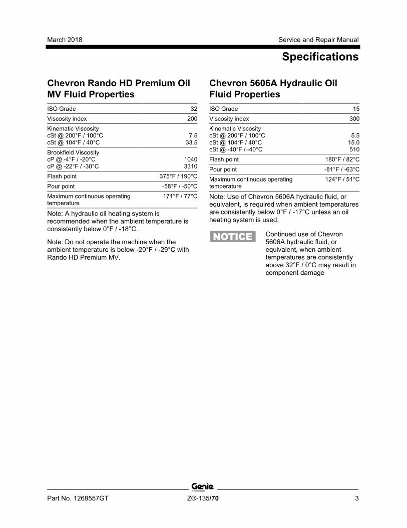
Chevron Rando HD Premium Oil MV Fluid Properties ISO Grade 32 Viscosity index 200 Kinematic Viscosity cSt @ 200°F / 100°C cSt @ 104°F / 40°C
7.5
33.5
Brookfield Viscosity cP @ -4°F / -20°C cP @ -22°F / -30°C
1040 3310
Flash point 375°F / 190°C
Pour point -58°F / -50°C Maximum continuous operating temperature
171°F / 77°C
Note: A hydraulic oil heating system is recommended when the ambient temperature is consistently below 0°F / -18°C.
Note: Do not operate the machine when the ambient temperature is below -20°F / -29°C with Rando HD Premium MV.
Chevron 5606A Hydraulic Oil Fluid Properties ISO Grade 15 Viscosity index 300 Kinematic Viscosity cSt @ 200°F / 100°C cSt @ 104°F / 40°C cSt @ -40°F / -40°C
5.5
15.0 510
Flash point 180°F / 82°C
Pour point -81°F / -63°C Maximum continuous operating temperature
124°F / 51°C
Note: Use of Chevron 5606A hydraulic fluid, or equivalent, is required when ambient temperatures are consistently below 0°F / -17°C unless an oil heating system is used.
Continued use of Chevron 5606A hydraulic fluid, or equivalent, when ambient temperatures are consistently above 32°F / 0°C may result in component damage

Service and Repair Manual March 2018
Specifications
4 Z®-135/70 Part No. 1268557GT
Petro-Canada Environ MV 46 Fluid Properties ISO Grade 46 Viscosity index 154 Kinematic Viscosity cSt @ 200°F / 100°C cSt @ 104°F / 40°C
8.0
44.4
Flash point 482°F / 250°C Pour point -49°F / -45°C Maximum continuous operating temperature
180°F / 82°C
Shell Tellus S4 VX Fluid Properties ISO Grade 32 Viscosity index 300
Kinematic Viscosity cSt @ 200°F / 100°C cSt @ 104°F / 40°C
9
33.8 Brookfield Viscosity cSt @ -4°F / -20°C cSt @ -13°F / -25°C cSt @ -40°F / -40°C
481
702.4 2624
Flash point >100 Pour point -76°F / -60°C Maximum continuous operating temperature
103°F / 75°C
UCON Hydrolube HP-5046 Fluid Properties ISO Grade 46 Viscosity index 192 Kinematic Viscosity cSt @ 149°F / 65°C cSt @ 104°F / 40°C cSt @ 0°F / -18°C
22 46
1300
Flash point None Pour point -81°F / -63°C Maximum continuous operating temperature
189°F / 87°C
March 2018 Service and Repair Manual
Specifications
Part No. 1268557GT Z®-135/70 5
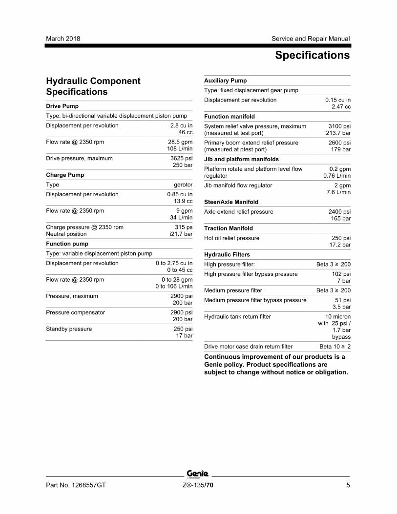
Hydraulic Component Specifications Drive Pump
Type: bi-directional variable displacement piston pump
Displacement per revolution 2.8 cu in 46 cc
Flow rate @ 2350 rpm 28.5 gpm 108 L/min
Drive pressure, maximum 3625 psi 250 bar
Charge Pump
Type gerotor Displacement per revolution 0.85 cu in
13.9 cc Flow rate @ 2350 rpm 9 gpm
34 L/min Charge pressure @ 2350 rpm Neutral position
315 ps i21.7 bar
Function pump
Type: variable displacement piston pump Displacement per revolution 0 to 2.75 cu in
0 to 45 cc Flow rate @ 2350 rpm 0 to 28 gpm
0 to 106 L/min
Pressure, maximum 2900 psi 200 bar
Pressure compensator 2900 psi 200 bar
Standby pressure 250 psi 17 bar
Auxiliary Pump
Type: fixed displacement gear pump Displacement per revolution 0.15 cu in
2.47 cc
Function manifold
System relief valve pressure, maximum (measured at test port)
3100 psi 213.7 bar
Primary boom extend relief pressure (measured at ptest port)
2600 psi 179 bar
Jib and platform manifolds
Platform rotate and platform level flow regulator
0.2 gpm 0.76 L/min
Jib manifold flow regulator 2 gpm 7.6 L/min
Steer/Axle Manifold
Axle extend relief pressure 2400 psi 165 bar
Traction Manifold
Hot oil relief pressure 250 psi 17.2 bar
Hydraulic Filters
High pressure filter: Beta 3 ≥ 200 High pressure filter bypass pressure 102 psi
7 bar Medium pressure filter Beta 3 ≥ 200
Medium pressure filter bypass pressure 51 psi 3.5 bar
Hydraulic tank return filter 10 micron with 25 psi /
1.7 bar bypass
Drive motor case drain return filter Beta 10 ≥ 2
Continuous improvement of our products is a Genie policy. Product specifications are subject to change without notice or obligation.
Service and Repair Manual March 2018
Specifications
6 Z®-135/70 Part No. 1268557GT
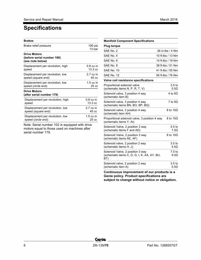
Brakes
Brake relief pressure 190 psi 13 bar
Drive Motors (before serial number 180) (see note below)
Displacement per revolution, high speed
0.8 cu in 13.3 cc
Displacement per revolution, low speed (square end)
2.7 cu in 45 cc
Displacement per revolution, low speed (circle end)
1.5 cu in 25 cc
Drive Motors (after serial number 179)
Displacement per revolution, high speed
0.8 cu in 13.3 cc
Displacement per revolution, low speed (square end)
2.7 cu in 45 cc
Displacement per revolution, low speed (circle end)
1.5 cu in 25 cc
Note: Serial number 102 is equipped with drive motors equal to those used on machines after serial number 179.
Manifold Component Specifications Plug torque
SAE No. 2 36 in-lbs / 4 Nm SAE No. 4 10 ft-lbs / 13 Nm SAE No. 6 14 ft-lbs / 19 Nm SAE No. 8 38 ft-lbs / 51 Nm SAE No. 10 41 ft-lbs / 55 Nm
SAE No. 12 56 ft-lbs / 76 Nm
Valve coil resistance specifications
Proportional solenoid valve (schematic items N, P, R, T, V)
3.5 to 5.5Ω
Solenoid valve, 3 position 4 way (schematic item B)
4 to 6Ω
Solenoid valve, 3 position 4 way (schematic items BN, BO, BP, BQ)
7 to 9Ω
Solenoid valve, 3 position 4 way (schematic item AH)
8 to 10Ω
Proportional solenoid valve, 3 position 4 way (schematic items Y, AI)
8 to 10Ω
Solenoid Valve, 2 position 3 way (schematic items F and AD)
5.5 to 7.5Ω
Solenoid Valve, 2 position 3 way (schematic items AE, AF)
8 to 10Ω
Solenoid valve, 2 position 2 way (schematic items H, J)
3.5 to 5.5Ω
Solenoid Valve, 2 position 3 way (schematic items C, D, G, I, K, AX, AY, BU, BT)
7.5 to 9.5Ω
Solenoid valve, 2 position 2 way (schematic item A)
3.5 to 5.5Ω
Continuous improvement of our products is a Genie policy. Product specifications are subject to change without notice or obligation.
March 2018 Service and Repair Manual
Specifications
Part No. 1268557GT Z®-135/70 7
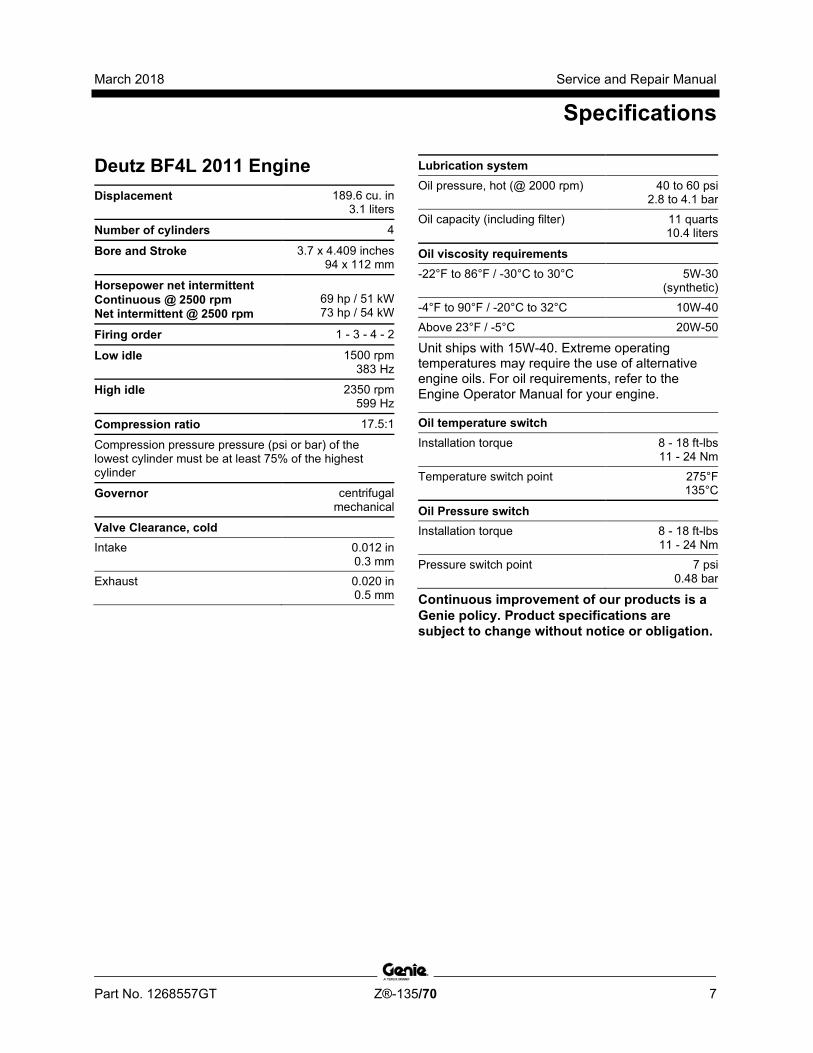
Deutz BF4L 2011 Engine Displacement 189.6 cu. in
3.1 liters
Number of cylinders 4
Bore and Stroke 3.7 x 4.409 inches 94 x 112 mm
Horsepower net intermittent Continuous @ 2500 rpm Net intermittent @ 2500 rpm
69 hp / 51 kW 73 hp / 54 kW
Firing order 1 - 3 - 4 - 2
Low idle 1500 rpm 383 Hz
High idle 2350 rpm 599 Hz
Compression ratio 17.5:1
Compression pressure pressure (psi or bar) of the lowest cylinder must be at least 75% of the highest cylinder
Governor centrifugal mechanical
Valve Clearance, cold
Intake 0.012 in 0.3 mm
Exhaust 0.020 in 0.5 mm
Lubrication system
Oil pressure, hot (@ 2000 rpm) 40 to 60 psi 2.8 to 4.1 bar
Oil capacity (including filter) 11 quarts 10.4 liters
Oil viscosity requirements
-22°F to 86°F / -30°C to 30°C 5W-30 (synthetic)
-4°F to 90°F / -20°C to 32°C 10W-40 Above 23°F / -5°C 20W-50
Unit ships with 15W-40. Extreme operating temperatures may require the use of alternative engine oils. For oil requirements, refer to the Engine Operator Manual for your engine.
Oil temperature switch
Installation torque 8 - 18 ft-lbs 11 - 24 Nm
Temperature switch point 275°F 135°C
Oil Pressure switch
Installation torque 8 - 18 ft-lbs 11 - 24 Nm
Pressure switch point 7 psi 0.48 bar
Continuous improvement of our products is a Genie policy. Product specifications are subject to change without notice or obligation.
Service and Repair Manual March 2018
Specifications
8 Z®-135/70 Part No. 1268557GT
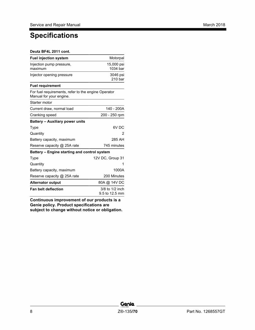
Deutz BF4L 2011 cont.
Fuel injection system Motorpal
Injection pump pressure, maximum
15,000 psi 1034 bar
Injector opening pressure 3046 psi 210 bar
Fuel requirement
For fuel requirements, refer to the engine Operator Manual for your engine. Starter motor Current draw, normal load 140 - 200A
Cranking speed 200 - 250 rpm
Battery – Auxiliary power units Type 6V DC Quantity 2 Battery capacity, maximum 285 AH Reserve capacity @ 25A rate 745 minutes
Battery – Engine starting and control system Type 12V DC, Group 31 Quantity 1 Battery capacity, maximum 1000A Reserve capacity @ 25A rate 200 Minutes
Alternator output 80A @ 14V DC
Fan belt deflection 3/8 to 1/2 inch 9.5 to 12.5 mm
Continuous improvement of our products is a Genie policy. Product specifications are subject to change without notice or obligation.
March 2018 Service and Repair Manual
Specifications
Part No. 1268557GT Z®-135/70 9
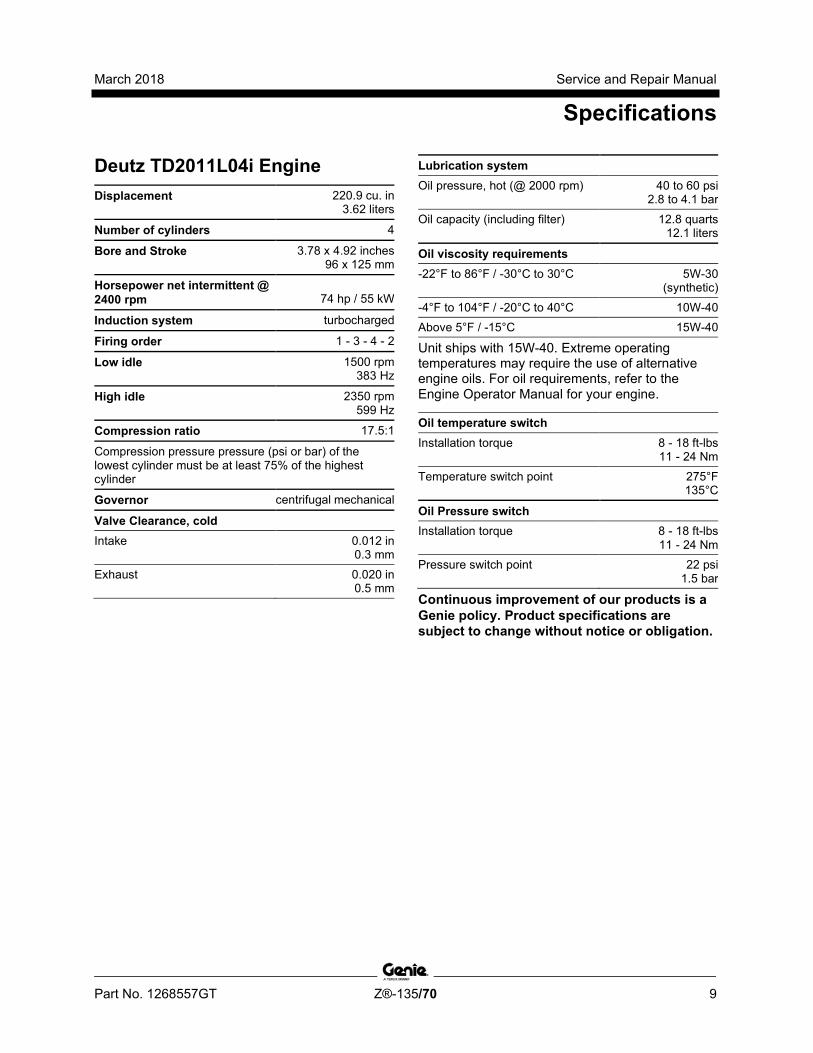
Deutz TD2011L04i Engine Displacement 220.9 cu. in
3.62 liters
Number of cylinders 4
Bore and Stroke 3.78 x 4.92 inches 96 x 125 mm
Horsepower net intermittent @ 2400 rpm
74 hp / 55 kW
Induction system turbocharged
Firing order 1 - 3 - 4 - 2
Low idle 1500 rpm 383 Hz
High idle 2350 rpm 599 Hz
Compression ratio 17.5:1
Compression pressure pressure (psi or bar) of the lowest cylinder must be at least 75% of the highest cylinder
Governor centrifugal mechanical
Valve Clearance, cold
Intake 0.012 in 0.3 mm
Exhaust 0.020 in 0.5 mm
Lubrication system
Oil pressure, hot (@ 2000 rpm) 40 to 60 psi 2.8 to 4.1 bar
Oil capacity (including filter) 12.8 quarts 12.1 liters
Oil viscosity requirements
-22°F to 86°F / -30°C to 30°C 5W-30 (synthetic)
-4°F to 104°F / -20°C to 40°C 10W-40 Above 5°F / -15°C 15W-40
Unit ships with 15W-40. Extreme operating temperatures may require the use of alternative engine oils. For oil requirements, refer to the Engine Operator Manual for your engine.
Oil temperature switch
Installation torque 8 - 18 ft-lbs 11 - 24 Nm
Temperature switch point 275°F 135°C
Oil Pressure switch
Installation torque 8 - 18 ft-lbs 11 - 24 Nm
Pressure switch point 22 psi 1.5 bar
Continuous improvement of our products is a Genie policy. Product specifications are subject to change without notice or obligation.

Service and Repair Manual March 2018
Specifications
10 Z®-135/70 Part No. 1268557GT
Deutz TD2011L04i cont.
Fuel injection system Motorpal
Injection pump pressure, maximum
15,000 psi 1034 bar
Injector opening pressure 3046 psi 210 bar
Fuel requirement
For fuel requirements, refer to the engine Operator Manual for your engine. Starter motor Current draw, normal load 140 - 200A
Cranking speed 250 - 350 rpm
Battery – Auxiliary power units Type 6V DC Quantity 2 Battery capacity, maximum 285 AH Reserve capacity @ 25A rate 745 minutes
Battery – Engine starting and control system Type 12V DC, Group 31 Quantity 1 Battery capacity, maximum 1000A Reserve capacity @ 25A rate 200 Minutes
Alternator output 80A @ 14V DC
Fan belt deflection 3/8 to 1/2 inch 9.5 to 12.5 mm
Continuous improvement of our products is a Genie policy. Product specifications are subject to change without notice or obligation.
March 2018 Service and Repair Manual
Specifications
Part No. 1268557GT Z®-135/70 11
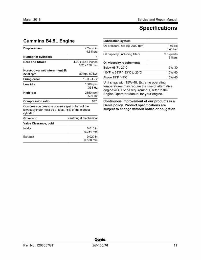
Cummins B4.5L Engine Displacement 275 cu. in
4.5 liters
Number of cylinders 4
Bore and Stroke 4.02 x 5.42 inches 102 x 138 mm
Horsepower net intermittent @ 2200 rpm
80 hp / 60 kW
Firing order 1 - 3 - 4 - 2
Low idle 1300 rpm 368 Hz
High idle 2350 rpm 599 Hz
Compression ratio 18:1
Compression pressure pressure (psi or bar) of the lowest cylinder must be at least 75% of the highest cylinder
Governor centrifugal mechanical
Valve Clearance, cold
Intake 0.010 in 0.254 mm
Exhaust 0.020 in 0.508 mm
Lubrication system
Oil pressure, hot (@ 2000 rpm) 50 psi 3.45 bar
Oil capacity (including filter) 9.5 quarts 9 liters
Oil viscosity requirements
Below 68°F / 20°C 5W-30 -10°F to 68°F / -23°C to 20°C 10W-40 Above 15°F / -9°C 15W-40
Unit ships with 15W-40. Extreme operating temperatures may require the use of alternative engine oils. For oil requirements, refer to the Engine Operator Manual for your engine.
Continuous improvement of our products is a Genie policy. Product specifications are subject to change without notice or obligation.
Service and Repair Manual March 2018
Specifications
12 Z®-135/70 Part No. 1268557GT
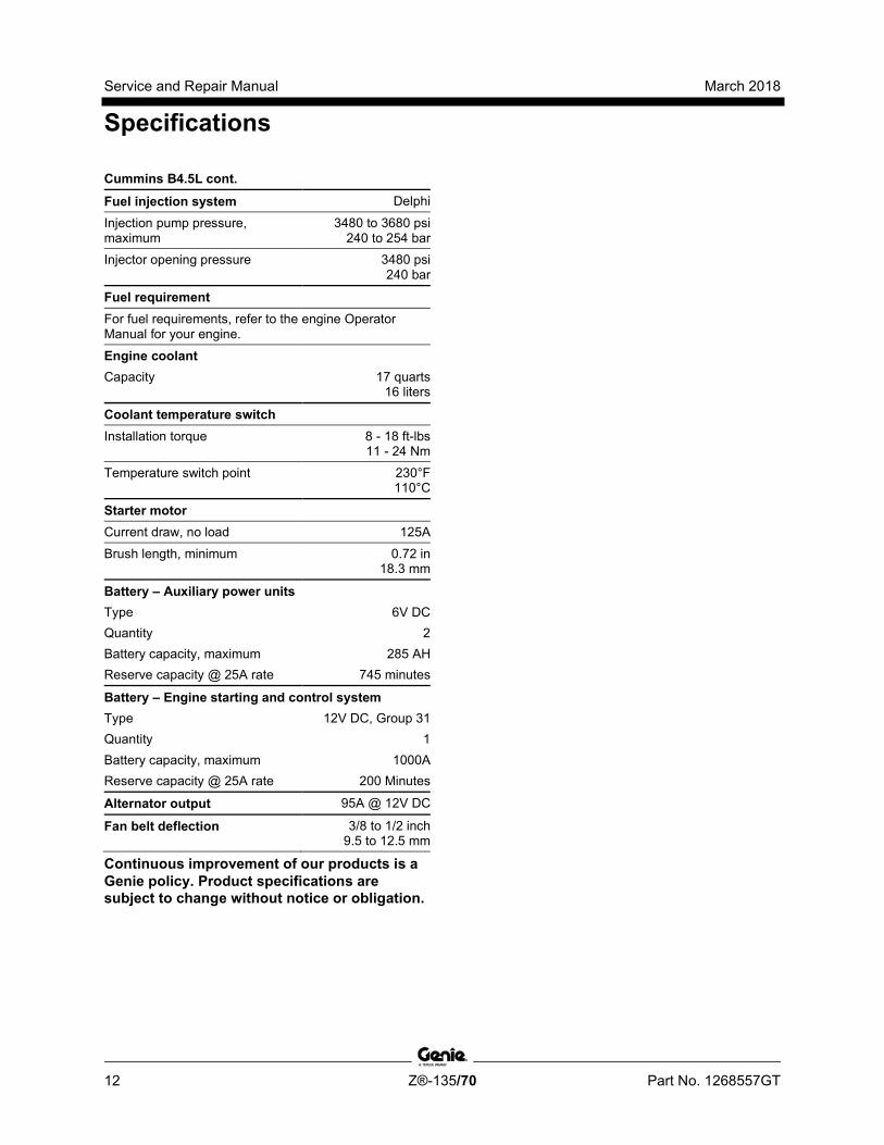
Cummins B4.5L cont.
Fuel injection system Delphi
Injection pump pressure, maximum
3480 to 3680 psi 240 to 254 bar
Injector opening pressure 3480 psi 240 bar
Fuel requirement
For fuel requirements, refer to the engine Operator Manual for your engine.
Engine coolant Capacity 17 quarts
16 liters
Coolant temperature switch
Installation torque 8 - 18 ft-lbs 11 - 24 Nm
Temperature switch point 230°F 110°C
Starter motor
Current draw, no load 125A
Brush length, minimum 0.72 in 18.3 mm
Battery – Auxiliary power units Type 6V DC Quantity 2 Battery capacity, maximum 285 AH Reserve capacity @ 25A rate 745 minutes
Battery – Engine starting and control system Type 12V DC, Group 31 Quantity 1 Battery capacity, maximum 1000A Reserve capacity @ 25A rate 200 Minutes
Alternator output 95A @ 12V DC
Fan belt deflection 3/8 to 1/2 inch 9.5 to 12.5 mm
Continuous improvement of our products is a Genie policy. Product specifications are subject to change without notice or obligation.

March 2018 Service and Repair Manual
Specifications
Part No. 1268557GT Z®-135/70 13
Cummins B3.3T Engine Displacement 199 cu. in
3.26 liters
Number of cylinders 4
Bore and Stroke 3.74 x 4.53 inches 95 x 115 mm
Horsepower net intermittent @ 2200 rpm
80 hp / 60 kW
Firing order 1 - 2 - 4 - 3
Low idle 1300 rpm 368 Hz
High idle 2350 rpm 599 Hz
Compression ratio 17:1
Compression pressure pressure (psi or bar) of the lowest cylinder must be at least 75% of the highest cylinder
Valve Clearance, cold
Intake 0.014 in 0.35 mm
Exhaust 0.020 in 0.508 mm
Lubrication system
Oil pressure, hot (@ 2000 rpm) 31 psi 72 bar
Oil capacity (including filter) 9 quarts 8.5 liters
Oil viscosity requirements
Below 68°F / 20°C 5W-30 -10°F to 68°F / -23°C to 20°C 10W-40 Above 14°F / -10°C 15W-40
Unit ships with 15W-40. Extreme operating temperatures may require the use of alternative engine oils. For oil requirements, refer to the Engine Operator Manual for your engine.
Continuous improvement of our products is a Genie policy. Product specifications are subject to change without notice or obligation.

Service and Repair Manual March 2018
Specifications
14 Z®-135/70 Part No. 1268557GT
Cummins B3.3T cont.
Fuel injection system Zexel
Injection pump pressure, maximum
12,000 psi 827 bar
Fuel requirement
For fuel requirements, refer to the engine Operator Manual for your engine.
Engine coolant Capacity 9.1 quarts
8.6 liters
Starter motor
Current draw, maximum load 550A Cranking speed 130 rpm
Battery – Auxiliary power units Type 6V DC Quantity 2 Battery capacity, maximum 285 AH Reserve capacity @ 25A rate 745 minutes
Battery – Engine starting and control system Type 12V DC, Group 31 Quantity 1 Battery capacity, maximum 1000A Reserve capacity @ 25A rate 200 Minutes
Alternator output 120A @ 12V DC
Fan belt deflection 3/8 to 1/2 inch 9.5 to 12.5 mm
Continuous improvement of our products is a Genie policy. Product specifications are subject to change without notice or obligation.
March 2018 Service and Repair Manual
Specifications
Part No. 1268557GT Z®-135/70 15
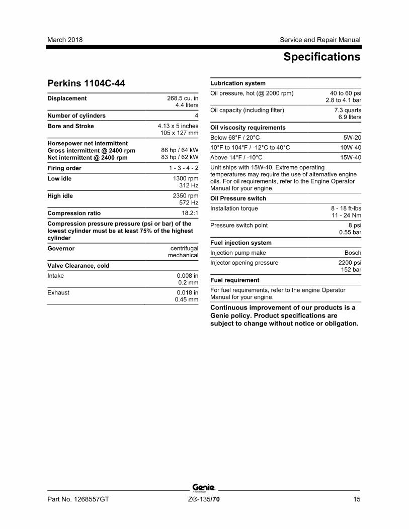
Perkins 1104C-44 Displacement 268.5 cu. in
4.4 liters
Number of cylinders 4
Bore and Stroke 4.13 x 5 inches 105 x 127 mm
Horsepower net intermittent Gross intermittent @ 2400 rpm Net intermittent @ 2400 rpm
86 hp / 64 kW 83 hp / 62 kW
Firing order 1 - 3 - 4 - 2
Low idle 1300 rpm 312 Hz
High idle 2350 rpm 572 Hz
Compression ratio 18.2:1
Compression pressure pressure (psi or bar) of the lowest cylinder must be at least 75% of the highest cylinder
Governor centrifugal mechanical
Valve Clearance, cold
Intake 0.008 in 0.2 mm
Exhaust 0.018 in 0.45 mm
Lubrication system
Oil pressure, hot (@ 2000 rpm) 40 to 60 psi 2.8 to 4.1 bar
Oil capacity (including filter) 7.3 quarts 6.9 liters
Oil viscosity requirements
Below 68°F / 20°C 5W-20 10°F to 104°F / -12°C to 40°C 10W-40 Above 14°F / -10°C 15W-40 Unit ships with 15W-40. Extreme operating temperatures may require the use of alternative engine oils. For oil requirements, refer to the Engine Operator Manual for your engine.
Oil Pressure switch
Installation torque 8 - 18 ft-lbs 11 - 24 Nm
Pressure switch point 8 psi 0.55 bar
Fuel injection system
Injection pump make Bosch Injector opening pressure 2200 psi
152 bar
Fuel requirement
For fuel requirements, refer to the engine Operator Manual for your engine.
Continuous improvement of our products is a Genie policy. Product specifications are subject to change without notice or obligation.
Service and Repair Manual March 2018
Specifications
16 Z®-135/70 Part No. 1268557GT
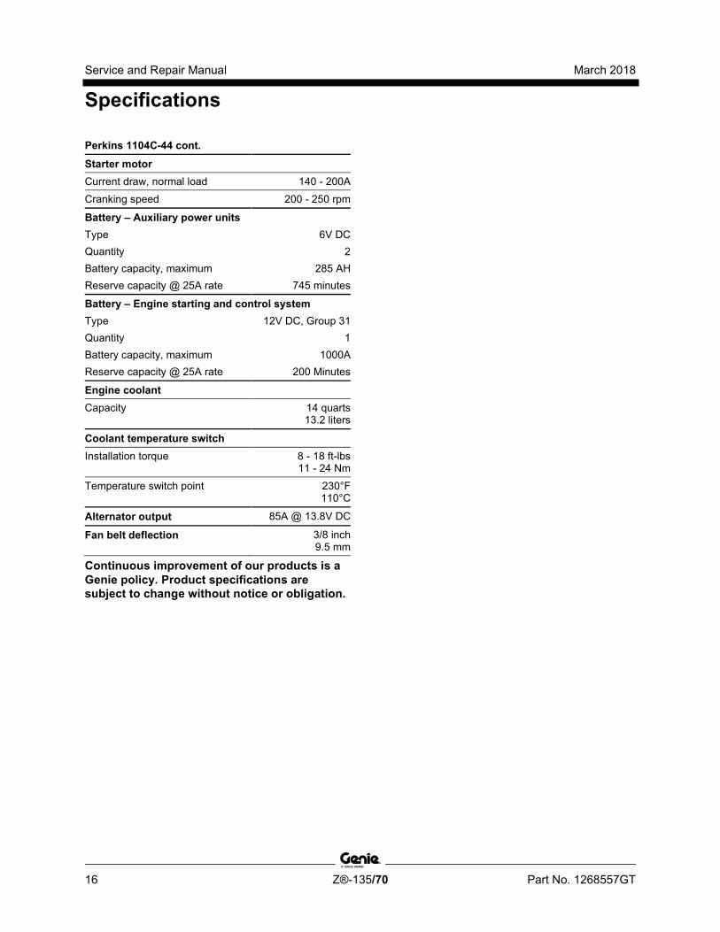
Perkins 1104C-44 cont.
Starter motor
Current draw, normal load 140 - 200A
Cranking speed 200 - 250 rpm
Battery – Auxiliary power units Type 6V DC Quantity 2 Battery capacity, maximum 285 AH Reserve capacity @ 25A rate 745 minutes
Battery – Engine starting and control system Type 12V DC, Group 31 Quantity 1 Battery capacity, maximum 1000A Reserve capacity @ 25A rate 200 Minutes
Engine coolant
Capacity 14 quarts 13.2 liters
Coolant temperature switch
Installation torque 8 - 18 ft-lbs 11 - 24 Nm
Temperature switch point 230°F 110°C
Alternator output 85A @ 13.8V DC
Fan belt deflection 3/8 inch 9.5 mm
Continuous improvement of our products is a Genie policy. Product specifications are subject to change without notice or obligation.
March 2018 Service and Repair Manual
Specifications
Part No. 1268557GT Z®-135/70 17
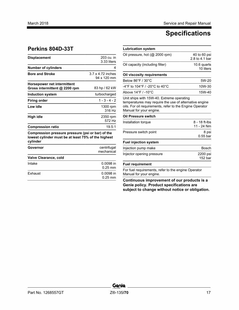
Perkins 804D-33T Displacement 203 cu. in
3.33 liters
Number of cylinders 4
Bore and Stroke 3.7 x 4.72 inches 94 x 120 mm
Horsepower net intermittent Gross intermittent @ 2200 rpm
83 hp / 62 kW
Induction system turbocharged
Firing order 1 - 3 - 4 - 2
Low idle 1300 rpm 316 Hz
High idle 2350 rpm 572 Hz
Compression ratio 19.5:1
Compression pressure pressure (psi or bar) of the lowest cylinder must be at least 75% of the highest cylinder
Governor centrifugal mechanical
Valve Clearance, cold
Intake 0.0098 in 0.25 mm
Exhaust 0.0098 in 0.25 mm
Lubrication system
Oil pressure, hot (@ 2000 rpm) 40 to 60 psi 2.8 to 4.1 bar
Oil capacity (including filter) 10.6 quarts 10 liters
Oil viscosity requirements
Below 86°F / 30°C 5W-20 -4°F to 104°F / -20°C to 40°C 10W-30 Above 14°F / -10°C 15W-40 Unit ships with 15W-40. Extreme operating temperatures may require the use of alternative engine oils. For oil requirements, refer to the Engine Operator Manual for your engine.
Oil Pressure switch
Installation torque 8 - 18 ft-lbs 11 - 24 Nm
Pressure switch point 8 psi 0.55 bar
Fuel injection system
Injection pump make Bosch Injector opening pressure 2200 psi
152 bar
Fuel requirement
For fuel requirements, refer to the engine Operator Manual for your engine.
Continuous improvement of our products is a Genie policy. Product specifications are subject to change without notice or obligation.
Service and Repair Manual March 2018
Specifications
18 Z®-135/70 Part No. 1268557GT
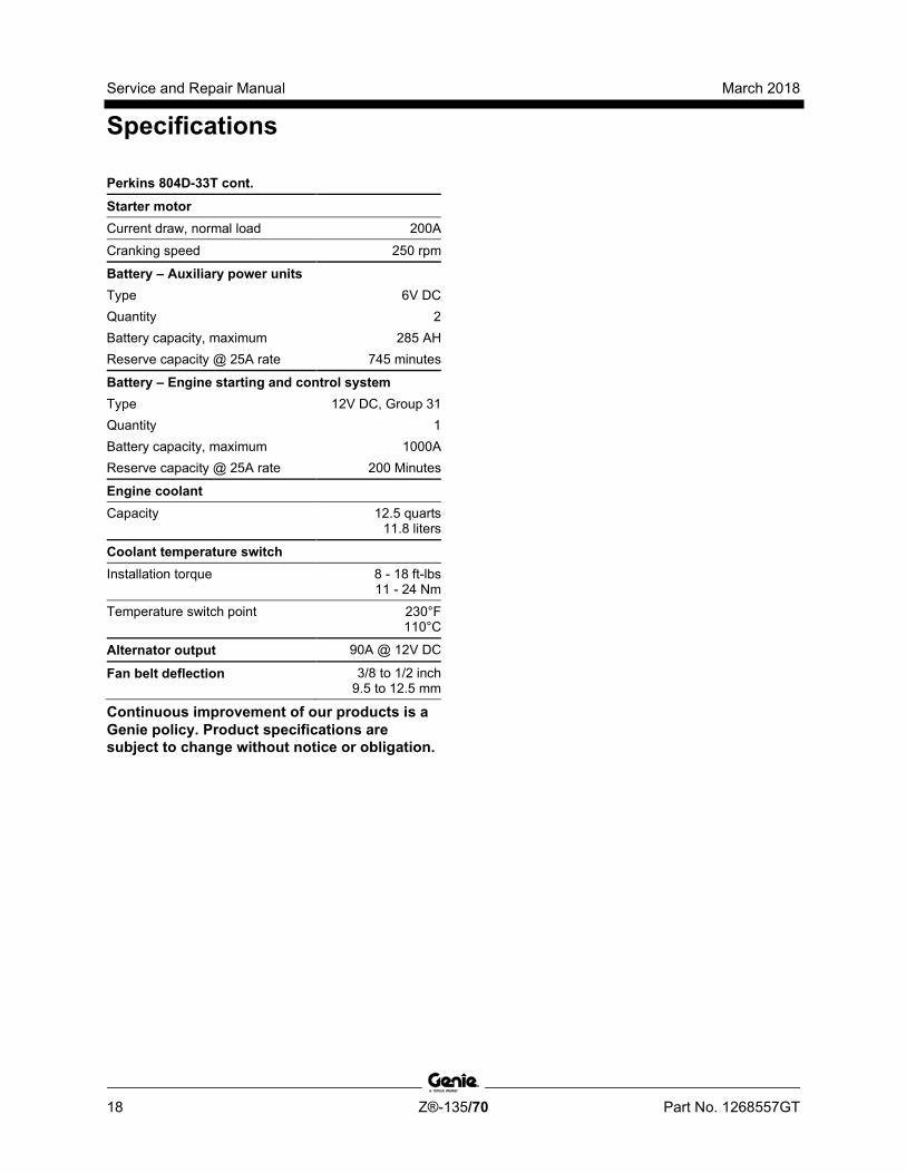
Perkins 804D-33T cont.
Starter motor
Current draw, normal load 200A
Cranking speed 250 rpm
Battery – Auxiliary power units Type 6V DC Quantity 2 Battery capacity, maximum 285 AH Reserve capacity @ 25A rate 745 minutes
Battery – Engine starting and control system Type 12V DC, Group 31 Quantity 1 Battery capacity, maximum 1000A Reserve capacity @ 25A rate 200 Minutes
Engine coolant
Capacity 12.5 quarts 11.8 liters
Coolant temperature switch
Installation torque 8 - 18 ft-lbs 11 - 24 Nm
Temperature switch point 230°F 110°C
Alternator output 90A @ 12V DC
Fan belt deflection 3/8 to 1/2 inch 9.5 to 12.5 mm
Continuous improvement of our products is a Genie policy. Product specifications are subject to change without notice or obligation.

March 2018 Service and Repair Manual
Specifications
Part No. 1268557GT Z®-135/70 19
Machine Torque Specifications Platform Rotator
1-8 center bolt, GR 5 480 ft-lbs 651 Nm
3/8 -16 bolts, GR 8 44 ft-lbs 60 Nm
Turntable rotate assembly
Rotate bearing mounting bolts, lubricated (3/4 -10 SHC)
320 ft-lbs 434 Nm
Rotate bearing mounting bolts, lubricated (5/8 -11 SHC)
180 ft-lbs 244 Nm
Rotate drive hub mounting bolts, lubricated 80 ft-lbs 108 Nm
Drive motor mounting bolts, dry 75 ft-lbs 102 Nm
Drive motor mounting bolts, lubricated 56 ft-lbs 76 Nm
Backlash plate mounting bolts, lubricated 320 ft-lbs 434 Nm
Drive motors and hubs
Drive hub mounting bolts, lubricated 180 ft-lbs 217 Nm
Drive motor mounting bolts, dry 75 ft-lbs 102 Nm
Drive motor mounting bolts, lubricated 56 ft-lbs 76 Nm
Engine vibration isolators
Mounting bolts, dry 60 ft-lbs 81 Nm
Mounting bolts, lubricated 45 ft-lbs 61 Nm
Continuous improvement of our products is a Genie policy. Product specifications are subject to change without notice or obligation.
Service and Repair Manual March 2018
Specifications
20 Z®-135/70 Part No. 1268557GT
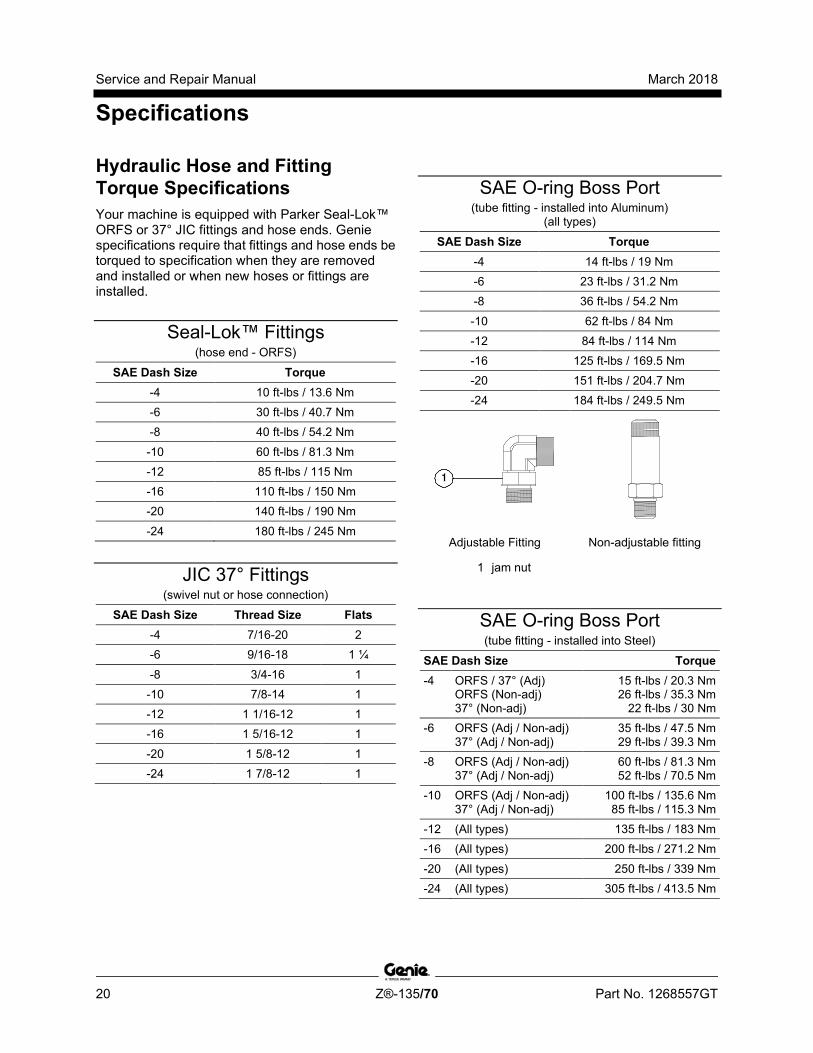
Hydraulic Hose and Fitting Torque Specifications Your machine is equipped with Parker Seal-Lok™ ORFS or 37° JIC fittings and hose ends. Genie specifications require that fittings and hose ends be torqued to specification when they are removed and installed or when new hoses or fittings are installed.
Seal-Lok™ Fittings (hose end - ORFS)
SAE Dash Size Torque -4 10 ft-lbs / 13.6 Nm -6 30 ft-lbs / 40.7 Nm -8 40 ft-lbs / 54.2 Nm
-10 60 ft-lbs / 81.3 Nm -12 85 ft-lbs / 115 Nm -16 110 ft-lbs / 150 Nm -20 140 ft-lbs / 190 Nm
-24 180 ft-lbs / 245 Nm
JIC 37° Fittings (swivel nut or hose connection)
SAE Dash Size Thread Size Flats -4 7/16-20 2 -6 9/16-18 1 ¼
-8 3/4-16 1 -10 7/8-14 1 -12 1 1/16-12 1 -16 1 5/16-12 1
-20 1 5/8-12 1 -24 1 7/8-12 1
SAE O-ring Boss Port (tube fitting - installed into Aluminum)
(all types)
SAE Dash Size Torque -4 14 ft-lbs / 19 Nm -6 23 ft-lbs / 31.2 Nm -8 36 ft-lbs / 54.2 Nm
-10 62 ft-lbs / 84 Nm -12 84 ft-lbs / 114 Nm -16 125 ft-lbs / 169.5 Nm -20 151 ft-lbs / 204.7 Nm -24 184 ft-lbs / 249.5 Nm
Adjustable Fitting Non-adjustable fitting
1 jam nut
SAE O-ring Boss Port (tube fitting - installed into Steel)
SAE Dash Size Torque -4 ORFS / 37° (Adj)
ORFS (Non-adj) 37° (Non-adj)
15 ft-lbs / 20.3 Nm 26 ft-lbs / 35.3 Nm
22 ft-lbs / 30 Nm -6 ORFS (Adj / Non-adj)
37° (Adj / Non-adj) 35 ft-lbs / 47.5 Nm 29 ft-lbs / 39.3 Nm
-8 ORFS (Adj / Non-adj) 37° (Adj / Non-adj)
60 ft-lbs / 81.3 Nm 52 ft-lbs / 70.5 Nm
-10 ORFS (Adj / Non-adj) 37° (Adj / Non-adj)
100 ft-lbs / 135.6 Nm 85 ft-lbs / 115.3 Nm
-12 (All types) 135 ft-lbs / 183 Nm -16 (All types) 200 ft-lbs / 271.2 Nm
-20 (All types) 250 ft-lbs / 339 Nm -24 (All types) 305 ft-lbs / 413.5 Nm
March 2018 Service and Repair Manual
Specifications
Part No. 1268557GT Z®-135/70 21
Torque Procedure
Seal-Lok™ fittings 1 Replace the O-ring. The O-ring must be
replaced anytime the seal has been broken. The O-ring cannot be re-used if the fitting or hose end has been tightened beyond finger tight.
Note: The O-ring in Parker Seal Lok™ fittings and hose end are custom-size O-rings. They are not standard size O-rings. They are available in the O-ring field service kit (Genie part number 49612).
2 Lubricate the O-ring before installation.
3 Be sure the O-ring face seal is seated and retained properly.
4 Position the tube and nut squarely on the face seal end of the fitting, and tighten the nut finger tight.
5 Tighten the nut or fitting to the appropriate torque. Refer to the appropriate torque chart in this section.
6 Operate all machine functions and inspect the hose, fittings and related components to confirm there are no leaks.
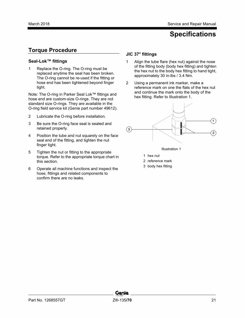
JIC 37° fittings 1 Align the tube flare (hex nut) against the nose
of the fitting body (body hex fitting) and tighten the hex nut to the body hex fitting to hand tight, approximately 30 in-lbs / 3.4 Nm.
2 Using a permanent ink marker, make a reference mark on one the flats of the hex nut and continue the mark onto the body of the hex fitting. Refer to Illustration 1.
Illustration 1
1 hex nut 2 reference mark 3 body hex fitting
Service and Repair Manual March 2018
Specifications
22 Z®-135/70 Part No. 1268557GT
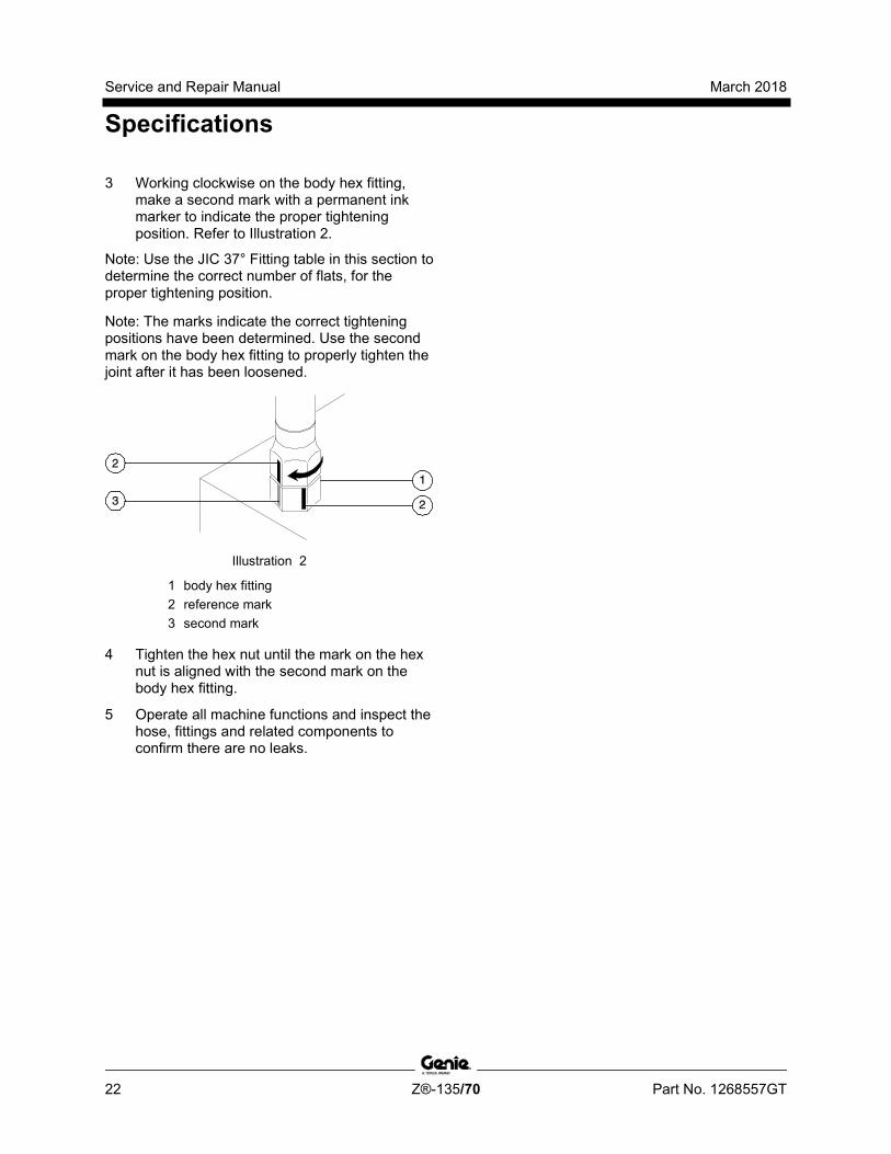
3 Working clockwise on the body hex fitting, make a second mark with a permanent ink marker to indicate the proper tightening position. Refer to Illustration 2.
Note: Use the JIC 37° Fitting table in this section to determine the correct number of flats, for the proper tightening position.
Note: The marks indicate the correct tightening positions have been determined. Use the second mark on the body hex fitting to properly tighten the joint after it has been loosened.
Illustration 2
1 body hex fitting 2 reference mark 3 second mark
4 Tighten the hex nut until the mark on the hex nut is aligned with the second mark on the body hex fitting.
5 Operate all machine functions and inspect the hose, fittings and related components to confirm there are no leaks.
March 2018 Service and Repair Manual
Specifications
Part No. 1268557GT Z®-135/70 23
T

Service and Repair Manual March 2018
Repair Procedures
24 Z®-135/70 Part No. 1268557GT
Section 3 Repair Pr ocedures
Observe and Obey: Repair procedures shall be completed by a
person trained and qualified on the repair of this machine.
Immediately tag and remove from service a damaged or malfunctioning machine.
Repair any machine damage or malfunction before operating the machine.
Before Repairs Start: Read, understand and obey the safety rules
and operating instructions in the appropriate operator's manual on your machine.
Be sure that all necessary tools and parts are available and ready for use.
Use only Genie approved replacement parts.
Read each procedure completely and adhere to the instructions. Attempting shortcuts may produce hazardous conditions.
Machine Configuration: Unless otherwise specified, perform each
repair procedure with the machine in the following configuration:
• Machine parked on a firm, level surface
• Key switch in the off position with the key removed
• The red Emergency Stop button in the off position at both the ground and platform controls
• Wheels chocked
• All external AC power supply disconnected from the machine
• Boom in the stowed position
• Turntable secured with the turntable rotation lock
March 2018 Service and Repair Manual
Repair Procedures
Part No. 1268557GT Z®-135/70 25
About This Section Most of the procedures in this section should only be performed by trained service professional in a suitably equipped workshop. Select the appropriate repair procedure after troubleshooting the problem.
Perform disassembly procedures to the point where repairs can be completed. Then to re-assemble, perform the disassembly steps in reverse order.
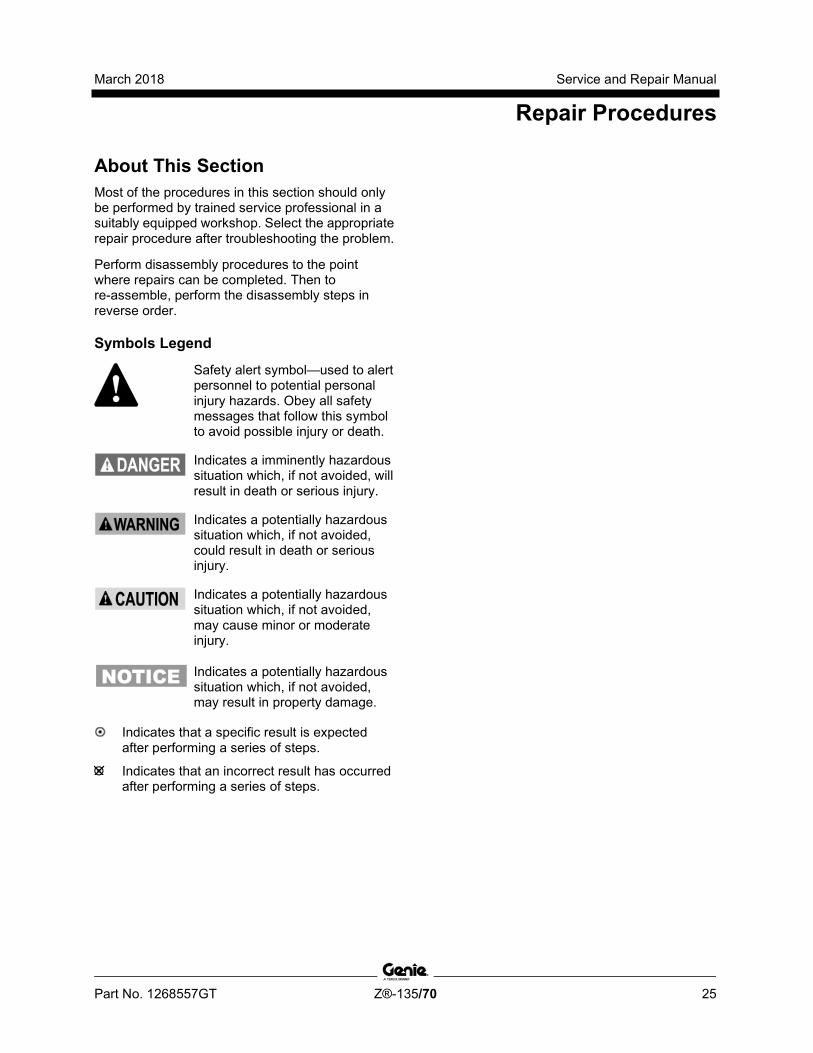
Symbols Legend
Safety alert symbol—used to alert personnel to potential personal injury hazards. Obey all safety messages that follow this symbol to avoid possible injury or death.
Indicates a imminently hazardous situation which, if not avoided, will result in death or serious injury.
Indicates a potentially hazardous situation which, if not avoided, could result in death or serious injury.
Indicates a potentially hazardous situation which, if not avoided, may cause minor or moderate injury.
Indicates a potentially hazardous situation which, if not avoided, may result in property damage.
Indicates that a specific result is expected after performing a series of steps.
Indicates that an incorrect result has occurred after performing a series of steps.
Service and Repair Manual March 2018
Platform Controls
26 Z®-135/70 Part No. 1268557GT
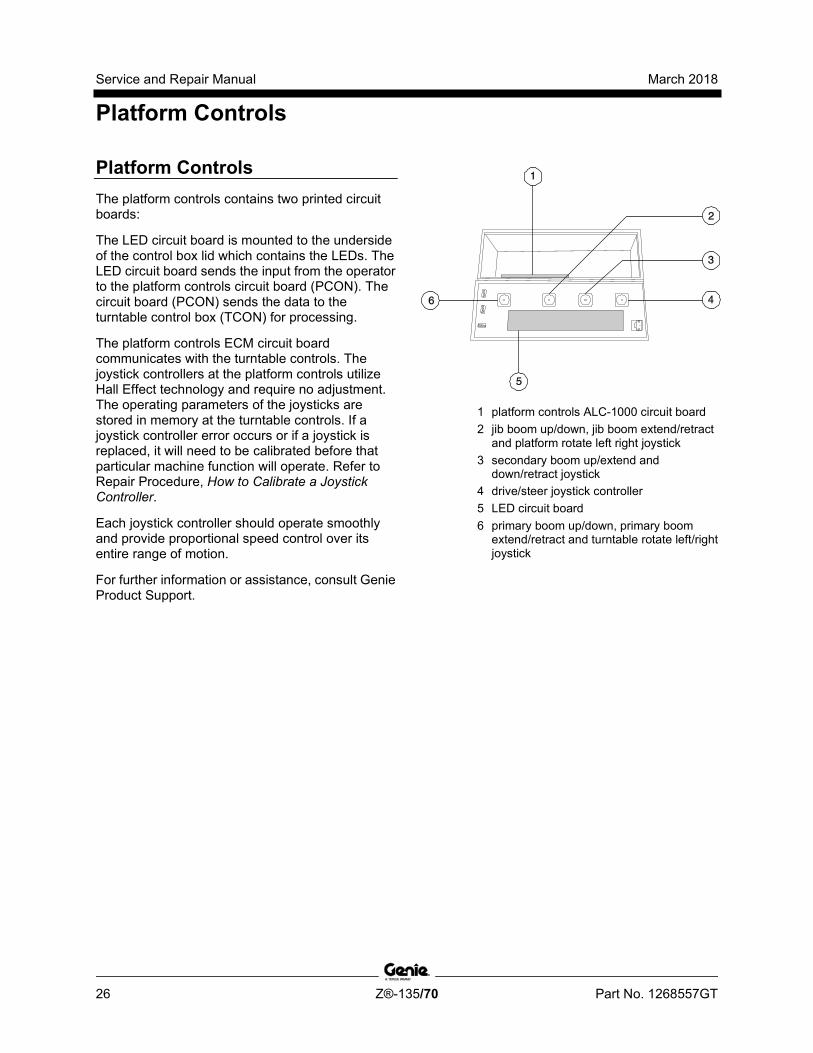
Platform Controls The platform controls contains two printed circuit boards:
The LED circuit board is mounted to the underside of the control box lid which contains the LEDs. The LED circuit board sends the input from the operator to the platform controls circuit board (PCON). The circuit board (PCON) sends the data to the turntable control box (TCON) for processing.
The platform controls ECM circuit board communicates with the turntable controls. The joystick controllers at the platform controls utilize Hall Effect technology and require no adjustment. The operating parameters of the joysticks are stored in memory at the turntable controls. If a joystick controller error occurs or if a joystick is replaced, it will need to be calibrated before that particular machine function will operate. Refer to Repair Procedure, How to Calibrate a Joystick Controller.
Each joystick controller should operate smoothly and provide proportional speed control over its entire range of motion.
For further information or assistance, consult Genie Product Support.
1 platform controls ALC-1000 circuit board 2 jib boom up/down, jib boom extend/retract
and platform rotate left right joystick 3 secondary boom up/extend and
down/retract joystick 4 drive/steer joystick controller 5 LED circuit board 6 primary boom up/down, primary boom
extend/retract and turntable rotate left/right joystick
March 2018 Service and Repair Manual
Platform Controls
Part No. 1268557GT Z®-135/70 27
1-1 Platform Circuit Board
Electrocution/burn hazard. Contact with electrically charged circuits could result in death or serious injury. Remove all rings, watches and other jewelry.
Note: When the platform circuit board is replaced, jib bellcrank and platform level will need to be calibrated. Refer to Repair Procedures, How to Calibrate the Jib Boom Bellcrank Angle Sensor or How to Calibrate the Platform Level Sensor.
How to Remove the Circuit Board 1 Push in the red Emergency Stop button to the
off position at both the ground and platform controls.
2 Locate the cables that connect to the bottom of the control box. Number each cable and its location at the control box.
3 Disconnect the cables from the bottom of the platform control box.
4 Remove the control cable receptacle retaining fasteners from the bottom of the platform control box.
5 Remove the platform control box lid retaining fasteners. Open the control box lid.
6 Locate the circuit board mounted to the inside of the platform control box.
7 Attach a grounded wrist strap to the ground screw inside the control box.
Electrocution/burn hazard. Contact with electrically charged circuits could result in death or serious injury. Remove all rings, watches and other jewelry.
Component damage hazard. Electrostatic discharge (ESD) can damage printed circuit board components. Maintain firm contact with a metal part of the machine that is grounded at all times when handling printed circuit boards OR use a grounded wrist strap.
8 Tag and carefully disconnect the wire connectors from the circuit board.
9 Tag and disconnect the ribbon cable from the LED circuit board.
10 Remove the circuit board mounting fasteners.
11 Carefully remove the circuit board from the control box.
Service and Repair Manual March 2018
Platform Controls
28 Z®-135/70 Part No. 1268557GT
How to R emove the LED Circui t Board
How to Remove the LED Circuit Board 1 Push in the red Emergency Stop button to the
off position at both the ground and platform controls.
2 Remove the platform control box lid retaining fasteners. Open the control box lid.
3 Locate the circuit board mounted to the inside of the platform control box.
Electrocution/burn hazard. Contact with electrically charged circuits could result in death or serious injury. Remove all rings, watches and other jewelry.
Component damage hazard. Electrostatic discharge (ESD) can damage printed circuit board components. Maintain firm contact with a metal part of the machine that is grounded at all times when handling printed circuit boards OR use a grounded wrist strap.
4 Tag and carefully disconnect the ribbon cables from the membrane circuit board.
5 Remove the circuit board mounting fasteners.
6 Carefully remove the LED circuit board from the platform control box lid. Do not lose the plastic spacers.
Note: When installing the LED circuit board, be sure the plastic spacers are installed between the circuit board and the control box lid.

March 2018 Service and Repair Manual
Platform Controls
Part No. 1268557GT Z®-135/70 29
1-2 Membrane Decal
How to Replace the Membrane Decal The membrane decal is a special decal that consists of a decal with an electronic membrane on the backside. The membrane contains touch sensitive areas that, when pushed, activate the machine functions. The membrane contains touch sensitive areas that activate the machine functions.
1 Push in the red Emergency Stop button to the off position at both the ground and platform controls.
2 Remove the platform control box lid retaining fasteners. Open the control box lid.
3 Tag and carefully disconnect the two ribbon cables from the membrane circuit board.
Electrocution/burn hazard. Contact with electrically charged circuits could result in death or serious injury. Remove all rings, watches and other jewelry.
Component damage hazard. Electrostatic discharge (ESD) can damage printed circuit board components. Maintain firm contact with a metal part of the machine that is grounded at all times when handling printed circuit boards OR use a grounded wrist strap.
4 Close the control box lid.
5 Remove the platform controls decal from the platform control box.
6 Carefully remove the membrane decal from the control box lid while guiding the ribbon cables out of the control box lid.
7 Remove any decal adhesive from the control box lid with a mild solvent.
Note: Do not allow any solvent to come in contact with the membrane circuit board.
8 Install the new membrane decal while guiding the ribbon cables through the control box lid.
Note: Be sure that all LED locations on the membrane decal align with the LEDs on the membrane circuit board.
9 Install a new platform controls decal over the membrane decal.
10 Open the control box lid and carefully connect the ribbon cables from the membrane decal to the membrane circuit board.

Service and Repair Manual March 2018
Platform Controls
30 Z®-135/70 Part No. 1268557GT
1-3 Joysticks
How to Calibrate a Joystick The joystick controllers on this machine utilize digital Hall Effect technology for proportional control. If a joystick controller is disconnected or replaced, it must be calibrated before that particular machine function will operate.
Note: The joystick must be calibrated before the threshold, max-out or ramping can be set.
Note: After each joystick is calibrated, check the display at the ground control box. There should be no calibration faults shown on the display. If calibration faults exist, repeat procedure for that joystick controlled function.
Note: Perform this procedure with the engine off.
Note: Use the following chart to identify the description of each LCD screen control button used in this procedure.
Plus Minus Previous Enter
Drive functions:
1 Turn the key switch to the off position.
2 Press and hold the enter button on the ground control panel while turning the key switch to platform controls. Hold the enter button for approximately 5 seconds.
3 Press the minus button twice, then press the enter button twice.
4 Use the scroll button to scroll through the menu until DELETE DRIVE JOYSTICK DEFAULTS is displayed.
5 Press the plus button to select YES, then press the enter button.
6 Do not start the engine.
7 Locate the drive/steer joystick.
8 Move the drive/steer joystick full stroke in the forward direction and hold for 5 seconds, then return to the center or neutral position.
9 Move the drive/steer joystick full stroke in the reverse direction and hold for 5 seconds, then return to the center or neutral position.
Result: The alarm at the ground controls should sound for a successful calibration.
March 2018 Service and Repair Manual
Platform Controls
Part No. 1268557GT Z®-135/70 31
Steer functions:
1 Turn the key switch to the off position.
2 Press and hold the enter button on the ground control panel while turning the key switch to platform controls. Hold the enter button for approximately 5 seconds.
3 Press the minus button twice, then press the enter button twice.
4 Use the scroll button to scroll through the menu until DELETE STEER JOYSTICK DEFAULTS is displayed.
5 Press the plus button to select YES, then press the enter button.
6 Do not start the engine.
7 Locate the drive/steer joystick.
8 Move the drive/steer joystick or thumb rocker switch (if equipped) full stroke in the left direction and hold for 5 seconds, then return to the center or neutral position.
9 Move the drive/steer joystick or thumb rocker switch (if equipped) full stroke in the right direction and hold for 5 seconds, then return to the center or neutral position.
Result: The alarm at the ground controls should sound for a successful calibration.
Secondary boom up/down and extend/retract functions:
1 Turn the key switch to the off position.
2 Press and hold the enter button on the ground control panel while turning the key switch to platform controls. Hold the enter button for approximately 5 seconds.
3 Press the minus button twice, then press the enter button twice.
4 Use the scroll button to scroll through the menu until DELETE SECONDARY BOOM JOYSTICK DEFAULTS is displayed.
5 Press the plus button to select YES, then press the enter button.
6 Do not start the engine.
7 Locate the secondary boom up/down and extend/retract joystick.
8 Move the secondary boom up/down and extend/retract joystick full stroke in the up/extend direction and hold for 5 seconds, then return to the center or neutral position.
9 Move the secondary boom up/down and extend/retract joystick full stroke in the down/retract direction and hold for 5 seconds, then return to the center or neutral position.
Result: The alarm at the ground controls should sound for a successful calibration.

Service and Repair Manual March 2018
Platform Controls
32 Z®-135/70 Part No. 1268557GT
Primary boom extend/retract functions:
1 Turn the key switch to the off position.
2 Press and hold the enter button on the ground control panel while turning the key switch to platform controls. Hold the enter button for approximately 5 seconds.
3 Press the minus button twice, then press the enter button twice.
4 Use the scroll button to scroll through the menu until DELETE PRIMARY BOOM EXTEND/RETRACT JOYSTICK DEFAULTS is displayed.
5 Press the plus button to select YES, then press the enter button.
6 Do not start the engine.
7 Locate the thumb rocker switch on top of the primary boom/turntable rotate joystick.
8 Move the primary boom extend/retract thumb rocker switch full stroke in the extend direction and hold for 5 seconds, then return to thecenter or neutral position.
9 Move the primary boom extend/retract thumb rocker switch full stroke in the retract direction and hold for 5 seconds, then return to the center or neutral position.
Result: The alarm at the ground controls should sound for a successful calibration.
Primary boom up/down functions:
1 Turn the key switch to the off position.
2 Press and hold the enter button on the ground control panel while turning the key switch to platform controls. Hold the enter button for approximately 5 seconds.
3 Press the minus button twice, then press the enter button twice.
4 Use the scroll button to scroll through the menu until DELETE PRIMARY BOOM UP/DOWN JOYSTICK DEFAULTS is displayed.
5 Press the plus button to select YES, then press the enter button.
6 Do not start the engine.
7 Locate the primary boom/turntable rotate joystick.
8 Move the boom/turntable rotate joystick full stroke in the up direction and hold for 5 seconds, then return to the center or neutral position.
9 Move the boom/turntable rotate joystick full stroke in the down direction and hold for 5 seconds, then return to the center or neutral position.
Result: The alarm at the ground controls should sound for a successful calibration.
March 2018 Service and Repair Manual
Platform Controls
Part No. 1268557GT Z®-135/70 33
Jib boom up/down functions:
1 Turn the key switch to the off position.
2 Press and hold the enter button on the ground control panel while turning the key switch to platform controls. Hold the enter button for approximately 5 seconds.
3 Press the minus button twice, then press the enter button twice.
4 Use the scroll button to scroll through the menu until RESET JIB BOOM UP/DOWN JOYSTICK DEFAULTS is displayed.
5 Press the plus button to select YES, then press the enter button.
6 Do not start the engine.
7 Locate the jib boom joystick.
8 Move the jib boom joystick full stroke in the up direction and hold for 5 seconds, then return to the center or neutral position.
9 Move the jib boom joystick full stroke in the down direction and hold for 5 seconds, then return to the center or neutral position.
Result: The alarm at the ground controls should sound for a successful calibration.
Turntable rotate functions:
1 Turn the key switch to the off position.
2 Press and hold the enter button on the ground control panel while turning the key switch to platform controls. Hold the enter button for approximately 5 seconds.
3 Press the minus button twice, then press the enter button twice.
4 Use the scroll button to scroll through the menu until DELETE TURNTABLE ROTATE JOYSTICK DEFAULTS is displayed.
5 Press the plus button to select YES, then press the enter button.
6 Do not start the engine.
7 Locate the primary boom/turntable rotate joystick.
8 Move the boom/turntable joystick full stroke in the left direction and hold for 5 seconds, then return to the center or neutral position.
9 Move the boom/turntable joystick full stroke in the right direction and hold for 5 seconds, then return to the center or neutral position.
Result: The alarm at the ground controls should sound for a successful calibration.
Service and Repair Manual March 2018
Platform Controls
34 Z®-135/70 Part No. 1268557GT
How to R eset a Proportional Valve Coil D efault
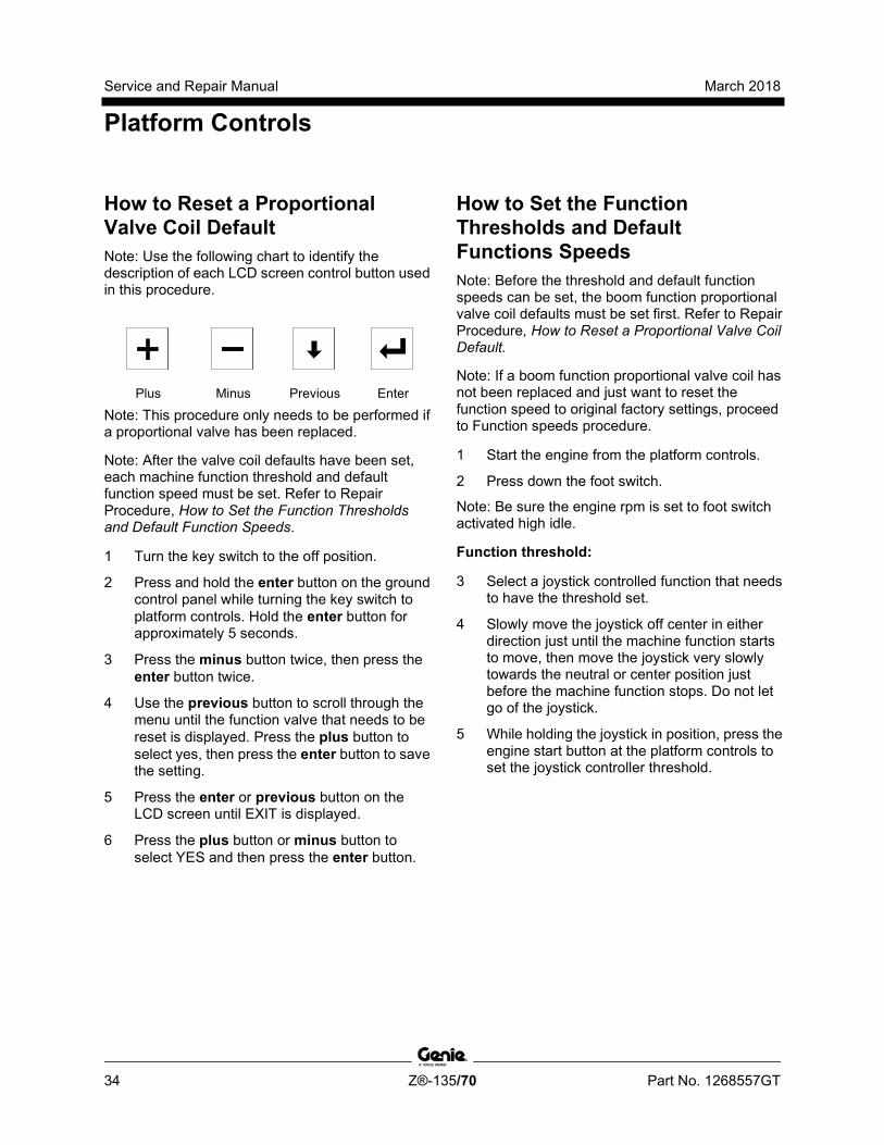
How to Reset a Proportional Valve Coil Default Note: Use the following chart to identify the description of each LCD screen control button used in this procedure.
Plus Minus Previous Enter
Note: This procedure only needs to be performed if a proportional valve has been replaced.
Note: After the valve coil defaults have been set, each machine function threshold and default function speed must be set. Refer to Repair Procedure, How to Set the Function Thresholds and Default Function Speeds.
1 Turn the key switch to the off position.
2 Press and hold the enter button on the ground control panel while turning the key switch to platform controls. Hold the enter button for approximately 5 seconds.
3 Press the minus button twice, then press the enter button twice.
4 Use the previous button to scroll through the menu until the function valve that needs to be reset is displayed. Press the plus button to select yes, then press the enter button to save the setting.
5 Press the enter or previous button on the LCD screen until EXIT is displayed.
6 Press the plus button or minus button to select YES and then press the enter button.
How to Set the Function Thresholds and D efault Func tions Speeds
How to Set the Function Thresholds and Default Functions Speeds Note: Before the threshold and default function speeds can be set, the boom function proportional valve coil defaults must be set first. Refer to Repair Procedure, How to Reset a Proportional Valve Coil Default.
Note: If a boom function proportional valve coil has not been replaced and just want to reset the function speed to original factory settings, proceed to Function speeds procedure.
1 Start the engine from the platform controls.
2 Press down the foot switch.
Note: Be sure the engine rpm is set to foot switch activated high idle.
Function threshold:
3 Select a joystick controlled function that needs to have the threshold set.
4 Slowly move the joystick off center in either direction just until the machine function starts to move, then move the joystick very slowly towards the neutral or center position just before the machine function stops. Do not let go of the joystick.
5 While holding the joystick in position, press the engine start button at the platform controls to set the joystick controller threshold.

March 2018 Service and Repair Manual
Platform Controls
Part No. 1268557GT Z®-135/70 35
6 Slowly move the joystick off center in the opposite direction just until the machine function starts to move, then move the joystick very slowly towards the neutral or center position just before the machine function stops. Do not let go of the joystick.
7 While holding the joystick in position, press the engine start button at the platform controls to set the joystick controller threshold.
8 Repeat steps for each joystick controlled machine function:
• Primary boom up/down
• Turntable rotate left/right
• Primary boom extend/retract
• Secondary up/down and extend/retract
• Drive forward/reverse
9 Once the threshold has been set, press and hold the engine start button until the engine shuts off. Do not press the red Emergency Stop button.
Note: Approximately 3 seconds after the engine shuts off, the alarm at the ground controls will sound to indicate the settings are being saved in memory.
10 At the ground controls, turn the key switch to the off position, wait a moment and then turn the key switch to platform controls.
11 Check the display at the ground controls to be sure there are no calibration faults.
Note: There should be no calibration faults shown on the display. If calibration faults exist, repeat this procedure.
Function speeds:
Note: Be sure the machine is in the stowed position and the boom is rotated between the circle end tires.
Note: Perform this procedure with the machine on a firm, level surface that is free of obstructions.
Note: Unless the LCD screen displays NOT CALIBRATED, it will be necessary to enter the valve calibration menu.
12 Start the engine from the platform controls.
13 Select a function that needs the function speed set.
14 Primary boom up/down and extend/retract functions: Move the joystick full stroke in the up or extend direction. When the alarm sounds, move the joystick in the opposite direction full stroke until the alarm sounds again. Return the joystick to center.
Secondary boom up and down functions: Starting from the stowed position, move the joystick full stroke in the up direction. When the alarm sounds, move the joystick in the down direction full stroke until the alarm sounds again. Return the joystick to center.
Turntable rotate function, fully retracted: Move the rotate joystick full stroke in either the left or right direction until the alarm sounds. Return the joystick to center.

Service and Repair Manual March 2018
Platform Controls
36 Z®-135/70 Part No. 1268557GT
Turntable rotate function, primary boom extended: Extend the primary boom approximately 4 ft / 1.2 m. Move the rotate joystick full stroke in either the left or right direction until the alarm sounds. Return the joystick to center.
Turntable rotate function, primary and jib booms extended: With the primary boom extended approximately 4 ft / 1.2 m, extend the jib boom approximately 1 ft / 0.3 m. Move the rotate joystick full stroke in either the left or right direction until the alarm sounds. Return the joystick to center.
15 Once the function speeds have been set, press and hold the engine start button until the engine shuts off. Do not press the red Emergency Stop button.
Note: Approximately 3 seconds after the engine shuts off, the alarm at the ground controls will sound to indicate the settings are being saved in memory.
16 At the ground controls, turn the key switch to the off position, wait a moment and then turn the key switch to platform controls.
17 Check the display at the ground controls to be sure there are no calibration faults.
Note: There should be no calibration faults shown on the display. If calibration faults exist, repeat this procedure.
How to Adj ust the Functi on Speeds
How to Adjust the Function Speeds Note: Perform this procedure with the boom in the stowed position.
Note: Use the following chart to identify the description of each LCD screen control button used in this procedure.
Plus Minus Previous Enter
1 Pull out the red Emergency Stop button to the on position at both the ground and platform controls.
2 Press and hold the enter button on the ground control panel while turning the key switch to platform controls. Hold the enter button for approximately 5 seconds.
3 Press the plus button twice, then press the minus button twice.
4 Press the previous button until the function to be adjusted is displayed.
5 Press the plus button to increase the speed or press the minus button to decrease the speed.
March 2018 Service and Repair Manual
Platform Controls
Part No. 1268557GT Z®-135/70 37
6 Press the enter button to save the setting in memory.
7 Press the enter or previous button on the LCD screen until EXIT is displayed.
8 Press the plus button or minus button to select YES and then press the enter button.
9 Continue to perform this procedure until the machine function speed meets specification. Refer to Specifications, Performance Specifications.
How to Adj ust the Functi on R amp R ate Setti ng
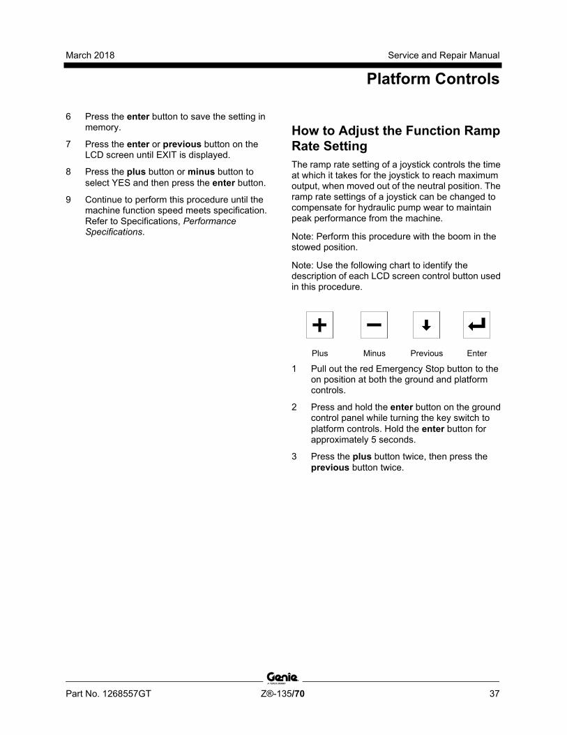
How to Adjust the Function Ramp Rate Setting The ramp rate setting of a joystick controls the time at which it takes for the joystick to reach maximum output, when moved out of the neutral position. The ramp rate settings of a joystick can be changed to compensate for hydraulic pump wear to maintain peak performance from the machine.
Note: Perform this procedure with the boom in the stowed position.
Note: Use the following chart to identify the description of each LCD screen control button used in this procedure.
Plus Minus Previous Enter
1 Pull out the red Emergency Stop button to the on position at both the ground and platform controls.
2 Press and hold the enter button on the ground control panel while turning the key switch to platform controls. Hold the enter button for approximately 5 seconds.
3 Press the plus button twice, then press the previous button twice.
Service and Repair Manual March 2018
Platform Controls
38 Z®-135/70 Part No. 1268557GT
4 Press the previous button until the function to be adjusted is displayed.
5 Press the plus button to increase the ramp rate or press the minus button to decrease the ramp rate.
6 Press the enter button to save the setting in memory.
7 Press the enter or previous button on the LCD screen until EXIT is displayed.
8 Press the plus button or minus button to select YES and then press the enter button.

March 2018 Service and Repair Manual
Platform Components
Part No. 1268557GT Z®-135/70 39
2-1 Platform Leveling Cylinder The platform leveling cylinder keeps the platform level through the entire range of boom motion. The platform is maintained level to the turntable. To accomplish this, the ECM at the ground controls compares the difference in readings between the platform angle sensor and the turntable level sensor, which then sends a signal to the platform controls to open or close the appropriate platform level proportional valve on the platform manifold to maintain a level platform. The platform leveling cylinder is equipped with counterbalance valves to prevent movement in the event of a hydraulic line failure.
How to Remove the Platform Leveling Cylinder Note: When removing a hose assembly or fitting, the O-ring (if equipped) on the fitting and/or hose end must be replaced. All connections must be torqued to specification during installation. Refer to Specifications, Hydraulic Hose and Fitting Torque Specifications.
1 Extend the jib boom until the platform leveling cylinder barrel-end pivot pin is accessible.
2 Raise the jib boom slightly and place blocks under the platform.
3 Lower the jib boom until the platform is resting on the blocks just enough to support the platform.
Note: Do not rest the entire weight of the boom on the blocks.
4 Place a block under the platform leveling cylinder for support.
5 Remove the external snap rings from the barrel-end pivot pin. Use a soft metal drift to remove the barrel-end pivot pin.
6 Support the rod end of the platform level cylinder.
7 Remove the pin retaining fasteners from the platform leveling cylinder rod-end pivot pin. Use a soft metal drift to remove the barrel-end pivot pin.
8 Carefully pull the platform leveling cylinder out of the boom to access the hydraulic hoses.
9 Tag, disconnect and plug the hydraulic hoses from the platform leveling cylinder. Cap the fittings on the cylinder.
Bodily injury hazard. Spraying hydraulic oil can penetrate and burn skin. Loosen hydraulic connections very slowly to allow the oil pressure to dissipate gradually. Do not allow oil to squirt or spray.
10 Remove the platform leveling cylinder from the machine.
Crushing hazard. The platform leveling cylinder may fall if not properly supported when removed from the machine.
Service and Repair Manual March 2018
Platform Components
40 Z®-135/70 Part No. 1268557GT
2-2 Platform Rotator The platform rotator is a hydraulically activated helical gear assembly used to rotate the platform 160 degrees.
How to Remove the Platform Rotator
Component damage hazard. Mark the platform mounting weldment and the rotator flange before removing the platform mounting weldment. The platform mounting weldment must be replaced in the exact same position on the rotator flange as it was before removal. If a new rotator is installed or the rotator is disassembled, proper alignment can be achieved by rotating the rotator all the way to the left and then installing the platform mounting weldment all the way in the left position.
Note: When removing a hose assembly or fitting, the O-ring (if equipped) on the fitting and/or hose end must be replaced. All connections must be torqued to specification during installation. Refer to Specifications, Hydraulic Hose and Fitting Torque Specifications.
1 Remove the platform. Refer to Repair Procedure, How to Remove the Platform.
2 Tag and disconnect the electrical connector from the platform angle sensor.
3 Remove the platform angle sensor retaining fasteners. Remove the platform angle sensor from the platform rotator.
Component damage hazard. The platform angle sensor is a very sensitive instrument. It can be damaged internally if is dropped or sustains any physical shock, even if the damage is not visible.
4 Tag, disconnect and plug the hydraulic hoses from the platform rotator manifold. Cap the fittings on the manifold.
Bodily injury hazard. Spraying hydraulic oil can penetrate and burn skin. Loosen hydraulic connections very slowly to allow the oil pressure to dissipate gradually. Do not allow oil to squirt or spray.
5 Tag, disconnect and plug the hydraulic hoses from the platform manifold. Cap the fittings on the manifold.
Bodily injury hazard. Spraying hydraulic oil can penetrate and burn skin. Loosen hydraulic connections very slowly to allow the oil pressure to dissipate gradually. Do not allow oil to squirt or spray.
6 Remove the power to platform electrical outlet box bracket mounting fasteners. Do not disconnect the wiring.

March 2018 Service and Repair Manual
Platform Components
Part No. 1268557GT Z®-135/70 41
7 Remove the hose and cable guide retaining fasteners and remove the guide from the platform support.
8 Remove the weld cable from the platform (if equipped).
Electrocution/burn hazard. Contact with electrically charged circuits could result in death or serious injury. Remove all rings, watches and other jewelry.
9 Support the platform mounting weldment, but do not apply any lifting pressure.
10 Remove the eight mounting bolts from the platform mounting weldment.
11 Remove the center bolt and slide the platform mounting weldment off of the platform rotator.
Crushing hazard. The platform mounting weldment may become unbalanced and fall if it is not properly supported.
12 Support the platform rotator with a suitable lifting device. Do not apply any lifting pressure.
13 Place a block under the platform leveling cylinder for support.
14 Remove the pin retaining fasteners from the platform leveling cylinder rod-end pivot pin. Do not remove the pin.
15 Remove the pin retaining fasteners from the jib boom to platform rotator pivot pin. Do not remove the pin.
16 Use a soft metal drift to remove both pins and remove the platform rotator from the machine.
Crushing hazard. The platform rotator could fall when removed from the machine if not properly supported.
How to Bleed the Pl atform R otator
How to Bleed the Platform Rotator Note: Do not start the engine. Use auxiliary power for all machine functions in this procedure.
1 Rotate the platform full right, then full left until air is completely out of the rotator. Bleeding the valve is not necessary.

Service and Repair Manual March 2018
Platform Components
42 Z®-135/70 Part No. 1268557GT
2-3 Platform Level Sensor The platform level sensor is mounted to the side of the platform rotator. The platform level sensor is monitored by the control system to maintain a level platform through boom range of motion. If a platform level sensor is replaced, it must be calibrated prior to machine operation.
How to Calibrate the Platform Level Sensor Note: Perform this procedure with the machine on a firm, level surface.
Note: Perform this procedure with the boom in the stowed position.
Note: Use the following chart to identify the description of each LCD screen control button used in this procedure.
Plus Minus Previous Enter
1 Secure a digital level to one of the side railings of the platform.
2 Start the machine and level the platform to gravity. Turn the machine off.
3 Open the ground control box.
Before serial number 321:
4 Locate the 2 pin connector in the lower left hand area of the ground control box.
5 Remove the connector plug and insert a jumper wire between the two pins of the connector.
After serial number 320:
6 Locate the calibration toggle switch at the top of the ground control box. Activate calibration mode by moving the toggle switch in the left direction.
7 Temporarily install a control box door retaining fastener between the door and the box to prevent the control box door from moving the toggle switch while calibrating the machine.
All models:
8 Insert the key into the bypass/recovery key switch and turn it to the bypass position.
Note: The angle sensor calibration values will not be saved correctly unless the key switch is in the bypass position and the calibration toggle switch is activated.
9 Press and hold the enter button on the ground control panel while turning the key switch to ground controls. Hold the enter button for approximately 5 seconds.
10 Enter sensor calibration mode by pressing the buttons at the ground controls in the following sequence: (plus)(enter)(enter)(plus).
March 2018 Service and Repair Manual
Platform Components
Part No. 1268557GT Z®-135/70 43
11 Press the enter or previous button on the LCD screen until SET PLATFORM LEVEL SENSOR TO GRAVITY is displayed.
12 Press the plus button to select YES, then press the enter button to accept.
13 Press the enter or previous button on the LCD screen until EXIT is displayed.
14 Press the plus button to select YES, then press the enter button to accept.
Before serial number 321:
15 Remove the wire jumper from the 2 pin connector in the lower left hand area of the ground control box that was installed in step 5. Install the connector plug.
Tip-over hazard. Failure to remove the jumper wire will result in an unsafe configuration which will compromise machine stability. Operating the machine in this configuration will result in the machine tipping over, resulting in death or serious injury. The jumper wire must be removed before operating the machine.
16 Close the ground control box and install the door retaining fasteners.
After serial number 320:
17 Remove the fastener that was temporarily installed. Close the control box door and install the door retaining fasteners.
Note: When the control box door is closed, the calibration toggle switch is automatically activated to exit out of calibration mode.
2-4 Platform Overload System (if equipped) Proper calibration of the platform overload system is essential to safe machine operation. Continued use of an improperly calibrated platform overload system could result in the system failing to sense an overloaded platform. The stability of the machine is compromised and it could tip over.
How to Calibrate the Platform Overload System (if equipped) Note: Perform this procedure with the machine on a firm, level surface.
1 Level the platform.
2 Determine the maximum platform capacity. Refer to the machine serial plate.
3 Using a suitable lifting device, place an appropriate test weight equal to that of the maximum platform capacity at the center of the platform floor.
Service and Repair Manual March 2018
Platform Components
44 Z®-135/70 Part No. 1268557GT
Determine the limit switch trigger point:
4 Gently move the platform up and down by hand, so it bounces approximately 1 to 2 inches / 2.5 to 5 cm. Allow the platform to settle.
Result: The overload indicator light and the alarm is on. Slowly tighten the load spring adjustment nut by turning it clockwise just until the overload indicator light and alarm turns off.
Note: The platform will need to be moved up and down and allowed to settle in between adjustments.
Note: There may be a 2 second delay before the overload indicator lights flash and the alarm sounds.
Result: The overload indicator light and alarm is off. Slowly loosen the load spring adjustment nut by turning it counterclockwise just until the overload indicator light and alarm turn on.
Note: There may be a 2 second delay before the overload indicator lights flash and the alarm sounds.
Note: The platform will need to be moved up and down and allowed to settle in between adjustments.
Confirm the setting:
5 Start the engine from the platform controls.
6 Lift the test weight off the platform floor using a suitable lifting device.
7 Place the test weight back onto the center of the platform floor using a suitable lifting device.
Result: The alarm should be off. The platform overload indicator light should be off at the platform controls and there should be no error message on the LCD display at the ground controls.
Note: There may be an 2 second delay before the overload indicator lights and alarm turn off.
8 Add an additional 15 lbs / 6.8 kg test weight to the original test weight to overload the platform.
Result: The alarm should be sounding. The platform overload indicator light should be flashing at the platform controls and platform overload should be displayed on the LCD screen at the ground controls.
Note: There may be a 2 second delay before the overload indicator lights flash and the alarm sounds.
March 2018 Service and Repair Manual
Platform Components
Part No. 1268557GT Z®-135/70 45
9 Test all machine functions from the platform controls.
Result: All platform control functions should not operate.
10 Turn the key switch to ground controls.
11 Test all machine functions from the ground controls.
Result: All ground control functions should not operate.
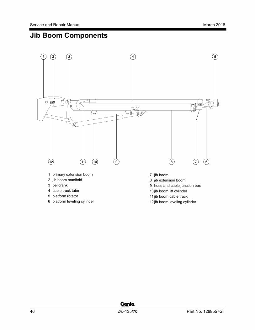
Service and Repair Manual March 2018
Jib Boom Components
46 Z®-135/70 Part No. 1268557GT
1 primary extension boom 2 jib boom manifold 3 bellcrank 4 cable track tube 5 platform rotator 6 platform leveling cylinder
7 jib boom 8 jib extension boom 9 hose and cable junction box 10 jib boom lift cylinder 11 jib boom cable track 12 jib boom leveling cylinder
March 2018 Service and Repair Manual
Jib Boom Components
Part No. 1268557GT Z®-135/70 47
3-1 Jib Boom Cable Track The jib boom cable track guides the cables and hoses running up the jib boom. It can be repaired link by link without removing the cables and hoses that run through it. Removing the entire jib boom cable track is only necessary when performing major repairs that involve removing the jib boom.
How to Remove the Jib Boom Cable Track Note: When removing a hose assembly or fitting, the O-ring (if equipped) on the fitting and/or hose end must be replaced. All connections must be torqued to specification during installation. Refer to Specifications, Hydraulic Hose and Fitting Torque Specifications.
1 Raise the jib boom to a horizontal position. Turn the machine off.
2 Remove the cover from the hose and cable junction box under the jib boom cable track.
3 Tag and disconnect the electrical connectors inside the cable track junction box.
4 Tag, disconnect and plug the two hydraulic hoses from the jib boom manifold that lead to the platform manifold. Cap the fittings on the manifold.
Bodily injury hazard. Spraying hydraulic oil can penetrate and burn skin. Loosen hydraulic connections very slowly to allow the oil pressure to dissipate gradually. Do not allow oil to squirt or spray.
Note: The jib boom manifold is located at the platform end of the primary extension boom.
5 Pull the hoses out of the plastic hose guide located on the primary extension boom near the jib boom manifold.
6 Tag, disconnect and plug the jib boom lift cylinder hydraulic hoses. Cap the fittings on the cylinder.
Bodily injury hazard. Spraying hydraulic oil can penetrate and burn skin. Loosen hydraulic connections very slowly to allow the oil pressure to dissipate gradually. Do not allow oil to squirt or spray.
7 Remove the hose and cable clamp retaining fasteners from the jib boom cable track junction box. Remove the clamps.
8 Pull the jib boom lift cylinder hydraulic hoses out of the jib boom cable track junction box.

Service and Repair Manual March 2018
Jib Boom Components
48 Z®-135/70 Part No. 1268557GT
9 Remove the hose and cable clamp retaining fasteners at the platform end of the jib boom cable track tube. Remove the clamps.
10 Tag and disconnect the electrical connectors from the platform manifold.
11 Tag and disconnect the electrical connectors from the platform box.
12 Tag and disconnect the electrical connector from the foot switch.
13 Tag and disconnect the electrical connector from the platform angle sensor.
14 Tag, disconnect and plug the hydraulic hoses from the "P" and "T" ports on the platform manifold.
15 Pull the two hydraulic hoses just removed and all of the cables through the hose and cable guide at the platform support.
Component damage hazard. Cables and hoses can be damaged if they are kinked or pinched.
16 Remove the cotter pin from the upper cable track tube at the platform end of the jib boom. Do not discard the washer.
Note: Always replace the cotter pin with a new one.
17 Remove the fasteners from the cable track tube guide at the platform end of the jib boom. Remove the cable track tube guide from the jib boom.
18 Place blocks between the upper and lower cable tracks and secure the upper and lower tracks together.
Crushing hazard. If the upper and lower cable tracks are not properly secured together, the cable track could become unbalanced and fall when removed from the machine.
19 Attach a lifting strap from an overhead crane to the cable track.
20 Remove the mounting fasteners that attach the lower cable track to the jib boom.
21 Carefully remove the cable track from the machine and lay it on a structure capable of supporting it.
Crushing hazard. The cable track could become unbalanced and fall if not properly attached to the overhead crane.
Component damage hazard. Cables and hoses can be damaged if they are kinked or pinched.
March 2018 Service and Repair Manual
Jib Boom Components
Part No. 1268557GT Z®-135/70 49
How to R epair the C abl e Tr ack
How to Repair the Cable Track
Component damage hazard. The boom cable track can be damaged if it is twisted.
Note: A cable track repair kit is available through the Genie Service Parts Department.
1 Visually inspect the cable track and determine which 4-link section needs to be replaced.
2 Carefully remove the snap rings and pins from each end of the damaged section of cable track.
3 Remove the retaining fasteners from the upper black rollers from the 4-link section of cable track to be replaced. Remove the rollers.
4 Lift up the hoses and cables and carefully remove the damaged 4-link section of cable track.
Component damage hazard. Cables and hoses can be damaged if they are kinked or pinched.
5 Remove the upper rollers from the replacement section of cable track.
6 Lift up the hoses and cables and carefully insert the new 4-link section of cable track.
Component damage hazard. Cables and hoses can be damaged if they are kinked or pinched.
7 Connect the ends of the replacement cable track section to the existing cable track using the pins and snap rings.
8 Install the rollers onto the new section of cable track.
9 Operate the jib boom extend/retract function through a full cycle to ensure smooth operation of the new section of cable track.
Service and Repair Manual March 2018
Jib Boom Components
50 Z®-135/70 Part No. 1268557GT
3-2 Jib Boom
How to Remove the Jib Boom
Bodily injury hazard. This procedure requires specific repair skills, lifting equipment and a suitable workshop. Attempting this procedure without these skills and tools could result in death or serious injury and significant component damage. Dealer service is strongly recommended.
Note: Perform this procedure with the boom in the stowed position.
Note: When removing a hose assembly or fitting, the O-ring (if equipped) on the fitting and/or hose end must be replaced. All connections must be torqued to specification during installation. Refer to Specifications, Hydraulic Hose and Fitting Torque Specifications.
1 Remove the platform mounting weldment and the platform rotator. Refer to Repair Procedure, How to Remove the Platform Rotator.
2 Tag, disconnect and plug the two hydraulic hoses from the jib boom manifold that lead to the platform manifold. Cap the fittings on the manifold.
Bodily injury hazard. Spraying hydraulic oil can penetrate and burn skin. Loosen hydraulic connections very slowly to allow the oil pressure to dissipate gradually. Do not allow oil to squirt or spray.
3 Tag, disconnect and plug the jib boom lift cylinder hydraulic hoses from the jib boom manifold. Cap the fittings on the manifold.
Bodily injury hazard. Spraying hydraulic oil can penetrate and burn skin. Loosen hydraulic connections very slowly to allow the oil pressure to dissipate gradually. Do not allow oil to squirt or spray.
4 Remove the cotter pin from the upper cable track tube at the platform end of the jib boom.
Note: Always replace the cotter pin with a new one.
5 Remove the cable track guide fasteners from the cable track guide at the platform end of the jib boom and remove the cable track guide from the jib boom.

March 2018 Service and Repair Manual
Jib Boom Components
Part No. 1268557GT Z®-135/70 51
6 Place blocks between the upper and lower cable tracks and secure the upper and lower tracks together.
Crushing hazard. If the upper and lower cable tracks are not properly secured together, the cable track could become unbalanced and fall when removed from the machine.
7 Attach a lifting strap from an overhead crane to the cable track.
8 Remove the mounting fasteners that attach the lower cable track to the jib boom.
9 Remove the cable track from the machine and lay to the side.
Crushing hazard. The cable track could become unbalanced and fall if not properly attached to the overhead crane.
Component damage hazard. Cables and hoses can be damaged if they are kinked or pinched.
10 Disconnect the electrical connector from the jib boom angle sensor located at the jib boom pivot pin on the engine side of the machine.
11 Remove the cover retaining fasteners from the jib boom angle sensor. Remove the cover.
12 Remove the jib boom angle sensor mounting bracket fasteners from the side of the primary extension boom.
13 Carefully remove the bracket and sensor assembly. Note the location of the springs. Do not lose the springs.
Note: There is one spring inside the jib boom pivot pin and one inside the angle sensor.
Note: When the jib boom is installed, the jib boom angle sensor will need to be calibrated. Refer to repair procedure, Jib Boom Bellcrank Angle Sensor for the calibration procedure.
14 Attach a lifting strap from an overhead crane to the platform end of the jib boom.
15 Support the barrel end of the jib boom lift cylinder with another suitable lifting device.
16 Remove the pin retaining fasteners from the jib boom lift cylinder barrel-end pivot pin.
17 Use a soft metal drift to remove the jib boom lift cylinder barrel-end pivot pin.
Crushing hazard. The jib boom could fall when the barrel-end pivot pin is removed if not properly supported by the overhead crane.
Crushing hazard. The jib boom lift cylinder may become unbalanced and fall when it is removed from the machine if it is not properly supported by the overhead crane.
18 Secure the jib boom lift cylinder to the jib boom with a strap or other suitable device.
19 Raise the jib boom to a horizontal position using the overhead crane.
20 Attach a second lifting strap from the overhead crane to the pivot end of the jib boom.
21 Remove the pin retaining fastener from the jib boom pivot pin. Do not remove the pin.
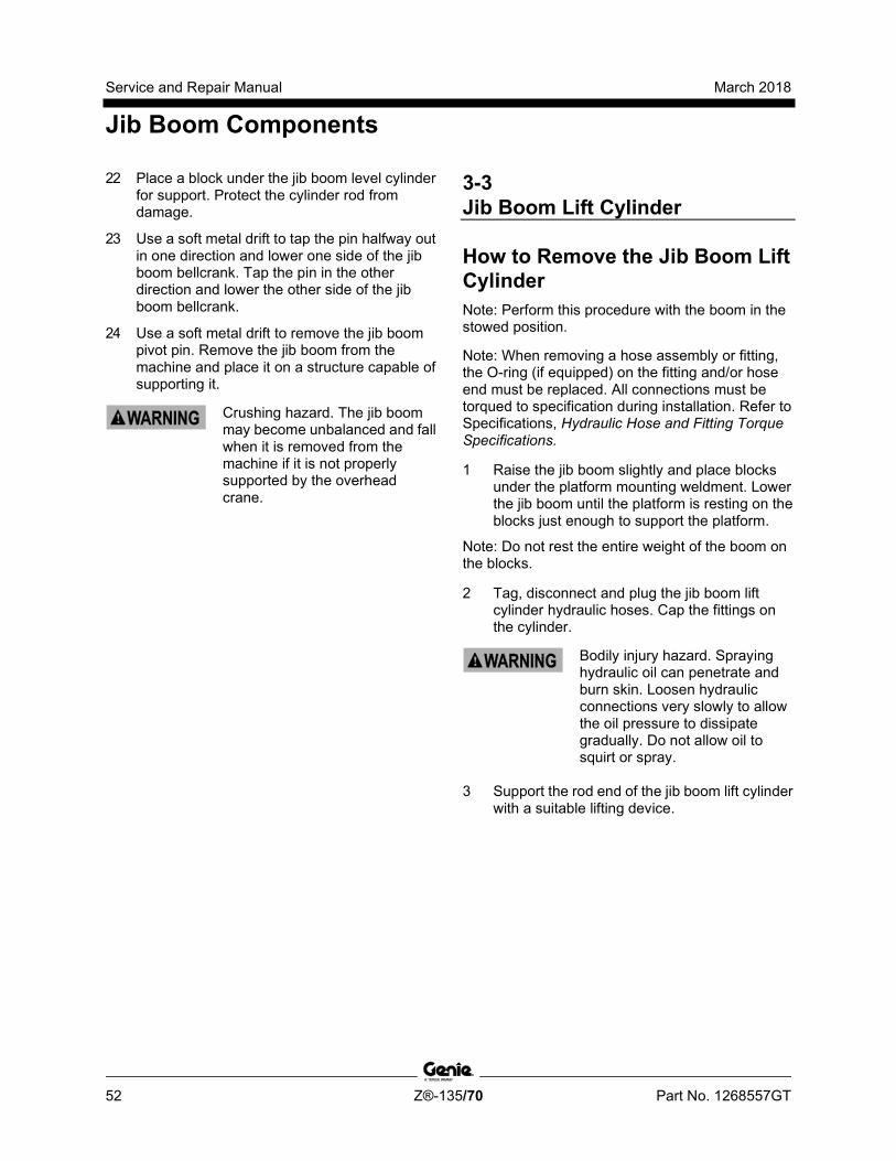
Service and Repair Manual March 2018
Jib Boom Components
52 Z®-135/70 Part No. 1268557GT
22 Place a block under the jib boom level cylinder for support. Protect the cylinder rod from damage.
23 Use a soft metal drift to tap the pin halfway out in one direction and lower one side of the jib boom bellcrank. Tap the pin in the other direction and lower the other side of the jib boom bellcrank.
24 Use a soft metal drift to remove the jib boom pivot pin. Remove the jib boom from the machine and place it on a structure capable of supporting it.
Crushing hazard. The jib boom may become unbalanced and fall when it is removed from the machine if it is not properly supported by the overhead crane.
3-3 Jib Boom Lift Cylinder
How to Remove the Jib Boom Lift Cylinder Note: Perform this procedure with the boom in the stowed position.
Note: When removing a hose assembly or fitting, the O-ring (if equipped) on the fitting and/or hose end must be replaced. All connections must be torqued to specification during installation. Refer to Specifications, Hydraulic Hose and Fitting Torque Specifications.
1 Raise the jib boom slightly and place blocks under the platform mounting weldment. Lower the jib boom until the platform is resting on the blocks just enough to support the platform.
Note: Do not rest the entire weight of the boom on the blocks.
2 Tag, disconnect and plug the jib boom lift cylinder hydraulic hoses. Cap the fittings on the cylinder.
Bodily injury hazard. Spraying hydraulic oil can penetrate and burn skin. Loosen hydraulic connections very slowly to allow the oil pressure to dissipate gradually. Do not allow oil to squirt or spray.
3 Support the rod end of the jib boom lift cylinder with a suitable lifting device.
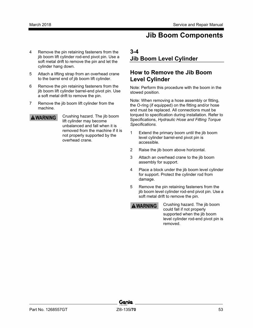
March 2018 Service and Repair Manual
Jib Boom Components
Part No. 1268557GT Z®-135/70 53
4 Remove the pin retaining fasteners from the jib boom lift cylinder rod-end pivot pin. Use a soft metal drift to remove the pin and let the cylinder hang down.
5 Attach a lifting strap from an overhead crane to the barrel end of jib boom lift cylinder.
6 Remove the pin retaining fasteners from the jib boom lift cylinder barrel-end pivot pin. Use a soft metal drift to remove the pin.
7 Remove the jib boom lift cylinder from the machine.
Crushing hazard. The jib boom lift cylinder may become unbalanced and fall when it is removed from the machine if it is not properly supported by the overhead crane.
3-4 Jib Boom Level Cylinder
How to Remove the Jib Boom Level Cylinder Note: Perform this procedure with the boom in the stowed position.
Note: When removing a hose assembly or fitting, the O-ring (if equipped) on the fitting and/or hose end must be replaced. All connections must be torqued to specification during installation. Refer to Specifications, Hydraulic Hose and Fitting Torque Specifications.
1 Extend the primary boom until the jib boom level cylinder barrel-end pivot pin is accessible.
2 Raise the jib boom above horizontal.
3 Attach an overhead crane to the jib boom assembly for support.
4 Place a block under the jib boom level cylinder for support. Protect the cylinder rod from damage.
5 Remove the pin retaining fasteners from the jib boom level cylinder rod-end pivot pin. Use a soft metal drift to remove the pin.
Crushing hazard. The jib boom could fall if not properly supported when the jib boom level cylinder rod-end pivot pin is removed.
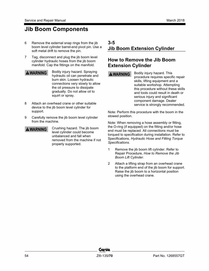
Service and Repair Manual March 2018
Jib Boom Components
54 Z®-135/70 Part No. 1268557GT
6 Remove the external snap rings from the jib boom level cylinder barrel-end pivot pin. Use a soft metal drift to remove the pin.
7 Tag, disconnect and plug the jib boom level cylinder hydraulic hoses from the jib boom manifold. Cap the fittings on the manifold.
Bodily injury hazard. Spraying hydraulic oil can penetrate and burn skin. Loosen hydraulic connections very slowly to allow the oil pressure to dissipate gradually. Do not allow oil to squirt or spray.
8 Attach an overhead crane or other suitable device to the jib boom level cylinder for support.
9 Carefully remove the jib boom level cylinder from the machine.
Crushing hazard. The jib boom level cylinder could become unbalanced and fall when removed from the machine if not properly supported.
3-5 Jib Boom Extension Cylinder
How to Remove the Jib Boom Extension Cylinder
Bodily injury hazard. This procedure requires specific repair skills, lifting equipment and a suitable workshop. Attempting this procedure without these skills and tools could result in death or serious injury and significant component damage. Dealer service is strongly recommended.
Note: Perform this procedure with the boom in the stowed position.
Note: When removing a hose assembly or fitting, the O-ring (if equipped) on the fitting and/or hose end must be replaced. All connections must be torqued to specification during installation. Refer to Specifications, Hydraulic Hose and Fitting Torque Specifications.
1 Remove the jib boom lift cylinder. Refer to Repair Procedure, How to Remove the Jib Boom Lift Cylinder.
2 Attach a lifting strap from an overhead crane to the platform end of the jib boom for support. Raise the jib boom to a horizontal position using the overhead crane.

March 2018 Service and Repair Manual
Jib Boom Components
Part No. 1268557GT Z®-135/70 55
3 Extend the jib boom until the jib boom extension cylinder rod-end pivot pin is accessible.
4 Tag, disconnect and plug the two hydraulic hoses from the jib boom manifold that lead to the platform manifold. Cap the fittings on the manifold.
Bodily injury hazard. Spraying hydraulic oil can penetrate and burn skin. Loosen hydraulic connections very slowly to allow the oil pressure to dissipate gradually. Do not allow oil to squirt or spray.
5 Tag, disconnect and plug the jib boom lift cylinder and jib boom extension cylinder hydraulic hoses from the jib boom manifold. Cap the fittings on the manifold.
Bodily injury hazard. Spraying hydraulic oil can penetrate and burn skin. Loosen hydraulic connections very slowly to allow the oil pressure to dissipate gradually. Do not allow oil to squirt or spray.
6 Remove the cover from the lower jib boom cable track.
7 Tag and disconnect the electrical connectors inside the lower cable track.
8 Remove the hose and cable clamp retaining fasteners from lower cable track at the pivot end of the jib boom. Remove the clamps.
9 Pull the electrical cables out of the lower cable track that lead to the primary boom.
10 Attach a lifting strap from a second overhead crane to the pivot end of the jib boom for support. Do not apply any lifting pressure.
11 Place a block under the jib boom level cylinder for support. Protect the cylinder rod from damage.
12 Remove the pin retaining fastener from the jib boom pivot pin. Do not remove the pin.
13 Use a soft metal drift to tap the pin halfway out in one direction and lower one side of the jib boom bellcrank. Tap the pin in the other direction and lower the other side of the jib boom bellcrank.
14 Use a soft metal drift to remove the jib boom pivot pin. Remove the jib boom from the machine and place it on a structure capable of supporting it.
Crushing hazard. The jib boom may become unbalanced and fall when it is removed from the machine if it is not properly supported by the overhead crane.
15 Remove the pin retaining fasteners from the jib boom extension cylinder rod-end pivot pin. Use a soft metal drift to remove the pin.

Service and Repair Manual March 2018
Jib Boom Components
56 Z®-135/70 Part No. 1268557GT
16 Attach a lifting strap from an overhead crane to the barrel end of the jib boom extension cylinder.
17 Remove the pin retaining fasteners from the jib boom extension cylinder barrel-end pivot pin. Use a soft metal drift to remove the pin.
18 Carefully slide the jib boom extension cylinder out of the jib boom and place it on a structure capable of supporting it.
Crushing hazard. The jib boom extension cylinder could become unbalanced and fall when removed from the jib boom if not properly supported.
Note: During removal, the overhead crane strap will need to be adjusted for proper balancing.
3-6 Jib Boom Bellcrank Angle Sensor The jib boom bellcrank angle sensor is monitored by the control system to keep the jib boom bellcrank vertical and to help maintain a level platform through boom range of motion. If a jib boom bellcrank angle sensor is replaced, it must be calibrated prior to machine operation. The jib boom bellcrank angle sensor is mounted to the bellcrank pivot pin on the engine side of the machine.
How to Replace the Jib Boom Bellcrank Angle Sensor Note: Perform this procedure with the machine on a firm, level surface with the boom in the stowed position.
1 Locate the jib boom bellcrank angle sensor where the jib boom bellcrank connects to the primary boom.
2 Disconnect the electrical connector from the sensor. Remove any tie wraps securing the wiring.
3 Remove the retaining fasteners from the angle sensor guard. Remove the guard from the machine.

March 2018 Service and Repair Manual
Jib Boom Components
Part No. 1268557GT Z®-135/70 57
4 Remove the angle sensor cover retaining fastener. Remove the cover.
5 Remove the angle sensor mounting bracket retaining fasteners.
6 Remove the angle sensor and bracket assembly. Do not lose the two springs or the hex-shaped key.
7 Remove the sensor retaining fasteners from the mounting bracket. Remove the angle sensor.
Note: Note the sensor orientation on the bracket during removal so the new sensor will be installed in the same position.
8 Install the new angle sensor onto the mounting bracket.
9 Install one spring, removed in step 6, into the hex-shaped hole in the angle sensor. Install the other spring into the hex-shaped hole in the center of the boom pivot pin.
10 Insert the hex-shaped key into the angle sensor.
11 Align the side of the sensor with flat area of the boom pivot pin as shown below.
1 flat area 2 angle sensor 3 hex-shaped hole
12 Insert the hex-shaped key into the bellcrank pivot pin allowing free clockwise rotation of the angle sensor mounting bracket.
Note: Be sure the hex-shaped key remains engaged in the sensor.
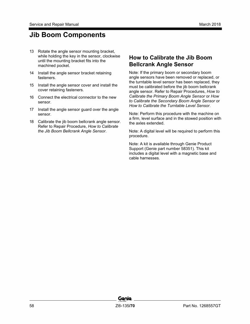
Service and Repair Manual March 2018
Jib Boom Components
58 Z®-135/70 Part No. 1268557GT
13 Rotate the angle sensor mounting bracket, while holding the key in the sensor, clockwise until the mounting bracket fits into the machined pocket.
14 Install the angle sensor bracket retaining fasteners.
15 Install the angle sensor cover and install the cover retaining fasteners.
16 Connect the electrical connector to the new sensor.
17 Install the angle sensor guard over the angle sensor.
18 Calibrate the jib boom bellcrank angle sensor. Refer to Repair Procedure, How to Calibrate the Jib Boom Bellcrank Angle Sensor.
How to C alibr ate the Jib Boom Bellcrank Angl e Sensor
How to Calibrate the Jib Boom Bellcrank Angle Sensor Note: If the primary boom or secondary boom angle sensors have been removed or replaced, or the turntable level sensor has been replaced, they must be calibrated before the jib boom bellcrank angle sensor. Refer to Repair Procedures, How to Calibrate the Primary Boom Angle Sensor or How to Calibrate the Secondary Boom Angle Sensor or How to Calibrate the Turntable Level Sensor.
Note: Perform this procedure with the machine on a firm, level surface and in the stowed position with the axles extended.
Note: A digital level will be required to perform this procedure.
Note: A kit is available through Genie Product Support (Genie part number 58351). This kit includes a digital level with a magnetic base and cable harnesses.
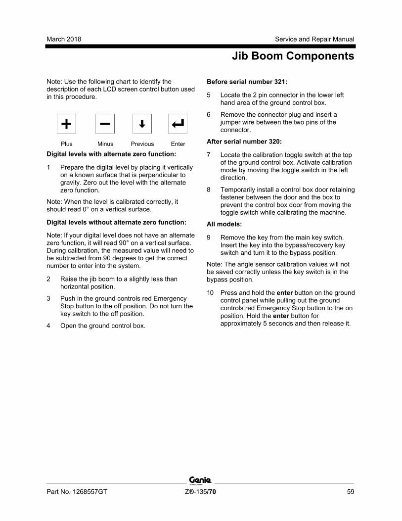
March 2018 Service and Repair Manual
Jib Boom Components
Part No. 1268557GT Z®-135/70 59
Note: Use the following chart to identify the description of each LCD screen control button used in this procedure.
Plus Minus Previous Enter
Digital levels with alternate zero function:
1 Prepare the digital level by placing it vertically on a known surface that is perpendicular to gravity. Zero out the level with the alternate zero function.
Note: When the level is calibrated correctly, it should read 0° on a vertical surface.
Digital levels without alternate zero function:
Note: If your digital level does not have an alternate zero function, it will read 90° on a vertical surface. During calibration, the measured value will need to be subtracted from 90 degrees to get the correct number to enter into the system.
2 Raise the jib boom to a slightly less than horizontal position.
3 Push in the ground controls red Emergency Stop button to the off position. Do not turn the key switch to the off position.
4 Open the ground control box.
Before serial number 321:
5 Locate the 2 pin connector in the lower left hand area of the ground control box.
6 Remove the connector plug and insert a jumper wire between the two pins of the connector.
After serial number 320:
7 Locate the calibration toggle switch at the top of the ground control box. Activate calibration mode by moving the toggle switch in the left direction.
8 Temporarily install a control box door retaining fastener between the door and the box to prevent the control box door from moving the toggle switch while calibrating the machine.
All models:
9 Remove the key from the main key switch. Insert the key into the bypass/recovery key switch and turn it to the bypass position.
Note: The angle sensor calibration values will not be saved correctly unless the key switch is in the bypass position.
10 Press and hold the enter button on the ground control panel while pulling out the ground controls red Emergency Stop button to the on position. Hold the enter button for approximately 5 seconds and then release it.
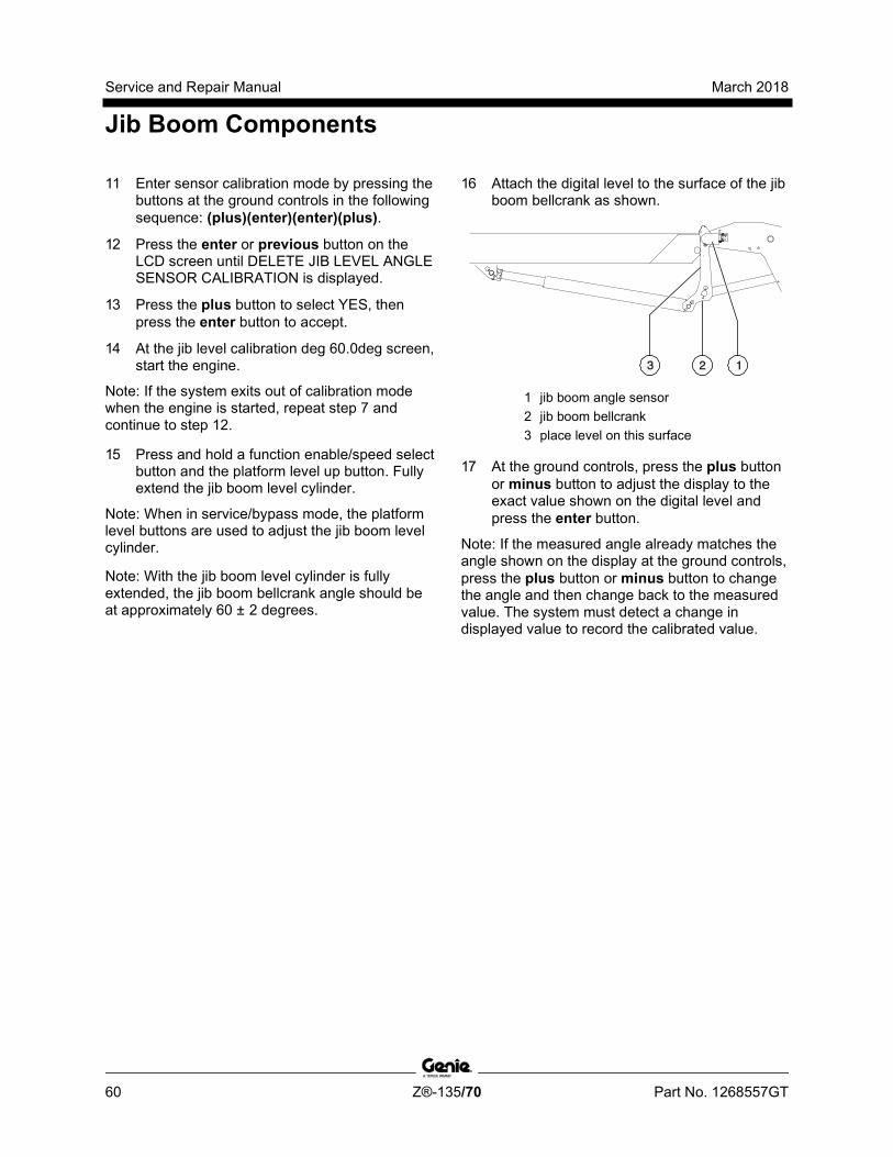
Service and Repair Manual March 2018
Jib Boom Components
60 Z®-135/70 Part No. 1268557GT
11 Enter sensor calibration mode by pressing the buttons at the ground controls in the following sequence: (plus)(enter)(enter)(plus).
12 Press the enter or previous button on the LCD screen until DELETE JIB LEVEL ANGLE SENSOR CALIBRATION is displayed.
13 Press the plus button to select YES, then press the enter button to accept.
14 At the jib level calibration deg 60.0deg screen, start the engine.
Note: If the system exits out of calibration mode when the engine is started, repeat step 7 and continue to step 12.
15 Press and hold a function enable/speed select button and the platform level up button. Fully extend the jib boom level cylinder.
Note: When in service/bypass mode, the platform level buttons are used to adjust the jib boom level cylinder.
Note: With the jib boom level cylinder is fully extended, the jib boom bellcrank angle should be at approximately 60 ± 2 degrees.
16 Attach the digital level to the surface of the jib boom bellcrank as shown.
1 jib boom angle sensor 2 jib boom bellcrank 3 place level on this surface
17 At the ground controls, press the plus button or minus button to adjust the display to the exact value shown on the digital level and press the enter button.
Note: If the measured angle already matches the angle shown on the display at the ground controls, press the plus button or minus button to change the angle and then change back to the measured value. The system must detect a change in displayed value to record the calibrated value.
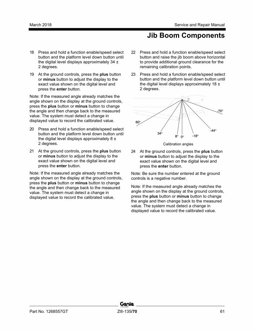
March 2018 Service and Repair Manual
Jib Boom Components
Part No. 1268557GT Z®-135/70 61
18 Press and hold a function enable/speed select button and the platform level down button until the digital level displays approximately 34 ± 2 degrees.
19 At the ground controls, press the plus button or minus button to adjust the display to the exact value shown on the digital level and press the enter button.
Note: If the measured angle already matches the angle shown on the display at the ground controls, press the plus button or minus button to change the angle and then change back to the measured value. The system must detect a change in displayed value to record the calibrated value.
20 Press and hold a function enable/speed select button and the platform level down button until the digital level displays approximately 8 ± 2 degrees.
21 At the ground controls, press the plus button or minus button to adjust the display to the exact value shown on the digital level and press the enter button.
Note: If the measured angle already matches the angle shown on the display at the ground controls, press the plus button or minus button to change the angle and then change back to the measured value. The system must detect a change in displayed value to record the calibrated value.
22 Press and hold a function enable/speed select button and raise the jib boom above horizontal to provide additional ground clearance for the remaining calibration points.
23 Press and hold a function enable/speed select button and the platform level down button until the digital level displays approximately 18 ± 2 degrees.
Calibration angles
24 At the ground controls, press the plus button or minus button to adjust the display to the exact value shown on the digital level and press the enter button.
Note: Be sure the number entered at the ground controls is a negative number.
Note: If the measured angle already matches the angle shown on the display at the ground controls, press the plus button or minus button to change the angle and then change back to the measured value. The system must detect a change in displayed value to record the calibrated value.

Service and Repair Manual March 2018
Jib Boom Components
62 Z®-135/70 Part No. 1268557GT
25 Press and hold a function enable/speed select button and the platform level down button until the digital level displays approximately 44 ± 2 degrees.
26 At the ground controls, press the plus button or minus button to adjust the display to the exact value shown on the digital level and press the enter button.
Note: Be sure the number entered at the ground controls is a negative number.
Note: If the measured angle already matches the angle shown on the display at the ground controls, press the plus button or minus button to change the angle and then change back to the measured value. The system must detect a change in displayed value to record the calibrated value.
27 Press and hold a function enable/speed select button and the platform level down button until the digital level displays approximately 70 ± 2 degrees. The jib boom level cylinder should be fully retracted at this point.
28 At the ground controls, press the plus button or minus button to adjust the display to the exact value shown on the digital level and press the enter button.
Note: Be sure the number entered at the ground controls is a negative number.
Note: If the measured angle already matches the angle shown on the display at the ground controls, press the plus button or minus button to change the angle and then change back to the measured value. The system must detect a change in displayed value to record the calibrated value.
Note: With the jib boom level cylinder fully retracted, the jib boom bellcrank angle should be at approximately 70 degrees.
29 Press and hold the engine start button for approximately 5 seconds to shut off the engine and to save the calibration settings.
Note: Do not turn the engine off with the key switch or red Emergency Stop button or all calibration points or values will not be saved.
30 Press the enter or previous button on the LCD screen until EXIT is displayed.Press the plus button to select YES, then press the enter button to accept.
31 Turn the key back to the run position and remove the key from the bypass/recovery key switch. Insert the key into the main key switch and turn it to ground controls.
Note: Be sure that the bypass/recovery key switch is in the run position before attempting to operate the machine.
32 Wait approximately 20 seconds and turn the machine off by pressing the red Emergency Stop button in.
March 2018 Service and Repair Manual
Jib Boom Components
Part No. 1268557GT Z®-135/70 63
Before serial number 321:
33 Remove the wire jumper from the 2 pin connector in the lower left hand area of the ground control box that was installed in step 6. Install the connector plug.
Tip-over hazard. Failure to remove the jumper wire will result in an unsafe configuration which will compromise machine stability. Operating the machine in this configuration will result in the machine tipping over, resulting in death or serious injury. The jumper wire must be removed before operating the machine.
34 Close the ground control box and install the door retaining fasteners.
After serial number 320:
35 Remove the fastener that was temporarily installed. Close the control box door and install the door retaining fasteners.
Note: When the control box door is closed, the calibration toggle switch is automatically activated to exit out of calibration mode.
All models:
36 Pull out the red Emergency Stop button. Start the engine and lower the boom to the stowed position. Be sure there are no calibration faults shown on the display.
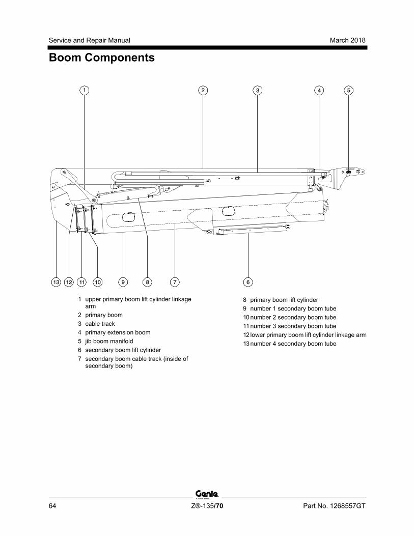
Service and Repair Manual March 2018
Boom Components
64 Z®-135/70 Part No. 1268557GT
1 upper primary boom lift cylinder linkage arm
2 primary boom 3 cable track 4 primary extension boom 5 jib boom manifold 6 secondary boom lift cylinder 7 secondary boom cable track (inside of
secondary boom)
8 primary boom lift cylinder 9 number 1 secondary boom tube 10 number 2 secondary boom tube 11 number 3 secondary boom tube 12 lower primary boom lift cylinder linkage arm 13 number 4 secondary boom tube

March 2018 Service and Repair Manual
Boom Components
Part No. 1268557GT Z®-135/70 65
4-1 Primary Boom Cable Track The primary boom cable track guides the cables and hoses running up the boom. It can be repaired link by link without removing the cables and hoses that run through it. Removing the entire primary boom cable track is only necessary when performing major repairs that involve removing the primary boom.
How to Remove the Primary Boom Cable Track Note: When removing a hose assembly or fitting, the O-ring (if equipped) on the fitting and/or hose end must be replaced. All connections must be torqued to specification during installation. Refer to Specifications, Hydraulic Hose and Fitting Torque Specifications.
Note: Perform this procedure with the machine on a firm, level surface.
Note: Perform this procedure with the boom in the stowed position.
1 Remove the cover from the lower jib boom cable track.
2 Tag and disconnect the electrical connectors inside the lower cable track.
3 Remove the hose and cable clamp retaining fasteners from lower cable track at the pivot end of the jib boom. Remove the clamps.
4 Pull the electrical cables out of the lower cable track that lead to the primary boom.
Component damage hazard. Cables can be damaged if they are kinked or pinched.
5 Tag and disconnect the electrical connectors from the jib boom manifold located at the platform end of the primary extension boom.
6 Tag, disconnect and plug the two hydraulic hoses from the jib boom manifold that lead to the platform manifold. Cap the fittings on the manifold.
Bodily injury hazard. Spraying hydraulic oil can penetrate and burn skin. Loosen hydraulic connections very slowly to allow the oil pressure to dissipate gradually. Do not allow oil to squirt or spray.
7 Remove the retaining fasteners from the hose and cable guide at the platform end of the primary boom. Remove the hose and cable guide.
8 Tag and disconnect the electrical connector from the limit switch on the side of the primary boom. Do not remove the limit switch.
9 Remove the cotter pin from the upper cable track tube at the platform end of the primary extension boom.
Note: Always replace the cotter pin with a new one.

Service and Repair Manual March 2018
Boom Components
66 Z®-135/70 Part No. 1268557GT
10 Remove the retaining fasteners from the cable track guide at the platform end of the boom. Remove the cable track guide from the machine.
11 Place blocks between the upper and lower cable tracks and secure the upper and lower tracks together.
Crushing hazard. If the upper and lower cable tracks are not properly secured together, the cable track could become unbalanced and fall when removed from the machine.
12 Remove the hose and cable clamps from the primary boom lift cylinder.
13 At the counterweight end of the secondary boom, support and secure the secondary boom lower end cover to a suitable lifting device.
14 Remove the cover retaining fasteners and remove the cover from the end of the secondary boom.
Crushing hazard. The secondary boom lower end cover could become unbalanced and fall when removed from the secondary boom if not properly supported and secured to the lifting device.
15 Locate the two hydraulic hoses inside the end of the secondary boom that lead to the primary boom cable track.
16 Tag, disconnect and plug the hydraulic hoses from the unions. Cap the fittings on the unions.
Bodily injury hazard. Spraying hydraulic oil can penetrate and burn skin. Loosen hydraulic connections very slowly to allow the oil pressure to dissipate gradually. Do not allow oil to squirt or spray.
17 Disconnect the electrical connectors for the electrical cables that lead to the cable track at the end of the secondary boom.
18 Pull all hydraulic hoses and electrical cables that lead to the cable track out of the secondary boom riser.
Component damage hazard. Cables and hoses can be damaged if they are kinked or pinched.
19 Attach a lifting strap to each end of the cable track from an overhead crane for support. Do not apply any lifting pressure.
March 2018 Service and Repair Manual
Boom Components
Part No. 1268557GT Z®-135/70 67
20 Remove the mounting fasteners that attach the lower cable track to the primary boom lift cylinder.
21 Remove the mounting fasteners that attach the cable track to the primary boom.
22 Carefully remove the cable track from the machine and lay it on a structure capable of supporting it.
Crushing hazard. The primary boom cable track could become unbalanced and fall when removed from the primary boom if not properly supported by the overhead crane.
Component damage hazard. The boom cable track can be damaged if it is twisted.
Component damage hazard. Cables and hoses can be damaged if they are kinked or pinched.
How to R epair the Primary Boom C abl e Tr ack
How to Repair the Primary Boom Cable Track
Component damage hazard. The boom cable track can be damaged if it is twisted.
Note: A cable track repair kit is available through the Genie Service Parts Department.
1 Visually inspect the cable track and determine which 4-link section needs to be replaced.
2 Support the cable track assembly above the section to be replaced.
3 Carefully remove the snap rings and pins from each end of the damaged section of cable track.
4 Remove the retaining fasteners from the upper black rollers from the 4-link section of cable track to be replaced. Remove the rollers.
5 Lift up the hoses and cables and carefully remove the damaged 4-link section of cable track.
Component damage hazard. Cables and hoses can be damaged if they are kinked or pinched.
Service and Repair Manual March 2018
Boom Components
68 Z®-135/70 Part No. 1268557GT
6 Remove the upper rollers from the replacement section of cable track.
7 Lift up the hoses and cables and carefully insert the new 4-link section of cable track.
Component damage hazard. Cables and hoses can be damaged if they are kinked or pinched.
8 Connect the ends of the replacement cable track section to the existing cable track using the pins and snap rings.
9 Install the rollers onto the new section of cable track.
10 Operate the primary boom extend/retract function through a full cycle to ensure smooth operation of the new section of cable track.
4-2 Secondary Boom Cable Track The secondary boom cable track guides the cables and hoses running up through the inside of the secondary boom. It can be repaired link by link without removing the cables and hoses that run through it. Removal of the secondary boom cable track is required to repair it.
How to Remove the Secondary Boom Cable Track Note: When removing a hose assembly or fitting, the O-ring (if equipped) on the fitting and/or hose end must be replaced. All connections must be torqued to specification during installation. Refer to Specifications, Hydraulic Hose and Fitting Torque Specifications.
1 Working at the counterweight end of the secondary boom, support and secure the secondary boom end cover to a suitable lifting device.
2 Remove the cover retaining fasteners and remove the cover from the secondary boom.
Crushing hazard. The secondary boom end cover could become unbalanced and fall when removed from the secondary boom if not properly supported and secured to the lifting device.
3 Working at the platform end of the secondary boom, support and secure the secondary boom end cover to a suitable lifting device.
March 2018 Service and Repair Manual
Boom Components
Part No. 1268557GT Z®-135/70 69
4 Remove the cover retaining fasteners and remove the cover from the secondary boom.
Crushing hazard. The secondary boom end cover could become unbalanced and fall when removed from the secondary boom if not properly supported and secured to the lifting device.
5 Working at the platform end of the secondary boom, remove the hose and cable U-bolt fasteners near the upper cable track tube.
6 Working at the platform end of the secondary boom, remove the upper cable track tube retaining fasteners. Remove the curved hose guide.
7 Working at the platform end of the secondary boom, remove the lower cable track retaining fasteners.
8 Working at the counterweight end of the secondary boom, remove the lower cable track retaining fasteners.
9 Tag, disconnect and plug the hydraulic hoses from the following ports of the function manifold: PE, PR, P2, T1, PU and PD. Cap the fittings on the manifold.
Bodily injury hazard. Spraying hydraulic oil can penetrate and burn skin. Loosen hydraulic connections very slowly to allow the oil pressure to dissipate gradually. Do not allow oil to squirt or spray.
10 Pull the hydraulic hoses just removed through the turntable bulkhead.
Component damage hazard. Hoses can be damaged if they are kinked or pinched.
11 Working at the counterweight end of the secondary boom, tag, disconnect and plug the hydraulic hoses from the unions that lead to the cable track.
12 Working at the counterweight end of the secondary boom, tag and disconnect the electrical connectors to all of the cables that lead to the secondary boom cable track.
13 Tag, disconnect and plug the primary boom lift cylinder hydraulic hoses. Cap the fittings on the cylinder.
14 Tag, disconnect and plug the primary boom extension cylinder hydraulic hoses at the unions located above the primary boom lift cylinder. Cap the fittings on the unions.
15 Pull the hydraulic hoses for the primary boom lift cylinder and extension cylinder out through the hole in the number 4 secondary boom tube.
Component damage hazard. Hoses can be damaged if they are kinked or pinched.
16 Working at the platform end of the secondary boom, place blocks between the upper and lower cable tracks for support.
Service and Repair Manual March 2018
Boom Components
70 Z®-135/70 Part No. 1268557GT
17 Working at the counterweight end of the secondary boom, attach a lifting strap from an overhead crane to the secondary boom cable track.
18 Carefully pull the secondary boom cable track out of the counterweight end of the boom.
19 Remove the secondary boom cable track from the machine and place it on a structure capable of supporting it.
Crushing hazard. The secondary boom cable track could become unbalanced and fall if not properly supported when removed from the machine.
Component damage hazard. Cables and hoses can be damaged if they are kinked or pinched.
Component damage hazard. The secondary boom cable track can be damaged if it is twisted.
Note: During removal, the overhead crane strap will need to be adjusted for proper balancing.
How to R epair the Secondary Boom C able Tr ack
How to Repair the Secondary Boom Cable Track
Component damage hazard. The boom cable track can be damaged if it is twisted.
Note: A cable track repair kit is available through the Genie Service Parts Department.
1 Remove the secondary boom cable track. Refer to Repair Procedure, How to Remove the Secondary Boom Cable Track.
2 Visually inspect the cable track and determine which 4-link section needs to be replaced.
3 Carefully remove the snap rings and pins from each end of the damaged section of cable track.
4 Remove the retaining fasteners from the upper black rollers from the 4-link section of cable track to be replaced. Remove the rollers.
5 Lift up the hoses and cables and carefully remove the damaged 4-link section of cable track.
Component damage hazard. Cables and hoses can be damaged if they are kinked or pinched.
Note: If the section of cable track being replaced has clamps or wear pads, those items will need to be transferred to the replacement section of cable track.
March 2018 Service and Repair Manual
Boom Components
Part No. 1268557GT Z®-135/70 71
6 Remove the upper rollers from the replacement section of cable track.
7 Lift up the hoses and cables and carefully insert the new 4-link section of cable track.
Component damage hazard. Cables and hoses can be damaged if they are kinked or pinched.
8 Connect the ends of the replacement cable track section to the existing cable track using the pins and snap rings.
9 Install the rollers onto the new section of cable track.
10 Install the secondary boom cable track into the secondary boom.
11 Operate the secondary boom up/extend and down/retract functions through a full cycle to ensure smooth operation of the new section of cable track.
4-3 Primary Boom
How to Remove the Primary Boom
Bodily injury hazard. This procedure requires specific repair skills, lifting equipment and a suitable workshop. Attempting this procedure without these skills and tools could result in death or serious injury and significant component damage. Dealer service is strongly recommended.
Note: When removing a hose assembly or fitting, the O-ring (if equipped) on the fitting and/or hose end must be replaced. All connections must be torqued to specification during installation. Refer to Specifications, Hydraulic Hose and Fitting Torque Specifications.
Note: Perform this procedure with the boom in the stowed position.
1 Remove the platform.
2 Remove the platform mounting weldment and the platform rotator. Refer to Repair Procedure, How to Remove the Platform Rotator.
3 Remove the jib boom. Refer to Repair Procedure, How to Remove the Jib Boom.
Note: When the jib boom is installed, the jib boom angle sensor will need to be calibrated. Refer to Repair Procedure, How to Calibrate the Jib Boom Bellcrank Angle Sensor.

Service and Repair Manual March 2018
Boom Components
72 Z®-135/70 Part No. 1268557GT
4 Remove the primary boom cable track. Refer to repair procedure, How to Remove the Cable Track.
5 Remove the end cover from the pivot end of the primary boom.
6 Remove the limit switch mounting fasteners from the limit switch on the ground controls side of the primary boom. Do not disconnect the wiring. Remove the limit switch.
7 Disconnect the electrical connector from the primary boom angle sensor.
Note: The primary boom angle sensor is located inside the primary boom at the pivot end.
8 Remove the primary boom angle sensor bracket mounting fasteners and remove the primary boom angle sensor from the primary boom. Do not remove the angle sensor from the bracket. Note the location of the springs. Do not lose the springs.
Note: There is one spring inside the primary boom pivot pin and one inside the angle sensor.
Note: When the primary boom is installed, the primary boom angle sensor will need to be calibrated. Refer to Repair Procedure, How to Calibrate the Primary Boom Angle Sensor.
9 Remove the hose and cable guide fasteners at the primary boom pivot pin. Remove the hose and cable guide.
10 Tag, disconnect and plug the primary boom extension cylinder hydraulic hoses. Cap the fittings on the cylinder.
Bodily injury hazard. Spraying hydraulic oil can penetrate and burn skin. Loosen hydraulic connections very slowly to allow the oil pressure to dissipate gradually. Do not allow oil to squirt or spray.
11 Place blocks under both ends of the primary boom lift cylinder for support.
12 Attach a lifting strap from an overhead crane to the rod end of the primary boom lift cylinder.
13 Remove the pin retaining fasteners from the primary boom lift cylinder rod-end pivot pin.
14 Use a soft metal drift to remove the rod-end pivot pin. Rest the rod end of the primary boom lift cylinder on the blocks.
15 Support both upper primary boom lift cylinder linkage arms with a suitable lifting device. Do not apply any lifting pressure.
16 Remove the pin retaining fasteners from the upper primary boom lift cylinder linkage arm pivot pin where it connects to the primary boom.

March 2018 Service and Repair Manual
Boom Components
Part No. 1268557GT Z®-135/70 73
17 Use a soft metal drift to tap the pin halfway out and lower one of the linkage arms down. Tap the pin in the other direction and lower the other linkage arm down.
Crushing hazard. The upper primary boom lift cylinder linkage arms could fall if not properly supported when the pivot pins are removed.
18 Attach a 5 ton / 5000 kg overhead crane to both ends of the primary boom. Do not apply any lifting pressure.
19 Remove the pin retaining fasteners from the primary boom pivot pins.
20 Use a soft metal drift to remove the primary boom pivot pins.
21 Carefully remove the primary boom from the machine and place it on a structure capable of supporting it.
Crushing hazard. The primary boom could become unbalanced and fall when removed from the machine if not properly attached to the overhead crane.
4-4 Primary Boom Lift Cylinder The primary boom lift cylinder raises and lowers the primary boom. The primary boom lift cylinder is equipped with a counterbalance valve to prevent movement in the event of a hydraulic line failure.
How to Remove the Primary Boom Lift Cylinder
Bodily injury hazard. This procedure requires specific repair skills, lifting equipment and a suitable workshop. Attempting this procedure without these skills and tools could result in death or serious injury and significant component damage. Dealer service is strongly recommended.
Note: When removing a hose assembly or fitting, the O-ring (if equipped) on the fitting and/or hose end must be replaced. All connections must be torqued to specification during installation. Refer to Specifications, Hydraulic Hose and Fitting Torque Specifications.
Note: Perform this procedure with the boom in the stowed position.
1 Remove the hose and cable clamps from the primary boom lift cylinder.
2 Remove the cable track retaining fasteners at the primary boom lift cylinder.
3 Place blocks under both ends of the primary boom lift cylinder. Place another block under the cylinder linkage arms under the primary boom lift cylinder barrel-end pivot pin.
Service and Repair Manual March 2018
Boom Components
74 Z®-135/70 Part No. 1268557GT
4 Tag, disconnect and plug the primary boom lift cylinder hydraulic hoses. Cap the fittings on the cylinder.
Bodily injury hazard. Spraying hydraulic oil can penetrate and burn skin. Loosen hydraulic connections very slowly to allow the oil pressure to dissipate gradually. Do not allow oil to squirt or spray.
5 Attach a lifting strap from an overhead crane to the rod end of the primary boom lift cylinder. Do not apply any lifting pressure.
6 Remove the pin retaining fasteners from the primary boom lift cylinder rod-end pivot pin. Use a soft metal drift to remove the pin and rest the cylinder on the block.
7 Attach a lifting strap from a second overhead crane to the barrel end of the primary boom lift cylinder. Do not apply any lifting pressure.
8 Remove the primary boom lift cylinder barrel-end pivot pin retaining fasteners.
9 Use a soft metal drift to remove the barrel-end pivot pin. Carefully remove the primary boom lift cylinder from the machine.
Crushing hazard. The boom lift cylinder may become unbalanced and fall if it is not properly supported when it is removed from the machine.
Crushing hazard. The primary boom lift cylinder linkage arms may fall if not properly supported when the barrel-end pivot pin is removed.
4-5 Secondary Boom Lift Cylinder
How to Remove the Secondary Boom Lift Cylinder
Bodily injury hazard. This procedure requires specific repair skills, lifting equipment and a suitable workshop. Attempting this procedure without these skills and tools could result in death or serious injury and significant component damage. Dealer service is strongly recommended.
Note: When removing a hose assembly or fitting, the O-ring (if equipped) on the fitting and/or hose end must be replaced. All connections must be torqued to specification during installation. Refer to Specifications, Hydraulic Hose and Fitting Torque Specifications.
Note: Perform this procedure with the machine on a firm, level surface and in the stowed position with the axles extended.
1 Tag, disconnect and plug the hydraulic hoses from the secondary boom lift cylinder. The hoses can be accessed from under the turntable.
Bodily injury hazard. Spraying hydraulic oil can penetrate and burn skin. Loosen hydraulic connections very slowly to allow the oil pressure to dissipate gradually. Do not allow oil to squirt or spray.
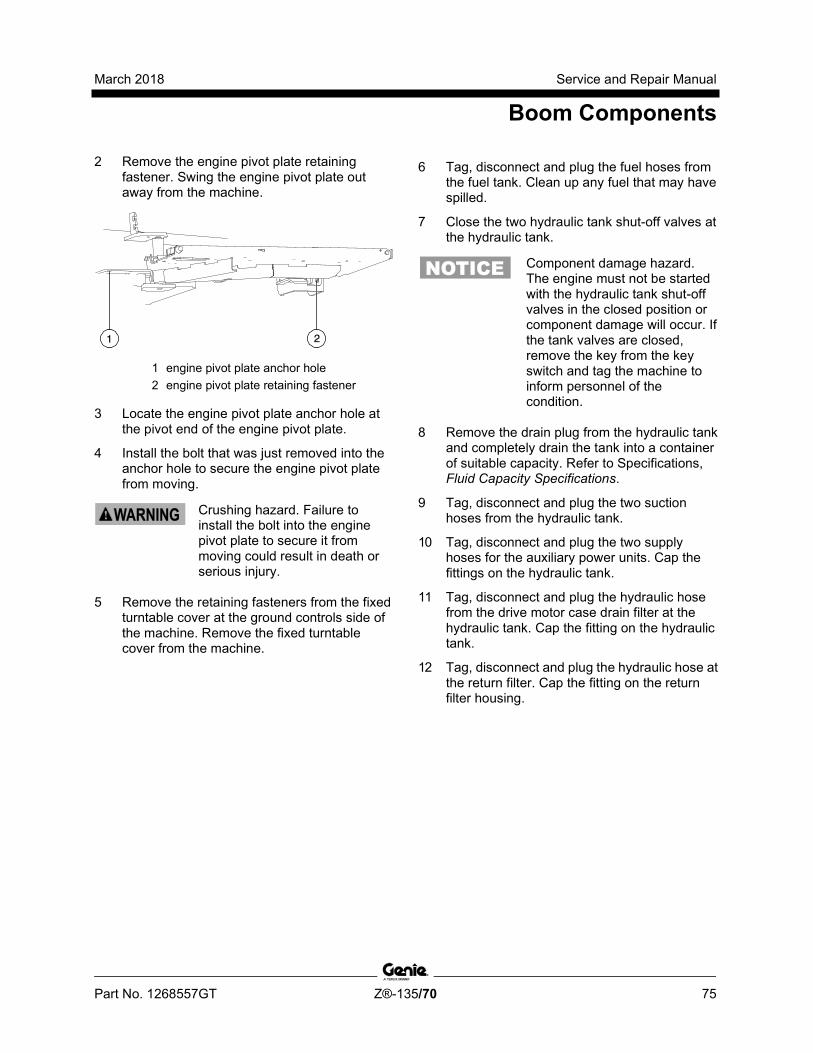
March 2018 Service and Repair Manual
Boom Components
Part No. 1268557GT Z®-135/70 75
2 Remove the engine pivot plate retaining fastener. Swing the engine pivot plate out away from the machine.
1 engine pivot plate anchor hole 2 engine pivot plate retaining fastener
3 Locate the engine pivot plate anchor hole at the pivot end of the engine pivot plate.
4 Install the bolt that was just removed into the anchor hole to secure the engine pivot plate from moving.
Crushing hazard. Failure to install the bolt into the engine pivot plate to secure it from moving could result in death or serious injury.
5 Remove the retaining fasteners from the fixed turntable cover at the ground controls side of the machine. Remove the fixed turntable cover from the machine.
6 Tag, disconnect and plug the fuel hoses from the fuel tank. Clean up any fuel that may have spilled.
7 Close the two hydraulic tank shut-off valves at the hydraulic tank.
Component damage hazard. The engine must not be started with the hydraulic tank shut-off valves in the closed position or component damage will occur. If the tank valves are closed, remove the key from the key switch and tag the machine to inform personnel of the condition.
8 Remove the drain plug from the hydraulic tank and completely drain the tank into a container of suitable capacity. Refer to Specifications, Fluid Capacity Specifications.
9 Tag, disconnect and plug the two suction hoses from the hydraulic tank.
10 Tag, disconnect and plug the two supply hoses for the auxiliary power units. Cap the fittings on the hydraulic tank.
11 Tag, disconnect and plug the hydraulic hose from the drive motor case drain filter at the hydraulic tank. Cap the fitting on the hydraulic tank.
12 Tag, disconnect and plug the hydraulic hose at the return filter. Cap the fitting on the return filter housing.
Service and Repair Manual March 2018
Boom Components
76 Z®-135/70 Part No. 1268557GT
13 Remove the turntable cover using a suitable lifting device.
Crushing hazard. The turntable cover may become unbalanced and fall if not properly supported and secured to a suitable lifting device.
14 Remove the ground control box mounting fasteners. Move the ground control box out of the way.
15 Remove the hydraulic tank retaining fasteners.
16 Remove the cover from the auxiliary power unit batteries.
17 Tag and disconnect the cables from the auxiliary power unit batteries.
Electrocution/burn hazard. Contact with electrically charged circuits could result in death or serious injury. Remove all rings, watches and other jewelry.
18 Tag and disconnect the cables from the engine starting/controls battery located on the engine side of the machine.
Electrocution/burn hazard. Contact with electrically charged circuits could result in death or serious injury. Remove all rings, watches and other jewelry.
19 Attach an overhead crane or similar lifting device to the battery box for the auxiliary power unit batteries.
20 Remove the battery box retaining fasteners and carefully remove the battery box from the machine.
Crushing hazard. The battery box could become unbalanced and fall when removed from the machine if not properly supported.
Bodily injury hazard. Batteries contain acid. Avoid spilling or contacting battery acid. Neutralize battery acid spills with baking soda and water.
21 Support the hydraulic tank with 2 lifting straps. Place one lifting strap at each end of the tank and attach the lifting straps to an appropriate lifting device.
22 Remove the hydraulic tank from the machine.
Crushing hazard. The hydraulic tank could become unbalanced and fall if not properly supported when removed from the machine.
23 Place a block under the secondary boom lift cylinder for support.
March 2018 Service and Repair Manual
Boom Components
Part No. 1268557GT Z®-135/70 77
24 Remove the secondary boom lift cylinder rod-end pivot pin retaining fasteners. Use a soft metal drift to remove the pin through the access holes in the turntable bulkheads.
25 Attach an overhead crane with a minimum capacity of 7 tons / 7000 kg to the counterweight end of the secondary boom.
26 Raise the boom assembly with the overhead crane approximately 20 feet / 6 m.
Crushing hazard. The boom assembly can fall if not properly supported by the overhead crane.
27 Remove the secondary boom lift cylinder barrel-end pivot pin retaining fasteners. Do not remove the pin.
28 Attach a lifting strap from a second overhead crane to each end of the secondary boom lift cylinder.
Note: Protect the hoses and cables underneath the cylinder from damage.
29 Use a slide hammer to remove the barrel-end pivot pin.
Component damage hazard. Hoses and cables can become damaged if the barrel end of the secondary boom lift cylinder is allowed to fall when the barrel-end pivot pin is removed.
30 Carefully remove the secondary boom lift cylinder from the machine.
Crushing hazard. The secondary boom lift cylinder could become unbalanced and fall when removed from the machine if not properly attached to the overhead crane.
Component damage hazard. Hoses and cables can be damaged if the secondary boom lift cylinder is pulled across them.
Service and Repair Manual March 2018
Boom Components
78 Z®-135/70 Part No. 1268557GT
4-6 Primary Boom Extension Cylinder The primary boom extension cylinder extends and retracts the primary boom extension tube.The primary boom extension cylinder is equipped with counterbalance valves to prevent movement in the event of a hydraulic line failure.
How to Remove the Primary Boom Extension Cylinder
Bodily injury hazard. This procedure requires specific repair skills, lifting equipment and a suitable workshop. Attempting this procedure without these skills and tools could result in death or serious injury and significant component damage. Dealer service is strongly recommended.
Note: When removing a hose assembly or fitting, the O-ring (if equipped) on the fitting and/or hose end must be replaced. All connections must be torqued to specification during installation. Refer to Specifications, Hydraulic Hose and Fitting Torque Specifications.
Note: Perform this procedure with the machine on a firm, level surface and in the stowed position with the axles extended.
1 Extend the primary boom until the primary boom extension cylinder rod-end pivot pin is accessible in the primary boom extension tube.
2 Remove the access cover from the pivot end of the primary boom.
3 Tag, disconnect and plug the primary boom extension cylinder hydraulic hoses. Cap the fittings on the cylinder.
Bodily injury hazard. Spraying hydraulic oil can penetrate and burn skin. Loosen hydraulic connections very slowly to allow the oil pressure to dissipate gradually. Do not allow oil to squirt or spray.
4 At the platform end, remove the external snap rings from the extension cylinder rod-end pivot pin. Use a soft metal drift to remove the pin.
5 Remove the extension cylinder retainers from the saddle blocks.
6 Attach a lifting strap from an overhead crane to the barrel end of the primary boom extension cylinder.
7 Using the overhead crane, lift the extension cylinder to clear the saddle blocks.
8 Support and slide the primary boom extension cylinder out of the primary boom and place it on a structure capable of supporting it.
Crushing hazard. The extension cylinder could become unbalanced and fall when removed from primary boom extension tube if not properly supported.
Note: During removal, the overhead crane strap will need to be adjusted for proper balancing.
Note: Note the length of the cylinder after removal. The cylinder must be at the same length for installation.

March 2018 Service and Repair Manual
Boom Components
Part No. 1268557GT Z®-135/70 79
4-7 Secondary Boom Extension Cylinders The secondary boom extension cylinders extend and retract the secondary boom. The secondary boom extension system consists of 3 hydraulic cylinders and each are equipped with counterbalance valves to prevent movement in the event of a hydraulic line failure.
How to Remove the Secondary Boom Extension Cylinders
Bodily injury hazard. This procedure requires specific repair skills, lifting equipment and a suitable workshop. Attempting this procedure without these skills and tools could result in death or serious injury and significant component damage. Dealer service is strongly recommended.
Note: When removing a hose assembly or fitting, the O-ring (if equipped) on the fitting and/or hose end must be replaced. All connections must be torqued to specification during installation. Refer to Specifications, Hydraulic Hose and Fitting Torque Specifications.
Note: Perform this procedure with the machine on a firm, level surface and in the stowed position with the axles extended.
1 Raise the primary boom approximately 10 feet / 3 m. Turn the machine off.
2 Working at the platform end of the secondary boom, support and secure the secondary boom end cover to a suitable lifting device.
3 Remove the cover retaining fasteners and remove the cover from the secondary boom.
Crushing hazard. The secondary boom end cover could become unbalanced and fall when removed from the secondary boom if not properly supported and secured to the lifting device.
4 Remove the retaining fasteners from both secondary boom extend limit switches and remove the limit switches. Do not disconnect the wiring.
Note: Label the location of each limit switch as they are not the same and their mounting locations cannot be exchanged.
5 Tag, disconnect and plug all hydraulic hoses for the 3 secondary boom extension cylinders. Cap the fittings on the cylinder.
Bodily injury hazard. Spraying hydraulic oil can penetrate and burn skin. Loosen hydraulic connections very slowly to allow the oil pressure to dissipate gradually. Do not allow oil to squirt or spray.
6 Remove the upper extension cylinder retainers from the saddle blocks.

Service and Repair Manual March 2018
Boom Components
80 Z®-135/70 Part No. 1268557GT
7 Attach a lifting strap from an overhead crane to the rod end of the upper extension cylinder.
8 Using the overhead crane, lift the extension cylinder to clear the saddle blocks.
9 Support and slide the upper extension cylinder out of the secondary boom and place it on a structure capable of supporting it.
Crushing hazard. The extension cylinder could fall when removed from the secondary boom if not properly supported.
Note: During removal, the overhead crane strap will need to be adjusted for proper balancing.
10 Repeat steps 6 through 9 for the remaining secondary boom extension cylinders.
Note: The secondary boom extension cylinders must be installed in the same order they were removed.
Note: When installing the middle and upper secondary boom extension cylinders, be sure the grooved wear pads are correctly aligned with the channels on the top of the cylinders.
1 upper extension cylinder (#1) 2 middle extension cylinder (#2) 3 bottom extension cylinder (#3) 4 cylinder grooved wear pads 5 channels

March 2018 Service and Repair Manual
Boom Components
Part No. 1268557GT Z®-135/70 81
4-8 Primary Boom Angle Sensor The primary boom angle sensor is used to limit the angle of the primary boom relative to the angle of the secondary boom and gravity.
How to Replace the Primary Boom Angle Sensor Note: Perform this procedure with the machine on a firm, level surface with the boom in the stowed position.
1 Remove the retaining fasteners from the boom end cover at the pivot end of the primary boom. Remove the cover from the machine.
2 Locate the primary boom angle sensor inside the primary boom at the boom pivot pin.
3 Disconnect the electrical connector from the sensor.
4 Remove the angle sensor mounting bracket retaining fasteners.
5 Remove the angle sensor and bracket assembly. Do not lose the two springs or the hex-shaped key.
6 Remove the sensor retaining fasteners from the mounting bracket. Remove the angle sensor.
Note: Note the sensor orientation on the bracket during removal so the new sensor will be installed in the same position.
7 Install the new angle sensor onto the mounting bracket.
8 Install one spring, removed in step 5, into the hex-shaped hole in the angle sensor. Install the other spring into the hex-shaped hole in the center of the boom pivot pin.
9 Insert the hex-shaped key into the angle sensor.
10 Align the side of the sensor with flat area of the boom pivot pin as shown below while holding the bracket away from key insertion.
1 flat area 2 angle sensor 3 hex-shaped hole
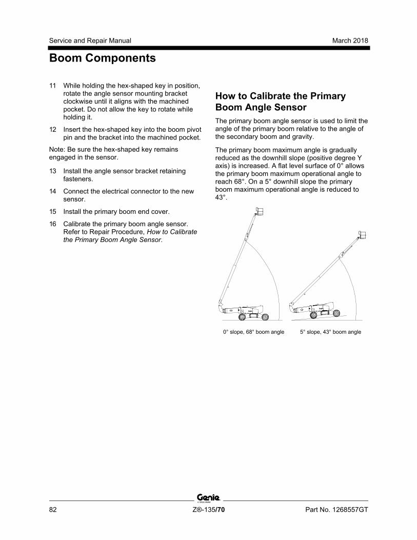
Service and Repair Manual March 2018
Boom Components
82 Z®-135/70 Part No. 1268557GT
11 While holding the hex-shaped key in position, rotate the angle sensor mounting bracket clockwise until it aligns with the machined pocket. Do not allow the key to rotate while holding it.
12 Insert the hex-shaped key into the boom pivot pin and the bracket into the machined pocket.
Note: Be sure the hex-shaped key remains engaged in the sensor.
13 Install the angle sensor bracket retaining fasteners.
14 Connect the electrical connector to the new sensor.
15 Install the primary boom end cover.
16 Calibrate the primary boom angle sensor. Refer to Repair Procedure, How to Calibrate the Primary Boom Angle Sensor.
How to C alibr ate the Prim ary Boom Angle Sensor
How to Calibrate the Primary Boom Angle Sensor The primary boom angle sensor is used to limit the angle of the primary boom relative to the angle of the secondary boom and gravity.
The primary boom maximum angle is gradually reduced as the downhill slope (positive degree Y axis) is increased. A flat level surface of 0° allows the primary boom maximum operational angle to reach 68°. On a 5° downhill slope the primary boom maximum operational angle is reduced to 43°.
0° slope, 68° boom angle 5° slope, 43° boom angle

March 2018 Service and Repair Manual
Boom Components
Part No. 1268557GT Z®-135/70 83
Note: If the axle sensor or secondary boom angle sensor have been removed or replaced, or the turntable level sensor has been replaced, they must be calibrated first. Refer to Repair Procedures, How to Calibrate the Axle Angle Sensors or How to Calibrate the Secondary Boom Angle Sensor or How to Calibrate the Turntable Level Sensor.
Tip-over hazard. Failure to properly calibrate the machine could cause the machine to tip over resulting in death or serious injury.
Note: For software versions 4.01 and higher, use the 2 Point Calibration procedure. For software versions before 4.01, use the 6 Point Calibration procedure. The software version is displayed on the LCD screen when the red Emergency Stop button is pulled out to the on position.
Note: A digital level will only be required to perform the 6 Point Calibration procedure.
Note: A kit is available through Genie Product Support (Genie part number 58351). This kit includes a digital level with a magnetic base and cable harnesses.
Note: Use the following chart to identify the description of each LCD screen control button used in this procedure.
Plus Minus Previous Enter
Note: Perform this procedure with the machine on a firm, level surface with the booms in the fully stowed position, in the drive enable zone and the axles fully extended.
6 Point Calibration procedure
Note: Use this procedure for software versions before 4.01.
Note: For the 2 Point Calibration procedure, proceed to step 37.
1 Push in the ground controls red Emergency Stop button to the off position. Do not turn the key switch to the off position.
2 Turn the key switch to ground controls.
3 Open the ground control box.
Before serial number 321:
4 Locate the 2 pin connector in the lower left hand area of the ground control box.
5 Remove the connector plug and insert a jumper wire between the two pins of the connector.
After serial number 320:
6 Locate the calibration toggle switch at the top of the ground control box. Activate calibration mode by moving the toggle switch in the left direction.
7 Temporarily install a control box door retaining fastener between the door and the box to prevent the control box door from moving the toggle switch while calibrating the machine.
All models:
8 Remove the key from the main key switch. Insert the key into the bypass/recovery key switch and turn it to the bypass position.
Note: The angle sensor calibration values will not be saved correctly unless the key switch is in the bypass position and the calibration toggle switch is activated.

Service and Repair Manual March 2018
Boom Components
84 Z®-135/70 Part No. 1268557GT
9 Press and hold the enter button on the ground control panel while pulling out the ground controls red Emergency Stop button to the on position. Hold the enter button for approximately 5 seconds and then release it.
10 Enter sensor calibration mode by pressing the buttons at the ground controls in the following sequence: (plus)(enter)(enter)(plus).
11 Press the enter or previous button on the LCD screen until DELETE PRIMARY BOOM ANGLE SENSOR CALIBRATION is displayed.
12 Press the plus button to select YES, then press the enter button to accept.
13 Place a digital level that has been calibrated to gravity on top of the primary boom and note the angle displayed on the digital level.
14 At the PRIMARY BOOM ANGLE TO GRAVITY 0.0 DEG screen, press the plus button or minus button to adjust the display to the exact value shown on the digital level, then press the enter button.
Note: If the measured angle already matches the angle shown on the display at the ground controls, press the plus button or minus button to change the angle and then change back to the measured value. The system must detect a change in displayed value to record the calibrated value.
15 Start the engine from the ground controls.
Note: If the system exits out of calibration mode when the engine is started, repeat step 8 and then continue with step 14.
16 Fully raise the secondary boom. The boom is fully raised when the cylinder is fully extended and the boom stops moving.
17 Press and hold a function enable/speed select button and the primary boom down button and lower the primary boom down until the digital level displays -50 degrees.
18 At the ground controls, press the plus button or minus button to adjust the display to the exact value shown on the digital level and press the enter button.
Note: Be sure the number entered at the ground controls is a negative number.
Note: If the measured angle already matches the angle shown on the display at the ground controls, press the plus button or minus button to change the angle and then change back to the measured value. The system must detect a change in displayed value to record the calibrated value.
19 Press and hold a function enable/speed select button and the primary boom up button until the digital level displays -20 degrees.
20 At the ground controls, press the plus button or minus button to adjust the display to the exact value shown on the digital level and press the enter button.
Note: Be sure the number entered at the ground controls is a negative number.
Note: If the measured angle already matches the angle shown on the display at the ground controls, press the plus button or minus button to change the angle and then change back to the measured value. The system must detect a change in displayed value to record the calibrated value.
21 Press and hold a function enable/speed select button and the primary boom up button until the digital level displays 10 degrees.
March 2018 Service and Repair Manual
Boom Components
Part No. 1268557GT Z®-135/70 85
22 At the ground controls, press the plus button or minus button to adjust the display to the exact value shown on the digital level and press the enter button.
Note: If the measured angle already matches the angle shown on the display at the ground controls, press the plus button or minus button to change the angle and then change back to the measured value. The system must detect a change in displayed value to record the calibrated value.
23 Press and hold a function enable/speed select button and the primary boom up button until the digital level displays 40 degrees.
24 At the ground controls, press the plus button or minus button to adjust the display to the exact value shown on the digital level and press the enter button.
Note: If the measured angle already matches the angle shown on the display at the ground controls, press the plus button or minus button to change the angle and then change back to the measured value. The system must detect a change in displayed value to record the calibrated value.
25 Press and hold a function enable/speed select button and the primary boom up button until the primary boom is fully raised. The boom is fully raised when the cylinder is fully extended and the boom stops moving. The angle will be 70 degrees.
26 At the ground controls, press the plus button or minus button to adjust the display to the exact value shown on the digital level and press the enter button.
Note: If the measured angle already matches the angle shown on the display at the ground controls, press the plus button or minus button to change the angle and then change back to the measured value. The system must detect a change in displayed value to record the calibrated value.
27 Press and hold the engine start button for approximately 5 seconds to shut off the engine and to save the calibration settings.
Note: Do not turn the engine off with the key switch or red Emergency Stop button or all calibration points or values will not be saved.
28 Press the enter or previous button on the LCD screen until EXIT is displayed.
29 Press the plus button to select YES, then press the enter button to accept.
30 Turn the key back to the run position and remove the key from the bypass/recovery key switch. Insert the key into the main key switch and turn it to ground controls.
Note: Be sure that the bypass/recovery key switch is in the run position before attempting to operate the machine.
31 Wait approximately 20 seconds and turn the machine off by pressing the red Emergency Stop button in.
Before serial number 321
32 Remove the wire jumper from the 2 pin connector in the lower left hand area of the ground control box that was installed in step 5. Install the connector plug.
Tip-over hazard. Failure to remove the jumper wire will result in an unsafe configuration which will compromise machine stability. Operating the machine in this configuration will result in the machine tipping over, resulting in death or serious injury. The jumper wire must be removed before operating the machine.
33 Close the ground control box and install the door retaining fasteners.

Service and Repair Manual March 2018
Boom Components
86 Z®-135/70 Part No. 1268557GT
After serial number 320:
34 Remove the fastener that was temporarily installed. Close the control box door and install the door retaining fasteners.
Note: When the control box door is closed, the calibration toggle switch is automatically activated to exit out of calibration mode.
All models:
35 Pull out the red Emergency Stop button. Start the engine and lower the boom to the stowed position. Be sure there are no calibration faults shown on the display.
36 Perform a primary boom angle test. Refer to Maintenance Procedure in the appropriate Service or Maintenance Manual, Test the Primary Boom Angle Sensor.
2 Point Calibration procedure
Note: Use this procedure for software versions 4.01 and higher.
37 Push in the ground controls red Emergency Stop button to the off position. Do not turn the key switch to the off position.
38 Turn the key switch to ground controls.
39 Open the ground control box.
40 Locate the calibration toggle switch at the top of the ground control box. Activate calibration mode by moving the toggle switch in the left direction.
41 Temporarily install a control box door retaining fastener between the door and the box to prevent the control box door from moving the toggle switch while calibrating the machine.
42 Remove the key from the main key switch. Insert the key into the bypass/recovery key switch and turn it to the bypass position.
43 Note: The angle sensor calibration values will not be saved correctly unless the key switch is in the bypass position and the calibration toggle switch is activated.
44 Press and hold the enter button on the ground control panel while pulling out the ground controls red Emergency Stop button to the on position. Hold the enter button for approximately 5 seconds and then release it.
45 Enter sensor calibration mode by pressing the buttons at the ground controls in the following sequence: (plus)(enter)(enter)(plus).
46 Press the enter or previous button on the LCD screen until DELETE PRIMARY BOOM ANGLE SENSOR CALIBRATION is displayed.

March 2018 Service and Repair Manual
Boom Components
Part No. 1268557GT Z®-135/70 87
47 Press the plus button to select YES, then press the enter button to accept.
48 Lower the primary boom to the stowed position.
49 Press the enter or previous button on the LCD SCREEN UNTIL PRIMARY BOOM FULLY LOWERED is displayed.
50 Press the plus button to select YES, then press the enter button to accept.
51 Fully raise the secondary boom until it stops at the end of the cylinder stroke.
52 Fully raise the primary boom until it stops at the end of the cylinder stroke.
53 Press the enter or previous button on the LCD screen until PRIMARY BOOM FULLY RAISED is displayed.
54 Press the plus button to select YES, then press the enter button to accept.
55 Press and hold the engine start button for approximately 5 seconds to shut off the engine and to save the calibration settings.
Note: Do not turn the engine off with the key switch or red Emergency Stop button or all calibration points or values will not be saved.
56 Press the enter or previous button on the LCD screen until EXIT is displayed.
57 Press the plus button to select YES, then press the enter button to accept.
58 Turn the key back to the run position and remove the key from the bypass/recovery key switch. Insert the key into the main key switch and turn it to ground controls.
Note: Be sure that the bypass/recovery key switch is in the run position before attempting to operate the machine.
59 Wait approximately 20 seconds and turn the machine off by pressing the red Emergency Stop button in.
60 Remove the fastener that was temporarily installed. Close the control box door and install the door retaining fasteners.
Note: When the control box door is closed, the calibration toggle switch is automatically activated to exit out of calibration mode.
61 Pull out the red Emergency Stop button. Start the engine and lower the boom to the stowed position. Be sure there are no calibration faults shown on the display.
62 Perform a primary boom angle test. Refer to Maintenance Procedure in the appropriate Service or Maintenance Manual, Test the Primary Boom Angle Sensor.

Service and Repair Manual March 2018
Boom Components
88 Z®-135/70 Part No. 1268557GT
4-9 Secondary Boom Angle Sensor The secondary boom angle sensor is used to limit the angle of the primary boom relative to the angle of the secondary boom and gravity.
How to Replace the Secondary Boom Angle Sensor Note: Perform this procedure with the machine on a firm, level surface with the boom in the stowed position.
1 Locate the secondary boom angle sensor on the turntable riser bulkhead at the ground controls side of the machine.
2 Disconnect the electrical connector from the sensor. Remove any tie wraps securing the wiring.
3 Remove the angle sensor cover retaining fastener. Remove the cover.
4 Remove the angle sensor mounting bracket retaining fasteners.
5 Remove the angle sensor and bracket assembly. Do not lose the two springs or the hex-shaped key.
6 Remove the sensor retaining fasteners from the mounting bracket. Remove the angle sensor.
Note: Note the sensor orientation on the bracket during removal so the new sensor will be installed in the same position.
7 Install the new angle sensor onto the mounting bracket.
8 Install one spring, removed in step 5, into the hex-shaped hole in the angle sensor. Install the other spring into the hex-shaped hole in the center of the boom pivot pin.
9 Insert the hex-shaped key into the angle sensor.
10 Align the side of the sensor with flat area of the boom pivot pin as shown below. Hold the bracket out to clear the side of the turntable side plate.
1 flat area 2 angle sensor 3 hex-shaped hole

March 2018 Service and Repair Manual
Boom Components
Part No. 1268557GT Z®-135/70 89
11 While holding the hex-shaped key in position, rotate the angle sensor mounting bracket clockwise until it aligns with the machined pocket. Do not allow the key to rotate while holding it.
Note: Be sure the hex-shaped key remains engaged in the sensor only.
12 Insert the hex-shaped key into the boom pivot pin and the bracket into the machined pocket.
13 Install the angle sensor bracket retaining fasteners.
14 Install the angle sensor cover and retaining fasteners.
15 Connect the electrical connector to the new sensor.
16 Calibrate the secondary boom angle sensor. Refer to Repair Procedure, How to Calibrate the Secondary Boom Angle Sensor.
How to C alibr ate the Secondary Boom Angle Sensor
How to Calibrate the Secondary Boom Angle Sensor Note: If the axle sensor has been removed or replaced, or the turntable level sensor has been replaced, they must be calibrated first. Refer to Repair Procedure, How to Calibrate the Axle Angle Senors or How to Calibrate the Turntable Level Sensor.
Tip-over hazard. Failure to properly calibrate the machine could cause the machine to tip over resulting in death or serious injury.
Note: For software versions 4.01 and higher, use the 2 Point Calibration procedure. For software versions before 4.01, use the 6 Point Calibration Procedure. The software version is displayed on the LCD screen when the red Emergency Stop button is pulled out to the on position.
Note: A digital level will only be required to perform the 6 Point Calibration procedure.
Note: A kit is available through Genie Product Support (Genie part number 58351). This kit includes a digital level with a magnetic base and cable harnesses.
Note: Perform this procedure with the machine on a firm, level surface with the booms in the fully stowed position, in the drive enable zone and the axles fully extended.
Note: Use the following chart to identify the description of each LCD screen control button used in this procedure.
Plus Minus Previous Enter
Service and Repair Manual March 2018
Boom Components
90 Z®-135/70 Part No. 1268557GT
6 Point Calibration procedure
Note: Use this procedure for software versions before 4.01.
Note: For the 2 Point Calibration procedure, proceed to step 36.
1 Push in the ground controls red Emergency Stop button to the off position. Do not turn the key switch to the off position.
2 Turn the key switch to ground controls.
3 Open the ground control box.
Before serial number 321:
4 Locate the 2 pin connector in the lower left hand area of the ground control box.
5 Remove the connector plug and insert a jumper wire between the two pins of the connector.
After serial number 320:
6 Locate the calibration toggle switch at the top of the ground control box. Activate calibration mode by moving the toggle switch in the left direction.
7 Temporarily install a control box door retaining fastener between the door and the box to prevent the control box door from moving the toggle switch while calibrating the machine.
All models:
8 Remove the key from the main key switch. Insert the key into the bypass/recovery key switch and turn it to the bypass position.
Note: The angle sensor calibration values will not be saved correctly unless the key switch is in the bypass position and the calibration toggle switch is activated.
9 Press and hold the enter button on the ground control panel while pulling out the ground controls red Emergency Stop button to the on position. Hold the enter button for approximately 5 seconds and then release it.
10 Enter sensor calibration mode by pressing the buttons at the ground controls in the following sequence: (plus)(enter)(enter)(plus).

March 2018 Service and Repair Manual
Boom Components
Part No. 1268557GT Z®-135/70 91
11 Press the enter or previous button on the LCD screen until DELETE SECONDARY BOOM ANGLE SENSOR CALIBRATION is displayed.
12 Press the plus button to select YES, then press the enter button to accept.
13 Place a digital level that has been calibrated to the Y axis of the turntable on top of the secondary boom and note the angle displayed on the digital level.
14 At the SECONDARY BOOM ANGLE TO GRAVITY -3.5DEG screen, press the plus button or minus button to adjust the display to the exact value shown on the digital level and press the enter button.
Note: Be sure the number entered at the ground controls is a negative number.
Note: If the measured angle already matches the angle shown on the display at the ground controls, press the plus button or minus button to change the angle and then change back to the measured value. The system must detect a change in displayed value to record the calibrated value.
15 Start the engine from the ground controls.
Note: If the system exits out of calibration mode when the engine is started, repeat step 8 and then continue with step 14.
16 Press and hold a function enable/speed select button and the secondary boom up button until the digital level displays 20 degrees.
17 At the ground controls, press the plus button or minus button to adjust the display to the exact value shown on the digital level and press the enter button.
Note: If the measured angle already matches the angle shown on the display at the ground controls, press the plus button or minus button to change the angle and then change back to the measured value. The system must detect a change in displayed value to record the calibrated value.
18 Press and hold a function enable/speed select button and the secondary boom up button until the digital level displays 35 degrees.
19 At the ground controls, press the plus button or minus button to adjust the display to the exact value shown on the digital level and press the enter button.
Note: If the measured angle already matches the angle shown on the display at the ground controls, press the plus button or minus button to change the angle and then change back to the measured value. The system must detect a change in displayed value to record the calibrated value.
20 Press and hold a function enable/speed select button and the secondary boom up button until the digital level displays 50 degrees.
21 At the ground controls, press the plus button or minus button to adjust the display to the exact value shown on the digital level and press the enter button.
Note: If the measured angle already matches the angle shown on the display at the ground controls, press the plus button or minus button to change the angle and then change back to the measured value. The system must detect a change in displayed value to record the calibrated value.
Service and Repair Manual March 2018
Boom Components
92 Z®-135/70 Part No. 1268557GT
22 Press and hold a function enable/speed select button and the secondary boom up button until the digital level displays 65 degrees.
23 At the ground controls, press the plus button or minus button to adjust the display to the exact value shown on the digital level and press the enter button.
Note: If the measured angle already matches the angle shown on the display at the ground controls, press the plus button or minus button to change the angle and then change back to the measured value. The system must detect a change in displayed value to record the calibrated value.
24 Press and hold a function enable/speed select button and the secondary boom up button. Fully raise the secondary boom. The boom is fully raised when the cylinder is fully extended and the boom stops moving.The angle will be 76 degrees.
25 At the ground controls, press the plus button or minus button to adjust the display to the exact value shown on the digital level and press the enter button.
Note: If the measured angle already matches the angle shown on the display at the ground controls, press the plus button or minus button to change the angle and then change back to the measured value. The system must detect a change in displayed value to record the calibrated value.
26 Press and hold the engine start button for approximately 5 seconds to shut off the engine and to save the calibration settings.
Note: Do not turn the engine off with the key switch or red Emergency Stop button or all calibration points or values will not be saved.
27 Press the enter or previous button on the LCD screen until EXIT is displayed.
28 Press the plus button to select YES, then press the enter button to accept.
29 Turn the key back to the run position and remove the key from the bypass/recovery key switch. Insert the key into the main key switch and turn it to ground controls.
Note: Be sure that the bypass/recovery key switch is in the run position before attempting to operate the machine.
30 Wait approximately 20 seconds and turn the machine off by pressing the red Emergency Stop button in.
Before serial number 321:
31 Remove the wire jumper from the 2 pin connector in the lower left hand area of the ground control box that was installed in step 5. Install the connector plug.
Tip-over hazard. Failure to remove the jumper wire will result in an unsafe configuration which will compromise machine stability. Operating the machine in this configuration will result in the machine tipping over, resulting in death or serious injury. The jumper wire must be removed before operating the machine.
32 Close the ground control box and install the door retaining fasteners.
March 2018 Service and Repair Manual
Boom Components
Part No. 1268557GT Z®-135/70 93
After serial number 320:
33 Remove the fastener that was temporarily installed. Close the control box door and install the door retaining fasteners.
Note: When the control box door is closed, the calibration toggle switch is automatically activated to exit out of calibration mode.
All models:
34 Pull out the red Emergency Stop button. Start the engine and lower the boom to the stowed position. Be sure there are no calibration faults shown on the display.
35 Perform secondary boom angle test. Refer to Maintenance Procedure in the appropriate Service or Maintenance Manual, Test the Secondary Boom Angle Sensor.
2 Point Calibration procedure
Note: Use this procedure for software versions 4.01 and higher.
36 Push in the ground controls red Emergency Stop button to the off position. Do not turn the key switch to the off position.
37 Turn the key switch to ground controls.
38 Open the ground control box.
39 Locate the calibration toggle switch at the top of the ground control box. Activate calibration mode by moving the toggle switch in the left direction.
40 Temporarily install a control box door retaining fastener between the door and the box to prevent the control box door from moving the toggle switch while calibrating the machine.
41 Remove the key from the main key switch. Insert the key into the bypass/recovery key switch and turn it to the bypass position.
Note: The angle sensor calibration values will not be saved correctly unless the key switch is in the bypass position and the calibration toggle switch is activated.
42 Press and hold the enter button on the ground control panel while pulling out the ground controls red Emergency Stop button to the on position. Hold the enter button for approximately 5 seconds and then release it.Enter sensor calibration mode by pressing the buttons at the ground controls in the following sequence: (plus)(enter)(enter)(plus).
Service and Repair Manual March 2018
Boom Components
94 Z®-135/70 Part No. 1268557GT
43 Press the enter or previous button on the LCD screen until DELETE SECONDARY BOOM ANGLE SENSOR CALIBRATION is displayed.
44 Press the plus button to select YES, then press the enter button to accept.
45 Lower the secondary boom to the stowed position.
46 Press the enter or previous button on the LCD SCREEN UNTIL SECONDARY BOOM FULLY LOWERED is displayed.
47 Press the plus button to select YES, then press the enter button to accept.
48 Fully raise the secondary boom until it stops at the end of the cylinder stroke.
49 Press the enter or previous button on the LCD SCREEN UNTIL SECONDARY BOOM FULLY RAISED is displayed.
50 Press the plus button to select YES, then press the enter button to accept.
51 Press and hold the engine start button for approximately 5 seconds to shut off the engine and to save the calibration settings.
Note: Do not turn the engine off with the key switch or red Emergency Stop button or all calibration points or values will not be saved.
52 Press the enter or previous button on the LCD screen until EXIT is displayed.
53 Press the plus button to select YES, then press the enter button to accept.
54 Turn the key back to the run position and remove the key from the bypass/recovery key switch. Insert the key into the main key switch and turn it to ground controls.
Note: Be sure that the bypass/recovery key switch is in the run position before attempting to operate the machine.
55 Wait approximately 20 seconds and turn the machine off by pressing the red Emergency Stop button in.
56 Remove the fastener that was temporarily installed. Close the control box door and install the door retaining fasteners.
Note: When the control box door is closed, the calibration toggle switch is automatically activated to exit out of calibration mode.
57 Pull out the red Emergency Stop button. Start the engine and lower the boom to the stowed position. Be sure there are no calibration faults shown on the display.
58 Perform secondary boom angle test. Refer to Maintenance Procedure in the appropriate Service or Maintenance Manual, Test the Secondary Boom Angle Sensor.

March 2018 Service and Repair Manual
Engines
Part No. 1268557GT Z®-135/70 95
5-1 RPM Adjustment Refer to Maintenance Procedure in the appropriate Service or Maintenance Manual for your machine, Check and Adjust the Engine RPM.
5-2 Flex Plate The flex plate acts as a coupler between the engine and the pump. It is bolted to the engine flywheel and has a splined center to drive the pump.
Two different styles of flex plates have been used in the production of your machine model.
Type "A" flex plates utilize a flex plate installed onto the flywheel of the engine and a separate coupler installed onto the pump splined shaft.
Type "B" flex plates combines the pump coupler, as part of the flex plate, which is installed onto the engine flywheel.
1 Type "A" (flex plate with separate coupler) 2 Type "B" (flex plate with coupler combined)
Service and Repair Manual March 2018
Engines
96 Z®-135/70 Part No. 1268557GT
How to Remove the Flex Plate 1 Disconnect the wiring plug at the electronic
displacement controller (EDC), located on the drive pump.
2 Support the drive pump with an appropriate lifting device. Then remove all of the pump mounting plate to engine bell housing bolts.
3 Carefully pull the pump away from the engine and secure it from moving.
4 Remove the flex plate mounting fasteners, then remove the flex plate from the engine flywheel.
How to i nstall a Type "A" Flex Pl ate
How to Install a Type "A" Flex Plate 1 Install the flex plate onto the engine flywheel
with the raised spline towards the pump.
2 Ford models: Torque the flex plate mounting bolts in sequence to 14 ft-lbs / 19 Nm. Then torque the flex plate mounting bolts in sequence to 20 ft-lbs / 27 Nm.
Deutz models: Torque the flex plate mounting bolts in sequence to 28 ft-lbs / 38 Nm. Then torque the flex plate mounting bolts in sequence to 40 ft-lbs / 54 Nm.
Perkins models: Torque the flex plate mounting bolts in sequence to 49 ft-lbs / 66 Nm. Then torque the flex plate mounting bolts in sequence to 70 ft-lbs / 95 Nm.
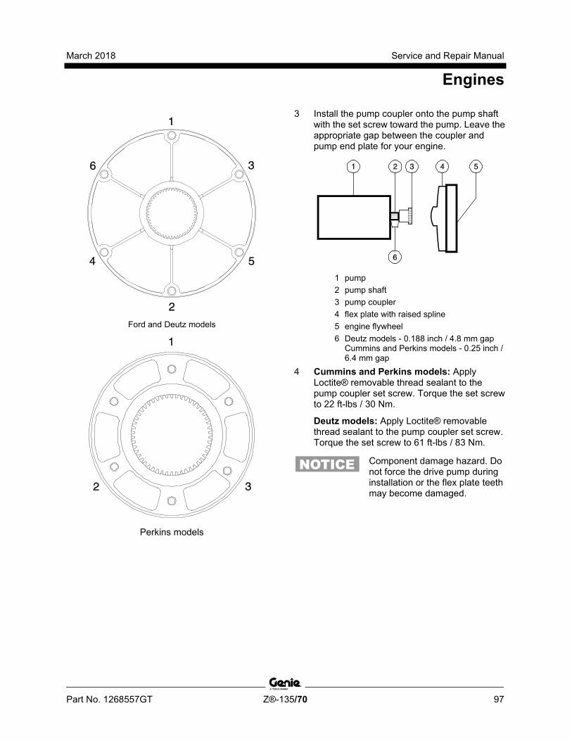
March 2018 Service and Repair Manual
Engines
Part No. 1268557GT Z®-135/70 97
Ford and Deutz models
Perkins models
3 Install the pump coupler onto the pump shaft with the set screw toward the pump. Leave the appropriate gap between the coupler and pump end plate for your engine.
1 pump 2 pump shaft 3 pump coupler 4 flex plate with raised spline 5 engine flywheel 6 Deutz models - 0.188 inch / 4.8 mm gap
Cummins and Perkins models - 0.25 inch / 6.4 mm gap
4 Cummins and Perkins models: Apply Loctite® removable thread sealant to the pump coupler set screw. Torque the set screw to 22 ft-lbs / 30 Nm.
Deutz models: Apply Loctite® removable thread sealant to the pump coupler set screw. Torque the set screw to 61 ft-lbs / 83 Nm.
Component damage hazard. Do not force the drive pump during installation or the flex plate teeth may become damaged.
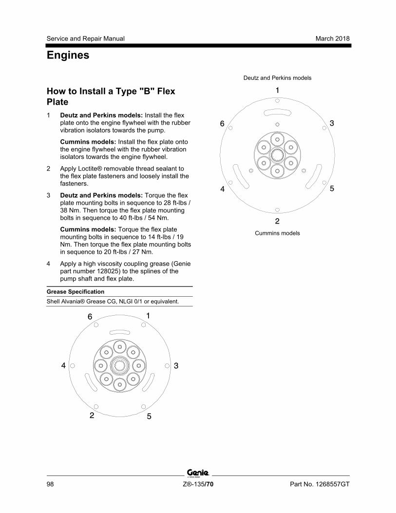
Service and Repair Manual March 2018
Engines
98 Z®-135/70 Part No. 1268557GT
How to i nstall a Type "B" Flex Pl ate
How to Install a Type "B" Flex Plate 1 Deutz and Perkins models: Install the flex
plate onto the engine flywheel with the rubber vibration isolators towards the pump.
Cummins models: Install the flex plate onto the engine flywheel with the rubber vibration isolators towards the engine flywheel.
2 Apply Loctite® removable thread sealant to the flex plate fasteners and loosely install the fasteners.
3 Deutz and Perkins models: Torque the flex plate mounting bolts in sequence to 28 ft-lbs / 38 Nm. Then torque the flex plate mounting bolts in sequence to 40 ft-lbs / 54 Nm.
Cummins models: Torque the flex plate mounting bolts in sequence to 14 ft-lbs / 19 Nm. Then torque the flex plate mounting bolts in sequence to 20 ft-lbs / 27 Nm.
4 Apply a high viscosity coupling grease (Genie part number 128025) to the splines of the pump shaft and flex plate.
Grease Specification Shell Alvania® Grease CG, NLGI 0/1 or equivalent.
Deutz and Perkins models
Cummins models
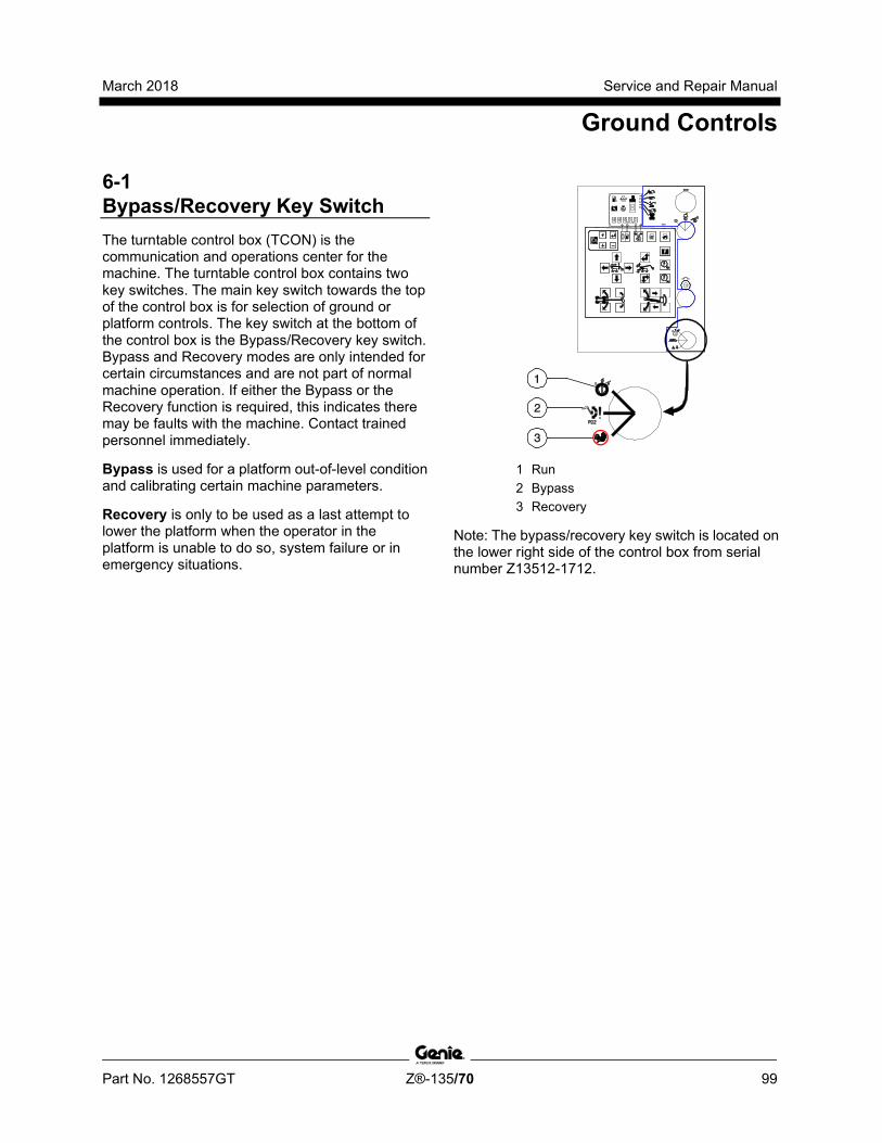
March 2018 Service and Repair Manual
Ground Controls
Part No. 1268557GT Z®-135/70 99
6-1 Bypass/Recovery Key Switch The turntable control box (TCON) is the communication and operations center for the machine. The turntable control box contains two key switches. The main key switch towards the top of the control box is for selection of ground or platform controls. The key switch at the bottom of the control box is the Bypass/Recovery key switch. Bypass and Recovery modes are only intended for certain circumstances and are not part of normal machine operation. If either the Bypass or the Recovery function is required, this indicates there may be faults with the machine. Contact trained personnel immediately.
Bypass is used for a platform out-of-level condition and calibrating certain machine parameters.
Recovery is only to be used as a last attempt to lower the platform when the operator in the platform is unable to do so, system failure or in emergency situations.
1 Run 2 Bypass 3 Recovery
Note: The bypass/recovery key switch is located on the lower right side of the control box from serial number Z13512-1712.
Service and Repair Manual March 2018
Ground Controls
100 Z®-135/70 Part No. 1268557GT
How to Use the Bypass Mode
Tip-over hazard. Operating the machine outside of the operating envelope while in Bypass mode will result in death or serious injury if proper operating procedures and safety precautions are not followed. Do not use this mode if you are not trained and familiar with the operating envelope of the machine.
Note: Before using the Bypass mode, make sure you understand the fault code or issue affecting the operation of the machine to be sure the use of bypass is required.
The Bypass mode will allow the platform to be manually leveled when an out-of-level condition exists. In the event that the platform angle is greater than 10° from level, the boom angle and platform level functions are disabled. Use of the Bypass mode will allow the platform to be manually adjusted to within the normal operating envelope, ±4.5°. Only auxiliary power can be used to correct an out of level platform fault.
1 Turn the engine off.
2 Turn the main key switch to ground controls. Remove the key from the main key switch and insert the key into the bypass/recovery key switch.
Note: The main key switch must remain in the ground control position.
3 Turn the bypass/recovery key switch to the bypass position.
4 Using auxiliary power, operate the ground control buttons to level the platform.
Note: Only the auxiliary power unit can be used to correct an out of level platform fault.
5 Turn the bypass/recovery key switch to the run position.
6 Remove the key from the bypass/recovery key switch and insert the key into the main key switch.
Note: If the Bypass function has been used, there may be faults with the machine. Check the LCD screen on the ground control box for machine faults, then contact trained service personnel.
March 2018 Service and Repair Manual
Ground Controls
Part No. 1268557GT Z®-135/70 101
How to Use the R ecovery Mode
How to Use the Recovery Mode Recovery is only to be used as a last attempt to lower the platform when the operator in the platform is unable to do so, system failure or in emergency situations.
Bodily injury hazard. When using recovery mode, the platform may not fully lower to the ground when the recovery mode is completed. Failure to use only suitable equipment and/or practices to allow the operator to safely exit the platform could result in death or serious injury.
Bodily injury hazard. Platform leveling is not active when using recovery mode. The platform could reach high out-of-level conditions when using this mode. The operator will need to secure themself to the platform to prevent falling injury.
The Recovery mode allows the platform to be lowered in the event the operator in the platform is unable to lower the platform using the platform controls, system failure or emergency situations. The recovery sequence will automatically retract the primary boom, retract the secondary boom and then lower the primary boom using the auxiliary power unit to allow the operator at the platform controls to exit the platform.
Note: This procedure is for machines using software version 1.11 and later. For machines using software version 1.01, contact Genie Product Support.
1 Turn the main key switch to ground controls. Remove the key from the main key switch and insert the key into the bypass/recovery key switch.
Note: If this procedure is performed with the main key switch in the off position an active latched safety fault will be set and will have to be cleared.
2 Turn and hold the bypass/recovery key switch to the recovery position. The switch must be held in the recovery position.
Result: The auxiliary power unit will turn on and the boom will begin the following recovery sequence.
• The primary boom will retract.
• The secondary boom will retract.
• The primary boom will lower.
Note: The key switch must be held in the recovery position until the recovery sequence is complete or until the operator in the platform can safely exit the platform.
Note: If any boom safety limit switches are faulty, the boom will only retract and not lower and the operator will need to be recovered from that point.
Note: If the event the platform becomes out of level ± 15°, all functions using auxiliary power will be disabled, PLATFORM LEVEL > 15 DEGREES will be displayed on the ground control LCD screen, and the operator will have to be recovered using the Recovery Mode.
Note: If the Recovery function has been used, this may indicate there may be faults with the machine. Tag and remove the machine from service until the fault has been corrected by trained personnel.
Service and Repair Manual March 2018
Ground Controls
102 Z®-135/70 Part No. 1268557GT
6-2 Circuit Boards The ground control box contains a replaceable membrane decal with touch sensitive buttons for various machine functions. The ground control box also contains two printed circuit boards:
The LCD (Liquid Crystal Display) circuit board is mounted to the inside of the control box lid which controls the LCD display screen.
The ECM circuit board is the main circuit board for the machine. All operating parameters and configuration of options for the machine are stored in the ECM memory.
Note: When the ECM circuit board is replaced, the machine will need to be fully calibrated. Refer to Repair Procedure, How to Fully Calibrate the Machine.
How to Remove the LCD Display Screen Circuit Board 1 Push in the red Emergency Stop button to the
off position at both the ground and platform controls.
2 Remove the ground control box lid fasteners.
3 Open the ground control box.
Electrocution/burn hazard. Contact with electrically charged circuits could result in death or serious injury. Remove all rings, watches and other jewelry.
Component damage hazard. Electrostatic discharge (ESD) can damage printed circuit board components. Maintain firm contact with a metal part of the machine that is grounded at all times when handling printed circuit boards OR use a grounded wrist strap.
4 Carefully disconnect the LCD circuit board ribbon cable from the ECM circuit board.
5 Remove the LCD display circuit board retaining fasteners.
6 Carefully remove the LCD display circuit board from the ground control box lid.
March 2018 Service and Repair Manual
Ground Controls
Part No. 1268557GT Z®-135/70 103
How to Remove the ALC-1000 Circuit Board Note: If the ALC-1000 circuit board (TCON) has been replaced, the entire machine must be calibrated in a specific order. Refer to Repair Procedure, Full Machine Calibration.
1 Push in the red Emergency Stop button to the off position at both the ground and platform controls.
2 Remove the ground control box lid fasteners.
3 Open the ground control box.
4 Tag and disconnect the harnesses from the ground control box.
5 Remove the control cable receptacle retaining fasteners from the side of the control box.
6 Attach a grounded wrist strap to the ground screw inside the control box.
Electrocution/burn hazard. Contact with electrically charged circuits could result in death or serious injury. Remove all rings, watches and other jewelry.
Component damage hazard. Electrostatic discharge (ESD) can damage printed circuit board components. Maintain firm contact with a metal part of the machine that is grounded at all times when handling printed circuit boards OR use a grounded wrist strap.
7 Tag and carefully disconnect the wire connectors from the circuit board.
8 Carefully disconnect the LCD circuit board ribbon cable from the ECM circuit board.
9 Carefully disconnect the two ribbon cables from the membrane decal at the ECM circuit board.
10 Remove the circuit board mounting fasteners.
11 Carefully remove the circuit board from the control box.
Service and Repair Manual March 2018
Ground Controls
104 Z®-135/70 Part No. 1268557GT
6-3 Membrane Decal The membrane decal is a special decal that consists of a decal with an electronic membrane on the backside. The membrane contains touch sensitive areas that, when pushed, activate the machine functions. The membrane contains touch sensitive areas that activate the machine functions.
How to Replace the Membrane Decal 1 Turn the key switch to the off position and
push in the red Emergency Stop button to the off position at both the ground and platform controls.
2 Remove the ground control box lid fasteners.
3 Open the ground control box.
4 Carefully disconnect the two ribbon cables from the membrane decal at the ECM circuit board.
Electrocution/burn hazard. Contact with electrically charged circuits could result in death or serious injury. Remove all rings, watches and other jewelry.
Component damage hazard. Electrostatic discharge (ESD) can damage printed circuit board components. Maintain firm contact with a metal part of the machine that is grounded at all times when handling printed circuit boards OR use a grounded wrist strap.
5 Carefully remove the membrane decal from the control box lid while guiding the ribbon cables out of the control box lid.
6 Remove any decal adhesive from the control box lid with a mild solvent.
Note: Do not allow any solvent to come in contact with the LCD display screen.
7 Install the new membrane decal while guiding the ribbon cables through the control box lid.
8 Connect the ribbon cables to the ECM circuit board.
9 Close the control box lid and install the retaining fasteners.
March 2018 Service and Repair Manual
Ground Controls
Part No. 1268557GT Z®-135/70 105
6-4 Full Machine Calibration Full machine calibration must be completed in the proper sequence when the ALC-1000 circuit board (TCON) in the ground control box has been replaced or the turntable level sensor (SCON) has been replaced.
How to Fully Calibrate the Machine Calibration procedures shall only be completed by qualified technicians that have Genie factory service training.
Tip-over hazard. Failure to calibrate the machine in the proper sequence could cause the machine to tip over resulting in death or serious injury.
Note: A digital level will be required to perform this procedure.
Note: A kit is available through Genie Product Support (Genie part number 58351). This kit includes a digital level with a magnetic base and cable harnesses.
Note: Use the following chart to identify the description of each LCD screen control button used in this procedure.
Plus Minus Previous Enter
Note: Start this procedure with the booms in the fully stowed position and the axle retracted.
Full machine calibration must be completed in the following sequence:
• Select engine configuration. Refer to Repair Section, Display Module. Unit of Measure and Language.
• Joysticks. Refer to Repair Procedure, How to Calibrate a Joystick.
• Turntable level sensor. Refer to Repair Procedure, How to Calibrate the Turntable Level Sensor.
• Platform level sensor. Refer to Repair Procedure, How to Calibrate the Platform Level Sensor.
• Axle angle sensors. Refer to Repair Procedure, How to Calibrate the Axle Angle Sensors.
• Steer sensors. Refer to Repair Procedure, How to Calibrate All Steer Sensors.
• Secondary boom angle sensor. Refer to Repair Procedure, How to Calibrate the Secondary Boom Angle Sensor.
• Primary boom angle sensor. Refer to Repair Procedure, How to Calibrate the Primary Boom Angle Sensor.
• Jib boom bellcrank angle sensor. Refer to Repair Procedure, How to Calibrate the Jib Boom Bellcrank Sensor.
• Select option configuration. Refer to Repair Section, Display Module. Options.

Service and Repair Manual March 2018
Display Module
106 Z®-135/70 Part No. 1268557GT
This table lists the various screens and menu options of the operating software. Some display menus are for informational purpose only, while others can be used to change the machine operating parameters.
Tip-over hazard. Calibration and parameter settings must be completed by a person trained and qualified on the repair of this machine. Failure to properly calibrate or set parameters could cause the machine to tip over resulting in death or serious injury.
Note: The key switch must be in the off position before entering the programming mode.
Note: Use the following chart to identify the description of each LCD screen control button used in this procedure.
Plus Minus Previous Enter
Activation of the enter or previous buttons scrolls through the screens. To change parameter values or select a setting, use the plus button (to increase or scroll forward) and the minus button (to decrease or scroll backwards). Then press the enter button to save the new value to memory. An audible beep will indicate a save to memory. Use the enter and previous buttons to scroll to the EXIT menu. Use the plus button to change to YES and use the enter button to exit.
Screen or Menu Procedure Description Range or Selection Operator Default Hourmeter (on power up)
Engine speed
Engine oil pressure PSI (English)
Engine oil pressure kPa (metric)
Engine temperature °F (Engiish) engine temp will not display until temp is >100°F
Engine temperature °C (metric) engine temp will not display until temp is >38°C
Primary boom angle to gravity
Turntable level sensor X° direction
Turntable level sensor Y° direction
Platform level sensor degree
Battery volts
March 2018 Service and Repair Manual
Display Module
Part No. 1268557GT Z®-135/70 107
Screen or Menu
Procedure Description Range or Selection
Machine Status With key switch on, press the (plus)(minus) buttons at the same time.
Hydraulic pressure PSI (English)
0-4500 PSI
Hydraulic pressure kPa (metric) 0-31000 kPa
Primary boom to secondary boom angle
+22° to +136°
Primary boom length =0', >0', >22
Secondary boom angle* -3.5° to 76°
Secondary boom length =0FT, >0 FT
Jib bellcrank angle -10° to +10° *(referenced to chassis tilt angle)
DPF Regeneration Mode (Auto / Force / Inhibit)
Unit of Measure and Language
With key switch OFF, press and hold the enter button and turn key switch to on position. Release the enter button and press (plus)(minus)(minus)(plus).
Metric/English (measurement units)
English, German, French, Spanish, Portuguese, Italian, Dutch, and Swedish.
Set engine Deutz TD2011L04i (DL04i)
Perkins 1104D-44T (P1104)
Overload Recovery (software V3.07 and later)
Clear Overload Recovery YES/NO A passcode is required to clear the message
Default Reset With key switch OFF, press and hold the enter button and turn key switch to on position. Release the enter button and press (minus)(minus)(previous)(previous)
Delete drive functions
Software version 3.11 or lower and software version 4.01
Delete boom function speed
Delete lift function ramps
Delete all (Contact Genie Product Support before using this option)
Delete Faults Delete faults will reset active latching faults. Delete faults will not clear fault history.
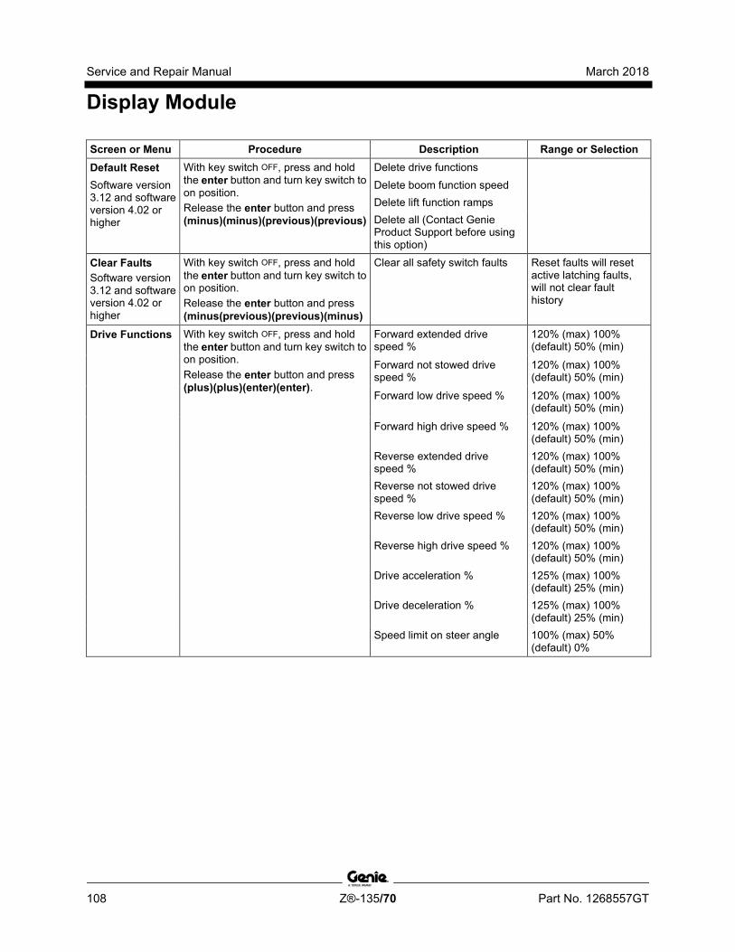
Service and Repair Manual March 2018
Display Module
108 Z®-135/70 Part No. 1268557GT
Screen or Menu Procedure Description Range or Selection Default Reset With key switch OFF, press and hold
the enter button and turn key switch to on position. Release the enter button and press (minus)(minus)(previous)(previous)
Delete drive functions Software version 3.12 and software version 4.02 or higher
Delete boom function speed Delete lift function ramps Delete all (Contact Genie Product Support before using this option)
Clear Faults Software version 3.12 and software version 4.02 or higher
With key switch OFF, press and hold the enter button and turn key switch to on position. Release the enter button and press (minus(previous)(previous)(minus)
Clear all safety switch faults Reset faults will reset active latching faults, will not clear fault history
Drive Functions With key switch OFF, press and hold the enter button and turn key switch to on position. Release the enter button and press (plus)(plus)(enter)(enter).
Forward extended drive speed %
120% (max) 100% (default) 50% (min)
Forward not stowed drive speed %
120% (max) 100% (default) 50% (min)
Forward low drive speed % 120% (max) 100% (default) 50% (min)
Forward high drive speed % 120% (max) 100% (default) 50% (min)
Reverse extended drive speed %
120% (max) 100% (default) 50% (min)
Reverse not stowed drive speed %
120% (max) 100% (default) 50% (min)
Reverse low drive speed % 120% (max) 100% (default) 50% (min)
Reverse high drive speed % 120% (max) 100% (default) 50% (min)
Drive acceleration % 125% (max) 100% (default) 25% (min)
Drive deceleration % 125% (max) 100% (default) 25% (min)
Speed limit on steer angle 100% (max) 50% (default) 0%

March 2018 Service and Repair Manual
Display Module
Part No. 1268557GT Z®-135/70 109
Screen or Menu
Procedure Description Range or Selection
Boom Function Speeds
With key switch OFF, press and hold the enter button and turn key switch to on position. Release the enter button and press (plus)(plus)(minus)(minus)
Primary boom up speed stowed
Primary boom up speed not stowed
Primary boom down speed stowed
Primary boom down speed not stowed
Primary boom extend speed
Primary boom retract speed
Secondary boom up speed stowed
Secondary boom up speed not stowed
Secondary boom down speed stowed 120% max, 50% min,
Secondary boom down speed not stowed 100% (default)
Secondary boom extend speed
Secondary boom retract speed
Turntable rotate speed retracted
Turntable rotate speed not retracted
Turntable rotate speed extended
Jib up speed retracted
Jib up speed not retracted
Jib down speed retracted
Jib down speed not retracted

Service and Repair Manual March 2018
Display Module
110 Z®-135/70 Part No. 1268557GT
Screen or Menu Procedure Description Range or Selection
Lift Functions Ramps
With key switch OFF, press and hold the enter button and turn key switch to on position. Release the enter button and press (plus)(plus)(previous)(previous).
Primary boom up/down ramp acceleration %
Primary boom up/down ramp deceleration %
Primary boom extend/retract ramp acceleration %
Primary boom extend/retract ramp deceleration %
150% max and 50% min 100% (default),
Secondary boom up/down ramp acceleration %
5% increment
Secondary boom up/down ramp deceleration %
Secondary boom extend/retract ramp acceleration %
Secondary boom extend/retract ramp deceleration %
Turntable rotate ramp acceleration %
Turntable rotate ramp deceleration %
Jib boom up/down ramp acceleration % 120% max and 50% min, 100% (default), 5% incr
Jib boom up/down ramp deceleration %
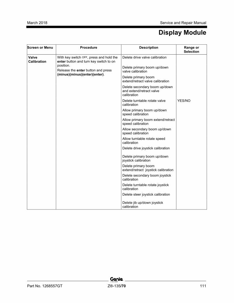
March 2018 Service and Repair Manual
Display Module
Part No. 1268557GT Z®-135/70 111
Screen or Menu Procedure Description Range or Selection
Valve Calibration
With key switch OFF, press and hold the enter button and turn key switch to on position. Release the enter button and press (minus)(minus)(enter)(enter).
Delete drive valve calibration
Delete primary boom up/down valve calibration
Delete primary boom extend/retract valve calibration
Delete secondary boom up/down and extend/retract valve calibration
Delete turntable rotate valve calibration
YES/NO
Allow primary boom up/down speed calibration
Allow primary boom extend/retract speed calibration
Allow secondary boom up/down speed calibration
Allow turntable rotate speed calibration
Delete drive joystick calibration
Delete primary boom up/down joystick calibration
Delete primary boom extend/retract joystick calibration
Delete secondary boom joystick calibration
Delete turntable rotate joystick calibration
Delete steer joystick calibration
Delete jib up/down joystick calibration
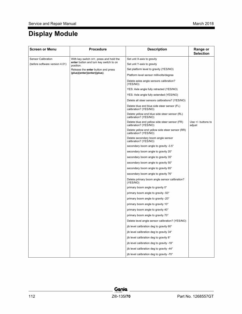
Service and Repair Manual March 2018
Display Module
112 Z®-135/70 Part No. 1268557GT
Screen or Menu Procedure Description Range or Selection
Sensor Calibration With key switch OFF, press and hold the enter button and turn key switch to on position. Release the enter button and press (plus)(enter)(enter)(plus).
Set unit X-axis to gravity
(before software version 4.01) Set unit Y-axis to gravity
Set platform level to gravity (YES/NO)
Platform level sensor millivolts/degree
Delete axles angle sensors calibration? (YES/NO)
YES: Axle angle fully retracted (YES/NO)
YES: Axle angle fully extended (YES/NO)
Delete all steer sensors calibrations? (YES/NO)
Delete blue end blue side steer sensor (FL) calibration? (YES/NO)
Delete yellow end blue side steer sensor (RL) calibration? (YES/NO)
Delete blue end yellow side steer sensor (FR) calibration? (YES/NO)
Use +/- buttons to adjust
Delete yellow end yellow side steer sensor (RR) calibration? (YES/NO)
Delete secondary boom angle sensor calibration? (YES/NO)
secondary boom angle to gravity -3.5°
secondary boom angle to gravity 20°
secondary boom angle to gravity 35°
secondary boom angle to gravity 50°
secondary boom angle to gravity 65°
secondary boom angle to gravity 76°
Delete primary boom angle sensor calibration? (YES/NO)
primary boom angle to gravity 0°
primary boom angle to gravity -50°
primary boom angle to gravity -20°
primary boom angle to gravity 10°
primary boom angle to gravity 40°
primary boom angle to gravity 70°
Delete level angle sensor calibration? (YES/NO)
jib level calibration deg to gravity 60°
jib level calibration deg to gravity 34°
jib level calibration deg to gravity 8°
jib level calibration deg to gravity -18°
jib level calibration deg to gravity -44°
jib level calibration deg to gravity -70°
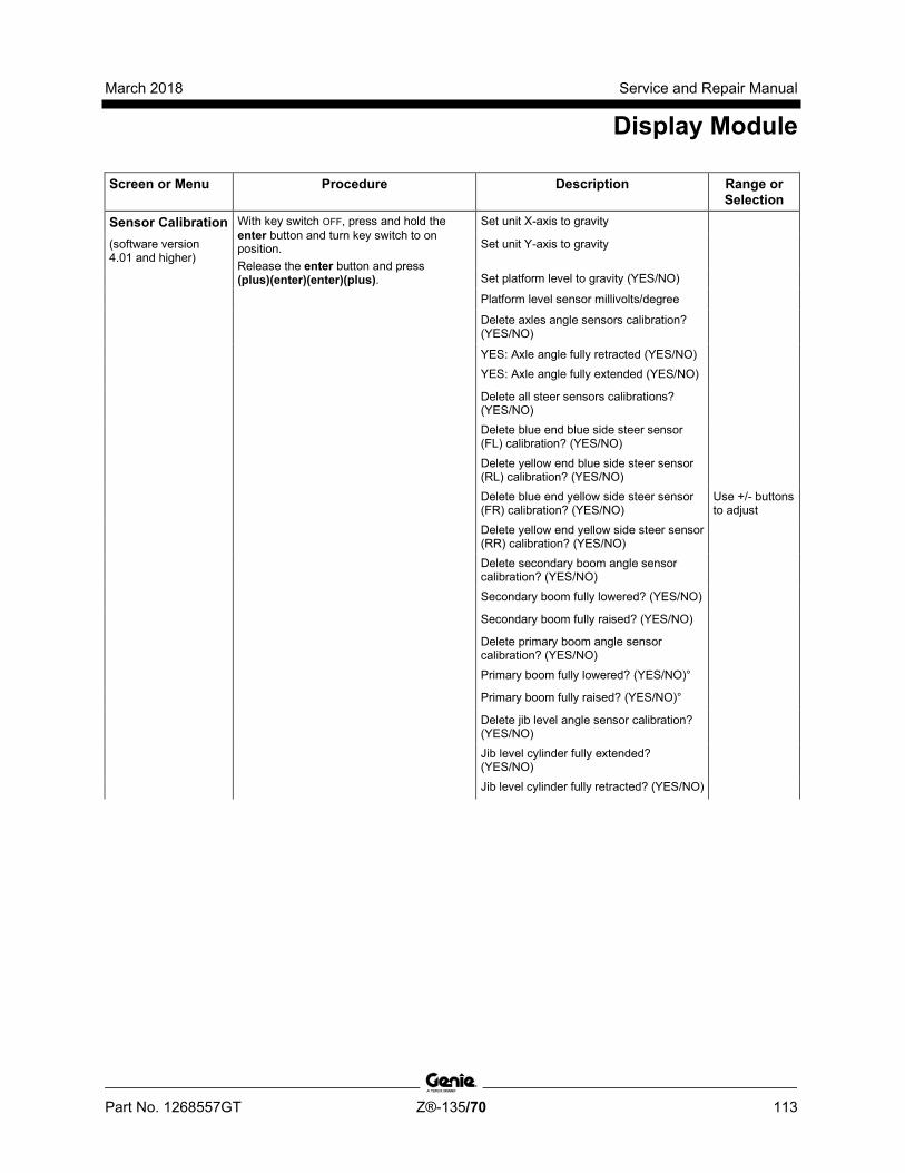
March 2018 Service and Repair Manual
Display Module
Part No. 1268557GT Z®-135/70 113
Screen or Menu Procedure Description Range or Selection
Sensor Calibration With key switch OFF, press and hold the enter button and turn key switch to on position. Release the enter button and press (plus)(enter)(enter)(plus).
Set unit X-axis to gravity
(software version 4.01 and higher)
Set unit Y-axis to gravity
Set platform level to gravity (YES/NO) Platform level sensor millivolts/degree Delete axles angle sensors calibration?
(YES/NO)
YES: Axle angle fully retracted (YES/NO) YES: Axle angle fully extended (YES/NO)
Delete all steer sensors calibrations? (YES/NO)
Delete blue end blue side steer sensor (FL) calibration? (YES/NO)
Delete yellow end blue side steer sensor (RL) calibration? (YES/NO)
Delete blue end yellow side steer sensor (FR) calibration? (YES/NO)
Use +/- buttons to adjust
Delete yellow end yellow side steer sensor (RR) calibration? (YES/NO)
Delete secondary boom angle sensor calibration? (YES/NO)
Secondary boom fully lowered? (YES/NO)
Secondary boom fully raised? (YES/NO) Delete primary boom angle sensor
calibration? (YES/NO)
Primary boom fully lowered? (YES/NO)° Primary boom fully raised? (YES/NO)°
Delete jib level angle sensor calibration? (YES/NO)
Jib level cylinder fully extended? (YES/NO)
Jib level cylinder fully retracted? (YES/NO)
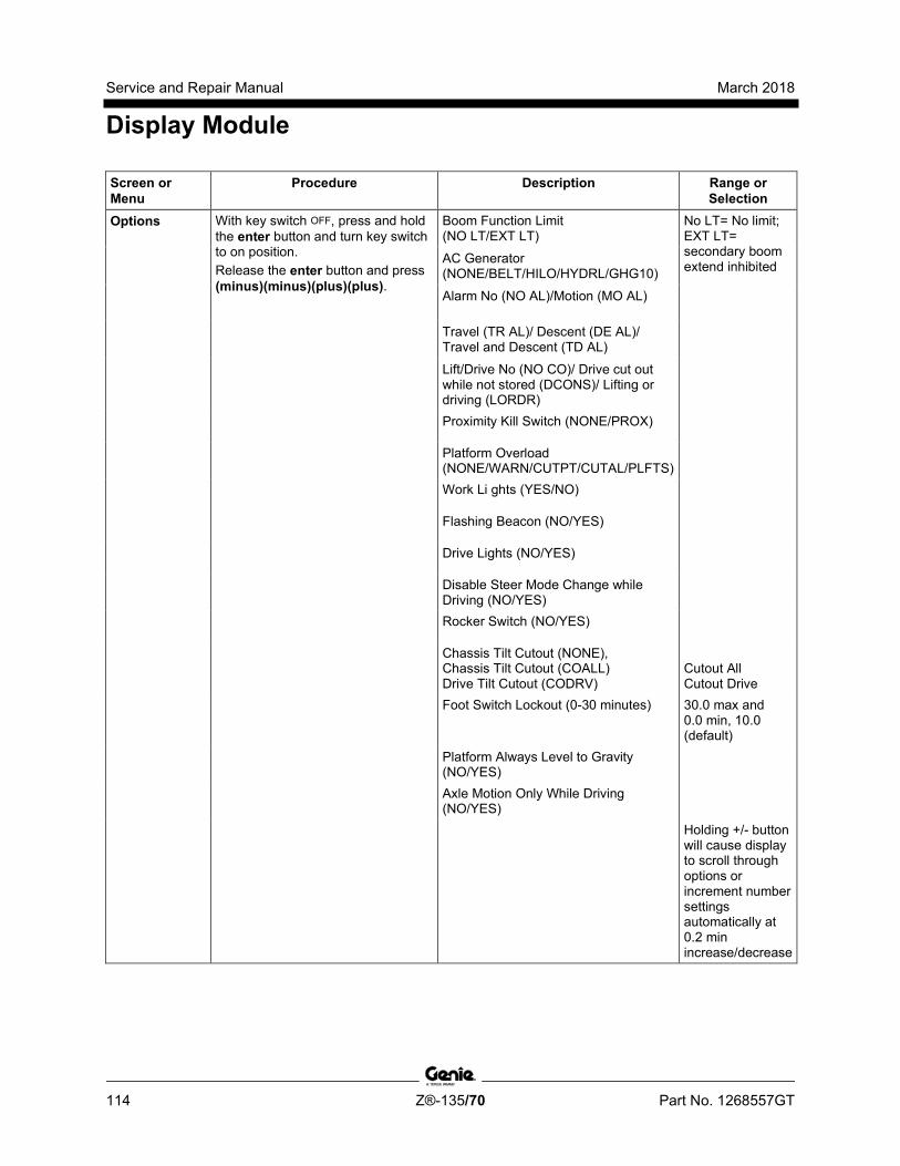
Service and Repair Manual March 2018
Display Module
114 Z®-135/70 Part No. 1268557GT
Screen or Menu
Procedure Description Range or Selection
Options With key switch OFF, press and hold the enter button and turn key switch to on position. Release the enter button and press (minus)(minus)(plus)(plus).
Boom Function Limit (NO LT/EXT LT)
No LT= No limit; EXT LT= secondary boom extend inhibited AC Generator
(NONE/BELT/HILO/HYDRL/GHG10)
Alarm No (NO AL)/Motion (MO AL)
Travel (TR AL)/ Descent (DE AL)/ Travel and Descent (TD AL)
Lift/Drive No (NO CO)/ Drive cut out while not stored (DCONS)/ Lifting or driving (LORDR)
Proximity Kill Switch (NONE/PROX)
Platform Overload (NONE/WARN/CUTPT/CUTAL/PLFTS)
Work Li ghts (YES/NO)
Flashing Beacon (NO/YES)
Drive Lights (NO/YES)
Disable Steer Mode Change while Driving (NO/YES)
Rocker Switch (NO/YES)
Chassis Tilt Cutout (NONE), Chassis Tilt Cutout (COALL) Drive Tilt Cutout (CODRV)
Cutout All Cutout Drive
Foot Switch Lockout (0-30 minutes) 30.0 max and 0.0 min, 10.0 (default)
Platform Always Level to Gravity (NO/YES)
Axle Motion Only While Driving (NO/YES)
Holding +/- button will cause display to scroll through options or increment number settings automatically at 0.2 min increase/decrease
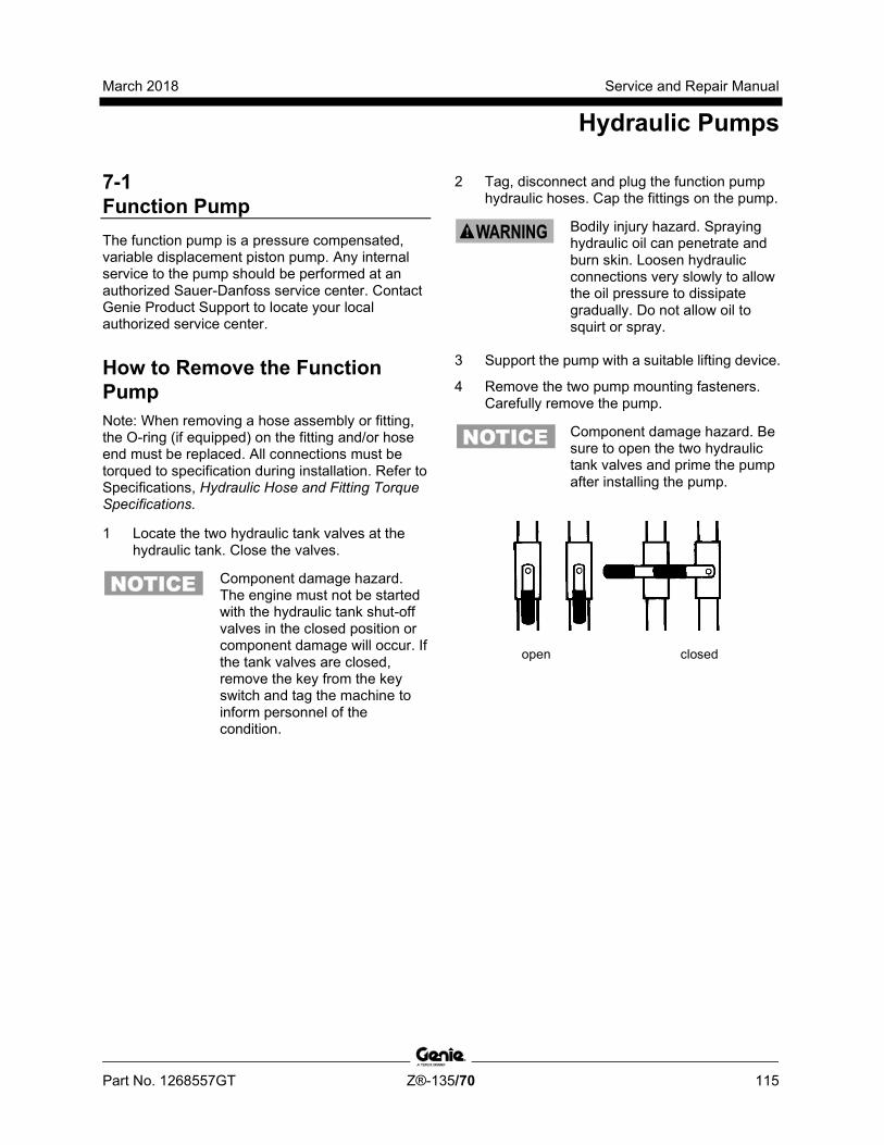
March 2018 Service and Repair Manual
Hydraulic Pumps
Part No. 1268557GT Z®-135/70 115
7-1 Function Pump The function pump is a pressure compensated, variable displacement piston pump. Any internal service to the pump should be performed at an authorized Sauer-Danfoss service center. Contact Genie Product Support to locate your local authorized service center.
How to Remove the Function Pump Note: When removing a hose assembly or fitting, the O-ring (if equipped) on the fitting and/or hose end must be replaced. All connections must be torqued to specification during installation. Refer to Specifications, Hydraulic Hose and Fitting Torque Specifications.
1 Locate the two hydraulic tank valves at the hydraulic tank. Close the valves.
Component damage hazard. The engine must not be started with the hydraulic tank shut-off valves in the closed position or component damage will occur. If the tank valves are closed, remove the key from the key switch and tag the machine to inform personnel of the condition.
2 Tag, disconnect and plug the function pump hydraulic hoses. Cap the fittings on the pump.
Bodily injury hazard. Spraying hydraulic oil can penetrate and burn skin. Loosen hydraulic connections very slowly to allow the oil pressure to dissipate gradually. Do not allow oil to squirt or spray.
3 Support the pump with a suitable lifting device.
4 Remove the two pump mounting fasteners. Carefully remove the pump.
Component damage hazard. Be sure to open the two hydraulic tank valves and prime the pump after installing the pump.
open closed

Service and Repair Manual March 2018
Hydraulic Pumps
116 Z®-135/70 Part No. 1268557GT
How to Prime the Functi on Pump
How to Prime the Function Pump Note: When removing a hose assembly or fitting, the O-ring (if equipped) on the fitting and/or hose end must be replaced. All connections must be torqued to specification during installation. Refer to Specifications, Hydraulic Hose and Fitting Torque Specifications.
1 Remove the case drain hydraulic hose from the top of the function pump.
Note: The case drain hose is the smaller of the two hoses on top of the function pump and closest to the drive pump.
2 Locate and open the hydraulic tank shut-off valve at the hydraulic tank that supplies hydraulic oil to the function pump. Do not open the valve for the drive pump.
3 When hydraulic fluid begins to come out of the case drain port of the function pump, install the function pump case drain hose.
4 Clean up any oil that may have spilled. Properly discard the used oil.
5 Start the engine from the ground controls.
6 Check for hydraulic leaks.
How to Adj ust the Functi on Pum p Standby Pr essure
How to Adjust the Function Pump Standby Pressure 1 Connect a 0 to 5000 psi / 0 to 350 bar
pressure gauge to the test port on the function manifold
2 Start the engine from the ground controls and allow the engine to run at low idle.
3 Observe the pressure reading on the pressure gauge.
Result: The gauge should show 250 psi / 17 bar.
Result: If the gauge does not show 250 psi / 17 bar, proceed with step 4 to adjust the function pump standby pressure.
4 Loosen the set screw for the standby pressure adjustment screw.
1 standby pressure set screw 2 standby pressure adjustment screw
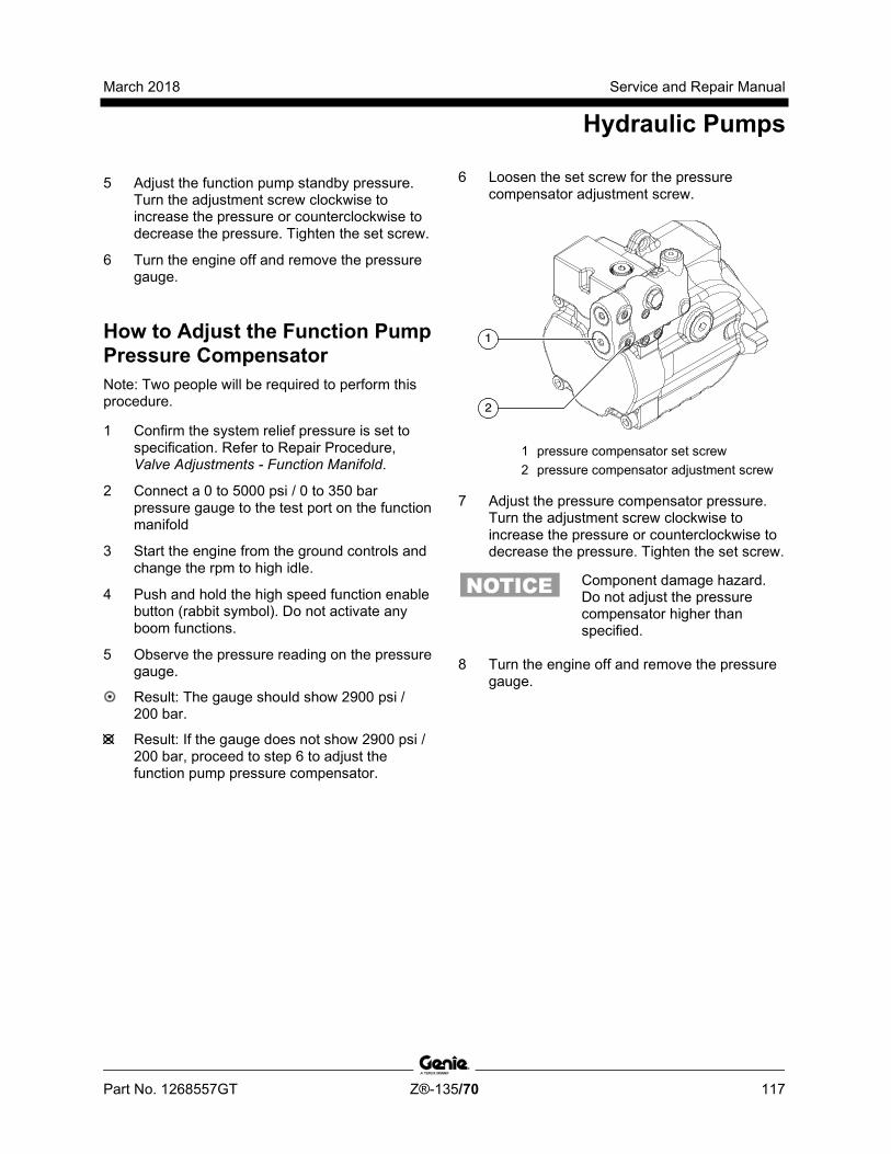
March 2018 Service and Repair Manual
Hydraulic Pumps
Part No. 1268557GT Z®-135/70 117
5 Adjust the function pump standby pressure. Turn the adjustment screw clockwise to increase the pressure or counterclockwise to decrease the pressure. Tighten the set screw.
6 Turn the engine off and remove the pressure gauge.
How to Adj ust the Functi on Pum p Pressure Com pensator
How to Adjust the Function Pump Pressure Compensator Note: Two people will be required to perform this procedure.
1 Confirm the system relief pressure is set to specification. Refer to Repair Procedure, Valve Adjustments - Function Manifold.
2 Connect a 0 to 5000 psi / 0 to 350 bar pressure gauge to the test port on the function manifold
3 Start the engine from the ground controls and change the rpm to high idle.
4 Push and hold the high speed function enable button (rabbit symbol). Do not activate any boom functions.
5 Observe the pressure reading on the pressure gauge.
Result: The gauge should show 2900 psi / 200 bar.
Result: If the gauge does not show 2900 psi / 200 bar, proceed to step 6 to adjust the function pump pressure compensator.
6 Loosen the set screw for the pressure compensator adjustment screw.
1 pressure compensator set screw 2 pressure compensator adjustment screw
7 Adjust the pressure compensator pressure. Turn the adjustment screw clockwise to increase the pressure or counterclockwise to decrease the pressure. Tighten the set screw.
Component damage hazard. Do not adjust the pressure compensator higher than specified.
8 Turn the engine off and remove the pressure gauge.
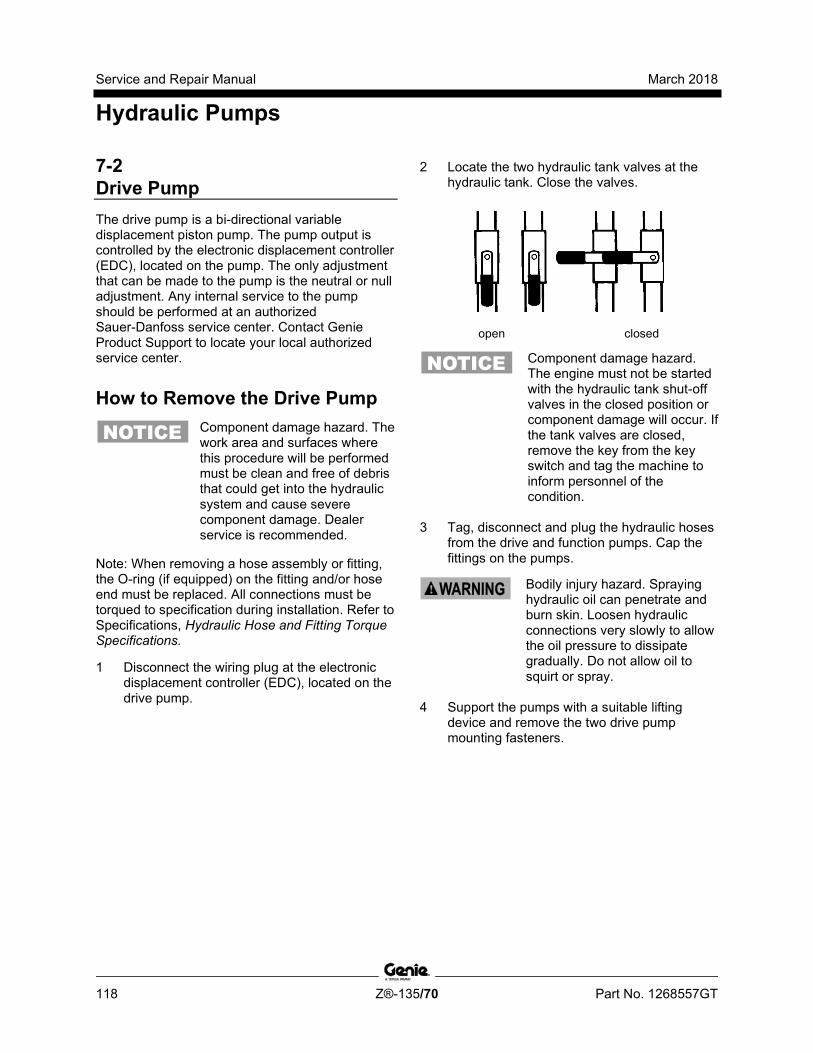
Service and Repair Manual March 2018
Hydraulic Pumps
118 Z®-135/70 Part No. 1268557GT
7-2 Drive Pump The drive pump is a bi-directional variable displacement piston pump. The pump output is controlled by the electronic displacement controller (EDC), located on the pump. The only adjustment that can be made to the pump is the neutral or null adjustment. Any internal service to the pump should be performed at an authorized Sauer-Danfoss service center. Contact Genie Product Support to locate your local authorized service center.
How to Remove the Drive Pump
Component damage hazard. The work area and surfaces where this procedure will be performed must be clean and free of debris that could get into the hydraulic system and cause severe component damage. Dealer service is recommended.
Note: When removing a hose assembly or fitting, the O-ring (if equipped) on the fitting and/or hose end must be replaced. All connections must be torqued to specification during installation. Refer to Specifications, Hydraulic Hose and Fitting Torque Specifications.
1 Disconnect the wiring plug at the electronic displacement controller (EDC), located on the drive pump.
2 Locate the two hydraulic tank valves at the hydraulic tank. Close the valves.
open closed
Component damage hazard. The engine must not be started with the hydraulic tank shut-off valves in the closed position or component damage will occur. If the tank valves are closed, remove the key from the key switch and tag the machine to inform personnel of the condition.
3 Tag, disconnect and plug the hydraulic hoses from the drive and function pumps. Cap the fittings on the pumps.
Bodily injury hazard. Spraying hydraulic oil can penetrate and burn skin. Loosen hydraulic connections very slowly to allow the oil pressure to dissipate gradually. Do not allow oil to squirt or spray.
4 Support the pumps with a suitable lifting device and remove the two drive pump mounting fasteners.
March 2018 Service and Repair Manual
Hydraulic Pumps
Part No. 1268557GT Z®-135/70 119
5 Carefully pull the drive pump out until the pump coupler separates from the flex plate.
6 Remove the drive pump from the machine.
Component damage hazard. The pump(s) may become unbalanced and fall if not properly supported.
Component damage hazard. The engine must not be started with the hydraulic tank shut-off valves in the closed position or component damage will occur. If the tank valves are closed, remove the key from the key switch and tag the machine to inform personnel of the condition.
How to Prime the Drive Pum p
How to Prime the Drive Pump
Component damage hazard. Be sure to open the two hydraulic tank valves before performing this procedure.
1 Connect a 0 to 600 psi / 0 to 50 bar pressure gauge to either the "A" or "B" test port on the drive pump.
2 Perkins models: Disconnect the engine wiring harness from the fuel shutoff solenoid at the injector pump.
Deutz models: Hold the manual fuel shutoff valve clockwise to the closed position.
3 Have another person crank the engine with the starter motor for 15 seconds, wait 15 seconds, then crank the engine an additional 15 seconds or until the pressure reaches approximately 250 psi / 17 bar.
4 Perkins models: Connect the engine wiring harness to the fuel solenoid.
Deutz models: Release the manual fuel shutoff valve.
5 Start the engine from the ground controls.
6 Check for hydraulic leaks.

Service and Repair Manual March 2018
Manifolds
120 Z®-135/70 Part No. 1268557GT
8-1 Function Manifold - View 1 (before serial number 440) The function manifold is mounted to the turntable next to the ground controls.
Index No. Description Schematic
Item Function Torque
1 Check valve W Prevents the draining of hydraulic oil from the jib manifold and platform manifold
30-35 ft-lbs / 41-47 Nm
2 Solenoid Valve, 2 position 3 way C Primary boom up 30-35 ft-lbs / 41-47 Nm
3 Solenoid Valve, 2 position 3 way G Primary boom retract 30-35 ft-lbs / 41-47 Nm 4 Solenoid Valve, 2 position 3 way J Secondary boom extend 50-55 ft-lbs / 68-75 Nm 5 Solenoid Valve, 2 position 3 way H Secondary boom up 50-55 ft-lbs / 68-75 Nm 6 Plug, 16 SAE Port plug 130-140 ft-lbs / 176-190 Nm 7 Relief valve, 3100 psi / 214 bar L System relief 30-35 ft-lbs / 41-47 Nm
8 Solenoid Valve, 2 position 3 way I Secondary boom down 30-35 ft-lbs / 41-47 Nm 9 Solenoid Valve, 2 position 3 way K Secondary boom retract 30-35 ft-lbs / 41-47 Nm 10 Solenoid Valve, 2 position 3 way F Primary boom extend 30-35 ft-lbs / 41-47 Nm 11 Solenoid valve, 3 position 4 way B Turntable rotate left/right 30-35 ft-lbs / 41-47 Nm
12 Solenoid Valve, 2 position 3 way D Primary boom down 30-35 ft-lbs / 41-47 Nm

March 2018 Service and Repair Manual
Manifolds
Part No. 1268557GT Z®-135/70 121
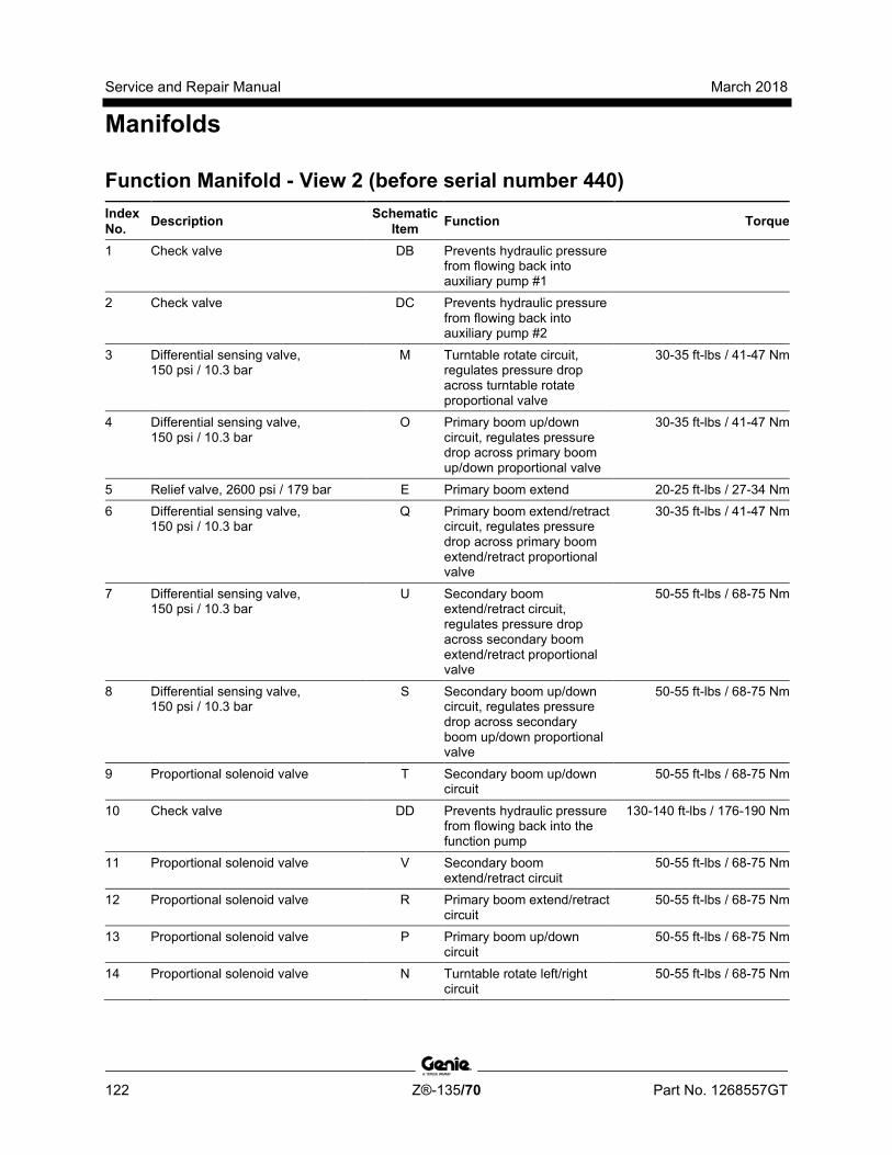
Service and Repair Manual March 2018
Manifolds
122 Z®-135/70 Part No. 1268557GT
Function Manifold - View 2 (before serial number 440) Index No. Description Schematic
Item Function Torque
1 Check valve DB Prevents hydraulic pressure from flowing back into auxiliary pump #1
2 Check valve DC Prevents hydraulic pressure from flowing back into auxiliary pump #2
3 Differential sensing valve, 150 psi / 10.3 bar
M Turntable rotate circuit, regulates pressure drop across turntable rotate proportional valve
30-35 ft-lbs / 41-47 Nm
4 Differential sensing valve, 150 psi / 10.3 bar
O Primary boom up/down circuit, regulates pressure drop across primary boom up/down proportional valve
30-35 ft-lbs / 41-47 Nm
5 Relief valve, 2600 psi / 179 bar E Primary boom extend 20-25 ft-lbs / 27-34 Nm 6 Differential sensing valve,
150 psi / 10.3 bar Q Primary boom extend/retract
circuit, regulates pressure drop across primary boom extend/retract proportional valve
30-35 ft-lbs / 41-47 Nm
7 Differential sensing valve, 150 psi / 10.3 bar
U Secondary boom extend/retract circuit, regulates pressure drop across secondary boom extend/retract proportional valve
50-55 ft-lbs / 68-75 Nm
8 Differential sensing valve, 150 psi / 10.3 bar
S Secondary boom up/down circuit, regulates pressure drop across secondary boom up/down proportional valve
50-55 ft-lbs / 68-75 Nm
9 Proportional solenoid valve T Secondary boom up/down circuit
50-55 ft-lbs / 68-75 Nm
10 Check valve DD Prevents hydraulic pressure from flowing back into the function pump
130-140 ft-lbs / 176-190 Nm
11 Proportional solenoid valve V Secondary boom extend/retract circuit
50-55 ft-lbs / 68-75 Nm
12 Proportional solenoid valve R Primary boom extend/retract circuit
50-55 ft-lbs / 68-75 Nm
13 Proportional solenoid valve P Primary boom up/down circuit
50-55 ft-lbs / 68-75 Nm
14 Proportional solenoid valve N Turntable rotate left/right circuit
50-55 ft-lbs / 68-75 Nm
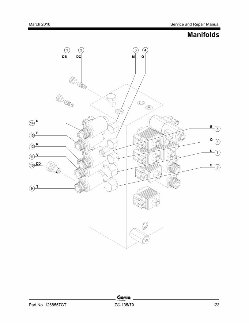
March 2018 Service and Repair Manual
Manifolds
Part No. 1268557GT Z®-135/70 123
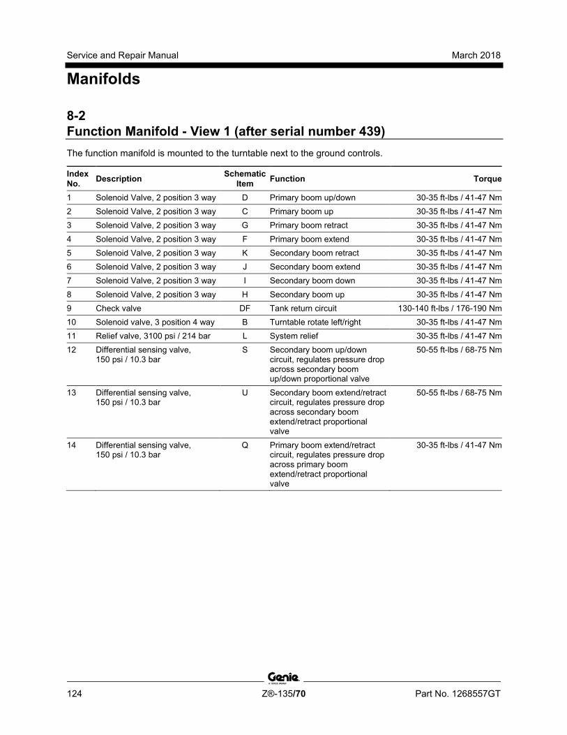
Service and Repair Manual March 2018
Manifolds
124 Z®-135/70 Part No. 1268557GT
8-2 Function Manifold - View 1 (after serial number 439) The function manifold is mounted to the turntable next to the ground controls.
Index No. Description Schematic
Item Function Torque
1 Solenoid Valve, 2 position 3 way D Primary boom up/down 30-35 ft-lbs / 41-47 Nm 2 Solenoid Valve, 2 position 3 way C Primary boom up 30-35 ft-lbs / 41-47 Nm 3 Solenoid Valve, 2 position 3 way G Primary boom retract 30-35 ft-lbs / 41-47 Nm
4 Solenoid Valve, 2 position 3 way F Primary boom extend 30-35 ft-lbs / 41-47 Nm 5 Solenoid Valve, 2 position 3 way K Secondary boom retract 30-35 ft-lbs / 41-47 Nm 6 Solenoid Valve, 2 position 3 way J Secondary boom extend 30-35 ft-lbs / 41-47 Nm 7 Solenoid Valve, 2 position 3 way I Secondary boom down 30-35 ft-lbs / 41-47 Nm
8 Solenoid Valve, 2 position 3 way H Secondary boom up 30-35 ft-lbs / 41-47 Nm 9 Check valve DF Tank return circuit 130-140 ft-lbs / 176-190 Nm 10 Solenoid valve, 3 position 4 way B Turntable rotate left/right 30-35 ft-lbs / 41-47 Nm 11 Relief valve, 3100 psi / 214 bar L System relief 30-35 ft-lbs / 41-47 Nm 12 Differential sensing valve,
150 psi / 10.3 bar S Secondary boom up/down
circuit, regulates pressure drop across secondary boom up/down proportional valve
50-55 ft-lbs / 68-75 Nm
13 Differential sensing valve, 150 psi / 10.3 bar
U Secondary boom extend/retract circuit, regulates pressure drop across secondary boom extend/retract proportional valve
50-55 ft-lbs / 68-75 Nm
14 Differential sensing valve, 150 psi / 10.3 bar
Q Primary boom extend/retract circuit, regulates pressure drop across primary boom extend/retract proportional valve
30-35 ft-lbs / 41-47 Nm
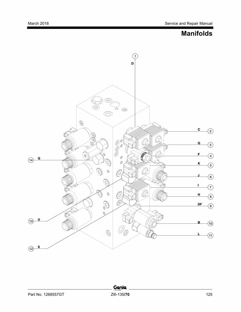
March 2018 Service and Repair Manual
Manifolds
Part No. 1268557GT Z®-135/70 125
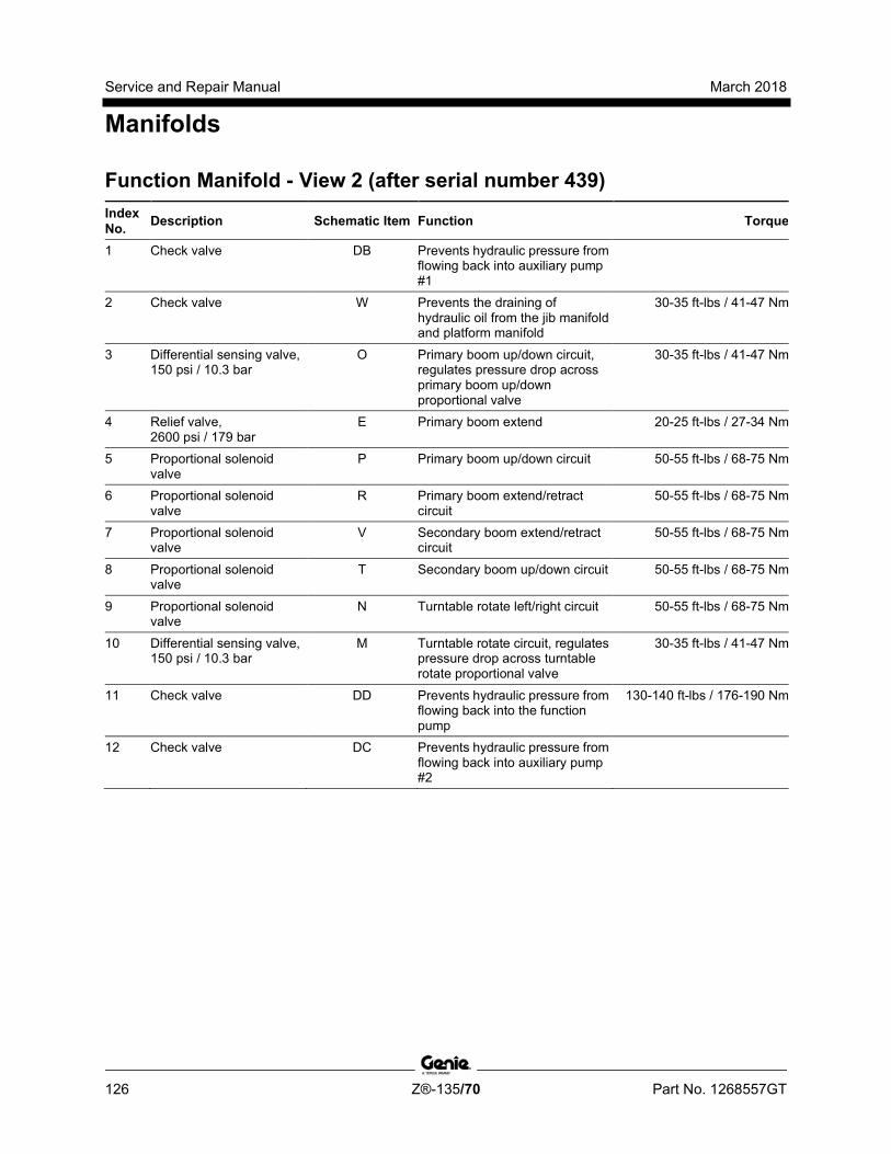
Service and Repair Manual March 2018
Manifolds
126 Z®-135/70 Part No. 1268557GT
Function Manifold - View 2 (after serial number 439) Index No. Description Schematic Item Function Torque
1 Check valve DB Prevents hydraulic pressure from flowing back into auxiliary pump #1
2 Check valve W Prevents the draining of hydraulic oil from the jib manifold and platform manifold
30-35 ft-lbs / 41-47 Nm
3 Differential sensing valve, 150 psi / 10.3 bar
O Primary boom up/down circuit, regulates pressure drop across primary boom up/down proportional valve
30-35 ft-lbs / 41-47 Nm
4 Relief valve, 2600 psi / 179 bar
E Primary boom extend 20-25 ft-lbs / 27-34 Nm
5 Proportional solenoid valve
P Primary boom up/down circuit 50-55 ft-lbs / 68-75 Nm
6 Proportional solenoid valve
R Primary boom extend/retract circuit
50-55 ft-lbs / 68-75 Nm
7 Proportional solenoid valve
V Secondary boom extend/retract circuit
50-55 ft-lbs / 68-75 Nm
8 Proportional solenoid valve
T Secondary boom up/down circuit 50-55 ft-lbs / 68-75 Nm
9 Proportional solenoid valve
N Turntable rotate left/right circuit 50-55 ft-lbs / 68-75 Nm
10 Differential sensing valve, 150 psi / 10.3 bar
M Turntable rotate circuit, regulates pressure drop across turntable rotate proportional valve
30-35 ft-lbs / 41-47 Nm
11 Check valve DD Prevents hydraulic pressure from flowing back into the function pump
130-140 ft-lbs / 176-190 Nm
12 Check valve DC Prevents hydraulic pressure from flowing back into auxiliary pump #2
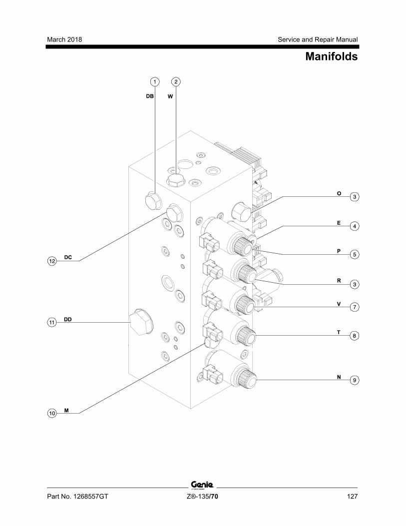
March 2018 Service and Repair Manual
Manifolds
Part No. 1268557GT Z®-135/70 127
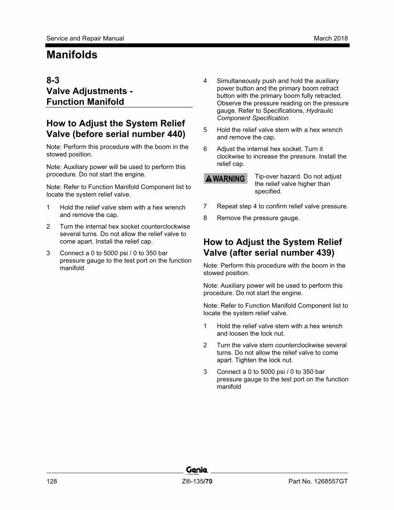
Service and Repair Manual March 2018
Manifolds
128 Z®-135/70 Part No. 1268557GT
8-3 Valve Adjustments - Function Manifold
How to Adjust the System Relief Valve (before serial number 440) Note: Perform this procedure with the boom in the stowed position.
Note: Auxiliary power will be used to perform this procedure. Do not start the engine.
Note: Refer to Function Manifold Component list to locate the system relief valve.
1 Hold the relief valve stem with a hex wrench and remove the cap.
2 Turn the internal hex socket counterclockwise several turns. Do not allow the relief valve to come apart. Install the relief cap.
3 Connect a 0 to 5000 psi / 0 to 350 bar pressure gauge to the test port on the function manifold
4 Simultaneously push and hold the auxiliary power button and the primary boom retract button with the primary boom fully retracted. Observe the pressure reading on the pressure gauge. Refer to Specifications, Hydraulic Component Specification.
5 Hold the relief valve stem with a hex wrench and remove the cap.
6 Adjust the internal hex socket. Turn it clockwise to increase the pressure. Install the relief cap.
Tip-over hazard. Do not adjust the relief valve higher than specified.
7 Repeat step 4 to confirm relief valve pressure.
8 Remove the pressure gauge. How to Adj ust the System Reli ef Valve
How to Adjust the System Relief Valve (after serial number 439) Note: Perform this procedure with the boom in the stowed position.
Note: Auxiliary power will be used to perform this procedure. Do not start the engine.
Note: Refer to Function Manifold Component list to locate the system relief valve.
1 Hold the relief valve stem with a hex wrench and loosen the lock nut.
2 Turn the valve stem counterclockwise several turns. Do not allow the relief valve to come apart. Tighten the lock nut.
3 Connect a 0 to 5000 psi / 0 to 350 bar pressure gauge to the test port on the function manifold

March 2018 Service and Repair Manual
Manifolds
Part No. 1268557GT Z®-135/70 129
4 Simultaneously push and hold the auxiliary power button and the primary boom retract button with the primary boom fully retracted. Observe the pressure reading on the pressure gauge. Refer to Specifications, Hydraulic Component Specification.
5 Hold the relief valve stem with a hex wrench and loosen the lock nut.
6 Adjust the valve stem. Turn it clockwise to increase the pressure. Tighten the lock nut.
Tip-over hazard. Do not adjust the relief valve higher than specified.
7 Repeat step 4 to confirm relief valve pressure.
8 Remove the pressure gauge.
How to Adj ust the Primary Boom Ex tend R elief Valve
How to Adjust the Primary Boom Extend Relief Valve Note: Perform this procedure with the axles extended.
1 Remove the primary boom end cover from the pivot end of the boom.
2 Locate the primary boom extend limit switch on the side of the primary boom.
3 Follow the wiring from the switch to the pivot end of the primary boom. Locate and disconnect the wire connector for the primary boom extend limit switch.
Note: The correct wire connector will be a 2 pin connector with a yellow marker on the cable.
4 Start the engine and fully extend the primary boom. Turn the engine off.
5 Connect a 0 to 5000 psi / 0 to 350 bar pressure gauge to the ptest port on the function manifold.
6 Start the engine from the ground controls and press and release the rpm select button until the engine changes to high idle.
Service and Repair Manual March 2018
Manifolds
130 Z®-135/70 Part No. 1268557GT
7 Simultaneously push and hold the function enable/high speed button and the primary boom extend button with the primary boom fully extended. Observe the pressure reading on the pressure gauge. Refer to Specifications, Hydraulic Component Specifications.
8 Turn the engine off. Use a wrench to hold the relief valve and remove the cap.
9 Adjust the internal hex socket. Turn it clockwise to increase the pressure or counterclockwise to decrease the pressure. Install the relief valve cap.
Tip-over hazard. Do not adjust the relief valve higher than specified.
10 Repeat step 7 to confirm relief valve pressure.
11 At the pivot end of the primary boom, connect the primary boom extend limit switch connector, that was disconnected in step 3.
12 Install the primary boom end cover.
13 Remove the pressure gauge.
14 Start the engine and fully retract the primary boom. Turn the engine off.

March 2018 Service and Repair Manual
Manifolds
Part No. 1268557GT Z®-135/70 131
8-4 Platform Manifold The platform manifold is mounted to the platform mounting weldment.
Index No. Description Schematic
Item Function Torque
1 Solenoid valve, 3 position 4 way AH Platform rotate left/right 20-25 ft-lbs / 27-34 Nm
2 Proportional solenoid valve, 3 position 4 way AI Platform level up/down 20-25 ft-lbs / 27-34 Nm
3 Flow control valve,0.2 gpm / 0.76 L/min AG Platform rotate left/right circuit 20-25 ft-lbs / 27-34 Nm

Service and Repair Manual March 2018
Manifolds
132 Z®-135/70 Part No. 1268557GT
8-5 Jib Boom Manifold The jib boom manifold is mounted inside the primary extension boom at the platform end.
Index No. Description Schematic
Item Function Torque
1 Pressure compensator valve, 150 psi / 10.3 bar
X Jib boom up/down circuit, regulates pressure drop across jib boom up/down proportional valve
30-35 ft-lbs / 41-47 Nm
2 Solenoid Valve, 2 position 3 way AE Jib boom retract 20-25 ft-lbs / 27-34 Nm
3 Solenoid Valve, 2 position 3 way AD Jib boom extend 20-25 ft-lbs / 27-34 Nm 4 Flow regulator valve, 2 gpm / 7.6
L/min AC Jib boom extend/retract circuit 20-25 ft-lbs / 27-34 Nm
5 Orifice, 0.040 inch / 1 mm AB Jib boom extend/retract circuit 6 Check valve, 25 psi / 1.7 bar AA Holds oil in jib boom manifold 20-25 ft-lbs / 27-34 Nm 7 Shuttle valve Z Jib boom up/down circuit 10-12 ft-lbs / 14-16 Nm 8 Proportional solenoid valve,
3 position 4 way Y Jib boom up/down 20-25 ft-lbs / 27-34 Nm
9 Proportional solenoid valve, 3 position 4 way
AF Jib boom bellcrank level up/down
20-25 ft-lbs / 27-34 Nm
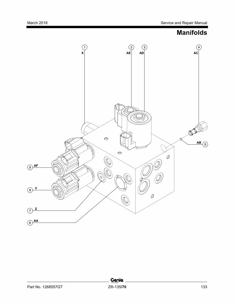
March 2018 Service and Repair Manual
Manifolds
Part No. 1268557GT Z®-135/70 133
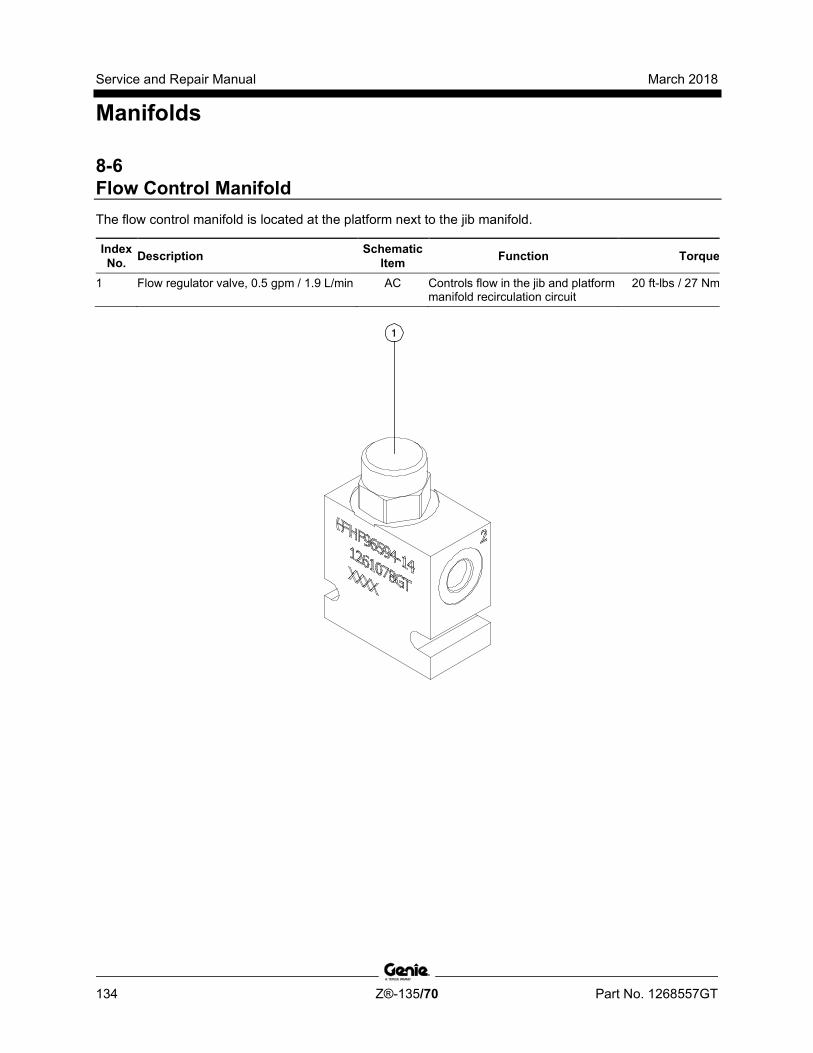
Service and Repair Manual March 2018
Manifolds
134 Z®-135/70 Part No. 1268557GT
8-6 Flow Control Manifold The flow control manifold is located at the platform next to the jib manifold.
Index No. Description Schematic
Item Function Torque
1 Flow regulator valve, 0.5 gpm / 1.9 L/min AC Controls flow in the jib and platform manifold recirculation circuit
20 ft-lbs / 27 Nm

March 2018 Service and Repair Manual
Manifolds
Part No. 1268557GT Z®-135/70 135
8-7 Function Enable Valve The function enable valve is mounted behind the medium pressure filter.
Index No. Description Schematic
Item Function Torque
1 Solenoid valve, 2 position 2 way A Enables lift pump to provide hydraulic pressure for all boom and steer/axle functions
20-25 ft-lbs / 27-34 Nm
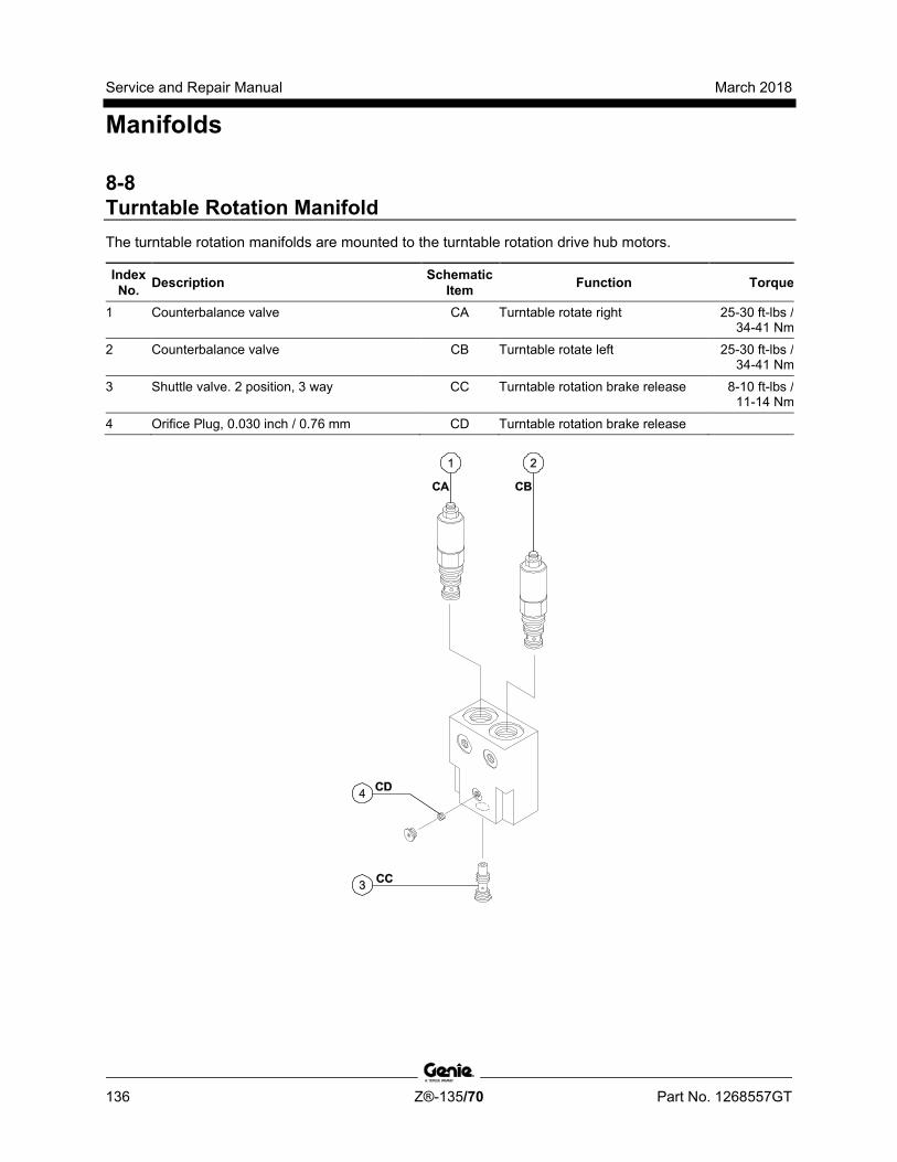
Service and Repair Manual March 2018
Manifolds
136 Z®-135/70 Part No. 1268557GT
8-8 Turntable Rotation Manifold The turntable rotation manifolds are mounted to the turntable rotation drive hub motors.
Index No. Description Schematic
Item Function Torque
1 Counterbalance valve CA Turntable rotate right 25-30 ft-lbs / 34-41 Nm
2 Counterbalance valve CB Turntable rotate left 25-30 ft-lbs / 34-41 Nm
3 Shuttle valve. 2 position, 3 way CC Turntable rotation brake release 8-10 ft-lbs / 11-14 Nm
4 Orifice Plug, 0.030 inch / 0.76 mm CD Turntable rotation brake release

March 2018 Service and Repair Manual
Part No. 1268557GT Z®-135/70 137
This page intentionally left blank.

Service and Repair Manual March 2018
Manifolds
138 Z®-135/70 Part No. 1268557GT
8-9 Steer and Axle Manifold The steer and axle manifold is mounted inside the manifold box at the yellow triangle side of the machine.
Index No. Description Schematic
Item Function Torque
1 Flow control valve, 1.5 gpm / 5.7 L/min BI Right front steer cylinder retract circuit
20-25 ft-lbs / 27-34 Nm
2 Check valve BC Prevents right front steer cylinder from moving when not steering
20-25 ft-lbs / 27-34 Nm
3 Check valve BB Prevents left front steer cylinder from moving when not steering
20-25 ft-lbs / 27-34 Nm
4 Flow regulator valve, 2.1 gpm / 8 L/min BL Right rear steer cylinder extend circuit
20-25 ft-lbs / 27-34 Nm
5 Solenoid valve, 3 position 4 way BQ Steer left/right, right rear steer cylinder
20-25 ft-lbs / 27-34 Nm
6 Check valve BE Prevents right rear steer cylinder from moving when not steering
20-25 ft-lbs / 27-34 Nm
7 Check valve BD Prevents right rear steer cylinder from moving when not steering
20-25 ft-lbs / 27-34 Nm
8 Solenoid valve, 3 position 4 way BP Steer left/right, left rear steer cylinder
20-25 ft-lbs / 27-34 Nm
9 Flow regulator valve, 2.1 gpm / 8 L/min BJ Left rear steer cylinder extend circuit
20-25 ft-lbs / 27-34 Nm
10 Flow regulator valve, 7 gpm / 26.5 L/min BS Axle extend/retract circuit 20-25 ft-lbs / 27-34 Nm
11 Solenoid Valve, 2 position 3 way BU Axle retract 30-35 ft-lbs / 41-47 Nm
12 Solenoid Valve, 2 position 3 way BT Axle extend 30-35 ft-lbs / 41-47 Nm
13 Pressure reducing valve BR Axle extend/retract circuit 30-35 ft-lbs / 41-47 Nm

March 2018 Service and Repair Manual
Manifolds
Part No. 1268557GT Z®-135/70 139

Service and Repair Manual March 2018
Manifolds
140 Z®-135/70 Part No. 1268557GT
Steer and Axle Manifold, continued The steer and axle manifold is mounted inside the manifold box at the yellow triangle side of the machine.
Index No. Description Schematic
Item Function Torque
14 Flow regulator valve, 1.5 gpm / 5.7 L/min BK Left rear steer cylinder retract circuit
20-25 ft-lbs / 27-34 Nm
15 Flow regulator valve, 1.5 gpm / 5.7 L/min BM Right rear steer cylinder retract circuit
20-25 ft-lbs / 27-34 Nm
16 Flow regulator valve, 1.5 gpm / 5.7 L/min BG Left front steer cylinder retract circuit
20-25 ft-lbs / 27-34 Nm
17 Flow regulator valve, 2.1 gpm / 8 L/min BF Left front steer cylinder extend circuit
20-25 ft-lbs / 27-34 Nm
18 Flow regulator valve, 2.1 gpm / 8 L/min BH Right front steer cylinder extend circuit
20-25 ft-lbs / 27-34 Nm
19 Solenoid valve, 3 position 4 way BN Steer left/right, left front steer cylinder
20-25 ft-lbs / 27-34 Nm
20 Solenoid valve, 3 position 4 way BO Steer left/right, right front steer cylinder
20-25 ft-lbs / 27-34 Nm
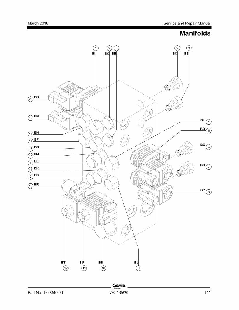
March 2018 Service and Repair Manual
Manifolds
Part No. 1268557GT Z®-135/70 141

Service and Repair Manual March 2018
Manifolds
142 Z®-135/70 Part No. 1268557GT
8-10 Valve Adjustments - Steer and Axle Manifold
How to Adjust the Axle Relief Valve Note: Perform this procedure with the machine on a firm, level surface and in the stowed position with the axles extended.
Note: Refer to Steer and Axle Manifold list to locate the axle relief valve.
Note: Two people will be required to perform this procedure.
1 Connect a 0 to 5000 psi / 0 to 350 bar pressure gauge to the test port on the steer and axle manifold.
2 Locate the axle relief valve on the steer and axle manifold. Hold the relief valve with a wrench and remove the cap.
3 Start the engine from the platform controls and press down the foot switch. Press and hold the axle extend button at the platform controls. Observe the pressure reading on the pressure gauge. Refer to Specifications, Hydraulic Component Specifications.
4 Turn the engine off.
5 Adjust the internal hex socket. Turn it clockwise to increase the pressure or counterclockwise to decrease the pressure. Install the relief valve cap.
Component damage hazard. Do not adjust the relief valve pressures higher than specifications.
6 Repeat steps 3 through 5 to confirm relief valve pressure.
7 Remove the pressure gauge.

March 2018 Service and Repair Manual
Part No. 1268557GT Z®-135/70 143
This page intentionally left blank.
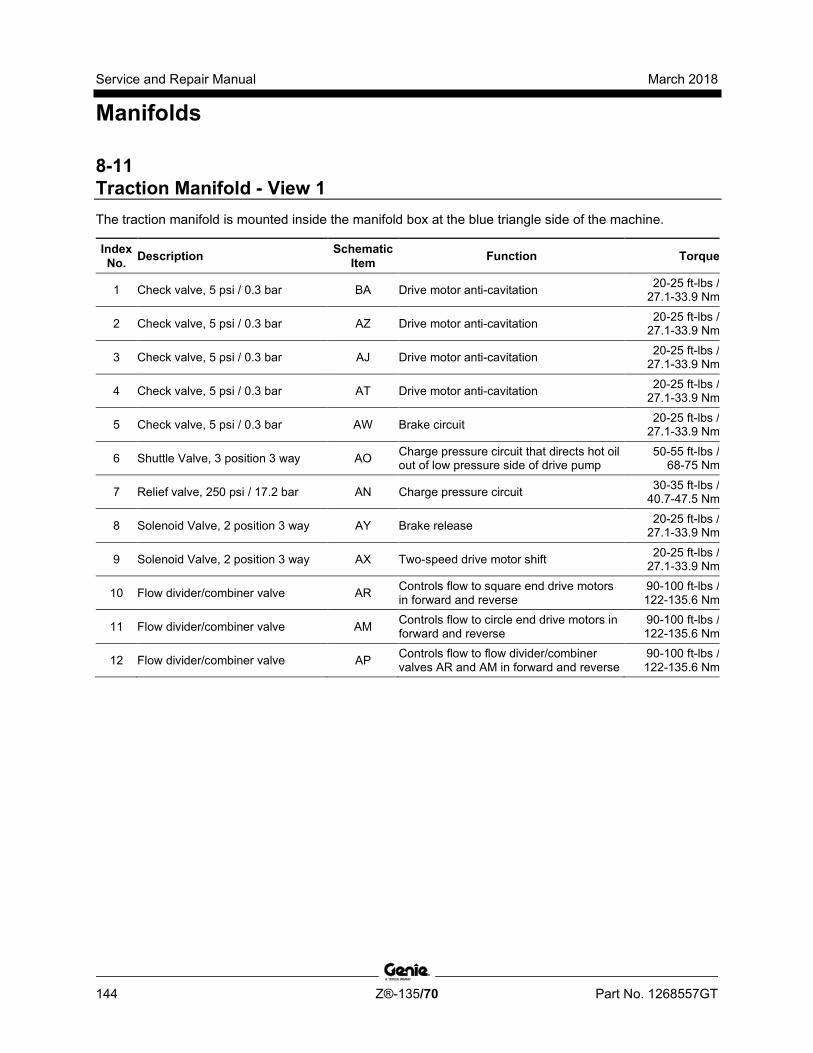
Service and Repair Manual March 2018
Manifolds
144 Z®-135/70 Part No. 1268557GT
8-11 Traction Manifold - View 1 The traction manifold is mounted inside the manifold box at the blue triangle side of the machine.
Index No. Description Schematic
Item Function Torque
1 Check valve, 5 psi / 0.3 bar BA Drive motor anti-cavitation 20-25 ft-lbs / 27.1-33.9 Nm
2 Check valve, 5 psi / 0.3 bar AZ Drive motor anti-cavitation 20-25 ft-lbs / 27.1-33.9 Nm
3 Check valve, 5 psi / 0.3 bar AJ Drive motor anti-cavitation 20-25 ft-lbs / 27.1-33.9 Nm
4 Check valve, 5 psi / 0.3 bar AT Drive motor anti-cavitation 20-25 ft-lbs / 27.1-33.9 Nm
5 Check valve, 5 psi / 0.3 bar AW Brake circuit 20-25 ft-lbs / 27.1-33.9 Nm
6 Shuttle Valve, 3 position 3 way AO Charge pressure circuit that directs hot oil out of low pressure side of drive pump
50-55 ft-lbs / 68-75 Nm
7 Relief valve, 250 psi / 17.2 bar AN Charge pressure circuit 30-35 ft-lbs / 40.7-47.5 Nm
8 Solenoid Valve, 2 position 3 way AY Brake release 20-25 ft-lbs / 27.1-33.9 Nm
9 Solenoid Valve, 2 position 3 way AX Two-speed drive motor shift 20-25 ft-lbs / 27.1-33.9 Nm
10 Flow divider/combiner valve AR Controls flow to square end drive motors in forward and reverse
90-100 ft-lbs / 122-135.6 Nm
11 Flow divider/combiner valve AM Controls flow to circle end drive motors in forward and reverse
90-100 ft-lbs / 122-135.6 Nm
12 Flow divider/combiner valve AP Controls flow to flow divider/combiner valves AR and AM in forward and reverse
90-100 ft-lbs / 122-135.6 Nm
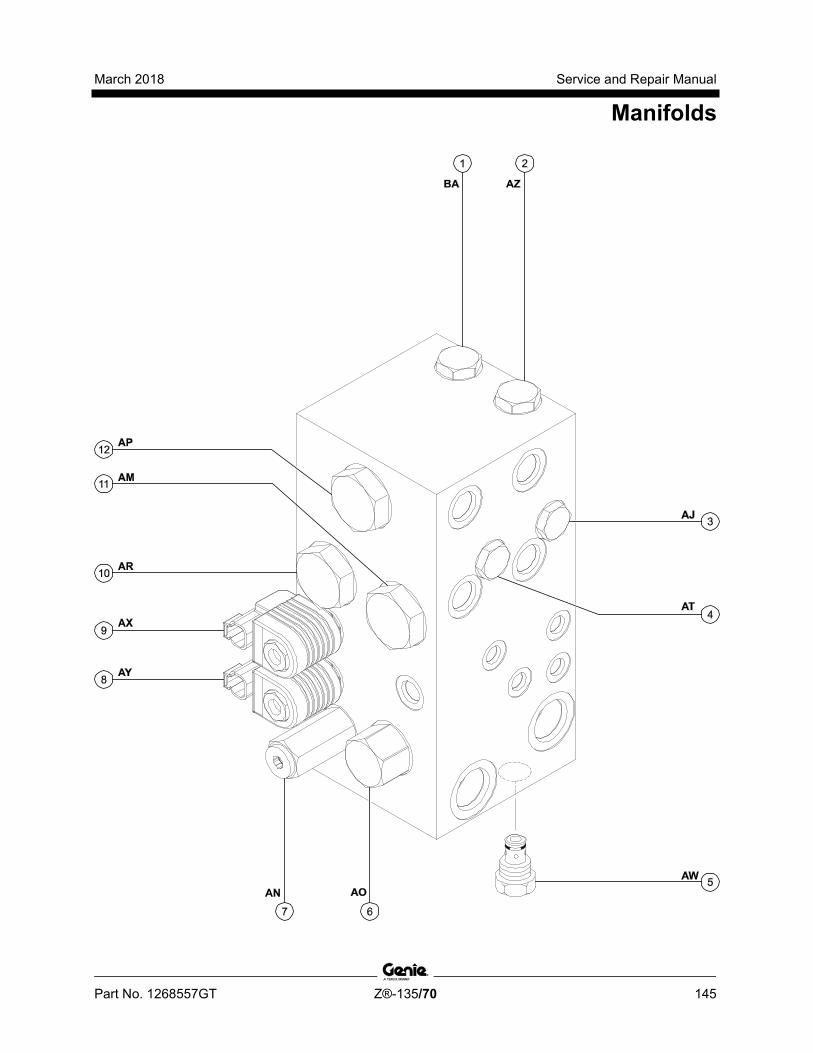
March 2018 Service and Repair Manual
Manifolds
Part No. 1268557GT Z®-135/70 145
Service and Repair Manual March 2018
Manifolds
146 Z®-135/70 Part No. 1268557GT
Traction Manifold - View 2 Index No. Description Schematic
Item Function Torque
1
Orifice, 0.063 in / 1.6 mm (before serial number 180 except for serial number 102)
AL Equalizes pressure on both sides of divider/combiner valve AM
- Orifice, 0.039 in / 1 mm (serial number 102 and after serial number 179)
AL Equalizes pressure on both sides of divider/combiner valve AM
2 Orifice, 0.052 in / 1.3 mm AQ Equalizes pressure on both sides of divider/combiner valve AP
3 Orifice, 0.063 in / 1.6 mm AS Equalizes pressure on both sides of divider/combiner valve AR
4 Orifice, 0.030 in / 0.76 mm AV Brake and two-speed circuit
5 Check valve, 5 psi / 0.3 bar AU Drive motor anti-cavitation 20-25 ft-lbs / 27-34 Nm
6 Check valve, 5 psi / 0.3 bar AK Drive motor anti-cavitation 20-25 ft-lbs / 27-34 Nm

March 2018 Service and Repair Manual
Manifolds
Part No. 1268557GT Z®-135/70 147
Service and Repair Manual March 2018
Manifolds
148 Z®-135/70 Part No. 1268557GT
8-12 Valve Adjustments - Traction Manifold
How to Adjust the Hot Oil Relief Valve Note: The hydraulic oil temperature must be 100°F to 150°F / 38°C to 65.5°C before performing this procedure.
1 Connect a 0 to 600 psi / 0 to 50 bar pressure gauge to either the "A" or "B" test port on the drive pump.
2 Locate the hot oil relief valve on the traction manifold. Hold the relief valve and remove the cap.
3 Turn the internal hex socket clockwise fully until it stops. Install the cap.
4 Start the engine from the ground controls.
5 Press and hold the function enable/high rpm select button (rabbit symbol) position. Note the reading on the pressure gauge.
6 Turn the engine off.
7 Remove the pressure gauge from the drive pump. Connect the gauge to the test port located on the traction manifold.
8 Hold the hot oil relief valve and remove the cap.
9 Start the engine from the ground controls.
10 Press and hold the function enable/high rpm select button (rabbit symbol) position.
11 Adjust the internal hex socket until the pressure reading on the gauge is 40 psi / 2.8 bar less than the pressure reading on the pump. Turn it clockwise to increase the pressure or counterclockwise to decrease the pressure. Install the relief valve cap.
12 Turn the engine off.
13 Remove the pressure gauge.
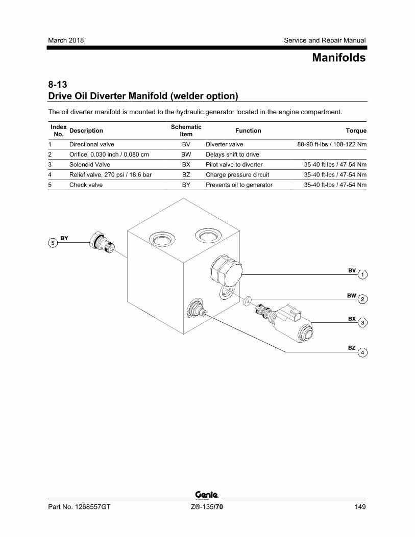
March 2018 Service and Repair Manual
Manifolds
Part No. 1268557GT Z®-135/70 149
8-13 Drive Oil Diverter Manifold (welder option) The oil diverter manifold is mounted to the hydraulic generator located in the engine compartment.
Index No. Description Schematic
Item Function Torque
1 Directional valve BV Diverter valve 80-90 ft-lbs / 108-122 Nm 2 Orifice, 0.030 inch / 0.080 cm BW Delays shift to drive 3 Solenoid Valve BX Pilot valve to diverter 35-40 ft-lbs / 47-54 Nm
4 Relief valve, 270 psi / 18.6 bar BZ Charge pressure circuit 35-40 ft-lbs / 47-54 Nm 5 Check valve BY Prevents oil to generator 35-40 ft-lbs / 47-54 Nm
Service and Repair Manual March 2018
Manifolds
150 Z®-135/70 Part No. 1268557GT
8-14 Valve Coils
How to Test a Coil A properly functioning coil provides an electromotive force which operates the solenoid valve. Critical to normal operation is continuity within the coil that provides this force field.
Since coil resistance is sensitive to temperature, resistance values outside specification can produce erratic operation. When coil resistance decreases below specification, amperage increases. As resistance rises above specification, voltage increases.
While valves may operate when coil resistance is outside specification, maintaining coils within specification will help ensure proper valve function over a wide range of operating temperatures.
Electrocution/burn hazard. Contact with electrically charged circuits could result in death or serious injury. Remove all rings, watches and other jewelry.
1 Tag and disconnect the wiring from the coil to be tested.
2 Test the coil resistance.
Result: The resistance should be within specification, plus or minus 30%.
Result: If the resistance is not within specification, plus or minus 30%, replace the coil.
Valve Coil Resistance Specification Note: The following coil resistance specifications are at an ambient temperature of 68°F / 20°C. As valve coil resistance is sensitive to changes in air temperature, the coil resistance will typically increase or decrease by 4% for each 18°F / 10°C that your air temperature increases or decreases from 68°F / 20°C.
Valve Coil Resistance Specification Proportional solenoid valve (schematic items N, P, R, T, V)
3.5 to 5.5Ω
Solenoid valve, 3 position 4 way (schematic item B)
4 to 6Ω
Solenoid valve, 3 position 4 way (schematic items BN, BO, BP, BQ)
7 to 9Ω
Solenoid valve, 3 position 4 way (schematic item AH )
8 to 10Ω
Proportional solenoid valve, 3 position 4 way (schematic items Y, AI)
8 to 10Ω
Solenoid Valve, 2 position 3 way (schematic items F, AD)
5.5 to 7.5Ω
Solenoid Valve, 2 position 3 way (schematic item AE, AF)
8 to 10Ω
Solenoid Valve, 2 position 3 way (schematic items H, J)
3.5 to 5.5Ω
Solenoid Valve, 2 position 3 way (schematic items C, D, G, I, K, AX, AY, BU, BT)
7.5 to 9.5Ω
Solenoid valve, 2 position 2 way (schematic item A)
3.5 to 5.5Ω

March 2018 Service and Repair Manual
Manifolds
Part No. 1268557GT Z®-135/70 151
How to Test a Coil Diode Properly functioning coil diodes protect the electrical circuit by suppressing voltage spikes. Voltage spikes naturally occur within a function circuit following the interruption of electrical current to a coil. Faulty diodes can fail to protect the electrical system, resulting in a tripped circuit breaker or component damage.
Electrocution/burn hazard. Contact with electrically charged circuits could result in death or serious injury. Remove all rings, watches and other jewelry.
1 Test the coil for resistance. Refer to Repair Procedure, How to Test a Coil.
2 Connect a 10W resistor to the negative terminal of a known good 9V DC battery. Connect the other end of the resistor to a terminal on the coil.
Resistor 10Ω Genie part number 27287
Note: The battery should read 9V DC or more when measured across the terminals.
1 multimeter 2 9v DC battery 3 10Ω resistor 4 coil
Note: Dotted lines in illustration indicate a reversed connection as specified in step 6.
3 Set a multimeter to read DC current.
Note: The multimeter, when set to read DC current, should be capable of reading up to 800 mA.
4 Connect the negative lead to the other terminal on the coil.
5 Momentarily connect the positive lead from the multimeter to the positive terminal on the 9V DC battery. Note and record the current reading.
6 At the battery or coil terminals, reverse the connections. Note and record the current reading.
Result: Both current readings are greater than 0 mA and are different by a minimum of 20%. The coil is good.
Result: If one or both of the current readings are 0 mA, or if the two current readings do not differ by a minimum of 20%, the coil and/or its internal diode are faulty and the coil should be replaced.
Service and Repair Manual March 2018
Turntable Rotation Components
152 Z®-135/70 Part No. 1268557GT
9-1 Turntable Rotation Assembly
How to Remove a Turntable Rotation Assembly Note: When removing a hose assembly or fitting, the O-ring (if equipped) on the fitting and/or hose end must be replaced. All connections must be torqued to specification during installation. Refer to Specifications, Hydraulic Hose and Fitting Torque Specifications.
Note: Perform this procedure with the primary boom between the circle-end tires and with the machine on a firm, level surface.
1 Secure the turntable from rotating with the turntable rotation lock pin.
2 Remove the ground controls side fixed turntable cover.
3 Tag, disconnect the hydraulic hoses from the turntable rotation motor. Cap the fittings on the motor.
Bodily injury hazard. Spraying hydraulic oil can penetrate and burn skin. Loosen hydraulic connections very slowly to allow the oil pressure to dissipate gradually. Do not allow oil to squirt or spray.
4 Attach a lifting strap from an overhead crane or other suitable lifting device to the lifting eye on the turntable rotation assembly.
5 Remove the drive hub mounting bolts and remove the turntable rotation assembly from the machine.
6 Repeat steps 3 through 5 for the other turntable rotation assembly.
Tip-over hazard. If the turntable rotation lock pin is not properly installed, machine stability is compromised and the machine could tip over when the drive hub is removed from the machine, which could result in death or serious injury.
Crushing hazard. The drive hub could become unbalanced and fall if not properly supported by an overhead crane or lifting device when removed from the machine.
Note: When installing a turntable rotation assembly, the rotation gear backlash must be adjusted. Refer to Repair Procedure, Adjust the Turntable Rotation Gear Backlash.
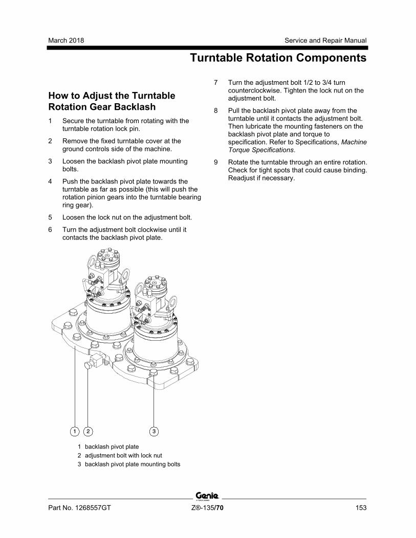
March 2018 Service and Repair Manual
Turntable Rotation Components
Part No. 1268557GT Z®-135/70 153
How to Adj ust the Tur ntabl e R otati on Gear Backlash
How to Adjust the Turntable Rotation Gear Backlash 1 Secure the turntable from rotating with the
turntable rotation lock pin.
2 Remove the fixed turntable cover at the ground controls side of the machine.
3 Loosen the backlash pivot plate mounting bolts.
4 Push the backlash pivot plate towards the turntable as far as possible (this will push the rotation pinion gears into the turntable bearing ring gear).
5 Loosen the lock nut on the adjustment bolt.
6 Turn the adjustment bolt clockwise until it contacts the backlash pivot plate.
1 backlash pivot plate 2 adjustment bolt with lock nut 3 backlash pivot plate mounting bolts
7 Turn the adjustment bolt 1/2 to 3/4 turn counterclockwise. Tighten the lock nut on the adjustment bolt.
8 Pull the backlash pivot plate away from the turntable until it contacts the adjustment bolt. Then lubricate the mounting fasteners on the backlash pivot plate and torque to specification. Refer to Specifications, Machine Torque Specifications.
9 Rotate the turntable through an entire rotation. Check for tight spots that could cause binding. Readjust if necessary.
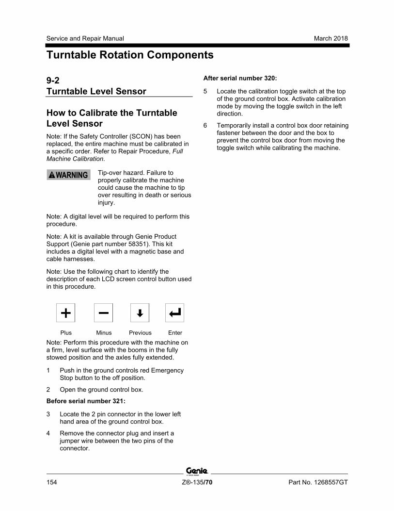
Service and Repair Manual March 2018
Turntable Rotation Components
154 Z®-135/70 Part No. 1268557GT
9-2 Turntable Level Sensor
How to Calibrate the Turntable Level Sensor Note: If the Safety Controller (SCON) has been replaced, the entire machine must be calibrated in a specific order. Refer to Repair Procedure, Full Machine Calibration.
Tip-over hazard. Failure to properly calibrate the machine could cause the machine to tip over resulting in death or serious injury.
Note: A digital level will be required to perform this procedure.
Note: A kit is available through Genie Product Support (Genie part number 58351). This kit includes a digital level with a magnetic base and cable harnesses.
Note: Use the following chart to identify the description of each LCD screen control button used in this procedure.
Plus Minus Previous Enter
Note: Perform this procedure with the machine on a firm, level surface with the booms in the fully stowed position and the axles fully extended.
1 Push in the ground controls red Emergency Stop button to the off position.
2 Open the ground control box.
Before serial number 321:
3 Locate the 2 pin connector in the lower left hand area of the ground control box.
4 Remove the connector plug and insert a jumper wire between the two pins of the connector.
After serial number 320:
5 Locate the calibration toggle switch at the top of the ground control box. Activate calibration mode by moving the toggle switch in the left direction.
6 Temporarily install a control box door retaining fastener between the door and the box to prevent the control box door from moving the toggle switch while calibrating the machine.

March 2018 Service and Repair Manual
Turntable Rotation Components
Part No. 1268557GT Z®-135/70 155
All models:
7 Turn the key switch to ground controls.
8 Remove the key from the main key switch. Insert the key into the bypass/recovery key switch and turn it to the bypass position.
Note: The angle sensor calibration values will not be saved correctly unless the key switch is in the bypass position and the calibration toggle switch is activated.
9 Press and hold the enter button on the ground control panel while pulling out the ground controls red Emergency Stop button to the on position. Hold the enter button for approximately 5 seconds and then release it.
10 Enter sensor calibration mode by pressing the buttons at the ground controls in the following sequence: (plus)(enter)(enter)(plus).
1 Run 2 Bypass 3 Recovery
Note: The bypass/recovery key switch is located on the lower right side of the control box from serial number Z13512-1712.
11 Press the enter or previous button on the LCD screen until SET UNIT X AXIS LEVEL TO GRAVITY is displayed.
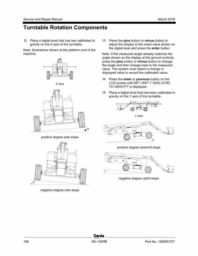
Service and Repair Manual March 2018
Turntable Rotation Components
156 Z®-135/70 Part No. 1268557GT
12 Place a digital level that has ben calibrated to gravity on the X axis of the turntable.
Note: Illustrations shown at the platform end of the machine.
X axis
positive degree side slope
negative degree side slope
13 Press the plus button or minus button to adjust the display to the exact value shown on the digital level and press the enter button.
Note: If the measured angle already matches the angle shown on the display at the ground controls, press the plus button or minus button to change the angle and then change back to the measured value. The system must detect a change in displayed value to record the calibrated value.
14 Press the enter or previous button on the LCD screen,until SET UNIT Y AXIS LEVEL TO GRAVITY is displayed.
15 Place a digital level that has been calibrated to gravity on the Y axis of the turntable.
Y axis
positive degree downhill slope
negative degree uphill slope
March 2018 Service and Repair Manual
Turntable Rotation Components
Part No. 1268557GT Z®-135/70 157
16 Press the plus button or minus button to adjust the display to the exact value shown on the digital level and press the enter button.
Note: If the measured angle already matches the angle shown on the display at the ground controls, press the plus button or minus button to change the angle and then change back to the measured value. The system must detect a change in displayed value to record the calibrated value.
17 Press the enter or previous button on the LCD screen until EXIT is displayed.
18 Press the plus button to select YES, then press the enter button to accept.
19 Turn the key back to the run position and remove the key from the bypass/recovery key switch. Insert the key into the main key switch and turn it to ground controls.
Note: Be sure that the bypass/recovery key switch is in the run position before attempting to operate the machine.
20 Wait approximately 20 seconds and turn the machine off by pressing the red Emergency Stop button in.
Before serial number 321:
21 Remove the wire jumper from the 2 pin connector in the lower left hand area of the ground control box that was installed in step 4. Install the connector plug.
Tip-over hazard. Failure to remove the jumper wire will result in an unsafe configuration which will compromise machine stability. Operating the machine in this configuration will result in the machine tipping over, resulting in death or serious injury. The jumper wire must be removed before operating the machine.
22 Close the ground control box and install the door retaining fasteners.
After serial number 320:
23 Remove the fastener that was temporarily installed. Close the control box door and install the door retaining fasteners.
Note: When the control box door is closed, the calibration toggle switch is automatically activated to exit out of calibration mode.
All models:
24 Start the engine. Be sure there are no calibration faults shown on the display.
25 Perform level sensor test. Refer to Maintenance Procedure, Test the Level Sensor.
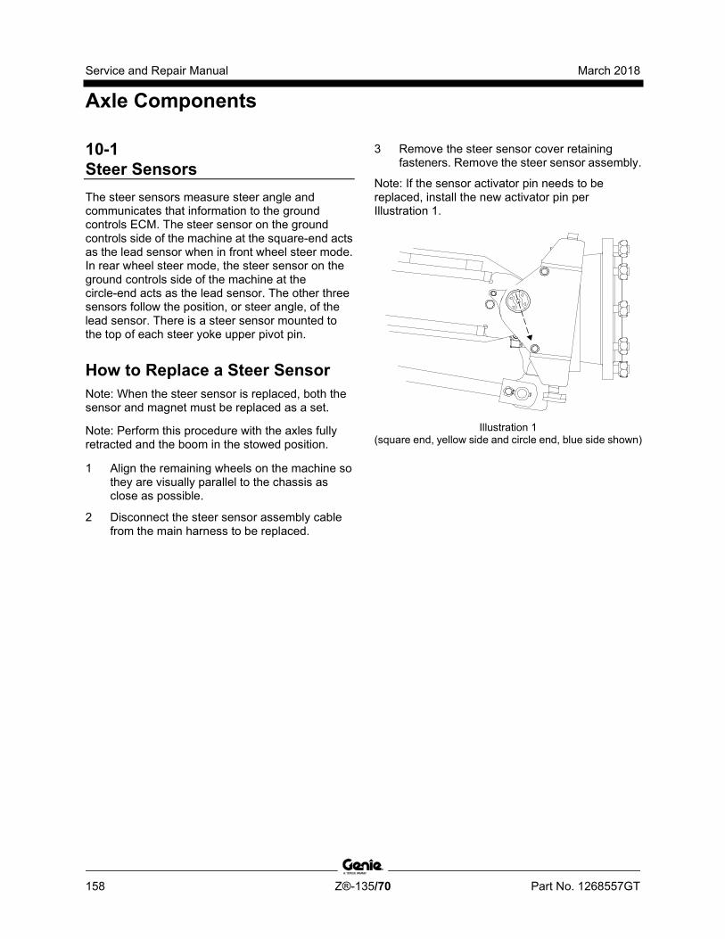
Service and Repair Manual March 2018
Axle Components
158 Z®-135/70 Part No. 1268557GT
10-1 Steer Sensors The steer sensors measure steer angle and communicates that information to the ground controls ECM. The steer sensor on the ground controls side of the machine at the square-end acts as the lead sensor when in front wheel steer mode. In rear wheel steer mode, the steer sensor on the ground controls side of the machine at the circle-end acts as the lead sensor. The other three sensors follow the position, or steer angle, of the lead sensor. There is a steer sensor mounted to the top of each steer yoke upper pivot pin.
How to Replace a Steer Sensor Note: When the steer sensor is replaced, both the sensor and magnet must be replaced as a set.
Note: Perform this procedure with the axles fully retracted and the boom in the stowed position.
1 Align the remaining wheels on the machine so they are visually parallel to the chassis as close as possible.
2 Disconnect the steer sensor assembly cable from the main harness to be replaced.
3 Remove the steer sensor cover retaining fasteners. Remove the steer sensor assembly.
Note: If the sensor activator pin needs to be replaced, install the new activator pin per Illustration 1.
Illustration 1 (square end, yellow side and circle end, blue side shown)
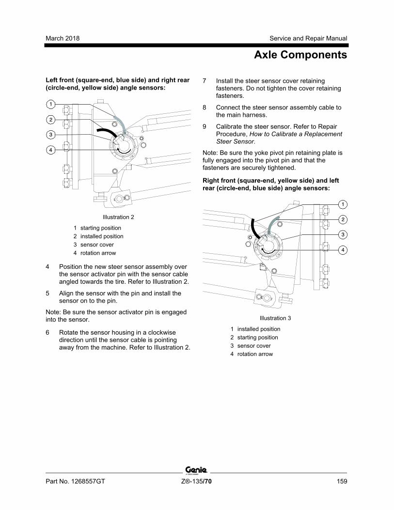
March 2018 Service and Repair Manual
Axle Components
Part No. 1268557GT Z®-135/70 159
Left front (square-end, blue side) and right rear (circle-end, yellow side) angle sensors:
Illustration 2
1 starting position 2 installed position 3 sensor cover 4 rotation arrow
4 Position the new steer sensor assembly over the sensor activator pin with the sensor cable angled towards the tire. Refer to Illustration 2.
5 Align the sensor with the pin and install the sensor on to the pin.
Note: Be sure the sensor activator pin is engaged into the sensor.
6 Rotate the sensor housing in a clockwise direction until the sensor cable is pointing away from the machine. Refer to Illustration 2.
7 Install the steer sensor cover retaining fasteners. Do not tighten the cover retaining fasteners.
8 Connect the steer sensor assembly cable to the main harness.
9 Calibrate the steer sensor. Refer to Repair Procedure, How to Calibrate a Replacement Steer Sensor.
Note: Be sure the yoke pivot pin retaining plate is fully engaged into the pivot pin and that the fasteners are securely tightened.
Right front (square-end, yellow side) and left rear (circle-end, blue side) angle sensors:
Illustration 3
1 installed position 2 starting position 3 sensor cover 4 rotation arrow

Service and Repair Manual March 2018
Axle Components
160 Z®-135/70 Part No. 1268557GT
10 Position the new steer sensor assembly over the sensor activator pin with the sensor cable angled away from the tire. Refer to Illustration 3.
11 Align the sensor with the pin and install the sensor on to the pin.
Note: Be sure the sensor activator pin is engaged into the sensor.
12 Rotate the sensor housing in a clockwise direction until the sensor cable is pointing away from the machine. Refer to Illustration 2.
13 Install the steer sensor cover retaining fasteners. Do not tighten the cover retaining fasteners.
14 Connect the steer sensor assembly cable to the main harness.
15 Calibrate the steer sensor. Refer to Repair Procedure, How to Calibrate a Replacement Steer Sensor.
Note: Be sure the yoke pivot pin retaining plate is fully engaged into the pivot pin and that the fasteners are securely tightened.
How to C alibr ate a R epl acem ent Steer Sensor
How to Calibrate a Replacement Steer Sensor Note: If a steer angle sensor has been removed or replaced, the steer angle sensors will need to be calibrated.
Note: Perform this procedure with the axles retracted and the tires straightened.
Note: Two people will be required to perform this procedure.
Note: Be sure the yoke pivot pin retaining plate is fully engaged into the pivot pin and that the fasteners are securely tightened.
1 Start the engine from the platform controls.
2 Select the proper steer mode. If a front (square-end) steer angle sensor has been replaced, select rear steer mode. If a rear (circle-end) steer angle sensor has been replaced, select front steer mode.
3 Have another person press down the foot switch.
4 At the new steer angle sensor, loosen the steer angle sensor cover retaining fasteners. Do not remove the fasteners or the sensor cover.
5 Rotate the sensor cover clockwise or counterclockwise until the tire is straight in relation with the other tires. Tighten the sensor cover fasteners.
Note: If available, WebGPI can also be used for this procedure.
6 Push in the red Emergency Stop button to the off position.
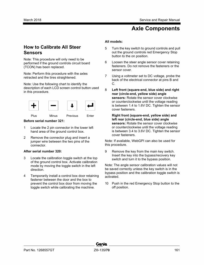
March 2018 Service and Repair Manual
Axle Components
Part No. 1268557GT Z®-135/70 161
How to C alibr ate All Steer Sensors
How to Calibrate All Steer Sensors Note: This procedure will only need to be performed if the ground controls circuit board (TCON) has been replaced.
Note: Perform this procedure with the axles retracted and the tires straightened.
Note: Use the following chart to identify the description of each LCD screen control button used in this procedure.
Plus Minus Previous Enter
Before serial number 321:
1 Locate the 2 pin connector in the lower left hand area of the ground control box.
2 Remove the connector plug and insert a jumper wire between the two pins of the connector.
After serial number 320:
3 Locate the calibration toggle switch at the top of the ground control box. Activate calibration mode by moving the toggle switch in the left direction.
4 Temporarily install a control box door retaining fastener between the door and the box to prevent the control box door from moving the toggle switch while calibrating the machine.
All models:
5 Turn the key switch to ground controls and pull out the ground controls red Emergency Stop button to the on position.
6 Loosen the steer angle sensor cover retaining fasteners. Do not remove the fasteners or the sensor cover.
7 Using a voltmeter set to DC voltage, probe the back of the electrical connector at pins B and C.
8 Left front (square-end, blue side) and right rear (circle-end, yellow side) angle sensors: Rotate the sensor cover clockwise or counterclockwise until the voltage reading is between 1.4 to 1.6V DC. Tighten the sensor cover fasteners.
Right front (square-end, yellow side) and left rear (circle-end, blue side) angle sensors: Rotate the sensor cover clockwise or counterclockwise until the voltage reading is between 3.4 to 3.6V DC. Tighten the sensor cover fasteners.
Note: If available, WebGPI can also be used for this procedure.
9 Remove the key from the main key switch. Insert the key into the bypass/recovery key switch and turn it to the bypass position.
Note: The angle sensor calibration values will not be saved correctly unless the key switch is in the bypass position and the calibration toggle switch is activated.
10 Push in the red Emergency Stop button to the off position.

Service and Repair Manual March 2018
Axle Components
162 Z®-135/70 Part No. 1268557GT
11 Press and hold the enter button on the ground control panel while pulling out the ground controls red Emergency Stop button to the on position. Hold the enter button for approximately 5 seconds and then release it.
1 Run 2 Bypass 3 Recovery
Note: The bypass/recovery key switch is located on the lower right side of the control box from serial number Z13512-1712.
12 Enter sensor calibration mode by pressing the buttons at the ground controls in the following sequence: (plus)(enter)(enter)(plus).
Delete all Steer Sensor Calibrations
13 Press the enter or previous button on the LCD screen until DELETE ALL STEER SENSORS CALIBRATION is displayed.Press the plus button to select YES, then press the enter button to accept.
Note: Models before software version 3.0, the LCD screen will display RESET ALL STEER SENSORS.
14 Press the enter or previous button on the LCD screen until EXIT is displayed.
15 Press the plus button to select YES, then press the enter button to accept.
16 Proceed to step 22.
Delete a Single Steer Sensor Calibration
17 To calibrate a single steer sensor, delete the specific steer sensor calibration
18 Press the enter or previous button on the LCD screen until DELETE _____ STEER SENSORS CALIBRATION is displayed. Example: DELETE BLUE END BLUE SIDE STEER SENSORS CALIBRATION (FL).
19 Press the plus button to select YES, then press the enter button to accept.
20 Press the enter or previous button on the LCD screen until EXIT is displayed.
21 Press the plus button to select YES, then press the enter button to accept.
March 2018 Service and Repair Manual
Axle Components
Part No. 1268557GT Z®-135/70 163
22 Push in the red Emergency Stop button to the off position.
Before serial number 321:
23 Remove the wire jumper from the 2 pin connector in the lower left hand area of the ground control box that was installed in step 2. Install the connector plug.
Tip-over hazard. Failure to remove the jumper wire will result in an unsafe configuration which will compromise machine stability. Operating the machine in this configuration will result in the machine tipping over, resulting in death or serious injury. The jumper wire must be removed before operating the machine.
24 Close the ground control box and install the door retaining fasteners.
After serial number 320:
25 Remove the fastener that was temporarily installed. Close the control box door and install the door retaining fasteners.
Note: When the control box door is closed, the calibration toggle switch is automatically activated to exit out of calibration mode.
All models:
26 Turn the key back to the run position and remove the key from the bypass/recovery key switch. Insert the key into the main key switch and turn it to ground controls.
Note: Be sure that the bypass/recovery key switch is in the run position before attempting to operate the machine.
10-2 Steer Cylinders
How to Remove a Steer Cylinder Note: When removing a hose assembly or fitting, the O-ring (if equipped) on the fitting and/or hose end must be replaced. All connections must be torqued to specification during installation. Refer to Specifications, Hydraulic Hose and Fitting Torque Specifications.
Note: Perform this procedure with the axles extended.
1 Tag, disconnect and plug the hydraulic hoses from the steer cylinder. Cap the fittings on the cylinder.
Bodily injury hazard. Spraying hydraulic oil can penetrate and burn skin. Loosen hydraulic connections very slowly to allow the oil pressure to dissipate gradually. Do not allow oil to squirt or spray.
2 Support the steer cylinder with a suitable lifting device. Protect the cylinder rod from damage.
3 Remove the pin retaining fasteners from both steer cylinder pivot pins.
4 Use a soft metal drift to remove the pins.
5 Remove the steering cylinder from the machine.
Crushing hazard. The steer cylinder may become unbalanced and fall if not properly supported by the lifting device when removed from the machine.
Service and Repair Manual March 2018
Axle Components
164 Z®-135/70 Part No. 1268557GT
10-3 Axle Extension Cylinders
How to Remove an Axle Extension Cylinder Note: When removing a hose assembly or fitting, the O-ring (if equipped) on the fitting and/or hose end must be replaced. All connections must be torqued to specification during installation. Refer to Specifications, Hydraulic Hose and Fitting Torque Specifications.
Note: Perform this procedure with the machine on a firm, level surface and in the stowed position with the axles extended.
Note: This procedure will require the use of a portable hydraulic power unit.
1 Tag, disconnect and plug the hydraulic hoses from the axle extension cylinder. Cap the fittings on the cylinder.
Bodily injury hazard. Spraying hydraulic oil can penetrate and burn skin. Loosen hydraulic connections very slowly to allow the oil pressure to dissipate gradually. Do not allow oil to squirt or spray.
2 Remove the axle extension limit switch cover fasteners. Remove the cover.
3 Remove the limit switch mounting fasteners and remove the limit switch. Do not disconnect the wiring.
4 Connect the hydraulic hoses from a portable hydraulic power unit to the axle extension cylinder.
Note: Connect the pressure hose from the power unit to the "R" port of the cylinder and the return hose from the power unit to the "E" port on the cylinder.
5 Support the axle extension cylinder with a suitable lifting device. Protect the cylinder rod from damage.
6 Remove the pin retaining fasteners from both axle extension cylinder pivot pins.
7 Use a soft metal drift to remove the pins.
8 Using the portable hydraulic power unit, retract the axle extension cylinder until the ends of the cylinder clear the axles.
9 Remove the axle extension cylinder from the machine.
Crushing hazard. The axle extension cylinder may become unbalanced and fall if not properly supported by the lifting device.
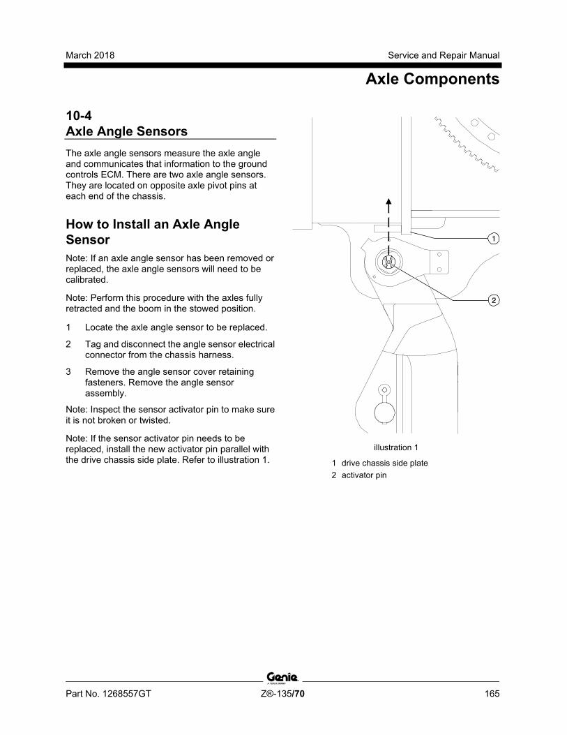
March 2018 Service and Repair Manual
Axle Components
Part No. 1268557GT Z®-135/70 165
10-4 Axle Angle Sensors The axle angle sensors measure the axle angle and communicates that information to the ground controls ECM. There are two axle angle sensors. They are located on opposite axle pivot pins at each end of the chassis.
How to Install an Axle Angle Sensor Note: If an axle angle sensor has been removed or replaced, the axle angle sensors will need to be calibrated.
Note: Perform this procedure with the axles fully retracted and the boom in the stowed position.
1 Locate the axle angle sensor to be replaced.
2 Tag and disconnect the angle sensor electrical connector from the chassis harness.
3 Remove the angle sensor cover retaining fasteners. Remove the angle sensor assembly.
Note: Inspect the sensor activator pin to make sure it is not broken or twisted.
Note: If the sensor activator pin needs to be replaced, install the new activator pin parallel with the drive chassis side plate. Refer to illustration 1.
illustration 1
1 drive chassis side plate 2 activator pin
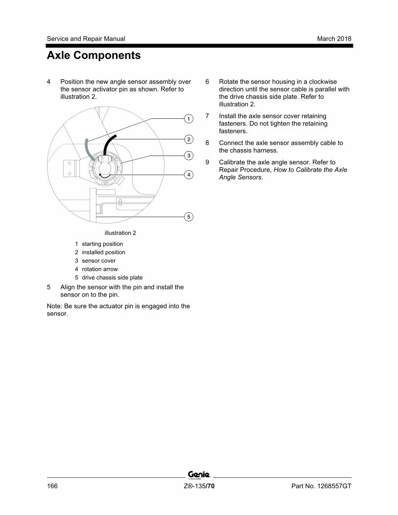
Service and Repair Manual March 2018
Axle Components
166 Z®-135/70 Part No. 1268557GT
4 Position the new angle sensor assembly over the sensor activator pin as shown. Refer to illustration 2.
illustration 2
1 starting position 2 installed position 3 sensor cover 4 rotation arrow 5 drive chassis side plate
5 Align the sensor with the pin and install the sensor on to the pin.
Note: Be sure the actuator pin is engaged into the sensor.
6 Rotate the sensor housing in a clockwise direction until the sensor cable is parallel with the drive chassis side plate. Refer to illustration 2.
7 Install the axle sensor cover retaining fasteners. Do not tighten the retaining fasteners.
8 Connect the axle sensor assembly cable to the chassis harness.
9 Calibrate the axle angle sensor. Refer to Repair Procedure, How to Calibrate the Axle Angle Sensors.
March 2018 Service and Repair Manual
Axle Components
Part No. 1268557GT Z®-135/70 167
How to C alibr ate the Axle Angl e Sensors
How to Calibrate the Axle Angle Sensors Note: Use the following chart to identify the description of each LCD screen control button used in this procedure.
Plus Minus Previous Enter
Note: If an axle angle sensor has been removed or replaced, the axle angle sensors will need to be calibrated.
Note: Perform this procedure with the axles fully retracted and the boom in the stowed position.
Note: Two people will be required to perform this procedure.
1 Turn the key switch to platform controls and pull out the red Emergency Stop button to the on position at both ground and platform controls.
2 Loosen the axle angle sensor cover retaining fasteners. Do not remove the fasteners or the sensor cover.
3 Using a voltmeter set to DC voltage, probe the back of the electrical connector at pins 2 and 3.
Note: If available, WebGPI can also be used for this procedure.
4 Rotate the sensor cover clockwise or counterclockwise until the voltage reading is between 4.2 to 4.4V DC. Tighten the sensor cover retaining fasteners.
5 Repeat steps 2 through 4 for the other axle angle sensor if needed.
6 Push in the ground controls red Emergency Stop button to the off position.
7 Open the ground control box.
Before serial number 321:
8 Locate the 2 pin connector in the lower left hand area of the ground control box.
9 Remove the connector plug and insert a jumper wire between the two pins of the connector.
After serial number 320:
10 Locate the calibration toggle switch at the top of the ground control box. Activate calibration mode by moving the toggle switch in the left direction.
11 Temporarily install a control box door retaining fastener between the door and the box to prevent the control box door from moving the toggle switch while calibrating the machine.
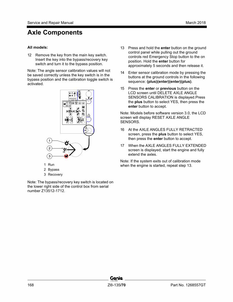
Service and Repair Manual March 2018
Axle Components
168 Z®-135/70 Part No. 1268557GT
All models:
12 Remove the key from the main key switch. Insert the key into the bypass/recovery key switch and turn it to the bypass position.
Note: The angle sensor calibration values will not be saved correctly unless the key switch is in the bypass position and the calibration toggle switch is activated.
1 Run 2 Bypass 3 Recovery
Note: The bypass/recovery key switch is located on the lower right side of the control box from serial number Z13512-1712.
13 Press and hold the enter button on the ground control panel while pulling out the ground controls red Emergency Stop button to the on position. Hold the enter button for approximately 5 seconds and then release it.
14 Enter sensor calibration mode by pressing the buttons at the ground controls in the following sequence: (plus)(enter)(enter)(plus).
15 Press the enter or previous button on the LCD screen until DELETE AXLE ANGLE SENSORS CALIBRATION is displayed.Press the plus button to select YES, then press the enter button to accept.
Note: Models before software version 3.0, the LCD screen will display RESET AXLE ANGLE SENSORS.
16 At the AXLE ANGLES FULLY RETRACTED screen, press the plus button to select YES, then press the enter button to accept.
17 When the AXLE ANGLES FULLY EXTENDED screen is displayed, start the engine and fully extend the axles.
Note: If the system exits out of calibration mode when the engine is started, repeat step 13.

March 2018 Service and Repair Manual
Axle Components
Part No. 1268557GT Z®-135/70 169
18 Press the plus button to select YES, then press the enter button to accept.
19 Press the enter or previous button on the LCD screen until EXIT is displayed.
20 Press the plus button to select YES, then press the enter button to accept.
21 Press and hold the engine start button for approximately 5 seconds to shut off the engine and to save the calibration settings.
Note: Do not turn the engine off with the key switch or red Emergency Stop button or all calibration points or values will not be saved.
22 Wait approximately 20 seconds and turn the machine off by pressing the red Emergency Stop button in.
Before serial number 321:
23 Remove the wire jumper from the 2 pin connector in the lower left hand area of the ground control box that was installed in step 8. Install the connector plug.
Tip-over hazard. Failure to remove the jumper wire will result in an unsafe configuration which will compromise machine stability. Operating the machine in this configuration will result in the machine tipping over, resulting in death or serious injury. The jumper wire must be removed before operating the machine.
24 Close the ground control box and install the door retaining fasteners.
After serial number 320:
25 Remove the fastener that was temporarily installed. Close the control box door and install the door retaining fasteners.
Note: When the control box door is closed, the calibration toggle switch is automatically activated to exit out of calibration mode.
All models:
26 Turn the key back to the run position and remove the key from the bypass/recovery key switch. Insert the key into the main key switch and turn it to ground controls.
Note: Be sure that the bypass/recovery key switch is in the run position before attempting to operate the machine.

Service and Repair Manual March 2018
170 Z®-135/70 Part No. 1268557GT
This page intentionally left blank.
March 2018 Service and Repair Manual
Fault Codes
Part No. 1268557GT Z®-135/70 171
Section 4 Faul t Codes
Observe and Obey: Troubleshooting and repair procedures shall
be completed by a person trained and qualified on the repair of this machine
Immediately tag and remove from service a damaged or malfunctioning machine.
Repair any machine damage or malfunction before operating the machine.
Unless otherwise specified, perform each procedure with the machine in the following configuration:
• Machine parked on a firm, level surface
• Key switch in the off position with the key removed
• The red Emergency Stop button in the off position at both the ground and platform controls
• Wheels chocked
• All external AC power supply disconnected from the machine
• Boom in the stowed position
• Turntable secured with the turntable rotation lock
• Welder disconnected from the machine (if equipped with the weld cable to platform option)
Before Troubleshooting: Read, understand and obey the safety rules
and operating instructions in the appropriate operator's manual on your machine.
Be sure that all necessary tools and test equipment are available and ready for use.
Read each appropriate fault code thoroughly. Attempting short cuts may produce hazardous conditions.
Be aware of the following hazards and follow generally accepted safe workshop practices.
Electrocution/burn hazard. Contact with electrically charged circuits could result in death or serious injury. Remove all rings, watches and other jewelry.
Note: Two persons will be required to safely perform some troubleshooting procedures.

Service and Repair Manual March 2018
Fault Codes
172 Z®-135/70 Part No. 1268557GT
Error Source Error Type Effects Recovery Actions Primary Ext/Ret Joystick Value at 5.0 V Limited Speed and Direction frozen at
zero and neutral, Alarm sounds Check for damaged wiring to the joystick. Check the connections to ensure the connector terminals have not backed out. Substitute a known good joystick. If necessary replace and recalibrate joystick.
Value Too High
Value Too Low
Value at 0 V
Not calibrated Joystick Speed and Direction frozen at zero and neutral
Calibrate Joystick
Just calibrated Initiate one second beep of audible warning device
Self-clearing (transient)
Primary Up/Down Joystick Value at 5.0 V Limited Speed and Direction frozen at zero and neutral, Alarm sounds
Check for damaged wiring to the joystick. Check the connections to ensure the connector terminals have not backed out. Substitute a known good joystick. If necessary replace and recalibrate joystick.
Value Too High
Value Too Low
Value at 0 V
Not calibrated Joystick Speed and Direction frozen at zero and neutral
Calibrate Joystick
Just calibrated Initiate one second beep of audible warning device
Self-clearing (transient)
Steer Joystick Value at 5.0 V Limited Speed and Direction frozen at zero and neutral, Alarm sounds
Check for damaged wiring to the joystick. Check the connections to ensure the connector terminals have not backed out. Substitute a known good joystick. If necessary replace and recalibrate joystick.
Value Too High
Value Too Low
Value at 0 V
Not calibrated Joystick Speed and Direction frozen at zero and neutral
Calibrate Joystick
Just calibrated Initiate one second beep of audible warning device
Self-clearing (transient)
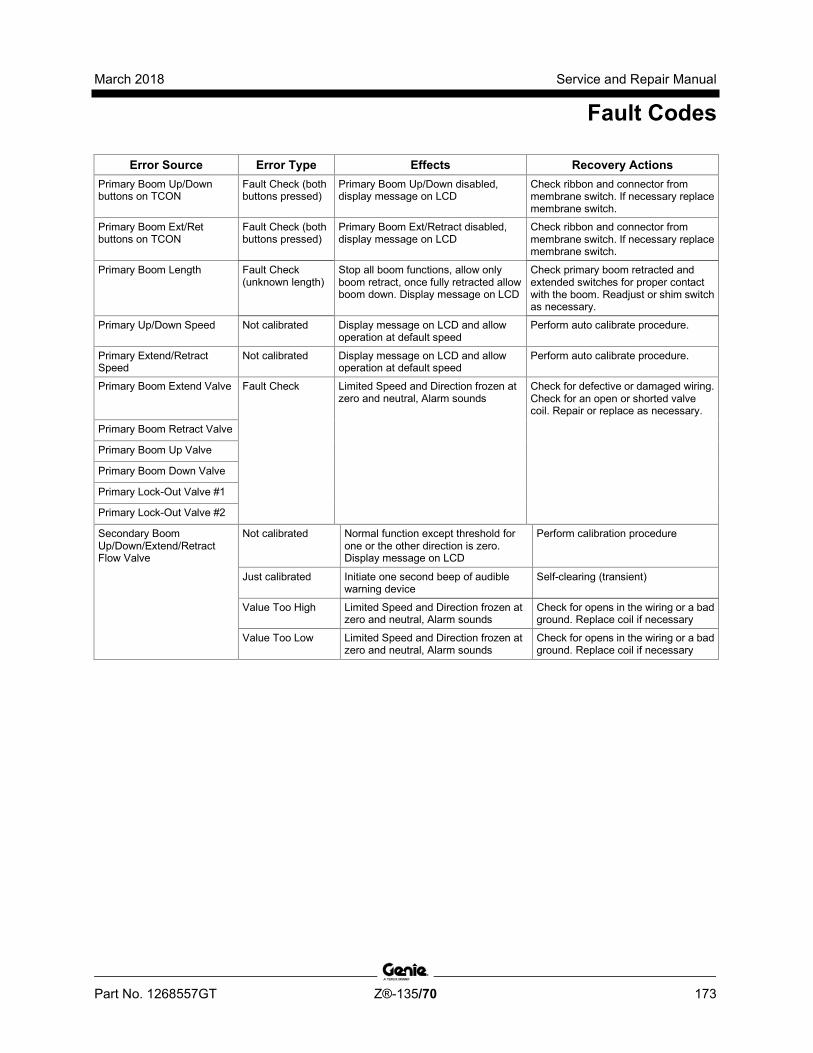
March 2018 Service and Repair Manual
Fault Codes
Part No. 1268557GT Z®-135/70 173
Error Source Error Type Effects Recovery Actions Primary Boom Up/Down buttons on TCON
Fault Check (both buttons pressed)
Primary Boom Up/Down disabled, display message on LCD
Check ribbon and connector from membrane switch. If necessary replace membrane switch.
Primary Boom Ext/Ret buttons on TCON
Fault Check (both buttons pressed)
Primary Boom Ext/Retract disabled, display message on LCD
Check ribbon and connector from membrane switch. If necessary replace membrane switch.
Primary Boom Length Fault Check (unknown length)
Stop all boom functions, allow only boom retract, once fully retracted allow boom down. Display message on LCD
Check primary boom retracted and extended switches for proper contact with the boom. Readjust or shim switch as necessary.
Primary Up/Down Speed Not calibrated Display message on LCD and allow operation at default speed
Perform auto calibrate procedure.
Primary Extend/Retract Speed
Not calibrated Display message on LCD and allow operation at default speed
Perform auto calibrate procedure.
Primary Boom Extend Valve Fault Check Limited Speed and Direction frozen at zero and neutral, Alarm sounds
Check for defective or damaged wiring. Check for an open or shorted valve coil. Repair or replace as necessary.
Primary Boom Retract Valve
Primary Boom Up Valve
Primary Boom Down Valve
Primary Lock-Out Valve #1
Primary Lock-Out Valve #2
Secondary Boom Up/Down/Extend/Retract Flow Valve
Not calibrated Normal function except threshold for one or the other direction is zero. Display message on LCD
Perform calibration procedure
Just calibrated Initiate one second beep of audible warning device
Self-clearing (transient)
Value Too High Limited Speed and Direction frozen at zero and neutral, Alarm sounds
Check for opens in the wiring or a bad ground. Replace coil if necessary
Value Too Low Limited Speed and Direction frozen at zero and neutral, Alarm sounds
Check for opens in the wiring or a bad ground. Replace coil if necessary
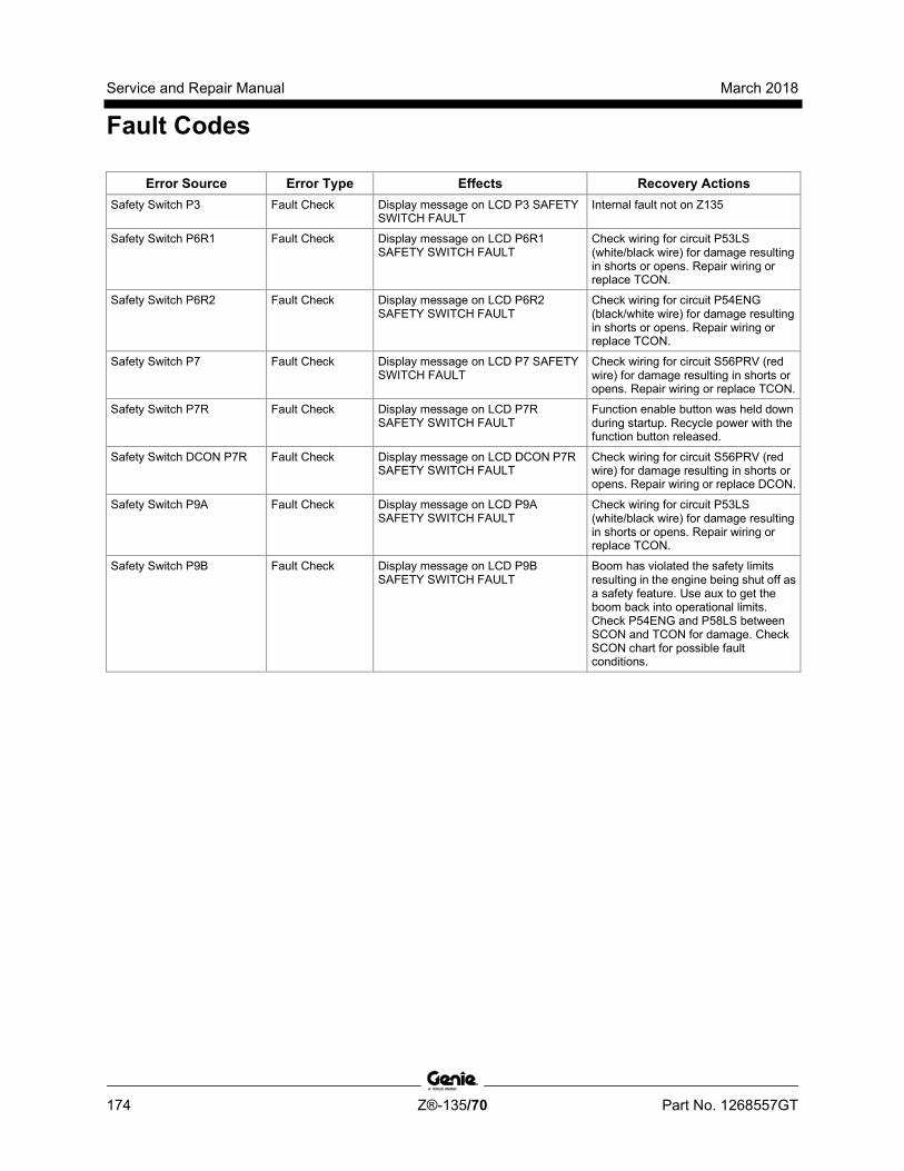
Service and Repair Manual March 2018
Fault Codes
174 Z®-135/70 Part No. 1268557GT
Error Source Error Type Effects Recovery Actions Safety Switch P3 Fault Check Display message on LCD P3 SAFETY
SWITCH FAULT Internal fault not on Z135
Safety Switch P6R1 Fault Check Display message on LCD P6R1 SAFETY SWITCH FAULT
Check wiring for circuit P53LS (white/black wire) for damage resulting in shorts or opens. Repair wiring or replace TCON.
Safety Switch P6R2 Fault Check Display message on LCD P6R2 SAFETY SWITCH FAULT
Check wiring for circuit P54ENG (black/white wire) for damage resulting in shorts or opens. Repair wiring or replace TCON.
Safety Switch P7 Fault Check Display message on LCD P7 SAFETY SWITCH FAULT
Check wiring for circuit S56PRV (red wire) for damage resulting in shorts or opens. Repair wiring or replace TCON.
Safety Switch P7R Fault Check Display message on LCD P7R SAFETY SWITCH FAULT
Function enable button was held down during startup. Recycle power with the function button released.
Safety Switch DCON P7R Fault Check Display message on LCD DCON P7R SAFETY SWITCH FAULT
Check wiring for circuit S56PRV (red wire) for damage resulting in shorts or opens. Repair wiring or replace DCON.
Safety Switch P9A Fault Check Display message on LCD P9A SAFETY SWITCH FAULT
Check wiring for circuit P53LS (white/black wire) for damage resulting in shorts or opens. Repair wiring or replace TCON.
Safety Switch P9B Fault Check Display message on LCD P9B SAFETY SWITCH FAULT
Boom has violated the safety limits resulting in the engine being shut off as a safety feature. Use aux to get the boom back into operational limits. Check P54ENG and P58LS between SCON and TCON for damage. Check SCON chart for possible fault conditions.

March 2018 Service and Repair Manual
Fault Codes
Part No. 1268557GT Z®-135/70 175
Error Source Error Type Effects Recovery Actions Safety Switch P10 Fault Check Display message on LCD P10
SAFETY SWITCH FAULT Recycle power
Safety Switch P11 Fault Check Display message on LCD P11 SAFETY SWITCH FAULT
Recycle power and check wiring on circuit S140ENL (orange/black) between SCON and TCON. Check SCON chart for possible faults.
Safety Switch P12 Fault Check Display message on LCD P12 SAFETY SWITCH FAULT
Recycle power
Safety Switch P14 Fault Check Display message on LCD P14 SAFETY SWITCH FAULT
Recycle power
Safety Switch P18 Fault Check Display message on LCD P18 SAFETY SWITCH FAULT
Recycle power
Safety Switch P22 Fault Check Display message on LCD P22 SAFETY SWITCH FAULT
Re-level platform. Check for wiring damage on circuit P56PRV (red/white).
Safety Switch P22R Fault Check Display message on LCD P22R SAFETY SWITCH FAULT
Re-level platform. Repair or replace PCON.
Safety Switch P30 Fault Check Display message on LCD P30 SAFETY SWITCH FAULT
Recycle power and check wiring on circuit S140ENL (orange/black) between SCON and TCON. Check SCON chart for possible faults.
Safety Switch P38 Fault Check Display message on LCD P38 SAFETY SWITCH FAULT
Recycle power and check wiring on circuit S137PLL (red/white) between SCON and TCON. Check SCON chart for possible faults.
Safety Switch P39 Fault Check Display message on LCD P39 SAFETY SWITCH FAULT
Recycle power and check wiring on circuit S139TRF (white/red) between SCON and TCON. Check SCON chart for possible faults.
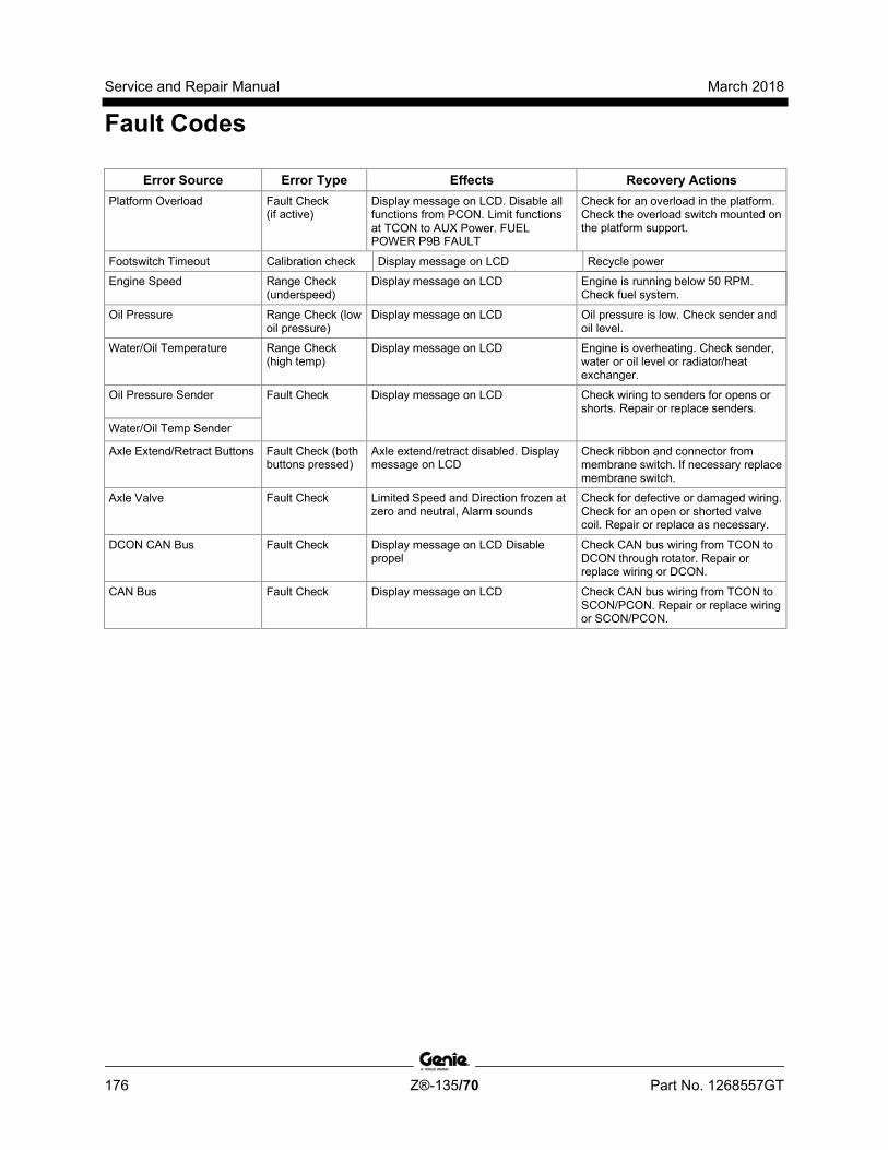
Service and Repair Manual March 2018
Fault Codes
176 Z®-135/70 Part No. 1268557GT
Error Source Error Type Effects Recovery Actions Platform Overload Fault Check
(if active) Display message on LCD. Disable all functions from PCON. Limit functions at TCON to AUX Power. FUEL POWER P9B FAULT
Check for an overload in the platform. Check the overload switch mounted on the platform support.
Footswitch Timeout Calibration check Display message on LCD Recycle power
Engine Speed Range Check (underspeed)
Display message on LCD Engine is running below 50 RPM. Check fuel system.
Oil Pressure Range Check (low oil pressure)
Display message on LCD Oil pressure is low. Check sender and oil level.
Water/Oil Temperature Range Check (high temp)
Display message on LCD Engine is overheating. Check sender, water or oil level or radiator/heat exchanger.
Oil Pressure Sender Fault Check Display message on LCD Check wiring to senders for opens or shorts. Repair or replace senders.
Water/Oil Temp Sender
Axle Extend/Retract Buttons Fault Check (both buttons pressed)
Axle extend/retract disabled. Display message on LCD
Check ribbon and connector from membrane switch. If necessary replace membrane switch.
Axle Valve Fault Check Limited Speed and Direction frozen at zero and neutral, Alarm sounds
Check for defective or damaged wiring. Check for an open or shorted valve coil. Repair or replace as necessary.
DCON CAN Bus Fault Check Display message on LCD Disable propel
Check CAN bus wiring from TCON to DCON through rotator. Repair or replace wiring or DCON.
CAN Bus Fault Check Display message on LCD Check CAN bus wiring from TCON to SCON/PCON. Repair or replace wiring or SCON/PCON.
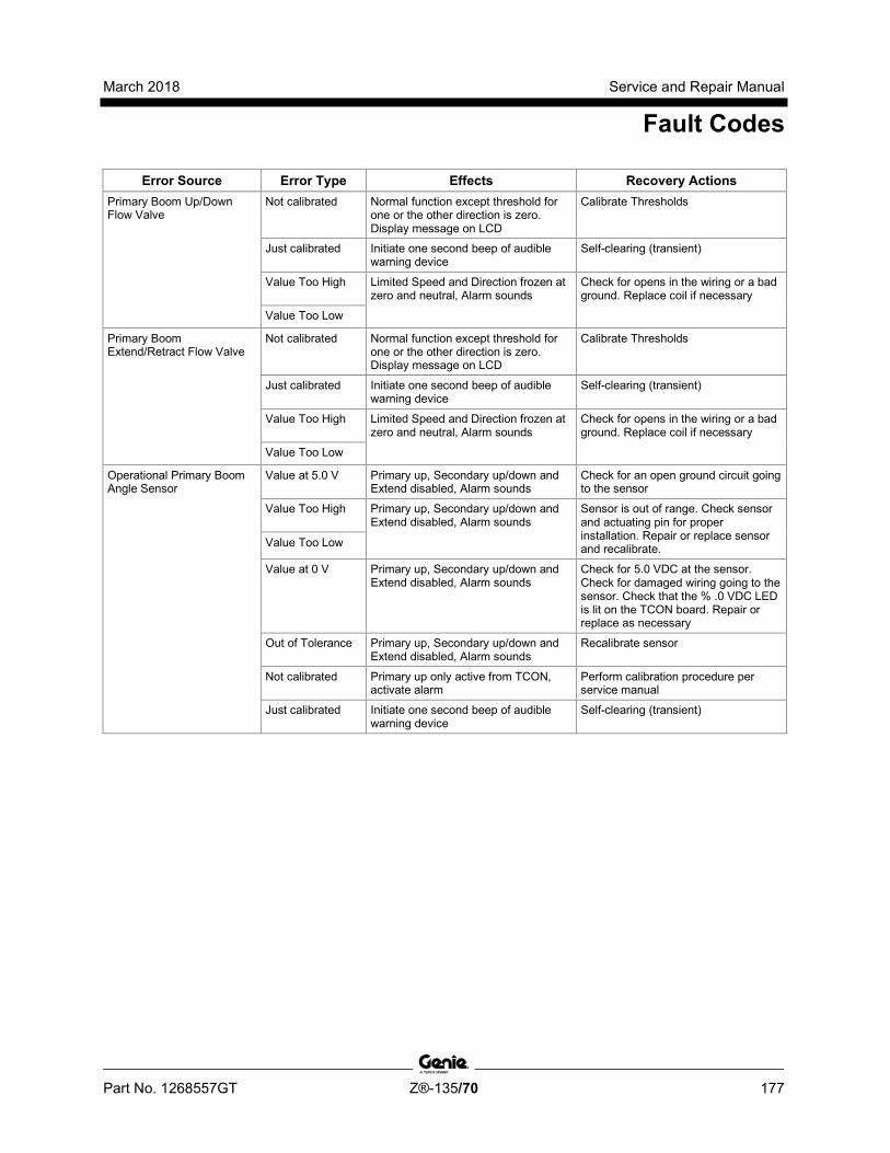
March 2018 Service and Repair Manual
Fault Codes
Part No. 1268557GT Z®-135/70 177
Error Source Error Type Effects Recovery Actions Primary Boom Up/Down Flow Valve
Not calibrated Normal function except threshold for one or the other direction is zero. Display message on LCD
Calibrate Thresholds
Just calibrated Initiate one second beep of audible warning device
Self-clearing (transient)
Value Too High Limited Speed and Direction frozen at zero and neutral, Alarm sounds
Check for opens in the wiring or a bad ground. Replace coil if necessary
Value Too Low
Primary Boom Extend/Retract Flow Valve
Not calibrated Normal function except threshold for one or the other direction is zero. Display message on LCD
Calibrate Thresholds
Just calibrated Initiate one second beep of audible warning device
Self-clearing (transient)
Value Too High Limited Speed and Direction frozen at zero and neutral, Alarm sounds
Check for opens in the wiring or a bad ground. Replace coil if necessary
Value Too Low
Operational Primary Boom Angle Sensor
Value at 5.0 V Primary up, Secondary up/down and Extend disabled, Alarm sounds
Check for an open ground circuit going to the sensor
Value Too High Primary up, Secondary up/down and Extend disabled, Alarm sounds
Sensor is out of range. Check sensor and actuating pin for proper installation. Repair or replace sensor and recalibrate. Value Too Low
Value at 0 V Primary up, Secondary up/down and Extend disabled, Alarm sounds
Check for 5.0 VDC at the sensor. Check for damaged wiring going to the sensor. Check that the % .0 VDC LED is lit on the TCON board. Repair or replace as necessary
Out of Tolerance Primary up, Secondary up/down and Extend disabled, Alarm sounds
Recalibrate sensor
Not calibrated Primary up only active from TCON, activate alarm
Perform calibration procedure per service manual
Just calibrated Initiate one second beep of audible warning device
Self-clearing (transient)

Service and Repair Manual March 2018
Fault Codes
178 Z®-135/70 Part No. 1268557GT
Error Source Error Type Effects Recovery Actions Safety Primary Boom Angle Sensor
Value at 5.0 V Primary up, Secondary up/down and Extend disabled, Alarm sounds
Check for an open ground circuit going to the sensor
Value Too High Primary up, Secondary up/down and Extend disabled, Alarm sounds
Sensor is out of range. Check sensor and actuating pin for proper installation. Repair or replace sensor and recalibrate. Value Too Low
Value at 0 V Primary up, Secondary up/down and Extend disabled, Alarm sounds
Check for 5.0 VDC at the sensor. Check for damaged wiring going to the sensor. Check that the % .0 VDC LED is lit on the TCON board. Repair or replace as necessary
Out of Tolerance Primary up, Secondary up/down and Extend disabled, Alarm sounds
Recalibrate sensor
Not calibrated Primary up only active from TCON, activate alarm
Perform calibration procedure per service manual
Just calibrated Initiate one second beep of audible warning device
Self-clearing (transient)
Secondary Boom Joystick Value at 5.0 V Primary up, Secondary up/down and Extend disabled, Alarm sounds
Check for damaged wiring to the joystick. Check the connections to ensure the connector terminals have not backed out. Substitute a known good joystick. If necessary replace and recalibrate joystick.
Value Too High
Value Too Low
Value at 0 V
Not calibrated Joystick Speed and Direction frozen at zero and neutral
Just calibrated Initiate one second beep of audible warning device
Self-clearing (transient)
Secondary Boom Up/Extend/Down/Retract Switches on TCON
Fault Check (both buttons pressed)
Secondary boom Up/Ext/Down/Retract disabled Display message on LCD
Check ribbon and connector from membrane switch. If necessary replace membrane switch.
Secondary Boom Up/Down Speed
Not calibrated Display message on LCD and allow operation at default speed
See service manual on how to perform this procedure.

March 2018 Service and Repair Manual
Fault Codes
Part No. 1268557GT Z®-135/70 179
Error Source Error Type Effects Recovery Actions Secondary Boom Extend Valve
Fault Check Limited Speed and Direction frozen at zero and neutral, Alarm sounds
Check for defective or damaged wiring. Check for an open or shorted valve coil. Repair or replace as necessary.
Secondary Boom Retract Valve
Fault Check Limited Speed and Direction frozen at zero and neutral, Alarm sounds
Check for defective or damaged wiring. Check for an open or shorted valve coil. Repair or replace as necessary.
Secondary Boom Up Valve
Fault Check Limited Speed and Direction frozen at zero and neutral, Alarm sounds
Check for defective or damaged wiring. Check for an open or shorted valve coil. Repair or replace as necessary.
Secondary Boom Down Valve
Fault Check Limited Speed and Direction frozen at zero and neutral, Alarm sounds
Check for defective or damaged wiring. Check for an open or shorted valve coil. Repair or replace as necessary.
Secondary Boom Extend Sequence Valve
Fault Check Limited Speed and Direction frozen at zero and neutral, Alarm sounds
Check for defective or damaged wiring. Check for an open or shorted valve coil. Repair or replace as necessary.
Secondary Boom Down Sequence Valve
Fault Check Limited Speed and Direction frozen at zero and neutral, Alarm sounds
Check for defective or damaged wiring. Check for an open or shorted valve coil. Repair or replace as necessary.
Operational Secondary Boom Angle Sensor
Value at 5.0 V Primary up, Secondary up/down and Extend disabled, Alarm sounds
Check for an open ground circuit going to the sensor
Value Too High Primary up, Secondary up/down and Extend disabled, Alarm sounds
Sensor is out of range. Check sensor and actuating pin for proper installation. Repair or replace sensor and recalibrate. Value Too Low
Value at 0 V Primary up, Secondary up/down and Extend disabled, Alarm sounds
Check for 5.0 VDC at the sensor. Check for damaged wiring going to the sensor. Check that the % .0 VDC LED is lit on the TCON board. Repair or replace as necessary
Out of Tolerance Primary up, Secondary up/down and Extend disabled, Alarm sounds
Recalibrate sensor
Not calibrated Secondary up only active from TCON, activate alarm
Perform calibration procedure per service manual
Just calibrated Initiate one second beep of audible warning device
Self-clearing (transient)
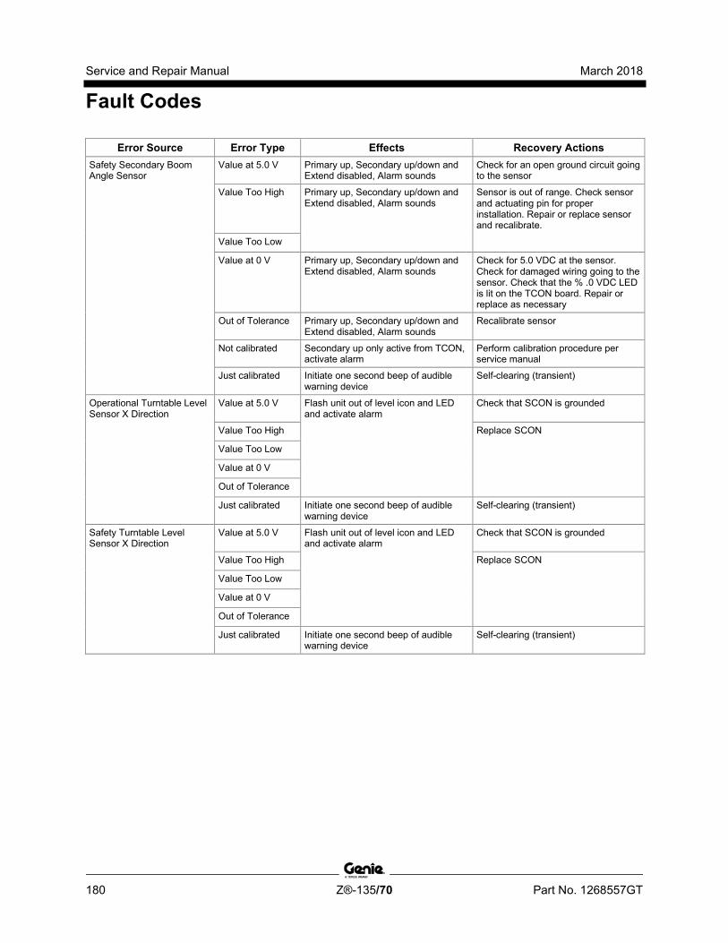
Service and Repair Manual March 2018
Fault Codes
180 Z®-135/70 Part No. 1268557GT
Error Source Error Type Effects Recovery Actions Safety Secondary Boom Angle Sensor
Value at 5.0 V Primary up, Secondary up/down and Extend disabled, Alarm sounds
Check for an open ground circuit going to the sensor
Value Too High Primary up, Secondary up/down and Extend disabled, Alarm sounds
Sensor is out of range. Check sensor and actuating pin for proper installation. Repair or replace sensor and recalibrate.
Value Too Low
Value at 0 V Primary up, Secondary up/down and Extend disabled, Alarm sounds
Check for 5.0 VDC at the sensor. Check for damaged wiring going to the sensor. Check that the % .0 VDC LED is lit on the TCON board. Repair or replace as necessary
Out of Tolerance Primary up, Secondary up/down and Extend disabled, Alarm sounds
Recalibrate sensor
Not calibrated Secondary up only active from TCON, activate alarm
Perform calibration procedure per service manual
Just calibrated Initiate one second beep of audible warning device
Self-clearing (transient)
Operational Turntable Level Sensor X Direction
Value at 5.0 V Flash unit out of level icon and LED and activate alarm
Check that SCON is grounded
Value Too High Replace SCON
Value Too Low
Value at 0 V
Out of Tolerance
Just calibrated Initiate one second beep of audible warning device
Self-clearing (transient)
Safety Turntable Level Sensor X Direction
Value at 5.0 V Flash unit out of level icon and LED and activate alarm
Check that SCON is grounded
Value Too High Replace SCON
Value Too Low
Value at 0 V
Out of Tolerance
Just calibrated Initiate one second beep of audible warning device
Self-clearing (transient)
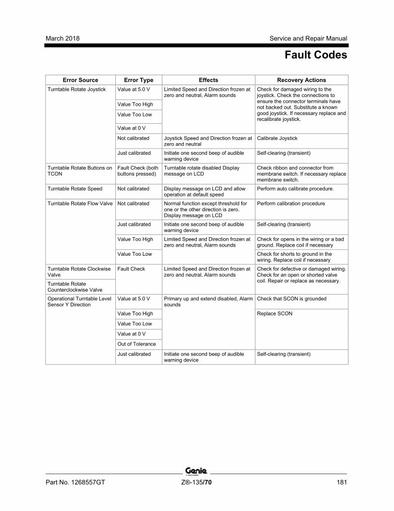
March 2018 Service and Repair Manual
Fault Codes
Part No. 1268557GT Z®-135/70 181
Error Source Error Type Effects Recovery Actions Turntable Rotate Joystick Value at 5.0 V Limited Speed and Direction frozen at
zero and neutral, Alarm sounds Check for damaged wiring to the joystick. Check the connections to ensure the connector terminals have not backed out. Substitute a known good joystick. If necessary replace and recalibrate joystick.
Value Too High
Value Too Low
Value at 0 V
Not calibrated Joystick Speed and Direction frozen at zero and neutral
Calibrate Joystick
Just calibrated Initiate one second beep of audible warning device
Self-clearing (transient)
Turntable Rotate Buttons on TCON
Fault Check (both buttons pressed)
Turntable rotate disabled Display message on LCD
Check ribbon and connector from membrane switch. If necessary replace membrane switch.
Turntable Rotate Speed Not calibrated Display message on LCD and allow operation at default speed
Perform auto calibrate procedure.
Turntable Rotate Flow Valve Not calibrated Normal function except threshold for one or the other direction is zero. Display message on LCD
Perform calibration procedure
Just calibrated Initiate one second beep of audible warning device
Self-clearing (transient)
Value Too High Limited Speed and Direction frozen at zero and neutral, Alarm sounds
Check for opens in the wiring or a bad ground. Replace coil if necessary
Value Too Low Check for shorts to ground in the wiring. Replace coil if necessary
Turntable Rotate Clockwise Valve
Fault Check Limited Speed and Direction frozen at zero and neutral, Alarm sounds
Check for defective or damaged wiring. Check for an open or shorted valve coil. Repair or replace as necessary. Turntable Rotate
Counterclockwise Valve
Operational Turntable Level Sensor Y Direction
Value at 5.0 V Primary up and extend disabled, Alarm sounds
Check that SCON is grounded
Value Too High Replace SCON
Value Too Low
Value at 0 V
Out of Tolerance
Just calibrated Initiate one second beep of audible warning device
Self-clearing (transient)
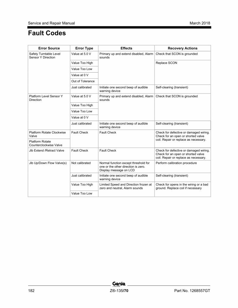
Service and Repair Manual March 2018
Fault Codes
182 Z®-135/70 Part No. 1268557GT
Error Source Error Type Effects Recovery Actions Safety Turntable Level Sensor Y Direction
Value at 5.0 V Primary up and extend disabled, Alarm sounds
Check that SCON is grounded
Value Too High Replace SCON
Value Too Low
Value at 0 V
Out of Tolerance
Just calibrated Initiate one second beep of audible warning device
Self-clearing (transient)
Platform Level Sensor Y Direction
Value at 5.0 V Primary up and extend disabled, Alarm sounds
Check that SCON is grounded
Value Too High
Value Too Low
Value at 0 V
Just calibrated Initiate one second beep of audible warning device
Self-clearing (transient)
Platform Rotate Clockwise Valve
Fault Check Fault Check Check for defective or damaged wiring. Check for an open or shorted valve coil. Repair or replace as necessary. Platform Rotate
Counterclockwise Valve
Jib Extend /Retract Valve Fault Check Fault Check Check for defective or damaged wiring. Check for an open or shorted valve coil. Repair or replace as necessary.
Jib Up/Down Flow Valve(s) Not calibrated Normal function except threshold for one or the other direction is zero. Display message on LCD
Perform calibration procedure
Just calibrated Initiate one second beep of audible warning device
Self-clearing (transient)
Value Too High Limited Speed and Direction frozen at zero and neutral, Alarm sounds
Check for opens in the wiring or a bad ground. Replace coil if necessary
Value Too Low
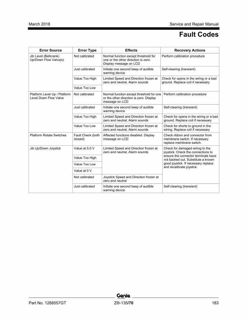
March 2018 Service and Repair Manual
Fault Codes
Part No. 1268557GT Z®-135/70 183
Error Source Error Type Effects Recovery Actions Jib Level (Bellcrank) Up/Down Flow Valve(s)
Not calibrated Normal function except threshold for one or the other direction is zero. Display message on LCD
Perform calibration procedure
Just calibrated Initiate one second beep of audible warning device
Self-clearing (transient)
Value Too High Limited Speed and Direction frozen at zero and neutral, Alarm sounds
Check for opens in the wiring or a bad ground. Replace coil if necessary
Value Too Low
Platform Level Up / Platform Level Down Flow Valve
Not calibrated Normal function except threshold for one or the other direction is zero. Display message on LCD
Perform calibration procedure
Just calibrated Initiate one second beep of audible warning device
Self-clearing (transient)
Value Too High Limited Speed and Direction frozen at zero and neutral, Alarm sounds
Check for opens in the wiring or a bad ground. Replace coil if necessary
Value Too Low Limited Speed and Direction frozen at zero and neutral, Alarm sounds
Check for shorts to ground in the wiring. Replace coil if necessary
Platform Rotate Switches Fault Check (both closed)
Affected functions disabled. Display message on LCD
Check ribbon and connector from membrane switch. If necessary replace membrane switch.
Jib Up/Down Joystick Value at 5.0 V Limited Speed and Direction frozen at zero and neutral, Alarm sounds
Check for damaged wiring to the joystick. Check the connections to ensure the connector terminals have not backed out. Substitute a known good joystick. If necessary replace and recalibrate joystick.
Value Too High
Value Too Low
Value at 0 V
Not calibrated Joystick Speed and Direction frozen at zero and neutral
Just calibrated Initiate one second beep of audible warning device
Self-clearing (transient)

Service and Repair Manual March 2018
Fault Codes
184 Z®-135/70 Part No. 1268557GT
Error Source Error Type Effects Recovery Actions Jib Extend/Retract Joystick Value at 5.0 V Limited Speed and Direction frozen at
zero and neutral, Alarm sounds Check for damaged wiring to the joystick. Check the connections to ensure the connector terminals have not backed out. Substitute a known good joystick. If necessary replace and recalibrate joystick.
Value Too High
Value Too Low
Value at 0 V
Not calibrated Joystick Speed and Direction frozen at zero and neutral
Calibrate Joystick
Just calibrated Initiate one second beep of audible warning device
Self-clearing (transient)
Platform Rotate Joystick Value at 5.0 V Limited Speed and Direction frozen at zero and neutral, Alarm sounds
Power up controller with problem corrected.
Value Too High
Value Too Low
Value at 0 V
Not calibrated Joystick Speed and Direction frozen at zero and neutral
Calibrate Joystick
Just calibrated Initiate one second beep of audible warning device
Self-clearing (transient)
Front Axle Angle Sensor Value at 5.0 V Primary up, Secondary up/down and Extend disabled, Alarm sounds
Check for an open ground circuit going to the sensor
Value Too High Primary up, Secondary up/down and Extend disabled, Alarm sounds
Sensor is out of range. Check sensor and actuating pin for proper installation. Repair or replace sensor and recalibrate. Value Too Low
Value at 0 V Primary up, Secondary up/down and Extend disabled, Alarm sounds
Check for 5.0 VDC at the sensor. Check for damaged wiring going to the sensor. Check that the % .0 VDC LED is lit on the TCON board. Repair or replace as necessary
Out of Tolerance Primary up, Secondary up/down and Extend disabled, Alarm sounds
Recalibrate sensor
Not calibrated Primary up only active from TCON, activate alarm
Perform calibration procedure per service manual
Just calibrated Initiate one second beep of audible warning device
Self-clearing (transient)

March 2018 Service and Repair Manual
Fault Codes
Part No. 1268557GT Z®-135/70 185
Error Source Error Type Effects Recovery Actions Rear Axle Angle Sensor Value at 5.0 V Primary up, Secondary up/down and
Extend disabled, Alarm sounds Check for an open ground circuit going to the sensor
Value Too High Primary up, Secondary up/down and Extend disabled, Alarm sounds
Sensor is out of range. Check sensor and actuating pin for proper installation. Repair or replace sensor and recalibrate. Value Too Low
Value at 0 V Primary up, Secondary up/down and Extend disabled, Alarm sounds
Check for 5.0 VDC at the sensor. Check for damaged wiring going to the sensor. Check that the % .0 VDC LED is lit on the TCON board. Repair or replace as necessary
Out of Tolerance Primary up, Secondary up/down and Extend disabled, Alarm sounds
Recalibrate sensor
Not calibrated Primary up only active from TCON, activate alarm
Perform calibration procedure per service manual
Just calibrated Initiate one second beep of audible warning device
Self-clearing (transient)
Propel Joystick Value at 5.0 V Limited Speed and Direction frozen at zero and neutral, Alarm sounds
Check for damaged wiring to the joystick. Check the connections to ensure the connector terminals have not backed out. Substitute a known good joystick. If necessary replace and recalibrate joystick.
Value Too High
Value Too Low
Value at 0 V
Not calibrated Joystick Speed and Direction frozen at zero and neutral
Calibrate Thresholds
Just calibrated Initiate one second beep of audible warning device
Self-clearing (transient)
Propel Valves Forward/Reverse
Not calibrated Joystick Speed and Direction frozen at zero and neutral
Calibrate Thresholds
Propel EDC Forward/Reverse
Just calibrated Initiate one second beep of audible warning device
Self-clearing (transient)
Value Too High Limited Speed and Direction frozen at zero and neutral, Alarm sounds
Check for opens in the wiring or a bad ground. Replace coil if necessary
Value Too Low Check for shorts to ground in the wiring. Replace coil if necessary
Motor Valve Speed Fault Check Limited Speed and Direction frozen at zero and neutral, Alarm sounds
Check for defective or damaged wiring. Check for an open or shorted valve coil. Repair or replace as necessary. Brake Valve
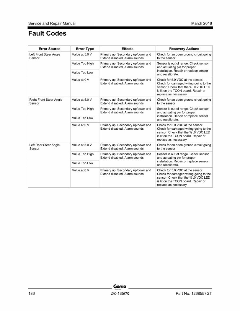
Service and Repair Manual March 2018
Fault Codes
186 Z®-135/70 Part No. 1268557GT
Error Source Error Type Effects Recovery Actions Left Front Steer Angle Sensor
Value at 5.0 V Primary up, Secondary up/down and Extend disabled, Alarm sounds
Check for an open ground circuit going to the sensor
Value Too High Primary up, Secondary up/down and Extend disabled, Alarm sounds
Sensor is out of range. Check sensor and actuating pin for proper installation. Repair or replace sensor and recalibrate. Value Too Low
Value at 0 V Primary up, Secondary up/down and Extend disabled, Alarm sounds
Check for 5.0 VDC at the sensor. Check for damaged wiring going to the sensor. Check that the % .0 VDC LED is lit on the TCON board. Repair or replace as necessary
Right Front Steer Angle Sensor
Value at 5.0 V Primary up, Secondary up/down and Extend disabled, Alarm sounds
Check for an open ground circuit going to the sensor
Value Too High Primary up, Secondary up/down and Extend disabled, Alarm sounds
Sensor is out of range. Check sensor and actuating pin for proper installation. Repair or replace sensor and recalibrate. Value Too Low
Value at 0 V Primary up, Secondary up/down and Extend disabled, Alarm sounds
Check for 5.0 VDC at the sensor. Check for damaged wiring going to the sensor. Check that the % .0 VDC LED is lit on the TCON board. Repair or replace as necessary
Left Rear Steer Angle Sensor
Value at 5.0 V Primary up, Secondary up/down and Extend disabled, Alarm sounds
Check for an open ground circuit going to the sensor
Value Too High Primary up, Secondary up/down and Extend disabled, Alarm sounds
Sensor is out of range. Check sensor and actuating pin for proper installation. Repair or replace sensor and recalibrate. Value Too Low
Value at 0 V Primary up, Secondary up/down and Extend disabled, Alarm sounds
Check for 5.0 VDC at the sensor. Check for damaged wiring going to the sensor. Check that the % .0 VDC LED is lit on the TCON board. Repair or replace as necessary

March 2018 Service and Repair Manual
Fault Codes
Part No. 1268557GT Z®-135/70 187
Error Source Error Type Effects Recovery Actions Right Rear Steer Angle Sensor
Value at 5.0 V Primary up, Secondary up/down and Extend disabled, Alarm sounds
Check for an open ground circuit going to the sensor
Value Too High Primary up, Secondary up/down and Extend disabled, Alarm sounds
Sensor is out of range. Check sensor and actuating pin for proper installation. Repair or replace sensor and recalibrate. Value Too Low
Value at 0 V Primary up, Secondary up/down and Extend disabled, Alarm sounds
Check for 5.0 VDC at the sensor. Check for damaged wiring going to the sensor. Check that the % .0 VDC LED is lit on the TCON board. Repair or replace as necessary
Steer Valves - LF, RF, LR, RR
Fault Check Limited Speed and Direction frozen at zero and neutral, Alarm sounds
Check for defective or damaged wiring. Check for an open or shorted valve coil. Repair or replace as necessary.
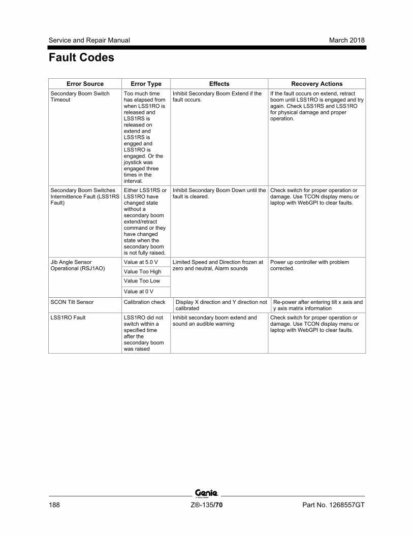
Service and Repair Manual March 2018
Fault Codes
188 Z®-135/70 Part No. 1268557GT
Error Source Error Type Effects Recovery Actions Secondary Boom Switch Timeout
Too much time has elapsed from when LSS1RO is released and LSS1RS is released on extend and LSS1RS is engged and LSS1RO is engaged. Or the joystick was engaged three times in the interval.
Inhibit Secondary Boom Extend if the fault occurs.
If the fault occurs on extend, retract boom until LSS1RO is engaged and try again. Check LSS1RS and LSS1RO for physical damage and proper operation.
Secondary Boom Switches Intermittence Fault (LSS1RS Fault)
Either LSS1RS or LSS1RO have changed state without a secondary boom extend/retract command or they have changed state when the secondary boom is not fully raised.
Inhibit Secondary Boom Down until the fault is cleared.
Check switch for proper operation or damage. Use TCON display menu or laptop with WebGPI to clear faults.
Jib Angle Sensor Operational (RSJ1AO)
Value at 5.0 V Limited Speed and Direction frozen at zero and neutral, Alarm sounds
Power up controller with problem corrected. Value Too High
Value Too Low
Value at 0 V
SCON Tilt Sensor Calibration check Display X direction and Y direction not calibrated
Re-power after entering tilt x axis and y axis matrix information
LSS1RO Fault LSS1RO did not switch within a specified time after the secondary boom was raised
Inhibit secondary boom extend and sound an audible warning
Check switch for proper operation or damage. Use TCON display menu or laptop with WebGPI to clear faults.
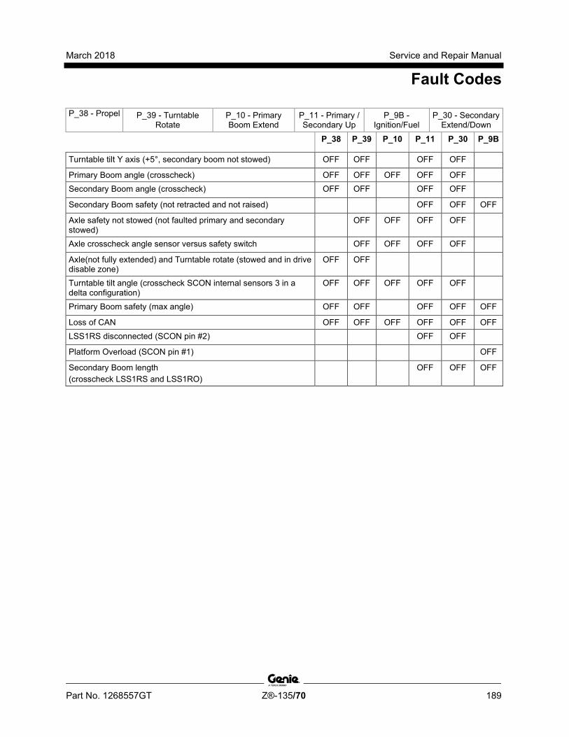
March 2018 Service and Repair Manual
Fault Codes
Part No. 1268557GT Z®-135/70 189
P_38 - Propel P_39 - Turntable Rotate
P_10 - Primary Boom Extend
P_11 - Primary / Secondary Up
P_9B - Ignition/Fuel
P_30 - Secondary Extend/Down
P_38 P_39 P_10 P_11 P_30 P_9B
Turntable tilt Y axis (+5°, secondary boom not stowed) OFF OFF OFF OFF
Primary Boom angle (crosscheck) OFF OFF OFF OFF OFF Secondary Boom angle (crosscheck) OFF OFF OFF OFF
Secondary Boom safety (not retracted and not raised) OFF OFF OFF
Axle safety not stowed (not faulted primary and secondary stowed)
OFF OFF OFF OFF
Axle crosscheck angle sensor versus safety switch OFF OFF OFF OFF
Axle(not fully extended) and Turntable rotate (stowed and in drive disable zone)
OFF OFF
Turntable tilt angle (crosscheck SCON internal sensors 3 in a delta configuration)
OFF OFF OFF OFF OFF
Primary Boom safety (max angle) OFF OFF OFF OFF OFF
Loss of CAN OFF OFF OFF OFF OFF OFF LSS1RS disconnected (SCON pin #2) OFF OFF
Platform Overload (SCON pin #1) OFF
Secondary Boom length (crosscheck LSS1RS and LSS1RO)
OFF OFF OFF

Service and Repair Manual March 2018
190 Z®-135/70 Part No. 1268557GT
This page intentionally left blank.
March 2018 Service and Repair Manual
Schematics
Part No. 1268557GT Z®-135/70 191
Section 5 Schem atics
Observe and Obey: Troubleshooting and repair procedures shall
be completed by a person trained and qualified on the repair of this machine
Immediately tag and remove from service a damaged or malfunctioning machine.
Repair any machine damage or malfunction before operating the machine.
Before Troubleshooting: Read, understand and obey the safety rules
and operating instructions in the appropriate operator's manual on your machine.
Be sure that all necessary tools and test equipment are available and ready for use.
About This Section There are two groups of schematics in this section.
Electrical Schematics
Electrocution/burn hazard. Contact with electrically charged circuits could result in death or serious injury. Remove all rings, watches and other jewelry.
Hydraulic Schematics
Bodily injury hazard. Spraying hydraulic oil can penetrate and burn skin. Loosen hydraulic connections very slowly to allow the oil pressure to dissipate gradually. Do not allow oil to squirt or spray.
Service and Repair Manual March 2018
Wire Circuit Legend
192 Z®-135/70 Part No. 1268557GT
Circuit numbering 1 Circuit numbers consist of three parts: the
circuit prefix, circuit number and circuit suffix. The circuit prefix indicates the type of circuit. The circuit number describes the function of the circuit. The circuit suffix provides an abbreviation for the number or may be used to further define the function of this portion of the circuit. It also may be used to indicate the final end of the circuit, i.e., LS or limit sw.
2 The circuit number may be used more than once in a circuit.
For Example:
C 74 PL – This is the circuit for the lockout valve #1. C stands for control, 74 is the number of the circuit for the primary #1 lock out valve. PL stands for Primary Lockout.
S 62 BST – This is the circuit that communicates to the onboard computers of the machine that the boom is fully stowed. S stands for safety, 62 is the number of the circuit for boom stowed and BST stands for Boom Stowed.
P 48 LP – P stands for power. 48 is the circuit number for work lamps and LP stands for Lamp.
R 48 LP – R stands for relay. In this case it is the wire that feeds the relay coil for the work lamp. All other numbers remain the same.
V61AXR – V stands for valve power. Number 61 stands for axle retracted circuit; AXR stands for Axle retracted.
R46HRN – R stands for Relay output, supplying power to the horn (HRN). Number 46 is the circuit number for the horn.
Circuit prefix C Control
D Data E Engine
G Gauges N Neutral
P Power R Relay Output
S Safety
V Valve

March 2018 Service and Repair Manual
Wire Circuit Legend
Part No. 1268557GT Z®-135/70 193
Suffix Definition ABV Auxiliary Boom Valve AF Alternator Field AFV Auxiliary Forward Valve AH Auxiliary Hydraulic Pump ANG Angle APV Auxiliary Platform Valve ARV Auxiliary Reverse Valve ASV Auxiliary Steer/Drive Valve AXE Axle Extend Valve AXO Axle Oscillate AXR Axle Retract Valve BAT Battery BEX Boom Extended BRK Brake BST Boom Stowed BV Bypass Valves CAL Calibrate CAN CAN Signal CAT CATS Module CNK Chain Break DCN Drive Chassis Controller DE Drive Enable DEL Drive Enable Left DER Drive Enable Right DTH Data High DTL Data Low EDC Electrical Displacement Control ENL Envelope Lockout ENV Envelope Light ERL Extend/Retract Lockout ESL Engine Status Lamp
Suffix Definition ESP Engine Speed Select FAP Axle Front Position FB Flashing Beacon FE Function Enable FL Fuel Select (gas/LP) FLR Filter Restricted FLT Filter Switch FP Fuel Pump FS Float Switch FSL Fuel Solenoid FTS Foot switch Signal FWD Forward GEN AC Generator GND Ground HG Hydraulic Generator HRN Horn HS High RPM IGN Ignition JBD Jib Bellcrank Down JBE Jib Extend JBR Jib Retract JBS Jib Sensor JBU Jib Bellcrank Up JD Jib Down JER Jib Extend/Retract Control JFC Jib Up/Down Flow Control JPL Propel Signal JPW Joystick 5V DC Power JRL Jib Rotate Left (CCW) JRR Jib Rotate Right (CW)
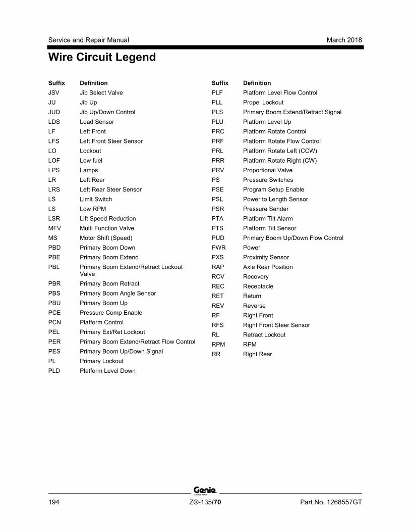
Service and Repair Manual March 2018
Wire Circuit Legend
194 Z®-135/70 Part No. 1268557GT
Suffix Definition JSV Jib Select Valve JU Jib Up JUD Jib Up/Down Control LDS Load Sensor LF Left Front LFS Left Front Steer Sensor LO Lockout LOF Low fuel LPS Lamps LR Left Rear LRS Left Rear Steer Sensor LS Limit Switch LS Low RPM LSR Lift Speed Reduction MFV Multi Function Valve MS Motor Shift (Speed) PBD Primary Boom Down PBE Primary Boom Extend PBL Primary Boom Extend/Retract Lockout
Valve PBR Primary Boom Retract PBS Primary Boom Angle Sensor PBU Primary Boom Up PCE Pressure Comp Enable PCN Platform Control PEL Primary Ext/Ret Lockout PER Primary Boom Extend/Retract Flow Control PES Primary Boom Up/Down Signal PL Primary Lockout PLD Platform Level Down
Suffix Definition PLF Platform Level Flow Control PLL Propel Lockout PLS Primary Boom Extend/Retract Signal PLU Platform Level Up PRC Platform Rotate Control PRF Platform Rotate Flow Control PRL Platform Rotate Left (CCW) PRR Platform Rotate Right (CW) PRV Proportional Valve PS Pressure Switches PSE Program Setup Enable PSL Power to Length Sensor PSR Pressure Sender PTA Platform Tilt Alarm PTS Platform Tilt Sensor PUD Primary Boom Up/Down Flow Control PWR Power PXS Proximity Sensor RAP Axle Rear Position RCV Recovery REC Receptacle RET Return REV Reverse RF Right Front RFS Right Front Steer Sensor RL Retract Lockout RPM RPM RR Right Rear

March 2018 Service and Repair Manual
Wire Circuit Legend
Part No. 1268557GT Z®-135/70 195
Suffix Definition RRS Right Rear Steer Sensor RS Rotary Sensor SA Start Aid (Glow Plug or choke) SB Secondary Boom SBD Sec Boom Down SBE Sec Boom Extend SBL Sec Boom Elevated SBR Sec Boom Retract SBS Sec Boom Angle Sensor SBU Sec Boom Up SCC Steering Valve (CCW) SCW Steering Valve (CW) SEN Sensor SER Sec Boom Extend/Retract Flow Control SHD CAN Shield SLD Secondary Boom Lockout Valve (riser
down) SLE Secondary Boom Lockout Valve (extend) SP Spare SS Speed Sensor STC Steer Control Signal
Suffix Definition STR Starter SUD Sec Boom Up/Down Flow Control TAX Tilt Alarm X axis TAY Tilt Alarm Y axis TCN Ground Control TCN Ground Control Panel TET Tether TRF Turntable Rotate Flow Control TRR Turntable Rotate Right (CW) TS Temp Switches TSR Temp Sender TSW Test Switch TTA Turntable Tilt Alarm TTS Turntable Tilt Sensor
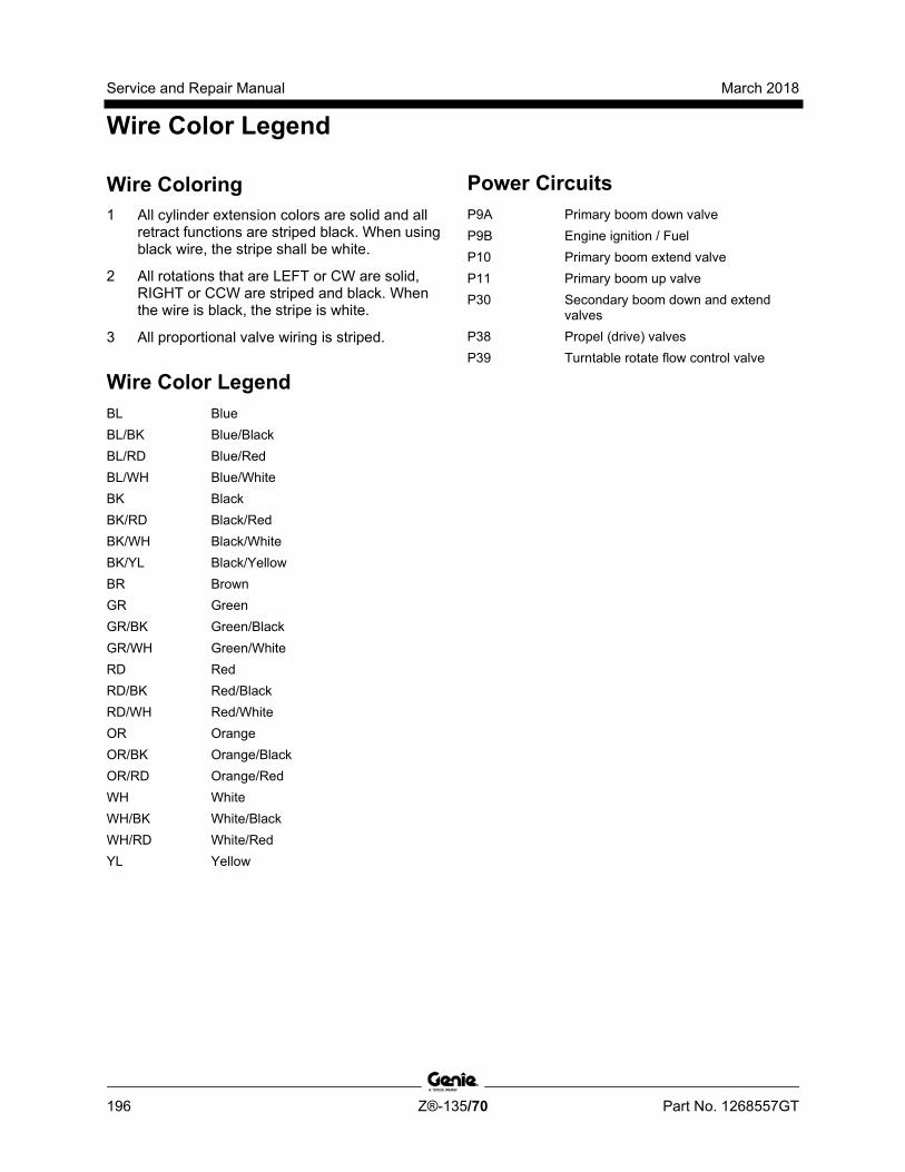
Service and Repair Manual March 2018
Wire Color Legend
196 Z®-135/70 Part No. 1268557GT
Wire Coloring 1 All cylinder extension colors are solid and all
retract functions are striped black. When using black wire, the stripe shall be white.
2 All rotations that are LEFT or CW are solid, RIGHT or CCW are striped and black. When the wire is black, the stripe is white.
3 All proportional valve wiring is striped.
Wire Color Legend BL Blue BL/BK Blue/Black BL/RD Blue/Red BL/WH Blue/White BK Black BK/RD Black/Red BK/WH Black/White BK/YL Black/Yellow BR Brown GR Green GR/BK Green/Black GR/WH Green/White RD Red RD/BK Red/Black RD/WH Red/White OR Orange OR/BK Orange/Black OR/RD Orange/Red WH White WH/BK White/Black WH/RD White/Red YL Yellow
Power Circuits P9A Primary boom down valve P9B Engine ignition / Fuel P10 Primary boom extend valve P11 Primary boom up valve P30 Secondary boom down and extend
valves P38 Propel (drive) valves P39 Turntable rotate flow control valve

March 2018 Service and Repair Manual
Wire Color Legend
Part No. 1268557GT Z®-135/70 197
Color Circuit # Primary Function RD 1 Primary boom up driver RD/BK 2 Primary boom down driver RD/WH 3 Primary boom up/down flow
control proportional valve driver WH 4 Turntable rotate left valve driver WH/BK 5 Turntable rotate right valve
driver WH/RD 6 Turntable rotate flow control
proportional valve driver BK 7 Primary boom extend BK/WH 8 Primary boom retract BK/RD 9 Primary boom Extend/Retract
proportional valve driver BL 10 Secondary boom up valve driver BL/BK 11 Secondary boom down valve
driver BL/WH 12 Secondary boom up/down flow
control proportional valve driver BL/RD 13 Drive enable OR 14 Platform level up valve OR/BK 15 Platform level down valve OR/RD 16 Platform up/down flow control
proportional valve driver GR 17 Platform rotate left valve driver GR/BK 18 Platform rotate right valve driver GR/WH 19 Jib select valve driver circuit RD 20 12V DC battery supply WH 21 12V DC ignition supply BK 22 Key switch power to platform WH 23 Power to platform RD 24 Power to warning senders WH/BK 25 Power to oil pressure sender
Color Circuit # Primary Function WH/RD 26 Power to temp sender RD 27 Auxiliary Power RD/BK 28 Platform level alarm RD/WH 29 Drive Motor shift (speed) WH 30 Forward/EDC-A WH/BK 31 Reverse/EDC-B WH/RD 32 Brake BK 33 Start BK/WH 34 Start Aid (glow plug or choke) BK/RD 35 High Engine speed select BL 36 Steer clockwise BL/BK 37 Steer counterclockwise BL/WH 38 Gasoline BL/RD 39 LPG OR 40 Limit switch signal stowed OR/BK 41 RPM signal OR/RD 42 Boom retracted signal GR 43 Jib Up GR/BK 44 Jib Down GR/WH 45 AC Generator WH 46 Horn WH/BK 47 Output Power Enable WH/RD 48 Work Lamp WH/BK 49 Motion Lamp BL 50 Auxiliary Boom BL/WH 51 Auxiliary Steer BL/RD 52 Auxiliary Platform WH/BK 53 Boom envelope safety valve
cutoff BK/WH 54 Power to safety interlock switches
(engine)
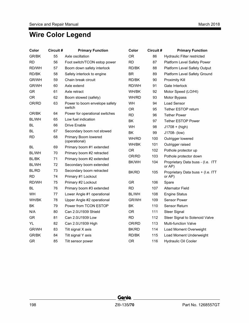
Service and Repair Manual March 2018
Wire Color Legend
198 Z®-135/70 Part No. 1268557GT
Color Circuit # Primary Function GR/BK 55 Axle oscillation RD 56 Foot switch/TCON estop power RD/WH 57 Boom down safety interlock RD/BK 58 Safety interlock to engine GR/WH 59 Chain break circuit GR/WH 60 Axle extend GR 61 Axle retract OR 62 Boom stowed (safety) OR/RD 63 Power to boom envelope safety
switch OR/BK 64 Power for operational switches BL/WH 65 Low fuel indication BL 66 Drive Enable BL 67 Secondary boom not stowed RD 68 Primary Boom lowered
(operational) BL 69 Primary boom #1 extended BL/WH 70 Primary boom #2 retracted BL/BK 71 Primary boom #2 extended BL/WH 72 Secondary boom extended BL/RD 73 Secondary boom retracted RD 74 Primary #1 Lockout RD/WH 75 Primary #2 Lockout BL 76 Primary boom #3 extended WH 77 Lower Angle #1 operational WH/BK 78 Upper Angle #2 operational BK 79 Power from TCON ESTOP N/A 80 Can 2.0/J1939 Shield GR 81 Can 2.0/J1939 Low YL 82 Can 2.0/J1939 High GR/WH 83 Tilt signal X axis GR/BK 84 Tilt signal Y axis GR 85 Tilt sensor power
Color Circuit # Primary Function OR 86 Hydraulic Filter restricted RD 87 Platform Level Safety Power RD/BK 88 Platform Level Safety Output BR 89 Platform Level Safety Ground RD/BK 90 Proximity Kill RD/WH 91 Gate Interlock WH/BK 92 Motor Speed (LO/HI) WH/RD 93 Motor Bypass WH 94 Load Sensor OR 95 Tether ESTOP return RD 96 Tether Power BK 97 Tether ESTOP Power WH 98 J1708 + (high) BK 99 J1708- (low) WH/RD 100 Outrigger lowered WH/BK 101 Outrigger raised OR 102 Pothole protector up OR/RD 103 Pothole protector down BK/WH 104 Proprietary Data buss - (I.e. ITT
or AP) BK/RD 105 Proprietary Data buss + (I.e. ITT
or AP) GR 106 Spare RD 107 Alternator Field BL/WH 108 Engine Status GR/WH 109 Sensor Power BK 110 Sensor Return OR 111 Steer Signal RD 112 Steer Signal to Solenoid Valve OR/RD 113 Multi-function Valve BK/RD 114 Load Moment Overweight RD/BK 115 Load Moment Underweight OR 116 Hydraulic Oil Cooler
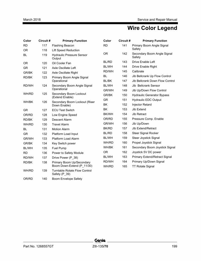
March 2018 Service and Repair Manual
Wire Color Legend
Part No. 1268557GT Z®-135/70 199
Color Circuit # Primary Function RD 117 Flashing Beacon OR 118 Lift Speed Reduction BL 119 Hydraulic Pressure Sensor
Output OR 120 Oil Cooler Fan GR 121 Axle Oscillate Left GR/BK 122 Axle Oscillate Right RD/BK 123 Primary Boom Angle Signal
Operational RD/WH 124 Secondary Boom Angle Signal
Operational WH/RD 125 Secondary Boom Lockout
(Extend Enable) WH/BK 126 Secondary Boom Lockout (Riser
Down Enable) GR 127 ECU Test Switch OR/RD 128 Low Engine Speed RD/BK 129 Descent Alarm WH/RD 130 Travel Alarm BL 131 Motion Alarm GR 132 Platform Load Input GR/WH 133 Platform Load Alarm GR/BK 134 Key Switch power BL/WH 135 Fuel Pump RD 136 Power to Safety Module RD/WH 137 Drive Power (P_38) RD/BK 138 Primary Boom Up/Secondary
Boom Down-Extend (P_11/30) WH/RD 139 Turntable Rotate Flow Control
Safety (P_39) OR/RD 140 Boom Envelope Safety
Color Circuit # Primary Function RD 141 Primary Boom Angle Signal
Safety OR 142 Secondary Boom Angle Signal
Safety BL/RD 143 Drive Enable Left BL/WH 144 Drive Enable Right RD/WH 145 Calibrate BL 146 Jib Bellcrank Up Flow Control BL/BK 147 Jib Bellcrank Down Flow Control BL/WH 148 Jib Bellcrank Sensor GR/WH 149 Jib Up/Down Flow Control GR/BK 150 Hydraulic Generator Bypass GR 151 Hydraulic EDC Output BK 152 Injector Retard BK 153 Jib Extend BK/WH 154 Jib Retract OR/RD 155 Pressure Comp. Enable GR/WH 156 Jib Up/Down BK/RD 157 Jib Extend/Retract BL/RD 158 Steer Signal Rocker BL/WH 159 Steer Joystick Signal WH/RD 160 Propel Joystick Signal WH/BK 161 Secondary Boom Joystick Signal OR 162 Joystick 5V DC power BL/WH 163 Primary Extend/Retract Signal RD/WH 164 Primary Up/Down Signal WH/RD 165 TT Rotate Signal

Service and Repair Manual March 2018
Wire Color Legend
200 Z®-135/70 Part No. 1268557GT
Color Circuit # Primary Function OR 166 Boom Length Signal Safety OR/BK 167 Boom Length Signal Operational BL/RD 168 Primary Boom Hydraulic Valve
Lockout GR 169 Envelope Active LED WH/RD 170 Load Sense Relay Source WH/BK 171 Load Sense Relay Sink BL 172 UP/DN Flow Control Ground BK 173 Ext/Ret Flow Control Ground WH 174 Key Switch Power, Ground
Position WH/BK 175 Load Sensor Signal Operational GR/WH 176 Secondary Extend/Retract FC BL/RD 177 Extend/Retract Lockout BK 178 Control Module Status Light GR 179 Drive Power Relay BK 180 Lift Power Relay OR 181 48 Volt Alternator field (or Battery) RD 182 24 Volt Battery BL 183 Envelope or Load Sense
Recovery WH 184 Program setup Enable WH 185 Encode A BL 186 Encode B BL 187 Bootstrap or Program Enable
Color Circuit # Primary Function GR 188 Safety cross check BK 189 Data Receive BK/WH 190 Data Transmit WH/RD 191 Multi-Function Pressure Relief WH/BK 192 Jib Rotate Left WH/RD 193 Jib Rotate Right WH/RD 194 Speed Select Input OR/RD 195 Electric Brake Source YL 196 2.5V Sensor Power WH 197 Hour Meter RD 198 +12V Sensor Power WH/RD 199 Thermal Switch BL 226 Telematics Remote Disable GR 227 Engine Control
CAN 2.0 / J1939 Low YL 228 Engine Control
CAN 2.0 / J1939 High BR N/A Ground or Return

March 2018 Service and Repair Manual
Limit Switches and Angle Sensors
Part No. 1268557GT Z®-135/70 201
Limit Switch Legend
1 RSP1AO 2 RSP1AS 3 LSP1RO 4 LST2O 5 LST1O 6 LST1S 7 LSS1RS 8 LSS1RO 9 RSS1AO 10 RSS1AS 11 LSP1EO 12 RSJ1AO 13 LSJ1RO
14 Plat Angle Sensor 15 PCON 16 SCON 17 RSRA1SO 18 LSRA1ES 19 RSLR1SO 20 RSRR1SO 21 DCON 22 RSRF1SO 23 RSLF1SO 24 LSFA1ES 25 RSFA1SO
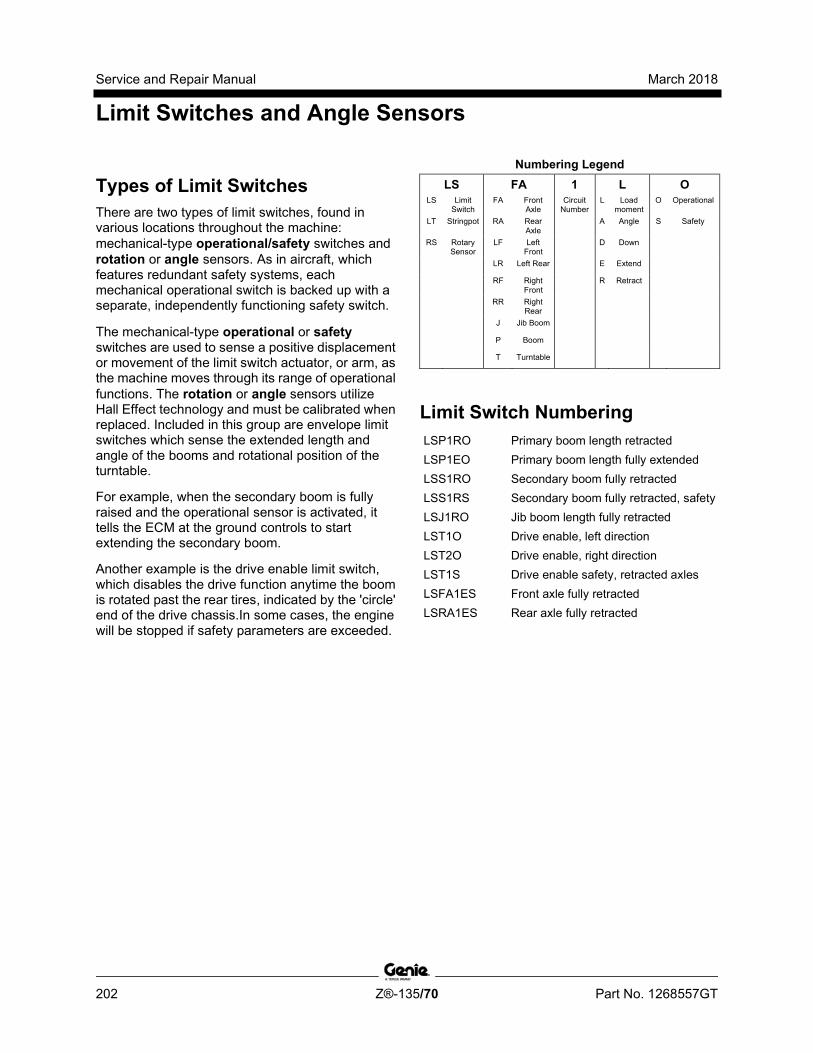
Service and Repair Manual March 2018
Limit Switches and Angle Sensors
202 Z®-135/70 Part No. 1268557GT
Types of Limit Switches There are two types of limit switches, found in various locations throughout the machine: mechanical-type operational/safety switches and rotation or angle sensors. As in aircraft, which features redundant safety systems, each mechanical operational switch is backed up with a separate, independently functioning safety switch.
The mechanical-type operational or safety switches are used to sense a positive displacement or movement of the limit switch actuator, or arm, as the machine moves through its range of operational functions. The rotation or angle sensors utilize Hall Effect technology and must be calibrated when replaced. Included in this group are envelope limit switches which sense the extended length and angle of the booms and rotational position of the turntable.
For example, when the secondary boom is fully raised and the operational sensor is activated, it tells the ECM at the ground controls to start extending the secondary boom.
Another example is the drive enable limit switch, which disables the drive function anytime the boom is rotated past the rear tires, indicated by the 'circle' end of the drive chassis.In some cases, the engine will be stopped if safety parameters are exceeded.
Numbering Legend LS FA 1 L O
LS Limit Switch
FA Front Axle
Circuit Number
L Load moment
O Operational
LT Stringpot RA Rear Axle
A Angle S Safety
RS Rotary Sensor
LF Left Front
D Down
LR Left Rear E Extend
RF Right Front
R Retract
RR Right Rear
J Jib Boom
P Boom
T Turntable
Limit Switch Numbering LSP1RO Primary boom length retracted LSP1EO Primary boom length fully extended LSS1RO Secondary boom fully retracted LSS1RS Secondary boom fully retracted, safety LSJ1RO Jib boom length fully retracted LST1O Drive enable, left direction LST2O Drive enable, right direction LST1S Drive enable safety, retracted axles LSFA1ES Front axle fully retracted LSRA1ES Rear axle fully retracted

March 2018 Service and Repair Manual
Limit Switches and Angle Sensors
Part No. 1268557GT Z®-135/70 203
Rotary Sensor Numbering RSP1AO Primary boom angle sensor RSP1AS Primary boom angle sensor, safety RSJ1AO Jib boom angle sensor RSS1AO Secondary boom angle sensor RSS1AS Secondary boom angle sensor, safety RSFA1O Front axle postioning sensor RSRA1O Rear axle positioning sensor RSLF1SO Left front wheel positioning sensor RSRF1SO Right front wheel positioning sensor RSLR1SO Left rear wheel positioning sensor RSRR1SO Right rear wheel positioning sensor
Limit Switch Functions Platform Angle Sensor: Measures the angle of the platform. The range of measurement is +/- 20 degrees. The safety cutout is set at +/- 10 degrees from gravity and will disable the primary and secondary boom up/down functions and the platform level up/down functions.
Jib Bell Crank Angle Sensor: Measures the angle of the jib bell crank. The range of measurement is + 60 / -70 degrees.
Safety Controller (SCON): Redundant dual axis tilt sensors measuring the X and Y tilt angles of the turntable. Also provides safety switch logic for function cut-off. Alarm sounds at ±4.5 degrees.
LSFA1ES: Limit switch, Front Axle #1 Extended Safety. Prevents boom functions with the axles retracted. Switch closes when axles are fully extended.
LSRA1ES: Limit switch, Rear Axle #1 Extended Safety. Prevents boom functions with the axles retracted. Switch closes when axles are fully extended.
LST1O: Limit switch, Turntable #1 Operational. Activates the drive enable zone when the turntable is rotated in the left direction.
LST2O: Limit switch, Turntable #2 Operational. Activates the drive enable zone when the turntable is rotated in the right direction.
LST1S: Limit switch, Turntable #1 Safety. Prevents the turntable from rotating out past either rear tire when axles are retracted.
LSS1RO: Limit switch, Secondary Boom #1 Retracted Operational. NOHC when secondary boom is fully retracted. Used to reduce turntable rotate speed when secondary boom is extended and to disable secondary boom down unitl fully retracted.
LSS1RS: Limit switch, Secondary Boom #1 Retract Safety Switch. Backup switch for LSS1RO. Used to cut circuits P9B, P_11 and P_30.
LSJ1RO: Limit Switch, Jib Boom #1 Retract Operational. Switch is held closed when the jib boom fully retracted. Used to limit turntable rotate speed and drive speed when jib boom is extended.
LSP1EO: Limit Switch, Primary Boom #1 Extend Operational. Switch closes when the primary boom is fully extended. NOHC when fully extended.
LSP1RO: Limit Switch, Primary Boom #1 Retract Operational. Switch closes when the primary boom is retracted. NOHC when fully retracted
Service and Repair Manual March 2018
Limit Switches and Angle Sensors
204 Z®-135/70 Part No. 1268557GT
Rotary Sensor Functions RSP1AO: Rotary Sensor, Primary #1 Angle Operational. Provides operational primary boom angle positioning relative to secondary boom angle.
RSP1AS: Rotary Sensor, Primary #1 Angle Safety. Provides safety primary boom angle positioning relative to secondary boom angle.
RSJ1AO: Rotary Sensor, Jib #1 Angle Operational. Used to level jib bell crank relative to the primary, secondary and turntable angles.
RSS1AO: Rotary Sensor, Secondary #1 Angle Operational. Used to measure the angle of the secondary boom. Lowers drive speed when elevated, sequences secondary boom up/extend and down/retract.
RSS1AS: Rotary Sensor, Secondary #1 Angle Safety. Backup safety angle sensor for RSS1AO. Cuts power to circuits P9B, P_11 and P_30 if the secondary boom drifts down while still extended.
RSFA1O: Rotary Sensor, Front Axle #1 Operational. Provides front axle positioning information for adjusting steering neutral setting during axle extension.
RSRA1O: Rotary Sensor, Rear Axle #1 Operational. Provides front axle positioning information for adjusting steering neutral setting during axle extension.
RSLF1SO: Rotary Sensor, Left Front #1 Steer Operational. Provides wheel position information during steering. Master wheel in all steer modes except rear steer.
RSRF1SO: Rotary Sensor, Right Front #1 Steer Operational. Provides wheel position information during steering.
RSLR1SO: Rotary Sensor, Left Rear #1 Steer Operational. Provides wheel position information during steering. Master wheel for rear steer mode.
RSRR1SO: Rotary Sensor, Right Rear #1 Steer Operational. Provides wheel position information during steering.
March 2018 Service and Repair Manual
Circuit Connector Legend
Part No. 1268557GT Z®-135/70 205
Number Description J9 Ribbon connector from TCON to membrane
#1 J10 Ribbon connector from TCON to membrane
#2 J11 Black 23 pin AMP connector on TCON J12 Black 35 pin AMP connector on TCON J13 White 23 pin AMP connector on TCON J14 White 35 pin AMP connector on TCON J15 Black 4 pin DTP connector on PCON J17 16 pin Molex mini fit circuit board to key
switch J20 12 pin Deutsch connector lower/upper limit
switch harness J21 Black 23 pin AMP connector on PCON J22 White 35 pin AMP connector on PCON J23 10 pin ribbon connector PCON to LED driver
board J24 20 pin Molex connector LED driver board J25 6 pin Deutsch connector on drive/steer
joystick J28 6 pin Deutsch connector on secondary boom
up/extend and down/retract joystick J29 16 pin Molex conn on PCON PCB J31 Black 23 pin AMP connector on DCON J32 White 23 pin AMP connector on DCON J46 4 pin Deutsch connector on LSS1RS J49 4 pin Deutsch connector on sec boom retract
(LSS1RO) J55 6 pin Deutsch connector on platform tilt
sensor J57 3 pin Deutsch connector on RPM solenoid J58 2 pin Deutsch connector for pri boom
up/down flow control
Number Description J59 2 pin Deutsch connector for primary boom up
valve J60 2 pin Deutsch connector for primary boom
down valve J61 2 pin Deutsch connector for primary boom
ext/ret flow control valve J62 2 pin Deutsch DT pri boom extend valve J63 2 pin Deutsch DT pri boom retract valve J65 2 pin Deutsch connector for secondary boom
extend valve J66 2 pin Deutsch connector for secondary boom
retract valve J67 2 pin Deutsch connector for secondary boom
up valve J68 2 pin Deutsch connector for secondary boom
down valve J69 2 pin Deutsch connector for turntable rotate
flow control J70 2 pin Deutsch connector for turntable rotate
CW valve J71 2 pin Deutsch connector for turntable rotate
CCW valve J76 2 pin Deutsch DT platform rotate CW valve
(Y70) J78 2 pin Deutsch connector for jib boom up
valve J79 2 pin Deutsch connector for jib boom down
valve J82 2 pin Deutsch connector for prox kill J84 2 pin Deutsch connector for platform
footswitch
Service and Repair Manual March 2018
Circuit Connector Legend
206 Z®-135/70 Part No. 1268557GT
Number Description J87 2 pin Deutsch connector for two-speed motor
stroke valve J91 2 pin Deutsch connector for right rear steer
right valve J92 2 pin Deutsch connector for right rear steer
left valve J93 2 pin Deutsch connector for left rear steer
right valve J94 2 pin Deutsch connector for left rear steer left
valve J95 2 pin Deutsch connector for right front steer
right valve J96 2 pin Deutsch connector for right front steer
left valve J97 2 pin Deutsch connector for left front steer
right valve J98 2 pin Deutsch connector for left front steer left
valve J99 2 pin Deutsch connector for axle extend valve J100 2 pin Deutsch connector for axle retract valve J106 2 pin Deutsch connector for brake release
valve J107 3 pin Deutsch connector for right rear steer
sensor J108 3 pin Deutsch connector for left rear steer
sensor J109 3 pin Deutsch connector for right front steer
sensor J110 3 pin Deutsch connector for left front steer
sensor J114 6 pin Deutsch connector for primary boom
angle sensor (PBAS) J119 2 pin Deutsch connector for jib not retracted J120 4 pin Weatherpack EDC connection
Number Description J121 12 pin Deutsch gray SCON connector J122 12 pin Deutsch black SCON connector J124 2 pin Deutsch connector for drive enable
right limit switch (LST1O) J125 2 pin Deutsch connector for drive enable left
limit switch (LST2O) J126 4 pin Deutsch connector for drive enable
safety limit switch (LST1S) J127 6 pin Deutsch connector for primary boom
up/down, ext/ret and turntable joystick J128 6 pin Deutsch connector for jib boom
up/down, ext/ret and platform rotate J129 2 pin Deutsch connector for boom
composite/lower limit switch harness J135 2 pin Deutsch connector for jib boom
bellcrank up J136 2 pin Deutsch connector for jib boom
bellcrank down J137 2 pin Deutsch connector for front axle safety
switch J138 2 pin Deutsch connector for rear axle safety
switch J140 2 pin Deutsch connector for jib extend J141 2 pin Deutsch connector for jib retract J146 2 way Deutsch connector for lower limit
switch harness/engine harness J147 1 way Deutsch connector for platform power
jib/primary

March 2018 Service and Repair Manual
Circuit Connector Legend
Part No. 1268557GT Z®-135/70 207
Number Description J148 1 way Deutsch connector for platform
ground jib/primary J149 2 pin Deutsch connector, boom composite J150 4 pin Deutsch connector, boom composite J151 3 pin Deutsch connector, CAN connector,
jib/primary J152 3 pin SAE Deutsch tee J153 2 pin Deutsch connector for engine and
manifold harness J154 6 pin Deutsch connector for secondary
boom angle sensor J157 2 pin Deutsch connector for PCON
manifold/boom composite harness J160 4 pin Deutsch connector for front axle angle
sensor J161 4 pin Deutsch connector for rear axle angle
sensor J162 3 pin Deutsch connector for jib bellcrank
angle sensor J163 2 pin Deutsch connector for secondary
boom up/down flow control J164 2 pin Deutsch connector for secondary
boom extend/retract flow control J165 12 pin Deutsch connector located at PCON J166 6 pin Deutsch connector for jib bellcrank
sensor J168 1 way 0.25 inch slide terminal for belt
generator excite J169 20 pin Molex connector for circuit board to
joystick and switches #2 J175 2 pin Deutsch connector
Number Description J223 CAN Gateway 8 pin Molex connector J224 Telematics connector J228 Gateway to TCON interface connector J231 Tier IV A1 or D2.1 ECU connector J232 Tier IV K1 or D2.2 ECU connector J233 Tier IV engine interface connector
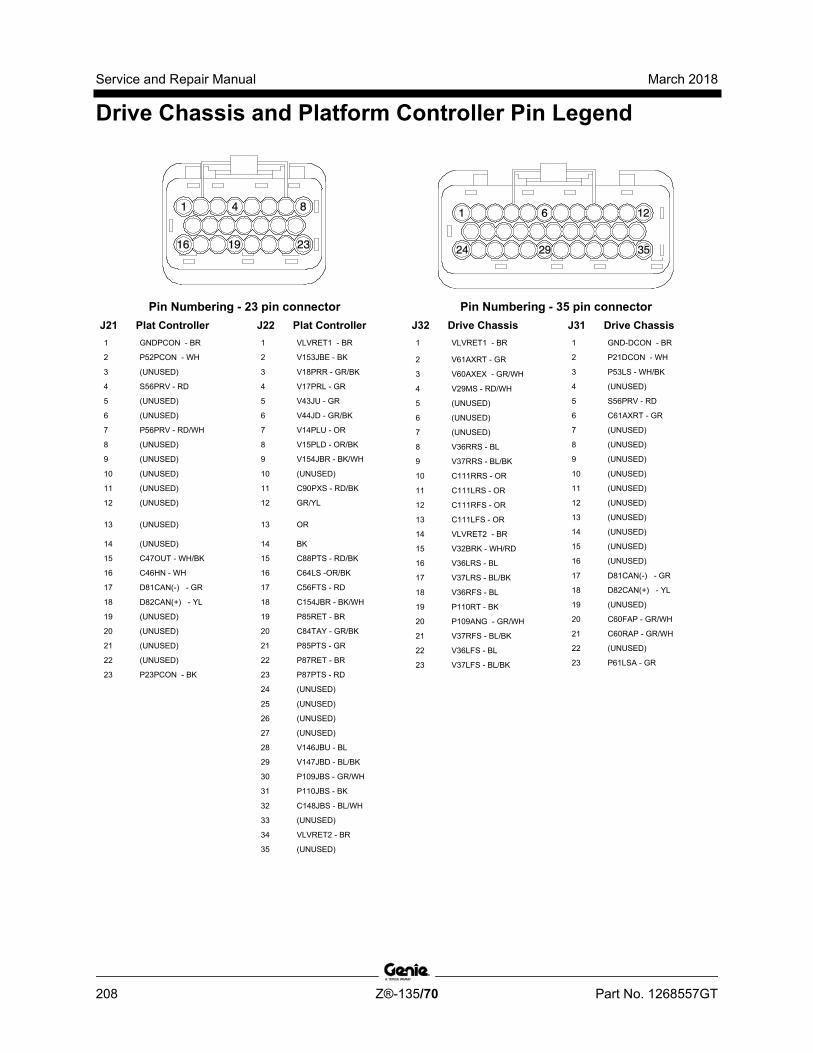
Service and Repair Manual March 2018
Drive Chassis and Platform Controller Pin Legend
208 Z®-135/70 Part No. 1268557GT
Pin Numbering - 23 pin connector Pin Numbering - 35 pin connector
J21 Plat Controller 1 GNDPCON - BR
2 P52PCON - WH
3 (UNUSED)
4 S56PRV - RD
5 (UNUSED)
6 (UNUSED)
7 P56PRV - RD/WH
8 (UNUSED)
9 (UNUSED)
10 (UNUSED)
11 (UNUSED)
12 (UNUSED)
13 (UNUSED)
14 (UNUSED)
15 C47OUT - WH/BK
16 C46HN - WH
17 D81CAN(-) - GR
18 D82CAN(+) - YL
19 (UNUSED)
20 (UNUSED)
21 (UNUSED)
22 (UNUSED)
23 P23PCON - BK
J22 Plat Controller 1 VLVRET1 - BR
2 V153JBE - BK
3 V18PRR - GR/BK
4 V17PRL - GR
5 V43JU - GR
6 V44JD - GR/BK
7 V14PLU - OR
8 V15PLD - OR/BK
9 V154JBR - BK/WH
10 (UNUSED)
11 C90PXS - RD/BK
12 GR/YL
13 OR
14 BK
15 C88PTS - RD/BK
16 C64LS -OR/BK
17 C56FTS - RD
18 C154JBR - BK/WH
19 P85RET - BR
20 C84TAY - GR/BK
21 P85PTS - GR
22 P87RET - BR
23 P87PTS - RD
24 (UNUSED)
25 (UNUSED)
26 (UNUSED)
27 (UNUSED)
28 V146JBU - BL
29 V147JBD - BL/BK
30 P109JBS - GR/WH
31 P110JBS - BK
32 C148JBS - BL/WH
33 (UNUSED)
34 VLVRET2 - BR
35 (UNUSED)
J32 Drive Chassis 1 VLVRET1 - BR
2 V61AXRT - GR
3 V60AXEX - GR/WH
4 V29MS - RD/WH
5 (UNUSED)
6 (UNUSED)
7 (UNUSED)
8 V36RRS - BL
9 V37RRS - BL/BK
10 C111RRS - OR
11 C111LRS - OR
12 C111RFS - OR
13 C111LFS - OR
14 VLVRET2 - BR
15 V32BRK - WH/RD
16 V36LRS - BL
17 V37LRS - BL/BK
18 V36RFS - BL
19 P110RT - BK
20 P109ANG - GR/WH
21 V37RFS - BL/BK
22 V36LFS - BL
23 V37LFS - BL/BK
J31 Drive Chassis 1 GND-DCON - BR
2 P21DCON - WH
3 P53LS - WH/BK
4 (UNUSED)
5 S56PRV - RD
6 C61AXRT - GR
7 (UNUSED)
8 (UNUSED)
9 (UNUSED)
10 (UNUSED)
11 (UNUSED)
12 (UNUSED)
13 (UNUSED)
14 (UNUSED)
15 (UNUSED)
16 (UNUSED)
17 D81CAN(-) - GR
18 D82CAN(+) - YL
19 (UNUSED)
20 C60FAP - GR/WH
21 C60RAP - GR/WH
22 (UNUSED)
23 P61LSA - GR
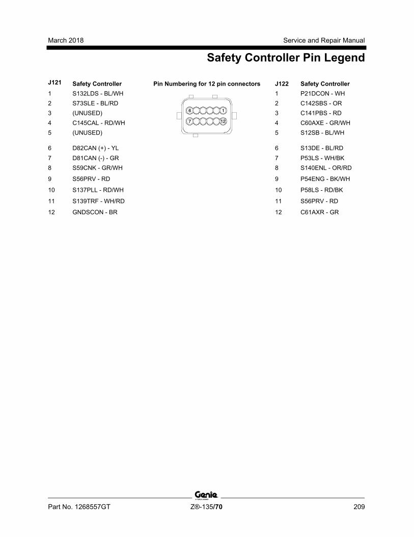
March 2018 Service and Repair Manual
Safety Controller Pin Legend
Part No. 1268557GT Z®-135/70 209
J121 Safety Controller Pin Numbering for 12 pin connectors J122 Safety Controller 1 S132LDS - BL/WH
1 P21DCON - WH 2 S73SLE - BL/RD 2 C142SBS - OR 3 (UNUSED) 3 C141PBS - RD 4 C145CAL - RD/WH 4 C60AXE - GR/WH 5 (UNUSED) 5 S12SB - BL/WH
6 D82CAN (+) - YL 6 S13DE - BL/RD 7 D81CAN (-) - GR 7 P53LS - WH/BK 8 S59CNK - GR/WH 8 S140ENL - OR/RD
9 S56PRV - RD 9 P54ENG - BK/WH
10 S137PLL - RD/WH 10 P58LS - RD/BK
11 S139TRF - WH/RD 11 S56PRV - RD
12 GNDSCON - BR 12 C61AXR - GR

Service and Repair Manual March 2018
Turntable Controller Pin Legend
210 Z®-135/70 Part No. 1268557GT
Pin Numbering - 35 pin connector Pin Numbering - 23 pin connector Pin Numbering - 4 pin connector
J11 Turntable Controller
1 GNDPCON - BR
2 P52PCON - WH
3 C46HN - WH
4 C47OUT - WH/BK
5 P23PCON - BK
6 S56PRV - RD
7 P56PRV - RD/WH
8 (UNUSED)
9 R117FB - RD
10 (UNUSED)
11 C145CAL - RD/WH
12 (UNUSED)
13 (UNUSED)
14 (UNUSED)
15 (UNUSED)
16 (UNUSED)
17 D81CAN(-) - GR
18 D82CAN(+) - YL
19 (UNUSED)
20 (UNUSED)
21 (UNUSED)
22 (UNUSED)
23 (UNUSED)
J15 Turntable Controller
1 B1BAT - RD
2 GND - BR
3 GND - BR
4 (UNUSED)
J12 Turntable Controller
1 GNDSCON - BR
2 P21DCON - WH
3 P53LS - WH/BK
4 P54ENG - BK/WH
5 S56PRV - RD
6 P53LS - WH/BK
7 P58LS - RD/BK
8 S59CNK - GR/WH
9 S140ENL - OR/RD
10 C61AXR - GR
11 (UNUSED)
12 (UNUSED)
13 C64LS - OR/BK
14 C65LOF - BL/WH
15 C144DER - BL/WH
16 C73SBR - BL/RD
17 C67SBD - BL
18 C64LS - OR/BK
19 C70PBR - BL/WH
20 C71PBE - BL/BK
21 (UNUSED)
22 (UNUSED)
23 (UNUSED)
24 (UNUSED)
25 SNSR GND - BR
26 P109ANG - GR/WH
27 (UNUSED)
28 C143DEL - BL/RD
29 (UNUSED)
30 (UNUSED)
31 (UNUSED)
32 C123PBS - RD/BK
33 C124SBS - OR/BK
34 S140ENL - OR/RD
35 GND16 - BR
J13 Turntable Controller
1 (UNUSED)
2 C35RPM - BK/RD
3 C21IGN - WH
4 C34SA - BK/WH
5 (UNUSED)
6 (UNUSED)
7 C46HRN - WH
8 (UNUSED)
9 C33STR - BK
10 C30EDC - WH
11 C31EDC - WH/BK
12 C25PSR - WH/BK
13 C26TSR - WH/RD
14 (UNUSED)
15 (UNUSED)
16 (UNUSED)
17 S137PLL - RD/WH
18 C41RPM - OR/BK
19 S139TRF - WH/RD
20 (UNUSED)
21 (UNUSED)
22 C45GEN - GR/WH
23 (UNUSED)
J14 Turntable Controller 1 VLVRET4 - BR
2 V03PUD - RD/WH
3 V09PER - BK/RD
4 V06TRF - WH/RD
5 V12SUD - BL/WH
6 V176SER - GR/WH
7 VO1PBU - RD
8 V02PBD - RD/BK
9 V07PBE - BK
10 V08PBR - BK/WH
11 (UNUSED)
12 V11SBD - BL/BK
13 (UNUSED)
14 VLVRET5 - BR
15 (UNUSED)
16 (UNUSED)
17 VLVRET5 - BR
18 VLVRET5 - BR
19 V10SBU - BL
20 V73SBR - GR/BK
21 V72SBE - GR
22 (UNUSED)
23 (UNUSED)
24 (UNUSED)
25 V04TRL - WH
26 V05TRR - WH/BK
27 VLVRET7 - BR
28 (UNUSED)
29 (UNUSED)
30 VLVRET6 - BR
31 (UNUSED)
32 C27AUX - RD
33 (UNUSED)
34 V155PCE - OR/RD
35 V150HG - GR/BK
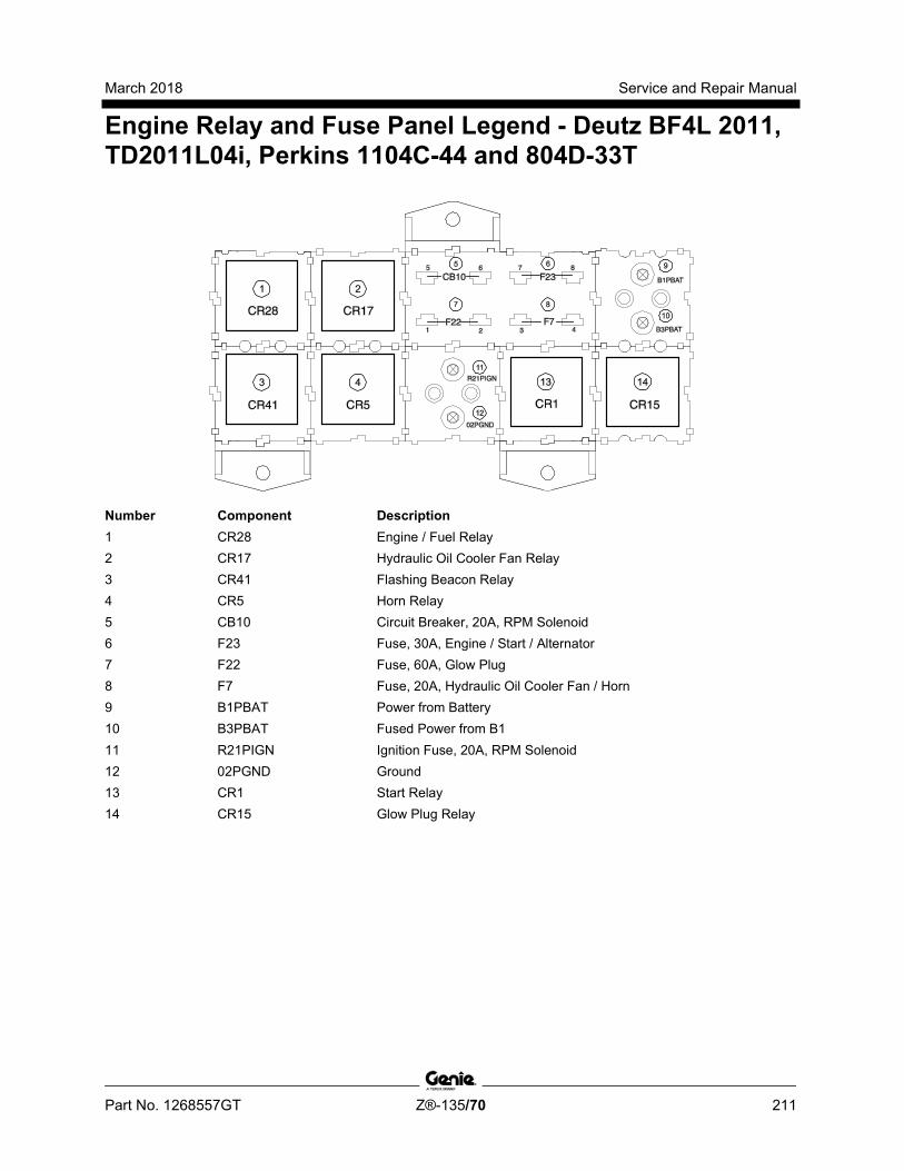
March 2018 Service and Repair Manual
Engine Relay and Fuse Panel Legend - Deutz BF4L 2011, TD2011L04i, Perkins 1104C-44 and 804D-33T
Part No. 1268557GT Z®-135/70 211
Number Component Description 1 CR28 Engine / Fuel Relay 2 CR17 Hydraulic Oil Cooler Fan Relay 3 CR41 Flashing Beacon Relay 4 CR5 Horn Relay 5 CB10 Circuit Breaker, 20A, RPM Solenoid 6 F23 Fuse, 30A, Engine / Start / Alternator 7 F22 Fuse, 60A, Glow Plug 8 F7 Fuse, 20A, Hydraulic Oil Cooler Fan / Horn 9 B1PBAT Power from Battery 10 B3PBAT Fused Power from B1 11 R21PIGN Ignition Fuse, 20A, RPM Solenoid 12 02PGND Ground 13 CR1 Start Relay 14 CR15 Glow Plug Relay
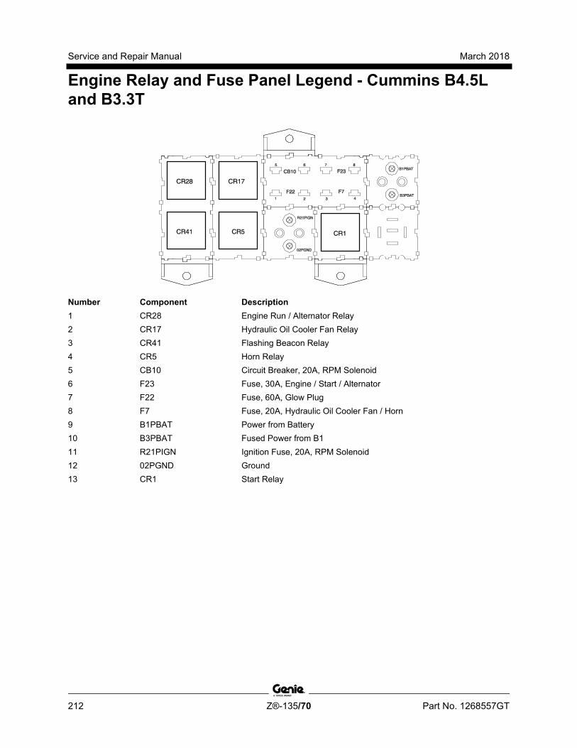
Service and Repair Manual March 2018
Engine Relay and Fuse Panel Legend - Cummins B4.5L and B3.3T
212 Z®-135/70 Part No. 1268557GT
Number Component Description 1 CR28 Engine Run / Alternator Relay 2 CR17 Hydraulic Oil Cooler Fan Relay 3 CR41 Flashing Beacon Relay 4 CR5 Horn Relay 5 CB10 Circuit Breaker, 20A, RPM Solenoid 6 F23 Fuse, 30A, Engine / Start / Alternator 7 F22 Fuse, 60A, Glow Plug 8 F7 Fuse, 20A, Hydraulic Oil Cooler Fan / Horn 9 B1PBAT Power from Battery 10 B3PBAT Fused Power from B1 11 R21PIGN Ignition Fuse, 20A, RPM Solenoid 12 02PGND Ground 13 CR1 Start Relay
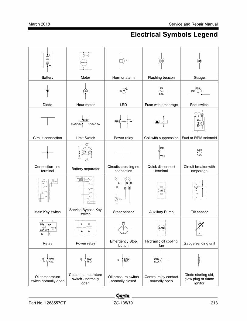
March 2018 Service and Repair Manual
Electrical Symbols Legend
Part No. 1268557GT Z®-135/70 213
Battery Motor Horn or alarm Flashing beacon Gauge
Diode Hour meter LED Fuse with amperage Foot switch
Circuit connection Limit Switch Power relay Coil with suppression Fuel or RPM solenoid
Connection - no terminal Battery separator Circuits crossing no
connection Quick disconnect
terminal Circuit breaker with
amperage
Main Key switch Service Bypass Key switch Steer sensor Auxiliary Pump Tilt sensor
Relay Power relay Emergency Stop button
Hydraulic oil cooling fan Gauge sending unit
Oil temperature switch normally open
Coolant temperature switch - normally
open
Oil pressure switch normally closed
Control relay contact normally open
Diode starting aid, glow plug or flame
ignitor
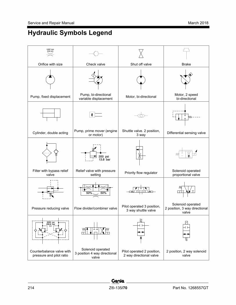
Service and Repair Manual March 2018
Hydraulic Symbols Legend
214 Z®-135/70 Part No. 1268557GT
Orifice with size Check valve Shut off valve Brake
Pump, fixed displacement Pump, bi-directional variable displacement Motor, bi-directional Motor, 2 speed
bi-directional
Cylinder, double acting Pump, prime mover (engine or motor)
Shuttle valve. 2 position, 3 way Differential sensing valve
Filter with bypass relief valve
Relief valve with pressure setting Priority flow regulator Solenoid operated
proportional valve
Pressure reducing valve Flow divider/combiner valve Pilot operated 3 position, 3 way shuttle valve
Solenoid operated 2 position, 3 way directional
valve
Counterbalance valve with pressure and pilot ratio
Solenoid operated 3 position 4 way directional
valve
Pilot operated 2 position, 2 way directional valve
2 position, 2 way solenoid valve
March 2018 Service and Repair Manual
215
Perkins 1104C-44 and 804D-33T Engine Electrical Schematic
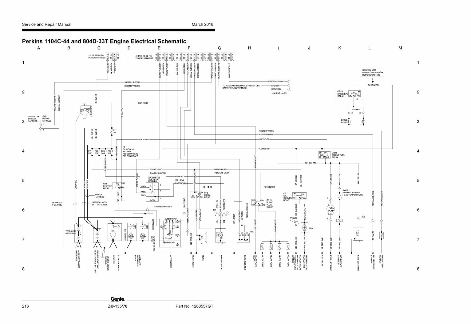
Service and Repair Manual March 2018
216 Z®-135/70 Part No. 1268557GT
Perkins 1104C-44 and 804D-33T Engine Electrical Schematic
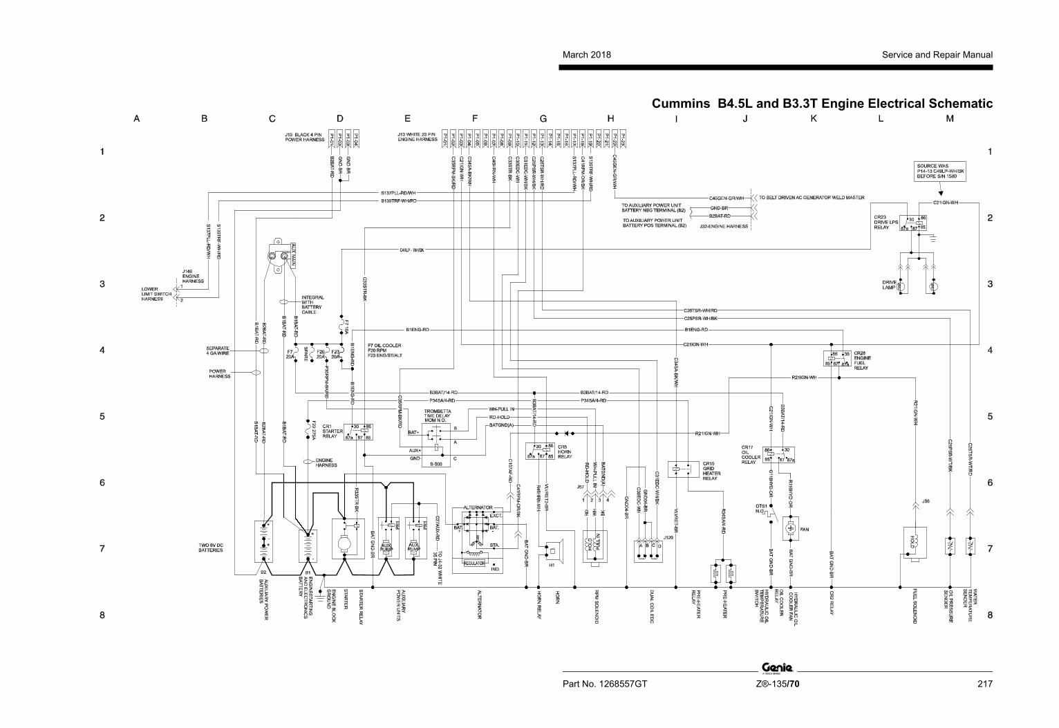
March 2018 Service and Repair Manual
Part No. 1268557GT Z®-135/70 217
Cummins B4.5L and B3.3T Engine Electrical Schematic
Service and Repair Manual March 2018
218
Cummins B4.5L and B3.3T Engine Electrical Schematic
March 2018 Service and Repair Manual
219
Generator Wiring Schematic

Service and Repair Manual March 2018
220 Z®-135/70 Part No. 1268557GT
Generator Wiring Schematic
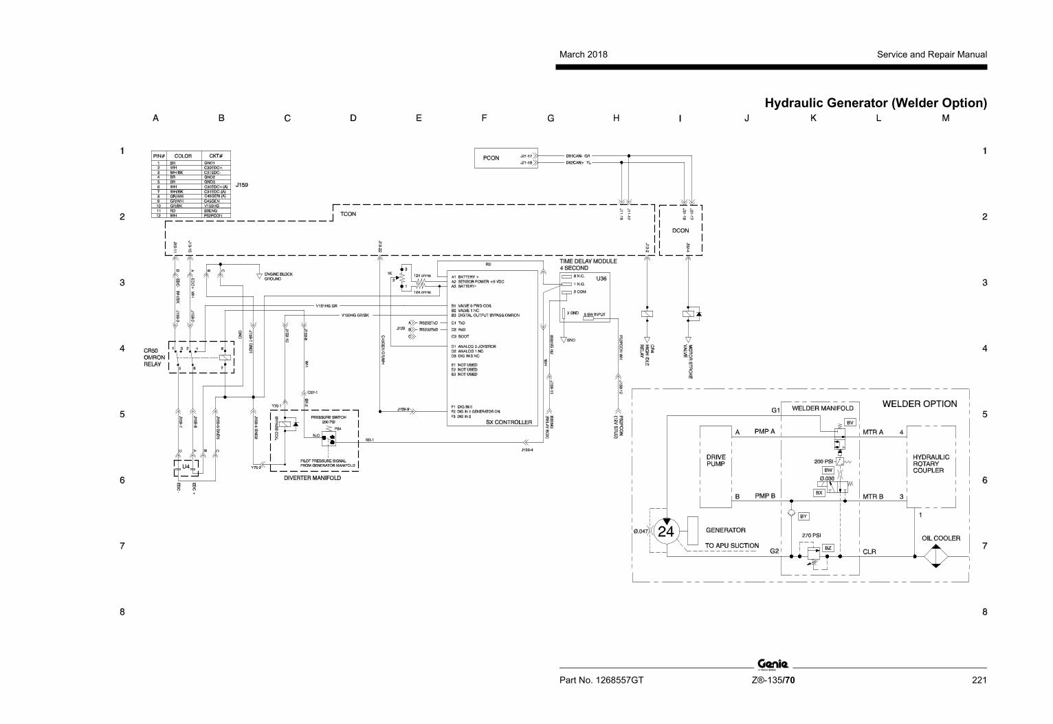
March 2018 Service and Repair Manual
Part No. 1268557GT Z®-135/70 221
Hydraulic Generator (Welder Option)
Service and Repair Manual March 2018
222
Hydraulic Generator (Welder Option)

March 2018 Service and Repair Manual
223
Hydraulic Schematic (before serial number 180, except for serial number 102)

Service and Repair Manual March 2018
224 Z®-135/70 Part No. 1268557GT
Hydraulic Schematic (before serial number 180, except for serial number 102)

March 2018 Service and Repair Manual
Part No. 1268557GT Z®-135/70 225
Hydraulic Schematic (serial number 102 and from serial number 180 to 534)
Service and Repair Manual March 2018
226
Hydraulic Schematic (serial number 102 and from serial number 180 to 534)
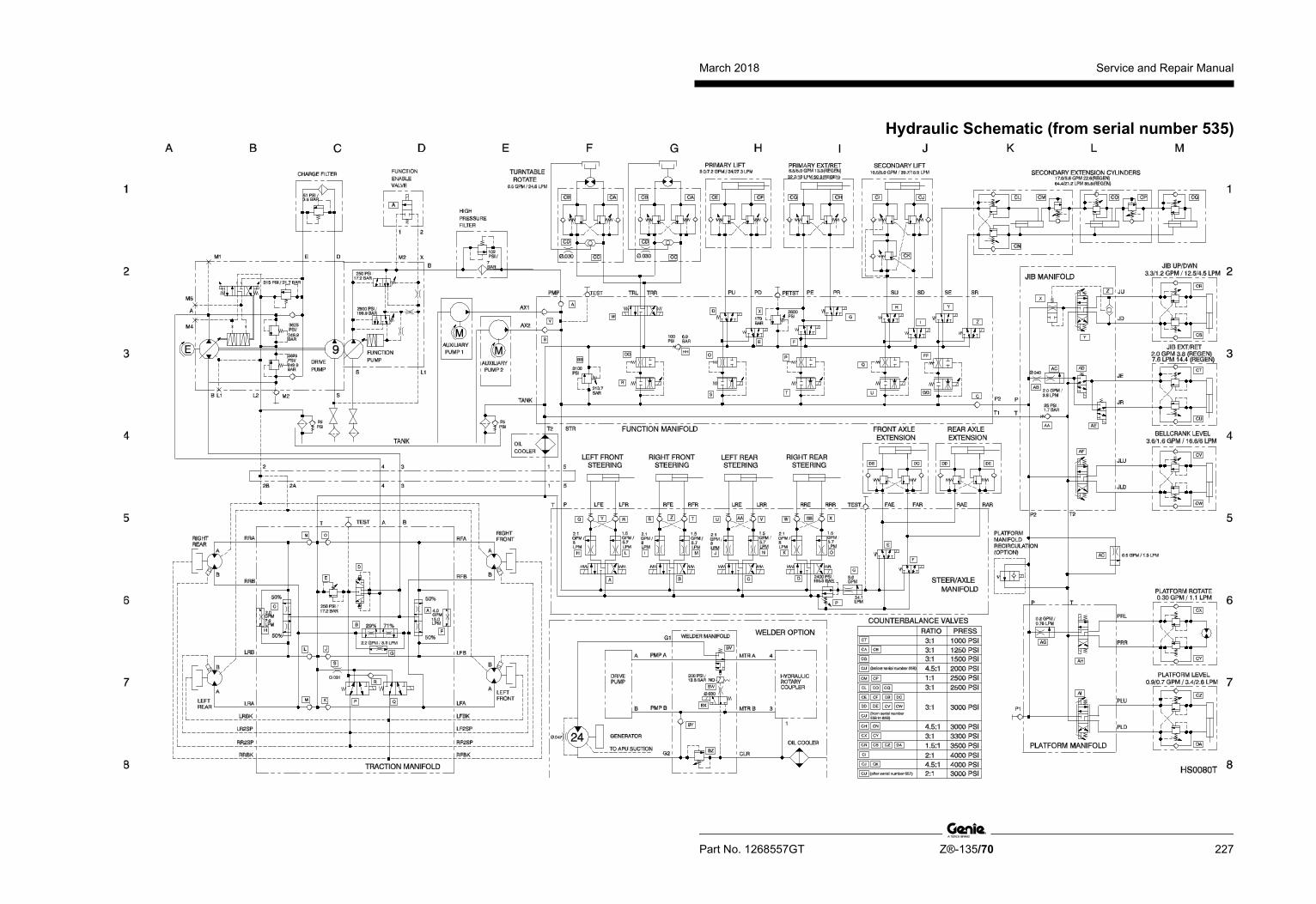
March 2018 Service and Repair Manual
Part No. 1268557GT Z®-135/70 227
Hydraulic Schematic (from serial number 535)
Service and Repair Manual March 2018
228
Hydraulic Schematic (from serial number 535)
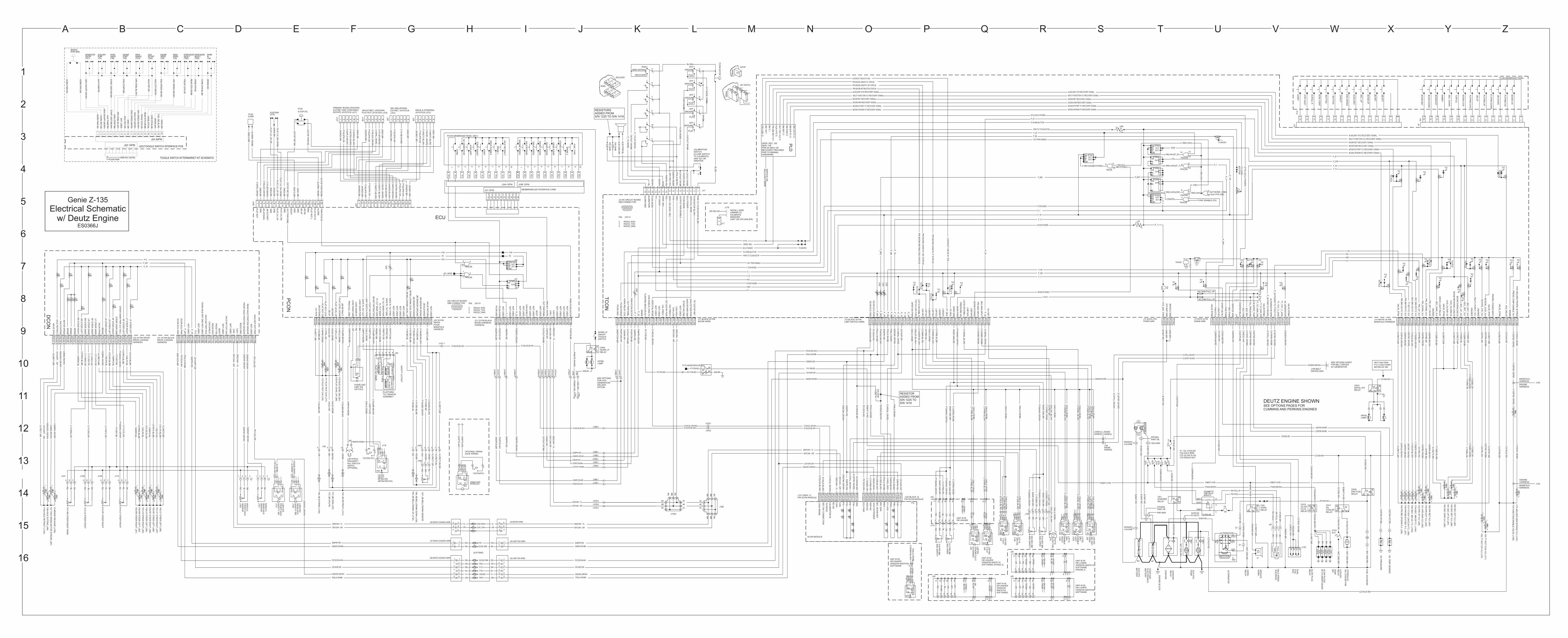
A B C D E F G H I J K L M N O P Q R S T U V W X Y Z
1
2
3
4
5
6
7
8
9
10
11
12
13
14
15
16
8685
87
87a30
SLIP RING
SCON MODULE
TO FLASHING BEACON
S56PRV-RD
GNDDCON-BR
P21DCON-WH
R11
7F
B-R
D
P5
6P
RV
-RD
/WH
S5
6P
RV
-RD
C4
7O
UT-W
H/B
K
C4
6H
N-W
H
P5
2P
CO
N-W
H
GN
DP
CO
N-B
R
P2
3P
CO
N-B
K
D8
1C
AN
- -GR
D8
2C
AN
+ -Y
L
P11
-03
P11
-02
P11
-01
P11
-04
P11
-05
P11
-08
P11
-06
P11
-07
HO
RN
RE
LA
Y C
OIL
PC
ON
PO
WE
R
PC
ON
GN
D
TC
ON
OU
T P
WR
EN
BL
PW
R-P
CO
N E
ST
OP
SP
AR
E
P_
22
P_
7
P11
-14
P11
-09
P11
-10
P11
-11
P11
-13
P11
-12
P11
-16
P11
-15
P11
-17
P11
-19
P11
-18
CA
L F
RE
Q 1
FL
AS
HIN
G B
EA
CO
N R
LY
CA
N S
HIE
LD
(19
39
-11)
NO
T U
SE
D
TE
T E
ST
OP
PW
R
CA
L F
RE
Q 2
CA
N L
OW
NO
T U
SE
D
CA
N H
IGH
TE
T E
ST
OP
RE
T
P11
-20
P11
-21
P11
-22
P11
-23
TETH
ER
FUN
C E
NB
L
DIA
G/T
ET
HE
R G
ND
DIA
G/T
ET
HE
R P
WR
BM
U/D
FC
O
PR
I BM
RE
T S
T I
AU
X H
YD
O
MLT
FN
C V
LV O
BM
RE
T O
BM
E/R
FC
O
BM
DW
N O
OPER. REC. OR SERV. ORPWR IN SERV OR RECOVERY PROVIDES PWR TO MINIMAL HARDWARE
PL
D
OPTIONAL SWINGGATE WIRING
FOOTSWITCH
ECU
Y1
9 P
LA
T L
EV
EL D
N (J8
1)
Y2
0 P
LA
T L
EV
EL U
P (J8
0)
Y7
0 P
LA
T R
OT
CW
(J76
)
Y7
1 P
LA
T R
OT
CC
W (J7
7)
Y7
3 JIB
DW
N (J7
9)
Y7
2 JIB
UP
(J78)
FOOTSW (FS1)
SWING GATEINTERLOCK
LIM
IT S
WIT
CH
PW
RP
22
-16
P2
2-1
5
P2
2-1
4
P2
2-1
3
P2
2-1
2
P2
2-1
0
P2
2-11
P2
2-0
9
P2
2-0
8
P2
2-0
7
P2
2-0
6
P2
2-0
5
P2
2-0
4
P2
2-0
3
P2
2-0
2
P2
2-0
1
V1
8P
RR
-GR
/BK
VLV
RE
T2
-BR
V1
7P
RL
-GR
R90PXS-RD/BK
V1
5P
LD
-OR
/BK
V4
4JD
-GR
/BK
V1
4P
LU
-OR
V4
3JU
-GR
C8
8P
TS
-RD
/BK
C9
0P
XS
-RD
/BK
PL
AT
RO
T C
W
VLV
RT
N
PL
AT
RO
T C
CW
JIB U
P
JIB D
WN
PL
AT
LE
VE
L U
P
PL
AT
LE
VE
L D
OW
N
SA
FE
PL T
ILT O
UT
PR
OX
KIL
L C
MD
P2
2-2
3
P2
2-2
1
P2
2-2
2
P2
2-1
9
P2
2-1
8
P2
2-1
7
P2
2-2
0C
84
TA
Y-G
R/B
K
P8
5P
TS
-GR
P8
5R
ET-B
R
P8
7P
TS
-RD
P8
7R
ET-B
R
C2
3P
TS
-WH
C56
PT
S-R
D
PL T
ILT S
NS
R
FO
OT
SW
RT
N
PL T
ILT S
NS
R P
WR
PL T
ILT S
NS
R G
ND
SA
FE
PL T
ILT P
WR
SA
FE
PL T
ILT G
ND
U2
0
J16
9
21 3 64 5 7 8 109 11
13
12
14
17
15
16
18
19
20
GN
D1
2-B
R
AL
AR
M+
RD
/BK
ALARMPCON
J12
8
PL
AT
LVL U
P-O
R
PL
AT
LVL D
N-O
R/B
K
GN
D6
-BR
JSG
ND
4-B
R
J12
7
1
C1
64
PL
S-R
D/W
H
C1
65
TR
S-W
H/R
D
P1
62
JPW
-OR
42 3 5 6
LEVELPLATFORM
C1
56
JUD
-GR
/WH
P1
62
JPW
-OR
JSG
ND
3-B
R
JSG
ND
2-B
R
P1
62
JPW
-OR
J28
JSG
ND
1-B
R
C1
59
ST
C-B
L/W
H
C1
60
JPL
-WH
/RD
C1
58
ST
C-B
L/R
D
C1
61
SB
-WH
/BK
J25
P2
1-0
3
P2
1-0
1
P2
1-0
2P
52
PC
N-W
H
GN
DP
CN
-BR
PC
ON
GN
D
PC
ON
PW
R
P2
1-0
4
P2
1-0
5
P2
1-0
6
P2
1-0
7
P2
1-0
8
P2
1-0
9
P2
1-11
P2
1-1
0
P2
1-1
2
P2
1-1
3
P2
1-1
4
P2
1-1
5
P2
1-2
0
P2
1-1
6
P2
1-1
7
P2
1-1
8
P2
1-1
9
P2
1-2
2
P2
1-2
1
P2
1-2
3
S5
6P
RV
-RD
P5
6P
RV
-RD
/WH
C4
7O
UT-W
H/B
K
D8
1C
AN
-GR
D8
2C
AN
+ -Y
L
C4
6H
N-W
H
P2
3P
CN
-BK
P_
7
P_
22
OU
T P
WR
EN
BL
HR
N R
LY C
NT
RL
CA
N H
CA
N L
PW
R-P
CO
N E
ST
OP
P1
MEMBRANE/LED INTERFACE CARD
J24A 10PIN
P1
P1
1 2
1 2 3
J23 10PIN
5
P1
P1
P1
3 4
P1
P1
6 7
P6
P7R
3
954 6 7 8 10
J24B 10PIN
P1
P1
8 9 10
P2
P2
P2
1 2
P2
P2
P2
4 5
P2
P2
6 7 8
P2
P2
109
PCON MEMBRANE PANEL (MS1)
HO
RN
ES
TO
P R
ET
-BK
ES
TO
P P
WR
-RD
STA
RT
AS
SIS
T
AC
GE
NE
RA
TO
R
AU
XIL
IAR
Y
DR
IVE
EN
AB
LE
STA
RT
PCON
E-STOP (P2)
AX
LE
RE
TR
AC
T
SP
AR
E 1
EN
GIN
E S
PE
ED
DR
IVE
SP
EE
D
AX
LE
EX
TE
ND
FR
ON
T S
TE
ER
CR
AB
ST
EE
R
CO
OR
D S
TE
ER
FU
EL T
YP
E
D81CAN- -GR
D82CAN+ -YL
P56PRV-RD/WH
GNDPCON-BR
P23PCON-BK
P52PCON-WH
S56PRV-RD
C46HN-WH
Y5
7-L
R S
TE
ER
RIG
HT
(J93
)
S11
-RR
ST
EE
R R
IGH
T S
NS
R
Y2-B
RA
KE
RE
LE
AS
E (J1
06)
Y2
7-T
WO
SP
EE
D M
OT
OR
ST
RO
KE
(J87
)
BL
RD
BA
S14
-LF
ST
EE
R R
IGH
T
S1
3-R
F S
TE
ER
RIG
HT
S1
2-L
R S
TE
ER
RIG
HT
Y55
-RR
ST
EE
R R
IGH
T (J9
1)
Y5
6-R
R S
TE
ER
LE
FT
(J92
)
C
BK
Y6
0-R
F S
TE
ER
LE
FT
(J96
)
Y6
1-L
F S
TE
ER
RIG
HT
(J97
)
Y6
2-L
F S
TE
ER
LE
FT
(J98
)
Y5
9-R
F S
TE
ER
RIG
HT
(J95
)
Y5
8-L
R S
TE
ER
LE
FT
(J94
)
V3
7L
FS
-BL
/BK
V3
6L
FS
-BL
V3
7R
FS
-BL
/BK
P1
09
AN
G-G
R/W
H
V3
2B
RK
-WH
/RD
V3
6R
FS
-BL
V3
7L
RS
-BL
/BK
V3
6L
RS
-BL
P11
0R
T-B
K
C111
LF
S-O
R
C111
RF
S-O
R
C111
LR
S-O
R
C111
RR
S-O
R
V3
7R
RS
-BL
/BK
V3
6R
RS
-BL
VLV
RE
T2
-BR
VLV
RE
T1
-BR
V2
9M
S-R
D/W
H
SP
AR
E
SP
AR
E
MO
TO
R S
PE
ED
VA
LVE
RT
N1
P3
2-0
3
P3
2-0
6
P3
2-0
5
P3
2-0
4
P3
2-0
2
P3
2-0
1
P3
2-0
7
LR
ST
EE
R L
EF
TP
32
-17
LR
ST
EE
R R
IGH
T
VA
LVE
RT
N2
LF
ST
EE
R S
NS
R
BR
AK
E
RR
ST
EE
R R
IGH
T
RR
ST
EE
R L
EF
T
RR
ST
EE
R S
NS
R
LR
ST
EE
R S
NS
R
RF
ST
EE
R S
NS
R
P3
2-1
0
P3
2-1
6
P3
2-1
5
P3
2-1
4
P3
2-1
2
P3
2-1
3
P3
2-11
P3
2-0
9
P3
2-0
8
LF
ST
EE
R R
IGH
T
RF
ST
EE
R L
EF
T
ST
EE
R S
NS
R P
WR
(5.0
VD
C)
ST
EE
R S
NS
R G
ND
LF
ST
EE
R L
EF
T
P3
2-2
1
P3
2-2
3
P3
2-2
2
P3
2-1
9
P3
2-2
0
P3
2-1
8R
F S
TE
ER
RIG
HT
D8
2C
AN
+ -Y
L
D8
1C
AN
- -GR
C6
1A
XR
T-G
R
S5
6P
RV
-RD
P5
3L
S-W
H/B
K
P2
1D
CN
-WH
GN
D-D
CN
-BR
DC
ON
EC
U G
ND
AX
LE
NO
T R
ET
RT
N
DIG
IN A
XL
E R
ET
GN
D N
OT
US
ED
P1
2
P_
7R
P_
6R
1
DC
ON
EC
U P
WR
P3
1-0
1
P3
1-0
2
P3
1-0
4
P3
1-0
5
P3
1-0
6
P3
1-0
7
P3
1-0
8
P3
1-0
9
P3
1-0
3
RS
23
2 G
ND
P3
1-1
9
CA
N +
CA
N -
AX
LE
NO
T E
XT
SIG
BO
OT
RS
23
2 T
XD
RS
23
2 R
XD
CA
N S
HIE
LD
P3
1-11
P3
1-1
3
P3
1-1
2
P3
1-1
4
P3
1-1
5
P3
1-1
6
P3
1-1
7
P3
1-1
8
P3
1-1
0
AX
LE
NO
T E
XT
PW
R
P3
1-2
0
P3
1-2
2
P3
1-2
3
P3
1-2
1
SP
AR
E
J32 23 PIN WHITEDRIVE CHASSISHARNESS
J31 23 PIN BLACKDRIVE CHASSISHARNESS
C1
54
JBR
-BK
/WH
PLATFORM TILT SENSORASSEMBLY
LSP1PROXPROXIMITYKILL SWITCH(NOHC)OPTIONAL
PIN CKT # 2 RS232_RXD3 RS232_TXD5 RS232_GND
U3
0
+ -
5
+ -
+ -
21 3 4 6
PIN CKT # 2 RS232_RXD3 RS232_TXD5 RS232_GND
ON CIRCUIT BOARDDB9 CONNECTOR
J107 J108 J109 J110
J82
J119
J84
21
JIB N
OT
RE
TR
AC
TE
D
1 2
P6
P7R
P774HC08
SLP_MODE1
2
3
5
4 6P22
PR
I AN
G IN
PU
T
SN
SR
PW
R
DC
ON
EC
U P
WR
SC
ON
EC
U G
ND
OP
ER
SW
PW
R
PR
ES
SU
RE
GA
SN
SR
GN
D
P1
2-0
4P
_6
R2
P5
4E
NG
-BK
/WH
P5
3L
S-W
H/B
K
P2
1D
CN
-WH
SC
ON
GN
D-B
RP
12
-01
P1
2-0
2
P1
2-0
3P
_6
R1
S5
6P
RV
-RD
C6
4L
S-O
R/B
K
P_
11
P1
2-0
6
P1
2-0
5
P1
2-0
7
P1
2-0
8
P_
9A
P_
7R
P_
9B
P_
10
P1
2-11
P1
2-0
9
P1
2-1
0
P1
2-1
2
P1
2-1
3
P_
14
P_
12
P_
18
P1
SE
QP
12
-23
C6
4L
S-O
R/B
K
C6
5L
OF
-BL
/WH
C6
7S
BD
-BL
C7
1P
BE
-BL
/BK
C7
0P
BR
-BL
/WH
LS
B2
RO.
P1
2-1
8
P1
2-1
6
P1
2-1
4
P1
2-1
5
P1
2-1
7
LS
S1
RO
FS
T1
S-L
OW
FU
EL
LS
T1
0 D
R E
NB
L R
LS
P1
AO
P1
2-2
0
P1
2-1
9
P1
2-2
1
P1
2-2
2
LS
P1
RO
LS
P1
EO
LS
S2
AO
LS
S2
EO
C1
43
DE
L-B
L/R
D
P1
09
AN
G-G
R/W
H
SN
SR
GN
D-B
R
LS
T2
0 D
R E
NB
L L
P1
2-2
5
P1
2-2
4
P1
2-2
6
P1
2-2
7
P2
SE
Q
P1
2-3
0
P1
2-2
9
P1
2-2
8
P1
2-3
2
P1
2-3
1
LS
B1
4A
O
LS
B1
3A
O
PCON POWER
U3
0
U3
1
U3
2
P_6R1
P_11
P_9A
P_7R
P_10
TO
PL
D
TO
PL
D
TO
PL
D
TO
PL
D
PRI BOOM LENGTH 100' STATUS
AUXILIARY HYD RECOVERY SIGNAL
BOOM RET RECOVERY SIGNAL
BOOM DWN RECOVERY SIGNAL
MULTI FUNCTION VLV RECOVERY SIGNAL
BOOM EXT/RET FC RECOVERY SIGNAL
BOOM UP/DWN FC RECOVERY SIGNAL
PRI BOOM RETRACTED STATUS
LOCKOUT VALVE #1 SIG
PRI BOOM LENGTH 3' STATUS
BA
TE
CU
GN
D
SY
S B
AT
GN
D
SY
S_
BA
T_
PW
R
SE
C A
NG
INP
UT
P1
2-3
5
P1
2-3
4
P1
2-3
3
VLV
RE
T
P_
30
CB
20
A
U32
OIL/W
AT
ER
_TE
MP
TT_TILT_SN
SR
_GN
D
OIL
_P
RE
SS
UR
E
ALT
ER
NA
TO
R R
PM
VA
LVE
RT
N#
2
TT_TILT_SNSR_PWR
TT
_T
ILT_
X_
AX
IS
TT
_T
ILT_
Y_
AX
IS
AC
GE
NE
RA
TO
R
STA
RT
ER
RE
LA
Y
SE
RV
ICE
HR
N
VA
LVE
RT
N#
1
STA
RT
AID
RLY
IGN
/FU
EL
TH
RO
TT
LE
RE
V P
WM
FW
D P
WM
ED
C F
WD
ED
C R
EV
OUT PWR ENABLE
P_9B
TO MICRO
U95
P
Y7
7=
TT
RO
T C
W/C
CW
F.C. (J6
9)
Y76
=P
RI B
M E
XT
/RE
T F.C
. (J61
)
Y45
PR
I BM
UP
/DW
N F.C
. (J58
)
P P
Y66
SE
C E
XT
VLV
(J65
)
Y6
5 S
EC
RE
T V
LV (J6
6)
Y8
2 S
EC
DW
N V
LV (J6
8)
Y8
1 S
EC
UP
VLV
(J67
)
Y7
8=
SE
C. B
M E
R F.C
. (J164
)
Y8
0 P
RI R
ET
VLV
(J63
)
Y22
=P
RI U
P V
LV (J5
9)
Y7
9=
PR
I EX
T V
LV (J6
2)
Y2
1=
PR
I DW
N V
LV (J6
0)
P
V0
6T
RF
-WH
/RD
VLV
RE
T4
-BR
V0
3P
UD
-RD
/WH
V09
PE
R-B
K/R
D
V0
7P
BE
-BK
V02
PB
D-R
D/B
K
V0
1P
BU
-RD
VLV
RE
T5
-BR
V0
8P
BR
-BK
/WH
V11
SB
D-B
L/B
K
V7
2S
BE
-GR
V7
3S
BR
-GR
/BK
V1
0S
BU
-BL
Y5
3 T
T R
OT
CC
W V
LV (J7
1)
Y5
2 T
T R
OT
CW
VLV
(J70)
C0
4T
RL
-WH
C0
5T
RR
WH
/BK
VLV
RT
N7
-BR
VLV
RT
N6
-BR
C2
7A
UX
-RD
P11
V0
6T
RF
-WH
/RD
VLV
RE
T4
-BR
V0
3P
UD
-RD
/WH
V0
9P
ER
-BK
/RD
VA
LVE
_R
TN
4
PR
I BM
E/R
FC
VLV
PR
I BM
U/D
FC
VLV
TT
RO
T F
C V
LV
P1
4-0
2
P1
4-0
1
P1
4-0
3
P1
4-0
4
VLV
RE
T5
-BR
V0
7P
BE
-BK
V0
2P
BD
-RD
/BK
V0
1P
BU
-RD
V11
SB
D-B
L/B
K
V0
8P
BR
-BK
/WH
V1
0S
BU
-BL
VLV
RE
T5
-BR
VLV
RE
T5
-BR
VA
LVE
_R
TN
5
P1
4-1
4
SE
C_
DW
N_
VLV
DR
IVE
LIG
HT
RE
LA
Y
PR
I_D
OW
N_
VLV
PR
I_U
P_
VLV
PR
I_E
XT
EN
D_
VLV
PR
I_R
ET
_V
ALV
E
P1
4-0
9
P1
4-0
7
P1
4-0
5
P1
4-0
6
P1
4-0
8
P1
4-1
0
P1
4-11
P1
4-1
3
P1
4-1
2
SE
C_
EX
T_
VLV
SE
C_
RE
T_
VLV
SE
C_
UP
_V
LV
MU
LTI_
FU
NC
T_
VLV
HY
D_
FILT
ER
1 D
I
HY
D_
FILT
ER
2 D
I
BO
OM
RE
VE
RS
E L
OA
D D
I
BO
OM
OV
ER
LO
AD
DI
P1
4-1
9
P1
4-1
6
P1
4-1
5
P1
4-1
7
P1
4-1
8
P1
4-2
1
P1
4-2
0
P1
4-2
2
P1
4-2
3
TO
PL
D
TO
PL
D
TO
PL
D
TO
PL
D
TO
PL
D
BOOM DWN RECOVERY SIGNAL
AUXILIARY HYD RECOVERY SIGNAL
BOOM RET RECOVERY SIGNAL
MULTI FUNCTION VLV RECOVERY SIGNAL
BOOM EXT/RET FC RECOVERY SIGNAL
BOOM UP/DWN FC RECOVERY SIGNAL
P_22R
P_30
PR
ES
S C
OM
P E
NA
BL
E V
LV
VLV
RE
T7
-BR
V0
4T
RL
-WH
V0
5T
RR
-WH
/BK
VLV
RE
T6
-BR
C2
7A
UX
-RD
SP
AR
EP
14
-33
VA
LVE
_R
TN
6
AU
X_
RE
LA
Y
VA
LVE
_R
TN
7
RO
TA
TE
_C
W_
VLV
RO
TA
TE
_C
CW
_V
LV
P1
4-2
8
P1
4-2
6
P1
4-2
5
P1
4-2
4
P1
4-2
7
P1
4-3
0
P1
4-2
9
P1
4-3
1
P1
4-3
2
P1
4-3
5
P1
4-3
4
TO
PL
D
P6R1
P11
P_22
P9A
TO HORN BUTTON
PWR TO TCON ESTOP
P_30
74HC08
74HC08
74HC08
74HC08
U22
U21
GND
14 12
13
8
10
9
6
5
4
3
1
2
P_1
P_
7
P_
7
P_
7R
P7R
P22R
4
5 AUX HYD (AH)(~SM)+(AH)
(OE)
((~SM)+(AH))(OE)
(~S
M)+
(AH
)
P_7
P_
6R
1
P_6R2
FUNC ENABLE (FE)(TM)(FE)
V1
0S
BU
-BL
BOOM STOWED
P_7
SE
C B
M E
/R F
C V
LV
ES
TO
P P
WR
-RD
/BK
AL
AR
M+
RD
/BK
GN
D1
2-B
R
ES
TO
P R
ET
-BK
PL
AT
LVL D
N-O
R/B
K
PL
AT
LVL U
P-O
R
GN
D6
-BR
1 5432 9 10
14
12
1311
76 8 16
15
JSG
ND
1-B
R
P1
62
JPW
-OR
JSG
ND
4-B
R
P1
62
JPW
-OR
C1
65
TR
S-W
H/R
D
C1
64
PL
S-R
D/W
H
C1
63
PE
S-B
L/W
H
C1
61
SB
-WH
/BK
C1
58
ST
C-B
L/R
D
C1
59
ST
C-B
L/W
H
C1
60
JPL
-WH
/RD
P1
62
JPW
-OR
JSG
ND
3-B
R
P1
62
JPW
-OR
JSG
ND
2-B
R
74HC08
VbbBTS621
IN2IN1 OUT 1
ST OUT 2
VbbOUT
ISIN
BTS650
VbbOUT
INIS
BTS650
VbbOUT
INIS
BTS650
VbbOUT
IN
IS
BTS650
GND
Vbb BTS621IN1IN2ST OUT 2
OUT 1
ST OUT 2GND
Vbb
IN2IN1
BTS621OUT 1
P117FB-RD
GND-BR
7
14
74HC08
12V5VGND
(P15)+(ECU POWER)
TO
HO
RN
B
UT
TO
N
(P1
5)+
(EC
U P
OW
ER
)
S1
40
EN
L-O
R/R
D
C7
3S
BR
-BL
/RD
P5
8L
S R
D/B
K
NO
BR
BK
RD
WH
21NC
22
1314
2 1
LO
AD
SN
SR
PW
R
LO
AD
SN
SR
GN
D
LO
AD
SN
SR
IN
J150B-3
J149B-1
J149B-2
J150B-1
J148B-1
J147B-1
J151B-B
J151B-A
13
NO
14
WH
RD
BK
BR
4 3 2 1
NC
22 21
P5
3L
S-W
H/B
K
C5
6F
TS
-RD
1074HC08
BTS621
OUT 2OUT 1
VbbIN1IN2STGND
8 9
BO
OM
ST
OW
ED
P2
3P
CO
N-B
K
P5
6P
RV
-RD
S5
6P
RV
-RD
/BK
SR
V R
EC
-WH
P5
3L
S-B
K/W
H
C47O
UT
WH
/BK
SE
RV
ICE
OR
R
EC
OV
ER
Y M
OD
E
OU
TP
UT
PW
R E
NA
BL
E
SE
RV
. OR
OP
ER
. RE
C.
PW
R T
O T
CO
N E
ST
OP
-BL
/BK
TC
ON
ES
TO
P-B
L/W
H
J4 ON CIRCUIT BOARDDB9 CONNECTOR
BL
15
AL
AR
M P
WR
AL
AR
M G
ND
16
PR
I LO
#1
O
EC
U P
OW
ER
P7
R
P6
R1
P2
2
P7
-GN
/WH
P11
OP
ER
. RE
C.
TC
ON
MO
DE
PC
ON
MO
DE
GR
/WH
RD
/WH
OR
/BK
5 468 7910
12
13
14
11 J17123
BM
3' I
BM
10
0' I
TC
ON
ES
TO
P
P2
3P
CO
N-B
K
G-P
MO
DE
GR
/BK
GROUND
TC
ON
MO
DE
P_
7 P
LA
T-G
R/W
H
AL
M P
WR
-BL
AL
M-G
ND
-BR
2
C4
7O
UT
WH
/BK
P_
15
-OR
/BK
C4
7O
UT
WH
/BK
BL
/BK
1
V
4
2
4
3 12
GROUNDW
1
WH
/BK
12
B
PLAT
PLAT
OFF
GROUND
3
Z
12
A
PLAT
OFF
BL/WH
4
2
RECOVERY
SERV BYPASS
RUN
GROUNDX
3
Y
12
D
E
PLAT
OFF
OFF
GROUNDU
1
C
12
PLAT
OFF
OVERLOAD LIMIT SWLSP1OLS
NO
NC
((~SM)+(AH))(BM STOWED)
((~SM)+(AH))(P_22)
(~SM)+(AH)
RD
GR
RD
BK
V6
0A
XE
X-G
R/W
H
V6
1A
XR
T - G
R
Y9
9-A
XLE
EX
TE
ND
(J99
)
Y1
00
-AX
LE
RE
TR
AC
T (J1
00)
13
NO
14
WH
NC
21
RD
BR
BK
22
14
NO
13
22
2 1
WH
BK
BR
RD
21
NC
BLP18BL
YL
GR
5 5
6 6P6R1
88 C60AXE
88
YL
GR
J37-DRIVE CHASSIS HARN
J38-DRIVE CHASSIS HARNRD
OR
BR
22
4 4
3 3
1 1RDDCON PWR
88 P9A
88 P12
88
OR
BR
88
WH
BK22
11
CC
DCON GND88
P7R88
BK
WH
88
J36-DRIVE CHASSIS HARNYL
B B GR
A ACAN HIGH
CAN LOW
88
88
YL
GR
55
66
22
44
33
J35-LIMIT SW HARN11
J34-LIMIT SW HARN
2 2
1 1
CC
J33-BOOM HARN
BB
AA
LS
RA
1E
SR
EA
R A
XLE
S
AF
ET
Y S
WJ1
38
LS
FA
1E
SF
RO
NT
AX
LE
S
AF
ET
Y S
WJ1
37
P6
1L
SA
-GR
P53LS-WH/BK
P21DCON-WH
GNDDCON-BR
S56PRV-RD
D82CAN+ -YL
D81CAN- -GR
LS
P1
E0
3'F
RO
M F
UL
LY
EX
TE
ND
ED
J45
LS
T20
DR
V
EN
AB
LE
L
EF
TJ1
25
LS
S1
R0
SE
C R
ET
O
PE
RJ4
9
RD
BR
WH
BK
14
22NC13
21
NO
C7
3S
BR
-BL
/RDC64
LS
-OR
/BK
C6
5L
OF
L-B
L/W
H
BR
BK
RD
WH
RD
BK
WH
BR
NC
21
NO
13
22
14
1314
NO
NO
232414
22
13
NO
21
NC
LS
T10
DR
V
EN
AB
LE
R
IGH
TJ1
24
BR
WH
BK
RD
C6
4LS
-OR
/BK
C1
44D
ER
-BL/W
H
FR
ON
T A
XL
E P
OS
ITIO
N S
EN
SO
R
RE
AR
AX
LE
PO
SIT
ION
SE
NS
OR
AX
LE
RE
TR
AC
T
AX
LE
EX
TE
ND
P12
P_7R
P_6R1
1 2
BL
RD
3
BK
PRIMARY BOOM UP/DOWN,EXT/RET AND TURNTABLEROTATE JOYSTICK (JC7)
JIB EXT/RET, UP/DOWNPLAT ROT JOYSTICK (JC6)
SEC BM UP/DWNEXT/RET JOYSTICK(JC5)
DRIVE & STEERINGJOYSTICK (JC3)
NO
T U
SE
D
NO
T U
SE
D
NO
T U
SE
D
NO
T U
SE
D
CA
N S
HIE
LD
NO
T U
SE
D
NO
T U
SE
D
NO
T U
SE
D
NO
T U
SE
D
JIB E
XT
EN
D
SE
RV
/CA
L M
OD
E
NO
T U
SE
D LP
VA
LVE
RT
N#
3
J14 WHITE 35 PINMANIFOLD HARNESS
J12 BLACK 35 PINLIMIT SWITCH HARN
J11 BLACK 23 PINBOOM HARN
SE
C B
M U
/D F
C V
LV
UN
US
ED
NO
T U
SE
D
NO
T U
SE
D
NO
T U
SE
D
NO
T U
SE
D
NO
T U
SE
D
JIB R
ET
RA
CT
NO
T U
SE
D
NO
T U
SE
D
NO
T U
SE
D
BO
OT
NO
T U
SE
D
UN
US
ED
UN
US
ED
PR
OP
EL P
OW
ER
INP
UT
HY
D W
EL
DE
R P
RO
PE
L B
YP
AS
S
J22 35 PIN WHITEPCON MANIFOLDHARNESS
J21 23 PIN BLACKBOOM HARNESSHARNESS
((~SM)+(AH))(P_7)
D82CAN+ -YL
D81CAN- -GR
C60
AX
E-G
R/W
H
C61AXR-GR C61AXR-GR
S1
40
EN
L-O
R/R
D
BK
RD
31 2
C60AXE-GR/WH C60AXE-GR/WH
C1
24
SB
S-O
R/B
K
C1
23
PB
S-R
D/B
K
C1
23P
BS
-RD
/BK
C1
24S
BS
-OR
/BK
C1
41
PB
S-R
D
P1
09A
NG
-GR
/WH
P10
9A
NG
-GR
/WH
SN
SR
GN
D-B
R
SN
SR
GN
D-B
R
SN
SR
GN
D-B
R
14NO13
BK
BR
RD
WH
22 21NC
LS
S1R
S 3
' EX
TJ4
6
NO13NC
14
WH
2122
BK
BR
RD
LS
T1
S D
RV
EN
J12
6
C1
44
DE
R-B
L/W
H
C6
7S
BD
-BL
C6
4L
S-O
R/B
K
C7
1P
BE
-BL/B
KC
64
LS
-OR
/BK
C6
4L
S-O
R/B
KC
70
PB
R-B
L/W
H
C64
LS
-OR
/BK
C6
4L
S-O
R/B
K
TCON MODE
P53LS-WH/BK
S1
3D
E-B
L/R
D
C1
43
DE
L-B
L/R
DC
64
LS
-OR
/BK
C6
4L
S-O
R/B
K
S12
SB
-BL/W
H
C1
63
PE
S-B
L/W
H
C1
6P
RL
-OR
/RD
C1
57
JER
-BK
/RD
C1
45
CA
L-R
D/W
H
TOuP
Y8
5 JIB
BE
LLC
RA
NK
UP
(J13
5)
Y8
6 JIB
BE
LL
CR
AN
K D
OW
N (J1
36
)
P1
09
JBS
-GR
/WH
4P3
V1
46
JBU
-BL
S2
1 JIB
BE
LLC
RA
NK
SE
NS
OR
RD
BL
BK
YL
OR
BR
6 5 4
BL
YL
BR
OR
RD BL
BK
46 5321
P1
09
AN
G-G
R/W
H
P1
09
AN
G-G
R/W
H
SN
SR
GN
D-B
R
C1
42
SB
S-O
R
4
BK
BL
RD
4321
A B C
BKBL
RD
RD
BL
BK
A B C
RD
BL
BK
A B C
V1
53
JBE
-BK
V1
54
JBR
-BK
/WH
Y83
JIB R
ET
RA
CT
(J14
1)
Y8
4 JIB
EX
TE
ND
(J140
)
C6
4L
S-O
R/B
K
1 2 3
PL
AT
RO
T
GN
D
JIB E
XT
/RE
T
JIB U
P/D
WN
GN
D
GN
D
PL
AT
LVL U
P
PL
AT
LVL D
N
GN
D
OU
T P
WR
EN
BL
BO
OT
!
GN
D
GN
D
JIB U
P
JIB D
N
GN
D
PL
AT
RO
T L
PL
AT
RO
T R
AL
AR
M
PW
R-P
CN
ES
C1
57
JER
-BK
/RD
C1
56
JUD
-GR
/WH
C1
6P
RL
-OR
/RD
12 1234
4 3 2 14 3 2 1
P5
3L
S-W
H/B
K
P54E
NG
-BK
/WH
S1
39
TR
F-W
H/R
D
S13
7P
LL-R
D/W
H
S5
9C
NK
-GR
/WH
C60A
XE
-GR
/WH
D8
1C
AN
- -GR
SC
ON
GN
D-B
R
P21
DC
N-W
H
C1
42S
BS
-OR
S56
PR
V-R
D
S5
6P
RV
-RD
D8
2C
AN
+ -Y
L
C1
41
PB
S-R
D
C61
AX
R-G
R
S1
3D
E-B
L/R
D
S1
2S
B-B
L/W
H
P5
8L
S-R
D/B
K
S7
3S
LE
-BL
/RD
S140ENL-O
R/R
D
S5
9C
NK
-GR
/WH
RD
/BK
OR
/BK
GR
/BK
BK
/WHW
H/B
K
GR
OR
RD
BL
WH
11 12 2 10 7 6 9 4 8 3
P2
2-2
9
P2
2-2
4
P2
2-2
5
P2
2-2
6
P2
2-2
7
P2
2-2
8
P2
2-3
2
P2
2-3
0
P2
2-3
1
P2
2-3
4
P2
2-3
3
P2
2-3
5
NO
T U
SE
D
NO
T U
SE
D
NO
T U
SE
D
NO
T U
SE
D
JIB B
EL
LC
RA
NK
LE
VE
L U
P
JIB B
ELLC
RA
NK
LE
VE
L DO
WN
JIB S
EN
SO
R P
OW
ER
JIB S
EN
SO
R G
RO
UN
D
JIB S
EN
SO
R S
IGN
AL
JIB E
LE
VA
TE
D
VA
LVE
RE
TU
RN
NO
T U
SE
D
V1
47
JBD
-BL
/BK
P11
0JB
S-B
K
C1
48
JBS
-BL
/WH
9 11 12 10 1 2 3 4 5 6
OR
BK
BK
/WH
OR
/BK
RD
RD
/BK
WH
WH
/BK
GR
/BK
VLV
RE
T1
-GR
C6
0R
AP
-GR
/WH
C6
0FA
P-G
R/W
H
V1
50
HG
GR
/BK
V1
50
HG
GR
/BK
Y7
5 W
EL
DE
R G
EN
BY
PA
SS
VLV
(J16
7)
V1
55
PS
E O
R/R
DY
74
FU
NC
TIO
N E
NA
BLE
VA
LVE
(J166
)
J146
WORK LPON/OFFTOGGLESWITCH
WORKLAMP
(BM STOWED)(~SM)+(AH)
V1
2S
UD
-BL
/WH
V17
6S
ER
-GR
/WH
V12
SU
D-B
L/W
H
P
Y4
6=
SE
C. B
M U
D F.C
. (J16
3)
TO MICRO
654321 1 2 3 4 5 6 654321
GN
D3
-BR
GN
D4
-BR
GN
D2
-BR
GN
D1
-BR
J29
GN
D1
-BR
GN
D2
-BR
GN
D4
-BR
GN
D3
-BR
J121-GRAY 12 PIN SCON MODULE J122-BLACK 12
PIN SCON MODULE
P122-10
P122-11
P122-12
P122-09
P122-04
P122-01
P122-02
P122-03
P122-07
P122-05
P122-06
P122-08
P1
21-0
5
P12
1-0
6
P1
21-0
7
P1
21-0
3
P121-0
4
P1
21-0
8
P12
1-0
9
P1
21-11
P12
1-1
0
P12
1-1
2
P1
21-0
1
P1
21-0
2
P3
9
P3
8
TD
RS
23
2
LO
AD
SE
NS
E
CA
N-
CA
N+
RD
23
2
CA
LIB
RA
TIO
N IN
P1
0
P7
R
P6R
1
EC
U P
WR
RS
S1A
S
RS
P1
AS
AX
LE
EX
TE
ND
ED
P7R
DR
V. E
NA
.
GN
D
P9
B
P11
+P
30
P6
R2
SE
C. B
OO
M R
ET
P1
2
22 21
NO1314NC
BK
BR
RDWH
BA
BB
AA
AB
BA
BB
AA
AB
BA
BB
C6
1A
XR
-GR
AC
BC
J152B
J152A
BA
BC ACJ151B-C
BA
BB
BC
J14
8A
-1
J14
7A
-1
J14
9A
-1
J14
9A
-2
J15
0A
-2
J15
0A
-3
J15
1A
-B
J15
1A
-A
J15
0A
-1
J15
1A
-C
J14
8C
-1
J14
7C
-1
VLV
RE
T2
-BL
7
VLV
RE
T3
-BL/B
K
8J165
VLV
RE
T1
-BR
BK
V1
55
PS
E O
R/R
D
MANIFOLD HARNESS
ENGINE HARNESS
MANIFOLD HARNESS
ENGINE HARNESS
J153
J153
J129-01
C145CAL-RD/WHC145CAL-RD/WH
2
1
SE
RV
/CA
L M
OD
E
P_
38
PW
R T
O P
RO
PE
L
S1
39
TR
F-W
H/R
DP
_3
9 P
OW
ER
TO
TT
RO
T F
C
J20
J114
J154
R117FB-RD R117FB-RD
30
85
86
87a 87
CR45WORK LPRELAY
J15
6
J15
5J1
56
J15
5P
20
BA
T-R
D
GN
D-B
R
GND-BR
P4
8L
PS
-WH
/RD
P12
VLV
RE
T B
R
J2-G
R/B
K
SE
C S
W C
ON
NE
CT
ION
C64
LS
-OR
/BK
C1
45
CA
L-R
D/W
H
S7
3S
LE
-BL
/RD
WH
J15
0A
-4
C47OUT-WH/BKJ150B-2
S132LDS-BL/WHJ150B-4
S132LDS-BL/WH
S1
32
LD
S-B
L/W
H
S132LDS-BL/WH
J55
LSJ1ROJIB NOTRETRACTED(RETRACTED POS)
S132LDS-BL/WH S132LDS-BL/WH
J165
J129-02
J157-1
SEE OPTIONSFOR HYD GENERATOR/WELDER OPTION
V7
3S
BR
-GR
/BK
V7
2S
BE
-GR
V7
3S
BR
-GR
/BK
V7
2S
BE
-GR
V1
76
SE
R-G
R/W
H
2 1
RS
FA
1O
FR
ON
T A
XL
E
SE
NS
OR
J16
0
RS
RA
1O
RE
AR
AX
LE
S
EN
SO
RJ1
61
C60A
XE
-GR
/WH
J2-G
R/B
K
P6
1L
SA
-GR
15
BK
BL
/BK
1
2
1
21 1
2 2
1 1
21
21
22
1
1
2
2
1 1 1 1 1
2 2 2 2 2
1
2
YEL WHT
BLUREDBLU
PUR
1
2
1
2
1
2
1
2
1
2
1
2
1
2
1
2
1 1
2
1 1
2
22
ORNYELORN
ORNRED
C47O
UT
WH
/BK
1
2
45621 3
OR
/BK
RD
/BK
5
J20
671021211 1 3849
UNIT #130OR HIGHER
UNIT #130OR HIGHERVERSION S0675100SOFTWARE
S1
8-P
RI B
M
AN
G S
AF
ET
Y
S1
7-P
RI B
M
AN
G O
PE
R
S19
-SE
C B
M
AN
G O
PE
R
FS
T1S
L
OW
FU
EL
FS
PC
ON
DC
ON
BOOM UP/DWN FC RECOVERY SIGNAL
BOOM DWN RECOVERY SIGNAL
BOOM EXT/RET FC RECOVERY SIGNAL
AUXILIARY HYD RECOVERY SIGNAL
MULTI FUNCTION VLV RECOVERY SIGNAL
BOOM RET RECOVERY SIGNAL
J166
ESTOP
NC 1
2
PA
NE
L
KEY SWITCH
NCD
NC
NC
C
A
NC NC
2
1
E1B
2
1
1
2V
1
W
4
2NC
4Y
4
RECOVERY
33
NO
Z
2NC
U
3 X
PANEL
NO
NC
NO
PA
NE
L
PWR TO TCON ESTOP
S56PRV-RD
P53LS-WH/BK
C60AXE-GR/WH
C61AXR-GR
D82CAN+ -YL
D81CAN- -GR
P117FB-RD
ENGINEHARNESS
C4
6H
N-W
H
D8
2C
AN
+ -Y
L
D81
CA
N-G
R
C4
7O
UT-W
T/B
K
P5
6P
RV
-RD
/WH
S56
PR
V-R
D
GN
DP
CN
-BR
P5
2P
CN
-WH
C6
4L
S-O
R/B
K
C6
4L
S-O
R/B
KC
14
3D
EL
-BL
/RD
C6
4L
S-O
R/B
KC
67
SB
D-B
L
C1
44
DE
R-B
L/W
HC
64
LS
-OR
/BK
C7
3S
BR
-BL
/RD
C6
4L
S-O
R/B
K
C6
5L
OF
L-B
L/W
H
C1
24
SB
S-O
R/B
K
SN
SR
GN
D-B
R
P1
09
AN
G-G
R/W
H
VLV
RE
T B
R
C6
4L
S-O
R/B
K
C6
4L
S-O
R/B
K
C7
0P
BR
-BL
/WH
C6
4L
S-O
R/B
K
C6
4L
S-O
R/B
KC
71
PB
E-B
L/B
K
SN
SR
GN
D-B
R
P1
09
AN
G-G
R/W
H
C1
23
PB
S-R
D/B
K
P5
8L
S-R
D/B
K
P5
4E
NG
-BK
/WH
S1
40
EN
L-O
R/R
D
P2
1D
CN
-WH
SC
ON
GN
D-B
R
S5
6P
RV
-RD
P5
3L
S-W
H/B
K
B3BAT/14-RD
B3
BA
T/1
4-R
D
S5
9C
NK
-GR
/WH
C1
48
JBS
-BL
/WH
P11
0JB
S-B
K
V1
47
JBD
-BL
/BK
V1
46
JBU
-BL
P1
09
JBS
-GR
/WH
VLV
RE
T2
-BR
C9
0P
XS
-RD
/BK
V1
54
JBR
-BK
/WH
V4
4JD
-GR
/BK
V4
3JU
-GR
V1
53
JBE
-BK
C1
54
JBR
-BK
/WH
C6
4L
S-O
R/B
K
C5
6F
TS
-RD
C6
0R
AP
-GR
/WH
C6
0F
AP
-GR
/WH
V6
1A
XR
T - G
R
V6
0A
XE
X-G
R/W
H
V2
9M
S-R
D/W
H
VLV
RE
T1
-BR
V3
2B
RK
-WH
/RD
C111
RR
S-O
R
C111
LR
S-O
R
C111
RF
S-O
R
C111
LF
S-O
R
VLV
RE
T2
-BR
V3
7L
FS
-BL
/BK
V3
6LF
S-B
L
V3
7R
FS
-BL
/BK
V3
7L
RS
-BL
/BK
V3
6R
FS
-BL
V3
6L
RS
-BL
V3
7R
RS
-BL
/BK
V3
6R
RS
-BL
P1
09
AN
G-G
R/W
H
P11
0R
T-B
K
P_
6R
2
P11
82 OHM PULL UP
100 OHM PULL UP
5 VOLT
5 V
OLT
5 VOLT
TOuP
TOuP
TOuP
TOuP
TOuPTO
uP
TOuP
TOuP
TOuP
TOuP
TOuP
TOuP
TOuP
TOuP
TOuP
TOuP
TOuP
TOuP
TOuP
TOuP
TOuP
TOuP
TOuP
TOuP
TOuP
TOuPTOuP
TOuP
TOuP
TOuP
TOuP
TOuP
P6
1LS
A-G
R
P15
OPER. REC.
ECU POWER
P11
P6R1
P7R
PCON POWER
P_7
TCON MODE
OUT PWR ENABLE
P_22
TO HORN BUTTON
P_6R2
P_
10
P_
9B
PR
I BO
OM
RE
TR
AC
TE
D S
TA
TU
S
PR
I BO
OM
LE
NG
TH
10
0' S
TA
TU
S
PR
I BO
OM
LE
NG
TH
3' S
TA
TU
S
LO
CK
OU
T V
ALV
E #
1 S
IG
P_
30
J175
INSTALL WIRE JUMPER TO CALIBRATESENSORS(UNIT 320 OR EARLIER)
2
1
3
CALIBRATIONSWITCH(CLOSE SWITCHTO CALIBRATE)UNIT 321 ORGREATER
SRV REC-WH
3
J17
4 3 2 12 1
12 1234
UNIT #129OR LOWERVERSION S0675110SOFTWARE (PHASE 2)
9 4111 12 2 10 7 6
J20
5
BK
/WH
WH
/BK
BL/B
K
GR
BK
RD
/BK
OR
RD
GR
/BK
OR
/BK
31 2 6 5 4
WH
BL
38
WHT
38
OR
/BK
RD
/BK
4 3 2 1
C7
0P
BR
-BL
/WH
C6
4LS
-OR
/BK
NO
21
13NC
22
14
BK
WH
BR
RD
LS
P1
R0
3' E
XT
J44
UNIT #130OR HIGHERVERSION S0675100SOFTWARE
UNIT #130OR HIGHERVERSION S0675110SOFTWARE (PHASE 2)
12 1234
UNIT #129OR LOWERVERSION S0675100SOFTWARE
9 4 8 3111 12 2 10 7 6
J20
5
BL
WH
WH
/BK
BL/B
K
GR
BK
RD
/BK
OR
RD
GR
/BK
OR
/BK
31 2 6 5 4B
L/B
KB
KBK
/WH
GR
/BK
WHBL
RD
OR
GR
WH
/BK
WH
GNDDCON-BR GNDDCON-BR
P1
62
JPW
-OR R
EA
R S
TE
ER
SP
AR
E 2
BK
/WH
S20
-SE
C B
M
AN
G S
AF
ET
Y
POW
ER FET
PL
AT
TILT
SN
SR
10
DE
G1
0 D
EG
PO
WE
R FE
T
0-2
0 D
EG
Y A
XIS
SA
FE
TY
CU
TO
UT
C45GEN-GR/WH
S139TRF-WH/RD
S137PLL-RD/WH
SEE OPTIONS SHEETFOR BELT DRIVEN AC GENERATOR
C4
5G
EN
-GR
/WH
S1
37
PL
L-R
D/W
H
C2
1IG
N-W
H
C4
6H
RN
-WH
C3
4S
A-B
K/W
H
C3
3S
TR
-BK
C3
0E
DC
-WH
C3
5R
PM
-BK
/RD
C2
6T
SR
-WH
/RD
C2
5P
SR
-WH
/BK
C3
1E
DC
-WH
/BK
C4
1R
PM
-OR
/BK
GN
D-B
R
B1
BA
T-R
D
GN
D-B
RDEUTZ ENGINE SHOWNSEE OPTIONS PAGES FOR CUMMINS AND PERKINS ENGINES
VLV
RE
T-B
R
R3
4S
A-B
K/W
H
WH
RD
BK
ALTERNATOR
REGULATOR
BAT.+
IND.
STA.
BAT.-
EXCT.
HY
DR
AU
LIC
OIL
CO
OL
ER
FA
N
FAN
CO
OL
ER
RE
LA
Y
GL
OW
PL
UG
RE
LA
Y
GLO
W P
LU
GS
IN C
YL
IND
ER
HE
AD
S
SE
RV
ICE
HO
RN
STA
RT
ER
R
EL
AY
AU
X H
YD
P
UM
P
HI/L
O S
PE
ED
SO
LE
NO
ID
ALT
ER
NA
TO
R
AU
X H
YD
BA
TT
ER
Y
STA
RT
BA
TE
LE
CT
RO
NIC
S
BA
TT
ER
Y
STA
RT
ER
B2 B1
BA
T G
ND
-BR
STARTER
-
+
BA
T G
ND
-BR
BA
T G
ND
-BR
H1
BA
T G
ND
-BR
HO
RN
RE
LA
Y
DU
AL
CO
ILE
DC
TE
MP
SW
C2
7A
UX
-RD
PR
1
D1J120
BA C D
HO
LD
PU
LL IN
FU
EL S
OL
EN
OID
BA
T G
ND
-BR
OIL
PR
ES
SU
RE
OIL
TE
MP
SE
ND
ER
C2
1IG
N-W
H
B3
BA
T/1
4-R
D
C35R
PM
-BK
/RD
TROMBETTA
R3
3S
TR
-BK
87
CR1STARTERRELAY 85
8630
C1
07A
F-R
D
86
WH
-PU
LL IN
07
GN
D-B
R
C4
1R
PM
-OR
/BK
R4
6H
RN
-WH
VLV
RE
T2-B
R
D2
C3
0E
DC
-WH
C3
1E
DC
-WH
/BK
R11
6H
YD
-OR
C11
6H
YD
-OR
J57
GN
D04
-BR
GN
D0
4-B
R
321 OTS1N.O.
CR15GLOWPLUGRELAYR
D-H
OL
D
8785
30
C
GND-
AUX+A
87a 87 85
8630CR5HORNRELAY
BBAT+
MOM N.O.TIME DELAY RD-HOLD
85 87 87a
3086CR17OILCOOLERRELAY
R21IGN-WH
F7 OIL COOLERF20 HI/LO RPMF22 GLOW PLUGF23 ENG/ST/ALT
B1
EN
G-R
D
P35R
PM
-BK
/RD
20
A F7
30
A
F2
2
F2
0
20
A
60
A
F2
3
C34
SA
-BK
/WH
P34SA-BK/WH
WH-PULL IN
P34SA-BK/WH
B3BAT/14-RD
C21IGN-WH
B1B
AT-R
D
B1ENG-RD
C26TSR-WH/RD
C25PSR-WH/BK
C2
5P
SR
-WT
/BK
C2
6T
SR
-WT
/RD
B1
EN
G-R
D
CR23DRIVE LPSRELAY 87a 87 85
8630
P1
-03
P1
-04
P1
-02POWER HARN
J15 BLACK 4 PIN
P1
-01
P1
-23
P1
-13
P1
-14
P1
-17
P1
-20
P1
-22
P1
-08
P1
-03
P1
-02
P1
-06
P1
-05
P1
-04
P1
-07
P1
-10
P1
-09
P1
-01ENGINE HARN
J13 WHITE 23 PINP
1-1
2
P1
-15
P1
-16
P1
-11
P1
-18
P1
-19
P1
-21
PR
1
10 A
F7
C3
3S
TR
-BK
EN
GIN
E B
LO
CK
S1
39
TR
F-W
H/R
D
B3BAT/14-RD
B3
BA
T/1
4-R
D
B1E
NG
-RD
DRIVELAMP
S1
37
PL
L-R
D/W
H
B1B
AT
-RD
B1B
AT-R
D
B2B
AT
-RD
MA
INA
UX
B1
BA
T-R
D
B1
BA
T-R
D
B1BAT-RD
30
858787a
86CR28ENG FUELRELAY
C2
1IG
N-W
H
J168-BELT DRIVEN GEN
P34S
A-B
K/W
H
BK
BK
BK
BK
15A
CB
S-500-A6
AUX.PUMP PUMP
AUX.
+
-
-
+
PLT
FR
M U
P
J10
SC
RL F
/EN
T
15
P1
0
14
13
STA
RT
ST
RT
AS
ST
SC
RO
LL R
1011
12 9 8
+ B
UT
TO
N
- BU
TT
ON
EN
G S
PE
ED
GA
S/L
P
37 6 5 4
BO
OM
UP
AU
XIL
IAR
Y
SE
C. U
P
2 1
J9
14P9
15
13
12
BO
OM
EX
T
BO
OM
RE
T
BO
OM
DO
WN
SE
C. D
OW
N
RA
BB
IT
11
10 9 8 7
TU
RT
LE
BO
OM
CC
W
PLT
FR
M C
CW
JIB U
P
46 5 3 2
JIB D
OW
N
PLT
FR
M D
OW
N
PLT
FR
M C
W
BO
OM
CW
1
TCON MEMBRANE PANEL
JIB E
XT
JIB R
ET
V1
55
PS
E O
R/R
D
~SLP MODE (~SM)
33
0 O
HM
33
0 O
HM
33
0 O
HM
P_39
P_7R
P_10
SEPARATE4 GA WIRE
INTEGRALW/BAT CBL
ENG HARN
SEPARATE4 GA WIRE
INTEGRALW/BAT CBL
PWR HARN SUPPLIEDBY DEUTZ4 3 2 14 3 2 12 1
C27AUX-RD
ENGINEHARNESS
LOWER LSHARNESS
RESISTOR ADDED FROM S/N 1225 TOS/N 1418
RESISTORS ADDED FROM S/N 1225 TO S/N 1418
P21DCON-WH
C61AXR-GR
Genie Z-135
Electrical Schematicw/ Deutz Engine
ES0366J
C21IGN-WH
INPUT WAS FROMP14-13 C49LP-WH/BKBEFORE S/N 1580
LED/TOGGLE SWITCH INTERFACE PCBJ23 10PIN
J24 20PIN
SERVICEHORN (BN5)
STEER MODESELECT(TS22)(TS6)
ASSISTSTART ENGINE
START(TS2) (TS5)
SPEEDDRIVEENGINE
SPEED(TS4)(TS23)
EXT/RETAXLEAUXILIARY
PUMP(TS1)(TS17)
ON/OFFGENERATOR DRIVE
ENABLE #1SPARE
(TSx)(TS15)
2019
18
16
15
17
14
12
13119 108754 631 2
AU
X P
UM
P-R
D
GE
N O
N/O
FF
-GR
/WH
STA
RT
AS
ST-B
K/W
H
EN
G S
TA
RT-B
K
AX
LE
EX
T-GR
/WH
DR
V E
NB
L-BL/W
H
AX
LE
RE
T-GR
EN
G S
PE
ED
-BK
/RD
DR
V S
PE
ED
-RD
/WH
SP
AR
E-W
H
CR
AB
ST
R-B
L
CO
RD
ST
R-B
L/B
K
HO
RN
PW
R-R
D
HO
RN
RT
N-G
R
GE
N O
N/O
FF
-GR
/WH
AU
X P
UM
P-R
D
EN
G S
PE
ED
-BK
/RD
FR
ON
T S
TR
-OR
RE
AR
ST
R-O
R/B
K
GN
D2
-BR
FU
EL S
EL-B
L/RD
SP
AR
E-W
H
CO
RD
STR
-BL/B
K
CR
AB
ST
R-B
L
DR
V S
PE
ED
-RD
/WH
AX
LE
EX
T-GR
/WH
GN
D1
-BR
AX
LE
RE
T-GR
NO
T U
SE
D
DR
V E
NB
L-BL/W
H
EN
G S
TA
RT-B
K
STA
RT
AS
ST-B
K/W
H
HO
RN
RE
T-GR
HO
RN
PW
R-R
D
STEER MODESELECT(TS22)
FR
ON
T S
TR
-OR
RE
AR
ST
R-O
R/B
K
PCON PWRHRN RLY CNTRL TOGGLE SWITCH AFTERMARKET KIT SCHEMATIC


![229100 13 AL4AL5 [ANSICSA] - manuals.gogenielift.commanuals.gogenielift.com/Operators/English/229100.pdf · Part No. 229100 AL4 • AL5 3 Hazard Classification Decals on this machine](https://img.pdfslide.us/doc/110x75/5be9d84e09d3f29e6f8ceb92/229100-13-al4al5-ansicsa-part-no-229100-al4-al5-3-hazard-classification.jpg)


![1258825 71 [Z4525J & Z5130J CE] - manuals.gogenielift.commanuals.gogenielift.com/Operators/english/1258825.pdf · You learn and practice the principles of safe ... Hazard Classification](https://img.pdfslide.us/doc/110x75/5b34b1a17f8b9a3a6d8c5b46/1258825-71-z4525j-z5130j-ce-you-learn-and-practice-the-principles-of-safe.jpg)


![1261734 31 S-60 TRAX [ANSICSA] - manuals.gogenielift.commanuals.gogenielift.com/Operators/Spanish/1261734SP.pdf · If you do not understand the information in the manuals, consult](https://img.pdfslide.us/doc/110x75/5c374e1309d3f281568b97b9/1261734-31-s-60-trax-ansicsa-if-you-do-not-understand-the-information-in.jpg)