Embed Size (px)
Citation preview
Service Manual
25VNAInfinityt Variable Speed Heat Pumpwith Greenspeedt Intelligence2 to 5 Nominal Tons
TABLE OF CONTENTSPAGE
UNIT IDENTIFICATION 2. . . . . . . . . . . . . . . . . . . . . . . . . . . . . . . . . . . . . . . . . . . . . . . . . . . . . . . . . . . . . . . . . . . . . . . . . . . . . . . . . .
SAFETY CONSIDERATIONS 3. . . . . . . . . . . . . . . . . . . . . . . . . . . . . . . . . . . . . . . . . . . . . . . . . . . . . . . . . . . . . . . . . . . . . . . . . . . . . .
GENERAL INFORMATION 3. . . . . . . . . . . . . . . . . . . . . . . . . . . . . . . . . . . . . . . . . . . . . . . . . . . . . . . . . . . . . . . . . . . . . . . . . . . . . . . .
ELECTRICAL 4--6. . . . . . . . . . . . . . . . . . . . . . . . . . . . . . . . . . . . . . . . . . . . . . . . . . . . . . . . . . . . . . . . . . . . . . . . . . . . . . . . . . . . . . . . .
ELECTRONIC EXPANSION VALVE (EXV) 5--6. . . . . . . . . . . . . . . . . . . . . . . . . . . . . . . . . . . . . . . . . . . . . . . . . . . . . . . . . . . . . . . . .
Controller 5. . . . . . . . . . . . . . . . . . . . . . . . . . . . . . . . . . . . . . . . . . . . . . . . . . . . . . . . . . . . . . . . . . . . . . . . . . . . . . . . . . . . . . . . . . . .
Crankcase Heater 5. . . . . . . . . . . . . . . . . . . . . . . . . . . . . . . . . . . . . . . . . . . . . . . . . . . . . . . . . . . . . . . . . . . . . . . . . . . . . . . . . . . . . .
Outdoor Fan Motor 5. . . . . . . . . . . . . . . . . . . . . . . . . . . . . . . . . . . . . . . . . . . . . . . . . . . . . . . . . . . . . . . . . . . . . . . . . . . . . . . . . . . . .
Time--Delays 5. . . . . . . . . . . . . . . . . . . . . . . . . . . . . . . . . . . . . . . . . . . . . . . . . . . . . . . . . . . . . . . . . . . . . . . . . . . . . . . . . . . . . . . . .
Infinity Controlled Low Ambient Cooling 6. . . . . . . . . . . . . . . . . . . . . . . . . . . . . . . . . . . . . . . . . . . . . . . . . . . . . . . . . . . . . . . . . . .
Utility Interface with Infinity Control 6. . . . . . . . . . . . . . . . . . . . . . . . . . . . . . . . . . . . . . . . . . . . . . . . . . . . . . . . . . . . . . . . . . . . . . .
COMMUNICATION AND STATUS FUNCTION LIGHTS 6--7. . . . . . . . . . . . . . . . . . . . . . . . . . . . . . . . . . . . . . . . . . . . . . . . . . . . . .
REFRIGERANT PIPING LENGTH LIMITATIONS 8. . . . . . . . . . . . . . . . . . . . . . . . . . . . . . . . . . . . . . . . . . . . . . . . . . . . . . . . . . . . .
LONG LINE APPLICATIONS 8--9. . . . . . . . . . . . . . . . . . . . . . . . . . . . . . . . . . . . . . . . . . . . . . . . . . . . . . . . . . . . . . . . . . . . . . . . . . . .
TROUBLESHOOTING 10--30. . . . . . . . . . . . . . . . . . . . . . . . . . . . . . . . . . . . . . . . . . . . . . . . . . . . . . . . . . . . . . . . . . . . . . . . . . . . . . . .
REFRIGERATION SYSTEM 33--37. . . . . . . . . . . . . . . . . . . . . . . . . . . . . . . . . . . . . . . . . . . . . . . . . . . . . . . . . . . . . . . . . . . . . . . . . . .
Refrigerant 33. . . . . . . . . . . . . . . . . . . . . . . . . . . . . . . . . . . . . . . . . . . . . . . . . . . . . . . . . . . . . . . . . . . . . . . . . . . . . . . . . . . . . . . . . .
Compressor Oil 33. . . . . . . . . . . . . . . . . . . . . . . . . . . . . . . . . . . . . . . . . . . . . . . . . . . . . . . . . . . . . . . . . . . . . . . . . . . . . . . . . . . . . . .
Servicing Systems on Roofs With Synthetic Materials 33. . . . . . . . . . . . . . . . . . . . . . . . . . . . . . . . . . . . . . . . . . . . . . . . . . . . . . . . .
Brazing 33. . . . . . . . . . . . . . . . . . . . . . . . . . . . . . . . . . . . . . . . . . . . . . . . . . . . . . . . . . . . . . . . . . . . . . . . . . . . . . . . . . . . . . . . . . . . .
Service Valves and Pump down 34--35. . . . . . . . . . . . . . . . . . . . . . . . . . . . . . . . . . . . . . . . . . . . . . . . . . . . . . . . . . . . . . . . . . . . . . .
Liquid Line Filter Drier 36. . . . . . . . . . . . . . . . . . . . . . . . . . . . . . . . . . . . . . . . . . . . . . . . . . . . . . . . . . . . . . . . . . . . . . . . . . . . . . . .
Suction Line Filter Drier 36. . . . . . . . . . . . . . . . . . . . . . . . . . . . . . . . . . . . . . . . . . . . . . . . . . . . . . . . . . . . . . . . . . . . . . . . . . . . . . . .
Thermostatic Expansion Valve (TXV) 36. . . . . . . . . . . . . . . . . . . . . . . . . . . . . . . . . . . . . . . . . . . . . . . . . . . . . . . . . . . . . . . . . . . . .
Accumulator 37. . . . . . . . . . . . . . . . . . . . . . . . . . . . . . . . . . . . . . . . . . . . . . . . . . . . . . . . . . . . . . . . . . . . . . . . . . . . . . . . . . . . . . . . .
REFRIGERATION SYSTEM REPAIR 38. . . . . . . . . . . . . . . . . . . . . . . . . . . . . . . . . . . . . . . . . . . . . . . . . . . . . . . . . . . . . . . . . . . . . . .
2
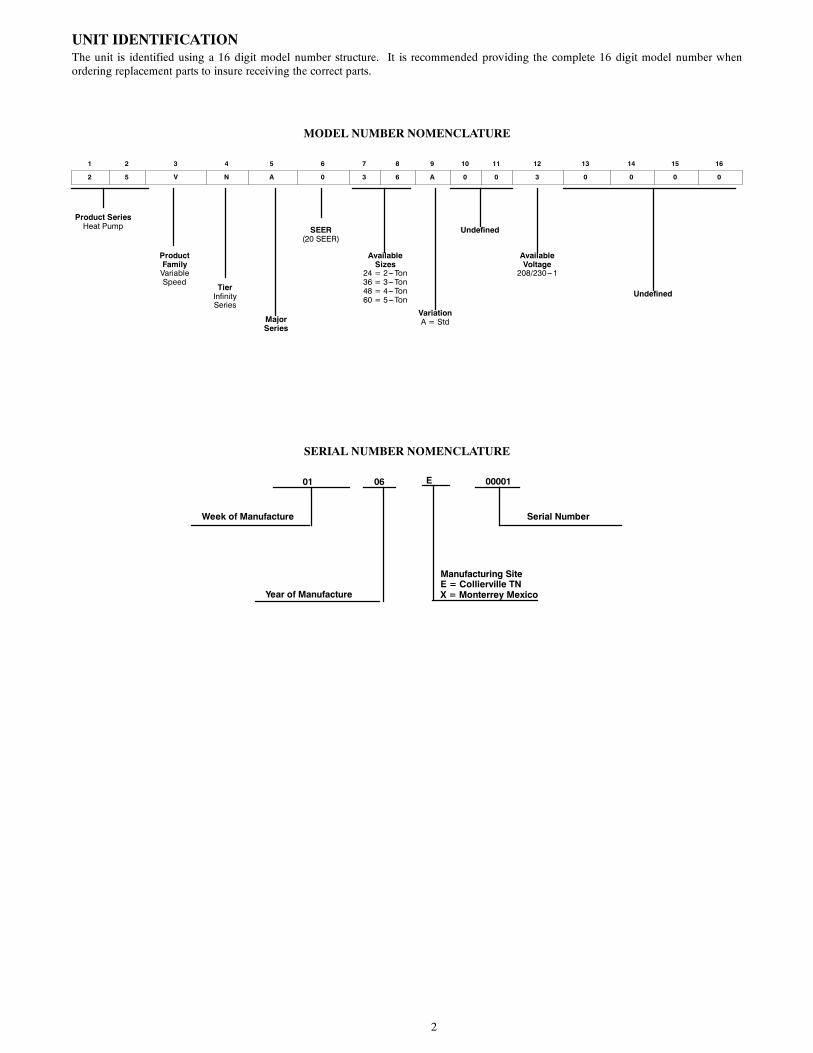
UNIT IDENTIFICATIONThe unit is identified using a 16 digit model number structure. It is recommended providing the complete 16 digit model number whenordering replacement parts to insure receiving the correct parts.
MODEL NUMBER NOMENCLATURE
1 2 3 4 5 6 7 8 9 10 11 12 13 14 15 16
2 5 V N A 0 3 6 A 0 0 3 0 0 0 0
Product SeriesHeat Pump
ProductFamilyVariableSpeed
TierInfinitySeries
MajorSeries
SEER(20 SEER)
AvailableSizes
24 = 2---Ton36 = 3---Ton48 = 4---Ton60 = 5---Ton
VariationA = Std
Undefined
AvailableVoltage
208/230---1
Undefined
SERIAL NUMBER NOMENCLATURE
01 06
Week of Manufacture
Year of Manufacture
00001
Serial Number
E
Manufacturing SiteE = Collierville TNX = Monterrey Mexico
3
SAFETY CONSIDERATIONSInstallation, service, and repair of these units should be attemptedonly by trained service technicians familiar with standard serviceinstruction and training material.
All equipment should be installed in accordance with acceptedpractices and unit Installation Instructions, and in compliance withall national and local codes. Power should be turned off whenservicing or repairing electrical components. Extreme cautionshould be observed when troubleshooting electrical componentswith power on. Observe all warning notices posted on equipmentand in instructions or manuals.
! WARNINGELECTRICAL SHOCK HAZARD
Failure to follow this warning could result in personalinjury or death.
Before installing, modifying, or servicing system, mainelectrical disconnect switch must be in the OFF position.There may be more than 1 disconnect switch. Lock out andtag switch with a suitable warning label.
! WARNINGELECTRICAL HAZARD -- HIGH VOLTAGE!
Failure to follow this warning could result in personal injuryor death.
Electrical components may hold charge. DO NOT removecontrol box cover for 2 minutes after power has beenremoved from unit.
PRIOR TO TOUCHING ELECTRICAL COMPONENTS:
Verify less than 20 vdc voltage at inverter connections shownon inverter cover.
CUT HAZARD
Failure to follow this caution may result in personal injury.
Sheet metal parts may have sharp edges or burrs. Use care andwear appropriate protective clothing and gloves whenhandling parts.
CAUTION!
UNIT OPERATION AND SAFETY HAZARD
Failure to follow this warning could result in personalinjury or equipment damage.
Puronr (R--410A) systems operate at higher pressures thanstandard R--22 systems. Do not use R--22 service equipmentor components on Puronr equipment. Ensure serviceequipment is rated for Puronr.
! WARNING
Refrigeration systems contain refrigerant under pressure. Extremecaution should be observed when handling refrigerants. Wearsafety glasses and gloves to prevent personal injury. During normalsystem operations, some components are hot and can cause burns.Rotating fan blades can cause personal injury. Appropriate safetyconsiderations are posted throughout this manual where potentiallydangerous techniques are addressed.
If you do not understand any of the warnings, contact yourproduct distributor for better interpretation of the warnings.
GENERAL INFORMATIONThe 25VNA Greenspeed Intelligence heat pump features a newoutdoor cabinet design that uses a four sided coil design tominimize the unit foot print and provide the best heat exchangetaking full advantage of the latest variable speed technology. Theheart of the system is the Copeland variable speed compressorpowered through the use of the Emerson variable speed drive(VSD) inverter control. Through the use of Puron refrigerant ,ECMoutdoor fan, Emerson VSD and Copeland variable speedcompressor along with the new outdoor cabinet the unit achieves aSeasonal Energy Efficiency Ratio (SEER) up to 20.5 and up to 13Heating Seasonal Performance Factor (HSPF).
To ensure all of the above technology provides the ultimate incomfort it is combined with either the FE fan coil or VariableSpeed Gas furnace controlled with a two wire communicationInfinity User Interface (SYSTXCCUID01--V) or the Infinity ZoneUser Interface (SYSTXCCUIZ01--V). Ensuring achievement ofcomfort with the consciences of finger tip trouble shooting anddiagnostic capability.
4
ELECTRICAL
ELECTRICAL SHOCK HAZARD
Failure to follow this warning could result in personal injuryor death.
Exercise extreme caution when working on any electricalcomponents. Shut off all power to system prior totroubleshooting. Some troubleshooting techniques requirepower to remain on. In these instances, exercise extremecaution to avoid danger of electrical shock. ONLY TRAINEDSERVICE PERSONNEL SHOULD PERFORMELECTRICAL TROUBLESHOOTING.
! WARNING
Aluminum Wire
UNIT OPERATION AND SAFETY HAZARD
Failure to follow this caution may result in equipmentdamage or improper operation.
Aluminum wire may be used in the branch circuit (such asthe circuit between the main and unit disconnect), but onlycopper wire may be used between the unit disconnect and theunit.
CAUTION!
Whenever aluminum wire is used in branch circuit wiring with thisunit, adhere to the following recommendations.
Connections must be made in accordance with the NationalElectrical Code (NEC), using connectors approved for aluminumwire. The connectors must be UL approved (marked Al/Cu withthe UL symbol) for the application and wire size. The wire sizeselected must have a current capacity not less than that of thecopper wire specified, and must not create a voltage drop betweenservice panel and unit in excess of 2 of unit rated voltage. Toprepare wire before installing connector, all aluminum wire mustbe “brush--scratched” and coated with a corrosion inhibitor such asPentrox A. When it is suspected that connection will be exposed tomoisture, it is very important to cover entire connection completelyto prevent an electrochemical action that will cause connection tofail very quickly. Do not reduce effective size of wire, such ascutting off strands so that wire will fit a connector. Proper sizeconnectors should be used. Check all factory and field electricalconnections for tightness. This should also be done after unit hasreached operating temperatures, especially if aluminum conductorsare used.
ContactorThe contactor provides a means of applying power to unit usinglow voltage (24v) from transformer in order to power contactorcoil. Depending on unit model, you may encounter single-- ordouble--pole contactors. Exercise extreme caution whentroubleshooting as 1 side of line may be electrically energized. Thecontactor coil is powered by 24vac. If contactor does not operate:
1. With power off, check whether contacts are free to move.Check for severe burning or arcing on contact points.
2. With power off, use ohmmeter to check for continuity ofcoil. Disconnect leads before checking. A low resistancereading is normal. Do not look for a specific value, asdifferent part numbers will have different resistance values.
3. Reconnect leads and apply low--voltage power to contactorcoil. This may be done by leaving high--voltage power tooutdoor unit off and turning thermostat to cooling. Checkvoltage at coil with voltmeter. Reading should be between20v and 30v. Contactor should pull in if voltage is correctand coil is good. If contactor does not pull in, replacecontactor.
4. With high--voltage power off and contacts pulled in, checkfor continuity across contacts with ohmmeter. A very low or0 resistance should be read. Higher readings could indicateburned or pitted contacts which may cause future failures.
Parts Location
REVERSING VALVE
ACCUMULATOR
SUCTION TUBE
SUCTION THERMISTOR (OST)
SUCTION SERVICE VALVE
ACCUMULATOR TUBE
COMPRESSOR
PRESSURE TRANSDUCER (SPT)
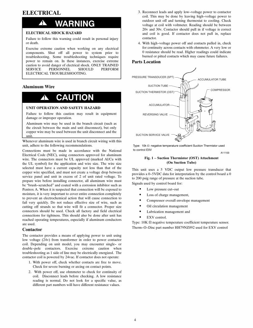
Type: 10k Ω negative temperature coefficient Suction Thermistor usedto control EXV
A11103
Fig. 1 – Suction Thermistor (OST) Attachment(On Suction Tube)
This unit uses a 5 VDC output low pressure transducer thatprovides a 0--5VDC data for interpretation by the control board a 0to 200 psig range of pressure at the suction tube.
Signals used by control board for:
S Low pressure cut--out
S Loss of charge management,
S Compressor overall envelope management
S Oil circulation management
S Lubrication management and
S EXV control.Type: 10K Ω negative temperature coefficient temperature sensor.
Therm--O--Disc part number HH79NZ092 used for EXV control
5
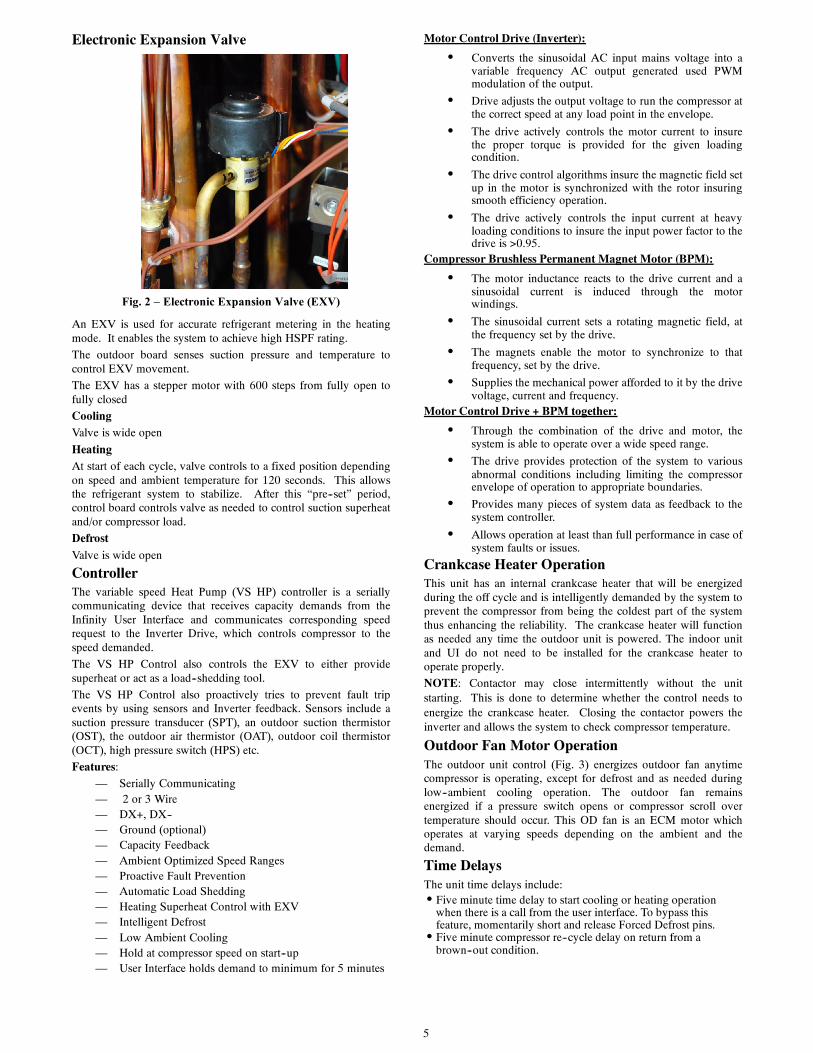
Electronic Expansion Valve
Fig. 2 – Electronic Expansion Valve (EXV)
An EXV is used for accurate refrigerant metering in the heatingmode. It enables the system to achieve high HSPF rating.
The outdoor board senses suction pressure and temperature tocontrol EXV movement.
The EXV has a stepper motor with 600 steps from fully open tofully closed
CoolingValve is wide open
HeatingAt start of each cycle, valve controls to a fixed position dependingon speed and ambient temperature for 120 seconds. This allowsthe refrigerant system to stabilize. After this “pre--set” period,control board controls valve as needed to control suction superheatand/or compressor load.
DefrostValve is wide open
ControllerThe variable speed Heat Pump (VS HP) controller is a seriallycommunicating device that receives capacity demands from theInfinity User Interface and communicates corresponding speedrequest to the Inverter Drive, which controls compressor to thespeed demanded.
The VS HP Control also controls the EXV to either providesuperheat or act as a load--shedding tool.
The VS HP Control also proactively tries to prevent fault tripevents by using sensors and Inverter feedback. Sensors include asuction pressure transducer (SPT), an outdoor suction thermistor(OST), the outdoor air thermistor (OAT), outdoor coil thermistor(OCT), high pressure switch (HPS) etc.
Features:
— Serially Communicating— 2 or 3 Wire— DX+, DX--— Ground (optional)— Capacity Feedback— Ambient Optimized Speed Ranges— Proactive Fault Prevention— Automatic Load Shedding— Heating Superheat Control with EXV— Intelligent Defrost— Low Ambient Cooling— Hold at compressor speed on start--up— User Interface holds demand to minimum for 5 minutes
Motor Control Drive (Inverter):
S Converts the sinusoidal AC input mains voltage into avariable frequency AC output generated used PWMmodulation of the output.
S Drive adjusts the output voltage to run the compressor atthe correct speed at any load point in the envelope.
S The drive actively controls the motor current to insurethe proper torque is provided for the given loadingcondition.
S The drive control algorithms insure the magnetic field setup in the motor is synchronized with the rotor insuringsmooth efficiency operation.
S The drive actively controls the input current at heavyloading conditions to insure the input power factor to thedrive is >0.95.
Compressor Brushless Permanent Magnet Motor (BPM):
S The motor inductance reacts to the drive current and asinusoidal current is induced through the motorwindings.
S The sinusoidal current sets a rotating magnetic field, atthe frequency set by the drive.
S The magnets enable the motor to synchronize to thatfrequency, set by the drive.
S Supplies the mechanical power afforded to it by the drivevoltage, current and frequency.
Motor Control Drive + BPM together:
S Through the combination of the drive and motor, thesystem is able to operate over a wide speed range.
S The drive provides protection of the system to variousabnormal conditions including limiting the compressorenvelope of operation to appropriate boundaries.
S Provides many pieces of system data as feedback to thesystem controller.
S Allows operation at least than full performance in case ofsystem faults or issues.
Crankcase Heater OperationThis unit has an internal crankcase heater that will be energizedduring the off cycle and is intelligently demanded by the system toprevent the compressor from being the coldest part of the systemthus enhancing the reliability. The crankcase heater will functionas needed any time the outdoor unit is powered. The indoor unitand UI do not need to be installed for the crankcase heater tooperate properly.
NOTE: Contactor may close intermittently without the unitstarting. This is done to determine whether the control needs toenergize the crankcase heater. Closing the contactor powers theinverter and allows the system to check compressor temperature.
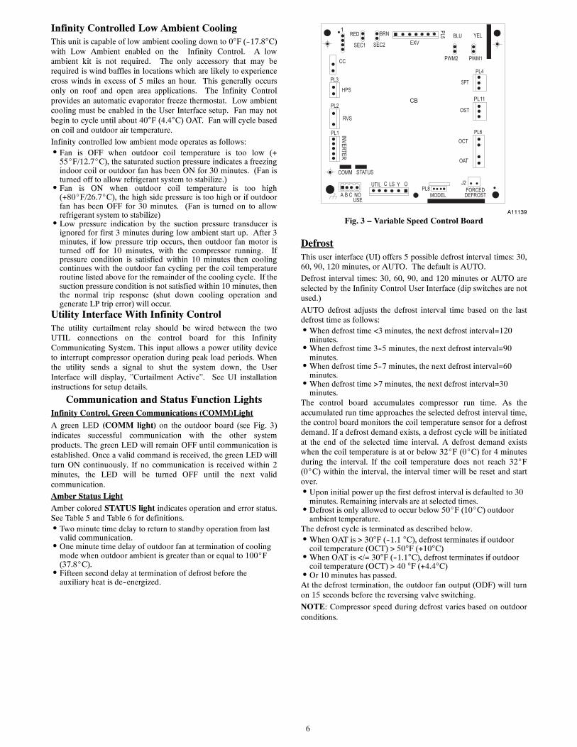
Outdoor Fan Motor OperationThe outdoor unit control (Fig. 3) energizes outdoor fan anytimecompressor is operating, except for defrost and as needed duringlow--ambient cooling operation. The outdoor fan remainsenergized if a pressure switch opens or compressor scroll overtemperature should occur. This OD fan is an ECM motor whichoperates at varying speeds depending on the ambient and thedemand.
Time DelaysThe unit time delays include:S Five minute time delay to start cooling or heating operation
when there is a call from the user interface. To bypass thisfeature, momentarily short and release Forced Defrost pins.S Five minute compressor re--cycle delay on return from a
brown--out condition.
6
Infinity Controlled Low Ambient CoolingThis unit is capable of low ambient cooling down to 0°F (--17.8°C)with Low Ambient enabled on the Infinity Control. A lowambient kit is not required. The only accessory that may berequired is wind baffles in locations which are likely to experiencecross winds in excess of 5 miles an hour. This generally occursonly on roof and open area applications. The Infinity Controlprovides an automatic evaporator freeze thermostat. Low ambientcooling must be enabled in the User Interface setup. Fan may notbegin to cycle until about 40°F (4.4°C) OAT. Fan will cycle basedon coil and outdoor air temperature.
Infinity controlled low ambient mode operates as follows:S Fan is OFF when outdoor coil temperature is too low (+
55_F/12.7_C), the saturated suction pressure indicates a freezingindoor coil or outdoor fan has been ON for 30 minutes. (Fan isturned off to allow refrigerant system to stabilize.)S Fan is ON when outdoor coil temperature is too high
(+80_F/26.7_C), the high side pressure is too high or if outdoorfan has been OFF for 30 minutes. (Fan is turned on to allowrefrigerant system to stabilize)S Low pressure indication by the suction pressure transducer is
ignored for first 3 minutes during low ambient start up. After 3minutes, if low pressure trip occurs, then outdoor fan motor isturned off for 10 minutes, with the compressor running. Ifpressure condition is satisfied within 10 minutes then coolingcontinues with the outdoor fan cycling per the coil temperatureroutine listed above for the remainder of the cooling cycle. If thesuction pressure condition is not satisfied within 10 minutes, thenthe normal trip response (shut down cooling operation andgenerate LP trip error) will occur.
Utility Interface With Infinity ControlThe utility curtailment relay should be wired between the twoUTIL connections on the control board for this InfinityCommunicating System. This input allows a power utility deviceto interrupt compressor operation during peak load periods. Whenthe utility sends a signal to shut the system down, the UserInterface will display, ”Curtailment Active”. See UI installationinstructions for setup details.
Communication and Status Function LightsInfinity Control, Green Communications (COMM)Light
A green LED (COMM light) on the outdoor board (see Fig. 3)indicates successful communication with the other systemproducts. The green LED will remain OFF until communication isestablished. Once a valid command is received, the green LED willturn ON continuously. If no communication is received within 2minutes, the LED will be turned OFF until the next validcommunication.
Amber Status LightAmber colored STATUS light indicates operation and error status.See Table 5 and Table 6 for definitions.S Two minute time delay to return to standby operation from last
valid communication.S One minute time delay of outdoor fan at termination of cooling
mode when outdoor ambient is greater than or equal to 100_F(37.8_C).S Fifteen second delay at termination of defrost before the
auxiliary heat is de--energized.
CB
MODEL PL8 FORCED
DEFROST
J2
1 BRNRED
SEC1 SEC2
PWM2 PWM1
INVERTER
PL1
PL2
RVS
CC
PL11
PL4
PL6OCT
OAT
SPT
OST
A B C NOUSE
UTIL LS YC O
COMM STATUS
YELBLUEXV
PL5
PL3
HPS
A11139
Fig. 3 – Variable Speed Control Board
DefrostThis user interface (UI) offers 5 possible defrost interval times: 30,60, 90, 120 minutes, or AUTO. The default is AUTO.
Defrost interval times: 30, 60, 90, and 120 minutes or AUTO areselected by the Infinity Control User Interface (dip switches are notused.)
AUTO defrost adjusts the defrost interval time based on the lastdefrost time as follows:S When defrost time <3 minutes, the next defrost interval=120
minutes.S When defrost time 3--5 minutes, the next defrost interval=90
minutes.S When defrost time 5--7 minutes, the next defrost interval=60
minutes.S When defrost time >7 minutes, the next defrost interval=30
minutes.The control board accumulates compressor run time. As theaccumulated run time approaches the selected defrost interval time,the control board monitors the coil temperature sensor for a defrostdemand. If a defrost demand exists, a defrost cycle will be initiatedat the end of the selected time interval. A defrost demand existswhen the coil temperature is at or below 32_F (0_C) for 4 minutesduring the interval. If the coil temperature does not reach 32_F(0_C) within the interval, the interval timer will be reset and startover.S Upon initial power up the first defrost interval is defaulted to 30
minutes. Remaining intervals are at selected times.S Defrost is only allowed to occur below 50_F (10_C) outdoor
ambient temperature.The defrost cycle is terminated as described below.S When OAT is > 30°F (--1.1 °C), defrost terminates if outdoor
coil temperature (OCT) > 50°F (+10°C)S When OAT is </= 30°F (--1.1°C), defrost terminates if outdoor
coil temperature (OCT) > 40 °F (+4.4°C)S Or 10 minutes has passed.At the defrost termination, the outdoor fan output (ODF) will turnon 15 seconds before the reversing valve switching.
NOTE: Compressor speed during defrost varies based on outdoorconditions.
7
SCHEMATIC DIAGRAM (LADDER FORM)CONNECTION DIAGRAMCOMPONENT ARRANGEMENT
TRANCONT
CONTROL
BOARD
24 001 5.1 11
MODEL MODELPLUG
HK70EZSIZE
MODEL PLUG CHART
1 - 4 (R1) 2 - 3 (R2)PIN RESISTANCE (K )
36 002 5.1 1848 003 5.1 2460 004 5.1 33
INVERTER
CB
CONT
208/230 1ØPOWERSUPPLY
EQUIP GND
L1
L2
RED/WHT
BRN/YEL
MODEL
TRAN 24V
230V 208V COM
RED
BRN
BLK
YEL11 21
23 23
C C
PL8 FORCEDDEFROST
J2
1 BRNRED
SEC1 SEC2
PWM2 PWM1
INVERTER
PL1
RVSORG
ORGPL2
RVS
REDBLK
WHTGRN
CC
PL11
OCT
OAT
PL4
BRNBRN
BLK
SPTRED
BLK
PL6
OSTBLK
OCT
OAT
WHTSPT
OST
+
-
BLK
BLK
A B C NOUSE
UTIL LS YC O
COMM STATUS
BLU
YEL
OFM
GRN/YEL
YELBLU
EXV
EXV
PL5
BLU/PNKBLU/PNK
HPS
PL3
HPS
YEL
CHOKE
CHOKE
COMP
INVERTER
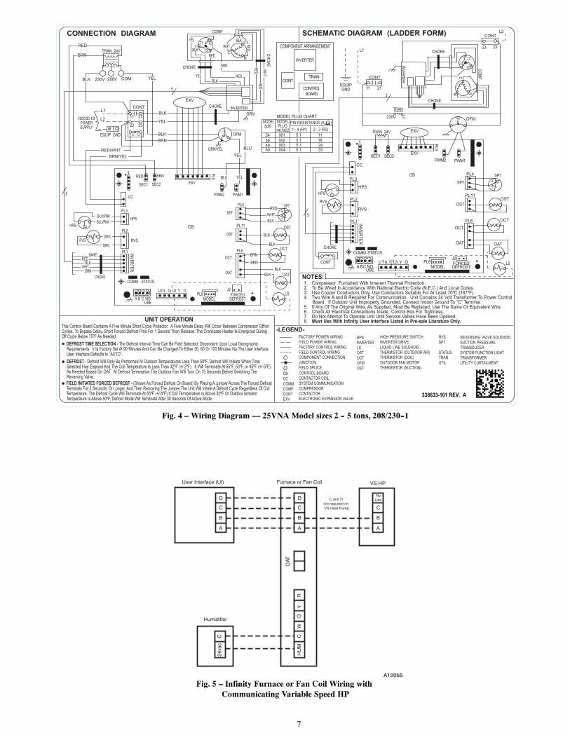
1. Compressor Furnished With Inherent Thermal Protection.2. To Be Wired In Accordance With National Electric Code (N.E.C.) And Local Codes.3. Use Copper Conductors Only. Use Conductors Suitable For At Least 70ºC (167ºF).4. Two Wire A and B Required For Communication. Unit Contains 24 Volt Transformer To Power Control Board. If Outdoor Unit Improperly Grounded, Connect Indoor Ground To “C” Terminal.5. If Any Of The Original Wire, As Supplied, Must Be Replaced, Use The Same Or Equivalent Wire.6. Check All Electrical Connections Inside Control Box For Tightness.7. Do Not Attempt To Operate Unit Until Service Valves Have Been Opened.8. Must Use With Infinity User Interface Listed In Pre-sale Literature Only.
FIELD INITIATED FORCED DEFROST - (Shown As Forced Defrost On Board) By Placing A Jumper Across The Forced DefrostTerminals For 5 Seconds, Or Longer, And Then Removing The Jumper The Unit Will Initate A Defrost Cycle Regardless Of Coil Temperature. The Defrost Cycle Will Terminate At 65ºF (+/-5ºF) If Coil Termperature Is Above 32ºF Or Outdoor Ambient Temperature Is Above 50ºF, Defrost Mode Will Terminate After 30 Seconds Of Active Mode.
This Control Board Contains A Five Minute Short Cycle Protector. A Five Minute Delay Will Occur Between Compressor Off/on Cycles. To Bypass Delay, Short Forced Defrost Pins For 1 Second Then Release. The Crankcase Heater Is Energized During Off Cycle Below 75ºF As Needed.
DEFROST TIME SELECTION - The Defrost Interval Time Can Be Field Selected, Dependent Upon Local Georgraphic Requirements. It Is Factory Set At 90 Minutes And Can Be Changed To Either 30, 60 Or 120 Minutes Via The User Interface. User Interface Defaults to “AUTO”.DEFROST - Defrost Will Only Be Performed At Outdoor Temperatures Less Than 50ºF. Defrost Will Initiate When Time Selected Has Elapsed And The Coil Temperature Is Less Than 32ºF (+/-2ºF). It Will Terminate At 65ºF, 50ºF, or 45ºF (+/-5ºF), As Needed Based On OAT. At Defrost Termination The Outdoor Fan Will Turn On 15 Seconds Before Switching TheReversing Valve..
NOTES:
UNIT OPERATION-LEGEND-
FACTORY POWER WIRINGFIELD POWER WIRINGFACTORY CONTROL WIRINGFIELD CONTROL WIRINGCOMPONENT CONNECTIONJUNCTIONFIELD SPLICE
LS
CB
FORCEDDEFROST
OCT
OAT
MODEL
HPS
A BC NOUSE
SPT
J2PL8
RVS
1
SEC1 SEC2EXV
PL5
PWM2 PWM1
OST
+
-
CONT
EXVTRAN 24V
OFM
11 21
CONT
TRAN
C230V
23 23
CONTL2
L1
EQUIPGND
COMM STATUS
PL2
RVS
CC
PL3
HPS
PL11
PL4
PL6
OCT
OAT
SPT
OST
INV
ER
TE
R
PL1
CHOKE
UTIL LS YC O
BLK
LS
BLK
BRN
GRN
BARE
338633-101 REV. A
HPSINVERTERLSOATOCTOFMOST
HIGH PRESSURE SWITCHINVERTER DRIVELIQUID LINE SOLENOIDTHERMISTOR (OUTDOOR AIR)THERMISTOR (COIL)OUTDOOR FAN MOTORTHERMISTOR (SUCTION)
CBCCCOMMCOMPCONTEXV
CONTROL BOARDCONTACTOR COILSYSTEM COMMUNICATIONCOMPRESSORCONTACTORELECTRONIC EXPANSION VALVE
RVSSPT
STATUSTRANUTIL
REVERSING VALVE SOLENOIDSUCTION PRESSURETRANSDUCERSYSTEM FUNCTION LIGHTTRANSFORMERUTILITY CURTAILMENT
CH
OK
E
5
5
55
T2T1T3
GRNCHOKE
REDBLK
YEL
RED
YEL
BLKS
CM
WHT
REDBLK
WHTBLK RED
COMP
INVERTER
T2T1T3
CHOKE
S
CM
CHOKE
Fig. 4 – Wiring Diagram — 25VNA Model sizes 2 -- 5 tons, 208/230--1
D
C
B
A
User Interface (UI)
D
C
B
A
NoUse
C
B
A
VS HP
OAT
RY
OW
CH
UM
C
Humidifier
24va
c
C and D
not required on
VS Heat Pump
Furnace or Fan Coil
A12055
Fig. 5 – Infinity Furnace or Fan Coil Wiring withCommunicating Variable Speed HP
8
REFRIGERANT PIPING LENGTH LIMITATIONSMaximum Line Lengths:The maximum allowable total equivalent length for heat pumps varies depending on the vertical separation. See the tables below forallowable lengths depending on whether the outdoor unit is on the same level, above or below the outdoor unit.
MAXIMUM LINE LENGTHS FOR HEAT PUMP APPLICATIONS
MAXIMUM ACTUAL LENGTHft (m)
MAXIMUM EQUIVALENT LENGTHft (m)
MAXIMUM VERTICAL SEPARA-TION ft (m)
Units on equal level 200 (61) 250 (76.2) N/A
Outdoor unit ABOVEindoor unit 200 (61) 250 (76.2) 200 (61)
Outdoor unit BELOWindoor unit See Table ’Maximum Total Equivalent Length: Outdoor Unit BELOW Indoor Unit’
Total equivalent length accounts for losses due to elbows or fitting. See the Long Line Guideline for details.
Maximum Total Equivalent Length -- Outdoor Unit BELOW Indoor Unit
SizeLiquid LineDiameterw/ TXV
HP with Puronr Refrigerant --- Maximum Total Equivalent LengthVertical Separation ft (m) Outdoor unit BELOW indoor unit;
0---20(0 --- 6.1)
21---30(6.4 --- 9.1)
31---40(9.4 --- 12.2)
41---50(12.5 --- 15.2)
51---60(15.5 --- 18.3)
61---70(18.6 --- 21.3)
71---80(21.6 --- 24.4)
024HP withPuron
3/8 250* 250* 250* 250* 250* 250* 250*
036HP withPuron
3//8 250* 250* 250* 250* 250* 250* 250*
048HP withPuron
3/8 250* 250* 250* 250* 230 160 --- ---
060HP withPuron
3/8 250* 225* 190 150 110 --- --- --- ---
* Maximum actual length not to exceed 200 ft (61 m) Total equivalent length accounts for losses due to elbows or fitting. See the Long Line Guideline for details.--- --- = outside acceptable range
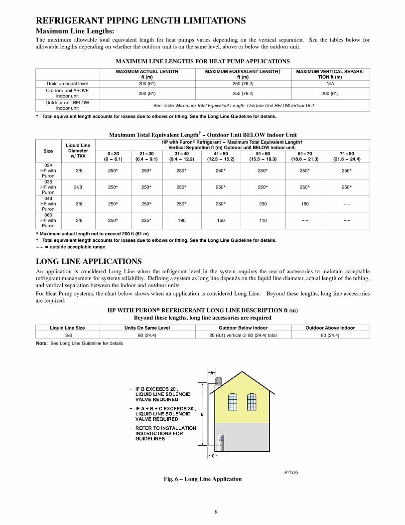
LONG LINE APPLICATIONSAn application is considered Long Line when the refrigerant level in the system requires the use of accessories to maintain acceptablerefrigerant management for systems reliability. Defining a system as long line depends on the liquid line diameter, actual length of the tubing,and vertical separation between the indoor and outdoor units.
For Heat Pump systems, the chart below shows when an application is considered Long Line. Beyond these lengths, long line accessoriesare required:
HP WITH PURONr REFRIGERANT LONG LINE DESCRIPTION ft (m)Beyond these lengths, long line accessories are required
Liquid Line Size Units On Same Level Outdoor Below Indoor Outdoor Above Indoor
3/8 80 (24.4) 20 (6.1) vertical or 80 (24.4) total 80 (24.4)
Note: See Long Line Guideline for details
A11265
Fig. 6 – Long Line Application
9
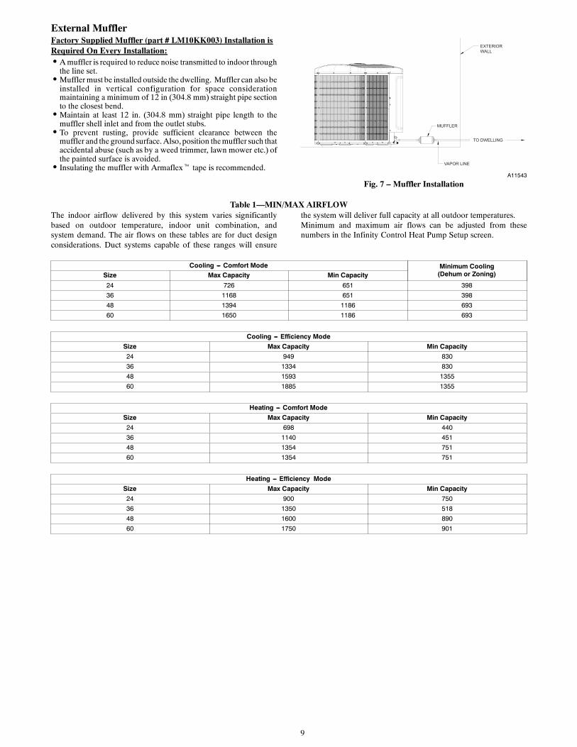
External MufflerFactory Supplied Muffler (part # LM10KK003) Installation isRequired On Every Installation:S A muffler is required to reduce noise transmitted to indoor through
the line set.S Muffler must be installed outside the dwelling. Muffler can also be
installed in vertical configuration for space considerationmaintaining a minimum of 12 in (304.8 mm) straight pipe sectionto the closest bend.S Maintain at least 12 in. (304.8 mm) straight pipe length to the
muffler shell inlet and from the outlet stubs.S To prevent rusting, provide sufficient clearance between the
muffler and the ground surface. Also, position themuffler such thataccidental abuse (such as by a weed trimmer, lawn mower etc.) ofthe painted surface is avoided.S Insulating the muffler with Armaflext tape is recommended.
EXTERIOR
WALL
VAPOR LINE
MUFFLER
TO DWELLING
A11543
Fig. 7 – Muffler Installation
Table 1—MIN/MAX AIRFLOWThe indoor airflow delivered by this system varies significantlybased on outdoor temperature, indoor unit combination, andsystem demand. The air flows on these tables are for duct designconsiderations. Duct systems capable of these ranges will ensure
the system will deliver full capacity at all outdoor temperatures.Minimum and maximum air flows can be adjusted from thesenumbers in the Infinity Control Heat Pump Setup screen.
Cooling --- Comfort Mode Minimum Cooling(Dehum or Zoning)Size Max Capacity Min Capacity
24 726 651 398
36 1168 651 398
48 1394 1186 693
60 1650 1186 693
Cooling --- Efficiency Mode
Size Max Capacity Min Capacity
24 949 830
36 1334 830
48 1593 1355
60 1885 1355
Heating --- Comfort Mode
Size Max Capacity Min Capacity
24 698 440
36 1140 451
48 1354 751
60 1354 751
Heating --- Efficiency Mode
Size Max Capacity Min Capacity
24 900 750
36 1350 518
48 1600 890
60 1750 901
10
TROUBLESHOOTINGSystems Communication FailureIf communication with the Infinity control is lost with the UserInterface (UI), the control will flash the appropriate fault code (seeTable 5 and Table 6). Check the wiring to the User Interface andthe indoor and outdoor units and power.
Model PlugEach control board contains a model plug. The correct model plugmust be installed for the system to operate properly (see Table 2).
Table 2—Model Plug Information
MODELNUMBER
MODEL PLUGNUMBER
PIN RESISTANCE(K---ohms)
Pins 1---4 Pins 2---3
25VNA024 HK70EZ001 5.1K 11K
25VNA036 HK70EZ002 5.1K 18K
25VNA048 HK70EZ003 5.1K 24K
25VNA060 HK70EZ004 5.1K 33K
The model plug is used to identify the type and size of unit to thecontrol.
On new units, the model and serial numbers are input into theboard’s memory at the factory. If a model plug is lost or missing atinitial installation, the unit will operate according to theinformation input at the factory and the appropriate error code willflash temporarily. An RCD replacement board contains no modeland serial information. If the factory control board fails, the modelplug must be transferred from the original board to the replacementboard for the unit to operate.
NOTE: The model plug takes priority over factory modelinformation input at the factory. If the model plug is removed afterinitial power up, the unit will operate according to the last validmodel plug installed, and flash the appropriate fault codetemporarily.
Pressure Switch ProtectionThe outdoor unit is equipped with high pressure switch. If thecontrol senses the opening of a high pressure switch, it willrespond as follows:
1. De--energize the contactor.
2. Keep the outdoor fan operating for 15 minutes.
3. Display the appropriate fault code (see Table 5 and Table 6).
4. After a 15 minute delay, if there is a call for cooling or heat-ing and HPS is reset, the contactor is energized.
5. If HPS has not closed after a 15 minute delay, the outdoorfan is turned off. If the open switch closes anytime after the15 minute delay, then resume operation with a call for cool-ing or heating at a temporary reduced capacity.
6. If HPS trips 3 consecutive cycles, the unit operation islocked out for 4 hours.
7. In the event of a high--pressure switch trip or high--pressurelockout, check the refrigerant charge, outdoor fan operation,and outdoor coil (in cooling) for airflow restrictions, or in-door airflow in heating.
8. In the event of a low--pressure trip or low--pressure lockout,check the refrigerant charge and indoor airflow (cooling)and outdoor fan operation and outdoor coil in heating.
Control FaultIf the outdoor unit control board has failed, the control will flashthe appropriate fault code. The control board should be replaced.
If the sensors are out of range, the control will flash the appropriatefault code.
The thermistor comparisons are not performed during low ambientcooling or defrost operation.
Failed Thermistor Default OperationFactory defaults have been provided in the event of failure ofoutdoor air thermistor (OAT) and/or outdoor coil thermistor(OCT).
If the OAT sensor should fail, low ambient cooling will not beallowed and the one--minute outdoor fan off delay will not occur.Defrost will be initiated based on coil temperature and time.
If the OCT sensor should fail, low ambient cooling will not beallowed. Defrost will occur at each time interval during heatingoperation, but will terminate after 5 minutes.
If there is a thermistor out--of--range error, defrost will occur ateach time interval during heating operation, but will terminate after5 minutes.
Count the number of short and long flashes to determine theappropriate flash code.
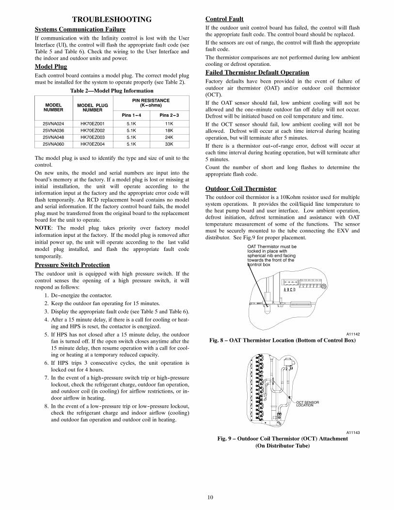
Outdoor Coil ThermistorThe outdoor coil thermistor is a 10Kohm resistor used for multiplesystem operations. It provides the coil/liquid line temperature tothe heat pump board and user interface. Low ambient operation,defrost initiation, defrost termination and assistance with OATtemperature measurement of some of the functions. The sensormust be securely mounted to the tube connecting the EXV anddistributor. See Fig.9 for proper placement.
OAT Thermistor must belocked in place withspherical nib end facingtowards the front of thecontrol box
A11142
Fig. 8 – OAT Thermistor Location (Bottom of Control Box)
OCT SENSORLOCATION
A11143
Fig. 9 – Outdoor Coil Thermistor (OCT) Attachment(On Distributor Tube)
11
REVERSING VALVE
ACCUMULATOR
SUCTION TUBE
SUCTION THERMISTOR (OST)
SUCTION SERVICE VALVE
ACCUMULATOR TUBE
COMPRESSOR
PRESSURE TRANSDUCER (SPT)
A11103
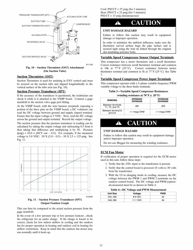
Fig. 10 – Suction Thermistor (OST) Attachment(On Suction Tube)
Suction Thermistor (OST)Suction Thermistor is used for assisting in EXV control and mustbe secured on the suction tube and aligned longitudinally to thevertical surface of the tube axis (see Fig. 10).
Suction Pressure Transducer (SPT)If the accuracy of the transducer is questioned, the technician cancheck it while it is attached to the VSHP board. Connect a gagemanifold to the suction valve gage port fitting.
At the VSHP board, with the wire harness receptacle exposing aportion of the three pins on the VSHP board, a DC voltmeter canread the DC voltage between ground and supply (input) terminal.Ensure that the input voltage is 5 VDC. Next, read the DC voltageacross the ground and output terminal. Record the output voltage.
The suction pressure that the pressure transducer is reading can becalculated by taking the output voltage and subtracting 0.5 from itthen taking that difference and multiplying it by 50. Pressure(psig) = 50.0 x (DCV out -- 0.5). For example, if the measuredvoltage is 3.0 VDC: 50 X (3.0 -- 0.5) -- 50 X 2.5 = 125 psig. SeeFig. 11.
0
1
2
3
4
5
6
0 25 50 75 100 125 150 175 200 225
Out
put V
olta
ge (V
)
Pressure - Sealed Gauge (psi)
A12035
Fig. 11 – Suction Pressure Transducer (SPT)Output Funtion Graph
This can then be compared to the actual suction pressure from thegage manifold.
In the event of a low pressure trip or low pressure lockout , checkthe refrigerant for an under charge. If the charge is found to becorrect, check for low indoor airflow in cooling and the outdoorfan for proper operation in heating and outdoor coil in heating forairflow restrictions. Keep in mind that the outdoor fan motor mayrun normally until it heats up.
Cool: PSUCT < 55 psig (for 3 minutes)Heat: PSUCT < 23 psig (for 3 minutes)PSUCT < 13 psig (instantaneous)
CAUTION!
UNIT DAMAGE HAZARD
Failure to follow this caution may result in equipmentdamage or improper operation.
In order to minimize the ambient influence, make sure thethermistor curved surface hugs the pipe surface and issecured tight using the wire tie fished through the originalslot insulating polymer body.
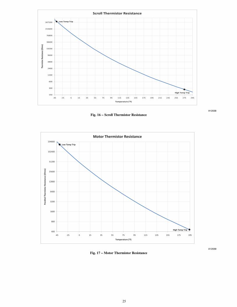
Variable Speed Compressor Sensor Output TerminalsThis compressor has a motor thermistor and a scroll thermistor.Correct resistance between scroll thermistor terminal and commonis 10k at 77_F (25_C). Correct resistance between motorthermistor terminal and common is 5k at 77_F (25_C). See Table7.
Variable Speed Compressor Power Input TerminalsThis compressor operates with a 3--phase variable frequency PWMvariable voltage to the three fusite terminals.
Table 3—Variable Speed Compressor Resistances(winding resistance at 70_F 20_F)
WINDING 25VNA02425VNA036
25VNA04825VNA060
Between terminalsT1, T2, and T3 .681 .203
Between terminal &ground >1 mega OHM >1 mega OHM
UNIT DAMAGE HAZARD
Failure to follow this caution may result in equipment damageand/or improper operation.
Do not use Meggar for measuring the winding resistance.
CAUTION!
ECM Fan MotorIf verification of proper operation is required for the ECM motorused in this unit, follow these steps:
1. Verify that the 230v input to the transformer is present.
2. Verify that the control board is powered 18 volts to 30 voltsfrom the transformer.
3. With the UI in charging mode in cooling, measure the DCvoltage between the PWM 1 and PWM 2 terminals on theoutdoor control board. The DC voltage and PWM (option-al) measured must be as shown in Table 4.
Table 4—DC Voltage and PWM MeasurementUnit Size Voltage PWM
024, 036 8.9 VDC 52
048, 060 11.1 VDC 84
12
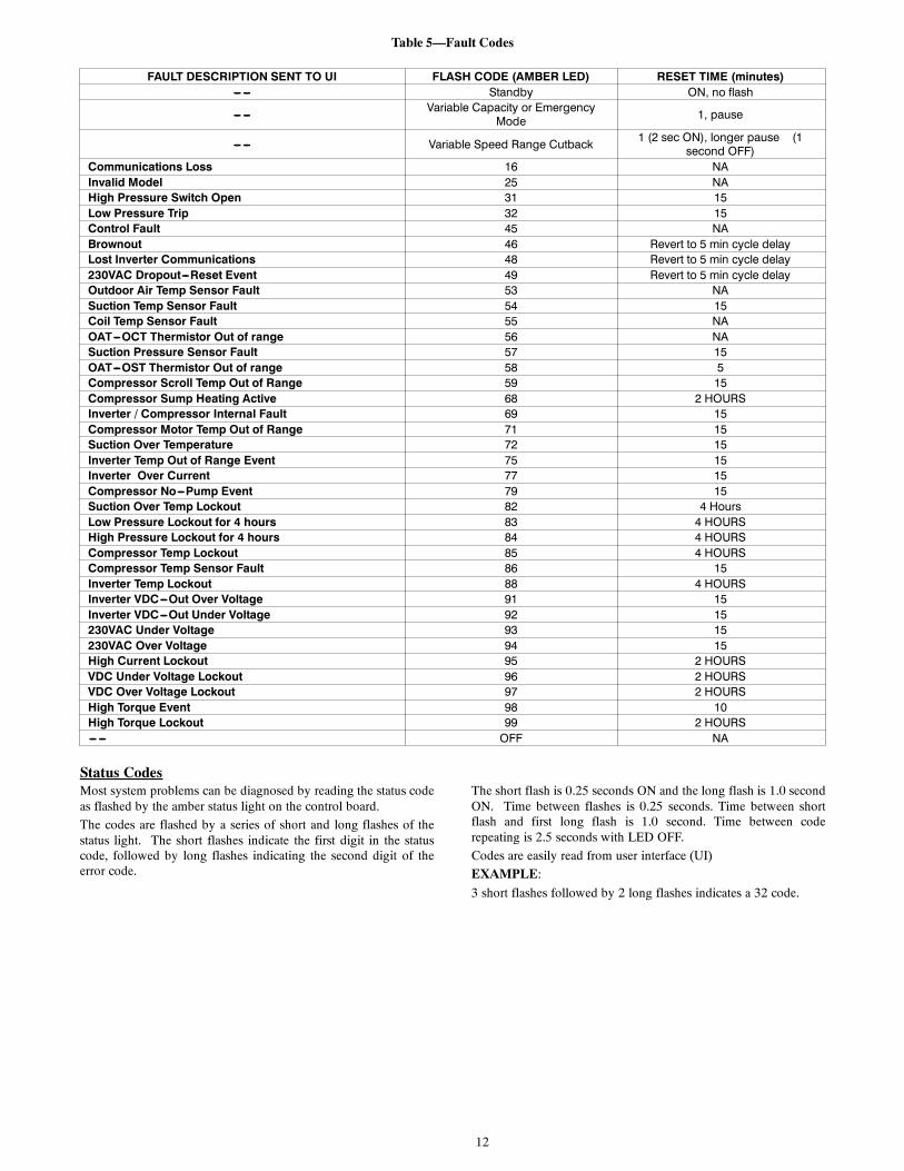
Table 5—Fault Codes
FAULT DESCRIPTION SENT TO UI FLASH CODE (AMBER LED) RESET TIME (minutes)--- --- Standby ON, no flash
--- ---Variable Capacity or Emergency
Mode 1, pause
--- --- Variable Speed Range Cutback1 (2 sec ON), longer pause (1
second OFF)Communications Loss 16 NAInvalid Model 25 NAHigh Pressure Switch Open 31 15Low Pressure Trip 32 15Control Fault 45 NABrownout 46 Revert to 5 min cycle delayLost Inverter Communications 48 Revert to 5 min cycle delay230VAC Dropout---Reset Event 49 Revert to 5 min cycle delayOutdoor Air Temp Sensor Fault 53 NASuction Temp Sensor Fault 54 15Coil Temp Sensor Fault 55 NAOAT---OCT Thermistor Out of range 56 NASuction Pressure Sensor Fault 57 15OAT---OST Thermistor Out of range 58 5Compressor Scroll Temp Out of Range 59 15Compressor Sump Heating Active 68 2 HOURSInverter / Compressor Internal Fault 69 15Compressor Motor Temp Out of Range 71 15Suction Over Temperature 72 15Inverter Temp Out of Range Event 75 15Inverter Over Current 77 15Compressor No---Pump Event 79 15Suction Over Temp Lockout 82 4 HoursLow Pressure Lockout for 4 hours 83 4 HOURSHigh Pressure Lockout for 4 hours 84 4 HOURSCompressor Temp Lockout 85 4 HOURSCompressor Temp Sensor Fault 86 15Inverter Temp Lockout 88 4 HOURSInverter VDC---Out Over Voltage 91 15Inverter VDC---Out Under Voltage 92 15230VAC Under Voltage 93 15230VAC Over Voltage 94 15High Current Lockout 95 2 HOURSVDC Under Voltage Lockout 96 2 HOURSVDC Over Voltage Lockout 97 2 HOURSHigh Torque Event 98 10High Torque Lockout 99 2 HOURS--- --- OFF NA
Status CodesMost system problems can be diagnosed by reading the status codeas flashed by the amber status light on the control board.
The codes are flashed by a series of short and long flashes of thestatus light. The short flashes indicate the first digit in the statuscode, followed by long flashes indicating the second digit of theerror code.
The short flash is 0.25 seconds ON and the long flash is 1.0 secondON. Time between flashes is 0.25 seconds. Time between shortflash and first long flash is 1.0 second. Time between coderepeating is 2.5 seconds with LED OFF.
Codes are easily read from user interface (UI)
EXAMPLE:
3 short flashes followed by 2 long flashes indicates a 32 code.
13
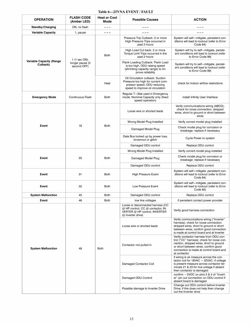
Table 6—25VNA EVENT / FAULT
OPERATIONFLASH CODE(Amber LED)
Heat or CoolMode Possible Causes ACTION
Standby/Charging ON, no flash --- --- --- --- --- --- --- --- ---
Variable Capacity 1, pause --- --- --- --- --- --- --- --- ---
Variable Capacity (RangeCutback)
1 (1 sec ON),longer pause (2second OFF)
Both
Pressure Trip Cutback: 2 or moreHigh Pressure Trips occurred in
past 2 hours
System will self ---mitigate, persistent con-ditions will lead to lockout (refer to Error
Code 84)
High Load Cut back: 2 or moreTorque Limit Trips occurred in the
past 2 hours
System will try to self ---mitigate, persist-ent conditions will lead to lockout (refer
to Error Code 99)
Flank Loading Cutback: Flank Loadis too high, ODU raising speed(shrinking capacity range) to im-
prove reliability
System will try to self ---mitigate, persist-ent conditions will lead to lockout (refer
to Error Code 99)
Heat
Oil Circulation cutback: SuctionPressure too high for current com-pressor speed; ODU reducingspeed to improve oil circulation
check for Indoor airflow restrictions
Emergency Mode Continuous Flash BothRegular T---Stat used in Emergencymode: Nominal Capacity only (fixed
speed operation)install Infinity User Interface
Event 16 Both
Loose wire or shorted leads
Verify communications wiring (ABCD);check for loose connection, stripped
wires, short to ground or short betweenwires
Wrong Model Plug Installed Verify correct model plug installed
Damaged Model PlugCheck model plug for corrosion orbreakage; replace if necessary
Data Bus locked up by power loss,brownout or glitch Cycle Power to system
Damaged ODU control Replace ODU control
Event 25 Both
Wrong Model Plug Installed Verify correct model plug installed
Damaged Model PlugCheck model plug for corrosion orbreakage; replace if necessary
Damaged ODU control Replace ODU control
Event 31 Both High Pressure EventSystem will self ---mitigate, persistent con-ditions will lead to lockout (refer to Error
Code 84)
Event 32 Both Low Pressure EventSystem will self ---mitigate, persistent con-ditions will lead to lockout (refer to Error
Code 83)
System Malfunction 45 Both Damaged ODU control Replace ODU control
Event 46 Both low line voltages if persistent contact power provider
System Malfunction 48 Both
Loose or disconnected harness (CC@ HP control, CC @ contactor, IN-VERTER @ HP control, INVERTER@ inverter drive)
Verify good harness connection
Loose wire or shorted leads
Verify communications wiring (”Inverter”harness); check for loose connection,stripped wires, short to ground or shortbetween wires; confirm good connectionis made at control board and at Inverter
Contactor not pulled in
Verify contactor harness from ODU con-trol (”CC” harness); check for loose con-nection, stripped wires, short to groundor short between wires; confirm goodconnection is made at control board andat contactor
Damaged Contactor Coil
if wiring is ok measure across the con-tactor coil for 18VAC --- 32VAC; if voltageis present measure across contactor ter-minals 21 & 23 for line voltage if absentthen contactor is damaged
Damaged ODU Controlconfirm ~5VDC on pins 3 & 4 of ”Invert-er” pin out connection on ODU control ifabsent board is damaged
Possible damage to Inverter DriveChange out ODU control before InverterDrive; if this does not help then changeout the Inverter drive
14
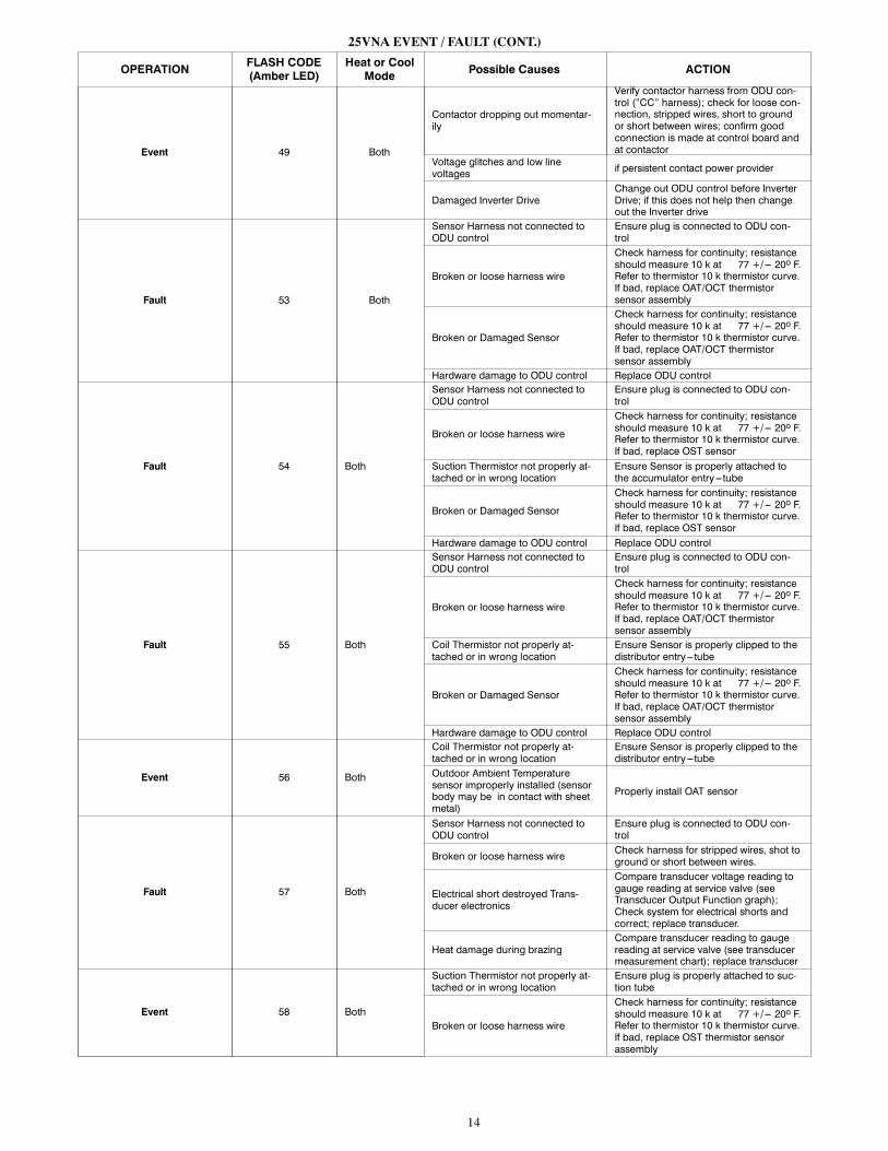
25VNA EVENT / FAULT (CONT.)
OPERATIONFLASH CODE(Amber LED)
Heat or CoolMode Possible Causes ACTION
Event 49 Both
Contactor dropping out momentar-ily
Verify contactor harness from ODU con-trol (”CC” harness); check for loose con-nection, stripped wires, short to groundor short between wires; confirm goodconnection is made at control board andat contactor
Voltage glitches and low linevoltages if persistent contact power provider
Damaged Inverter DriveChange out ODU control before InverterDrive; if this does not help then changeout the Inverter drive
Fault 53 Both
Sensor Harness not connected toODU control
Ensure plug is connected to ODU con-trol
Broken or loose harness wire
Check harness for continuity; resistanceshould measure 10 k at 77 +/--- 20o F.Refer to thermistor 10 k thermistor curve.If bad, replace OAT/OCT thermistorsensor assembly
Broken or Damaged Sensor
Check harness for continuity; resistanceshould measure 10 k at 77 +/--- 20o F.Refer to thermistor 10 k thermistor curve.If bad, replace OAT/OCT thermistorsensor assembly
Hardware damage to ODU control Replace ODU control
Fault 54 Both
Sensor Harness not connected toODU control
Ensure plug is connected to ODU con-trol
Broken or loose harness wire
Check harness for continuity; resistanceshould measure 10 k at 77 +/--- 20o F.Refer to thermistor 10 k thermistor curve.If bad, replace OST sensor
Suction Thermistor not properly at-tached or in wrong location
Ensure Sensor is properly attached tothe accumulator entry ---tube
Broken or Damaged Sensor
Check harness for continuity; resistanceshould measure 10 k at 77 +/--- 20o F.Refer to thermistor 10 k thermistor curve.If bad, replace OST sensor
Hardware damage to ODU control Replace ODU control
Fault 55 Both
Sensor Harness not connected toODU control
Ensure plug is connected to ODU con-trol
Broken or loose harness wire
Check harness for continuity; resistanceshould measure 10 k at 77 +/--- 20o F.Refer to thermistor 10 k thermistor curve.If bad, replace OAT/OCT thermistorsensor assembly
Coil Thermistor not properly at-tached or in wrong location
Ensure Sensor is properly clipped to thedistributor entry ---tube
Broken or Damaged Sensor
Check harness for continuity; resistanceshould measure 10 k at 77 +/--- 20o F.Refer to thermistor 10 k thermistor curve.If bad, replace OAT/OCT thermistorsensor assembly
Hardware damage to ODU control Replace ODU control
Event 56 Both
Coil Thermistor not properly at-tached or in wrong location
Ensure Sensor is properly clipped to thedistributor entry ---tube
Outdoor Ambient Temperaturesensor improperly installed (sensorbody may be in contact with sheetmetal)
Properly install OAT sensor
Fault 57 Both
Sensor Harness not connected toODU control
Ensure plug is connected to ODU con-trol
Broken or loose harness wireCheck harness for stripped wires, shot toground or short between wires.
Electrical short destroyed Trans-ducer electronics
Compare transducer voltage reading togauge reading at service valve (seeTransducer Output Function graph);Check system for electrical shorts andcorrect; replace transducer.
Heat damage during brazingCompare transducer reading to gaugereading at service valve (see transducermeasurement chart); replace transducer
Event 58 Both
Suction Thermistor not properly at-tached or in wrong location
Ensure plug is properly attached to suc-tion tube
Broken or loose harness wire
Check harness for continuity; resistanceshould measure 10 k at 77 +/--- 20o F.Refer to thermistor 10 k thermistor curve.If bad, replace OST thermistor sensorassembly
15
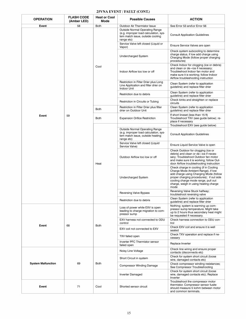
25VNA EVENT / FAULT (CONT.)
OPERATIONFLASH CODE(Amber LED)
Heat or CoolMode Possible Causes ACTION
Event 58 Both Outdoor Air Thermistor Issue See Error 53 and\or Error 56
Event 59
Cool
Outside Normal Operating Range(e.g. improper load calculation, sys-tem match issue, outside coolingrange etc)
Consult Application Guidelines
Service Valve left closed (Liquid orVapor) Ensure Service Valves are open
Undercharged System
Check system subcooling to determinecharge status, if low add charge usingCharging Mode (follow proper chargingprocedures)
Indoor Airflow too low or off
Check Indoor for clogging (ice or debris)and clean or de---ice if necessary;Troubleshoot Indoor fan motor andmake sure it is working; follow IndoorAirflow troubleshooting instruction
Restriction in Filter Drier plus LongLine Application and filter drier onIndoor Unit
Clean System (refer to applicationguideline) and replace filter drier
Restriction due to debrisClean System (refer to applicationguideline) and replace filter drier
Restriction in Circuits or TubingCheck kinks and straighten or replacecircuits
BothRestriction in Filter Drier plus filterdrier on Outdoor Unit
Clean System (refer to applicationguideline) and replace filter drier
Both Expansion Orifice RestrictionIf short lineset (less than 15 ft)Troubleshoot TXV (see guide below); re-place if necessary
Heat
Troubleshoot EXV (see guide below)Outside Normal Operating Range(e.g. improper load calculation, sys-tem match issue, outside heatingrange etc)
Consult Application Guidelines
Service Valve left closed (LiquidService Valve) Ensure Liquid Service Valve is open
Outdoor Airflow too low or off
Check Outdoor for clogging (ice ordebris) and clean or de---ice if neces-sary; Troubleshoot Outdoor fan motorand make sure it is working; follow Out-door Airflow troubleshooting instruction
Undercharged System
Check charge in cooling (if in CoolingCharge Mode Ambient Range), if lowadd charge using Charging Mode (followproper charging procedures); if out sidecooling charge mode range, pull outcharge, weigh in using heating chargemode
Reversing Valve BypassReversing Valve Stuck halfway;troubleshoot reversing valve
Restriction due to debrisClean System (refer to applicationguideline) and replace filter drier
Event 68 Both
Loss of power while EXV is openleading to charge migration to com-pressor sump
Nothing; system is warming up com-pressor sump temperature. Might takeup to 2 hours thus secondary heat mightbe requested if necessary.
EXV harness not connected to ODUcontrol
Check harness connection to ODU con-trol
EXV coil not connected to EXVCheck EXV coil and ensure it is wellseated
TXV failed openCheck TXV operation and replace if ne-cessary
Inverter PFC Thermistor sensorfailed open Replace Inverter
System Malfunction 69 Both
Noisy Line VoltageCheck line wiring and ensure propercontacts (disconnects etc)
Short Circuit in systemCheck for system short circuit (loosewire, damaged contacts etc)
Compressor Winding DamageCheck compressor winding resistances;See Compressor Troubleshooting
Inverter DamagedCheck for system short circuit (loosewire, damaged contacts etc); ReplaceInverter
Event 71 Cool Shorted sensor circuit
Troubleshoot the compressor motorthermistor. Compressor sensor fusiteshould measure 5 kohm between motorand common terminals.
16
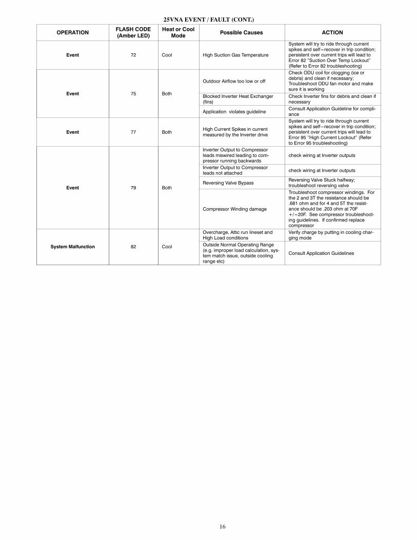
25VNA EVENT / FAULT (CONT.)
OPERATIONFLASH CODE(Amber LED)
Heat or CoolMode Possible Causes ACTION
Event 72 Cool High Suction Gas Temperature
System will try to ride through currentspikes and self ---recover in trip condition;persistent over current trips will lead toError 82 ”Suction Over Temp Lockout”(Refer to Error 82 troubleshooting)
Event 75 Both
Outdoor Airflow too low or off
Check ODU coil for clogging (ice ordebris) and clean if necessary;Troubleshoot ODU fan motor and makesure it is working
Blocked Inverter Heat Exchanger(fins)
Check Inverter fins for debris and clean ifnecessary
Application violates guidelineConsult Application Guideline for compli-ance
Event 77 BothHigh Current Spikes in currentmeasured by the Inverter drive
System will try to ride through currentspikes and self ---recover in trip condition;persistent over current trips will lead toError 95 ”High Current Lockout” (Referto Error 95 troubleshooting)
Event 79 Both
Inverter Output to Compressorleads miswired leading to com-pressor running backwards
check wiring at Inverter outputs
Inverter Output to Compressorleads not attached check wiring at Inverter outputs
Reversing Valve BypassReversing Valve Stuck halfway;troubleshoot reversing valve
Compressor Winding damage
Troubleshoot compressor windings. Forthe 2 and 3T the resistance should be.681 ohm and for 4 and 5T the resist-ance should be .203 ohm at 70F+/---20F. See compressor troubleshoot-ing guidelines. If confirmed replacecompressor
System Malfunction 82 Cool
Overcharge, Attic run lineset andHigh Load conditions
Verify charge by putting in cooling char-ging mode
Outside Normal Operating Range(e.g. improper load calculation, sys-tem match issue, outside coolingrange etc)
Consult Application Guidelines
17
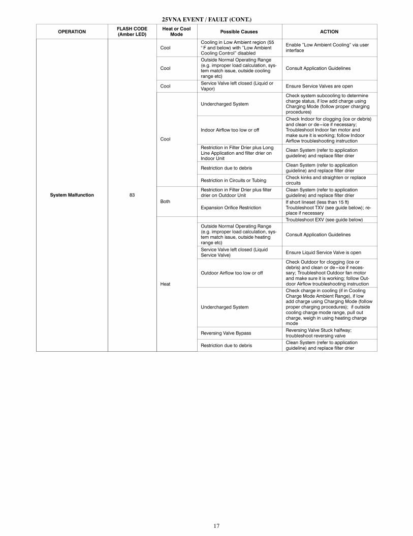
25VNA EVENT / FAULT (CONT.)
OPERATIONFLASH CODE(Amber LED)
Heat or CoolMode Possible Causes ACTION
System Malfunction 83
CoolCooling in Low Ambient region (55° F and below) with ”Low AmbientCooling Control” disabled
Enable ”Low Ambient Cooling” via userinterface
Cool
Outside Normal Operating Range(e.g. improper load calculation, sys-tem match issue, outside coolingrange etc)
Consult Application Guidelines
CoolService Valve left closed (Liquid orVapor) Ensure Service Valves are open
Cool
Undercharged System
Check system subcooling to determinecharge status, if low add charge usingCharging Mode (follow proper chargingprocedures)
Indoor Airflow too low or off
Check Indoor for clogging (ice or debris)and clean or de---ice if necessary;Troubleshoot Indoor fan motor andmake sure it is working; follow IndoorAirflow troubleshooting instruction
Restriction in Filter Drier plus LongLine Application and filter drier onIndoor Unit
Clean System (refer to applicationguideline) and replace filter drier
Restriction due to debrisClean System (refer to applicationguideline) and replace filter drier
Restriction in Circuits or TubingCheck kinks and straighten or replacecircuits
Both
Restriction in Filter Drier plus filterdrier on Outdoor Unit
Clean System (refer to applicationguideline) and replace filter drier
Expansion Orifice RestrictionIf short lineset (less than 15 ft)Troubleshoot TXV (see guide below); re-place if necessary
Heat
Troubleshoot EXV (see guide below)Outside Normal Operating Range(e.g. improper load calculation, sys-tem match issue, outside heatingrange etc)
Consult Application Guidelines
Service Valve left closed (LiquidService Valve) Ensure Liquid Service Valve is open
Outdoor Airflow too low or off
Check Outdoor for clogging (ice ordebris) and clean or de---ice if neces-sary; Troubleshoot Outdoor fan motorand make sure it is working; follow Out-door Airflow troubleshooting instruction
Undercharged System
Check charge in cooling (if in CoolingCharge Mode Ambient Range), if lowadd charge using Charging Mode (followproper charging procedures); if outsidecooling charge mode range, pull outcharge, weigh in using heating chargemode
Reversing Valve BypassReversing Valve Stuck halfway;troubleshoot reversing valve
Restriction due to debrisClean System (refer to applicationguideline) and replace filter drier
18
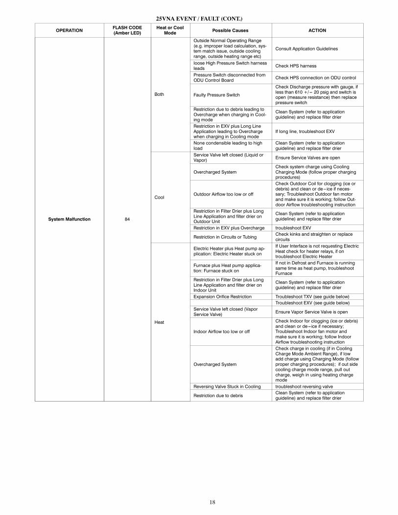
25VNA EVENT / FAULT (CONT.)
OPERATIONFLASH CODE(Amber LED)
Heat or CoolMode Possible Causes ACTION
System Malfunction 84
Both
Outside Normal Operating Range(e.g. improper load calculation, sys-tem match issue, outside coolingrange, outside heating range etc)
Consult Application Guidelines
loose High Pressure Switch harnessleads Check HPS harness
Pressure Switch disconnected fromODU Control Board Check HPS connection on ODU control
Faulty Pressure Switch
Check Discharge pressure with gauge, ifless than 610 +/--- 20 psig and switch isopen (measure resistance) then replacepressure switch
Restriction due to debris leading toOvercharge when charging in Cool-ing mode
Clean System (refer to applicationguideline) and replace filter drier
Restriction in EXV plus Long LineApplication leading to Overchargewhen charging in Cooling mode
If long line, troubleshoot EXV
None condensible leading to highload
Clean System (refer to applicationguideline) and replace filter drier
Cool
Service Valve left closed (Liquid orVapor) Ensure Service Valves are open
Overcharged SystemCheck system charge using CoolingCharging Mode (follow proper chargingprocedures)
Outdoor Airflow too low or off
Check Outdoor Coil for clogging (ice ordebris) and clean or de---ice if neces-sary; Troubleshoot Outdoor fan motorand make sure it is working; follow Out-door Airflow troubleshooting instruction
Restriction in Filter Drier plus LongLine Application and filter drier onOutdoor Unit
Clean System (refer to applicationguideline) and replace filter drier
Restriction in EXV plus Overcharge troubleshoot EXV
Restriction in Circuits or TubingCheck kinks and straighten or replacecircuits
Heat
Electric Heater plus Heat pump ap-plication: Electric Heater stuck on
If User Interface is not requesting ElectricHeat check for heater relays, if ontroubleshoot Electric Heater
Furnace plus Heat pump applica-tion: Furnace stuck on
If not in Defrost and Furnace is runningsame time as heat pump, troubleshootFurnace
Restriction in Filter Drier plus LongLine Application and filter drier onIndoor Unit
Clean System (refer to applicationguideline) and replace filter drier
Expansion Orifice Restriction Troubleshoot TXV (see guide below)Troubleshoot EXV (see guide below)
Service Valve left closed (VaporService Valve) Ensure Vapor Service Valve is open
Indoor Airflow too low or off
Check Indoor for clogging (ice or debris)and clean or de---ice if necessary;Troubleshoot Indoor fan motor andmake sure it is working; follow IndoorAirflow troubleshooting instruction
Overcharged System
Check charge in cooling (if in CoolingCharge Mode Ambient Range), if lowadd charge using Charging Mode (followproper charging procedures); if out sidecooling charge mode range, pull outcharge, weigh in using heating chargemode
Reversing Valve Stuck in Cooling troubleshoot reversing valve
Restriction due to debrisClean System (refer to applicationguideline) and replace filter drier
19
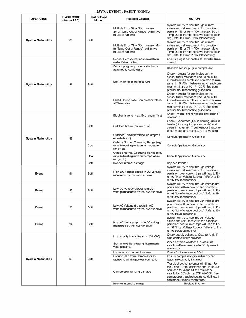
25VNA EVENT / FAULT (CONT.)
OPERATIONFLASH CODE(Amber LED)
Heat or CoolMode Possible Causes ACTION
System Malfunction 85 Both
Multiple Error 59 --- ”CompressorScroll Temp Out of Range” within twohours of run time
System will try to ride through currentspikes and self ---recover in trip condition;persistent Error 59 --- ”Compressor ScrollTemp Out of Range” trips will lead to Error88; (Refer to Error 59 troubleshooting)
Multiple Error 71 --- ”Compressor Mo-tor Temp Out of Range” within twohours of run time
System will try to ride through currentspikes and self ---recover in trip condition;persistent Error 71 --- ”Compressor MotorTemp Out of Range” trips will lead to Error88; (Refer to Error 71 troubleshooting)
System Malfunction 86 Both
Sensor Harness not connected to In-verter Drive control
Ensure plug is connected to Inverter Drivecontrol
Sensor plug not properly sited or notattached to compressor Reattach sensor plug to compressor
Broken or loose harness wire
Check harness for continuity; on thesensor fusite resistance should be in 10kOhm between scroll and common termin-als and 5 kOhm between motor and com-mon terminals at 70 +/--- 20 F. See com-pressor troubleshooting guidelines
Failed Open/Close Compressor Intern-al Thermistor
Check harness for continuity; on thesensor fusite resistance should be in 10kOhm between scroll and common termin-als and 5 kOhm between motor and com-mon terminals at 70 +/--- 20 F. See com-pressor troubleshooting guidelines
System Malfunction 88
Both
Blocked Inverter Heat Exchanger (fins)Check Inverter fins for debris and clean ifnecessary
Outdoor Airflow too low or off
Check Evaporator (IDU in cooling, ODU inheating) for clogging (ice or debris) andclean if necessary; Troubleshoot Evaporat-or fan motor and make sure it is working
Outdoor Unit airflow blocked (improp-er installation) Consult Application Guidelines
CoolOutside Normal Operating Range (e.g.outside cooling ambient temperaturerange etc)
Consult Application Guidelines
HeatOutside Normal Operating Range (e.g.outside heating ambient temperaturerange etc)
Consult Application Guidelines
Both Inverter internal damage Replace Inverter
Event 91 BothHigh DC Voltage spikes in DC voltagemeasured by the Inverter drive
System will try to ride through voltagespikes and self ---recover in trip condition;persistent over current trips will lead to Er-ror 97 ”High Voltage Lockout” (Refer to Er-ror 97 troubleshooting)
Event 92 BothLow DC Voltage dropouts in DCvoltage measured by the Inverter drive
System will try to ride through voltage dro-pouts and self ---recover in trip condition;persistent over current trips will lead to Er-ror 96 ”Low Voltage Lockout” (Refer to Er-ror 96 troubleshooting)
Event 93 BothLow AC Voltage dropouts in ACvoltage measured by the Inverter drive
System will try to ride through voltage dro-pouts and self ---recover in trip condition;persistent over current trips will lead to Er-ror 96 ”Low Voltage Lockout” (Refer to Er-ror 96 troubleshooting)
Event 94 BothHigh AC Voltage spikes in AC voltagemeasured by the Inverter drive
System will try to ride through voltagespikes and self ---recover in trip condition;persistent over current trips will lead to Er-ror 97 ”High Voltage Lockout” (Refer to Er-ror 97 troubleshooting)
System Malfunction 95 Both
High supply line voltage (> 257 VAC)Check supply voltage to Outdoor Unit; ifhigh contact utility provider
Stormy weather causing intermittentvoltage spikes
When adverse weather subsides unitshould self ---recover; cycle ODU power ifnecessary
Loose wire in control box area Check for loose wire in ODUGround lead from Compressor at-tached to winding power connection
Ensure compressor ground and otherleads are correctly installed
Compressor Winding damage
Troubleshoot compressor windings. Forthe 2 and 3T the resistance should be .681ohm and for 4 and 5T the resistanceshould be .203 ohm at 70F +/---20F. Seecompressor troubleshooting guidelines. Ifconfirmed replace compressor
Inverter internal damage Replace Inverter
20
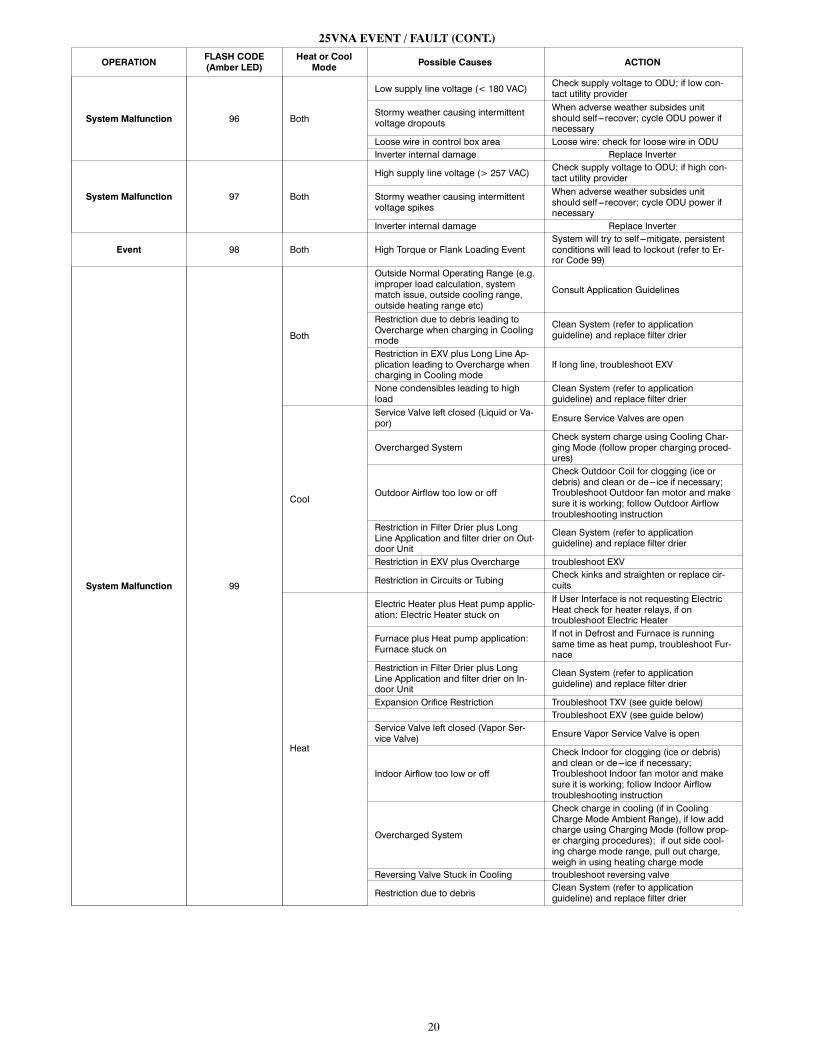
25VNA EVENT / FAULT (CONT.)
OPERATIONFLASH CODE(Amber LED)
Heat or CoolMode Possible Causes ACTION
System Malfunction 96 Both
Low supply line voltage (< 180 VAC)Check supply voltage to ODU; if low con-tact utility provider
Stormy weather causing intermittentvoltage dropouts
When adverse weather subsides unitshould self ---recover; cycle ODU power ifnecessary
Loose wire in control box area Loose wire: check for loose wire in ODUInverter internal damage Replace Inverter
System Malfunction 97 Both
High supply line voltage (> 257 VAC)Check supply voltage to ODU; if high con-tact utility provider
Stormy weather causing intermittentvoltage spikes
When adverse weather subsides unitshould self ---recover; cycle ODU power ifnecessary
Inverter internal damage Replace Inverter
Event 98 Both High Torque or Flank Loading EventSystem will try to self ---mitigate, persistentconditions will lead to lockout (refer to Er-ror Code 99)
System Malfunction 99
Both
Outside Normal Operating Range (e.g.improper load calculation, systemmatch issue, outside cooling range,outside heating range etc)
Consult Application Guidelines
Restriction due to debris leading toOvercharge when charging in Coolingmode
Clean System (refer to applicationguideline) and replace filter drier
Restriction in EXV plus Long Line Ap-plication leading to Overcharge whencharging in Cooling mode
If long line, troubleshoot EXV
None condensibles leading to highload
Clean System (refer to applicationguideline) and replace filter drier
Cool
Service Valve left closed (Liquid or Va-por) Ensure Service Valves are open
Overcharged SystemCheck system charge using Cooling Char-ging Mode (follow proper charging proced-ures)
Outdoor Airflow too low or off
Check Outdoor Coil for clogging (ice ordebris) and clean or de---ice if necessary;Troubleshoot Outdoor fan motor and makesure it is working; follow Outdoor Airflowtroubleshooting instruction
Restriction in Filter Drier plus LongLine Application and filter drier on Out-door Unit
Clean System (refer to applicationguideline) and replace filter drier
Restriction in EXV plus Overcharge troubleshoot EXV
Restriction in Circuits or TubingCheck kinks and straighten or replace cir-cuits
Heat
Electric Heater plus Heat pump applic-ation: Electric Heater stuck on
If User Interface is not requesting ElectricHeat check for heater relays, if ontroubleshoot Electric Heater
Furnace plus Heat pump application:Furnace stuck on
If not in Defrost and Furnace is runningsame time as heat pump, troubleshoot Fur-nace
Restriction in Filter Drier plus LongLine Application and filter drier on In-door Unit
Clean System (refer to applicationguideline) and replace filter drier
Expansion Orifice Restriction Troubleshoot TXV (see guide below)Troubleshoot EXV (see guide below)
Service Valve left closed (Vapor Ser-vice Valve) Ensure Vapor Service Valve is open
Indoor Airflow too low or off
Check Indoor for clogging (ice or debris)and clean or de---ice if necessary;Troubleshoot Indoor fan motor and makesure it is working; follow Indoor Airflowtroubleshooting instruction
Overcharged System
Check charge in cooling (if in CoolingCharge Mode Ambient Range), if low addcharge using Charging Mode (follow prop-er charging procedures); if out side cool-ing charge mode range, pull out charge,weigh in using heating charge mode
Reversing Valve Stuck in Cooling troubleshoot reversing valve
Restriction due to debrisClean System (refer to applicationguideline) and replace filter drier
21
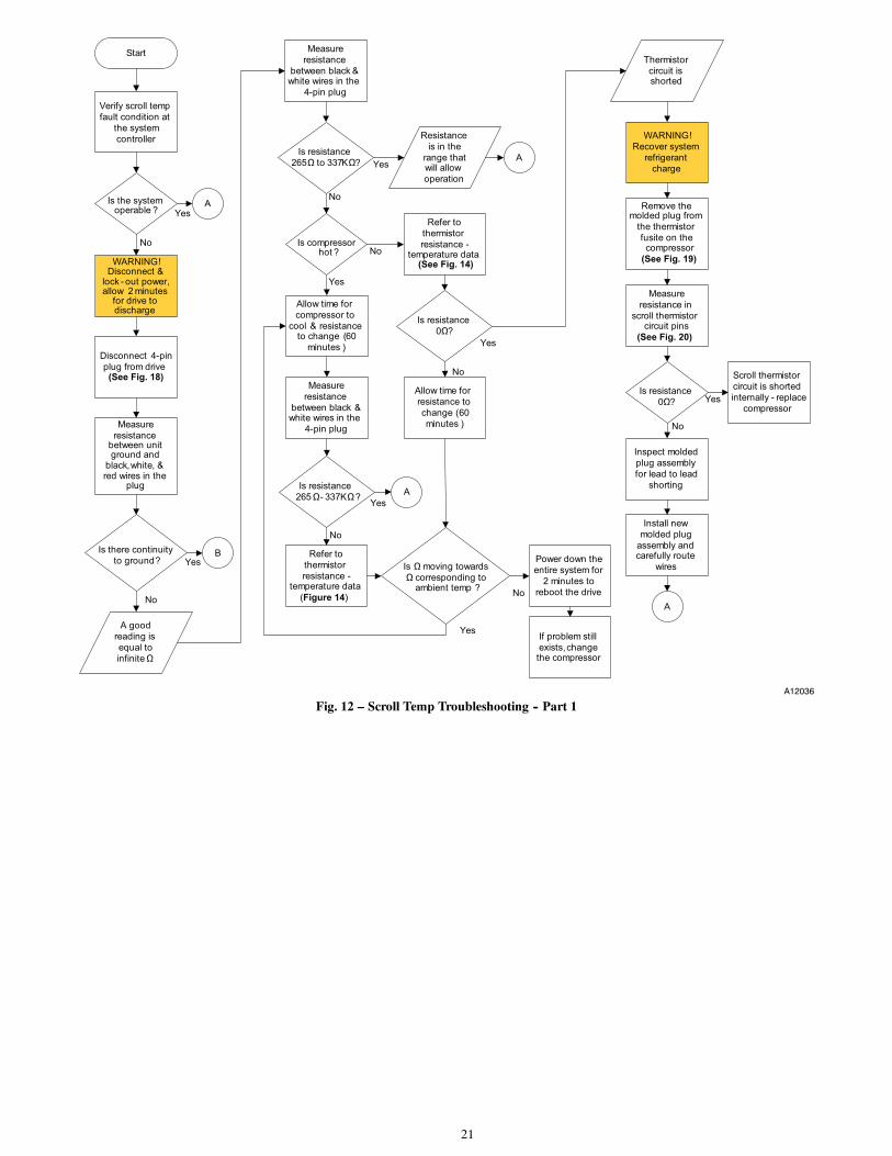
Start
Verify scroll temp
fault condition at
the system
controller
Disconnect 4-pin
plug from drive (See Fig. 18)
Measure
resistance
between black & white wires in the
4-pin plug
Is resistance
265Ω to 337KΩ?
Yes
No
Is resistance
265 Ω- 337KΩ?
Allow time for
compressor to
cool & resistance to change (60
minutes )
Is Ω moving towards
Ω corresponding to ambient temp ?
Resistance
is in the
range that will allow
operation
Yes
No
Measure
resistance between unit ground and
black, white, & red wires in the
plug
Is there continuity
to ground?
Yes
No
Is the system operable ?
A Yes
No
B
Is compressor hot ?
AYes
No
Measure
resistance
between black & white wires in the
4-pin plug
Is resistance
0Ω?
A good
reading is
equal to
infinite Ω
Refer to
thermistor
resistance -
Figure
temperature data(See Fig. 14)WARNING!
Disconnect & lock - out power, allow 2 minutes
for drive to discharge
A
No
Yes
No
If problem still
exists, change the compressor
Refer to
thermistor
resistance -temperature data
(Figure 14)
Yes
Power down the
entire system for
2 minutes to
reboot the drive
Allow time for
resistance to
change (60
minutes )
WARNING!
Recover system
refrigerant
charge
Thermistor
circuit is shorted
Remove the molded plug from
the thermistor
fusite on the compressor
(See Fig. 19)
Measure
resistance in
scroll thermistor circuit pins
Is resistance
0Ω? Yes
No
Scroll thermistor
circuit is shorted
internally - replace
compressor
Inspect molded
plug assembly
for lead to lead
shorting
Install new
molded plug
assembly and carefully route
wires
A
(See Fig. 20)
A12036
Fig. 12 – Scroll Temp Troubleshooting -- Part 1
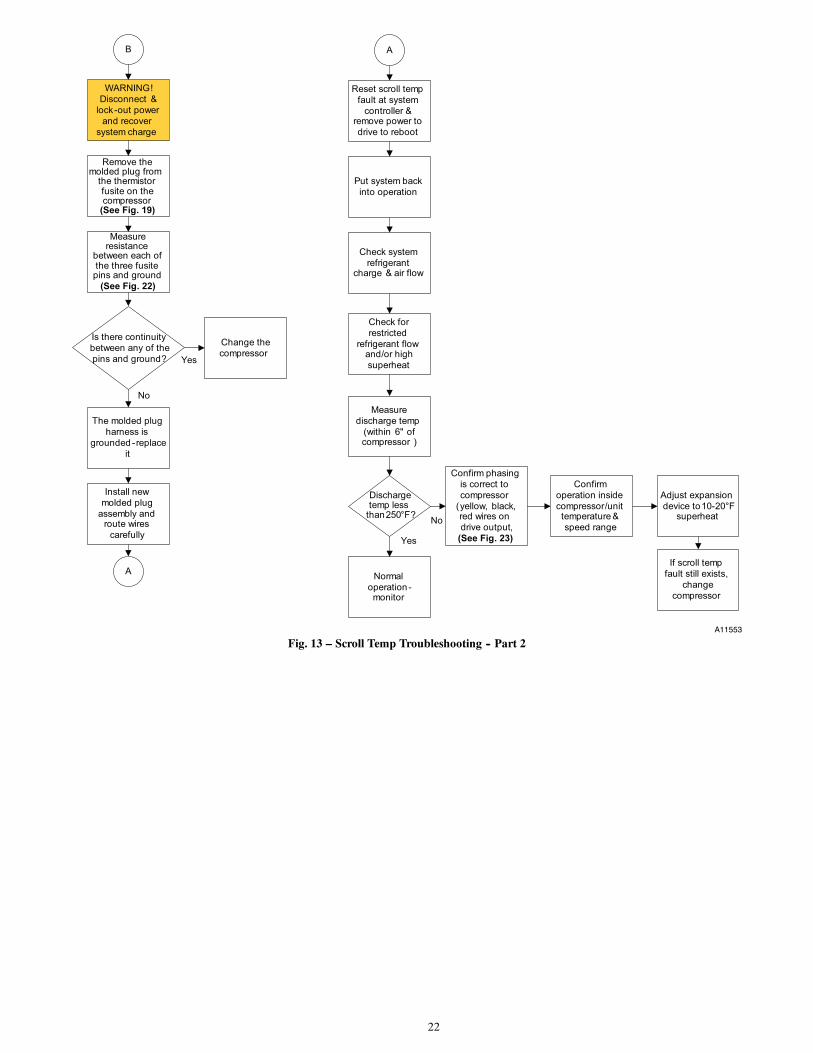
22
Check system
refrigerant charge & air flow
Measure
discharge temp
(within 6" of compressor )
WARNING!
Disconnect &
lock-out power
and recover
system charge
Measure resistance
between each of the three fusite pins and ground
(See Fig. 22)
Discharge temp less
than 250 °F?
Normal
operation -monitor
Check for
restricted
refrigerant flow and/or high
superheat
Remove the molded plug from
the thermistor fusite on the compressor
(See Fig. 19)
The molded plug
harness is
grounded -replace
it
Put system back
into operation
Yes
Install new
molded plug
assembly and route wires
carefully
Is there continuity
between any of the
pins and ground?
If scroll temp
fault still exists,
change
compressor
AB
Reset scroll temp
fault at system
controller & remove power to
drive to reboot
A
No
Change the
compressor
No
Yes
Confirm phasing
is correct to
compressor
(yellow, black, red wires on
drive output,
(See Fig. 23)
Confirm
operation inside
compressor/unit temperature &
speed range
Adjust expansion
device to 10-20°F superheat
A11553
Fig. 13 – Scroll Temp Troubleshooting -- Part 2
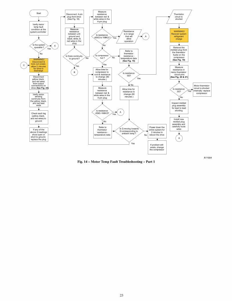
23
Start
Verify motor
temp fault
condition at the
system controller
Disconnect 4-pin
plug from drive (See Fig. 18)
Measure
resistance
between red & white wires in the
4-pin plug
Is resistance
459Ω to 168KΩ ?
Yes
No
Is resistance
459Ω -168KΩ?
Allow time for
compressor to
cool & resistance to change (60
minutes )
Is Ω moving towards
Ω corresponding to ambient temp ?
Resistance
is in range
that will allow
operation
Yes
No
Measure resistance
between unit
ground and black, white, & red wires in the
plug
Is there continuity
to ground?
Yes
No
Is the system
operable ?A
Yes
No
B
Is compressor
hot ?
AYes
No
Measure
resistance
between red & white wires in the
4-pin plug
Is resistance
0Ω?
Refer to
thermistor
resistance -temperature data
(See Fig. 15)WARNING!Disconnect &
lock-out power,
allow 2 minutes for drive to discharge
A
No
Yes
No
If problem still
exists, change the compressor
Refer to
thermistor
resistance -
temperature data
Yes
Power down the
entire system for
2 minutes to
reboot the drive
Allow time for
resistance to
change (60
minutes )
WARNING!
Recover system
refrigerant
charge
Thermistor
circuit is shorted
Remove the molded plug from
the thermistor
fusite on the
compressor
(See Fig. 19)
Measure
resistance in
motor thermistor circuit pins
(See Fig. 20 & 21)
Is resistance
0Ω? Yes
No
Motor thermistor
circuit is shorted
internally - replace
compressor
Inspect molded
plug assembly
for lead to lead
shorting
Install new
molded plug
assembly and carefully route
wires
A
C
Disconnect yellow, black, and red wires from output
connections on drive (See Fig. 23)
Verify motor winding
continuity from the yellow, black,
and red lead ends
Check each leg
(yellow, black,
and red wires) to
ground
If any of the
above Ω readings
show open or short to ground,
replace the plug
A11554
Fig. 14 – Motor Temp Fault Troubleshooting -- Part 1
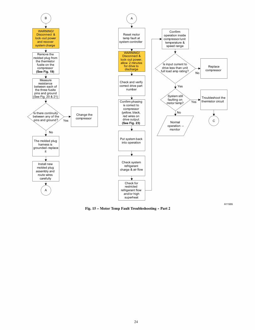
24
Check system
refrigerant
charge & air flow
WARNING! Disconnect &
lock-out power
and recover
system charge
Measure resistance
between each of the three fusite pins and ground
(See Fig. 20 & 21)
Check for restricted
refrigerant flow
and/or high
superheat
Remove the
molded plug from the thermistor fusite on the compressor
(See Fig. 19)
The molded plug
harness is grounded -replace
it
Put system back
into operation
Yes
Install new
molded plug
assembly and
route wires
carefully
Is there continuity between any of the
pins and ground?
AB
Reset motor
temp fault at
system controller
A
No
Change the
compressor
No
Yes
Confirm phasing
is correct to
compressor
(yellow, black,
red wires on drive output.
(See Fig. 23)
Confirm
operation inside
compressor/unit
temperature & speed range
Check and verify
correct drive part
number
System still
faulting on motor temp?
Normal
operation --
monitor
Troubleshoot the
thermistor circuit
C
Is input current to
drive less than unit full load amp rating?
Replace
compressor
Yes
No
WARNING!Disconnect &
lock-out power, allow 2 minutes
for drive to discharge
A11555
Fig. 15 – Motor Temp Fault Troubleshooting -- Part 2
25
Low Temp Trip
High Temp Trip150
300
600
1200
2400
4800
9600
19200
38400
76800
153600
307200
-45 -25 -5 15 35 55 75 95 115 135 155 175 195 215 235 255 275 295
Ther
mist
or R
esist
ance
(Ohm
s)
Temperature (°F)
Scroll Thermistor Resistance
A12038
Fig. 16 – Scroll Thermistor Resistance
Low Temp Trip
High Temp Trip400
800
1600
3200
6400
12800
25600
51200
102400
204800
-45 -25 -5 15 35 55 75 95 115 135 155 175 195
Para
lled
Ther
mis
tor
Resi
stan
ce (O
hms)
Temperature (°F)
Motor Thermistor Resistance
A12039
Fig. 17 – Motor Thermistor Resistance
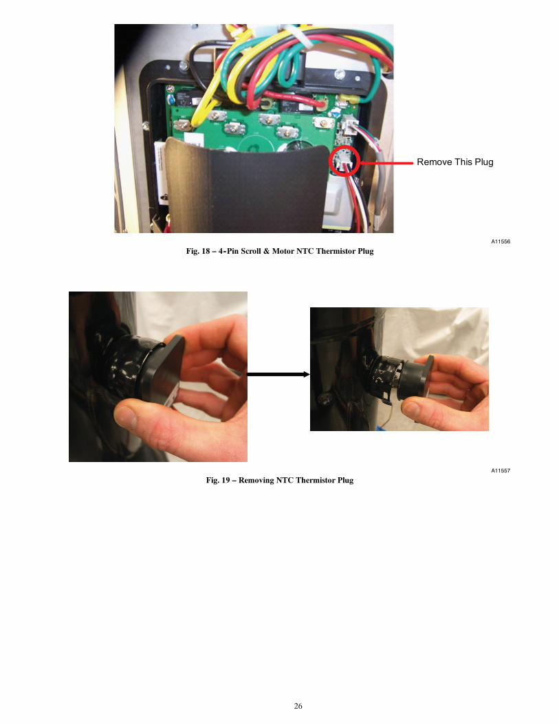
26
Remove This Plug
A11556
Fig. 18 – 4--Pin Scroll & Motor NTC Thermistor Plug
A11557
Fig. 19 – Removing NTC Thermistor Plug
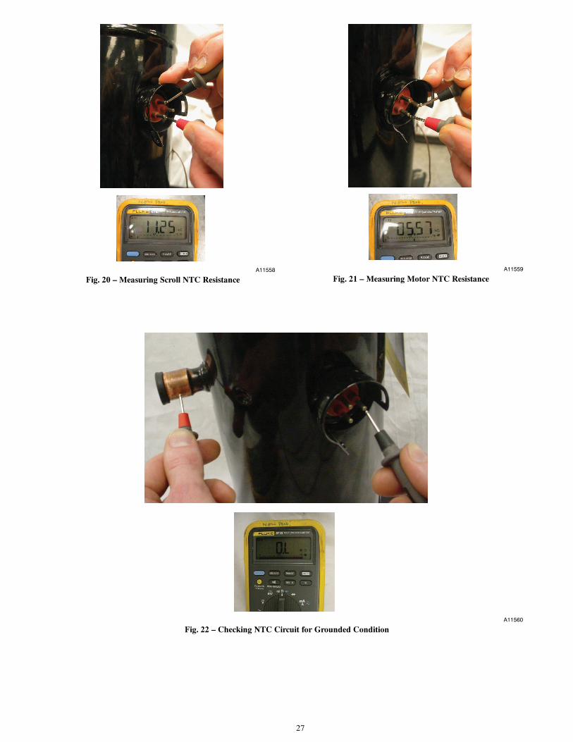
27
A11558
Fig. 20 – Measuring Scroll NTC ResistanceA11559
Fig. 21 – Measuring Motor NTC Resistance
A11560
Fig. 22 – Checking NTC Circuit for Grounded Condition
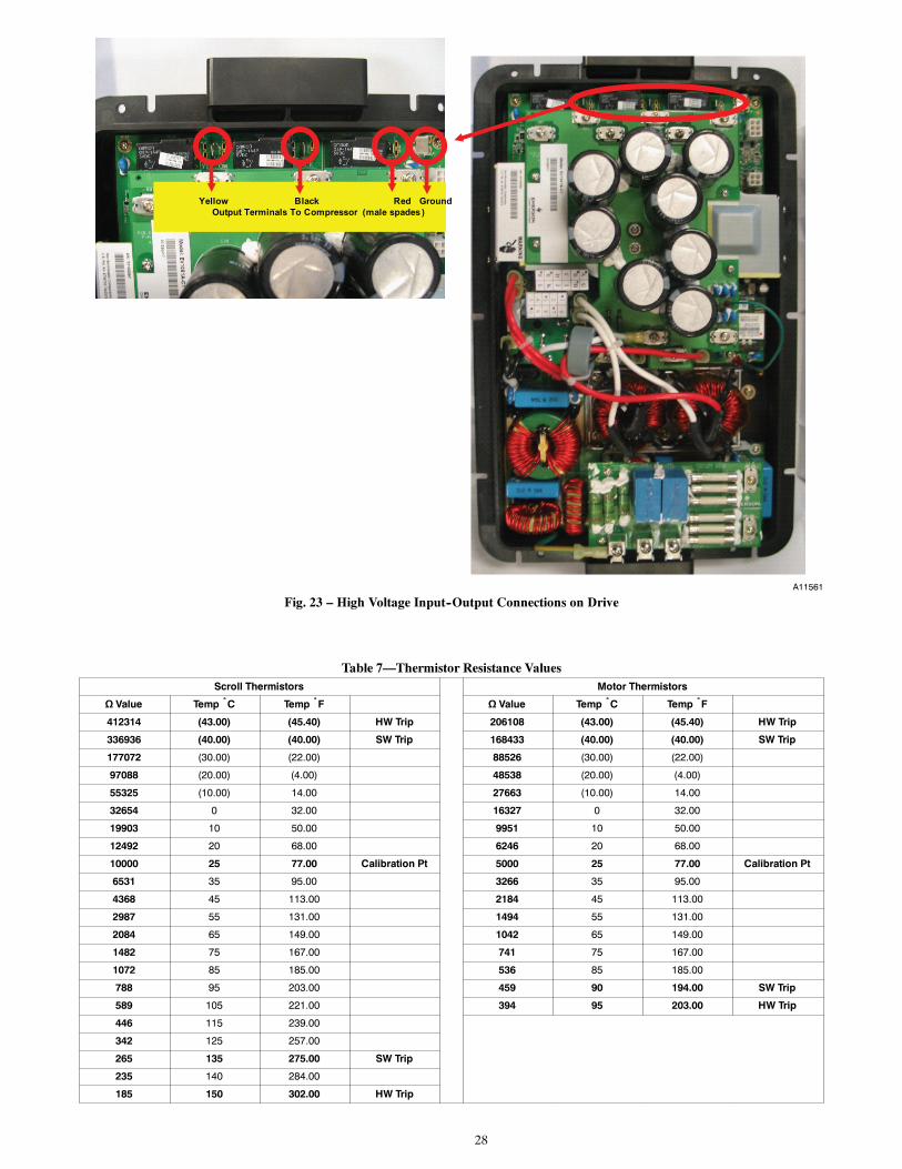
28
Yellow Black Red GroundOutput Terminals To Compressor (male spades )
A11561
Fig. 23 – High Voltage Input--Output Connections on Drive
Table 7—Thermistor Resistance ValuesScroll Thermistors Motor Thermistors
Ω Value Temp ˚C Temp ˚F Ω Value Temp ˚C Temp ˚F
412314 (43.00) (45.40) HW Trip 206108 (43.00) (45.40) HW Trip
336936 (40.00) (40.00) SW Trip 168433 (40.00) (40.00) SW Trip
177072 (30.00) (22.00) 88526 (30.00) (22.00)
97088 (20.00) (4.00) 48538 (20.00) (4.00)
55325 (10.00) 14.00 27663 (10.00) 14.00
32654 0 32.00 16327 0 32.00
19903 10 50.00 9951 10 50.00
12492 20 68.00 6246 20 68.00
10000 25 77.00 Calibration Pt 5000 25 77.00 Calibration Pt
6531 35 95.00 3266 35 95.00
4368 45 113.00 2184 45 113.00
2987 55 131.00 1494 55 131.00
2084 65 149.00 1042 65 149.00
1482 75 167.00 741 75 167.00
1072 85 185.00 536 85 185.00
788 95 203.00 459 90 194.00 SW Trip
589 105 221.00 394 95 203.00 HW Trip
446 115 239.00
342 125 257.00
265 135 275.00 SW Trip
235 140 284.00
185 150 302.00 HW Trip
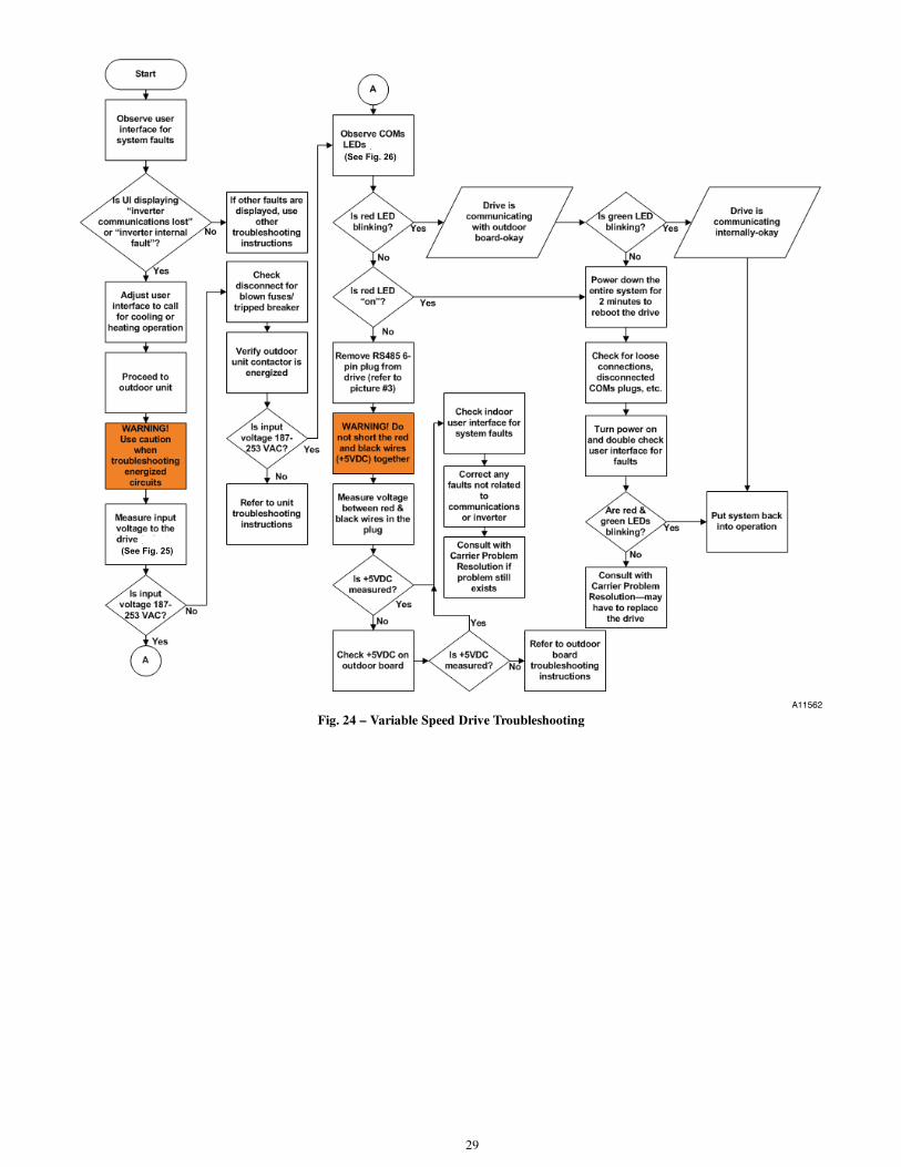
29
(See Fig. 26)
(See Fig. 25)
A11562
Fig. 24 – Variable Speed Drive Troubleshooting
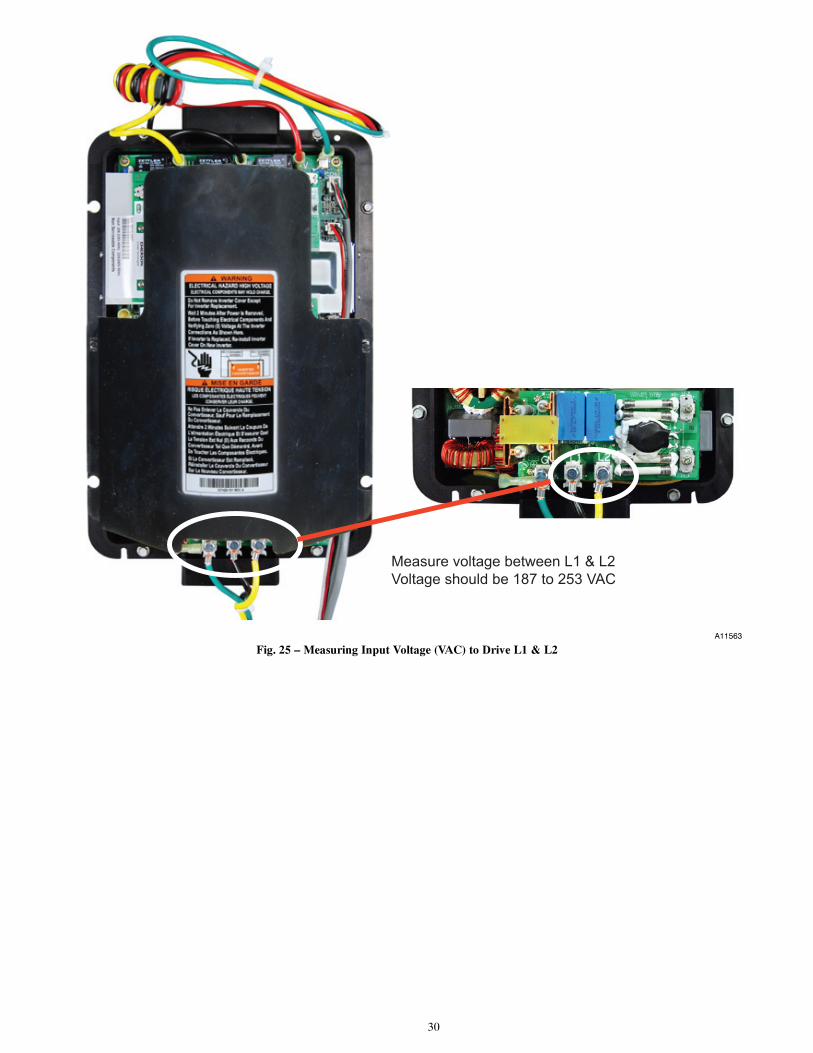
30
Measure voltage between L1 & L2
Voltage should be 187 to 253 VAC
A11563
Fig. 25 – Measuring Input Voltage (VAC) to Drive L1 & L2
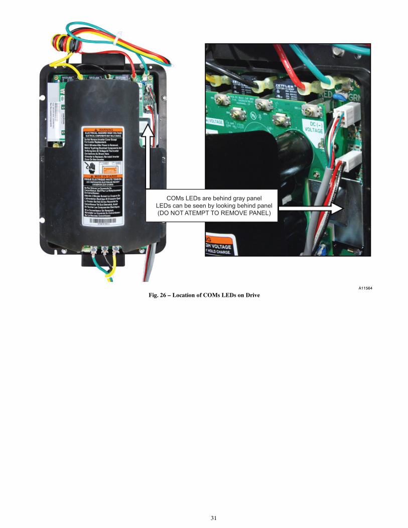
31
COMs LEDs are behind gray panel
LEDs can be seen by looking behind panel
(DO NOT ATEMPT TO REMOVE PANEL)
A11564
Fig. 26 – Location of COMs LEDs on Drive
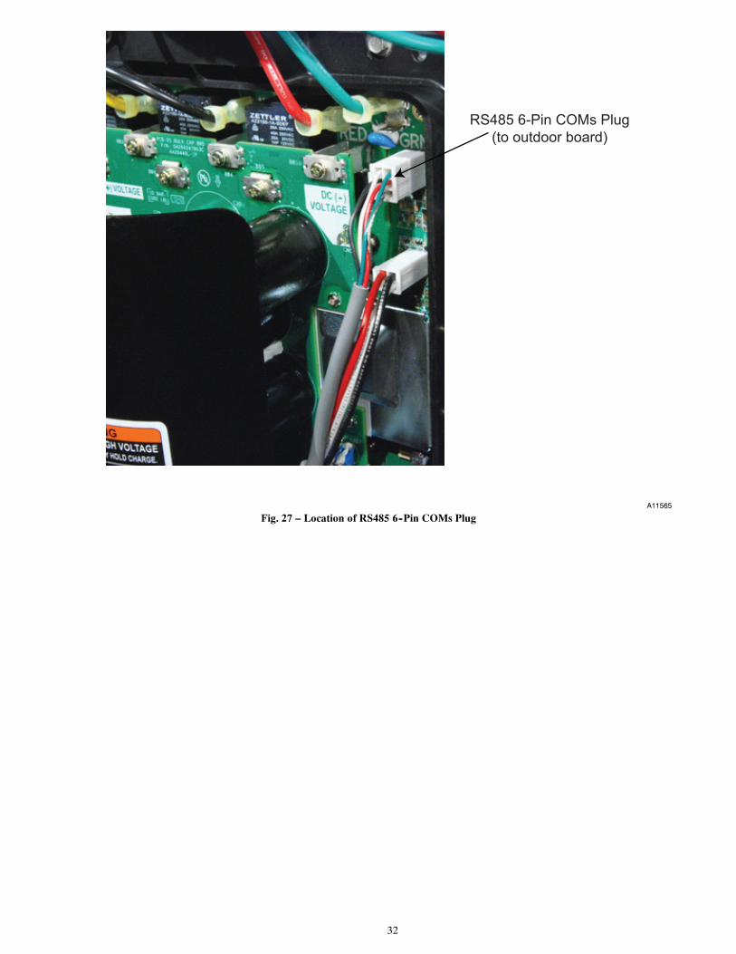
32
RS485 6-Pin COMs Plug
(to outdoor board)
A11565
Fig. 27 – Location of RS485 6--Pin COMs Plug
33
REFRIGERATION SYSTEMRefrigerant
UNIT OPERATION AND SAFETY HAZARD
Failure to follow this warning could result in personal injuryor equipment damage.
Puronr refrigerant which has higher pressures than R--22 andother refrigerants. No other refrigerant may be used in thissystem. Gauge set, hoses, and recovery system must bedesigned to handle Puronr. If you are unsure consult theequipment manufacturer.
! WARNING
In an air conditioning and heat pump system, refrigerant transfersheat from one replace to another. The condenser is the outdoor coilin the cooling mode and the evaporator is the indoor coil.
In a heat pump, the condenser is the indoor coil in the heatingmode and the evaporator is the outdoor coil.
In the typical air conditioning mode, compressed hot gas leaves thecompressor and enters the condensing coil. As gas passes throughthe condenser coil, it rejects heat and condenses into liquid. Theliquid leaves condensing unit through liquid line and entersmetering device at evaporator coil. As it passes through meteringdevice, it becomes a gas--liquid mixture. As it passes throughindoor coil, it absorbs heat and the refrigerant moves to thecompressor and is again compressed to hot gas, and cycle repeats.
Compressor Oil
UNIT DAMAGE HAZARD
Failure to follow this caution may result in equipmentdamage or improper operation.
The compressor in a Puronr system uses a polyol ester(POE) oil. This oil is extremely hygroscopic, meaning itabsorbs water readily. POE oils can absorb 15 times as muchwater as other oils designed for HCFC and CFC refrigerants.Take all necessary precautions to avoid exposure of the oil tothe atmosphere.
CAUTION!
Servicing Systems on Roofs With SyntheticMaterialsPOE (polyol ester) compressor lubricants are known to cause longterm damage to some synthetic roofing materials. Exposure, even ifimmediately cleaned up, may cause embrittlement (leading tocracking) to occur in one year or more. When performing anyservice which may risk exposure of compressor oil to the roof, takeappropriate precautions to protect roofing. Procedures which riskoil leakage include but are not limited to compressor replacement,repairing refrigerants leaks, replacing refrigerant components suchas filter drier, pressure switch, metering device, coil, accumulator,or reversing valve.
Synthetic Roof Precautionary Procedure
1. Cover extended roof working area with an impermeablepolyethylene (plastic) drop cloth or tarp. Cover anapproximate 10 x 10 ft area.
2. Cover area in front of the unit service panel with a terrycloth shop towel to absorb lubricant spills and preventrun--offs, and protect drop cloth from tears caused by toolsor components.
3. Place terry cloth shop towel inside unit immediately undercomponent(s) to be serviced and prevent lubricant run--offsthrough the louvered openings in the base pan.
4. Perform required service.
5. Remove and dispose of any oil contaminated material perlocal codes.
BrazingThis section on brazing is not intended to teach a technician how tobraze. There are books and classes which teach and refine brazingtechniques. The basic points below are listed only as a reminder.
Definition: The joining and sealing of metals using a nonferrousmetal having a melting point over 800_F/426.6_C.
Flux: A cleaning solution applied to tubing or wire before it isbrazed. Flux improves the strength of the brazed connection.
When brazing is required in the refrigeration system, certain basicsshould be remembered. The following are a few of the basic rules.
1. Clean joints make the best joints. To clean:
⎯ Remove all oxidation from surfaces to a shinyfinish before brazing.
⎯ Remove all flux residue with brush and water whilematerial is still hot.
2. Silver brazing alloy is used on copper--to--brass,copper--to--steel, or copper--to--copper. Flux is requiredwhen using silver brazing alloy. Do not use low temperaturesolder.
3. Fluxes should be used carefully. Avoid excessiveapplication and do not allow fluxes to enter into the system.
4. Brazing temperature of copper is proper when it is heated toa minimum temperature of 800_F and it is a dull red colorin appearance.
34
Service Valves and Pumpdown
PERSONAL INJURY AND UNIT DAMAGE HAZARD
Failure to follow this warning could result in personal injuryor equipment damage.
Never attempt to make repairs to existing service valves. Unitoperates under high pressure. Damaged seats and o--ringsshould not be replaced. Replacement of entire service valve isrequired. Service valve must be replaced by properly trainedservice technician.
! WARNING
Service valves provide a means for holding original factory chargein outdoor unit prior to hookup to indoor coil. They also containgauge ports for measuring system pressures and provide shutoffconvenience for certain types of repairs. (See Fig. 28)
The service valve is a front--seating valve, which has a service portthat contains a Schrader fitting. The service port is alwayspressurized after the valve is moved off the front--seat position.
The service valves in the outdoor unit come from the factoryfront--seated. This means that the refrigerant charge is isolated fromthe line--set connection ports. The interconnecting tubing (line set)can be brazed to the service valves using industry acceptedmethods and materials. Consult local codes.
Before brazing the line set to the valve, the belled ends of the sweatconnections on the service valves must be cleaned so that no brassplating remains on either the inside or outside of the bell joint. Toprevent damage to the valve and/or cap “O” ring, use a wet clothor other acceptable heat--sinking material on the valve beforebrazing. To prevent damage to the unit, use a metal barrier betweenbrazing area and unit.
After the brazing operation and the refrigerant tubing andevaporator coil have been evacuated, the valve stem can be turnedcounterclockwise until back--seats, which releases refrigerant intotubing and evaporator coil. The system can now be operated.
The service valve--stem cap is tightened to 20 ± 2 ft/lb torque andthe service--port caps to 9 ± 2 ft/lb torque. The seating surface ofthe valve stem has a knife--set edge against which the caps aretightened to attain a metal--to--metal seal.
The service valve cannot be field repaired; therefore, only acomplete valve or valve stem and service--port caps are availablefor replacement.
If the service valve is to be replaced, a metal barrier must beinserted between the valve and the unit to prevent damaging theunit exterior from the heat of the brazing operations.
PERSONAL INJURY HAZARD
Failure to follow this caution may result in personal injury.
Wear safety glasses, protective clothing, and gloves whenhandling refrigerant.
CAUTION!
Pumpdown & Evacuation
If this system requires either a Pump Down or Evacuation for anyreason, the procedures below must be followed:
Pump Down
Because this system has an inverter controlled, compressor, suctionpressure transducer and EXV, conventional procedure cannot beused to “pump down” and isolate the refrigerant into the outdoorunit. The UI (User Interface) has provisions to assist in performingthis function.
1. Connect gages to 25VNA liquid and vapor or suction capil-lary service ports to monitor operating pressures during andat completion of the procedure.
2. In the advanced menu of the UI, go to Checkout > HeatPump> Pumpdown
3. Select mode to pump down in (COOL or HEAT), COOLmode allows refrigerant to be isolated in outdoor unit.HEAT mode allows the refrigerant to be isolated in indoorcoil and lineset. Set desired time period. Default time peri-od for the procedure is 120 minutes.
4. Select Start on UI to begin the pumpdown process. Unitwill begin running in selected mode after a brief delay.
5. Close the liquid service valve.
6. The unit will run in selected mode with the low pressureprotection set to indicate pumpdown is complete when thesuction pressure drops below 0 psig. Compressor protec-tions are still active to prevent damage to the compressor orinverter (high pressure, high current, high torque, scrolltemperature, etc.) .
7. Once system indicates pumpdown complete or failure tocomplete shutdown, close vapor service valve.
8. If pumpdown does not complete due to compressor safetyshutdown, a recovery system will be required to remove fi-nal quantity of refrigerant from indoor coil and line set.
9. Remove power from indoor and heat pump unit prior to ser-vicing unit.
NOTE: A small quantity of charge remains in the OD unit thatmust be manually recovered if isolating refrigerant to indoor coiland lineset via HEAT mode PUMP DOWN.Evacuation and Recovery of Refrigerant from within25VNA
ENVIRONMENTAL HAZARD
Failure to follow this caution may result in environmentaldamage.
Federal regulations require that you do not vent refrigerant tothe atmosphere. Recover during system repair or final unitdisposal.
CAUTION!
Because this system has an EXV for the heating expansion device,additional steps must be taken to open the EXV if the heat pumpunit must be evacuated for service reasons. If the EXV is not openwhen pulling a vacuum or recovering refrigerant from the heatpump unit, extended evacuation time may be required and/orinadequate vacuum obtained. The UI (User Interface) hasprovisions to open the EXV for refrigerant recovery and/orevacuation.
1. Connect gages to 25VNA liquid and vapor or suction capil-lary service ports to monitor operating pressures during andat completion of the procedure. Attach recovery system orvacuum pump to gage set as needed for the service proced-ure. The service valves must be open to evacuate the unitthrough the line set service ports. The suction capillary ser-vice port is a direct connection to the suction port of thecompressor.
2. In the advanced menu of the UI, go to Checkout > HeatPump> > Evacuation.
3. Set desired time period. Default time period for the proced-ure is 120 minutes.
4. Select START on UI to open the valve.
5. Begin evacuation or refrigerant recovery as required for theprocedure after UI indicates the EXV is open. Power maybe removed from heat pump after the UI indicates “READYTO EVACUATE.”
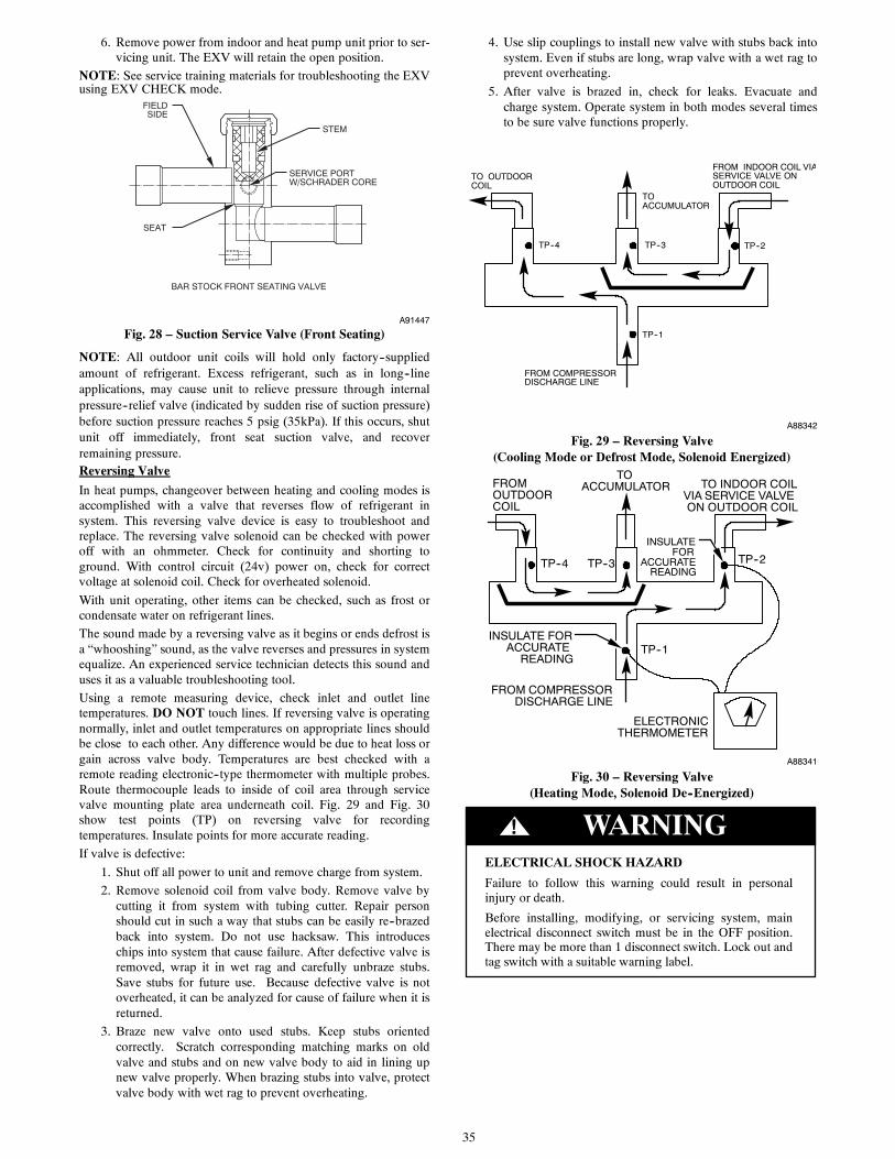
35
6. Remove power from indoor and heat pump unit prior to ser-vicing unit. The EXV will retain the open position.
NOTE: See service training materials for troubleshooting the EXVusing EXV CHECK mode.
STEM
SERVICE PORTW/SCHRADER CORE
SEAT
BAR STOCK FRONT SEATING VALVE
FIELDSIDE
A91447
Fig. 28 – Suction Service Valve (Front Seating)
NOTE: All outdoor unit coils will hold only factory--suppliedamount of refrigerant. Excess refrigerant, such as in long--lineapplications, may cause unit to relieve pressure through internalpressure--relief valve (indicated by sudden rise of suction pressure)before suction pressure reaches 5 psig (35kPa). If this occurs, shutunit off immediately, front seat suction valve, and recoverremaining pressure.Reversing Valve
In heat pumps, changeover between heating and cooling modes isaccomplished with a valve that reverses flow of refrigerant insystem. This reversing valve device is easy to troubleshoot andreplace. The reversing valve solenoid can be checked with poweroff with an ohmmeter. Check for continuity and shorting toground. With control circuit (24v) power on, check for correctvoltage at solenoid coil. Check for overheated solenoid.
With unit operating, other items can be checked, such as frost orcondensate water on refrigerant lines.
The sound made by a reversing valve as it begins or ends defrost isa “whooshing” sound, as the valve reverses and pressures in systemequalize. An experienced service technician detects this sound anduses it as a valuable troubleshooting tool.
Using a remote measuring device, check inlet and outlet linetemperatures. DO NOT touch lines. If reversing valve is operatingnormally, inlet and outlet temperatures on appropriate lines shouldbe close to each other. Any difference would be due to heat loss orgain across valve body. Temperatures are best checked with aremote reading electronic--type thermometer with multiple probes.Route thermocouple leads to inside of coil area through servicevalve mounting plate area underneath coil. Fig. 29 and Fig. 30show test points (TP) on reversing valve for recordingtemperatures. Insulate points for more accurate reading.
If valve is defective:
1. Shut off all power to unit and remove charge from system.
2. Remove solenoid coil from valve body. Remove valve bycutting it from system with tubing cutter. Repair personshould cut in such a way that stubs can be easily re--brazedback into system. Do not use hacksaw. This introduceschips into system that cause failure. After defective valve isremoved, wrap it in wet rag and carefully unbraze stubs.Save stubs for future use. Because defective valve is notoverheated, it can be analyzed for cause of failure when it isreturned.
3. Braze new valve onto used stubs. Keep stubs orientedcorrectly. Scratch corresponding matching marks on oldvalve and stubs and on new valve body to aid in lining upnew valve properly. When brazing stubs into valve, protectvalve body with wet rag to prevent overheating.
4. Use slip couplings to install new valve with stubs back intosystem. Even if stubs are long, wrap valve with a wet rag toprevent overheating.
5. After valve is brazed in, check for leaks. Evacuate andcharge system. Operate system in both modes several timesto be sure valve functions properly.
FROM INDOOR COIL VIASERVICE VALVE ONOUTDOOR COIL
TOACCUMULATOR
TO OUTDOORCOIL
TP--4 TP--3 TP--2
TP--1
FROM COMPRESSORDISCHARGE LINE
A88342
Fig. 29 – Reversing Valve(Cooling Mode or Defrost Mode, Solenoid Energized)
TO INDOOR COILVIA SERVICE VALVEON OUTDOOR COIL
TOACCUMULATOR
INSULATEFOR
ACCURATEREADING
FROMOUTDOORCOIL
TP--4 TP--3 TP--2
TP--1INSULATE FOR
ACCURATEREADING
FROM COMPRESSORDISCHARGE LINE
ELECTRONICTHERMOMETER
A88341
Fig. 30 – Reversing Valve(Heating Mode, Solenoid De--Energized)
! WARNINGELECTRICAL SHOCK HAZARD
Failure to follow this warning could result in personalinjury or death.
Before installing, modifying, or servicing system, mainelectrical disconnect switch must be in the OFF position.There may be more than 1 disconnect switch. Lock out andtag switch with a suitable warning label.
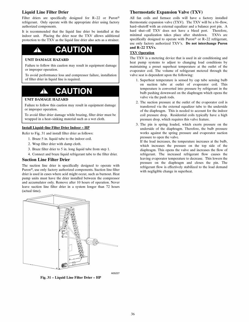
36
Liquid Line Filter DrierFilter driers are specifically designed for R--22 or Puronrrefrigerant. Only operate with the appropriate drier using factoryauthorized components.
It is recommended that the liquid line drier be installed at theindoor unit. Placing the drier near the TXV allows additionalprotection to the TXV as the liquid line drier also acts as a strainer.
CAUTION!
UNIT DAMAGE HAZARD
Failure to follow this caution may result in equipment damageor improper operation.
To avoid performance loss and compressor failure, installationof filter drier in liquid line is required.
CAUTION!UNIT DAMAGE HAZARD
Failure to follow this caution may result in equipment damageor improper operation.
To avoid filter drier damage while brazing, filter drier must bewrapped in a heat--sinking material such as a wet cloth.
Install Liquid--line Filter Drier Indoor -- HP
Refer to Fig. 31 and install filter drier as follows:
1. Braze 5 in. liquid tube to the indoor coil.
2. Wrap filter drier with damp cloth.
3. Braze filter drier to 5 in. long liquid tube from step 1.
4. Connect and braze liquid refrigerant tube to the filter drier.
Suction Line Filter DrierThe suction line drier is specifically designed to operate withPuronr, use only factory authorized components. Suction line filterdrier is used in cases where acid might occur, such as burnout. Heatpump units must have the drier installed between the compressorand accumulator only. Remove after 10 hours of operation. Neverleave suction line filter drier in a system longer than 72 hours(actual time).
A05227
Fig. 31 – Liquid Line Filter Drier -- HP
Thermostatic Expansion Valve (TXV)All fan coils and furnace coils will have a factory installedthermostatic expansion valve (TXV). The TXV will be a bi--flow,hard--shutoff with an external equalizer and a balance port pin. Ahard shut--off TXV does not have a bleed port. Therefore,minimal equalization takes place after shutdown. TXVs arespecifically designed to operate with Puronr or R--22 refrigerant,use only factory authorized TXV’s. Do not interchange Puronand R--22 TXVs.TXV Operation
The TXV is a metering device that is used in air conditioning andheat pump systems to adjust to changing load conditions bymaintaining a preset superheat temperature at the outlet of theevaporator coil. The volume of refrigerant metered through thevalve seat is dependent upon the following:
1. Superheat temperature is sensed by cap tube sensing bulbon suction tube at outlet of evaporator coil. Thistemperature is converted into pressure by refrigerant in thebulb pushing downward on the diaphragm which opens thevalve via the push rods.
2. The suction pressure at the outlet of the evaporator coil istransferred via the external equalizer tube to the undersideof the diaphragm. This is needed to account for the indoorcoil pressure drop. Residential coils typically have a highpressure drop, which requires this valve feature.
3. The pin is spring loaded, which exerts pressure on theunderside of the diaphragm. Therefore, the bulb pressureworks against the spring pressure and evaporator suctionpressure to open the valve.If the load increases, the temperature increases at the bulb,which increases the pressure on the top side of thediaphragm. This opens the valve and increases the flow ofrefrigerant. The increased refrigerant flow causes theleaving evaporator temperature to decrease. This lowers thepressure on the diaphragm and closes the pin. Therefrigerant flow is effectively stabilized to the load demandwith negligible change in superheat.
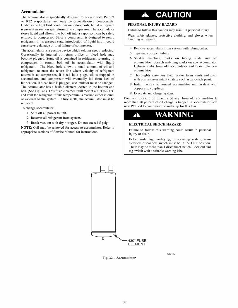
37
AccumulatorThe accumulator is specifically designed to operate with Puronror R22 respectfully; use only factory--authorized components.Under some light load conditions on indoor coils, liquid refrigerantis present in suction gas returning to compressor. The accumulatorstores liquid and allows it to boil off into a vapor so it can be safelyreturned to compressor. Since a compressor is designed to pumprefrigerant in its gaseous state, introduction of liquid into it couldcause severe damage or total failure of compressor.
The accumulator is a passive device which seldom needs replacing.Occasionally its internal oil return orifice or bleed hole maybecome plugged. Some oil is contained in refrigerant returning tocompressor. It cannot boil off in accumulator with liquidrefrigerant. The bleed hole allows a small amount of oil andrefrigerant to enter the return line where velocity of refrigerantreturns it to compressor. If bleed hole plugs, oil is trapped inaccumulator, and compressor will eventually fail from lack oflubrication. If bleed hole is plugged, accumulator must be changed.The accumulator has a fusible element located in the bottom endbell. (See Fig. 32.) This fusible element will melt at 430_F//221_Cand vent the refrigerant if this temperature is reached either internalor external to the system. If fuse melts, the accumulator must bereplaced.
To change accumulator:
1. Shut off all power to unit.
2. Recover all refrigerant from system.
3. Break vacuum with dry nitrogen. Do not exceed 5 psig.
NOTE: Coil may be removed for access to accumulator. Refer toappropriate sections of Service Manual for instructions.
PERSONAL INJURY HAZARD
Failure to follow this caution may result in personal injury.
Wear safety glasses, protective clothing, and gloves whenhandling refrigerant.
CAUTION!
4. Remove accumulator from system with tubing cutter.
5. Tape ends of open tubing.
6. Scratch matching marks on tubing studs and oldaccumulator. Scratch matching marks on new accumulator.Unbraze stubs from old accumulator and braze into newaccumulator.
7. Thoroughly rinse any flux residue from joints and paintwith corrosion--resistant coating such as zinc--rich paint.
8. Install factory authorized accumulator into system withcopper slip couplings.
9. Evacuate and charge system.
Pour and measure oil quantity (if any) from old accumulator. Ifmore than 20 percent of oil charge is trapped in accumulator, addnew POE oil to compressor to make up for this loss.
! WARNINGELECTRICAL SHOCK HAZARD
Failure to follow this warning could result in personalinjury or death.
Before installing, modifying, or servicing system, mainelectrical disconnect switch must be in the OFF position.There may be more than 1 disconnect switch. Lock out andtag switch with a suitable warning label.
430° FUSEELEMENT
A88410
Fig. 32 – Accumulator
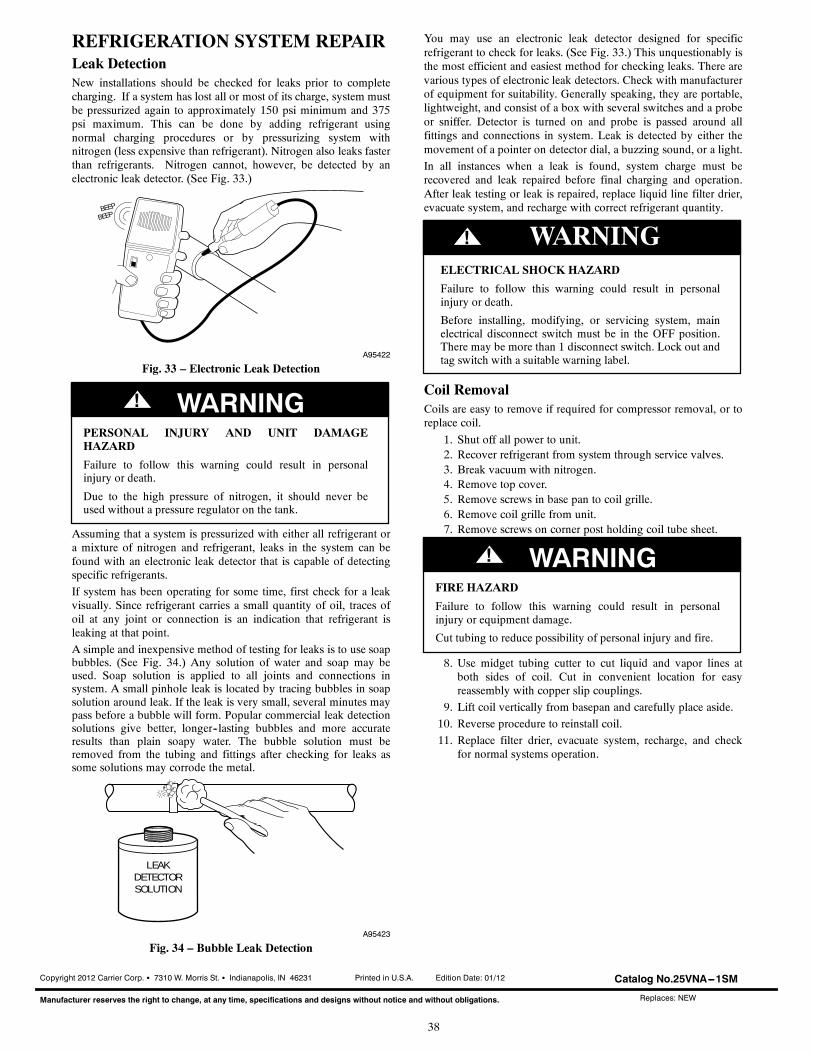
38
REFRIGERATION SYSTEM REPAIRLeak DetectionNew installations should be checked for leaks prior to completecharging. If a system has lost all or most of its charge, system mustbe pressurized again to approximately 150 psi minimum and 375psi maximum. This can be done by adding refrigerant usingnormal charging procedures or by pressurizing system withnitrogen (less expensive than refrigerant). Nitrogen also leaks fasterthan refrigerants. Nitrogen cannot, however, be detected by anelectronic leak detector. (See Fig. 33.)
BEEP
BEEP
A95422
Fig. 33 – Electronic Leak Detection
PERSONAL INJURY AND UNIT DAMAGEHAZARD
Failure to follow this warning could result in personalinjury or death.
Due to the high pressure of nitrogen, it should never beused without a pressure regulator on the tank.
! WARNING
Assuming that a system is pressurized with either all refrigerant ora mixture of nitrogen and refrigerant, leaks in the system can befound with an electronic leak detector that is capable of detectingspecific refrigerants.
If system has been operating for some time, first check for a leakvisually. Since refrigerant carries a small quantity of oil, traces ofoil at any joint or connection is an indication that refrigerant isleaking at that point.
A simple and inexpensive method of testing for leaks is to use soapbubbles. (See Fig. 34.) Any solution of water and soap may beused. Soap solution is applied to all joints and connections insystem. A small pinhole leak is located by tracing bubbles in soapsolution around leak. If the leak is very small, several minutes maypass before a bubble will form. Popular commercial leak detectionsolutions give better, longer--lasting bubbles and more accurateresults than plain soapy water. The bubble solution must beremoved from the tubing and fittings after checking for leaks assome solutions may corrode the metal.
LEAKDETECTORSOLUTION
A95423
Fig. 34 – Bubble Leak Detection
You may use an electronic leak detector designed for specificrefrigerant to check for leaks. (See Fig. 33.) This unquestionably isthe most efficient and easiest method for checking leaks. There arevarious types of electronic leak detectors. Check with manufacturerof equipment for suitability. Generally speaking, they are portable,lightweight, and consist of a box with several switches and a probeor sniffer. Detector is turned on and probe is passed around allfittings and connections in system. Leak is detected by either themovement of a pointer on detector dial, a buzzing sound, or a light.
In all instances when a leak is found, system charge must berecovered and leak repaired before final charging and operation.After leak testing or leak is repaired, replace liquid line filter drier,evacuate system, and recharge with correct refrigerant quantity.
! WARNINGELECTRICAL SHOCK HAZARD
Failure to follow this warning could result in personalinjury or death.
Before installing, modifying, or servicing system, mainelectrical disconnect switch must be in the OFF position.There may be more than 1 disconnect switch. Lock out andtag switch with a suitable warning label.
Coil RemovalCoils are easy to remove if required for compressor removal, or toreplace coil.
1. Shut off all power to unit.2. Recover refrigerant from system through service valves.3. Break vacuum with nitrogen.4. Remove top cover.5. Remove screws in base pan to coil grille.6. Remove coil grille from unit.7. Remove screws on corner post holding coil tube sheet.
FIRE HAZARD
Failure to follow this warning could result in personalinjury or equipment damage.
Cut tubing to reduce possibility of personal injury and fire.
! WARNING
8. Use midget tubing cutter to cut liquid and vapor lines atboth sides of coil. Cut in convenient location for easyreassembly with copper slip couplings.
9. Lift coil vertically from basepan and carefully place aside.
10. Reverse procedure to reinstall coil.
11. Replace filter drier, evacuate system, recharge, and checkfor normal systems operation.
Copyright 2012 Carrier Corp. S 7310 W. Morris St. S Indianapolis, IN 46231
Manufacturer reserves the right to change, at any time, specifications and designs without notice and without obligations.
Catalog No.25VNA---1SM
Replaces: NEW
Printed in U.S.A. Edition Date: 01/12