Embed Size (px)
Citation preview
INCompression / modeling with glassBrent Vander Werf, University of Arizona
...smooth space is constantly being translated, transversed into a sriated space; striated space is constantly being reversed, returned to a smooth space. In the first case, one organizes even the desert; in the second, the desert gains and grows; and the two can happen simultaneously.
Gilles Deleuze, A Thousand Plateaus 1
The masterwork is unknown; only the work is known, knowable...The work is made of forms, the masterwork is a formless fount of forms, the work is made of time, the masterwork is the source of times, the work is a confident chord, the masterwork trembles with noise...
Michel Serres, Genesis 2
Abstract:
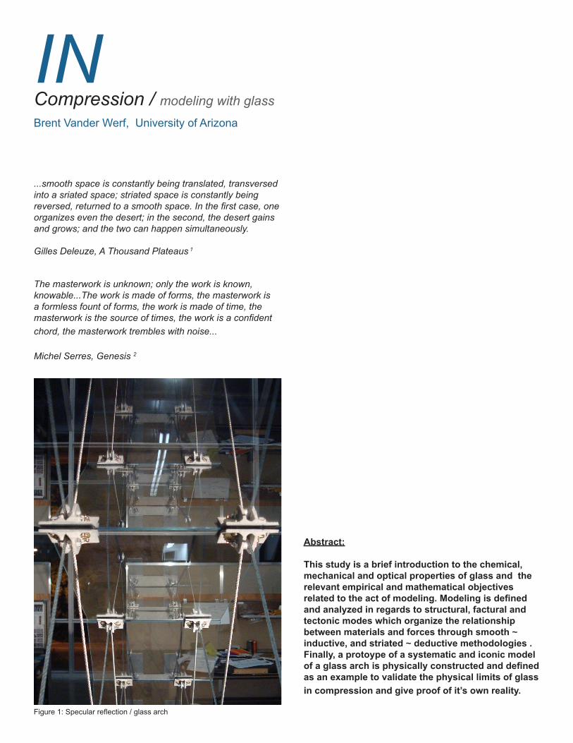
This study is a brief introduction to the chemical, mechanical and optical properties of glass and the relevant empirical and mathematical objectives related to the act of modeling. Modeling is defined and analyzed in regards to structural, factural and tectonic modes which organize the relationship between materials and forces through smooth ~ inductive, and striated ~ deductive methodologies . Finally, a protoype of a systematic and iconic model of a glass arch is physically constructed and defined as an example to validate the physical limits of glass in compression and give proof of it’s own reality.
Figure 1: Specular reflection / glass arch
Vander Werf 02
Glass /
Formation Properties:
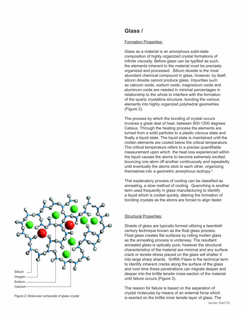
Glass as a material is an amorphous solid-state composition of highly organized crystal formations of infinite viscosity. Before glass can be typified as such, the elements inherent to the material must be precisely organized and processed. Silicon dioxide is the most abundant chemical compound in glass, however, by itself, silicon dioxide cannot produce glass. Impurities such as calcium oxide, sodium oxide, magnesium oxide and aluminum oxide are needed in minimal percentages in relationship to the whole to interfere with the formation of the quartz crystalline structure, bonding the various elements into highly organized polyhedral geometries (Figure 2).
The process by which the bonding of crystal occurs involves a great deal of heat, between 800-1200 degrees Celsius. Through the heating process the elements are turned from a solid particles to a plastic viscous state and finally a liquid state. The liquid state is maintained until the molten elements are cooled below the critical temperature. The critical temperature refers to a precise quantifiable measurement upon which the heat loss experienced within the liquid causes the atoms to become extremely excited, bouncing one atom off another continuously and repeatedly until eventually the atoms stick to each other, organizing themselves into a geometric amorphous isotropy 3.
This explanatory process of cooling can be classified as annealing, a slow method of cooling. Quenching is another term used frequently in glass manufacturing to identify a liquid which is cooled quickly, altering the formation of bonding crystals as the atoms are forced to align faster.
Structural Properties:
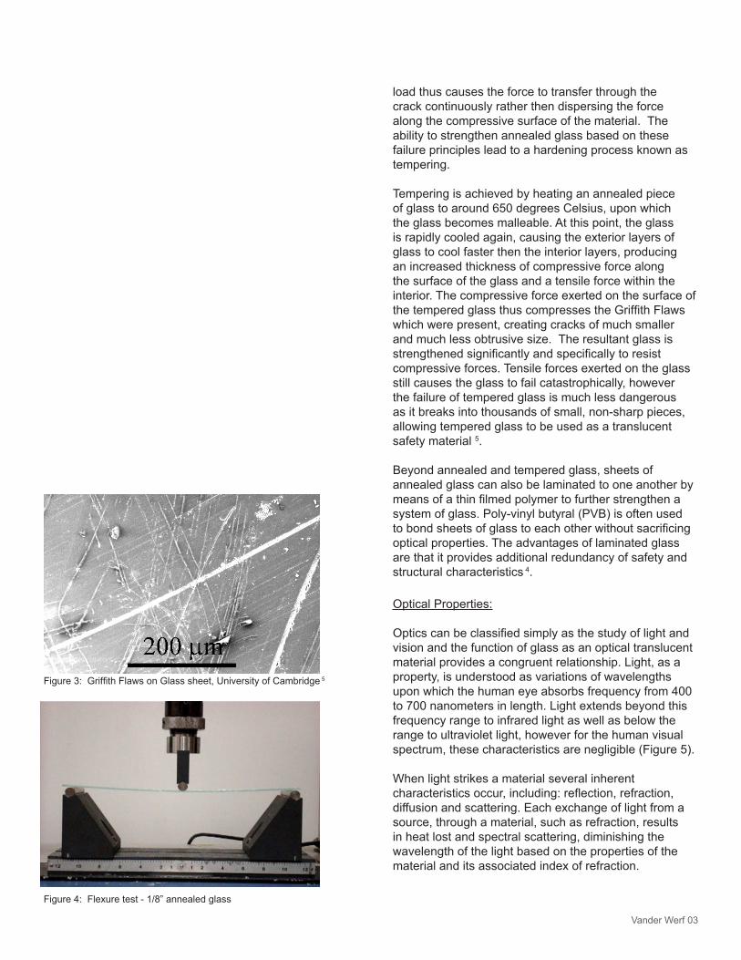
Sheets of glass are typically formed utilizing a twentieth century technique known as the float glass process. Float glass creates flat surfaces by rolling molten glass as the annealing process is underway. The resultant annealed glass is optically pure, however the structural characteristics of the material are minimal and any surface crack or tensile stress placed on the glass will shatter it into large sharp shards. Griffith Flaws is the technical term to identify inherent cracks along the surface of the glass and over time these penetrations can migrate deeper and deeper into the brittle tensile cross-section of the material until failure occurs (Figure 3).
The reason for failure is based on the separation of crystal molecules by means of an external force which is exerted on the brittle inner tensile layer of glass. The
SiliconOxygenSodiumCalcium
Figure 2: Molecular composite of glass crystal
Vander Werf 03
load thus causes the force to transfer through the crack continuously rather then dispersing the force along the compressive surface of the material. The ability to strengthen annealed glass based on these failure principles lead to a hardening process known as tempering.
Tempering is achieved by heating an annealed piece of glass to around 650 degrees Celsius, upon which the glass becomes malleable. At this point, the glass is rapidly cooled again, causing the exterior layers of glass to cool faster then the interior layers, producing an increased thickness of compressive force along the surface of the glass and a tensile force within the interior. The compressive force exerted on the surface of the tempered glass thus compresses the Griffith Flaws which were present, creating cracks of much smaller and much less obtrusive size. The resultant glass is strengthened significantly and specifically to resist compressive forces. Tensile forces exerted on the glass still causes the glass to fail catastrophically, however the failure of tempered glass is much less dangerous as it breaks into thousands of small, non-sharp pieces, allowing tempered glass to be used as a translucent safety material 5.
Beyond annealed and tempered glass, sheets of annealed glass can also be laminated to one another by means of a thin filmed polymer to further strengthen a system of glass. Poly-vinyl butyral (PVB) is often used to bond sheets of glass to each other without sacrificing optical properties. The advantages of laminated glass are that it provides additional redundancy of safety and structural characteristics 4.
Optical Properties:
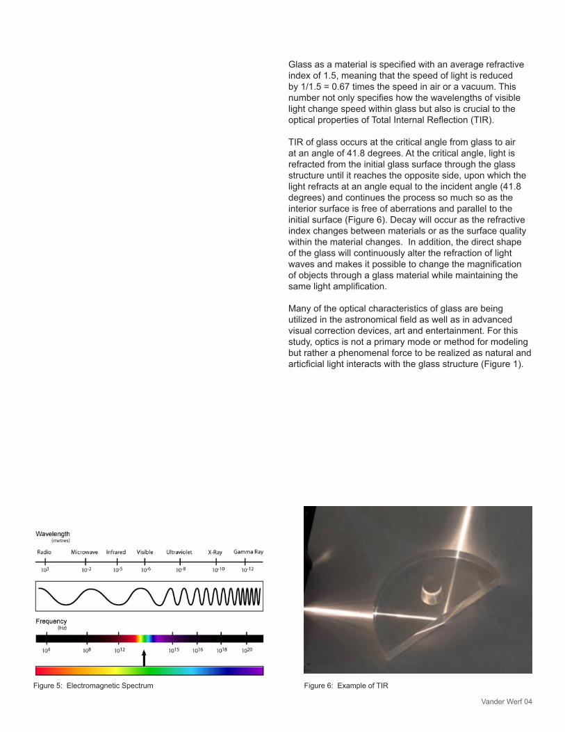
Optics can be classified simply as the study of light and vision and the function of glass as an optical translucent material provides a congruent relationship. Light, as a property, is understood as variations of wavelengths upon which the human eye absorbs frequency from 400 to 700 nanometers in length. Light extends beyond this frequency range to infrared light as well as below the range to ultraviolet light, however for the human visual spectrum, these characteristics are negligible (Figure 5).
When light strikes a material several inherent characteristics occur, including: reflection, refraction, diffusion and scattering. Each exchange of light from a source, through a material, such as refraction, results in heat lost and spectral scattering, diminishing the wavelength of the light based on the properties of the material and its associated index of refraction.
Figure 4: Flexure test - 1/8” annealed glass
Figure 3: Griffith Flaws on Glass sheet, University of Cambridge 5
Vander Werf 04
Figure 5: Electromagnetic Spectrum
Glass as a material is specified with an average refractive index of 1.5, meaning that the speed of light is reduced by 1/1.5 = 0.67 times the speed in air or a vacuum. This number not only specifies how the wavelengths of visible light change speed within glass but also is crucial to the optical properties of Total Internal Reflection (TIR).
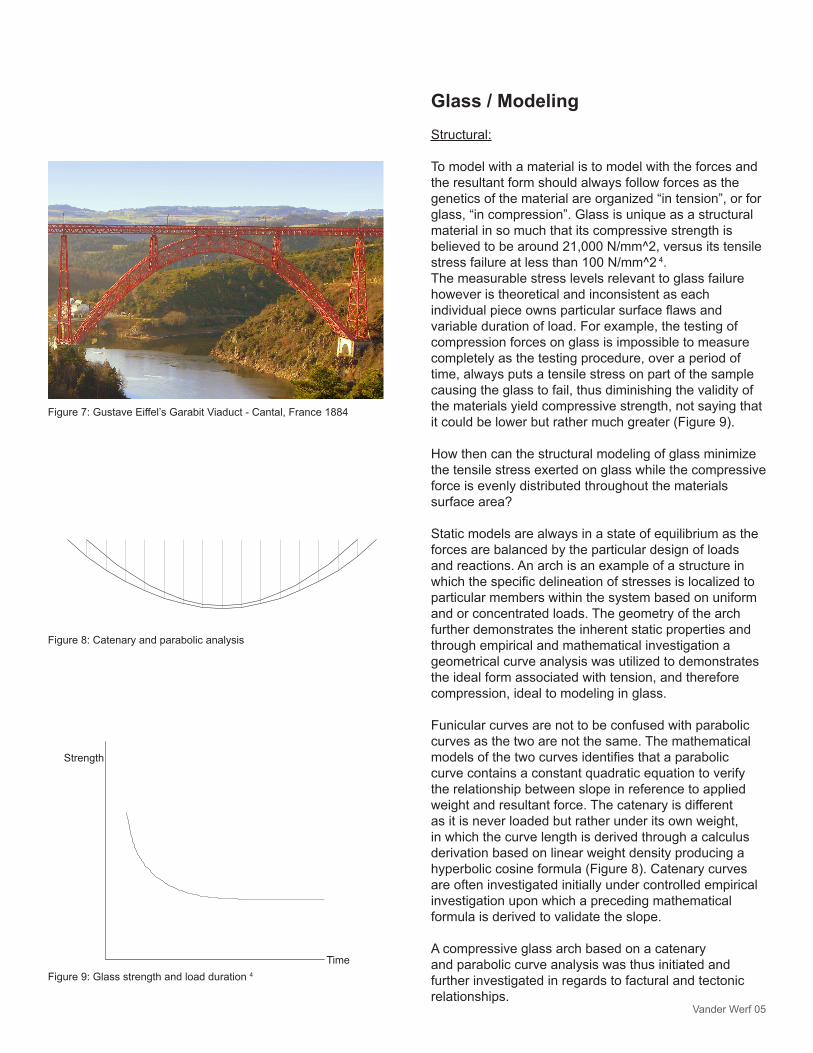
TIR of glass occurs at the critical angle from glass to air at an angle of 41.8 degrees. At the critical angle, light is refracted from the initial glass surface through the glass structure until it reaches the opposite side, upon which the light refracts at an angle equal to the incident angle (41.8 degrees) and continues the process so much so as the interior surface is free of aberrations and parallel to the initial surface (Figure 6). Decay will occur as the refractive index changes between materials or as the surface quality within the material changes. In addition, the direct shape of the glass will continuously alter the refraction of light waves and makes it possible to change the magnification of objects through a glass material while maintaining the same light amplification.
Many of the optical characteristics of glass are being utilized in the astronomical field as well as in advanced visual correction devices, art and entertainment. For this study, optics is not a primary mode or method for modeling but rather a phenomenal force to be realized as natural and articficial light interacts with the glass structure (Figure 1).
Figure 6: Example of TIR
Vander Werf 05
Glass / Modeling Structural:
To model with a material is to model with the forces and the resultant form should always follow forces as the genetics of the material are organized “in tension”, or for glass, “in compression”. Glass is unique as a structural material in so much that its compressive strength is believed to be around 21,000 N/mm^2, versus its tensile stress failure at less than 100 N/mm^2 4. The measurable stress levels relevant to glass failure however is theoretical and inconsistent as each individual piece owns particular surface flaws and variable duration of load. For example, the testing of compression forces on glass is impossible to measure completely as the testing procedure, over a period of time, always puts a tensile stress on part of the sample causing the glass to fail, thus diminishing the validity of the materials yield compressive strength, not saying that it could be lower but rather much greater (Figure 9).
How then can the structural modeling of glass minimize the tensile stress exerted on glass while the compressive force is evenly distributed throughout the materials surface area?
Static models are always in a state of equilibrium as the forces are balanced by the particular design of loads and reactions. An arch is an example of a structure in which the specific delineation of stresses is localized to particular members within the system based on uniform and or concentrated loads. The geometry of the arch further demonstrates the inherent static properties and through empirical and mathematical investigation a geometrical curve analysis was utilized to demonstrates the ideal form associated with tension, and therefore compression, ideal to modeling in glass.
Funicular curves are not to be confused with parabolic curves as the two are not the same. The mathematical models of the two curves identifies that a parabolic curve contains a constant quadratic equation to verify the relationship between slope in reference to applied weight and resultant force. The catenary is different as it is never loaded but rather under its own weight, in which the curve length is derived through a calculus derivation based on linear weight density producing a hyperbolic cosine formula (Figure 8). Catenary curves are often investigated initially under controlled empirical investigation upon which a preceding mathematical formula is derived to validate the slope.
A compressive glass arch based on a catenary and parabolic curve analysis was thus initiated and further investigated in regards to factural and tectonic relationships.
Figure 8: Catenary and parabolic analysis
Figure 7: Gustave Eiffel’s Garabit Viaduct - Cantal, France 1884
Figure 9: Glass strength and load duration 4
Strength
Time
Vander Werf 06
Factural:
The compressive capacity of glass as a material established a shaping logic focused on functional characteristics of the arch with a complementary secondary material, steel, to order the tensile forces required for equilibrium. The interplay of these materials is directly and indirectly related to the inherent chemical structuring of each material, glass being amorphous and steel being crystalline.
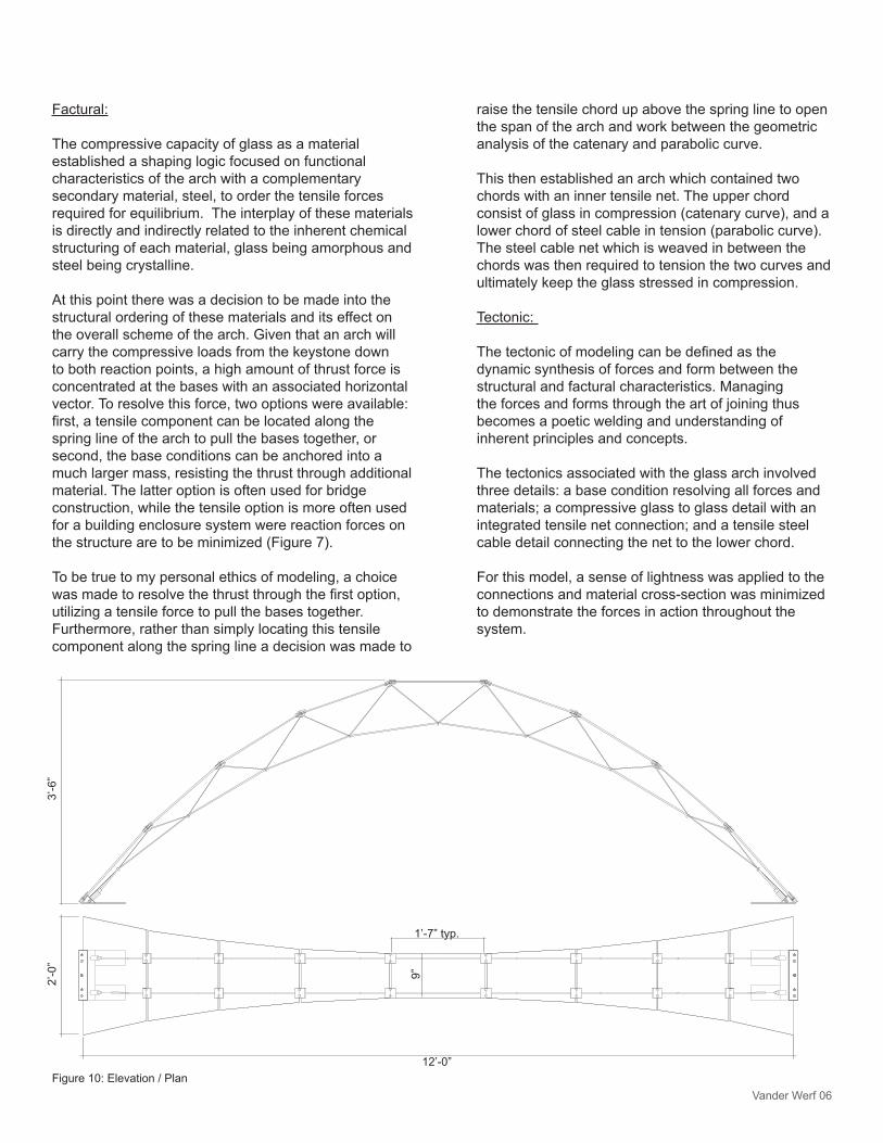
At this point there was a decision to be made into the structural ordering of these materials and its effect on the overall scheme of the arch. Given that an arch will carry the compressive loads from the keystone down to both reaction points, a high amount of thrust force is concentrated at the bases with an associated horizontal vector. To resolve this force, two options were available: first, a tensile component can be located along the spring line of the arch to pull the bases together, or second, the base conditions can be anchored into a much larger mass, resisting the thrust through additional material. The latter option is often used for bridge construction, while the tensile option is more often used for a building enclosure system were reaction forces on the structure are to be minimized (Figure 7).
To be true to my personal ethics of modeling, a choice was made to resolve the thrust through the first option, utilizing a tensile force to pull the bases together. Furthermore, rather than simply locating this tensile component along the spring line a decision was made to
12’-0”
3’-6
”2’
-0”
9”
1’-7” typ.
Figure 10: Elevation / Plan
raise the tensile chord up above the spring line to open the span of the arch and work between the geometric analysis of the catenary and parabolic curve. This then established an arch which contained two chords with an inner tensile net. The upper chord consist of glass in compression (catenary curve), and a lower chord of steel cable in tension (parabolic curve). The steel cable net which is weaved in between the chords was then required to tension the two curves and ultimately keep the glass stressed in compression.
Tectonic:
The tectonic of modeling can be defined as the dynamic synthesis of forces and form between the structural and factural characteristics. Managing the forces and forms through the art of joining thus becomes a poetic welding and understanding of inherent principles and concepts.
The tectonics associated with the glass arch involved three details: a base condition resolving all forces and materials; a compressive glass to glass detail with an integrated tensile net connection; and a tensile steel cable detail connecting the net to the lower chord.
For this model, a sense of lightness was applied to the connections and material cross-section was minimized to demonstrate the forces in action throughout the system.
Vander Werf 07
Glass / Prototype Glass Arch:
A prototype is the physical organization of materials and forces upon which a functional form of a new type is created. The performance of the prototype is required in modeling to fulfill the claim and execution of action within a proto - “first”, type “species”.
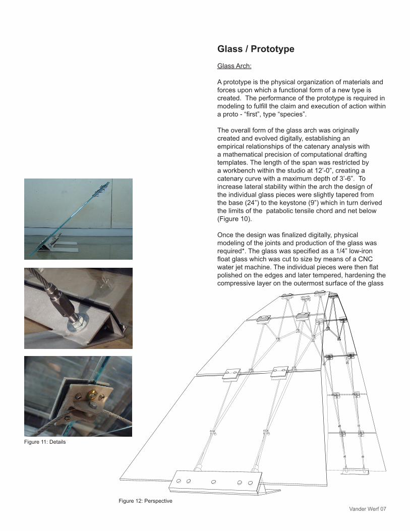
The overall form of the glass arch was originally created and evolved digitally, establishing an empirical relationships of the catenary analysis with a mathematical precision of computational drafting templates. The length of the span was restricted by a workbench within the studio at 12’-0”, creating a catenary curve with a maximum depth of 3’-6”. To increase lateral stability within the arch the design of the individual glass pieces were slightly tapered from the base (24”) to the keystone (9”) which in turn derived the limits of the patabolic tensile chord and net below (Figure 10).
Once the design was finalized digitally, physical modeling of the joints and production of the glass was required*. The glass was specified as a 1/4” low-iron float glass which was cut to size by means of a CNC water jet machine. The individual pieces were then flat polished on the edges and later tempered, hardening the compressive layer on the outermost surface of the glass
Figure 12: Perspective
Figure 11: Details
Vander Werf 08
minimizing the probability of stress failures associated with surface flaws.
While the glass was being produced the individual clamping details, base details and tensile steel cable connectors were manufactured. Utilizing the steel manufacturing laboratory at the University of Arizona’s Architecture College, the aluminum alloy pieces were break pressed, drilled, TIG welded and finally sand blasted. 16 glass to glass details and two base details were manufactured over a week’s time. The tensile chord connections were ordered online as a self-swage detail and designed to resolve appropriately within the base detail. Additionally, the tensile net connections were pre-ordered as U-clamps to secure the net to the lower chord upon installation. The final designed utilized 1/4” steel cable for the lower chord and 1/8” steel cable for the tensile net (Figure 11).
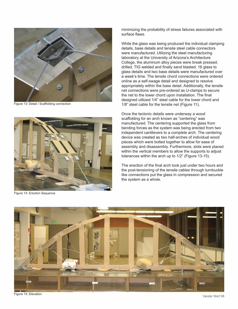
Once the tectonic details were underway a wood scaffolding for an arch known as “centering” was manufactured. The centering supported the glass from bending forces as the system was being erected from two independent cantilevers to a complete arch. The centering device was created as two half-arches of individual wood pieces which were bolted together to allow for ease of assembly and disassembly. Furthermore, slots were placed within the vertical members to allow the supports to adjust tolerances within the arch up to 1/2” (Figure 13-15).
The erection of the final arch took just under two hours and the post-tensioning of the tensile cables through turnbuckle like connections put the glass in compression and secured the system as a whole.
Figure 13: Detail / Scaffolding connection
Figure 14: Erection Sequence
Figure 15: Elevation
Vander Werf 09
Evaluation:
The functional aspect of the structure as a whole is an objective evaluation which the model validates in that the ordering and relationships between parts and forces was resolved in equilibrium. There was slight difficulty in properly post-tensioning the arch through the multiple tensile cable, leading to an overall structure which was semi-flexible. This flexure could be alleviated in the future however by adjusting the termination of the steel cable to the base detail and determining the appropriate stress required and applied under the post-tensioning sequence.
The use of the arch is less specific then the function however and is subjective in relationship to an external agenda. The optical, weatherproofing, acoustic and thermal forces are unresolved as the use is particular and undefined. The arch is rather a systematic or instrumental model of physical limits, modeling the glass with the forces.
Finally, there is a unique personal and physical affection that is placed on the object as its maintains the ability to create a free play of the five senses; sight, sound, taste, touch and smell.. The glass arch is thus a systematic model as well as a physiognomic or iconic model upon which the care for the object creates an affective relationship, further increasing the models validity of action.
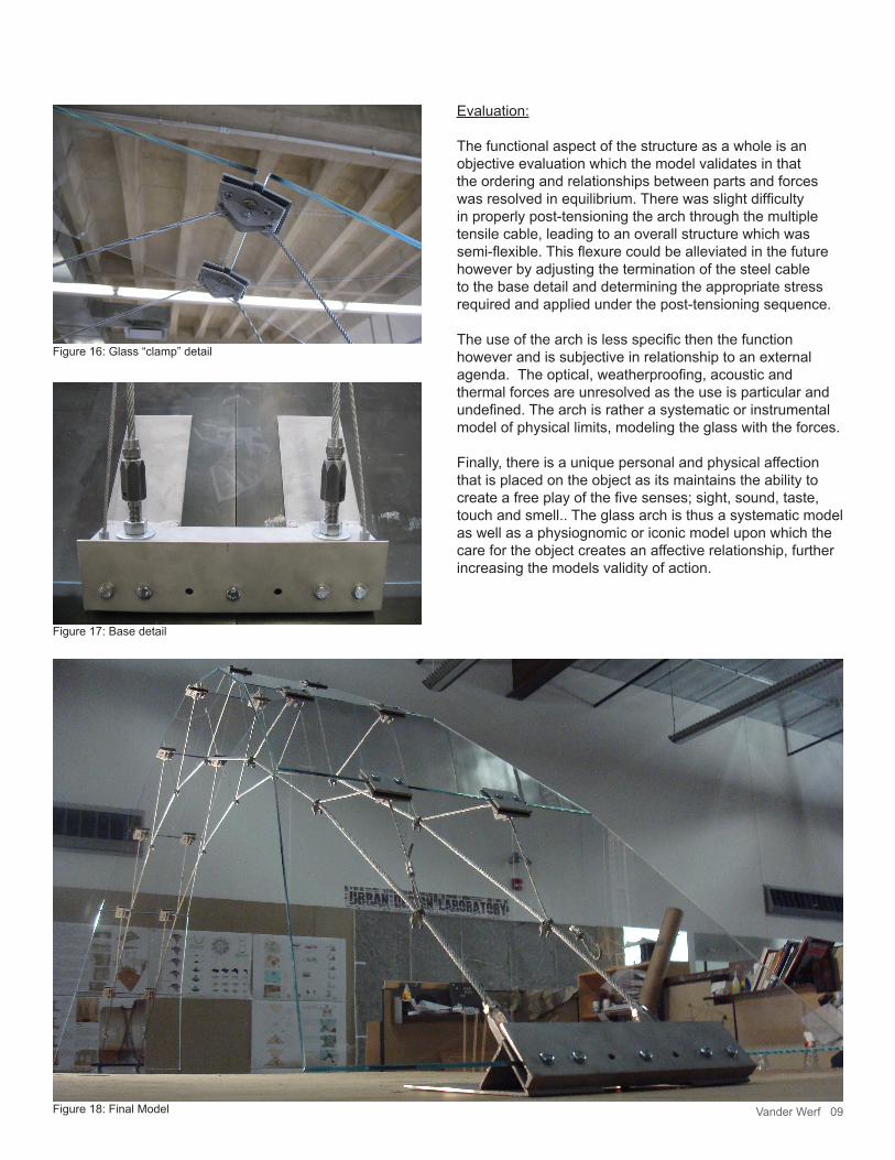
Figure 16: Glass “clamp” detail
Figure 17: Base detail
Figure 18: Final Model
Vander Werf 10
References:
1. Deleuze, Gilles. Mille Plateaux. English; A Thousand Plateaus: Capitalism and Schizophrenia / Gilles Deleuze, Félix Guattari; Translation and Foreword by Brian Massumi. Ed. Félix Guattari. Minneapolis: University of Minnesota Press, c1987.
2. Serres, Michel. Genèse. English; Genesis / Michel Serres; Translated by Geneviève James and James Nielson. Ann Arbor: University of Michigan Press, c1995.
3.Glass Construction Manual / Christian Schittich. Ed. Christian Schittich and DETAIL. Rev. ed. ed. Basel: London: Birkhäuser; Springer [distributor], 2007.
4. Glass in Building : A Guide to Modern Architectural Glass Performance / David Button.; Editors: David Button and Brian Pye. Ed. David Button, Brian Pye, and Ltd Pilkington Brothers. Oxford: Pilkington with Butterworth Architecture, c1993.
5. “University of Cambridge, Material Selection and Processing.” 2002. <http://www-materials.eng.cam. ac.uk.ezproxy1.library.arizona.edu/mpsite/default. html.
*Acknowledgement: Thanks to an inspirational dialogue with Alex Miramontez, the vice-president of the local glass distributor GlazTech Industries, complementary aid in the cost and production of glass was alleviated.