Embed Size (px)
Citation preview

Effectivity: 912 Series
MAINTENANCE MANUALAIRCRAFT ENGINES
d011
96
00-00-00page 13
Rev. 1, Jan. 01/2002
This information relates to the preparation and use of ROTAX® aircraft engines and hasbeen utilized safely and effectively by ROTAX®. However, ROTAX® disclaims liabilityfor all damage and/or injuries resulting from the improper use of the contents. Westrongly recommend that any service be carried out and/or verified by a highly skilledprofessional mechanic, see chapter 05-00-00, para 2.2.
Specifications are given in the SI metric system with the USA equivalent in parenthesis.Where precise accuracy is not required, some conversions are rounded off for easieruse.
Because of our ongoing commitment to product quality and innovation. ROTAX®
reserves the right at any time, and without incuring obligation, to remove, replace ordiscontinue any design, specification, feature or otherwise.

MAINTENANCE MANUALAIRCRAFT ENGINES
00-00-00page 14
Rev. 3, October 01/2005
Effectivity: 912 Series
d036
19
5.1) Repeating symbolsThis Manual uses the following symbols to emphasize particular information:
▲ WARNING: Identifies an instruction which, if not followed, may causeserious injury including the possibility of death.
■ CAUTION: Denotes an instruction which, if not followed, may severelydamage the engine or other component.
◆ NOTE: Indicates supplementary information which may be neededto fully complete or understand an instruction.
5.2) Maintenance ConceptThe maintenance functions detailed in this manual fall into two categories:Maintenance I (Line Maintenance) and Maintenance II (Heavy Maintenance).
Repairs beyond the levels detailed in this manual are not recommended asmaintenance functions and must be done by an authorized overhaul facility.
- Maintenance I (Line Maintenance) (Chapter 00, 05 and 12):
The scope of line maintenance consists of removal, installation and adjustmentof engine components (including part wear). All procedures in this manualare to be considered line maintenance.
◆ NOTE: On procedures beyond the capabilities of Line Maintenance,is referred to the Heavy Maintenance Manual if necessary.
- Maintenance II (Heavy Maintenance) (separate Manual p/n 899601):
Maintenance II details removal, installation and repair of components or partsnormally considered beyond the capabilities of the “Line maintenance”.
This manual can only be used in combination with Maintenance manual I(Line Maintenance), as it builds up on it.

Effectivity: 912 Series
MAINTENANCE MANUALAIRCRAFT ENGINES
d036
19
00-00-00page 15
Rev. 3, October 01/2005
5.3) Technical documentationThese documents form the instructions for continued airworthiness of ROTAX®
aircraft engines:
- Installation Manual 912 F- Installation Manual 912 A- Installation Manual 912 UL- Installation Manual 912 S- Maintenance Manual 912 Series (Line+Heavy MM)- Operators Manual 912 Series- Illustrated Parts Catalogue 912 A / F / S / UL / ULS, 914 F / UL- Overhaul Manual 912 A / F- Alert Service Bulletins- Service Bulletins- Service Instructions- Service Letters
Any reference to a document refers to the latest edition issued by ROTAX® , if not
stated otherwise.
The rapid technical progress and variations of installation might render presentlaws and regulations inapplicable or inadequate.
The illustrations in this Manual are mere sketches and show a typical arrange-ment. They may not represent the actual part in all its details but depict parts ofthe same or similar function. Therefore deduction of dimensions or other detailsfrom illustrations is not permitted.
- All necessary documentation is available from the ROTAX® Distribution- andService Centers.
- The current documentation is available on SB-912-000 and on the officialhomepage www.rotax-aircraft-engines.com.Most of the necessary documents are also available as pdf-files. Downloadis free of charge.
◆ NOTE: The Illustrations and Documents in this Manual are stored in adocument data file/graphic data file and are provided with aconsecutive irrelevant number.
This number (e.g. 00277) is of no significance for the content.
Return shipment:
If necessary to return an engine or components like gearbox ect. to an authorizedoverhaul or repair facility, all required documents (Log book, Maintenance logetc.) has to be included on that shipment.

MAINTENANCE MANUALAIRCRAFT ENGINES
00-00-00page 16
Rev. 1, Jan. 01/2002
Effectivity: 912 Series
d011
96
5.3.1) Use for intended purpose- The engine ROTAX® 912 A/F/S is intended for use in certified
aircraft. In case of doubt the regulations of the national authorities orthe respective aviation federations must be observed.
- The certified aircraft engine 912 models A/F/S are tested as peraeronautical standards for safety and time between overhaul. It wasdeveloped to the latest state of the art and intensively tested.
◆ NOTE: The 912 engine models UL/ULS are not certified en-gines. These engines have not received any aeronau-tical standards or regulatory safety or durability testing,and conform to no aircraft standards. These enginesare for use in experimental, uncertificated aircraft andvehicles only in which an engine failure will not com-promise safety. However these engines confirm toROTAX
® quality standards.
The operator assumes all risk of use, and acknowl-edges by this use that he/she knows this engine issubject to sudden stoppage.
- Use for intended purpose also means respecting the prescribedoperational- maintenance- and repair conditions. This also increasesthe engine time between overhaul efficiency.
▲ WARNING: Never run the engine without propeller, this inevitablycauses engine damage and is an explosion hazard.

Effectivity: 912 Series
MAINTENANCE MANUALAIRCRAFT ENGINES
d011
96
00-00-00page 17
Rev. 1, Jan. 01/2002
5.3.2) InstructionEngines require specific instructions regarding their application, opera-tion, maintenance and repair.
Technical documentation and directions are useful and necessarycomplementary elements for personal instruction, but can by no meanssubstitute theoretical and practical instructions. These instructionsshould cover explanation of the technical context, advice for operation,maintenance, use and operational safety of the engine.
- This engine must only be operated with accessories supplied,recommended and released by ROTAX
®. Modifications are only
allowed after consent by the engine manufacturer.
- After engine standstill (longer than 2 months) observe without failthe instructions for engine "out of use". Protect fuel- and carburetorsystem against contamination.
■ CAUTION: Spare parts must meet with the requirements definedby the engine manufacturer. This is only warranted byuse of GENUINE ROTAX® spare parts and/or accesso-ries (see IPC) or suitable equivalent in the manufactuer’sopinion otherwise, any limited warranty by ROTAX® isnull and void (see Warranty Conditions).
All Spare parts are available at the authorized ROTAX®
Distribution- and Service centers.

MAINTENANCE MANUALAIRCRAFT ENGINES
00-00-00page 18
Rev. 3, October 01/2005
Effectivity: 912 Series
d036
19
section page date section page date
02773
00-00-00 1 2002 01 012 2002 01 013 2002 01 014 2002 01 015 2002 01 016 2003 03 017 2003 03 018 2002 01 019 2002 01 01
10 2002 01 0111 2002 01 0112 2002 01 0113 2002 01 0114 2005 10 0115 2005 10 0116 2002 01 0117 2002 01 0118 2005 10 0119 2005 10 0120 2005 10 01
05-00-00 1 2002 01 012 2005 10 013 2002 01 014 2002 01 015 2002 01 016 2002 01 017 2002 01 018 2005 10 019 2005 10 01
10 2005 10 0111 2005 10 0112 2002 01 01
05-10-00 1 2002 01 012 2003 03 013 2005 10 014 2002 01 01
05-20-00 1 2003 03 012 2002 01 013 2002 01 014 2002 01 015 2002 01 016 2005 10 017 2005 10 018 2005 10 019 2005 10 01
10 2005 10 0111 2005 10 0112 2005 10 0113 2005 10 0114 2002 01 01
05-50-00 1 2002 01 012 2005 10 013 2005 10 014 2005 10 015 2005 10 016 2002 01 017 2002 01 018 2005 10 019 2005 10 01
10 2002 01 0111 2002 01 0112 2002 01 0113 2003 01 0114 2003 01 01
6) List of the current pages

Effectivity: 912 Series
MAINTENANCE MANUALAIRCRAFT ENGINES
d036
19
00-00-00page 19
Rev. 3, October 01/2005
02773
section page date section page date
12-00-00 1 2002 01 012 2003 03 013 2002 01 014 2002 01 015 2005 10 016 2002 01 017 2002 01 018 2002 01 019 2005 10 01
10 2002 01 0111 2003 03 0112 2002 01 0113 2002 01 0114 2002 01 0115 2002 01 0116 2005 10 0117 2003 03 0118 2003 03 0119 2002 01 0120 2003 03 0121 2003 03 0122 2003 03 0123 2002 01 0124 2002 01 0125 2002 01 0126 2003 03 0127 2005 10 0128 2005 10 0129 2005 10 0130 2003 03 0131 2002 01 0132 2002 01 0133 2002 01 0134 2002 01 0135 2003 03 0136 2002 01 0137 2002 01 0138 2005 10 0139 2002 01 0140 2002 01 0141 2005 10 0142 2005 10 01

MAINTENANCE MANUALAIRCRAFT ENGINES
00-00-00page 20
Rev. 3, October 01/2005
Effectivity: 912 Series
d036
19
date remark for date of dateno. section page of approval approval from of signature
change authorities issue
0 00-00-00 1 up to 22 98 09 01 not required 98 09 01 AA/HeC0 05-00-00 1 up to 12 98 09 01 not required 98 09 010 05-10-00 1 up to 4* 98 09 01 englisch version 98 09 01 AA/HeC0 05-20-00 1 up to 14* 98 09 01 not required 98 09 010 05-50-00 1 up to 12* 98 09 01 98 09 010 12-00-00 1 up to 36 98 09 01 not required 98 09 01 AA/HeC
1 00-00-00 1.2,4,6-8,10-20 2002 01 01 not required 2002 01 01 AA/HeC1 05-00-00 1 up to 6,8,11,12 2002 01 01 not required 2002 01 011 05-10-00 1 up to 4* 2002 01 01 englisch version 2002 01 01 AA/HeC1 05-20-00 1,2,4 up to 13,14* 2002 01 01 not required 2002 01 011 05-50-00 1up to 12* 2002 01 01 2002 01 011 12-00-00 1 up to 41 2002 01 01 not required2 00-00-00 7, 18, 19, 20 2003 03 01 not required2 05-00-00 2 2003 03 01 not required2 05-10-00 2, 3 2003 03 01 englisch version german
2 05-20-00 1, 8 2003 03 01 not required version
2 05-50-00 3, 5, 13, 14 2003 03 01 15.04.20032 12-00-00 9,11,17,18, 20-22, 2003 03 01 not required
26, 29, 30, 35, 423 00-00-00 14,15,18-20 2005 10 013 05-00-00 2,8-11 2005 10 013 05-10-00 3 2005 10 01 DOA **3 05-20-00 6-13 2005 10 013 05-50-00 2-5,8,9 2005 10 013 12-00-00 5,9,16,27-29,38, 2005 10 01
41,42
02774
7) Table of amendments
Approval **
The technical content is approved under the authority
of DOA Nr. EASA.21J.048.
* The note of approval of the Aviation Authority refers only to the certified engines of theType 912 A(TW 8/89), 912 F / S (TW9 - ACG).
Effectivity: 912 Series
MAINTENANCE MANUALAIRCRAFT ENGINES
d011
97
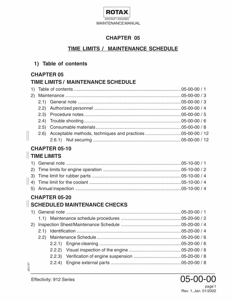
05-00-00page 1
Rev. 1, Jan. 01/2002
CHAPTER 05TIME LIMITS / MAINTENANCE SCHEDULE1) Table of contents .................................................................................... 05-00-00 / 12) Maintenance ...........................................................................................05-00-00 / 3
2.1) General note .................................................................................05-00-00 / 32.2) Authorized personnel ....................................................................05-00-00 / 42.3) Procedure notes ............................................................................05-00-00 / 52.4) Trouble shooting ............................................................................05-00-00 / 62.5) Consumable materials...................................................................05-00-00 / 82.6) Acceptable methods, techniques and practices ............................05-00-00 / 12
2.6.1) Nut securing .....................................................................05-00-00 / 12
CHAPTER 05-10TIME LIMITS1) General note ..........................................................................................05-10-00 / 12) Time limits for engine operation ............................................................. 05-10-00 / 23) Time limit for rubber parts ......................................................................05-10-00 / 44) Time limit for the coolant ........................................................................05-10-00 / 45) Annual inspection ...................................................................................05-10-00 / 4
CHAPTER 05-20SCHEDULED MAINTENANCE CHECKS1) General note ..........................................................................................05-20-00 / 1
1.1) Maintenance schedule procedures ...............................................05-20-00 / 22) Inspection Sheet/Maintenance Schedule ...............................................05-20-00 / 4
2.1) Identification ..................................................................................05-20-00 / 42.2) Maintenance Schedule ..................................................................05-20-00 / 6
2.2.1) Engine cleaning ................................................................ 05-20-00 / 62.2.2) Visual inspection of the engine ......................................... 05-20-00 / 62.2.3) Verification of engine suspension ..................................... 05-20-00 / 82.2.4) Engine external parts .......................................................05-20-00 / 8
CHAPTER 05
TIME LIMITS / MAINTENANCE SCHEDULE
1) Table of contents

MAINTENANCE MANUALAIRCRAFT ENGINES
Effectivity: 912 Series
d036
20
05-00-00page 2
Rev. 3, October 01/2005
2.2.5) Check of propeller gear box .............................................05-20-00 / 82.2.6) Oil level check...................................................................05-20-00 / 82.2.7) Oil change ........................................................................05-20-00 / 92.2.8) Cleaning of the cooling system.........................................05-20-00 / 102.2.9) Check of the air filter ........................................................05-20-00 / 102.2.10) Inspection of the carburetor sockets ................................05-20-00 / 112.2.11) Check of the carburetors ..................................................05-20-00 / 112.2.12) Verification of the V-belt tension ....................................... 05-20-00 / 122.2.13) Spark plugs ......................................................................05-20-00 / 122.2.14) Spark plug connectors ......................................................05-20-00 / 122.2.15) Check of compression ......................................................05-20-00 / 122.2.16) Engine test run .................................................................05-20-00 / 132.2.17) General note ....................................................................05-20-00 / 13
CHAPTER 05-50UNSCHEDULED MAINTENANCE CHECKS1) General note ..........................................................................................05-50-00 / 12) Special checks ........................................................................................05-50-00 / 2
2.1) Checking of propeller gearbox / engine. ........................................ 05-50-00 / 22.1.1) Propeller gearbox with integrated overload clutch ............ 05-50-00 / 22.1.2) Propeller gearbox without integrated overload clutch .......05-50-00 / 2
2.2) Checking of the overload clutch ....................................................05-50-00 / 32.3) Examination after engine failure ....................................................05-50-00 / 52.4) Engine back to operation after submerging in water .....................05-50-00 / 62.5) Checks in extreme climatic conditions...........................................05-50-00 / 62.6) Exceeding of max. admissible engine RPM ..................................05-50-00 / 72.7) Exceeding of cylinder head temperature ....................................... 05-50-00 / 8
2.7.1) Exceedance up to 180°C (360°F) - for a short time ..........05-50-00 / 82.7.2) Exceedance over 180°C (360°F) and/or longer than 30min. 05-50-00 / 8
2.8) Exceeding of the oil temperature ...................................................05-50-00 / 92.8.1) Exceedance over 140°C (280°F)/max. 15 min. .................05-50-00 / 92.8.2) Exceedance over 160°C (320°F) ...................................... 05-50-00 / 9
2.9) Oil pressure below minimum value ...............................................05-50-00 / 102.10) Oil specification not respected ......................................................05-50-00 / 112.11) Spark plug not in accordance with specification ...........................05-50-00 / 122.12) Tight movement of engine ............................................................. 05-50-00 / 122.13) Reporting ...................................................................................... 05-50-00 / 13

Effectivity: 912 Series
MAINTENANCE MANUALAIRCRAFT ENGINES
d011
97
05-00-00page 7
Rev. 1, Jan. 01/2002
tax-
airc
raft-
engi
nes.
com
www.rota
x-ai
rcra
ft-en
gine
s.co
m
www.rota
x-ai
rcra
ft-en
gine
s.co
m
www.rota
x-ai
rcra
ft-en
gine
s.co
m
www.rota
x-ai
rcra
ft-en
gine
s.co
m
com
www.rota
x-ai
rcra
ft-en
gine
s.co
m
www.rota
x-ai
rcra
ft-en
gine
s.co
m
-eng
ines
.com
www.rota
x-ai
rcra
ft-en
gine
s.co
m
aft-e
ngin
es.c
om
www.rota
x-ai
rcra
ft-en
gine
s.co
m
www.rota
x-ai
rcra
ft-en
gine
s.co
m
Www.ro
tax-
airc
raft-
engi
nes.
com
www.rota
x-ai
rcra
www.rota
x-ai
rcra
ft-en
gine
s.co
m

MAINTENANCE MANUALAIRCRAFT ENGINES
Effectivity: 912 Series
d036
20
05-00-00page 8
Rev. 3, October 01/2005
2.5) Consumable materials▲ WARNING: Use only the specified or technically equivalent materials for
all maintenance work.The materials specified have been tested and are suitable for all operatingconditions indicated by the manufacturer.▲ WARNING: At handling of chemicals, comply with all the customary regula-
tions and specifications of the producer, including the expiry dateand instruction.
No. part no. description, application ................................................Qty.
1 899785 LOCTITE 221 violet,medium-duty screw securing agent ............................10 cm3
Medium duty adhesive or screw securing agent suitable formaterials of different properties. In case of strain, the stressis distributed evenly over the whole surface of the connec-tion. The adhesive connection creates hermetic sealing forgas and other liquids. This sealing property protects theparts from corrosion.
LOCTITE 221 is suitable for screws and nuts up to M12threads and for low duty connections.
2 897511 LOCTITE 380 black,Adhesive medium-duty .................................................. 20 g
Adhesive suitable for materials of different properties. Suit-able for medium duty connections. Its cure time dependingon the materials is max. 12 hours and it resists temperaturesfrom -55°C (-67°F) up to +150°C (+300°F).
3 899784 LOCTITE 574 orange,sealing compound ......................................................50 cm3
Is a sealing material used as alternative to conventionalsolid gaskets where a high friction factor and exactly defineddistance between parts is required. LOCTITE sealing com-pound is a solvent-free liquid gasket applied to the sealingsurfaces. After assembly it cures under hermetical conditionswith metal contact within several hours. This gives a sealingcompletely adapted to the surface structure of the parts to besealed.Its surface sealing properties are guaranteed for temperaturerange between -55°C and +200°C (-67°F to + 390°F). Nocorrosion is allowed in the sealing gap.

Effectivity: 912 Series
MAINTENANCE MANUALAIRCRAFT ENGINES
d036
20
05-00-00page 9
Rev. 3, October 01/2005
4 898441 LOCTITE 2701,heavy-duty screw securing agent .................................... 5 g
Is used for permanent locking and sealing of threadedfasteners. The product cures when confined in the absenceof air between close fitting metal surfaces and preventsloosening and leakage from shock and vibration. Thisproduct is particularly suited when maximum resistance tohot oil is required.Partly must be heated to approx. 250 °C (482 °F) fordismantling of the connection.
5 297431 LOCTITE Anti-Seize,to prevent fretting corrosion ............................................ 10 g
High-temperature lubricating and anti-corrosion agent.LOCTITE ANTI-SEIZE is always applied on both compo-nents mated and warrants maintenance-free bearing seatsdue to the hermetically sealed sliding surface.
6 297433 MOLYKOTE G-N,Lubricant ...................................................................... 100 g
Is used on highly loaded bearing positions as initial lubrica-tion and at press fits for preventation of fretting corrosion.MOLYKOTE GN is applied to both components mated. Itsuse is specifically mentioned in the relevant Manual.
7 897330 Lithium grease,To avoid leakage current ............................................. 250 g
Is used on all electrical connections, to avoid current leak-age. After assembly is complete, apply Lithium grease to theconnection as anti-corrosive.
8 897870 K&N Filter oil 99 - 1131,Bag ...............................................................................58 ml
To optimize filtration and to protect against moisture.

MAINTENANCE MANUALAIRCRAFT ENGINES
Effectivity: 912 Series
d036
20
05-00-00page 10
Rev. 3, October 01/2005
9 297368 SILASTIC 732multi purpose, one component sealing compound on siliconbase ............................................................................310 ml
Especially suitable for maintenance and repair. Vulcanizesat room temperature to a viscous rubber mass and is resist-ant against chemicals. To be applied only on a clean, dryand grease-free surface.
10 897186 SILICONE HEAT CONDUCTIVITY PASTE ............... 150 g
Application of the heat conductivity paste will reduce heattransfer resistance. With the grease-like, temperature resist-ant silicone compound free space between component andcooling item (e.g. spark plug - cylinder head) will be filled,thus improving heat transfer.
11 n.e. Multi-purpose grease LZ ....................................................
Generally useable, neutrally coloured multipurpose grease,water resistant and highly adherent. Useable for tempera-tures from -35°C to +120°C (-31°F to +248°F). The greaseresists to mechanical load.
12 n.e. Preservation oil, MobilArma 524 ........................................
Water insoluble preservation oil on hydro carbon base withadditives. The pour point is below -18°C (-3°F).
13 n.e. Lapping fleece SR 4600 A - very fine grading ..................
Is sold by the meter and used for manual removal of smallerrust spots or oxidation, especially for optimum ground con-nections. It is most appropriate to remove LOCTITE fromsurfaces or threads to make them metallic clean. Beforereapplying LOCTITE, clean surfaces with nitro-thinner ordegreasing agent (CASTROL ZA 30 or OMV-SOFT SOL).When using solvents, mind the safety regulations for per-sons and environment.

Effectivity: 912 Series
MAINTENANCE MANUALAIRCRAFT ENGINES
d036
20
05-00-00page 11
Rev. 3, October 01/2005
14 n.e. Cleaning agents ..................................................................
▲ WARNING: Use only approved cleaning agents (e.g. fuel,kerosine, varsol, etc.) for cleaning metal parts.
Do not use cold cleaner of lye base for degreasing agents.Do not clean coolant or oil hoses with aggressive solutions.Clean off remains of sealing compound with sealant re-mover.
Soak combustion chamber, piston and cylinder head withcleaning agent and remove combustion residues with abronze brush. Very good results were achieved withCASTROL "Clenvex 2000" as a cold cleaning agent onbasis of laboratory fuel and kerosine. It is a solvent - coldcleaner, free of halogen, on base of selected fuel fractionsand it is biologically disposable.
Never use caustic or corrosive cleaning agents.
15 n.a. Valve lapping paste ............................................................
This paste, produced by various manufacturers, is a finegranulate lapping paste for valve seats and valves. Thepaste is usually available in 3 different granulate sizes. Useas per manufacturer’s directives.

MAINTENANCE MANUALAIRCRAFT ENGINES
Effectivity: 912 Series
d011
97
05-00-00page 12
Rev. 1, Jan. 01/2002
2.6) Acceptable methods, techniques and practicesAll general inspection, maintenance and repair has to be carried out in accord-ance with Advisory Circular AC 43.13 from FAA.
This advisory circular (AC) contains methods, techniques, and practices accept-able to the administrator for the inspection and repair of nonpressurized areasof civil aircraft, only when there are no manufacture repair or maintenanceinstructions.
2.6.1) Nut securingWhen using a self-locking nut, take care that the polyamide insert ringon nuts according to DIN 985 as well as the securing element on nutsaccording to DIN 980 is positioned towards outside.
1 1
fig. 1
00144

Effectivity: 912 Series
MAINTENANCE MANUALAIRCRAFT ENGINES
d036
21
05-10-00page 3
Rev. 3, October 01/2005
For the TBO of the specific engine type/version refer to the table below.
(1Extension of the TBO is possible and will be specified by a Service Bulletin(SB) for the respective engine type. For extensions already effective refer tothe engine log book or release certificate.
(2Extension of the TBO is possible and will be specified by a Service Instruc-tion (SI) for the respective engine type. For extensions already effective referto the engine log book or to the maintenance records.
(3 Extension or exceeding of the TBO by 5 % or 6 months is allowed whichevercomes first.
The shipment to an authorized ROTAX® overhaul facility must include the following:
- Engine log book
- Maintenance records of the engine (i.e. all maintenance check lists, and reports ofoperation, of maintenance, of findings and of oil analyses).
- The engine assembly as per supply volume. Additionally all added-on parts as in thesupply volume such as carburetors, filters, fuel pump, external generator, sensors,ignition unit, electric starter, oil tank, vacuum pump, hydraulic governor.
- Statement of total period of operation (TSN) andif applicable the period of operation after a conducted general overhaul (TSO)
◆ NOTE: These statements are absolute necessary for traceability of thecomponents.
- Data about the type of aircraft used
- Useful remarks and observations concerning the engine.

MAINTENANCE MANUALAIRCRAFT ENGINES
Effectivity: 912 Series
d011
98
05-10-00page 4
Rev. 1, Jan. 01/2002
3) Time limit for rubber partsEvery five years the following components must be renewed:
- venting hose of the carburetors
- all rubber hoses of the cooling system
- all rubber hoses of the lubrication system which are part of the engine supply volumeand if they are not in the maintenance schedule of aircraft builder.
- carburetor sockets
- diaphragm on both carburetors
- rubber hoses on compensating tube
- V-belt
- fuel pump with protective hoses assy. (not single fuel pump)
■ CAUTION: This time limit must be followed independently and in addition to thevisual checks (chapter 05-20-00, para 2.2) of the respective compo-nent.
4) Time limit for the coolantThe coolant must be renewed every two years. See chapter 12-00-00, para 3.
5) Annual inspectionPerform a 100 hr. check at intervals of 100 hours of operation or once every 12 months,whichever comes first.See chapter 05-10-00, para 2.
Effectivity: 912 Series
MAINTENANCE MANUALAIRCRAFT ENGINES
d011
99
05-20-00page 5
Rev. 1, Jan. 01/2002
page 2 of 10ta
x-ai
rcra
ft-en
gine
s.co
m
www.rota
x-ai
rcra
ft-en
gine
s.co
m
www.rota
x-ai
rcra
ft-en
gine
s.co
m
www.rota
x-ai
rcra
ft-en
gine
s.co
m
www.rota
x-ai
rcra
ft-en
gine
s.co
m
com
www.rota
x-ai
rcra
ft-en
gine
s.co
m
www.rota
x-ai
rcra
ft-en
gine
s.co
m
-eng
ines
.com
www.rota
x-ai
rcra
ft-en
gine
s.co
m
aft-e
ngin
es.c
om
www.rota
x-ai
rcra
ft-en
gine
s.co
m
www.rota
x-ai
rcra
ft-en
gine
s.co
m
Www.ro
tax-
airc
raft-
engi
nes.
com
www.rota
x-ai
rcra
www.rota
x-ai
rcra
ft-en
gine
s.co
m

MAINTENANCE MANUALAIRCRAFT ENGINES
Effectivity: 912 Series
d036
22
05-20-00page 6
Rev. 3, October 01/2005
Inspection itemsCheck (hr.)
25* 100 200 60050**
Signature
2.2.1) Engine cleaninga) Engine cleaning
See Chapter 12-00-00, para 2.1 X X X X X
2.2.2) Visual inspection of the enginea) General inspection of the engine for damage and
abnormalities, including obstructions, cracks, wear andcondition of cooling air ducts, baffling and cylinder cooling.Take note of changes caused by temperature. X X X X X
b) Inspection of temperature and oil pressuresensors.Inspect for tight fit and condition. X X X X X
c) Inspection of all coolant hoses for damage, includingleakage, hardening from heat, porosity, looseconnections and secure attachments.Verify routing for kinks and restrictions like restrictedelbows.
See Chapter 12-00-00, para 2.2 X X X X X
d) Inspection of leakage bore at the base of the waterpump for signs of leakage.
See Chapter 12-00-00, para 2.2 X X X X X
e) Inspection of the expansion tank for damage andabnormalities, including damage for heat, deformation,cracks.Verify coolant level, replenish as necessary.
Inspect radiator cap.
Inspect rubber plate on expansion tank base forsecure fit.
See Chapter 12-00-00, para 3.1 - 3.4 X X X X X
07176
2.2) Maintenance SchedulePerform the following inspections tasks as the intervals shown.
Legend: X = do the task
blank = no task required
* = the first 25h on new engines or after overhaul
** = recommended check (see 05-20-00 para 1)
page 3 of 10

Effectivity: 912 Series
MAINTENANCE MANUALAIRCRAFT ENGINES
d036
22
05-20-00page 7
Rev. 3, October 01/2005
Inspection itemsCheck (hr.)
25* 100 200 60050**
Signature
f) Inspect the overflow bottle for damage andabnormalities, including
Verify coolant level, replenish as necessary.
Inspect line from expansion tank to overflow bottle fordamage, leakage and clear passage.
Inspect venting bore in cap of overflow bottle for clearpassage.
See Chapter 12-00-00, para 3.5 X X X X X
g) Inspect all oil lines for damage, leakage,hardening from heat, porosity, security of connectionsand attachments.Verify routing for kinks and restrictions includingrestricted elbows.
See Chapter 12-00-00, para 2.2 X X X X X
h) Inspect all fuel lines for damage, leakage,hardening from heat, porosity, secure connections andattachments. Verify routing for kinks and restrictionsincluding restricted elbows.
Additionally inspect for possible cracks and/orscuffing marks on steel fuel lines (912F, 912S oroptional used).
See Chapter 12-00-00, para 2.2 X X X X X
i) Verify the complete electrical wiring system includingtight fit of connnectors, damage and wear.
See Chapter 12-00-00, para 6.1 X X X X X
page 4 of 1007176

MAINTENANCE MANUALAIRCRAFT ENGINES
Effectivity: 912 Series
d036
22
05-20-00page 8
Rev. 3, October 01/2005
Inspection itemsCheck (hr.)
25* 100 200 60050**
Signature
2.2.3) Verification of engine suspensiona) Inspect engine mounts and fasteners for secure fit,
including damage for heat, deformation, cracks.
See Chapter 12-00-00, para 2.3 X X X X X
2.2.4) Engine external partsa) Inspect attachment screws and nuts of all external parts
for security and fit. Inspect safety wiring, replace asnecessary. X X X X X
2.2.5) Check of propeller gear boxa) Verification of the friction torque on gearboxes with
overload clutch
Actual friction torque_____ Nm (in.lbs.)
See Chapter 12-00-00, para 7.1 X X X X X
b) Gear box of engine configuration 3 (with overload clutch)and using leaded fuel in access of 30 % of operation.
Inspect overload clutch.
See Chapter 05-50-00, para 2.2 and SB-912-033 X
c) Inspection of propeller gearbox (with overload clutch)
See Chapter 12-00-00, para 7.2(1only applicable for engine type 912 S / ULS / ULSFR
d) Inspection of propeller gearbox (without overload clutch)
See Chapter 12-00-00, para 7.2(2only applicable for engine type 912 UL / ULS / ULSFR
page 5 of 10
every 800 h(1
07176
every 400 h(2
Effectivity: 912 Series
MAINTENANCE MANUALAIRCRAFT ENGINES
d036
22
05-20-00page 9
Rev. 3, October 01/2005
Inspection itemsCheck (hr.)
25* 100 200 60050**
Signature
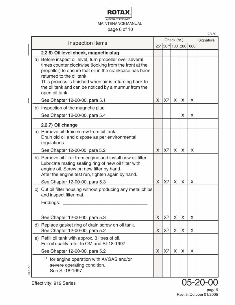
2.2.6) Oil level check, magnetic pluga) Before inspect oil level, turn propeller over several
times counter clockwise (looking from the front at thepropeller) to ensure that oil in the crankcase has beenreturned to the oil tank.This process is finished when air is returning back tothe oil tank and can be noticed by a murmur from theopen oil tank.
See Chapter 12-00-00, para 5.1 X X(1 X X X
b) Inspection of the magnetic plug
See Chapter 12-00-00, para 5.4 X X
2.2.7) Oil changea) Remove oil drain screw from oil tank.
Drain old oil and dispose as per environmentalregulations.
See Chapter 12-00-00, para 5.2 X X(1 X X X
b) Remove oil filter from engine and install new oil filter.Lubricate mating sealing ring of new oil filter withengine oil. Screw on new filter by hand.After the engine test run, tighten again by hand.
See Chapter 12-00-00, para 5.3 X X(1 X X X
c) Cut oil filter housing without producing any metal chipsand inspect filter mat.
Findings: _________________________________
_________________________________________
See Chapter 12-00-00, para 5.3 X X(1 X X X
d) Replace gasket ring of drain screw on oil tank.See Chapter 12-00-00, para 5.2 X X(1 X X X
e) Refill oil tank with approx. 3 litres of oil.For oil quality refer to OM and SI-18-1997
See Chapter 12-00-00, para 5.2 X X(1 X X X(1 for engine operation with AVGAS and/or
severe operating condition.See SI-18-1997.
page 6 of 1007176

MAINTENANCE MANUALAIRCRAFT ENGINES
Effectivity: 912 Series
d036
22
05-20-00page 10
Rev. 3, October 01/2005
Inspection itemsCheck (hr.)
25* 100 200 60050**
Signature
2.2.8) Cleaning of the cooling systema) Flushing of the cooling system.
See Chapter 12-00-00, para 3.3 X X
2.2.9) Check of the air filtera) Inspection of the air filter.
See Chapter 12-00-00, para 2.4 X X X X X
page 7 of 1007176

Effectivity: 912 Series
MAINTENANCE MANUALAIRCRAFT ENGINES
d036
22
05-20-00page 11
Rev. 3, October 01/2005
Inspection itemsCheck (hr.)
25* 100 200 60050**
Signature
2.2.10) Inspection of the carburetor socketsa) Inspect the carburetor sockets for damage and
abnormalities, including obstructions, cracks, wear andcondition.Take note of temperature influence.
See Chapter 13 of Heavy MM, p/n 899 601 X X
2.2.11) Check of the carburetorsa) Verification of the idle speed.
See Chapter 12-00-00, para 4.2 X X X X X
b) Verification of the float chamber venting.Inspect venting lines for condition and damage inclu-ding for condition, secure attachment, clear passagerouting without kinks and restrictions. X X X X X
c) Inspect free movement of the carburetor activation(throttle lever and starting carb).Inspect that the Bowden cable allows the full travelof the throttle lever.
See Chapter 12-00-00, para 4.3 X X X X X
d) Inspect the carburetors:Remove, disassemble, clean, inspect all componentsincluding jetting, leakage test of float needle valve,reassemble and reinstall the carburetors.
See Chapter 13 of Heavy MM, p/n 899 601 X X
e) Inspect carburetor synchronization.Mechanical and pneumatic synchronization.
See Chapter 12-00-00, para 4.1 X X X X X
page 8 of 1007176
MAINTENANCE MANUALAIRCRAFT ENGINES
Effectivity: 912 Series
d036
22
05-20-00page 12
Rev. 3, October 01/2005
Inspection itemsCheck (hr.)
25* 100 200 60050**
Signature
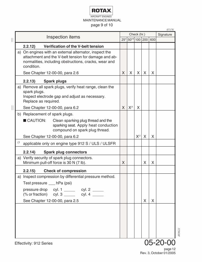
2.2.12) Verification of the V-belt tensiona) On engines with an external alternator, inspect the
attachment and the V-belt tension for damage and ab-normalities, including obstructions, cracks, wear andcondition.
See Chapter 12-00-00, para 2.6 X X X X X
2.2.13) Spark plugsa) Remove all spark plugs, verify heat range, clean the
spark plugs.Inspect electrode gap and adjust as necessary.Replace as required.
See Chapter 12-00-00, para 6.2 X X(1 X
b) Replacement of spark plugs.
■ CAUTION: Clean sparking plug thread and thesparking seat. Apply heat conductioncompound on spark plug thread.
See Chapter 12-00-00, para 6.2 X(1 X X(1 applicable only on engine type 912 S / ULS / ULSFR
2.2.14) Spark plug connectorsa) Verify security of spark plug connectors.
Minimum pull-off force is 30 N (7 lb). X X X
2.2.15) Check of compressiona) Inspect compression by differential pressure method.
Test pressure ___ hPa (psi)
pressure drop cyl. 1 _____ cyl. 2 _____(% or fraction) cyl. 3 _____ cyl. 4 _____
See Chapter 12-00-00, para 2.5 X X
page 9 of 1007176
Effectivity: 912 Series
MAINTENANCE MANUALAIRCRAFT ENGINES
d036
22
05-20-00page 13
Rev. 3, October 01/2005
Inspection itemsCheck (hr.)
25* 100 200 60050**
Signature
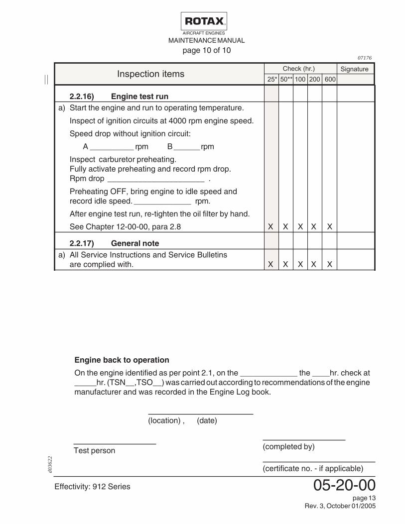
2.2.16) Engine test runa) Start the engine and run to operating temperature.
Inspect of ignition circuits at 4000 rpm engine speed.
Speed drop without ignition circuit:
A __________ rpm B______rpm
Inspect carburetor preheating.Fully activate preheating and record rpm drop.Rpm drop ______________________ .
Preheating OFF, bring engine to idle speed andrecord idle speed. _____________ rpm.
After engine test run, re-tighten the oil filter by hand.
See Chapter 12-00-00, para 2.8 X X X X X
2.2.17) General notea) All Service Instructions and Service Bulletins
are complied with. X X X X X
Engine back to operation
On the engine identified as per point 2.1, on the _____________ the ____hr. check at_____hr. (TSN__,TSO__) was carried out according to recommendations of the enginemanufacturer and was recorded in the Engine Log book.
(location) , (date)
(completed by)
(certificate no. - if applicable)
Test person
page 10 of 1007176

MAINTENANCE MANUALAIRCRAFT ENGINES
Effectivity: 912 Series
d011
99
05-20-00page 14
Rev. 1, Jan. 01/2002
tax-
airc
raft-
engi
nes.
com
www.rota
x-ai
rcra
ft-en
gine
s.co
m
www.rota
x-ai
rcra
ft-en
gine
s.co
m
www.rota
x-ai
rcra
ft-en
gine
s.co
m
www.rota
x-ai
rcra
ft-en
gine
s.co
m
com
www.rota
x-ai
rcra
ft-en
gine
s.co
m
www.rota
x-ai
rcra
ft-en
gine
s.co
m
-eng
ines
.com
www.rota
x-ai
rcra
ft-en
gine
s.co
m
aft-e
ngin
es.c
om
www.rota
x-ai
rcra
ft-en
gine
s.co
m
www.rota
x-ai
rcra
ft-en
gine
s.co
m
Www.ro
tax-
airc
raft-
engi
nes.
com
www.rota
x-ai
rcra
www.rota
x-ai
rcra
ft-en
gine
s.co
m

Effectivity: 912 Series
MAINTENANCE MANUALAIRCRAFT ENGINES
d012
00
05-50-00page 1
Rev. 1, Jan. 01/2002
CHAPTER 05-50
UNSCHEDULED MAINTENANCE CHECKS
1) General noteSpecial checks are required immediacy after occurrence of engine trouble which hasan unfavourable influence on the airworthiness of the engine.
▲ WARNING: In the course of special checks specify if additional checking forcomponents (e.g. hydraulic governor) is applicable.
After each special check/repair work, an engine test run and a leakagecheck must be conducted.
▲ WARNING: Observe without fail all the specified instructions.

MAINTENANCE MANUALAIRCRAFT ENGINES
Effectivity: 912 Series
d036
23
05-50-00page 2
Rev. 3, October 01/2005
2) Special checks
2.1) Checking of propeller gearbox / engine.Engine check after propeller strike resulting in heavy propeller blade damage.
2.1.1) Propeller gearbox with integrated overload clutch- Inspection of engine for damage.
If any damage is detected, inspect, repair or overhaul the engine inaccordance with the ROTAX® instructions for continued airworthi-ness.
- The scope of work depends on the seriousness of the damage.
- Inspect all systems for correct function.
- Inspect additional equipment (external alternator, hydraulic gover-nor, ignition unit, coolant and oil hoses) for damage.
- Observe directives of the aircraft manufacturer.
- Inspect drive of the hydraulic governor (if fitted)
- Remove gearbox and roller bearing of propeller shaft.
The gearbox must be inspected, repaired or overhauled in accord-ance with the ROTAX
® instructions for continued airworthiness.
- Detailed inspection of all gearbox components.
- NDT for cracks on gear cover, propeller shaft and gear set.
- Inspect drive for governor and vacuum pump (if applicable).
- Observe manufacturer instructions for governor.
- Inspect the crankshaft for out-of-roundness. See Chapter 14.4.15 ofHeavy MM, p/n 899 601.
2.1.2) Propeller gearbox without integrated overload clutch- The whole engine must be inspected, repaired or overhauled in
accordance with the ROTAX® instructions for continued airworthi-
ness.
- Detailed inspection of affected engine components.
- NDT for cracks on crankcase, gear cover, flywheel hub, propellershaft and gear set.
- Crankshaft must be overhauled
- Inspect additional equipment (external alternator, hydraulic gover-nor, ignition unit, coolant and oil hoses) for damage.
- Observe directives of the aircraft manufacturer.
Effectivity: 912 Series
MAINTENANCE MANUALAIRCRAFT ENGINES
d036
23
05-50-00page 3
Rev. 3, October 01/2005
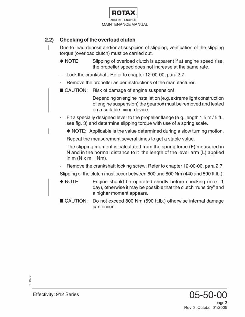
2.2) Checking of the overload clutchDue to lead deposit and/or at suspicion of slipping, verification of the slippingtorque (overload clutch) must be carried out.
◆ NOTE: Slipping of overload clutch is apparent if at engine speed rise,the propeller speed does not increase at the same rate.
- Lock the crankshaft. Refer to chapter 12-00-00, para 2.7.
- Remove the propeller as per instructions of the manufacturer.
■ CAUTION: Risk of damage of engine suspension!
Depending on engine installation (e.g. extreme light constructionof engine suspension) the gearbox must be removed and testedon a suitable fixing device.
- Fit a specially designed lever to the propeller flange (e.g. length 1,5 m / 5 ft.,see fig. 3) and determine slipping torque with use of a spring scale.
◆ NOTE: Applicable is the value determined during a slow turning motion.
Repeat the measurement several times to get a stable value.
The slipping moment is calculated from the spring force (F) measured inN and in the normal distance to it the length of the lever arm (L) appliedin m (N x m = Nm).
- Remove the crankshaft locking screw. Refer to chapter 12-00-00, para 2.7.
Slipping of the clutch must occur between 600 and 800 Nm (440 and 590 ft.lb.).
◆ NOTE: Engine should be operated shortly before checking (max. 1day), otherwise it may be possible that the clutch “runs dry” anda higher moment appears.
■ CAUTION: Do not exceed 800 Nm (590 ft.lb.) otherwise internal damagecan occur.

MAINTENANCE MANUALAIRCRAFT ENGINES
Effectivity: 912 Series
d036
23
05-50-00page 4
Rev. 3, October 01/2005
If the torque is below or above this value, inspect, repair or overhaul the propellergearbox in accordance with the ROTAX® instructions for continued airworthi-ness.
- Detailed inspection of all gearbox components.
Fig.308545
Kraft F in N/force F in N
Länge L (m)/length L in m
Effectivity: 912 Series
MAINTENANCE MANUALAIRCRAFT ENGINES
d036
23
05-50-00page 5
Rev. 3, October 01/2005
2.3) Examination after engine failureAfter an engine failure find the cause of the failure by troubleshooting, using thefollowing indicators. Also, observations on the aircraft and the engine mount canbe of help.
Engine runs erratic and misfires
May be caused by a failure of the fuel system (fuel supply, vapour locks,contamination, float chamber venting, false air intake due to defective carburetorflange, carburetor icing), or of the ignition system (shorting cable, electronicmodule, spark plugs, wrong spark plug connection, grounding defect, chargingcoil etc.). See details regarding fuel- and ignition system.
Engine running rough
May be caused by a failure of the ignition system or a fault in the carburetor maybe the reason (fuel supply, contamination in float chamber or float needle valve,float chamber venting, false air intake due to defective carburetor flange, enginetemperature too low, too lean carburetor jetting due to conditions prevailing inintake silencer).
Cylinder head temperature
May be caused by a rise in cylinder head temperature above normal operatinglimits (see Operator’s Manual) is a clear signal for a failure in the cooling system:
- insufficient coolant, badly vented system, return valve in cap does not work
- radiator contaminated, radiator cap leaking, pressure relief valve in capdoes not work,
- malfunction of water pump.
Unintended engine stoppage by seizing
May be caused by a failure in the lubricating system. Oil pressure too low or nooil pressure due to oil shortage, contamination or bad venting of the oil system,defective oil pump. As a consequent damage, often the camshaft and/or theconrod bearings maybe seized.
- The whole engine must be inspected, repaired or overhauled in accordancewith the ROTAX
® instructions for continued airworthiness.
- Inspect all systems for correct function.
- Detailed inspection of affected engine components.
▲ WARNING: If one of the above failures should arise even only for a short time,a detailed inspect is necessary. Localize trouble and rectify.

MAINTENANCE MANUALAIRCRAFT ENGINES
Effectivity: 912 Series
d012
00
05-50-00page 6
Rev. 1, Jan. 01/2002
2.4) Engine back to operation after submerging in waterAn engine having been submerged in water must be inspected, repaired oroverhauled in accordance with the ROTAX® instructions for continued airworthi-ness.
- Inspect all systems for correct function.
- Detailed inspection of affected engine components.
■ CAUTION: The engine must be marked clearly with the note „Enginesubmerged in water“.
2.5) Checks in extreme climatic conditionsFlying in deserts or areas with heavily contaminated or dusty air causesincreased wear on all components. Therefore shorter maintenance intervals arerecommended.
▲ WARNING: Every 25 h checks of air filter, coolant radiator and oil cooler arenecessary.
Flying in areas of extreme climatic conditions or in extreme altitudes requirescorrection of carburetor jetting and of the cooling system. This requires consul-tation with the A/C manufacturer and authorized ROTAX
® Distributor.

Effectivity: 912 Series
MAINTENANCE MANUALAIRCRAFT ENGINES
d012
00
05-50-00page 7
Rev. 1, Jan. 01/2002
2.6) Exceeding of max. admissible engine RPM◆ NOTE: Any exceeding of the max. admissible engine RPM must be
entered by the pilot into the Engine Log book stating durationextent of overspeeding and pertinent detail.
- Exceeding for max. 1 minute up to 6200 rpm:- Inspect push rods for straightness.
- Exceeding for more than 1 minute:
The whole engine must be inspected, repaired or overhauled in accordancewith the ROTAX
® instructions for continued airworthiness.
- Inspect push rods for straightness.
- Inspect all systems for correct function.
- Detailed inspection of affected engine components.
- Exceeding 6200 rpm:
The whole engine must be inspected, repaired or overhauled in accordancewith the ROTAX® instructions for continued airworthiness.
- Inspect push rods for straightness.
- Inspect all systems for correct function.
- Detailed inspection of affected engine components.

MAINTENANCE MANUALAIRCRAFT ENGINES
Effectivity: 912 Series
d036
23
05-50-00page 8
Rev. 3, October 01/2005
2.7) Exceeding of cylinder head temperature◆ NOTE: Any exceeding of the max. admissible cylinder head tempera-
ture must be entered by the pilot into the Engine Log book,stating duration extent of excess temperature and pertinentdetail.
■ CAUTION: On exceedance of cylinder head temperature often anexceedance of other limits, e.g. of oil temperature, occurs too.Follow the relevant instructions.
2.7.1) Exceedance up to 180 °C (360 °F) - for a short timeAt short term exceeding of the cylinder head temperature of up to 180°C(360°F):- The whole cooling system must be inspected, repaired or overhauled
in accordance with the ROTAX® instructions for continued
airworthiness.- Inspect all further systems for correct function.
Detailed inspection of affected engine components as- Leakage check of cooling system.- Check cylinder head fixation for tight fit. At loose cylinder head nut
follow the procedure according para 2.7.2.- Check all coolant fittings (inlet/outlet) for tight fit.
2.7.2) Exceedance over 180 °C (360 °F) and/or longer than 30 min.If a cylinder head temperature above 180°C (360°F) is noticed and/orlonger than 30 minutes:
Procedureacc. para 2.7.1
Procedure acc. para 2.7.2
30 min.
operating limit
time07140
150 °C(300 °F)
180 °C(360 °F)
0
temperature
- The whole cooling system must beinspected, repaired or overhauled in ac-cordance with the ROTAX® instructionsfor continued airworthiness.
- Inspect all further systems for correctfunction.
- Detailed inspection of affected enginecomponents.
- Inspect compression by the differentialpressure method.
- Dismantle all cylinder heads andcylinders and perform a detailedinspection including hardness test.See para 14.5.7 of Maintenance ManualII (HeavyMaintenance).

Effectivity: 912 Series
MAINTENANCE MANUALAIRCRAFT ENGINES
d036
23
05-50-00page 9
Rev. 3, October 01/2005
2.8) Exceeding of the oil temperature◆ NOTE: Any exceeding of the max. admissible oil temperature must be
entered by the pilot into the Engine Log book, stating durationextent of excessive temperature and pertinent details.
■ CAUTION: On exceedance of oil temperature often an exceedance of otherlimits, e.g. of cylinder head temperature, occurs too. Follow therelevant instructions.
2.8.1) Exceedance over 140 °C (280 °F) for max. 15 min.On exceedance over 140°C (280°F) for max. 15 min. localise the cause.
- The whole oil system must be inspected, repaired or overhauled inaccordance with the ROTAX
® instructions for continued
airworthiness.
- Inspect all further system for correct function.
- Inspect oil level in the oil tank.
- Inspect oil cooler for contamination and check oil circuit for operation.
- Inspect oil lines for correct laying and damage.
- Cut oil filter housing and inspect filter mat for foreign matter.
- Carry out oil change.
2.8.2) Exceedance over 160 °C (320 °F)With oil temperature in excess of 160°C (320°F) consequential damageis likely.
Procedureacc. para 2.8.1
Procedure acc. para 2.8.2
30 min.
operating limit
time07140
140 °C(280 °F)
160 °C(320 °F)
0
temperature
- The whole engine must be inspected,repaired or overhauled in accordancewith the ROTAX® instructions for con-tinued airworthiness.
- Inspect all further systems for correctfunction.
- Detailed inspection of affected enginecomponents.
- Cut oil filter housing and inspect filtermat for foreign matter.
MAINTENANCE MANUALAIRCRAFT ENGINES
Effectivity: 912 Series
d012
00
05-50-00page 10
Rev. 1, Jan. 01/2002
2.9) Oil pressure below minimum valueIf noticed on ground, immediately stop the engine and determine the cause.
- Inspect the complete lubrication system, trace cause and rectify.See SI-912-005.
Oil pressure below 0,5 bar (7 psi.) at flight
◆ NOTE: Any oil pressure below 0,5 bar (7 psi) must be entered by the pilotin the Engine Log book stating duration extent of oil pressurebelow minimum and pertinent detail.
- Inspect all oil lines for restrictions and clear passage.
- Verify oil quantity.
- Inspect pressure sensor.
- Inspect indicating instrument to specifications of the manufacturer, replaceas required.
- Verify function of the pressure relief valve.
- If no cause for the low oil pressure is found after the above checks, carry outan oil change.
- If after the previous checks and oil change the oil pressure is still too low,repair or overhaul the engine in accordance with the ROTAX
® instructions for
continued airworthiness.
- Inspect all systems for correct function.
- Detailed inspection of affected engine components.
■ CAUTION: Replaced the oil cooler inclusive oil lines and before the re-installation of the engine the complete lubrication system (inclu-sive oil tank) must be flushed.

Effectivity: 912 Series
MAINTENANCE MANUALAIRCRAFT ENGINES
d036
24
12-00-00page 5
Rev. 3, October 01/2005
2.2) Leakage checkVisual inspection of the whole engine for leaks.
◆ NOTE: If a leak is suspected following check is possible:
Operate the engine until the temperatures have stabilised for a period of 5 min.Switch off ignition and secure engine against unintentional operation. Secureaircraft against unauthorized operation. After shut down of engine no liquid mustdrip down within 1 min.
If the leakage bore, located at the base of the ignition housing, is dripping oil, theoil seal on the water pump shaft may be defective and must be replaced. In thecase of coolant drips at the leakage bore, the coolant mechanical seal must bereplaced.
Inspect fuel lines, their connections andscrew fasteners. Look for scuffing marks.Inspect isolating flange of fuel pump forleaks.
Detailed visual inspection specially onsteel fuel lines (1) in the area ofconnections (fittings) (2) for leaks andcracks is necessary. See fig. 1/1.
1
2
1
2
2
09034
Fig. 1/1
Inspect all engine oil lines for damage, security and restrictions.
Inspect fuel, water lines, their connections and screw plugs for tightness. Checksurrounding area for leaks.
At signs of operating media leaks find the reason and repair as required.
Inspect all hoses, especially in the area of hose clamps and hose connectionsfor porosity, damages or kinks. If damage is noticed, replace hose immediately.
■ CAUTION: Avoid overstressing of fastening elements and secure till handtight.

MAINTENANCE MANUALAIRCRAFT ENGINES
Effectivity: 912 Series
d013
76
12-00-00page 6
Rev. 1, Jan. 01/2002
2.3) Check of the engine suspensionVerify the engine mount points on the crankcase for tight fit and damageincluding cracks.
Inspect the surroundings of engine attachment on crankcase and gearbox. Atdiscoloration of the crankcase around the fixation points (black ring), suspectloose fasteners.
Inspect engine isolating mounts including for heat damage, wear and cracks.
▲ WARNING: Adhere to specified tightening torques of screws and nuts with-out fail. Overtightening or too loose connection could causeserious engine damage.

Effectivity: 912 Series
MAINTENANCE MANUALAIRCRAFT ENGINES
d036
24
12-00-00page 9
Rev. 3, October 01/2005
2
6 b
ar /
87 p
sibar
05
67
431
2
bar
0
5
6
432
1 7
Ø 1mm (0,039 in.)L = 3 mm (0,12 in.)
45
21 3
Zyl. Kopf /cyl. head
fig. 300156
2.5) Check of compressionSee fig. 3.
▲ WARNING: Ignition switch for both ignition circuit in „OFF“ position.
Check has to be done with suitable cylinder differential test equipment.
■ CAUTION: Following equipment is necessary:Compressed air supply of approx. 6 bar (87 psi), two pressuregauges, an orifice (2) of 1 mm (.04 in) dia. and 3 mm (.12 in) lengthand an adaptor (1) to connect line to tapped spark plug hole.
PROCEDURE:Bring engine to operating temperature.Bring crankshaft into ignition-OT-position.Remove only respective bottom spark plugto ensure that possible dirt does not comeinto the engine. Install adaptor (1) in sparkplug hole and connect line with the twopressure gauges and intermediate orifice(2). Hold piston on TDC with propeller.Now put constant pressure of approx. 6 bar(approx. 87 psi) on the line (3) and takereadings on pressure gauges (4) and (5).The maximum allowable pressure drop is25 %, e.g. from 6 to 4,5 bar (87 psi to 65 psi).
If compression is below the limit 4,5 bar (65 psi) the whole engine must beinspected, repaired or overhauled in accordance with the ROTAX
® instructions
for continued airworthiness.- Detailed inspection of affected engine components.◆ NOTE: In the course of fault-tracing a direct compression check may
be performed too:A compression tester is required to check compression. The compressionshould be between 9 and 12 bar (130 and 174 psi).
PROCEDURE:Bring engine to operation temperature (engine oil temperature between 30 to70°C (90 - 160°F)). Remove top spark plug and press compression tester againstplug tap hole and set engine with open throttle into rotation by activating starteruntil maximum pressure is reached.Successively take readings on all four cylinders and compare results. Individualreadings of the cylinders must not differ by more than 2 bar (29 psi).If readings are below 6 bar (87 psi), the whole engine must be inspected,repaired or overhauled in accordance with the ROTAX® instructions for contin-ued airworthiness.
- Detailed inspection of affected engine components.

MAINTENANCE MANUALAIRCRAFT ENGINES
Effectivity: 912 Series
d013
76
12-00-00page 10
Rev. 1, Jan. 01/2002
2
1
3
00353
fig. 4
F = 50 N
6 m
m
00354
fig. 5
2.6) Check of V-belt tensionSee fig. 4 and 5.
At configuration with additional external alternator, inspect attachment and V-belt tension.
For adjustment of the V-belt tension, loosen the hex. screw M10 (1) and the twoAllen screws M8 (2) and (3). Push alternator upward and tighten Allen screw (3).Then tighten the screws (1) and (2).
Torque screws M8 to 22 Nm (195 in.lb) and
screw M10 to 35 Nm (310 in.lb).
Inspect V-belt tension as per drawing below.
(422 in.lb)
(0.2
4 in
)

Effectivity: 912 Series
MAINTENANCE MANUALAIRCRAFT ENGINES
d013
76
12-00-00page 15
Rev. 1, Jan. 01/2002
00155 fig. 6
1
3.2) Renewal of the coolantSee fig. 6.
Open the radiator cap, remove the bottom attachment screw (1) (with sealingring) of water pump and drain the coolant.
◆ NOTE: If the radiator is located below the engine, detach also the lowestpositioned coolant hose.
Install attachment screw (stainless steel) along with a new sealing ring. Tightento 10 Nm (90 in.lb).
Refill newly mixed coolant into expansion tank (highest point of the coolingsystem). Install radiator cap.
◆ NOTE: Run the engine for a minute and replenish with clean coolant asrequired. Ensure that all air is purged from system.
▲ WARNING: Never open radiator cap when the cooling system is hot. Forsafety’s sake, cover cap with a cloth and open slowly. Suddenopening of the cap would provoke exit of boiling coolant andresult in severe scalds.
3.3) Flushing of the cooling systemThis can be done with a water hose at a max. pressure of 2 bar (30 p.s.i.).
◆ NOTE: For the flushing, open the lowest located coolant hose (either atwater pump or radiator).
Refill newly mixed coolant into the expansion tank (highest point of the coolingsystem).
◆ NOTE: Run the engine for a minute and replenish coolant as required.
▲ WARNING: Never open radiator cap when the cooling system is hot. Forsafety’s sake, cover cap with a cloth and open slowly. Suddenopening of the cap would provoke exit of boiling coolant andresult in severe scalds.

MAINTENANCE MANUALAIRCRAFT ENGINES
Effectivity: 912 Series
d036
24
12-00-00page 16
Rev. 3, October 01/2005
00394
00393
7
8
00395
fig. 6/1
fig. 6/2
fig. 6/3
3.4) Expansion tank, radiator capsee fig. 6/1 to 6/3
Inspect the rubber seal (3) including for cracks, leaks. The pressure spring (4)and the two valves incorporated in the radiator cap. If required replace by a neworiginal radiatorcap (6) with 1,2 bar (17 psi) opening pressure.
Inspect sealing face (7) and tube connection (8) of the expansion tank. Inspecttank for damage and scuffing marks.
Legend:
1 pressure release valve2 return valve3 rubber seal4 pressure spring5 connection to overflow bottle6 opening pressure of the radiator cap7 sealing face8 tube connections
��� ���
6
Effectivity: 912 Series
MAINTENANCE MANUALAIRCRAFT ENGINES
d036
24
12-00-00page 27
Rev. 3, October 01/2005
7
3
05556
fig. 16
4
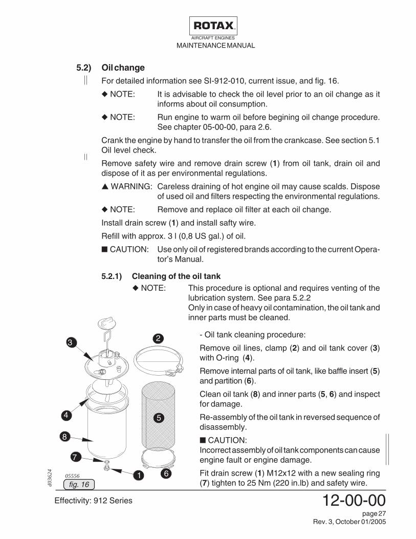
5.2) Oil changeFor detailed information see SI-912-010, current issue, and fig. 16.
◆ NOTE: It is advisable to check the oil level prior to an oil change as itinforms about oil consumption.
◆ NOTE: Run engine to warm oil before begining oil change procedure.See chapter 05-00-00, para 2.6.
Crank the engine by hand to transfer the oil from the crankcase. See section 5.1Oil level check.
Remove safety wire and remove drain screw (1) from oil tank, drain oil anddispose of it as per environmental regulations.
▲ WARNING: Careless draining of hot engine oil may cause scalds. Disposeof used oil and filters respecting the environmental regulations.
◆ NOTE: Remove and replace oil filter at each oil change.
Install drain screw (1) and install safty wire.
Refill with approx. 3 l (0,8 US gal.) of oil.
■ CAUTION: Use only oil of registered brands according to the current Opera-tor’s Manual.
5.2.1) Cleaning of the oil tank◆ NOTE: This procedure is optional and requires venting of the
lubrication system. See para 5.2.2Only in case of heavy oil contamination, the oil tank andinner parts must be cleaned.
4
- Oil tank cleaning procedure:
Remove oil lines, clamp (2) and oil tank cover (3)with O-ring (4).
Remove internal parts of oil tank, like baffle insert (5)and partition (6).
Clean oil tank (8) and inner parts (5, 6) and inspectfor damage.
Re-assembly of the oil tank in reversed sequence ofdisassembly.
■ CAUTION:Incorrect assembly of oil tank components can causeengine fault or engine damage.
Fit drain screw (1) M12x12 with a new sealing ring(7) tighten to 25 Nm (220 in.lb) and safety wire.
4
3
1 6
5
2
8

MAINTENANCE MANUALAIRCRAFT ENGINES
Effectivity: 912 Series
d036
24
12-00-00page 28
Rev. 3, October 01/2005
5.2.2) Venting of the lubrication systemSee fig. 16/1.
■ CAUTION: Purging of the lubrication system is extremely impor-tant for operation and life of the engine and therefore ithas to be followed meticulously. See therefore alsoSI-04-1997, latest edition.
Fill oil tank with motor oil.
▲ WARNING: Ignition „OFF“ and system grounded. Disconnect nega-tive terminal of aircraft battery.
Disconnect suction hose (1) from oil tank and fill the oil hose with oilutilizing a suitable funnel. By cranking the engine with a few turns of thepropeller oil will be sucked in by the oil pump.
◆ NOTE: As in the suction line of the oil pump an oil cooler isinstalled, this procedure will take a bit longer as thecooler has to be filled with oil first.
Reconnect oil suction line on tank and crank engine with starter but withignition ‘OFF’ until steady min. oil pressure is indicated on oil pressuregauge.
Switch on ignition and start engine and observe oil pressure.
■ CAUTION: The oil pressure must rise within 10 seconds to at least2 bar (30 psi). If not stop the engine instantly and purgethe suction line between the oil tank and oil pump againas stated above.
After short idling, stop engine and replenish oil to max. mark on dip stick.Never overfill, otherwise oil would escape through the vent tube duringoperation. At oil level inspect, do not exceed the max. mark.

Effectivity: 912 Series
MAINTENANCE MANUALAIRCRAFT ENGINES
d036
24
12-00-00page 29
Rev. 3, October 01/2005
IN
OUT
05448
backfrom engine
to oil pump
1
1
6
83
2
4
5
7
1
fig. 16/1
05493
■ CAUTION: For further helpful information refer to SI-04-1997,Venting of the lubrication system, current issue.
MAINTENANCE MANUALAIRCRAFT ENGINES
Effectivity: 912 Series
d030
12
12-00-00page 30
Rev. 2, March. 01/2003
Filt
erto
pffil
ter
hous
ing
Pap
iere
insa
tz /
filte
r m
atF
ilter
elem
ent /
filte
r el
emen
t
Dic
htrin
g /
gask
et r
ing
von der Ölpumpe /from oil pump
zur Lagerstelle /to bearings
Filt
erde
ckel
/fil
ter
cove
r
02734
fig. 16
877
620
877
670
00349
fig. 16/1
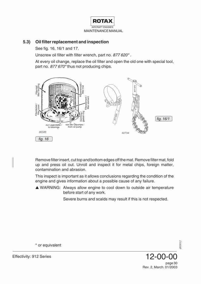
5.3) Oil filter replacement and inspectionSee fig. 16, 16/1 and 17.
Unscrew oil filter with filter wrench, part no. 877 620* .
At every oil change, replace the oil filter and open the old one with special tool,part no. 877 670* thus not producing chips.
Remove filter insert, cut top and bottom edges off the mat. Remove filter mat, foldup and press oil out. Unroll and inspect it for metal chips, foreign matter,contamination and abrasion.
This inspect is important as it allows conclusions regarding the condition of theengine and gives information about a possible cause of any failure.
▲ WARNING: Always allow engine to cool down to outside air temperaturebefore start of any work.
Severe burns and scalds may result if this is not respected.
* or equivalent

Effectivity: 912 Series
MAINTENANCE MANUALAIRCRAFT ENGINES
d013
76
12-00-00page 37
Rev. 1, Jan. 01/2002
tax-
airc
raft-
engi
nes.
com
www.rota
x-ai
rcra
ft-en
gine
s.co
m
www.rota
x-ai
rcra
ft-en
gine
s.co
m
www.rota
x-ai
rcra
ft-en
gine
s.co
m
www.rota
x-ai
rcra
ft-en
gine
s.co
m
com
www.rota
x-ai
rcra
ft-en
gine
s.co
m
www.rota
x-ai
rcra
ft-en
gine
s.co
m
-eng
ines
.com
www.rota
x-ai
rcra
ft-en
gine
s.co
m
aft-e
ngin
es.c
om
www.rota
x-ai
rcra
ft-en
gine
s.co
m
www.rota
x-ai
rcra
ft-en
gine
s.co
m
Www.ro
tax-
airc
raft-
engi
nes.
com
www.rota
x-ai
rcra
www.rota
x-ai
rcra
ft-en
gine
s.co
m

MAINTENANCE MANUALAIRCRAFT ENGINES
Effectivity: 912 Series
d036
24
12-00-00page 38
Rev. 3, October 01/2005
00086
6.2) Verification or replacement of spark plugs■ CAUTION: Observe the different maintenance intervals corresponding to
engine type.
Because of the differing thermal load, particular spark plugs have been specifiedfor each engine type.
In numerous tests the best possible heat range has been determined to makesure that the spark plug will burn off deposits but will not overheat.
▲ WARNING: Use of incorrect spark plugs can result in ignition problems, pre-ignition and consequent engine damage.
Refer to Chapter 05-50-00, para 2.11.
Ensure that the following spark plugs corresponding to engine type are em-ployed and the correct spark plug socket is used.
Engine type designation size of socket
912 UL/A/F DCPR 7E 16 mm
912 ULS/S DCPR 8E 16 mm
Electrode gap: 0,7 - 0,8 mm (0,0276 - 0,0315 inch)
◆ NOTE: If cold start problems are encountered, the electrode gap may bereduced to 0,5 mm (0,0197 inch)
- inspect all spark plugs for physical damage.
- verify the heat range and the electrode gap of the spark plugs.
1
2■ CAUTION: Heat conduction paste at the ground electrode (1) or the head
area (2) can lead to ignition fault. Apply heat conduction pastesparingly and do not apply to the first 3 thread turns.
Before every installation the spark plug thread and the spark plug seat at thecylinder head should be cleaned. Apply small amount of heat conduction pasteon spark plug thread and tighten spark plug to 20 Nm (177 in.lb) on the coldengine. Heat conduction paste, see Chapter 05-00-00, para 2.5.
▲ WARNING: Flush with water in case of contact with eyes or skin. May beharmful if swallowed.
Always replace both spark plugs of a cylinder and do not interchange sparkplugs between cylinders.

Effectivity: 912 Series
MAINTENANCE MANUALAIRCRAFT ENGINES
d036
24
12-00-00page 41
Rev. 3, October 01/2005
Kraft F in N /force F in N
Länge L (m) /length L in m
fig. 1805694
7.1) Checking of the friction torqueSee fig. 18.
- Fit the crankshaft locking pin. See Chapter 12-00-00, para 2.7.
- With the crankshaft locked, the propeller can be turned by hand 15 or 30degrees depending on the profile of the dog gears installed.
This is the amount of movement allowed by the dog gears in the torsion loadabsorption unit.
▲ WARNING: Ignition “OFF” and system grounded. Disconnect negative ter-minal of aircraft battery.
- Turn the propeller by hand back and forth between ramps, taking intoconsideration the friction torque. No odd noises or irregular resistance mustbe noticeable during this moment.
- Attach a calibrated spring scale to the propeller in distance (L) from thecenter of the propeller. Measure the force required to pull the propellerthrough the 15 or 30 degree range of rotation. (See Fig. 3)
- Calculate friction torque (Nm) by multiplying the force (N) obtained on thespring scale by the distance the scale is attached from the center of thepropeller (L).
The friction torque must be min. 25 Nm to max. 60 Nm (220 to 530 in. lb). Seecalculation example.
- Remove crankshaft locking pin. See Chapter 12-00-00, para 2.7.
- Install plug screw M8x20 allong with the new gasket ring.See Chapter 12-00-00, para 2.7.
- Reconnect negative terminal of aircraft battery.
▲ WARNING: If the above mentioned friction torque is not achieved, inspect,repair or overhaul the gearbox in accordance with the ROTAX
®
instructions for continued airworthiness.
- Detailed inspection of all gearbox components.
For example minimum torque:F x L = 33 N x 0,76 m = 25 Nm
For example maximum torque:F x L = 79 N x 0,76 m = 60 Nm

MAINTENANCE MANUALAIRCRAFT ENGINES
Effectivity: 912 Series
d036
24
12-00-00page 42
Rev. 3, October 01/2005
7.2) Inspection of propeller gearboxThe whole gearbox must be inspected, repaired or overhauled in accordancewith the ROTAX® instructions for continued airworthiness.
Detailed inspection of affected gearbox components acc. para 14.4.12 ofMaintenance Manual II (Heavy Maintenance).
An inspection for cracks of propeller shaft is usually not foreseen, but can bedone at unclarity or suspicion.


![[XLS] Web view1 99 2 99 3 99 4 99 5 99 6 98 7 98 8 98 9 98 10 98 11 98 12 98 13 98 14 98 15 98 16 98 17 98 18 98 19 98 20 98 21 98 22 98 23 97 24 97 25 97 26 97 27 97 28 97 29 97 30](https://img.pdfslide.us/doc/110x75/5b1e84727f8b9a116d8ba522/xls-web-view1-99-2-99-3-99-4-99-5-99-6-98-7-98-8-98-9-98-10-98-11-98-12-98-13.jpg)