Embed Size (px)
Citation preview
369www.TPCpage.com
www.TPCpneumatics.com
AQADQ
ACP
APM
AS
AX
AM2
AM
ALALX
AQ2ADQ2
AJAJM
ABK
ACK1
NSK
AG
NGQ
AGXGX
NP
ADR
AMR
NDM
ARD
NST
AST
ASTH
NLCD
NLCS
SeriesAGCompact Guide Cylinder
Bore size(mm) : Ø12(1/2 Nom), Ø16(5/8 Nom), Ø20(3/4 Nom), Ø25(1 Nom), Ø32(11/4 Nom), Ø40(11/2 Nom), Ø50(2 Nom), Ø63(21/2 Nom), Ø80(31/4 Nom), Ø100(4 Nom)
●COMPACT SLIM BODY GUIDE CYLINDER
●10 BORE SIZES
●MULTIPLE MOUNTING OPTIONS
●FLUSH MOUNTING-AUTO SWITCH
●AVAILABLE WITH BALL BEARING BUSHINGS
●LOW BREAKAWAY
●DESIGNED FOR NON-LUBE APPLICATIONS
●HIGH LOAD BEARING CHARACTERISTICS
Symbol
How to Order
AG3 4 6 752
Ø12, Ø16
Ø20, Ø25
Ø32, Ø40, Ø50,
Ø63, Ø80, Ø100
10, 20, 30, 40, 50, 75, 100
20, 30, 40, 50, 75, 100
25, 50, 75, 100, 125, 150
Bore Size(mm) Standard Stroke(mm)
Model/Standard Stroke Table
75 W4M
1
U 20
1⃞PortBlank : Rc(PT)
U : NPT
2⃞Type of BearingM : Slide bearing(Suitable
for Stopper)
L : Ball bush bearing
(Suitable for Lifting/
Pushing)
3⃞Bore Size 12 : Ø12mm(1/2 Nom.)
16 : Ø16mm(5/8 Nom.)
20 : Ø20mm(3/4 Nom.)
25 : Ø25mm(1 Nom.)
32 : Ø32mm(11/4 Nom.)
40 : Ø40mm(11/2 Nom.)
50 : Ø50mm(2 Nom.)
63 : Ø63mm(21/2 Nom.)
80 : Ø80mm(31/4 Nom.)
100 : Ø100mm(4 Nom.)
4⃞Cylinder Stroke(mm)Refer to Model/Standard Stroke
Table.
5⃞OptionBlank : Standard
XC16 : Copper-Free
6⃞Auto SwitchBlank : None
Reed switch
W4 : W4(2 wire DC24V,
AC100V)
(Ø32 ~ Ø100)
W13 : W13(z wire, DC24V,
AC110V)
(Ø12 ~ Ø25)
Solid State Switch
W1H : W1H(3 wire system,
DC24V)
(Ø12 ~ Ø25)
※ The standard, lead wire
length is 0.5m “L”is added
for 3m long lead wire
(applicable to all models)
(Example) W4L
W2 : (Ø32 ~ Ø63)
7⃞Number of Auto Switches Blank : 2 pcs
S : 1 pc
N : N pcs
•Intermediate strokeAs to Intermediate stroke(5, 10, 15, 20, 30, 35...), Spacer of
5, 10, 15, 20mm width will be used.
(Example)AGM50-10 is Produced by installing 15mm spacer in
AGM 50-25.
Consult factory when the desired stroke is greater then the
standard stroke.
(Copper-free type is basic for L type of Ø12~Ø40)
(Only L type can be in copper-free type)
369-381-AG 2012.9.7 2:59 PM 페이지369 한국원색인쇄사
Series AG
370
Operation Double Acting
Fluid Air
Proof pressure 1.5MPa(217psi)
Max. operating pressure 1.0MPa(140psi)
Min. operating pressureØ12, 16 : 0.12MPa{1.2kgf/cm2}
Ø25~100 : 0.1MPa{1.0kgf/cm2}
Ambient and fluid temperature -10~+60℃(14。F~140。F)
Piston speed 50~500mm/s
Cushion Rubber Cushion at Both Sides
Lubrication Non-Lubrication
Stroke tolerance mm
Type
W4
W2P
Mounting Parts
BQ-4
BQ-4
BQ-2
TGQ-32
Bore Size
32, 40
50, 63
80, 100
32~63
SpecificationsPart No. of Auto Switch
Material
NBR
NBR
NBR
NBR
Part Name
Piston Packing
Rod Packing
Gasket
Head Cover Gasket
Ø12
TPSA-12
DRY-6
C-10
-
Ø16
TPSA-16
DRY-8
C-14
-
Ø20
TPSA-20
DRY-10SK-K
C-18
-
Ø25
TPSA-25
DRT-12
C-23
-
Ø32
TPSA-32
DRY-16
C-29
TMGQM032-18-1586
Ø40
TPSA-40
PDU-16Z
C-36
TMGQM040-18-1587
Ø50
TPSA-50
PDU-20Z
C-46
TMGQM050-18-1588
Ø63
TPSA-63
PDU-20Z
C-60
TMGQM063-18-1589
Ø80
TPSA-80
PDU-25Z
C-75
TMGQM080-18-1794
Ø100
TPSA-100
PDU-30Z
C-95
TMGQM100-18-1796
Part Number
Packing List / Exchangeing Parts
+1.50
Space saving cylinder.
Provides Non-Rotating support for
side loads. Suitable for conveyor lines
where stopping
and lifting are required.
2 kinds of bearing
Slide Bearing -
Strength against side load
is more than 2 times that
of conventional stopper
cylinders.
Ball Bushing Bearing -
Smooth operation suitable
for pushing, lifting and
applications where high
precision is required.
High Non-Rotating
Load Capability
Bore Non-Rotating AccuracyΘ
size AGM AGL
ф12
ф16
ф20
ф25
ф32
ф40
ф50
ф63
ф80
ф100
±0.07° ±0.10°
±0.06° ±0.09°
±0.06° ±0.08°
±0.05° ±0.06°
±0.04° ±0.05°
+θ
- θ
369-381-AG 2012.9.7 2:59 PM 페이지370 한국원색인쇄사
Series AG
371www.TPCpage.com
www.TPCpneumatics.com
AQADQ
ACP
APM
AS
AX
AM2
AM
ALALX
AQ2ADQ2
AJAJM
ABK
ACK1
NSK
AG
NGQ
AGXGX
NP
ADR
AMR
NDM
ARD
NST
AST
ASTH
NLCD
NLCS
Ø12~Ø25 / AGM·AGL
Grooves(Ø12, Ø16, Ø20, Ø25)
A B C CA CB D DB E EA
Ø12 26 60 13 12.5 13 6 8 6 46 8 5
Ø16 30 67 15 14.5 15 8 10 8 50 8 5
Ø20 36 85 18 17.5 18 10 12 10 58 10 6
Ø25 42 95 21 20.5 21 12 16 13 68 10 6
0 5 34 3 13 13 23 28 7 20 40 25 4.3 8 13.5 18 M5×0.8
0 5 34 5 20 20 30 35 7 24 44 27 4.3 8 12.5 22 M5×0.8
3 5 47 - 12 25 35 42 18 24 44 31 5.5 9.5 13.5 24 M5×0.8
3 5 47 - 18 18 37 48 18 24 44 35 5.5 9.5 14.5 30 M6×1.0
DA
AGM AGL 30stless
30~50stBetween
50stAbove 10st 20st 30st
40·50st
50stAbove
AGM·AGL Common Dimensions
These grooves(W) can be used to firmly
fix the terminal boards.,etc to the main
body of the cylinder.
Model A B C D E F Applicable Bolt
AG□12 3.5 6 2 4.3 1.5 23 M3
AG□16 3.7 6.2 2 4.6 1.5 24 M3
AG□20 5.5 8.5 3.5 7.8 3 28 M5
AG□25 5.5 8.5 3.5 8 3 34 M5
(Unit : mm)
4-TM, Depth TL
FA
4-QM, Thru
4-FM, Depth FLL
(Option)
“U”
C’Bore ØFD,Depth FL
4-ØFC, Thru
UC
QA
S
FAF
EAE
PA PB
EB
GA
CA CB
C
A
UD
UU
QB R
FB
ØUB
ØUAH7
DETAIL “U”
DB
FB
фD
фDA
B
GD
GB
GC
LA+Stroke
LB+Standard Stroke
LL+Standard Stroke
4-GM,Depth GL
F
W W
AG 12AG 16AG 20AG 25B
F
A
E
D C
DETAIL“W”
AG 12~25
BoreSize(mm)
EB
AGLAGMFA
30STAbove
30STLess
F FB FC FD FL FH FM FLL GAGB GCGD GM GL LA LB
12 18 50 23 M3 M4×0.7 10 29 42
12 22 56 24 M3 M5×0.8 12 33 46
13 24 72 28 M5 M5×0.8 13 37 53
15 30 82 34 M5 M6×1.0 15 37.5 53.5
2-P
F FA
※ As to intermediate stroke, spacer will be used.
C’BORE ØTD Depth TLL
Ø12 42 47 76 45 55 55 65 70 M5×0.8 11 8.5 14 48
Ø16 46 51 80 51 66 66 76 81 M5×0.8 11 8 16 54
Ø20 56 58 100 - 65 78 88 95 Rc1/8 10.5 9 18 70
Ø25 56.5 58.5 100.5 - 71.5 71.5 90.5 101.5 Rc1/8 11.5 9.5 26 78
M4×0.7 58 22 M5×0.8 Thru 6 4.3 23 3 3.5 3 6
M5×0.8 65 25 M5×0.8 10 6 4.3 24 3 3.5 3 6
M5×0.8 83 30 M6×1.0 12 7 8 28 3 3.5 3 6
M6×1.0 93 38 M6×1.0 12 7 8 34 4 4.5 3 6
30stless
40stBetween
50stAbove
10st 20st 30st40·50st
50stAbove
BoreSize(mm)
LL
AGLAGM P PA PB QA QB QM R S TM TL TD TLL UU UA UB UC UD
(Units : mm)
369-381-AG 2012.9.7 2:59 PM 페이지371 한국원색인쇄사
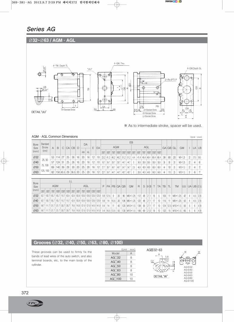
Ø32~Ø63 / AGM·AGL
Series AG
372
Grooves (Ø32, Ø40, Ø50, Ø63, Ø80, Ø100)
W W
AG 32AG 40AG 50AG 63AG 80AG 100
A5.8
3.2C2
1.5
4
DETAIL“W”
DETAIL“UU”
AG 32~63
UB
ØUAH7
ØUAH7
UL
4-TM, Depth TL
TA+Standard Stroke
T
TB QB RØD
2-Rc(PT) P
EA EA
PA PB
LA+Standard Stroke
LB+Standard Stroke
LL+Standard Stroke
EB
CA
CA CB
GA
GB
B
4-GM,Depth GL“UU”
4-QM, Thru
U±0.02
QAS SBSA
These grooves can be used to firmly fix the
bands of lead wires of the auto switch, and also
terminal boards, etc, to the main body of the
cylinder.
Model A
AG□32 8
AG□40 8
AG□50 8
AG□63 8
AG□80 10
AG□100 10
(Unit : mm)
AGM·AGL Common Dimensions
Ø32 53 114 27 25 26 16 20 16 12 10
Ø40 57 124 31 25 26 16 20 16 12 10
Ø50 69 140 39 29 30 20 25 20 16 12
Ø63 82 150 45.5 29 36.5 20 25 20 16 12
23.2 41.2 46.2 46.2 51.2 51.2 4.4 41.4 46.4 46.4 66.4 66.4 38 80 20 M8×1.25 22 37.5 59.5
16.7 34.7 39.7 39.7 44.7 44.7 0 34.9 39.9 39.9 59.9 59.9 38 90 20 M8×1.25 22 44 66
27.7 39.7 49.7 49.7 54.7 54.7 2.9 44.9 49.9 49.9 69.9 69.9 44 100 25 M10×1.5 22 44 72
22.7 34.7 44.7 44.7 49.7 49.7 0 39.9 44.9 44.9 64.9 64.9 44 110 25 M10×1.5 31 49 77
A B C CA CB D E EA
25, 50
75, 100
125, 150
25ST 50ST 75ST 100ST 125ST 150ST 25ST 50ST 75ST 100ST 125ST 150ST
※ As to intermediate stroke, spacer will be used.
(Unit : mm)
BoreSize(mm)
StandardStroke(mm)
DAAGM AGL
AGM AGL
EB
GA GB GL GM I LA LB
Ø32 82.7 100.7 105.7 105.7 110.7 63.9 63.9 100.9 105.9 105.9 125.9 125.9
Ø40 82.7 100.7 105.7 105.7 110.7 110.7 63.9 100.9 105.9 105.9 125.9 125.9
Ø50 99.7 111.7 121.7 121.7 126.7 126.7 74.9 116.9 121.9 121.9 141.9 141.9
Ø63 99.7 111.7 121.7 121.7 126.7 126.7 74.9 116.9 121.9 121.9 141.9 141.9
1/8 12.5 9 30 96 M8×1.25 112 48 2 1 16 5 100 11 M8×1.25 42 4 4.5 3 6
1/8 14 10.5 30 106 M8×1.25 122 48 2 1 17 10 110 11 M8×1.25 50 4 4.5 3 6
1/4 14 11 40 120 M10×1.5 138 56 2 1 17 10 124 12.5 M10×1.5 56 5 6 4 8
1/4 16.5 13.5 50 130 M10×1.5 148 69 2 0 19 10 132 15 M10×1.5 66 5 6 4 8
25ST 50ST 75ST 100ST 125ST 150ST 25ST 50ST 75ST 100ST 125ST 150ST
BoreSize(mm)
AGM AGL
LL
P PA PB QA QB QM R S SA SB T TA TB TL TM UU UA UB UC UL
369-381-AG 2012.9.7 2:59 PM 페이지372 한국원색인쇄사
Series AG
373www.TPCpage.com
www.TPCpneumatics.com
AQADQ
ACP
APM
AS
AX
AM2
AM
ALALX
AQ2ADQ2
AJAJM
ABK
ACK1
NSK
AG
NGQ
AGXGX
NP
ADR
AMR
NDM
ARD
NST
AST
ASTH
NLCD
NLCS
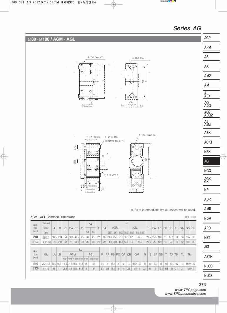
Ø80~Ø100 / AGM·AGL
Bore
Size
(mm)
Ø80
Ø100
Bore
Size
(mm)
Ø80
Ø100
※As to intermediate stroke, spacer will be used.
(Unit : mm)AGM·AGL Common Dimensions
Standard
Stroke
(mm)
A B C CA CB D
GM LA LB P PA PB PC QA QB QM R S SA SB T TA TB TL TM
LL
AGM AGL
F FA FB FC FD FL GA GB GLE EA
EB
AGM AGL
25ST 50ST 75,100ST 125,150ST 25,50ST 75,100,125,150ST
25ST 50ST 75,100ST 125,150ST 25,50ST 75,100,125,150ST
AGM
DA
AGL
96.5 204 50 38.5 46.5 25 30 25 22 18 23.3 25.3 53.3 58.3 8.5 72.5 20.5 15.5 100 11
114.5 238 58 41 56.5 30 36 30 25 20 18.8 23.8 48.8 53.8 4.0 73.0 20.5 25 120 13
M12×1.75 56.5 96.5 119.8 121.8 149.8 154.8 105 169 3/8 19 15.2 28 60 174 M12×1.75 198 80 6.5
M14×2 66 111 129.8 134.8 159.8 164.8 115 184 3/8 22.5 18.8 35 64 200 M14×2 231 95 9
10 20.5 15.5 182 18 M12×1.75
10.5 20.5 25 211 21 M14×2
17.5 11 56 155 30
20 13 62 184 35
25,50,75
100,125,150
F 4-ØFC, ThruFA+Stroke
4-TM, Depth TL 4-QM, Thru
TA+Standard Stroke
TB RQB
SA
T
S
QA
SB
4-GM, Depth GL
C.BØFD, Depth FL
2-Rc(PT) P
PA PB
E EA
EB
FB
BGB
GA
CA CB
CA
PC
ØD
ØDA
LA+Standard Stroke
LB+Standard Stroke
LL+Standard Stroke
369-381-AG 2012.9.7 2:59 PM 페이지373 한국원색인쇄사
Series AG
374
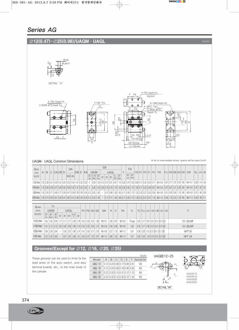
Ø12(0.47)~Ø25(0.98)/UAGM·UAGL
Grooves(Except for Ø12, Ø16, Ø20, Ø25)
A B C CACB D DB E EA
Ø12(1/2 Nom.) 1.02 2.36 0.51 0.49 0.51 0.24 0.32 0.24 1.81 0.32 0.20
Ø16(5/8 Nom.) 1.18 2.64 0.59 0.57 0.59 0.32 0.39 0.32 1.97 0.32 0.20
Ø20(3/4 Nom.) 1.42 3.35 0.71 0.69 0.71 0.39 0.47 0.39 2.28 0.39 0.24
Ø25(1 Nom.) 1.65 3.74 0.83 0.81 0.83 0.47 0.63 0.51 2.68 0.39 0.24
0 0.20 1.34 0.12 0.51 0.51 0.91 1.10 0.28 0.79 1.58 0.98 0.17 0.32 0.53 0.71 M5×0.8
0 0.20 1.34 0.20 0.79 0.79 1.18 1.38 0.28 0.95 1.73 1.06 0.17 0.32 0.49 0.87 M5×0.8
0.12 0.20 1.85 - 0.47 0.98 1.38 1.65 0.71 0.95 1.73 1.22 0.22 0.37 0.53 0.95 M5×0.8
0.12 0.20 1.85 - 0.71 0.71 1.46 1.89 0.71 0.95 1.73 1.38 0.22 0.37 0.57 1.18 M6×1.0
DA
UAGM UAGL 30STLess
30·50STBetween
50STAbove 10ST 20ST 30ST
40·50ST
50STAbove
UAGM·UAGL Common Dimensions
These grooves can be used to frmly fix the
lead wires of the auto switch, and also
terminal boards, etc., to the main body of
the cylinder.
Model A B C D E F Applicable Bolt
UAG*12 0.14 0.24 0.08 0.17 0.06 0.91 M3
UAG*16 0.15 0.24 0.08 0.18 0.06 0.95 M3
UAG*20 0.22 0.33 0.14 0.31 0.12 1.10 M5
UAG*25 0.22 0.33 0.14 0.32 0.12 1.34 M5
(inch)
4-TM, Depth TL
FA
4-QM, Thru
4-FM, Depth FLL
(option)
“U”
C’Bore фFD,Depth FL
4-ØFC, Thru
UC
QA
S
FAF
EA
E PA PB
EB
GA
CA CB
C
A
UD
UU
QB R
FB
ØUB
ØUAH7
DB
FB
ØD
фDA
B
GD
GB
GC
LA+Stroke
LB+Stroke
LL+Stroke
4-GM,Depth GL
F
W W
UAG 12UAG 16UAG 20UAG 25B
F
A
E
D
C
DETAIL“W”
UAG 12~25
Boremm(inch)
EB
UAGLUAGMFA
30STAbove
30STLess
F FB FC FD FL FH FM FLL GAGB GCGD GM GL LA LB
0.47 0.71 1.97 0.91 M3 M4×0.7 0.39 1.14 1.65
0.47 0.87 2.21 0.95 M3 M5×0.8 0.47 1.30 1.81
0.51 0.95 2.84 1.10 M5 M5×0.8 0.51 1.46 2.09
0.59 1.18 3.23 1.34 M5 M6×1.0 0.59 1.48 2.11
1.65 1.85 2.99 1.77 2.17 2.17 2.56 2.76 0.43 0.33 0.55 1.89 M4×0.7 2.28 0.87 M5×0.8 Through 0.24 0.17 0.91 0.12 0.14 0.12 0.24
1.81 2.13 3.15 2.00 2.60 2.60 2.99 3.19 0.43 0.32 0.63 2.13 M5×0.8 2.56 0.98 M5×0.8 0.39 0.24 0.17 0.95 0.12 0.14 0.12 0.24
2.09 2.28 3.94 - 2.56 3.07 3.46 3.74 0.41 0.35 0.71 2.76 M5×0.8 3.27 1.18 M6×1.0 0.47 0.28 0.32 1.10 0.12 0.14 0.12 0.24
2.22 2.30 3.96 - 2.81 2.81 3.56 4.0 0.45 0.37 1.02 3.07 M6×1.0 3.66 1.50 M6×1.0 0.47 0.28 0.32 1.34 0.16 0.18 0.12 0.24
30STLess
50STAbove
40STBetween
10ST 20ST 30ST40~50ST 50ST
Boremm(inch)
LL
UAGLUAGM PA PB QA QB QM R S TM TL TD TLL UU UA UB UC UD P
2-P
F FA
DETAIL “U”
※As to intermediate stroke, spacer will be used.(inch)
Ø12(1/2 Nom.)
Ø16(5/8 Nom.)
Ø20(3/4 Nom.)
Ø25(1 Nom.)
(inch)
C’BORE ØTD Depth TLL
10-32UNF
10-32UNF
NPT1/8
NPT 1/8
369-381-AG 2012.9.7 2:59 PM 페이지374 한국원색인쇄사
Series AG
375www.TPCpage.com
www.TPCpneumatics.com
AQADQ
ACP
APM
AS
AX
AM2
AM
ALALX
AQ2ADQ2
AJAJM
ABK
ACK1
NSK
AG
NGQ
AGXGX
NP
ADR
AMR
NDM
ARD
NST
AST
ASTH
NLCD
NLCS
Ø32(Nom. 11/4)~Ø63( Nom. 21/2")/UAGM·UAGL
Grooves(Except for Ø32, Ø40, Ø50, Ø63)
UAGM·UAGL Common Dimensions
W W
UAG 32UAG 40UAG 50UAG 63UAG 80UAG 100
A0.23
0.13C2
0.06
0.16
DETAIL“W”
UAG ф32(Nom. 11/4)~ф63( Nom. 21/2")
Ø32(11/4 Nom.) 2.09 4.49 1.06 0.98 1.02 0.63 0.79 0.63 0.47 0.39
Ø40(11/2 Nom.) 2.24 4.88 1.22 0.98 1.02 0.63 0.79 0.63 0.47 0.39
Ø50(2 Nom.) 2.72 5.51 1.54 1.14 1.18 0.79 0.98 0.79 0.63 0.47
Ø63(21/2 Nom.) 3.23 5.91 1.79 1.14 1.44 0.79 0.98 0.79 0.63 0.47
0.91 1.62 1.82 1.82 2.02 2.02 0.17 1.63 1.83 1.83 2.61 2.61 1.50 3.15 0.79 M8×1.25 0.87 1.48 2.34
0.66 1.37 1.56 1.56 1.76 1.76 - 1.37 1.57 1.57 2.36 2.36 1.50 3.54 0.79 M8×1.25 0.87 1.73 2.60
1.09 1.56 1.96 1.96 2.15 2.15 0.11 1.77 1.96 1.96 2.75 2.75 1.73 3.94 0.98 M10×1.5 0.87 1.73 2.84
0.89 1.37 1.76 1.76 1.96 1.96 - 1.57 1.77 1.77 2.56 2.56 1.73 4.33 0.98 M10×1.5 1.22 1.93 3.03
A B C CA CB D E EA
25, 50
75, 100
125, 150
25ST 50ST 75ST 100ST 125ST 150ST 25ST 50ST 75ST 100ST 125ST 150ST
※For intermediate strokes. Spacers will be used.
(inch)
BoreSizemm(inch)
StandardStroke(mm)
DAUAGM UAGL
UAGM UAGL
EB
GA GB GL GM I LA LB
Ø32(11/4 Nom.) 3.26 3.96 4.16 4.16 4.36 4.36 2.52 3.97 4.17 4.17 4.96 4.96
Ø40(11/2 Nom.) 3.26 3.96 4.16 4.16 4.36 4.36 2.52 3.97 4.17 4.17 4.96 4.96
Ø50(2 Nom.) 3.93 4.40 4.79 4.79 4.99 4.99 2.95 4.60 4.80 4.80 5.59 5.59
Ø63(21/2 Nom.) 3.93 4.40 4.79 4.79 4.99 4.99 2.95 4.60 4.80 4.80 5.59 5.59
NPT1/8〃 0.49 0.35 1.18 3.78 M8×1.25 4.41 1.89 0.08 0.04 0.63 0.20 3.94 0.43 M8×1.25 1.65 0.16 0.18 0.12 0.24
NPT1/8〃 0.55 0.41 1.18 4.17 M8×1.25 4.80 1.89 0.08 0.04 0.67 0.39 4.33 0.43 M8×1.25 1.97 0.16 0.18 0.12 0.24
NPT1/4〃 0.55 0.43 1.58 4.72 M10×1.5 5.43 2.21 0.08 0.04 0.67 0.39 4.88 0.49 M10×1.5 2.21 0.20 0.24 0.16 0.31
NPT1/4〃 0.65 0.53 1.97 5.12 M10×1.5 5.83 2.72 0.08 - 0.75 0.39 5.20 0.59 M10×1.5 2.60 0.20 0.24 0.16 0.31
25ST 50ST 75ST 100ST 125ST 150ST 25ST 50ST 75ST 100ST 125ST 150ST
BoreSizemm(inch)
UAGM UAGL
LL
P PA PB QA QB QM R S SA SB T TA TB TL TM U UA UB UC UL
UB
ØUAH7
ØUAH7
UL
UC
4-TM, Depth TL
TA+Stroke T
TB
QB R
ØD
2-NPTF P
ØDA
EA EA
PA
LA+Stroke
LB+Stroke
LL+Stroke
EB
C
A
CA CB
GA
GB B
4-GM,Depth GL“UU”
4-QM, Thru
U±0.0008
QA
S SBSA
These grooves can be used to firmly fix the lead
wires of the auto switch, and terminal boards,
etc., to the main body of the cylinder.
Model A
UAG□32 0.32
UAG□40 0.32
UAG□50 0.32
UAG□63 0.32
UAG□80 0.39
UAG□100 0.39
(inch)
(inch)
369-381-AG 2012.9.7 2:59 PM 페이지375 한국원색인쇄사
Series AG
376
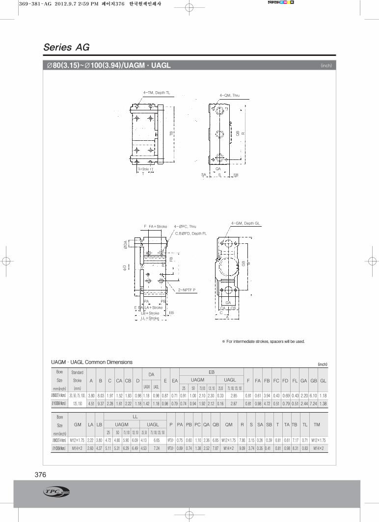
Ø80(3.15)~Ø100(3.94)/UAGM·UAGL
Bore
Size
mm(inch)
Ø80(31/4 Nom.)
Ø100(4 Nom.)
Bore
Size
mm(inch)
Ø80(31/4 Nom.)
Ø100(4 Nom.)
※ For intermediate strokes, spacers will be used.
(inch)UAGM·UAGL Common Dimensions
F 4-ØFC, ThruFA+Stroke
4-TM, Depth TL4-QM, Thru
(inch)
TA+StrokeTB RQB
SA
T
S
QA
SBT
4-GM, Depth GL
C.BØFD, Depth FL
2-NPTF P
PA PB
E EA
EB
FB
BGB
GA
CA CB
CA
PC
фD
ØDA
LA+Stroke
LB+Stroke
LL+Stroke
Standard
Stroke
(mm)
A B C CA CB D
GM LA LB P PA PB PC QA QB QM R S SA SB T TA TB TL TM
LL
UAGM UAGL
F FA FB FC FD FL GA GB GLE EA
EB
UAGM UAGL
25 50 75,100 125, 150 25,50 75, 100, 125, 150
25 50 75, 100 125, 150 25, 50 75, 100, 125, 150
UAGM
DA
UAGL
3.80 8.03 1.97 1.52 1.83 0.98 1.18 0.98 0.87 0.71 0.91 1.00 2.10 2.30 0.33 2.85 0.81 0.61 3.94 0.43
4.51 9.37 2.28 1.61 2.22 1.18 1.42 1.18 0.98 0.79 0.74 0.94 1.92 2.12 0.16 2.87 0.81 0.98 4.72 0.51
M12×1.75 2.22 3.80 4.72 4.80 5.90 6.09 4.13 6.65 NPT3/8〃 0.75 0.60 1.10 2.36 6.85 M12×1.75 7.80 3.15 0.26
M14×2 2.60 4.37 5.11 5.31 6.29 6.49 4.53 7.24 NPT3/8〃 0.89 0.74 1.38 2.52 7.87 M14×2 9.09 3.74 0.35
0.39 0.81 0.61 7.17 0.71 M12×1.75
0.41 0.81 0.98 8.31 0.83 M14×2
0.69 0.43 2.20 6.10 1.18
0.79 0.51 2.44 7.24 1.38
20, 50, 75, 100,
125, 150
369-381-AG 2012.9.7 2:59 PM 페이지376 한국원색인쇄사
Series AG
377www.TPCpage.com
www.TPCpneumatics.com
AQADQ
ACP
APM
AS
AX
AM2
AM
ALALX
AQ2ADQ2
AJAJM
ABK
ACK1
NSK
AG
NGQ
AGXGX
NP
ADR
AMR
NDM
ARD
NST
AST
ASTH
NLCD
NLCS
Auto Switch Model W4
Application Relay, Sequence Control
Voltage
Range of Load Current
Protection Circuit for Contact Breaker Point None
Internal Voltage Drop 2.4V or less
Indicator Lamp ON:Red light emitting diode
Auto Switch Specifications
•Leakage current - None
•Response time - 1.2 ms
•Lead Wire - Oil proof vinyl Ø3.4, 0.2mm2, 2 wire(red, black), 0.5 m
•Impact Resistance - 30G
•Insulation Resistance - 50MΩor more under the test voltage
500VDC (Between case and cable)
•Breakdown Voltage - 1500VAC 1min(between case and cable)
•Ambient Temperature - 5~60℃
•Protection Structure - IEC spec IP67, Water-proof(JISC 0920), oil-proof.
※ If 3m lead wire is required, L is put at end of model numbers.
(Example) W4L
DC24V AC110V
5~40mA 5~20mA
Auto Switch DimensionsAuto Switch/Internal Circuit
(0.13)
Ø3.4
11.7(0.46)
6.2
(0.24)
3(0.12)
14(0.55)
6 4
(0.24) (0.16)
Ø3.2(0.13)
22(0.87)
ℓ
8.5(0.33)
Indicator Lamp
Operating Range(See List Below)
Most Sensitive Position
Ø8(0.31)
Red
Black
Light emitting
Zener diode
Reed switch (+)
(-)
mm(inch)
Operating Range (ℓDimensions)
SeriesBore Size inch(mm)
mm(inch)
UAG12
(0.47)
11
(0.43)
10
(0.39)
12
(0.47)
12
(0.47)
13
(0.51)
Ø32(41/4Nom.) Ø40(11/2Nom.) Ø50(2Nom.) Ø63(21/2Nom.) Ø80(31/4Nom.) Ø100(4Nom.)
369-381-AG 2012.9.7 2:59 PM 페이지377 한국원색인쇄사
Series AG
378
Protection Structure
Operating Range
Section W13 W1HN(P)
Most sensitive position(S) 10mm 1 ~ 2mm
Operation range(L) 6 ~ 12mm 4 ~ 10mm
■Caution
Plase read and understand the
instructions before use. Refer to the auto
switch precautions before using auto
switches.
Part No. W13 W1HN(P)
Contact wiring Contact 2 wire Without contact 3 wire
Application Relay, Sequence Control
Voltage DC24V AC100V DC24V
Current 5~40mA 5~20mA ≦40mA
Contact Protection Circuit None Built-in
Internal Voltage Drop ≦2.4V ≦1.5V
Indicator Lamp ON : When Red LED
Output - NPN(PNP)
Current Consumption - ≦5mA
Current Leakage None ≦100㎂
Operation Time ≦1ms ≦2ms
Lead Wire Oil Resistant Vinyl Code
Shock Resistance 30G 100G
Insulation Resistance 100㏁ or more (500DVC Mega) between lead wire and case
Voltage Resistance For 1 min.(in AC1500V/between a lead wire case)
Temperature -10 ~ 60℃
Protection Structure IEC Standard IP67, Water Proof, and(JISC0920),Oil Structure
Specifications
1⃞ TPC Auto Switch Model
2⃞ 3 : Reed 2 wire AUTO S/WH : Solid State 3 wire AUTO S/W
3⃞ N: 3 wire(NPN)P : 3 wire(PNP)
4⃞Blank : LEAD WIRE(0.5m)M : LEAD WIRE(1m) L : LEAD WIRE(3m)
W11 2
*
3
*
4
*
How to Order
Internal Circuit
2 wire reed circuit
Brown(+)
Brown(+)
Main Circuit ofSwitch
Main Circuit ofSwitch
Black(S)
Black(S)
(Slotted set screw)
Indicator Lamp
Operating range
Most sensitive position
Blue(-)
Blue(-)
3 wire NPN solid state circuit
3 wire NPN solid state circuit
Blue(-)
Brown(+)
369-381-AG 2012.9.7 2:59 PM 페이지378 한국원색인쇄사
Operating Conditions
Series AG
379www.TPCpage.com
www.TPCpneumatics.com
AQADQ
ACP
APM
AS
AX
AM2
AM
ALALX
AQ2ADQ2
AJAJM
ABK
ACK1
NSK
AG
NGQ
AGXGX
NP
ADR
AMR
NDM
ARD
NST
AST
ASTH
NLCD
NLCS
Permissible Rotary Torque of Plate(T)
Permissible Lateral Load (F)
Stroke(mm)
10 20 30 40 50 75 100
AGM 26 20 18 18 17 29 25
AGL 24 36 29 40 34 26 20
AGM 42 34 30 28 26 39 34
AGL 36 54 43 58 51 37 30
AGM - 53 47 45 42 88 76
AGL - 39 64 112 100 75 62
AGM - 70 61 60 54 116 100
AGL - 61 50 134 120 98 81
Ø12
Ø16
Ø20
Ø25
ModelBore Size
Stroke(mm)
10 20 30 40 50 75 100
AGM 0.42 0.34 0.28 0.31 0.27 0.48 0.42
AGL 0.51 0.88 0.75 1.06 0.96 0.78 0.64
AGM 0.76 0.64 0.54 0.52 0.47 0.73 0.62
AGL 0.82 1.43 1.23 1.64 1.52 1.23 1.06
AGM - 1.14 1.02 0.98 0.80 1.90 1.65
AGL - 1.14 2.03 3.40 3.19 2.65 2.32
AGM - 1.79 1.58 1.53 1.38 2.96 2.57
AGL - 2.10 1.86 4.74 4.46 4.01 3.53
Ø12
Ø16
Ø20
Ø25
Model
1N≑0.102kgf
1N·m≑10.2kgf.cm
Units : N
Stroke(mm)
25 50 75 100 125 150
AGM 196 167 137 108 91 76
AGL 88 59 275 216 239 223
AGM 196 167 137 108 91 76
AGL 88 59 275 216 239 293
AGM 294 255 215 176 151 130
AGL 137 88 392 313 313 294
AGM 294 255 215 176 151 130
AGL 137 88 392 313 313 294
AGM 353 304 255 206 - -
AGL 235 157 863 686 - -
AGM 539 470 412 343 - -
AGL 470 313 1370 1070 - -
Ø32
Ø40
Ø50
Ø63
Ø80
Ø100
Model
1N≑0.102kgf
Units : N
Stroke(mm)
25 50 75 100 125 150
AGM 3.92 2.94 2.45 1.96 1.47 1.03
AGL 1.96 0.98 5.88 4.41 5.76 5.12
AGM 4.41 3.43 2.94 2.45 1.84 1.35
AGL 2.45 1.47 6.37 5.39 6.87 6.17
AGM 7.35 5.88 4.90 4.41 3.31 2.41
AGL 3.43 2.45 10.78 8.33 9.63 8.63
AGM 7.84 6.37 5.39 4.90 3.60 2.59
AGL 3.92 2.45 11.76 9.31 9.61 8.51
AGM 11.76 9.80 7.84 6.86 - -
AGL 9.31 5.88 31.36 24.50 - -
AGM 22.54 19.60 16.66 14.70 - -
AGL 21.56 13.72 63.70 49.00 - -
Ø32
Ø40
Ø50
Ø63
Ø80
Ø100
Model
1N≑0.102kgf
Units : N·m
Units : N·m
F
F
T : (N·m)
Bore Size
Bore Size
Bore Size
369-381-AG 2012.9.7 2:59 PM 페이지379 한국원색인쇄사
Operating Range When Used as Stopper
Series AG
380
AGM32~100
Bore SizeNon-Rotation Accuracy
AGM AGL
Ø12
Ø16
Ø20
Ø25
Ø32
Ø40
Ø50
Ø63
Ø80
Ø100
±0.06° ±0.08°
±0.05° ±0.06°
±0.04° ±0.05°
±0.07° ±0.10°
±0.06° ±0.09°
AGM12~25
※ When selecting the machine type, if the
dimension gets longer, select a certain cylinder
having a sufficient bore.
Note 1) When a stopper is used for the cylinder,
use at 50 strokes or less.
Note 2) AGL(Ball bush bearing) should not be
used as stopper.
※ When selecting the machine type, if the
dimension gets longer, select a certain cylinder
having a sufficient bore.
Note 1) When a stopper is used for the cylinder,
use at 50 strokes or less.
Note 2) AGL(Ball bush bearing) should not be
used as stopper.
Bore Size Ø12~Ø25 / AGM12~25(Slide Bearing)
Bore Size Ø32~Ø100 / AGM32~100(Slide Bearing)
υ
ℓ≑50mm
ℓ≑50mm υ
WW
1,500
1,000
900
800
700
600
500
400
300
200
100
040 30 20 10
Ø100
Ø80
Ø63
Ø50
Ø40
Ø32
Transportation speed υ(m/min)
Weight transported work mm(kgf)
υ
ℓ≑50mm
ℓ≑50mm υ
90
80
70
60
50
40
30
20
10
0
30 20 10
Ø25
Ø20
Ø16
Ø12
Transportation speed υ(m/min)
Weight transported work mm(kgf) M M
369-381-AG 2012.9.7 2:59 PM 페이지380 한국원색인쇄사
Operating Range When Used as Lifter
Series AG
381www.TPCpage.com
www.TPCpneumatics.com
AQADQ
ACP
APM
AS
AX
AM2
AM
ALALX
AQ2ADQ2
AJAJM
ABK
ACK1
NSK
AG
NGQ
AGXGX
NP
ADR
AMR
NDM
ARD
NST
AST
ASTH
NLCD
NLCS
Bore Size Theoretical Output
Ø12, Ø16 40% or Below
Ø20, Ø25 50% or Below
Ø32, Ø100 60% or Below
AGM Ø12~Ø25- AGL Ø12~Ø25-30 more stroke
AGL Ø32~Ø105- AGL Ø32~Ø100-AGM Ø32~Ø100
AGL Ø12~Ø25- 102030
75100
●Be sure to select a proper bore size so that themass remains at or below the theoretical output(refer to the chart below)
Wℓ ℓ
W
AGM/Slide Bearing AGL/Ball Bush Bearing
2500
2000
1500
1000
5004003002001000
150
140
130
120
110
100
90
80
70
60
50
40
30
20
10
0150 100 50
150 100 50 150 100 50 200 150 100 50
150 100 50 150 100 50
Ø25
P=0.5MPa
Ø20
Ø16
Eccentric Length l (mm)
Ø12
Eccentric load W(N)
150
140
130
120
110
100
90
80
70
60
50
40
30
20
10
0
Ø25
P=0.5MPa
Ø20
Ø16
Eccentric Length l (mm)
Ø12
Eccentric load W(N)
2500
2000
1500
1000
500
400
300
200
100
0
Ø100
Ø63
P=0.5MPa
Ø80
Ø50
Eccentric Length l (mm)
Ø40
Ø32
Eccentric load W(N)
Ø100
Ø63
P=0.5MPa
Ø80
Ø50
Eccentric Length l (mm)
Ø40
Ø32
Ø100
Ø63
P=0.5MPa
Ø80
Ø50
Eccentric Length l (mm)
Ø40
Ø32
Eccentric load W(N)
150
140
130
120
110
100
90
80
70
60
50
40
30
20
10
0
Ø25
P=0.5MPa
Ø20
Ø16
Eccentric Length l (mm)
Ø12
Eccentric load W(N)
2500
2000
1500
1000
5004003002001000
Eccentric load W(N)
2550
369-381-AG 2012.9.7 2:59 PM 페이지381 한국원색인쇄사