Embed Size (px)
Citation preview
Page 1 Web: www.maxbotix.com
PD11838n
MaxBotix ® Inc.
Copyright 2005 - 2017 MaxBotix Incorporated Patent 7,679,996
XL-MaxSonar ® - WR/WRC™
Series
MaxBotix Inc., products are engineered and assembled in the USA
XL-MaxSonar ®- WR/WRC™ Series High Performance, IP67 Weather Resistant, Ultrasoni c Range Finder MB7051, MB7052, MB7060, MB7062, MB7066, MB7067, MB7 068, MB7070, MB7072, MB7076, MB7077, MB7078, MB7092 3
Features • Real-time auto calibration and noise
rejection • High acoustic power output • Precise narrow beam • Object detection includes zero range
objects • 3V to 5.5V supply with very low
average current draw • Free run operation can continually
measure and output range information • 10Hz refresh rate (MB7060,
MB7062, MB7066, MB7070, MB7072, MB7076, MB7092) • 6.6Hz refresh rate (MB7052) • 5.1Hz refresh rate (MB7051) • Triggered operation provides the
range reading as desired • All interfaces are active
simultaneously • RS232 Serial, 0 to Vcc, 9600 Baud,
81N
• Analog, (Vcc/1024) / cm for standard models • Analog, (Vcc/1024) / 2cm for
10-meter models (MB7051, MB7066, MB7076) • Sensor operates at 42KHz
Benefits • Acoustic and electrical noise
resistance • Reliable and stable range data • Robust, low cost IP67 standard
sensor • Narrow beam characteristics • Very low power excellent for battery
based systems • Ranging can be triggered externally
or internally • Sensor reports the range reading
directly, frees up user processor • Easy hole mounting or mating with
standard electrical fittings • Filtering allows very reliable
operation in most environments
Applications and Uses • Tank level measurement • Bin level measurement • Proximity zone detection • Environments with acoustic and
electrical noise • Distance measuring • Long range object detection • Super high sensitivity for long range
small object detection (MB7051) • Industrial sensor -40°C to +65°C
(limited operation to +85°C) 2 Notes: 1 Minimum distance is 25cm for the MB7051, MB7052, MB7092 2 Please reference page 14 for minimum operating voltage verses temperature information 3 Please reference page 23 for part number key
The XL-MaxSonar-WR and XL-MaxSonar-WRC sensor series provide users with robust range information in air. These sensors also feature high-power acoustic output along with real-time auto calibration for changing conditions (supply voltage sag, acoustic noise, or electrical noise), operation with supply voltage from 3V to 5.5V, object detection from 0-cm to 765-cm (select models) or 1068-cm (select models), and sonar range information from 20-cm1 out to 765-cm (select models) or 1068-cm (select models) with 1-cm resolution. Objects from 0-cm to 20-cm1 range as 20-cm1 or closer. The sensor is housed in a robust PVC housing, designed to meet the IP67 water intrusion standard, and matches standard electrical/water ¾” PVC pipe fittings. The user interface formats included are pulse-width (select models), real-time analog-voltage envelope (select models), analog voltage output, and serial output.
Close Range Operation Applications requiring 100% reading-to-reading reliability should not use MaxSonar sensors at a distance closer than 20cm1. Although most users find MaxSonar sensors to work reliably from 0 to 20cm1 for detecting objects in many applications, MaxBotix® Inc. does not guarantee operational reliability for objects closer than the minimum reported distance. Because of ultrasonic physics, these sensors are unable to achieve 100% reliability at close distances. Warning: Personal Safety Applications We do not recommend or endorse this product be used as a component in any personal safety applications. This product is not designed, intended or authorized for such use. These sensors and controls do not include the self-checking redundant circuitry needed for such use. Such unauthorized use may create a failure of the MaxBotix® Inc. product which may result in personal injury or death. MaxBotix® Inc. will not be held liable for unauthorized use of this component.
1 25cm (MB7051, MB7052, MB7092)
1 25cm (MB7051, MB7052, MB7092)
Page 2 Web: www.maxbotix.com
PD11838n
MaxBotix ® Inc.
Copyright 2005 - 2017 MaxBotix Incorporated Patent 7,679,996
XL-MaxSonar ® - WR/WRC™
Series
MaxBotix Inc., products are engineered and assembled in the USA
XL-MaxSonar-WR/WRC Pin Out Pin 1- Leave open (or high) for serial output on the Pin 5 output. When Pin 1 is held low the Pin 5 output sends a pulse (instead of serial data), suitable for low noise chaining.
Pin 2- This pin outputs a pulse-width representation of range. To calculate the distance, use a scale factor of 58uS per cm. (MB7051, MB7052, MB7060, MB7062, MB7066, MB7067, MB7068)
This pin outputs the analog voltage envelope of the acoustic waveform. For the MB7070 series and MB7092 sensors, this is a real-time always-active output (MB7070, MB7072, MB7076, MB7077, MB7078, MB7092)
Pin 3- AN-This pin outputs analog voltage with a scaling factor of (Vcc/1024) per cm. A supply of 5V yields ~4.9mV/cm., and 3.3V yields ~3.2mV/cm. Hardware limits the maximum reported range on this output to ~700 cm at 5V and ~600 cm at 3.3V. The output is buffered and corresponds to the most recent range data.
For the 10-meter sensors (MB7051, MB7066, MB7076) Pin 3 outputs an analog voltage with a scaling of (Vcc/1024) per 2cm. A supply of 5V yields ~4.9mV/2cm., and 3.3V yields ~3.2mV/2cm. This Analog Voltage output steps in 2cm increments.
Pin 4- RX- This pin is internally pulled high. If Pin-4 is left unconnected or held high, the sensor will continually measure the range. If Pin-4 is held low the sensor will stop ranging. Bring high 20uS or more to command a range reading.
Pin 5- TX- When Pin 1 is open or held high, the Pin 5 output delivers asynchronous serial data in an RS232 format, except the voltages are 0-Vcc. The output is an ASCII capital “R”, followed by ASCII character digits representing the range in centimeters up to a maximum of 765 (select models) or 1068 (select models), followed by a carriage return (ASCII 13). The baud rate is 9600, 8 bits, no parity, with one stop bit. Although the voltages of 0V to Vcc are outside the RS232 standard, most RS232 devices have sufficient margin to read the 0V to Vcc serial data. If standard voltage level RS232 is desired, invert, and connect an RS232 converter such as a MAX232.When Pin 1 is held low, the Pin 5 output sends a single pulse, suitable for low noise chaining (no serial data).
V+ Operates on 3V - 5.5V. The average (and peak) current draw for 3.3V operation is 2.1mA (50mA peak) and 5V operation is 3.4mA (100mA peak) respectively. Peak current is used during sonar pulse transmit. Please reference page 14 for minimum operating voltage verses temperature information.
GND-Return for the DC power supply. GND (& V+) must be ripple and noise free for best operation.
_______________________________________________________________________________________________________________________________________
About Ultrasonic Sensors Our ultrasonic sensors are desired for use in air, non-contact object detection and ranging sensors that detect objects within a defined area. These sensors are not affected by the color or other visual characteristics of the detected object. Ultrasonic sensors use high frequency sound to detect and localize objects in a variety of environments. Ultrasonic sensors measure the time of flight for sound that has been transmitted to and reflected back from nearby objects. Based upon the time of flight, the sensor then outputs a range reading.
_____________________________________________________________________________________________________________________________________
Auto Calibration Each time before the XL-MaxSonar-WR takes a range reading it auto calibrates. The sensor then uses this data to range objects. If the temperature, humidity, or applied voltage changes during sensor operation, the sensor will continue to function normally. (The sensors do not apply compensation for the speed of sound change verses temperature to any range readings.) If the application requires temperature compensation please look at the HRXL-MaxSonar-WR sensor line.
_______________________________________________________________________________________________________________________________________
Supply Voltage Compensation During power up, the XL-MaxSonar-WR sensor line will calibrate itself for the supply voltage. Additionally, the sensor will compensate if the supplied voltage gradually changes.
If the average voltage applied to the sensor changes faster than 0.5V per second, it is best to remove and reapply power to the sensor. For best operation, the sensor requires noise free power. If the sensor is used with noise on the supplied power or ground, the accuracy of the readings may be affected. Typically, adding a 100uF capacitor at the sensor between the V+ and GND pins will correct most power related electrical noise issues.
Page 3 Web: www.maxbotix.com
PD11838n
MaxBotix ® Inc.
Copyright 2005 - 2017 MaxBotix Incorporated Patent 7,679,996
XL-MaxSonar ® - WR/WRC™
Series
MaxBotix Inc., products are engineered and assembled in the USA
Real-time Auto Calibration The XL-MaxSonar-WR automatically calibrates prior to each range reading. The sensor then uses this data to range objects. If the temperature, humidity, or applied voltage changes during sensor operation, the sensor will continue to function normally. (The sensors do not apply compensation for the speed of sound change verses temperature to any range readings.) Detection has been characterized in the published sensor beam patterns.
_______________________________________________________________________________________________________________________________________
Real-time Noise Rejection While the XL-MaxSonar-WR is designed to operate in the presence of noise, best operation is obtained when noise strength is low and desired signal strength is high. Hence, the user is encouraged to mount the sensor in such a way that minimizes outside acoustic noise pickup. In addition, keep the DC power to the sensor free of noise. This will let the sensor deal with noise issues outside of the users direct control (Even so, in general, the sensor will still function well even if these things are ignored). Users are encouraged to test the sensor in their application to verify usability.
_______________________________________________________________________________________________________________________________________
Sensor Minimum Distance The XL-MaxSonar-WR sensors have a minimum reported distance of 20-cm1 (7.87 inches). However, the XL-MaxSonar-WR will range and report targets to the front sensor face. Large targets closer than 20-cm1 will typically range as 20-cm1. For the alternative housings, objects between 4-cm and 20-cm will typically range as 20-cm. Note 1: 25cm for the MB7051, MB7052, MB7092
_______________________________________________________________________________________________________________________________________
WR Exposed Materials The exposed materials of a properly mounted MaxSonar WR standard sensor are: Aluminum (oxidized surface), PVC, & silicone rubber (VMQ).
_______________________________________________________________________________________________________________________________________
Additional Options for Purchase Please contact MaxBotix for any additional information regarding the options listed below at [email protected].
F-Option In addition to the standard MaxSonar WR, MaxBotix Inc. has developed the F-Option for additional protection necessary in a few hazardous chemical environments. Extremely corrosive gases or liquids can degrade or compromise the operation of the sensing unit. As a result, we offer a more chemically inert seal which allows our sensors to operate in all but the harshest of chemical environments. In addition to the chemical resistance the sensor has improved performance in wet or dust environments.
Please Note: Our sensors are designed for operation in normal atmosphere (air). Please be aware that the speed of sound and atmospheric attenuation may change as a result of the transmission properties of different chemical/air mediums. Users are strongly encouraged to characterize and test the operation of the sensor in the new medium to verify operation, and properly scale the outputted range information.
The exposed materials of a properly mounted MaxSonar WR sensor with the F-Option added are: Aluminum (oxidized surface), PVC, & Fluorosilicone (with an additional back up FEP Teflon® seal).
Shielded Cable Attach Option For simple integration of our sensors into end-user applications, MaxBotix has developed the Shielded Cable Attach Option to create a completely IP67 rated MaxSonar-WR sensor. The standard Shielded Cable Attach Option uses 3 feet of the MaxSonar MB7954 Shielded Cable (MB7984 when attached by MaxBotix) with an epoxy filled cap to fully protect the pin-out of the MaxSonar sensor. Additional cable length can be specified and purchased using part number MB7984.
P-Option The P-Opiton is a Parylene coating applied to the surface of the aluminum transducer. This helps to improve the corrosion resistance of the aluminum transducer. The exposed materials of a properly mounted MaxSonar WR sensor with the P-Option added are: Parylene, PVC, & silicone rubber (VMQ). The F-Option can be purchased with the P-Option.
Page 4 Web: www.maxbotix.com
PD11838n
MaxBotix ® Inc.
Copyright 2005 - 2017 MaxBotix Incorporated Patent 7,679,996
XL-MaxSonar ® - WR/WRC™
Series
MaxBotix Inc., products are engineered and assembled in the USA
Sensor Descriptions
Base Sensor (MB7060 and MB7070) The MB7060 and MB7070 are the base models of the XL-MaxSonar-WR sensor line. These sensors are recommended for general purpose usage. All other sensors in this series are based off these sensor models. The additional features are mentioned in their respective sections below.
_______________________________________________________________________________________________________________________________________
XL-MaxSonar-WR1 (MB7062 and MB7072) The XL-MaxSonar-WR1 sensors feature a 3 reading stability filter that ranges to the first detectable target. Filtering is available on Pin3 (AN) and Pin 5 (TX). Filtering is not applied to the output on Pin 2 (PW). This filter requires that 3 consecutive range readings are within 1cm of each other to be considered a valid range reading. If the range readings are outside 1cm, the sensor discards the range reading set and reports the last valid range reading. This sensor does not view maximum range as a valid range, and will not report 765 when no target is detected. If this sensor does not detect a target for 1 hour, the sensor will go into fail-safe and report 000.
_______________________________________________________________________________________________________________________________________
XL-MaxSonar-WRL (MB7066 and MB7076) The XL-MaxSonar-WRL will report a maximum distance of 10 meters for large targets.
_______________________________________________________________________________________________________________________________________
XL-MaxSonar-WRM (MB7052 and MB7092) The MB7052 and MB7092 sensors prioritize large targets over both small targets and noise. These sensors report the target that gives the largest acoustic reflection. This stands in contrast to other units such as the MB7060 which are designed to report the distance to the first detectable target. If the largest target is removed from the field of view, the MB7052 and MB7092 will switch to the target that gives the next largest detectable return. When targets are of similar amplitude reflections, preference is given to the closer target. The sensor expects to see a target by 7.56 meters. If no target is found, the sensor will increase in sensitivity until a target is found, or until no targets can be found. In addition to the most-likely filtering, the MB7052 and MB7092 come equipped with a three-reading filter and reading hold which requires three consecutive range readings within 1cm of the most recent reading to be considered a valid range reading. If readings are found to be outside 1cm, or no target can be found by the sensor, then the sensor will report the last valid range reading. Upon power-up the sensor will default to reporting 7.65 meters unit a valid range reading is found. The last reading hold is designed for users operating in environments with intermittent high noise who desire to poll the MB7052 or MB7092 at intermittent times. This allows the sensor to report the previously valid reading until the sensor’s environment improves. If no valid range reading is found for ~1.5 hours, the sensor will send a fail-safe output “000” on all interfaces.
_______________________________________________________________________________________________________________________________________
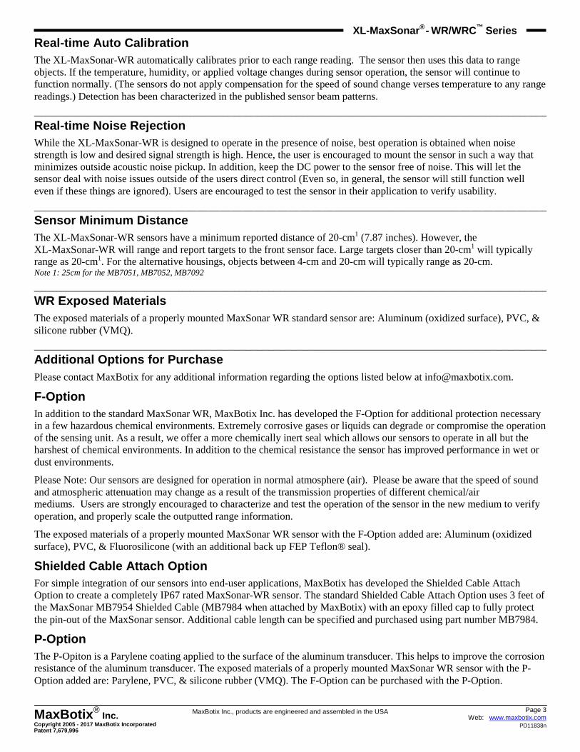
XL-MaxSonar-WRML (MB7051) The MB7051 includes all the features of the MB7052 with a maximum distance of 10 meters which provides a very robust long range sensing solution. The MB7051 is ideal for applications requiring small or soft target detection at longer ranges than our previously mentioned XL-MaxSonar-WR sensors. The MB7051 has improved sensitivity to objects with the addition of a horn extension. This improvement results in the sensor detecting objects of similar size about 2.5 times further in comparison to the MB7066 sensor. The detection patterns of each are shown in the beam pattern section of the datasheet.
Page 5 Web: www.maxbotix.com
PD11838n
MaxBotix ® Inc.
Copyright 2005 - 2017 MaxBotix Incorporated Patent 7,679,996
XL-MaxSonar ® - WR/WRC™
Series
MaxBotix Inc., products are engineered and assembled in the USA
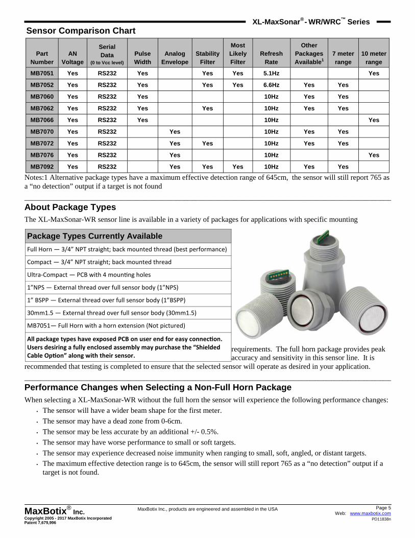
Sensor Comparison Chart
Notes:1 Alternative package types have a maximum effective detection range of 645cm, the sensor will still report 765 as a “no detection” output if a target is not found
_______________________________________________________________________________________________________________________________________
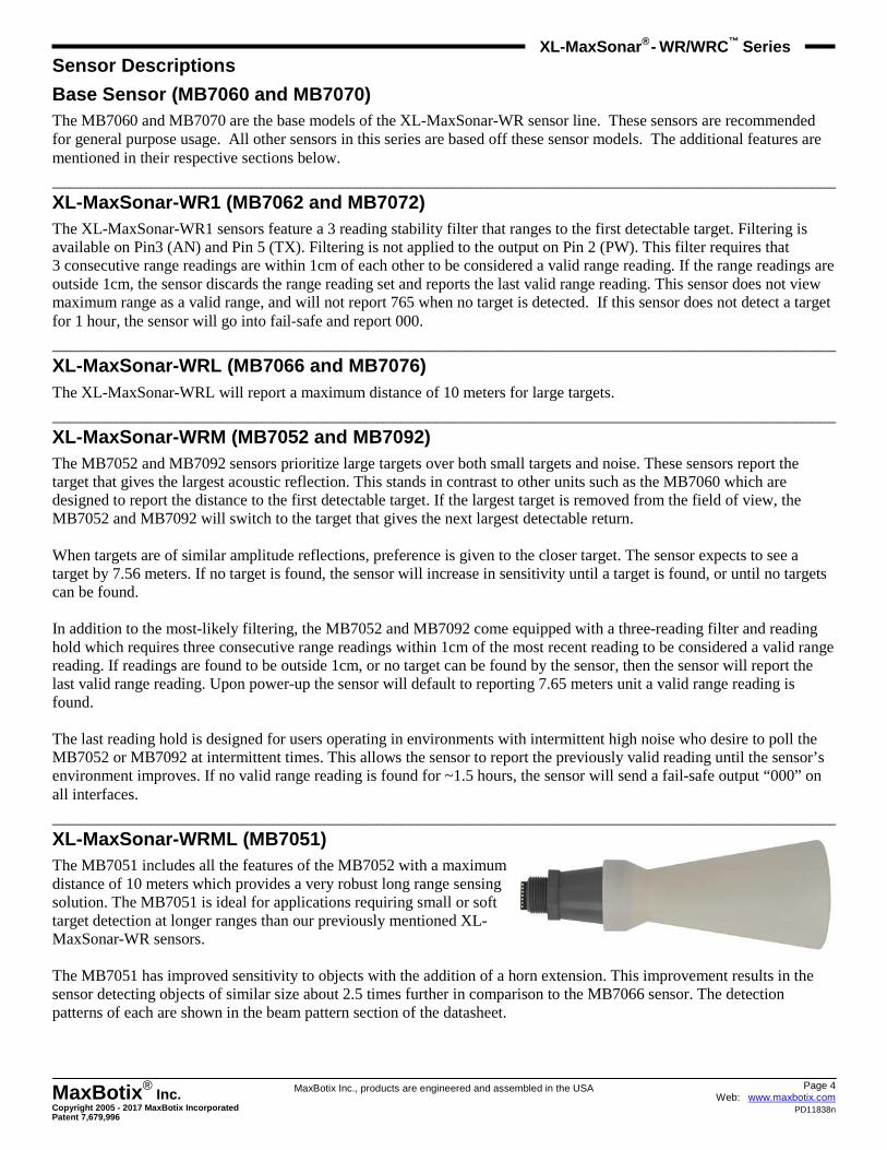
About Package Types The XL-MaxSonar-WR sensor line is available in a variety of packages for applications with specific mounting
requirements. The full horn package provides peak accuracy and sensitivity in this sensor line. It is
recommended that testing is completed to ensure that the selected sensor will operate as desired in your application.
_______________________________________________________________________________________________________________________________________
Performance Changes when Selecting a Non-Full Horn Package When selecting a XL-MaxSonar-WR without the full horn the sensor will experience the following performance changes:
• The sensor will have a wider beam shape for the first meter.
• The sensor may have a dead zone from 0-6cm.
• The sensor may be less accurate by an additional +/- 0.5%.
• The sensor may have worse performance to small or soft targets.
• The sensor may experience decreased noise immunity when ranging to small, soft, angled, or distant targets. • The maximum effective detection range is to 645cm, the sensor will still report 765 as a “no detection” output if a
target is not found.
Part Number
AN Voltage
Serial Data
(0 to Vcc level) Pulse Width
Analog Envelope
Stability Filter
Most Likely Filter
Other Packages Available 1
7 meter range
10 meter range
MB7052 Yes RS232 Yes Yes Yes Yes Yes
MB7060 Yes RS232 Yes Yes Yes
MB7062 Yes RS232 Yes Yes Yes Yes
MB7066 Yes RS232 Yes Yes
MB7070 Yes RS232 Yes Yes Yes
MB7072 Yes RS232 Yes Yes Yes Yes
MB7076 Yes RS232 Yes Yes
MB7092 Yes RS232 Yes Yes Yes Yes Yes
Refresh Rate
6.6Hz
10Hz
10Hz
10Hz
10Hz
10Hz
10Hz
10Hz
MB7051 Yes RS232 Yes Yes Yes 5.1Hz Yes
Package Types Currently Available
Full Horn — 3/4” NPT straight; back mounted thread (best performance)
Compact — 3/4” NPT straight; back mounted thread
1”NPS — External thread over full sensor body (1”NPS)
1” BSPP — External thread over full sensor body (1”BSPP)
30mm1.5 — External thread over full sensor body (30mm1.5)
All package types have exposed PCB on user end for easy connec�on.
Users desiring a fully enclosed assembly may purchase the “Shielded
Cable Op�on” along with their sensor.
Ultra-Compact — PCB with 4 moun0ng holes
MB7051— Full Horn with a horn extension (Not pictured)
Page 6 Web: www.maxbotix.com
PD11838n
MaxBotix ® Inc.
Copyright 2005 - 2017 MaxBotix Incorporated Patent 7,679,996
XL-MaxSonar ® - WR/WRC™
Series
MaxBotix Inc., products are engineered and assembled in the USA
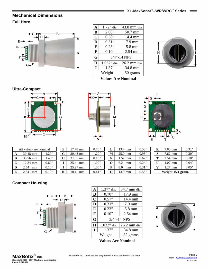
Mechanical Dimensions Full Horn
Ultra-Compact
Compact Housing
A 1.72” dia. 43.8 mm dia. B 2.00” 50.7 mm C 0.58” 14.4 mm D 0.31” 7.9 mm E 0.23” 5.8 mm F 0.10” 2.54 mm
G 3/4”-14 NPS
H 1.032” dia. 26.2 mm dia. I 1.37” 34.8 mm
50 grams Weight
Values Are Nominal
Pin 1
A
B D
C
E
F
G
I H
All values are nominal F 17.78 mm 0.70 ” L 13.4 mm 0.53 ” R 7.80 mm 0.31 ” A 30.48 mm 1.20 ” G 30.48 mm 1.20 ” M 25.0 mm 0.98 ” S 7.62 mm 0.30 ” B 35.56 mm 1.40 ” H 3.180 mm 0.13 ” N 1.57 mm 0.62 ” T 2.54 mm 0.10 ” C 12.24 mm 0.60 ” I 25.40 mm 1.00 ” O 6.20 mm 0.24 ” U 1.07 mm 0.04 ” D 2.540 mm 0.10 ” J 25.27 mm 1.00 ” P 8.00 mm 0.31 ” V 1.27 mm 0.05 ” E 2.540 mm 0.10 ” K 10.40 mm 0.41 ” Q 13.9 mm 0.55 ” Weight 15.1 gram.
F
I H
B G
E D C
A P O
Q
R
S T U
V
N
M
J L K
A 1.37” dia. 34.7 mm dia. B 0.70” 17.9 mm C 0.57” 14.4 mm D 0.31” 7.9 mm E 0.23” 5.8 mm F 0.10” 2.54 mm
G 3/4”-14 NPS
H 1.032” dia. 26.2 mm dia. I 1.37” 34.8 mm
32 grams Weight
Values Are Nominal
I H A
B D
C
E
F
Pin 1
G
Page 7 Web: www.maxbotix.com
PD11838n
MaxBotix ® Inc.
Copyright 2005 - 2017 MaxBotix Incorporated Patent 7,679,996
XL-MaxSonar ® - WR/WRC™
Series
MaxBotix Inc., products are engineered and assembled in the USA
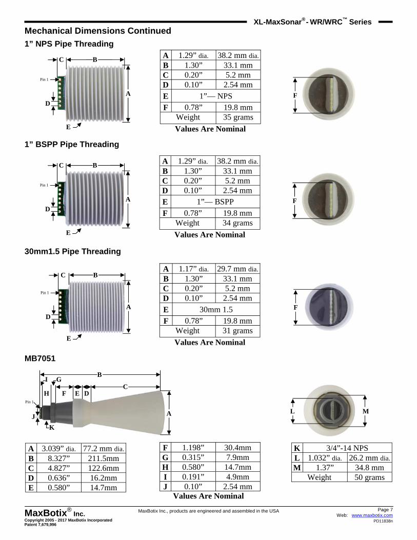
Mechanical Dimensions Continued 1” NPS Pipe Threading
1” BSPP Pipe Threading
30mm1.5 Pipe Threading
MB7051
A 1.17” dia. 29.7 mm dia. B 1.30” 33.1 mm C 0.20” 5.2 mm D 0.10” 2.54 mm
E 30mm 1.5
F 0.78” 19.8 mm
Weight 31 grams
Values Are Nominal
F A
B C
D
Pin 1
E
A 1.29” dia. 38.2 mm dia. B 1.30” 33.1 mm C 0.20” 5.2 mm D 0.10” 2.54 mm
E 1”— NPS
F 0.78” 19.8 mm
Weight 35 grams
Values Are Nominal
F A
B C
D
Pin 1
E
A 1.29” dia. 38.2 mm dia. B 1.30” 33.1 mm C 0.20” 5.2 mm D 0.10” 2.54 mm
E 1”— BSPP
F 0.78” 19.8 mm
Weight 34 grams
Values Are Nominal
F A
B C
D
Pin 1
E
F 1.198” 30.4mm G 0.315” 7.9mm H 0.580” 14.7mm I 0.191” 4.9mm J 0.10” 2.54 mm
Values Are Nominal
M L
J
Pin 1
A
B
D C
E F
G
H
I
K
A 3.039” dia. 77.2 mm dia. B 8.327” 211.5mm C 4.827” 122.6mm D 0.636” 16.2mm E 0.580” 14.7mm
K 3/4”-14 NPS L 1.032” dia. 26.2 mm dia. M 1.37” 34.8 mm
Weight 50 grams
Page 8 Web: www.maxbotix.com
PD11838n
MaxBotix ® Inc.
Copyright 2005 - 2017 MaxBotix Incorporated Patent 7,679,996
XL-MaxSonar ® - WR/WRC™
Series
MaxBotix Inc., products are engineered and assembled in the USA
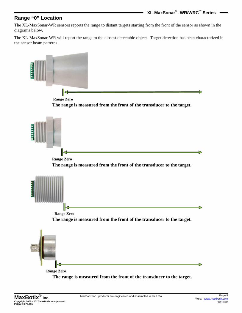
Range “0” Location The XL-MaxSonar-WR sensors reports the range to distant targets starting from the front of the sensor as shown in the diagrams below.
The XL-MaxSonar-WR will report the range to the closest detectable object. Target detection has been characterized in the sensor beam patterns.
The range is measured from the front of the transducer to the target. Range Zero
Range Zero
The range is measured from the front of the transducer to the target.
Range Zero
The range is measured from the front of the transducer to the target.
Range Zero
The range is measured from the front of the transducer to the target.
Page 9 Web: www.maxbotix.com
PD11838n
MaxBotix ® Inc.
Copyright 2005 - 2017 MaxBotix Incorporated Patent 7,679,996
XL-MaxSonar ® - WR/WRC™
Series
MaxBotix Inc., products are engineered and assembled in the USA
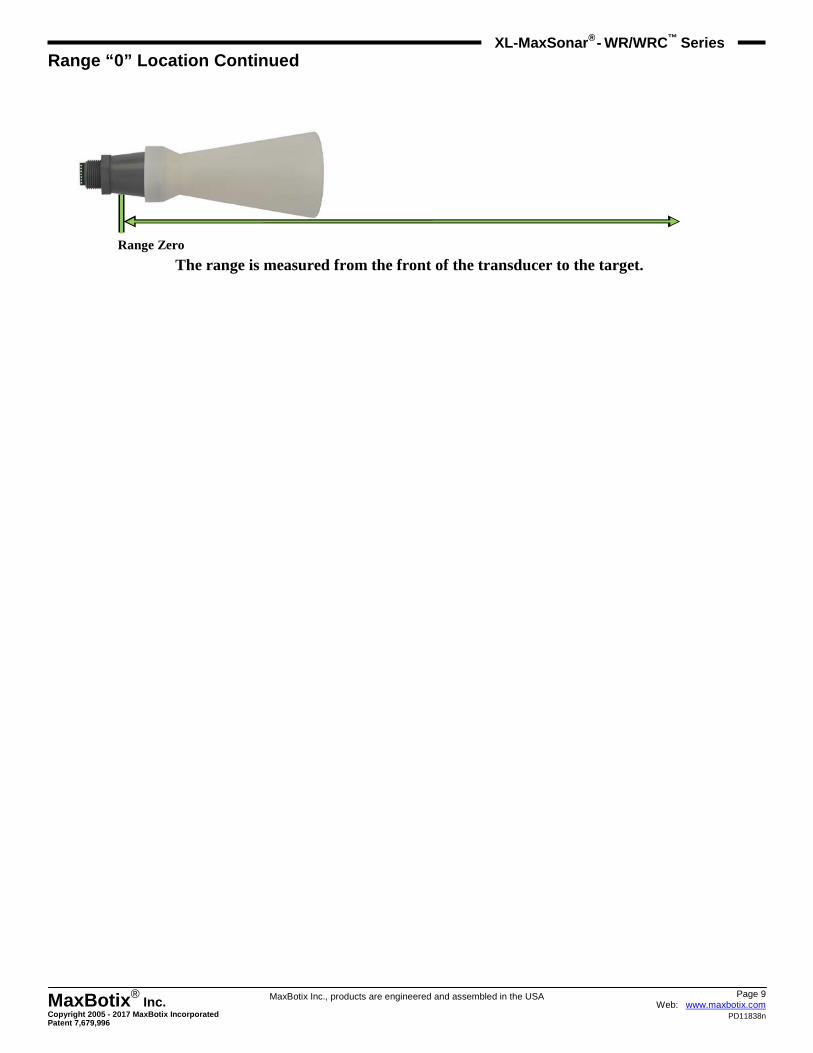
Range “0” Location Continued
The range is measured from the front of the transducer to the target. Range Zero
Page 10 Web: www.maxbotix.com
PD11838n
MaxBotix ® Inc.
Copyright 2005 - 2017 MaxBotix Incorporated Patent 7,679,996
XL-MaxSonar ® - WR/WRC™
Series
MaxBotix Inc., products are engineered and assembled in the USA
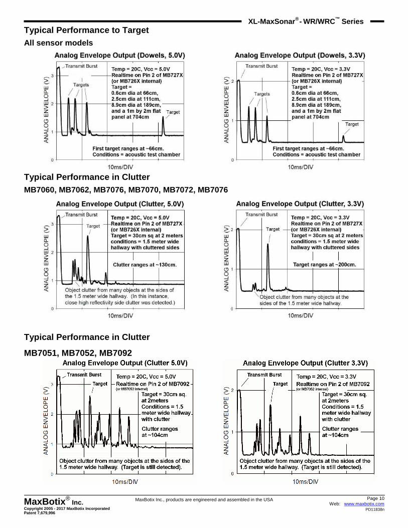
Typical Performance to Target All sensor models
Typical Performance in Clutter MB7060, MB7062, MB7076, MB7070, MB7072, MB7076
Typical Performance in Clutter
MB7051, MB7052, MB7092
Page 11 Web: www.maxbotix.com
PD11838n
MaxBotix ® Inc.
Copyright 2005 - 2017 MaxBotix Incorporated Patent 7,679,996
XL-MaxSonar ® - WR/WRC™
Series
MaxBotix Inc., products are engineered and assembled in the USA
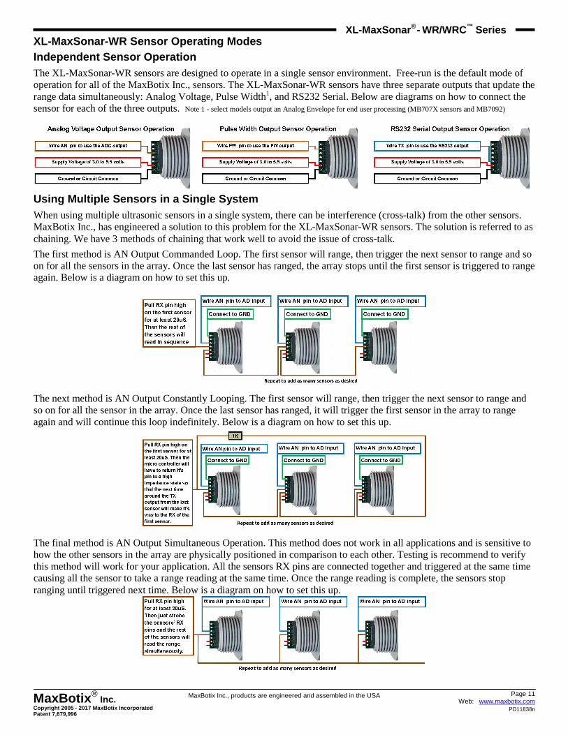
XL-MaxSonar-WR Sensor Operating Modes
Independent Sensor Operation The XL-MaxSonar-WR sensors are designed to operate in a single sensor environment. Free-run is the default mode of operation for all of the MaxBotix Inc., sensors. The XL-MaxSonar-WR sensors have three separate outputs that update the range data simultaneously: Analog Voltage, Pulse Width1, and RS232 Serial. Below are diagrams on how to connect the sensor for each of the three outputs. Note 1 - select models output an Analog Envelope for end user processing (MB707X sensors and MB7092)
Using Multiple Sensors in a Single System When using multiple ultrasonic sensors in a single system, there can be interference (cross-talk) from the other sensors. MaxBotix Inc., has engineered a solution to this problem for the XL-MaxSonar-WR sensors. The solution is referred to as chaining. We have 3 methods of chaining that work well to avoid the issue of cross-talk.
The first method is AN Output Commanded Loop. The first sensor will range, then trigger the next sensor to range and so on for all the sensors in the array. Once the last sensor has ranged, the array stops until the first sensor is triggered to range again. Below is a diagram on how to set this up.
The next method is AN Output Constantly Looping. The first sensor will range, then trigger the next sensor to range and so on for all the sensor in the array. Once the last sensor has ranged, it will trigger the first sensor in the array to range again and will continue this loop indefinitely. Below is a diagram on how to set this up.
The final method is AN Output Simultaneous Operation. This method does not work in all applications and is sensitive to how the other sensors in the array are physically positioned in comparison to each other. Testing is recommend to verify this method will work for your application. All the sensors RX pins are connected together and triggered at the same time causing all the sensor to take a range reading at the same time. Once the range reading is complete, the sensors stop ranging until triggered next time. Below is a diagram on how to set this up.
Page 12 Web: www.maxbotix.com
PD11838n
MaxBotix ® Inc.
Copyright 2005 - 2017 MaxBotix Incorporated Patent 7,679,996
XL-MaxSonar ® - WR/WRC™
Series
MaxBotix Inc., products are engineered and assembled in the USA
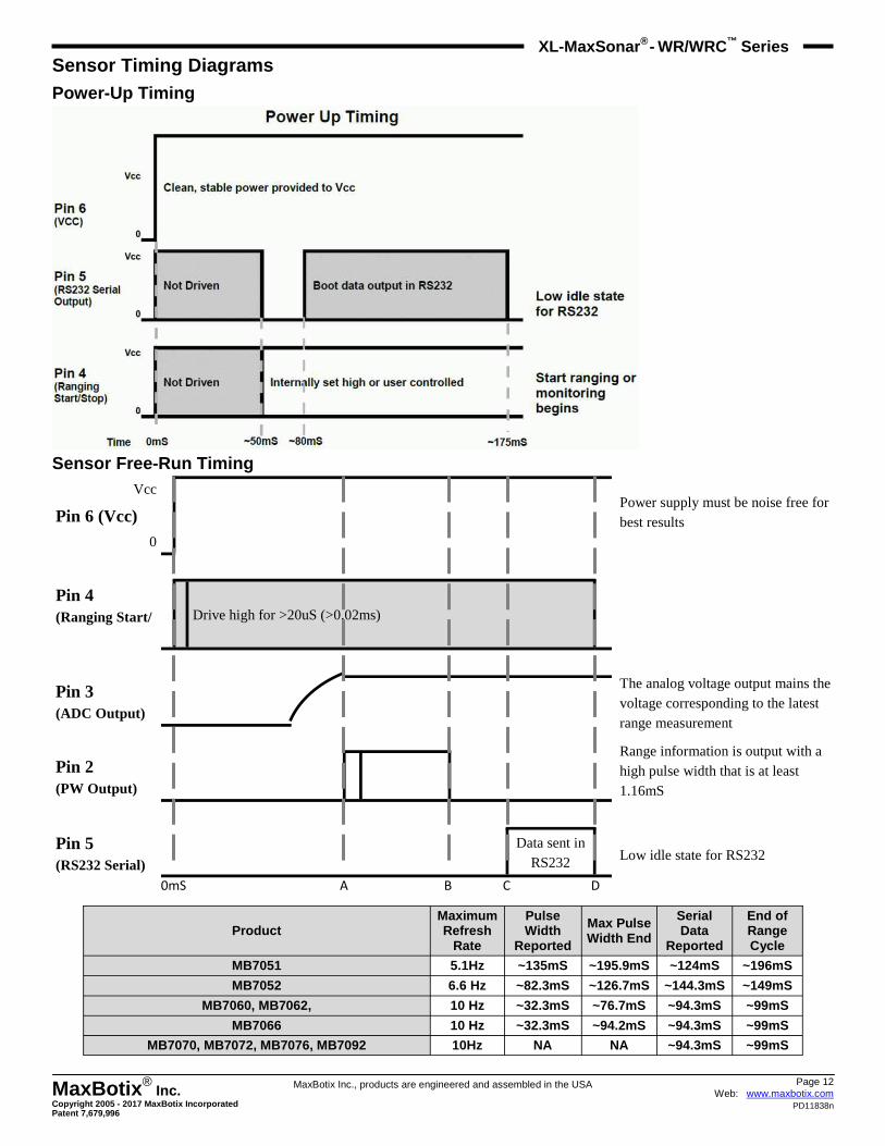
Sensor Timing Diagrams Power-Up Timing
Sensor Free-Run Timing
Vcc
Pin 6 (Vcc) 0
Pin 4 (Ranging Start/
Drive high for >20uS (>0.02ms)
Pin 3 (ADC Output)
Pin 2 (PW Output)
Pin 5 (RS232 Serial)
Data sent in RS232
0mS A B C D
Power supply must be noise free for best results
The analog voltage output mains the voltage corresponding to the latest range measurement
Range information is output with a high pulse width that is at least 1.16mS
Low idle state for RS232
Product Maximum Refresh
Rate
Pulse Width
Reported
Max Pulse Width End
Serial Data
Reported
End of Range Cycle
MB7052 6.6 Hz ~82.3mS ~126.7mS ~144.3mS ~149mS
MB7060, MB7062, 10 Hz ~32.3mS ~76.7mS ~94.3mS ~99mS
MB7066 10 Hz ~32.3mS ~94.2mS ~94.3mS ~99mS
MB7070, MB7072, MB7076, MB7092 10Hz NA NA ~94.3mS ~99mS
MB7051 5.1Hz ~135mS ~195.9mS ~124mS ~196mS
Page 13 Web: www.maxbotix.com
PD11838n
MaxBotix ® Inc.
Copyright 2005 - 2017 MaxBotix Incorporated Patent 7,679,996
XL-MaxSonar ® - WR/WRC™
Series
MaxBotix Inc., products are engineered and assembled in the USA
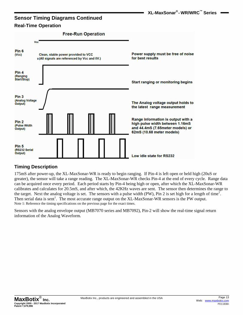
Sensor Timing Diagrams Continued Real-Time Operation
Timing Description 175mS after power-up, the XL-MaxSonar-WR is ready to begin ranging. If Pin-4 is left open or held high (20uS or greater), the sensor will take a range reading. The XL-MaxSonar-WR checks Pin-4 at the end of every cycle. Range data can be acquired once every period. Each period starts by Pin-4 being high or open, after which the XL-MaxSonar-WR calibrates and calculates for 20.5mS, and after which, the 42KHz waves are sent. The sensor then determines the range to the target. Next the analog voltage is set. The sensors with a pulse width (PW), Pin 2 is set high for a length of time1. Then serial data is sent1. The most accurate range output on the XL-MaxSonar-WR sensors is the PW output. Note 1: Reference the timing specifications on the previous page for the exact times.
Sensors with the analog envelope output (MB7070 series and MB7092), Pin-2 will show the real-time signal return information of the Analog Waveform.
Page 14 Web: www.maxbotix.com
PD11838n
MaxBotix ® Inc.
Copyright 2005 - 2017 MaxBotix Incorporated Patent 7,679,996
XL-MaxSonar ® - WR/WRC™
Series
MaxBotix Inc., products are engineered and assembled in the USA
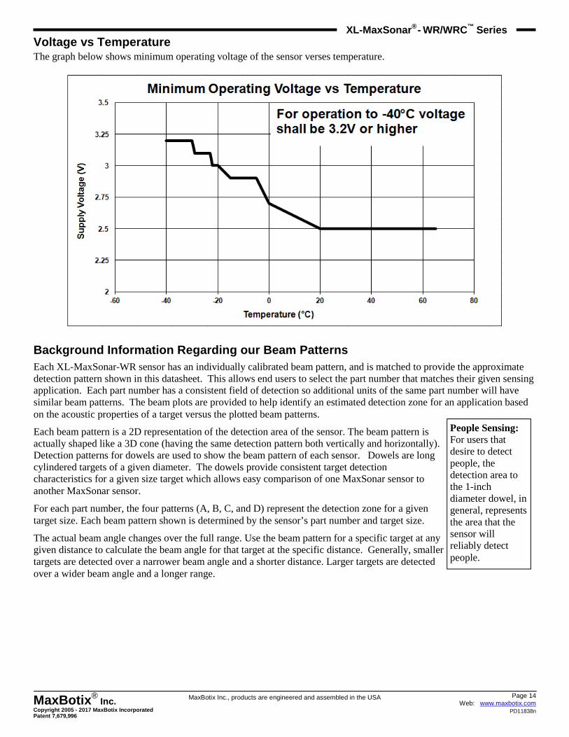
Voltage vs Temperature The graph below shows minimum operating voltage of the sensor verses temperature.
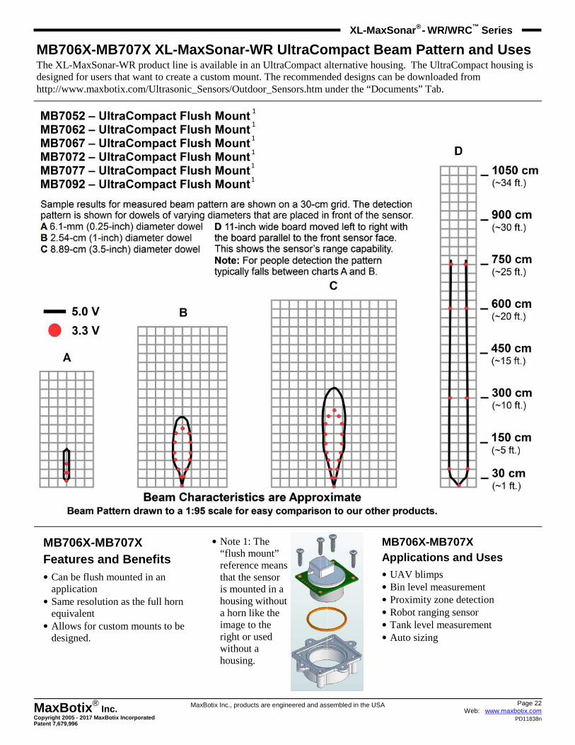
Background Information Regarding our Beam Patterns Each XL-MaxSonar-WR sensor has an individually calibrated beam pattern, and is matched to provide the approximate detection pattern shown in this datasheet. This allows end users to select the part number that matches their given sensing application. Each part number has a consistent field of detection so additional units of the same part number will have similar beam patterns. The beam plots are provided to help identify an estimated detection zone for an application based on the acoustic properties of a target versus the plotted beam patterns.
Each beam pattern is a 2D representation of the detection area of the sensor. The beam pattern is actually shaped like a 3D cone (having the same detection pattern both vertically and horizontally). Detection patterns for dowels are used to show the beam pattern of each sensor. Dowels are long cylindered targets of a given diameter. The dowels provide consistent target detection characteristics for a given size target which allows easy comparison of one MaxSonar sensor to another MaxSonar sensor.
For each part number, the four patterns (A, B, C, and D) represent the detection zone for a given target size. Each beam pattern shown is determined by the sensor’s part number and target size.
The actual beam angle changes over the full range. Use the beam pattern for a specific target at any given distance to calculate the beam angle for that target at the specific distance. Generally, smaller targets are detected over a narrower beam angle and a shorter distance. Larger targets are detected over a wider beam angle and a longer range.
People Sensing: For users that desire to detect people, the detection area to the 1-inch diameter dowel, in general, represents the area that the sensor will reliably detect people.
Page 15 Web: www.maxbotix.com
PD11838n
MaxBotix ® Inc.
Copyright 2005 - 2017 MaxBotix Incorporated Patent 7,679,996
XL-MaxSonar ® - WR/WRC™
Series
MaxBotix Inc., products are engineered and assembled in the USA
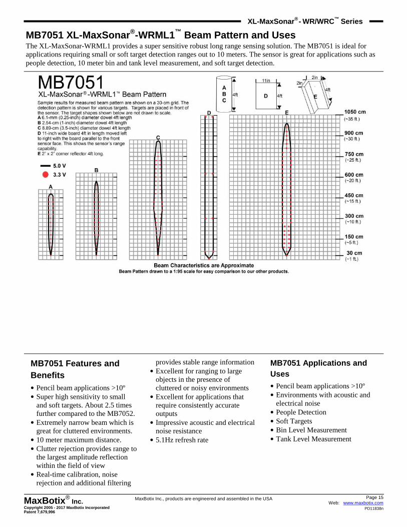
MB7051 XL-MaxSonar ®-WRML1™ Beam Pattern and Uses The XL-MaxSonar-WRML1 provides a super sensitive robust long range sensing solution. The MB7051 is ideal for applications requiring small or soft target detection ranges out to 10 meters. The sensor is great for applications such as people detection, 10 meter bin and tank level measurement, and soft target detection.
MB7051 Features and Benefits • Pencil beam applications >10º • Super high sensitivity to small
and soft targets. About 2.5 times further compared to the MB7052. • Extremely narrow beam which is
great for cluttered environments. • 10 meter maximum distance. • Clutter rejection provides range to
the largest amplitude reflection within the field of view • Real-time calibration, noise
rejection and additional filtering
provides stable range information • Excellent for ranging to large
objects in the presence of cluttered or noisy environments • Excellent for applications that
require consistently accurate outputs • Impressive acoustic and electrical
noise resistance • 5.1Hz refresh rate
MB7051 Applications and Uses • Pencil beam applications >10º • Environments with acoustic and
electrical noise • People Detection • Soft Targets • Bin Level Measurement • Tank Level Measurement
Page 16 Web: www.maxbotix.com
PD11838n
MaxBotix ® Inc.
Copyright 2005 - 2017 MaxBotix Incorporated Patent 7,679,996
XL-MaxSonar ® - WR/WRC™
Series
MaxBotix Inc., products are engineered and assembled in the USA
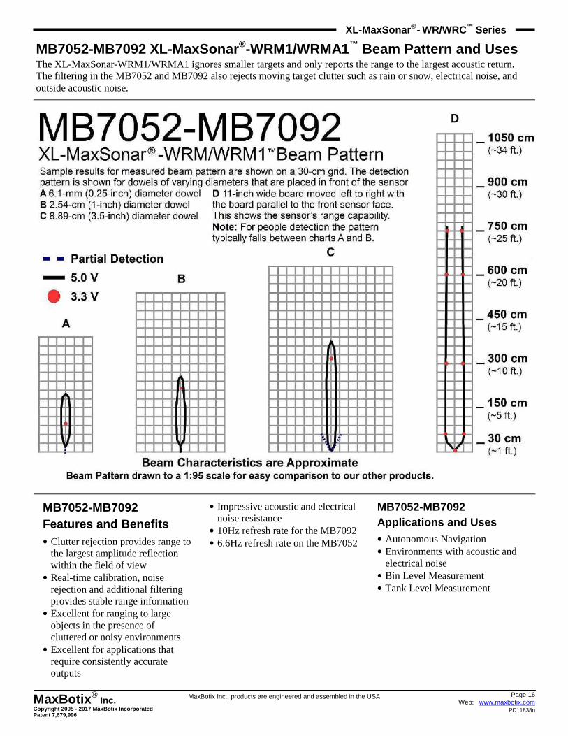
MB7052-MB7092 XL-MaxSonar ®-WRM1/WRMA1™ Beam Pattern and Uses The XL-MaxSonar-WRM1/WRMA1 ignores smaller targets and only reports the range to the largest acoustic return. The filtering in the MB7052 and MB7092 also rejects moving target clutter such as rain or snow, electrical noise, and outside acoustic noise.
MB7052-MB7092 Features and Benefits • Clutter rejection provides range to
the largest amplitude reflection within the field of view • Real-time calibration, noise
rejection and additional filtering provides stable range information • Excellent for ranging to large
objects in the presence of cluttered or noisy environments • Excellent for applications that
require consistently accurate outputs
• Impressive acoustic and electrical noise resistance • 10Hz refresh rate for the MB7092 • 6.6Hz refresh rate on the MB7052
MB7052-MB7092 Applications and Uses • Autonomous Navigation • Environments with acoustic and
electrical noise • Bin Level Measurement • Tank Level Measurement
Page 17 Web: www.maxbotix.com
PD11838n
MaxBotix ® Inc.
Copyright 2005 - 2017 MaxBotix Incorporated Patent 7,679,996
XL-MaxSonar ® - WR/WRC™
Series
MaxBotix Inc., products are engineered and assembled in the USA
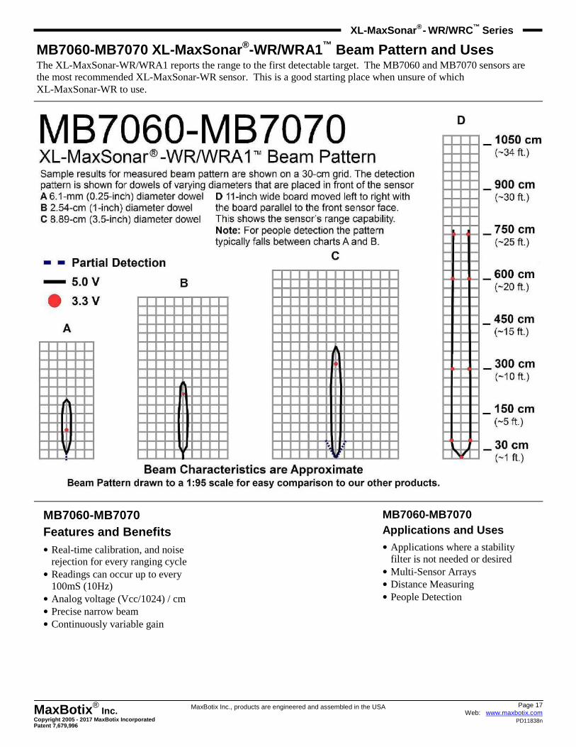
MB7060-MB7070 XL-MaxSonar ®-WR/WRA1™ Beam Pattern and Uses The XL-MaxSonar-WR/WRA1 reports the range to the first detectable target. The MB7060 and MB7070 sensors are the most recommended XL-MaxSonar-WR sensor. This is a good starting place when unsure of which XL-MaxSonar-WR to use.
MB7060-MB7070 Features and Benefits • Real-time calibration, and noise
rejection for every ranging cycle • Readings can occur up to every
100mS (10Hz) • Analog voltage (Vcc/1024) / cm • Precise narrow beam • Continuously variable gain
MB7060-MB7070 Applications and Uses • Applications where a stability
filter is not needed or desired • Multi-Sensor Arrays • Distance Measuring • People Detection
Page 18 Web: www.maxbotix.com
PD11838n
MaxBotix ® Inc.
Copyright 2005 - 2017 MaxBotix Incorporated Patent 7,679,996
XL-MaxSonar ® - WR/WRC™
Series
MaxBotix Inc., products are engineered and assembled in the USA
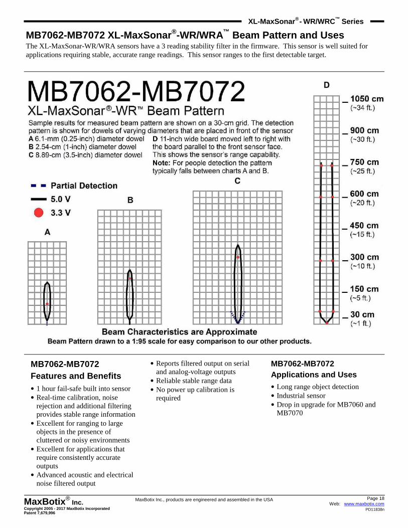
MB7062-MB7072 XL-MaxSonar ®-WR/WRA™ Beam Pattern and Uses The XL-MaxSonar-WR/WRA sensors have a 3 reading stability filter in the firmware. This sensor is well suited for applications requiring stable, accurate range readings. This sensor ranges to the first detectable target.
MB7062-MB7072 Features and Benefits • 1 hour fail-safe built into sensor • Real-time calibration, noise
rejection and additional filtering provides stable range information • Excellent for ranging to large
objects in the presence of cluttered or noisy environments • Excellent for applications that
require consistently accurate outputs • Advanced acoustic and electrical
noise filtered output
• Reports filtered output on serial and analog-voltage outputs • Reliable stable range data • No power up calibration is
required
MB7062-MB7072 Applications and Uses • Long range object detection • Industrial sensor • Drop in upgrade for MB7060 and
MB7070
Page 19 Web: www.maxbotix.com
PD11838n
MaxBotix ® Inc.
Copyright 2005 - 2017 MaxBotix Incorporated Patent 7,679,996
XL-MaxSonar ® - WR/WRC™
Series
MaxBotix Inc., products are engineered and assembled in the USA
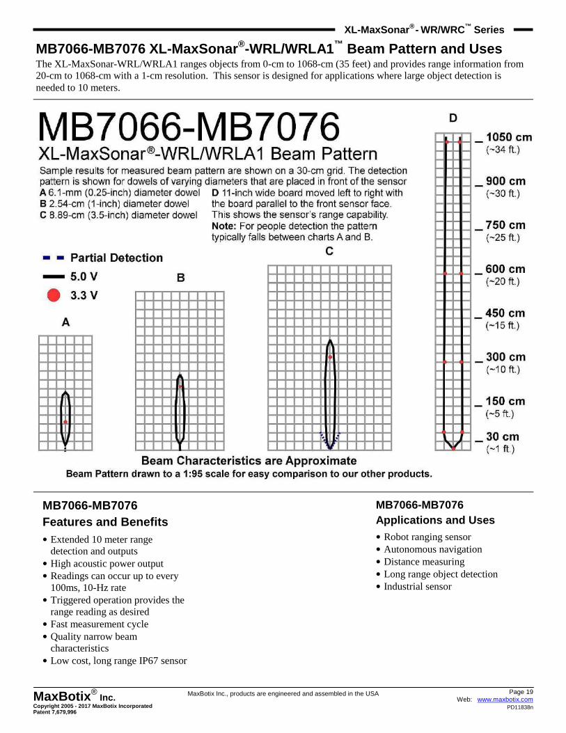
MB7066-MB7076 XL-MaxSonar ®-WRL/WRLA1 ™ Beam Pattern and Uses The XL-MaxSonar-WRL/WRLA1 ranges objects from 0-cm to 1068-cm (35 feet) and provides range information from 20-cm to 1068-cm with a 1-cm resolution. This sensor is designed for applications where large object detection is needed to 10 meters.
MB7066-MB7076 Features and Benefits • Extended 10 meter range
detection and outputs • High acoustic power output • Readings can occur up to every
100ms, 10-Hz rate • Triggered operation provides the
range reading as desired • Fast measurement cycle • Quality narrow beam
characteristics • Low cost, long range IP67 sensor
MB7066-MB7076 Applications and Uses • Robot ranging sensor • Autonomous navigation • Distance measuring • Long range object detection • Industrial sensor
Page 20 Web: www.maxbotix.com
PD11838n
MaxBotix ® Inc.
Copyright 2005 - 2017 MaxBotix Incorporated Patent 7,679,996
XL-MaxSonar ® - WR/WRC™
Series
MaxBotix Inc., products are engineered and assembled in the USA
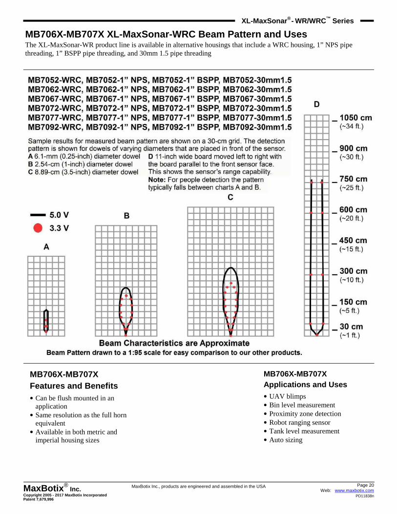
MB706X-MB707X XL-MaxSonar-WRC Beam Pattern and Uses The XL-MaxSonar-WR product line is available in alternative housings that include a WRC housing, 1” NPS pipe threading, 1” BSPP pipe threading, and 30mm 1.5 pipe threading
MB706X-MB707X Features and Benefits • Can be flush mounted in an
application • Same resolution as the full horn
equivalent • Available in both metric and
imperial housing sizes
MB706X-MB707X Applications and Uses • UAV blimps • Bin level measurement • Proximity zone detection • Robot ranging sensor • Tank level measurement • Auto sizing
Page 21 Web: www.maxbotix.com
PD11838n
MaxBotix ® Inc.
Copyright 2005 - 2017 MaxBotix Incorporated Patent 7,679,996
XL-MaxSonar ® - WR/WRC™
Series
MaxBotix Inc., products are engineered and assembled in the USA
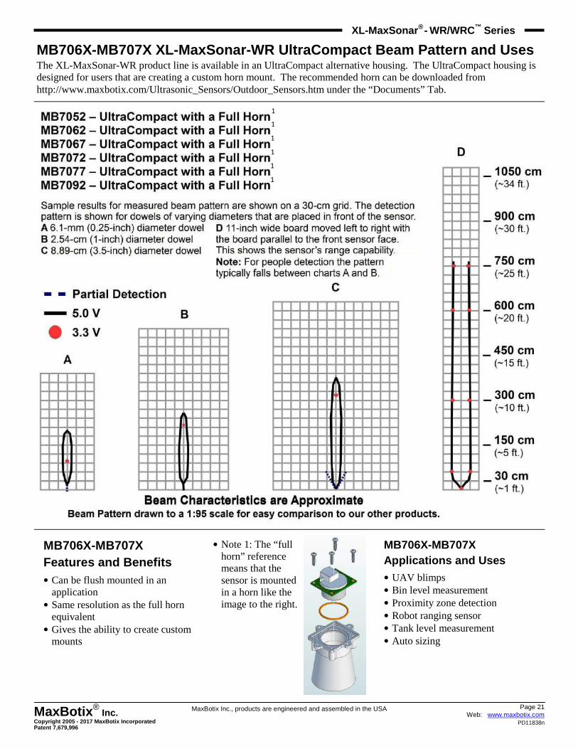
MB706X-MB707X XL-MaxSonar-WR UltraCompact Beam Patt ern and Uses The XL-MaxSonar-WR product line is available in an UltraCompact alternative housing. The UltraCompact housing is designed for users that are creating a custom horn mount. The recommended horn can be downloaded from http://www.maxbotix.com/Ultrasonic_Sensors/Outdoor_Sensors.htm under the “Documents” Tab.
MB706X-MB707X Features and Benefits • Can be flush mounted in an
application • Same resolution as the full horn
equivalent • Gives the ability to create custom
mounts
• Note 1: The “full horn” reference means that the sensor is mounted in a horn like the image to the right.
MB706X-MB707X Applications and Uses • UAV blimps • Bin level measurement • Proximity zone detection • Robot ranging sensor • Tank level measurement • Auto sizing
1
1
1
1
1
1
Page 22 Web: www.maxbotix.com
PD11838n
MaxBotix ® Inc.
Copyright 2005 - 2017 MaxBotix Incorporated Patent 7,679,996
XL-MaxSonar ® - WR/WRC™
Series
MaxBotix Inc., products are engineered and assembled in the USA
MB706X-MB707X XL-MaxSonar-WR UltraCompact Beam Patt ern and Uses The XL-MaxSonar-WR product line is available in an UltraCompact alternative housing. The UltraCompact housing is designed for users that want to create a custom mount. The recommended designs can be downloaded from http://www.maxbotix.com/Ultrasonic_Sensors/Outdoor_Sensors.htm under the “Documents” Tab.
MB706X-MB707X Features and Benefits • Can be flush mounted in an
application • Same resolution as the full horn
equivalent • Allows for custom mounts to be
designed.
• Note 1: The “flush mount” reference means that the sensor is mounted in a housing without a horn like the image to the right or used without a housing.
MB706X-MB707X Applications and Uses • UAV blimps • Bin level measurement • Proximity zone detection • Robot ranging sensor • Tank level measurement • Auto sizing
1
1
1
1
1
1
Page 23 Web: www.maxbotix.com
PD11838n
MaxBotix ® Inc.
Copyright 2005 - 2017 MaxBotix Incorporated Patent 7,679,996
XL-MaxSonar ® - WR/WRC™
Series
MaxBotix Inc., products are engineered and assembled in the USA
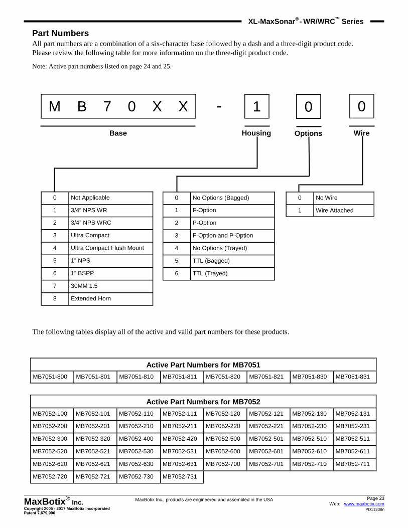
Part Numbers All part numbers are a combination of a six-character base followed by a dash and a three-digit product code. Please review the following table for more information on the three-digit product code.
Note: Active part numbers listed on page 24 and 25.
M B 7 0 X X - 1 0 0
Base Housing Options Wire
0 Not Applicable
1 3/4” NPS WR
2 3/4” NPS WRC
3 Ultra Compact
4 Ultra Compact Flush Mount
5 1” NPS
6 1” BSPP
7 30MM 1.5
8 Extended Horn
0 No Options (Bagged)
1 F-Option
2 P-Option
3 F-Option and P-Option
4 No Options (Trayed)
5 TTL (Bagged)
6 TTL (Trayed)
0 No Wire
1 Wire Attached
The following tables display all of the active and valid part numbers for these products.
Active Part Numbers for MB7051
MB7051-800 MB7051-801 MB7051-810 MB7051-811 MB7051-820 MB7051-821 MB7051-830 MB7051-831
Active Part Numbers for MB7052
MB7052-100 MB7052-101 MB7052-110 MB7052-111 MB7052-120 MB7052-121 MB7052-130 MB7052-131
MB7052-200 MB7052-201 MB7052-210 MB7052-211 MB7052-220 MB7052-221 MB7052-230 MB7052-231
MB7052-300 MB7052-320 MB7052-400 MB7052-420 MB7052-500 MB7052-501 MB7052-510 MB7052-511
MB7052-520 MB7052-521 MB7052-530 MB7052-531 MB7052-600 MB7052-601 MB7052-610 MB7052-611
MB7052-620 MB7052-621 MB7052-630 MB7052-631 MB7052-700 MB7052-701 MB7052-710 MB7052-711
MB7052-720 MB7052-721 MB7052-730 MB7052-731
Page 24 Web: www.maxbotix.com
PD11838n
MaxBotix ® Inc.
Copyright 2005 - 2017 MaxBotix Incorporated Patent 7,679,996
XL-MaxSonar ® - WR/WRC™
Series
MaxBotix Inc., products are engineered and assembled in the USA
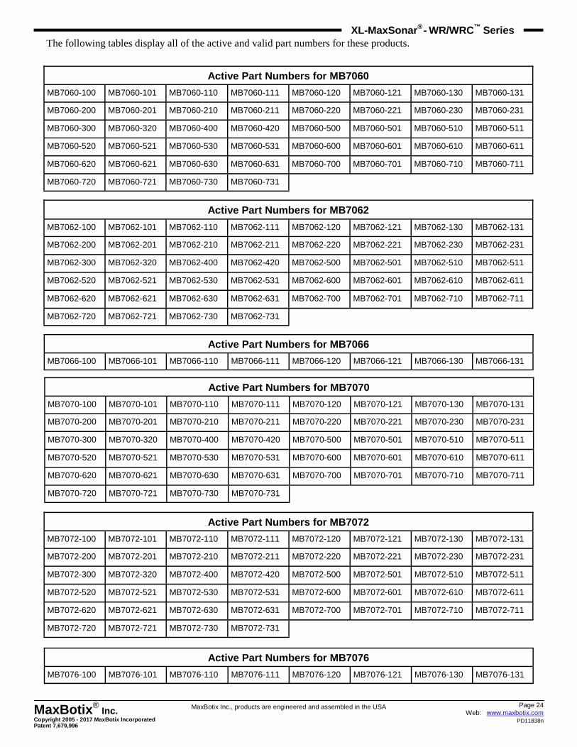
The following tables display all of the active and valid part numbers for these products.
Active Part Numbers for MB7060
MB7060-100 MB7060-101 MB7060-110 MB7060-111 MB7060-120 MB7060-121 MB7060-130 MB7060-131
MB7060-200 MB7060-201 MB7060-210 MB7060-211 MB7060-220 MB7060-221 MB7060-230 MB7060-231
MB7060-300 MB7060-320 MB7060-400 MB7060-420 MB7060-500 MB7060-501 MB7060-510 MB7060-511
MB7060-520 MB7060-521 MB7060-530 MB7060-531 MB7060-600 MB7060-601 MB7060-610 MB7060-611
MB7060-620 MB7060-621 MB7060-630 MB7060-631 MB7060-700 MB7060-701 MB7060-710 MB7060-711
MB7060-720 MB7060-721 MB7060-730 MB7060-731
Active Part Numbers for MB7062
MB7062-100 MB7062-101 MB7062-110 MB7062-111 MB7062-120 MB7062-121 MB7062-130 MB7062-131
MB7062-200 MB7062-201 MB7062-210 MB7062-211 MB7062-220 MB7062-221 MB7062-230 MB7062-231
MB7062-300 MB7062-320 MB7062-400 MB7062-420 MB7062-500 MB7062-501 MB7062-510 MB7062-511
MB7062-520 MB7062-521 MB7062-530 MB7062-531 MB7062-600 MB7062-601 MB7062-610 MB7062-611
MB7062-620 MB7062-621 MB7062-630 MB7062-631 MB7062-700 MB7062-701 MB7062-710 MB7062-711
MB7062-720 MB7062-721 MB7062-730 MB7062-731
Active Part Numbers for MB7066
MB7066-100 MB7066-101 MB7066-110 MB7066-111 MB7066-120 MB7066-121 MB7066-130 MB7066-131
Active Part Numbers for MB7070
MB7070-100 MB7070-101 MB7070-110 MB7070-111 MB7070-120 MB7070-121 MB7070-130 MB7070-131
MB7070-200 MB7070-201 MB7070-210 MB7070-211 MB7070-220 MB7070-221 MB7070-230 MB7070-231
MB7070-300 MB7070-320 MB7070-400 MB7070-420 MB7070-500 MB7070-501 MB7070-510 MB7070-511
MB7070-520 MB7070-521 MB7070-530 MB7070-531 MB7070-600 MB7070-601 MB7070-610 MB7070-611
MB7070-620 MB7070-621 MB7070-630 MB7070-631 MB7070-700 MB7070-701 MB7070-710 MB7070-711
MB7070-720 MB7070-721 MB7070-730 MB7070-731
Active Part Numbers for MB7072
MB7072-100 MB7072-101 MB7072-110 MB7072-111 MB7072-120 MB7072-121 MB7072-130 MB7072-131
MB7072-200 MB7072-201 MB7072-210 MB7072-211 MB7072-220 MB7072-221 MB7072-230 MB7072-231
MB7072-300 MB7072-320 MB7072-400 MB7072-420 MB7072-500 MB7072-501 MB7072-510 MB7072-511
MB7072-520 MB7072-521 MB7072-530 MB7072-531 MB7072-600 MB7072-601 MB7072-610 MB7072-611
MB7072-620 MB7072-621 MB7072-630 MB7072-631 MB7072-700 MB7072-701 MB7072-710 MB7072-711
MB7072-720 MB7072-721 MB7072-730 MB7072-731
Active Part Numbers for MB7076
MB7076-100 MB7076-101 MB7076-110 MB7076-111 MB7076-120 MB7076-121 MB7076-130 MB7076-131
Page 25 Web: www.maxbotix.com
PD11838n
MaxBotix ® Inc.
Copyright 2005 - 2017 MaxBotix Incorporated Patent 7,679,996
XL-MaxSonar ® - WR/WRC™
Series
MaxBotix Inc., products are engineered and assembled in the USA
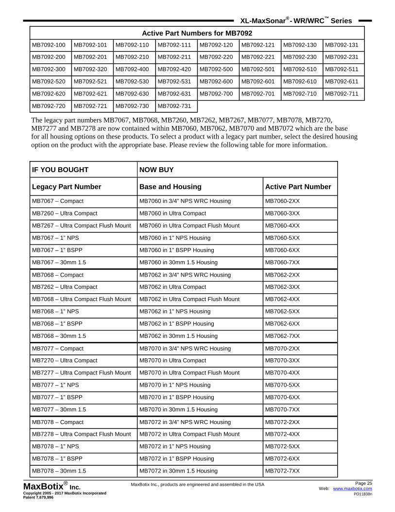
Active Part Numbers for MB7092
MB7092-100 MB7092-101 MB7092-110 MB7092-111 MB7092-120 MB7092-121 MB7092-130 MB7092-131
MB7092-200 MB7092-201 MB7092-210 MB7092-211 MB7092-220 MB7092-221 MB7092-230 MB7092-231
MB7092-300 MB7092-320 MB7092-400 MB7092-420 MB7092-500 MB7092-501 MB7092-510 MB7092-511
MB7092-520 MB7092-521 MB7092-530 MB7092-531 MB7092-600 MB7092-601 MB7092-610 MB7092-611
MB7092-620 MB7092-621 MB7092-630 MB7092-631 MB7092-700 MB7092-701 MB7092-710 MB7092-711
MB7092-720 MB7092-721 MB7092-730 MB7092-731
The legacy part numbers MB7067, MB7068, MB7260, MB7262, MB7267, MB7077, MB7078, MB7270, MB7277 and MB7278 are now contained within MB7060, MB7062, MB7070 and MB7072 which are the base for all housing options on these products. To select a product with a legacy part number, select the desired housing option on the product with the appropriate base. Please review the following table for more information.
IF YOU BOUGHT NOW BUY
Legacy Part Number Base and Housing Active Part Num ber
MB7067 – Compact MB7060 in 3/4” NPS WRC Housing MB7060-2XX
MB7260 – Ultra Compact MB7060 in Ultra Compact MB7060-3XX
MB7267 – Ultra Compact Flush Mount MB7060 in Ultra Compact Flush Mount MB7060-4XX
MB7067 – 1” NPS MB7060 in 1” NPS Housing MB7060-5XX
MB7067 – 1” BSPP MB7060 in 1” BSPP Housing MB7060-6XX
MB7067 – 30mm 1.5 MB7060 in 30mm 1.5 Housing MB7060-7XX
MB7068 – Compact MB7062 in 3/4” NPS WRC Housing MB7062-2XX
MB7262 – Ultra Compact MB7062 in Ultra Compact MB7062-3XX
MB7068 – Ultra Compact Flush Mount MB7062 in Ultra Compact Flush Mount MB7062-4XX
MB7068 – 1” NPS MB7062 in 1” NPS Housing MB7062-5XX
MB7068 – 1” BSPP MB7062 in 1” BSPP Housing MB7062-6XX
MB7068 – 30mm 1.5 MB7062 in 30mm 1.5 Housing MB7062-7XX
MB7077 – Compact MB7070 in 3/4” NPS WRC Housing MB7070-2XX
MB7270 – Ultra Compact MB7070 in Ultra Compact MB7070-3XX
MB7277 – Ultra Compact Flush Mount MB7070 in Ultra Compact Flush Mount MB7070-4XX
MB7077 – 1” NPS MB7070 in 1” NPS Housing MB7070-5XX
MB7077 – 1” BSPP MB7070 in 1” BSPP Housing MB7070-6XX
MB7077 – 30mm 1.5 MB7070 in 30mm 1.5 Housing MB7070-7XX
MB7078 – Compact MB7072 in 3/4” NPS WRC Housing MB7072-2XX
MB7278 – Ultra Compact Flush Mount MB7072 in Ultra Compact Flush Mount MB7072-4XX
MB7078 – 1” NPS MB7072 in 1” NPS Housing MB7072-5XX
MB7078 – 1” BSPP MB7072 in 1” BSPP Housing MB7072-6XX
MB7078 – 30mm 1.5 MB7072 in 30mm 1.5 Housing MB7072-7XX