Embed Size (px)
Citation preview
Issue Date: Reference No:
28 May 2013T1118/0022
Signatory: G Stonesfor Chief Executive
National Measurement Office | Stanton Avenue | Teddington | TW11 0JZ | United KingdomTel +44 (0)20 8943 7272 | Fax +44 (0)20 8943 7270 | Web
NMO is an Executive Agency of the Department for Business Innovation & Skills
(1958/77, 2437/51, 2461/43, 2780/26)
SUPPLEMENT TO CERTIFICATE
(*) Refers to the dispenser only, the self service device described in these certificates is not part of this approval.(**) This certificate replaces 2780/25 issued to HTEC Ltd as part of V Series Certificate V002
In accordance with the provisions of section 12 of the Weights and Measures Act 1985, the Secretary of State for Business, Innovation and Skills hereby certifies as suitable for use for trade a pattern of a liquid flowmeter, as described in the descriptivethis Certificate, and having the following characteristics:
DISPENSER:
COMBINED KIOSK CONTROL UNITAND POINT OF SALE TERMINAL:
CARD READER / OUTDOOR PAYMENT TERMINAL:
Note: This certificate relates to the suitability of the respect of its metrological characteristics. It does not constitute or imply any guarantee as to the safety of the equipment in use for trade or otherwise.
Submitted by:
20138/0022
G StonesChief Executive
0135
National Measurement Office | Stanton Avenue | Teddington | TW11 0JZ | United KingdomTel +44 (0)20 8943 7272 | Fax +44 (0)20 8943 7270 | Web www.bis.gov.uk/nmo
NMO is an Executive Agency of the Department for Business Innovation & Skills
SUPPLEMENT TO CERTIFICATE
Series S038 Revision 2
Certification No.
Supplement No.
1958/53* 77
2437/38* 51
2461/26* 43
2780 26**
(*) Refers to the dispenser only, the self service device described in these certificates is not part of this
(**) This certificate replaces 2780/25 issued to HTEC Ltd as part of V Series Certificate V002
In accordance with the provisions of section 12 of the Weights and Measures Act 1985, the Secretary of State for Business, Innovation and Skills hereby certifies as suitable for use for trade a pattern of a liquid flowmeter, as described in the descriptivethis Certificate, and having the following characteristics:-
Dispensers described in certification numbers: 1958, 2437, 2461, 2780
COMBINED KIOSK CONTROL
AND POINT OF SALE TERMINAL:
HTEC HydraPOS, combined kiosk control unit point of sale equipment as described in the descriptive annex.
CARD READER / OUTDOOR HTEC Sirius CRIND card reader or described in the descriptive annex.
Note: This certificate relates to the suitability of the equipment for use for trade only in respect of its metrological characteristics. It does not constitute or imply any guarantee as to the safety of the equipment in use for trade or otherwise.
Submitted by:HTEC LtdGeorge Curl WaySouthamptonSO18 2RXUnited Kingdom
III(5)a
(*) Refers to the dispenser only, the self service device described in these certificates is not part of this
(**) This certificate replaces 2780/25 issued to HTEC Ltd as part of V Series Certificate V002
In accordance with the provisions of section 12 of the Weights and Measures Act 1985, the Secretary of State for Business, Innovation and Skills hereby certifies as suitable for use for trade a pattern of a liquid flowmeter, as described in the descriptive annex to
Dispensers described in certification numbers:
HTEC HydraPOS, combined kiosk control unit and point of sale equipment as described in the
or HydraOPT II as described in the descriptive annex.
equipment for use for trade only in respect of its metrological characteristics. It does not constitute or imply any guarantee
2
CONTENTS
1 INTRODUCTION
2 CONSTRUCTION2.1 General2.2 IBM SurePOS 5002.3 Processor unit2.4 Epson IR310 M156A2.5 Toshiba TEC 56002.6 Uninterruptible power supply (UPS)2.7 Opto–isolator unit2.8 Outdoor payment terminal (OPT)
3 OPERATION3.1 Controls and features3.2 Sequence of operations3.3 Interlocks and security features3.4 Software overview3.5 Software issue and security features3.6 Software Version and Metrology Code History
4 AUTHORISED ALTERNATIVES
5 RECOMMENDED TESTS
6 HTEC SIRIUS CRIND CARD READER
7 CERTIFICATE HISTORY
ILLUSTRATIONS
Figure 1 IBM SurePOS 500 processor unitFigure 2 IBM / HydraPOS systemFigure 3 IBM SurePOS integrated CDUFigure 4 PC used with IBM /HydraPOS systemFigure 5 Rear view of PC as used with IBM /HydraPOS systemFigure 6 Epson IR 310 PC POSFigure 7 Epson / HydraPOS systemFigure 8 Toshiba TEC 5600 point of saleFigure 9 Toshiba TEC / HydraPOS systemFigure 10 Opto-isolator unit (part number 950-00178-100)Figure 11 HydraPOS with HTEC CRIND OPTFigure 12 RS232 / LON interface unit (part number 950-00170-100)Figure 13 Typical kiosk receiptFigure 14 HTEC pump interface, part number 950-00210-100Figure 15 HTEC pump interface 950-00210-100: rear view showing connectionsFigure 16 HTEC pump interface 950-00210-100, functional diagramFigure 17 Diagram showing typical set-upFigure 18 HTEC Hydra SC400 site controller: part number 950-00214-100: rear viewFigure 19 HTEC Hydra SC400 site controller: part number 950-00214-100: front view
showing fault condition changeover switchesFigure 20 HTEC Hydra SC400 site controller: typical set-up
3
Figure 21 View of TEC ST-6501-C54C1-QM showing rear connections and display unit with swipe card
Figure 22 Front and rear views of TEC ST-60-C showing card-swipe and CDUFigure 23 Front and rear views of Digipos ‘Millennium’ showing external power supply
and rear connectionsFigure 24 Sharp UP5900Figure 25 Sharp UP5900 – rear view showing integrated CDUFigure 26 Toshiba TEC ST-6501-C74C2-QMFigure 27 Epson MR800 POS systemFigure 28 Epson MR800 POS unit – rear panel – cover removed
note: pump control connection (not shown) goes to USB portFigure 29 Toshiba TEC ST-70 POS unit showing kiosk display and customer displayFigure 30 Toshiba TEC ST-70 POS unit (front panel – cover removed)
note: Pump control connection goes to USB portFigure 31 Toshiba TEC receipt printer TRST-56-S-1G-QMFigure 32 View of back panel – cover removed - showing 24 V outletFigure 33 Epson IR 700 – front viewFigure 34 Epson IR 700 – showing rear connections with protective cover removed Figure 35 Diagram showing typical USB set-upFigure 36 Toshiba ST-71 with integrated customer display unitFigure 37 Port layout of ST-71 terminalFigure 38 Toshiba ST-7000 with typical operator displayFigure 39 Port layout of ST-7000Figure 40 DigiPoS Retail Blade EPOS PCFigure 41 Front view of PH6000T System Unit showing Main system unit (top) and IO
Expansion Hub (bottom)Figure 42 Solution architecture with DOMS Controller Figure 43 DOMS PSS 5000Figure 44 Central Processing Board (CPB508) display and menu navigation keysFigure 45 General view of CRIND SIRIUS terminalFigure 46 Display screen (showing initial display)Figure 47 SIRIUS CRIND terminal functional diagramFigure 48 System interconnectionsFigure 49 Protocol converter boxFigure 50 Typical receiptFigure 51 HTEC Hydra SC400 MkII (Resiliant) site controller, part number 950-00251-
100Figure 52 HTEC Hydra SC400 MkII (side A) site controller, part number 950-00251-101Figure 53 Rear face of Toshiba TEC ST B 10Figure 54 HYDRA-U processor unitFigure 55 Block diagram: HYDRA-U set-upFigure 56 Block diagram: Typical HYDRA-U system set-upFigure 57 SiriusCRIND 2 General viewFigure 58 SiriusCRIND 2 showing controlsFigure 59 SiriusCRIND 2 typical receiptFigure 60 Dell Optiplex GX85Figure 61 HydraOPT II
4
Descriptive Annex1 INTRODUCTION
The HTEC ‘HydraPOS’ system is a combined kiosk control unit and point of sale equipment. It includes communications links via ISDN and optionally MODEM connections which allow the checking of credit/payment/fuel cards with the appropriate remote authorisation databases and collection of all transaction data by a remote head office. Fault diagnosis and corrective action may also be performed via the communications links minimising the necessity for site visits by maintenance engineers.
The ‘HydraPOS’ system will normally comprise a PC based, standard integrated processor/touch screen/receipt printer/CDU unit, as described in Section 2, with associated interfaces servicing the forecourt and shop operations. If more than a single pay-position is required, then up to four additional similar pay positions can be linked via an Ethernet LAN.
Connection of the ‘HydraPOS’ system to the forecourt equipment may be by via optically isolated current loop, voltage signalling, RS232 or IFSF-LON according to the dispensers and equipment to be controlled.
Note: Approved dispenser interface is 2 wire, serial data, current loop.
2 CONSTRUCTION
2.1 General
The HTEC HydraPOS KCU/POS may optionally employ the following PC systems:
(i) The IBM Surepos 500: This unit has restricted interface capability and utilises HTEC’s Hydra PC assembly as a ‘server’ to interface with the ‘opto’(KCU) unit. This arrangement is described in Sections 2.2 and 2.3 below.
(ii) The Epson IM310: This arrangement is described in Section 2.4 below.
(iii) The Toshiba Tec: This arrangement is described in Section 2.5 below.
2.2 IBM SurePos 500
2.2.1 The IBM SurePos 500 is shown in Figure 1 and the system interconnection is as shown in Figure 2. The SurePos is custom designed for POS applications. It is constructed in ‘panel’ format whereby, touchscreen, motherboard, and drive etc., all form part of the screen assembly which may be swivelled to any convenient angle. A matching card-swipe assembly is mounted to the side of the screen. A customer display unit (CDU) is mounted on the top of the unit (Figure 3). The desk mounted plate that supports the screen also houses the power supply unit and the port connections. Typical construction of the SurePos is as listed in the table below:
Item Part NumberFrame (panel) 4840-541PSU (Power supply)- Tiger Power 084D201
2.3 Processor unit (used with IBM SurePos system)
The processor unit is PC based and employs an Intel Celeron/PentiumIII Slot 1 motherboard in a standard IBM ‘SurePOS 500 series’ desk-top PC enclosure. Figure 4 shows a general view and Figure 5 shows the rear connections. The front of the unit contains power and reset switches and gives access to (optionally) a CD-ROM drive and a 3.5” floppy disc drive. The back panel of the unit contains the mains power input, peripheral power outputs and access to the connectors of the motherboard and various adapter cards used to make up the system.
5
The processor unit contains the following major components:
Item DescriptionPower Supply A built-in 100-240V auto-select provides DC power for the internal
logic and attached peripheral units.Motherboard A multi-layer PCB supporting a socketed Intel Pentium II/III class
processor and DIMM module memory. The initial systems will operate with an Intel Celeron processor.PCI expansion slots on the motherboard allow inclusion of serial communications, PSTN MODEM and optionally ISDN adapter cardswithin the Processor Unit.
Disc Drives Hard disc of at least 4.3 gigabyte capacity (initially a Quantum Fireball 7.5 gigabyte) is fitted to store the operating system, ‘Aquila’ application programs and transaction data files. A CD-ROM drive can be provided to allow loading of the operating system (Microsoft Windows) and other CD based software.A single 3.5” floppy drive may be fitted
8-Port Comm’s. Card
This is a PCI adapter card supporting eight RS232 serial channels. A 62-way cable connects this card to the Opto-Isolator/Filter Unit.
Local Area Network Adapter card
The LAN card is an Ethernet device and is used to communicate between the two Processor Units of a typical ‘HydraPOS’ installation. An optional connection to a Back-Office PC supplied by a third party may also be made. The LAN is implemented with ThinNet (10BASE-2) coaxial cable connections via BNC connectors.
Screen, keyboard and mouse - although not needed for normal operation a screen, keyboard and mouse may be required during set-up and maintenance of the system. These devices may or may not be left on site.
2.4 Epson IM-310 Model no. M156A (Figure 6)
Interconnection is as shown in Figure 7. The Epson IM-310 point of sale PC incorporates a colour touch screen panel, a detachable customer display unit and a built in receipt printer. A card swipe (Model no: DM-MR123) may be incorporated into the touch screen panel. A protective plastic cover is fitted on the rear of the unit covering the external connection ports and must not be removed during normal use. Communications to the opto-isolator is achieved via HTEC’s multichannel comm’s. board slotted into the PC. The equipment is identified as follows:
Equipment Manufacturer Model NoEpson IM-310 POS PCMother boardPower supply
EpsonEpsonEpson
M156AIM-310 MAIN 2034124-01 / 2034698-01APS-138 / 68-1320-91
Customer display Epson M58DA
2.5 Toshiba TEC 5600 (Figure 8)
The TEC5600 POS comprises a PC with LCD touch screen, cashier display with a built-in card swipe, and a customer display unit. Communications to the opto-isolator is achieved via HTEC’s multichannel comm’s. board slotted into the PC. The equipment is identified as follows:
6
Equipment Manufacturer Model NoTEC 5600 PC (2 expansion slots)
Mother boardPower supply
Toshiba TEC
Toshiba TECToshiba TEC
ST-5601-B2nnn-nn (n may be any character)LAJB00299xxAPI-4085
TEC 5600 PC (4 expansion slots) Mother boardPower supply
Toshiba TECToshiba TEC Toshiba TEC
ST-5601-B24C2LAJB00299xxAPI-4085 / GDB-0097002
Customer display TEC LIUST 51Cashier display TEC TSTS-56-T-1V
2.6 Uninterruptible power supply (UPS)
A stand-by UPS giving approximately 500 VA AC power in the absence of a mains input is connected to each processor unit. The capacity, make and model of UPS is not specified but will meet the following requirements :
(a) CE marked for safety and for EMC emissions/immunity.
(b) Has the capability to signal to HydraPOS that the mains input has failed.
(c) Will hold up the processor unit and its attached equipment for at least 15 minutes.
(d) Can be set or adjusted for a trigger point of 186V AC (minimum allowable supply voltage less 10%).
2.7 Opto-isolator unit (part number 950-00178-100) (Figure 10)
2.7.1 This unit forms the interface between the KCU and the dispensers and comprises one or two, 8 channel, opto-isolator interface card(s) within a metal enclosure together with mains filter and linear power supply.
2.7.2 The opto-isolator interface card(s) receive RS232 signals from the ‘HydraPOS’ processor unit via a 62-way cable. Eight isolated outputs per card may be configured to drive (source) or receive (passive operation) signals as follows :
Dispenser interface: (Drive 45mA current loop
(Drive 20mA current loop
(Receive 20mA to 50mA current loop
(Receive 12V (nominal) voltage signalling
These options allow connection to most dispenser types in current use.
2.7.3 Four of the isolated outputs are alternatively available via RS232 driver/receivers allowing direct connection of tank gauges, car wash controllers and other forecourt equipment.
2.7.4 The opto-isolator unit receives its mains supply via the forecourt Fireman’s Switch: it is NOT connected to the UPS.
2.8 Outdoor payment terminal (OPT)
2.8.1 Optionally, use may be made of the HTEC CRIND-Sirius outdoor payment terminal. Details of the operation of this arrangement are as described in section 6 of this certification and a diagram showing typical configuration is shown in Figure 11.
2.8.2 The HTEC outdoor payment terminal is capable of performing loyalty transactions in conjunction with the CRIND-GALAXY loyalty server.
7
2.8.3 Communication to the OPT unit is via an IFSF (LON) local area network. Conversion from RS 232 to IFSF formats is accomplished via the RS232 / LON interface unit (part number 950-00170-100) (Figure 12). This is housed within a small metal enclosure containing a RS232 to LON converter and is connected to the processor unit via an RS232 port on the opto-isolator unit. This unit is transformer-isolated and receives mains power from a supply controlled by the forecourt Fireman’s switch.
3 OPERATION
3.1 Controls and features
Note: The following describes the operation of the ‘HydraPOS’ system when in control of fuel dispensing equipment on the petrol forecourt. The system may optionally have connected the HTEC CRIND-SIRIUS outdoor payment terminal as described in Section 2.8 and within the referenced certification.
3.1.1 Although the fuel dispensers contain processing capability which computes the amount to be paid for the fuel from the volume dispensed and the price per litre, the operation of the dispensers are under the control of the cashier, using the ‘HydraPOS’ system.
3.1.2 The dispenser is authorised and controlled by the cashier via the touch screen, which provides HydraPOS’ user interface.
3.1.3 After taking fuel, the customer will go to the shop to pay. On reaching the paypoint, the cashier will touch the appropriate ‘pump’ number on the screen, and the amount to be paid will be indicated on HydraPOS customer display unit (CDU). If the ‘pump’ has a stored transaction, this is shown on the cashiers screen and both the ‘stored’ and ‘current’transactions may be displayed in turn on the CDU. The customer will accept his/her transaction, upon which the cashier will confirm the sale, and process any shop sales using HydraPOS bar-code scanner. The system will add all scanned items to the transaction, ready for payment to be made.
3.1.4 Once all sales items are scanned and the sale totalled, the customer will provide cash, cheque, or credit card payment. A typical kiosk receipt is shown in Figure 13.
3.2 Sequence of operations
Payment at the ‘HydraPOS’ Forecourt Controller
ACTION BY CUSTOMER
DISPLAY AND ACTIVITYat ‘HydraPOS’ (in shop)
ACTION BY CASHIER
Approaches dispenserLifts nozzle
Beeps – tone 1 (note 1)Pump-key panel illuminates
Touches illuminated pump-key panel
Takes fuel Pump-key panel changes colour while refuelling is in progress
Reholsters the nozzle when he has completed refuelling
Beeps – tone 2 (note 1)Stored pump-sale panel appears
(Note 2)
Approaches till and advises pump number
Touches appropriate stored pump sale
Pump sale indicated on CDUPump-sale panel changes colour
Accepts pump sale Touches the same stored pump-sale panel again
Pump sale transfers from pump-control area on cashier’s screen to the ECR side
(Note 3)
8
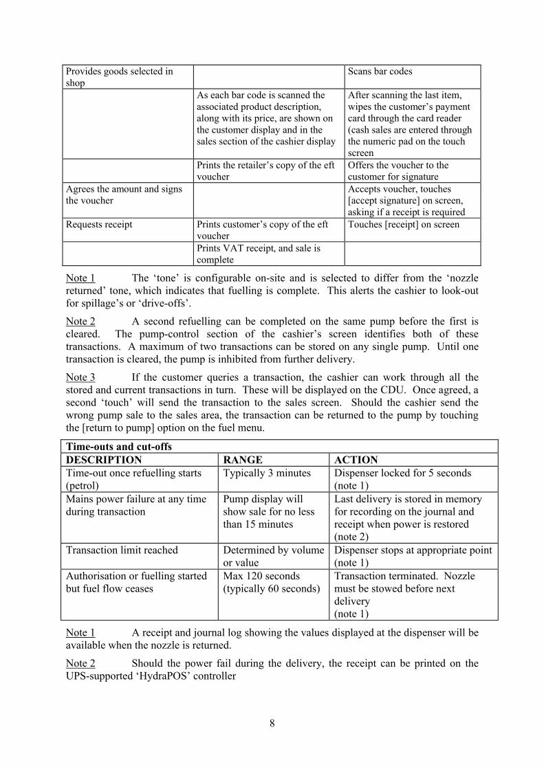
Provides goods selected in shop
Scans bar codes
As each bar code is scanned the associated product description, along with its price, are shown on the customer display and in the sales section of the cashier display
After scanning the last item, wipes the customer’s payment card through the card reader (cash sales are entered through the numeric pad on the touch screen
Prints the retailer’s copy of the eft voucher
Offers the voucher to the customer for signature
Agrees the amount and signs the voucher
Accepts voucher, touches [accept signature] on screen, asking if a receipt is required
Requests receipt Prints customer’s copy of the eft voucher
Touches [receipt] on screen
Prints VAT receipt, and sale is complete
Note 1 The ‘tone’ is configurable on-site and is selected to differ from the ‘nozzle returned’ tone, which indicates that fuelling is complete. This alerts the cashier to look-out for spillage’s or ‘drive-offs’.
Note 2 A second refuelling can be completed on the same pump before the first is cleared. The pump-control section of the cashier’s screen identifies both of these transactions. A maximum of two transactions can be stored on any single pump. Until one transaction is cleared, the pump is inhibited from further delivery.
Note 3 If the customer queries a transaction, the cashier can work through all the stored and current transactions in turn. These will be displayed on the CDU. Once agreed, a second ‘touch’ will send the transaction to the sales screen. Should the cashier send the wrong pump sale to the sales area, the transaction can be returned to the pump by touching the [return to pump] option on the fuel menu.
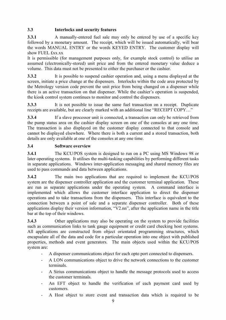
Time-outs and cut-offsDESCRIPTION RANGE ACTIONTime-out once refuelling starts (petrol)
Typically 3 minutes Dispenser locked for 5 seconds (note 1)
Mains power failure at any time during transaction
Pump display will show sale for no less than 15 minutes
Last delivery is stored in memory for recording on the journal and receipt when power is restored(note 2)
Transaction limit reached Determined by volume or value
Dispenser stops at appropriate point(note 1)
Authorisation or fuelling started but fuel flow ceases
Max 120 seconds(typically 60 seconds)
Transaction terminated. Nozzle must be stowed before next delivery(note 1)
Note 1 A receipt and journal log showing the values displayed at the dispenser will be available when the nozzle is returned.
Note 2 Should the power fail during the delivery, the receipt can be printed on the UPS-supported ‘HydraPOS’ controller
9
3.3 Interlocks and security features
3.3.1 A manually-entered fuel sale may only be entered by use of a specific key followed by a monetary amount. The receipt, which will be issued automatically, will bear the words MANUAL ENTRY or the words KEYED ENTRY. The customer display will show FUEL £xx.xxIt is permissible (for management purposes only, for example stock control) to utilise an assumed (electronically-stored) unit price and from the entered monetary value deduce a volume. This data must not be presented to either the purchaser or the cashier.
3.3.2 It is possible to suspend cashier operation and, using a menu displayed at the screen, initiate a price change at the dispensers. Interlocks within the code area protected by the Metrology version code prevent the unit price from being changed on a dispenser while there is an active transaction on that dispenser. While the cashier’s operation is suspended, the kiosk control system continues to monitor and control the dispensers.
3.3.3 It is not possible to issue the same fuel transaction on a receipt. Duplicate receipts are available, but are clearly marked with an additional line “RECEIPT COPY…”
3.3.4 If a slave processor unit is connected, a transaction can only be retrieved from the pump status area on the cashier display screen on one of the consoles at any one time. The transaction is also displayed on the customer display connected to that console and cannot be displayed elsewhere. Where there is both a current and a stored transaction, both details are only available at one of the consoles at any one time.
3.4 Software overview
3.4.1 The KCU/POS system is designed to run on a PC using MS Windows 98 or later operating systems. It utilises the multi-tasking capabilities by performing different tasks in separate applications. Windows inter-application messaging and shared memory files are used to pass commands and data between applications.
3.4.2 The main two applications that are required to implement the KCU/POS system are the dispenser controller application and the customer terminal application. These are run as separate applications under the operating system. A command interface is implemented which allows the customer interface application to direct the dispenser operations and to take transactions from the dispensers. This interface is equivalent to the connection between a point of sale and a separate dispenser controller. Both of these applications display their version information, “V2.nn”, after the application name in the title bar at the top of their windows.
3.4.3 Other applications may also be operating on the system to provide facilities such as communication links to tank gauge equipment or credit card checking host systems. All applications are constructed from object orientated programming structures, which encapsulate all of the data and code for a particular operation into one object with published properties, methods and event generators. The main objects used within the KCU/POS system are:
- A dispenser communications object for each opto port connected to dispensers.
- A LON communications object to drive the network connections to the customer terminals.
- A Sirius communications object to handle the message protocols used to access the customer terminals.
- An EFT object to handle the verification of each payment card used by customers.
- A Host object to store event and transaction data which is required to be
10
transmitted back to a central head office system (or 3rd party Back Office PC).
- A tank gauge object that sends sales data to the gauge and reads the dip levels.
- A loyalty object that determines points to be awarded to customers when this facility is enabled.
3.5 Software issue status and software security features
Software issue status is displayed is displayed in the top left-hand screen display when HydraPOS.exe is running. Issue status is “Metrology version code = 7CC888C4”. Software security features additional to those embedded within the operating system are as follows:
- A hierarchy of password access is required for all intervention at all levels.
- The applications that make up the KCU/POS and outdoor payment system are only present in executable machine code form. There are no high level or source code files available on the system which might allow unauthorised changes to the software.
- Transaction data is secure from manipulation by any common software tools.- The dispenser controller application maintains a data area on the system that
describes the current status of each dispenser and its transactions. This data can be read but cannot be modified by the application that handles the customer terminal and card payment operations.
- The system does not perform price to pay calculations. Unit price, volume and total price, are read from the dispenser head by the dispenser controller application and made available to the customer terminal application. Transaction values are stored independently by the dispenser control application and by the customer terminal application when the transaction is allocated to a particular payment card.
- Completed transaction data are stored separately in binary machine format and ASCII text format. Copies of both of these files are also maintained on a second disk drive normally located on a separate PC on the local area network.
- Transaction data is sent in encrypted form via ISDN to a remote host system. Transfer is normally carried out at 30-minute intervals.
3.6 Software Version and Metrology Code HistoryMetrology Code 7CC888F8 - Versions 4.3.0 to 4.3.6
Metrology Code 7CC8E0F8 (Changed with addition of DOMS) –Versions - 4.3.7 to 4.3.10
Metrology Code 7CC888F8 -Version 4.3.11
Metrology Code 2454B840 -Version 4.3.12 onwards.
4 AUTHORISED ALTERNATIVES
4.1 Alternative UPSs may be use, conforming to the following:
- Capable of supplying 500 VA or greater for at least 15 minutes.
- CE marked for safety and for EMC emissions/immunity.
- Having the capability to signal to KCU/POS that the mains input has failed.
- Capable of being set or adjusted for a trigger point of 186V AC (minimum allowable supply voltage less 10%)
11
4.2 HTEC Loyalty Server
Where a loyalty scheme is operated, an HTEC GALAXY unit may be connected. Loyalty card operation with the HTEC CRIND-OPT shall be as described within the referenced certification.
4.3 Alternative dispenser control interface units using USB connection:
1) ‘HTEC pump interface’2) ‘HTEC SC400 site controller’
As described in the certificate but having alternative site control interface arrangements described below.
Note: The arrangement described requires the use of PC based POS/KCU platforms with USB interface connection(s).
4.3.1 Description
4.3.1.1 The system as described in the certificate utilises a ‘Moxa’ PC plug-in assembly which couples the dispenser control signals via an external ‘opto-isolator’ interface unit. The alternatives described here dispense with use of the PC plug-in unit and combine the functions previously performed by both the plug-in assembly and the interface unit into the single assemblies detailed below. In each case, connection(s) to the KCU/POS PC are via USB termination. The site controllers detailed below may operate with any of the HydraPOS PC KCU/POS assemblies previously approved by means of USB connection.
4.3.1.2 HTEC pump interface unit, part number 950-00210-100
This site controller is designed to interface between a PC based POS/KCU system and forecourt dispensers and/or other forecourt equipment such as tank gauges, payment terminals, or car-wash installations. Connection to the KCU/POS is via a USB termination. Up to 8 connections to dispensers (or any connected equipment) are provided and these are configurable to provide the appropriate interface protocol and opto-isolation where specified. A typical system arrangement is shown in Figure 16. Views of the ‘pump interface unit’ are shown in Figures 14 and 15 and a functional block diagram of the unit is shown in Figure 16. One or more site of the site controllers described may be installed depending upon site requirements.
4.3.1.2.1 Having an alternative HTEC pump interface unit, part number 950-00251-101, also termed side A only controller, as shown in Figure 51. This version is as described above, but having 16 configurable “comm.” ports as standard. The side A only devices contain the same boards as the “EC resilient site controller” (4.3.1.3.1) however, the side A only does not have the switches nor the switchboard.
4.3.1.3 HTEC Hydra SC400 site controller, part number 950-00214-100
This site controller is similar to the ‘pump interface unit’ of Section 1.2 above, but incorporates two sets of USB connections with switchable interchange to provide selectable levels of recovery and operation in the event the failure of a POS or part of the controller. Up to 16 connections to dispensers (or any connected equipment) are provided and these are configurable to provide the appropriate interface protocol and opto-isolation where specified. A typical system arrangement is shown in Figure 20. Views of the ‘pump interface unit’ are shown in Figures 18 and 19.
4.3.1.3.1 Having the HTEC Hydra SC400 MkII site controller, part number 950-00251-100 (Resilient) also termed EC resilient site controller, as shown in Figure 52.
12
4.4 Alternative POS PCs:
1) Toshiba TEC ST-6501-C54C1-QM
2) TEC ST-60-C
3) Digipos MillenniumAs described in the certificate but having the alternative PC POS/KCU units described as follows:
4.4.1 Description
The system is as described in the certificate, but omits the ‘Moxa’ card and utilises instead a USB connection. PCs and systems are as detailed below. A typical system diagram is shown in Figure 17. Operation, interlock and security features, and software issue status, remain as described in the certificate. Additional POS units can be connected via means of LAN network and ‘Hub’unit.
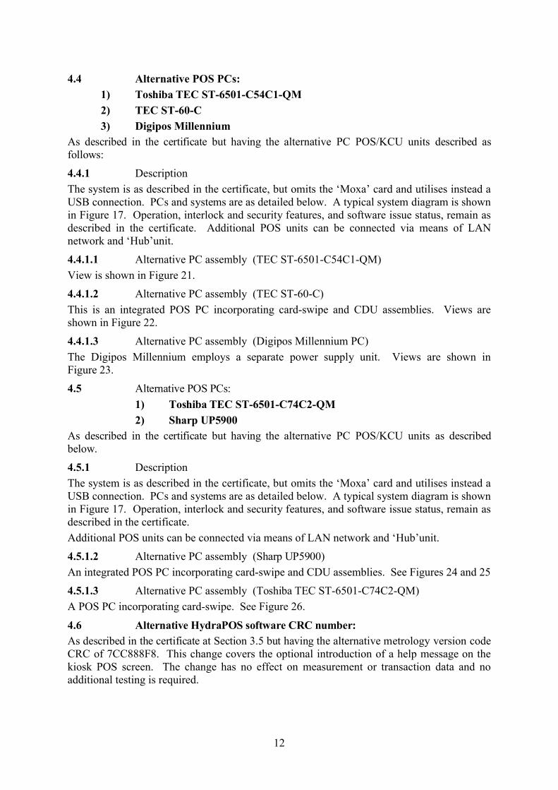
4.4.1.1 Alternative PC assembly (TEC ST-6501-C54C1-QM)
View is shown in Figure 21.
4.4.1.2 Alternative PC assembly (TEC ST-60-C)
This is an integrated POS PC incorporating card-swipe and CDU assemblies. Views are shown in Figure 22.
4.4.1.3 Alternative PC assembly (Digipos Millennium PC)
The Digipos Millennium employs a separate power supply unit. Views are shown in Figure 23.
4.5 Alternative POS PCs:
1) Toshiba TEC ST-6501-C74C2-QM
2) Sharp UP5900As described in the certificate but having the alternative PC POS/KCU units as described below.
4.5.1 Description
The system is as described in the certificate, but omits the ‘Moxa’ card and utilises instead a USB connection. PCs and systems are as detailed below. A typical system diagram is shown in Figure 17. Operation, interlock and security features, and software issue status, remain as described in the certificate.
Additional POS units can be connected via means of LAN network and ‘Hub’unit.
4.5.1.2 Alternative PC assembly (Sharp UP5900)
An integrated POS PC incorporating card-swipe and CDU assemblies. See Figures 24 and 25
4.5.1.3 Alternative PC assembly (Toshiba TEC ST-6501-C74C2-QM)
A POS PC incorporating card-swipe. See Figure 26.
4.6 Alternative HydraPOS software CRC number:As described in the certificate at Section 3.5 but having the alternative metrology version code CRC of 7CC888F8. This change covers the optional introduction of a help message on the kiosk POS screen. The change has no effect on measurement or transaction data and no additional testing is required.
13
4.7 Alternative POS PC: Epson MR 800 (Figures 27 and 28)
As described in the certificate but having the alternative PC POS/KCU unit as described below.
4.7.1 Description
The system is as described in the certificate, but omits the ‘Moxa’ card and utilises instead a USB connection. PCs and systems are as detailed below. A typical system diagram is shown in Figure 17. Operation, interlock and security features, and software issue status, remain as described in the certificate. A LAN network and ‘Hub’ unit allows connection of additional POS units as well as connection to ‘back-office’ or peripheral equipment.
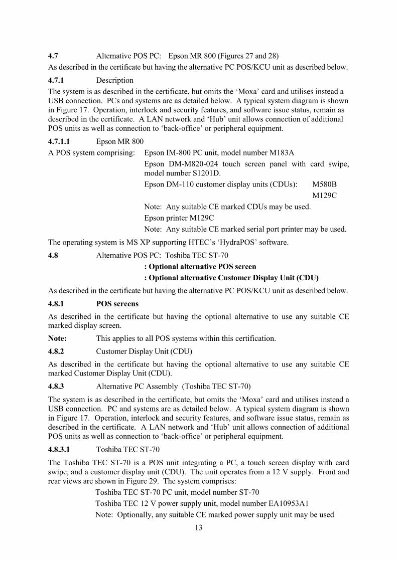
4.7.1.1 Epson MR 800
A POS system comprising: Epson IM-800 PC unit, model number M183A
Epson DM-M820-024 touch screen panel with card swipe, model number S1201D.
Epson DM-110 customer display units (CDUs): M580B
M129C
Note: Any suitable CE marked CDUs may be used.
Epson printer M129C
Note: Any suitable CE marked serial port printer may be used.
The operating system is MS XP supporting HTEC’s ‘HydraPOS’ software.
4.8 Alternative POS PC: Toshiba TEC ST-70
: Optional alternative POS screen
: Optional alternative Customer Display Unit (CDU)
As described in the certificate but having the alternative PC POS/KCU unit as described below.
4.8.1 POS screens
As described in the certificate but having the optional alternative to use any suitable CE marked display screen.
Note: This applies to all POS systems within this certification.
4.8.2 Customer Display Unit (CDU)
As described in the certificate but having the optional alternative to use any suitable CE marked Customer Display Unit (CDU).
4.8.3 Alternative PC Assembly (Toshiba TEC ST-70)
The system is as described in the certificate, but omits the ‘Moxa’ card and utilises instead a USB connection. PC and systems are as detailed below. A typical system diagram is shown in Figure 17. Operation, interlock and security features, and software issue status, remain as described in the certificate. A LAN network and ‘Hub’ unit allows connection of additional POS units as well as connection to ‘back-office’ or peripheral equipment.
4.8.3.1 Toshiba TEC ST-70
The Toshiba TEC ST-70 is a POS unit integrating a PC, a touch screen display with card swipe, and a customer display unit (CDU). The unit operates from a 12 V supply. Front and rear views are shown in Figure 29. The system comprises:
Toshiba TEC ST-70 PC unit, model number ST-70
Toshiba TEC 12 V power supply unit, model number EA10953A1
Note: Optionally, any suitable CE marked power supply unit may be used
14
Toshiba TEC ST-70 touch screen panel with card swipe
Toshiba TEC ST-70 integrated customer display units (CDUs)
Toshiba TEC receipt printer TRST-56-S-1G-QM
Note: Optionally, any suitable CE marked serial port printer may be used
The operating system is MS Windows 2000 professional supporting HTEC’s ‘HydraPOS’software. The front mounted connection panel is shown in Figure 30. This is normally protected with a plastic cover. Figure 31 shows the TEC printer.
4.9 Epson MR 800 (IM-800, M183A), Alternative PSU with 24 V dc output
4.9.1 Epson MR 800 (IM-800, M183A) as described in the certification, but having fitted an alternative Power Supply Unit (PSU) providing a 24 V dc output suitable for supplying printers and/or till units, or any device requiring 24 V dc.
4.9.2 The modified power supply unit has the part number Delta Electronics INC DPS-180MB-2 XX (where XX=0-9, A-Z or blank). A view of the back panel (cover shown removed) is shown in Figure 32.
4.10 Optional alternative POS unit: Epson IR 700As described in the certification, but having the option to use the Epson IR 700 POS unit as described below and as shown in Figures 33 and 34 of this amendment.
Alternative PC Assembly (Epson IR 700) POS system comprising of the following:
Epson IM 700 PC base unit, model number M215A
Epson DM-LX121SV touch screen panel model number M217A.
Epson 3 track magnetic stripe reader (MSR).
Epson DM-D210 Customer Display Units (CDUs): M59DB
Note: Any suitable CE marked CDUs may be used.
Epson printer TM-T88IIIX, model M216A
Note: Any suitable CE marked serial port printer may be used.
4.11 Alternative POS PC: Toshiba TEC ST-71 and Toshiba TEC ST-7000
As described in the certificate but having the alternative PC unit as described below.
4.11.1 The system is as described in the certificate, but omits the ‘Moxa’ card and utilises instead a USB connection. PC and systems are as detailed below. A typical system diagram is shown in Figure 35. Operation, interlock and security features, and software issue status, remain as described in the certificate. A LAN network and ‘Hub’ unit allows connection of additional POS units as well as connection to ‘back-office’ or peripheral equipment.
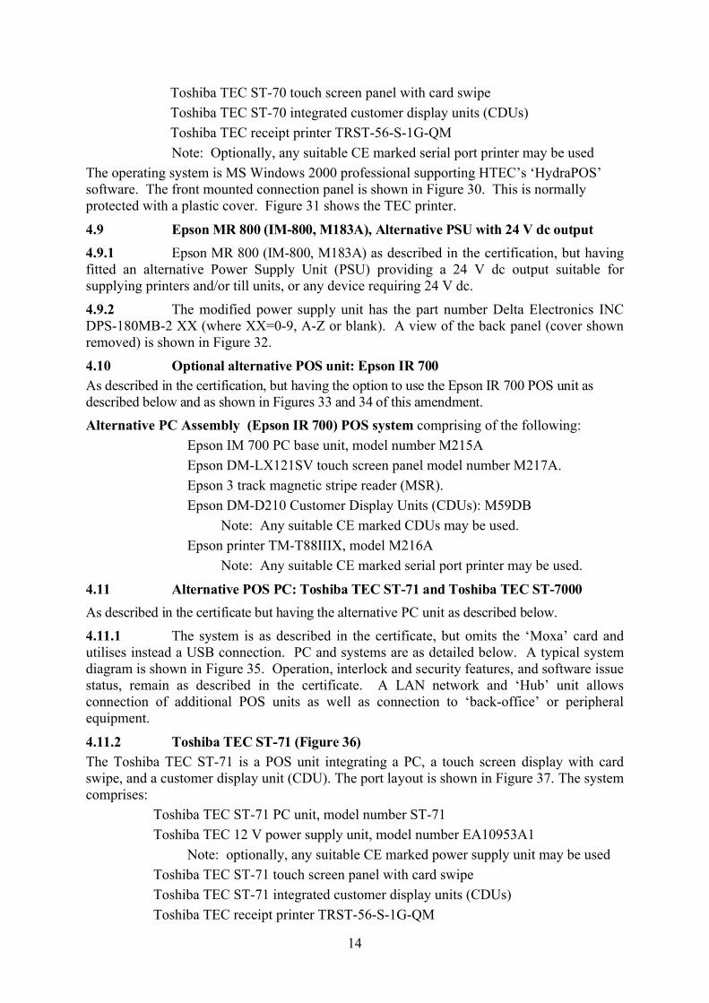
4.11.2 Toshiba TEC ST-71 (Figure 36)The Toshiba TEC ST-71 is a POS unit integrating a PC, a touch screen display with card swipe, and a customer display unit (CDU). The port layout is shown in Figure 37. The system comprises:
Toshiba TEC ST-71 PC unit, model number ST-71
Toshiba TEC 12 V power supply unit, model number EA10953A1
Note: optionally, any suitable CE marked power supply unit may be used
Toshiba TEC ST-71 touch screen panel with card swipe
Toshiba TEC ST-71 integrated customer display units (CDUs)
Toshiba TEC receipt printer TRST-56-S-1G-QM
15
Note: Optionally, any suitable CE marked serial port printer may be used
4.11.3 Toshiba TEC ST-7000 (Figure 38)
The Toshiba TEC ST-7000 PC unit may have connected any CE marked operator display, Customer display and serial port printer. The rear view of the unit is shown in Figure 39.
4.12 Alternative POS PC: DigiPoS Retail Blade and DigiPoS PH6000T
As described in the certificate but having the alternative PC units as described below. The PCs may have any peripheral equipment connected identified in the certificate.
4.12.1 The DigiPoS Retail Blade™ (Figure 40)
The DigiPoS Retail Blade™ processor module is PC-based, using an Intel™ Pentium processor. Its features are:
Intel™ Celeron 2.0GHz up to P4 3.8GHz processor.
Up to 2GBytes of internal Compact Flash memory.
Up to 2GBytes of internal RAM.
Any 3.5 inch standard hard disk (IDE/EIDE/SCSI/S-ATA)
A lockable front bezel to secure the Retail Blade™. The key for this is held by a responsible person, for example a service engineer.
4.12.2 PH6000T POS PC System (Figure 41)
The system is made up of three main sub-systems:
Main System Unit
I/O Base Unit
Power Supply Unit
4.12.2.1 Main system unit
The DigiPoS PH6000T processor module is PC-based, having the SBC 84810 embedded motherboard with Intel Celeron M 1GHz processor using the Intel 852GM Chipset.
4.12.2.2 The Base I/O Unit
All standard PoS signals are routed through the Base I/O unit. It has the same footprint as the Main system unit.
4.12.2.3 Power Supply Unit
The DigiPoS power supply unit type PSS-2000 or PSS-250.
4.13 Alternative POS PC : DigiPoS Retail Blade Core2 Duo
As described in the Certificate but the Digipos Retail Blade having an Intel™ Celeron 2.0 GHz up to P4 3.8 GHz processor and including Intel™ Core2 Duo processors E4300 and E6400, this alternative is named; “DigiPoS Retail Blade Core2 Duo”.
4.14 Alternative POS PC : Toshiba TEC ST A-10
As described in the certificate but having the alternative POS PC designated TEC ST A-10manufactured by Toshiba. The PC may have any peripheral equipment connected identified in the certificate.
This is a PC based electronic till having an LCD touch screen operator display with a built-in card swipe.
16
4.14.1 Alternative POS PC Toshiba TEC ST B-10
As described in the certificate but having the alternative POS PC designated TEC ST B-10manufactured by Toshiba This is a modular PC based electronic till having a separate LCD/monitor; Printer, Drawer and Keyboard. The PC may have any peripheral equipment connected that is identified in this certificate.
4.15 Alternative site Controller: DOMS PSS 5000
The HydraPOS system is as described in the certificate but the Hydra PC assembly ‘server’ interfaced with the ‘opto’ (KCU) unit is replaced with the DOMS PSS 5000 site controller. The system schematic is shown in Figure 42.
4.15.1 Forecourt controller DOMS
The DOMS PSS5000 forecourt controller comprises a metal rectangular box housing the following main components. The general arrangement is shown in Figure 43.
A power supply
A Central Processing Board (CPU) with 8 serial ports (CPB508):this has an LCD 16x2 character alphanumerical display and a keyboard comprising 5 keys for navigating the menu options. An adjacent legend describes the key functions, as shown in Figure 44.
Hardware interface modules:dispensers are connected to the CPU board via an appropriate hardware interface module compatible with the communication protocol of the dispenser.
4.15.2 DOMS Software
The DOMS PSS5000 has a legal authority module (LAM) for the UK containing specific parameter values and functions. Reference to the PSS 5000 software version number is not normally required, but may be accessed as follows: typical LAM version number is 498-06-100 and 0D6C for the checksum number. These can be viewed by selecting the appropriate menu heading using the operator keys on the CPU. The LAM version number and checksum are accessed as follows:
When the PSS is powered on, the first line displays the application software version and the current time. The second line displays the W&M Service menu. Pressing the Down Arrow once, displays the W & M menu, which comprises 7 sub-menus, W.1 to W.7. Press the right button once to obtain W.1 – LAM INFO and press again to display Version and Checksum information.
4.15.3 HydraPOS Software
As described in the certificate at Section 3.5, but having the alternative liquid metrology version code CRC of 2454B840. This change covers the software modifications required to communicate with the PSS DOMS 5000 as an alternative site controller. This metrology version can also be used with the HTEC Pump Interface unit and the HTEC Site Controller.
4.15.4 DOMS PSS 5000 and HTEC Outdoor Payment Terminal (OPT) without the HydraPOS KCU/POS functionality.
As described in section 2.8, but without the connection of an HTEC HydraPOS KCU/POS system and having the alternative liquid metrology version code CRC of DC5CD460.
In this mode of operation the KCU/POS function is not used and the touch-screen POS unit can be replaced with a standard approved PC listed in section 2.8. The system connectivity is still the same as that shown in Figure 42, with the exception that the touch-screen POS unit
17
can be replaced by a standard PC.
Note: The system described in this section may be used alongside a third party KCU/POS that also uses the DOMS as a site controller providing the KCU/POS certification makes reference to this approval.
4.16 Alternative POS PC : Toshiba TEC STB-20
As described in the certificate but having the alternative POS PC designated TEC STB-20 manufactured by Toshiba. The PC unit may have connected any CE marked operator display, Customer display and serial port printer.
4.17 Alternative POS PC: Toshiba model ST-A20
As described in the certificate but having the alternative POS PC designated ST-A20 manufactured by Toshiba. These are PC based electronic tills having an LCD touch screen operator display with a built-in card swipe.
5 RECOMMENDED TESTS
The following tests may be carried out in addition to those specified for the approved pattern and those detailed in the appropriate certification for the associated payment terminals.
5.1 Verify that the sequence of operation is generally as described in the tables of Section 3.
5.2 Where Payment Terminals are fitted, check that a receipt is available from the terminals on completion of delivery.
5.3 Check that for all transactions, the volume and price indicated on the dispenser display correspond to those shown on receipts and recorded on the journal display.
5.4 Verify that software issue is as described in Section 3.6.
6 HTEC SIRIUS CRIND CARD READER
6.1 IntroductionThe CRIND-SIRIUS terminal is a double-sided unit, normally sited conveniently for use with the associated dispenser. A general view of the payment terminal is shown in Figure 45 and a typical screen display is shown in Figure 46.
The payment method may be selected prior to delivery of the fuel: - at the CRIND-SIRIUS terminal (by presentation of a suitable valid payment card) or alternatively at the kiosk (by pressing the “NO” [PAY AT KIOSK] button on the terminal).
6.1.1 Control equipmentOne or more CRIND-SIRIUS terminals are controlled by the HydraPos combined kiosk control unit and point of sale terminal.
The CRIND-SIRIUS terminals are associated with particular fuel dispensers but do not directly control those dispensers. Control of the dispenser’s remains with the HYDRAPOS system.
6.2 CONSTRUCTION
6.2.1 Mounting The payment terminal is designed to be mounted near to the dispenser display head, either by direct attachment to the structure of the dispenser or to a metal post or column mounted adjacent to the dispenser.
The terminal is mounted such that the keypad, display, card entry slot and receipt chute, face the same way as the associated dispenser display.
18
6.2.2 MechanicalThe CRIND-SIRIUS terminal is mainly of steel construction. A wrap-over steel cover encloses an internal steel chassis on which the functional components are mounted. A front panel (one either side) is painted to match site requirements and bears a user instruction label. The front panel has a lockable hinged panel allowing access to the printer paper roll holder. A lockable hinged panel underneath the terminal allows access to remove retained payment cards. Dimensions are as follows:- width 469 mm, depth (face to face) 607 mm, height 263 mm.
6.2.2.1 Front panel
The top section of the panel comprises a window onto a large monochrome LCD display panel. Monochrome plasma or colour LCD panels may be fitted as alternatives.Beside the display are two “soft” control buttons (see Figure 46). These buttons have various functions ascribed to them in accordance with operational requirements: indication of the current function is shown on the adjacent screen display. The main uses for these buttons are the “YES” (PAY AT PUMP) and “NO” (PAY AT KIOSK) functions.
The lower portion of the panel holds a general-purpose alphanumeric keypad. A large “HELP” button is present in the bottom right-hand corner.
The printed receipts are delivered via a slot at the left of the panel
6.2.2.2 Terminal functional description (see Figure 47)
Most components are duplicated to achieve the double-sided design. Each side has the following major components:
(i) An electronic control board, the HTEC SIRIUS GALAXY CARD, controls the local operation of the unit and interfaces, via an embedded PC card, the data link to the HYDRAPOS combined kiosk control unit and point of sale terminal. The Galaxy card is employed for its I/O capability and does not carry out any ‘loyalty terminal’ functions.
(ii) A separate electronic control board activates a thermal printer mechanism according to instructions it receives from the SIRIUS GALAXY CARD. The thermal printer controls include a guillotine to separate and allow the printed receipt to be withdrawn from the unit. A paper presenter mechanism transports the cut receipt from the guillotine to the customer: this ensures that the customer pulling on the receipt as it emerges from the slot cannot upset the printing process.
(iii) To the rear of the printer mechanism is a paper roll holder. Access to replace the paper roll is via the front panel of the terminal. A paper-low detector is used to ensure that transactions cannot proceed when there is insufficient paper left to print a receipt.
(iv) A motorised card mechanism is used to read credit/debit card details. The card mechanism may also be used to write data to loyalty cards. An optional addition to the card mechanism will allow the reading and writing of smart cards (chip cards) via the electrical contact pattern on those cards.
(v) For security purposes the terminal may be instructed to retain the card. In this case the card is ejected backwards from the card mechanism into a hopper area accessible through a locked panel in the base of the unit.
(vi) The displays are controlled by a single embedded PC, which serves both sides of the terminal. Displays are of the graphics type where words and images are built up from patterns of small dots. Character sizes are software defined and are set to a size appropriate to the message content. The CRIND-SIRIUS terminal does not display transaction volume or value. Where loyalty points transaction totals are displayed, characters are not less that 10 mm high.
19
(vii) The display is intended to be visible in a wide range of lighting conditions (including direct sunlight). For the LCD option, an illumination panel behind the display ensures visibility in low light conditions.
(viii) Two loudspeakers are fitted internally, controlled by the embedded PC card via a small amplifier module. The loudspeakers may be used to give pre-recorded instruction or warnings to customers.
(ix) An Echelon/Lonworks module receives commands from and sends data to the HydraPos system. Commands and data are routed by the embedded PC card to the appropriate SIRIUS GALAXY card or display.
(x) AC-DC power supplies provide low voltage DC power to the main functional components. A voltage converter is used to drive the display illumination panel, powered from the low voltage DC supply.
6.2.3 Journal logThe journal log for card transactions carried out at the CRIND-SIRIUS terminal is held on the hard disc drive in the file server of the HYDRAPOS system. Access and management of the journal log is subject to the same conditions as for transactions performed within the kiosk.
6.2.4 SealingThe CRIND-SIRIUS terminal does not perform metrological functions and is therefore not fitted with the means to apply seals. Access to replace receipt rolls or to release retained cards is by means of key operated access panels.
6.2.5 Serial data link The serial data link from the CRIND-SIRIUS terminal to the HYDRAPOS system is as shown in Figure 4 and utilises the Echelon/Lonworks LON network. The network may be shared with dispensers and other forecourt equipment. Current loop dispensers connect to the HydraPos via a standard HTEC multi-channel opto-isolator unit. Serial data from the HydraPos is coupled via the opto-isolator unit and is then coupled via a Protocol Converter unit (Part Number 950-00170-100, see Figure 49) which converts this serial data to L.O.N format for connection to the SIRIUS CRIND via the network.
6.3 OPERATION
6.3.1 Controls and featuresNote: The following controls and features are specific to the operation of the CRIND-SIRIUS terminal in conjunction with the HYDRAPOS combined kiosk control and point of sale terminal system.
All though the CRIND-SIRIUS terminal contains processing capability the use of this processing power is mainly under the control of the HYDRAPOS system.
6.3.1.1 Site configuration
With the CRIND-SIRIUS terminal connected to the HYDRAPOS system, the associated dispenser may be controlled by one of the following methods:
(i) Authorisation by the system without operator intervention upon validation of a card inserted into the CRIND-SIRIUS terminal.
(ii) Authorisation, by the operator, at the kiosk console after validation by the system of a card inserted into the CRIND-SIRIUS terminal.
(iii) Authorisation by the operator at the kiosk console after either validation of a card inserted at the CRIND-SIRIUS terminal, or selection by the customer to pay at kiosk by pressing the appropriate button on the CRIND-SIRIUS terminal.
(iv) Authorisation by the system without operator intervention upon validation of a card inserted into the CRIND-SIRIUS terminal or authorisation by the operator
20
at the kiosk console after selection by the customer to pay at kiosk by pressing the appropriate button on the CRIND-SIRIUS terminal.
In consideration of fire and other safety factors, one or more of the above methods of control may be inhibited. Such inhibition forms part of the site configuration at installation and is not re-programmable by site personnel.
6.3.1.2 CRIND-SIRIUS terminal
CRIND-SIRIUS has the following features:
(i) A motorised card readerCards will be ejected back to the purchaser if they are not readable (e.g. the card was inserted the wrong way up). In this case a message will be displayed offering the purchaser another opportunity to insert the card correctly.
Cards, which are readable but not recognised as valid types for use at the site, will be ejected back to the purchaser and an error message will be displayed.
Attempts to use a loyalty card for payment or a payment type (credit/debit/agency) card to save loyalty points will be ejected and an appropriate error message will be displayed.
Cards of any type, which are recognised to be on a “hot list” of duplicate or fraudulent cards, will be retained and an appropriate error message displayed.
(ii) A rectangular high-brightness display
(iii) A 41-button alphanumeric keypad including "ENTER", "EJECT" and "CANCEL" buttons. The "CANCEL" button may be used by the purchaser to cancel a transaction before taking fuel
(iv) Two additional "soft" (programmable function) buttons are used, situated adjacent to the display (see Figure 46). These, in conjunction with messages and identifications on the display, are used by the purchaser to select the method of payment required.
(v) A receipt printer. The receipt is delivered via a chute protruding through the front panel of the terminal. Access to the receipt printer paper roll is via a key operated panel in the terminal. A typical receipt is shown in Figure 50.
6.3.1.3 Dispenser and console
The HYDRAPOS combined kiosk control unit and point of sale terminal, controls and authorises the dispensers. The HYDRAPOS system is connected to the CRIND-SIRIUS terminal by a data link.
When a payment card is inserted into the CRIND-SIRIUS terminal the card data is read, decoded and sent to the HYDRAPOS system. The HYDRAPOS system checks that the dispenser is available for CRIND-SIRIUS operation and that the payment card is valid (i.e. correct type, not on a "hot list" and not past its expiry date) for the proposed transaction. The HYDRAPOS system will determine from the card data and records of previous transactions that day, what restrictions to impose on the dispenser when it is authorised. At the end of fuelling the transaction information is logged onto the HYDRAPOS MASTER PROCESSOR UNIT harddisc. The transaction information is formatted and sent to the CRIND-SIRIUS terminal for the printing of a receipt.
The operator's display information shown in the pump information box of the HYDRAPOS system terminal display also shows the current status of the CRIND-SIRIUS terminal associated with that pump.If a pre-payment transaction is active at the dispenser then any transactions involving the CRIND-SIRIUS terminal are inhibited.
6.3.1.4 Unattended mode
21
The Foremost HYDRA-Unattended system (HYDRA-U) (Figure 54) is a kiosk control unit intended for use on unattended forecourts where fuel sales are transacted at outdoor payment terminals, such as the HTEC CRIND-Sirius, with no operator intervention required. The Foremost HYDRA-U system is designed to provide flexibility with the provision and function of peripheral units.
The Foremost HYDRA-U system includes communications links via ISDN (and optionally MODEM connections) which allow the checking of credit/payment/fuel cards with the appropriate remote authorisation databases and collection of all transaction data by a remote head office. Fault diagnosis and software updates may also be performed via the communications links, minimising the requirement for site visits. A typical HYDRA–U set up is shown in Figure 55.
The Foremost HYDRA-U installation will normally comprise two processor units with associated interfaces, each servicing one half of the forecourt and with each backing-up the data held on the other. In this way, the data is always backed-up and the forecourt may continue to function (at half capacity) in the event of failure of one processor unit or its ancillary equipment. A typical system set-up is shown in Figure 56.
Connection of the Foremost HYDRA-U system to the forecourt equipment may be by optically isolated current loop, voltage signalling, RS232 or IFSF-LON according to the dispensers and equipment to be controlled.
Note: Approved dispenser interface is 2 wire, serial data, current loop.
6.3.1.4.1 Construction6.3.1.4.1.1 Processor unit (HTEC part number V4679 – Hydra-U)
The processor unit is based on an Intel Celeron/PentiumIII socket-370 motherboard in a desk-top PC enclosure. The front of the unit contains power and reset switches and gives access to the CD-ROM drive and to the (optional) 3.5” floppy disc drive. The back panel of the unit contains the mains power input, peripheral power outputs and access to the connectors of the motherboard and to the ports and plug-in adapter cards.
The processor unit contains the following major components:
(i) Power supply
(ii) Motherboard - This is a multi-layer PCB supporting a Pentium II/III class processor and DIMM module memory. The systems operates with an Intel Celeron 433 or 466MHz (or faster) processor. Two RS232 serial, one parallel, and one SVGA video ports are built in. Games ports, audio I/O etc may be present but are not used. PCI expansion slots on the motherboard allow inclusion of serial communications, ISDN and optionally MODEM adapter cards.
(iii) Disc drives - A hard disc of at least 4.3 gigabyte capacity is fitted to store the operating system, Foremost HYDRA-U application programs and transaction data files.
(iv) A CD-ROM drive is provided to allow loading of the operating system (Microsoft Windows NT4. Optionally, a single 3.5” floppy drive may also be fitted
(v) 8-port communications card - This is a PCI adapter card supporting eight RS232 serial channels. A 62-way cable connects this card to the opto- isolator/filter unit.
(vi) Local Area Network adapter card - The LAN card is an Ethernet device and is used to communicate between the two processor units of a typical Foremost HYDRA-U installation. An optional connection to a back-office PC supplied by a third party may also be made.
The LAN is implemented with CAT-5 cable connection via RJ45 connectors, or ThinNet (10BASE-2) coaxial cable connections via BNC connectors.
22
Although not needed for normal operation, screen, keyboard and mouse will be retained on site for set-up and maintenance purposes.
6.3.1.4.1.2 Uninterruptible power supply (UPS)
As described in section 2.6. Separate UPS units supply each processor unit. UPS requirements are as described in 4.2
6.3.1.4.1.3 Opto-isolator unit (part number 950-00178-100) (Figure 10)
As described in section 2.7. The opto-isolator interface card(s) receive RS232 signals from the Foremost HYDRA-U processor unit via a 62-way cable
For each output, the isolated power supply is protected by self-resetting fuses and by transient and over-voltage protection devices.
6.3.1.4.1.4 RS232 / LON Interface Unit (Part Number 950-00170-100) (Figure 12)
The HTEC CRIND-Sirius Outdoor Payment Terminal utilises the IFSF (LON) local area network connection. In order to interface with the control PC, an RS232 to IFSF (LON) converter is required. The unit as part of a system is shown schematically in Figures 55 and 56.The interface is implemented in a small metal enclosure containing a RS232 to LON converter and is connected to the processor unit via an RS232 port on the Opto-Isolator Unit. The IFSF (LON) Interface Unit is powered from a plug-top transformer (Part Number 961009BU) which receives its mains input from a supply controlled by the forecourt Fireman’s switch.
6.3.1.4.1.5 Outdoor payment terminal (OPT)
The HTEC CRIND-Sirius outdoor payment terminal may be used (see Section 6.4 for Alternatives).
For unmanned operation, the OPT will only allow payment to be made at the pump and the option of paying at the kiosk is disabled.
All transactions must be authorised by the HYDRA-U processor unit, which may check credit card validity etc, before allowing the transaction to proceed. On completion of the transaction, a receipt slip is printed-out by the OPT printer. For pay-at-kiosk option, the OPT unit plays no further part.
Communication between the outdoor payment terminal and the processor unit is as follows:
HTEC CRIND- Sirius IFSF (LON)Gilbarco CRIND 45mA current loopWayne ICR RS485 serial link
6.3.1.4.1.6 Tank gauges
Connection to most tank gauge types is supported. The processor unit interrogates the tank gauge, usually on a periodic basis. The tank gauge may also receive data on fuel volume sold from the processor unit. Communications between the processor unit and the tank gauge is via a serial link from the opto-isolator unit.
6.3.1.4.1.7 Car wash terminal
Connection to various types of car wash terminal is supported. The processor unit sends a command to the car wash terminal to allow activation when the customer requests and pays for a car wash during a transaction. The car wash terminal may be interrogated by the processor unit as required to reconcile car wash payments against operations performed. Communications between the processor unit and the car wash terminal is via a serial link from the opto-isolator unit.
6.3.1.4.1.8 Back office computer
23
The Foremost HYDRA-U system is designed so that a separate Back Office Computer is not necessary for normal operation. Certain sites may utilise a 3rd-party Back Office Computer for data processing and collection; in this case the Back Office computer will be connected to the HYDRA-U system by the Ethernet link.
6.3.1.4.2 OPERATION
6.3.1.4.2.1 Controls and features
6.3.1.4.2.1.1 The following describes the operation of the Foremost HYDRA-U system in conjunction with the HTEC CRIND-SIRIUS outdoor payment terminal. Operation with other outdoor payment terminals will be broadly similar but specific details may be changed according to the facilities available on the particular terminal in use.
6.3.1.4.2.1.2 Although the CRIND-Sirius terminal contains processing capability, the use of this processing power is mainly under the control of the HYDRA-U system.
6.3.1.4.2.1.3 The dispenser is authorised and controlled by the HYDRA-U system, which is connected to the CRIND-Sirius outdoor payment terminal by a separate data link.
6.3.1.4.2.1.4 When a payment card is inserted into the CRIND-Sirius terminal, the card data is read, decoded and sent to the HYDRA-U system which checks that the dispenser is available for CRIND-Sirius operation and that the payment card is valid (i.e. correct type, not on a “hot list” and not past its expiry date) for the proposed transaction. The HYDRA-U system will determine from the card data and records of previous transactions that day, what restrictions to impose on the dispenser when it is authorised. Following authorisation and completion of fuelling, the transaction information is logged onto the HYDRA-U system hard disc and the transaction information is formatted and sent to the CRIND-Sirius terminal for the printing of a receipt.
6.3.1.5 Software overview
6.3.1.5.1 The HYDRA-U outdoor payment system is designed to run on a PC under Windows NT4 operating system. It utilises the multi-tasking capabilities of Windows NT4 by performing different tasks in separate applications. Windows inter-application messaging and shared memory files are used to pass commands and data between applications.
6.3.1.5.2 The main two applications that are required to implement the HYDRA-U system are the dispenser controller application and the customer terminal application. These are run as separate applications under the operating system. A command interface is implemented which allows the customer interface application to instruct the dispenser controller to authorise or stop a dispenser and take transactions from the dispenser etc. This interface is equivalent to the connection between a point of sale and a separate dispenser controller. Both of these applications display their version information, “V2.nn”, after the application name in the title bar at the top of their windows.
6.3.1.5.3 Other applications may also be operating on the system to provide facilities such as communication links to tank gauge equipment or credit card checking host systems. All applications are constructed from object orientated programming structures, which encapsulate all of the data and code for a particular operation into one object with published properties, methods and event generators. The main objects used within the HYDRA-U system are: -
- A dispenser communications object for each opto port connected to dispensers.
- A LON communications object to drive the network connections to the customer terminals.
24
- A Sirius communications object to handle the message protocols used to access the customer terminals.
- An EFT object to handle the verification of each payment card used by customers.
- A Host object to store event and transaction data which is required to be transmitted back to a central head office system (or 3rd party Back Office PC).
- A tank gauge object that sends sales data to the gauge and reads the dip levels.
- A loyalty object that determines points to be awarded to customers when this facility is enabled.
6.3.1.6 Software issue status and software security features
Software issue status is displayed is displayed in the top left-hand screen display when Hydraproj.exe is running. Issue status is “Hydra V2.01”. Software security features additional to those embedded within the Windows NT4 operating system are as follows:
- Equipment is primarily intended for unmanned sites and the HYDRA-U PC would be situated within a locked and alarmed site building. Casual unauthorised access is thus precluded.
- A hierarchy of password access is required for all intervention at all levels.
- The applications that make up the HYDRA-U outdoor payment system are only present in executable machine code form. There are no high level or source code files available on the system which might allow unauthorised changes to the software.
- Transaction data is secure from manipulation by any common software tools.
- The dispenser controller application maintains a data area on the system that describes the current status of each dispenser and its transactions. This data can be read but cannot be modified by the application that handles the customer terminal and card payment operations.
- The system does not perform price to pay calculations. Unit price, volume and total price, are read from the dispenser head by the dispenser controller application and made available to the customer terminal application. Transaction values are stored independently by the dispenser control application and by the customer terminal application when the transaction is allocated to a particular payment card.
- Completed transaction data are stored separately in binary machine format and ASCII text format. Copies of both of these files are also maintained on a second disk drive normally located on a separate PC on the local area network.
- Transaction data is sent in encrypted form via ISDN to a remote host system. Transfer is normally carried out at 30-minute intervals.
6.3.2 Sequence of operations6.3.2.1 Payment at the CRIND-SIRIUS terminal
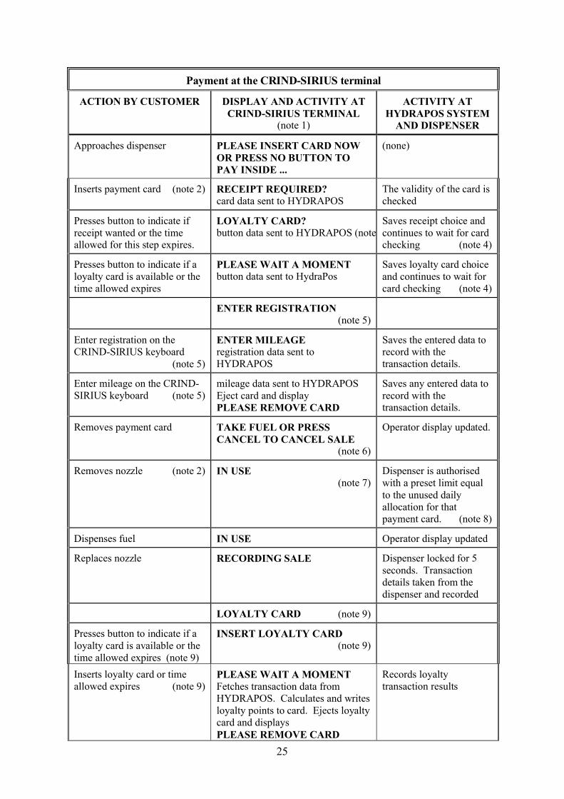
Payment at the CRIND-SIRIUS terminal
ACTION BY CUSTOMER DISPLAY AND ACTIVITY AT CRIND-SIRIUS TERMINAL
(note 1)
ACTIVITY AT HYDRAPOS SYSTEM
AND DISPENSER
25
Payment at the CRIND-SIRIUS terminal
ACTION BY CUSTOMER DISPLAY AND ACTIVITY AT CRIND-SIRIUS TERMINAL
(note 1)
ACTIVITY AT HYDRAPOS SYSTEM
AND DISPENSER
Approaches dispenser PLEASE INSERT CARD NOW OR PRESS NO BUTTON TO PAY INSIDE ...
(none)
Inserts payment card (note 2) RECEIPT REQUIRED? card data sent to HYDRAPOS
The validity of the card is checked
Presses button to indicate if receipt wanted or the time allowed for this step expires.
LOYALTY CARD?button data sent to HYDRAPOS (note 3)
Saves receipt choice and continues to wait for card checking (note 4)
Presses button to indicate if a loyalty card is available or the time allowed expires
PLEASE WAIT A MOMENTbutton data sent to HydraPos
Saves loyalty card choice and continues to wait for card checking (note 4)
ENTER REGISTRATION (note 5)
Enter registration on the CRIND-SIRIUS keyboard
(note 5)
ENTER MILEAGEregistration data sent to HYDRAPOS
Saves the entered data to record with the transaction details.
Enter mileage on the CRIND-SIRIUS keyboard (note 5)
mileage data sent to HYDRAPOSEject card and displayPLEASE REMOVE CARD
Saves any entered data to record with the transaction details.
Removes payment card TAKE FUEL OR PRESS CANCEL TO CANCEL SALE
(note 6)
Operator display updated.
Removes nozzle (note 2) IN USE(note 7)
Dispenser is authorised with a preset limit equal to the unused daily allocation for that payment card. (note 8)
Dispenses fuel IN USE Operator display updated
Replaces nozzle RECORDING SALE Dispenser locked for 5 seconds. Transaction details taken from the dispenser and recorded
LOYALTY CARD (note 9)
Presses button to indicate if a loyalty card is available or the time allowed expires (note 9)
INSERT LOYALTY CARD(note 9)
Inserts loyalty card or time allowed expires (note 9)
PLEASE WAIT A MOMENTFetches transaction data from HYDRAPOS. Calculates and writes loyalty points to card. Ejects loyalty card and displaysPLEASE REMOVE CARD
Records loyalty transaction results
26
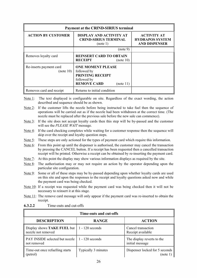
Payment at the CRIND-SIRIUS terminal
ACTION BY CUSTOMER DISPLAY AND ACTIVITY AT CRIND-SIRIUS TERMINAL
(note 1)
ACTIVITY AT HYDRAPOS SYSTEM
AND DISPENSER
(note 9)
Removes loyalty card REINSERT CARD TO OBTAIN RECEIPT (note 10)
Re-inserts payment card (note 10)
ONE MOMENT PLEASEfollowed byPRINTING RECEIPTfollowed byREMOVE CARD (note 11)
Removes card and receipt Returns to initial condition
Note 1: The text displayed is configurable on site. Regardless of the exact wording, the action described and sequence should be as shown.
Note 2: If the customer lifts the nozzle before being instructed to take fuel then the sequence of operations will be carried out as if the nozzle had been withdrawn at the correct time. (The nozzle must be replaced after the previous sale before the new sale can commence).
Note 3: If the site does not accept loyalty cards then this step will be by-passed and the customer will see the PLEASE WAIT message.
Note 4: If the card checking completes while waiting for a customer response then the sequence will skip over the receipt and loyalty question steps.
Note 5: These steps are only actioned for the types of payment card which require this information.
Note 6: From this point up until the dispenser is authorised, the customer may cancel the transaction by pressing the CANCEL button. If a receipt has been requested then a cancelled transaction receipt will be printed. Otherwise a receipt can be obtained by re-inserting the payment card.
Note 7: At this point the display may show various information displays as required by the site.
Note 8: The authorisation may or may not require an action by the operator depending upon the particular site configuration.
Note 9: Some or all of these steps may be by-passed depending upon whether loyalty cards are used on this site and upon the responses to the receipt and loyalty questions asked now and while the payment card was being checked.
Note 10: If a receipt was requested while the payment card was being checked then it will not be necessary to reinsert it at this stage.
Note 11: The remove card message will only appear if the payment card was re-inserted to obtain the receipt.
6.3.2.2 Time-outs and cut-offs
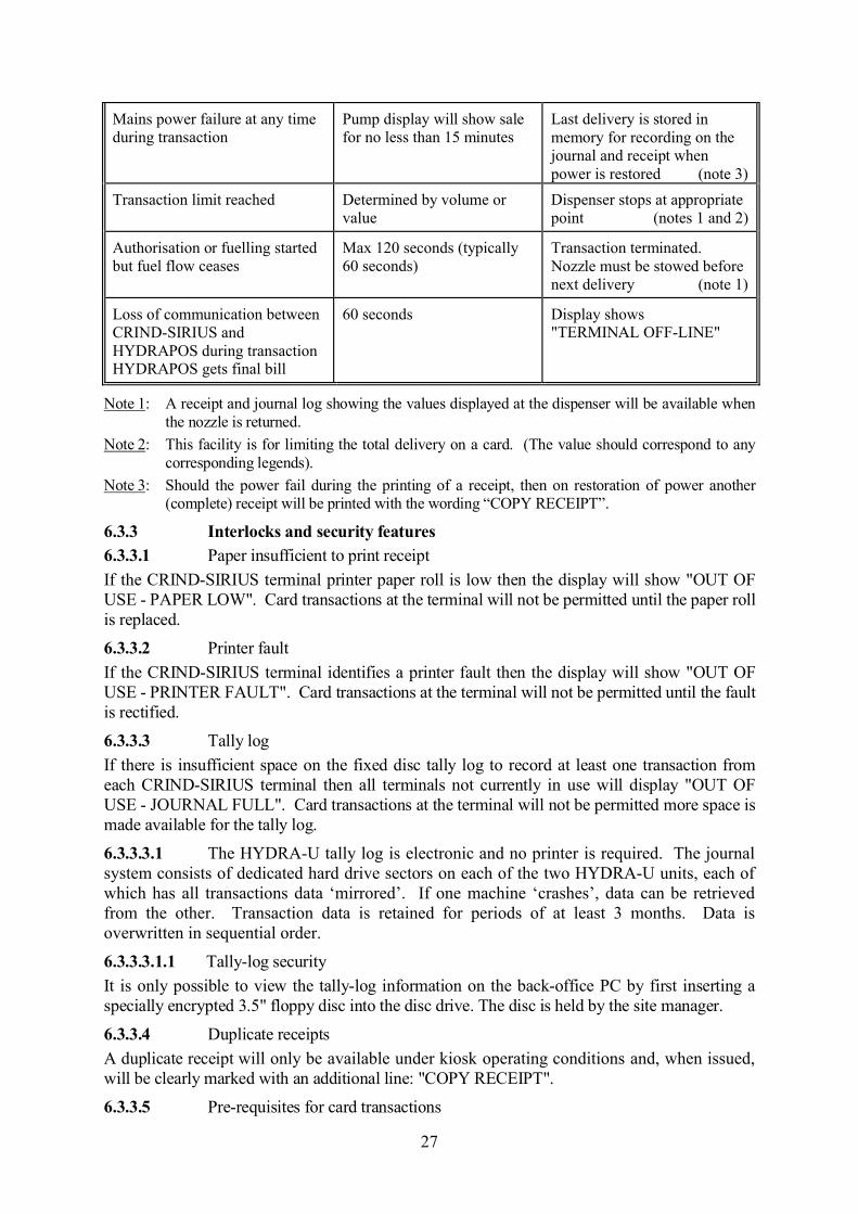
Time-outs and cut-offs
DESCRIPTION RANGE ACTION
Display shows TAKE FUEL but nozzle not removed
1 - 120 seconds Cancel transactionReceipt available
PAY INSIDE selected but nozzle not removed
1 - 120 seconds The display reverts to the initial message
Time-out once refuelling starts (petrol)
Typically 3 minutes Dispenser locked for 5 seconds(note 1)
27
Mains power failure at any time during transaction
Pump display will show sale for no less than 15 minutes
Last delivery is stored in memory for recording on the journal and receipt when power is restored (note 3)
Transaction limit reached Determined by volume or value
Dispenser stops at appropriate point (notes 1 and 2)
Authorisation or fuelling started but fuel flow ceases
Max 120 seconds (typically 60 seconds)
Transaction terminated. Nozzle must be stowed before next delivery (note 1)
Loss of communication between CRIND-SIRIUS and HYDRAPOS during transactionHYDRAPOS gets final bill
60 seconds Display shows "TERMINAL OFF-LINE"
Note 1: A receipt and journal log showing the values displayed at the dispenser will be available when the nozzle is returned.
Note 2: This facility is for limiting the total delivery on a card. (The value should correspond to any corresponding legends).
Note 3: Should the power fail during the printing of a receipt, then on restoration of power another (complete) receipt will be printed with the wording “COPY RECEIPT”.
6.3.3 Interlocks and security features6.3.3.1 Paper insufficient to print receipt
If the CRIND-SIRIUS terminal printer paper roll is low then the display will show "OUT OF USE - PAPER LOW". Card transactions at the terminal will not be permitted until the paper roll is replaced.
6.3.3.2 Printer fault
If the CRIND-SIRIUS terminal identifies a printer fault then the display will show "OUT OF USE - PRINTER FAULT". Card transactions at the terminal will not be permitted until the fault is rectified.
6.3.3.3 Tally log
If there is insufficient space on the fixed disc tally log to record at least one transaction from each CRIND-SIRIUS terminal then all terminals not currently in use will display "OUT OF USE - JOURNAL FULL". Card transactions at the terminal will not be permitted more space is made available for the tally log.
6.3.3.3.1 The HYDRA-U tally log is electronic and no printer is required. The journal system consists of dedicated hard drive sectors on each of the two HYDRA-U units, each of which has all transactions data ‘mirrored’. If one machine ‘crashes’, data can be retrieved from the other. Transaction data is retained for periods of at least 3 months. Data is overwritten in sequential order.
6.3.3.3.1.1 Tally-log security
It is only possible to view the tally-log information on the back-office PC by first inserting a specially encrypted 3.5" floppy disc into the disc drive. The disc is held by the site manager.
6.3.3.4 Duplicate receipts
A duplicate receipt will only be available under kiosk operating conditions and, when issued, will be clearly marked with an additional line: "COPY RECEIPT".
6.3.3.5 Pre-requisites for card transactions
28
Transaction for payment via the CRIND-SIRIUS terminal will only be permitted if:
The purchaser's card is validThe card is not currently in use at another terminalThe card has not reached its daily limit of transaction valueThe dispenser must not have a an unpaid sale or prepayment stored against it
6.3.3.6 Pre-payment
If PRE_PAY is enabled on the site and the option to pay at the HYDRAPOS console is configured at a dispenser then accepting a pre-payment for a dispenser will cause the associated CRIND-SIRIUS terminal to display "IN USE TO PAY INSIDE". The kiosk use condition will be maintained until the pre-paid transaction has been completed via the HYDRAPOS console and the dispenser is idle with no outstanding sales.
6.4 AUTHORISED ALTERNATIVES
6.4.1 CRIND-SIRIUS terminal6.4.1.1 Alternative customer’s card configurations
The following additional steps may be implemented for the validation phase of the operational sequence:
(i) Having a two-card system where an additional customer’s card has to be inserted before fuelling may commence.
(ii) Having a requirement for a PIN number, vehicle or driver's identification, mileage or vehicle registration details.
Such additional steps are, when implemented and configured for use, prompted at the purchaser's display.
6.4.1.2 Card payment only
Having the CRIND-SIRIUS terminal dedicated to card payment only so that the dispenser can only be authorised by use of a valid card, in which case the option to pay at the kiosk by pressing the "NO" button is disabled.
6.4.1.3 Single-sided variant
Having a single-sided version in the same enclosure as the normal double-sided terminal but with a plain steel rear cover.
6.4.1.4 HTEC siriusCRIND 2 (Figures 51 & 52)
As described but having a revised internal design and construction designated HTEC Sirius CRIND 2 – part number *950-00222-100*
6.4.2 The outdoor payment terminal may be Gilbarco CRIND or the Wayne ICR.
6.4.3 Any UPS conforming to the following:- A UPS capable of supplying 500 VA or greater for up to 20 minutes.- CE marked for safety and for EMC emissions/immunity.- Having the capability to signal to HYDRA-U that the mains input has failed.- Capable of being set or adjusted for a trigger point of 186V AC (minimum
allowable supply voltage less 10%)6.4.4 The following alternative operation may be implemented for card verification. Such additional steps are prompted at the purchaser’s display.
- Having a two-card system where an additional customer’s card has to be inserted before fuelling may commence.
- Having a requirement for a PIN number, vehicle or driver’s identification, mileage or vehicle registration details.
6.4.5 HTEC loyalty server
29
Where a loyalty scheme is required, an HTEC CRIND-GALAXY unit connected via the Opto-Isolator Unit may optionally be fitted. The CRIND-GALAXY unit calculates the loyalty points. It is similar to the standard GALAXY loyalty terminal but omits the magnetic card reader mechanism as the loyalty card is read by the card reader in the OPT equipment.
6.4.6 Up-dated outdoor payment terminal (HTEC siriusCRIND 2)
As described in the certificate and having revised internal design and construction. Manufacturer’s designation is ‘HTEC siriusCRIND 2’. Part number is:- *950-00222-100*. External dimensions, functionality, and electrical connections are identical. The screen is an illuminated dot matrix type, but external appearance is otherwise similar, see Figures 6 and 7. This equipment may be fitted on new sites, or may optionally be fitted as a replacement for the earlier version. Test requirements are unchanged. A typical receipt ticket is shown in Figure 8.
6.4.7 Optional alternative PC (Dell Optiplex DHM)
An optional alternative PC based KCU/ display system for use in unmanned forecourts. Views of the Optiplex PC are shown in Figure 9. The PC system is the Optiplex GX DHM.
Operating system may be MS Windows 98, MS Windows NT, or MS Windows 2000.
Any suitable CE marked monitor screen, keyboard assembly, or ‘mouse’ may be used.
Software version number is remains as described in the certification.
The system as described in the certificate utilises a ‘Moxa’ PC plug-in assembly which couples the dispenser control signals via an external ‘opto-isolator’ interface unit. The alternative arrangement dispenses with use of the PC plug-in unit and combines the functions previously performed by both the plug-in assembly and the interface unit into the Site Controller assemblies referred to below. In each case, connection(s) to the KCU/POS PC are via USB termination.
6.4.8 HTEC siriusCRIND 2 – outdoor payment terminal – ‘chip and pin’ card-reader option.
As described in the certificate but having optionally fitted, ‘chip and pin’ card-reader modules.
6.4.8.1 Units with the new card-reader fitted may be installed in all sites, both manned and unmanned. Bank requirements may restrict the payment limit and will not allow transactions to proceed if a fault is detected which may prevent the issue of a printed receipt. If the transaction cannot proceed, a warning message is displayed requesting the customer to use an alternative dispenser. A general view and receipt format are shown in Figure 10. In use, merchant data will include site name and address.
30
6.5 HydraOPT II Option (Figure 61)
Having the HydraOPT II installed, replacing the Sirius CRIND as described above.
6.5.1 Construction
6.5.1.1 .EZ0083 Unified PIN & Card (UPC) Module.
This is the PIN pad section of the terminal, which contains the following circuit boards, and a card reader mechanism:
o EB0024-8 (secure processor board)
o EB0025-1 (keypad board)
o EB0026-0 (security fence)
o EB0028-1 (security wrap)
o EO0013 = Card Reader Mechanism, Sankyo model ICM330-3R0510S
6.5.1.2 EZ0097-5A Secure Display Controller (SDC) Module.
This is the display section of the terminal, which also controls message routing to other functional blocks.It contains a board, and the LCD which is a module FTL specified and buys as a single part:
o EB0036-5A (secure display controller board)
o EZ0085 = LCD Module, comprising
1. LCD, Innolux model A050-22-TT-11
2. Toughened, AR-coated glass lens
6.5.1.3 EZ0084 Printer/Power Supply Module.
This contains the low-voltage switching supplies used to power the other functional blocks of the terminal, the printer controller and all the external interface connectors.It comprises a single board, and an OEM printer mechanism:
o EB0034-8 (printer controller/power supply board)
o EO0015 = Printer Mechanism, Fujitsu model FTP-628MCL401-RA
6.5.1.4 EZ0116-2 Contactless Module.
This module contains the radio interface and antenna required to communicate with contactless chip cards.It also contains connectors for the optional barcode reader.
o EB0062-2 (contactless interface board)o EB0035-7 (contactless antenna)o EO0019 = Barcode Reader, Icomis model CSE-6000)
7 RECOMMENDED TESTSThe following tests may be carried out in addition to those specified in the Regulations and in the dispenser certification to assist in determining conformity with the approval pattern.
7.1 Verify that for each transaction, there is no discrepancy between the pump indication and the printed receipt values with regard to price and volume.
7.2 Verify that the sequence of operation is generally as described in the tables of Sections: 3.2 & 6.3.2.1.1.
7.3 Check that a receipt is available from the payment terminals on completion of delivery.
31
7.4 Check that for all transactions, the volume and price indicated on the dispenser display correspond to those shown on receipts and recorded on the journal display.
7.5 Verify that software issue is as described in Section 3.6.
8 CERTIFICATE HISTORY
ISSUE NO. DATE DESCRIPTION
Series: S038 15 May 2012 Certificate first issued as a supplement.
Series: S038 Revision 1 27 June 2012 Section 4.3, - deletion of the following text “part number 950-00210-100” in indent 1)& “part number 950-00214-100” inindent 2)
Addition and renumbering of sections
Addition of Figures 51 -60
Series: S038 Revision 2 24 May 2013 Addition of section 6.5 HydraOPT II
Renumbering of subsequent sections
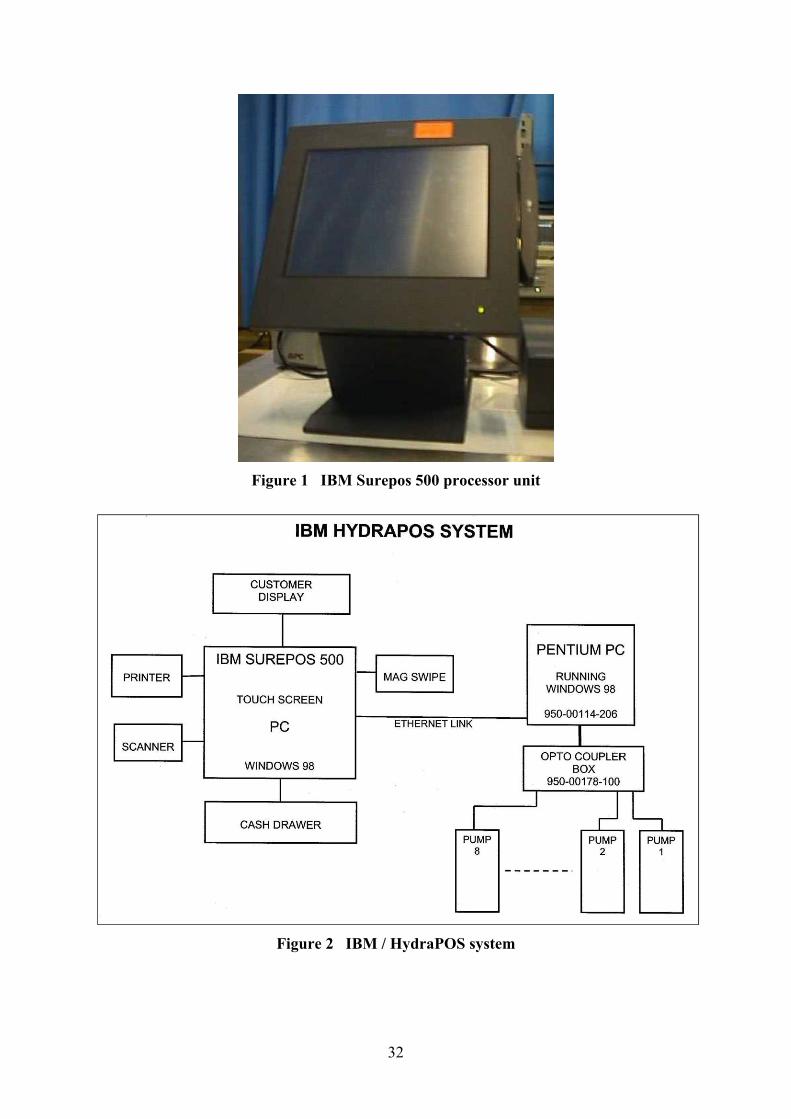
32
Figure 1 IBM Surepos 500 processor unit
Figure 2 IBM / HydraPOS system
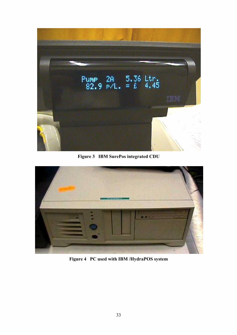
Figure 3 IBM SurePos i
Figure 4
33
Figure 3 IBM SurePos integrated CDU
Figure 4 PC used with IBM /HydraPOS system
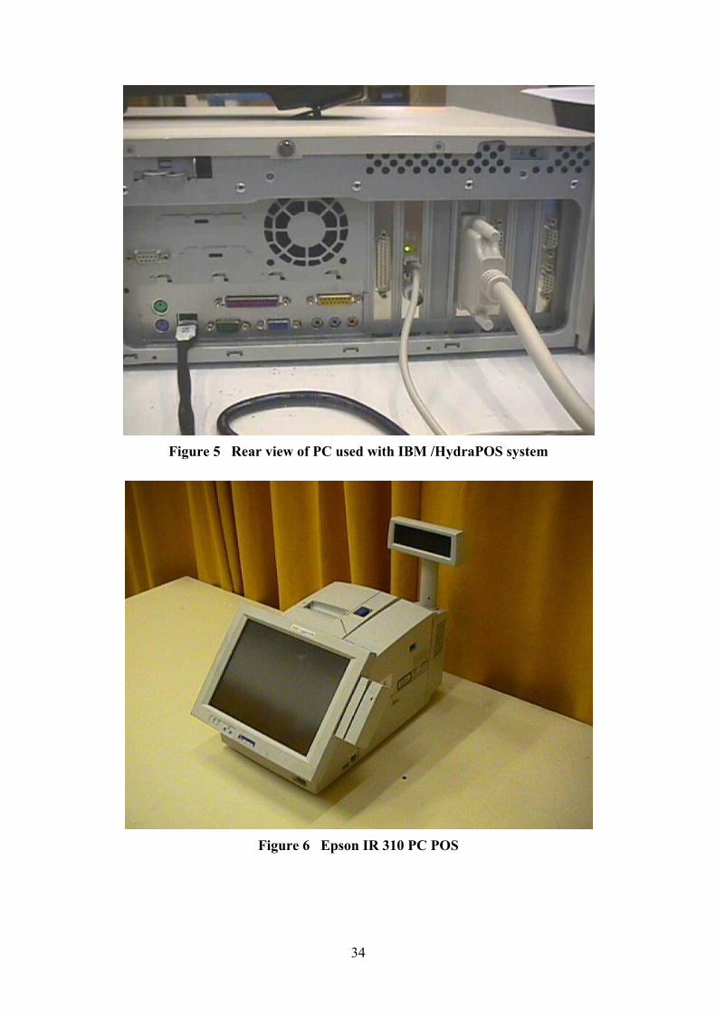
34
Figure 5 Rear view of PC used with IBM /HydraPOS system
Figure 6 Epson IR 310 PC POS
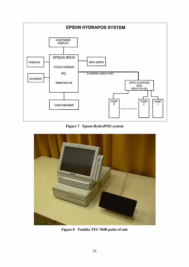
35
Figure 7 Epson HydraPOS system
Figure 8 Toshiba TEC 5600 point of sale
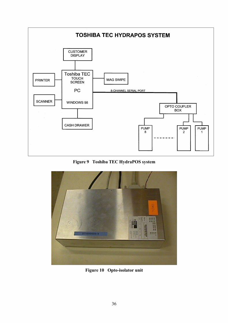
36
Figure 9 Toshiba TEC HydraPOS system
Figure 10 Opto-isolator unit
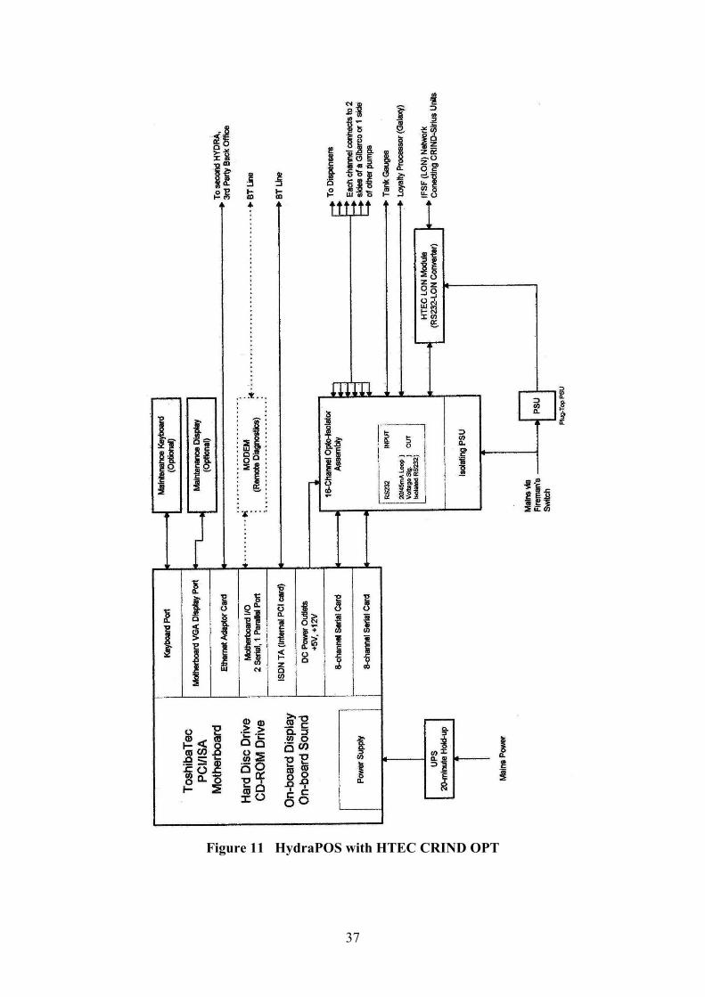
37
Figure 11 HydraPOS with HTEC CRIND OPT
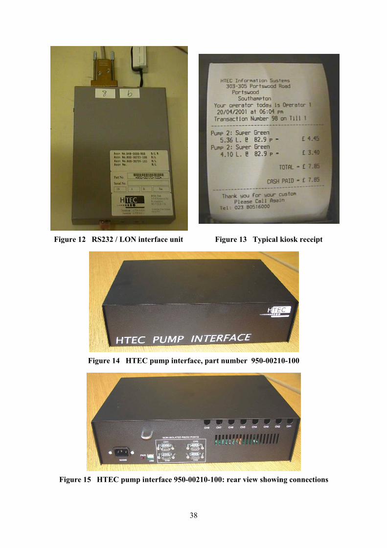
Figure 12 RS232 / LON interface unit
Figure 14 HTEC
Figure 15 HTEC pump i
38
Figure 12 RS232 / LON interface unit Figure 13 Typical kiosk receipt
HTEC pump interface, part number 950-00210
pump interface 950-00210-100: rear view showing connections
Figure 13 Typical kiosk receipt
00210-100
: rear view showing connections
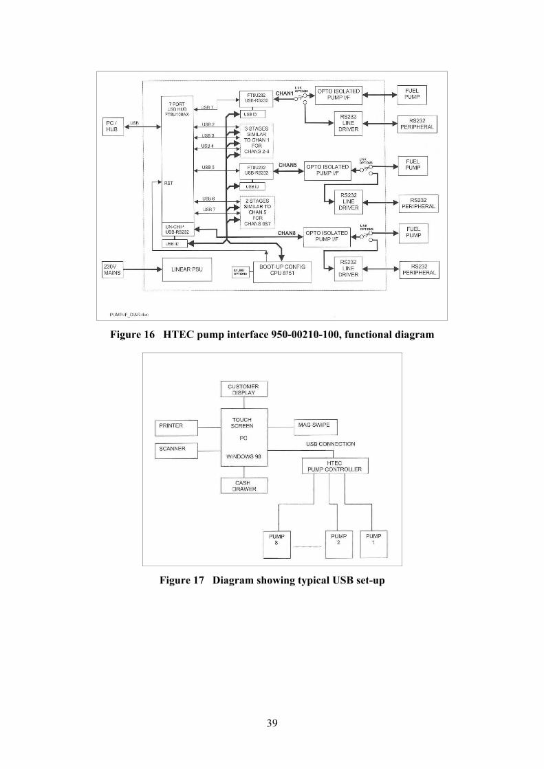
39
Figure 16 HTEC pump interface 950-00210-100, functional diagram
Figure 17 Diagram showing typical USB set-up
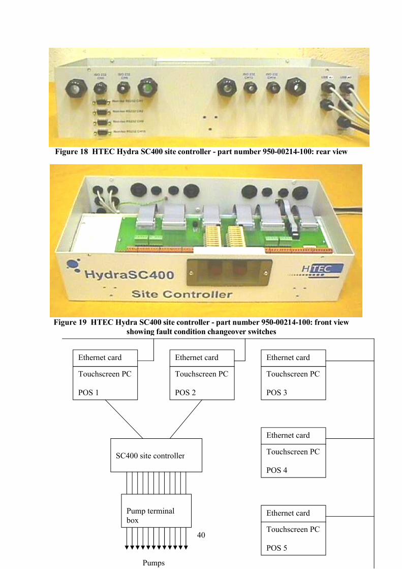
Figure 18 HTEC Hydra SC400
Figure 19 HTEC Hydra SC400 showing fault
Touchscreen PC
POS 1
Ethernet card
SC400 site controller
Pump terminal box
Pumps
40
HTEC Hydra SC400 site controller - part number 950-00214
HTEC Hydra SC400 site controller - part number 950-00214showing fault condition changeover switches
Touchscreen PC
POS 2
Touchscreen PC
POS 3
Touchscreen PC
POS 4
Touchscreen PC
POS 5
Ethernet card Ethernet card
Ethernet
Ethernet card
SC400 site controller
Pump terminal
Pumps
00214-100: rear view
00214-100: front view
Touchscreen PC
Touchscreen PC
Touchscreen PC
Ethernet card
Ethernet card
Ethernet card
41
Figure 20 HTEC Hydra SC400 site controller: typical set-up
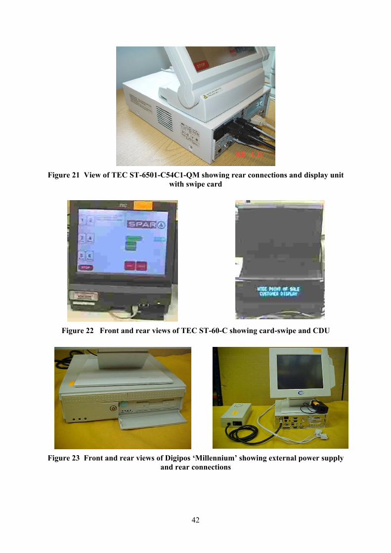
Figure 21 View of TEC ST-
Figure 22 Front and rear views of TEC ST
Figure 23 Front and rear views of Digipos
42
-6501-C54C1-QM showing rear connections andwith swipe card
ront and rear views of TEC ST-60-C showing card-swipe and CDU
ront and rear views of Digipos ‘Millennium’ showing external power supply and rear connections
QM showing rear connections and display unit
swipe and CDU
showing external power supply
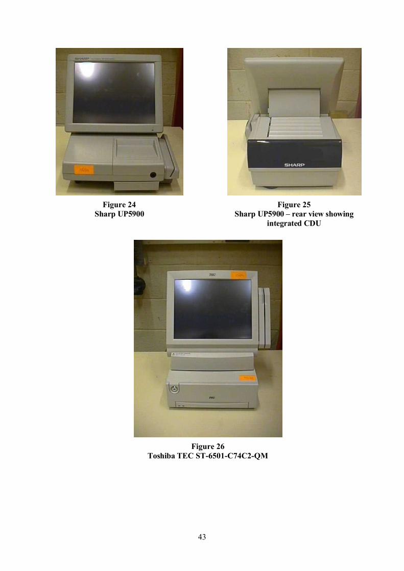
43
Figure 24Sharp UP5900
Figure 25Sharp UP5900 – rear view showing
integrated CDU
Figure 26Toshiba TEC ST-6501-C74C2-QM
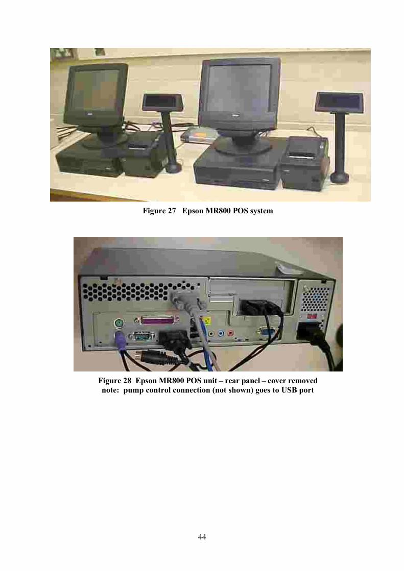
44
Figure 27 Epson MR800 POS system
Figure 28 Epson MR800 POS unit – rear panel – cover removednote: pump control connection (not shown) goes to USB port
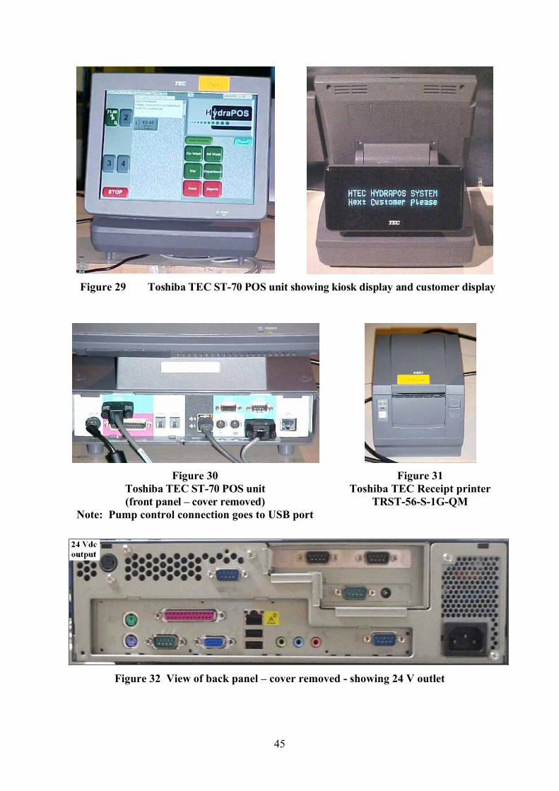
45
Figure 29 Toshiba TEC ST-70 POS unit showing kiosk display and customer display
Figure 30Toshiba TEC ST-70 POS unit(front panel – cover removed)
Note: Pump control connection goes to USB port
Figure 31 Toshiba TEC Receipt printer
TRST-56-S-1G-QM
Figure 32 View of back panel – cover removed - showing 24 V outlet
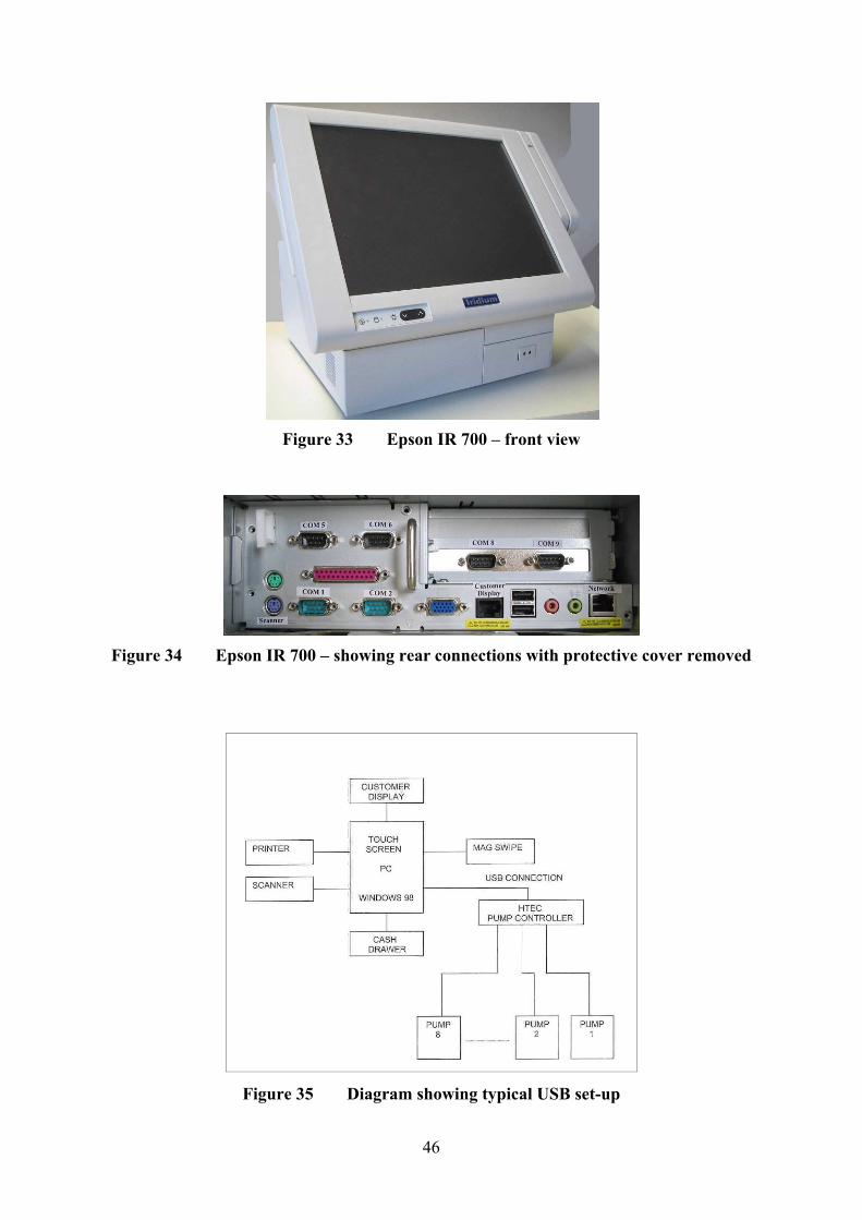
46
Figure 33 Epson IR 700 – front view
Figure 34 Epson IR 700 – showing rear connections with protective cover removed
Figure 35 Diagram showing typical USB set-up
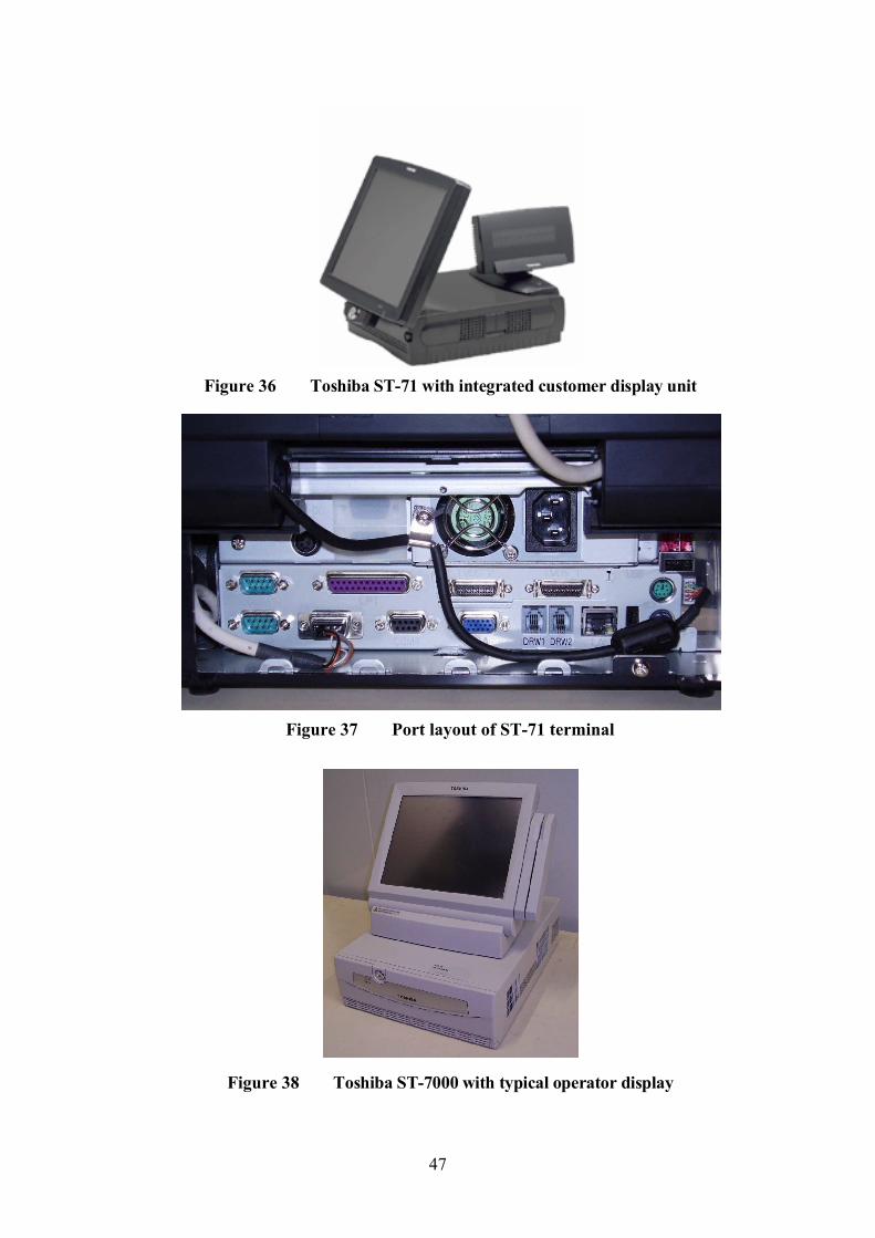
47
Figure 36 Toshiba ST-71 with integrated customer display unit
Figure 37 Port layout of ST-71 terminal
Figure 38 Toshiba ST-7000 with typical operator display
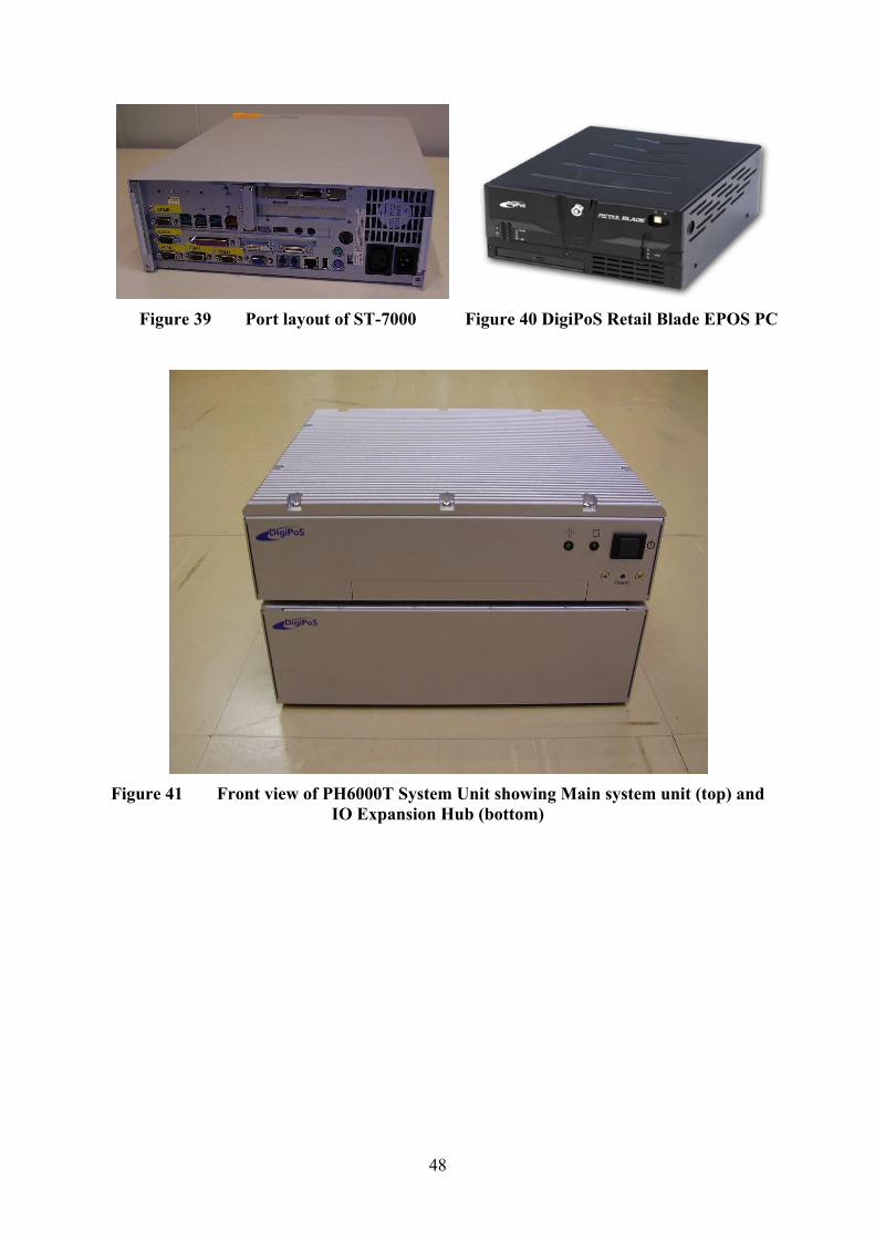
48
Figure 39 Port layout of ST-7000 Figure 40 DigiPoS Retail Blade EPOS PC
Figure 41 Front view of PH6000T System Unit showing Main system unit (top) and IO Expansion Hub (bottom)
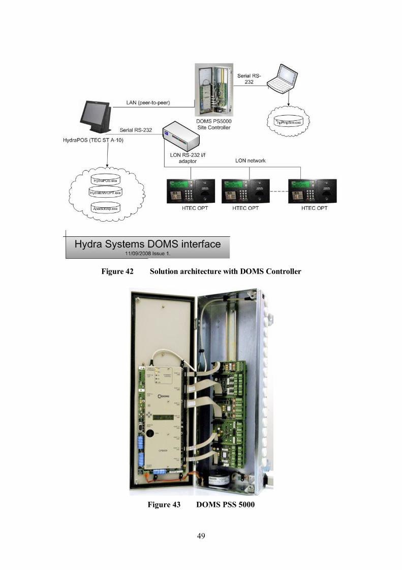
49
Figure 42 Solution architecture with DOMS Controller
Figure 43 DOMS PSS 5000
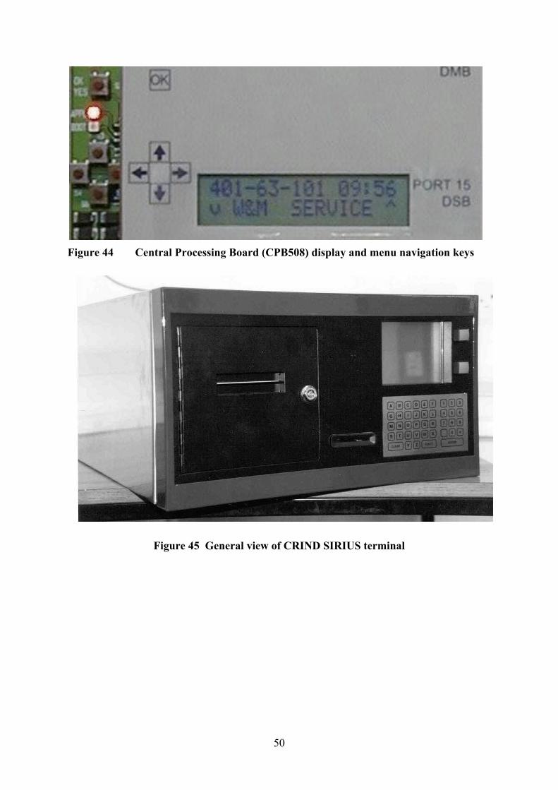
50
Figure 44 Central Processing Board (CPB508) display and menu navigation keys
Figure 45 General view of CRIND SIRIUS terminal
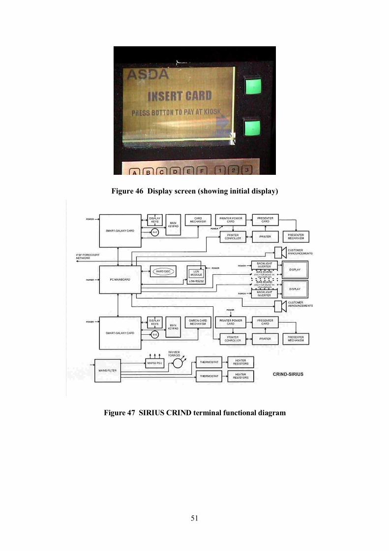
51
Figure 46 Display screen (showing initial display)
Figure 47 SIRIUS CRIND terminal functional diagram
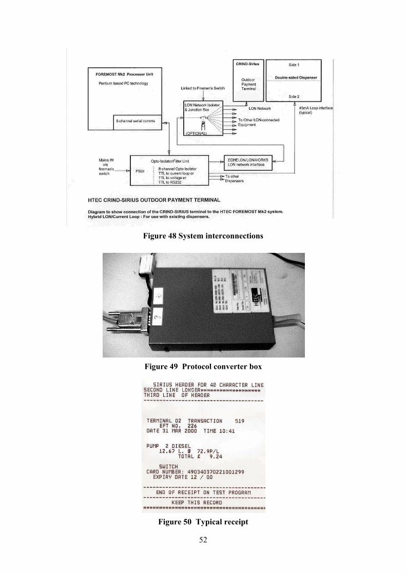
52
Figure 48 System interconnections
Figure 49 Protocol converter box
Figure 50 Typical receipt
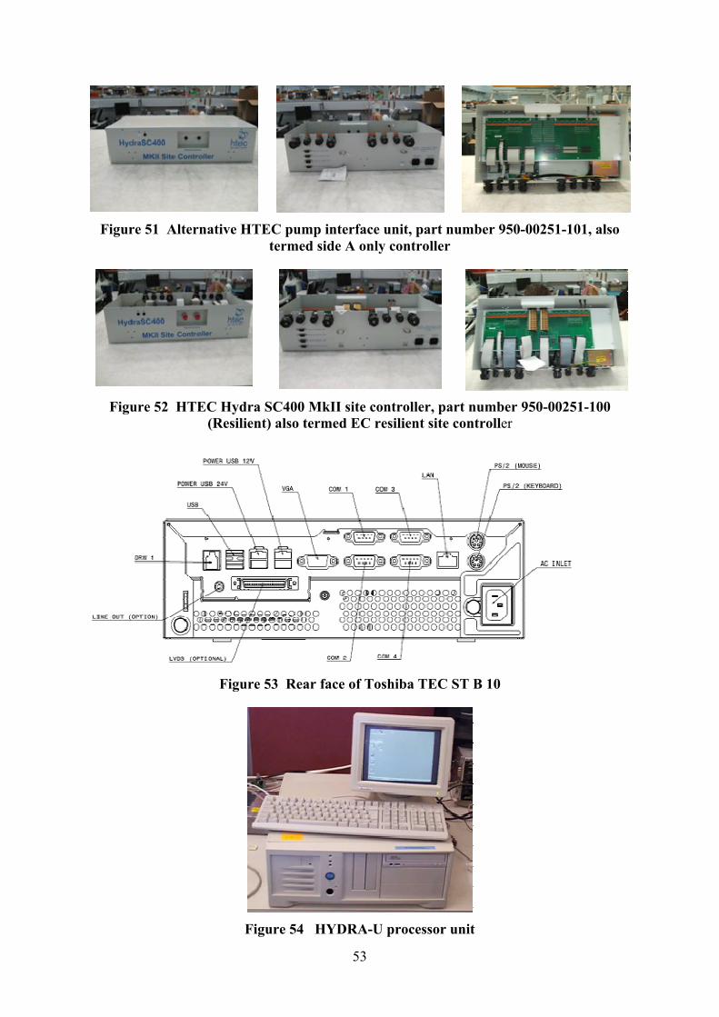
Figure 51 Alternative HTEC pump interface unit, part number 950
Figure 52 HTEC Hydra SC400 MkII site controller, part number 950(Resilient) also termed EC
Figure 53 Rear face of Toshiba T
Figure 54 HYDRA
53
Figure 51 Alternative HTEC pump interface unit, part number 950termed side A only controller
Figure 52 HTEC Hydra SC400 MkII site controller, part number 950(Resilient) also termed EC resilient site controller
Figure 53 Rear face of Toshiba TEC ST B 10
Figure 54 HYDRA-U processor unit
Figure 51 Alternative HTEC pump interface unit, part number 950-00251-101, also
Figure 52 HTEC Hydra SC400 MkII site controller, part number 950-00251-100
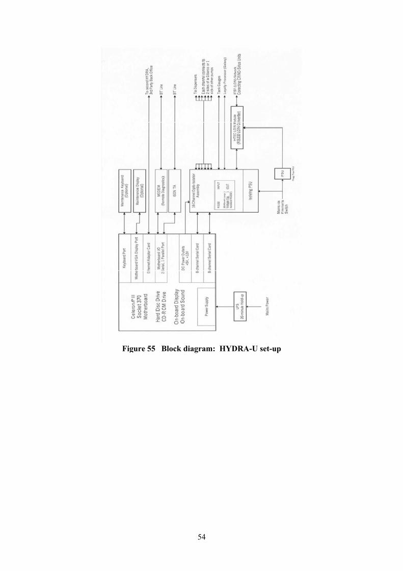
Figure 55
54
Figure 55 Block diagram: HYDRA-U set-up
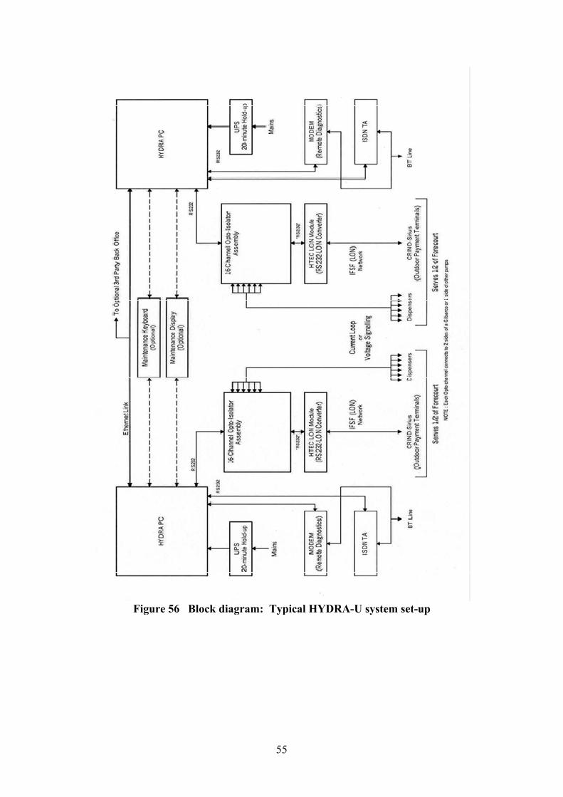
Figure 56 Block diagram: Typical
55
Figure 56 Block diagram: Typical HYDRA-U system setU system set-up
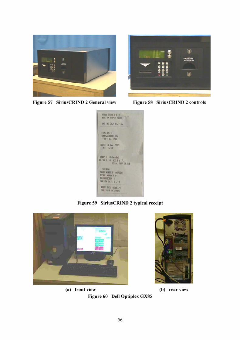
Figure 57 SiriusCRIND 2 General view
Figure 59 SiriusCRIND 2 typical receipt
(a) front view
56
Figure 57 SiriusCRIND 2 General view Figure 58 SiriusCRIND 2 controls
Figure 59 SiriusCRIND 2 typical receipt
(a) front view (b) rear view
Figure 60 Dell Optiplex GX85
Figure 58 SiriusCRIND 2 controls
(b) rear view
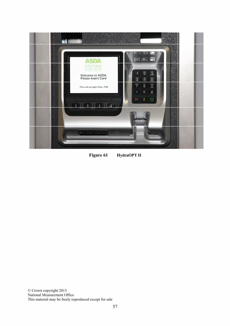
© Crown copyright 2013National Measurement OfficeThis material may be freely reproduced except for saleThis material may be freely reproduced except for sale
57
Figure 61 HydraOPT II