Embed Size (px)
Citation preview
Series R™Helical RotaryLiquid Chillers
RLC-PRC023-E4
Model RTHD
Water cooled
500-1500 kW
2 RLC-PRC023-E4
Introduction
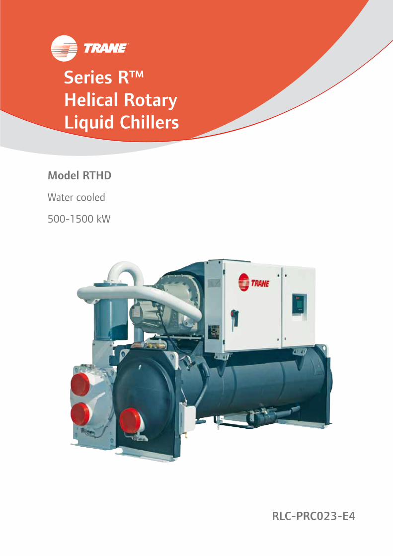
Trane offers water-cooled helical rotary compressor chillers, the model RTHD.
The industrial-grade design of this Series RTM helical rotary chiller is ideal for both industrial and commercial markets, in applications such as office buildings, hospitals, schools, retail buildings, and industrial facilities.
The model RTHD features:
• High energy efficiency
• High reliability
• Bolt together construction
• R134a refrigerant
• “Adaptive ControlTM”
• CH.530 controls enable:
- Scrolling access to inputs and operating information via the LCD touch-screen display
- Freedom from interoperability concerns with LonMark® communications
- Job-specific communication options that allow greater reporting flexibility
• Improved startup temperature capabilities and reduced sensitivity to condenser water temperatures alleviate the most common startup concerns
• Removed Liquid Vapor Separator, providing lighter unit weight and simplified refrigerant piping, for less expensive handling, separation, and installation
With its extensive compressor development and manufacturing experience, Trane designs and build chillers with a higher efficiency and reliability than the units available on today’s market.
The linear unloading compressor, wide operating temperature range, advanced controls, electronic expansion valve, short anti-recycle timers, and industry-leading efficiencies mean that this Trane Series R chiller is the perfect choice for tight temperature control in almost any application temperatures, and under widely varying loads.
RLC-PRC023-E4 3
Contents
Introduction 2
Features and Benefits 4
Application Considerations 6
Selection Procedure 9
General Data 12
Electrical Data and Connections 14
Dimensions and Weights 15
Mechanical Specifications 22
4 RLC-PRC023-E4
Features and Benefits
Application Versatility and High Performance• Screw compressor technology
and the electronic expansion valve provide reliable performance in an expanded range of operating temperatures.
• Tight water temperature control extends to operation of multiple chillers in parallel or series configurations, offering further system design flexibility for maximum efficiency.
• Advanced design enables chilled water temperature control to +/- 0.28°C for flow changes up to 10% per minute, plus handling of flow changes up to 30% per minute for comfort cooling.
• Two-minute stop-to-start and five-minute start-to-start anti-recycle timer allows tight chilled water temperature control in constant or transient low-load applications.
• LonMark communications capability provides excellent, trouble-free interoperability.
• Generic Building Automation System points are available for easy access to operational information.
Industrial/Low Temperature Process Cooling
Excellent operating temperature range and precise control capabilities enable tight control with single chiller or series configuration.
Ice/Thermal Storage - Specifiers and operators benefit from dual setpoint control and industry-leading temperature, efficiency, and control capabilities, that minimize design time and energy costs.
Simple, Economical Installation• Compact size makes the model
RTHD well suited for the retrofit and replacement market.
• All units fit through standard double-width doors.
• Bolt-together construction makes for fast, easy unit disassembly.
• Small RTHD footprint saves valuable equipment room space and alleviates access concerns for most retrofit jobs.
• Light weight design simplifies rigging requirements, further reducing installation time requirements and costs.
• Full factory refrigerant or nitrogen and oil charges reduce required field labor, materials, and installation cost.
• Only evaporator and condenser water piping is required; no starter water cooling (with its associated safety concerns) or field piping is necessary.
• Oil cooler and purge system connections have been eliminated.
• Simple power connection simplifies overall installation.
• Standard unit-mounted starter for Star-Delta and Solid State eliminates additional job site installation considerations and labor requirements.
• Trane has conducted extensive factory testing, and also offers options for in-person and/or documented system performance verification.
• CH.530 controls easily interface with Tracer Summit™ building automation systems through single twisted-pair wire.
RLC-PRC023-E4 5
Features and Benefits
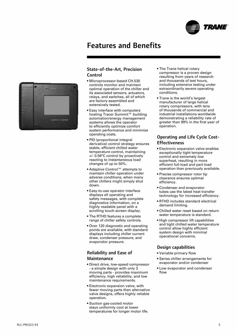
State-of-the-Art, Precision Control• Microprocessor-based CH.530
controls monitor and maintain optimal operation of the chiller and its associated sensors, actuators, relays, and switches, all of which are factory-assembled and extensively tested.
• Easy interface with computers hosting Tracer Summit™ building automation/energy management systems allows the operator to efficiently optimize comfort system performance and minimize operating costs.
• PID (proportional integral derivative) control strategy ensures stable, efficient chilled water temperature control, maintaining +/- 0.56°C control by proactively reacting to instantaneous load changes of up to 50%.
• Adaptive Control™ attempts to maintain chiller operation under adverse conditions, when many other chillers might simply shut down.
• Easy-to-use operator interface displays all operating and safety messages, with complete diagnostics information, on a highly readable panel with a scrolling touch-screen display.
• The RTHD features a complete range of chiller safety controls.
• Over 120 diagnostic and operating points are available, with standard displays including chiller current draw, condenser pressure, and evaporator pressure.
Reliability and Ease of Maintenance • Direct drive, low-speed compressor
- a simple design with only 3 moving parts - provides maximum efficiency, high reliability, and low maintenance requirements.
• Electronic expansion valve, with fewer moving parts than alternative valve designs, offers highly reliable operation.
• Suction gas-cooled motor stays uniformly cool at lower temperatures for longer motor life.
• The Trane helical rotary compressor is a proven design resulting from years of research and thousands of test hours, including extensive testing under extraordinarily severe operating conditions.
• Trane is the world’s largest manufacturer of large helical rotary compressors, with tens of thousands of commercial and industrial installations worldwide demonstrating a reliability rate of greater than 99% in the first year of operation.
Operating and Life Cycle Cost-Effectiveness• Electronic expansion valve enables
exceptionally tight temperature control and extremely low superheat, resulting in more efficient full-load and part-load operation than previously available.
• Precise compressor rotor tip clearance ensures optimal efficiency.
• Condenser and evaporator tubes use the latest heat transfer technology for increased efficiency.
• RTHD includes standard electrical demand limiting.
• Chilled water reset based on return water temperature is standard.
• High compressor lift capabilities and tight chilled water temperature control allow highly efficient system design with minimal operational concerns.
Design capabilities• Variable primary flow
• Series chiller arrangements for evaporator and/or condenser
• Low evaporator and condenser flow
6 RLC-PRC023-E4
Application Considerations
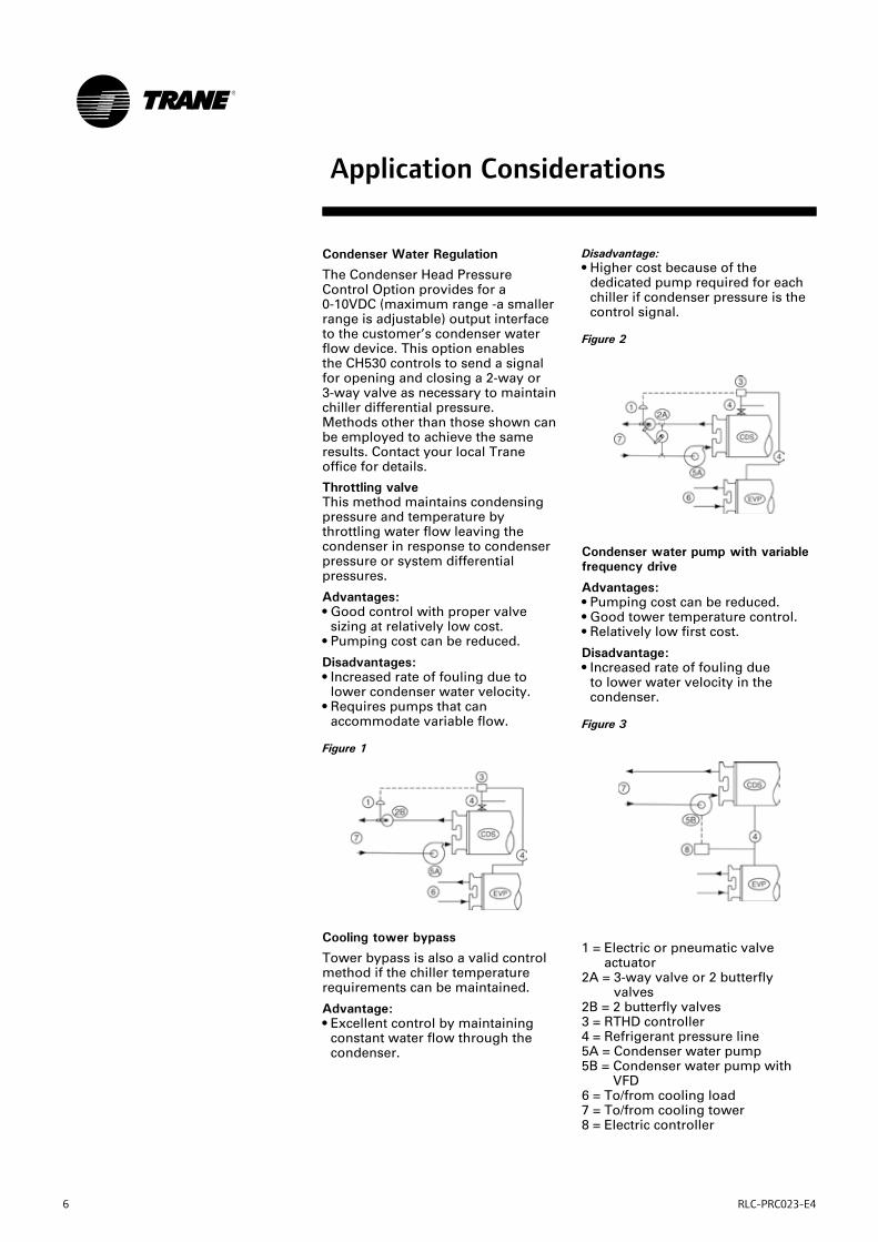
Condenser Water Regulation
The Condenser Head Pressure Control Option provides for a 0-10VDC (maximum range -a smaller range is adjustable) output interface to the customer’s condenser water flow device. This option enables the CH530 controls to send a signal for opening and closing a 2-way or 3-way valve as necessary to maintain chiller differential pressure.Methods other than those shown can be employed to achieve the same results. Contact your local Trane office for details.
Throttling valve This method maintains condensing pressure and temperature by throttling water flow leaving the condenser in response to condenser pressure or system differential pressures.
Advantages:• Good control with proper valve
sizing at relatively low cost.• Pumping cost can be reduced.
Disadvantages:• Increased rate of fouling due to
lower condenser water velocity.• Requires pumps that can
accommodate variable flow.
Figure 1
Disadvantage:• Higher cost because of the
dedicated pump required for each chiller if condenser pressure is the control signal.
Figure 2
Cooling tower bypass
Tower bypass is also a valid control method if the chiller temperature requirements can be maintained.
Advantage:• Excellent control by maintaining
constant water flow through the condenser.
1 = Electric or pneumatic valve actuator
2A = 3-way valve or 2 butterfly valves
2B = 2 butterfly valves3 = RTHD controller4 = Refrigerant pressure line5A = Condenser water pump5B = Condenser water pump with
VFD6 = To/from cooling load7 = To/from cooling tower8 = Electric controller
Condenser water pump with variable frequency drive
Advantages:• Pumping cost can be reduced. • Good tower temperature control.• Relatively low first cost.
Disadvantage:• Increased rate of fouling due
to lower water velocity in the condenser.
Figure 3
RLC-PRC023-E4 7
Application Considerations
Variable Evaporator Flow and Short Evaporator Water Loops
Variable evaporator flow is an energy-saving design strategy which has quickly gained acceptance as advances in chiller and controls technology have made it possible. With its linear unloading compressor design and advanced CH.530 controls, the RTHD has excellent capability to maintain leaving water temperature control within +/- 0.28°C, even for systems with variable evaporator flow and small chilled water volumes.Some basic rules should be followed whenever using these system design and operational savings methods with the RTHD. The proper location of the chilled water temperature control sensor is in the supply (outlet) water. This location allows the building to act as a buffer, and it assures a slowly changing return water temperature. If there is insufficient water volume in the system to provide an adequate buffer, temperature control can be lost, resulting in erratic system operation and excessive compressor cycling. To ensure consistent operation and tight temperature control, the chilled water loop should be at least 2 minutes. If this recommendation cannot be followed, and tight leaving water temperature control is necessary, a storage tank or larger header pipe should be installed to increase the volume of water in the system.For variable primary flow applications, the rate of chilled water flow change should not exceed 10% of design per minute to maintain +/- 0.28°C leaving evaporator temperature control.For applications in which system energy savings is most important and tight temperature control is classified as +/-1.1°C, up to 30% changes in flow per minute are possible. Flow rates should be maintained between the minimum and maximum allowed for any particular chiller configuration.
Series Chiller Arrangements
Another energy-saving strategy is to design the system around chillers arranged in series, on the evaporator, condenser, or both. The actual savings possible with such strategies depends on the application dynamics and should be researched by consulting your Trane Systems Solutions Representative and applying the Trane System Analyzer program. It is possible to operate a pair of chillers more efficiently in a series chiller arrangement than in a parallel arrangement. It is also possible to achieve higher entering-to-leaving chiller differentials, which may, in turn, provide the opportunity for lower chilled water design temperature, lower design flow, and resulting installation and operational cost savings. The Trane screw compressor also has excellent capabilities for «lift», which affords an opportunity for savings on the evaporator and condenser water loops.Like series arrangements on the evaporator, series arrangements on the condenser may enable savings. This approach may allow reductions in pump and tower installation and operating costs. Maximizing system efficiency requires that the designer balance performance considerations for all system components; the best approach may or may not involve multiple chillers, or series arrangement of the evaporators and/or condensers. This ideal balance of design integrity with installation and operating cost considerations can also be obtained by consulting a Trane representative and applying the Trane System Analyzer program.
Water Treatment
The use of untreated or improperly treated water in chillers may result in scaling, erosion, corrosion, and algae or slime buildup. It is recommended that the services of a qualified water treatment specialist be engaged to determine what treatment, if any, is advisable. Trane assumes no responsibility for the results of using untreated or improperly treated water.
8 RLC-PRC023-E4
Water Pumps
Where noise limitation and vibration-free operation are important, Trane strongly encourages the use of 1450-rpm (50 Hz) pumps. Specifying or using 3000-rpm (50 Hz) condenser water and chilled water pumps must be avoided, because such pumps may operate with objectionable levels of noise and vibration. In addition, a low frequency beat may occur due to the slight difference in operating rpm between 3000-rpm (50 Hz) water pumps and Series R chiller motors.
Important Note: The chilled water pump must not be used to stop the chiller.
Acoustic Considerations
Refer to the Engineering Bulletin RLC-PRB006 regarding Sound Data/Installation Guide for Noise-Sensitive Applications for Trane water-cooled helical-rotary chillers. Using the information provided in this bulletin, contact a certified sound consultant to aid in proper mechanical room design and treatment
Sound data given data in accordance with ISO 3746-1996.
Application Considerations
RLC-PRC023-E4 9
Selection Procedure
Chiller selections and performance information can be obtained through the use of the Series R® Chiller selection program.
Performance
The computer selection program provides performance data for each chiller selection.
Dimensional Drawings
The dimensional drawings illustrate overall measurements of the unit. Also shown are the service clearances required to easily service the RTHD chiller. All catalog dimensional drawings are subject to change. Current submittal drawings should be referred to for detailed dimensional information. Contact the sales office for submittal information.
Electrical Data Tables
Compressor motor electrical data is shown in the data section for each compressor size. Rated load amperes (RLA), locked rotor Star-Delta amperes (LRAY), the power factor for standard voltages for all 50 Hz, 3-phase motors are shown. The RLA is based on the performance of the motor developing full rated horsepower. A voltage utilization range is tabulated for each voltage listed.
Evaporator and Condenser Pressure Drop
Pressure drop data is determined by the RTHD selection program.
10 RLC-PRC023-E4
Selection Procedure
Digit 1-2-3-4-5: Chiller series RTHDE: Epinal RTHD
Digit 6-7: Unit sizeB1-B2-C1-C2-D1-D2-D3-E3
Digit 8: Main power voltageR: 380V/50Hz/3Ph +/-5%T: 400V/50Hz/3Ph +/-10%U: 415V/50Hz3PH +/-5%S: Special
Digit 9: Other special requirementsX: NoS: Yes
Digit 13: Pressure vessel approvalP: PED (Pressure equipment directive)S: Special
Digit 14-15: Evaporator sizeB1-C1-D1-D2-D3-D4-D5-D6-E1-F1-F2-G1-G2-G3
Digit 17: Evaporator water passes 2: 2 passes3: 3 passes4: 4 passes6: 6 passesS: Special
Digit 18: Evaporator water connectionL: Left handR: Right hand
Digit 19: Evaporator connection typeA: VictaulicB: Victaulic + couplingS: Special
Digit 20: Evaporator waterside pressureL: EVP 10 barH: EVP 21 bar
Digit 21-22: Condenser sizeB1-D1-E1-E2-E3-E4-E5-F1-F2-F3-G1-G2-G3
Digit 23: Condenser tube typeA: Enhanced fin - copperB: Smooth bore - copperC: Smooth bore - 90/10 Cu/NiS: Special
Digit 24: Condenser water passes2: 2 passesS: Special
Digit 25: Condenser water connectionL: Left handR: Right hand
Digit 26: Condenser connection typeA: VictaulicB: Victaulic + couplingS: Special
Digit 27: Condenser waterside pressureL: CDS 10 barH: CDS 21 bar
Digit 28: Condenser leaving water temperatureA: Standard T < or = 45°CB: HI 45 < T < or = 50°C
Digit 29: Refrigerant specialtiesX: WithoutG: GaugesV: Isolation valvesB: V+G
Digit 30: Oil coolerX: WithoutC: With
Digit 31: Thermal insulationX: WithoutQ: Cold parts
Digit 33: LanguageC: SpanishD: GermanE: EnglishF: FrenchH: DutchI: ItalianM: SwedishP: PolishT: CzechU: GreekV: PortugueseG: Hungarian
Digit 34: Safety devicesX: StandardB: Dual safety valvesA: B + rupture disc
Digit 35: Refrigerant chargeA: Full factory charge (R134a)B: Nitrogen (No oil)C: Holding charge (R134a)
Digit 36: Shipping packageA: DomesticC: Domestic + skidE: SEI class 3F: SEI class 4aG: SEI class 4cS: Special
Digit 37: Flow switchX: WithoutA: EvaporatorB: Evaporator + condenser.
Digit 38: Factory testA: Functional testB: Customer inspectionC: Witness testD: Performance test with reportS: Special
RLC-PRC023-E4 11
Selection Procedure
Digit 39: Starter typeY: Star-delta closed transition starter
Digit 43: Power line connection typeA: Terminal blockB: Disconnect switch (No fuses)D: Circuit breakerK: Disconnect switch and fuses
Digit 44: Electrical protectionB: StandardD: IP20 electrical protection
Digit 45: Electrical protectionX: StandardU: Under/over voltage protectionG: Ground fault protection relayB: U+G
Digit 46: Unit operator interface (Dynaview)B: FrenchC: ItalianD: SpanishE: GermanF: DutchG: EnglishK: Portuguese
Digit 47: Remote interfaceX: Without4: Tracer COMM 45: Tracer COMM 5 LCI-C (LonTalk)
Digit 48: External chilled water + current limit setpointX: Without4: 4-20mA input2: 2-10Vdc input
Digit 49: External base loadingX: Without4: 4-20mA input2: 2-10Vdc input
Digit 50: Ice makingX: WithoutA: Ice making with relayB: Ice making without relay
Digit 51: Programmable relaysX: WithoutR: Programmable relays
Digit 52: Chilled water resetX: StandardT: Chilled water reset - outdoor air temperature
Digit 53: Reg. Valve & RLAX: WithoutD: Chiller differential pressure & %RLA outP: Condenser pressure (%HPC) & % RLA outV: Condenser reg. valve out & %RLA out
Digit 54: Refrigerant monitor inputX: WithoutA: 100ppm / 4-20mAB: 1000ppm / 4-20mAC: 100ppm / 2-10VdcD: 1000ppm / 2-10Vdc
12 RLC-PRC023-E4
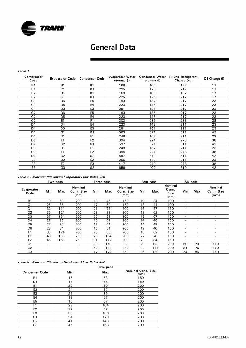
General Data
Table 1
Compressor Code Evaporator Code Condenser Code Evaporator Water
storage (l)Condenser Water
storage (l)R134a Refrigerant
Charge (kg) Oil Charge (l)
B1 B1 B1 168 106 182 17B1 C1 D1 225 125 217 17B2 B1 B1 168 106 182 17B2 C1 D1 225 125 217 17C1 D6 E5 193 132 217 23C1 D5 E4 220 148 217 23C1 D3 E3 281 181 217 23C2 D6 E5 193 135 217 23C2 D5 E4 220 148 217 23C2 E1 F1 300 235 233 38D1 D4 E4 220 148 211 23D1 D3 E3 281 181 211 23D1 G1 G1 563 321 311 42D2 D1 E1 248 167 211 23D2 F1 F2 394 224 278 38D2 G2 G1 597 321 311 42D3 D1 E1 248 167 211 23D3 F1 F2 394 224 278 38D3 G2 G2 597 370 311 42E3 D2 E2 265 178 211 23E3 F2 F3 417 240 278 38E3 G3 G3 656 400 319 42
Table 2 - Minimum/Maximum Evaporator Flow Rates (l/s)Two pass Three pass Four pass Six pass
Evaporator Code Min Max
Nominal Conn. Size
(mm)Min Max
Nominal Conn. Size
(mm)Min Max
Nominal Conn. Size (mm)
Min MaxNominal
Conn. Size (mm)
B1 19 69 200 13 46 150 10 34 100 - - -C1 25 88 200 17 59 150 13 44 100 - - -D1 32 114 200 21 76 200 16 57 150 - - -D2 35 124 200 23 83 200 18 62 150 - - -D3 37 134 200 25 89 200 18 67 150 - - -D4 27 97 200 18 64 200 14 48 150 - - -D5 27 97 200 18 64 200 14 48 150 - - -D6 23 81 200 15 54 200 12 40 150 - - -E1 35 124 200 23 83 200 18 62 150 - - -F1 43 156 250 29 104 200 22 78 150 - - -F2 46 168 250 31 112 200 23 84 150 - - -G1 - - - 39 140 250 29 105 200 20 70 150G2 - - - 42 152 250 32 114 200 21 76 150G3 - - - 47 172 250 36 129 200 24 86 150
Table 3 - Minimum/Maximum Condenser Flow Rates (l/s)Two pass
Condenser Code Min. Max Nominal Conn. Size (mm)
B1 15 53 150D1 15 53 150E1 22 80 200E2 24 87 200E3 25 89 200E4 19 67 200E5 16 57 200F1 29 104 200F2 27 97 200F3 30 106 200G1 34 123 200G2 41 148 200G3 45 163 200

RLC-PRC023-E4 13
General Data
Table 4 - Evaporator Water Pressure Drop (kPa) Water flow rates (l/s) for water only
Evap Passes Min Max 10 15 20 25 30 35 40 45 50 55 60 65 70 75 80 85 90 95 100 105 110 115 120 125 130 135 140 145 150 155 160B1 2 19 69 8 13 18 23 30 37 44 53 62 71B1 3 13 46 15 26 39 55 72 91 113B1 4 10 34 17 37 62 92 129C1 2 25 88 9 13 18 23 28 34 40 47 54 62 70 78 88C1 3 17 59 20 30 41 55 69 86 104 123C1 4 13 44 28 48 71 99 131 168D1 2 32 114 12 15 19 23 27 32 37 42 48 54 60 67 74 81 89 97D1 3 21 76 16 23 31 39 48 58 69 81 94 108 122D1 4 16 57 25 38 53 70 89 111 134 160D2 2 35 124 10 13 16 20 24 28 33 38 43 48 54 60 66 72 79 87 94 102D2 3 23 83 14 20 26 34 42 51 60 71 82 94 106 119D2 4 18 62 22 33 46 61 78 96 117 139 164D3 2 37 134 10 13 16 19 22 26 30 34 38 42 47 52 57 62 68 73 79 85 92D3 3 25 89 12 17 22 29 36 43 51 60 69 79 89 100 112D3 4 19 67 18 28 39 51 65 81 98 116 136 158D4 2 27 97 10 13 17 21 25 30 35 41 47 53 60 66 74 81D4 3 18 64 15 23 32 42 53 66 80 95 112D4 4 14 48 21 36 55 76 101 129 161D5 2 27 97 10 13 17 21 26 30 35 41 47 53 60 67 74 82D5 3 18 64 15 23 32 42 54 66 80 95 112D5 4 14 48 21 36 55 77 102 130 161D6 2 23 81 10 13 18 23 28 34 40 47 55 62 71 80D6 3 15 54 12 20 30 42 55 70 87 105D6 4 12 40 28 48 72 100 133 170E1 2 35 124 10 13 16 20 24 28 32 37 42 47 53 58 64 71 77 84 91 99E1 3 23 83 16 22 29 37 46 56 66 77 89 102 115 130E1 4 18 62 24 36 50 66 84 104 126 149 175F1 2 43 156 10 13 15 18 21 24 27 30 34 37 41 45 49 54 58 63 67 72 78 83 88 94 100F1 3 29 104 15 20 26 32 39 46 54 62 71 80 90 101 112 123 136F1 4 22 78 25 35 46 59 73 89 105 123 143 163 185F2 2 46 168 11 13 16 18 21 24 27 30 33 37 40 44 48 52 56 60 65 69 74 79 84 89 95F2 3 31 112 23 28 34 41 48 55 63 72 81 90 100 110 121 132 144F2 4 23 84 22 31 41 53 65 79 94 110 127 146 166 186G1 3 39 140 14 18 22 26 30 35 40 46 51 57 63 70 76 83 91 98 106 114 123 131 140G1 4 29 105 19 25 33 41 49 58 68 79 90 102 115 128 142 156 171 187G1 6 20 70 28 43 60 79 101 125 151 179 210 243 278G2 3 42 152 15 19 23 26 31 35 40 45 50 55 61 67 73 79 86 93 100 107 115 122 130 139G2 4 32 114 22 28 35 43 51 60 69 79 89 100 112 124 136 150 163 178G2 6 21 76 37 52 69 88 109 132 156 183 212 242 275G3 3 47 172 15 18 21 25 28 32 36 41 45 50 54 59 65 70 76 81 87 93 100 106 113 120 127G3 4 36 129 23 29 35 41 48 56 64 73 82 91 101 111 122 133 145 157 170 183G3 6 24 86 30 42 56 71 89 107 127 149 172 197 223 251 280
Table 5 - Condenser Pressure Drop (kPa) Water flow rates (l/s) for water only
Cond Passes Min Max 10 15 20 25 30 35 40 45 50 55 60 65 70 75 80 85 90 95 100 105 110 115 120 125 130 135 140 145 150 155 160B1 2 15 53 10 16 24 34 44 56 70 85D1 2 15 53 11 19 28 39 52 66 81 98E1 2 22 80 12 17 22 28 34 41 49 57 66 76 86 97E2 2 24 87 10 15 19 24 30 36 43 50 58 66 75 84 94E3 2 25 89 10 13 18 22 28 33 40 46 53 61 69 78 87E4 2 19 67 11 17 23 31 39 48 58 69 81 94E5 2 16 57 15 22 31 40 51 63 77 91F1 2 29 104 12 16 20 25 30 36 42 49 55 63 70 79 87 96 106F2 2 27 97 14 18 23 29 35 41 48 56 64 72 81 90 100 111F3 2 30 106 12 16 20 25 31 36 42 49 56 63 71 79 88 97 106 116G1 2 34 123 13 17 21 25 30 35 40 46 52 58 65 72 79 87 95 103 112 121G2 2 41 148 16 19 22 26 30 34 39 44 49 54 59 65 71 77 84 90 97 105 112 120 128G3 2 45 163 13 16 19 23 26 30 34 38 42 47 51 56 62 67 73 78 85 91 97 104 111 118 125 133
14 RLC-PRC023-E4
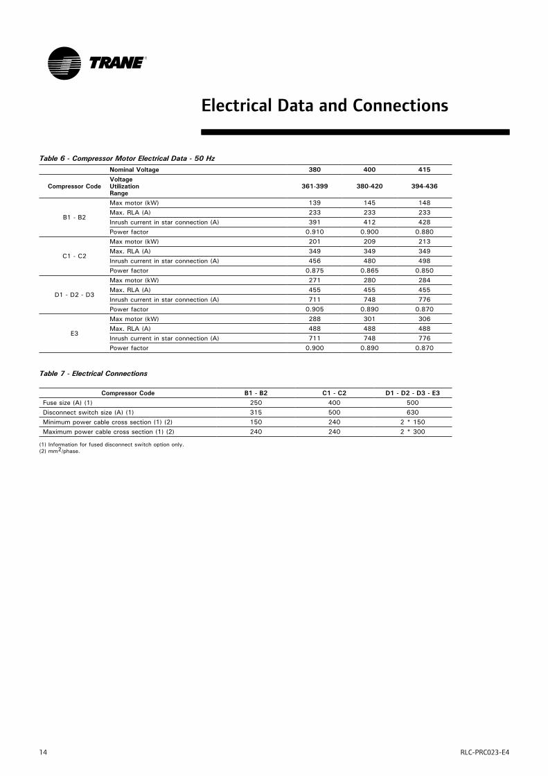
Table 6 - Compressor Motor Electrical Data - 50 HzNominal Voltage 380 400 415
Compressor CodeVoltage Utilization Range
361-399 380-420 394-436
B1 - B2
Max motor (kW) 139 145 148Max. RLA (A) 233 233 233Inrush current in star connection (A) 391 412 428Power factor 0.910 0.900 0.880
C1 - C2
Max motor (kW) 201 209 213Max. RLA (A) 349 349 349Inrush current in star connection (A) 456 480 498Power factor 0.875 0.865 0.850
D1 - D2 - D3
Max motor (kW) 271 280 284Max. RLA (A) 455 455 455Inrush current in star connection (A) 711 748 776Power factor 0.905 0.890 0.870
E3
Max motor (kW) 288 301 306Max. RLA (A) 488 488 488Inrush current in star connection (A) 711 748 776Power factor 0.900 0.890 0.870
Table 7 - Electrical Connections
Compressor Code B1 - B2 C1 - C2 D1 - D2 - D3 - E3Fuse size (A) (1) 250 400 500Disconnect switch size (A) (1) 315 500 630Minimum power cable cross section (1) (2) 150 240 2 * 150Maximum power cable cross section (1) (2) 240 240 2 * 300
(1) Information for fused disconnect switch option only.(2) mm2/phase.
Electrical Data and Connections
RLC-PRC023-E4 15
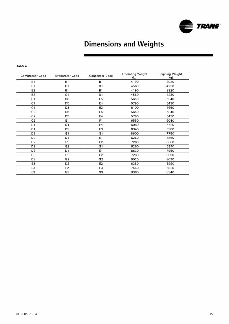
Dimensions and Weights
Table 8
Compressor Code Evaporator Code Condenser Code Operating Weight (kg)
Shipping Weight (kg)
B1 B1 B1 4190 3920B1 C1 D1 4560 4230B2 B1 B1 4190 3920B2 C1 D1 4560 4230C1 D6 E5 5650 5340C1 D5 E4 5790 5430C1 D3 E3 6100 5650C2 D6 E5 5650 5340C2 D5 E4 5790 5430C2 E1 F1 6550 6040D1 D4 E4 6080 5720D1 D3 E3 6340 5900D1 G1 G1 8600 7750D2 D1 E1 6260 5860D2 F1 F2 7260 6660D2 G2 G1 6260 5890D3 D1 E1 8830 7960D3 F1 F2 7280 6690D3 G2 G2 9020 8090E3 D2 E2 6380 5990E3 F2 F3 7450 6820E3 G3 G3 9360 8340
16 RLC-PRC023-E4
Dimensions and Weights
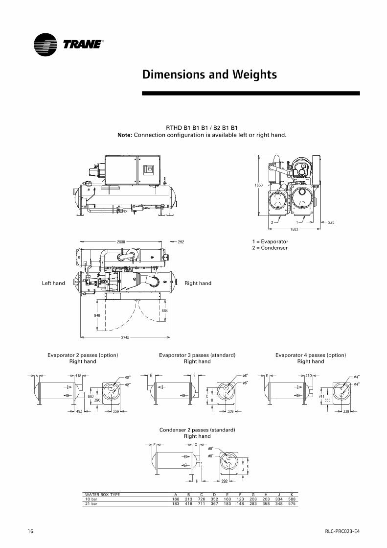
WATER BOX TYPE A B C D E F G H J K10 bar 168 213 726 352 163 123 203 203 334 58821 bar 183 418 711 367 183 148 283 358 348 575
Left hand Right hand
Evaporator 2 passes (option) Right hand
Evaporator 3 passes (standard) Right hand
Condenser 2 passes (standard) Right hand
Evaporator 4 passes (option) Right hand
1 = Evaporator2 = Condenser
RTHD B1 B1 B1 / B2 B1 B1Note: Connection configuration is available left or right hand.
RLC-PRC023-E4 17
Dimensions and Weights
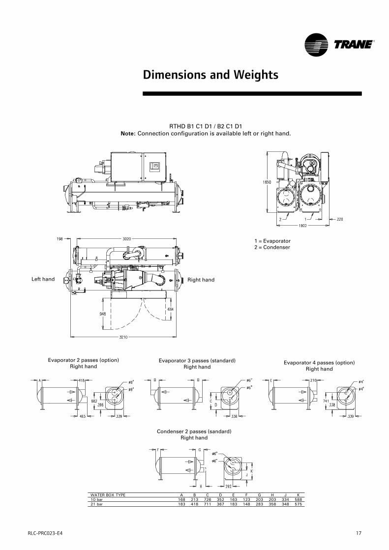
RTHD B1 C1 D1 / B2 C1 D1Note: Connection configuration is available left or right hand.
Left hand Right hand
1 = Evaporator2 = Condenser
Evaporator 2 passes (option) Right hand
Condenser 2 passes (sandard) Right hand
Evaporator 3 passes (standard) Right hand
Evaporator 4 passes (option) Right hand
WATER BOX TYPE A B C D E F G H J K10 bar 168 213 726 352 163 123 203 203 334 58821 bar 183 418 711 367 183 148 283 358 348 575
18 RLC-PRC023-E4
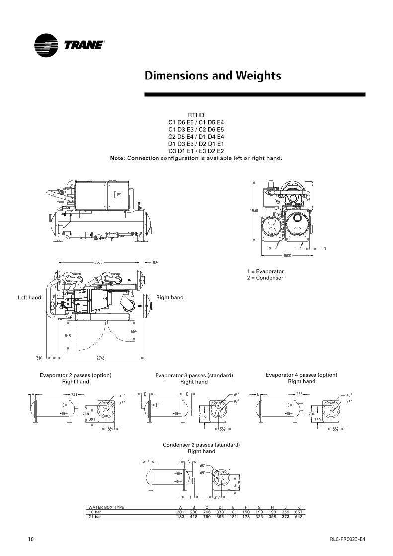
RTHD C1 D6 E5 / C1 D5 E4C1 D3 E3 / C2 D6 E5C2 D5 E4 / D1 D4 E4D1 D3 E3 / D2 D1 E1D3 D1 E1 / E3 D2 E2
Note: Connection configuration is available left or right hand.
Left hand Right hand
Evaporator 2 passes (option) Right hand
Evaporator 3 passes (standard) Right hand
Condenser 2 passes (standard) Right hand
Evaporator 4 passes (option) Right hand
1 = Evaporator2 = Condenser
Dimensions and Weights
WATER BOX TYPE A B C D E F G H J K10 bar 201 230 766 378 181 150 199 199 359 65721 bar 183 418 750 395 183 178 323 398 373 643
RLC-PRC023-E4 19
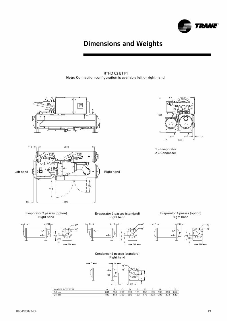
Condenser 2 passes (standard) Right hand
RTHD C2 E1 F1Note: Connection configuration is available left or right hand.
Left hand Right hand
Evaporator 2 passes (option) Right hand
Evaporator 3 passes (standard) Right hand
Evaporator 4 passes (option) Right hand
1 = Evaporator2 = Condenser
Dimensions and Weights
WATER BOX TYPE A B C D E F G H J K10 bar 201 230 766 378 181 150 199 199 359 65721 bar 183 418 750 395 183 178 323 398 373 643
20 RLC-PRC023-E4
Dimensions and Weights
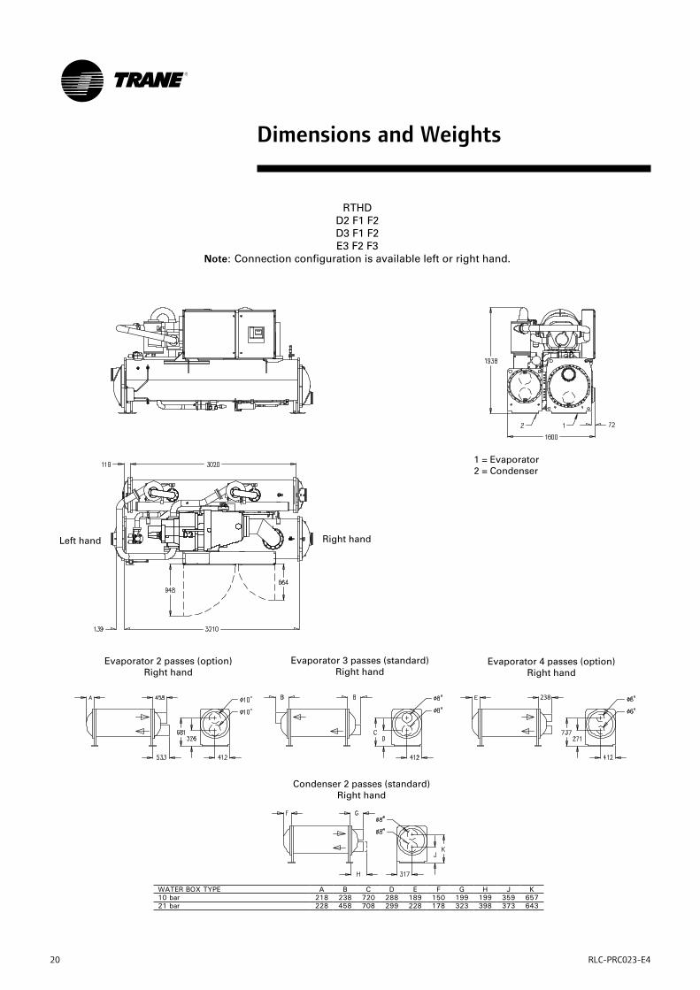
RTHDD2 F1 F2D3 F1 F2E3 F2 F3
Note: Connection configuration is available left or right hand.
Left hand Right hand
Evaporator 2 passes (option) Right hand
Evaporator 3 passes (standard) Right hand
Condenser 2 passes (standard) Right hand
Evaporator 4 passes (option) Right hand
1 = Evaporator2 = Condenser
WATER BOX TYPE A B C D E F G H J K10 bar 218 238 720 288 189 150 199 199 359 65721 bar 228 458 708 299 228 178 323 398 373 643
RLC-PRC023-E4 21
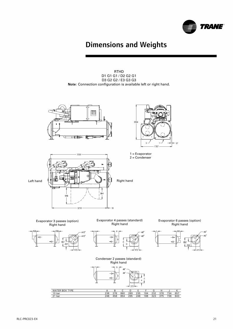
Dimensions and Weights
RTHD D1 G1 G1 / D2 G2 G1D3 G2 G2 / E3 G3 G3
Note: Connection configuration is available left or right hand.
Left hand Right hand
Condenser 2 passes (standard) Right hand
Evaporator 3 passes (option) Right hand
Evaporator 4 passes (standard) Right hand
Evaporator 6 passes (option) Right hand
1 = Evaporator2 = Condenser
WATER BOX TYPE A B C D E F G H J K10 bar 238 276 860 289 235 184 232 378 734 65721 bar 248 458 854 295 248 188 323 375 736 643
22 RLC-PRC023-E4
Mechanical Specifications
GeneralExposed steel surfaces shall be painted with an air-dry beige paint prior to shipment. Each unit shall ship with a full operating charge of refrigerant and oil. Molded neoprene isolation pads shall be supplied for placement under all support points. Startup and operator instructions by factory-trained service personnel are included.
Compressor and MotorThe unit shall have a semi-hermetic direct- drive, 3000 rpm, rotary compressor with capacity control slide valve, oil sump heater and differential pressure refrigerant oil flow system. Four pressure lubricated rolling element bearing groups shall support the rotating assembly. Motor shall be a suction gas cooled, hermetically sealed, two pole, squirrel cage induction type.
Evaporator-CondenserAll tube sheets shall be carbon steel plate. Evaporator and condenser tubes should be individually replaceable. Standard tubes shall be externally finned, internally enhanced seamless copper with lands at all tube sheets. Evaporator tubes shall be 25.4 mm diameter. Condenser tubes shall be 19.05 mm diameter. Tubes shall be mechanically expanded into tube sheets. Condenser and evaporator tubes shall be mechanically fastened to tube supports. The water boxes shall be cast iron or fabricated steel available with Victaulic connections.
Refrigerant CircuitAn electronically controlled expansion valve shall be provided to maintain proper refrigerant flow.
Unit Controls (CH.530)The microprocessor-based control panel is factory-installed and factory-tested. The control system is powered by a control power transformer, and will load and unload the chiller through adjustment of the compressor slide valve. Microprocessor-based chilled water reset based on return water is standard. The CH.530 utilizing the «Adaptive ControlTM» microprocessor automatically shall take action to prevent unit shutdown due to
abnormal operating conditions associated with low evaporator refrigerant temperature, high condensing temperature, and motor current overload. If the abnormal operating condition continues and protective limit is reached, the machine will be shut down. The panel shall include machine protection shutdown requiring manual reset for:
• Low evaporator refrigerant Temperature and pressure
• High condenser refrigerant pressure
• Low oil flow
• Critical sensor or detection circuit fault
• Motor current overload
• High compressor discharge temperature
• Communications lost between modules
• Electrical distribution faults: phase loss, phase imbalance, phase reversal
• External and local emergency stop
• Starter transition failure.
The panel shall include machine protection shutdown with automatic reset when the condition is corrected for:
• Momentary power loss
• Over / under voltage
• Loss of evaporator or condenser water flow.
Over 100 diagnostic checks shall be made and displayed when a fault is detected. The display shall indicate the fault, the type of reset required, the time and date the diagnostic occurred, the mode in which the machine was operating at the time of the diagnostic, and a help message. A diagnostic history shall display the last 20 diagnostics with the time and date of their occurrence.
RLC-PRC023-E4 23
Mechanical Specifications
Clear Language Display PanelFactory-mounted to the control panel door, the operator interface has an LCD touch-screen display for operator input and information output. This interface provides access to the following information: evaporator report, condenser report, compressor report, operator settings, service settings, service tests, and diagnostics. All diagnostics and messages are displayed in «clear language.» Data contained in available reports includes:
• Water and air temperatures
• Refrigerant levels and temperatures
• Oil pressure
• Flow switch status
• EXV position
• Head pressure control command
• Compressor starts and run-time
• Line phase percent RLA, amps, and volts
All necessary settings and setpoints are programmed into the microprocessor-based controller via the operator interface. The controller is capable of receiving signals contemporaneously from a variety of control sources, in any combination, and priority order of control sources can be programmed.The control source with priority determines active setpoints via the signal it sends to the control panel.Control sources may be:
• the local operator interface (standard)
• a 4-20 mA or 2-10 VDC signal from an external source (interface optional; control source not supplied)
• Trane Tracer Summit™ system (interface optional)
• Generic BAS (optional points; control source not supplied)
• LonTalk LCI-C (interface optional; control source not supplied)
Unit-Mounted StarterThe starter is available in a Star-Delta configuration, factory-mounted and fully pre-wired to the compressor motor and control panel. A factory-installed, factory-wired 600VA control power transformer provides all unit control power (120 VAC secondary) and CH.530 module power (24 VAC secondary). Optional starter features include circuit breaker, fused disconnect switch, non-fused disconnect switch.
OptionsDisconnect switchOptional starter features include circuit breaker, fused disconnect switch, non fused disconnect switch.The disconnect switch is also mechanically interlocked to disconnect line power from the starter before the starter door is open.
Nitrogen ChargeUnit is shipped with a nitrogen holding charge in lieu of refrigerant (No oil charge).
Holding chargeUnit is shipped with a holding R134a charge and full oil charge.
InsulationAll low temperature surfaces are covered with 19 mm of armaflex (K=0.28), including the evaporator and water boxes, suction line and motor housing .
Cupronickel condenser tubesCupronickel condenser tubes are available for special applications. 90/10 cupronickel tubes are ¾” diameter and 0.035” wall thickness.

24 RLC-PRC023-E4
Mechanical Specifications
Programmable Relays (Alarm and Status)CH.530 provides a flexible alarm or chiller status indication to a remote location through a hard wired interface to a dry contact closure. Four relays are available for this function, and they are provided (generally with a Quad Relay Output LLID) as part of the Alarm Relay Output Option. The events/states that can be assigned to the programmable relays are listed in the installation manual RLC-SVX05A.
External Base Loading Primarily for process control requirements, base loading provides for immediate start and loading of a chiller up to an externally or remotely adjustable current limit setpoint without regard to differential to start or stop, or to leaving water temperature control. This allows the flexibility to prestart or preload a chiller in anticipation of a large load application. It also allows you to keep a chiller on line between processes when leaving water temperature control would normally cycle the unit.
Summit Interface CH.530 provides an optional interface between the chiller and a Trane Summit BAS. A Communications interface LLID shall be used to provide «gateway» functionality between the Chiller and Summit.
LonTalk Communication Interface CH.530 provides an optional LonTalk Communication Interface (LCI-C) between the chiller and a Building Automation System (BAS). An LCI-C LLID shall be used to provide «gateway» functionality between the LonTalk protocol and the Chiller.
Ice Making Control CH.530 accepts a contact closure input to initiate Ice Building. When in the ice building mode, the compressor will be fully loaded (not given a low setpoint) and will continue to operate until the ice contacts open or the return water temperature reaches the Ice Termination Setpoint. If terminated on return setpoint, CH.530 will not allow the chiller to restart until the ice making contact is opened.
Ice Machine Contact CH.530 provides an output contact closure that can be used as a signal to the system that ice building is in operation. This relay will be closed when ice building is in progress and open when ice building has been terminated by either CH.530 or the remote interlock. It is used to signal the system changes required to convert to and from ice making.
External Chilled Water Setpoint CH.530 will accept either a 2-10 VDC or a 4-20mA input signal, to adjust the chilled water setpoint from a remote location.
External Current Limit Setpoint CH.530 will accept either a 2-10VDC or a 4-20mA input signal to adjust the current limit setpoint from a remote location.
Percent Condenser Pressure Output CH.530 provides a 2-10 VDC analog output to indicate percent High Pressure Cutout (HPC) condenser pressure.Percent HPC = (Condenser Pressure/High Pressure Cutout Setpoint)*100
Compressor Percent RLA Output CH.530 provides a 0-10 Vdc analog output to indicate %RLA of compressor starter average phase current. 2 to 10 Vdc corresponds to 0 to 120%RLA.
RLC-PRC023-E4 25
Notes
26 RLC-PRC023-E4
Notes
RLC-PRC023-E4 27
Notes

Trane optimizes the performance of homes and buildings around the world. A business of Ingersoll Rand, the leader in creating and sustaining safe, comfortable and energy efficient environments, Trane offers a broad portfolio of advanced controls and HVAC systems, comprehensive building services, and parts.For more information, visit www.Trane.com.
Trane has a policy of continuous product and product data improvement and reserves the right to change design and specifications without notice.
© 2012 Trane All rights reserved RLC-PRC023-E4_1112 Supersedes: RLC-PRC023-E4_0512
We are committed to using environmentally conscious print practices that reduce waste.