Embed Size (px)
Citation preview
SERIES PRA AND TRB ISO 15552 PNEUMATIC CYLINDERS
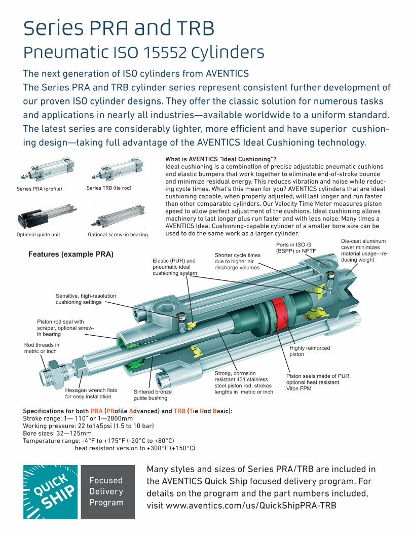
Series PRA and TRBPneumatic ISO 15552 CylindersThe next generation of ISO cylinders from AVENTICSThe Series PRA and TRB cylinder series represent consistent further development of our proven ISO cylinder designs. They off er the classic solution for numerous tasks and applications in nearly all industries—available worldwide to a uniform standard. The latest series are considerably lighter, more effi cient and have superior cushion-ing design—taking full advantage of the AVENTICS Ideal Cushioning technology.
What is AVENTICS “Ideal Cushioning”?Ideal cushioning is a combination of precise adjustable pneumatic cushions and elastic bumpers that work together to eliminate end-of-stroke bounce and minimize residual energy. This reduces vibration and noise while reduc-ing cycle times. What’s this mean for you? AVENTICS cylinders that are ideal cushioning capable, when properly adjusted, will last longer and run faster than other comparable cylinders. Our Velocity Time Meter measures piston speed to allow perfect adjustment of the cushions. Ideal cushioning allows machinery to last longer plus run faster and with less noise. Many times a AVENTICS Ideal Cushioning-capable cylinder of a smaller bore size can be used to do the same work as a larger cylinder.
Series PRA (profile) Series TRB (tie rod)
Optional guide unit Optional screw-in bearing
Specifications for both PRA (PRofile Advanced) and TRB (Tie Rod Basic):Stroke range: 1— 110” or 1—2800mmWorking pressure: 22 to145psi (1.5 to 10 bar)Bore sizes: 32—125mmTemperature range: -4°F to +175°F (-20°C to +80°C)
heat resistant version to +300°F (+150°C)
Many styles and sizes of Series PRA/TRB are included in the AVENTICS Quick Ship focused delivery program. For details on the program and the part numbers included, visit www.aventics.com/us/QuickShipPRA-TRB
Sensitive, high-resolution cushioning settings
Features (example PRA)
Piston rod seal with scraper, optional screw-in bearing
Rod threads in metric or inch
Hexagon wrench flats for easy installation
Elastic (PUR) and pneumatic ideal cushioning system
Sintered bronze guide bushing
Strong, corrosion resistant 431 stainless steel piston rod, strokes lengths in metric or inch
Shorter cycle times due to higher air discharge volumes
Ports in ISO-G (BSPP) or NPTF
Die-cast aluminum cover minimizes material usage—re-ducing weight
Highly reinforced piston
Piston seals made of PUR, optional heat resistant Viton FPM
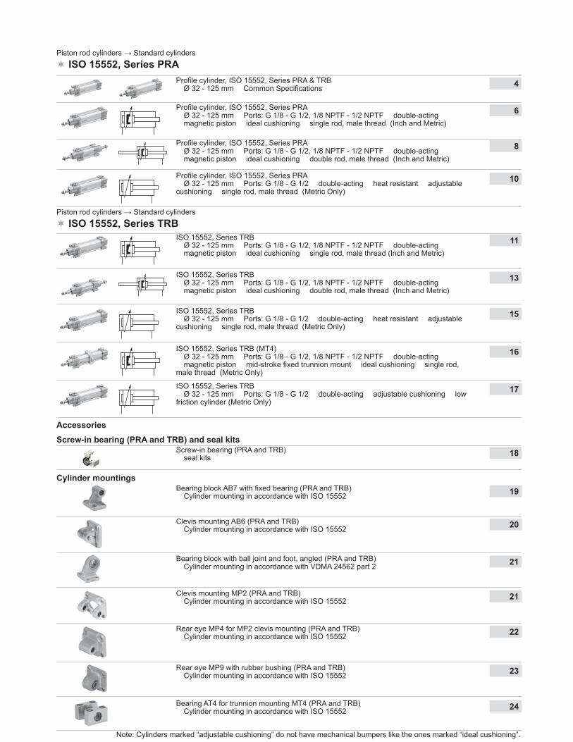
Piston rod cylinders → Standard cylinders ISO 15552, Series PRA
Profi le cylinder, ISO 15552, Series PRA� Ø 32 - 125 mm � Ports: G 1/8 - G 1/2, 1/8 NPTF - 1/2 NPTF � double-acting� magnetic piston � ideal cushioning � single rod, male thread (Inch and Metric)
6
Profi le cylinder, ISO 15552, Series PRA� Ø 32 - 125 mm � Ports: G 1/8 - G 1/2, 1/8 NPTF - 1/2 NPTF � double-acting� magnetic piston � ideal cushioning � double rod, male thread (Inch and Metric)
8
Profi le cylinder, ISO 15552, Series PRA� Ø 32 - 125 mm � Ports: G 1/8 - G 1/2 � double-acting � heat resistant � adjustablecushioning � single rod, male thread (Metric Only)
10
Accessories
Cylinder mountings Bearing block AB7 with fi xed bearing (PRA and TRB)
� Cylinder mounting in accordance with ISO 15552 19
Clevis mounting AB6 (PRA and TRB)� Cylinder mounting in accordance with ISO 15552 20
Bearing block with ball joint and foot, angled (PRA and TRB)� Cylinder mounting in accordance with VDMA 24562 part 2 21
Clevis mounting MP2 (PRA and TRB)� Cylinder mounting in accordance with ISO 15552 21
Rear eye MP4 for MP2 clevis mounting (PRA and TRB)� Cylinder mounting in accordance with ISO 15552 22
Rear eye MP9 with rubber bushing (PRA and TRB)� Cylinder mounting in accordance with ISO 15552 23
Piston rod cylinders → Standard cylinders ISO 15552, Series TRB
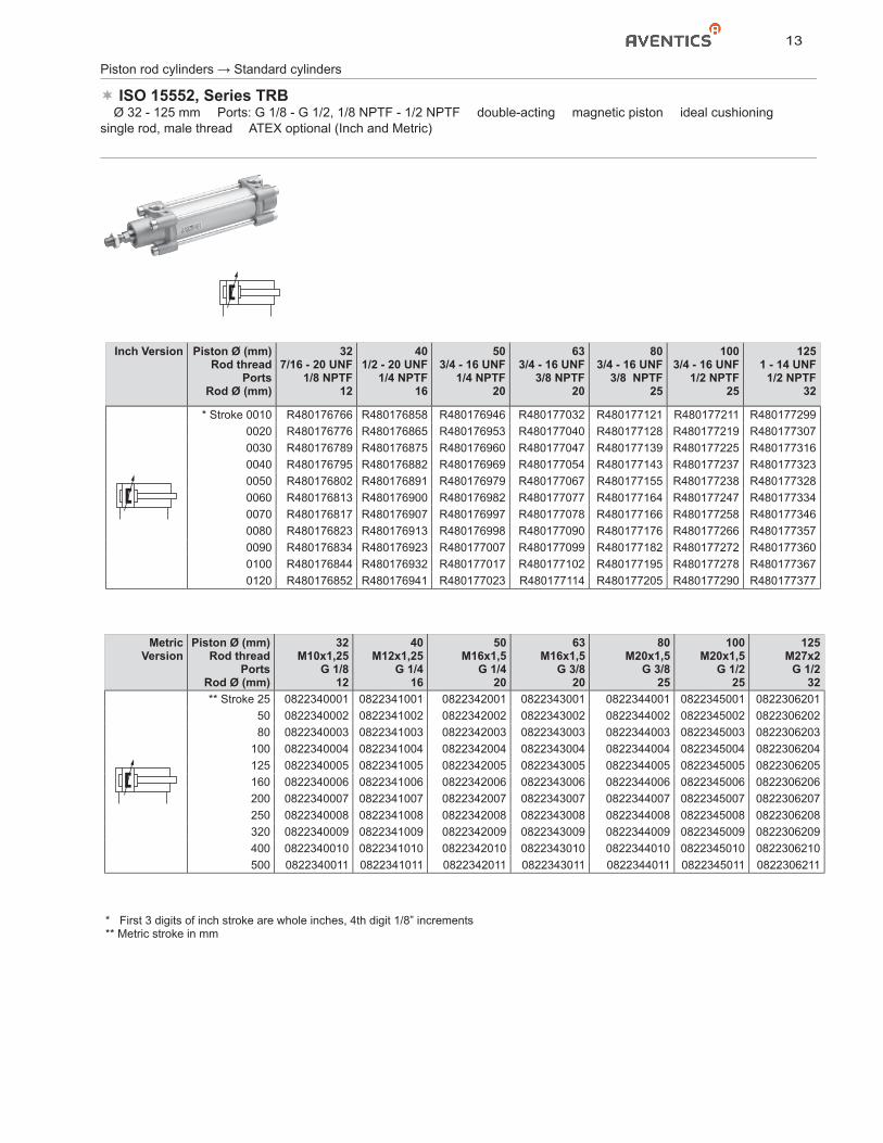
ISO 15552, Series TRB� Ø 32 - 125 mm � Ports: G 1/8 - G 1/2, 1/8 NPTF - 1/2 NPTF � double-acting� magnetic piston � ideal cushioning � single rod, male thread (Inch and Metric)
11
ISO 15552, Series TRB� Ø 32 - 125 mm � Ports: G 1/8 - G 1/2, 1/8 NPTF - 1/2 NPTF � double-acting� magnetic piston � ideal cushioning � double rod, male thread (Inch and Metric)
13
ISO 15552, Series TRB (MT4)� Ø 32 - 125 mm � Ports: G 1/8 - G 1/2, 1/8 NPTF - 1/2 NPTF � double-acting� magnetic piston � mid-stroke fi xed trunnion mount � ideal cushioning � single rod,male thread (Metric Only)
16
ISO 15552, Series TRB� Ø 32 - 125 mm � Ports: G 1/8 - G 1/2 � double-acting � heat resistant � adjustablecushioning � single rod, male thread (Metric Only)
15
ISO 15552, Series TRB� Ø 32 - 125 mm � Ports: G 1/8 - G 1/2 � double-acting � adjustable cushioning � lowfriction cylinder (Metric Only)
17
Bearing AT4 for trunnion mounting MT4 (PRA and TRB)� Cylinder mounting in accordance with ISO 15552 24
Screw-in bearing (PRA and TRB)� seal kits 18
Note: Cylinders marked “adjustable cushioning” do not have mechanical bumpers like the ones marked “ideal cushioning”.
Screw-in bearing (PRA and TRB) and seal kits
Profi le cylinder, ISO 15552, Series PRA & TRB� Ø 32 - 125 mm � Common Specifi cations 4
4
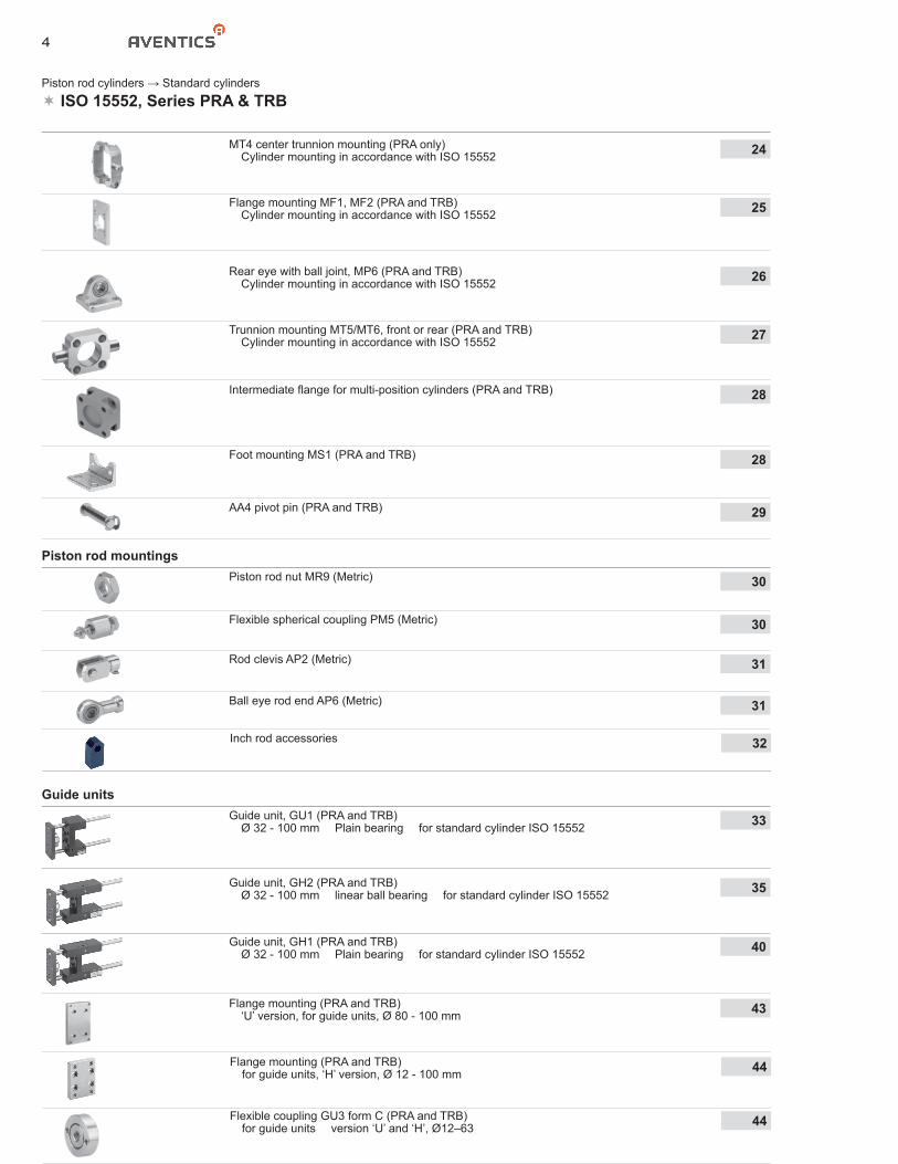
Flange mounting (PRA and TRB)� ‘U’ version, for guide units, Ø 80 - 100 mm 43
Flange mounting (PRA and TRB)� for guide units, ‘H’ version, Ø 12 - 100 mm 44
Flexible coupling GU3 form C (PRA and TRB)� for guide units � version ‘U’ and ‘H’, Ø12–63 44
Piston rod cylinders → Standard cylinders ISO 15552, Series PRA & TRB
Intermediate fl ange for multi-position cylinders (PRA and TRB) 28
Foot mounting MS1 (PRA and TRB) 28
AA4 pivot pin (PRA and TRB) 29
Piston rod mountings
Piston rod nut MR9 (Metric) 30
Flexible spherical coupling PM5 (Metric) 30
Rod clevis AP2 (Metric) 31
Ball eye rod end AP6 (Metric) 31
Guide units
Guide unit, GU1 (PRA and TRB) � Ø 32 - 100 mm � Plain bearing � for standard cylinder ISO 15552 33
Guide unit, GH2 (PRA and TRB)� Ø 32 - 100 mm � linear ball bearing � for standard cylinder ISO 15552 35
Guide unit, GH1 (PRA and TRB)� Ø 32 - 100 mm � Plain bearing � for standard cylinder ISO 15552 40
MT4 center trunnion mounting (PRA only)� Cylinder mounting in accordance with ISO 15552 24
Flange mounting MF1, MF2 (PRA and TRB)� Cylinder mounting in accordance with ISO 15552 25
Rear eye with ball joint, MP6 (PRA and TRB)� Cylinder mounting in accordance with ISO 15552 26
Trunnion mounting MT5/MT6, front or rear (PRA and TRB)� Cylinder mounting in accordance with ISO 15552 27
Inch rod accessories 32
5
Piston rod cylinders → Standard cylinders ISO 15552, Series PRA & TRB
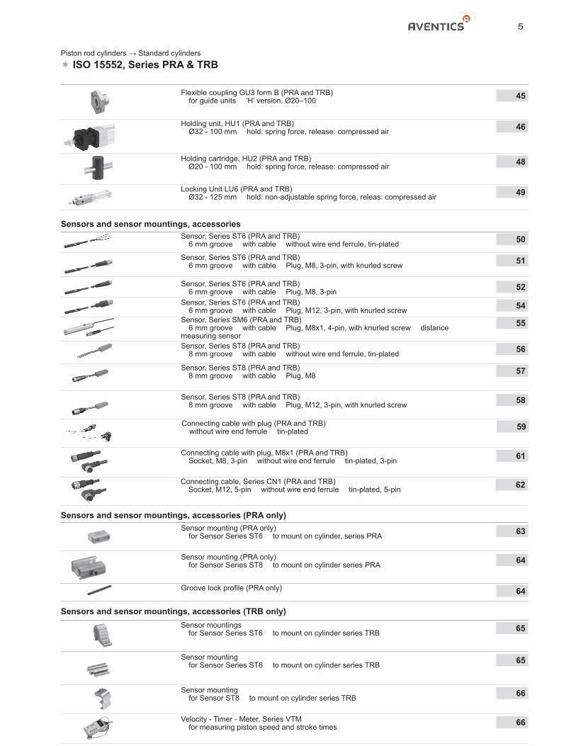
Holding unit, HU1 (PRA and TRB)� Ø32 - 100 mm � hold: spring force, release: compressed air 46
Holding cartridge, HU2 (PRA and TRB)� Ø20 - 100 mm � hold: spring force, release: compressed air 48
Sensors and sensor mountings, accessories Sensor, Series ST6 (PRA and TRB)
� 6 mm groove � with cable � without wire end ferrule, tin-plated 50
Sensor, Series ST6 (PRA and TRB)� 6 mm groove � with cable � Plug, M8, 3-pin, with knurled screw 51
Sensor, Series ST6 (PRA and TRB)� 6 mm groove � with cable � Plug, M8, 3-pin 52
Sensor, Series ST6 (PRA and TRB)� 6 mm groove � with cable � Plug, M12, 3-pin, with knurled screw 54
Sensor, Series ST8 (PRA and TRB)� 8 mm groove � with cable � without wire end ferrule, tin-plated 56
Sensor, Series ST8 (PRA and TRB)� 8 mm groove � with cable � Plug, M8 57
Sensor, Series ST8 (PRA and TRB)� 8 mm groove � with cable � Plug, M12, 3-pin, with knurled screw 58
Sensor mounting (PRA only)� for Sensor Series ST6 � to mount on cylinder, series PRA 63
Flexible coupling GU3 form B (PRA and TRB)� for guide units � ‘H’ version, Ø20–100 45
Sensor mounting (PRA only)� for Sensor Series ST8 � to mount on cylinder series PRA 64
Groove lock profi le (PRA only) 64
Sensor mountings� for Sensor Series ST6 � to mount on cylinder series TRB 65
Sensor mounting� for Sensor Series ST6 � to mount on cylinder series TRB 65
Sensor mounting� for Sensor ST8 � to mount on cylinder series TRB 66
Sensors and sensor mountings, accessories (TRB only)
Connecting cable with plug (PRA and TRB)� without wire end ferrule � tin-plated 59
Connecting cable with plug, M8x1 (PRA and TRB)� Socket, M8, 3-pin � without wire end ferrule � tin-plated, 3-pin 61
Velocity - Timer - Meter, Series VTM� for measuring piston speed and stroke times 66
Sensors and sensor mountings, accessories (PRA only)
Connecting cable, Series CN1 (PRA and TRB)� Socket, M12, 5-pin � without wire end ferrule � tin-plated, 5-pin 62
Locking Unit LU6 (PRA and TRB)� Ø32 - 125 mm � hold: non-adjustable spring force, releas: compressed air 49
Sensor, Series SM6 (PRA and TRB)� 6 mm groove � with cable � Plug, M8x1, 4-pin, with knurled screw � distancemeasuring sensor
55
6
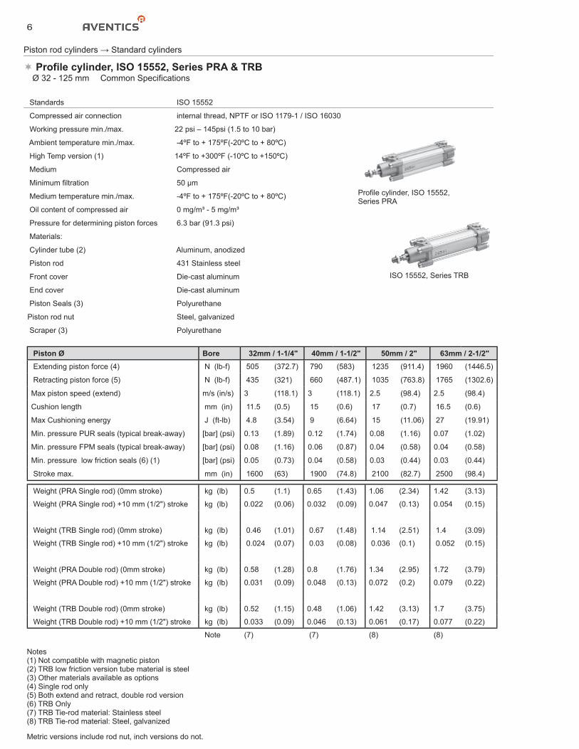
Piston Ø Bore 32mm / 1-1/4" 40mm / 1-1/2" 50mm / 2" 63mm / 2-1/2" Extending piston force (4) N (lb-f) 505 (372.7) 790 (583) 1235 (911.4) 1960 (1446.5)
Retracting piston force (5) N (lb-f) 435 (321) 660 (487.1) 1035 (763.8) 1765 (1302.6)
Max piston speed (extend) m/s (in/s) 3 (118.1) 3 (118.1) 2.5 (98.4) 2.5 (98.4)
Cushion length mm (in) 11.5 (0.5) 15 (0.6) 17 (0.7) 16.5 (0.6)
Max Cushioning energy J (ft-lb) 4.8 (3.54) 9 (6.64) 15 (11.06) 27 (19.91)
Min. pressure PUR seals (typical break-away) [bar] (psi) 0.13 (1.89) 0.12 (1.74) 0.08 (1.16) 0.07 (1.02)
Min. pressure FPM seals (typical break-away) [bar] (psi) 0.08 (1.16) 0.06 (0.87) 0.04 (0.58) 0.04 (0.58)
Min. pressure low friction seals (6) (1) [bar] (psi) 0.05 (0.73) 0.04 (0.58) 0.03 (0.44) 0.03 (0.44)
Stroke max. mm (in) 1600 (63) 1900 (74.8) 2100 (82.7) 2500 (98.4)
Weight (PRA Single rod) (0mm stroke) kg (lb) 0.5 (1.1) 0.65 (1.43) 1.06 (2.34) 1.42 (3.13)
Weight (PRA Single rod) +10 mm (1/2") stroke kg (lb) 0.022 (0.06) 0.032 (0.09) 0.047 (0.13) 0.054 (0.15)
Weight (TRB Single rod) (0mm stroke) kg (lb) 0.46 (1.01) 0.67 (1.48) 1.14 (2.51) 1.4 (3.09)
Weight (TRB Single rod) +10 mm (1/2") stroke kg (lb) 0.024 (0.07) 0.03 (0.08) 0.036 (0.1) 0.052 (0.15)
Weight (PRA Double rod) (0mm stroke) kg (lb) 0.58 (1.28) 0.8 (1.76) 1.34 (2.95) 1.72 (3.79)
Weight (PRA Double rod) +10 mm (1/2") stroke kg (lb) 0.031 (0.09) 0.048 (0.13) 0.072 (0.2) 0.079 (0.22)
Weight (TRB Double rod) (0mm stroke) kg (lb) 0.52 (1.15) 0.48 (1.06) 1.42 (3.13) 1.7 (3.75)
Weight (TRB Double rod) +10 mm (1/2") stroke kg (lb) 0.033 (0.09) 0.046 (0.13) 0.061 (0.17) 0.077 (0.22)
Note (7) (7) (8) (8)
Standards ISO 15552
Compressed air connection internal thread, NPTF or ISO 1179-1 / ISO 16030
Working pressure min./max. 22 psi – 145psi (1.5 to 10 bar)
Ambient temperature min./max. -4ºF to + 175ºF(-20ºC to + 80ºC)
High Temp version (1) 14ºF to +300ºF (-10ºC to +150ºC)
Medium Compressed air
Minimum filtration 50 μm
Medium temperature min./max. -4ºF to + 175ºF(-20ºC to + 80ºC)
Oil content of compressed air 0 mg/m³ - 5 mg/m³
Pressure for determining piston forces 6.3 bar (91.3 psi)
Materials:
Cylinder tube (2) Aluminum, anodized
Piston rod 431 Stainless steel
Front cover Die-cast aluminum
End cover Die-cast aluminum
Piston Seals (3) Polyurethane
Piston rod nut Steel, galvanized
Scraper (3) Polyurethane
Notes(1) Not compatible with magnetic piston(2) TRB low friction version tube material is steel(3) Other materials available as options(4) Single rod only(5) Both extend and retract, double rod version(6) TRB Only(7) TRB Tie-rod material: Stainless steel(8) TRB Tie-rod material: Steel, galvanized
Piston rod cylinders → Standard cylinders
Profile cylinder, ISO 15552, Series PRA & TRB� Ø 32 - 125 mm � Common Specifications
Profile cylinder, ISO 15552, Series PRA
ISO 15552, Series TRB
Metric versions include rod nut, inch versions do not.
7
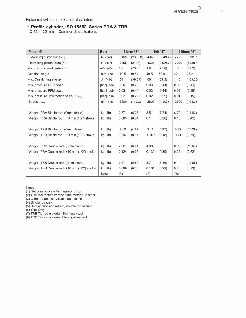
Piston Ø Bore 80mm / 3" 100 / 4" 125mm / 5" Extending piston force (3) N (lb-f) 3165 (2335.8) 4945 (3649.4) 7725 (5701.1)
Retracting piston force (4) N (lb-f) 2855 (2107) 4635 (3420.6) 7220 (5328.4)
Max piston speed (extend) m/s (in/s) 1.8 (70.8) 1.8 (70.8) 1.2 (47.2)
Cushion length mm (in) 19.5 (0.8) 19.5 70.9 22 47.2
Max Cushioning energy J (ft-lb) 54 (39.83) 88 (64.9) 140 (103.25)
Min. pressure PUR seals [bar] (psi) 0.05 (0.73) 0.03 (0.44) 0.03 (0.44)
Min. pressure FPM seals [bar] (psi) 0.03 (0.44) 0.03 (0.44) 0.02 (0.29)
Min. pressure low friction seals (5) (6) [bar] (psi) 0.02 (0.29) 0.02 (0.29) 0.01 (0.15)
Stroke max. mm (in) 2800 (110.2) 2800 (110.2) 2750 (108.3)
Weight (PRA Single rod) (0mm stroke) kg (lb) 2.37 (5.23) 3.51 (7.74) 6.72 (14.82)
Weight (PRA Single rod) +10 mm (1/2") stroke kg (lb) 0.085 (0.24) 0.1 (0.28) 0.15 (0.42)
Weight (TRB Single rod) (0mm stroke) kg (lb) 2.12 (4.67) 3.16 (6.97) 6.92 (15.26)
Weight (TRB Single rod) +10 mm (1/2") stroke kg (lb) 0.06 (0.17) 0.065 (0.18) 0.21 (0.59)
Weight (PRA Double rod) (0mm stroke) kg (lb) 2.92 (6.44) 4.08 (9) 8.92 (19.67)
Weight (PRA Double rod) +10 mm (1/2") stroke kg (lb) 0.124 (0.35) 0.139 (0.39) 0.22 (0.62)
Weight (TRB Double rod) (0mm stroke) kg (lb) 2.67 (5.89) 3.7 (8.16) 9 (19.85)
Weight (TRB Double rod) +10 mm (1/2") stroke kg (lb) 0.099 (0.28) 0.104 (0.29) 0.26 (0.73)
Note (8) (8) (8)
Notes(1) Not compatible with magnetic piston(2) TRB low friction version tube material is steel(3) Other materials available as options(4) Single rod only(5) Both extend and retract, double rod version(6) TRB Only(7) TRB Tie-rod material: Stainless steel(8) TRB Tie-rod material: Steel, galvanized
Piston rod cylinders → Standard cylinders
Profile cylinder, ISO 15552, Series PRA & TRB� Ø 32 - 125 mm � Common Specifications
8
Piston rod cylinders → Standard cylinders
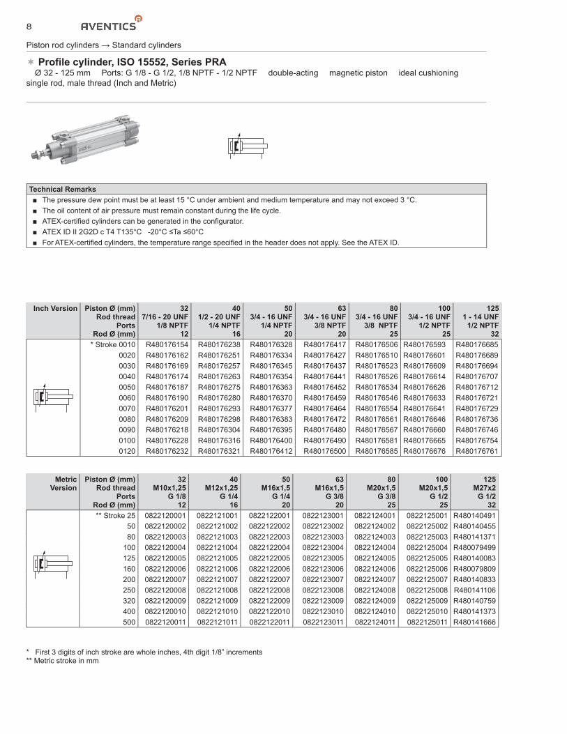
Profile cylinder, ISO 15552, Series PRA� Ø 32 - 125 mm � Ports: G 1/8 - G 1/2, 1/8 NPTF - 1/2 NPTF � double-acting � magnetic piston � ideal cushioning � single rod, male thread (Inch and Metric)
Technical Remarks■ The pressure dew point must be at least 15 °C under ambient and medium temperature and may not exceed 3 °C.■ The oil content of air pressure must remain constant during the life cycle.■ ATEX-certified cylinders can be generated in the configurator.■ ATEX ID II 2G2D c T4 T135°C -20°C ≤Ta ≤60°C■ For ATEX-certified cylinders, the temperature range specified in the header does not apply. See the ATEX ID.
Inch Version Piston Ø (mm)Rod thread
PortsRod Ø (mm)
327/16 - 20 UNF
1/8 NPTF12
401/2 - 20 UNF
1/4 NPTF16
503/4 - 16 UNF
1/4 NPTF20
633/4 - 16 UNF
3/8 NPTF20
803/4 - 16 UNF
3/8 NPTF25
1003/4 - 16 UNF
1/2 NPTF25
1251 - 14 UNF
1/2 NPTF32
* Stroke 0010 R480176154 R480176238 R480176328 R480176417 R480176506 R480176593 R4801766850020 R480176162 R480176251 R480176334 R480176427 R480176510 R480176601 R4801766890030 R480176169 R480176257 R480176345 R480176437 R480176523 R480176609 R4801766940040 R480176174 R480176263 R480176354 R480176441 R480176526 R480176614 R4801767070050 R480176187 R480176275 R480176363 R480176452 R480176534 R480176626 R4801767120060 R480176190 R480176280 R480176370 R480176459 R480176546 R480176633 R4801767210070 R480176201 R480176293 R480176377 R480176464 R480176554 R480176641 R4801767290080 R480176209 R480176298 R480176383 R480176472 R480176561 R480176646 R4801767360090 R480176218 R480176304 R480176395 R480176480 R480176567 R480176660 R4801767460100 R480176228 R480176316 R480176400 R480176490 R480176581 R480176665 R4801767540120 R480176232 R480176321 R480176412 R480176500 R480176585 R480176676 R480176761
MetricVersion
Piston Ø (mm)Rod thread
PortsRod Ø (mm)
32M10x1,25
G 1/812
40M12x1,25
G 1/416
50M16x1,5
G 1/420
63M16x1,5
G 3/820
80M20x1,5
G 3/825
100M20x1,5
G 1/225
125M27x2
G 1/232
** Stroke 25 0822120001 0822121001 0822122001 0822123001 0822124001 0822125001 R48014049150 0822120002 0822121002 0822122002 0822123002 0822124002 0822125002 R48014045580 0822120003 0822121003 0822122003 0822123003 0822124003 0822125003 R480141371
100 0822120004 0822121004 0822122004 0822123004 0822124004 0822125004 R480079499125 0822120005 0822121005 0822122005 0822123005 0822124005 0822125005 R480140083160 0822120006 0822121006 0822122006 0822123006 0822124006 0822125006 R480079809200 0822120007 0822121007 0822122007 0822123007 0822124007 0822125007 R480140833250 0822120008 0822121008 0822122008 0822123008 0822124008 0822125008 R480141106320 0822120009 0822121009 0822122009 0822123009 0822124009 0822125009 R480140759400 0822120010 0822121010 0822122010 0822123010 0822124010 0822125010 R480141373500 0822120011 0822121011 0822122011 0822123011 0822124011 0822125011 R480141666
* First 3 digits of inch stroke are whole inches, 4th digit 1/8” increments** Metric stroke in mm
9
Piston rod cylinders → Standard cylinders
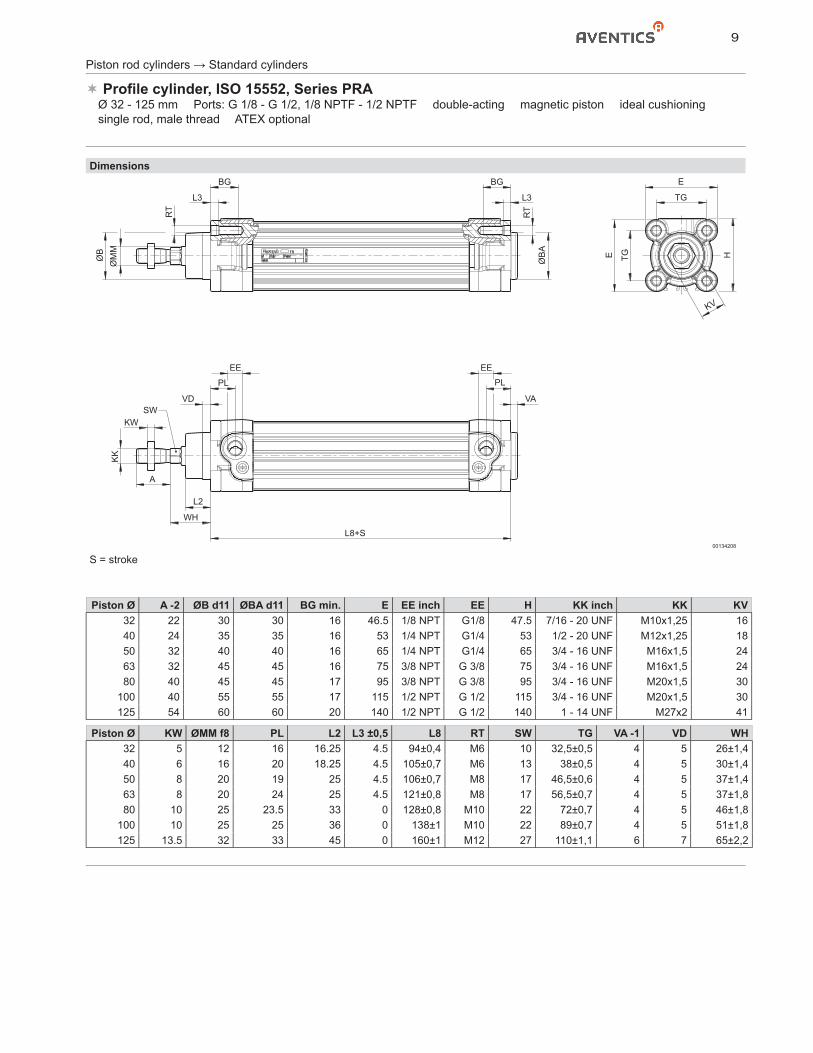
Profile cylinder, ISO 15552, Series PRA� Ø 32 - 125 mm � Ports: G 1/8 - G 1/2, 1/8 NPTF - 1/2 NPTF � double-acting � magnetic piston � ideal cushioning � single rod, male thread � ATEX optional
Dimensions
ØB
KK
KW
A
WH
L2
L8+S
SWVD
PL PL
VA
EE EE
ØB
A
ØM
M
RT
RT
BG BG E
TG
E H
KV
TG
L3L3
00134208
S = stroke
Piston Ø A -2 ØB d11 ØBA d11 BG min. E EE inch EE H KK inch KK KV32 22 30 30 16 46.5 1/8 NPT G1/8 47.5 7/16 - 20 UNF M10x1,25 1640 24 35 35 16 53 1/4 NPT G1/4 53 1/2 - 20 UNF M12x1,25 1850 32 40 40 16 65 1/4 NPT G1/4 65 3/4 - 16 UNF M16x1,5 2463 32 45 45 16 75 3/8 NPT G 3/8 75 3/4 - 16 UNF M16x1,5 2480 40 45 45 17 95 3/8 NPT G 3/8 95 3/4 - 16 UNF M20x1,5 30
100 40 55 55 17 115 1/2 NPT G 1/2 115 3/4 - 16 UNF M20x1,5 30125 54 60 60 20 140 1/2 NPT G 1/2 140 1 - 14 UNF M27x2 41
Piston Ø KW ØMM f8 PL L2 L3 ±0,5 L8 RT SW TG VA -1 VD WH32 5 12 16 16.25 4.5 94±0,4 M6 10 32,5±0,5 4 5 26±1,440 6 16 20 18.25 4.5 105±0,7 M6 13 38±0,5 4 5 30±1,450 8 20 19 25 4.5 106±0,7 M8 17 46,5±0,6 4 5 37±1,463 8 20 24 25 4.5 121±0,8 M8 17 56,5±0,7 4 5 37±1,880 10 25 23.5 33 0 128±0,8 M10 22 72±0,7 4 5 46±1,8
100 10 25 25 36 0 138±1 M10 22 89±0,7 4 5 51±1,8125 13.5 32 33 45 0 160±1 M12 27 110±1,1 6 7 65±2,2
10
Piston rod cylinders → Standard cylinders
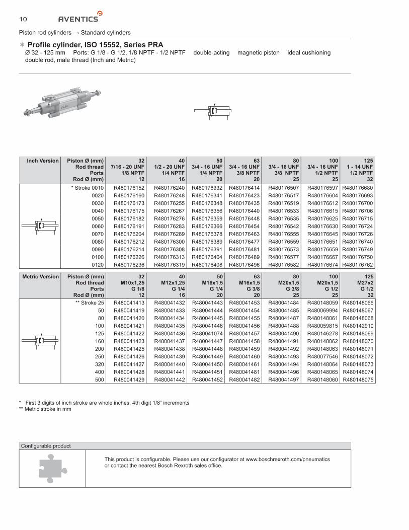
Profile cylinder, ISO 15552, Series PRA� Ø 32 - 125 mm � Ports: G 1/8 - G 1/2, 1/8 NPTF - 1/2 NPTF � double-acting � magnetic piston � ideal cushioning � double rod, male thread (Inch and Metric)
Metric Version Piston Ø (mm)Rod thread
PortsRod Ø (mm)
32M10x1,25
G 1/812
40M12x1,25
G 1/416
50M16x1,5
G 1/420
63M16x1,5
G 3/820
80M20x1,5
G 3/825
100M20x1,5
G 1/225
125M27x2
G 1/232
** Stroke 25 R480041413 R480041432 R480041443 R480041453 R480041484 R480148059 R48014806650 R480041419 R480041433 R480041444 R480041454 R480041485 R480069994 R48014806780 R480041420 R480041434 R480041445 R480041455 R480041487 R480148061 R480148068
100 R480041421 R480041435 R480041446 R480041456 R480041488 R480059815 R480142910125 R480041422 R480041436 R480041074 R480041457 R480041490 R480146278 R480148069160 R480041423 R480041437 R480041447 R480041458 R480041491 R480148062 R480148070200 R480041425 R480041438 R480041448 R480041459 R480041492 R480148063 R480148071250 R480041426 R480041439 R480041449 R480041460 R480041493 R480077546 R480148072320 R480041427 R480041440 R480041450 R480041461 R480041494 R480148064 R480148073400 R480041428 R480041441 R480041451 R480041481 R480041496 R480148065 R480148074500 R480041429 R480041442 R480041452 R480041482 R480041497 R480148060 R480148075
Configurable product
This product is configurable. Please use our configurator at www.boschrexroth.com/pneumatics or contact the nearest Bosch Rexroth sales office.
Inch Version Piston Ø (mm)Rod thread
PortsRod Ø (mm)
327/16 - 20 UNF
1/8 NPTF12
401/2 - 20 UNF
1/4 NPTF16
503/4 - 16 UNF
1/4 NPTF20
633/4 - 16 UNF
3/8 NPTF20
803/4 - 16 UNF
3/8 NPTF25
1003/4 - 16 UNF
1/2 NPTF25
1251 - 14 UNF
1/2 NPTF32
* Stroke 0010 R480176152 R480176240 R480176332 R480176414 R480176507 R480176597 R4801766800020 R480176160 R480176248 R480176341 R480176423 R480176517 R480176604 R4801766930030 R480176173 R480176255 R480176348 R480176435 R480176519 R480176612 R4801767000040 R480176175 R480176267 R480176356 R480176440 R480176533 R480176615 R4801767060050 R480176182 R480176276 R480176359 R480176448 R480176535 R480176625 R4801767150060 R480176191 R480176283 R480176366 R480176454 R480176542 R480176630 R4801767240070 R480176204 R480176289 R480176378 R480176463 R480176555 R480176645 R4801767260080 R480176212 R480176300 R480176389 R480176477 R480176559 R480176651 R4801767400090 R480176214 R480176308 R480176391 R480176481 R480176573 R480176659 R4801767490100 R480176226 R480176313 R480176404 R480176489 R480176577 R480176667 R4801767500120 R480176236 R480176319 R480176408 R480176496 R480176582 R480176674 R480176762
* First 3 digits of inch stroke are whole inches, 4th digit 1/8” increments** Metric stroke in mm
11
Piston rod cylinders → Standard cylinders
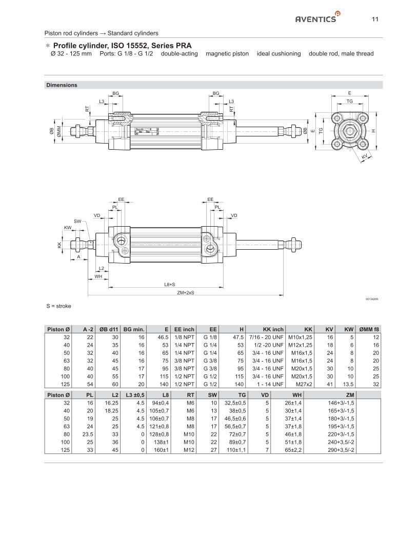
Profile cylinder, ISO 15552, Series PRA� Ø 32 - 125 mm � Ports: G 1/8 - G 1/2 � double-acting � magnetic piston � ideal cushioning � double rod, male thread
Dimensions
ØB
KK
KW
A
WH
L2
L8+S
ZM+2xS
SWVD
PL PL
VD
EE EE
ØB
ØM
M
RT
RT
BG BG
L3L3
E
TG
E H
KV
TG
00134209
S = stroke
Piston Ø A -2 ØB d11 BG min. E EE inch EE H KK inch KK KV KW ØMM f832 22 30 16 46.5 1/8 NPT G 1/8 47.5 7/16 - 20 UNF M10x1,25 16 5 1240 24 35 16 53 1/4 NPT G 1/4 53 1/2 -20 UNF M12x1,25 18 6 1650 32 40 16 65 1/4 NPT G 1/4 65 3/4 - 16 UNF M16x1,5 24 8 2063 32 45 16 75 3/8 NPT G 3/8 75 3/4 - 16 UNF M16x1,5 24 8 2080 40 45 17 95 3/8 NPT G 3/8 95 3/4 - 16 UNF M20x1,5 30 10 25
100 40 55 17 115 1/2 NPT G 1/2 115 3/4 - 16 UNF M20x1,5 30 10 25125 54 60 20 140 1/2 NPT G 1/2 140 1 - 14 UNF M27x2 41 13.5 32
Piston Ø PL L2 L3 ±0,5 L8 RT SW TG VD WH ZM32 16 16.25 4.5 94±0,4 M6 10 32,5±0,5 5 26±1,4 146+3/-1,540 20 18.25 4.5 105±0,7 M6 13 38±0,5 5 30±1,4 165+3/-1,550 19 25 4.5 106±0,7 M8 17 46,5±0,6 5 37±1,4 180+3/-1,563 24 25 4.5 121±0,8 M8 17 56,5±0,7 5 37±1,8 195+3/-1,580 23.5 33 0 128±0,8 M10 22 72±0,7 5 46±1,8 220+3/-1,5
100 25 36 0 138±1 M10 22 89±0,7 5 51±1,8 240+3,5/-2125 33 45 0 160±1 M12 27 110±1,1 7 65±2,2 290+3,5/-2
12
Piston rod cylinders → Standard cylinders
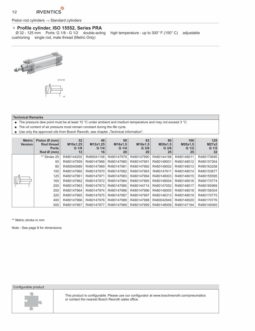
Profile cylinder, ISO 15552, Series PRA� Ø 32 - 125 mm � Ports: G 1/8 - G 1/2 � double-acting � high temperature - up to 300° F (150° C) � adjustable cushioning � single rod, male thread (Metric Only)
00134193
a5
Technical Remarks■ The pressure dew point must be at least 15 °C under ambient and medium temperature and may not exceed 3 °C.■ The oil content of air pressure must remain constant during the life cycle.■ Use only the approved oils from Bosch Rexroth, see chapter „Technical information“.
MetricVersion
Piston Ø (mm)Rod thread
PortsRod Ø (mm)
32M10x1,25
G 1/812
40M12x1,25
G 1/416
50M16x1,5
G 1/420
63M16x1,5
G 3/820
80M20x1,5
G 3/825
100M20x1,5
G 1/225
125M27x2
G 1/232
** Stroke 25 R480144202 R480041108 R480147979 R480147990 R480144198 R480148011 R48017069550 R480147959 R480147968 R480147980 R480147991 R480148001 R480148012 R48015726480 R480040989 R480147969 R480147981 R480147992 R480148002 R480148013 R480163258
100 R480147960 R480147970 R480147982 R480147993 R480147611 R480148014 R480153677125 R480147961 R480147971 R480147983 R480147994 R480148003 R480148015 R480155595160 R480147962 R480147972 R480147984 R480147995 R480148004 R480148016 R480170774200 R480147963 R480147973 R480147985 R480144714 R480147052 R480148017 R480165969250 R480147964 R480147974 R480147986 R480147996 R480148005 R480148018 R480158304320 R480147965 R480147975 R480147987 R480147997 R480146313 R480148019 R480170775400 R480147966 R480147976 R480147988 R480147998 R480042946 R480148020 R480170776500 R480147967 R480147977 R480147989 R480147999 R480148009 R480147194 R480149365
Configurable product
This product is configurable. Please use our configurator at www.boschrexroth.com/pneumatics or contact the nearest Bosch Rexroth sales office.
** Metric stroke in mm
Note - See page 8 for dimensions.
13
Piston rod cylinders → Standard cylinders
ISO 15552, Series TRB� Ø 32 - 125 mm � Ports: G 1/8 - G 1/2, 1/8 NPTF - 1/2 NPTF � double-acting � magnetic piston � ideal cushioning � single rod, male thread � ATEX optional (Inch and Metric)
MetricVersion
Piston Ø (mm)Rod thread
PortsRod Ø (mm)
32M10x1,25
G 1/812
40M12x1,25
G 1/416
50M16x1,5
G 1/420
63M16x1,5
G 3/820
80M20x1,5
G 3/825
100M20x1,5
G 1/225
125M27x2
G 1/232
** Stroke 25 0822340001 0822341001 0822342001 0822343001 0822344001 0822345001 082230620150 0822340002 0822341002 0822342002 0822343002 0822344002 0822345002 082230620280 0822340003 0822341003 0822342003 0822343003 0822344003 0822345003 0822306203
100 0822340004 0822341004 0822342004 0822343004 0822344004 0822345004 0822306204125 0822340005 0822341005 0822342005 0822343005 0822344005 0822345005 0822306205160 0822340006 0822341006 0822342006 0822343006 0822344006 0822345006 0822306206200 0822340007 0822341007 0822342007 0822343007 0822344007 0822345007 0822306207250 0822340008 0822341008 0822342008 0822343008 0822344008 0822345008 0822306208320 0822340009 0822341009 0822342009 0822343009 0822344009 0822345009 0822306209400 0822340010 0822341010 0822342010 0822343010 0822344010 0822345010 0822306210500 0822340011 0822341011 0822342011 0822343011 0822344011 0822345011 0822306211
Inch Version Piston Ø (mm)Rod thread
PortsRod Ø (mm)
327/16 - 20 UNF
1/8 NPTF12
401/2 - 20 UNF
1/4 NPTF16
503/4 - 16 UNF
1/4 NPTF20
633/4 - 16 UNF
3/8 NPTF20
803/4 - 16 UNF
3/8 NPTF25
1003/4 - 16 UNF
1/2 NPTF25
1251 - 14 UNF
1/2 NPTF32
* Stroke 0010 R480176766 R480176858 R480176946 R480177032 R480177121 R480177211 R4801772990020 R480176776 R480176865 R480176953 R480177040 R480177128 R480177219 R4801773070030 R480176789 R480176875 R480176960 R480177047 R480177139 R480177225 R4801773160040 R480176795 R480176882 R480176969 R480177054 R480177143 R480177237 R4801773230050 R480176802 R480176891 R480176979 R480177067 R480177155 R480177238 R4801773280060 R480176813 R480176900 R480176982 R480177077 R480177164 R480177247 R4801773340070 R480176817 R480176907 R480176997 R480177078 R480177166 R480177258 R4801773460080 R480176823 R480176913 R480176998 R480177090 R480177176 R480177266 R4801773570090 R480176834 R480176923 R480177007 R480177099 R480177182 R480177272 R4801773600100 R480176844 R480176932 R480177017 R480177102 R480177195 R480177278 R4801773670120 R480176852 R480176941 R480177023 R480177114 R480177205 R480177290 R480177377
* First 3 digits of inch stroke are whole inches, 4th digit 1/8” increments** Metric stroke in mm
14
Piston rod cylinders → Standard cylinders
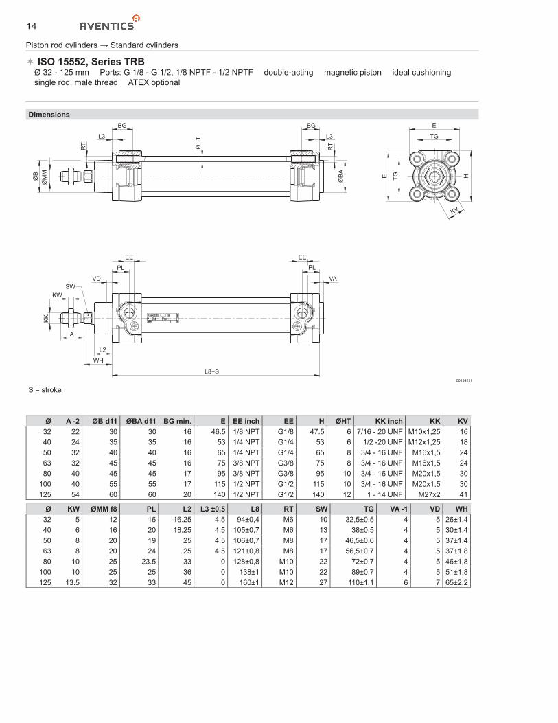
ISO 15552, Series TRB� Ø 32 - 125 mm � Ports: G 1/8 - G 1/2, 1/8 NPTF - 1/2 NPTF � double-acting � magnetic piston � ideal cushioning � single rod, male thread � ATEX optional
Dimensions
ØB
ØM
M
RT
BG
L3
ØB
A
BG
RTØH
T L3
PL
VA
EE
WH
L2
L8+S
KK
KW
A
SWVD
PL
EE
E
TG
E H
KV
TG
00134211
S = stroke
Ø A -2 ØB d11 ØBA d11 BG min. E EE inch EE H ØHT KK inch KK KV32 22 30 30 16 46.5 1/8 NPT G1/8 47.5 6 7/16 - 20 UNF M10x1,25 1640 24 35 35 16 53 1/4 NPT G1/4 53 6 1/2 -20 UNF M12x1,25 1850 32 40 40 16 65 1/4 NPT G1/4 65 8 3/4 - 16 UNF M16x1,5 2463 32 45 45 16 75 3/8 NPT G3/8 75 8 3/4 - 16 UNF M16x1,5 2480 40 45 45 17 95 3/8 NPT G3/8 95 10 3/4 - 16 UNF M20x1,5 30
100 40 55 55 17 115 1/2 NPT G1/2 115 10 3/4 - 16 UNF M20x1,5 30125 54 60 60 20 140 1/2 NPT G1/2 140 12 1 - 14 UNF M27x2 41
Ø KW ØMM f8 PL L2 L3 ±0,5 L8 RT SW TG VA -1 VD WH32 5 12 16 16.25 4.5 94±0,4 M6 10 32,5±0,5 4 5 26±1,440 6 16 20 18.25 4.5 105±0,7 M6 13 38±0,5 4 5 30±1,450 8 20 19 25 4.5 106±0,7 M8 17 46,5±0,6 4 5 37±1,463 8 20 24 25 4.5 121±0,8 M8 17 56,5±0,7 4 5 37±1,880 10 25 23.5 33 0 128±0,8 M10 22 72±0,7 4 5 46±1,8
100 10 25 25 36 0 138±1 M10 22 89±0,7 4 5 51±1,8125 13.5 32 33 45 0 160±1 M12 27 110±1,1 6 7 65±2,2
15
Piston rod cylinders → Standard cylinders
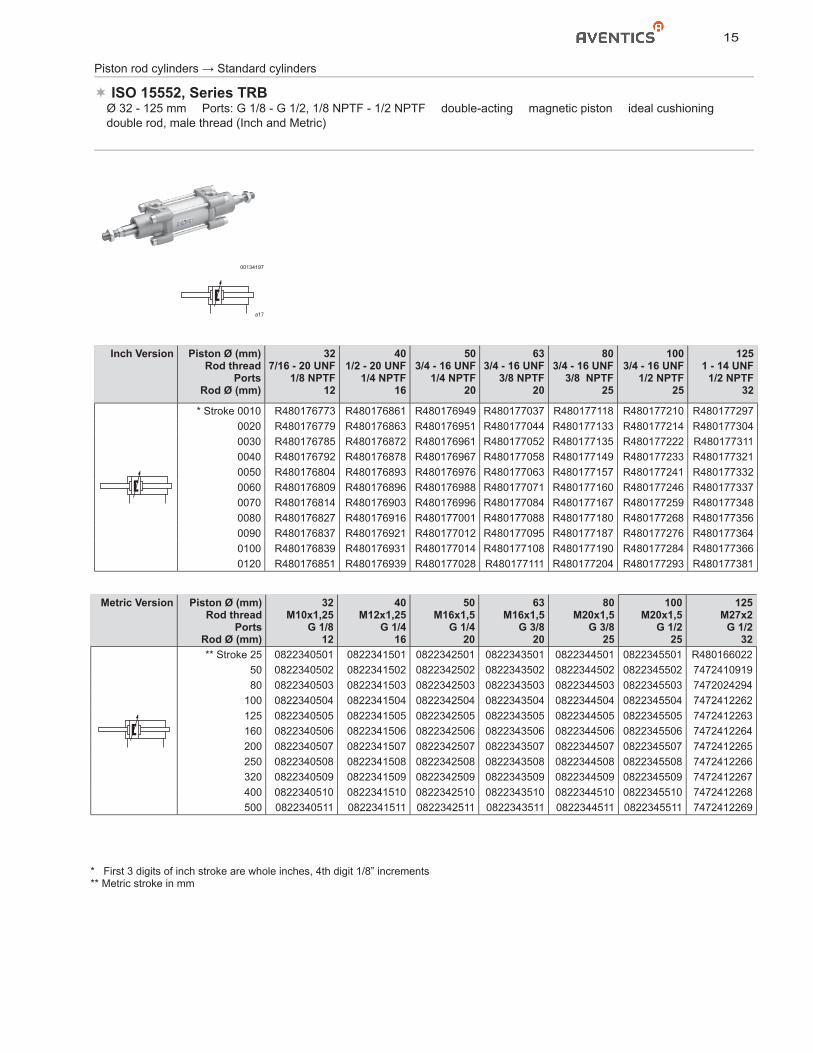
ISO 15552, Series TRB� Ø 32 - 125 mm � Ports: G 1/8 - G 1/2, 1/8 NPTF - 1/2 NPTF � double-acting � magnetic piston � ideal cushioning � double rod, male thread (Inch and Metric)
00134197
a17
Metric Version Piston Ø (mm)Rod thread
PortsRod Ø (mm)
32M10x1,25
G 1/812
40M12x1,25
G 1/416
50M16x1,5
G 1/420
63M16x1,5
G 3/820
80M20x1,5
G 3/825
100M20x1,5
G 1/225
125M27x2
G 1/232
** Stroke 25 0822340501 0822341501 0822342501 0822343501 0822344501 0822345501 R48016602250 0822340502 0822341502 0822342502 0822343502 0822344502 0822345502 747241091980 0822340503 0822341503 0822342503 0822343503 0822344503 0822345503 7472024294
100 0822340504 0822341504 0822342504 0822343504 0822344504 0822345504 7472412262125 0822340505 0822341505 0822342505 0822343505 0822344505 0822345505 7472412263160 0822340506 0822341506 0822342506 0822343506 0822344506 0822345506 7472412264200 0822340507 0822341507 0822342507 0822343507 0822344507 0822345507 7472412265250 0822340508 0822341508 0822342508 0822343508 0822344508 0822345508 7472412266320 0822340509 0822341509 0822342509 0822343509 0822344509 0822345509 7472412267400 0822340510 0822341510 0822342510 0822343510 0822344510 0822345510 7472412268500 0822340511 0822341511 0822342511 0822343511 0822344511 0822345511 7472412269
Inch Version Piston Ø (mm)Rod thread
PortsRod Ø (mm)
327/16 - 20 UNF
1/8 NPTF12
401/2 - 20 UNF
1/4 NPTF16
503/4 - 16 UNF
1/4 NPTF20
633/4 - 16 UNF
3/8 NPTF20
803/4 - 16 UNF
3/8 NPTF25
1003/4 - 16 UNF
1/2 NPTF25
1251 - 14 UNF
1/2 NPTF32
* Stroke 0010 R480176773 R480176861 R480176949 R480177037 R480177118 R480177210 R4801772970020 R480176779 R480176863 R480176951 R480177044 R480177133 R480177214 R4801773040030 R480176785 R480176872 R480176961 R480177052 R480177135 R480177222 R4801773110040 R480176792 R480176878 R480176967 R480177058 R480177149 R480177233 R4801773210050 R480176804 R480176893 R480176976 R480177063 R480177157 R480177241 R4801773320060 R480176809 R480176896 R480176988 R480177071 R480177160 R480177246 R4801773370070 R480176814 R480176903 R480176996 R480177084 R480177167 R480177259 R4801773480080 R480176827 R480176916 R480177001 R480177088 R480177180 R480177268 R4801773560090 R480176837 R480176921 R480177012 R480177095 R480177187 R480177276 R4801773640100 R480176839 R480176931 R480177014 R480177108 R480177190 R480177284 R4801773660120 R480176851 R480176939 R480177028 R480177111 R480177204 R480177293 R480177381
* First 3 digits of inch stroke are whole inches, 4th digit 1/8” increments** Metric stroke in mm
16
Piston rod cylinders → Standard cylinders
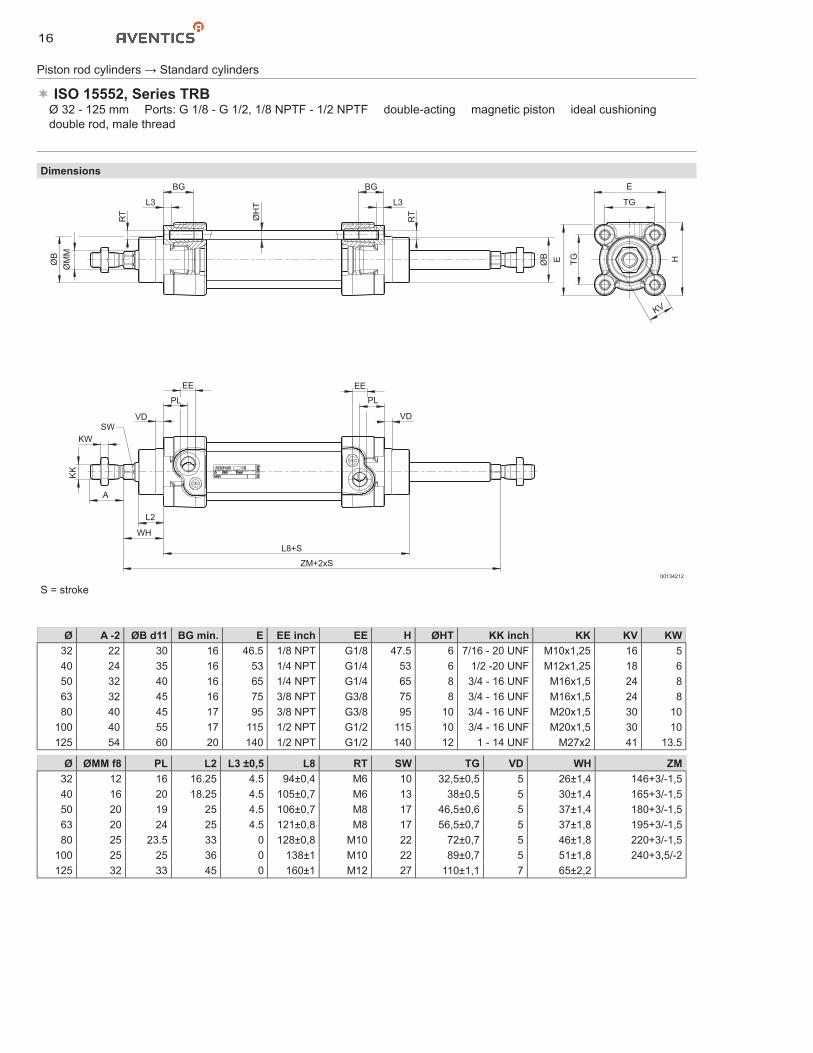
ISO 15552, Series TRB� Ø 32 - 125 mm � Ports: G 1/8 - G 1/2, 1/8 NPTF - 1/2 NPTF � double-acting � magnetic piston � ideal cushioning � double rod, male thread
DimensionsE
TG
H
KV
TGEØB
ØM
M
RT
BG
L3
ØH
T
BG
RT
L3
ØB
PL
VD
EE
L8+S
ZM+2xS
WH
L2
A
KK
KWSW
VD
PL
EE
00134212
S = stroke
Ø A -2 ØB d11 BG min. E EE inch EE H ØHT KK inch KK KV KW32 22 30 16 46.5 1/8 NPT G1/8 47.5 6 7/16 - 20 UNF M10x1,25 16 540 24 35 16 53 1/4 NPT G1/4 53 6 1/2 -20 UNF M12x1,25 18 650 32 40 16 65 1/4 NPT G1/4 65 8 3/4 - 16 UNF M16x1,5 24 863 32 45 16 75 3/8 NPT G3/8 75 8 3/4 - 16 UNF M16x1,5 24 880 40 45 17 95 3/8 NPT G3/8 95 10 3/4 - 16 UNF M20x1,5 30 10
100 40 55 17 115 1/2 NPT G1/2 115 10 3/4 - 16 UNF M20x1,5 30 10125 54 60 20 140 1/2 NPT G1/2 140 12 1 - 14 UNF M27x2 41 13.5
Ø ØMM f8 PL L2 L3 ±0,5 L8 RT SW TG VD WH ZM32 12 16 16.25 4.5 94±0,4 M6 10 32,5±0,5 5 26±1,4 146+3/-1,540 16 20 18.25 4.5 105±0,7 M6 13 38±0,5 5 30±1,4 165+3/-1,550 20 19 25 4.5 106±0,7 M8 17 46,5±0,6 5 37±1,4 180+3/-1,563 20 24 25 4.5 121±0,8 M8 17 56,5±0,7 5 37±1,8 195+3/-1,580 25 23.5 33 0 128±0,8 M10 22 72±0,7 5 46±1,8 220+3/-1,5
100 25 25 36 0 138±1 M10 22 89±0,7 5 51±1,8 240+3,5/-2125 32 33 45 0 160±1 M12 27 110±1,1 7 65±2,2
17
Piston rod cylinders → Standard cylinders
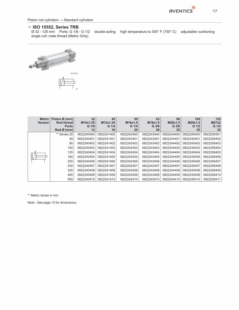
ISO 15552, Series TRB� Ø 32 - 125 mm � Ports: G 1/8 - G 1/2 � double-acting � high temperature to 300° F (150° C) � adjustable cushioning � single rod: male thread (Metric Only)
00134195
a5
MetricVersion
Piston Ø (mm)Rod thread
PortsRod Ø (mm)
32M10x1,25
G 1/812
40M12x1,25
G 1/416
50M16x1,5
G 1/420
63M16x1,5
G 3/820
80M20x1,5
G 3/825
100M20x1,5
G 1/225
125M27x2
G 1/232
** Stroke 25 0822240400 0822241400 0822242400 0822243400 0822244400 0822245400 082220640150 0822240401 0822241401 0822242401 0822243401 0822244401 0822245401 082220640280 0822240402 0822241402 0822242402 0822243402 0822244402 0822245402 0822206403
100 0822240403 0822241403 0822242403 0822243403 0822244403 0822245403 0822206404125 0822240404 0822241404 0822242404 0822243404 0822244404 0822245404 0822206405160 0822240405 0822241405 0822242405 0822243405 0822244405 0822245405 0822206406200 0822240406 0822241406 0822242406 0822243406 0822244406 0822245406 0822206407250 0822240407 0822241407 0822242407 0822243407 0822244407 0822245407 0822206408320 0822240408 0822241408 0822242408 0822243408 0822244408 0822245408 0822206409400 0822240409 0822241409 0822242409 0822243409 0822244409 0822245409 0822206410500 0822240410 0822241410 0822242410 0822243410 0822244410 0822245410 0822206411
** Metric stroke in mm
Note - See page 13 for dimensions.
18
Dimensions
TM
XVmax+S
TK
ØTD
TM
XV+S/2
TL
PL
VA
EE
WH
L2
L8 + S
KK
KW
A
SWVD
PL
EE
XVmin
ØB
ØM
M
RT
BG
L3
ØB
A
BG
RTØH
T L3
E
TG
E HKV
TG
HW
00134213
S = stroke
Piston rod cylinders → Standard cylinders
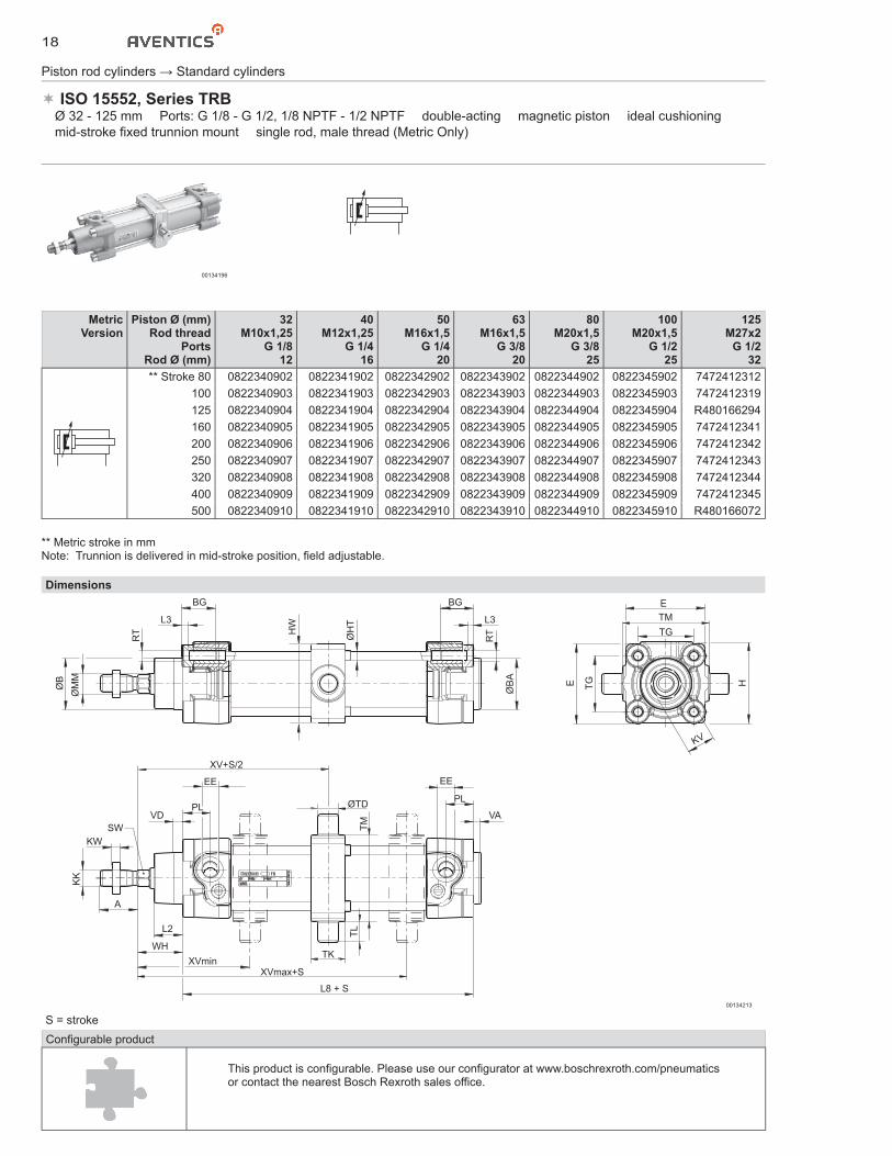
ISO 15552, Series TRB� Ø 32 - 125 mm � Ports: G 1/8 - G 1/2, 1/8 NPTF - 1/2 NPTF � double-acting � magnetic piston � ideal cushioning � mid-stroke fixed trunnion mount � single rod, male thread (Metric Only)
00134196
MetricVersion
Piston Ø (mm)Rod thread
PortsRod Ø (mm)
32M10x1,25
G 1/812
40M12x1,25
G 1/416
50M16x1,5
G 1/420
63M16x1,5
G 3/820
80M20x1,5
G 3/825
100M20x1,5
G 1/225
125M27x2
G 1/232
** Stroke 80 0822340902 0822341902 0822342902 0822343902 0822344902 0822345902 7472412312100 0822340903 0822341903 0822342903 0822343903 0822344903 0822345903 7472412319125 0822340904 0822341904 0822342904 0822343904 0822344904 0822345904 R480166294160 0822340905 0822341905 0822342905 0822343905 0822344905 0822345905 7472412341200 0822340906 0822341906 0822342906 0822343906 0822344906 0822345906 7472412342250 0822340907 0822341907 0822342907 0822343907 0822344907 0822345907 7472412343320 0822340908 0822341908 0822342908 0822343908 0822344908 0822345908 7472412344400 0822340909 0822341909 0822342909 0822343909 0822344909 0822345909 7472412345500 0822340910 0822341910 0822342910 0822343910 0822344910 0822345910 R480166072
Configurable product
This product is configurable. Please use our configurator at www.boschrexroth.com/pneumatics or contact the nearest Bosch Rexroth sales office.
** Metric stroke in mmNote: Trunnion is delivered in mid-stroke position, field adjustable.
19
Piston rod cylinders → Standard cylinders
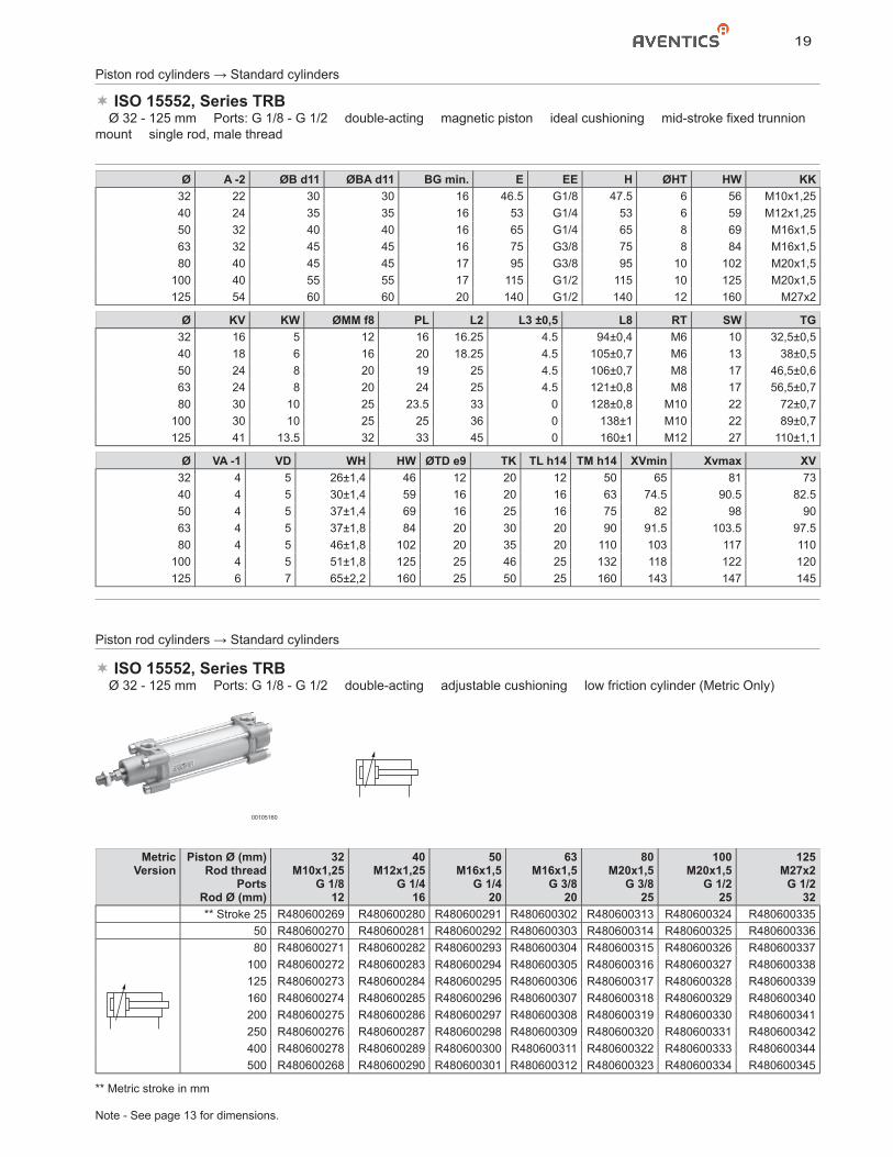
ISO 15552, Series TRB� Ø 32 - 125 mm � Ports: G 1/8 - G 1/2 � double-acting � magnetic piston � ideal cushioning � mid-stroke fixed trunnion mount � single rod, male thread
Ø A -2 ØB d11 ØBA d11 BG min. E EE H ØHT HW KK32 22 30 30 16 46.5 G1/8 47.5 6 56 M10x1,2540 24 35 35 16 53 G1/4 53 6 59 M12x1,2550 32 40 40 16 65 G1/4 65 8 69 M16x1,563 32 45 45 16 75 G3/8 75 8 84 M16x1,580 40 45 45 17 95 G3/8 95 10 102 M20x1,5
100 40 55 55 17 115 G1/2 115 10 125 M20x1,5125 54 60 60 20 140 G1/2 140 12 160 M27x2
Ø KV KW ØMM f8 PL L2 L3 ±0,5 L8 RT SW TG32 16 5 12 16 16.25 4.5 94±0,4 M6 10 32,5±0,540 18 6 16 20 18.25 4.5 105±0,7 M6 13 38±0,550 24 8 20 19 25 4.5 106±0,7 M8 17 46,5±0,663 24 8 20 24 25 4.5 121±0,8 M8 17 56,5±0,780 30 10 25 23.5 33 0 128±0,8 M10 22 72±0,7
100 30 10 25 25 36 0 138±1 M10 22 89±0,7125 41 13.5 32 33 45 0 160±1 M12 27 110±1,1
Ø VA -1 VD WH HW ØTD e9 TK TL h14 TM h14 XVmin Xvmax XV32 4 5 26±1,4 46 12 20 12 50 65 81 7340 4 5 30±1,4 59 16 20 16 63 74.5 90.5 82.550 4 5 37±1,4 69 16 25 16 75 82 98 9063 4 5 37±1,8 84 20 30 20 90 91.5 103.5 97.580 4 5 46±1,8 102 20 35 20 110 103 117 110
100 4 5 51±1,8 125 25 46 25 132 118 122 120125 6 7 65±2,2 160 25 50 25 160 143 147 145
Piston rod cylinders → Standard cylinders
ISO 15552, Series TRB� Ø 32 - 125 mm � Ports: G 1/8 - G 1/2 � double-acting � adjustable cushioning � low friction cylinder (Metric Only)
00105160
MetricVersion
Piston Ø (mm)Rod thread
PortsRod Ø (mm)
32M10x1,25
G 1/812
40M12x1,25
G 1/416
50M16x1,5
G 1/420
63M16x1,5
G 3/820
80M20x1,5
G 3/825
100M20x1,5
G 1/225
125M27x2
G 1/232
** Stroke 25 R480600269 R480600280 R480600291 R480600302 R480600313 R480600324 R48060033550 R480600270 R480600281 R480600292 R480600303 R480600314 R480600325 R48060033680 R480600271 R480600282 R480600293 R480600304 R480600315 R480600326 R480600337
100 R480600272 R480600283 R480600294 R480600305 R480600316 R480600327 R480600338125 R480600273 R480600284 R480600295 R480600306 R480600317 R480600328 R480600339160 R480600274 R480600285 R480600296 R480600307 R480600318 R480600329 R480600340200 R480600275 R480600286 R480600297 R480600308 R480600319 R480600330 R480600341250 R480600276 R480600287 R480600298 R480600309 R480600320 R480600331 R480600342400 R480600278 R480600289 R480600300 R480600311 R480600322 R480600333 R480600344500 R480600268 R480600290 R480600301 R480600312 R480600323 R480600334 R480600345
** Metric stroke in mm
Note - See page 13 for dimensions.
20
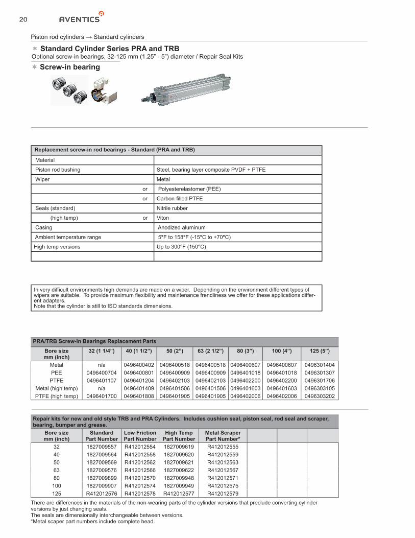
Replacement screw-in rod bearings - Standard (PRA and TRB)
Material
Piston rod bushing Steel, bearing layer composite PVDF + PTFE
Wiper Metal
or Polyesterelastomer (PEE)
or Carbon-filled PTFE
Seals (standard) Nitrile rubber
(high temp) or Viton
Casing Anodized aluminum
Ambient temperature range 5°F to 158°F (-15°C to +70°C)
High temp versions Up to 300°F (150°C)
Piston rod cylinders → Standard cylinders
PRA/TRB Screw-in Bearings Replacement Parts
Bore sizemm (inch)
32 (1 1/4”) 40 (1 1/2”) 50 (2”) 63 (2 1/2”) 80 (3”) 100 (4”) 125 (5”)
Metal n/a 0496400402 0496400518 0496400518 0496400607 0496400607 0496301404PEE 0496400704 0496400801 0496400909 0496400909 0496401018 0496401018 0496301307PTFE 0496401107 0496401204 0496402103 0496402103 0496402200 0496402200 0496301706
Metal (high temp) n/a 0496401409 0496401506 0496401506 0496401603 0496401603 0496303105PTFE (high temp) 0496401700 0496401808 0496401905 0496401905 0496402006 0496402006 0496303202
In very difficult environments high demands are made on a wiper. Depending on the environment different types of wipers are suitable. To provide maximum flexibility and maintenance frendliness we offer for these applications differ-ent adapters.Note that the cylinder is still to ISO standards dimensions.
Standard Cylinder Series PRA and TRBOptional screw-in bearings, 32-125 mm (1.25” - 5”) diameter / Repair Seal Kits
Screw-in bearing
Repair kits for new and old style TRB and PRA Cylinders. Includes cushion seal, piston seal, rod seal and scraper, bearing, bumper and grease.
Bore sizemm (inch)
Standard Part Number
Low Friction Part Number
High Temp Part Number
Metal ScraperPart Number*
32 1827009557 R412012554 1827009619 R41201255540 1827009564 R412012558 1827009620 R41201255950 1827009569 R412012562 1827009621 R41201256363 1827009576 R412012566 1827009622 R41201256780 1827009899 R412012570 1827009948 R412012571
100 1827009907 R412012574 1827009949 R412012575125 R412012576 R412012578 R412012577 R412012579
There are differences in the materials of the non-wearing parts of the cylinder versions that preclude converting cylinderversions by just changing seals.The seals are dimensionally interchangeable between versions.*Metal scaper part numbers include complete head.
21
Piston rod cylinders → Standard cylinders
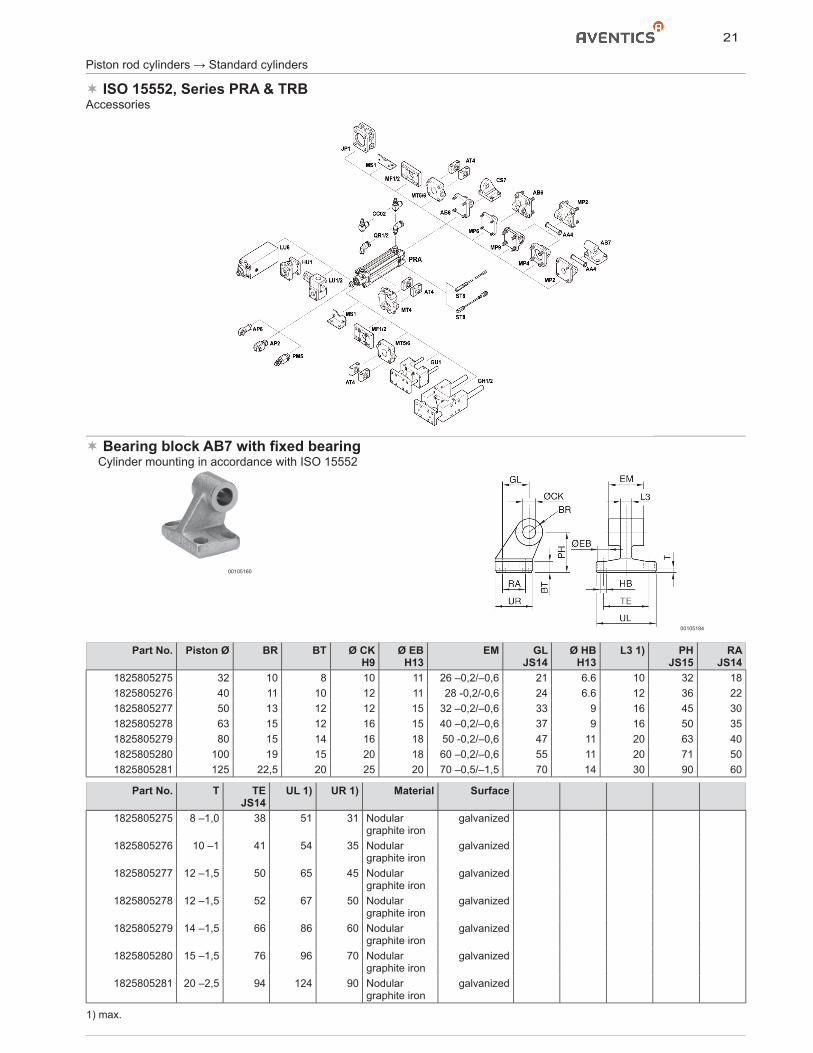
ISO 15552, Series PRA & TRBAccessories
Bearing block AB7 with fixed bearing� Cylinder mounting in accordance with ISO 15552
00105160
00105184
Part No. Piston Ø BR BT Ø CK H9
Ø EB H13
EM GL JS14
Ø HB H13
L3 1) PH JS15
RA JS14
1825805275 32 10 8 10 11 26 –0,2/–0,6 21 6.6 10 32 181825805276 40 11 10 12 11 28 -0,2/-0,6 24 6.6 12 36 221825805277 50 13 12 12 15 32 –0,2/–0,6 33 9 16 45 301825805278 63 15 12 16 15 40 –0,2/–0,6 37 9 16 50 351825805279 80 15 14 16 18 50 -0,2/–0,6 47 11 20 63 401825805280 100 19 15 20 18 60 –0,2/–0,6 55 11 20 71 501825805281 125 22,5 20 25 20 70 –0,5/–1,5 70 14 30 90 60
Part No. T TE JS14
UL 1) UR 1) Material Surface
1825805275 8 –1,0 38 51 31 Nodular graphite iron
galvanized
1825805276 10 –1 41 54 35 Nodular graphite iron
galvanized
1825805277 12 –1,5 50 65 45 Nodular graphite iron
galvanized
1825805278 12 –1,5 52 67 50 Nodular graphite iron
galvanized
1825805279 14 –1,5 66 86 60 Nodular graphite iron
galvanized
1825805280 15 –1,5 76 96 70 Nodular graphite iron
galvanized
1825805281 20 –2,5 94 124 90 Nodular graphite iron
galvanized
1) max.
22
Piston rod cylinders → Standard cylinders
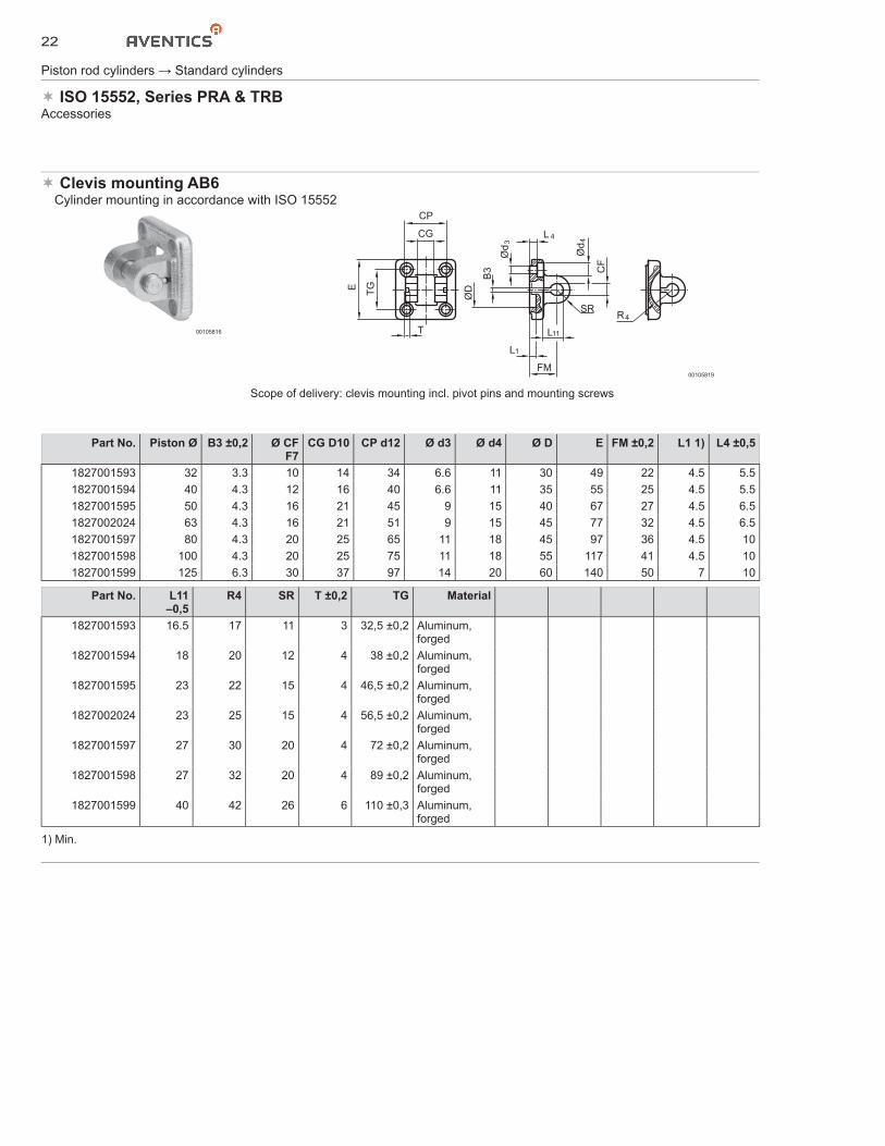
ISO 15552, Series PRA & TRBAccessories
Clevis mounting AB6� Cylinder mounting in accordance with ISO 15552
00105816
4R
T
TGE
CP
CG
CF
SR
FM
L
L
L
B3
ØD
Ød
3
4
1
11
Ød
4
00105819
Scope of delivery: clevis mounting incl. pivot pins and mounting screws
Part No. Piston Ø B3 ±0,2 Ø CF F7
CG D10 CP d12 Ø d3 Ø d4 Ø D E FM ±0,2 L1 1) L4 ±0,5
1827001593 32 3.3 10 14 34 6.6 11 30 49 22 4.5 5.51827001594 40 4.3 12 16 40 6.6 11 35 55 25 4.5 5.51827001595 50 4.3 16 21 45 9 15 40 67 27 4.5 6.51827002024 63 4.3 16 21 51 9 15 45 77 32 4.5 6.51827001597 80 4.3 20 25 65 11 18 45 97 36 4.5 101827001598 100 4.3 20 25 75 11 18 55 117 41 4.5 101827001599 125 6.3 30 37 97 14 20 60 140 50 7 10
Part No. L11 –0,5
R4 SR T ±0,2 TG Material
1827001593 16.5 17 11 3 32,5 ±0,2 Aluminum, forged
1827001594 18 20 12 4 38 ±0,2 Aluminum, forged
1827001595 23 22 15 4 46,5 ±0,2 Aluminum, forged
1827002024 23 25 15 4 56,5 ±0,2 Aluminum, forged
1827001597 27 30 20 4 72 ±0,2 Aluminum, forged
1827001598 27 32 20 4 89 ±0,2 Aluminum, forged
1827001599 40 42 26 6 110 ±0,3 Aluminum, forged
1) Min.
23
Piston rod cylinders → Standard cylinders
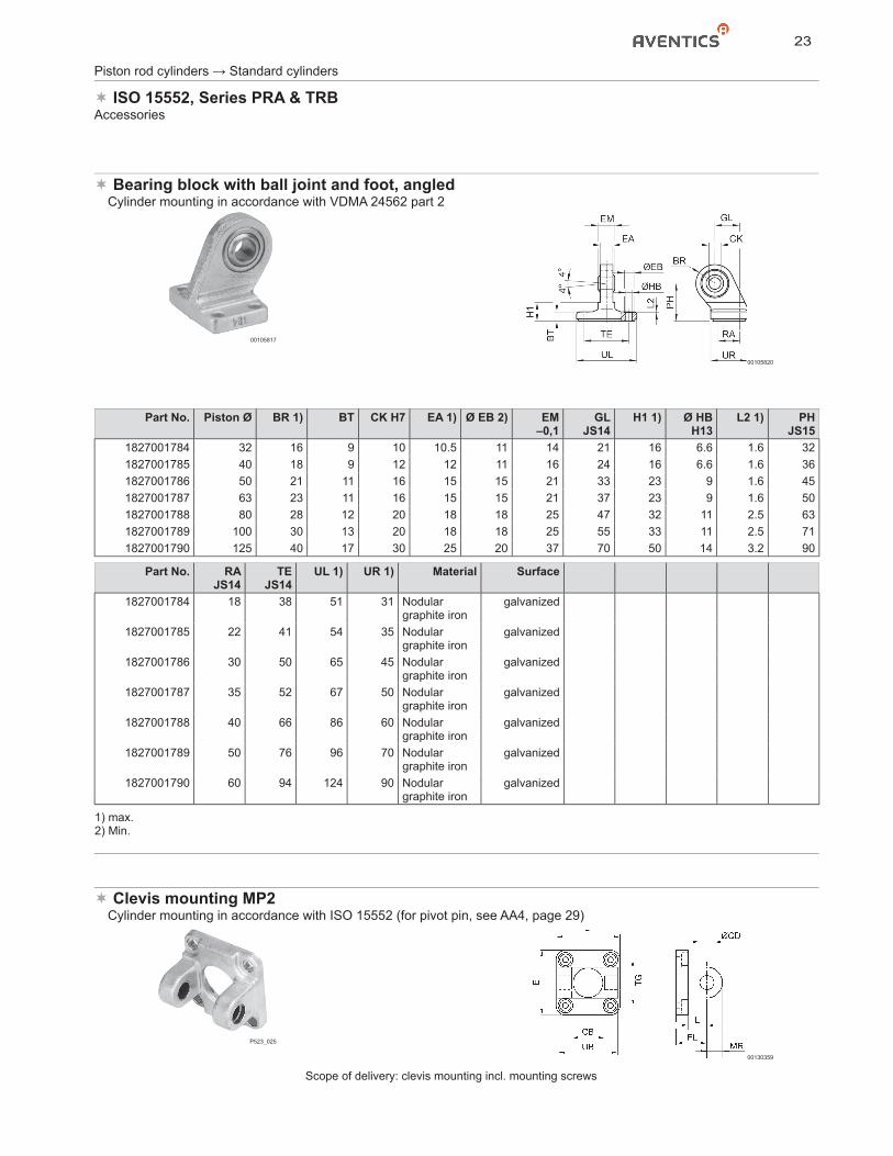
ISO 15552, Series PRA & TRBAccessories
Bearing block with ball joint and foot, angled� Cylinder mounting in accordance with VDMA 24562 part 2
00105817
00105820
Part No. Piston Ø BR 1) BT CK H7 EA 1) Ø EB 2) EM –0,1
GL JS14
H1 1) Ø HB H13
L2 1) PH JS15
1827001784 32 16 9 10 10.5 11 14 21 16 6.6 1.6 321827001785 40 18 9 12 12 11 16 24 16 6.6 1.6 361827001786 50 21 11 16 15 15 21 33 23 9 1.6 451827001787 63 23 11 16 15 15 21 37 23 9 1.6 501827001788 80 28 12 20 18 18 25 47 32 11 2.5 631827001789 100 30 13 20 18 18 25 55 33 11 2.5 711827001790 125 40 17 30 25 20 37 70 50 14 3.2 90
Part No. RA JS14
TE JS14
UL 1) UR 1) Material Surface
1827001784 18 38 51 31 Nodular graphite iron
galvanized
1827001785 22 41 54 35 Nodular graphite iron
galvanized
1827001786 30 50 65 45 Nodular graphite iron
galvanized
1827001787 35 52 67 50 Nodular graphite iron
galvanized
1827001788 40 66 86 60 Nodular graphite iron
galvanized
1827001789 50 76 96 70 Nodular graphite iron
galvanized
1827001790 60 94 124 90 Nodular graphite iron
galvanized
1) max.2) Min.
Clevis mounting MP2� Cylinder mounting in accordance with ISO 15552 (for pivot pin, see AA4, page 29)
P523_025
00130359
Scope of delivery: clevis mounting incl. mounting screws
24
Piston rod cylinders → Standard cylinders
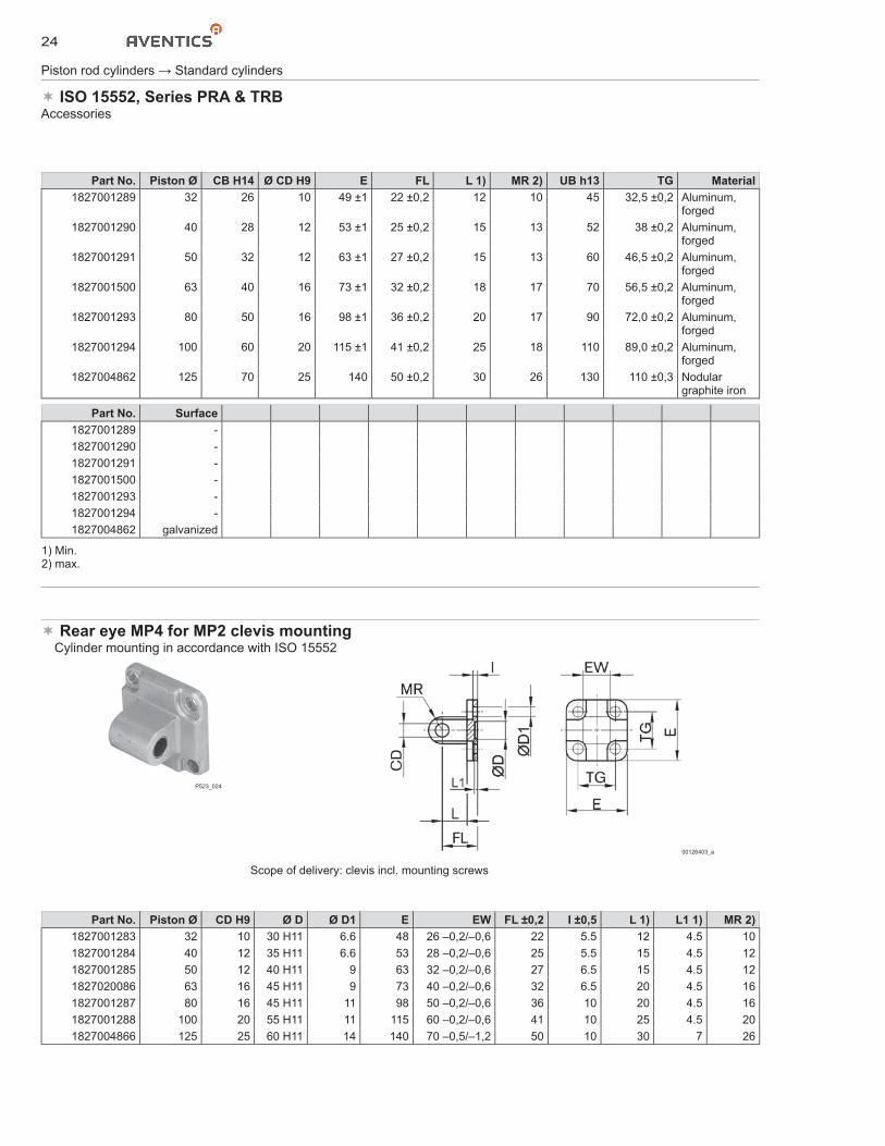
ISO 15552, Series PRA & TRBAccessories
Part No. Piston Ø CB H14 Ø CD H9 E FL L 1) MR 2) UB h13 TG Material1827001289 32 26 10 49 ±1 22 ±0,2 12 10 45 32,5 ±0,2 Aluminum,
forged1827001290 40 28 12 53 ±1 25 ±0,2 15 13 52 38 ±0,2 Aluminum,
forged1827001291 50 32 12 63 ±1 27 ±0,2 15 13 60 46,5 ±0,2 Aluminum,
forged1827001500 63 40 16 73 ±1 32 ±0,2 18 17 70 56,5 ±0,2 Aluminum,
forged1827001293 80 50 16 98 ±1 36 ±0,2 20 17 90 72,0 ±0,2 Aluminum,
forged1827001294 100 60 20 115 ±1 41 ±0,2 25 18 110 89,0 ±0,2 Aluminum,
forged1827004862 125 70 25 140 50 ±0,2 30 26 130 110 ±0,3 Nodular
graphite iron
Part No. Surface1827001289 -1827001290 -1827001291 -1827001500 -1827001293 -1827001294 -1827004862 galvanized
1) Min.2) max.
Rear eye MP4 for MP2 clevis mounting� Cylinder mounting in accordance with ISO 15552
P523_024
00126403_a
Scope of delivery: clevis incl. mounting screws
Part No. Piston Ø CD H9 Ø D Ø D1 E EW FL ±0,2 I ±0,5 L 1) L1 1) MR 2)1827001283 32 10 30 H11 6.6 48 26 –0,2/–0,6 22 5.5 12 4.5 101827001284 40 12 35 H11 6.6 53 28 –0,2/–0,6 25 5.5 15 4.5 121827001285 50 12 40 H11 9 63 32 –0,2/–0,6 27 6.5 15 4.5 121827020086 63 16 45 H11 9 73 40 –0,2/–0,6 32 6.5 20 4.5 161827001287 80 16 45 H11 11 98 50 –0,2/–0,6 36 10 20 4.5 161827001288 100 20 55 H11 11 115 60 –0,2/–0,6 41 10 25 4.5 201827004866 125 25 60 H11 14 140 70 –0,5/–1,2 50 10 30 7 26
25
Piston rod cylinders → Standard cylinders
ISO 15552, Series PRA & TRBAccessories
Part No. TG Material Surface1827001283 32,5 ±0,2 Aluminum,
forged-
1827001284 38 ±0,2 Aluminum, forged
-
1827001285 46,5 ±0,2 Aluminum, forged
-
1827020086 56,5 ±0,2 Aluminum, forged
-
1827001287 72 ±0,2 Aluminum, forged
-
1827001288 89 ±0,2 Aluminum, forged
-
1827004866 110 ±0,3 Nodular graphite iron
galvanized
1) Min.2) max.
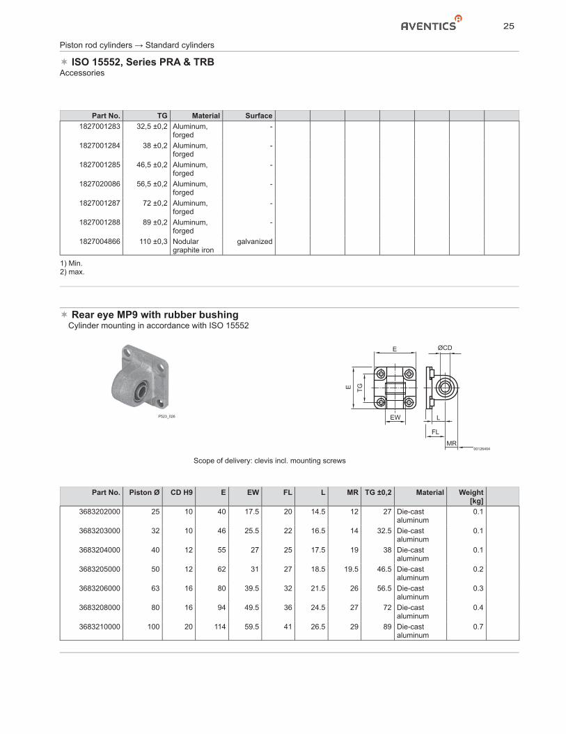
Rear eye MP9 with rubber bushing� Cylinder mounting in accordance with ISO 15552
P523_026
E
MR
L
FL
ØCD
EW
E TG
00126404
Scope of delivery: clevis incl. mounting screws
Part No. Piston Ø CD H9 E EW FL L MR TG ±0,2 Material Weight[kg]
3683202000 25 10 40 17.5 20 14.5 12 27 Die-cast aluminum
0.1
3683203000 32 10 46 25.5 22 16.5 14 32.5 Die-cast aluminum
0.1
3683204000 40 12 55 27 25 17.5 19 38 Die-cast aluminum
0.1
3683205000 50 12 62 31 27 18.5 19.5 46.5 Die-cast aluminum
0.2
3683206000 63 16 80 39.5 32 21.5 26 56.5 Die-cast aluminum
0.3
3683208000 80 16 94 49.5 36 24.5 27 72 Die-cast aluminum
0.4
3683210000 100 20 114 59.5 41 26.5 29 89 Die-cast aluminum
0.7
26
Piston rod cylinders → Standard cylinders
ISO 15552, Series PRA & TRBAccessories
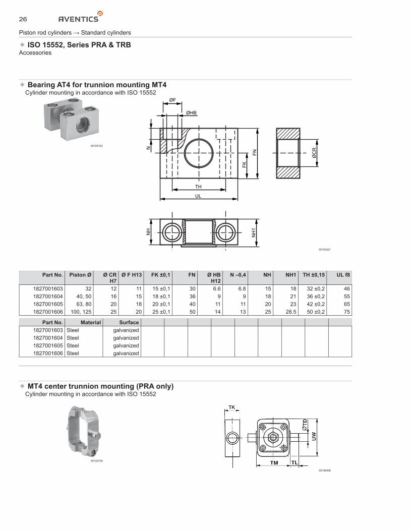
Bearing AT4 for trunnion mounting MT4� Cylinder mounting in accordance with ISO 15552
00105163
ØF
ØHB
UL
TH
NN
H
NH
1
FK
FN
ØC
R
00105221
Part No. Piston Ø Ø CR H7
Ø F H13 FK ±0,1 FN Ø HB H12
N –0,4 NH NH1 TH ±0,15 UL f8
1827001603 32 12 11 15 ±0,1 30 6.6 6.8 15 18 32 ±0,2 461827001604 40, 50 16 15 18 ±0,1 36 9 9 18 21 36 ±0,2 551827001605 63, 80 20 18 20 ±0,1 40 11 11 20 23 42 ±0,2 651827001606 100, 125 25 20 25 ±0,1 50 14 13 25 28.5 50 ±0,2 75
Part No. Material Surface1827001603 Steel galvanized1827001604 Steel galvanized1827001605 Steel galvanized1827001606 Steel galvanized
MT4 center trunnion mounting (PRA only)� Cylinder mounting in accordance with ISO 15552
00122726
00126406
27
Piston rod cylinders → Standard cylinders
ISO 15552, Series PRA & TRBAccessories
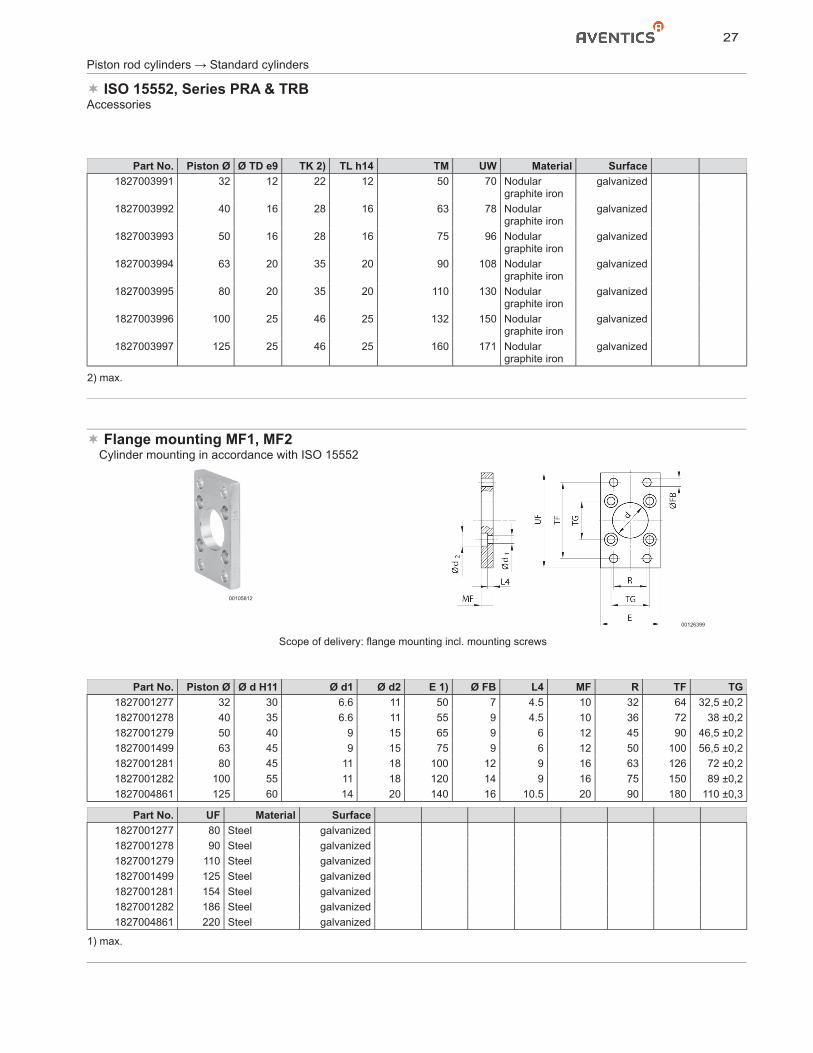
Part No. Piston Ø Ø TD e9 TK 2) TL h14 TM UW Material Surface1827003991 32 12 22 12 50 70 Nodular
graphite irongalvanized
1827003992 40 16 28 16 63 78 Nodular graphite iron
galvanized
1827003993 50 16 28 16 75 96 Nodular graphite iron
galvanized
1827003994 63 20 35 20 90 108 Nodular graphite iron
galvanized
1827003995 80 20 35 20 110 130 Nodular graphite iron
galvanized
1827003996 100 25 46 25 132 150 Nodular graphite iron
galvanized
1827003997 125 25 46 25 160 171 Nodular graphite iron
galvanized
2) max.
Flange mounting MF1, MF2� Cylinder mounting in accordance with ISO 15552
00105812
00126399
Scope of delivery: flange mounting incl. mounting screws
Part No. Piston Ø Ø d H11 Ø d1 Ø d2 E 1) Ø FB L4 MF R TF TG1827001277 32 30 6.6 11 50 7 4.5 10 32 64 32,5 ±0,21827001278 40 35 6.6 11 55 9 4.5 10 36 72 38 ±0,21827001279 50 40 9 15 65 9 6 12 45 90 46,5 ±0,21827001499 63 45 9 15 75 9 6 12 50 100 56,5 ±0,21827001281 80 45 11 18 100 12 9 16 63 126 72 ±0,21827001282 100 55 11 18 120 14 9 16 75 150 89 ±0,21827004861 125 60 14 20 140 16 10.5 20 90 180 110 ±0,3
Part No. UF Material Surface1827001277 80 Steel galvanized1827001278 90 Steel galvanized1827001279 110 Steel galvanized1827001499 125 Steel galvanized1827001281 154 Steel galvanized1827001282 186 Steel galvanized1827004861 220 Steel galvanized
1) max.
28
Piston rod cylinders → Standard cylinders
ISO 15552, Series PRA & TRBAccessories
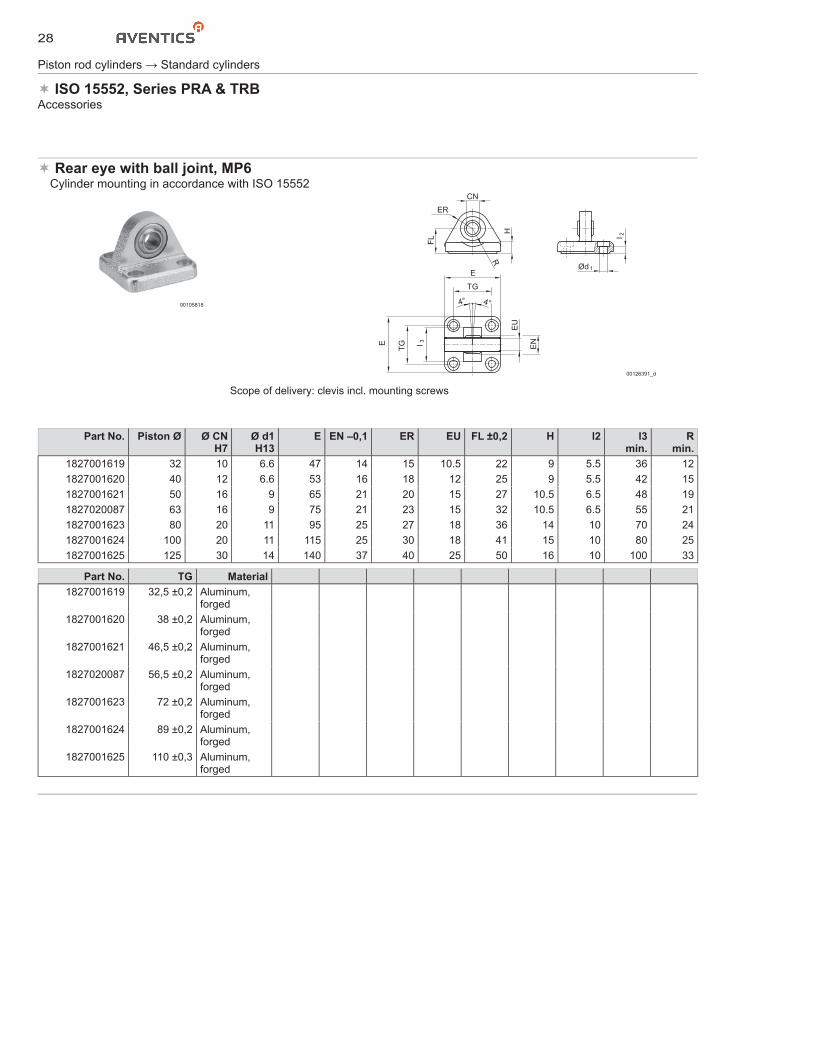
Rear eye with ball joint, MP6� Cylinder mounting in accordance with ISO 15552
00105818
EN
EU
E
TG
E
I 3
TG
4° 4°
ER
FL
CN
H
R
I 2
Ød 1
00126391_d
Scope of delivery: clevis incl. mounting screws
Part No. Piston Ø Ø CN H7
Ø d1 H13
E EN –0,1 ER EU FL ±0,2 H l2 l3 min.
R min.
1827001619 32 10 6.6 47 14 15 10.5 22 9 5.5 36 121827001620 40 12 6.6 53 16 18 12 25 9 5.5 42 151827001621 50 16 9 65 21 20 15 27 10.5 6.5 48 191827020087 63 16 9 75 21 23 15 32 10.5 6.5 55 211827001623 80 20 11 95 25 27 18 36 14 10 70 241827001624 100 20 11 115 25 30 18 41 15 10 80 251827001625 125 30 14 140 37 40 25 50 16 10 100 33
Part No. TG Material1827001619 32,5 ±0,2 Aluminum,
forged1827001620 38 ±0,2 Aluminum,
forged1827001621 46,5 ±0,2 Aluminum,
forged1827020087 56,5 ±0,2 Aluminum,
forged1827001623 72 ±0,2 Aluminum,
forged1827001624 89 ±0,2 Aluminum,
forged1827001625 110 ±0,3 Aluminum,
forged
29
Piston rod cylinders → Standard cylinders
ISO 15552, Series PRA & TRBAccessories
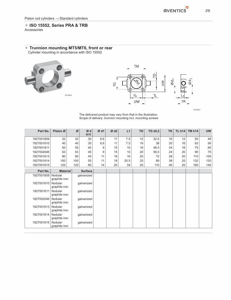
Trunnion mounting MT5/MT6, front or rear� Cylinder mounting in accordance with ISO 15552
00128925
00126407
The delivered product may vary from that in the illustration.Scope of delivery: trunnion mounting incl. mounting screws
Part No. Piston Ø Ø Ø d H11
Ø d1 Ø d2 L1 TD TG ±0,2 TK TL h14 TM h14 UW
1827001609 32 32 30 6.6 11 7.5 12 32.5 16 12 50 481827001610 40 40 35 6.6 11 7.5 16 38 20 16 63 561827001611 50 50 40 9 15 10 16 46.5 24 16 75 651827002046 63 63 45 9 15 10 20 56.5 24 20 90 751827001613 80 80 45 11 18 16 20 72 28 20 110 1001827001614 100 100 55 11 18 25.5 25 89 38 25 132 1201827001615 125 125 60 14 20 34 25 110 46 25 160 145
Part No. Material Surface1827001609 Nodular
graphite irongalvanized
1827001610 Nodular graphite iron
galvanized
1827001611 Nodular graphite iron
galvanized
1827002046 Nodular graphite iron
galvanized
1827001613 Nodular graphite iron
galvanized
1827001614 Nodular graphite iron
galvanized
1827001615 Nodular graphite iron
galvanized
30
Piston rod cylinders → Standard cylinders
ISO 15552, Series PRA & TRBAccessories
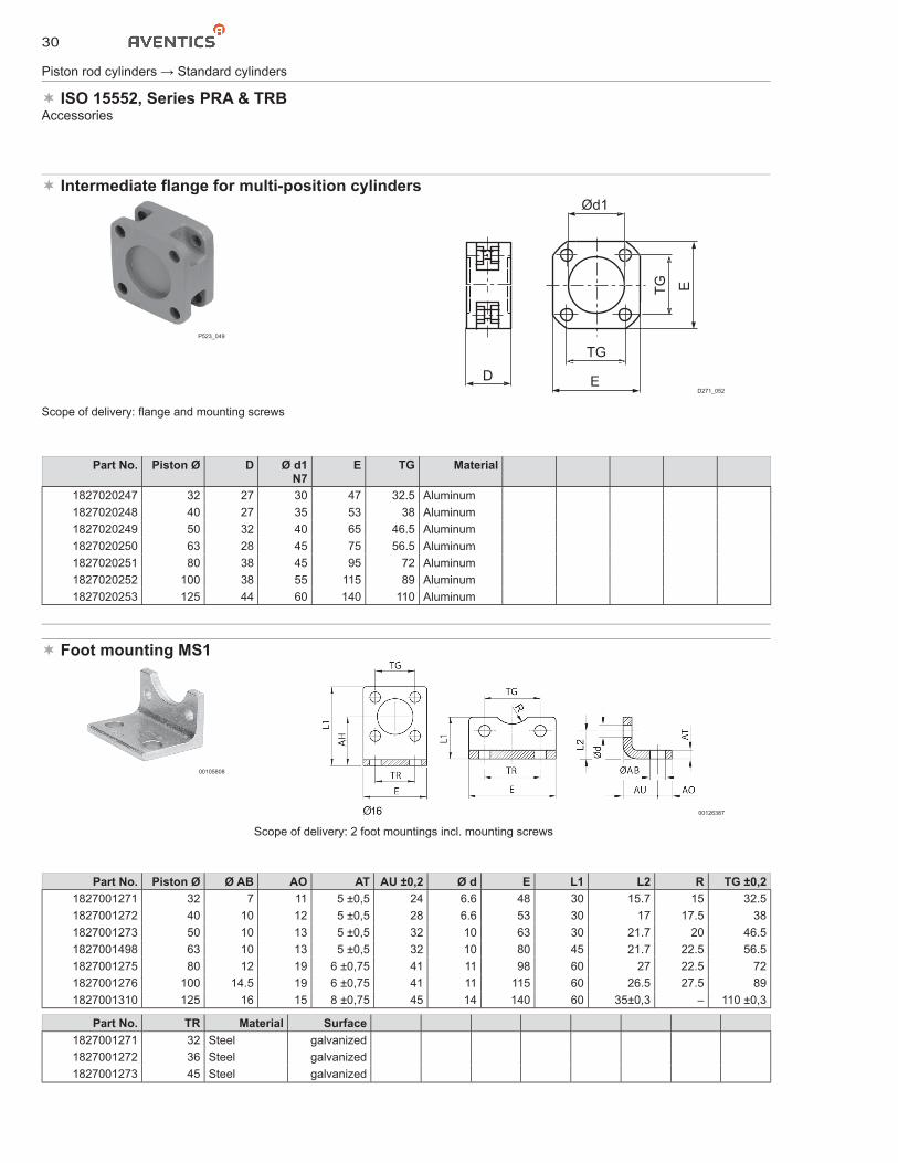
Intermediate flange for multi-position cylinders
P523_049
D
Ød1
TG
E
TG E
D271_052
Part No. Piston Ø D Ø d1N7
E TG Material
1827020247 32 27 30 47 32.5 Aluminum1827020248 40 27 35 53 38 Aluminum1827020249 50 32 40 65 46.5 Aluminum1827020250 63 28 45 75 56.5 Aluminum1827020251 80 38 45 95 72 Aluminum1827020252 100 38 55 115 89 Aluminum1827020253 125 44 60 140 110 Aluminum
Foot mounting MS1
00105808
00126387
Scope of delivery: 2 foot mountings incl. mounting screws
Part No. Piston Ø Ø AB AO AT AU ±0,2 Ø d E L1 L2 R TG ±0,21827001271 32 7 11 5 ±0,5 24 6.6 48 30 15.7 15 32.51827001272 40 10 12 5 ±0,5 28 6.6 53 30 17 17.5 381827001273 50 10 13 5 ±0,5 32 10 63 30 21.7 20 46.51827001498 63 10 13 5 ±0,5 32 10 80 45 21.7 22.5 56.51827001275 80 12 19 6 ±0,75 41 11 98 60 27 22.5 721827001276 100 14.5 19 6 ±0,75 41 11 115 60 26.5 27.5 891827001310 125 16 15 8 ±0,75 45 14 140 60 35±0,3 – 110 ±0,3
Part No. TR Material Surface1827001271 32 Steel galvanized1827001272 36 Steel galvanized1827001273 45 Steel galvanized
Scope of delivery: flange and mounting screws
31
Piston rod cylinders → Standard cylinders
ISO 15552, Series PRA & TRBAccessories
Part No. TR Material Surface1827001498 50 Steel galvanized1827001275 63 Steel galvanized1827001276 75 Steel galvanized1827001310 90 Steel galvanized
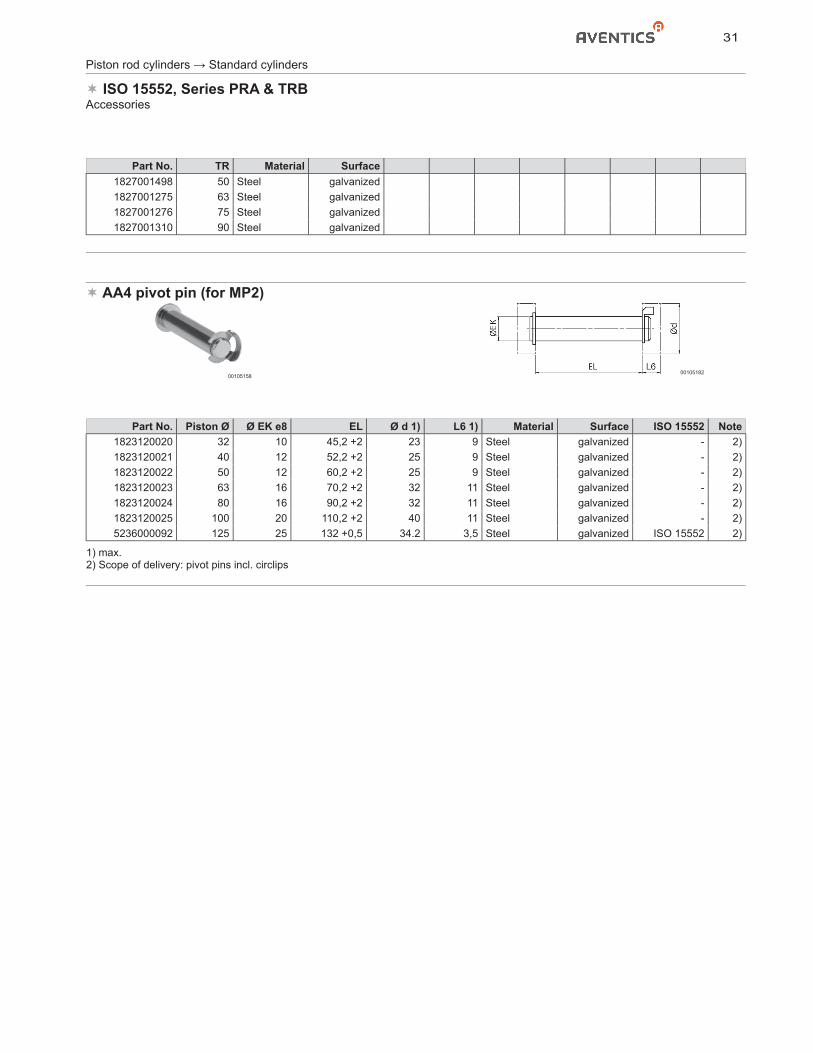
AA4 pivot pin (for MP2)
0010515800105182
Part No. Piston Ø Ø EK e8 EL Ø d 1) L6 1) Material Surface ISO 15552 Note1823120020 32 10 45,2 +2 23 9 Steel galvanized - 2)1823120021 40 12 52,2 +2 25 9 Steel galvanized - 2)1823120022 50 12 60,2 +2 25 9 Steel galvanized - 2)1823120023 63 16 70,2 +2 32 11 Steel galvanized - 2)1823120024 80 16 90,2 +2 32 11 Steel galvanized - 2)1823120025 100 20 110,2 +2 40 11 Steel galvanized - 2)5236000092 125 25 132 +0,5 34.2 3,5 Steel galvanized ISO 15552 2)
1) max.2) Scope of delivery: pivot pins incl. circlips
32
Piston rod cylinders → Standard cylinders
ISO 15552, Series PRA & TRBAccessories
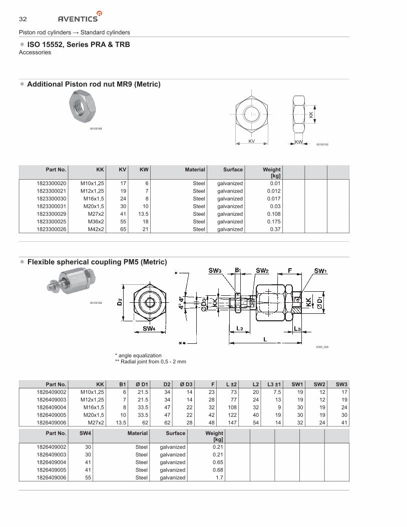
Additional Piston rod nut MR9 (Metric)
00105168
KW
KK
KV00105192
Part No. KK KV KW Material Surface Weight[kg]
1823300020 M10x1,25 17 6 Steel galvanized 0.011823300021 M12x1,25 19 7 Steel galvanized 0.0121823300030 M16x1,5 24 8 Steel galvanized 0.0171823300031 M20x1,5 30 10 Steel galvanized 0.031823300029 M27x2 41 13.5 Steel galvanized 0.1081823300025 M36x2 55 18 Steel galvanized 0.1751823300026 M42x2 65 21 Steel galvanized 0.37
Flexible spherical coupling PM5 (Metric)
00105169
D300_029
* angle equalization** Radial joint from 0,5 - 2 mm
Part No. KK B1 Ø D1 D2 Ø D3 F L ±2 L2 L3 ±1 SW1 SW2 SW31826409002 M10x1,25 6 21.5 34 14 23 73 20 7.5 19 12 171826409003 M12x1,25 7 21.5 34 14 28 77 24 13 19 12 191826409004 M16x1,5 8 33.5 47 22 32 108 32 9 30 19 241826409005 M20x1,5 10 33.5 47 22 42 122 40 19 30 19 301826409006 M27x2 13.5 62 62 28 48 147 54 14 32 24 41
Part No. SW4 Material Surface Weight[kg]
1826409002 30 Steel galvanized 0.211826409003 30 Steel galvanized 0.211826409004 41 Steel galvanized 0.651826409005 41 Steel galvanized 0.681826409006 55 Steel galvanized 1.7
33
Piston rod cylinders → Standard cylinders
ISO 15552, Series PRA & TRBAccessories
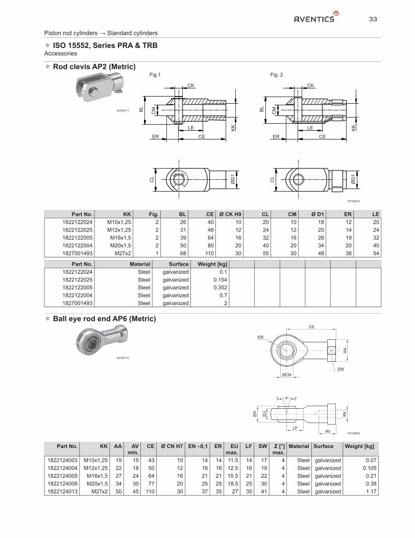
Rod clevis AP2 (Metric)
00105171
Fig.1 Fig. 2
BL
CM
CK
KK
KK LE
CEERB
L
CL
ØD
1
CL
ØD
1
CM
CK
LE
CEER
00126410
Part No. KK Fig. BL CE Ø CK H9 CL CM Ø D1 ER LE1822122024 M10x1,25 2 26 40 10 20 10 18 12 201822122025 M12x1,25 2 31 48 12 24 12 20 14 241822122005 M16x1,5 2 39 64 16 32 16 26 19 321822122004 M20x1,5 2 50 80 20 40 20 34 20 401827001493 M27x2 1 68 110 30 55 30 48 38 54
Part No. Material Surface Weight [kg]1822122024 Steel galvanized 0.11822122025 Steel galvanized 0.1541822122005 Steel galvanized 0.3521822122004 Steel galvanized 0.71827001493 Steel galvanized 2
Ball eye rod end AP6 (Metric)
00105172
LFAV
EU
EN
KK
CE
AA
ØCN
ER
SW
z z
00126602
Part No. KK AA AV min.
CE Ø CN H7 EN –0,1 ER EU max.
LF SW Z [°]max.
Material Surface Weight [kg]
1822124003 M10x1,25 19 15 43 10 14 14 11.5 14 17 4 Steel galvanized 0.071822124004 M12x1,25 22 18 50 12 16 16 12.5 16 19 4 Steel galvanized 0.1051822124005 M16x1,5 27 24 64 16 21 21 15.5 21 22 4 Steel galvanized 0.211822124006 M20x1,5 34 30 77 20 25 25 18.5 25 30 4 Steel galvanized 0.381822124013 M27x2 50 45 110 30 37 35 27 35 41 4 Steel galvanized 1.17
34
Piston rod cylinders → Standard cylinders
ISO 15552, Series PRA & TRBAccessories
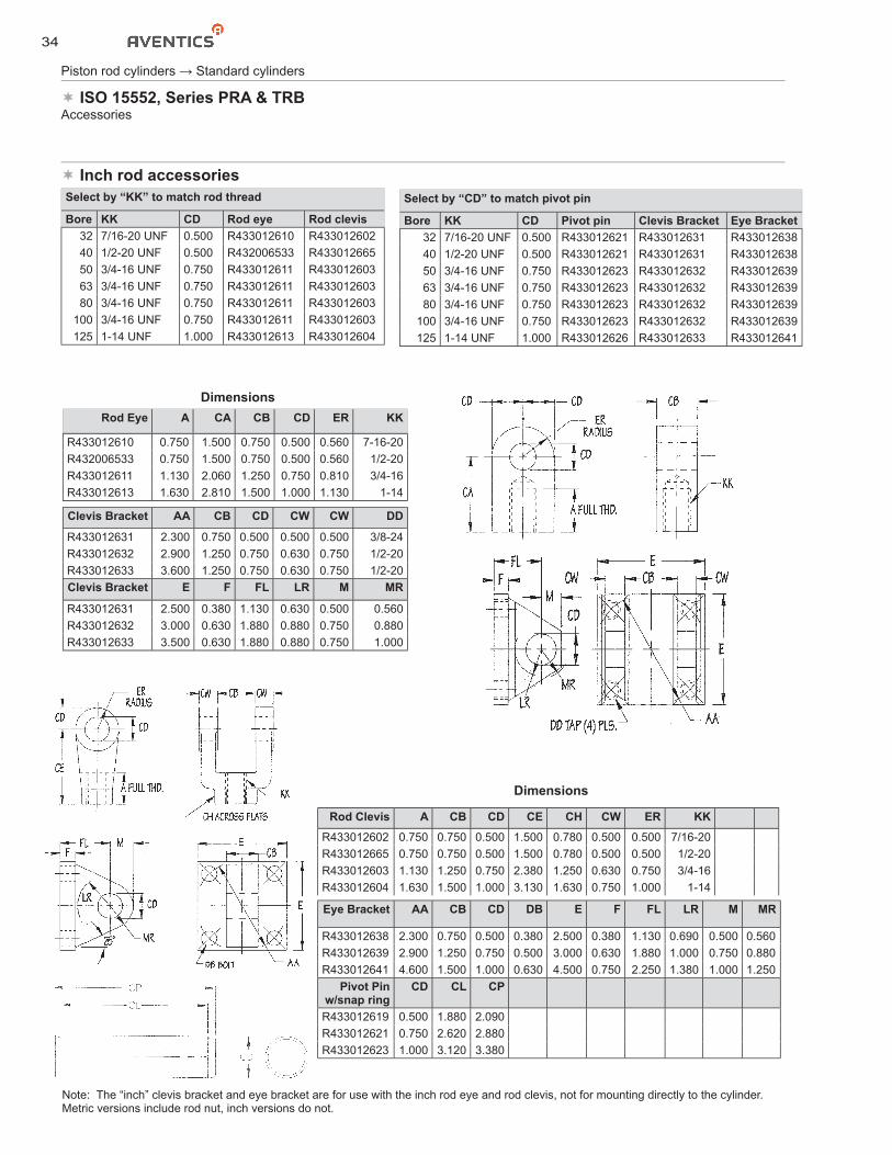
Inch rod accessoriesSelect by “KK” to match rod thread
Bore KK CD Rod eye Rod clevis32 7/16-20 UNF 0.500 R433012610 R43301260240 1/2-20 UNF 0.500 R432006533 R43301266550 3/4-16 UNF 0.750 R433012611 R43301260363 3/4-16 UNF 0.750 R433012611 R43301260380 3/4-16 UNF 0.750 R433012611 R433012603
100 3/4-16 UNF 0.750 R433012611 R433012603125 1-14 UNF 1.000 R433012613 R433012604
Select by “CD” to match pivot pin
Bore KK CD Pivot pin Clevis Bracket Eye Bracket32 7/16-20 UNF 0.500 R433012621 R433012631 R43301263840 1/2-20 UNF 0.500 R433012621 R433012631 R43301263850 3/4-16 UNF 0.750 R433012623 R433012632 R43301263963 3/4-16 UNF 0.750 R433012623 R433012632 R43301263980 3/4-16 UNF 0.750 R433012623 R433012632 R433012639
100 3/4-16 UNF 0.750 R433012623 R433012632 R433012639125 1-14 UNF 1.000 R433012626 R433012633 R433012641
Rod Eye A CA CB CD ER KK
R433012610 0.750 1.500 0.750 0.500 0.560 7-16-20R432006533 0.750 1.500 0.750 0.500 0.560 1/2-20R433012611 1.130 2.060 1.250 0.750 0.810 3/4-16R433012613 1.630 2.810 1.500 1.000 1.130 1-14
Clevis Bracket AA CB CD CW CW DD
R433012631 2.300 0.750 0.500 0.500 0.500 3/8-24R433012632 2.900 1.250 0.750 0.630 0.750 1/2-20R433012633 3.600 1.250 0.750 0.630 0.750 1/2-20Clevis Bracket E F FL LR M MR
R433012631 2.500 0.380 1.130 0.630 0.500 0.560R433012632 3.000 0.630 1.880 0.880 0.750 0.880R433012633 3.500 0.630 1.880 0.880 0.750 1.000
Note: The “inch” clevis bracket and eye bracket are for use with the inch rod eye and rod clevis, not for mounting directly to the cylinder.Metric versions include rod nut, inch versions do not.
Rod Clevis A CB CD CE CH CW ER KK
R433012602 0.750 0.750 0.500 1.500 0.780 0.500 0.500 7/16-20R433012665 0.750 0.750 0.500 1.500 0.780 0.500 0.500 1/2-20R433012603 1.130 1.250 0.750 2.380 1.250 0.630 0.750 3/4-16R433012604 1.630 1.500 1.000 3.130 1.630 0.750 1.000 1-14
Eye Bracket AA CB CD DB E F FL LR M MR
R433012638 2.300 0.750 0.500 0.380 2.500 0.380 1.130 0.690 0.500 0.560R433012639 2.900 1.250 0.750 0.500 3.000 0.630 1.880 1.000 0.750 0.880R433012641 4.600 1.500 1.000 0.630 4.500 0.750 2.250 1.380 1.000 1.250
Pivot Pin w/snap ring
CD CL CP
R433012619 0.500 1.880 2.090R433012621 0.750 2.620 2.880R433012623 1.000 3.120 3.380
Dimensions
Dimensions
35
Piston rod cylinders → Standard cylinders
ISO 15552, Series PRA & TRBAccessories
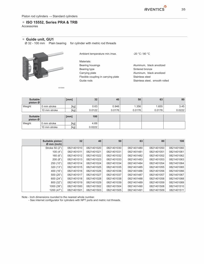
Guide unit, GU1� Ø 32 - 100 mm � Plain bearing � for cylinder with metric rod threads
00105859
Ambient temperature min./max. -20 °C / 80 °C
Materials:Bearing housings Aluminum, black anodizedBearing type Sintered bronzeCarrying plate Aluminum, black anodizedFlexible coupling in carrying plate Stainless steelGuide rods Stainless steel, smooth rolled
Suitable piston Ø
[mm] 32 40 50 63 80
Weight 0 mm stroke [kg] 0.63 0.946 1.356 1.655 3.4510 mm stroke [kg] 0.0122 0.0176 0.0176 0.0176 0.0222
Suitable piston Ø
[mm] 100
Weight 0 mm stroke [kg] 4.6910 mm stroke [kg] 0.0222
Suitable piston Ø mm (inch)
32 40 50 63 80 100
Stroke 50 (2”) 0821401010 0821401020 0821401030 0821401480 0821401050 0821401060100 (4”) 0821401011 0821401021 0821401031 0821401481 0821401051 0821401061160 (6”) 0821401012 0821401022 0821401032 0821401482 0821401052 0821401062200 (8”) 0821401013 0821401023 0821401033 0821401483 0821401053 0821401063
250 (10”) 0821401014 0821401024 0821401034 0821401484 0821401054 0821401064320 (13”) 0821401015 0821401025 0821401035 0821401485 0821401055 0821401065400 (16”) 0821401016 0821401026 0821401036 0821401486 0821401056 0821401066500 (20”) 0821401017 0821401027 0821401037 0821401487 0821401057 0821401067600 (24”) 0821401018 0821401028 0821401038 0821401488 0821401058 0821401068800 (32”) 0821401019 0821401029 0821401039 0821401489 0821401059 0821401069
1000 (39”) 0821401500 0821401502 0821401504 0821401490 0821401508 08214015101200 (47”) 0821401501 0821401503 0821401505 0821401491 0821401509 0821401511
Note - Inch dimensions rounded to the nearest whole number. - See internet configurator for cylinders with NPT ports and metric rod threads.
36
Piston rod cylinders → Standard cylinders
ISO 15552, Series PRA & TRBAccessories
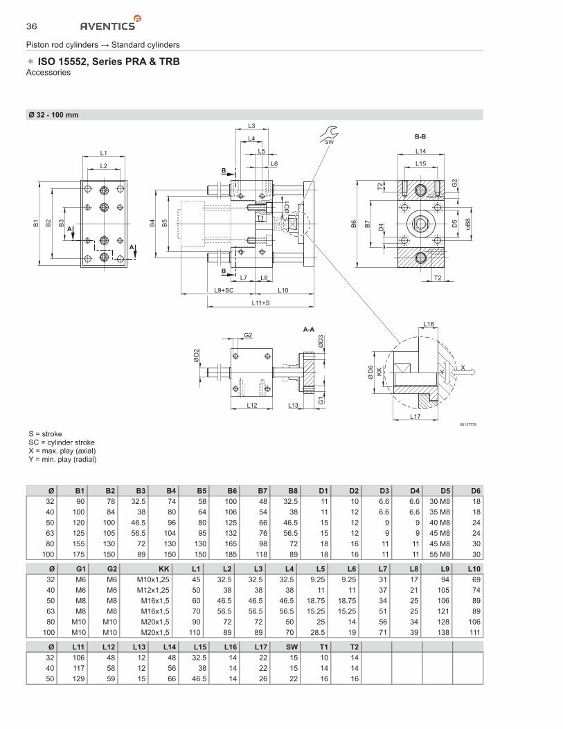
Ø 32 - 100 mm
L16
B1
B4
B6B2
B5
B3
T2
L2
L1
D3
D1
D4
G1
B7
D5
G2
B8
D6
KK
L17
L9+SC L10
L11+S
L7
L5
L4
L3
L14
L15
L8 T2
T1
L6
G2A-A
B-B
A
A
B
B
SW
YX
Y
D2
L12 L13
00127778
S = strokeSC = cylinder strokeX = max. play (axial)Y = min. play (radial)
Ø B1 B2 B3 B4 B5 B6 B7 B8 D1 D2 D3 D4 D5 D632 90 78 32.5 74 58 100 48 32.5 11 10 6.6 6.6 30 M8 1840 100 84 38 80 64 106 54 38 11 12 6.6 6.6 35 M8 1850 120 100 46.5 96 80 125 66 46.5 15 12 9 9 40 M8 2463 125 105 56.5 104 95 132 76 56.5 15 12 9 9 45 M8 2480 155 130 72 130 130 165 98 72 18 16 11 11 45 M8 30
100 175 150 89 150 150 185 118 89 18 16 11 11 55 M8 30
Ø G1 G2 KK L1 L2 L3 L4 L5 L6 L7 L8 L9 L1032 M6 M6 M10x1,25 45 32.5 32.5 32.5 9.25 9.25 31 17 94 6940 M6 M6 M12x1,25 50 38 38 38 11 11 37 21 105 7450 M8 M8 M16x1,5 60 46.5 46.5 46.5 18.75 18.75 34 25 106 8963 M8 M8 M16x1,5 70 56.5 56.5 56.5 15.25 15.25 51 25 121 8980 M10 M10 M20x1,5 90 72 72 50 25 14 56 34 128 106
100 M10 M10 M20x1,5 110 89 89 70 28.5 19 71 39 138 111
Ø L11 L12 L13 L14 L15 L16 L17 SW T1 T232 106 48 12 48 32.5 14 22 15 10 1440 117 58 12 56 38 14 22 15 14 1450 129 59 15 66 46.5 14 26 22 16 16
37
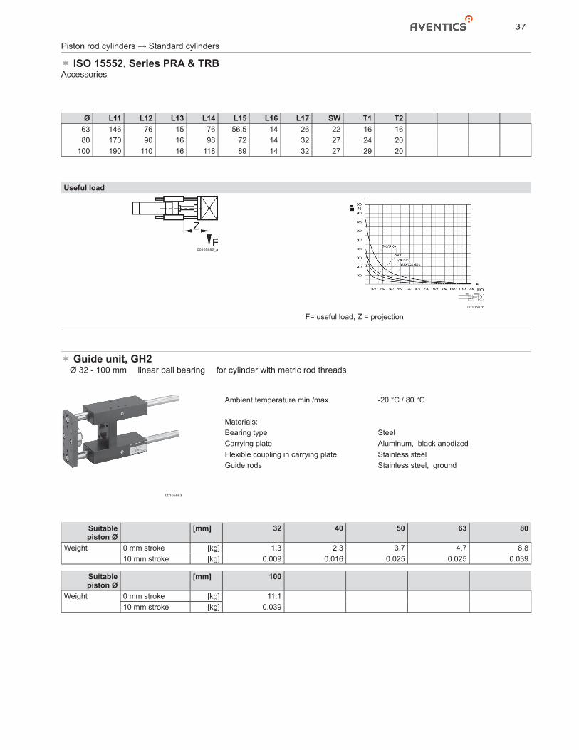
Piston rod cylinders → Standard cylinders
ISO 15552, Series PRA & TRBAccessories
Ø L11 L12 L13 L14 L15 L16 L17 SW T1 T263 146 76 15 76 56.5 14 26 22 16 1680 170 90 16 98 72 14 32 27 24 20
100 190 110 16 118 89 14 32 27 29 20
Useful load
00105882_a
00105876
F= useful load, Z = projection
Guide unit, GH2� Ø 32 - 100 mm � linear ball bearing � for cylinder with metric rod threads
00105863
Ambient temperature min./max. -20 °C / 80 °C
Materials:Bearing type SteelCarrying plate Aluminum, black anodizedFlexible coupling in carrying plate Stainless steelGuide rods Stainless steel, ground
Suitablepiston Ø
[mm] 32 40 50 63 80
Weight 0 mm stroke [kg] 1.3 2.3 3.7 4.7 8.810 mm stroke [kg] 0.009 0.016 0.025 0.025 0.039
Suitablepiston Ø
[mm] 100
Weight 0 mm stroke [kg] 11.110 mm stroke [kg] 0.039
38
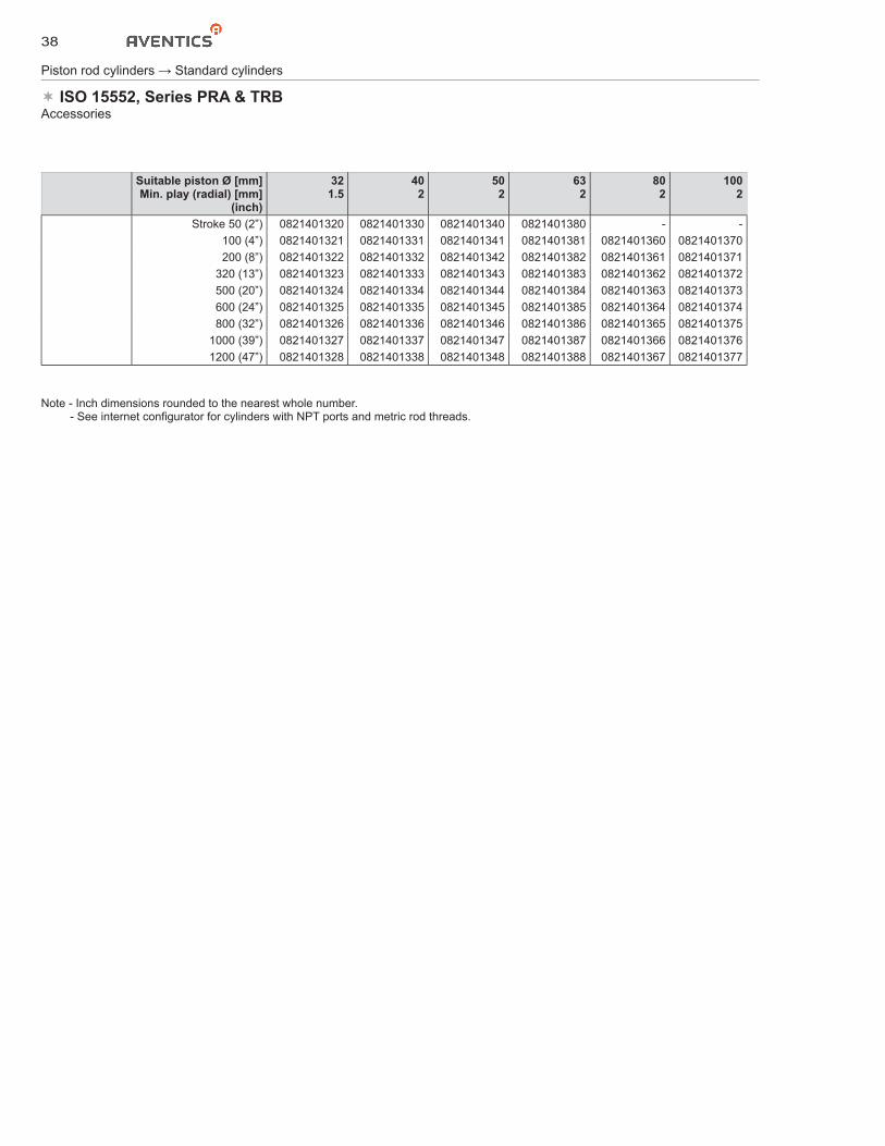
Piston rod cylinders → Standard cylinders
ISO 15552, Series PRA & TRBAccessories
Suitable piston Ø [mm]Min. play (radial) [mm]
(inch)
321.5
402
502
632
802
1002
Stroke 50 (2”) 0821401320 0821401330 0821401340 0821401380 - -100 (4”) 0821401321 0821401331 0821401341 0821401381 0821401360 0821401370200 (8”) 0821401322 0821401332 0821401342 0821401382 0821401361 0821401371
320 (13”) 0821401323 0821401333 0821401343 0821401383 0821401362 0821401372500 (20”) 0821401324 0821401334 0821401344 0821401384 0821401363 0821401373600 (24”) 0821401325 0821401335 0821401345 0821401385 0821401364 0821401374800 (32”) 0821401326 0821401336 0821401346 0821401386 0821401365 0821401375
1000 (39”) 0821401327 0821401337 0821401347 0821401387 0821401366 08214013761200 (47”) 0821401328 0821401338 0821401348 0821401388 0821401367 0821401377
Note - Inch dimensions rounded to the nearest whole number. - See internet configurator for cylinders with NPT ports and metric rod threads.
39
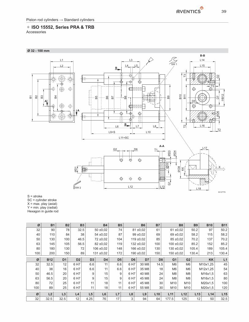
Piston rod cylinders → Standard cylinders
ISO 15552, Series PRA & TRBAccessories
Ø 32 - 100 mm
L17
B1
B2
B3
B4
B5
G1
D2
D1
D8
KK
D3
D4
B6
B7
B8
D6
D7
B9
B12
B11
T2
T2
G2T3
T3
B10
L2 L4 L15
L16
L18
G2 D6 T1
L5
L1 L3 L14
L12
L11+SC
L9+S
L6
L10
L8L7
L13
A
A
A-A
B-B
B
B
SW 1
SW 2
D5
YX
Y
00127779
S = strokeSC = cylinder strokeX = max. play (axial)Y = min. play (radial)Hexagon in guide rod
Ø B1 B2 B3 B4 B5 B6 B7 B8 B9 B10 B1132 90 78 32.5 50 ±0,02 74 81 ±0,02 61 61 ±0,02 50.2 97 50.240 110 84 38 54 ±0,02 87 99 ±0,02 69 69 ±0,02 58.2 115 58.250 130 100 46.5 72 ±0,02 104 119 ±0,02 85 85 ±0,02 70.2 137 70.263 145 105 56.5 82 ±0,02 119 132 ±0,02 100 100 ±0,02 85.2 152 85.280 180 130 72 106 ±0,02 148 166 ±0,02 130 130 ±0,02 105.4 189 105.4
100 200 150 89 131 ±0,02 172 190 ±0,02 150 150 ±0,02 130.4 213 130.4
Ø B12 D1 D2 D3 D4 D5 D6 D7 D8 G1 G2 KK L132 32.5 12 6 H7 6.6 11 6.6 6 H7 30 M8 14.5 M6 M6 M10x1,25 4540 38 16 6 H7 6.6 11 6.6 6 H7 35 M8 18 M6 M6 M12x1,25 5450 46.5 20 6 H7 9 15 9 6 H7 40 M8 24 M8 M8 M16x1,5 6363 56.5 20 6 H7 9 15 9 6 H7 45 M8 24 M8 M8 M16x1,5 8080 72 25 6 H7 11 18 11 6 H7 45 M8 30 M10 M10 M20x1,5 100
100 89 25 6 H7 11 18 11 6 H7 55 M8 30 M10 M10 M20x1,5 120
Ø L2 L3 L4 L5 L6 L7 L8 L9 L10 L11 L12 L13 L14 L1532 32.5 32.5 12 4.25 76 17 3 94 64 177.5 125 12 50 32.5
40
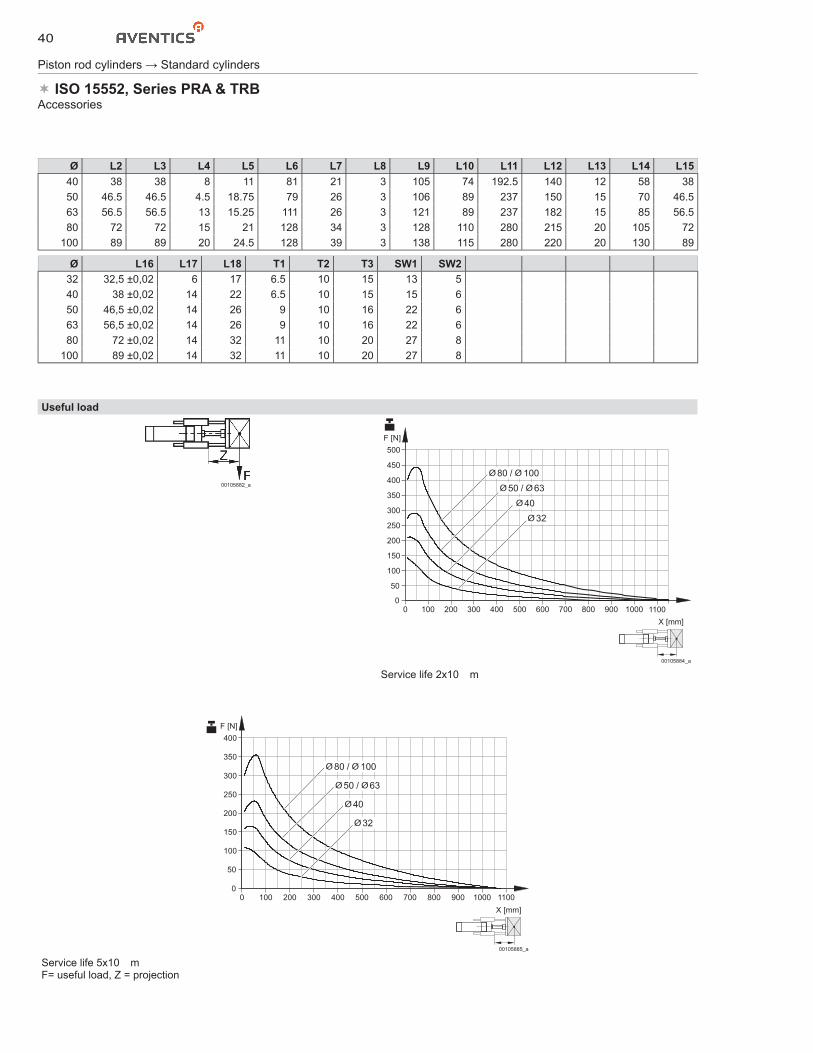
Piston rod cylinders → Standard cylinders
ISO 15552, Series PRA & TRBAccessories
Ø L2 L3 L4 L5 L6 L7 L8 L9 L10 L11 L12 L13 L14 L1540 38 38 8 11 81 21 3 105 74 192.5 140 12 58 3850 46.5 46.5 4.5 18.75 79 26 3 106 89 237 150 15 70 46.563 56.5 56.5 13 15.25 111 26 3 121 89 237 182 15 85 56.580 72 72 15 21 128 34 3 128 110 280 215 20 105 72
100 89 89 20 24.5 128 39 3 138 115 280 220 20 130 89
Ø L16 L17 L18 T1 T2 T3 SW1 SW232 32,5 ±0,02 6 17 6.5 10 15 13 540 38 ±0,02 14 22 6.5 10 15 15 650 46,5 ±0,02 14 26 9 10 16 22 663 56,5 ±0,02 14 26 9 10 16 22 680 72 ±0,02 14 32 11 10 20 27 8
100 89 ±0,02 14 32 11 10 20 27 8
Useful load
00105882_a
X [mm]
F [N]
00
300
250
200
150
100
50
350
500
400
450
100 200 300 400 500 600 700 800 900 1000 1100
32
40
50
80
63
100
/
/
00105884_a
Service life 2x10� m
X [mm]
F [N]
00
300
250
200
150
100
50
350
400
100 200 300 400 500 600 700 800 900 1000 1100
32
40
50
80
63
100
/
/
00105885_a
Service life 5x10� mF= useful load, Z = projection
41
Piston rod cylinders → Standard cylinders
ISO 15552, Series PRA & TRBAccessories
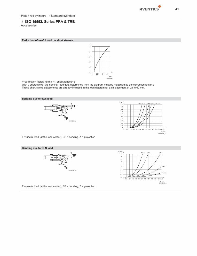
Reduction of useful load on short strokes
00105886_a
k=correction factor: normal=1; shock loaded=2With a short stroke, the nominal load data determined from the diagram must be multiplied by the correction factor k.These short-stroke adjustments are already included in the load diagram for a displacement of up to 60 mm.
Bending due to own load
00105887_a
00105888_a
F = useful load (at the load center), SF = bending, Z = projection
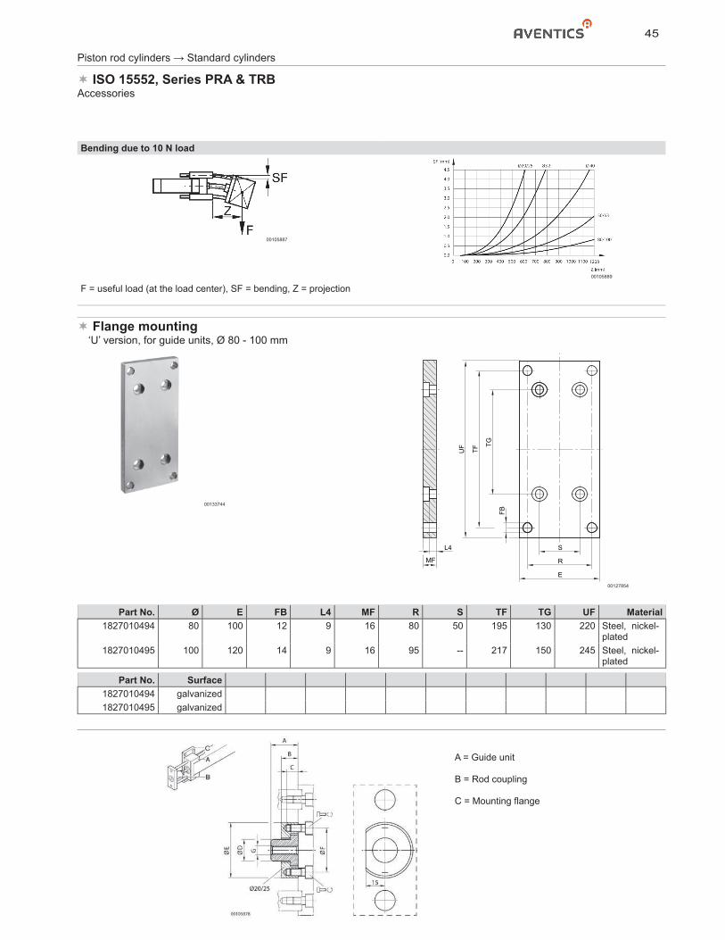
Bending due to 10 N load
00105887_a
00105889_a
F = useful load (at the load center), SF = bending, Z = projection
42
Piston rod cylinders → Standard cylinders
ISO 15552, Series PRA & TRBAccessories
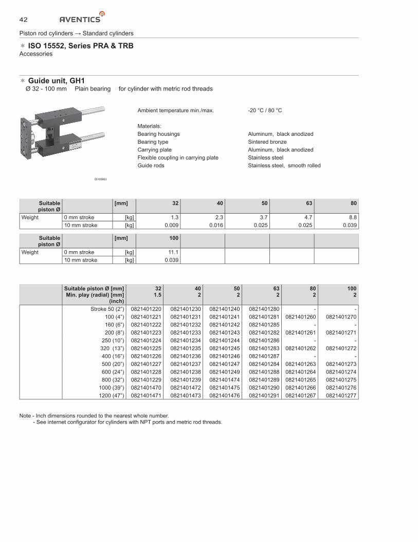
Guide unit, GH1� Ø 32 - 100 mm � Plain bearing � for cylinder with metric rod threads
00105863
Ambient temperature min./max. -20 °C / 80 °C
Materials:Bearing housings Aluminum, black anodizedBearing type Sintered bronzeCarrying plate Aluminum, black anodizedFlexible coupling in carrying plate Stainless steelGuide rods Stainless steel, smooth rolled
Suitablepiston Ø
[mm] 32 40 50 63 80
Weight 0 mm stroke [kg] 1.3 2.3 3.7 4.7 8.810 mm stroke [kg] 0.009 0.016 0.025 0.025 0.039
Suitablepiston Ø
[mm] 100
Weight 0 mm stroke [kg] 11.110 mm stroke [kg] 0.039
Suitable piston Ø [mm]Min. play (radial) [mm]
(inch)
321.5
402
502
632
802
1002
Stroke 50 (2”) 0821401220 0821401230 0821401240 0821401280 - -100 (4”) 0821401221 0821401231 0821401241 0821401281 0821401260 0821401270160 (6”) 0821401222 0821401232 0821401242 0821401285 - -200 (8”) 0821401223 0821401233 0821401243 0821401282 0821401261 0821401271
250 (10”) 0821401224 0821401234 0821401244 0821401286 - -320 (13”) 0821401225 0821401235 0821401245 0821401283 0821401262 0821401272400 (16”) 0821401226 0821401236 0821401246 0821401287 - -500 (20”) 0821401227 0821401237 0821401247 0821401284 0821401263 0821401273600 (24”) 0821401228 0821401238 0821401249 0821401288 0821401264 0821401274800 (32”) 0821401229 0821401239 0821401474 0821401289 0821401265 0821401275
1000 (39”) 0821401470 0821401472 0821401475 0821401290 0821401266 08214012761200 (47”) 0821401471 0821401473 0821401476 0821401291 0821401267 0821401277
Note - Inch dimensions rounded to the nearest whole number. - See internet configurator for cylinders with NPT ports and metric rod threads.
43
Piston rod cylinders → Standard cylinders
ISO 15552, Series PRA & TRBAccessories
Ø 32 - 100 mm
L17
B1
B2
B3
B4
B5
G1
D2
D1
D8
KK
D3
D4
B6
B7
B8
D6
D7
B9
B12
B11
T2
T2
G2T3
T3
B10
L2 L4 L15
L16
L18
G2 D6 T1
L5
L1 L3 L14
L12
L11+SC
L9+S
L6
L10
L8L7
L13
A
A
A-A
B-B
B
B
SW 1
D5
YX
Y
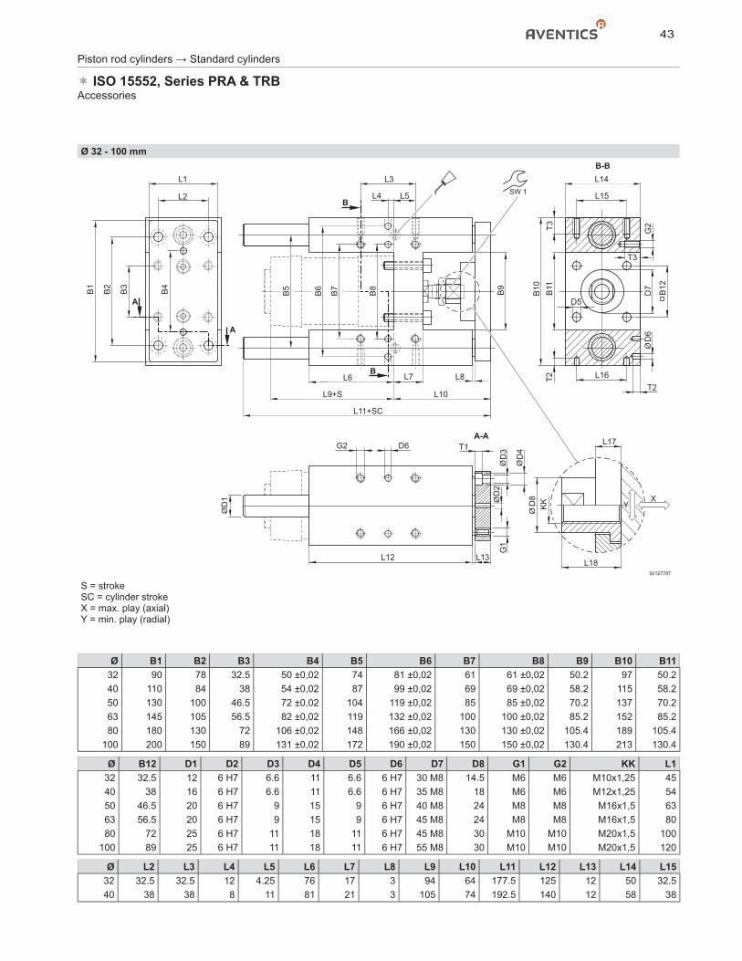
00127787
S = strokeSC = cylinder strokeX = max. play (axial)Y = min. play (radial)
Ø B1 B2 B3 B4 B5 B6 B7 B8 B9 B10 B1132 90 78 32.5 50 ±0,02 74 81 ±0,02 61 61 ±0,02 50.2 97 50.240 110 84 38 54 ±0,02 87 99 ±0,02 69 69 ±0,02 58.2 115 58.250 130 100 46.5 72 ±0,02 104 119 ±0,02 85 85 ±0,02 70.2 137 70.263 145 105 56.5 82 ±0,02 119 132 ±0,02 100 100 ±0,02 85.2 152 85.280 180 130 72 106 ±0,02 148 166 ±0,02 130 130 ±0,02 105.4 189 105.4
100 200 150 89 131 ±0,02 172 190 ±0,02 150 150 ±0,02 130.4 213 130.4
Ø B12 D1 D2 D3 D4 D5 D6 D7 D8 G1 G2 KK L132 32.5 12 6 H7 6.6 11 6.6 6 H7 30 M8 14.5 M6 M6 M10x1,25 4540 38 16 6 H7 6.6 11 6.6 6 H7 35 M8 18 M6 M6 M12x1,25 5450 46.5 20 6 H7 9 15 9 6 H7 40 M8 24 M8 M8 M16x1,5 6363 56.5 20 6 H7 9 15 9 6 H7 45 M8 24 M8 M8 M16x1,5 8080 72 25 6 H7 11 18 11 6 H7 45 M8 30 M10 M10 M20x1,5 100
100 89 25 6 H7 11 18 11 6 H7 55 M8 30 M10 M10 M20x1,5 120
Ø L2 L3 L4 L5 L6 L7 L8 L9 L10 L11 L12 L13 L14 L1532 32.5 32.5 12 4.25 76 17 3 94 64 177.5 125 12 50 32.540 38 38 8 11 81 21 3 105 74 192.5 140 12 58 38
44
Piston rod cylinders → Standard cylinders
ISO 15552, Series PRA & TRBAccessories
Ø L2 L3 L4 L5 L6 L7 L8 L9 L10 L11 L12 L13 L14 L1550 46.5 46.5 4.5 18.75 79 26 3 106 89 205 150 15 70 46.563 56.5 56.5 13 15.25 111 26 3 121 89 237 182 15 85 56.580 72 72 15 21 128 34 3 128 110 280 215 20 105 72
100 89 89 20 24.5 128 39 3 138 115 280 220 20 130 89
Ø L16 L17 L18 T1 T2 T3 SW132 32,5 ±0,02 6 17 6.5 10 15 1340 38 ±0,02 14 22 6.5 10 15 1550 46,5 ±0,02 14 26 9 10 16 2263 56,5 ±0,02 14 26 9 10 16 2280 72 ±0,02 14 32 11 10 20 27
100 89 ±0,02 14 32 11 10 20 27
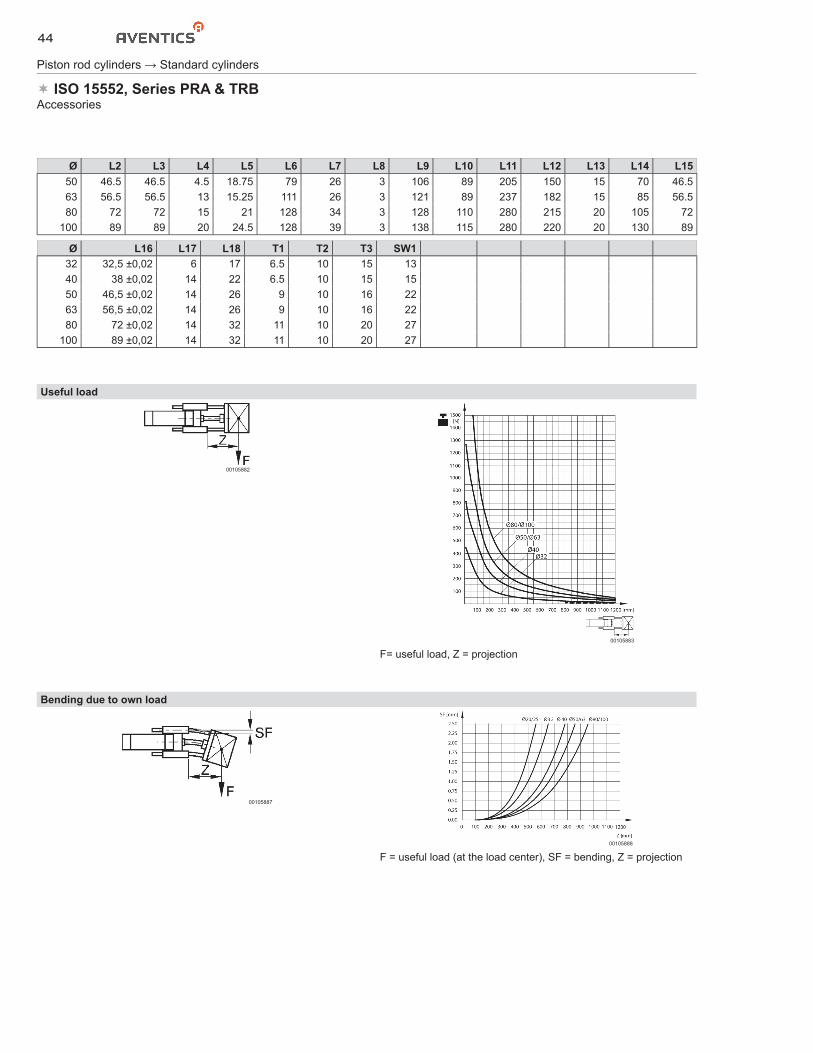
Useful load
00105882
00105883
F= useful load, Z = projection
Bending due to own load
00105887
00105888
F = useful load (at the load center), SF = bending, Z = projection
45
Piston rod cylinders → Standard cylinders
ISO 15552, Series PRA & TRBAccessories
Bending due to 10 N load
00105887
00105889
F = useful load (at the load center), SF = bending, Z = projection
Flange mounting� ‘U’ version, for guide units, Ø 80 - 100 mm
00133744
TG
FB
TF
S
E
R
L4
MF
UF
00127854
Part No. Ø E FB L4 MF R S TF TG UF Material1827010494 80 100 12 9 16 80 50 195 130 220 Steel, nickel-
plated1827010495 100 120 14 9 16 95 -- 217 150 245 Steel, nickel-
plated
Part No. Surface1827010494 galvanized1827010495 galvanized
A = Guide unit
B = Rod coupling
C = Mounting flange

46
Piston rod cylinders → Standard cylinders
ISO 15552, Series PRA & TRBAccessories
Flange mounting� for guide units, ‘H’ version, Ø 12 - 100 mm
00106403
00106476
Part No. Ø E Ø FB L4 MF R TF TG UF Material Surface1821038163 12/16 50 5.5 4.5 10 32.5 50 23 64 Steel, galvanized galvanized1821038078 20/25 50 6.6 4.5 10 32.5 50 23 64 Steel, galvanized galvanized1821038079 32 50 6.6 4.5 10 32.5 116 61 130 Steel, galvanized galvanized1821038080 40 55 9 4.5 10 38 140 69 160 Steel, galvanized galvanized1821038081 50 70 9 6 12 46.5 160 85 180 Steel, galvanized galvanized1821038082 63 80 9 6 12 56.5 175 100 195 Steel, galvanized galvanized1821038083 80 100 12 9 16 72 218 130 242 Steel, galvanized galvanized1821038084 100 120 14 9 16 89 245 150 272 Steel, galvanized galvanized
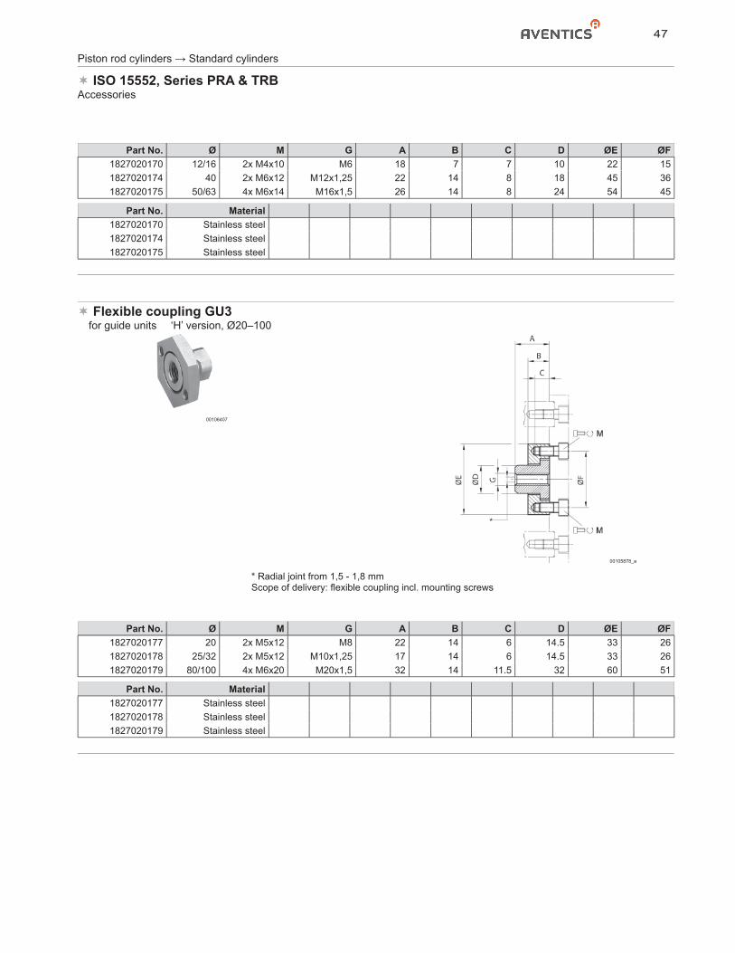
Flexible coupling GU3� for guide units � version ‘U’ and ‘H’, Ø12–63
00105864
00132063
* Radial joint from 2 - 2,5 mmScope of delivery: flexible coupling incl. mounting screws
A = Guide unit
B = Rod coupling
C = Mounting flange
47
Piston rod cylinders → Standard cylinders
ISO 15552, Series PRA & TRBAccessories
Part No. Ø M G A B C D ØE ØF1827020170 12/16 2x M4x10 M6 18 7 7 10 22 151827020174 40 2x M6x12 M12x1,25 22 14 8 18 45 361827020175 50/63 4x M6x14 M16x1,5 26 14 8 24 54 45
Part No. Material1827020170 Stainless steel1827020174 Stainless steel1827020175 Stainless steel
Flexible coupling GU3� for guide units � ‘H’ version, Ø20–100
00106407
00105878_a
* Radial joint from 1,5 - 1,8 mmScope of delivery: flexible coupling incl. mounting screws
Part No. Ø M G A B C D ØE ØF1827020177 20 2x M5x12 M8 22 14 6 14.5 33 261827020178 25/32 2x M5x12 M10x1,25 17 14 6 14.5 33 261827020179 80/100 4x M6x20 M20x1,5 32 14 11.5 32 60 51
Part No. Material1827020177 Stainless steel1827020178 Stainless steel1827020179 Stainless steel
48
Piston rod cylinders → Standard cylinders
ISO 15552, Series PRA & TRBAccessories
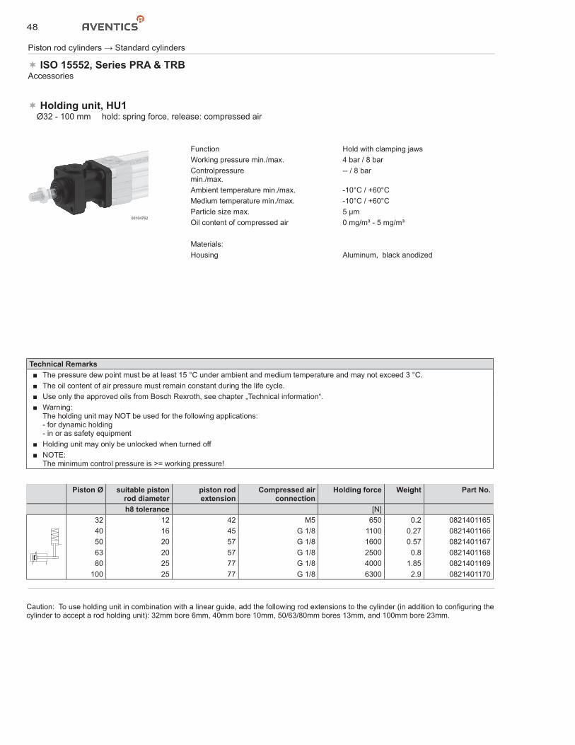
Holding unit, HU1� Ø32 - 100 mm � hold: spring force, release: compressed air
00104762
Function Hold with clamping jawsWorking pressure min./max. 4 bar / 8 barControlpressuremin./max.
-- / 8 bar
Ambient temperature min./max. -10°C / +60°CMedium temperature min./max. -10°C / +60°CParticle size max. 5 μmOil content of compressed air 0 mg/m³ - 5 mg/m³
Materials:Housing Aluminum, black anodized
Technical Remarks■ The pressure dew point must be at least 15 °C under ambient and medium temperature and may not exceed 3 °C.■ The oil content of air pressure must remain constant during the life cycle.■ Use only the approved oils from Bosch Rexroth, see chapter „Technical information“.■ Warning:
The holding unit may NOT be used for the following applications:- for dynamic holding- in or as safety equipment
■ Holding unit may only be unlocked when turned off■ NOTE:
The minimum control pressure is >= working pressure!
Piston Ø suitable piston rod diameter
piston rodextension
Compressed air connection
Holding force Weight Part No.
h8 tolerance [N]32 12 42 M5 650 0.2 082140116540 16 45 G 1/8 1100 0.27 082140116650 20 57 G 1/8 1600 0.57 082140116763 20 57 G 1/8 2500 0.8 082140116880 25 77 G 1/8 4000 1.85 0821401169
100 25 77 G 1/8 6300 2.9 0821401170
Caution: To use holding unit in combination with a linear guide, add the following rod extensions to the cylinder (in addition to configuring the cylinder to accept a rod holding unit): 32mm bore 6mm, 40mm bore 10mm, 50/63/80mm bores 13mm, and 100mm bore 23mm.
49
Piston rod cylinders → Standard cylinders
ISO 15552, Series PRA & TRBAccessories
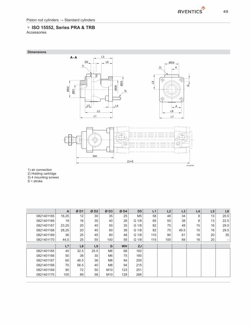
Dimensions
D5 L6
D3
D6
D2
ØD
1
L4L5
L3
D4
G
L7
L8
L9
A
A
L2
L1
WH
ZJ+S
3)
2)1)
A - A
00129789
1) air connection2) Holding cartridge3) 4 mounting screwsS = stroke
A Ø D1 Ø D2 Ø D3 Ø D4 D5 L1 L2 L3 L4 L5 L60821401165 16,25 12 30 35 25 M5 58 48 34 8 13 20.50821401166 19 16 35 40 28 G 1/8 65 55 38 8 13 22.50821401167 23,25 20 40 50 35 G 1/8 82 70 48 15 16 29.50821401168 28,25 20 45 60 38 G 1/8 82 70 49.5 15 16 29.50821401169 36 25 45 80 48 G 1/8 110 90 61 18 20 350821401170 44,5 25 55 100 58 G 1/8 115 100 69 18 20 –
L7 L8 L9 G WH ZJ0821401165 45 32.5 25.5 M6 68 1620821401166 50 38 30 M6 75 1800821401167 60 46.5 36 M8 94 2000821401168 70 56.5 40 M8 94 2150821401169 90 72 50 M10 123 2510821401170 105 89 58 M10 128 266
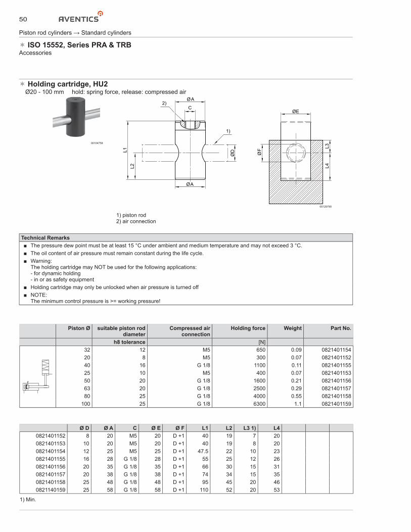
50
Piston rod cylinders → Standard cylinders
ISO 15552, Series PRA & TRBAccessories
Holding cartridge, HU2� Ø20 - 100 mm � hold: spring force, release: compressed air
00104758
A
CE
L3
F
L4
L1
L2
D
1)
2)
A
00129790
1) piston rod2) air connection
Technical Remarks■ The pressure dew point must be at least 15 °C under ambient and medium temperature and may not exceed 3 °C.■ The oil content of air pressure must remain constant during the life cycle.■ Warning:
The holding cartridge may NOT be used for the following applications:- for dynamic holding- in or as safety equipment
■ Holding cartridge may only be unlocked when air pressure is turned off■ NOTE:
The minimum control pressure is >= working pressure!
Piston Ø suitable piston rod diameter
Compressed airconnection
Holding force Weight Part No.
h8 tolerance [N]32 12 M5 650 0.09 082140115420 8 M5 300 0.07 082140115240 16 G 1/8 1100 0.11 082140115525 10 M5 400 0.07 082140115350 20 G 1/8 1600 0.21 082140115663 20 G 1/8 2500 0.29 082140115780 25 G 1/8 4000 0.55 0821401158
100 25 G 1/8 6300 1.1 0821401159
Ø D Ø A C Ø E Ø F L1 L2 L3 1) L40821401152 8 20 M5 20 D +1 40 19 7 200821401153 10 20 M5 20 D +1 40 19 8 200821401154 12 25 M5 25 D +1 47.5 22 10 230821401155 16 28 G 1/8 28 D +1 55 25 12 260821401156 20 35 G 1/8 35 D +1 66 30 15 310821401157 20 38 G 1/8 38 D +1 74 34 15 350821401158 25 48 G 1/8 48 D +1 95 45 20 460821140159 25 58 G 1/8 58 D +1 110 52 20 53
1) Min.
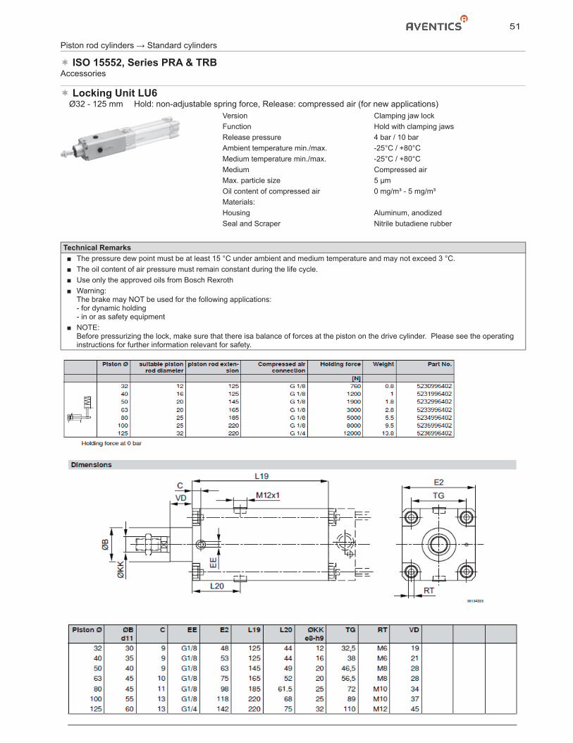
51
Locking Unit LU6� Ø32 - 125 mm � Hold: non-adjustable spring force, Release: compressed air (for new applications)
Version Clamping jaw lockFunction Hold with clamping jawsRelease pressure 4 bar / 10 barAmbient temperature min./max. -25°C / +80°CMedium temperature min./max. -25°C / +80°CMedium Compressed airMax. particle size 5 μmOil content of compressed air 0 mg/m³ - 5 mg/m³Materials:Housing Aluminum, anodizedSeal and Scraper Nitrile butadiene rubber
Piston rod cylinders → Standard cylinders
ISO 15552, Series PRA & TRBAccessories
Technical Remarks■ The pressure dew point must be at least 15 °C under ambient and medium temperature and may not exceed 3 °C.■ The oil content of air pressure must remain constant during the life cycle.■ Use only the approved oils from Bosch Rexroth■ Warning:
The brake may NOT be used for the following applications:- for dynamic holding- in or as safety equipment
■ NOTE:Before pressurizing the lock, make sure that there isa balance of forces at the piston on the drive cylinder. Please see the operating instructions for further information relevant for safety.
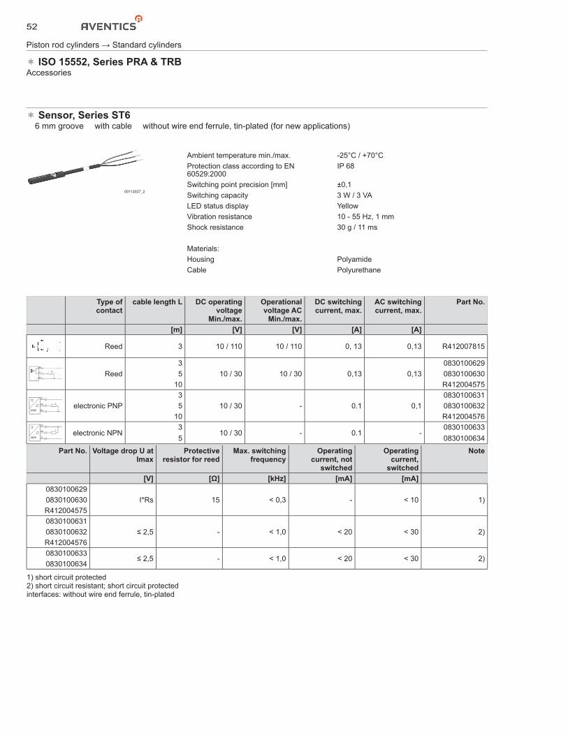
52
Piston rod cylinders → Standard cylinders
ISO 15552, Series PRA & TRBAccessories
Sensor, Series ST6� 6 mm groove � with cable � without wire end ferrule, tin-plated (for new applications)
00112027_2
Ambient temperature min./max. -25°C / +70°CProtection class according to EN 60529:2000
IP 68
Switching point precision [mm] ±0,1Switching capacity 3 W / 3 VALED status display YellowVibration resistance 10 - 55 Hz, 1 mmShock resistance 30 g / 11 ms
Materials:Housing PolyamideCable Polyurethane
Type ofcontact
cable length L DC operating voltage
Min./max.
Operational voltage AC
Min./max.
DC switching current, max.
AC switching current, max.
Part No.
[m] [V] [V] [A] [A]
Reed 3 10 / 110 10 / 110 0, 13 0,13 R412007815
BN
BK
BU
RL
+ / – / ~
– / + / ~
Reed3
10 / 30 10 / 30 0,13 0,130830100629
5 083010063010 R412004575
BN
BK
BU
RL
+
–PNPelectronic PNP
310 / 30 - 0.1 0,1
08301006315 0830100632
10 R412004576
BN
BK
BU
RL
+
–NPNelectronic NPN
310 / 30 - 0.1 -
08301006335 0830100634
Part No. Voltage drop U at Imax
Protectiveresistor for reed
Max. switching frequency
Operating current, not
switched
Operatingcurrent,
switched
Note
[V] [Ω] [kHz] [mA] [mA]0830100629
I*Rs 15 < 0,3 - < 10 1)0830100630R4120045750830100631
≤ 2,5 - < 1,0 < 20 < 30 2)0830100632R4120045760830100633
≤ 2,5 - < 1,0 < 20 < 30 2)0830100634
1) short circuit protected2) short circuit resistant; short circuit protectedinterfaces: without wire end ferrule, tin-plated
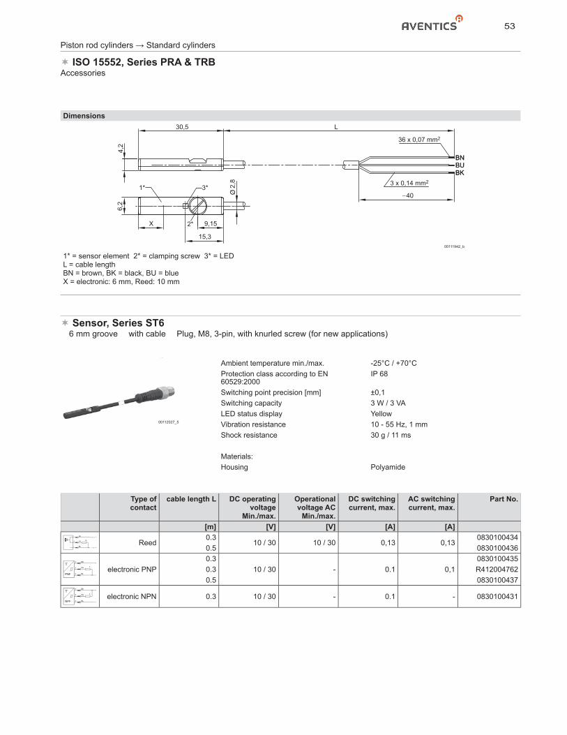
53
Piston rod cylinders → Standard cylinders
ISO 15552, Series PRA & TRBAccessories
Dimensions
BNBUBK
L30,54,
2
2,8
6,2
BNBUBK
40
3 x 0,14 mm2
36 x 0,07 mm2
9,15X
15,3
2*
3*1*
00111942_b
1* = sensor element 2* = clamping screw 3* = LEDL = cable lengthBN = brown, BK = black, BU = blueX = electronic: 6 mm, Reed: 10 mm
Sensor, Series ST6� 6 mm groove � with cable � Plug, M8, 3-pin, with knurled screw (for new applications)
00112027_5
Ambient temperature min./max. -25°C / +70°CProtection class according to EN 60529:2000
IP 68
Switching point precision [mm] ±0,1Switching capacity 3 W / 3 VALED status display YellowVibration resistance 10 - 55 Hz, 1 mmShock resistance 30 g / 11 ms
Materials:Housing Polyamide
Type ofcontact
cable length L DC operating voltage
Min./max.
Operational voltage AC
Min./max.
DC switching current, max.
AC switching current, max.
Part No.
[m] [V] [V] [A] [A]
BN
BK
BU
1
4
3
RL
+ / – / ~
– / + / ~
Reed0.3
10 / 30 10 / 30 0,13 0,130830100434
0.5 0830100436
BN
BK
BU
1
4
3
RL
+
–PNPelectronic PNP
0.310 / 30 - 0.1 0,1
08301004350.3 R4120047620.5 0830100437
BN
BK
BU
1
4
3
RL
+
–NPNelectronic NPN 0.3 10 / 30 - 0.1 - 0830100431
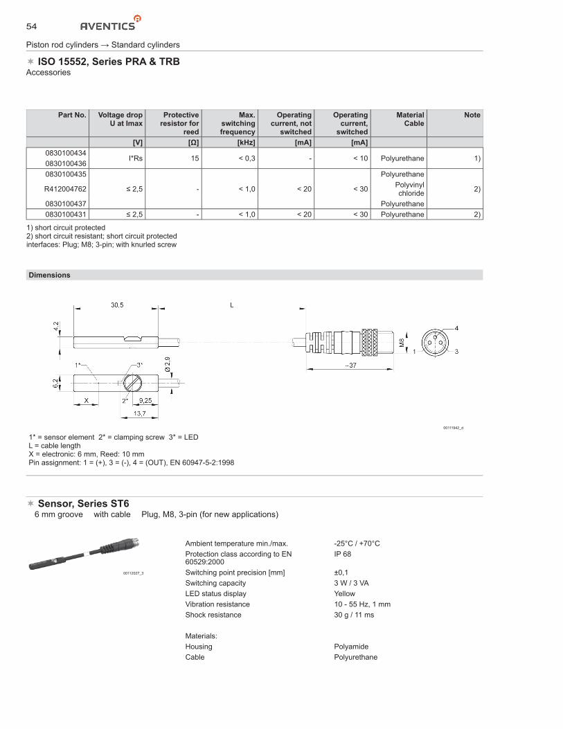
54
Piston rod cylinders → Standard cylinders
ISO 15552, Series PRA & TRBAccessories
Part No. Voltage drop U at Imax
Protective resistor for
reed
Max.switching frequency
Operating current, not
switched
Operatingcurrent,
switched
MaterialCable
Note
[V] [Ω] [kHz] [mA] [mA]0830100434
I*Rs 15 < 0,3 - < 10 Polyurethane 1)08301004360830100435
≤ 2,5 - < 1,0 < 20 < 30
Polyurethane
2)R412004762 Polyvinyl chloride
0830100437 Polyurethane0830100431 ≤ 2,5 - < 1,0 < 20 < 30 Polyurethane 2)
1) short circuit protected2) short circuit resistant; short circuit protectedinterfaces: Plug; M8; 3-pin; with knurled screw
Dimensions
00111942_d
1* = sensor element 2* = clamping screw 3* = LEDL = cable lengthX = electronic: 6 mm, Reed: 10 mmPin assignment: 1 = (+), 3 = (-), 4 = (OUT), EN 60947-5-2:1998
Sensor, Series ST6� 6 mm groove � with cable � Plug, M8, 3-pin (for new applications)
00112027_3
Ambient temperature min./max. -25°C / +70°CProtection class according to EN 60529:2000
IP 68
Switching point precision [mm] ±0,1Switching capacity 3 W / 3 VALED status display YellowVibration resistance 10 - 55 Hz, 1 mmShock resistance 30 g / 11 ms
Materials:Housing PolyamideCable Polyurethane
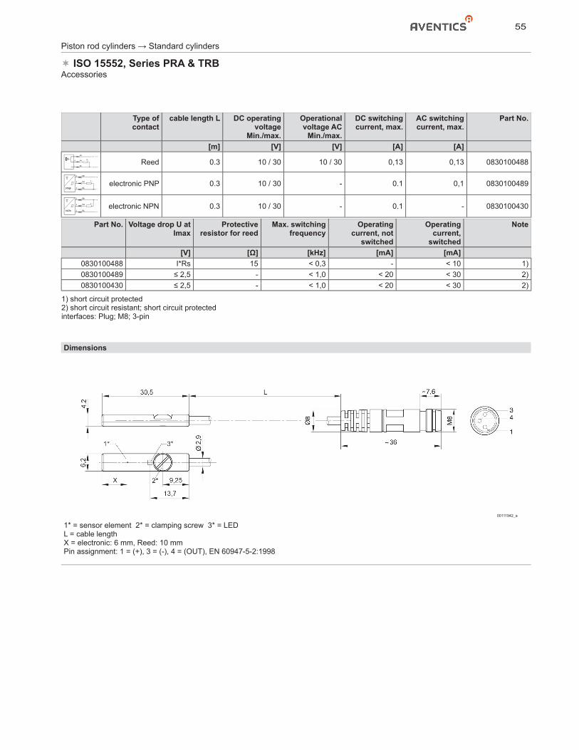
55
Piston rod cylinders → Standard cylinders
ISO 15552, Series PRA & TRBAccessories
Type ofcontact
cable length L DC operating voltage
Min./max.
Operational voltage AC
Min./max.
DC switching current, max.
AC switching current, max.
Part No.
[m] [V] [V] [A] [A]
BN
BK
BU
1
4
3
RL
+ / – / ~
– / + / ~
Reed 0.3 10 / 30 10 / 30 0,13 0,13 0830100488
BN
BK
BU
1
4
3
RL
+
–PNPelectronic PNP 0.3 10 / 30 - 0.1 0,1 0830100489
BN
BK
BU
1
4
3
RL
+
–NPNelectronic NPN 0.3 10 / 30 - 0.1 - 0830100430
Part No. Voltage drop U at Imax
Protectiveresistor for reed
Max. switching frequency
Operating current, not
switched
Operatingcurrent,
switched
Note
[V] [Ω] [kHz] [mA] [mA]0830100488 I*Rs 15 < 0,3 - < 10 1)0830100489 ≤ 2,5 - < 1,0 < 20 < 30 2)0830100430 ≤ 2,5 - < 1,0 < 20 < 30 2)
1) short circuit protected2) short circuit resistant; short circuit protectedinterfaces: Plug; M8; 3-pin
Dimensions
00111942_a
1* = sensor element 2* = clamping screw 3* = LEDL = cable lengthX = electronic: 6 mm, Reed: 10 mmPin assignment: 1 = (+), 3 = (-), 4 = (OUT), EN 60947-5-2:1998
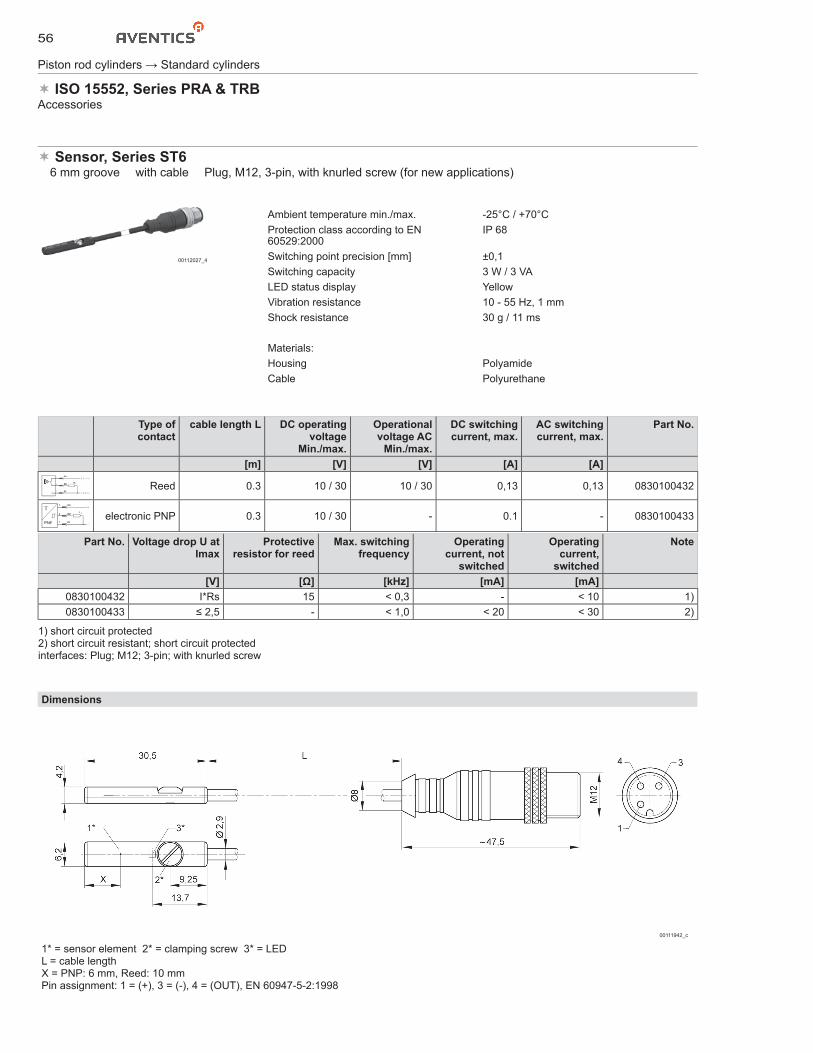
56
Piston rod cylinders → Standard cylinders
ISO 15552, Series PRA & TRBAccessories
Sensor, Series ST6� 6 mm groove � with cable � Plug, M12, 3-pin, with knurled screw (for new applications)
00112027_4
Ambient temperature min./max. -25°C / +70°CProtection class according to EN 60529:2000
IP 68
Switching point precision [mm] ±0,1Switching capacity 3 W / 3 VALED status display YellowVibration resistance 10 - 55 Hz, 1 mmShock resistance 30 g / 11 ms
Materials:Housing PolyamideCable Polyurethane
Type ofcontact
cable length L DC operating voltage
Min./max.
Operational voltage AC
Min./max.
DC switching current, max.
AC switching current, max.
Part No.
[m] [V] [V] [A] [A]
BN
BK
BU
1
4
3
RL
+ / – / ~
– / + / ~
Reed 0.3 10 / 30 10 / 30 0,13 0,13 0830100432
BN
BK
BU
1
4
3
RL
+
–PNPelectronic PNP 0.3 10 / 30 - 0.1 - 0830100433
Part No. Voltage drop U at Imax
Protectiveresistor for reed
Max. switching frequency
Operating current, not
switched
Operatingcurrent,
switched
Note
[V] [Ω] [kHz] [mA] [mA]0830100432 I*Rs 15 < 0,3 - < 10 1)0830100433 ≤ 2,5 - < 1,0 < 20 < 30 2)
1) short circuit protected2) short circuit resistant; short circuit protectedinterfaces: Plug; M12; 3-pin; with knurled screw
Dimensions
00111942_c
1* = sensor element 2* = clamping screw 3* = LEDL = cable lengthX = PNP: 6 mm, Reed: 10 mmPin assignment: 1 = (+), 3 = (-), 4 = (OUT), EN 60947-5-2:1998
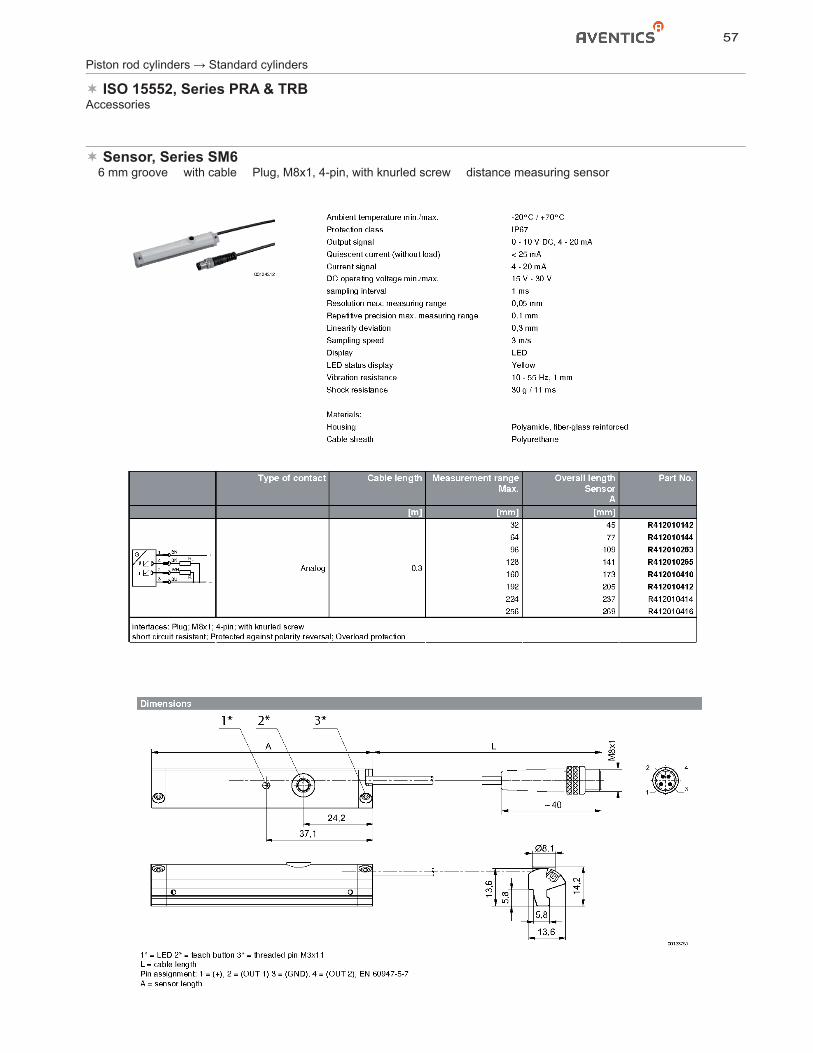
57
Piston rod cylinders → Standard cylinders
ISO 15552, Series PRA & TRBAccessories
Sensor, Series SM6� 6 mm groove � with cable � Plug, M8x1, 4-pin, with knurled screw � distance measuring sensor
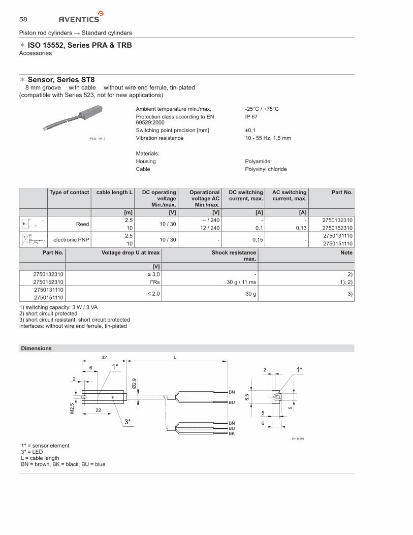
58
Sensor, Series ST8� 8 mm groove � with cable � without wire end ferrule, tin-plated(compatible with Series 523, not for new applications)
P322_194_2
Ambient temperature min./max. -25°C / +75°CProtection class according to EN 60529:2000
IP 67
Switching point precision [mm] ±0,1Vibration resistance 10 - 55 Hz, 1,5 mm
Materials:Housing PolyamideCable Polyvinyl chloride
Type of contact cable length L DC operating voltage
Min./max.
Operational voltage AC
Min./max.
DC switching current, max.
AC switching current, max.
Part No.
[m] [V] [V] [A] [A]
Reed2.5
10 / 30-- / 240 - - 2750132310
10 12 / 240 0.1 0,13 2750152310
electronic PNP2.5
10 / 30 - 0,15 -2750131110
10 2750151110Part No. Voltage drop U at Imax Shock resistance
max.Note
[V]2750132310 ≤ 3,0 - 2)2750152310 I*Rs 30 g / 11 ms 1); 2)2750131110
≤ 2,0 30 g 3)2750151110
1) switching capacity: 3 W / 3 VA2) short circuit protected3) short circuit resistant; short circuit protectedinterfaces: without wire end ferrule, tin-plated
Dimensions
M2,
5
2
6 1*
Ø2,
9
1*2
5
6
8,5
5
BN
BU
32 L
BNBUBK
22
3*
00134180
1* = sensor element3* = LEDL = cable lengthBN = brown, BK = black, BU = blue
Piston rod cylinders → Standard cylinders
ISO 15552, Series PRA & TRBAccessories
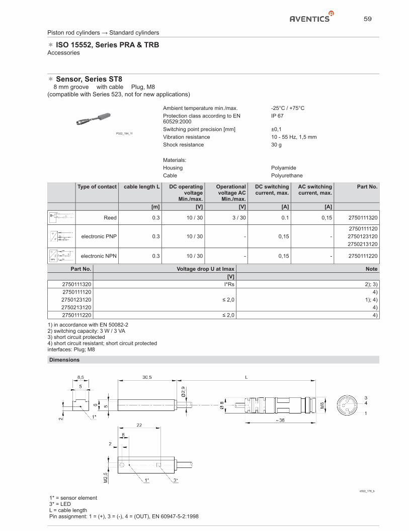
59
Piston rod cylinders → Standard cylinders
ISO 15552, Series PRA & TRBAccessories
Sensor, Series ST8� 8 mm groove � with cable � Plug, M8(compatible with Series 523, not for new applications)
P322_194_11
Ambient temperature min./max. -25°C / +75°CProtection class according to EN 60529:2000
IP 67
Switching point precision [mm] ±0,1Vibration resistance 10 - 55 Hz, 1,5 mmShock resistance 30 g
Materials:Housing PolyamideCable Polyurethane
Type of contact cable length L DC operating voltage
Min./max.
Operational voltage AC
Min./max.
DC switching current, max.
AC switching current, max.
Part No.
[m] [V] [V] [A] [A]
BN
BK RL
+ / – / ~
– / + / ~ Reed 0.3 10 / 30 3 / 30 0.1 0,15 2750111320
electronic PNP 0.3 10 / 30 - 0,15 -275011112027501231202750213120
BN
BK
BU
1
4
3
RL
+
–NPNelectronic NPN 0.3 10 / 30 - 0,15 - 2750111220
Part No. Voltage drop U at Imax Note[V]
2750111320 I*Rs 2); 3)2750111120
≤ 2,04)
2750123120 1); 4)2750213120 4)2750111220 ≤ 2,0 4)
1) in accordance with EN 50082-22) switching capacity: 3 W / 3 VA3) short circuit protected4) short circuit resistant; short circuit protectedinterfaces: Plug; M8
Dimensions
d322_178_b
1* = sensor element3* = LEDL = cable lengthPin assignment: 1 = (+), 3 = (-), 4 = (OUT), EN 60947-5-2:1998
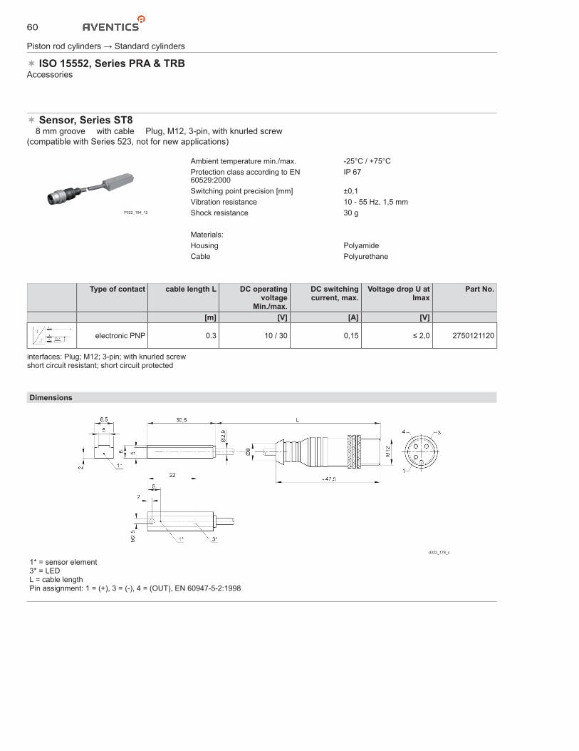
60
Dimensions
d322_178_c
1* = sensor element3* = LEDL = cable lengthPin assignment: 1 = (+), 3 = (-), 4 = (OUT), EN 60947-5-2:1998
Piston rod cylinders → Standard cylinders
ISO 15552, Series PRA & TRBAccessories
Sensor, Series ST8� 8 mm groove � with cable � Plug, M12, 3-pin, with knurled screw(compatible with Series 523, not for new applications)
P322_194_12
Ambient temperature min./max. -25°C / +75°CProtection class according to EN 60529:2000
IP 67
Switching point precision [mm] ±0,1Vibration resistance 10 - 55 Hz, 1,5 mmShock resistance 30 g
Materials:Housing PolyamideCable Polyurethane
Type of contact cable length L DC operating voltage
Min./max.
DC switchingcurrent, max.
Voltage drop U at Imax
Part No.
[m] [V] [A] [V]
electronic PNP 0.3 10 / 30 0,15 ≤ 2,0 2750121120
interfaces: Plug; M12; 3-pin; with knurled screwshort circuit resistant; short circuit protected
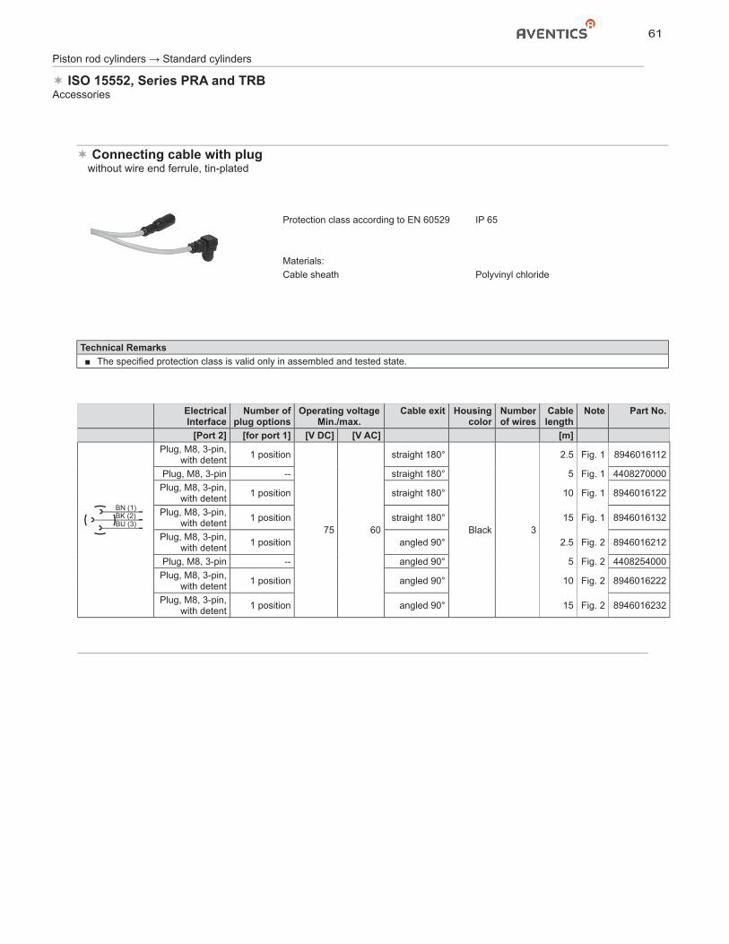
61
Piston rod cylinders → Standard cylinders
ISO 15552, Series PRA and TRBAccessories
ElectricalInterface
Number of plug options
Operating voltageMin./max.
Cable exit Housing color
Number of wires
Cable length
Note Part No.
[Port 2] [for port 1] [V DC] [V AC] [m]Plug, M8, 3-pin,
with detent 1 position
75 60
straight 180°
Black 3
2.5 Fig. 1 8946016112
Plug, M8, 3-pin -- straight 180° 5 Fig. 1 4408270000Plug, M8, 3-pin,
with detent 1 position straight 180° 10 Fig. 1 8946016122
Plug, M8, 3-pin, with detent 1 position straight 180° 15 Fig. 1 8946016132
Plug, M8, 3-pin, with detent 1 position angled 90° 2.5 Fig. 2 8946016212
Plug, M8, 3-pin -- angled 90° 5 Fig. 2 4408254000Plug, M8, 3-pin,
with detent 1 position angled 90° 10 Fig. 2 8946016222
Plug, M8, 3-pin, with detent 1 position angled 90° 15 Fig. 2 8946016232
Technical Remarks■ The specified protection class is valid only in assembled and tested state.
Connecting cable with plug� without wire end ferrule, tin-plated
Protection class according to EN 60529 IP 65
Materials:Cable sheath Polyvinyl chloride
BN (1)BK (2)BU (3)
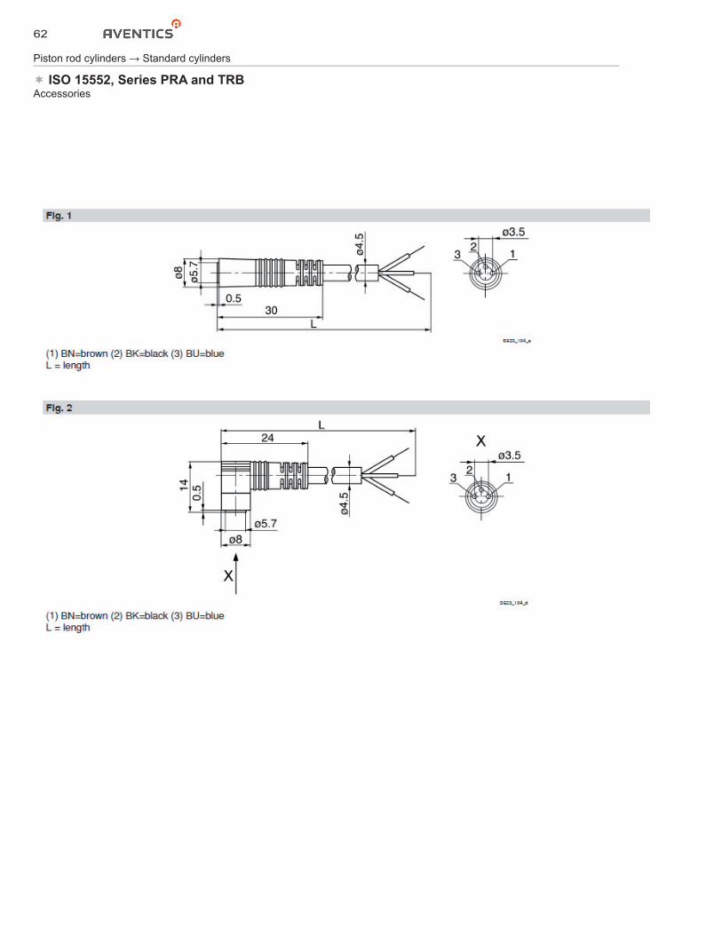
62
Piston rod cylinders → Standard cylinders
ISO 15552, Series PRA and TRBAccessories
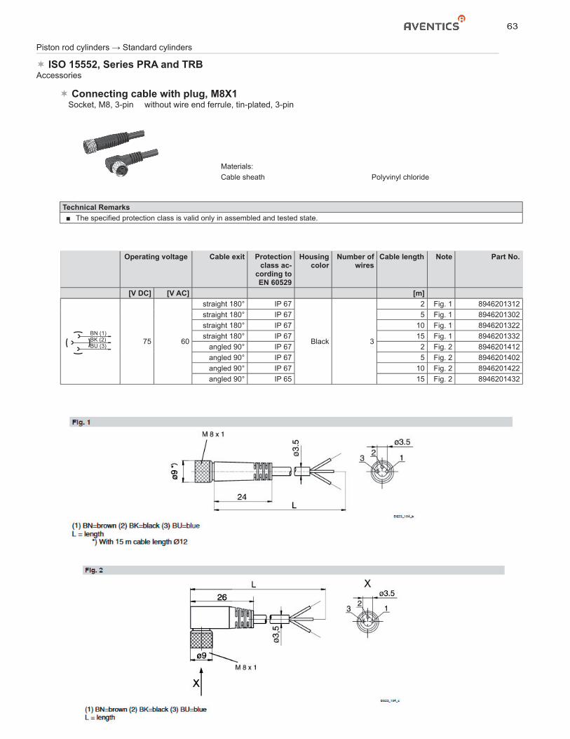
63
Piston rod cylinders → Standard cylinders
ISO 15552, Series PRA and TRBAccessories
Operating voltage Cable exit Protection class ac-
cording to EN 60529
Housing color
Number of wires
Cable length Note Part No.
[V DC] [V AC] [m]
75 60
straight 180° IP 67
Black 3
2 Fig. 1 8946201312straight 180° IP 67 5 Fig. 1 8946201302straight 180° IP 67 10 Fig. 1 8946201322straight 180° IP 67 15 Fig. 1 8946201332
angled 90° IP 67 2 Fig. 2 8946201412angled 90° IP 67 5 Fig. 2 8946201402angled 90° IP 67 10 Fig. 2 8946201422angled 90° IP 65 15 Fig. 2 8946201432
Technical Remarks■ The specified protection class is valid only in assembled and tested state.
Connecting cable with plug, M8X1� Socket, M8, 3-pin � without wire end ferrule, tin-plated, 3-pin
Materials:Cable sheath Polyvinyl chloride
BN (1)BK (2)BU (3)
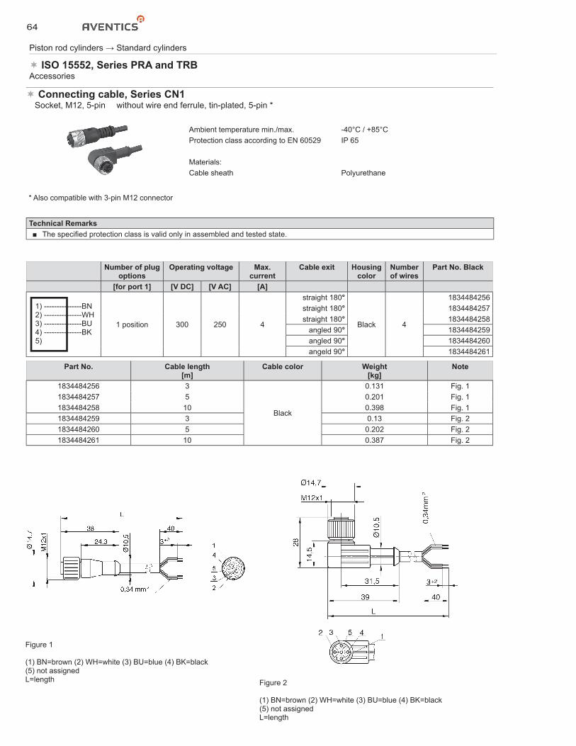
64
Piston rod cylinders → Standard cylinders
ISO 15552, Series PRA and TRBAccessories
Number of plugoptions
Operating voltage Max.current
Cable exit Housing color
Number of wires
Part No. Black
[for port 1] [V DC] [V AC] [A]
1) ---------------BN 2) ---------------WH 3) ---------------BU 4) ---------------BK 5)
1 position 300 250 4
straight 180°
Black 4
1834484256straight 180° 1834484257straight 180° 1834484258
angled 90° 1834484259angled 90° 1834484260angeld 90° 1834484261
Part No. Cable length[m]
Cable color Weight[kg]
Note
1834484256 3
Black
0.131 Fig. 11834484257 5 0.201 Fig. 11834484258 10 0.398 Fig. 11834484259 3 0.13 Fig. 21834484260 5 0.202 Fig. 21834484261 10 0.387 Fig. 2
Connecting cable, Series CN1� Socket, M12, 5-pin � without wire end ferrule, tin-plated, 5-pin *
Ambient temperature min./max. -40°C / +85°CProtection class according to EN 60529 IP 65
Materials:Cable sheath Polyurethane
* Also compatible with 3-pin M12 connector
Technical Remarks■ The specified protection class is valid only in assembled and tested state.
Figure 1
(1) BN=brown (2) WH=white (3) BU=blue (4) BK=black(5) not assignedL=length Figure 2
(1) BN=brown (2) WH=white (3) BU=blue (4) BK=black(5) not assignedL=length
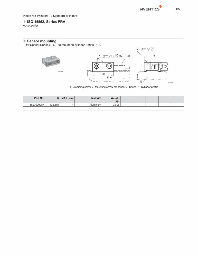
65
Piston rod cylinders → Standard cylinders
ISO 15552, Series PRAAccessories
Sensor mounting� for Sensor Series ST6 � to mount on cylinder Series PRA
00105962
2030,6
16
7,3
MA121) 3)
4)
2)
00104951
1) Clamping screw 2) Mounting screw for sensor 3) Sensor 4) Cylinder profile
Part No. 1) MA1 [Nm] Material Weight[kg]
1827020287 M2,5x5 1 Aluminum 0.006
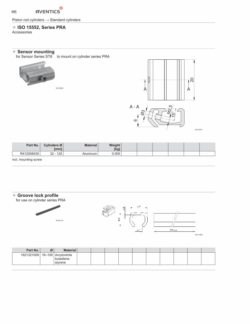
66
Piston rod cylinders → Standard cylinders
ISO 15552, Series PRAAccessories
Sensor mounting� for Sensor Series ST8 � to mount on cylinder series PRA
00133850
20
AA
6
Ø3
15°M
2,5A - A
00133781
Part No. Cylinders Ø[mm]
Material Weight[kg]
R412008435 32 - 125 Aluminum 0.005
incl. mounting screw
Groove lock profile� for use on cylinder series PRA
00105175
00111999
Part No. Ø Material1821321009 16–100 Acrylonitrile
butadiene styrene
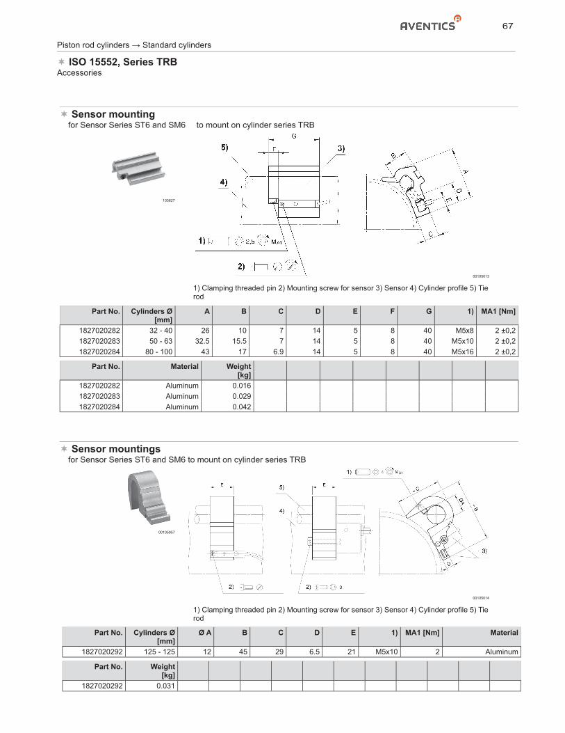
67
Piston rod cylinders → Standard cylinders
ISO 15552, Series TRBAccessories
Sensor mountings� for Sensor Series ST6 and SM6 to mount on cylinder series TRB
00105957
00105014
1) Clamping threaded pin 2) Mounting screw for sensor 3) Sensor 4) Cylinder profile 5) Tie rod
Part No. Cylinders Ø[mm]
Ø A B C D E 1) MA1 [Nm] Material
1827020292 125 - 125 12 45 29 6.5 21 M5x10 2 Aluminum
Part No. Weight[kg]
1827020292 0.031
Sensor mounting� for Sensor Series ST6 and SM6 � to mount on cylinder series TRB
103627
00105013
1) Clamping threaded pin 2) Mounting screw for sensor 3) Sensor 4) Cylinder profile 5) Tie rod
Part No. Cylinders Ø[mm]
A B C D E F G 1) MA1 [Nm]
1827020282 32 - 40 26 10 7 14 5 8 40 M5x8 2 ±0,21827020283 50 - 63 32.5 15.5 7 14 5 8 40 M5x10 2 ±0,21827020284 80 - 100 43 17 6.9 14 5 8 40 M5x16 2 ±0,2
Part No. Material Weight[kg]
1827020282 Aluminum 0.0161827020283 Aluminum 0.0291827020284 Aluminum 0.042
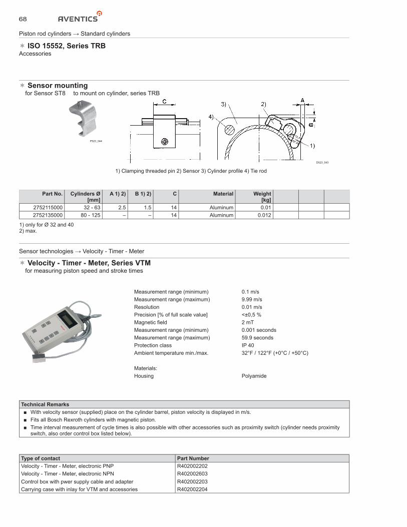
68
Piston rod cylinders → Standard cylinders
ISO 15552, Series TRBAccessories
Sensor mounting� for Sensor ST8 � to mount on cylinder, series TRB
P523_044
D523_043
1) Clamping threaded pin 2) Sensor 3) Cylinder profile 4) Tie rod
Part No. Cylinders Ø[mm]
A 1) 2) B 1) 2) C Material Weight[kg]
2752115000 32 - 63 2.5 1.5 14 Aluminum 0.012752135000 80 - 125 – – 14 Aluminum 0.012
1) only for Ø 32 and 402) max.
Technical Remarks■ With velocity sensor (supplied) place on the cylinder barrel, piston velocity is displayed in m/s.■ Fits all Bosch Rexroth cylinders with magnetic piston.■ Time interval measurement of cycle times is also possible with other accessories such as proximity switch (cylinder needs proximity
switch, also order control box listed below).
Sensor technologies → Velocity - Timer - Meter
Velocity - Timer - Meter, Series VTM� for measuring piston speed and stroke times
Measurement range (minimum) 0.1 m/sMeasurement range (maximum) 9.99 m/sResolution 0.01 m/sPrecision [% of full scale value] <±0,5 %Magnetic field 2 mTMeasurement range (minimum) 0.001 secondsMeasurement range (maximum) 59.9 secondsProtection class IP 40Ambient temperature min./max. 32°F / 122°F (+0°C / +50°C)
Materials:Housing Polyamide
Type of contact Part NumberVelocity - Timer - Meter, electronic PNP R402002202Velocity - Timer - Meter, electronic NPN R402002603Control box with pwer supply cable and adapter R402002203Carrying case with inlay for VTM and accessories R402002204
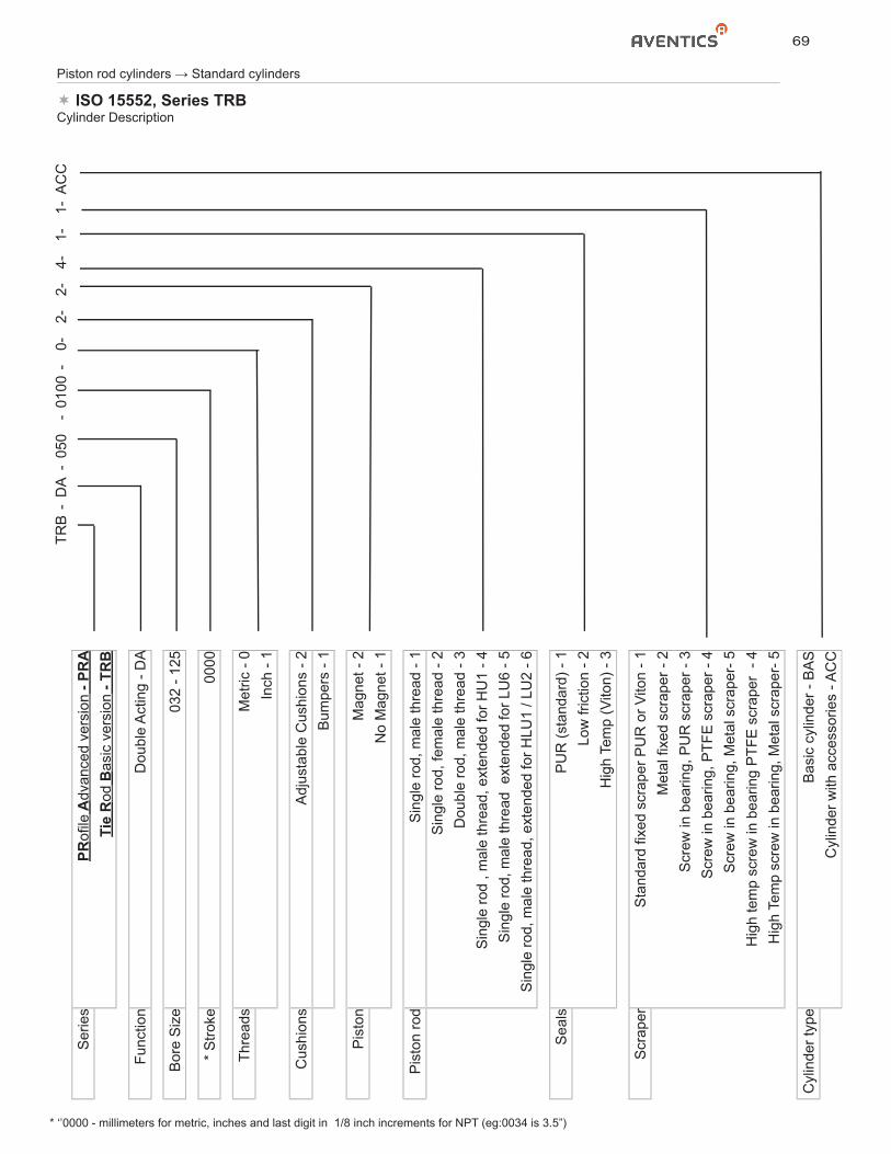
69
Piston rod cylinders → Standard cylinders
ISO 15552, Series TRBCylinder Description
TRB
-D
A-
050
-01
00-
0-2-
2-4-
1-1-
AC
CS
erie
sPR
ofile
Adv
ance
d ve
rsio
n - P
RA
Tie
Rod
Bas
ic v
ersi
on -
TRB
Func
tion
Dou
ble
Act
ing
- DA
Bor
e S
ize
032
- 125
* S
troke
0000
Thre
ads
Met
ric -
0In
ch -
1
Cus
hion
sA
djus
tabl
e C
ushi
ons
- 2B
umpe
rs -
1
Pis
ton
Mag
net -
2N
o M
agne
t - 1
Pis
ton
rod
Sin
gle
rod,
mal
e th
read
- 1
Sin
gle
rod,
fem
ale
thre
ad -
2D
oubl
e ro
d, m
ale
thre
ad -
3S
ingl
e ro
d , m
ale
thre
ad, e
xten
ded
for H
U1
- 4S
ingl
e ro
d, m
ale
thre
ad e
xten
ded
for L
U6
- 5S
ingl
e ro
d, m
ale
thre
ad, e
xten
ded
for H
LU1
/ LU
2 - 6
Sea
lsP
UR
(sta
ndar
d) -
1Lo
w fr
ictio
n - 2
Hig
h Te
mp
(Vito
n) -
3
Scr
aper
Sta
ndar
d fix
ed s
crap
er P
UR
or V
iton
- 1M
etal
fixe
d sc
rape
r - 2
Scr
ew in
bea
ring,
PU
R s
crap
er -
3S
crew
in b
earin
g, P
TFE
scr
aper
- 4
Scr
ew in
bea
ring,
Met
al s
crap
er- 5
Hig
h te
mp
scre
w in
bea
ring
PTF
E s
crap
er -
4H
igh
Tem
p sc
rew
in b
earin
g, M
etal
scr
aper
- 5
Cyl
inde
r typ
eB
asic
cyl
inde
r - B
AS
Cyl
inde
r with
acc
esso
ries
- AC
C
* ‘’0000 - millimeters for metric, inches and last digit in 1/8 inch increments for NPT (eg:0034 is 3.5”)
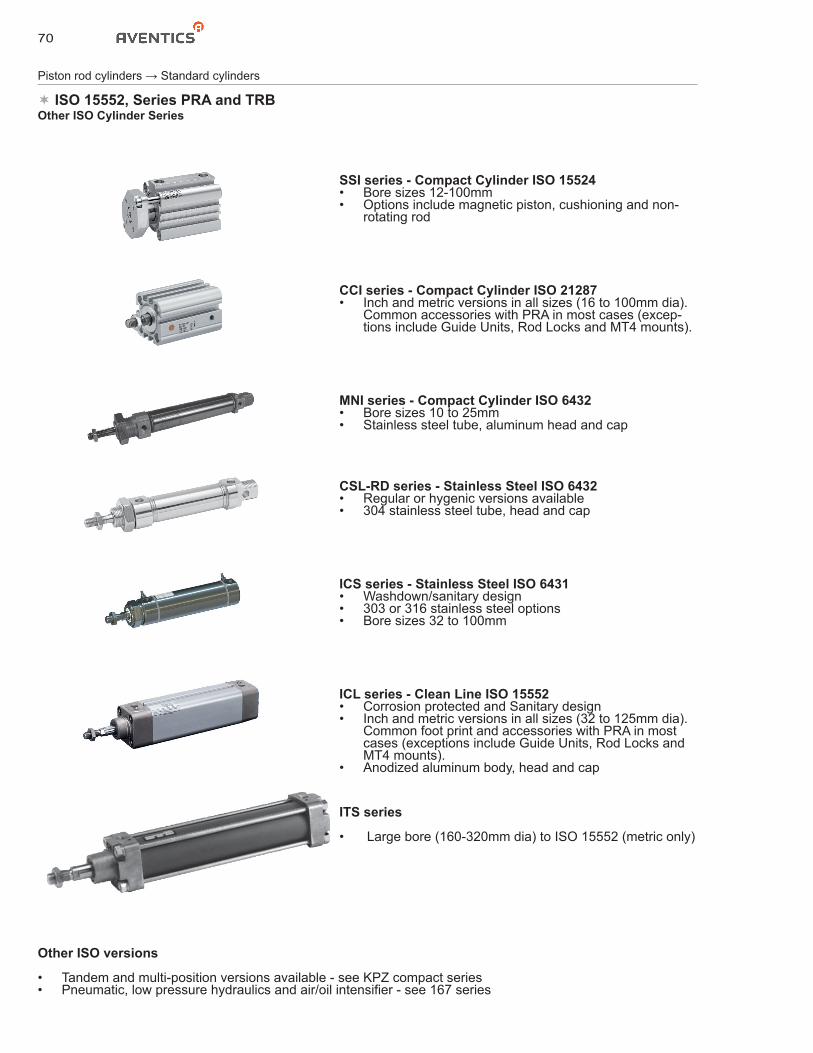
70
Piston rod cylinders → Standard cylinders
ISO 15552, Series PRA and TRBOther ISO Cylinder Series
SSI series - Compact Cylinder ISO 15524• Bore sizes 12-100mm• Options include magnetic piston, cushioning and non-
rotating rod
CCI series - Compact Cylinder ISO 21287• Inch and metric versions in all sizes (16 to 100mm dia).
Common accessories with PRA in most cases (excep-tions include Guide Units, Rod Locks and MT4 mounts).
MNI series - Compact Cylinder ISO 6432• Bore sizes 10 to 25mm• Stainless steel tube, aluminum head and cap
CSL-RD series - Stainless Steel ISO 6432• Regular or hygenic versions available• 304 stainless steel tube, head and cap
ICS series - Stainless Steel ISO 6431• Washdown/sanitary design• 303 or 316 stainless steel options • Bore sizes 32 to 100mm
ICL series - Clean Line ISO 15552• Corrosion protected and Sanitary design • Inch and metric versions in all sizes (32 to 125mm dia).
Common foot print and accessories with PRA in most cases (exceptions include Guide Units, Rod Locks and MT4 mounts).
• Anodized aluminum body, head and cap
ITS series
• Large bore (160-320mm dia) to ISO 15552 (metric only)
Other ISO versions
• Tandem and multi-position versions available - see KPZ compact series• Pneumatic, low pressure hydraulics and air/oil intensifier - see 167 series
1. WARNING: FLUID MEDIA
AVENTICS pneumatic devices are designed and tested for use with filtered, clean, dry, chemical free air at pressures and temperatures within the specified limits of the device. For use with media other than air or for human life support systems, AVENTICS must be consulted. Hydraulic cylinders are designed for operation with filtered, clean, petroleum based hydraulic fluid; operation using fire-resistant or other special types of fluids may require special packing and seals. Consult the factory.
2. WARNING: MATERIAL COMPATIBILITY
Damage to product seals or other parts caused by the use of non-compatible lubricants, oil additives or synthetic lubricants in the air system compressor or line lubrication devices voids the AVENTICS warranty and can result in product failure or other malfunction. See lubrication recommendations below.
AIR LINE LUBRICANTS! In service higher than 18 cycles per minute or with continuous flow of air through the device, an air line lubricator is recommended.* (Do not use line lubrication with vacuum products.) However, the lubricator must be maintained since the oil will wash out the grease, and lack of lubrication will greatly shorten the life expectancy. The oils used in the lubricator must be compatible with the elastomers in the device. The elastomers are normally BUNA-N, NEOPRENE, VITON, SILICONE and HYTREL. AVENTICS recommends the use of only petroleum based oils without synthetic additives, and with an aniline point between 180° F and 210° F.
COMPRESSOR LUBRICANTS! All compressors (with the exception of special "oil free" units) pass oil mist or vapor from the internal crankcase lubricating system through to the compressed air. Since even small amounts of non-compatible lubricants can cause severe seal deterioration (which could result in component and system failure) special care should be taken in selecting compatible compressor lubricants.
3. WARNING: INSTALLATION AND MOUNTING
The user of these devices must conform to all applicable electrical, mechanical, piping and other codes in the installation, operation or repair of these devices.
INSTALLATION! Do not attempt to install, operate or repair these devices without proper training in the technique of working on pneumatic or hydraulic systems and devices, unless under trained supervision. Compressed air and hydraulic systems contain high levels of stored energy. Do not attempt to connect, disconnect or repair these products
when a system is under pressure. Always exhaust or drain the pressure from a system before performing any service work. Failure to do so can result in serious personal injury.
MOUNTING! Devices should be mounted and positioned in such a manner that they cannot be accidentally operated.
4. WARNING: APPLICATION AND USE OF PRODUCTS
The possibility does exist for any device or accessory to fail to operate properly through misuse, wear or malfunction. The user must consider these possibilities and should provide appropriate safe guards in the application or system design to prevent personal injury or property damage in the event of a malfunction.
5. WARNING: CONVERSION, MAINTENANCE AND REPAIR
When a device is disassembled for conversion to a different configuration, maintenance or repair, the device must be tested for leakage and proper operation after being reassembled and prior to installation.
MAINTENANCE AND REPAIR! Maintenance periods should be scheduled in accordance with frequency of use and working conditions. All AVENTICS products should provide a minimum of 1,000,000 cycles of maintenance free service when used and lubricated as recommended. However, these products should be visually inspected for defects and given an "in system" operating performance and leakage test once a year. Where devices require a major repair as a result of the one million cycles, one year, or routine inspection, the device must be disassembled, cleaned, inspected, parts replaced as required, rebuilt and tested for leakage and proper operation prior to installation. See individual catalogs for specific cycle life estimates.
6. PRODUCT CHANGES
Product changes including specifications, features, designs and availability are subject to change at any time without notice. For critical dimensions or specifications, contact factory.
*Many AVENTICS pneumatic valves and cylinders can operate with or without air line lubrication; see individual sales catalogs for details.
-Refer to the appropriate service manual for parts and service information, most are available for download from www.aventics.com/us/downloads
NOTICE TO PRODUCT USERS
WARRANTIES7.1 Emerson warrants that:a) Emerson will transfer title to the Goods (excluding Software and Firmware) to Customer under Clause 4 of our Terms and Conditions of Sale*;b) Goods, Documentation and Services will conform with the Specification; c) Goods made by Emerson or its Affiliates will, under normal use and care, be free from defects in materials or workmanship; andd) Emerson and its Affiliates’ Personnel delivering Services are trained and will use reasonable skill and care. 7.2 Warranty Periods. Unless otherwise specified by Emerson, the warranties in Clause 7.1 apply as follows:a) Goods: until the earlier of 12 months from the first installation or 18 months from delivery (90 days from delivery in the case of consumables); b) Services: for 90 days from completion of the Services; c) Goods repaired, replacement items and Services re-performed: from delivery of the replacement or completion of the repair or re-performance, for 90 days or until the end of the original warranty period (if later). 7.3 Warranty Procedure. Clause 7.3 applies if, within the warranty period, Customer discovers any non-conformity with a warranty in Clause 7.1, tells Emerson in writing and, in the case of Goods, returns the non-conforming items at Customer’s cost, freight and insurance pre-paid, to the repair facility chosen by Emerson. Where this Clause applies, Emerson will, at its sole option, either:a) correct any non-conforming Documents and Services; or b) repair or replace non-conforming Goods FCA (Incoterms® 2010) at the repair location; or c) instead refund the price of the non-conforming item.7.4 Exclusions from Warranty. a) The warranties in Clause 7.1(b), (c) and (d) exclude and Customer will pay the cost of all repairs and replacements caused by any of the following: normal wear and use; inadequate maintenance; unsuitable power sources or environmental conditions; improper handling, storage, installation, or operation; misuse or accident caused by anybody except Emerson; a modification or repair not approved by Emerson in writing; materials or workmanship made, provided or specified by Customer; contamination; the use of unapproved parts, firmware or software; Cyber Attack; any other cause not the fault of Emerson.b) Emerson will not pay any costs relating to non-compliance with a warranty in Clause 7.1, except where agreed in writing in advance. Unless accepted in writing by Emerson, Customer will pay: (i) all costs of dismantling, freight, reinstallation and the time and expenses of Emerson Personnel for travel under Clause 7; and (ii) all costs incurred by Emerson in correcting nonconformities for which Emerson is not responsible under Clause 7 and in examining items that comply with the warranties in Clause 7.1.c) If Emerson relies on wrong or incomplete information supplied by Customer, all warranties are void unless Emerson agrees otherwise in writing.d) Customer alone is responsible for the selection, maintenance and use of the Goods.e) Resale Products carry only the warranty given by the original manufacturer. Emerson has no liability for Resale Products beyond making a reasonable commercial effort to arrange procurement and shipping of the Resale Products.7.5 Disclaimer. The limited warranties set out in this Clause 7 are the only warranties made by Emerson and can be changed only with Emerson’s signed written agreement. THE WARRANTIES AND REMEDIES IN CLAUSE 7 ARE EXCLUSIVE. THERE ARE NO REPRESENTATIONS OR WARRANTIES OF ANY KIND, EXPRESS OR IMPLIED, ABOUT MERCHANTABILITY, FITNESS FOR PARTICULAR PURPOSE OR ANYTHING ELSE FOR ANY OF THE GOODS, DOCUMENTATION OR SERVICES.
*Additional conditions apply - for full details, visit our website to download our Terms and Conditions of Sale:For U.S.: www.aventics.com/us/downloads | For Canada: www.aventics.com/ca | (AVENTICS Corporation is owned by Emerson Electric Co.)
AVENTICS Corporation1953 Mercer Road
Lexington, KY 40511
Tel 859.254.8031
Fax 800.489.1488
www.aventics.com/us
Further contacts:
www.aventics.com/en/contact
The data specified only serve to
describe the product. No statements
concerning a certain condition or
suitability for a certain application
can be derived from our information.
The information given does not re-
lease the user from the obligation of
own judgment and verification. It
must be remembered that our
products are subject to a natural
process of wear and aging.
SC-200.75 2018-12 Subject to change. Printed in USA. © AVENTICS Corporation
This document, as well as the data, specifications and other information set forth in it, are the exclusive
property of AVENTICS. It may not be reproduced or given to third parties without its consent.
AVENTICS Incorporated5515 North Service RdSuite #104Burlington, Ontario L7L 6G4Tel 905.332.0399Fax 905.332.8596www.aventics.com/[email protected]
AVENTICS México, S. de R.L. de C.V.AV. Paseo de la Reforma 250, Esquina Niza Deleg. Cuauhtémoc06280 México, D.F.Tel 866.873.0635www.aventics.com/[email protected]