Embed Size (px)
Citation preview
www.paharpur.com
SERIESOXF-30K
INDUCED DRAUGHT CROSSFLOW FRPCOOLING TOWER
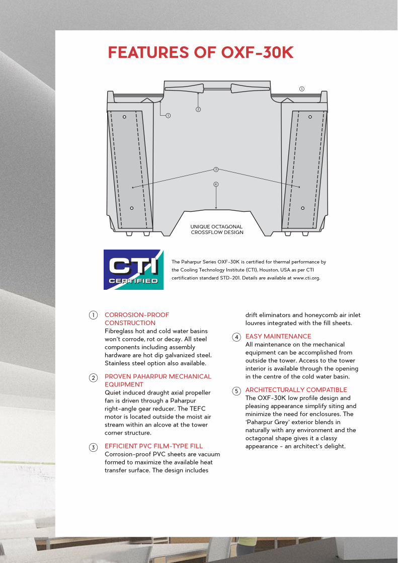
UNIQUE OCTAGONAL CROSSFLOW DESIGN
The Paharpur Series OXF-30K is certified for thermal performance by
the Cooling Technology Institute (CTI), Houston, USA as per CTI
certification standard STD-201. Details are available at www.cti.org.
FEATURES OF OXF-30K
CORROSION-PROOF
CONSTRUCTION
Fibreglass hot and cold water basins
won’t corrode, rot or decay. All steel
components including assembly
hardware are hot dip galvanized steel.
Stainless steel option also available.
PROVEN PAHARPUR MECHANICAL
EQUIPMENT
Quiet induced draught axial propeller
fan is driven through a Paharpur
right-angle gear reducer. The TEFC
motor is located outside the moist air
stream within an alcove at the tower
corner structure.
EFFICIENT PVC FILM-TYPE FILL
Corrosion-proof PVC sheets are vacuum
formed to maximize the available heat
transfer surface. The design includes
drift eliminators and honeycomb air inlet
louvres integrated with the fill sheets.
EASY MAINTENANCE
All maintenance on the mechanical
equipment can be accomplished from
outside the tower. Access to the tower
interior is available through the opening
in the centre of the cold water basin.
ARCHITECTURALLY COMPATIBLE
The OXF-30K low profile design and
pleasing appearance simplify siting and
minimize the need for enclosures. The
‘Paharpur Grey’ exterior blends in
naturally with any environment and the
octagonal shape gives it a classy
appearance - an architect’s delight.
1
4
5
2
3
1
2
3
4
5
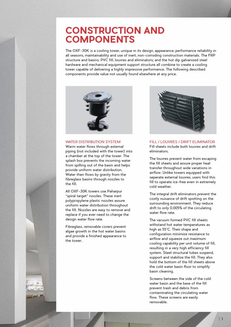
FILL / LOUVRES / DRIFT ELIMINATOR
Fill sheets include both louvres and drift
eliminators.
The louvres prevent water from escaping
the fill sheets and assure proper heat
transfer throughout wide variations in
airflow. Unlike towers equipped with
seperate external louvres, users find this
fill to operate ice-free even in extremely
cold weather.
The integral drift eliminators prevent the
costly nuisance of drift spotting on the
surrounding environment. They reduce
drift to only 0.005% of the circulating
water flow rate.
The vacuum formed PVC fill sheets
withstand hot water temperatures as
high as 55°C. Their shape and
configuration minimize resistance to
airflow and squeeze out maximum
cooling capability per unit volume of fill,
resulting in a very high efficiency fill
system. Steel structural tubes suspend,
support and stabilize the fill. They also
hold the bottom of the fill sheets above
the cold water basin floor to simplify
basin cleaning.
Screens between the side of the cold
water basin and the base of the fill
prevent trash and debris from
contaminating the circulating water
flow. These screens are easily
removable.
WATER DISTRIBUTION SYSTEM
Warm water flows through external
piping (not included with the tower) into
a chamber at the top of the tower. The
splash box prevents the incoming water
from spilling out of the basin and helps
provide uniform water distribution.
Water then flows by gravity from the
fibreglass basins through nozzles to
the fill.
All OXF-30K towers use Paharpur
“spiral target” nozzles. These inert
polypropylene plastic nozzles assure
uniform water distribution throughout
the fill. Nozzles are easy to remove and
replace if you ever need to change the
design water flow rate.
Fibreglass, removable covers prevent
algae growth in the hot water basins
and provide a finished appearance to
the tower.
CONSTRUCTION AND COMPONENTSThe OXF-30K is a cooling tower, unique in its design, appearance, performance reliability in
all seasons, maintainability and use of inert, non-corroding construction materials. The FRP
structure and basins; PVC fill, louvres and eliminators; and the hot dip galvanized steel
hardware and mechanical equipment support structure all combine to create a cooling
tower capable of delivering a highly impressive performance. The following described
components provide value not usually found elsewhere at any price.
1
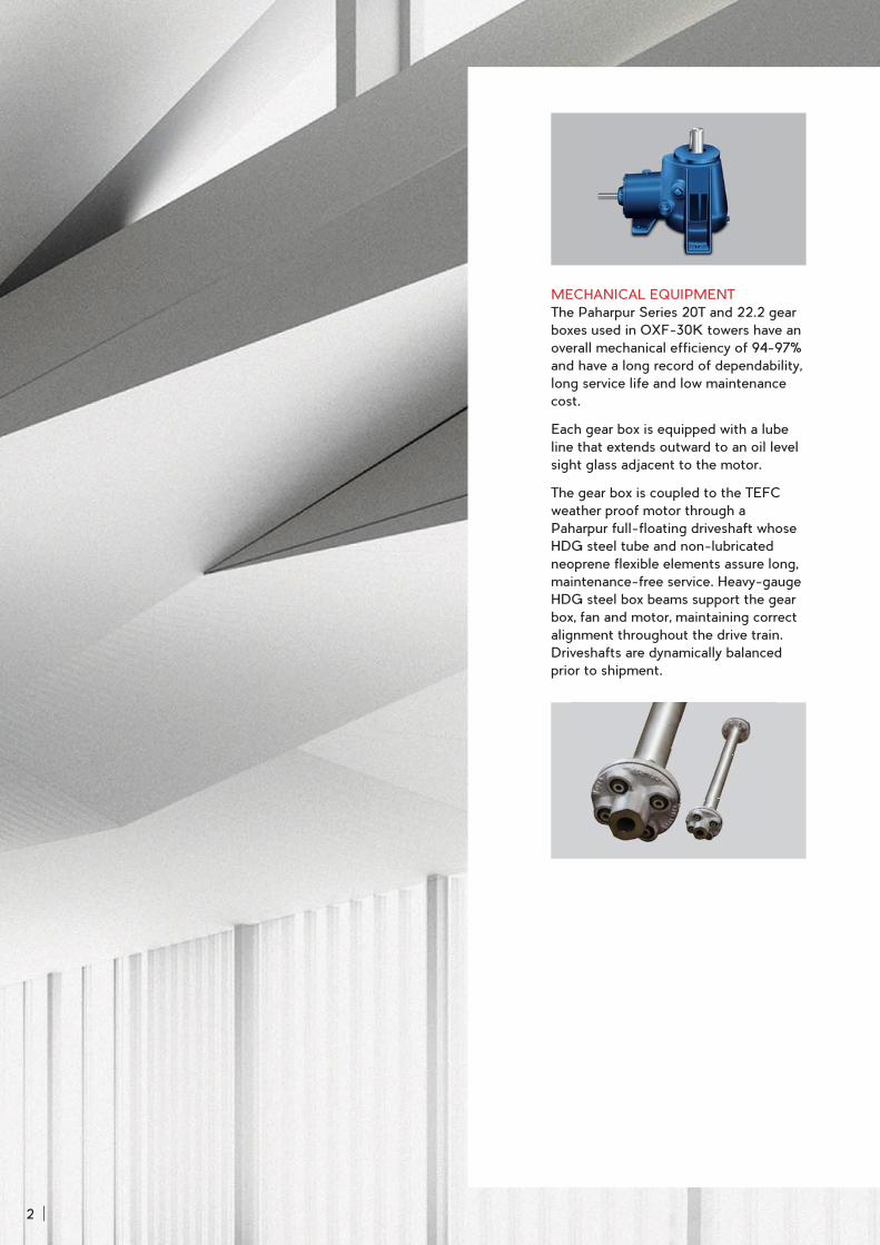
MECHANICAL EQUIPMENT
The Paharpur Series 20T and 22.2 gear
boxes used in OXF-30K towers have an
overall mechanical efficiency of 94-97%
and have a long record of dependability,
long service life and low maintenance
cost.
Each gear box is equipped with a lube
line that extends outward to an oil level
sight glass adjacent to the motor.
The gear box is coupled to the TEFC
weather proof motor through a
Paharpur full-floating driveshaft whose
HDG steel tube and non-lubricated
neoprene flexible elements assure long,
maintenance-free service. Heavy-gauge
HDG steel box beams support the gear
box, fan and motor, maintaining correct
alignment throughout the drive train.
Driveshafts are dynamically balanced
prior to shipment.
2
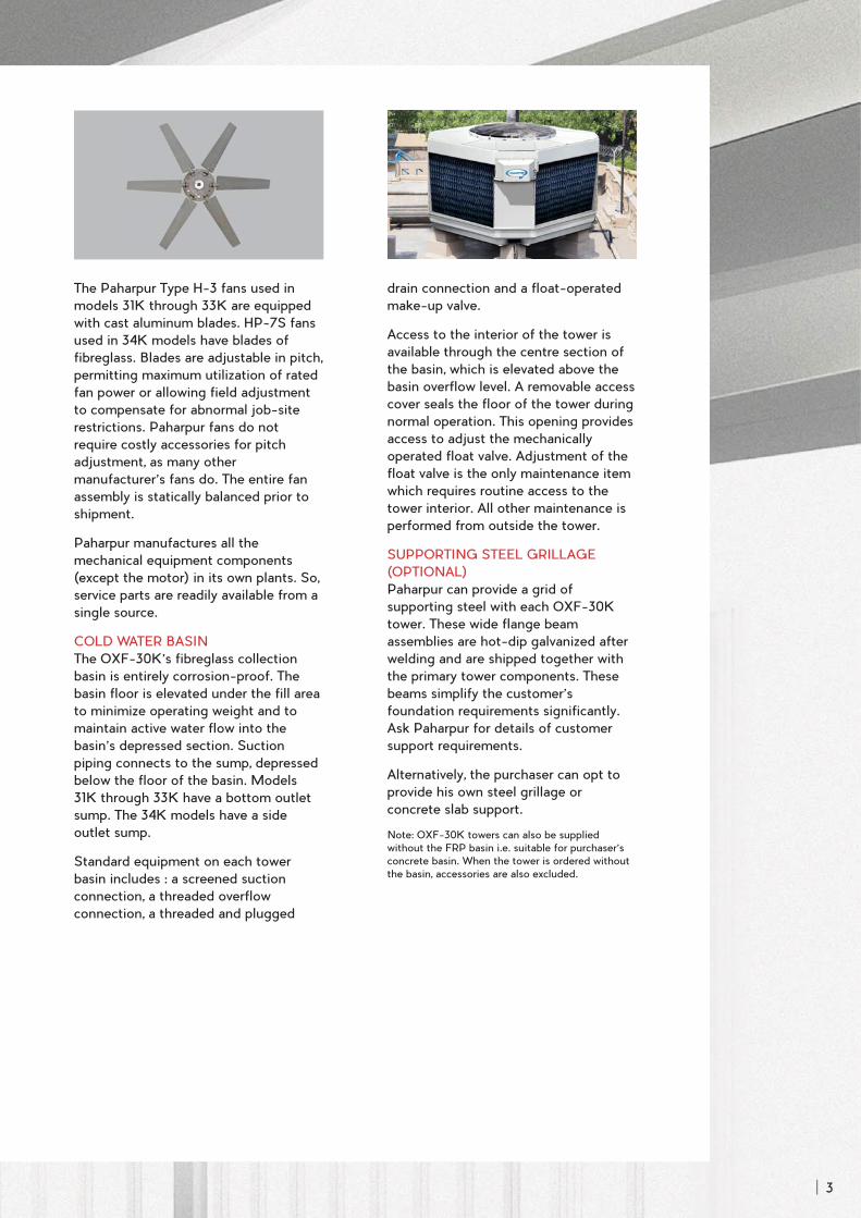
The Paharpur Type H-3 fans used in
models 31K through 33K are equipped
with cast aluminum blades. HP-7S fans
used in 34K models have blades of
fibreglass. Blades are adjustable in pitch,
permitting maximum utilization of rated
fan power or allowing field adjustment
to compensate for abnormal job-site
restrictions. Paharpur fans do not
require costly accessories for pitch
adjustment, as many other
manufacturer’s fans do. The entire fan
assembly is statically balanced prior to
shipment.
Paharpur manufactures all the
mechanical equipment components
(except the motor) in its own plants. So,
service parts are readily available from a
single source.
COLD WATER BASIN
The OXF-30K’s fibreglass collection
basin is entirely corrosion-proof. The
basin floor is elevated under the fill area
to minimize operating weight and to
maintain active water flow into the
basin’s depressed section. Suction
piping connects to the sump, depressed
below the floor of the basin. Models
31K through 33K have a bottom outlet
sump. The 34K models have a side
outlet sump.
Standard equipment on each tower
basin includes : a screened suction
connection, a threaded overflow
connection, a threaded and plugged
drain connection and a float-operated
make-up valve.
Access to the interior of the tower is
available through the centre section of
the basin, which is elevated above the
basin overflow level. A removable access
cover seals the floor of the tower during
normal operation. This opening provides
access to adjust the mechanically
operated float valve. Adjustment of the
float valve is the only maintenance item
which requires routine access to the
tower interior. All other maintenance is
performed from outside the tower.
SUPPORTING STEEL GRILLAGE
(OPTIONAL)
Paharpur can provide a grid of
supporting steel with each OXF-30K
tower. These wide flange beam
assemblies are hot-dip galvanized after
welding and are shipped together with
the primary tower components. These
beams simplify the customer’s
foundation requirements significantly.
Ask Paharpur for details of customer
support requirements.
Alternatively, the purchaser can opt to
provide his own steel grillage or
concrete slab support.
Note: OXF-30K towers can also be supplied
without the FRP basin i.e. suitable for purchaser’s
concrete basin. When the tower is ordered without
the basin, accessories are also excluded.
3
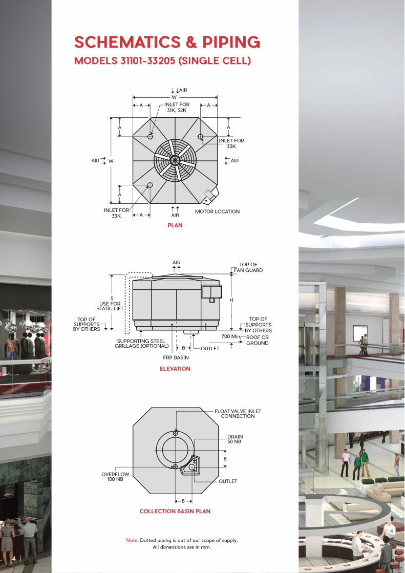
SCHEMATICS & PIPINGMODELS 31101-33205 (SINGLE CELL)
COLLECTION BASIN PLAN
B
B
OUTLET
OVERFLOW100 NB
FLOAT VALVE INLETCONNECTION
DRAIN50 NB
PLAN
MOTOR LOCATION
W
W
INLET FOR31K, 32K
INLET FOR33K
INLET FOR33K
AIR
AIR
AIRAIR
A
A
A
A
A
A
ELEVATION
Note: Dotted piping is out of our scope of supply.
All dimensions are in mm.
4
USE FORSTATIC LIFT
TOP OFSUPPORTSBY OTHERS
SUPPORTING STEEL GRILLAGE (OPTIONAL)
OUTLET
S
B
H
TOP OFFAN GUARD
FRP BASIN
TOP OFSUPPORTSBY OTHERS
ROOF ORGROUND
700 Min
AIR
Note:
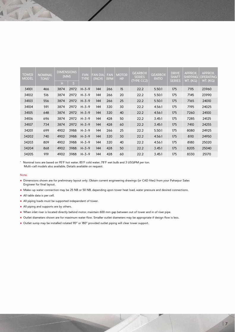
Dimensions shown are for preliminary layout only. Obtain current engineering drawings (or CAD files) from your Paharpur Sales
Engineer for final layout.
Make-up water connection may be 25 NB or 50 NB, depending upon tower heat load, water pressure and desired connections.
All table data is per cell.
31K and 32K models require only one inlet per cell and inlet piping may be located at any of the four tower corners. 33K models whose
design water flow is 2025 USGPM per cell or less may use a single 250 NB inlet. Add 50 mm to “S” dimensions. Above 2025 USGPM
per cell, two 200 NB inlets are required, located 180O apart.
All piping loads must be supported independent of tower.
All piping and supports are by others.
When inlet riser is located directly behind motor, maintain 600 mm gap between out of tower and in of riser pipe.
Outlet diameters shown are for maximum water flow. Smaller outlet diameters may be appropriate if design flow is less.
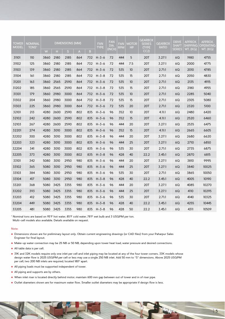
* Nominal tons are based on 95°F hot water, 85°F cold water, 78°F wet bulb and 3 USGPM per ton.
Multi-cell models also available. Details available on request.
W H S A B
TOWER MODEL
NOMINAL TONS*
FAN TYPE
FAN DIA.
(INCH)
FAN RPM
MOTOR HP
GEARBOX SERIES(TYPE CC2)
GEARBOX RATIO
DRIVESHAFT SERIES
DIMENSIONS (MM) APPROX. SHIPPING WT. (KG)
APPROX. OPERATING
WT. (KG)
31101 110 3860 2180 2185 864 732 H-3-6 72 444 5 20T 3.27:1 6Q 1980 4755
31102 125 3860 2180 2185 864 732 H-3-6 72 444 7.5 20T 3.27:1 6Q 2000 4775
31103 139 3860 2180 2185 864 732 H-3-6 72 535 10 20T 2.71:1 6Q 2010 4785
31104 161 3860 2180 2185 864 732 H-3-8 72 535 15 20T 2.71:1 6Q 2050 4830
31201 163 3860 2565 2590 864 732 H-3-6 72 535 10 20T 2.71:1 6Q 2135 4915
31202 185 3860 2565 2590 864 732 H-3-8 72 535 15 20T 2.71:1 6Q 2180 4955
31301 179 3860 2980 3000 864 732 H-3-6 72 535 10 20T 2.71:1 6Q 2285 5040
31302 204 3860 2980 3000 864 732 H-3-8 72 535 15 20T 2.71:1 6Q 2305 5080
31303 225 3860 2980 3000 864 732 H-3-6 72 535 20 20T 2.71:1 6Q 2320 5100
32101 213 4280 2600 2590 802 835 H-3-6 96 352 10 20T 4.11:1 6Q 2480 6420
32102 242 4280 2600 2590 802 835 H-3-6 96 352 15 20T 4.11:1 6Q 2520 6460
32103 267 4280 2600 2590 802 835 H-3-6 96 444 20 20T 3.27:1 6Q 2535 6475
32201 274 4280 3010 3000 802 835 H-3-6 96 352 15 20T 4.11:1 6Q 2665 6605
32202 300 4280 3010 3000 802 835 H-3-8 96 444 20 20T 3.27:1 6Q 2680 6620
32203 323 4280 3010 3000 802 835 H-3-6 96 444 25 20T 3.27:1 6Q 2710 6850
32204 341 4280 3010 3000 802 835 H-3-6 96 535 30 20T 2.71:1 6Q 2735 6875
32205 373 4280 3010 3000 802 835 H-3-8 96 428 40 22.2 3.45:1 6Q 2870 6815
33101 342 5080 3010 2950 980 835 H-3-6 96 444 20 20T 3.27:1 6Q 3810 9995
33102 365 5080 3010 2950 980 835 H-3-6 96 444 25 20T 3.27:1 6Q 3840 10025
33103 384 5080 3010 2950 980 835 H-3-6 96 535 30 20T 2.71:1 6Q 3865 10050
33104 417 5080 3010 2950 980 835 H-3-8 96 428 40 22.2 3.45:1 6Q 4005 10190
33201 368 5080 3425 3355 980 835 H-3-6 96 444 20 20T 3.27:1 6Q 4085 10270
33202 393 5080 3425 3355 980 835 H-3-6 96 444 25 20T 3.27:1 6Q 4110 10295
33203 412 5080 3425 3355 980 835 H-3-6 96 535 30 20T 2.71:1 6Q 4140 10325
33204 449 5080 3425 3355 980 835 H-3-8 96 428 40 22.2 3.45:1 6Q 4255 10445
33205 481 5080 3425 3355 980 835 H-3-8 96 428 50 22.2 3.45:1 6Q 4311 10509
5
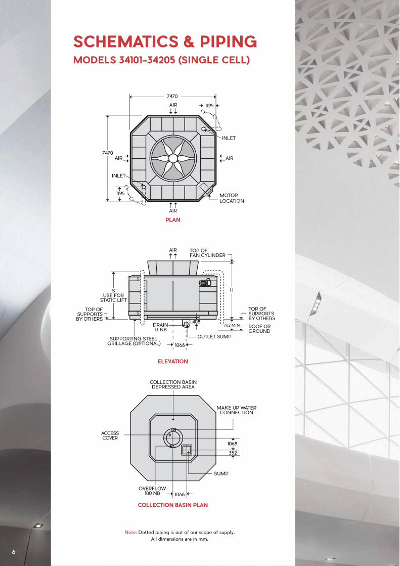
SCHEMATICS & PIPINGMODELS 34101-34205 (SINGLE CELL)
COLLECTION BASIN PLAN
PLAN
ELEVATION
Note: Dotted piping is out of our scope of supply.
All dimensions are in mm.
MOTOR LOCATION
7470
7470
1195
1195
INLET
INLET
AIRAIR
AIR
AIR
OVERFLOW100 NB
ACCESSCOVER
COLLECTION BASINDEPRESSED AREA
MAKE UP WATERCONNECTION
SUMP
352
1068
1068
6
TOP OFSUPPORTSBY OTHERS
TOP OFFAN CYLINDER
ROOF ORGROUND
OUTLET SUMP
1068
TOP OFSUPPORTSBY OTHERS
408DRAIN13 NB
762 MIN
SUSE FOR
STATIC LIFT
H
SUPPORTING STEEL GRILLAGE (OPTIONAL)
AIR
Note:
Dimensions shown are for preliminary layout only. Obtain current engineering drawings (or CAD files) from your Paharpur Sales
Engineer for final layout.
Make-up water connection may be 25 NB or 50 NB, depending upon tower heat load, water pressure and desired connections.
All table data is per cell.
All piping loads must be supported independent of tower.
All piping and supports are by others.
When inlet riser is located directly behind motor, maintain 600 mm gap between out of tower and in of riser pipe.
Outlet diameters shown are for maximum water flow. Smaller outlet diameters may be appropriate if design flow is less.
Outlet sump may be installed rotated 90O or 180O provided outlet piping will clear tower support.
* Nominal tons are based on 95°F hot water, 85°F cold water, 78°F wet bulb and 3 USGPM per ton.
Multi-cell models also available. Details available on request.
H S
TOWER MODEL
NOMINAL TONS*
FAN TYPE
FAN DIA.(INCH)
FAN RPM
MOTOR HP
GEARBOX SERIES
(TYPE CC2)
GEARBOX RATIO
DRIVESHAFT SERIES
DIMENSIONS
(MM)
34101 466 3874 2972 H-3-9 144 266 15 22.2 5.50:1 175 7115 23960
34102 516 3874 2972 H-3-9 144 266 20 22.2 5.50:1 175 7145 23990
34103 556 3874 2972 H-3-9 144 266 25 22.2 5.50:1 175 7165 24010
34104 591 3874 2972 H-3-9 144 320 30 22.2 4.56:1 175 7195 24025
34105 648 3874 2972 H-3-9 144 320 40 22.2 4.56:1 175 7260 24100
34106 696 3874 2972 H-3-9 144 428 50 22.2 3.45:1 175 7285 24125
34107 734 3874 2972 H-3-9 144 428 60 22.2 3.45:1 175 7410 24255
34201 699 4902 3988 H-3-9 144 266 25 22.2 5.50:1 175 8080 24925
34202 740 4902 3988 H-3-9 144 320 30 22.2 4.56:1 175 8110 24950
34203 809 4902 3988 H-3-9 144 320 40 22.2 4.56:1 175 8180 25020
34204 868 4902 3988 H-3-9 144 428 50 22.2 3.45:1 175 8205 25040
34205 919 4902 3988 H-3-9 144 428 60 22.2 3.45:1 175 8330 25170
APPROX. SHIPPING WT. (KG)
APPROX. OPERATING
WT. (KG)
7

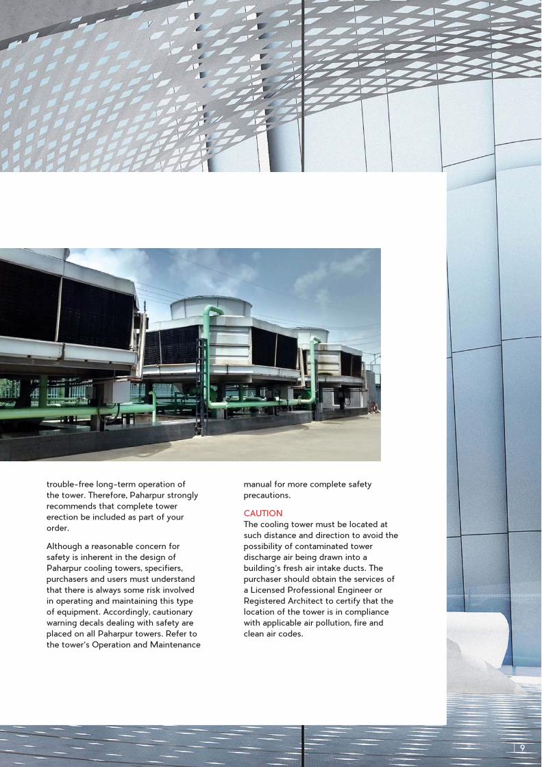
OXF-30K towers are factory-fabricated
and are designed to be assembled at
the jobsite. This allows the design
flexibility that results in the uniquely
pleasant OXF-30K configuration and
permits a wide variety of orientations.
Normally this assembly is included as
part of the cooling tower contract and is
performed by a team of workmen
supervised by an experienced Paharpur
erection foreman. Their knowledge and
expertise assure proper fit-up,
alignment, sealing and warrantability of
the various tower components, and
contributes significantly to the
OXF-30K ON-SITE ASSEMBLY
8
trouble-free long-term operation of
the tower. Therefore, Paharpur strongly
recommends that complete tower
erection be included as part of your
order.
Although a reasonable concern for
safety is inherent in the design of
Paharpur cooling towers, specifiers,
purchasers and users must understand
that there is always some risk involved
in operating and maintaining this type
of equipment. Accordingly, cautionary
warning decals dealing with safety are
placed on all Paharpur towers. Refer to
the tower’s Operation and Maintenance
manual for more complete safety
precautions.
CAUTION
The cooling tower must be located at
such distance and direction to avoid the
possibility of contaminated tower
discharge air being drawn into a
building’s fresh air intake ducts. The
purchaser should obtain the services of
a Licensed Professional Engineer or
Registered Architect to certify that the
location of the tower is in compliance
with applicable air pollution, fire and
clean air codes.
9
ENCLOSURES
Occasionally, cooling towers are located
inside architectural enclosures for
aesthetic reasons. Although Paharpur
cooling towers adapt well to enclosures,
the designer must realise the potential
impact of a poorly arranged enclosure
on the tower's performance and
operation. The designer must take care
to provide generous air inlet paths and
the minimum distance specified should
be observed.
NOISE LEVEL
Sound produced by a series OXF-30K
tower operating in an unobstructed
environment will meet all but the most
restrictive noise limitations and will
react favourably to natural attenuation.
Where the tower has been designed to
operate within an enclosure, the
enclosure itself will usually have a
dampening effect on sound. Sound also
declines with distance by about 5 dBA
each time the distance doubles. Where
noise at a critical point is likely to
exceed an acceptable limit, you have
several options listed in ascending order
of cost impact:
In many cases, noise concerns are
limited to night-time, when ambient
noise levels are lower. Such situations
are tackled by using two (2) speed
motors in either 1500/1000 or
1500/750 rpm configuration; and
operating the fans at reduced speed
instead of ‘cycling’ at full speed.
Typical sound reductions are 9 dBA at
two-third fan speed or 13 dBA at
halfspeed. This is a relatively
inexpensive solution and pays for
itself quickly in reduced energy costs.
Where noise is a concern at all times
(for example, near a hospital) the best
solution is to oversize the tower so it
can operate continuously at reduced
motor horse power.
Extreme cases may require inlet and
discharge sound attenuator sections;
however, the static pressure loss
imposed by attenuators may
necessitate an increase in tower size.
This is the least desirable approach
because of significant cost impact and
because of obstruction to normal
maintenance procedures.
OPERATIONAL AND ENVIRONMENTAL CONSIDERATIONS
10
APPROPRIATE OXF-30K APPLICATIONS
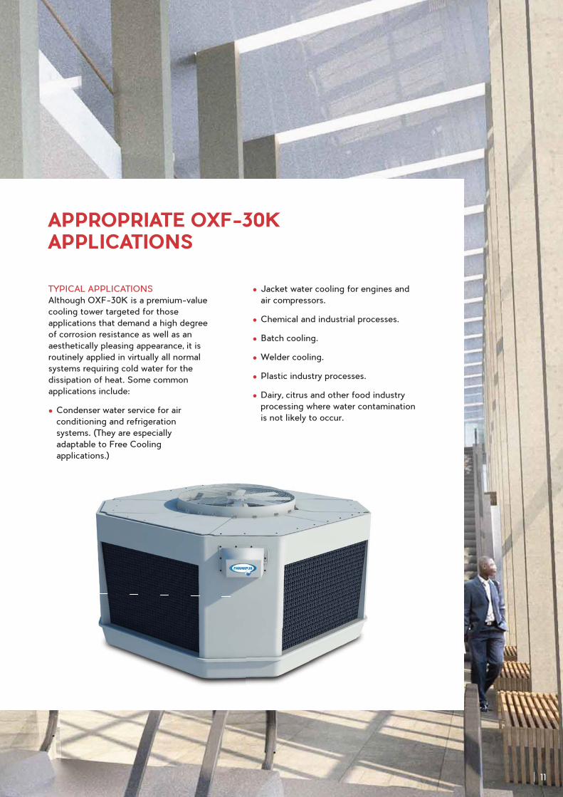
TYPICAL APPLICATIONS
Although OXF-30K is a premium-value
cooling tower targeted for those
applications that demand a high degree
of corrosion resistance as well as an
aesthetically pleasing appearance, it is
routinely applied in virtually all normal
systems requiring cold water for the
dissipation of heat. Some common
applications include:
Condenser water service for air
conditioning and refrigeration
systems. (They are especially
adaptable to Free Cooling
applications.)
Jacket water cooling for engines and
air compressors.
Chemical and industrial processes.
Batch cooling.
Welder cooling.
Plastic industry processes.
Dairy, citrus and other food industry
processing where water contamination
is not likely to occur.
11
BASE
Furnish and install a CTI Certified (as
per CTI STD-201) induced draught,
crossflow, field-erected, FRP cooling
tower of ........ cells, as shown on plans.
Tower shall be similar and equal in all
respects to Paharpur Series OXF-30K
Model ...............
PERFORMANCE
The tower shall be capable of cooling
........ CMH of water from ........ °C to ........
°C at a design wet-bulb temperature of
........ °C. The cooling tower manufacturer
shall guarantee the performance of the
tower as installed according to plans.
CONSTRUCTION
The cold water basin, structural columns,
hot water distribution basins, basin
covers, fan cylinder and access cover
shall be formed of inert fibre-reinforced
plastic (FRP). All hardware, including
the supporting grillage, shall be
fabricated of HDG steel. This shall
include the mechanical equipment
support structure, fan guards and all
bolts, nuts and fasteners used in the
construction of the tower.
MECHANICAL EQUIPMENT
Fan(s) shall be axial propeller type,
incorporating heavy duty blades of cast
aluminium alloy or FRP. Blade pitch
angle shall be individually adjustable.
Fan(s) shall be driven through a
right-angle, industrial-duty,
oil-lubricated, geared speed reducer.
Speed reducers employing pulleys and
belts shall not be acceptable.
Motor(s) shall be ........ HP, TEFC
weatherproof squirrel cage induction
type. Speed and electrical
characteristics shall be ........ RPM, single
winding, 3 phase, ........ hertz, ........ volts.
Motor shall be located outside the
humid interior of tower, within an alcove
in the tower’s corner structure.
The motor shall be connected to the
gear reducer by a tubular HDG steel
driveshaft equipped with neoprene
flexible coupling elements. A neoprene
oil gauge and drain line shall extend
from the gear reducer to the motor
enclosure and shall be equipped with an
easily visible oil sight glass. The
mechanical equipment for each cell shall
rest on a rigid HDG steel box-beam
assembly that resists misalignment
between the motor and the gear
reducer.
FILL, LOUVRES & DRIFT
ELIMINATORS
Fill shall be film-type, vacuum-formed
PVC, with louvres and drift eliminators
formed as part of the fill sheets. Fill
sheets shall be individually suspended
PAHARPUR SERIES OXF-30K COOLING TOWER SPECIFICATIONS
12
from steel structural tubing supported
by the tower columns and intermediate
panels and shall be elevated above the
floor of the cold water basin to facilitate
cleaning. Air inlet faces of the tower
shall be free of water splash-out and
guaranteed drift losses shall not exceed
0.005% of the design water flow rate.
HOT WATER DISTRIBUTION SYSTEM
The FRP hot water distribution basin
shall be equipped with metering
orifice-type polypropylene nozzles to
deliver incoming water by gravity to the
fill. Nozzles shall be easily removable
and replaceable. The hot water basin
shall be covered by removable FRP
covers that keep out sunlight to prevent
growth of algae and subsequent fouling,
and give a finished appearance to the
tower.
COLD WATER BASIN & ACCESSORIES
The FRP cold water basin shall be
sealed water-tight and shall include a
float-operated mechanical make-up
valve, an overflow connection and a
depressed FRP sump complete with
HDG steel debris screen. The top of the
basin to the base of the fill shall be
covered with heavy gauge HDG steel
screens to keep out airborne leaves and
debris. The cold water basin shall be
supported by a structural beam
assembly (Hot Dip Galvanized after
fabrication) or by a concrete slab.
SCOPE OF WORK
The cooling tower manufacturer shall be
responsible for the design, fabrication,
and delivery of materials to the project
site and for the erection of the tower
over supporting piers or dunnage
provided by others.
WARRANTY
The manufacturer shall warrant the
entire tower (including the motor)
against deficiency in performance and
failure due to defects in materials and
workmanship for a period of atleast
eighteen(18) months following shipment
to the site, or 12 months after the date
of startup, whichever is sooner.
OPTIONAL
Steel grillage or concrete slab support
(FRP basin jobs)
FRP cold water basin can be
substituted by concrete basin (by
purchaser). In this case, basin
accessories will also be deleted from
Paharpur’s scope.

www.paharpur.com
Domestic Sales Offices
Bangalore | Chennai | Hyderabad | Kolkata | Mumbai | New Delhi | Vadodara
Corporate Head Office
Paharpur House, 8/1/B, Diamond Harbour Road, Kolkata 700 027, India
Ph. : +91-33-4013 3000, Fax : +91-33-4013 3499, E-mail : [email protected]
Our sales representatives are located in several countries and Indian cities.Contact information shall be made available on request.
Paharpur Cooling Towers Ltd(ISO 9001:2008, ISO 14001:2004, OHSAS 18001:2007 Certified)
International Offices
USA | Switzerland | Belgium | Bahrain
OXF-30K-16-1.0/HL
Information contained in this document is correct as at the time of printing, and is subject to change without notice. For the latest information, please contact Paharpur.


![[Daniel Defoe, Thomas Keymer] Robinson Crusoe (Oxf(Bookos.org)](https://img.pdfslide.us/doc/110x75/577cd5fc1a28ab9e789bba2e/daniel-defoe-thomas-keymer-robinson-crusoe-oxfbookosorg.jpg)
![Rousseau, Political Economy [Oxf]](https://img.pdfslide.us/doc/110x75/55cf8cbc5503462b138f6b53/rousseau-political-economy-oxf.jpg)