Embed Size (px)
Citation preview
8/8/2019 Series LF009 Specification Sheet
http://slidepdf.com/reader/full/series-lf009-specification-sheet 1/4
LF009
ES-LF009
Series LF009Reduced Pressure Zone Assemblies
Sizes: 1 ⁄ 4" – 3" (8 – 80mm)Series LF009 Reduced Pressure Zone Assemblies are designed toprotect potable water supplies in accordance with national plumbingcodes and water authority requirements. This series can be used in avariety of installations, including the prevention of health hazard cross-connections in piping systems or for containment at the service lineentrance.The LF009 features Lead Free* construction to comply withLead Free* installation requirements.
This series features two in-line, independent check valves, capturedsprings and replaceable check seats with an intermediate relief valve.Its compact modular design facilitates easy maintenance and assem-bly access. Sizes 1 ⁄ 4" – 1" (8 – 25mm) shutoffs have tee handles.
Features• Single access cover and modular check construction
for ease of maintenance
• Top entry - all internals immediately accessible
• Captured springs for safe maintenance
• Internal relief valve for reduced installation clearances
• Replaceable seats for economical repair
• Lead Free* cast copper silicon alloy body construction for durability 1 ⁄ 4" – 2" (8 – 50mm)
• Fused epoxy coated cast iron body 21 ⁄ 2" and 3" (65 and 80mm)
• Ball valve test cocks — screwdriver slotted 1 ⁄ 4" – 2" (8 – 50mm)
• Large body passages provides low pressure drop
• Compact, space saving design
• No special tools required for servicing
Specifications A Reduced Pressure Zone Assembly shall be installed at each potentialhealth hazard location to prevent backflow due to backsiphonage and/ or backpressure. The assembly shall consist of an internal pressuredifferential relief valve located in a zone between two positive seatingcheck modules with captured springs and silicone seat discs. Seats and
seat discs shall be replaceable in both check modules and the reliefvalve. There shall be no threads or screws in the waterway exposed toline fluids. Service of all internal components shall be through a singleaccess cover secured with stainless steel bolts. Body and shutoffs shallbe constructed using Lead Free* cast copper silicon alloy materials.Lead Free* reduced pressure zone assembly shall comply with statecodes and standards, where applicable, requiring reduced lead content.
The assembly shall also include two resilient seated isolation valves,four resilient seated test cocks and an air gap drain fitting. The assem-bly shall meet the requirements of: USC; ASSE Std. 1013; AWWA Std.C511; CSA B64.4. Shall be a Watts Series LF009.
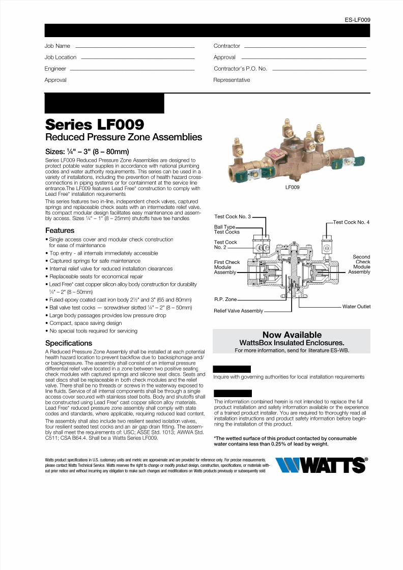
Test Cock No. 3Test Cock No. 4
R.P. Zone
Water Outle
Test CockNo. 2
First CheckModule
Assembly
SecondCheck
Module Assembly
Relief Valve Assembly
Ball TypeTest Cocks
For Health Hazard Applications
LEAD FREE*
Job Name ––––––––––––––––––––––––––––––––––––––––––– Contractor ––––––––––––––––––––––––––––––––––––––––––––
Job Location ––––––––––––––––––––––––––––––––––––––––– Approval –––––––––––––––––––––––––––––––––––––––––––––
Engineer ––––––––––––––––––––––––––––––––––––––––––––– Contractor’s P.O. No. ––––––––––––––––––––––––––––––––––
Approval ––––––––––––––––––––––––––––––––––––––––––––– Representative ––––––––––––––––––––––––––––––––––––––––
*The wetted surface of this product contacted by consumablewater contains less than 0.25% of lead by weight.
Now AvailableWattsBox Insulated Enclosures.
For more information, send for literature ES-WB.
NOTICE Inquire with governing authorities for local installation requirements
The information contained herein is not intended to replace the fullproduct installation and safety information available or the experienceof a trained product installer. You are required to thoroughly read allinstallation instructions and product safety information before begin-ning the installation of this product.
NOTICE
Watts product specifications in U.S. customary units and metric are approximate and are provided for reference only. For precise measurements,
please contact Watts Technical Service. Watts reserves the right to change or modify product design, construction, specifications, or materials with-
out prior notice and without incurring any obligation to make such changes and modifications on Watts products previously or subsequently sold.
8/8/2019 Series LF009 Specification Sheet
http://slidepdf.com/reader/full/series-lf009-specification-sheet 2/4
Available Models: 1 ⁄ 4" – 2" (8 – 50mm) Suffix:
QT – quarter-turn ball valves
S – strainer
LF – without shutoff valves
PC – internal polymer coating
Prefix:
U – union connections
Available Models: 21 ⁄ 2" – 3" (65 – 80mm)Suffix:
NRS – non-rising stem resilient seated gate valves
OSY – UL/FM outside stem and yoke resilient seated
gate valves
S-FDA – FDA epoxy coated strainer
QT-FDA – FDA epoxy coated quarter-turn ball valves
LF – without shutoff valves
Note: The installation of a drain line is recommended. When install-
ing a drain line, an air gap is necessary (see ES-AG).
Materials: 1 ⁄ 4" – 2" (8 – 50mm)
Lead Free* cast copper silicon alloy body construction, siliconerubber disc material in the first and second check plus the relief
valve. Replaceable polymer check seats for first and second
checks. Removable stainless steel relief valve seat. Stainless steel
cover bolts.
Standardly furnished with NPT body connections.
Model LF009QT furnished with quarter-turn, full port, resilient
seated, Lead Free* cast copper silicon alloy body ball valve
shutoffs.
Materials: 21 ⁄ 2" and 3" (65 – 80mm)• (FDA approved) Epoxy coated cast iron unibody with plastic seats
• Relief valve with stainless steel seat and trim
• Lead Free cast copper silicon alloy body ball valve test cocks
Pressure / TemperatureSizes 1 / 4" – 2" (8 – 50mm) Suitable for supply pressure up to
175psi (12 bar). Water temperature: 33°F – 180°F
(0.5° – 75°C).
Sizes 21 / 2" and 3" (65 and 80mm) are suitable for supply
pressures up to 175psi (12.1 bar) and water temperature at 110°F
(43°C) continuous, 140°F (60°C) intermittent.
Standards
USC ASSE No. 1013
AWWA C511
CSA B64.4
IAPMO File No. 1563.
Approvals ASSE, AWWA, CSA, IAPMO
Approved by the Foundation for Cross-Connection Control and
Hydraulic Research at the University of Southern California.
Approval models QT, PC, NRS, OSY.
UL Classified
21 ⁄ 2" and 3" (65 and 80mm) with OSY gate valves.3 / 4" - 2" (20-50mm) without shutoff valves (-LF) (except
LF009M3LF)
A
B
A
B
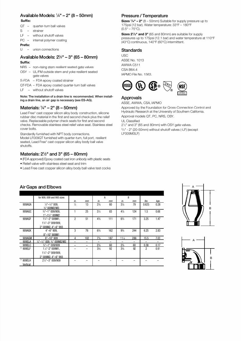
Air Gaps and Elbows
MODEL DRAIN OUTLET DIMENSIONS WEIGHT
for 909, 009 and 993 sizes A B
in. mm in. mm in. mm lbs. kgs.
909AGA 1 ⁄ 4"–1 ⁄ 2" 009, 1 ⁄ 2 13 23 ⁄ 8 60 31 ⁄ 8 79 0.625 0.283 ⁄ 4" 009M2/M3
909AGC 3 ⁄ 4"–1" 009/909, 1 25 31 ⁄ 4 83 47 ⁄ 8 124 1.5 0.68
1"–11 ⁄ 2" 009M2
909AGF 11 ⁄ 4"–2" 009M1,
11 ⁄ 4"–3" 009/909,
2" 009M2, 4"–6" 993
2 51 43 ⁄ 8 111 63 ⁄ 4 171 3.25 1.47
909AGK 4"–6" 909,
8"–10" 909M1
3 76 63 ⁄ 8 162 95 ⁄ 8 244 6.25 2.83
909AGM 8"–10" 909 4 102 73 ⁄ 8 187 111 ⁄ 4 286 15.5 7.03
909ELA 1 ⁄ 4"–1 ⁄ 2" 009, 3 ⁄ 4" 009M2/M3 – – – – – – – –
909ELC 3 ⁄ 4"–1" 009/909 – – 23 ⁄ 8 60 23 ⁄ 8 60 0.38 0.17
* 909ELF 11 ⁄ 4"-2" 009M1,
11 ⁄ 4"–2" 009/909,
2" 009M2, 4"–6" 993
– – 35 ⁄ 8 92 35 ⁄ 8 92 2 0.91
* 909ELH
Vertical
21 ⁄ 2"–3" 009/909 – – – – – – – –
8/8/2019 Series LF009 Specification Sheet
http://slidepdf.com/reader/full/series-lf009-specification-sheet 3/4
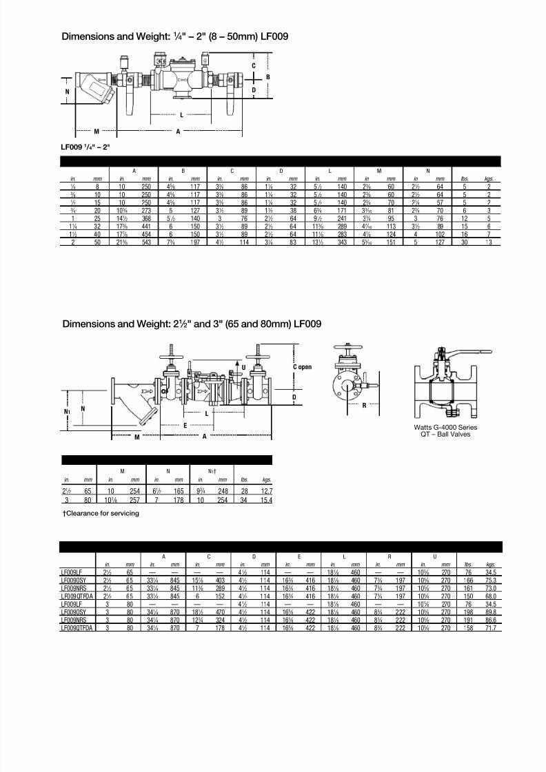
Dimensions and Weight: 21 ⁄ 2" and 3" (65 and 80mm) LF009
LF009 1 / 4" – 2"
SIZE (DN) DIMENSIONS (APPROX.) WEIGHT
A B C D L M N
in. mm in. mm in. mm in. mm in. mm in. mm in mm in mm lbs. kgs.1 ⁄ 4 8 10 250 45 ⁄ 8 117 33 ⁄ 8 86 11 ⁄ 4 32 51 ⁄ 2 140 23 ⁄ 8 60 21 ⁄ 2 64 5 23 ⁄ 8 10 10 250 45 ⁄ 8 117 33 ⁄ 8 86 11 ⁄ 4 32 51 ⁄ 2 140 23 ⁄ 8 60 21 ⁄ 2 64 5 21 ⁄ 2 15 10 250 45 ⁄ 8 117 33 ⁄ 8 86 11 ⁄ 4 32 51 ⁄ 2 140 23 ⁄ 4 70 21 ⁄ 4 57 5 23 ⁄ 4 20 103 ⁄ 4 273 5 127 31 ⁄ 2 89 11 ⁄ 2 38 63 ⁄ 4 171 33 ⁄ 16 81 23 ⁄ 4 70 6 3
1 25 141 ⁄ 2 368 51 ⁄ 2 140 3 76 21 ⁄ 2 64 91 ⁄ 2 241 33 ⁄ 4 95 3 76 12 5
11 ⁄ 4 32 173 ⁄ 8 441 6 150 31 ⁄ 2 89 21 ⁄ 2 64 113 ⁄ 8 289 47 ⁄ 16 113 31 ⁄ 2 89 15 6
11 ⁄ 2 40 177 ⁄ 8 454 6 150 31 ⁄ 2 89 21 ⁄ 2 64 111 ⁄ 8 283 47 ⁄ 8 124 4 102 16 7
2 50 213 ⁄ 8 543 73 ⁄ 4 197 41 ⁄ 2 114 31 ⁄ 4 83 131 ⁄ 2 343 55 ⁄ 16 151 5 127 30 13
Watts G-4000 SeriesQT – Ball ValvesM
N1 N
E
A
L
C open
D
U
R
STRAINER SIZE DIMENSIONS (APPROX.) WEIGHT
M N N1†
in. mm in. mm in. mm in. mm lbs. kgs.
21 ⁄ 2 65 10 254 61 ⁄ 2 165 93 ⁄ 4 248 28 12.7
3 80 101 ⁄ 8 257 7 178 10 254 34 15.4
†Clearance for servicing
Dimensions and Weight: 1 ⁄ 4" – 2" (8 – 50mm) LF009
N
M A
L
D
C
B
MODEL SIZE DN DIMENSIONS (APPROX.) WEIGHT
A C D E L R U
in. mm in. mm in. mm in. mm in. mm in. mm in. mm in. mm lbs. kgs.
LF009LF 21 ⁄ 2 65 — — — — 41 ⁄ 2 114 — — 181 ⁄ 8 460 — — 105 ⁄ 8 270 76 34.5
LF009OSY 21 ⁄ 2 65 331 ⁄ 4 845 157 ⁄ 8 403 41 ⁄ 2 114 163 ⁄ 8 416 181 ⁄ 8 460 73 ⁄ 4 197 105 ⁄ 8 270 166 75.3
LF009NRS 21 ⁄ 2 65 331 ⁄ 4 845 113 ⁄ 8 289 41 ⁄ 2 114 163 ⁄ 8 416 181 ⁄ 8 460 73 ⁄ 4 197 105 ⁄ 8 270 161 73.0
LF009QTFDA 21 ⁄ 2 65 331 ⁄ 4 845 6 152 41 ⁄ 2 114 163 ⁄ 8 416 181 ⁄ 8 460 73 ⁄ 4 197 105 ⁄ 8 270 150 68.0
LF009LF 3 80 — — — — 41 ⁄ 2 114 — — 181 ⁄ 8 460 — — 105 ⁄ 8 270 76 34.5
LF009OSY 3 80 341 ⁄ 4 870 181 ⁄ 2 470 41 ⁄ 2 114 165 ⁄ 8 422 181 ⁄ 8 460 83 ⁄ 4 222 105 ⁄ 8 270 198 89.8
LF009NRS 3 80 341 ⁄ 4 870 123 ⁄ 4 324 41 ⁄ 2 114 165 ⁄ 8 422 181 ⁄ 8 460 83 ⁄ 4 222 105 ⁄ 8 270 191 86.6
LF009QTFDA 3 80 341 ⁄ 4 870 7 178 41 ⁄ 2 114 165 ⁄ 8 422 181 ⁄ 8 460 83 ⁄ 4 222 105 ⁄ 8 270 158 71.7
8/8/2019 Series LF009 Specification Sheet
http://slidepdf.com/reader/full/series-lf009-specification-sheet 4/4
0 .25 .60 .75 1 1.17 gpm
0 .95 1.9 2.9 3.8 4.5 lpm
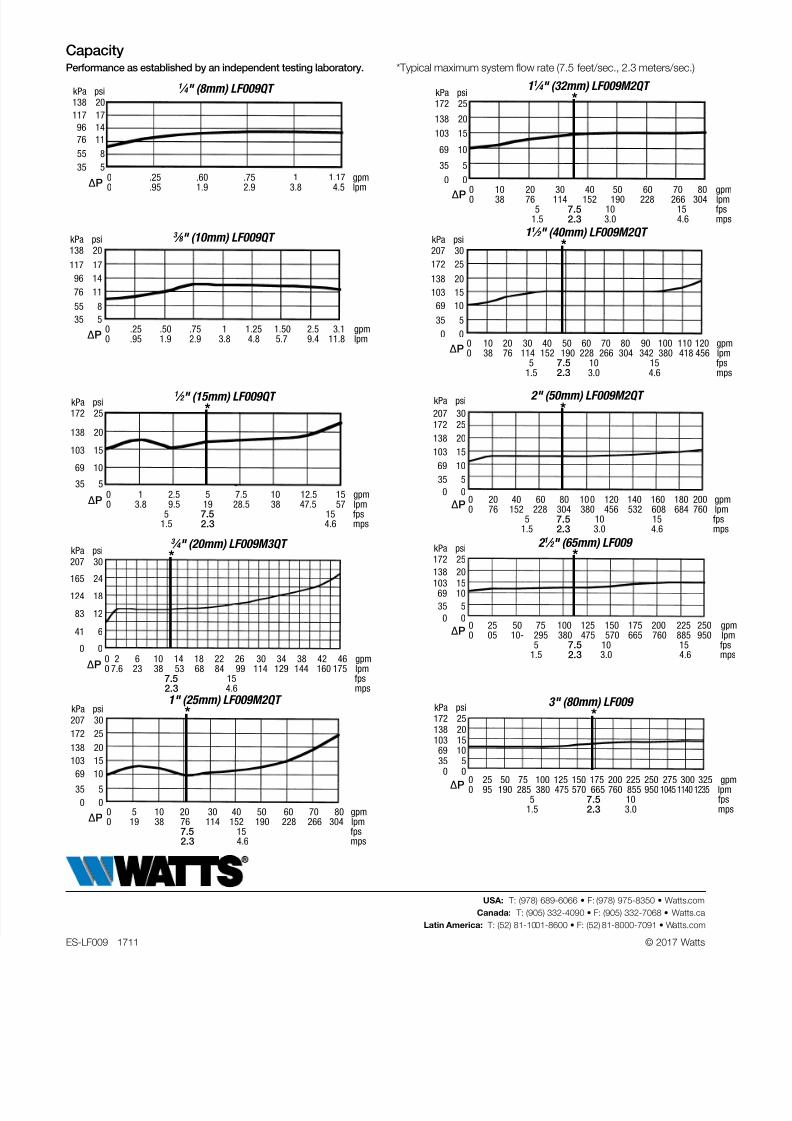
CapacityPerformance as established by an independent testing laboratory. *Typical maximum system flow rate (7.5 feet/sec., 2.3 meters/sec.)
1 ⁄ 4 " (8mm) LF009QT
3 ⁄ 8 " (10mm) LF009QT
1 ⁄ 2 " (15mm) LF009QT
kPa psi 138 20
117 17
96 14
76 11
55 8
35 5
kPa psi 138 20
117 17
96 14
76 11
55 8
35 50 .25 .50 .75 1 1.25 1.50 2.5 3.1 gpm0 .95 1.9 2.9 3.8 4.8 5.7 9.4 11.8 lpm
kPa psi
207 30
165 24
124 18
83 12
41 6
0 00 2 6 10 14 18 22 26 30 34 38 42 46 gpm0 7.6 23 38 53 68 84 99 114 129 144 160 175 lpm 7.5 15 fps 2.3 4.6 mps
kPa psi 207 30
172 25
138 20 103 15
69 10
35 5
0 00 5 10 20 30 40 50 60 70 80 gpm0 19 38 76 114 152 190 228 266 304 lpm 7.5 15 fps 2.3 4.6 mps
kPa psi 172 25
138 20
103 15
69 10
35 50 1 2.5 5 7.5 10 12.5 15 gpm0 3.8 9.5 19 28.5 38 47.5 57 lpm 5 7.5 15 fps 1.5 2.3 4.6 mps
11 ⁄ 4 " (32mm) LF009M2QT kPa psi 172 25
138 20
103 15
69 10
35 5
0 0
0 10 20 30 40 50 60 70 80 gpm0 38 76 114 152 190 228 266 304 lpm 5 7.5 10 15 fps 1.5 2.3 3.0 4.6 mp
kPa psi 207 30
172 25
138 20
103 15
69 10
35 5
0 00 10 20 30 40 50 60 70 80 90 100 110 120 gpm0 38 76 114 152 190 228 266 304 342 380 418 456 lpm 5 7.5 10 15 fps
1.5 2.3 3.0 4.6 mp
kPa psi
172 25 138 20 103 15 69 10
35 5
0 00 25 50 75 100 125 150 175 200 225 250 gp0 05 10- 295 380 475 570 665 760 885 950 lp 5 7.5 10 15 fp 1.5 2.3 3.0 4.6 m
kPa psi 172 25 138 20 103 15
69 10 35 5 0 0
0 25 50 75 100 125 150 175 200 225 250 275 300 325 gp0 95 190 285 380 475 570 665 760 855 950 1045 1140 1235 lp 5 7.5 10 fp 1.5 2.3 3.0 m
kPa psi
207 30172 25
138 20
103 15
69 10
35 5
0 00 20 40 60 80 100 120 140 160 180 200 gpm0 76 152 228 304 380 456 532 608 684 760 lpm 5 7.5 10 15 fps 1.5 2.3 3.0 4.6 mps
11 ⁄ 2 " (40mm) LF009M2QT
2" (50mm) LF009M2QT
2 1 ⁄ 2 " (65mm) LF009
3" (80mm) LF009
3 ⁄ 4 " (20mm) LF009M3QT
1" (25mm) LF009M2QT
*
*
*
*
*
*
*
*
∆P
∆P
∆P
∆P
∆P
∆P
∆P
∆P
∆P
∆P
ES-LF009 1711 © 2017 Watts
USA: T: (978) 689-6066 • F: (978) 975-8350 • Watts.com
Canada: T: (905) 332-4090 • F: (905) 332-7068 • Watts.ca
Latin America: T: (52) 81-1001-8600 • F: (52) 81-8000-7091 • Watts.com