Embed Size (px)
Citation preview
SERIES HP-APOWER TRANSMISSION SOLUTIONS
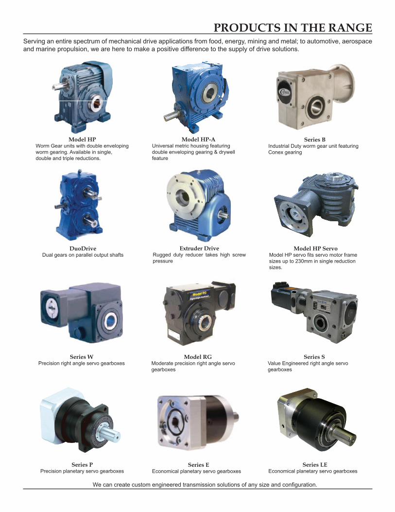
PRODUCTS IN THE RANGEServing an entire spectrum of mechanical drive applications from food, energy, mining and metal; to automotive, aerospace and marine propulsion, we are here to make a positive difference to the supply of drive solutions.
We can create custom engineered transmission solutions of any size and configuration.
Series LEEconomical planetary servo gearboxes
Model HP ServoModel HP servo fits servo motor frame sizes up to 230mm in single reduction sizes.
Series SValue Engineered right angle servo gearboxes
Model RG Moderate precision right angle servo gearboxes
Series WPrecision right angle servo gearboxes
Series BIndustrial Duty worm gear unit featuring Conex gearing
DuoDriveDual gears on parallel output shafts
Extruder DriveRugged duty reducer takes high screw pressure
Series PPrecision planetary servo gearboxes
Series EEconomical planetary servo gearboxes
Model HPWorm Gear units with double enveloping worm gearing. Available in single, double and triple reductions.
Model HP-AUniversal metric housing featuring double enveloping gearing & drywell feature
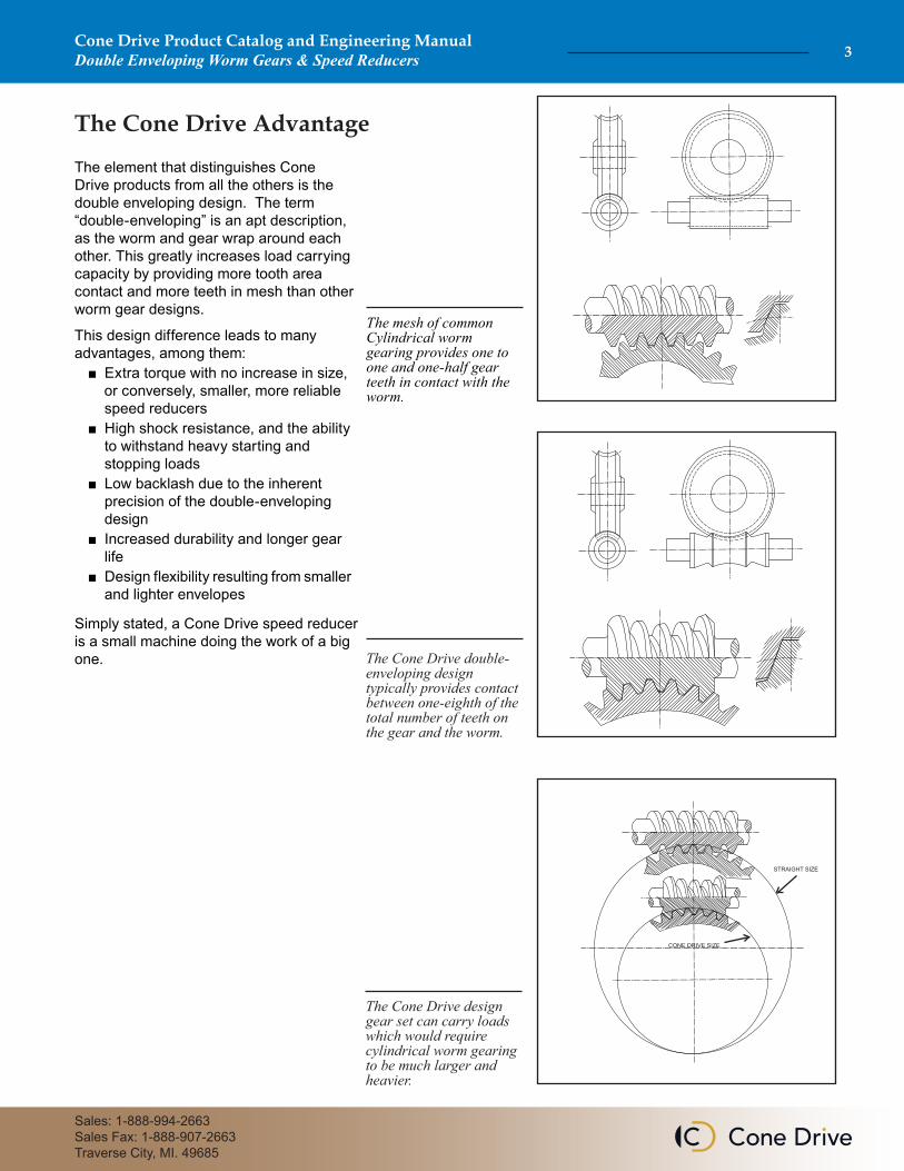
The mesh of common Cylindrical worm gearing provides one to one and one-half gear teeth in contact with the worm.
The Cone Drive double-enveloping design typically provides contact between one-eighth of the total number of teeth on the gear and the worm.
The Cone Drive design gear set can carry loads which would require cylindrical worm gearing to be much larger and heavier.
The element that distinguishes Cone Drive products from all the others is the double enveloping design. The term “double-enveloping” is an apt description, as the worm and gear wrap around each other. This greatly increases load carrying capacity by providing more tooth area contact and more teeth in mesh than other worm gear designs.
This design difference leads to many advantages, among them: ■ Extra torque with no increase in size, or conversely, smaller, more reliable speed reducers ■ High shock resistance, and the ability to withstand heavy starting and stopping loads ■ Low backlash due to the inherent precision of the double-enveloping design ■ Increased durability and longer gear life ■ Design flexibility resulting from smaller and lighter envelopes
Simply stated, a Cone Drive speed reducer is a small machine doing the work of a big one.
The Cone Drive Advantage
CONE DRIVE SIZE
STRAIGHT SIZE
Cone Drive Product Catalog and Engineering ManualDouble Enveloping Worm Gears & Speed Reducers 3
Sales: 1-888-994-2663Sales Fax: 1-888-907-2663Traverse City, MI. 49685
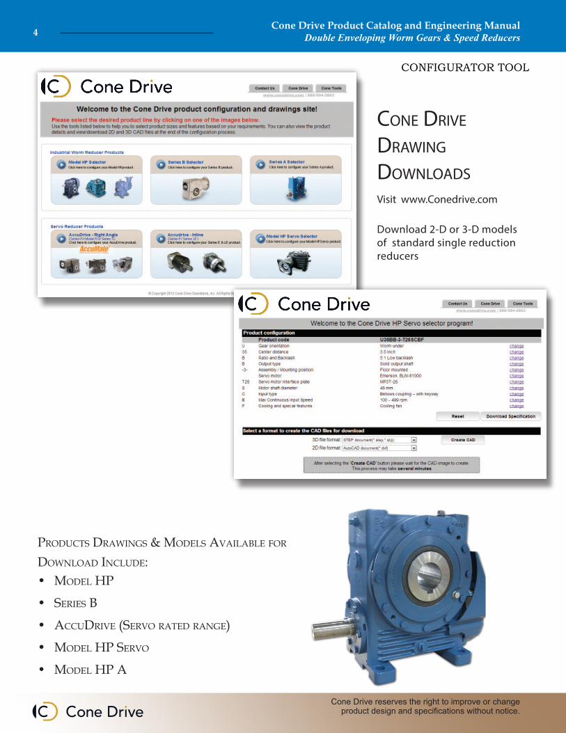
Cone Drive Drawing DownloaDs
Visit www.Conedrive.com
Download 2-D or 3-D models of standard single reduction reducers
CONFIGURATOR TOOL
Products drawings & Models available for download include:• Model HP
• series b
• accudrive (servo rated range)
• Model HP servo
• Model HP a
Cone Drive Product Catalog and Engineering ManualDouble Enveloping Worm Gears & Speed Reducers4
Cone Drive reserves the right to improve or change product design and specifications without notice.
Cone Drive Product Catalog and Engineering ManualDouble Enveloping Worm Gears & Speed Reducers 5
Sales: 1-888-994-2663Sales Fax: 1-888-907-2663Traverse City, MI. 49685
Table of contentsGeneral Description - - - - - - - - - - - - - - - - - - - - - - - - - - - - - - - - - - - - - - - - 6
Selection Procedure - - - - - - - - - - - - - - - - - - - - - - - - - - - - - - - - - - - - - - - - - 8
Explanation and use of Ratings and Service Factors - - - - - - - - - - - - - - - - - 9
Unit Designations - - - - - - - - - - - - - - - - - - - - - - - - - - - - - - - - - - - - - - - - - 10
Gear Unit Features - - - - - - - - - - - - - - - - - - - - - - - - - - - - - - - - - - - - - - - - 11
Mounting Positions and Shaft Handlings - - - - - - - - - - - - - - - - - - - - - 12 - 13
Exact Ratios - - - - - - - - - - - - - - - - - - - - - - - - - - - - - - - - - - - - - - - - - - - - - - 14
Output Shaft Options and Additional Features - - - - - - - - - - - - - - - - - - - 15
Motor Adaptors and Motor Details - - - - - - - - - - - - - - - - - - - - - - - - - - - - 16
Overhung and Axial Loads on Shafts - - - - - - - - - - - - - - - - - - - - - - - - 17 - 18
Reducer Backlash Levels - - - - - - - - - - - - - - - - - - - - - - - - - - - - - - - - - - - - 19
Competitor Interchange - - - - - - - - - - - - - - - - - - - - - - - - - - - - - - - - - - - - - 20
Single Reduction - A100 drawing and rating tables - - - - - - - - - - - - - - 22 - 23
Single Reduction - A125 drawing and rating tables - - - - - - - - - - - - - - 24 - 25
Single Reduction - A160 drawing and rating tables - - - - - - - - - - - - - - 26 - 27
Single Reduction - A200 drawing and rating tables - - - - - - - - - - - - - - 28 - 29
Fan Cooling Dimensions - - - - - - - - - - - - - - - - - - - - - - - - - - - - - - - - - - - - 30
Open Worm Gear Sets - - - - - - - - - - - - - - - - - - - - - - - - - - - - - - - - - - - - - - 31
Shipping Specifications - - - - - - - - - - - - - - - - - - - - - - - - - - - - - - - - - - - - - 32
Moments of Inertia - - - - - - - - - - - - - - - - - - - - - - - - - - - - - - - - - - - - - - - - 33
INSTALLATION AND MAINTENANCE
Installation and Maintenance - - - - - - - - - - - - - - - - - - - - - - - - - - - - - - 35 - 38
Lubrication - - - - - - - - - - - - - - - - - - - - - - - - - - - - - - - - - - - - - - - - - - - - - - 39
Oil Capacities - - - - - - - - - - - - - - - - - - - - - - - - - - - - - - - - - - - - - - - - - - - - 40
Customer Shaft Details - - - - - - - - - - - - - - - - - - - - - - - - - - - - - - - - - - - - - 41
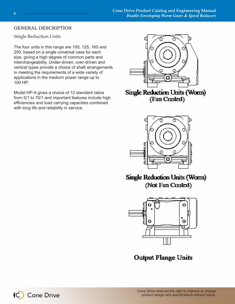
Single Reduction Units
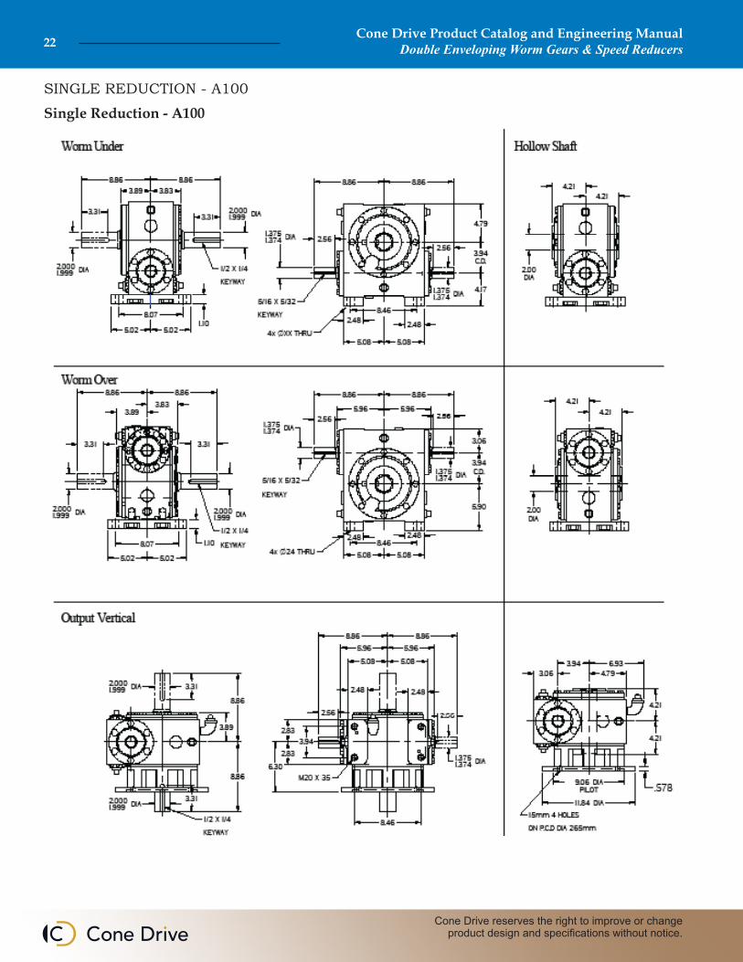
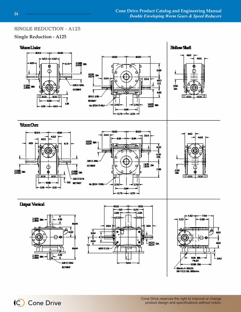
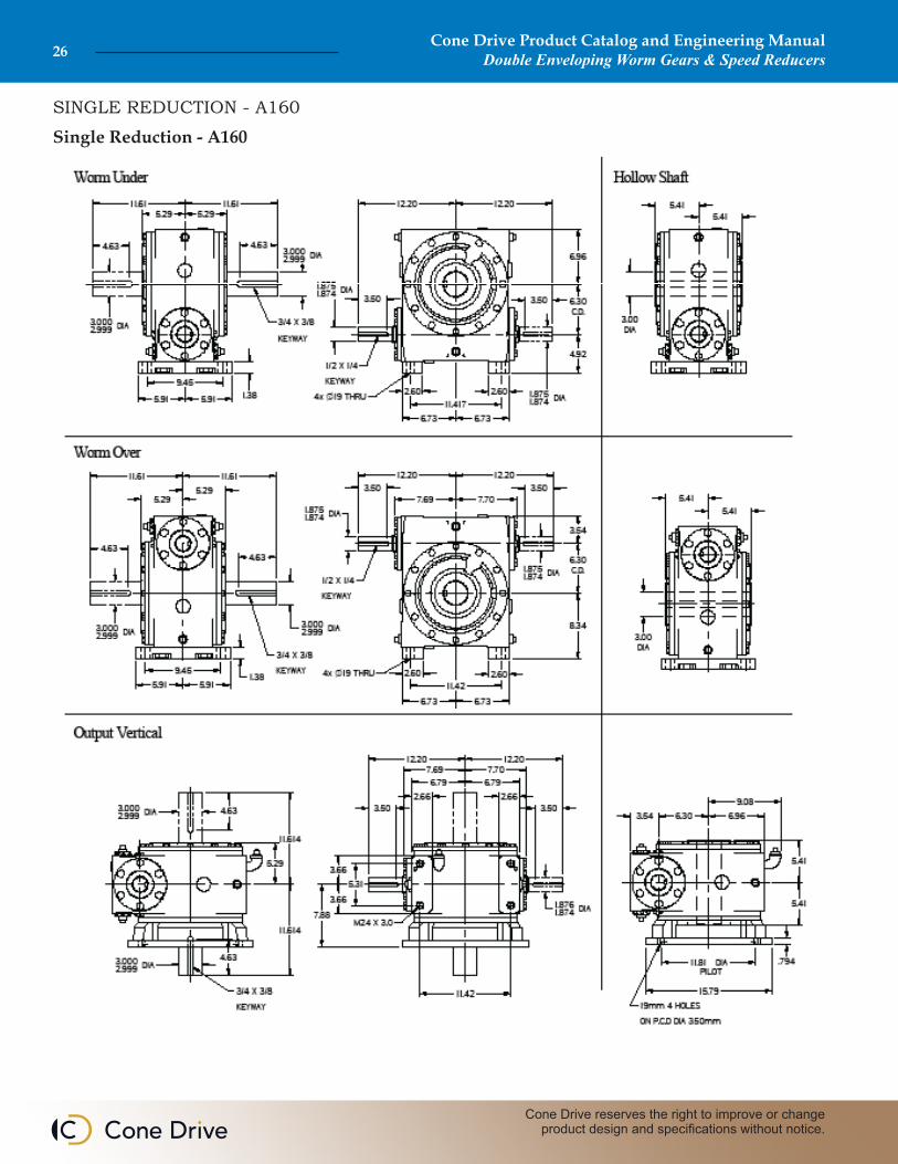
The four units in this range are 100, 125, 160 and 200, based on a single universal case for each size, giving a high degree of common parts and interchangeability. Under-driven, over-driven and vertical types provide a choice of shaft arrangements in meeting the requirements of a wide variety of applications in the medium power range up to 100 HP.
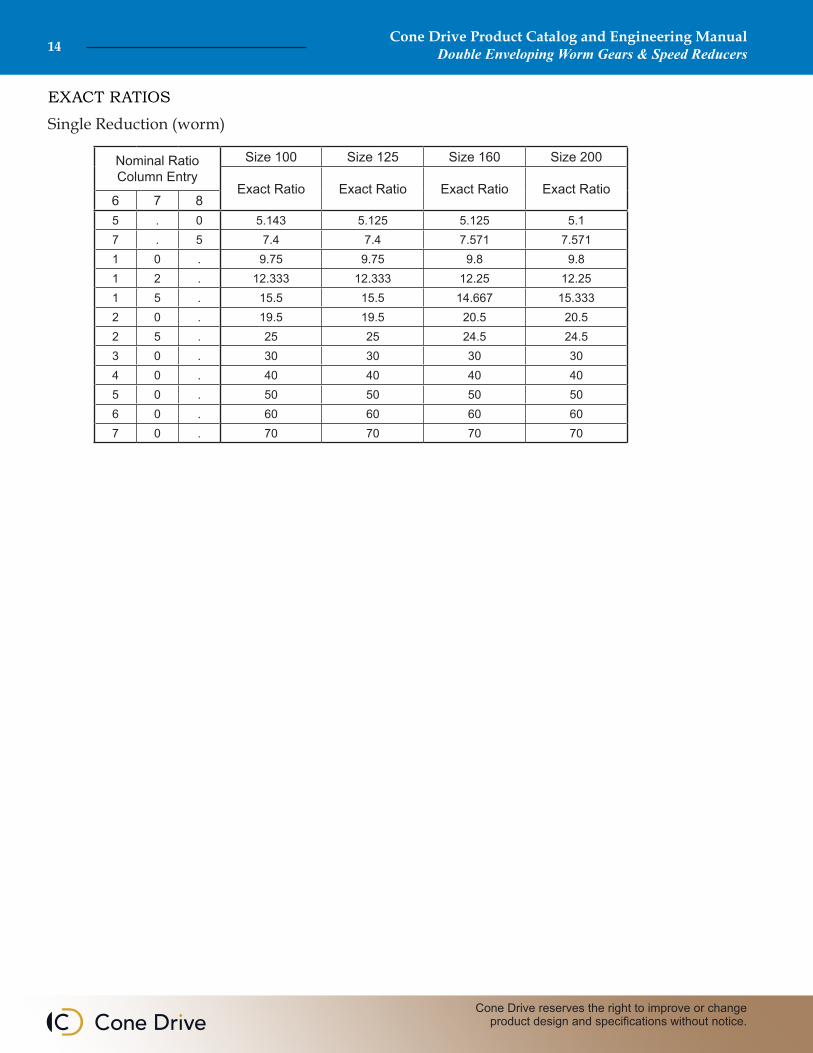
Model HP-A gives a choice of 12 standard ratios from 5/1 to 70/1 and important features include high efficiencies and load carrying capacities combined with long life and reliability in service.
Cone Drive Product Catalog and Engineering ManualDouble Enveloping Worm Gears & Speed Reducers6
Cone Drive reserves the right to improve or change product design and specifications without notice.
GENERAL DESCRIPTION
MAKING A SELECTION FOR YOUR APPLICATION
We look forward to serving you. Please phone us at 1-888-994-2663 for help specifying gear ratio, speed, duty cycle, and backlash. Or tell us about your application by faxing us the information below to 1-888-907-2663. Our dedicated teams are waiting for your call.
1. Application: • General type of application or machine. • Specific consideration; eg. positioning accuracy, shock loading, or self-locking. 2. Duty cycle: • Continuous or intermittent If continuous: • Hours per week If intermittent: • How many starts and stops per hour. • Average “on” time per hour. 3. Ratio and operating speed: • Variable or continuous speed input. • Preferred input speed. • Desired output speed. 4. Loading: • Horsepower or torque available or required for starting, running, and stopping. • General type of driving motor; eg. AC motor, servo motor, or hydraulic motor. • Special load classification; eg. shock loading, reversing, potential for emergency stops. • Unusually high inertia loading at the input or output shaft. • Overhung and/or thrust loading on shafts.
5. Environmental: • Any unusual environmental conditions such as high or low temperature, grit or other contaminants, or wet or spray exposure. 6. Configuration: • With or without a Cone Drive supplied drive motor. • Flange mounting provisions for the drive motor. • Solid or hollow output shaft. • Special modifications, dimensions, or features desired.
If Cone Drive is to provide the motor, please provide the following information: 1. Horsepower (HP) 2. RPM 3. Frame Size 4. Phase 5. Cycle (Hertz) 6. Voltage 7. Enclosure 8. Type 9. Design 10. Duty 11. Percent slip 12. Brake rating 13. Conduit box location when exact location is required (see view)
If customer is to furnish and mount the motor, please provide the following information so that the correct motor adaptor and coupling will be provided. 1. Horsepower (HP) 2. Frame size 3. Speed 4. Motor pilot diameter 5. Motor shaft dimensions 6. Brake rating (when units or motors are to be equipped with brakes having a torque rating that exceeds the unit or motor rating, the brake rating must be used to select unit size. 7. Complete coupling information (if alternate coupling is required and is not being furnished by Cone Drive)
Cone Drive Product Catalog and Engineering ManualDouble Enveloping Worm Gears & Speed Reducers 7
Sales: 1-888-994-2663Sales Fax: 1-888-907-2663Traverse City, MI. 49685
SELECTION PROCEDURE
The Procedure for Determining Speed Reducer Load Capacity is as Follows:
1. Determine the proper service factor by matching your duty requirements with the “Service Factor” chart in this section.
2. Determine the actual input horsepower required to drive the reducer. In case of operating worm speed under 100 RPM. use only output torque ratings. Multiply this horsepower or torque value by the appropriate service factor rather than adjust the ratings in the Catalog. This will give you the adjusted horsepower or torque required.
3. Find the ratio by dividing the speed of the input shaft by the speed of the output shaft.
4. Referring to the ratings (See pages 23 - 29) section, select a unit, at the given worm RPM and ratio, having a corresponding mechanical rating (or one slightly in excess) to the adjusted horsepower or torque.
5. Check the actual input horsepower to be transmitted (horsepower before applying service factor) against the thermal rating listed in the same table as in 4 above. The thermal rating defines the maximum horsepower which can be transmitted continuously (30 minutes or longer). This is based on an oil sump temperature rise of 100°F above ambient, and must not exceed 200°F. If the thermal rating is a lower value than the mechanical rating, choose the unit on the basis of the thermal rating. Exceptions to this rule are applications, where operation is intermittent and does not permit thermal build-up. For applications involving multiple cycles the average horsepower required should be compared with the thermal rating of the reducer. Where water-cooled units are used, thermal ratings can be obtained from our Traverse City, Michigan office; where fan cooled units are used, use the fan cooled thermal ratings shown on the fan cooled pages in the Traditional Products Section.
6. If either input or output shaft is connected to driver or driven mechanism other than by direct shaft coupling, calculate overhung load requirements (Chain Pull) by dividing the torque demand by the pitch radius of the sprocket, sheave, spur or helical gear used. Multiply by the following factor: As modified by the applicable service factor, this load may not exceed the overhung load rating listed under Chain
Mg = gear ratio Ng Nwn = rotational speed of worm (rpm)P = power input to worm (Horsepower)Tw = input torque (inch pounds)Tg = output torque (inch pounds)
η = efficiency (percent)
Formula 1: P = Twn 63,000Formula 2: Tw = P • 63,000 n
Formula 3: Tg = Tw • mg • ηDefinitions
Horsepower, Speed and Torque Relationship
Pull in the HP. and Torque Ratings Tables. The Chain Pull figures are based on the center of the load being no further from the center line of the reducer than one-half the keyway length on the output shaft extension. When Chain Pull approaches full rated capacity as listed, use heat- treated foundation bolts (150,000 PSI tensile strength).
7. Cone Drive’s Application Engineering Department is available to assist you with selection of the reducer for your application. Computer programs and technical personnel are available to discuss your application. We invite you to forward all pertinent data to Cone Drive’s Traverse City, Michigan office or your local representative for our full review and selection assistance.
Type of Drive Overhung Load Factor
Chain Sprocket 1.00Spur or helical gearing 1.25“V” belt sheave 1.50Flat belt sheave 2.50
Cone Drive Product Catalog and Engineering ManualDouble Enveloping Worm Gears & Speed Reducers8
Cone Drive reserves the right to improve or change product design and specifications without notice.
SERVICE FACTORS (DUTY CYCLE)
Service Factors
Cone Drive Worm GearsWork in Any EnvironmentCone Drive double-enveloping worm gear reducers are operating in extreme environments all over the world. Here are more examples:• Food Processing and Chemical Mixing
The reducer is designed to withstand corrosion and protect the mixture from contamination.
• Coal Mining Feeder breaker drives are built to survive the dust, dirt, grim and shock loads, and do it all in a severely limited space.
• Marine Applications Naval ship capstans and winches driven by Cone Drives shed the effects of salt water spray.
• Taconite and Phosphate Handling Cone Drive has solved the problem of fine dust working its way into gearboxes, which can contaminate lubricants and ruin gear sets.
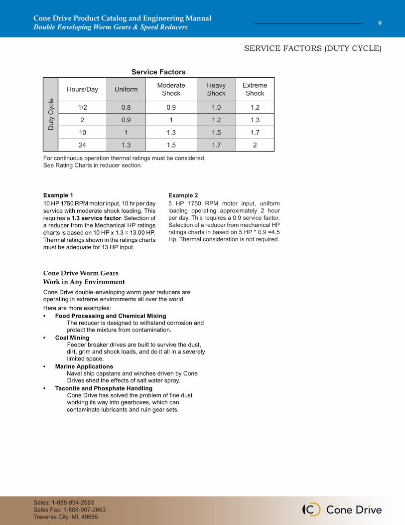
Example 110 HP 1750 RPM motor input, 10 hr per day service with moderate shock loading. This requires a 1.3 service factor. Selection of a reducer from the Mechanical HP ratings charts is based on 10 HP x 1.3 = 13.00 HP. Thermal ratings shown in the ratings charts must be adequate for 13 HP input.
For continuous operation thermal ratings must be considered. See Rating Charts in reducer section.
Example 25 HP 1750 RPM motor input, uniform loading operating approximately 2 hour per day. This requires a 0.9 service factor. Selection of a reducer from mechanical HP ratings charts in based on 5 HP * 0.9 =4.5 Hp. Thermal consideration is not required.
Dut
y C
ycle
Hours/Day Uniform Moderate Shock
Heavy Shock
Extreme Shock
1/2 0.8 0.9 1.0 1.2
2 0.9 1 1.2 1.3
10 1 1.3 1.5 1.7
24 1.3 1.5 1.7 2
Cone Drive Product Catalog and Engineering ManualDouble Enveloping Worm Gears & Speed Reducers 9
Sales: 1-888-994-2663Sales Fax: 1-888-907-2663Traverse City, MI. 49685
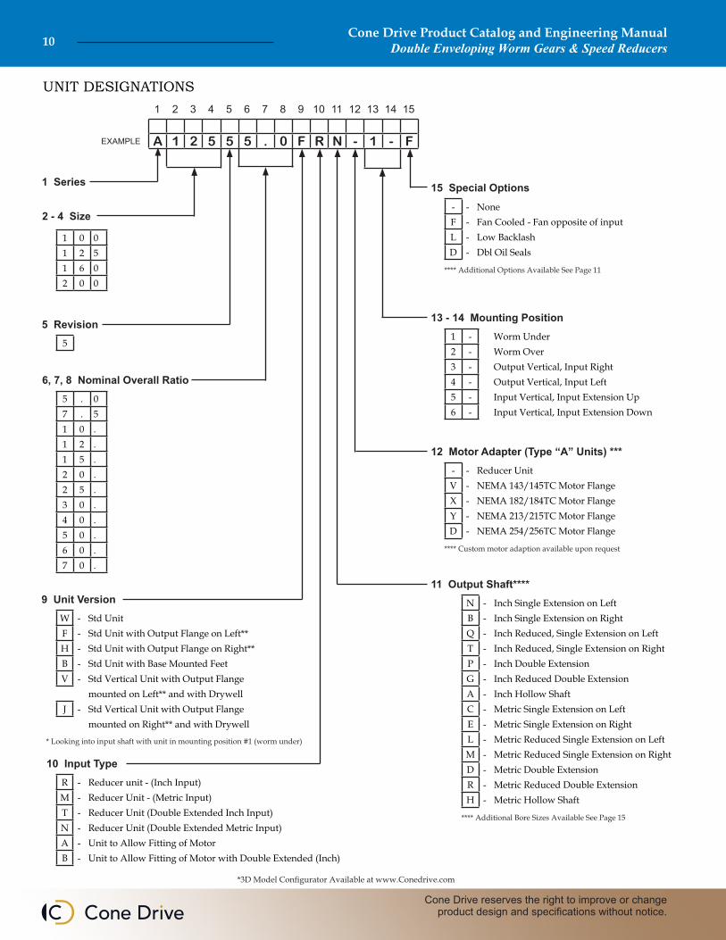
*3D Model Configurator Available at www.Conedrive.com
* Looking into input shaft with unit in mounting position #1 (worm under)
2 - 4 Size
1 Series
9 Unit Version
6, 7, 8 Nominal Overall Ratio
5 Revision
W - Std UnitF - Std Unit with Output Flange on Left**H - Std Unit with Output Flange on Right**B - Std Unit with Base Mounted FeetV - Std Vertical Unit with Output Flange
mounted on Left** and with DrywellJ - Std Vertical Unit with Output Flange
mounted on Right** and with Drywell
R - Reducer unit - (Inch Input)M - Reducer Unit - (Metric Input)T - Reducer Unit (Double Extended Inch Input)N - Reducer Unit (Double Extended Metric Input)A - Unit to Allow Fitting of MotorB - Unit to Allow Fitting of Motor with Double Extended (Inch)
1 0 01 2 51 6 02 0 0
5 . 07 . 51 0 .1 2 .1 5 .2 0 .2 5 .3 0 .4 0 .5 0 .6 0 .7 0 .
5
10 Input Type
A 1 2 5 5 5 . 0 F R N - 1 - F
1 2 3 4 5 6 7 8 9 10 11 12 13 14 15
EXAMPLE
**** Custom motor adaption available upon request
**** Additional Bore Sizes Available See Page 15
N - Inch Single Extension on LeftB - Inch Single Extension on RightQ - Inch Reduced, Single Extension on LeftT - Inch Reduced, Single Extension on RightP - Inch Double ExtensionG - Inch Reduced Double ExtensionA - Inch Hollow ShaftC - Metric Single Extension on LeftE - Metric Single Extension on RightL - Metric Reduced Single Extension on LeftM - Metric Reduced Single Extension on RightD - Metric Double ExtensionR - Metric Reduced Double ExtensionH - Metric Hollow Shaft
15 Special Options
12 Motor Adapter (Type “A” Units) ***
11 Output Shaft****
13 - 14 Mounting Position1 - Worm Under2 - Worm Over3 - Output Vertical, Input Right4 - Output Vertical, Input Left5 - Input Vertical, Input Extension Up6 - Input Vertical, Input Extension Down
- - NoneF - Fan Cooled - Fan opposite of inputL - Low BacklashD - Dbl Oil Seals
- - Reducer UnitV - NEMA 143/145TC Motor FlangeX - NEMA 182/184TC Motor FlangeY - NEMA 213/215TC Motor FlangeD - NEMA 254/256TC Motor Flange
**** Additional Options Available See Page 11
Cone Drive Product Catalog and Engineering ManualDouble Enveloping Worm Gears & Speed Reducers10
Cone Drive reserves the right to improve or change product design and specifications without notice.
UNIT DESIGNATIONS
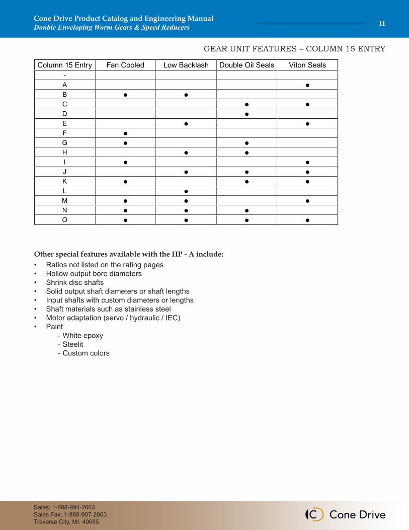
GEAR UNIT FEATURES – COLUMN 15 ENTRY
Column 15 Entry Fan Cooled Low Backlash Double Oil Seals Viton Seals-A ●B ● ●C ● ●D ●E ● ●F ●G ● ●H ● ●I ● ●J ● ● ●K ● ● ●L ●M ● ● ●N ● ● ●O ● ● ● ●
Cone Drive Product Catalog and Engineering ManualDouble Enveloping Worm Gears & Speed Reducers 11
Sales: 1-888-994-2663Sales Fax: 1-888-907-2663Traverse City, MI. 49685
Other special features available with the HP - A include:• Ratios not listed on the rating pages• Hollow output bore diameters• Shrink disc shafts• Solid output shaft diameters or shaft lengths• Input shafts with custom diameters or lengths• Shaft materials such as stainless steel• Motor adaptation (servo / hydraulic / IEC)• Paint - White epoxy - Steelit - Custom colors
Cone Drive Product Catalog and Engineering ManualDouble Enveloping Worm Gears & Speed Reducers12
Cone Drive reserves the right to improve or change product design and specifications without notice.
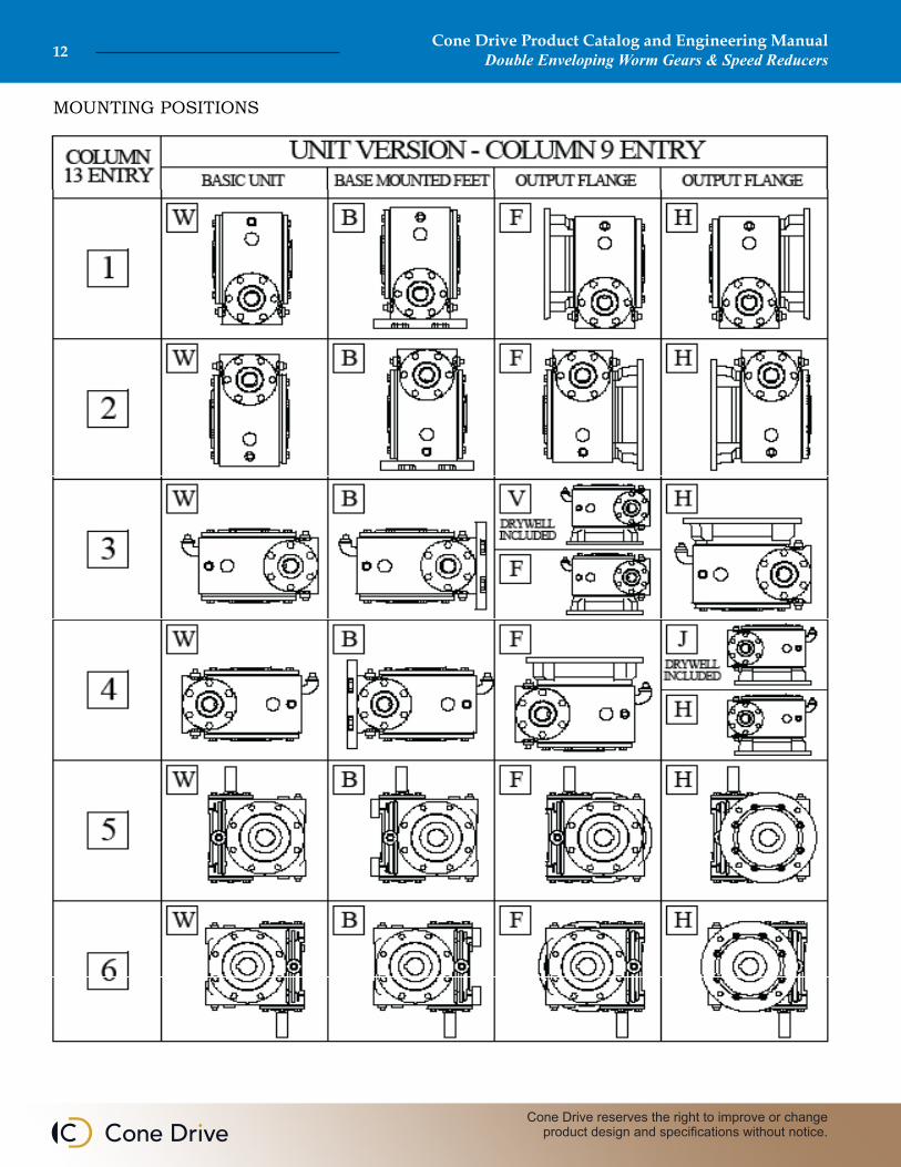
MOUNTING POSITIONS
Cone Drive Product Catalog and Engineering ManualDouble Enveloping Worm Gears & Speed Reducers 13
Sales: 1-888-994-2663Sales Fax: 1-888-907-2663Traverse City, MI. 49685
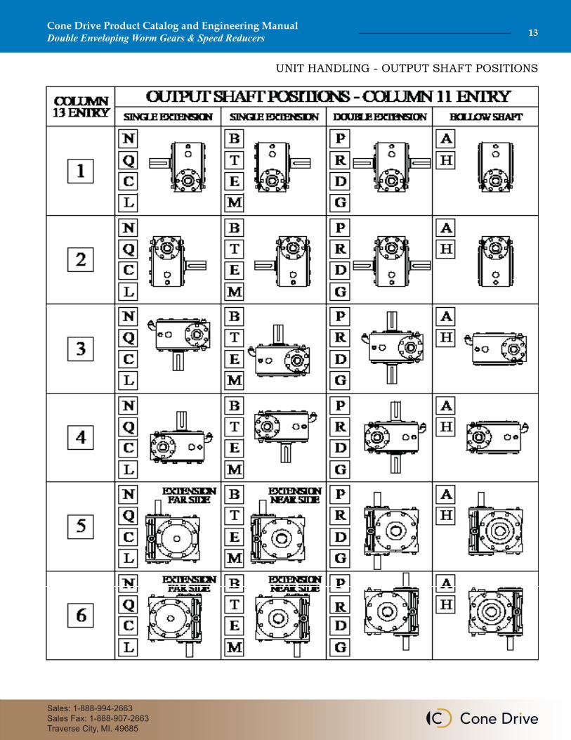
UNIT HANDLING - OUTPUT SHAFT POSITIONS
Cone Drive Product Catalog and Engineering ManualDouble Enveloping Worm Gears & Speed Reducers14
Cone Drive reserves the right to improve or change product design and specifications without notice.
Nominal RatioColumn Entry
Size 100 Size 125 Size 160 Size 200
Exact Ratio Exact Ratio Exact Ratio Exact Ratio6 7 85 . 0 5.143 5.125 5.125 5.17 . 5 7.4 7.4 7.571 7.5711 0 . 9.75 9.75 9.8 9.81 2 . 12.333 12.333 12.25 12.251 5 . 15.5 15.5 14.667 15.3332 0 . 19.5 19.5 20.5 20.52 5 . 25 25 24.5 24.53 0 . 30 30 30 304 0 . 40 40 40 405 0 . 50 50 50 506 0 . 60 60 60 607 0 . 70 70 70 70
Single Reduction (worm)EXACT RATIOS
Cone Drive Product Catalog and Engineering ManualDouble Enveloping Worm Gears & Speed Reducers 15
Sales: 1-888-994-2663Sales Fax: 1-888-907-2663Traverse City, MI. 49685
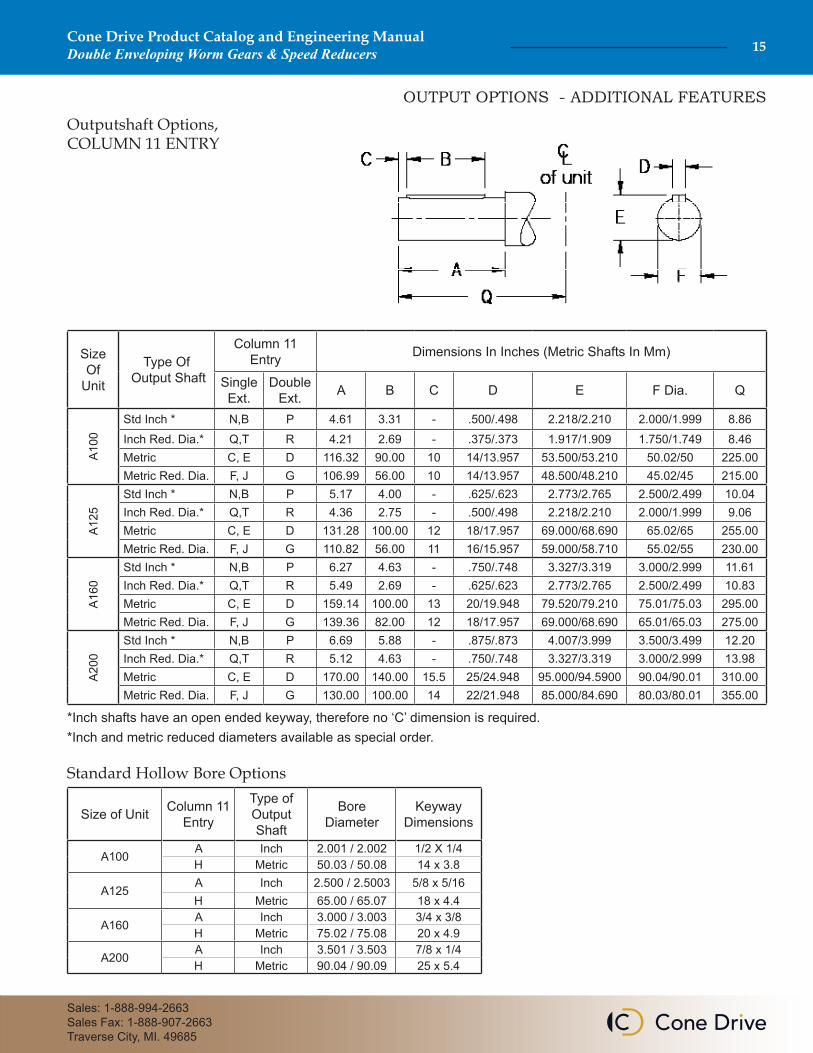
Standard Hollow Bore Options
OUTPUT OPTIONS - ADDITIONAL FEATURES
Outputshaft Options,COLUMN 11 ENTRY
Size Of
Unit
Type Of Output Shaft
Column 11 Entry Dimensions In Inches (Metric Shafts In Mm)
Single Ext.
Double Ext. A B C D E F Dia. Q
A100
Std Inch * N,B P 4.61 3.31 - .500/.498 2.218/2.210 2.000/1.999 8.86Inch Red. Dia.* Q,T R 4.21 2.69 - .375/.373 1.917/1.909 1.750/1.749 8.46Metric C, E D 116.32 90.00 10 14/13.957 53.500/53.210 50.02/50 225.00Metric Red. Dia. F, J G 106.99 56.00 10 14/13.957 48.500/48.210 45.02/45 215.00
A125
Std Inch * N,B P 5.17 4.00 - .625/.623 2.773/2.765 2.500/2.499 10.04Inch Red. Dia.* Q,T R 4.36 2.75 - .500/.498 2.218/2.210 2.000/1.999 9.06Metric C, E D 131.28 100.00 12 18/17.957 69.000/68.690 65.02/65 255.00Metric Red. Dia. F, J G 110.82 56.00 11 16/15.957 59.000/58.710 55.02/55 230.00
A160
Std Inch * N,B P 6.27 4.63 - .750/.748 3.327/3.319 3.000/2.999 11.61Inch Red. Dia.* Q,T R 5.49 2.69 - .625/.623 2.773/2.765 2.500/2.499 10.83Metric C, E D 159.14 100.00 13 20/19.948 79.520/79.210 75.01/75.03 295.00Metric Red. Dia. F, J G 139.36 82.00 12 18/17.957 69.000/68.690 65.01/65.03 275.00
A200
Std Inch * N,B P 6.69 5.88 - .875/.873 4.007/3.999 3.500/3.499 12.20Inch Red. Dia.* Q,T R 5.12 4.63 - .750/.748 3.327/3.319 3.000/2.999 13.98Metric C, E D 170.00 140.00 15.5 25/24.948 95.000/94.5900 90.04/90.01 310.00Metric Red. Dia. F, J G 130.00 100.00 14 22/21.948 85.000/84.690 80.03/80.01 355.00
*Inch shafts have an open ended keyway, therefore no ‘C’ dimension is required.*Inch and metric reduced diameters available as special order.
Size of Unit Column 11 Entry
Type of Output Shaft
Bore Diameter
Keyway Dimensions
A100 A Inch 2.001 / 2.002 1/2 X 1/4H Metric 50.03 / 50.08 14 x 3.8
A125 A Inch 2.500 / 2.5003 5/8 x 5/16H Metric 65.00 / 65.07 18 x 4.4
A160 A Inch 3.000 / 3.003 3/4 x 3/8H Metric 75.02 / 75.08 20 x 4.9
A200 A Inch 3.501 / 3.503 7/8 x 1/4H Metric 90.04 / 90.09 25 x 5.4
Cone Drive Product Catalog and Engineering ManualDouble Enveloping Worm Gears & Speed Reducers16
Cone Drive reserves the right to improve or change product design and specifications without notice.
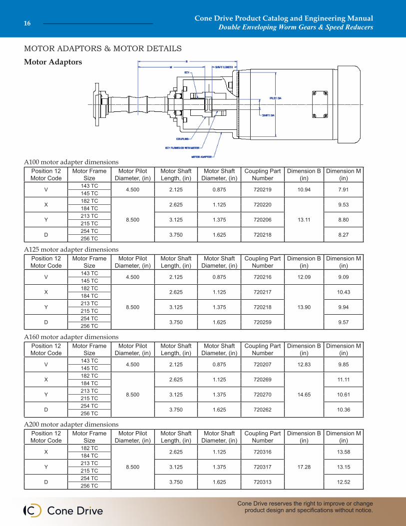
MOTOR ADAPTORS & MOTOR DETAILS
Motor Adaptors
Position 12 Motor Code
Motor Frame Size
Motor Pilot Diameter, (in)
Motor Shaft Length, (in)
Motor Shaft Diameter, (in)
Coupling Part Number
Dimension B (in)
Dimension M (in)
V143 TC
4.500 2.125 0.875 720219 10.94 7.91145 TC
X182 TC
8.500
2.625 1.125 720220
13.11
9.53184 TC
Y213 TC
3.125 1.375 720206 8.80215 TC
D254 TC
3.750 1.625 720218 8.27256 TC
A100 motor adapter dimensions
Position 12 Motor Code
Motor Frame Size
Motor Pilot Diameter, (in)
Motor Shaft Length, (in)
Motor Shaft Diameter, (in)
Coupling Part Number
Dimension B (in)
Dimension M (in)
V143 TC
4.500 2.125 0.875 720216 12.09 9.09145 TC
X182 TC
8.500
2.625 1.125 720217
13.90
10.43184 TC
Y213 TC
3.125 1.375 720218 9.94215 TC
D254 TC
3.750 1.625 720259 9.57256 TC
A125 motor adapter dimensions
Position 12 Motor Code
Motor Frame Size
Motor Pilot Diameter, (in)
Motor Shaft Length, (in)
Motor Shaft Diameter, (in)
Coupling Part Number
Dimension B (in)
Dimension M (in)
V143 TC
4.500 2.125 0.875 720207 12.83 9.85145 TC
X182 TC
8.500
2.625 1.125 720269
14.65
11.11184 TC
Y213 TC
3.125 1.375 720270 10.61215 TC
D254 TC
3.750 1.625 720262 10.36256 TC
A160 motor adapter dimensions
Position 12 Motor Code
Motor Frame Size
Motor Pilot Diameter, (in)
Motor Shaft Length, (in)
Motor Shaft Diameter, (in)
Coupling Part Number
Dimension B (in)
Dimension M (in)
X182 TC
8.500
2.625 1.125 720316
17.28
13.58184 TC
Y213 TC
3.125 1.375 720317 13.15215 TC
D254 TC
3.750 1.625 720313 12.52256 TC
A200 motor adapter dimensions
Cone Drive Product Catalog and Engineering ManualDouble Enveloping Worm Gears & Speed Reducers 17
Sales: 1-888-994-2663Sales Fax: 1-888-907-2663Traverse City, MI. 49685
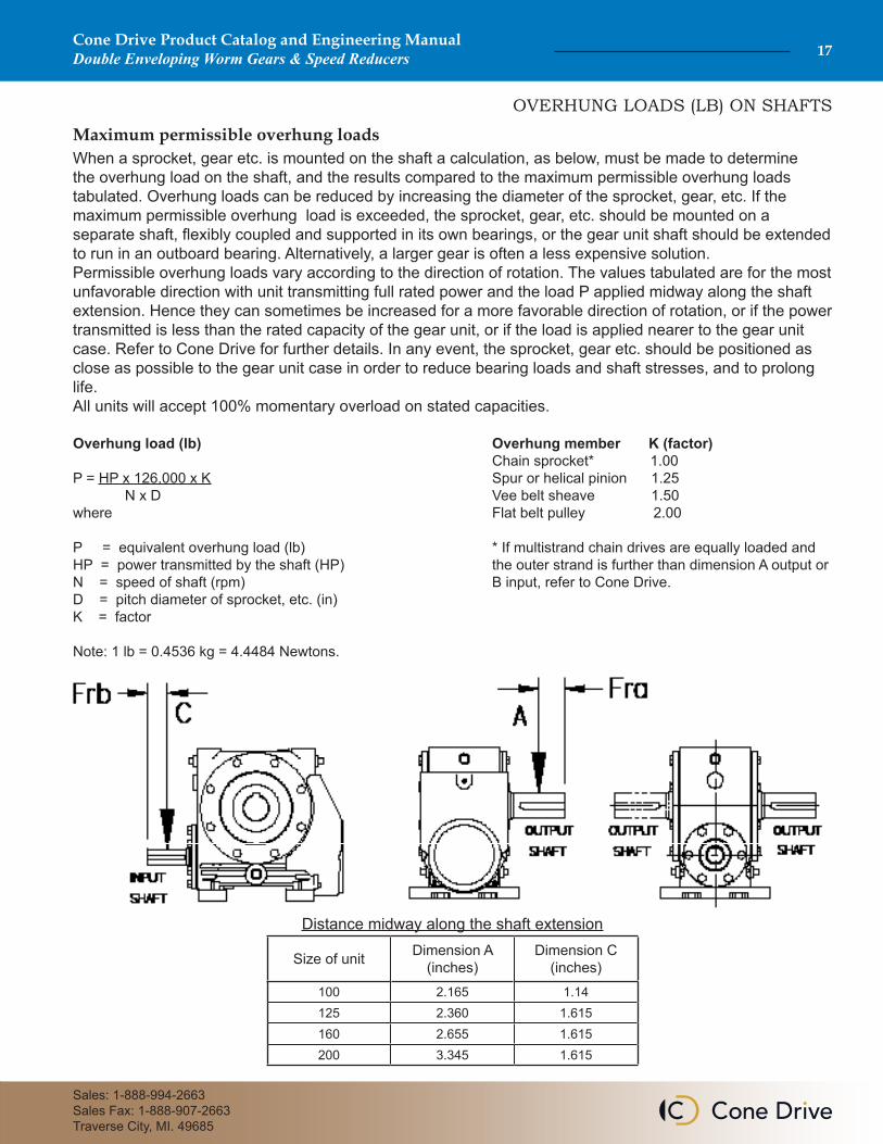
OVERHUNG LOADS (LB) ON SHAFTS
Maximum permissible overhung loadsWhen a sprocket, gear etc. is mounted on the shaft a calculation, as below, must be made to determine the overhung load on the shaft, and the results compared to the maximum permissible overhung loads tabulated. Overhung loads can be reduced by increasing the diameter of the sprocket, gear, etc. If the maximum permissible overhung load is exceeded, the sprocket, gear, etc. should be mounted on a separate shaft, flexibly coupled and supported in its own bearings, or the gear unit shaft should be extended to run in an outboard bearing. Alternatively, a larger gear is often a less expensive solution.Permissible overhung loads vary according to the direction of rotation. The values tabulated are for the most unfavorable direction with unit transmitting full rated power and the load P applied midway along the shaft extension. Hence they can sometimes be increased for a more favorable direction of rotation, or if the power transmitted is less than the rated capacity of the gear unit, or if the load is applied nearer to the gear unit case. Refer to Cone Drive for further details. In any event, the sprocket, gear etc. should be positioned as close as possible to the gear unit case in order to reduce bearing loads and shaft stresses, and to prolong life.All units will accept 100% momentary overload on stated capacities.
Overhung load (lb)
P = HP x 126,000 x K N x Dwhere
P = equivalent overhung load (lb)HP = power transmitted by the shaft (HP)N = speed of shaft (rpm)D = pitch diameter of sprocket, etc. (in)K = factor
Note: 1 lb = 0.4536 kg = 4.4484 Newtons.
Overhung member K (factor)Chain sprocket* 1.00Spur or helical pinion 1.25Vee belt sheave 1.50Flat belt pulley 2.00
* If multistrand chain drives are equally loaded and the outer strand is further than dimension A output or B input, refer to Cone Drive.
Distance midway along the shaft extension
Size of unit Dimension A (inches)
Dimension C (inches)
100 2.165 1.14125 2.360 1.615160 2.655 1.615200 3.345 1.615
Cone Drive Product Catalog and Engineering ManualDouble Enveloping Worm Gears & Speed Reducers18
Cone Drive reserves the right to improve or change product design and specifications without notice.
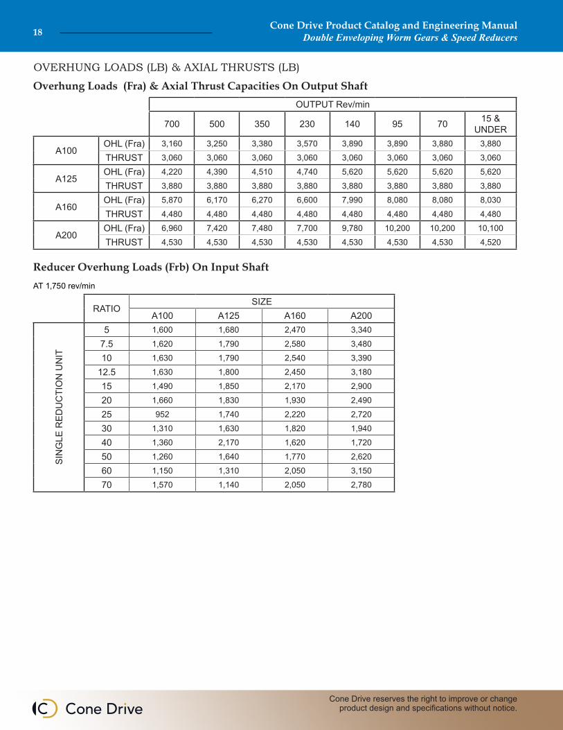
OVERHUNG LOADS (LB) & AXIAL THRUSTS (LB)
Overhung Loads (Fra) & Axial Thrust Capacities On Output ShaftOUTPUT Rev/min
700 500 350 230 140 95 70 15 & UNDER
A100OHL (Fra) 3,160 3,250 3,380 3,570 3,890 3,890 3,880 3,880
THRUST 3,060 3,060 3,060 3,060 3,060 3,060 3,060 3,060
A125OHL (Fra) 4,220 4,390 4,510 4,740 5,620 5,620 5,620 5,620
THRUST 3,880 3,880 3,880 3,880 3,880 3,880 3,880 3,880
A160OHL (Fra) 5,870 6,170 6,270 6,600 7,990 8,080 8,080 8,030
THRUST 4,480 4,480 4,480 4,480 4,480 4,480 4,480 4,480
A200OHL (Fra) 6,960 7,420 7,480 7,700 9,780 10,200 10,200 10,100
THRUST 4,530 4,530 4,530 4,530 4,530 4,530 4,530 4,520
Reducer Overhung Loads (Frb) On Input Shaft
RATIOSIZE
A100 A125 A160 A200
SIN
GLE
RED
UC
TIO
N U
NIT
5 1,600 1,680 2,470 3,340
7.5 1,620 1,790 2,580 3,480
10 1,630 1,790 2,540 3,390
12.5 1,630 1,800 2,450 3,180
15 1,490 1,850 2,170 2,900
20 1,660 1,830 1,930 2,490
25 952 1,740 2,220 2,720
30 1,310 1,630 1,820 1,940
40 1,360 2,170 1,620 1,720
50 1,260 1,640 1,770 2,620
60 1,150 1,310 2,050 3,150
70 1,570 1,140 2,050 2,780
AT 1,750 rev/min
Cone Drive Product Catalog and Engineering ManualDouble Enveloping Worm Gears & Speed Reducers 19
Sales: 1-888-994-2663Sales Fax: 1-888-907-2663Traverse City, MI. 49685
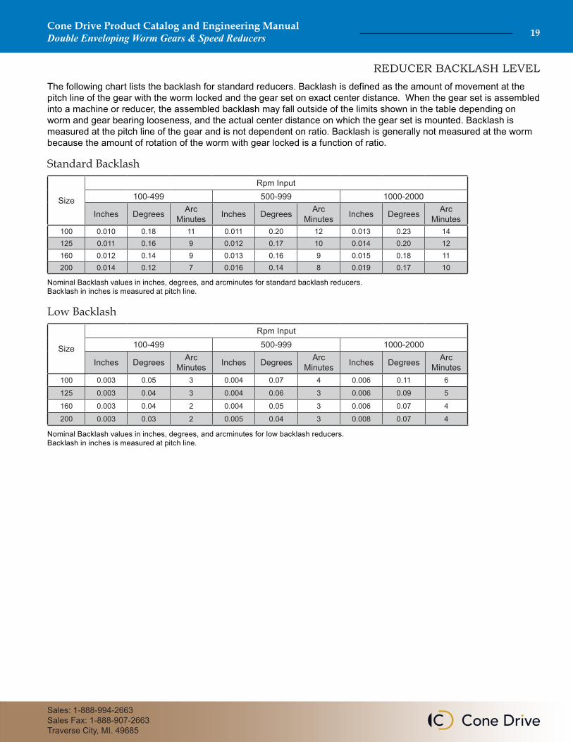
The following chart lists the backlash for standard reducers. Backlash is defined as the amount of movement at the pitch line of the gear with the worm locked and the gear set on exact center distance. When the gear set is assembled into a machine or reducer, the assembled backlash may fall outside of the limits shown in the table depending on worm and gear bearing looseness, and the actual center distance on which the gear set is mounted. Backlash is measured at the pitch line of the gear and is not dependent on ratio. Backlash is generally not measured at the worm because the amount of rotation of the worm with gear locked is a function of ratio.
Nominal Backlash values in inches, degrees, and arcminutes for standard backlash reducers. Backlash in inches is measured at pitch line.
Size
Rpm Input100-499 500-999 1000-2000
Inches Degrees Arc Minutes Inches Degrees Arc
Minutes Inches Degrees Arc Minutes
100 0.010 0.18 11 0.011 0.20 12 0.013 0.23 14125 0.011 0.16 9 0.012 0.17 10 0.014 0.20 12160 0.012 0.14 9 0.013 0.16 9 0.015 0.18 11200 0.014 0.12 7 0.016 0.14 8 0.019 0.17 10
Standard Backlash
Nominal Backlash values in inches, degrees, and arcminutes for low backlash reducers. Backlash in inches is measured at pitch line.
Size
Rpm Input100-499 500-999 1000-2000
Inches Degrees Arc Minutes Inches Degrees Arc
Minutes Inches Degrees Arc Minutes
100 0.003 0.05 3 0.004 0.07 4 0.006 0.11 6
125 0.003 0.04 3 0.004 0.06 3 0.006 0.09 5
160 0.003 0.04 2 0.004 0.05 3 0.006 0.07 4
200 0.003 0.03 2 0.005 0.04 3 0.008 0.07 4
Low Backlash
REDUCER BACKLASH LEVEL
Cone Drive Product Catalog and Engineering ManualDouble Enveloping Worm Gears & Speed Reducers20
Cone Drive reserves the right to improve or change product design and specifications without notice.
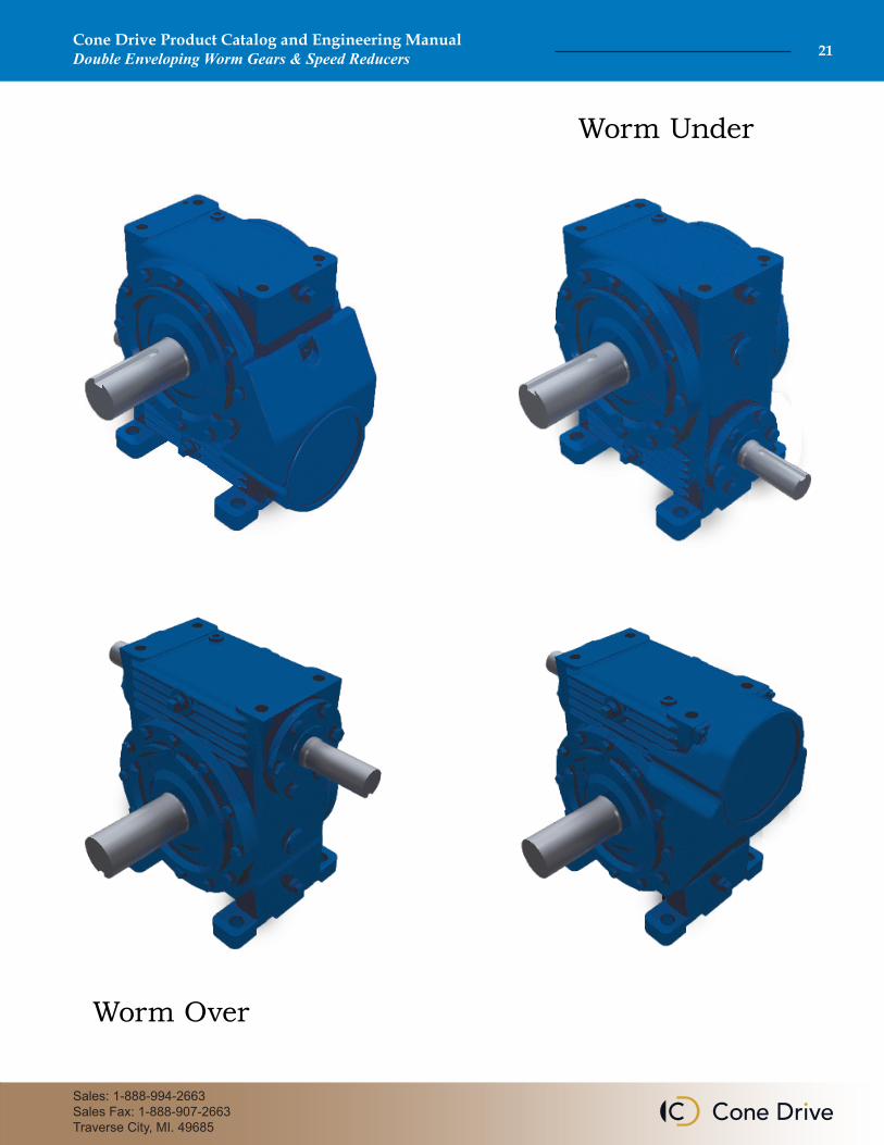
Worm Over
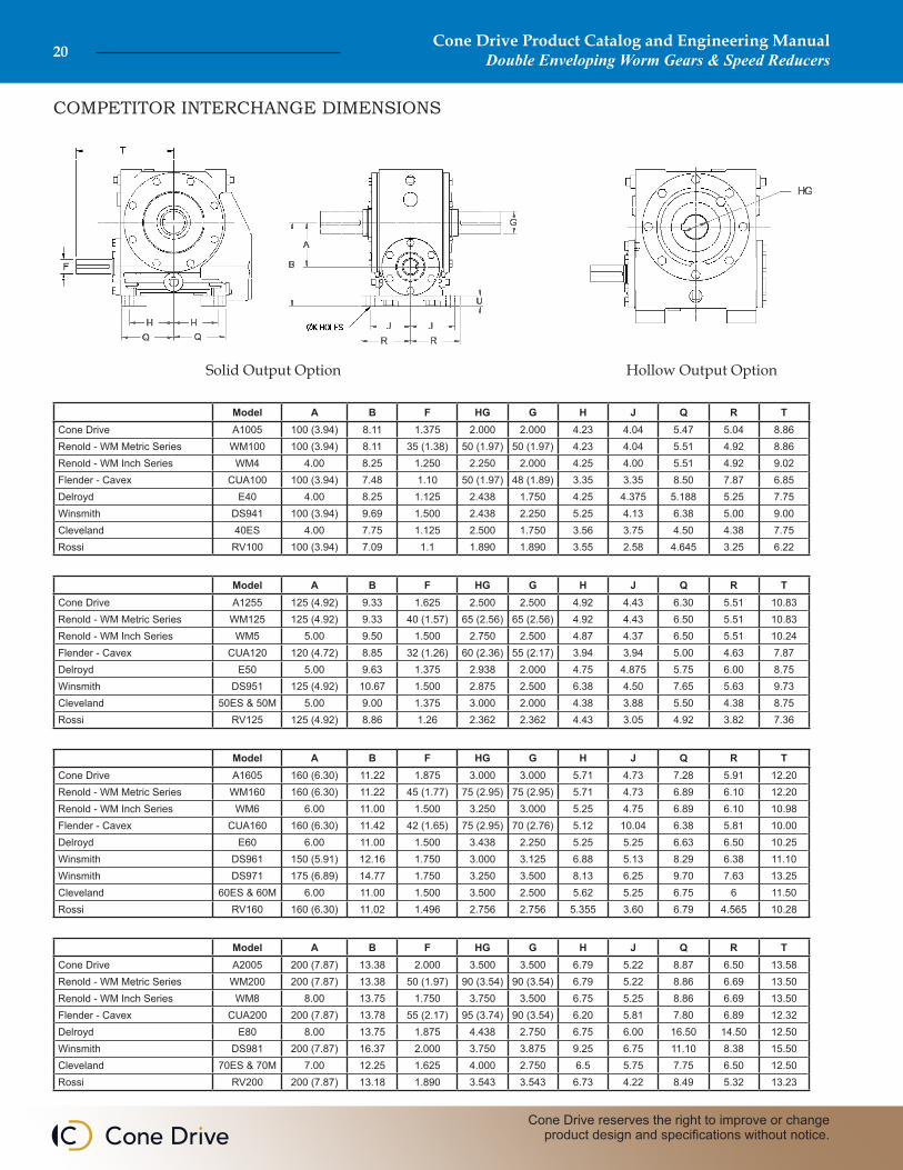
COMPETITOR INTERCHANGE DIMENSIONS
Model A B F HG G H J Q R TCone Drive A1005 100 (3.94) 8.11 1.375 2.000 2.000 4.23 4.04 5.47 5.04 8.86Renold - WM Metric Series WM100 100 (3.94) 8.11 35 (1.38) 50 (1.97) 50 (1.97) 4.23 4.04 5.51 4.92 8.86Renold - WM Inch Series WM4 4.00 8.25 1.250 2.250 2.000 4.25 4.00 5.51 4.92 9.02Flender - Cavex CUA100 100 (3.94) 7.48 1.10 50 (1.97) 48 (1.89) 3.35 3.35 8.50 7.87 6.85Delroyd E40 4.00 8.25 1.125 2.438 1.750 4.25 4.375 5.188 5.25 7.75Winsmith DS941 100 (3.94) 9.69 1.500 2.438 2.250 5.25 4.13 6.38 5.00 9.00Cleveland 40ES 4.00 7.75 1.125 2.500 1.750 3.56 3.75 4.50 4.38 7.75Rossi RV100 100 (3.94) 7.09 1.1 1.890 1.890 3.55 2.58 4.645 3.25 6.22
Model A B F HG G H J Q R TCone Drive A1255 125 (4.92) 9.33 1.625 2.500 2.500 4.92 4.43 6.30 5.51 10.83Renold - WM Metric Series WM125 125 (4.92) 9.33 40 (1.57) 65 (2.56) 65 (2.56) 4.92 4.43 6.50 5.51 10.83Renold - WM Inch Series WM5 5.00 9.50 1.500 2.750 2.500 4.87 4.37 6.50 5.51 10.24Flender - Cavex CUA120 120 (4.72) 8.85 32 (1.26) 60 (2.36) 55 (2.17) 3.94 3.94 5.00 4.63 7.87Delroyd E50 5.00 9.63 1.375 2.938 2.000 4.75 4.875 5.75 6.00 8.75Winsmith DS951 125 (4.92) 10.67 1.500 2.875 2.500 6.38 4.50 7.65 5.63 9.73Cleveland 50ES & 50M 5.00 9.00 1.375 3.000 2.000 4.38 3.88 5.50 4.38 8.75Rossi RV125 125 (4.92) 8.86 1.26 2.362 2.362 4.43 3.05 4.92 3.82 7.36
Model A B F HG G H J Q R TCone Drive A1605 160 (6.30) 11.22 1.875 3.000 3.000 5.71 4.73 7.28 5.91 12.20Renold - WM Metric Series WM160 160 (6.30) 11.22 45 (1.77) 75 (2.95) 75 (2.95) 5.71 4.73 6.89 6.10 12.20Renold - WM Inch Series WM6 6.00 11.00 1.500 3.250 3.000 5.25 4.75 6.89 6.10 10.98Flender - Cavex CUA160 160 (6.30) 11.42 42 (1.65) 75 (2.95) 70 (2.76) 5.12 10.04 6.38 5.81 10.00Delroyd E60 6.00 11.00 1.500 3.438 2.250 5.25 5.25 6.63 6.50 10.25Winsmith DS961 150 (5.91) 12.16 1.750 3.000 3.125 6.88 5.13 8.29 6.38 11.10Winsmith DS971 175 (6.89) 14.77 1.750 3.250 3.500 8.13 6.25 9.70 7.63 13.25Cleveland 60ES & 60M 6.00 11.00 1.500 3.500 2.500 5.62 5.25 6.75 6 11.50Rossi RV160 160 (6.30) 11.02 1.496 2.756 2.756 5.355 3.60 6.79 4.565 10.28
Model A B F HG G H J Q R TCone Drive A2005 200 (7.87) 13.38 2.000 3.500 3.500 6.79 5.22 8.87 6.50 13.58Renold - WM Metric Series WM200 200 (7.87) 13.38 50 (1.97) 90 (3.54) 90 (3.54) 6.79 5.22 8.86 6.69 13.50Renold - WM Inch Series WM8 8.00 13.75 1.750 3.750 3.500 6.75 5.25 8.86 6.69 13.50Flender - Cavex CUA200 200 (7.87) 13.78 55 (2.17) 95 (3.74) 90 (3.54) 6.20 5.81 7.80 6.89 12.32Delroyd E80 8.00 13.75 1.875 4.438 2.750 6.75 6.00 16.50 14.50 12.50Winsmith DS981 200 (7.87) 16.37 2.000 3.750 3.875 9.25 6.75 11.10 8.38 15.50Cleveland 70ES & 70M 7.00 12.25 1.625 4.000 2.750 6.5 5.75 7.75 6.50 12.50Rossi RV200 200 (7.87) 13.18 1.890 3.543 3.543 6.73 4.22 8.49 5.32 13.23
Solid Output Option Hollow Output Option
Cone Drive Product Catalog and Engineering ManualDouble Enveloping Worm Gears & Speed Reducers 21
Sales: 1-888-994-2663Sales Fax: 1-888-907-2663Traverse City, MI. 49685
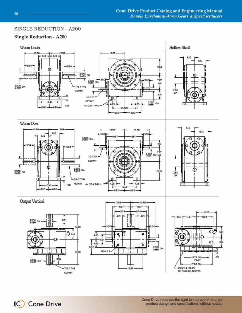
Worm Under
Worm Over
Cone Drive Product Catalog and Engineering ManualDouble Enveloping Worm Gears & Speed Reducers22
Cone Drive reserves the right to improve or change product design and specifications without notice.
SINGLE REDUCTION - A100
Single Reduction - A100

Cone Drive Product Catalog and Engineering ManualDouble Enveloping Worm Gears & Speed Reducers 23
Sales: 1-888-994-2663Sales Fax: 1-888-907-2663Traverse City, MI. 49685
SINGLE REDUCTION - A100
Worm RPM
Ratio Rating100 200 300 580 720 870 1150 1750
hp kw hp kw hp kw hp kw hp kw hp kw hp kw hp kw
5.1
Mechanical 4.17 3.11 7.65 5.70 10.71 7.99 17.14 12.78 19.34 14.42 21.28 15.87 24.85 18.53 30.46 22.71Thermal 4.17 3.11 6.81 5.07 7.55 5.63 7.57 5.65 7.62 5.68 8.53 6.36 8.56 6.38 8.56 6.38Fan Thermal NA NA NA NA NA NA 16.43 12.25 20.19 15.06Efficiency % 89 90 91 91 91 92 92 92O.T 11,997 1,355 11,129 1,257 10,509 1,187 8,702 983 7,914 894 7,286 823 6,436 727 5,185 586
7.4
Mechanical 3.53 2.63 6.45 4.81 9.10 6.79 14.80 11.04 16.79 12.52 18.58 13.86 21.56 16.08 26.75 19.95Thermal 3.53 2.63 5.56 4.15 6.05 4.51 6.32 4.71 6.93 5.17 7.31 5.45 7.70 5.74 7.70 5.74Fan Thermal NA NA NA NA NA NA 14.78 11.02 18.17 13.55Efficiency % 86 88 89 89 90 91 91 91O.T. 14,165 1,600 13,162 1,487 12,533 1,416 10,597 1,197 9,791 1,106 9,017 1,019 7,958 899 6,489 733
9.7
Mechanical 2.98 2.22 5.44 4.06 7.71 5.75 12.73 9.49 14.55 10.85 16.11 12.01 18.76 13.99 23.26 17.34Thermal 2.98 2.22 4.68 3.49 5.02 3.74 5.39 4.02 6.33 4.72 6.36 4.74 6.97 5.20 6.97 5.20Fan Thermal NA NA NA NA NA NA 13.37 9.97 16.44 12.26Efficiency % 83 85 86 87 89 89 90 90O.T 15,247 1,723 14,243 1,609 13,623 1,539 11,759 1,329 11,063 1,250 10,142 1,146 9,029 1,020 7,357 831
12.3
Mechanical 2.63 1.96 4.79 3.57 6.82 5.09 11.27 8.40 12.93 9.64 14.34 10.69 16.61 12.39 20.77 15.49Thermal 2.63 1.96 4.09 3.05 4.35 3.24 4.95 3.69 5.56 4.15 5.78 4.31 6.31 4.71 6.31 4.71Fan Thermal NA NA NA NA NA NA 12.11 9.03 14.89 11.10Efficiency % 81 83 84 86 88 88 89 89O.T. 16,593 1,875 15,473 1,748 14,859 1,679 12,990 1,468 12,221 1,381 11,281 1,275 9,997 1,129 8,212 928
15.5
Mechanical 2.31 1.72 4.21 3.14 6.00 4.47 9.94 7.41 11.41 8.51 12.67 9.45 14.69 10.95 18.34 13.68Thermal 2.31 1.72 3.56 2.65 3.75 2.80 4.54 3.39 4.83 3.60 5.15 3.84 5.56 4.15 5.61 4.18Fan Thermal NA NA NA NA NA NA 10.68 7.96 13.23 9.87Efficiency % 79 81 82 85 86 87 88 88O.T 17,766 2,007 16,584 1,874 15,935 1,800 14,190 1,603 13,263 1,498 12,313 1,391 10,925 1,234 8,977 1,014
19.5
Mechanical 1.87 1.39 3.41 2.54 4.84 3.61 8.05 6.00 9.25 6.90 10.27 7.66 11.92 8.89 14.86 11.08Thermal 1.87 1.39 3.05 2.28 3.19 2.38 4.11 3.06 4.13 3.08 4.16 3.10 4.42 3.30 4.69 3.50Fan Thermal NA NA NA NA NA NA 8.49 6.33 11.07 8.26Efficiency % 75 77 78 83 83 83 84 85O.T. 17,297 1,954 16,191 1,829 15,539 1,756 14,189 1,603 13,143 1,485 12,094 1,366 10,743 1,214 8,901 1,006
25.0
Mechanical 1.47 1.10 2.68 2.00 3.81 2.84 6.36 4.74 7.29 5.44 8.11 6.05 9.41 7.02 11.72 8.74Thermal 1.47 1.10 2.68 2.00 3.00 2.24 3.63 2.71 3.63 2.71 4.06 3.03 4.31 3.22 4.31 3.22Fan Thermal NA NA NA NA NA NA 8.28 6.17 10.17 7.59Efficiency % 71 75 77 81 81 83 84 84O.T 16,426 1,856 15,849 1,791 15,418 1,742 13,989 1,580 12,918 1,459 12,183 1,376 10,828 1,223 8,861 1,001
30.0
Mechanical 1.23 0.92 2.24 1.67 3.19 2.38 5.32 3.97 6.11 4.56 6.79 5.06 7.88 5.88 9.80 7.31Thermal 1.23 0.92 2.24 1.67 2.46 1.84 2.76 2.06 3.14 2.34 3.29 2.45 3.45 2.57 3.45 2.57Fan Thermal NA NA NA NA NA NA 6.62 4.94 8.14 6.07Efficiency % 68 70 72 75 78 79 80 80O.T. 15,787 1,784 14,845 1,677 14,468 1,635 12,999 1,469 12,511 1,413 11,651 1,316 10,363 1,171 8,471 957
40.0
Mechanical 0.93 0.69 1.69 1.26 2.41 1.80 4.01 2.99 4.60 3.43 5.12 3.82 5.95 4.44 7.39 5.51Thermal 0.93 0.69 1.69 1.26 2.09 1.56 2.46 1.84 2.76 2.06 2.76 2.06 2.88 2.14 2.88 2.14Fan Thermal NA NA NA NA NA NA 5.52 4.11 6.78 5.06Efficiency % 61 63 67 72 75 75 76 76O.T 14,247 1,610 13,420 1,516 13,547 1,531 12,534 1,416 12,083 1,365 11,124 1,257 9,916 1,120 8,092 914
50.0
Mechanical 0.74 0.55 1.36 1.01 1.93 1.44 3.21 2.39 3.69 2.75 4.11 3.06 4.78 3.56 5.93 4.42Thermal 0.74 0.55 1.36 1.01 1.92 1.43 2.30 1.72 2.46 1.84 2.46 1.84 2.56 1.91 2.56 1.91Fan Thermal NA NA NA NA NA NA 4.78 3.56 5.93 4.42Efficiency % 54 60 64 70 72 72 73 73O.T. 12,645 1,429 12,815 1,448 12,975 1,466 12,218 1,380 11,631 1,314 10,720 1,211 9,550 1,079 7,796 881
60.0
Mechanical 0.62 0.46 1.13 0.84 1.61 1.20 2.68 2.00 3.09 2.30 3.43 2.56 3.99 2.98 4.95 3.69Thermal 0.62 0.46 1.13 0.84 1.61 1.20 2.03 1.51 2.16 1.61 2.23 1.66 2.30 1.72 2.30 1.72Fan Thermal NA NA NA NA NA NA 3.99 2.98 4.95 3.69Efficiency % 53 59 61 66 68 69 70 70O.T 12,433 1,405 12,645 1,429 12,389 1,400 11,540 1,304 11,029 1,246 10,292 1,163 9,174 1,036 7,491 846
70.0
Mechanical 0.53 0.40 0.97 0.72 1.38 1.03 2.30 1.72 2.65 1.98 2.95 2.20 3.42 2.55 4.25 3.17Thermal 0.53 0.40 0.97 0.72 1.38 1.03 1.97 1.47 2.09 1.56 2.16 1.61 2.23 1.66 2.23 1.66Fan Thermal NA NA NA NA NA NA 3.42 2.55 4.25 3.17Efficiency % 52 58 60 65 67 68 69 69O.T. 12,214 1,380 12,446 1,406 12,201 1,378 11,380 1,286 10,880 1,229 10,155 1,147 9,054 1,023 7,393 835
Ratings shown are based on using the recommended synthetic lubricant (see approved lubricants)
Cone Drive Product Catalog and Engineering ManualDouble Enveloping Worm Gears & Speed Reducers24
Cone Drive reserves the right to improve or change product design and specifications without notice.
SINGLE REDUCTION - A125
Single Reduction - A125
Cone Drive Product Catalog and Engineering ManualDouble Enveloping Worm Gears & Speed Reducers 25
Sales: 1-888-994-2663Sales Fax: 1-888-907-2663Traverse City, MI. 49685
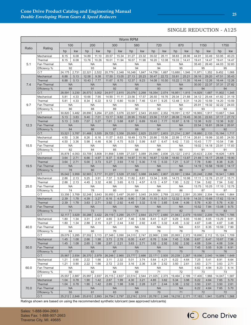
SINGLE REDUCTION - A125
Worm RPM
Ratio Rating100 200 300 580 720 870 1150 1750
hp kw hp kw hp kw hp kw hp kw hp kw hp kw hp kw
5.1
Mechanical 8.15 6.08 14.89 11.10 20.57 15.34 31.27 23.32 35.02 26.11 38.83 28.96 44.91 33.49 53.95 40.23Thermal 8.15 6.08 13.76 10.26 16.01 11.94 16.07 11.98 16.20 12.08 19.33 14.41 19.41 14.47 19.41 14.47Fan Thermal NA NA NA NA NA NA 35.40 26.40 44.03 32.83Efficiency % 92 93 94 94 94 95 95 95O.T 24,175 2,731 22,321 2,522 20,779 2,348 16,348 1,847 14,756 1,667 13,680 1,546 11,971 1,352 9,452 1,068
7.4
Mechanical 6.88 5.13 12.58 9.38 17.50 13.05 27.13 20.23 30.47 22.72 33.81 25.21 39.16 29.20 47.51 35.43Thermal 6.88 5.13 10.43 7.77 11.67 8.70 12.37 9.23 14.08 10.50 15.22 11.35 16.44 12.26 16.44 12.26Fan Thermal NA NA NA NA NA NA 30.00 22.37 37.31 27.82Efficiency % 89 91 92 92 93 94 94 94O.T. 28,591 3,230 26,573 3,002 24,917 2,815 20,076 2,268 18,354 2,074 16,951 1,915 14,929 1,687 11,902 1,345
9.7
Mechanical 5.81 4.33 10.66 7.95 14.90 11.11 23.56 17.57 26.50 19.76 29.34 21.88 34.12 25.44 41.82 31.19Thermal 5.81 4.33 8.34 6.22 9.12 6.80 10.00 7.46 12.41 9.25 12.48 9.31 14.20 10.59 14.20 10.59Fan Thermal NA NA NA NA NA NA 25.91 19.32 32.22 24.03Efficiency % 86 88 89 90 92 92 93 93O.T 30,820 3,482 28,890 3,264 27,225 3,076 22,507 2,543 20,820 2,352 19,091 2,157 16,965 1,917 13,667 1,544
12.3
Mechanical 5.13 3.83 9.40 7.01 13.17 9.82 20.95 15.62 23.56 17.57 26.08 19.45 30.35 22.63 37.17 27.72Thermal 5.13 3.83 7.07 5.27 7.61 5.68 8.97 6.69 10.43 7.77 10.97 8.18 12.36 9.22 12.36 9.22Fan Thermal NA NA NA NA NA NA 22.54 16.81 28.04 20.91Efficiency % 84 86 87 89 91 91 92 92O.T. 33,521 3,787 31,468 3,555 29,725 3,358 25,000 2,825 23,037 2,603 21,214 2,397 18,880 2,133 15,194 1,717
15.5
Mechanical 4.50 3.36 8.26 6.16 11.57 8.63 18.49 13.79 20.86 15.56 22.99 17.14 26.81 19.99 32.85 24.50Thermal 4.50 3.36 5.98 4.46 6.36 4.75 8.03 5.99 8.67 6.47 9.42 7.03 10.43 7.77 10.54 7.86Fan Thermal NA NA NA NA NA NA 19.02 14.18 23.91 17.83Efficiency % 82 84 85 88 89 90 91 91O.T 35,878 4,053 33,709 3,808 31,858 3,599 27,337 3,089 25,098 2,836 23,122 2,612 20,623 2,330 16,626 1,878
19.5
Mechanical 3.64 2.71 6.66 4.97 9.37 6.99 14.97 11.16 16.87 12.58 18.60 13.87 21.69 16.17 26.68 19.90Thermal 3.64 2.71 5.00 3.73 5.27 3.93 7.10 5.30 7.15 5.33 7.21 5.37 7.78 5.80 8.38 6.25Fan Thermal NA NA NA NA NA NA 14.19 10.58 19.00 14.17Efficiency % 78 80 81 86 86 86 87 88O.T. 35,042 3,959 32,903 3,717 31,227 3,528 27,332 3,088 24,845 2,807 22,691 2,564 20,248 2,288 16,541 1,869
25.0
Mechanical 2.86 2.13 5.25 3.91 7.37 5.50 11.82 8.81 13.34 9.95 14.73 10.98 17.11 12.76 21.07 15.71Thermal 2.86 2.13 4.45 3.32 4.90 3.65 6.13 4.57 6.13 4.57 7.00 5.22 7.54 5.62 7.54 5.62Fan Thermal NA NA NA NA NA NA 13.75 10.25 17.10 12.75Efficiency % 74 78 80 84 84 86 87 87O.T 33,356 3,769 32,248 3,643 30,950 3,497 26,951 3,045 24,509 2,769 22,932 2,591 20,389 2,304 16,498 1,864
30.0
Mechanical 2.39 1.78 4.39 3.27 6.16 4.59 9.90 7.38 11.15 8.31 12.32 9.19 14.33 10.69 17.62 13.14Thermal 2.39 1.78 3.63 2.71 3.92 2.92 4.45 3.32 5.16 3.85 5.44 4.06 5.76 4.30 5.76 4.30Fan Thermal NA NA NA NA NA NA 10.52 7.84 13.08 9.75Efficiency % 71 73 75 78 81 82 83 83O.T. 32,117 3,629 30,288 3,422 29,119 3,290 25,171 2,844 23,717 2,680 21,943 2,479 19,550 2,209 15,795 1,785
40.0
Mechanical 1.80 1.34 3.31 2.47 4.65 3.47 7.46 5.56 8.41 6.27 9.29 6.93 10.80 8.05 13.29 9.91Thermal 1.80 1.34 2.88 2.15 3.27 2.44 3.92 2.92 4.45 3.32 4.45 3.32 4.67 3.48 4.67 3.48Fan Thermal NA NA NA NA NA NA 8.51 6.35 10.59 7.90Efficiency % 64 66 70 75 78 78 79 79O.T 29,079 3,285 27,552 3,113 27,348 3,090 24,310 2,747 22,968 2,595 20,993 2,372 18,690 2,112 15,124 1,709
50.0
Mechanical 1.45 1.08 2.66 1.98 3.73 2.78 6.00 4.47 6.76 5.04 7.45 5.56 8.67 6.47 10.67 7.96Thermal 1.45 1.08 2.65 1.98 2.97 2.21 3.63 2.71 3.92 2.92 3.92 2.92 4.08 3.04 4.08 3.04Fan Thermal NA NA NA NA NA NA 7.45 5.55 9.26 6.91Efficiency % 57 63 67 73 75 75 76 76O.T. 25,967 2,934 26,370 2,979 26,246 2,965 23,777 2,686 22,171 2,505 20,239 2,287 18,056 2,040 14,599 1,649
60.0
Mechanical 1.21 0.90 2.22 1.66 3.11 2.32 5.01 3.74 5.64 4.21 6.22 4.64 7.25 5.41 8.91 6.64Thermal 1.21 0.90 2.22 1.66 2.72 2.03 3.16 2.36 3.38 2.52 3.50 2.61 3.63 2.71 3.63 2.71Fan Thermal NA NA NA NA NA NA 6.62 4.94 8.23 6.14Efficiency % 56 62 64 69 71 72 73 73O.T 25,557 2,887 25,997 2,937 25,115 2,837 22,514 2,544 21,025 2,375 19,464 2,199 17,400 1,966 14,047 1,587
70.0
Mechanical 1.04 0.78 1.90 1.42 2.67 1.99 4.30 3.21 4.85 3.62 5.34 3.98 6.22 4.64 7.65 5.70Thermal 1.04 0.78 1.90 1.42 2.65 1.98 3.06 2.28 3.27 2.44 3.38 2.52 3.50 2.61 3.50 2.61Fan Thermal NA NA NA NA NA NA 6.22 4.64 7.65 5.70Efficiency % 55 61 63 68 70 71 72 72O.T. 25,212 2,848 25,610 2,893 24,754 2,797 22,216 2,510 20,781 2,348 19,218 2,171 17,183 1,941 13,878 1,568
Ratings shown are based on using the recommended synthetic lubricant (see approved lubricants)
Cone Drive Product Catalog and Engineering ManualDouble Enveloping Worm Gears & Speed Reducers26
Cone Drive reserves the right to improve or change product design and specifications without notice.
SINGLE REDUCTION - A160
Single Reduction - A160

Cone Drive Product Catalog and Engineering ManualDouble Enveloping Worm Gears & Speed Reducers 27
Sales: 1-888-994-2663Sales Fax: 1-888-907-2663Traverse City, MI. 49685
SINGLE REDUCTION - A160
Worm RPM
Ratio Rating100 200 300 580 720 870 1150 1750
hp kw hp kw hp kw hp kw hp kw hp kw hp kw hp kw
5.1
Mechanical 14.97 11.16 26.71 19.92 35.61 26.55 51.64 38.51 57.84 43.13 63.39 47.27 71.91 53.62 82.83 61.77Thermal 14.85 11.07 16.99 12.67 19.77 14.74 19.84 14.79 20.00 14.91 23.87 17.80 23.96 17.87 23.96 17.87Fan Thermal NA NA NA NA NA NA 47.20 35.20 58.02 43.27Efficiency % 92 93 94 94 94 95 95 95O.T 44,387 5,015 40,049 4,525 35,982 4,065 26,994 3,050 24,369 2,753 22,333 2,523 19,170 2,166 14,511 1,639
7.5
Mechanical 12.49 9.31 22.50 16.78 30.40 22.67 44.36 33.08 49.76 37.11 54.88 40.92 62.81 46.84 72.82 54.30Thermal 10.91 8.14 12.64 9.43 14.12 10.53 15.01 11.19 17.21 12.83 18.50 13.80 20.07 14.96 20.07 14.96Fan Thermal NA NA NA NA NA NA 39.53 29.48 48.59 36.24Efficiency % 89 90 91 92 93 93 94 94O.T. 52,991 5,987 48,532 5,483 44,198 4,993 33,543 3,790 30,648 3,463 28,122 3,177 24,480 2,766 18,653 2,107
9.8
Mechanical 10.65 7.94 19.31 14.40 26.35 19.65 39.08 29.14 43.97 32.79 48.62 36.26 55.69 41.53 64.86 48.37Thermal 8.79 6.56 10.25 7.65 11.20 8.35 12.30 9.17 15.28 11.39 15.36 11.45 17.49 13.04 17.49 13.04Fan Thermal NA NA NA NA NA NA 34.45 25.69 42.34 31.57Efficiency % 86 88 89 90 92 92 93 93O.T 56,696 6,406 52,564 5,939 48,363 5,464 37,503 4,237 34,714 3,922 31,787 3,591 27,828 3,144 21,300 2,406
12.2
Mechanical 9.47 7.06 17.19 12.82 23.51 17.53 35.01 26.11 39.44 29.41 43.60 32.51 49.99 37.28 58.80 43.85Thermal 7.66 5.71 8.77 6.54 9.45 7.05 11.10 8.28 12.94 9.65 13.60 10.14 15.32 11.42 15.32 11.42Fan Thermal NA NA NA NA NA NA 30.17 22.50 37.09 27.66Efficiency % 84 86 87 89 91 91 92 92O.T. 61,569 6,956 57,168 6,459 52,747 5,959 41,505 4,689 38,318 4,329 35,233 3,981 30,899 3,491 23,884 2,698
14.6
Mechanical 8.65 6.45 15.71 11.71 21.55 16.07 32.14 23.97 36.18 26.98 40.02 29.84 45.95 34.26 54.17 40.39Thermal 6.82 5.09 7.69 5.74 8.21 6.13 10.19 7.60 11.20 8.35 12.26 9.14 13.64 10.17 13.64 10.17Fan Thermal NA NA NA NA NA NA 26.87 20.04 33.03 24.63Efficiency % 82 84 85 88 89 90 91 91O.T 65,722 7,425 61,179 6,912 56,596 6,394 45,129 5,099 41,421 4,680 38,308 4,328 33,650 3,802 26,067 2,945
20.5
Mechanical 6.40 4.77 11.63 8.67 15.98 11.92 23.90 17.82 26.92 20.07 29.74 22.18 34.22 25.52 40.40 30.13Thermal 5.40 4.03 5.99 4.47 6.34 4.72 8.52 6.35 8.52 6.35 8.64 6.44 9.31 6.94 10.00 7.46Fan Thermal NA NA NA NA NA NA 18.34 13.67 24.22 18.06Efficiency % 78 80 81 86 86 86 87 88O.T. 64,110 7,243 59,924 6,770 55,660 6,288 45,652 5,158 41,427 4,680 37,971 4,290 33,439 3,778 26,210 2,961
24.5
Mechanical 5.38 4.01 9.77 7.29 13.43 10.01 20.16 15.03 22.65 16.89 25.05 18.68 28.82 21.49 34.08 25.41Thermal 4.73 3.52 5.55 4.14 6.08 4.53 7.66 5.71 7.66 5.71 8.64 6.44 9.31 6.94 9.38 6.99Fan Thermal NA NA NA NA NA NA 18.34 13.67 22.71 16.94Efficiency % 74 78 80 84 84 86 87 87O.T 61,726 6,974 58,971 6,663 55,342 6,253 45,164 5,103 40,885 4,619 38,227 4,319 33,652 3,802 26,177 2,957
30.0
Mechanical 4.41 3.29 8.03 5.99 11.03 8.23 16.55 12.34 18.60 13.87 20.58 15.35 23.65 17.64 28.02 20.89Thermal 4.17 3.11 4.48 3.34 4.84 3.61 5.50 4.10 6.37 4.75 6.72 5.01 7.12 5.31 7.12 5.31Fan Thermal NA NA NA NA NA NA 14.02 10.46 17.24 12.85Efficiency % 71 73 75 78 81 82 83 83O.T. 59,139 6,682 55,369 6,256 52,128 5,889 42,058 4,752 39,543 4,468 36,661 4,142 32,267 3,646 25,113 2,837
40.0
Mechanical 3.32 2.48 6.06 4.52 8.31 6.20 12.47 9.30 14.01 10.45 15.52 11.57 17.85 13.31 21.13 15.76Thermal 3.32 2.48 3.56 2.65 4.03 3.01 4.84 3.61 5.50 4.10 5.50 4.10 5.76 4.30 5.76 4.30Fan Thermal NA NA NA NA NA NA 11.35 8.46 13.95 10.40Efficiency % 64 66 70 75 78 78 79 79O.T 53,544 6,049 50,372 5,691 48,868 5,521 40,620 4,589 38,247 4,321 35,070 3,962 30,902 3,491 24,041 2,716
50.0
Mechanical 2.66 1.98 4.86 3.62 6.67 4.97 10.01 7.46 11.24 8.38 12.46 9.29 14.33 10.69 16.97 12.65Thermal 2.66 1.98 3.27 2.44 3.67 2.73 4.48 3.34 4.84 3.61 4.84 3.61 5.04 3.76 5.04 3.76Fan Thermal NA NA NA NA NA NA 9.93 7.41 12.21 9.10Efficiency % 57 63 67 73 75 75 76 76O.T. 47,815 5,402 48,210 5,447 46,898 5,299 39,692 4,484 36,873 4,166 33,832 3,822 29,829 3,370 23,221 2,624
60.0
Mechanical 2.22 1.66 4.06 3.03 5.57 4.15 8.36 6.23 9.38 6.99 10.41 7.76 11.97 8.93 14.18 10.57Thermal 2.22 1.66 3.18 2.37 3.36 2.51 3.90 2.91 4.17 3.11 4.32 3.22 4.48 3.34 4.48 3.34Fan Thermal NA NA NA NA NA NA 8.83 6.58 10.85 8.09Efficiency % 56 62 64 69 71 72 73 73O.T 47,059 5,317 47,529 5,370 44,877 5,070 37,583 4,246 34,968 3,951 32,556 3,678 28,722 3,245 22,364 2,527
70.0
Mechanical 1.91 1.42 3.48 2.60 4.79 3.57 7.17 5.35 8.05 6.00 8.93 6.66 10.28 7.67 12.18 9.08Thermal 1.91 1.42 3.10 2.31 3.27 2.44 3.78 2.82 4.03 3.01 4.17 3.11 4.32 3.22 4.32 3.22Fan Thermal NA NA NA NA NA NA 8.51 6.35 10.46 7.80Efficiency % 55 61 63 68 70 71 72 72O.T. 46,353 5,237 46,821 5,290 44,319 5,007 37,085 4,190 34,519 3,900 32,144 3,632 28,385 3,207 22,106 2,498
Ratings shown are based on using the recommended synthetic lubricant (see approved lubricants)
Cone Drive Product Catalog and Engineering ManualDouble Enveloping Worm Gears & Speed Reducers28
Cone Drive reserves the right to improve or change product design and specifications without notice.
SINGLE REDUCTION - A200
Single Reduction - A200

Cone Drive Product Catalog and Engineering ManualDouble Enveloping Worm Gears & Speed Reducers 29
Sales: 1-888-994-2663Sales Fax: 1-888-907-2663Traverse City, MI. 49685
SINGLE REDUCTION - A200
Worm RPM
Ratio Rating100 200 300 580 720 870 1150 1750
hp kw hp kw hp kw hp kw hp kw hp kw hp kw hp kw
5.1
Mechanical 29.09 21.69 51.22 38.19 67.15 50.07 95.91 71.52 107.12 79.88 117.46 87.59 131.20 97.84 151.57 113.03Thermal 25.35 18.90 28.99 21.62 33.75 25.16 33.86 25.25 34.08 25.41 40.68 30.34 40.84 30.46 40.84 30.46Fan Thermal NA NA NA NA NA NA 77.30 57.65 95.02 70.86Efficiency % 92 93 94 94 94 95 95 95O.T 85,874 9,702 76,444 8,637 67,532 7,630 49,899 5,638 44,913 5,074 41,183 4,653 34,809 3,933 26,426 2,986
7.5
Mechanical 24.20 18.05 43.18 32.20 57.56 42.92 83.16 62.01 93.26 69.54 102.31 76.29 115.94 86.46 133.28 99.39Thermal 18.56 13.84 21.51 16.04 24.02 17.91 25.54 19.05 29.28 21.84 31.48 23.47 34.14 25.46 34.14 25.46Fan Thermal NA NA NA NA NA NA 64.61 48.18 79.42 59.23Efficiency % 89 90 91 92 93 93 94 94O.T. 102,633 11,595 93,121 10,521 83,669 9,453 62,878 7,104 57,444 6,490 52,424 5,923 45,190 5,106 34,139 3,857
9.8
Mechanical 20.77 15.49 37.48 27.95 50.76 37.85 74.21 55.34 83.32 62.13 91.95 68.57 104.93 78.25 121.87 90.88Thermal 14.96 11.16 17.45 13.01 19.06 14.21 20.92 15.60 25.99 19.38 26.12 19.48 29.75 22.18 29.75 22.18Fan Thermal NA NA NA NA NA NA 56.30 41.98 69.21 51.61Efficiency % 86 88 89 90 92 92 93 93O.T 110,570 12,492 102,041 11,529 93,186 10,528 71,226 8,047 65,786 7,433 60,108 6,791 52,437 5,924 40,021 4,522
12.2
Mechanical 18.48 13.78 33.37 24.88 45.41 33.86 66.60 49.66 74.88 55.84 83.05 61.93 94.76 70.66 110.29 82.24Thermal 13.03 9.72 14.92 11.12 16.08 11.99 18.89 14.08 22.02 16.42 23.13 17.25 26.06 19.43 26.06 19.43Fan Thermal NA NA NA NA NA NA 49.32 36.78 60.62 45.21Efficiency % 84 86 87 89 91 91 92 92O.T. 120,078 13,566 110,988 12,539 101,860 11,508 78,964 8,921 72,759 8,220 67,114 7,583 58,566 6,617 44,794 5,061
15.3
Mechanical 16.36 12.20 29.61 22.08 40.31 30.06 59.57 44.42 66.96 49.93 74.14 55.29 84.75 63.20 98.47 73.43Thermal 11.27 8.40 12.65 9.43 13.48 10.05 16.97 12.66 18.38 13.71 20.04 14.95 22.21 16.56 22.38 16.69Fan Thermal NA NA NA NA NA NA 42.03 31.34 52.06 38.82Efficiency % 82 84 85 88 89 90 91 91O.T 129,176 14,594 119,744 13,529 109,995 12,427 87,170 9,848 79,778 9,013 73,869 8,346 64,590 7,297 49,352 5,576
20.5
Mechanical 12.48 9.31 22.62 16.87 30.87 23.02 45.66 34.05 51.29 38.25 56.86 42.40 65.15 48.58 75.78 56.51Thermal 9.19 6.85 10.19 7.60 10.78 8.04 14.50 10.81 14.50 10.81 14.70 10.96 15.83 11.81 17.01 12.69Fan Thermal NA NA NA NA NA NA 29.97 22.35 39.58 29.52Efficiency % 78 80 81 86 86 86 87 88O.T. 125,037 14,127 116,561 13,169 107,504 12,146 87,243 9,857 78,934 8,918 72,594 8,202 63,656 7,192 49,158 5,554
24.5
Mechanical 10.50 7.83 19.01 14.18 25.99 19.38 38.52 28.72 43.35 32.33 47.90 35.72 54.87 40.92 63.95 47.69Thermal 8.04 6.00 9.44 7.04 10.34 7.71 13.03 9.72 13.03 9.72 14.70 10.96 15.83 11.81 15.96 11.90Fan Thermal NA NA NA NA NA NA 29.97 22.35 37.13 27.68Efficiency % 74 78 80 84 84 86 87 87O.T 120,589 13,624 114,707 12,960 107,108 12,101 86,319 9,752 78,244 8,840 73,087 8,257 64,066 7,238 49,128 5,550
30.0
Mechanical 8.61 6.42 15.61 11.64 21.35 15.92 31.63 23.59 35.59 26.54 39.38 29.37 45.08 33.62 52.58 39.21Thermal 7.10 5.29 7.62 5.69 8.23 6.14 9.36 6.98 10.83 8.08 11.44 8.53 12.11 9.03 12.11 9.03Fan Thermal NA NA NA NA NA NA 22.92 17.09 28.17 21.01Efficiency % 71 73 75 78 81 82 83 83O.T. 115,535 13,053 107,703 12,168 100,890 11,399 80,386 9,082 75,679 8,550 70,142 7,925 61,498 6,948 47,137 5,326
40.0
Mechanical 6.49 4.84 11.76 8.77 16.09 12.00 23.86 17.79 26.85 20.02 29.70 22.15 34.04 25.38 39.71 29.61Thermal 5.72 4.26 6.05 4.51 6.86 5.12 8.23 6.14 9.36 6.98 9.36 6.98 9.80 7.31 9.80 7.31Fan Thermal NA NA NA NA NA NA 18.55 13.83 22.81 17.01Efficiency % 64 66 70 75 78 78 79 79O.T 104,605 11,818 97,806 11,050 94,580 10,686 77,739 8,783 73,305 8,282 67,101 7,581 58,923 6,657 45,171 5,103
50.0
Mechanical 5.20 3.88 9.43 7.03 12.90 9.62 19.16 14.29 21.60 16.11 23.84 17.78 27.34 20.39 31.93 23.81Thermal 4.79 3.57 5.56 4.15 6.24 4.65 7.62 5.69 8.23 6.14 8.23 6.14 8.58 6.40 8.58 6.40Fan Thermal NA NA NA NA NA NA 16.23 12.11 19.96 14.88Efficiency % 57 63 67 73 75 75 76 76O.T. 93,411 10,554 93,608 10,576 90,767 10,255 75,966 8,583 70,878 8,008 64,732 7,313 56,918 6,431 43,675 4,934
60.0
Mechanical 4.34 3.24 7.88 5.88 10.77 8.03 16.00 11.93 18.03 13.44 19.91 14.85 22.84 17.03 26.68 19.90Thermal 4.34 3.24 5.42 4.04 5.72 4.26 6.64 4.95 7.10 5.29 7.35 5.48 7.62 5.69 7.62 5.69Fan Thermal NA NA NA NA NA NA 14.43 10.76 17.74 13.23Efficiency % 56 62 64 69 71 72 73 73O.T 91,934 10,387 92,285 10,426 86,856 9,813 71,931 8,127 67,216 7,594 62,292 7,038 54,808 6,192 42,065 4,753
70.0
Mechanical 3.73 2.78 6.76 5.04 9.26 6.91 13.73 10.24 15.48 11.54 17.09 12.74 19.60 14.62 22.92 17.09Thermal 3.73 2.78 5.28 3.94 5.56 4.15 6.43 4.80 6.86 5.12 7.10 5.29 7.35 5.48 7.35 5.48Fan Thermal NA NA NA NA NA NA 13.91 10.38 17.10 12.75Efficiency % 55 61 63 68 70 71 72 72O.T. 90,557 10,231 90,911 10,271 85,780 9,691 70,978 8,019 66,353 7,497 61,505 6,949 54,126 6,115 41,581 4,698
Ratings shown are based on using the recommended synthetic lubricant (see approved lubricants)
Cone Drive Product Catalog and Engineering ManualDouble Enveloping Worm Gears & Speed Reducers30
Cone Drive reserves the right to improve or change product design and specifications without notice.
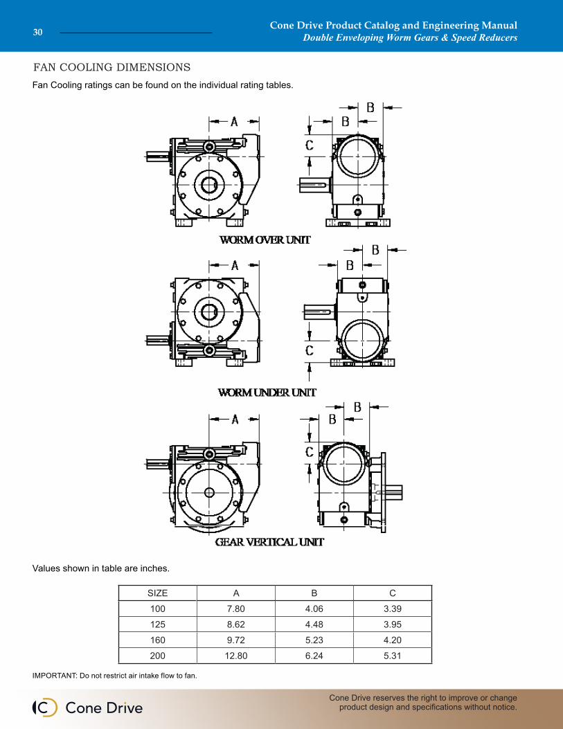
FAN COOLING DIMENSIONSFan Cooling ratings can be found on the individual rating tables.
Values shown in table are inches.
IMPORTANT: Do not restrict air intake flow to fan.
SIZE A B C100 7.80 4.06 3.39125 8.62 4.48 3.95160 9.72 5.23 4.20200 12.80 6.24 5.31
Cone Drive Product Catalog and Engineering ManualDouble Enveloping Worm Gears & Speed Reducers 31
Sales: 1-888-994-2663Sales Fax: 1-888-907-2663Traverse City, MI. 49685
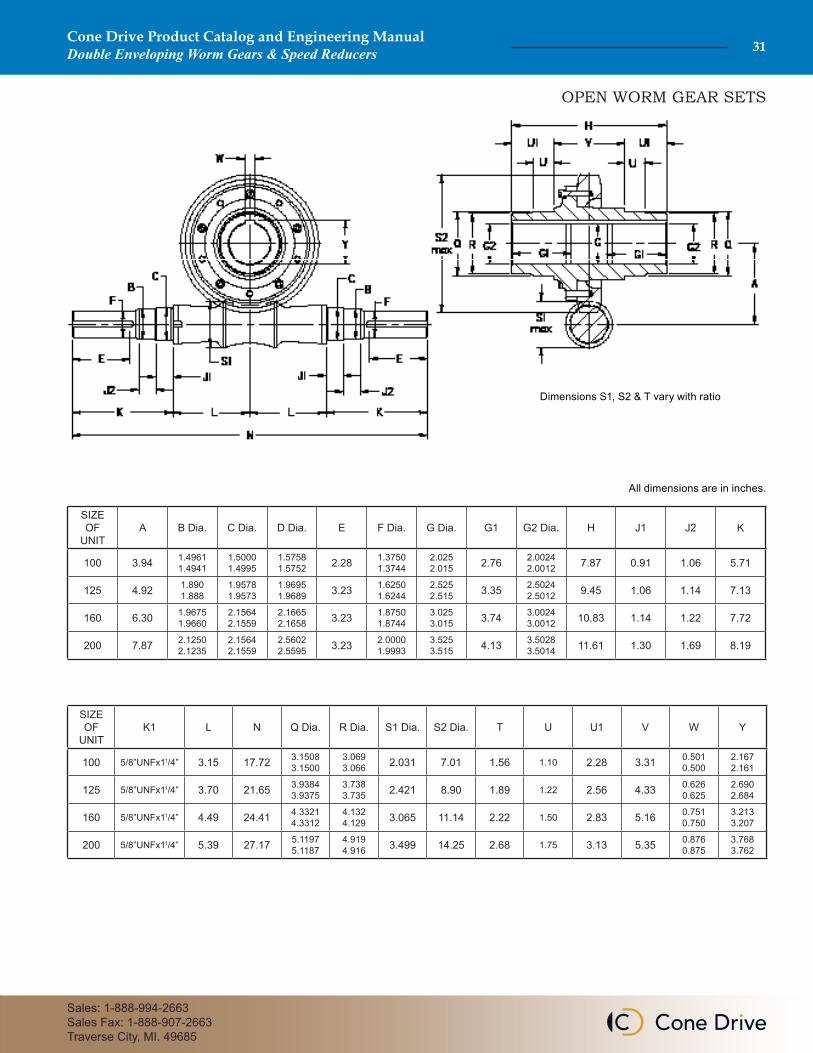
OPEN WORM GEAR SETS
SIZE OF
UNITA B Dia. C Dia. D Dia. E F Dia. G Dia. G1 G2 Dia. H J1 J2 K
100 3.94 1.49611.4941
1.50001.4995
1.57581.5752 2.28 1.3750
1.37442.0252.015 2.76 2.0024
2.0012 7.87 0.91 1.06 5.71
125 4.92 1.8901.888
1.95781.9573
1.96951.9689 3.23 1.6250
1.62442.5252.515 3.35 2.5024
2.5012 9.45 1.06 1.14 7.13
160 6.30 1.96751.9660
2.15642.1559
2.16652.1658 3.23 1.8750
1.87443.0253.015 3.74 3.0024
3.0012 10.83 1.14 1.22 7.72
200 7.87 2.12502.1235
2.15642.1559
2.56022.5595 3.23 2.0000
1.99933.5253.515 4.13 3.5028
3.5014 11.61 1.30 1.69 8.19
SIZE OF
UNITK1 L N Q Dia. R Dia. S1 Dia. S2 Dia. T U U1 V W Y
100 5/8”UNFx11/4” 3.15 17.72 3.15083.1500
3.0693.066 2.031 7.01 1.56 1.10 2.28 3.31 0.501
0.5002.1672.161
125 5/8”UNFx11/4” 3.70 21.65 3.93843.9375
3.7383.735 2.421 8.90 1.89 1.22 2.56 4.33 0.626
0.6252.6902.684
160 5/8”UNFx11/4” 4.49 24.41 4.33214.3312
4.1324.129 3.065 11.14 2.22 1.50 2.83 5.16 0.751
0.7503.2133.207
200 5/8”UNFx11/4” 5.39 27.17 5.11975.1187
4.9194.916 3.499 14.25 2.68 1.75 3.13 5.35 0.876
0.8753.7683.762
Dimensions S1, S2 & T vary with ratio
All dimensions are in inches.
Cone Drive Product Catalog and Engineering ManualDouble Enveloping Worm Gears & Speed Reducers32
Cone Drive reserves the right to improve or change product design and specifications without notice.
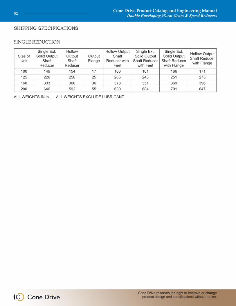
SHIPPING SPECIFICATIONS
SINGLE REDUCTION
ALL WEIGHTS IN lb. ALL WEIGHTS EXCLUDE LUBRICANT.
Size of Unit
Single Ext. Solid Output
Shaft Reducer
Hollow Output Shaft
Reducer
Output Flange
Hollow Output Shaft
Reducer with Feet
Single Ext. Solid Output
Shaft Reducer with Feet
Single Ext. Solid Output
Shaft Reducer with Flange
Hollow Output Shaft Reducer
with Flange
100 149 154 17 166 161 166 171125 226 250 25 266 243 251 275160 333 360 36 378 351 369 396200 646 592 55 630 684 701 647
Cone Drive Product Catalog and Engineering ManualDouble Enveloping Worm Gears & Speed Reducers 33
Sales: 1-888-994-2663Sales Fax: 1-888-907-2663Traverse City, MI. 49685
MOMENTS OF INERTIA
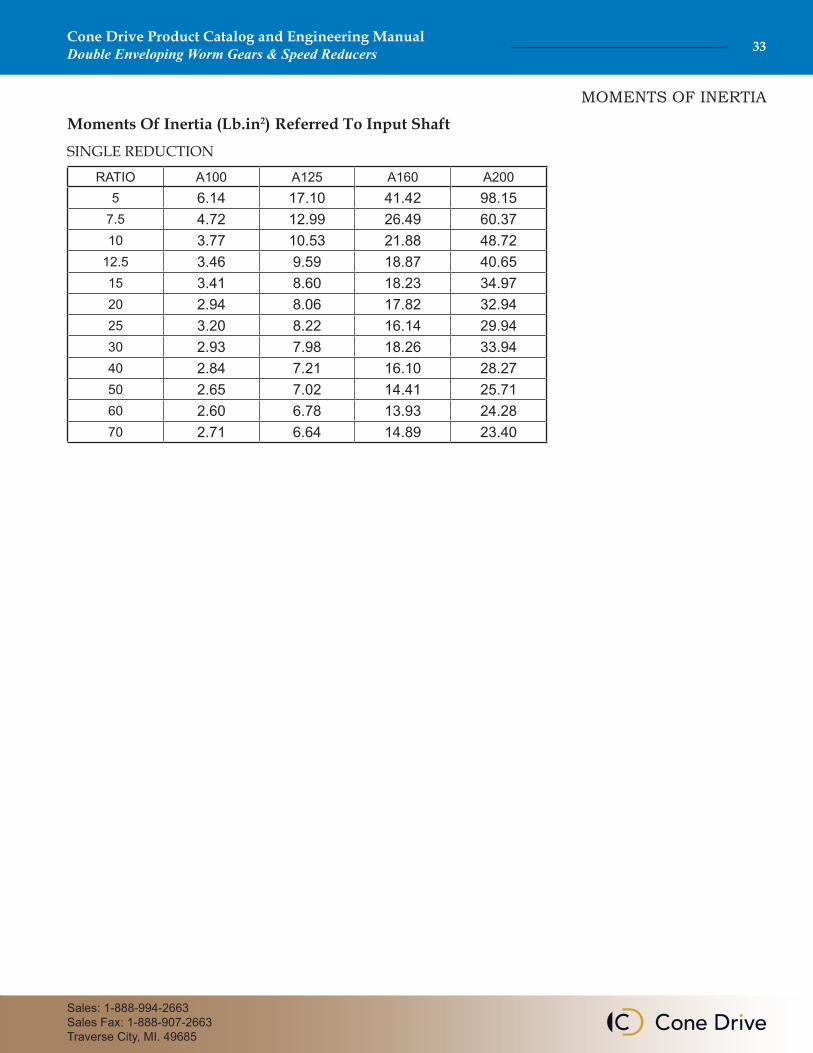
Moments Of Inertia (Lb.in2) Referred To Input ShaftSINGLE REDUCTION
RATIO A100 A125 A160 A2005 6.14 17.10 41.42 98.15
7.5 4.72 12.99 26.49 60.3710 3.77 10.53 21.88 48.72
12.5 3.46 9.59 18.87 40.6515 3.41 8.60 18.23 34.9720 2.94 8.06 17.82 32.9425 3.20 8.22 16.14 29.9430 2.93 7.98 18.26 33.9440 2.84 7.21 16.10 28.2750 2.65 7.02 14.41 25.7160 2.60 6.78 13.93 24.2870 2.71 6.64 14.89 23.40
Cone Drive Product Catalog and Engineering ManualDouble Enveloping Worm Gears & Speed Reducers34
Cone Drive reserves the right to improve or change product design and specifications without notice.
Cone Drive Product Catalog and Engineering ManualDouble Enveloping Worm Gears & Speed Reducers 35
Sales: 1-888-994-2663Sales Fax: 1-888-907-2663Traverse City, MI. 49685
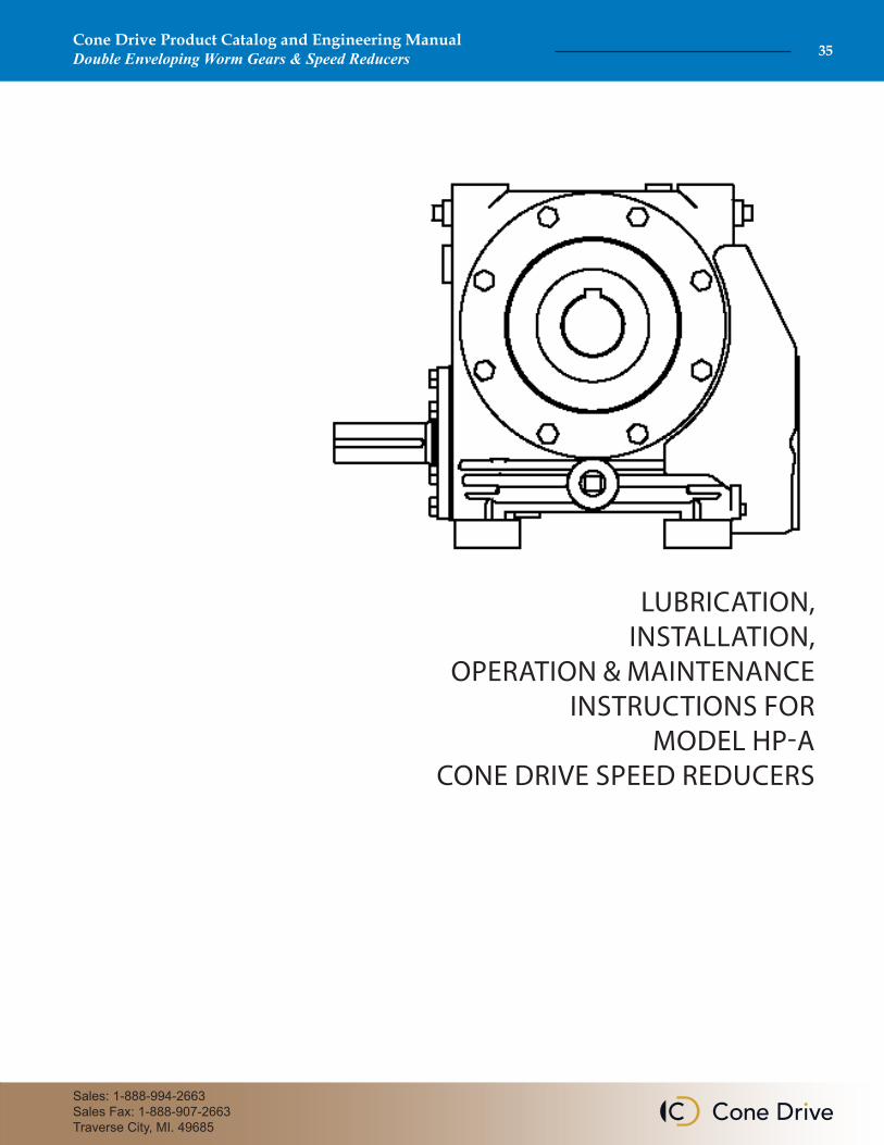
LUBRICATION, INSTALLATION,
OPERATION & MAINTENANCE INSTRUCTIONS FOR
MODEL HP-A CONE DRIVE SPEED REDUCERS
FINISH COAT PAINTING
Cone Drive double-enveloping worm gear speed reduc-ers are used throughout Industry to provide smooth and
quiet speed reduction. When properly selected, applied and maintained, they will provide optimum performance.
Cone Drive speed reducers are furnished with a prime coat of paint on exterior housing surfaces. The reducer should be painted with a finish coat to protect the hous-ing exterior, particularly if subjected to outdoor service,
periodic washdown or harsh environments. Mask all shafts, oil seals, tags, name plates, oil level stickers, breathers, gauges etc. before painting. (Painting seal lips can result in oil leakage.)
1. Do not attempt to install or operate this reducer until all of these instructions are read and thoroughly understood. If you have any questions, please contact Cone Drive.
2. The horsepower or output torque capacity of this reducer and the service factor (maximum allowable operating cycle) are stamped on the reducer nameplate. These values are not to be exceeded as overloading can result in reducer failure.
Exceeding the rating and duty cycle will void the warranty. Please contact Cone Drive with any questions regarding rating and service factors.
3. Each reducer is specifically arranged to operate at the input speed specified on the nameplate. If the input speed is not specified by the customer, it is set up for 1750 RPM and service factor 1.0. Do not operate the reducer at speeds or under service other than specified on the nameplate without contacting Cone Drive for specific instructions on oil level location and bearing settings.
4. Do not alter the reducer without approval from Cone Drive.
5. This reducer has moving mechanical components and connected electrical devices, operating under high voltage to achieve its
intended purpose. Operation and repair should only be done by qualified personnel.
6. Before servicing a speed reducer, the main electrical disconnect must be moved to and locked in the off-position. The person performing the work should post on that disconnect a warning to others not to turn on the power.
7. It is normal for the reducer to operate at a housing temperature of up to 200º F. To prevent burns, proper guards or shields must be provided by the purchaser or user to prevent personnel from touching the reducer.
8. Cone Drive products are furnished without guard covers. It is the responsibility of the purchase or user to provide guards for all exposed shafting, couplings, sprockets, sheaves, belts, chains, clutches, and any other moving parts in accordance with current local, state and federal requirements.
9. Failure to follow the instructions contained in this bulletin may result in unit failure, property damage or personal injury.
IMPORTANT: In any applications of Cone Drive Products where breakage, damage, disconnection, any other malfunction of any drive train component, or excessive wear could result in personal injury or property damage,
a fail safe device capable of stopping and holding the load in the event of such an occurrence must be incorporated after the drive train.
THE FOLLOWING INFORMATION IS FOR YOUR PROTECTION. PLEASE READ CAREFULLY.
Cone Drive Product Catalog and Engineering ManualDouble Enveloping Worm Gears & Speed Reducers36
Cone Drive reserves the right to improve or change product design and specifications without notice.
1. The speed reducer must be securely mounted to a rigid flat foundation or base plate. If necessary, shim under the reducer feet to provide a flat mounting surface.
2. Bolt the reducer to the foundation or mounting base using the largest diameter bolt that will fit through the foot holes of the reducer. Be sure to use a bolt in all available mounting feet holes. Mount the reducer using bolts to SAE Grade 8 or ISO Grade 8.8 minimum.
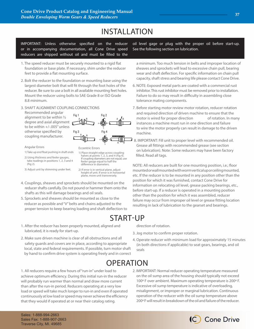
3. SHAFT ALIGNMENT COUPLING CONNECTIONS Recommended angular alignment to be within ½ degree and axial alignment to be within +/-.005” unless otherwise specified by coupling manufacturer.
4. Couplings, sheaves and sprockets should be mounted on the reducer shafts carefully. Do not pound or hammer them onto the shafts as this will damage bearings and oil seals.5. Sprockets and sheaves should be mounted as close to the reducer as possible and “V” belts and chains adjusted to the proper tension to keep bearing loading and shaft deflection to
a minimum. Too much tension in belts and improper location of sheaves and sprockets will lead to excessive chain pull, bearing wear and shaft deflection. For specific information on chain pull capacity, shaft stress and bearing life please contact Cone Drive.
6. NOTE: Exposed metal parts are coated with a commercial rust inhibitor. This rust inhibitor must be removed prior to installation. Failure to do so may result in difficulty in assembling close tolerance mating components.
7. Before starting motor review motor rotation, reducer rotation and required direction of driven machine to ensure that the motor is wired for proper direction of rotation. In many instances a machine must run in one direction and failure to wire the motor properly can result in damage to the driven machine.
8. IMPORTANT: Fill unit to proper level with recommended oil. Grease all fittings with recommended grease (see section on lubrication). Note: Some reducers may have been factory
filled. Read all tags.
NOTE: All reducers are built for one mounting position, i.e.; floor mounted or wall mounted with worm vertical up or ceiling mounted, etc. If the reducer is to be mounted in any position other than the position for which it was furnished, contact Cone Drive for information on relocating oil level, grease packing bearings, etc., before start-up. If a reducer is operated in a mounting position other than the position for which it was assembled, reducer failure may occur from improper oil level or grease fitting location resulting in lack of lubrication to the gearset and bearings.
START-UP1. After the reducer has been properly mounted, aligned and lubricated, it is ready for start-up.
2. Make sure driven machine is clear of all obstructions and all safety guards and covers are in place, according to appropriate local, state and federal requirements. If possible, turn motor shaft by hand to confirm drive system is operating freely and in correct
direction of rotation.
3. Jog motor to confirm proper rotation.
4. Operate reducer with minimum load for approximately 15 minutes (in both directions if applicable) to seat gears, bearings, and oil seals
OPERATION1. All reducers require a few hours of “run-in” under load to achieve optimum efficiency. During this initial run-in the reducer will probably run warmer than normal and draw more current than after the run-in period. Reducers operating at a very low load or speed will take much longer to run-in and even if operated continuously at low load or speed may never achieve the efficiency that they would if operated at or near their catalog rating.
2. IMPORTANT: Normal reducer operating temperature measured on the oil sump area of the housing should typically not exceed 100º F over ambient. Maximum operating temperature is 200º F. Excessive oil sump temperature is indicative of overloading, misalignment, or improper or marginal lubrication. Continuous operation of the reducer with the oil sump temperature above 200º F will result in breakdown of the oil and failure of the reducer.
Angular Errors1) Take up end float pushing in shaft ends
2) Using thickness and feeler gauges, take readings in positions 1, 2, 3 and 4 (Fig 2).
3) Adjust unit by shimming under feet.
Eccentric Errors1) Place straight edge across coupling halves at points 1, 2, 3, and 4 (Fig 4). If coupling diameters are not equal, use feeler gauge equal to half the difference in diameters.
2) If error is in vertical plane, adjust height of unit. If error is in horizontal plane, move unit transversely.
1
24
3
1
24
3
INSTALLATIONIMPORTANT: Unless otherwise specified on the reducer or in accompanying documentation, all Cone Drive speed reducers are shipped without oil and must be filled to the
oil level gage or plug with the proper oil before start-up. See the following section on lubrication.
Cone Drive Product Catalog and Engineering ManualDouble Enveloping Worm Gears & Speed Reducers 37
Sales: 1-888-994-2663Sales Fax: 1-888-907-2663Traverse City, MI. 49685
If a reducer is to be stored or shut down for more than 60 days,it should be protected from water condensation and corrosionas follows:
Any enclosed system of gearing is subject to water condensation on the inside of the reducer caused by fluctuating ambient temperatures. This condensation can cause severe rusting of the worm and bearings which could lead to premature failure of the reducer. However, this condition can be prevented by following the recommendations outlined for various storage conditions. If the reducer is furnished with a motor, follow the motor manufacturer's recommendations for motor preservation.
1. Standard Shipping Procedure - Protection for Maximum Storage Duration of 60 Days. Cone Drive speed reducers are treated inside using a rust inhibitor, the exterior is painted with one coat of primer, and all exposed shafting coated with a rust preventative prior to shipment. This procedure is intended to protect the reduc-ers during shipment and short term inside storage for a maximum period of sixty (60) days after shipment.
2. Long Term Storage (Indoors) for Periods up to One Year. 2a. Fill the reducer completely full with one of the lubricants shown on Cone Drive’s Approved List of Lubricants (23169). A copy of theis lubricant list is shipped with each unit.
2b. Rotate the worm shaft and gearshaft at least every 60 days to keep the seals from sticking to the shafts.
2c. If it is not practical to rotate the wormshaft periodically, it is recommended to purchase a spare set of oil seals to have on hand in case of seal leakage at start-up.
2d. Before putting the reducer into service, lower the oil in the reducer to the proper operating level.
3. Long Term Storage (Outdoors) for Periods Up to One Year. Proceed as in (2) with the following additions:
3a. After filling the unit with oil, plug the breather with a pipe plug and wire the breather to the unit.
3b. Paint the outside of the unit with a finish coat of paint. (Reducer from the factory is prime coated only.)
3c. Coat all exposed shafting with a long term rust preventative.
4. Extended Storage Periods Exceeding One Year. Immediately after receipt of the reducer:
4a. Apply finish paint to the exterior of the unit, excluding shafts and mounting points.
4b. Coat all exposed unpainted surfaces with a long term rust preventative.
4c. Place the unit in a vapor corrosion inhibitor (VCI) bag and seal the bag air tight.
4d. Crate the unit and cover the crate to keep out water.
4e. Purchase a spare set of oil seals to have on hand in case of leakage at start-up.
STORAGE RECOMMENDATIONS FOR CONE DRIVE SPEED REDUCERS
MAINTENANCE1. The reducer oil levels should be checked regularly and the recommended oil added as required to maintain the proper oil level.
2. Grease fittings and nilos rings are furnished when required. They should be greased with a high quality lithium base NLGI #2 or NLGI #3 bearing grease once per year, and care should be taken not to over-fill.
3. The reducer, particularly finned areas and fan covers, should be kept clean to allow maximum heat dissipation.
4. All reducers and foundation bolts should be checked for tight ness after three (3) months of service and annually thereafter.
5. If a reducer is to be repaired, contact Cone Drive for detailed instructions, drawings, parts lists, etc. If it is necessary field service is available.
6. If a reducer is to be returned, contact Cone Drive for instructions and a return material authorization (CASE) number.
OIL CHANGEIf an approved synthetic lubricant is used, it should be changed after 5000 hours of operation or once per year, whichever occurs first. See Cone Drive's Approved List of Lubricants (23169) for recommended lubricants. These change intervals are recommended for units operating under favorable conditions. Where operating conditions are severe, such a rapid rise and fall in temperature of the gear case with accompanied sweating of the inside walls and resulting formation of sludge, or where operation is in moist or dusty atmospheres, or in the presence of chemical fumes or extended running at sump temperatures in excess of 180° F, it may be necessary to change the oil at intervals of one to three months. It is recommended a sampling program be established with your lubricant manufacturer where reducers are exposed to the severe operating conditions, mentioned above.
If switching to a different type of lubricant, care should be taken
to thoroughly flush out all of the old lubricant before filling with new lubricant. Mixing of different lubricants can result in degraded performance or failure.
Cone Drive Product Catalog and Engineering ManualDouble Enveloping Worm Gears & Speed Reducers38
Cone Drive reserves the right to improve or change product design and specifications without notice.
LUBRICATION DATALubrication is very important for successful operation of Cone Drive gearsets and speed reducers. Inadequate lubrication can result in increased power consumption, added maintenance and gearset failure. Please review the following recommendations and the “Approved List of Lubricants” shipped with all Cone Drive gearsets and speed reducers. Cone Drive recommends only those lubricants listed or any lubricant which meets all the requirements of AGMA (American Gear Manufacturers Association) 9004-D94 “Lubrication of Industrial Enclosed Gear Drives” as it applies to double envel-oping worm gearing. Use of other lubricants can result in gearset failure which will not be covered under warranty. See reducers nameplate for the recommended lubricant.
TYPE OF OILRated performance of Cone Drive products is based on synthetic lu-bricants. Using a mineral oil will reduce the mechanical power and output torque ratings by 25%.
AMBIENT TEMPERATUREThe oils shown in Cone Drive's Approved List of Lubricants (23169) are for use in an ambient temperature range of approximately 15° to 125°F with the low end of the range depending on the pour point of the specific oil used. If the ambient temperature will be below or above this range please contact Cone Drive for specific recom-mendations on proper lubricant as well as proper oil seal and shim materials.
OIL SUMP TEMPERATURESThe maximum recommended oil sump temperature is 200°F. Where reducers will be used at maximum ambient and full catalog rating. Contact Cone Drive for lubrication recommendations.
SLUDGEIt is necessary that the oil be clean and free from sludge at all times to obtain long life from a gear unit. Sludge in gear units may be caused by excessive heat, from dust and dirt and other contami-nates and by the presence of moisture or chemical fumes. There-fore, every precaution should be taken to prevent water and foreign particles from entering the gear case.
OIL LEVELCone Drive reducers are furnished with a bronze colored hex head pipe plug to indicate oil level. An oil level tag is affixed to the unit near the oil level indicator. Oil level should always be checked with the unit stopped. Estimated oil capacities for standard reducers are listed in Oil Capacity for Model HP-A (25173) and are shipped with all Cone Drive gearsets and reducers.
EXTREME PRESSURE (E.P.) LUBRICANTSExtreme Pressure (E.P.) lubricants or cylinder oils with sulphur-phosphorus additives are not acceptable and should not be used in Cone Drive Speed reducers or worm gearing.
Cone Drive Product Catalog and Engineering ManualDouble Enveloping Worm Gears & Speed Reducers 39
Sales: 1-888-994-2663Sales Fax: 1-888-907-2663Traverse City, MI. 49685
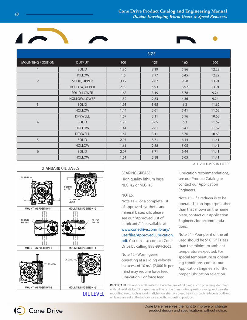
IMPORTANT: Do not overfill units. Fill to center line of oil gauge or to pipe plug identified with oil level sticker. Oil capacities will vary due to mounting positions or type of gearshaft mounting used, such as solid shaft, hollow shaft or spread bearings. Each reducer is built and oil levels are set at the factory for a specific mounting position.
BEARING GREASE:High quality lithium baseNLGI #2 or NLGI #3
NOTES:Note #1 - For a complete list of approved synthetic and mineral based oils please see our "Approved List of Lubricants" file available at www.conedrive.com/library/userfiles/ApprovedLubrication.pdf. You can also contact Cone Drive by calling 888-994-2663.
Note #2 - Worm gears operating at a sliding velocity in excess of 10 m/s (2,000 ft. per min.) may require force feed lubrication. For force feed
lubrication recommendations, see our Product Catalog or contact our Application Engineers.
Note #3 - If a reducer is to be operated at an input rpm other than that shown on the name plate, contact our Application Engineers for recommenda-tions.
Note #4 - Pour point of the oil used should be 5° C (9° F) less than the minimum ambient temperature expected. For special temperature or operat-ing conditions, contact our Application Engineers for the proper lubrication selection.
SIZE
MOUNTING POSITION OUTPUT 100 125 160 200
1 SOLID 1.86 3.19 5.86 12.22
HOLLOW 1.6 2.77 5.45 12.22
2 SOLID, UPPER 3.12 7.07 9.58 13.91
HOLLOW, UPPER 2.59 5.93 6.92 13.91
SOLID, LOWER 1.68 3.19 5.78 9.24
HOLLOW, LOWER 1.52 2.83 4.36 9.24
3 SOLID 1.95 3.65 6.3 11.62
HOLLOW 1.44 2.61 5.41 11.62
DRYWELL 1.67 3.11 5.76 10.68
4 SOLID 1.95 3.65 6.3 11.62
HOLLOW 1.44 2.61 5.41 11.62
DRYWELL 1.67 3.11 5.76 10.68
5 SOLID 2.07 3.71 6.44 11.41
HOLLOW 1.61 2.88 5.05 11.41
6 SOLID 2.07 3.71 6.44 11.41
HOLLOW 1.61 2.88 5.05 11.41
ALL VOLUMES IN LITERS
Cone Drive Product Catalog and Engineering ManualDouble Enveloping Worm Gears & Speed Reducers40
Cone Drive reserves the right to improve or change product design and specifications without notice.
Cone Drive Product Catalog and Engineering ManualDouble Enveloping Worm Gears & Speed Reducers 41
Sales: 1-888-994-2663Sales Fax: 1-888-907-2663Traverse City, MI. 49685
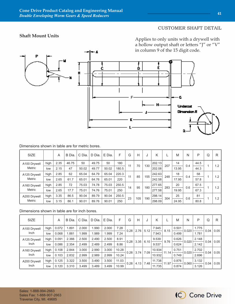
CUSTOMER SHAFT DETAIL
Shaft Mount UnitsApplies to only units with a drywell with a hollow output shaft or letters “J” or “V” in column 9 of the 15 digit code.
SIZE A B Dia. C Dia. D Dia. E Dia. F G H J K L M N P Q R
A100 Drywell Metric
high 2.35 46.75 50 49.75 50 18011 70 130
202.13207
140.4
44.51 1.2
low 2.15 47 50.02 49.77 50.02 180.5 202.08 13.95 44.3
A125 Drywell Metric
high 2.85 62 65.04 64.79 65.04 220.311 85 155
242.63248
180.4
581 1.2
low 2.65 61.7 65.01 64.76 65.01 220 242.58 17.95 57.8
A160 Drywell Metric
high 2.85 72 75.03 74.78 75.03 250.514 95 180
277.65283
200.6
67.51 1.2
low 2.65 17.7 75.01 74.76 75.01 250 277.58 19.95 67.3
A200 Drywell Metric
high 3.35 86.5 90.04 89.79 90.04 250.523 105 190
298.14304
250.6
811 1.2
low 3.15 86.1 90.01 89.76 90.01 250 298.09 24.95 80.8
SIZE A B Dia. C Dia. D Dia. E Dia. F G H J K L M N P Q R
A100 Drywell Inch
high 0.072 1.891 2.000 1.990 2.000 7.280.28 2.76 5.12
7.9458.15
0.5010.020
1.7750.04 0.05
low 0.068 1.881 1.999 1.989 1.999 7.24 7.943 0.499 1.781
A125 Drywell Inch
high 0.091 2.366 2.500 2.490 2.500 8.910.28 3.35 6.10
9.5399.76
0.6260.020
2.1480.04 0.05
low 0.086 2.354 2.499 2.489 2.499 8.86 9.537 0.624 2.142
A160 Drywell Inch
high 0.108 2.844 3.000 2.990 3.000 10.280.28 3.74 7.09
10.93411.14
0.7510.020
2.7020.04 0.05
low 0.103 2.832 2.999 2.989 2.999 10.24 10.932 0.749 2.696
A200 Drywell Inch
high 0.125 3.322 3.500 3.490 3.500 11.030.28 4.13 7.48
11.73811.97
0.8760.060
3.1320.04 0.05
low 0.120 3.310 3.499 3.489 3.499 10.99 11.735 0.874 3.126
Dimensions shown in table are for metric bores.
Dimensions shown in table are for inch bores.

Cone Drive Product Catalog and Engineering ManualDouble Enveloping Worm Gears & Speed Reducers42
Cone Drive reserves the right to improve or change product design and specifications without notice.
NOTES
Cone Drive Product Catalog and Engineering ManualDouble Enveloping Worm Gears & Speed Reducers 43
Sales: 1-888-994-2663Sales Fax: 1-888-907-2663Traverse City, MI. 49685
NOTES

Cone Drive Europe1 Redwood Crescent, Peel Park
East Kilbride G74 5PAUK
Cone Drive Operations, Inc.240 East 12th Street
Traverse City, Michigan 49684USA
H-FangA Cone Drive Brand
No. 20 Yungu RoadChangshou
Zhouzhuang Town, JiangyinJiangsu PR China 214424
T +1 888 994 2663E [email protected] www.conedrive.com
GLOBAL LOCATIONSNORTH AMERICA | CHINA | EUROPE