Embed Size (px)
Citation preview
SeriesCircuits
Lecture No.4Mehran U.E.TKhairpur
SERIES CIRCUITS
Engr. S.H.Qazi
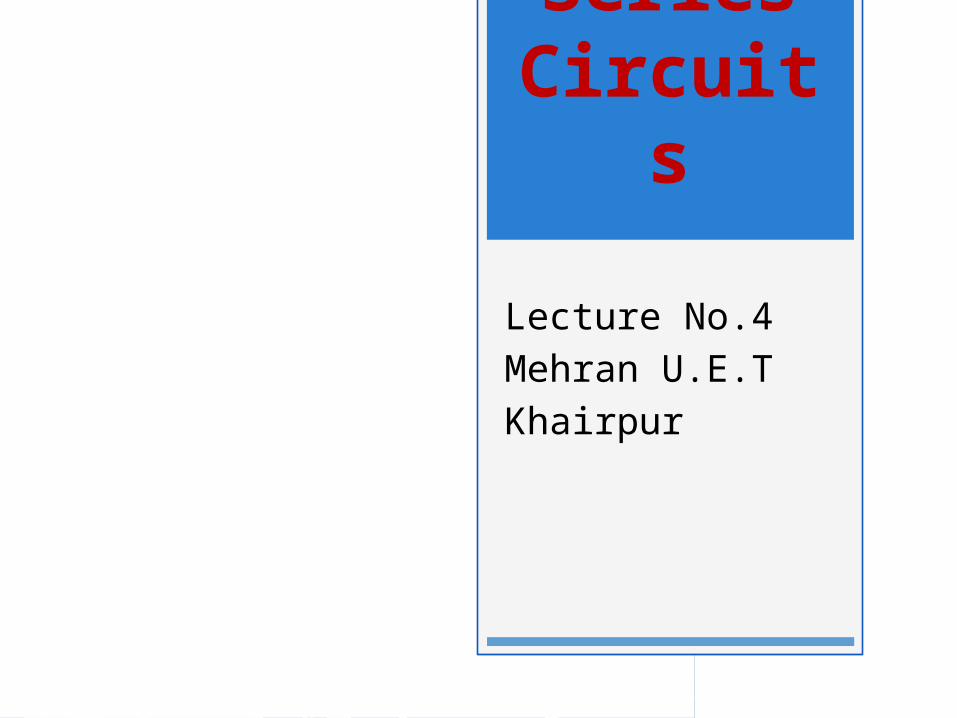
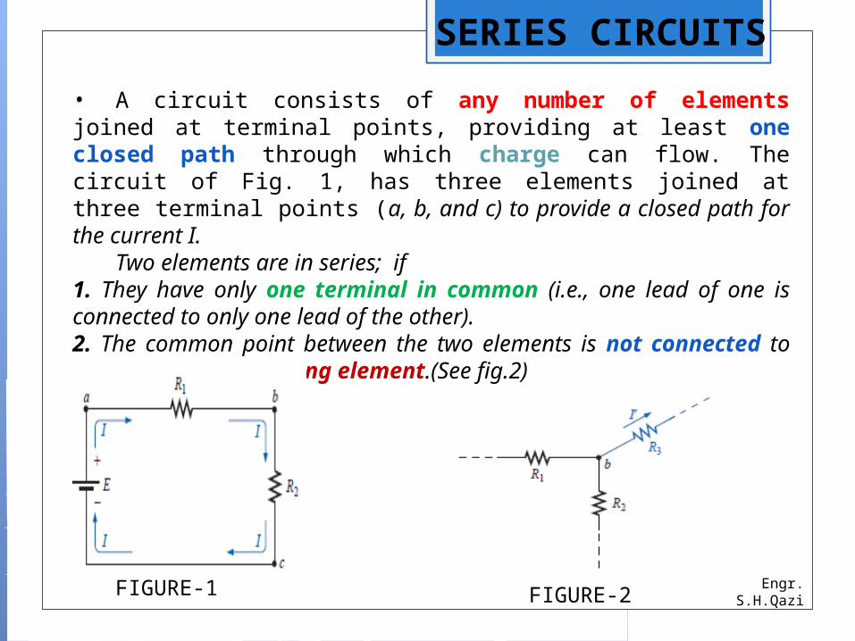
• A circuit consists of any number of elements joined at terminal points, providing at least one closed path through which charge can flow. The circuit of Fig. 1, has three elements joined at three terminal points (a, b, and c) to provide a closed path for the current I. Two elements are in series; if1. They have only one terminal in common (i.e., one lead of one is connected to only one lead of the other).2. The common point between the two elements is not connected to another current-carrying element.(See fig.2)
FIGURE-1 FIGURE-2
Engr. S.H.Qazi
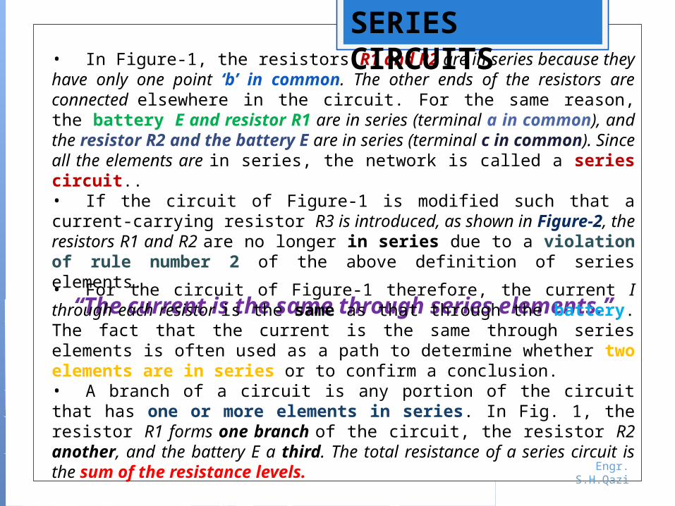
• In Figure-1, the resistors R1 and R2 are in series because they have only one point ‘b’ in common. The other ends of the resistors are connected elsewhere in the circuit. For the same reason, the battery E and resistor R1 are in series (terminal a in common), and the resistor R2 and the battery E are in series (terminal c in common). Since all the elements are in series, the network is called a series circuit..• If the circuit of Figure-1 is modified such that a current-carrying resistor R3 is introduced, as shown in Figure-2, the resistors R1 and R2 are no longer in series due to a violation of rule number 2 of the above definition of series elements.
“The current is the same through series elements.”
• For the circuit of Figure-1 therefore, the current I through each resistor is the same as that through the battery. The fact that the current is the same through series elements is often used as a path to determine whether two elements are in series or to confirm a conclusion.• A branch of a circuit is any portion of the circuit that has one or more elements in series. In Fig. 1, the resistor R1 forms one branch of the circuit, the resistor R2 another, and the battery E a third. The total resistance of a series circuit is the sum of the resistance levels.
SERIES CIRCUITS
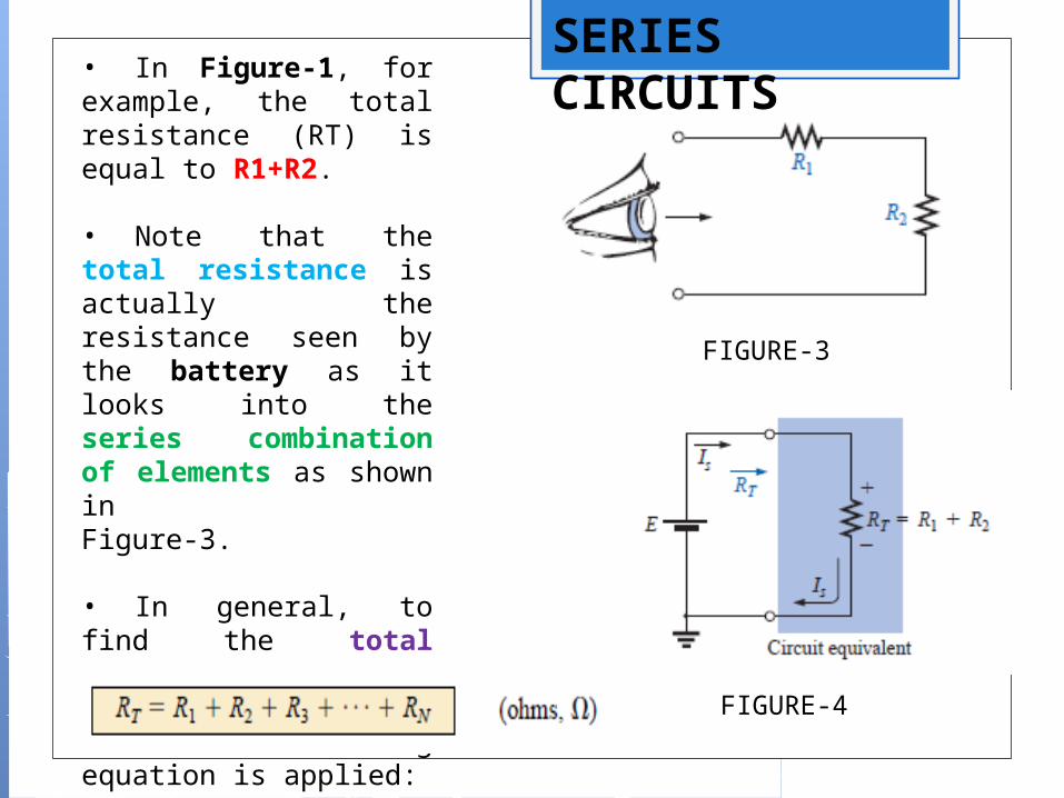
• In Figure-1, for example, the total resistance (RT) is equal to R1+R2.
• Note that the total resistance is actually the resistance seen by the battery as it looks into the series combination of elements as shown inFigure-3.
• In general, to find the total resistance of N resistors in series, the following equation is applied:
FIGURE-3
FIGURE-4
SERIES CIRCUITS
Engr. S.H.Qazi
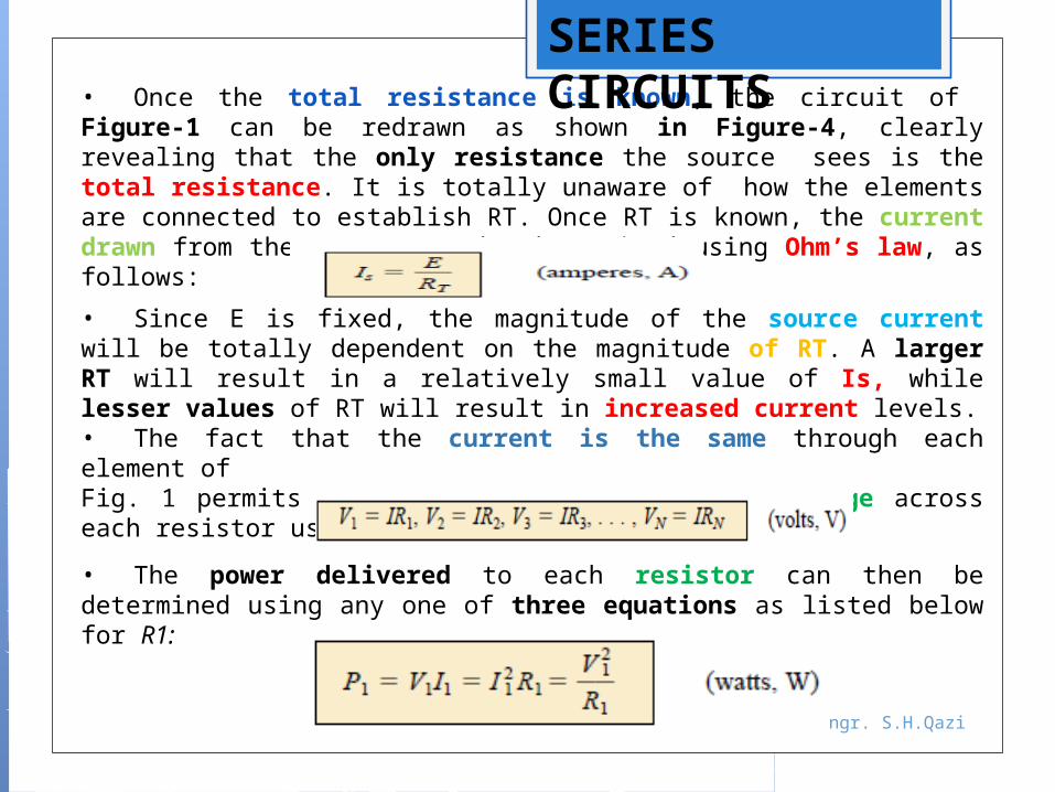
• Once the total resistance is known, the circuit of Figure-1 can be redrawn as shown in Figure-4, clearly revealing that the only resistance the source sees is the total resistance. It is totally unaware of how the elements are connected to establish RT. Once RT is known, the current drawn from the source can be determined using Ohm’s law, as follows:
• Since E is fixed, the magnitude of the source current will be totally dependent on the magnitude of RT. A larger RT will result in a relatively small value of Is, while lesser values of RT will result in increased current levels.• The fact that the current is the same through each element of Fig. 1 permits a direct calculation of the voltage across each resistor using Ohm’s law; that is,
• The power delivered to each resistor can then be determined using any one of three equations as listed below for R1:
SERIES CIRCUITS
Engr. S.H.Qazi
SERIES CIRCUITS
Voltage Divider Rule
Engr. S.H.Qazi
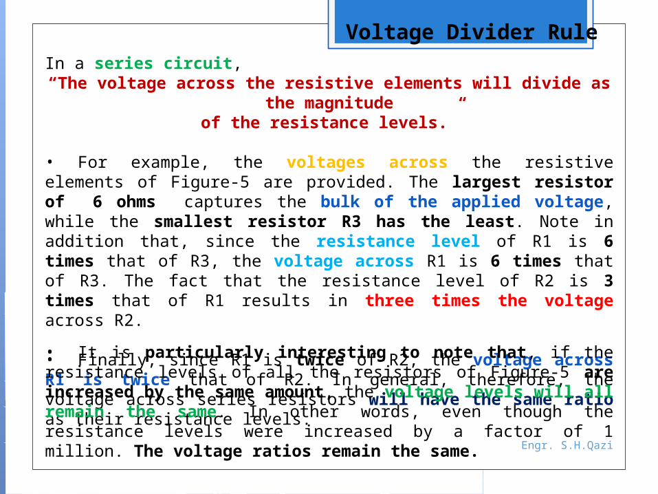
In a series circuit,“The voltage across the resistive elements will divide as the
magnitudeof the resistance levels.”
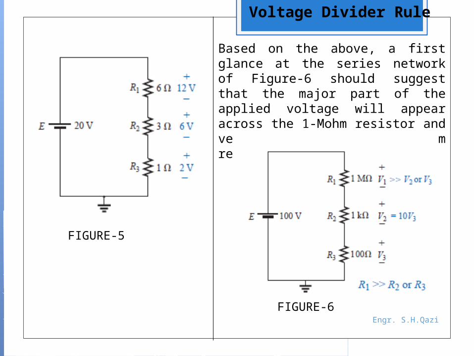
• For example, the voltages across the resistive elements of Figure-5 are provided. The largest resistor of 6 ohms captures the bulk of the applied voltage, while the smallest resistor R3 has the least. Note in addition that, since the resistance level of R1 is 6 times that of R3, the voltage across R1 is 6 times that of R3. The fact that the resistance level of R2 is 3 times that of R1 results in three times the voltage across R2.
• Finally, since R1 is twice of R2, the voltage across R1 is twice that of R2. In general, therefore, the voltage across series resistors will have the same ratio as their resistance levels.• It is particularly interesting to note that, if the resistance levels of all the resistors of Figure-5 are increased by the same amount, the voltage levels will all remain the same. In other words, even though the resistance levels were increased by a factor of 1 million. The voltage ratios remain the same.
Engr. S.H.Qazi
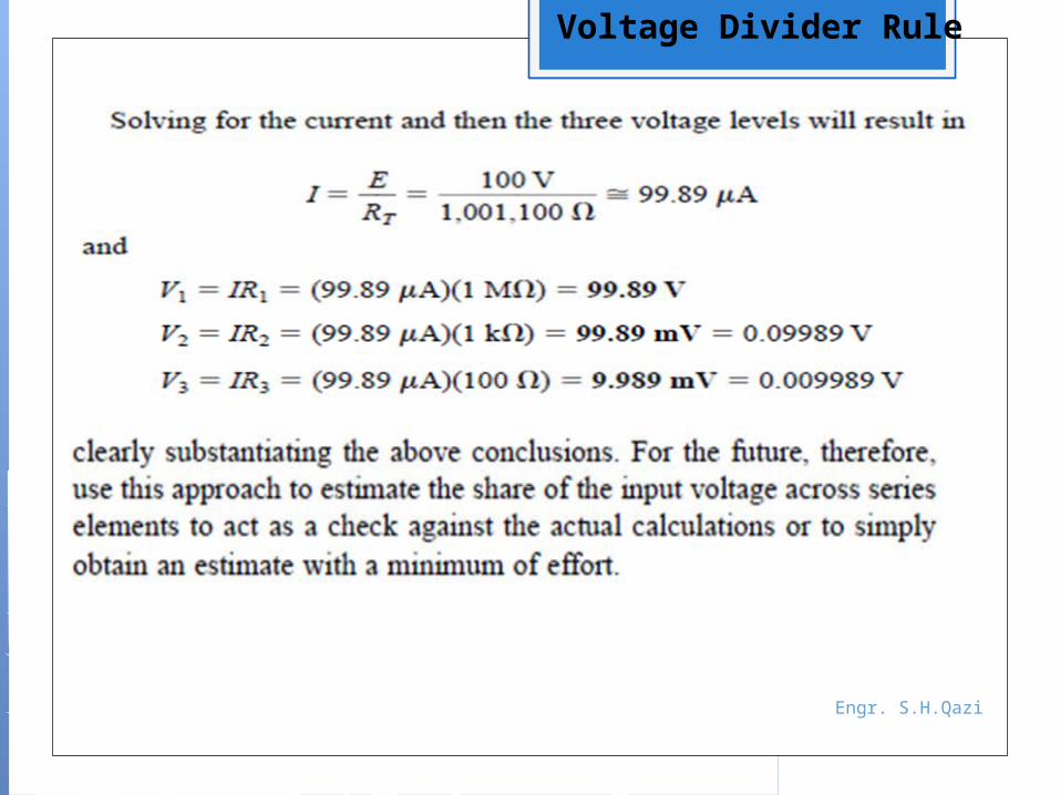
Based on the above, a first glance at the series network of Figure-6 should suggest that the major part of the applied voltage will appear across the 1-Mohm resistor and very little across the 100 ohm resistor.
FIGURE-5
FIGURE-6
Voltage Divider Rule
Engr. S.H.Qazi
Voltage Divider Rule
Engr. S.H.Qazi
FIGURE-7
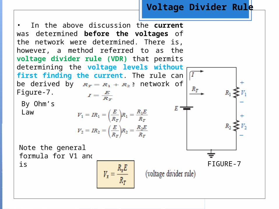
• In the above discussion the current was determined before the voltages of the network were determined. There is, however, a method referred to as the voltage divider rule (VDR) that permits determining the voltage levels without first finding the current. The rule can be derived by analyzing the network of Figure-7.
By Ohm’s Law
Note the general formula for V1 and V2 is
Voltage Divider Rule
Engr. S.H.Qazi
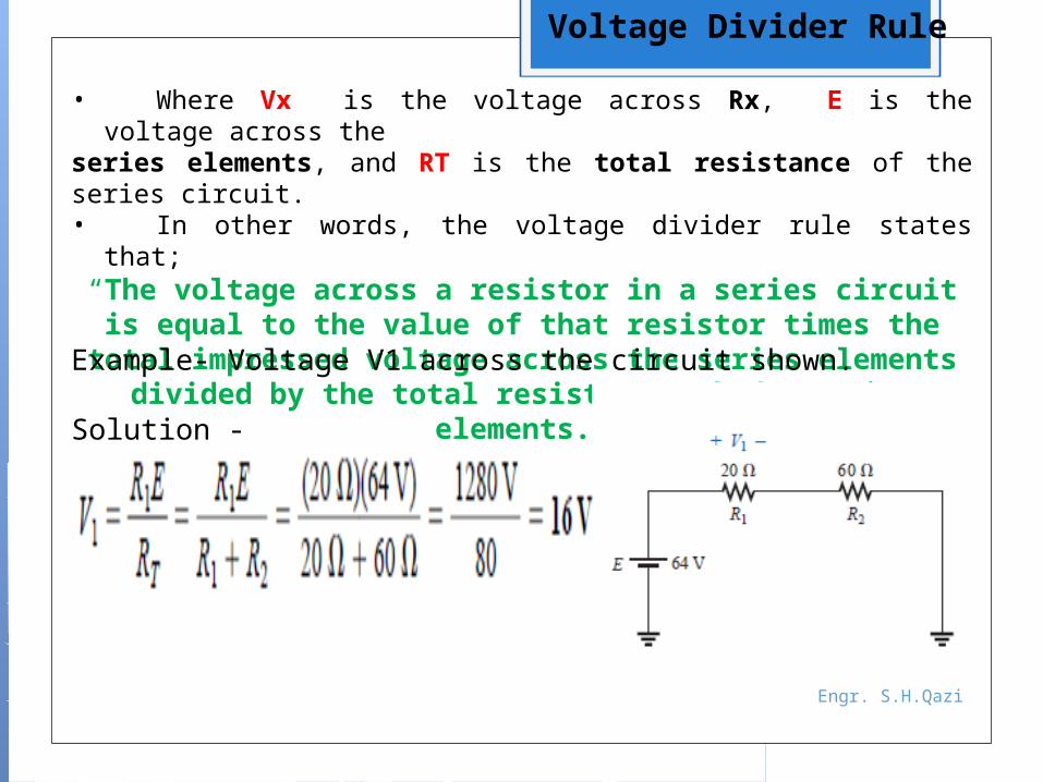
• Where Vx is the voltage across Rx, E is the voltage across the
series elements, and RT is the total resistance of the series circuit.• In other words, the voltage divider rule states that;
“The voltage across a resistor in a series circuit is equal to the value of that resistor times the total
impressed voltage across the series elements divided by the total resistance of the series elements.”Example- Voltage V1 across the circuit shown.
Solution -
Voltage Divider Rule
Engr. S.H.Qazi
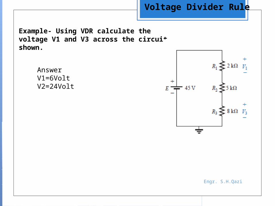
Example- Using VDR calculate the voltage V1 and V3 across the circuit shown.
Answer V1=6VoltV2=24Volt
Voltage Divider Rule
Engr. S.H.Qazi
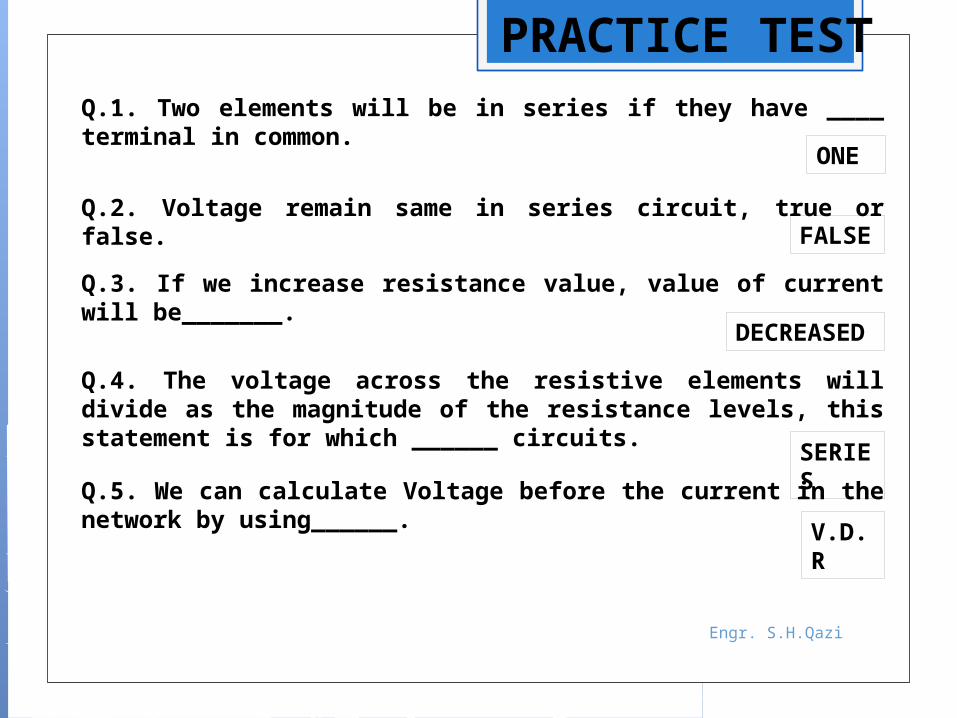
PRACTICE TESTQ.1. Two elements will be in series if they have ____ terminal in common.
ONE
Q.2. Voltage remain same in series circuit, true or false. FALSE
Q.3. If we increase resistance value, value of current will be_______.
DECREASED
Q.4. The voltage across the resistive elements will divide as the magnitude of the resistance levels, this statement is for which ______ circuits.
SERIESQ.5. We can calculate Voltage before the current in the
network by using______. V.D.R