Embed Size (px)
Citation preview
A56
Cont
acto
rs
A
visit www.sprecherschuh.com/ecatalog for the most up to date information SSNA2012
CA7
Discount Schedule R
Upda
ted
03-1
4-13
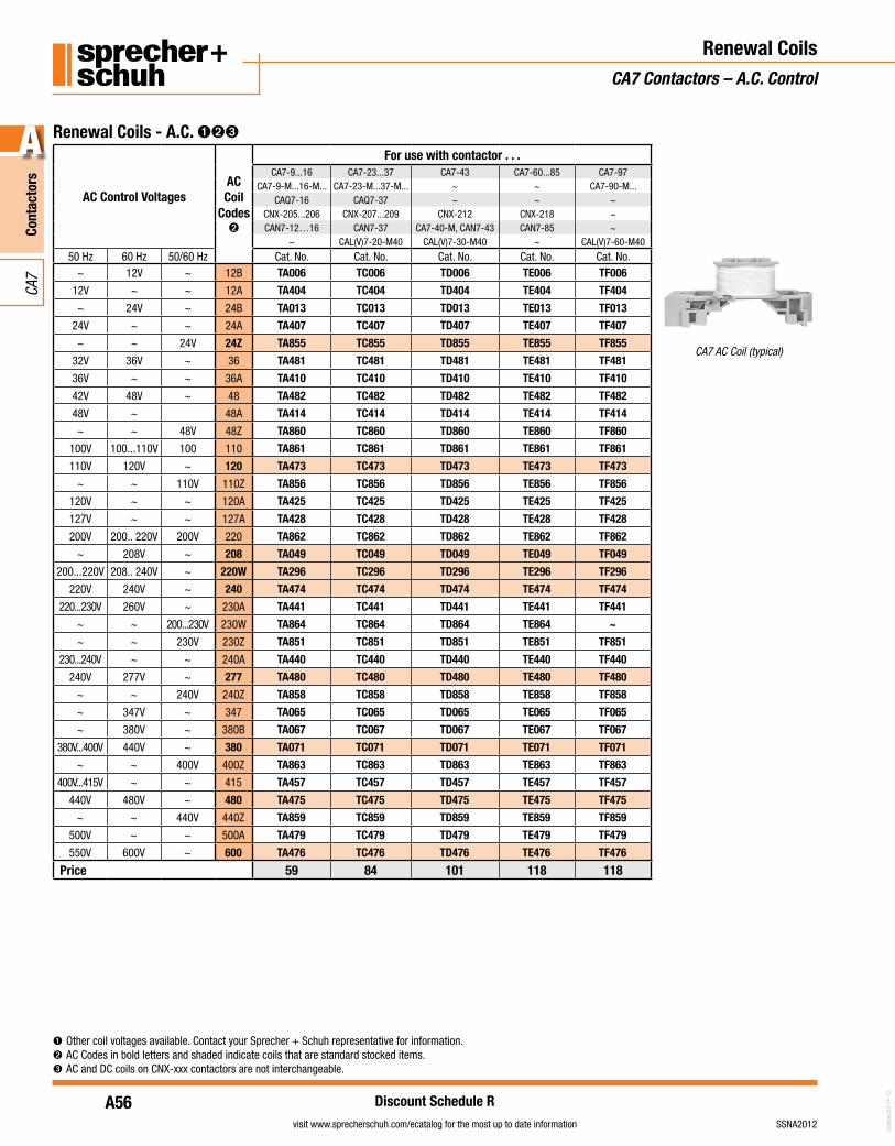
Renewal CoilsCA7 Contactors – A.C. Control
CA7 AC Coil (typical)
➊ Other coil voltages available. Contact your Sprecher + Schuh representative for information.➋ AC Codes in bold letters and shaded indicate coils that are standard stocked items.➌ AC and DC coils on CNX-xxx contactors are not interchangeable.
Renewal Coils - A.C. ➊➋➌
AC Control VoltagesACCoil
Codes➋
For use with contactor . . .CA7-9...16 CA7-23...37 CA7-43 CA7-60...85 CA7-97
CA7-9-M...16-M... CA7-23-M...37-M... ~ ~ CA7-90-M...CAQ7-16 CAQ7-37 ~ ~ ~
CNX-205...206 CNX-207...209 CNX-212 CNX-218 ~CAN7-12…16 CAN7-37 CA7-40-M, CAN7-43 CAN7-85 ~
~ CAL(V)7-20-M40 CAL(V)7-30-M40 ~ CAL(V)7-60-M40
50 Hz 60 Hz 50/60 Hz Cat. No. Cat. No. Cat. No. Cat. No. Cat. No.~ 12V ~ 12B TA006 TC006 TD006 TE006 TF006
12V ~ ~ 12A TA404 TC404 TD404 TE404 TF404
~ 24V ~ 24B TA013 TC013 TD013 TE013 TF013
24V ~ ~ 24A TA407 TC407 TD407 TE407 TF407
~ ~ 24V 24Z TA855 TC855 TD855 TE855 TF855
32V 36V ~ 36 TA481 TC481 TD481 TE481 TF481
36V ~ ~ 36A TA410 TC410 TD410 TE410 TF410
42V 48V ~ 48 TA482 TC482 TD482 TE482 TF482
48V ~ 48A TA414 TC414 TD414 TE414 TF414
~ ~ 48V 48Z TA860 TC860 TD860 TE860 TF860
100V 100...110V 100 110 TA861 TC861 TD861 TE861 TF861
110V 120V ~ 120 TA473 TC473 TD473 TE473 TF473
~ ~ 110V 110Z TA856 TC856 TD856 TE856 TF856
120V ~ ~ 120A TA425 TC425 TD425 TE425 TF425
127V ~ ~ 127A TA428 TC428 TD428 TE428 TF428
200V 200.. 220V 200V 220 TA862 TC862 TD862 TE862 TF862
~ 208V ~ 208 TA049 TC049 TD049 TE049 TF049
200...220V 208.. 240V ~ 220W TA296 TC296 TD296 TE296 TF296
220V 240V ~ 240 TA474 TC474 TD474 TE474 TF474
220...230V 260V ~ 230A TA441 TC441 TD441 TE441 TF441
~ ~ 200...230V 230W TA864 TC864 TD864 TE864 ~
~ ~ 230V 230Z TA851 TC851 TD851 TE851 TF851
230...240V ~ ~ 240A TA440 TC440 TD440 TE440 TF440
240V 277V ~ 277 TA480 TC480 TD480 TE480 TF480
~ ~ 240V 240Z TA858 TC858 TD858 TE858 TF858
~ 347V ~ 347 TA065 TC065 TD065 TE065 TF065
~ 380V ~ 380B TA067 TC067 TD067 TE067 TF067
380V...400V 440V ~ 380 TA071 TC071 TD071 TE071 TF071
~ ~ 400V 400Z TA863 TC863 TD863 TE863 TF863
400V...415V ~ ~ 415 TA457 TC457 TD457 TE457 TF457
440V 480V ~ 480 TA475 TC475 TD475 TE475 TF475
~ ~ 440V 440Z TA859 TC859 TD859 TE859 TF859
500V ~ ~ 500A TA479 TC479 TD479 TE479 TF479
550V 600V ~ 600 TA476 TC476 TD476 TE476 TF476
Price 59 84 101 118 118
A57
Cont
acto
rs
A
visit www.sprecherschuh.com/ecatalog for the most up to date informationSSNA2012
CA7
Discount Schedule R
Upda
ted
04-0
8-13
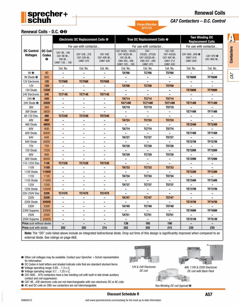
Renewal CoilsCA7 Contactors – D.C. Control
➊ Other coil voltages may be available. Contact your Sprecher + Schuh representative for information.
➋ DC Codes in bold letters and shaded indicate coils that are standard stocked items.➌ Voltage operating range: 0.65…1.3 x Us.➍ Voltage operating range: 0.7…1.25 x Us.➎ CA7-60D…97D contactors have a two winding coil with built-in late break auxiliary
contact and coil suppression.➏ CA7-9E...43E electronic coils are not interchangeable with non-electronic DC or AC coils➐ AC and DC coils on CNX-xxx contactors are not interchangeable.
48V, 110V & 220V Electronic DC coil with Back Pack
Two Winding DC coil (typical) ➎
Renewal Coils - D.C. ➊➋
DC Control Voltages
DC CoilCodes➋
Electronic DC Replacement Coils ➏ True DC Replacement Coils ➐Two Winding DC
Replacement CoilsFor use with contactor... For use with contactor... For use with contactor...
CA7-9E...16ECA7-9E-M...
16E-M...CAN7-12E…16E
CA7-23E...37ECA7-23E-M...
CAN7-37E
CA7-43ECA7-40E-M...
CAN7-43E
CA7-9C(D)...16C(D)CA7-9C(D)-M...
16C (D)-M...CNX-205...206
CAN7-12C…16C
CA7-23C(D)...37C(D)CA7-23C(D)-M...CNX-207...209
CAN7-37C
CA7-43CCA7-43C(D)
CA7-40C-M...CNX7-212CAN7-43C
CA7-60D...85D ➎CNX7-218CAN7-85D
CA7-97D ➎CA7-90D-M...
Cat. No. Cat. No. Cat. No. Cat. No. Cat. No. Cat. No. Cat. No. Cat. No.
9V ➌ 9D ~ ~ ~ TA766 TC766 TD766 ~ ~9V Diode ➌ 9DD ~ ~ ~ ~ ~ ~ TE766M TF766M
12V Electronic 12E TC708E TC708E TD708E ~ ~ ~ ~ ~12V 12D ~ ~ ~ TA708 TC708 TD708 ~ ~
12V Diode 12DD ~ ~ ~ ~ ~ ~ TE708M TF708M24V Electronic 24E TC714E TC714E TD714E ~ ~ ~ ~ ~
24V ❹ 24D ~ ~ ~ TA714 TC714 TD714 ~ ~24V Diode ➍ 24DD ~ ~ ~ TA714M TC714M TD714M TE714M TF714M
36V 36D ~ ~ ~ TA719 TC719 TD719 ~ ~36V Diode 36DD ~ ~ ~ ~ ~ ~ TE719M TF719M
48-72V Elec 48E TC724E TC724E TD724E ~ ~ ~ ~ ~48V 48D ~ ~ ~ TA724 TC724 TD724 ~ ~
48V Diode 48DD ~ ~ ~ ~ ~ ~ TE724M TF724M60V 60D ~ ~ ~ TA774 TC774 TD774 ~ ~
60V Diode 60DD ~ ~ ~ ~ ~ ~ TE774M TF774M64V 64D ~ ~ ~ TA727 TC727 TD727 ~ ~
64V Diode 64DD ~ ~ ~ ~ ~ ~ TE727M TF727M72V 72D ~ ~ ~ TA728 TC728 TD728 ~ ~
72V Diode 72DD ~ ~ ~ ~ ~ ~ TE728M TF728M80V 80D ~ ~ ~ TA729 TC729 TD729 ~ ~
80V Diode 80DD ~ ~ ~ ~ ~ ~ TE729M TF729M110-125V Elec 110E TC733E TC733E TD733E ~ ~ ~ ~ ~
110V 110D ~ ~ ~ TA733 TC733 TD733 ~ ~110V Diode 110DD ~ ~ ~ ~ ~ ~ TE733M TF733M
115V 115D ~ ~ ~ TA734 TC734 TD734 ~ ~115V Diode 115DD ~ ~ ~ ~ ~ ~ TE734M TF734M
125V 125D ~ ~ ~ TA737 TC737 TD737 ~ ~125V Diode 125DD ~ ~ ~ ~ ~ ~ TE737M TF737M
220-250V Elec 220E TC747E TC747E TD747E ~ ~ ~ ~ ~220V 220D ~ ~ ~ TA747 TC747 TD747 ~ ~
220V Diode 220DD ~ ~ ~ ~ ~ ~ TE747M TF747M230V 230D ~ ~ ~ TA749 TC749 TD749 ~ ~
230V Suppres. 230DS ~ ~ ~ ~ ~ ~ TE749M TF749M250V 250D ~ ~ ~ TA751 TC751 TD751 ~ ~
250V Suppres. 250DS ~ ~ ~ ~ ~ ~ TE751M TF751MPrice (coil without diode) ~ ~ ~ 138 165 190 ~ ~Price (coil with diode) 202 202 215 202 202 215 235 235
Note: The “DD” coils listed above include an integrated bidirectional diode. Drop out time of this design is significantly improved when compared to an external diode. See ratings on page A68.
12V & 24V Electronic DC coil
Prices Effective 5/11/13
A58
Cont
acto
rs
A
visit www.sprecherschuh.com/ecatalog for the most up to date information SSNA2012
CA7
Discount Schedule A-1
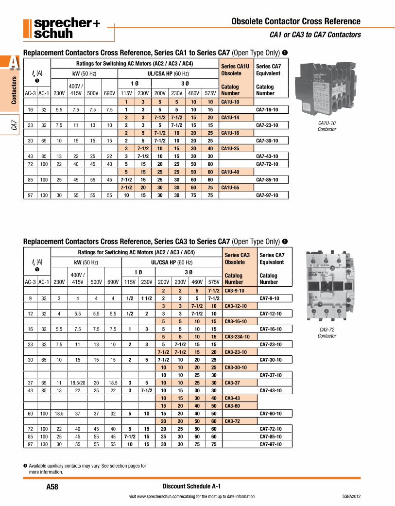
Obsolete Contactor Cross ReferenceCA1 or CA3 to CA7 Contactors
Replacement Contactors Cross Reference, Series CA3 to Series CA7 (Open Type Only) ➊
Ie [A]➊
Ratings for Switching AC Motors (AC2 / AC3 / AC4) Series CA3Obsolete
Catalog Number
Series CA7Equivalent
Catalog Number
kW (50 Hz) UL/CSA HP (60 Hz)
230V400V /415V 500V 690V
1 Ø 3 Ø
AC-3 AC-1 115V 230V 200V 230V 460V 575V
2 2 5 7-1/2 CA3-9-10
9 32 3 4 4 4 1/2 1 1/2 2 2 5 7-1/2 CA7-9-10
3 3 7-1/2 10 CA3-12-10
12 32 4 5.5 5.5 5.5 1/2 2 3 3 7-1/2 10 CA7-12-10
5 5 10 15 CA3-16-10
16 32 5.5 7.5 7.5 7.5 1 3 5 5 10 15 CA7-16-10
5 5 10 15 CA3-23A-10
23 32 7.5 11 13 10 2 3 5 7-1/2 15 15 CA7-23-10
7-1/2 7-1/2 15 20 CA3-23-10
30 65 10 15 15 15 2 5 7-1/2 10 20 25 CA7-30-10
10 10 20 25 CA3-30-10
10 10 25 30 CA7-37-10
37 65 11 18.5/20 20 18.5 3 5 10 10 25 30 CA3-37
43 85 13 22 25 22 3 7-1/2 10 15 30 30 CA7-43-10
10 15 30 40 CA3-43
15 20 40 50 CA3-60
60 100 18.5 37 37 32 5 10 15 20 40 50 CA7-60-10
20 20 50 60 CA3-72
72 100 22 40 45 40 5 15 20 25 50 60 CA7-72-10
85 100 25 45 55 45 7-1/2 15 25 30 60 60 CA7-85-10
97 130 30 55 55 55 10 15 30 30 75 75 CA7-97-10
CA3-72Contactor
Replacement Contactors Cross Reference, Series CA1 to Series CA7 (Open Type Only) ➊
Ie [A]➊
Ratings for Switching AC Motors (AC2 / AC3 / AC4) Series CA1UObsolete
Catalog Number
Series CA7Equivalent
Catalog Number
kW (50 Hz) UL/CSA HP (60 Hz)
230V400V /415V 500V 690V
1 Ø 3 Ø
AC-3 AC-1 115V 230V 200V 230V 460V 575V
1 3 5 5 10 10 CA1U-10
16 32 5.5 7.5 7.5 7.5 1 3 5 5 10 15 CA7-16-10
2 3 7-1/2 7-1/2 15 20 CA1U-14
23 32 7.5 11 13 10 2 3 5 7-1/2 15 15 CA7-23-10
2 5 7-1/2 10 20 25 CA1U-16
30 65 10 15 15 15 2 5 7-1/2 10 20 25 CA7-30-10
3 7-1/2 10 15 30 40 CA1U-25
43 85 13 22 25 22 3 7-1/2 10 15 30 30 CA7-43-10
72 100 22 40 45 40 5 15 20 25 50 60 CA7-72-10
5 15 25 25 50 60 CA1U-40
85 100 25 45 55 45 7-1/2 15 25 30 60 60 CA7-85-10
7-1/2 20 30 30 60 75 CA1U-55
97 130 30 55 55 55 10 15 30 30 75 75 CA7-97-10
CA1U-10Contactor
➊ Available auxiliary contacts may vary. See selection pages for more information.
A59
Cont
acto
rs
A
visit www.sprecherschuh.com/ecatalog for the most up to date informationSSNA2012
CA7
Discount Schedule A-1
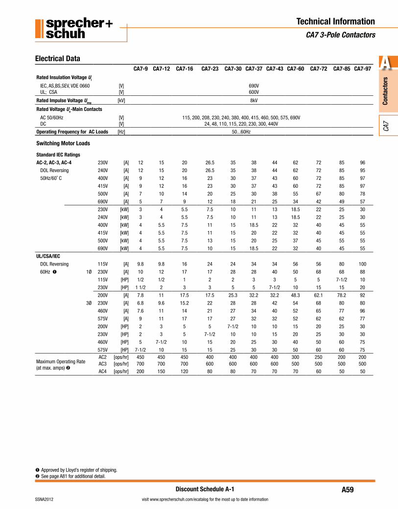
Technical InformationCA7 3-Pole Contactors
Electrical DataCA7-9 CA7-12 CA7-16 CA7-23 CA7-30 CA7-37 CA7-43 CA7-60 CA7-72 CA7-85 CA7-97
Rated Insulation Voltage Ui
IEC, AS,BS,SEV, VDE 0660 UL; CSA
[V][V]
690V600V
Rated Impulse Voltage Uimp [kV] 8kV
Rated Voltage Ue-Main Contacts
AC 50/60HzDC
[V][V]
115, 200, 208, 230, 240, 380, 400, 415, 460, 500, 575, 690V24, 48, 110, 115, 220, 230, 300, 440V
Operating Frequency for AC Loads [Hz] 50...60Hz
Switching Motor Loads
Standard IEC Ratings
AC-2, AC-3, AC-4 230V [A] 12 15 20 26.5 35 38 44 62 72 85 96
DOL Reversing 240V [A] 12 15 20 26.5 35 38 44 62 72 85 95
50Hz/60˚ C 400V [A] 9 12 16 23 30 37 43 60 72 85 97
415V [A] 9 12 16 23 30 37 43 60 72 85 97
500V [A] 7 10 14 20 25 30 38 55 67 80 78
690V [A] 5 7 9 12 18 21 25 34 42 49 57
230V [kW] 3 4 5.5 7.5 10 11 13 18.5 22 25 30
240V [kW] 3 4 5.5 7.5 10 11 13 18.5 22 25 30
400V [kW] 4 5.5 7.5 11 15 18.5 22 32 40 45 55
415V [kW] 4 5.5 7.5 11 15 20 22 32 40 45 55
500V [kW] 4 5.5 7.5 13 15 20 25 37 45 55 55
690V [kW] 4 5.5 7.5 10 15 18.5 22 32 40 45 55
UL/CSA/IEC
DOL Reversing 115V [A] 9.8 9.8 16 24 24 34 34 56 56 80 100
60Hz ➊ 1Ø 230V [A] 10 12 17 17 28 28 40 50 68 68 88
115V [HP] 1/2 1/2 1 2 2 3 3 5 5 7-1/2 10
230V [HP] 1 1/2 2 3 3 5 5 7-1/2 10 15 15 20
200V [A] 7.8 11 17.5 17.5 25.3 32.2 32.2 48.3 62.1 78.2 92
3Ø 230V [A] 6.8 9.6 15.2 22 28 28 42 54 68 80 80
460V [A] 7.6 11 14 21 27 34 40 52 65 77 96
575V [A] 9 11 17 17 27 32 32 52 62 62 77
200V [HP] 2 3 5 5 7-1/2 10 10 15 20 25 30
230V [HP] 2 3 5 7-1/2 10 10 15 20 25 30 30
460V [HP] 5 7-1/2 10 15 20 25 30 40 50 60 75
575V [HP] 7-1/2 10 15 15 25 30 30 50 60 60 75
Maximum Operating Rate (at max. amps) ➋
AC2 [ops/hr] 450 450 450 400 400 400 400 300 250 200 200AC3 [ops/hr] 700 700 700 600 600 600 600 500 500 500 500
AC4 [ops/hr] 200 150 120 80 80 70 70 70 60 50 50
➊ Approved by Lloyd’s register of shipping.➋ See page A81 for additional detail.
A60
Cont
acto
rs
A
visit www.sprecherschuh.com/ecatalog for the most up to date information SSNA2012
CA7
Discount Schedule A-1
Technical InformationCA7 3-Pole Contactors
Electrical Data
CA7-9 CA7-12 CA7-16 CA7-23 CA7-30 CA7-37 CA7-43 CA7-60 CA7-72 CA7-85 CA7-97
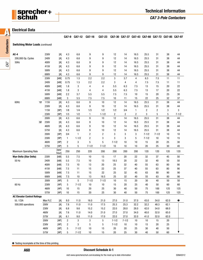
Switching Motor Loads (continued)
AC-4 230V [A] 4.3 6.6 9 9 12 14 16.5 25.5 31 38 44
200,000 Op. Cycles 240V [A] 4.3 6.6 9 9 12 14 16.5 25.5 31 38 44
50Hz 400V [A] 4.3 6.6 9 9 12 14 16.5 25.5 31 38 44
415V [A] 4.3 6.6 9 9 12 14 16.5 25.5 31 38 44
500V [A] 4.3 6.6 9 9 12 14 16.5 25.5 31 38 44
690V [A] 4.3 6.6 9 9 12 14 16.5 25.5 31 38 44
230V [kW] 0.75 1.5 2.2 2.2 3 3.7 4 6.3 7.5 11 11
240V [kW] 0.75 1.5 2.2 2.2 3 4 4 7.5 7.5 11 11
400V [kW] 1.8 3 4 4 5.5 6.3 7.5 13 15 20 22
415V [kW] 1.8 3 4 4 5.5 6.3 7.5 13 17 20 22
500V [kW] 2.2 3.7 5.5 5.5 7.5 7.5 10 15 20 25 30
690V [kW] 3 5.5 7.5 7.5 10 11 15 22 25 32 37
60Hz 1Ø 115V [A] 4.3 6.6 9 10 12 14 16.5 25.5 31 38 44
230V [A] 4.3 6.6 9 10 12 14 16.5 25.5 31 38 44
115V [HP] 1/8 1/4 1/3 1/2 1/2 3/4 1 2 2 3 3
230V [HP] 1/3 1/2 1 1-1/2 2 2 2 3 5 5 7-1/2
200V [A] 4.3 6.6 9 10 12 14 16.5 25.5 31 38 44
3Ø 230V [A] 4.3 6.6 9 10 12 14 16.5 25.5 31 38 44
460V [A] 4.3 6.6 9 10 12 14 16.5 25.5 31 38 44
575V [A] 4.3 6.6 9 10 12 14 16.5 25.5 31 38 44
200V [HP] 3/4 1 2 2 3 3 3 7-1/2 7-1/2 10 10
230V [HP] 1 1-1/2 2 3 3 3 5 7-1/2 10 10 15
460V [HP] 2 3 5 5 7-1/2 10 10 15 20 25 30
575V [HP] 3 5 7-1/2 7-1/2 10 10 10 20 25 30 40
Maximum Operating Rate [ops/hour]
250 250 220 200 200 200 200 120 120 120 120
Wye-Delta (Star Delta) 230V [kW] 5.5 7.5 10 13 17 20 22 32 37 45 50
50 Hz 240V [kW] 5.5 7.5 10 13 18.5 20 22 32 40 50 50
400V [kW] 7.5 10 13 20 25 32 40 55 63 80 90
415V [kW] 7.5 11 15 22 25 37 40 55 63 80 90
500V [kW] 7.5 11 15 22 25 32 45 63 80 90 90
690V [kW] 7.5 10 13 18.5 25 32 40 55 63 80 90
200V [HP] 5 5 7-1/2 7-1/2 10 15 20 30 40 50 50
60 Hz 230V [HP] 5 7-1/2 10 10 15 20 25 40 50 60 60
460V [HP] 10 15 20 25 30 40 50 75 100 125 125
575V [HP] 10 15 20 25 30 40 50 75 100 125 125
AC Elevator Control Ratings
UL / CSA Max FLC [A] 8.0 11.0 16.0 21.0 27.0 31.0 37.0 43.0 54.0 62.0 ➊
500,000 operations 200V [A] 7.8 11.0 11.0 17.5 25.3 25.3 32.2 32.2 48.3 62.1
230V [A] 6.8 9.6 15.2 15.2 22.0 28.0 28.0 42.0 54.0 68.0
460V [A] 7.6 11.0 14.0 21.0 27.0 27.0 34.0 40.0 52.0 65.0
575V [A] 6.1 9.0 11.0 17.0 22.0 27.0 32.0 41.0 52.0 62.0
200V [HP] 2 3 3 5 7-1/2 7-1/2 10 10 15 20
230V [HP] 2 3 5 5 7-1/2 10 10 15 20 25
460V [HP] 5 7-1/2 10 15 20 20 25 30 40 50
575V [HP] 5 7-1/2 10 15 20 25 30 40 50 60
➊ Testing incomplete at the time of this printing.
A61
Cont
acto
rs
A
visit www.sprecherschuh.com/ecatalog for the most up to date informationSSNA2012
CA7
Discount Schedule A-1
Technical InformationCA7 3-Pole Contactors
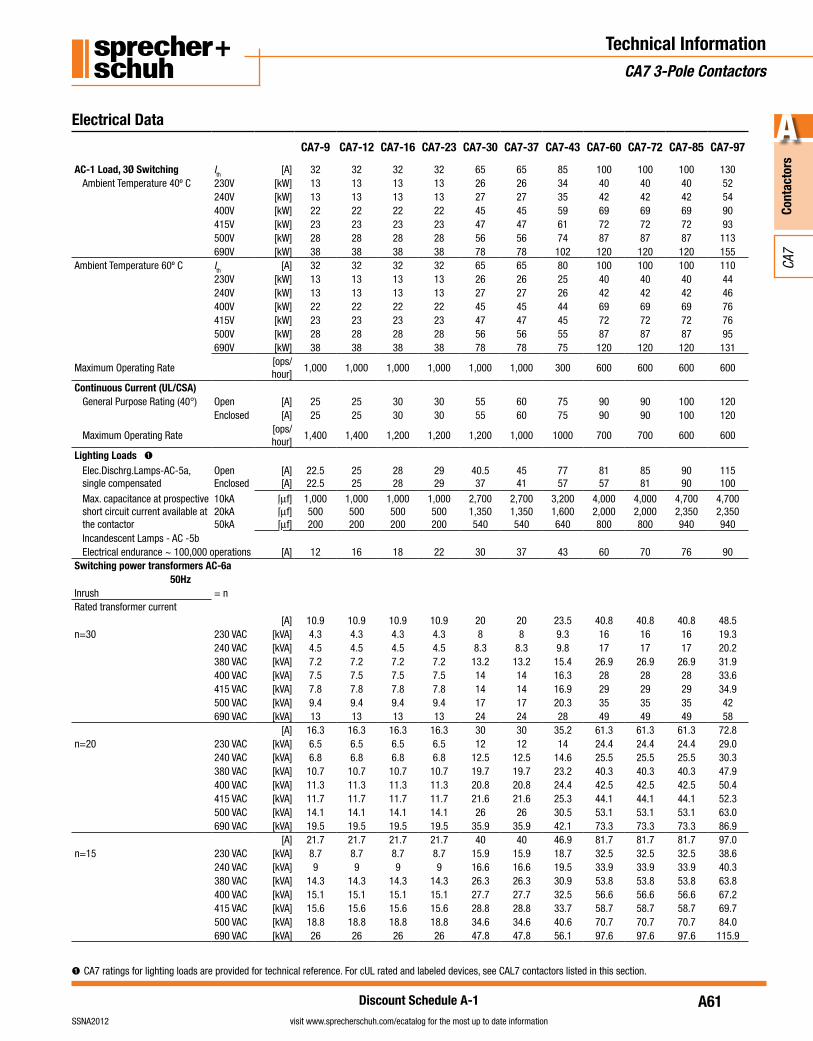
➊ CA7 ratings for lighting loads are provided for technical reference. For cUL rated and labeled devices, see CAL7 contactors listed in this section.
Electrical Data
CA7-9 CA7-12 CA7-16 CA7-23 CA7-30 CA7-37 CA7-43 CA7-60 CA7-72 CA7-85 CA7-97
AC-1 Load, 3Ø Switching Ith [A] 32 32 32 32 65 65 85 100 100 100 130Ambient Temperature 40º C 230V [kW] 13 13 13 13 26 26 34 40 40 40 52
240V [kW] 13 13 13 13 27 27 35 42 42 42 54400V [kW] 22 22 22 22 45 45 59 69 69 69 90415V [kW] 23 23 23 23 47 47 61 72 72 72 93500V [kW] 28 28 28 28 56 56 74 87 87 87 113690V [kW] 38 38 38 38 78 78 102 120 120 120 155
Ambient Temperature 60º C Ith [A] 32 32 32 32 65 65 80 100 100 100 110230V [kW] 13 13 13 13 26 26 25 40 40 40 44240V [kW] 13 13 13 13 27 27 26 42 42 42 46400V [kW] 22 22 22 22 45 45 44 69 69 69 76415V [kW] 23 23 23 23 47 47 45 72 72 72 76500V [kW] 28 28 28 28 56 56 55 87 87 87 95690V [kW] 38 38 38 38 78 78 75 120 120 120 131
Maximum Operating Rate [ops/hour]
1,000 1,000 1,000 1,000 1,000 1,000 300 600 600 600 600
Continuous Current (UL/CSA)General Purpose Rating (40°) Open [A] 25 25 30 30 55 60 75 90 90 100 120
Enclosed [A] 25 25 30 30 55 60 75 90 90 100 120
Maximum Operating Rate [ops/hour]
1,400 1,400 1,200 1,200 1,200 1,000 1000 700 700 600 600
Lighting Loads ➊Elec.Dischrg.Lamps-AC-5a, single compensated
OpenEnclosed
[A][A]
22.522.5
2525
2828
2929
40.537
4541
7757
8157
8581
9090
115100
Max. capacitance at prospective short circuit current available at the contactor
10kA20kA50kA
[mf][mf][mf]
1,000500200
1,000500200
1,000500200
1,000500200
2,7001,350540
2,7001,350540
3,2001,600640
4,0002,000800
4,0002,000800
4,7002,350940
4,7002,350940
Incandescent Lamps - AC -5bElectrical endurance ~ 100,000 operations [A] 12 16 18 22 30 37 43 60 70 76 90
Switching power transformers AC-6a50Hz
Inrush = nRated transformer current
[A] 10.9 10.9 10.9 10.9 20 20 23.5 40.8 40.8 40.8 48.5n=30 230 VAC [kVA] 4.3 4.3 4.3 4.3 8 8 9.3 16 16 16 19.3
240 VAC [kVA] 4.5 4.5 4.5 4.5 8.3 8.3 9.8 17 17 17 20.2380 VAC [kVA] 7.2 7.2 7.2 7.2 13.2 13.2 15.4 26.9 26.9 26.9 31.9400 VAC [kVA] 7.5 7.5 7.5 7.5 14 14 16.3 28 28 28 33.6415 VAC [kVA] 7.8 7.8 7.8 7.8 14 14 16.9 29 29 29 34.9500 VAC [kVA] 9.4 9.4 9.4 9.4 17 17 20.3 35 35 35 42690 VAC [kVA] 13 13 13 13 24 24 28 49 49 49 58
[A] 16.3 16.3 16.3 16.3 30 30 35.2 61.3 61.3 61.3 72.8n=20 230 VAC [kVA] 6.5 6.5 6.5 6.5 12 12 14 24.4 24.4 24.4 29.0
240 VAC [kVA] 6.8 6.8 6.8 6.8 12.5 12.5 14.6 25.5 25.5 25.5 30.3380 VAC [kVA] 10.7 10.7 10.7 10.7 19.7 19.7 23.2 40.3 40.3 40.3 47.9400 VAC [kVA] 11.3 11.3 11.3 11.3 20.8 20.8 24.4 42.5 42.5 42.5 50.4415 VAC [kVA] 11.7 11.7 11.7 11.7 21.6 21.6 25.3 44.1 44.1 44.1 52.3500 VAC [kVA] 14.1 14.1 14.1 14.1 26 26 30.5 53.1 53.1 53.1 63.0690 VAC [kVA] 19.5 19.5 19.5 19.5 35.9 35.9 42.1 73.3 73.3 73.3 86.9
[A] 21.7 21.7 21.7 21.7 40 40 46.9 81.7 81.7 81.7 97.0n=15 230 VAC [kVA] 8.7 8.7 8.7 8.7 15.9 15.9 18.7 32.5 32.5 32.5 38.6
240 VAC [kVA] 9 9 9 9 16.6 16.6 19.5 33.9 33.9 33.9 40.3380 VAC [kVA] 14.3 14.3 14.3 14.3 26.3 26.3 30.9 53.8 53.8 53.8 63.8400 VAC [kVA] 15.1 15.1 15.1 15.1 27.7 27.7 32.5 56.6 56.6 56.6 67.2415 VAC [kVA] 15.6 15.6 15.6 15.6 28.8 28.8 33.7 58.7 58.7 58.7 69.7500 VAC [kVA] 18.8 18.8 18.8 18.8 34.6 34.6 40.6 70.7 70.7 70.7 84.0690 VAC [kVA] 26 26 26 26 47.8 47.8 56.1 97.6 97.6 97.6 115.9
A62
Cont
acto
rs
A
visit www.sprecherschuh.com/ecatalog for the most up to date information SSNA2012
CA7
Discount Schedule A-1
Technical InformationCA7 3-Pole Contactors
Electrical Data
CA7-9 CA7-12 CA7-16 CA7-23 CA7-30 CA7-37 CA7-43 CA7-60 CA7-72 CA7-85 CA7-97
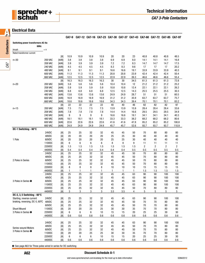
Switching power transformers AC-6a60Hz
Inrush = nRated transformer current
[A] 10.9 10.9 10.9 10.9 20 20 23 40.8 40.8 40.8 48.5n=30 200 VAC [kVA] 3.8 3.8 3.8 3.8 6.9 6.9 8.0 14.1 14.1 14.1 16.8
208 VAC [kVA] 3.9 3.9 3.9 3.9 7.2 7.2 8.3 14.7 14.7 14.7 17.5240 VAC [kVA] 4.5 4.5 4.5 4.5 8.3 8.3 9.6 17 17 17 20.2480 VAC [kVA] 9.1 9.1 9.1 9.1 16.6 16.6 19.1 33.9 33.9 33.9 40.3600 VAC [kVA] 11.3 11.3 11.3 11.3 20.8 20.8 23.9 42.4 42.4 42.4 50.4660 VAC [kVA] 12.5 12.5 12.5 12.5 22.9 22.9 26.3 46.6 46.6 46.6 55.4
[A] 16.3 16.3 16.3 16.3 30 30 34.5 61.3 61.3 61.3 72.8n=20 200 VAC [kVA] 5.6 5.6 5.6 5.6 10.4 10.4 12 21.2 21.2 21.2 25.2
208 VAC [kVA] 5.9 5.9 5.9 5.9 10.8 10.8 12.4 22.1 22.1 22.1 26.2240 VAC [kVA] 6.8 6.8 6.8 6.8 12.5 12.5 14.3 25.5 25.5 25.5 30.3480 VAC [kVA] 13.6 13.6 13.6 13.6 24.9 24.9 28.7 51 51 51 60.5600 VAC [kVA] 16.9 16.9 16.9 16.9 31.2 31.2 35.9 63.7 63.7 63.7 75.7660 VAC [kVA] 18.6 18.6 18.6 18.6 34.3 34.3 39.4 70.1 70.1 70.1 83.2
[A] 22 22 22 22 40 40 46 82 82 82 97n=15 200 VAC [kVA] 7.5 7.5 7.5 7.5 13.9 13.9 15.9 28.4 28.4 28.4 33.6
208 VAC [kVA] 7.8 7.8 7.8 7.8 14.4 14.4 16.6 29.5 29.5 29.5 34.9240 VAC [kVA] 9 9 9 9 16.6 16.6 19.1 34.1 34.1 34.1 40.3480 VAC [kVA] 18.1 18.1 18.1 18.1 33.3 33.3 38.2 68.2 68.2 68.2 80.6600 VAC [kVA] 22.6 22.6 22.6 22.6 41.6 41.6 47.8 85.2 85.2 85.2 100.8660 VAC [kVA] 24.9 24.9 24.9 24.9 45.7 45.7 52.6 93.7 93.7 93.7 110.9
DC-1 Switching - 60°C24VDC [A] 25 25 32 32 45 45 50 70 80 80 8048VDC [A] 20 20 20 20 25 25 30 40 40 40 40
1 Pole 60VDC [A] 20 20 20 20 25 25 30 40 40 40 40110VDC [A] 6 6 6 6 8 8 9 11 11 11 11220VDC [A] 1.5 1.5 1.5 1.5 1.5 1.5 1.5 2 2 2 2440VDC [A] 0.4 0.4 0.4 0.4 0.4 0.4 0.5 0.5 0.5 0.5 0.524VDC [A] 25 25 32 32 45 45 50 70 80 80 8048VDC [A] 25 25 32 32 45 45 50 70 80 80 80
2 Poles in Series 60VDC [A] 25 25 32 32 45 45 50 70 80 80 80110VDC [A] 25 25 32 32 45 45 50 70 80 80 80220VDC [A] 8 8 8 8 10 10 10 15 15 15 15440VDC [A] 1 1 1 1 1 1 1 1.5 1.5 1.5 1.524VDC [A] 25 25 32 32 45 45 63 90 90 100 10048VDC [A] 25 25 32 32 45 45 63 90 90 100 100
3 Poles in Series ➊ 60VDC [A] 25 25 32 32 45 45 63 90 90 100 100110VDC [A] 25 25 32 32 45 45 63 90 90 100 100220VDC [A] 25 25 32 32 45 45 50 70 80 80 80440VDC [A] 3 3 3 3 3.5 3.5 4 5 5 5 5
DC-2, 3, 5 Switching - 60°CStarting, reverse current braking, reversing, DC-5, 60ºC
24VDC [A] 25 25 32 32 45 45 63 90 90 100 10048VDC [A] 25 25 32 32 45 45 50 70 70 80 8060VDC [A] 25 25 32 32 45 45 50 70 70 80 80
Shunt Wound 110VDC [A] 20 20 25 25 30 30 35 70 70 80 803 Poles in Series ➊ 220VDC [A] 6 6 6 10 15 15 20 25 25 30 30
440VDC [A] 0.6 0.6 0.6 0.6 0.6 0.6 0.6 0.6 0.6 0.6 0.6
Series-wound Motors3 Poles in Series ➊
24VDC [A] 25 25 32 32 45 45 63 90 90 100 10048VDC [A] 25 25 32 32 45 45 50 70 70 80 8060VDC [A] 25 25 32 32 45 45 50 70 70 80 80110VDC [A] 20 20 25 25 30 30 35 70 70 80 80220VDC [A] 6 6 6 10 15 15 20 25 25 30 30440VDC [A] 0.6 0.6 0.6 0.6 0.6 0.6 0.6 0.6 0.6 0.6 0.6
➊See page A63 for Three poles wired in series for DC switching
A63
Cont
acto
rs
A
visit www.sprecherschuh.com/ecatalog for the most up to date informationSSNA2012
CA7
Discount Schedule A-1
Technical InformationCA7 3-Pole Contactors
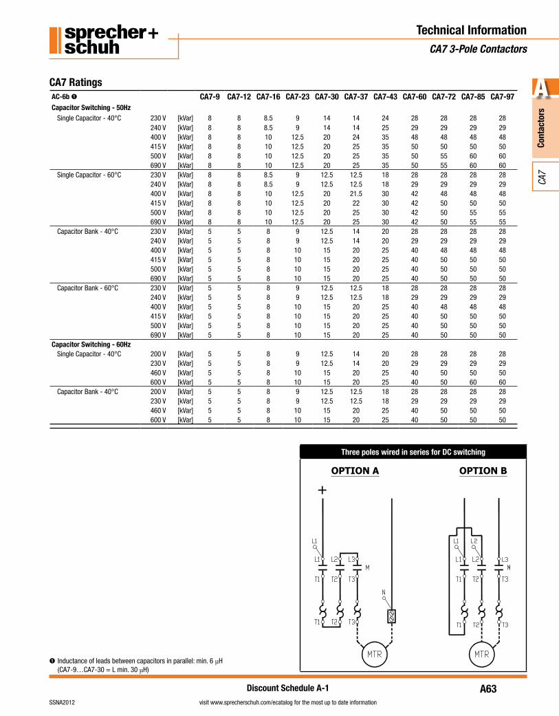
CA7 Ratings
➊ Inductance of leads between capacitors in parallel: min. 6 µH (CA7-9…CA7-30 = L min. 30 µH)
AC-6b ➊ CA7-9 CA7-12 CA7-16 CA7-23 CA7-30 CA7-37 CA7-43 CA7-60 CA7-72 CA7-85 CA7-97Capacitor Switching - 50Hz
Single Capacitor - 40°C 230 V [kVar] 8 8 8.5 9 14 14 24 28 28 28 28240 V [kVar] 8 8 8.5 9 14 14 25 29 29 29 29400 V [kVar] 8 8 10 12.5 20 24 35 48 48 48 48415 V [kVar] 8 8 10 12.5 20 25 35 50 50 50 50500 V [kVar] 8 8 10 12.5 20 25 35 50 55 60 60690 V [kVar] 8 8 10 12.5 20 25 35 50 55 60 60
Single Capacitor - 60°C 230 V [kVar] 8 8 8.5 9 12.5 12.5 18 28 28 28 28240 V [kVar] 8 8 8.5 9 12.5 12.5 18 29 29 29 29400 V [kVar] 8 8 10 12.5 20 21.5 30 42 48 48 48415 V [kVar] 8 8 10 12.5 20 22 30 42 50 50 50500 V [kVar] 8 8 10 12.5 20 25 30 42 50 55 55690 V [kVar] 8 8 10 12.5 20 25 30 42 50 55 55
Capacitor Bank - 40°C 230 V [kVar] 5 5 8 9 12.5 14 20 28 28 28 28240 V [kVar] 5 5 8 9 12.5 14 20 29 29 29 29400 V [kVar] 5 5 8 10 15 20 25 40 48 48 48415 V [kVar] 5 5 8 10 15 20 25 40 50 50 50500 V [kVar] 5 5 8 10 15 20 25 40 50 50 50690 V [kVar] 5 5 8 10 15 20 25 40 50 50 50
Capacitor Bank - 60°C 230 V [kVar] 5 5 8 9 12.5 12.5 18 28 28 28 28240 V [kVar] 5 5 8 9 12.5 12.5 18 29 29 29 29400 V [kVar] 5 5 8 10 15 20 25 40 48 48 48415 V [kVar] 5 5 8 10 15 20 25 40 50 50 50500 V [kVar] 5 5 8 10 15 20 25 40 50 50 50690 V [kVar] 5 5 8 10 15 20 25 40 50 50 50
Capacitor Switching - 60HzSingle Capacitor - 40°C 200 V [kVar] 5 5 8 9 12.5 14 20 28 28 28 28
230 V [kVar] 5 5 8 9 12.5 14 20 29 29 29 29460 V [kVar] 5 5 8 10 15 20 25 40 50 50 50600 V [kVar] 5 5 8 10 15 20 25 40 50 60 60
Capacitor Bank - 40°C 200 V [kVar] 5 5 8 9 12.5 12.5 18 28 28 28 28230 V [kVar] 5 5 8 9 12.5 12.5 18 29 29 29 29460 V [kVar] 5 5 8 10 15 20 25 40 50 50 50600 V [kVar] 5 5 8 10 15 20 25 40 50 50 50
Three poles wired in series for DC switching
OPTION A OPTION B
+
A64
Cont
acto
rs
A
visit www.sprecherschuh.com/ecatalog for the most up to date information SSNA2012
CA7
Discount Schedule A-1
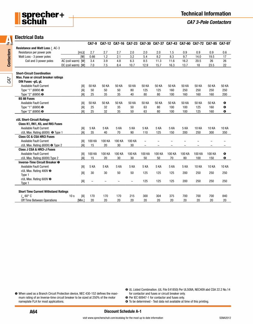
Electrical DataCA7-9 CA7-12 CA7-16 CA7-23 CA7-30 CA7-37 CA7-43 CA7-60 CA7-72 CA7-85 CA7-97
Resistance and Watt Loss Ie AC-3Resistance per power pole [mΩ] 2.7 2.7 2.7 2.0 2.0 2.0 1.5 0.9 0.9 0.9 0.6Watt Loss - 3 power poles [W] 0.66 1.2 2.1 3.2 5.4 8.2 8.3 9.7 14.0 19.5 17
Coil and 3 power poles AC (coil warm) [W] 3.4 3.9 4.8 6.3 8.5 11.3 11.6 16.2 20.5 26 26DC (coil warm) [W] 7.0 7.5 8.4 10.7 12.9 15.7 16.3 13.7 18 23.5 22
Short-Circuit CoordinationMax. Fuse or circuit breaker ratings
DIN Fuses -gG, gLAvailable Fault Current [A] 50 KA 50 KA 50 KA 50 KA 50 KA 50 KA 50 KA 50 KA 50 KA 50 KA 50 KAType “1” (690V) ➌ [A] 50 50 50 80 125 125 160 250 250 250 250Type “2” (690V) ➌ [A] 25 35 35 40 80 80 100 160 160 160 200
BS 88 FusesAvailable Fault Current [A] 50 KA 50 KA 50 KA 50 KA 50 KA 50 KA 50 KA 50 KA 50 KA 50 KA ➍
Type “1” (690V) ➌ [A] 25 32 35 50 63 80 100 100 125 160 ➍
Type “2” (690V) ➌ [A] 25 32 35 50 63 80 100 100 125 160 ➍
cUL Short-Circuit RatingsClass K1, RK1, K5, and RK5 Fuses
Available Fault Current [A] 5 KA 5 KA 5 KA 5 KA 5 KA 5 KA 5 KA 5 KA 10 KA 10 KA 10 KAcUL Max. Rating (600V) ➋ Type 1 [A] 35 40 70 90 110 125 150 200 250 300 350
Class CC & CSA HRCI FusesAvailable Fault Current [A] 100 KA 100 KA 100 KA 100 KA ~ ~ ~ ~ ~ ~ ~cUL Max. Rating (600V) ➋ Type 2 [A] 15 20 30 30 ~ ~ ~ ~ ~ ~ ~
Class J CSA & HRCI-J FusesAvailable Fault Current [A] 100 KA 100 KA 100 KA 100 KA 100 KA 100 KA 100 KA 100 KA 100 KA 100 KA ➍
cUL Max. Rating (600V) Type 2 [A] 15 20 30 30 50 50 70 80 100 150 ➍
Inverse-Time Circuit Breaker ➊Available Fault Current [A] 5 KA 5 KA 5 KA 5 KA 5 KA 5 KA 5 KA 5 KA 10 KA 10 KA 10 KAcUL Max. Rating 480V ➋
Type 1[A] 30 30 50 50 125 125 125 200 250 250 250
cUL Max. Rating 600V ➋
Type 1[A] ~ ~ ~ ~ 125 125 125 200 250 250 250
Short Time Current Withstand RatingsIcw 60° C 10 s [A] 170 170 170 215 300 304 375 700 700 700 840Off Time Between Operations [Min.] 20 20 20 20 20 20 20 20 20 20 20
Technical InformationCA7 3-Pole Contactors
➊ When used as a Branch Circuit Protection device, NEC 430-152 defines the maxi-mum rating of an Inverse-time circuit breaker to be sized at 250% of the motor nameplate FLA for most applications.
➋ UL Listed Combination. (UL File E41850) Per UL508A, NEC409 abd CSA 22.2 No.14 for contactor and fuses or circuit breaker only.
➌ Per IEC 60947-1 for contactor and fuses only.➍ To be determined - Test data not available at time of this printing.
A65
Cont
acto
rs
A
visit www.sprecherschuh.com/ecatalog for the most up to date informationSSNA2012
CA7
Discount Schedule A-1
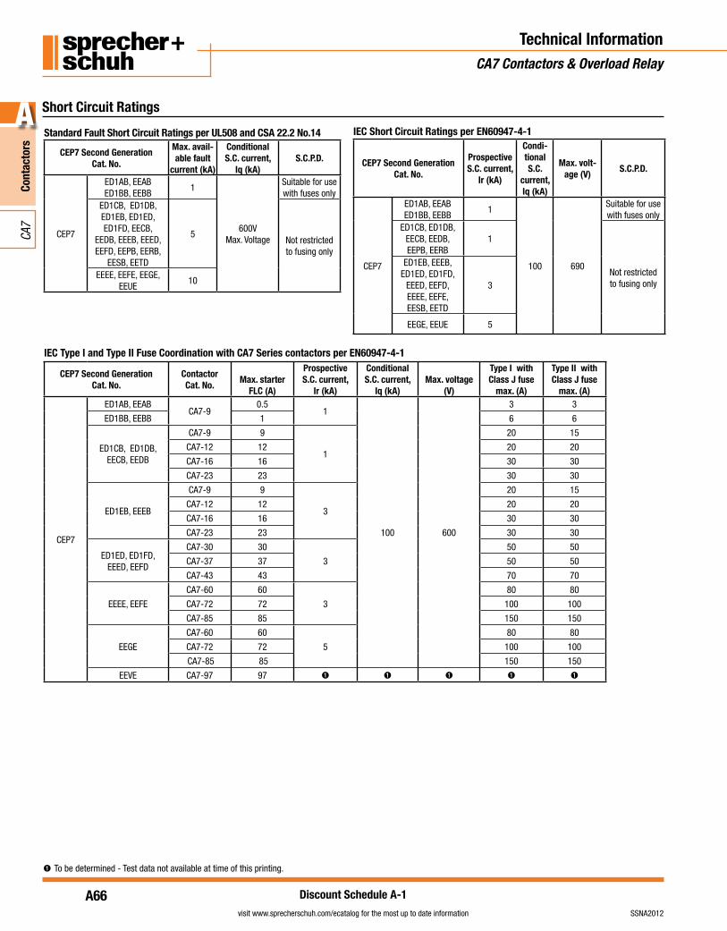
Short Circuit Ratings
Technical InformationCA7 Contactors & Overload Relay
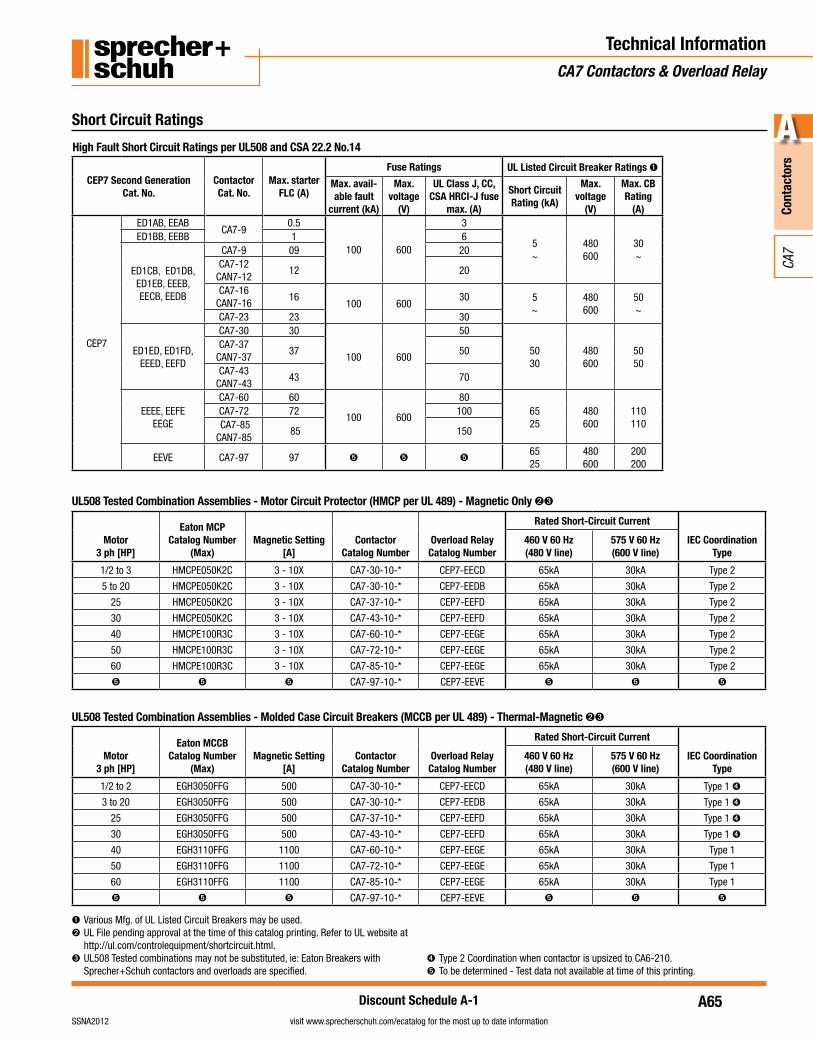
High Fault Short Circuit Ratings per UL508 and CSA 22.2 No.14
CEP7 Second Generation Cat. No.
Contactor Cat. No.
Max. starter FLC (A)
Fuse Ratings UL Listed Circuit Breaker Ratings ➊
Max. avail-able fault
current (kA)
Max. voltage
(V)
UL Class J, CC, CSA HRCI-J fuse
max. (A)
Short Circuit Rating (kA)
Max. voltage
(V)
Max. CB Rating
(A)
CEP7
ED1AB, EEABCA7-9
0.5
100 600
3
5~
480600
30~
ED1BB, EEBB 1 6
ED1CB, ED1DB, ED1EB, EEEB,EECB, EEDB
CA7-9 09 20CA7-12
CAN7-1212 20
CA7-16CAN7-16
16100 600
30 5~
480600
50~
CA7-23 23 30
ED1ED, ED1FD, EEED, EEFD
CA7-30 30
100 600
50
5030
480600
5050
CA7-37CAN7-37
37 50
CA7-43CAN7-43
43 70
EEEE, EEFEEEGE
CA7-60 60
100 600
806525
480600
110110
CA7-72 72 100 CA7-85CAN7-85
85 150
EEVE CA7-97 97 ➎ ➎ ➎6525
480600
200200
➊ Various Mfg. of UL Listed Circuit Breakers may be used.➋ UL File pending approval at the time of this catalog printing. Refer to UL website at
http://ul.com/controlequipment/shortcircuit.html.➌ UL508 Tested combinations may not be substituted, ie: Eaton Breakers with
Sprecher+Schuh contactors and overloads are specified.➍ Type 2 Coordination when contactor is upsized to CA6-210.➎ To be determined - Test data not available at time of this printing.
UL508 Tested Combination Assemblies - Molded Case Circuit Breakers (MCCB per UL 489) - Thermal-Magnetic ➋➌
Motor3 ph [HP]
Eaton MCCBCatalog Number
(Max)Magnetic Setting
[A]Contactor
Catalog NumberOverload RelayCatalog Number
Rated Short-Circuit Current
IEC CoordinationType
460 V 60 Hz(480 V line)
575 V 60 Hz(600 V line)
1/2 to 2 EGH3050FFG 500 CA7-30-10-* CEP7-EECD 65kA 30kA Type 1 ➍
3 to 20 EGH3050FFG 500 CA7-30-10-* CEP7-EEDB 65kA 30kA Type 1 ➍
25 EGH3050FFG 500 CA7-37-10-* CEP7-EEFD 65kA 30kA Type 1 ➍
30 EGH3050FFG 500 CA7-43-10-* CEP7-EEFD 65kA 30kA Type 1 ➍
40 EGH3110FFG 1100 CA7-60-10-* CEP7-EEGE 65kA 30kA Type 1
50 EGH3110FFG 1100 CA7-72-10-* CEP7-EEGE 65kA 30kA Type 1
60 EGH3110FFG 1100 CA7-85-10-* CEP7-EEGE 65kA 30kA Type 1
➎ ➎ ➎ CA7-97-10-* CEP7-EEVE ➎ ➎ ➎
UL508 Tested Combination Assemblies - Motor Circuit Protector (HMCP per UL 489) - Magnetic Only ➋➌
Motor3 ph [HP]
Eaton MCPCatalog Number
(Max)Magnetic Setting
[A]Contactor
Catalog NumberOverload RelayCatalog Number
Rated Short-Circuit Current
IEC CoordinationType
460 V 60 Hz(480 V line)
575 V 60 Hz(600 V line)
1/2 to 3 HMCPE050K2C 3 - 10X CA7-30-10-* CEP7-EECD 65kA 30kA Type 2
5 to 20 HMCPE050K2C 3 - 10X CA7-30-10-* CEP7-EEDB 65kA 30kA Type 2
25 HMCPE050K2C 3 - 10X CA7-37-10-* CEP7-EEFD 65kA 30kA Type 2
30 HMCPE050K2C 3 - 10X CA7-43-10-* CEP7-EEFD 65kA 30kA Type 2
40 HMCPE100R3C 3 - 10X CA7-60-10-* CEP7-EEGE 65kA 30kA Type 2
50 HMCPE100R3C 3 - 10X CA7-72-10-* CEP7-EEGE 65kA 30kA Type 2
60 HMCPE100R3C 3 - 10X CA7-85-10-* CEP7-EEGE 65kA 30kA Type 2
➎ ➎ ➎ CA7-97-10-* CEP7-EEVE ➎ ➎ ➎
A66
Cont
acto
rs
A
visit www.sprecherschuh.com/ecatalog for the most up to date information SSNA2012
CA7
Discount Schedule A-1
IEC Type I and Type II Fuse Coordination with CA7 Series contactors per EN60947-4-1
CEP7 Second Generation Cat. No.
Contactor Cat. No.
Max. starter FLC (A)
Prospective S.C. current,
Ir (kA)
Conditional S.C. current,
Iq (kA)Max. voltage
(V)
Type I with Class J fuse
max. (A)
Type II with Class J fuse
max. (A)
CEP7
ED1AB, EEABCA7-9
0.51
100 600
3 3
ED1BB, EEBB 1 6 6
ED1CB, ED1DB, EECB, EEDB
CA7-9 9
1
20 15
CA7-12 12 20 20
CA7-16 16 30 30
CA7-23 23 30 30
ED1EB, EEEB
CA7-9 9
3
20 15
CA7-12 12 20 20
CA7-16 16 30 30
CA7-23 23 30 30
ED1ED, ED1FD, EEED, EEFD
CA7-30 30
3
50 50
CA7-37 37 50 50
CA7-43 43 70 70
EEEE, EEFE
CA7-60 60
3
80 80
CA7-72 72 100 100
CA7-85 85 150 150
EEGE
CA7-60 60
5
80 80
CA7-72 72 100 100
CA7-85 85 150 150
EEVE CA7-97 97 ➊ ➊ ➊ ➊ ➊
IEC Short Circuit Ratings per EN60947-4-1
CEP7 Second Generation Cat. No.
Prospective S.C. current,
Ir (kA)
Condi-tional S.C.
current, Iq (kA)
Max. volt-age (V)
S.C.P.D.
CEP7
ED1AB, EEABED1BB, EEBB
1
100 690
Suitable for use with fuses only
ED1CB, ED1DB, EECB, EEDB, EEPB, EERB
1
Not restricted to fusing only
ED1EB, EEEB, ED1ED, ED1FD,
EEED, EEFD, EEEE, EEFE, EESB, EETD
3
EEGE, EEUE 5
Standard Fault Short Circuit Ratings per UL508 and CSA 22.2 No.14
CEP7 Second Generation Cat. No.
Max. avail-able fault
current (kA)
Conditional S.C. current,
Iq (kA)S.C.P.D.
CEP7
ED1AB, EEABED1BB, EEBB
1
600VMax. Voltage
Suitable for use with fuses only
ED1CB, ED1DB, ED1EB, ED1ED, ED1FD, EECB,
EEDB, EEEB, EEED, EEFD, EEPB, EERB,
EESB, EETD
5Not restricted to fusing only
EEEE, EEFE, EEGE, EEUE
10
Short Circuit Ratings
Technical InformationCA7 Contactors & Overload Relay
➊ To be determined - Test data not available at time of this printing.
A67
Cont
acto
rs
A
visit www.sprecherschuh.com/ecatalog for the most up to date informationSSNA2012
CA7
Discount Schedule A-1
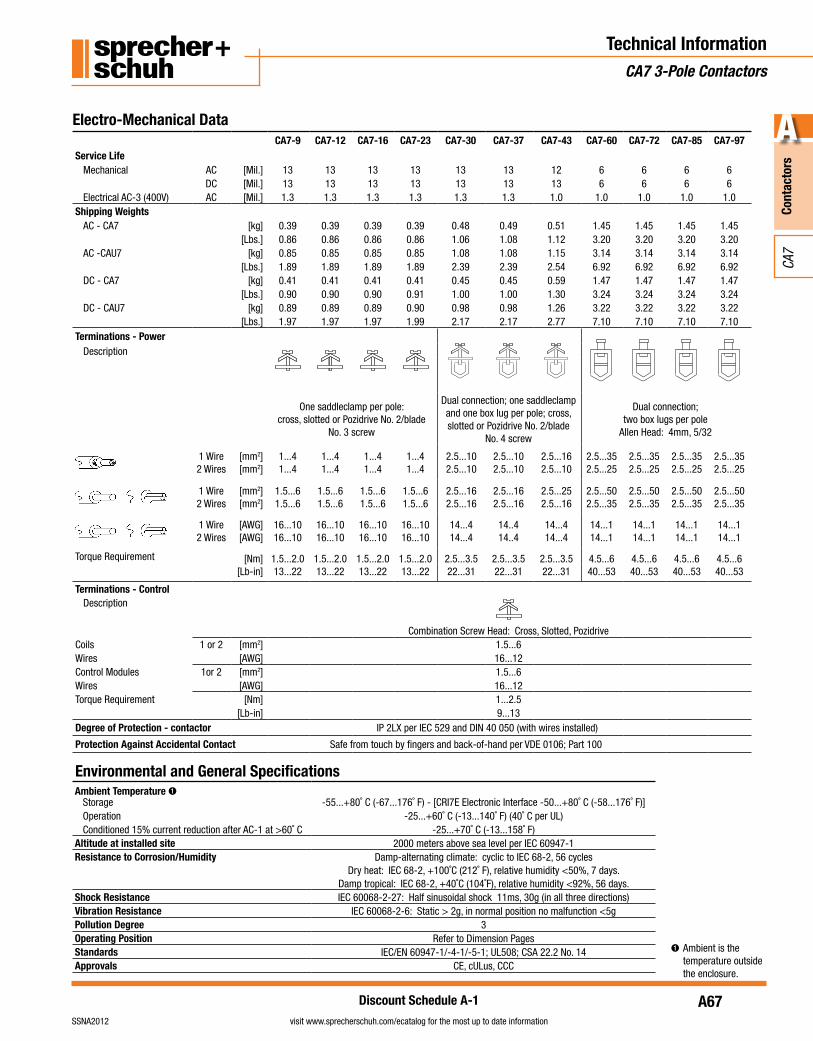
Electro-Mechanical Data
Technical InformationCA7 3-Pole Contactors
CA7-9 CA7-12 CA7-16 CA7-23 CA7-30 CA7-37 CA7-43 CA7-60 CA7-72 CA7-85 CA7-97Service Life
Mechanical AC [Mil.] 13 13 13 13 13 13 12 6 6 6 6DC [Mil.] 13 13 13 13 13 13 13 6 6 6 6
Electrical AC-3 (400V) AC [Mil.] 1.3 1.3 1.3 1.3 1.3 1.3 1.0 1.0 1.0 1.0 1.0Shipping Weights
AC - CA7 [kg] 0.39 0.39 0.39 0.39 0.48 0.49 0.51 1.45 1.45 1.45 1.45[Lbs.] 0.86 0.86 0.86 0.86 1.06 1.08 1.12 3.20 3.20 3.20 3.20
AC -CAU7 [kg] 0.85 0.85 0.85 0.85 1.08 1.08 1.15 3.14 3.14 3.14 3.14[Lbs.] 1.89 1.89 1.89 1.89 2.39 2.39 2.54 6.92 6.92 6.92 6.92
DC - CA7 [kg] 0.41 0.41 0.41 0.41 0.45 0.45 0.59 1.47 1.47 1.47 1.47[Lbs.] 0.90 0.90 0.90 0.91 1.00 1.00 1.30 3.24 3.24 3.24 3.24
DC - CAU7 [kg] 0.89 0.89 0.89 0.90 0.98 0.98 1.26 3.22 3.22 3.22 3.22[Lbs.] 1.97 1.97 1.97 1.99 2.17 2.17 2.77 7.10 7.10 7.10 7.10
Terminations - PowerDescription
One saddleclamp per pole:cross, slotted or Pozidrive No. 2/blade
No. 3 screw
Dual connection; one saddleclamp and one box lug per pole; cross,slotted or Pozidrive No. 2/blade
No. 4 screw
Dual connection; two box lugs per pole
Allen Head: 4mm, 5/32
1 Wire2 Wires
[mm2][mm2]
1...41...4
1...41...4
1...41...4
1...41...4
2.5...102.5...10
2.5...102.5...10
2.5...162.5...10
2.5...352.5...25
2.5...352.5...25
2.5...352.5...25
2.5...352.5...25
1 Wire2 Wires
[mm2][mm2]
1.5...61.5...6
1.5...61.5...6
1.5...61.5...6
1.5...61.5...6
2.5...162.5...16
2.5...162.5...16
2.5...252.5...16
2.5...502.5...35
2.5...502.5...35
2.5...502.5...35
2.5...502.5...35
1 Wire2 Wires
[AWG][AWG]
16...1016...10
16...1016...10
16...1016...10
16...1016...10
14...414...4
14..414..4
14...414...4
14...114...1
14...114...1
14...114...1
14...114...1
Torque Requirement [Nm][Lb-in]
1.5...2.013...22
1.5...2.013...22
1.5...2.013...22
1.5...2.013...22
2.5...3.522...31
2.5...3.522...31
2.5...3.522...31
4.5...640...53
4.5...640...53
4.5...640...53
4.5...640...53
Terminations - ControlDescription
Combination Screw Head: Cross, Slotted, PozidriveCoils 1 or 2 [mm2] 1.5...6Wires [AWG] 16...12Control Modules 1or 2 [mm2] 1.5...6Wires [AWG] 16...12Torque Requirement [Nm] 1...2.5
[Lb-in] 9...13Degree of Protection - contactor IP 2LX per IEC 529 and DIN 40 050 (with wires installed)
Protection Against Accidental Contact Safe from touch by fingers and back-of-hand per VDE 0106; Part 100
Ambient Temperature ➊Storage -55...+80˚ C (-67...176˚ F) - [CRI7E Electronic Interface -50...+80˚ C (-58...176˚ F)]Operation -25...+60˚ C (-13...140˚ F) (40˚ C per UL)Conditioned 15% current reduction after AC-1 at >60˚ C -25...+70˚ C (-13...158˚ F)
Altitude at installed site 2000 meters above sea level per IEC 60947-1Resistance to Corrosion/Humidity Damp-alternating climate: cyclic to IEC 68-2, 56 cycles
Dry heat: IEC 68-2, +100˚C (212˚ F), relative humidity <50%, 7 days.Damp tropical: IEC 68-2, +40˚C (104˚F), relative humidity <92%, 56 days.
Shock Resistance IEC 60068-2-27: Half sinusoidal shock 11ms, 30g (in all three directions)Vibration Resistance IEC 60068-2-6: Static > 2g, in normal position no malfunction <5gPollution Degree 3Operating Position Refer to Dimension PagesStandards IEC/EN 60947-1/-4-1/-5-1; UL508; CSA 22.2 No. 14Approvals CE, cULus, CCC
Environmental and General Specifications
➊ Ambient is the temperature outside the enclosure.
A68
Cont
acto
rs
A
visit www.sprecherschuh.com/ecatalog for the most up to date information SSNA2012
CA7
Discount Schedule A-1
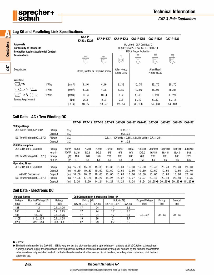
➊ ≤ 220V.➋ The hold-in demand of the CA7-9E…43E is very low but the pick-up demand is approximately 1 ampere at 24 VDC. When sizing (dimen-
sioning) a power supply for applications involving parallel switched contactors then multiply the peak demand by the number of contactors to be simultaneously switched and add to the hold-in demand of all other control circuit burdens, including other contactors, pilot devices, solenoids, etc.
Technical InformationCA7 3-Pole Contactors
Coil Data - AC / Two Winding DC
Lug Kit and Paralleling Link SpecificationsCA7-P-
KN23 / KL23CA7-P-K37 CA7-P-K43 CA7-P-K85 CA7-P-B23 CA7-P-B37
Approvals UL Listed; CSA Certified; CUL508; CSA 22.2 No. 14; IEC 60947-4
IP2LX Finger ProtectionConformity to StandardsProtection Against Accidental ContactTerminations
DescriptionCross, slotted or Pozidrive screw
Allen Head; 5mm, 3/16
Allen Head;7 mm, 15/32
Wire Size
1 Wire [mm2] 4...16 4..16 6...35 10...70 35...70 35...70
1 Wire [mm2] 4...25 4..25 6...50 10...95 35...95 35...95
1 Wire [AWG] 10...4 10...4 8...2 8..2/0 0...2/0 0...2/0
Torque Requirement [Nm] 2...3 2...3 3..6 8...12 6...12 6....12
[Lb-in] 18...27 18...27 27...54 72...108 54...108 54...108
CA7-9 CA7-12 CA7-16 CA7-23 CA7-30 CA7-37 CA7-43 CA7-60 CA7-72 CA7-85 CA7-97Voltage Range
AC: 50Hz, 60Hz, 50/60 Hz Pickup [xUs] 0.85...1.1Dropout [xUs] 0.3...0.6
DC: Two Winding (60D…97D) Pickup [xUs] 0.8...1.1 (9V coils = 0.65...1.3; 24V coils = 0.7...1.25)Dropout [xUs] 0.1...0.6
Coil ConsumptionAC: 50Hz, 60Hz, 50/60 Hz Pickup [VA/W] 70/50 70/50 70/50 70/50 80/60 80/60 130/90 200/110 200/110 200/110 400/240
Hold-in [VA/W] 8/2.6 8/2.6 8/2.6 9/3 9/3 9/3 10/3.2 16/4.5 16/4.5 16/4.5 24/9DC: Two Winding (60D…97D) Pickup [W] 120 120 120 200 200 200 200 200 200 200 325
Hold-in [W] 1.1 1.1 1.1 1.2 1.2 1.2 1.3 4.5 4.5 4.5 5.5Operating Times
AC: 50Hz, 60Hz, 50/60 Hz Pickup [ms] 15...30 15...30 15...30 15...30 15...30 15...30 15...30 20...40 20...40 20...40 20...40Dropout [ms] 10...60 10...60 10...60 10...60 10...60 10...60 10...60 10...60 10...60 10...60 20...40
with RC Suppressor Dropout [ms] 10...60 10...60 10...60 10...60 10...60 10...60 10...60 10...60 10...60 10...60 20...40DC: Two Winding (60D…97D) Pickup [ms] 17...26 17...26 15...27 15...27 15...27 15...27 15...27 20...40 20...40 20...40 15...25
Dropout [ms] 9...20 9...20 14...24 14...24 14...24 14...24 14...24 20...35 ➊ 20...35 ➊ 20...35 ➊ 15...25 ➊
Coil Data - Electronic DCVoltage Range Coil Consumption & Operating Times ➋Voltage Code
Nominal Voltage US[VDC]
Ratings[xUs]
Pickup [W] Hold-in [W] Dropout Voltage[xUs]
Pickup[ms]
Dropout[ms]CA7-9E…37E CA7-43E CA7-9E…37E CA7-43E
12E 12 0.7…1.25 17 24 1.7 2.5
0.3…0.4 20…50 20…5024E 24 0.7…1.25 17 24 1.7 2.548E 48…72 0.8…1.25 17 24 1.7 2.5110E 110…125 0.7…1.25 19 26 2 2.7220E 220…250 0.8…1.1 22 29 2.7 3.5
A69
Cont
acto
rs
A
visit www.sprecherschuh.com/ecatalog for the most up to date informationSSNA2012
CA7
Discount Schedule A-1
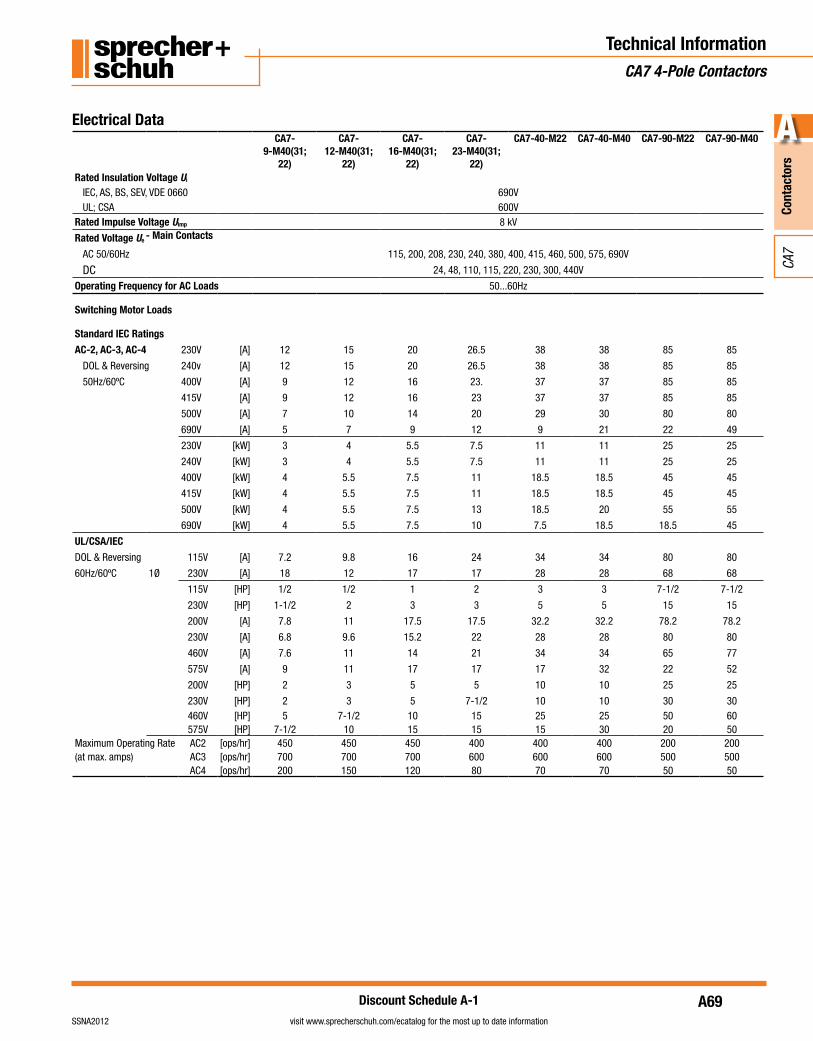
Electrical DataCA7-
9-M40(31; 22)
CA7-12-M40(31;
22)
CA7-16-M40(31;
22)
CA7-23-M40(31;
22)
CA7-40-M22 CA7-40-M40 CA7-90-M22 CA7-90-M40
Rated Insulation Voltage Ui
IEC, AS, BS, SEV, VDE 0660 690VUL; CSA 600V
Rated Impulse Voltage Uimp 8 kV
Rated Voltage Ue - Main Contacts
AC 50/60Hz 115, 200, 208, 230, 240, 380, 400, 415, 460, 500, 575, 690V
DC 24, 48, 110, 115, 220, 230, 300, 440V
Operating Frequency for AC Loads 50...60Hz
Switching Motor Loads
Standard IEC Ratings
AC-2, AC-3, AC-4 230V [A] 12 15 20 26.5 38 38 85 85
DOL & Reversing 240v [A] 12 15 20 26.5 38 38 85 85
50Hz/60ºC 400V [A] 9 12 16 23. 37 37 85 85
415V [A] 9 12 16 23 37 37 85 85
500V [A] 7 10 14 20 29 30 80 80
690V [A] 5 7 9 12 9 21 22 49
230V [kW] 3 4 5.5 7.5 11 11 25 25
240V [kW] 3 4 5.5 7.5 11 11 25 25
400V [kW] 4 5.5 7.5 11 18.5 18.5 45 45
415V [kW] 4 5.5 7.5 11 18.5 18.5 45 45
500V [kW] 4 5.5 7.5 13 18.5 20 55 55
690V [kW] 4 5.5 7.5 10 7.5 18.5 18.5 45
UL/CSA/IEC
DOL & Reversing 115V [A] 7.2 9.8 16 24 34 34 80 80
60Hz/60ºC 1Ø 230V [A] 18 12 17 17 28 28 68 68
115V [HP] 1/2 1/2 1 2 3 3 7-1/2 7-1/2
230V [HP] 1-1/2 2 3 3 5 5 15 15
200V [A] 7.8 11 17.5 17.5 32.2 32.2 78.2 78.2
230V [A] 6.8 9.6 15.2 22 28 28 80 80
460V [A] 7.6 11 14 21 34 34 65 77
575V [A] 9 11 17 17 17 32 22 52
200V [HP] 2 3 5 5 10 10 25 25
230V [HP] 2 3 5 7-1/2 10 10 30 30460V [HP] 5 7-1/2 10 15 25 25 50 60575V [HP] 7-1/2 10 15 15 15 30 20 50
Maximum Operating Rate AC2 [ops/hr] 450 450 450 400 400 400 200 200(at max. amps) AC3 [ops/hr] 700 700 700 600 600 600 500 500
AC4 [ops/hr] 200 150 120 80 70 70 50 50
Technical InformationCA7 4-Pole Contactors
A70
Cont
acto
rs
A
visit www.sprecherschuh.com/ecatalog for the most up to date information SSNA2012
CA7
Discount Schedule A-1
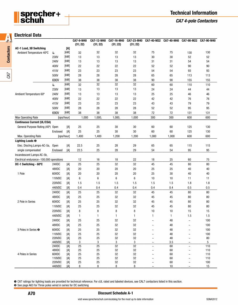
Electrical DataCA7-9-M40
(31; 22)CA7-12-M40
(31; 22)CA7-16-M40
(31; 22)CA7-23-M40
(31; 22)CA7-40-M22 CA7-40-M40 CA7-90-M22 CA7-90-M40
AC-1 Load, 3Ø Switching [A]Ambient Temperature 40ºC Ith [kW] 32 32 32 32 75 75 130 130
230V [kW] 13 13 13 13 30 30 52 52240V [kW] 13 13 13 13 31 31 54 54
400V [kW] 22 22 22 22 52 52 90 90
415V [kW] 23 23 23 23 54 54 93 93
500V [kW] 28 28 28 28 65 65 113 113
690V [kW] 38 38 38 38 90 90 155 155
Ith [kW] 32 32 32 32 60 60 110 110
230V [kW] 13 13 13 13 24 24 44 44
Ambient Temperature 60º 240V [kW] 13 13 13 13 25 25 46 46
400V [kW] 22 22 22 22 42 42 76 76
415V [kW] 23 23 23 23 43 43 79 79
500V [kW] 28 28 28 28 52 52 95 95
690V [kW] 38 38 38 38 72 72 131 131
Max Operating Rate [ops/hour] 1,000 1,000, 1,000, 1,000 300 300 600 600
Continuous Current (UL/CSA)
General Purpose Rating (40º) Open [A] 25 25 30 30 60 60 125 130
Enclosed [A] 25 25 30 30 60 60 125 130
Max. Operating Rate [ops/hour] 1,400 1,400 1,200 1,200 1,000 1,000 600 600
Lighting Loads ❶
Elec. Dischrg.Lamps-AC-5a, Open [A] 22.5 25 28 29 65 65 115 115
single compensated Enclosed [A] 22.5 25 28 29 54 54 95 95
Incandescent Lamps AC-5b,
Electrical endurance~100,000 operations 12 16 18 22 18 25 60 75
DC-1 Switching - 60ºC 24VDC [A] 25 25 32 32 45 45 80 80
48VDC [A] 20 20 20 20 25 25 40 40
1 Pole 60VDC [A] 20 20 20 20 25 30 40 40
110VDC [A] 6 6 6 6 10 10 11 11
220VDC [A] 1.5 1.5 1.5 1.5 1.5 1.5 1.8 1.8
440VDC [A] 0.4 0.4 0.4 0.4 0.4 0.4 0.5 0.5
24VDC [A] 25 25 32 32 45 45 80 80
48VDC [A] 25 25 32 32 45 45 80 80
2 Pole in Series 60VDC [A] 25 25 32 32 45 45 80 80
110VDC [A] 25 25 32 32 45 45 80 80
220VDC [A] 8 8 8 8 10 10 15 15
440VDC [A] 1 1 1 1 1 1 1.5 1.5
24VDC [A] 25 25 32 32 ~ 48 ~ 100
48VDC [A] 25 25 32 32 ~ 48 ~ 100
3 Poles in Series ➋ 60VDC [A] 25 25 32 32 ~ 48 ~ 100110VDC [A] 25 25 32 32 ~ 48 ~ 100220VDC [A] 25 25 32 32 ~ 48 ~ 80440VDC [A] 3 3 3 3 ~ 3.5 ~ 524VDC [A] 25 25 32 32 ~ 60 ~ 11048VDC [A] 25 25 32 32 ~ 60 ~ 110
4 Poles in Series 60VDC [A] 25 25 32 32 ~ 60 ~ 110110VDC [A] 25 25 32 32 ~ 60 ~ 110220VDC [A] 25 25 32 32 ~ 60 ~ 100440VDC [A] 8 8 8 8 ~ 10 ~ 15
Technical InformationCA7 4-pole Contactors
➊ CA7 ratings for lighting loads are provided for technical reference. For cUL rated and labeled devices, see CAL7 contactors listed in this section.➋See page A63 for Three poles wired in series for DC switching
A71
Cont
acto
rs
A
visit www.sprecherschuh.com/ecatalog for the most up to date informationSSNA2012
CA7
Discount Schedule A-1
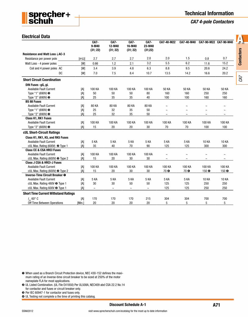
Electrical DataCA7-
9-M40 (31; 22)
CA7- 12-M40 (31; 22)
CA7-16-M40 (31; 22)
CA7- 23-M40 (31;22)
CA7-40-M22 CA7-40-M40 CA7-90-M22 CA7-90-M40
Resistance and Watt Loss Ie AC-3Resistance per power pole [mΩ] 2.7 2.7 2.7 2.0 2.0 1.5 0.8 0.7
Watt Loss - 4 power poles [W] 0.66 1.2 2.1 3.2 5.5 6.2 11.6 15.2
Coil and 4 power poles AC [W] 3.4 3.9 4.8 6.3 8.8 9.5 20.6 24.2
DC [W] 7.0 7.5 8.4 10.7 13.5 14.2 16.6 20.2
Technical InformationCA7 4-pole Contactors
➊ When used as a Branch Circuit Protection device, NEC 430-152 defines the maxi-mum rating of an Inverse-time circuit breaker to be sized at 250% of the motor nameplate FLA for most applications.
➋ UL Listed Combination. (UL File E41850) Per UL508A, NEC409 abd CSA 22.2 No.14 for contactor and fuses or circuit breaker only.
➌ Per IEC 60947-1 for contactor and fuses only.➍ UL Testing not complete a the time of printing this catalog.
Short Circuit CoordinationDIN Fuses -gG, gL
Available Fault Current [A] 100 KA 100 KA 100 KA 100 KA 50 KA 50 KA 50 KA 50 KAType “1” (690V) ➌ [A] 50 50 50 80 160 160 250 250Type “2” (690V) ➌ [A] 25 35 35 40 100 100 160 160
BS 88 FusesAvailable Fault Current [A] 80 KA 80 KA 80 KA 80 KA ~ ~ ~ ~Type “1” (690V) ➌ [A] 25 32 35 50 ~ ~ ~ ~Type “2” (690V) ➌ [A] 25 32 35 50 ~ ~ ~ ~
Class K1, RK1 FusesAvailable Fault Current [A] 100 KA 100 KA 100 KA 100 KA 100 KA 100 KA 100 KA 100 KAType “2” (600V) ➌ [A] 15 20 20 30 70 70 100 100
cUL Short-Circuit RatingsClass K1, RK1, K5, and RK5 Fuses
Available Fault Current [A] 5 KA 5 KA 5 KA 5 KA 5 KA 5 KA 10 KA 10 KAcUL Max. Rating (600V) ➋Type 1 [A] 35 40 70 90 125 125 300 300
Class CC & CSA HRCI FusesAvailable Fault Current [A] 100 KA 100 KA 100 KA 100 KA ~ ~ ~ ~cUL Max. Rating (600V) ➋Type 2 [A] 15 20 30 30 ~ ~ ~ ~
Class J CSA & HRCI-J FusesAvailable Fault Current [A] 100 KA 100 KA 100 KA 100 KA 100 KA 100 KA 100 KA 100 KAcUL Max. Rating (600V) ➋Type 2 [A] 15 20 30 30 70 ➍ 70 ➍ 150 ➍ 150 ➍
Inverse-Time Circuit Breaker ➊Available Fault Current [A] 5 KA 5 KA 5 KA 5 KA 5 KA 5 KA 10 KA 10 KAcUL Max. Rating 480V ➋Type 1 [A] 30 30 50 50 125 125 250 250cUL Max. Rating 600V ➋Type 1 [A] ~ ~ ~ ~ 125 125 250 250
Short Time Current Withstand RatingsIcw 60° C [A] 170 170 170 215 304 304 700 700Off Time Between Operations [Min.] 20 20 20 20 5 5 5 5
A72
Cont
acto
rs
A
visit www.sprecherschuh.com/ecatalog for the most up to date information SSNA2012
CA7
Discount Schedule A-1
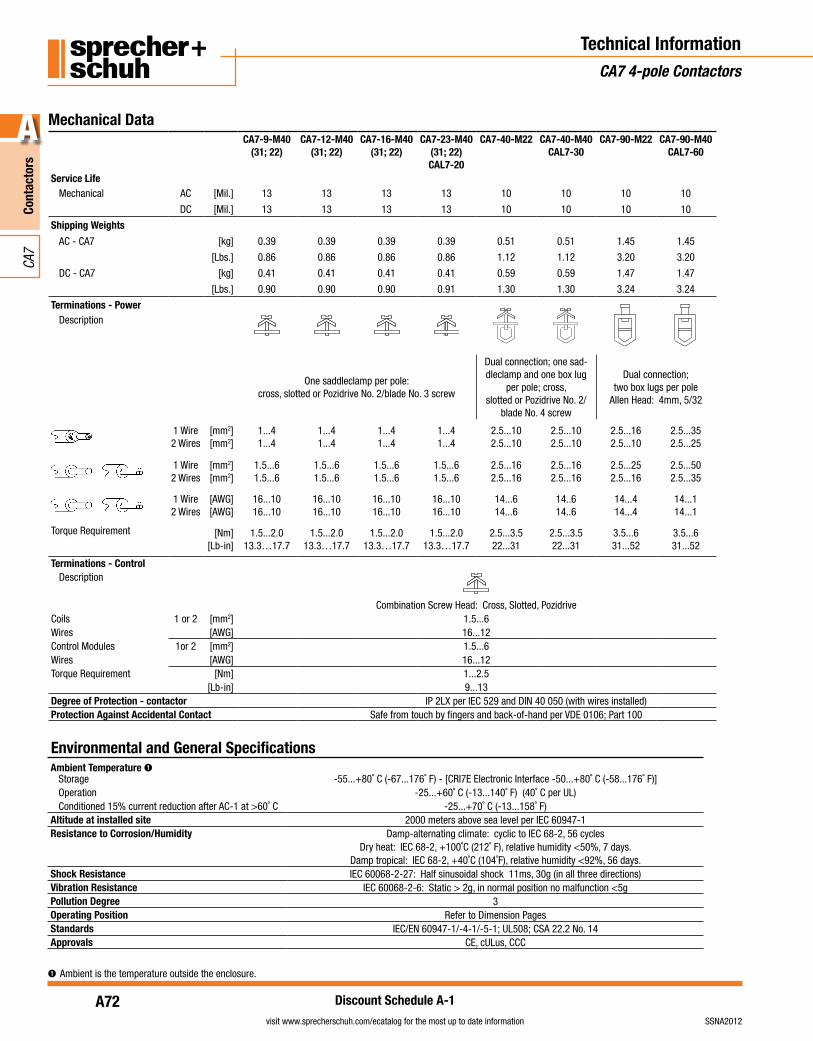
Mechanical DataCA7-9-M40
(31; 22)CA7-12-M40
(31; 22)CA7-16-M40
(31; 22)CA7-23-M40
(31; 22)CAL7-20
CA7-40-M22 CA7-40-M40CAL7-30
CA7-90-M22 CA7-90-M40CAL7-60
Service LifeMechanical AC [Mil.] 13 13 13 13 10 10 10 10
DC [Mil.] 13 13 13 13 10 10 10 10
Shipping Weights
AC - CA7 [kg] 0.39 0.39 0.39 0.39 0.51 0.51 1.45 1.45
[Lbs.] 0.86 0.86 0.86 0.86 1.12 1.12 3.20 3.20
DC - CA7 [kg] 0.41 0.41 0.41 0.41 0.59 0.59 1.47 1.47
[Lbs.] 0.90 0.90 0.90 0.91 1.30 1.30 3.24 3.24
Terminations - PowerDescription
One saddleclamp per pole:cross, slotted or Pozidrive No. 2/blade No. 3 screw
Dual connection; one sad-dleclamp and one box lug
per pole; cross,slotted or Pozidrive No. 2/
blade No. 4 screw
Dual connection; two box lugs per pole
Allen Head: 4mm, 5/32
1 Wire2 Wires
[mm2][mm2]
1...41...4
1...41...4
1...41...4
1...41...4
2.5...102.5...10
2.5...102.5...10
2.5...162.5...10
2.5...352.5...25
1 Wire2 Wires
[mm2][mm2]
1.5...61.5...6
1.5...61.5...6
1.5...61.5...6
1.5...61.5...6
2.5...162.5...16
2.5...162.5...16
2.5...252.5...16
2.5...502.5...35
1 Wire2 Wires
[AWG][AWG]
16...1016...10
16...1016...10
16...1016...10
16...1016...10
14...614...6
14..614..6
14...414...4
14...114...1
Torque Requirement [Nm][Lb-in]
1.5...2.013.3…17.7
1.5...2.013.3…17.7
1.5...2.013.3…17.7
1.5...2.013.3…17.7
2.5...3.522...31
2.5...3.522...31
3.5...631...52
3.5...631...52
Terminations - ControlDescription
Combination Screw Head: Cross, Slotted, PozidriveCoils 1 or 2 [mm2] 1.5...6Wires [AWG] 16...12Control Modules 1or 2 [mm2] 1.5...6Wires [AWG] 16...12Torque Requirement [Nm] 1...2.5
[Lb-in] 9...13Degree of Protection - contactor IP 2LX per IEC 529 and DIN 40 050 (with wires installed)Protection Against Accidental Contact Safe from touch by fingers and back-of-hand per VDE 0106; Part 100
Ambient Temperature ➊Storage -55...+80˚ C (-67...176˚ F) - [CRI7E Electronic Interface -50...+80˚ C (-58...176˚ F)]Operation -25...+60˚ C (-13...140˚ F) (40˚ C per UL)Conditioned 15% current reduction after AC-1 at >60˚ C -25...+70˚ C (-13...158˚ F)
Altitude at installed site 2000 meters above sea level per IEC 60947-1Resistance to Corrosion/Humidity Damp-alternating climate: cyclic to IEC 68-2, 56 cycles
Dry heat: IEC 68-2, +100˚C (212˚ F), relative humidity <50%, 7 days.Damp tropical: IEC 68-2, +40˚C (104˚F), relative humidity <92%, 56 days.
Shock Resistance IEC 60068-2-27: Half sinusoidal shock 11ms, 30g (in all three directions)Vibration Resistance IEC 60068-2-6: Static > 2g, in normal position no malfunction <5gPollution Degree 3Operating Position Refer to Dimension PagesStandards IEC/EN 60947-1/-4-1/-5-1; UL508; CSA 22.2 No. 14Approvals CE, cULus, CCC
Environmental and General Specifications
Technical InformationCA7 4-pole Contactors
➊ Ambient is the temperature outside the enclosure.

A73
Cont
acto
rs
A
visit www.sprecherschuh.com/ecatalog for the most up to date informationSSNA2012
CA7
Discount Schedule A-1
Technical InformationCA7 4-Pole Contactors
Coil Data - AC / Two Winding DCCA7-9-M40
(31; 22)CA7-12-M40
(31; 22)CA7-16-M40
(31; 22)CA7-23-M40
(31; 22)CAL7-20
CA7-40-M22 CA7-40-M40CAL7-30
CA7-90-M22 CA7-90-M40CAL7-60
Voltage RangeAC: 50Hz, 60Hz, 50/60 Hz Pickup [xUs] 0.85...1.1
Dropout [xUs] 0.3...0.6DC, Two Winding (90D) Pickup [xUs] 0.8...1.1 (9V coils = 0.65...1.3; 24V coils = 0.7...1.25)
Dropout [xUs] 0.1...0.6Coil Consumption
AC: 50Hz, 60Hz, 50/60 Hz Pickup [VA/W] 70/50 70/50 70/50 70/50 130/90 130/90 400/240 400/240Hold-in [VA/W] 8/2.6 8/2.6 8/2.6 9/3 12/3.6 12/3.6 24/9 24/9
DC: Two Winding (90D) Pickup [W] ~ ~ ~ ~ ~ ~ 325 325Hold-in [W] ~ ~ ~ ~ ~ ~ 5.5 5.5
Operating TimesAC: 50Hz, 60Hz, 50/60 Hz Pickup [ms] 15...30 15...30 15...30 15...30 15...30 15...30 20...30 20...40
Dropout [ms] 10...60 10...60 10...60 10...60 10...60 10...60 20...40 20...40with RC Suppressor Dropout [ms] 10...60 10...60 10...60 10...60 10...60 10...60 20...40 20...40
DC: Two Winding (90D) Pickup [ms] ~ ~ ~ ~ ~ ~ 15...20 15...25Dropout [ms] ~ ~ ~ ~ ~ ~ 20...25 15...25
Coil Data - Electronic DCVoltage Range Coil Consumption & Operating Times ➋Voltage Code
Nominal Voltage US[VDC]
Ratings[xUs]
Pickup [W] Hold-in [W] Dropout Voltage[xUs]
Pickup[ms]
Dropout[ms]CA7-9E…23E-M CA7-40E-M CA7-9E…23E-M CA7-40E-M
12E 12 0.7…1.25 17 24 1.7 2.5
0.3…0.4 20…50 20…5024E 24 0.7…1.25 17 24 1.7 2.548E 48…72 0.8…1.25 17 24 1.7 2.5110E 110…125 0.7…1.25 19 26 2 2.7220E 220…250 0.8…1.1 22 29 2.7 3.5
➊ The hold-in demand of the CA7-9E…43E is very low but the pick-up demand is approximately 1 ampere at 24 VDC. When sizing (dimen-sioning) a power supply for applications involving parallel switched contactors then multiply the peak demand by the number of contactors to be simultaneously switched and add to the hold-in demand of all other control circuit burdens, including other contactors, pilot devices, solenoids, etc.
A74
Cont
acto
rs
A
visit www.sprecherschuh.com/ecatalog for the most up to date information SSNA2012
CA7
Discount Schedule A-1
Technical InformationCA7 Contactors
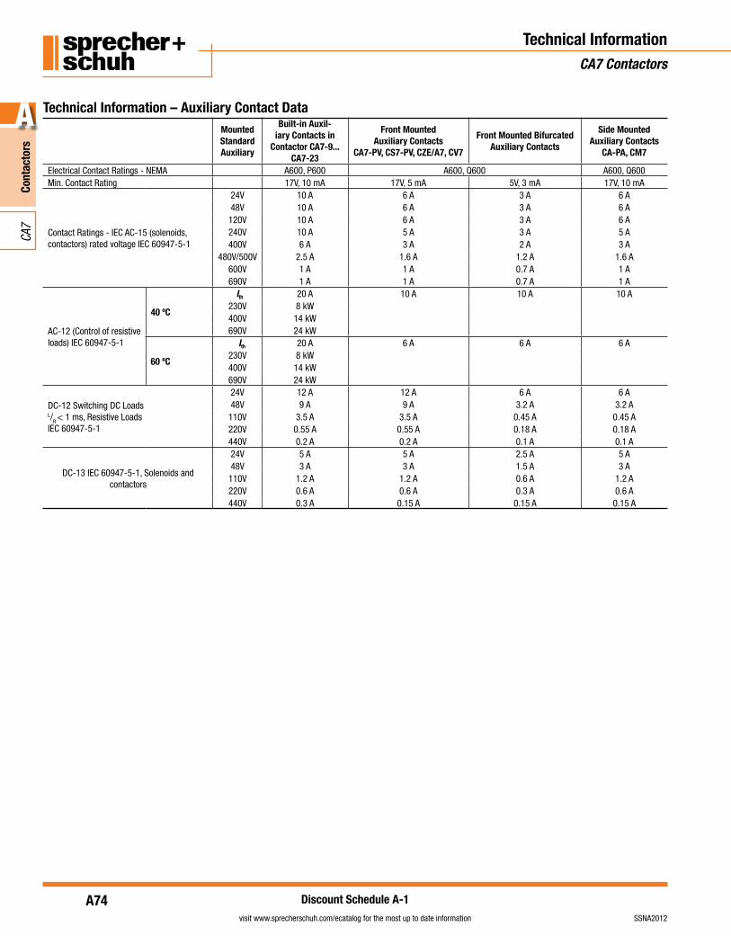
Technical Information – Auxiliary Contact DataMounted Standard Auxiliary
Built-in Auxil-iary Contacts in
Contactor CA7-9...CA7-23
Front Mounted Auxiliary Contacts
CA7-PV, CS7-PV, CZE/A7, CV7
Front Mounted Bifurcated Auxiliary Contacts
Side Mounted Auxiliary Contacts
CA-PA, CM7
Electrical Contact Ratings - NEMA A600, P600 A600, Q600 A600, Q600Min. Contact Rating 17V, 10 mA 17V, 5 mA 5V, 3 mA 17V, 10 mA
Contact Ratings - IEC AC-15 (solenoids,contactors) rated voltage IEC 60947-5-1
24V 10 A 6 A 3 A 6 A48V 10 A 6 A 3 A 6 A120V 10 A 6 A 3 A 6 A240V 10 A 5 A 3 A 5 A400V 6 A 3 A 2 A 3 A
480V/500V 2.5 A 1.6 A 1.2 A 1.6 A600V 1 A 1 A 0.7 A 1 A690V 1 A 1 A 0.7 A 1 A
AC-12 (Control of resistive loads) IEC 60947-5-1
40 ºC
Ith 20 A 10 A 10 A 10 A230V 8 kW400V 14 kW690V 24 kW
60 ºC
Ith 20 A 6 A 6 A 6 A230V 8 kW400V 14 kW690V 24 kW
DC-12 Switching DC LoadsL/R < 1 ms, Resistive Loads IEC 60947-5-1
24V 12 A 12 A 6 A 6 A48V 9 A 9 A 3.2 A 3.2 A110V 3.5 A 3.5 A 0.45 A 0.45 A220V 0.55 A 0.55 A 0.18 A 0.18 A440V 0.2 A 0.2 A 0.1 A 0.1 A
DC-13 IEC 60947-5-1, Solenoids and contactors
24V 5 A 5 A 2.5 A 5 A48V 3 A 3 A 1.5 A 3 A110V 1.2 A 1.2 A 0.6 A 1.2 A220V 0.6 A 0.6 A 0.3 A 0.6 A440V 0.3 A 0.15 A 0.15 A 0.15 A
A75
Cont
acto
rs
A
visit www.sprecherschuh.com/ecatalog for the most up to date informationSSNA2012
CA7
Discount Schedule A-1
Technical InformationCA7 Contactors
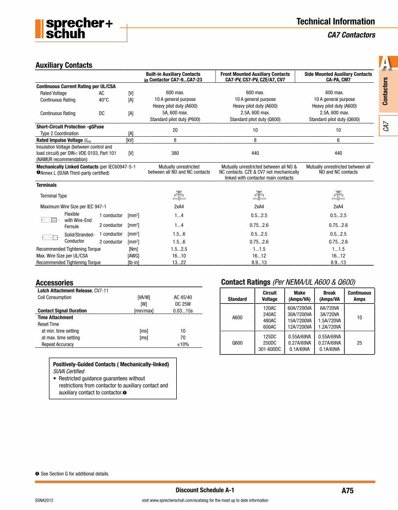
Built-in Auxiliary Contacts in Contactor CA7-9...CA7-23
Front Mounted Auxiliary Contacts CA7-PV, CS7-PV, CZE/A7, CV7
Side Mounted Auxiliary Contacts CA-PA, CM7
Continuous Current Rating per UL/CSARated Voltage AC [V] 600 max. 600 max. 600 max.Continuous Rating 40°C [A] 10 A general purpose 10 A general purpose 10 A general purpose
Heavy pilot duty (A600) Heavy pilot duty (A600) Heavy pilot duty (A600)Continuous Rating DC [A] 5A, 600 max. 2.5A, 600 max. 2.5A, 600 max.
Standard pilot duty (P600) Standard pilot duty (Q600) Standard pilot duty (Q600)Short-Circuit Protection -gGFuse
20 10 10Type 2 Coordination [A]
Rated Impulse Voltage Uimp [kV] 8 8 6Insulation Voltage (between control and load circuit) per DIN< VDE 0103, Part 101 (NAMUR recommendation)
[V] 380 440 440
Mechanically Linked Contacts (per IEC60947-5-1 ➊Annex L (SUVA Third-party certified)
Mutually unrestrictedbetween all NO and NC contacts
Mutually unrestricted between all NO & NC contacts. CZE & CV7 not mechanically
linked with contactor main contacts
Mutually unrestricted between all NO and NC contacts
Terminals
Terminal Type
Maximum Wire Size per IEC 947-1 2xA4 2xA4 2xA4Flexiblewith Wire-End Fernule
1 conductor [mm2] 1...4 0.5...2.5 0.5...2.5
2 conductor [mm2] 1...4 0.75...2.6 0.75...2.6
Solid/Stranded-Conductor
1 conductor [mm2] 1.5...6 0.5...2.5 0.5...2.5
2 conductor [mm2] 1.5...6 0.75...2.6 0.75...2.6Recommended Tightening Torque [Nm] 1.5...2.5 1...1.5 1...1.5Max. Wire Size per UL/CSA [AWG] 16...10 16...12 16...12Recommended Tightening Torque [lb-in] 13...22 8.9...13 8.9...13
Auxiliary Contacts
Latch Attachment Release, CV7-11Coil Consumption [VA/W] AC 45/40
[W] DC 25WContact Signal Duration [min/max] 0.03...15sTime AttachmentReset Time
at min. time setting [ms] 10at max. time setting [ms] 70Repeat Accuracy ±10%
Accessories
StandardCircuit Voltage
Make (Amps/VA)
Break (Amps/VA
Continuous Amps
A600
120AC240AC480AC600AC
60A/7200VA30A/7200VA15A/7200VA12A/7200VA
6A/720VA3A/720VA
1.5A/720VA1.2A/720VA
10
Q600125DC250DC
301-600DC
0.55A/69VA0.27A/69VA0.1A/69VA
0.55A/69VA0.27A/69VA0.1A/69VA
25
Contact Ratings (Per NEMA/UL A600 & Q600)
Positively-Guided Contacts ( Mechanically-linked)SUVA Certified• Restricted guidance guarantees without
restrictions from contactor to auxiliary contact and auxiliary contact to contactor.➊
➊ See Section G for additional details.
A76
Cont
acto
rs
A
visit www.sprecherschuh.com/ecatalog for the most up to date information SSNA2012
CA7
Discount Schedule A-1
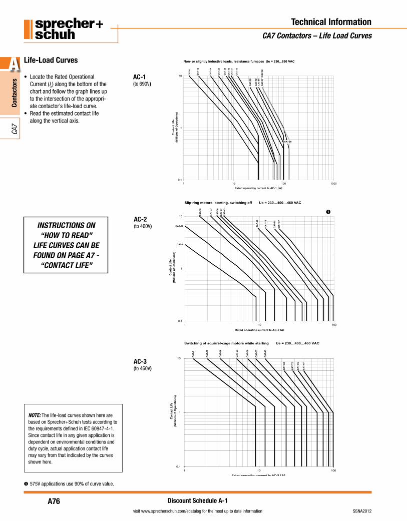
Technical InformationCA7 Contactors – Life Load Curves
Non- or slightly inductive loads, resistance furnaces Ue = 230...690 VAC
0.1
1
10
0001001011
Rated operating current Ie AC-1 [A]
Co
nta
ct L
ife
(Mill
ion
s o
f O
per
atio
ns)
CA
7-9
CA
7-12
CA
7-37
CA
7-23
CA
7-16
CA
7-60
CA
7-43
CA7-90
CA
7-40
CA
7-30
CA
7-72
CA
7-85
CA
7-97
/ C
A7-
90
Slip-ring motors: starting, switching off Ue = 230…400…460 VAC
0.1
1
10
001011
Rated operating current Ie AC-2 [A]
CA7-9
CA
7-85
CA
7-72
CA
7-60
CA
7-43
CA
7-37
CA
7-30
CA
7-23
CA
7-16
CA7-12 CA
7-97
Co
nta
ct L
ife
(Mill
ion
s o
f O
per
atio
ns)
➊ 575V applications use 90% of curve value.
NOTE: The life-load curves shown here are based on Sprecher+Schuh tests according to the requirements defined in IEC 60947-4-1. Since contact life in any given application is dependent on environmental conditions and duty cycle, actual application contact life may vary from that indicated by the curves shown here.
➊
Switching of squirrel-cage motors while starting Ue = 230…400…460 VAC
0.1
1
10
001011
Rated operating current Ie AC-3 [A]
CA
7-9
CA
7-12
CA
7-16
CA
7-23
CA
7-30
CA
7-37
CA
7-43
CA
7-60
CA
7-72
CA
7-85
CA
7-97
Con
tact
Life
(Mill
ions
of O
pera
tions
)
Life-Load Curves
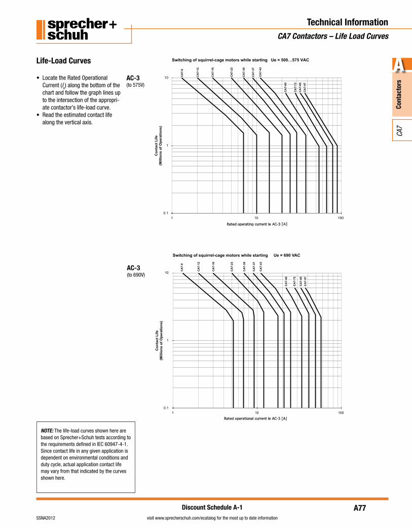
• Locate the Rated Operational Current (le) along the bottom of the chart and follow the graph lines up to the intersection of the appropri-ate contactor’s life-load curve.
• Read the estimated contact life along the vertical axis.
AC-1(to 690V)
AC-2(to 460V)
AC-3(to 460V)
INsTRUCTIONs ON “hOw TO READ”
LIfE CURvEs CAN bE fOUND ON PAGE A7 -
“CONTACT LIfE”
A77
Cont
acto
rs
A
visit www.sprecherschuh.com/ecatalog for the most up to date informationSSNA2012
CA7
Discount Schedule A-1
Technical InformationCA7 Contactors – Life Load Curves
NOTE: The life-load curves shown here are based on Sprecher+Schuh tests according to the requirements defined in IEC 60947-4-1. Since contact life in any given application is dependent on environmental conditions and duty cycle, actual application contact life may vary from that indicated by the curves shown here.
Switching of squirrel-cage motors while starting Ue = 500…575 VAC
0.1
1
10
001011
Rated operating current Ie AC-3 [A]
CA
7-9
CA
7-12
CA
7-16
CA
7-23
CA
7-30
CA
7-37
CA
7-60
CA
7-72
CA
7-85
CA
7-97
CA
7-43
Co
nta
ct L
ife
(Mill
ion
s o
f O
per
atio
ns)
Life-Load Curves
• Locate the Rated Operational Current (le) along the bottom of the chart and follow the graph lines up to the intersection of the appropri-ate contactor’s life-load curve.
• Read the estimated contact life along the vertical axis.
AC-3(to 575V)
Switching of squirrel-cage motors while starting Ue = 690 VAC
0.1
1
10
001011
Rated operational current Ie AC-3 [A]
CA
7-9
CA
7-12
CA
7-16
CA
7-23
CA
7-30
CA
7-37
CA
7-43
CA
7-60
CA
7-72
CA
7-85
CA
7-97
Co
nta
ct L
ife
(Mill
ion
s o
f O
per
atio
ns)
AC-3(to 690V)
A78
Cont
acto
rs
A
visit www.sprecherschuh.com/ecatalog for the most up to date information SSNA2012
CA7
Discount Schedule A-1
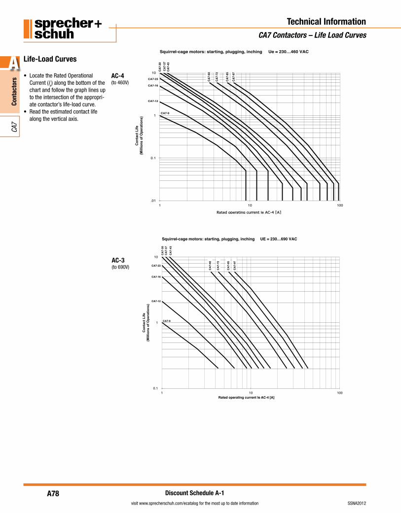
Life-Load Curves
• Locate the Rated Operational Current (le) along the bottom of the chart and follow the graph lines up to the intersection of the appropri-ate contactor’s life-load curve.
• Read the estimated contact life along the vertical axis.
AC-3 (to 690V)
Squirrel-cage motors: starting, plugging, inching Ue = 230…460 VAC
.01
0.1
1
10
001011
Rated operating current Ie AC-4 [A]
Co
nta
ct L
ife
(Mill
ion
s o
f O
per
atio
ns)
CA7-9
CA7-
85
CA7-
72
CA7-
60
CA7-
43CA
7-37
CA7-
30
CA7-23
CA7-16
CA7-12
CA7-
97
Squirrel-cage motors: starting, plugging, inching UE = 230…690 VAC
0.1
1
10
001011Rated operating current Ie AC-4 [A]
Co
nta
ct L
ife
(Mill
ion
s o
f O
per
atio
ns)
CA7-9
CA
7-43
CA
7-37
CA
7-30
CA7-23
CA7-16
CA7-12
CA
7-85
CA
7-60
CA
7-97
CA
7-72
Technical InformationCA7 Contactors – Life Load Curves
AC-4(to 460V)
A79
Cont
acto
rs
A
visit www.sprecherschuh.com/ecatalog for the most up to date informationSSNA2012
CA7
Discount Schedule A-1
Technical InformationCA7 Contactors – Life Load Curves
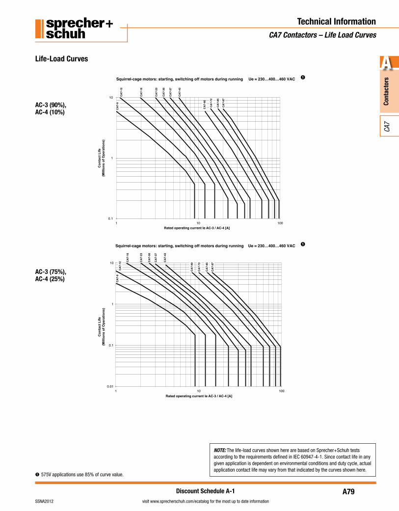
➊ 575V applications use 85% of curve value.
NOTE: The life-load curves shown here are based on Sprecher+Schuh tests according to the requirements defined in IEC 60947-4-1. Since contact life in any given application is dependent on environmental conditions and duty cycle, actual application contact life may vary from that indicated by the curves shown here.
Squirrel-cage motors: starting, switching off motors during running Ue = 230…400…460 VAC
0.1
1
10
001011Rated operating current Ie AC-3 / AC-4 [A]
Co
nta
ct L
ife
(Mill
ion
s o
f O
per
atio
ns)
CA
7-9
CA
7-85
CA
7-72
CA
7-60
CA
7-43
CA
7-37
CA
7-30
CA
7-23
CA
7-16
CA
7-12
CA
7-97
Life-Load Curves
AC-3 (90%),AC-4 (10%)
➊
Squirrel-cage motors: starting, switching off motors during running Ue = 230…400…460 VAC
0.01
0.1
1
10
001011Rated operating current Ie AC-3 / AC-4 [A]
Co
nta
ct L
ife
(Mill
ion
s o
f O
per
atio
ns)
CA
7-9
CA
7-85
CA
7-72
CA
7-60
CA
7-43
CA
7-37
CA
7-30
CA
7-23
CA
7-16
CA
7-12
CA
7-97
AC-3 (75%),AC-4 (25%)
➊
A80
Cont
acto
rs
A
visit www.sprecherschuh.com/ecatalog for the most up to date information SSNA2012
CA7
Discount Schedule A-1
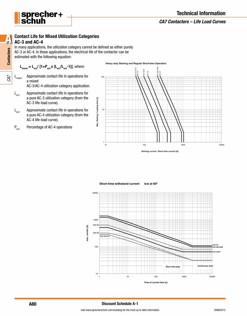
Contact Life for Mixed Utilization CategoriesAC-3 and AC-4In many applications, the utilization category cannot be defined as either purely AC-3 or AC-4. In those applications, the electrical life of the contactor can be estimated with the following equation:
Lmixed = Lac3/ [1+Pac4 x (Lac3/Lac4-1)], where:
Lmixed Approximate contact life in operations for a mixed AC-3/AC-4 utilization category application.
Lac3 Approximate contact life in operations for a pure AC-3 utilization category (from the AC-3 life-load curve).
Lac4 Approximate contact life in operations for a pure AC-4 utilization category (from the AC-4 life-load curve).
Pac4 Percentage of AC-4 operations
Heavy duty Starting and Regular Short-time Operation
1
10
100
00001000100101
Starting current / Short time current [A]
Max
. Sta
rtin
g /
Lo
adin
g t
ime
[s]
CA
7-9/
12/1
6C
A7-
23
CA
7-30
/37
CA
7-43
CA
7-60
/72/
85
CA
7-97
Short-time withstand current Icw at 60º
10
100
1000
10000
000010001001011
Time of current flow [s]
max
. cur
rent
[A]
Short time duty Continuous duty
CA7-9/12/16
CA7-23
CA7-30/37
CA7-43
CA7-60/72/85CA7-97
Technical InformationCA7 Contactors – Life Load Curves
A81
Cont
acto
rs
A
visit www.sprecherschuh.com/ecatalog for the most up to date informationSSNA2012
CA7
Discount Schedule A-1
Technical InformationCA7 Contactors – Operating Rates
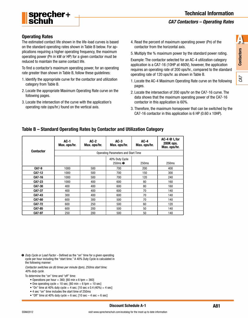
Operating RatesThe estimated contact life shown in the life-load curves is based on the standard operating rates shown in Table B below. For ap-plications requiring a higher operating frequency, the maximum operating power (Pn in kW or HP) for a given contactor must be reduced to maintain the same contact life.
To find a contactor’s maximum operating power, for an operating rate greater than shown in Table B, follow these guidelines:
1. Identify the appropriate curve for the contactor and utilization category from Table B.
2. Locate the appropriate Maximum Operating Rate curve on the following pages.
3. Locate the intersection of the curve with the application’s operating rate (ops/hr.) found on the vertical axis.
4. Read the percent of maximum operating power (Pn) of the contactor from the horizontal axis.
5. Multiply the % maximum power by the standard power rating.
Example: The contactor selected for an AC-4 utilization category application is a CA7-16 (10HP at 460V), however, the application requires an operating rate of 200 ops/hr., compared to the standard operating rate of 120 ops/hr. as shown in Table B.
1. Locate the AC-4 Maximum Operating Rate curve on the following pages.
2. Locate the intersection of 200 ops/hr on the CA7-16 curve. The data shows that the maximum operating power of the CA7-16 contactor in this application is 60%.
3. Therefore, the maximum horsepower that can be switched by the CA7-16 contactor in this application is 6 HP (0.60 x 10HP).
Table B – Standard Operating Rates by Contactor and Utilization Category
➊ Duty Cycle or Load Factor – Defined as the “on” time for a given operating cycle per hour including the “start time.” A 40% Duty Cycle is calculated in the following manner:
Contactor switches six (6) times per minute (tpm), 250ms start time; 40% duty cycle.
To determine the “on” time and “off” time: • Operations per hour = 360; [60 min x 6 tpm = 360] • One operating cycle = 10 sec; [60 min ÷ 6 tpm = 10 sec] • “On” time at 40% duty cycle = 4 sec; [10 sec x 0.4 (40%) = 4 sec] • 4 sec “on” time includes the start time of 250ms • “Off” time at 40% duty cycle = 6 sec; [10 sec – 4 sec = 6 sec]
Contactor
AC-1Max. ops/hr.
AC-2Max. ops/hr.
AC-3Max. ops/hr.
AC-4Max. ops/hr.
AC-4 @ Ie for 200K ops.
Max. ops/hr.
Operating Parameters and Start Time
40% Duty Cycle 250ms ➊ 250ms 250ms
CA7-9 1000 500 700 200 400CA7-12 1000 500 700 150 300CA7-16 1000 500 700 120 240CA7-23 1000 400 600 80 160CA7-30 400 400 600 80 160CA7-37 400 400 600 70 140CA7-43 300 400 600 70 140CA7-60 600 300 500 70 140CA7-72 600 250 500 60 120CA7-85 600 200 500 50 140CA7-97 250 200 500 50 140
A82
Cont
acto
rs
A
visit www.sprecherschuh.com/ecatalog for the most up to date information SSNA2012
CA7
Discount Schedule A-1
Technical InformationCA7 Contactors – Operating Rates
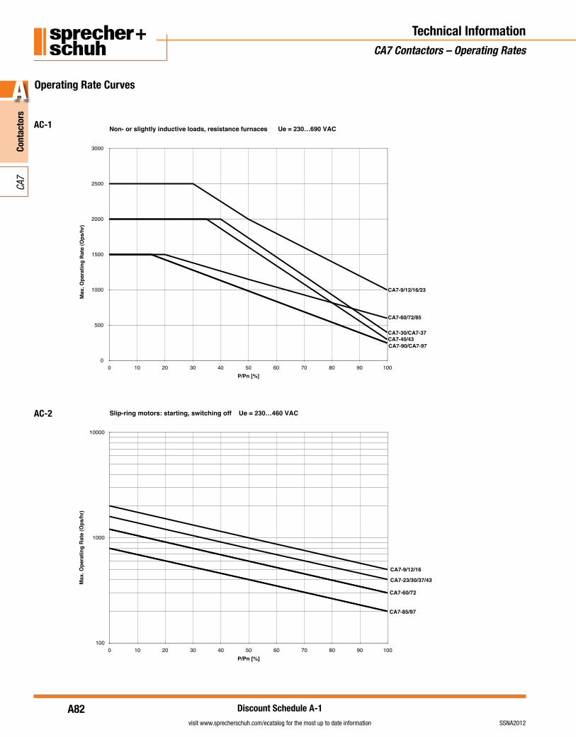
Non- or slightly inductive loads, resistance furnaces Ue = 230…690 VAC
0
500
1000
1500
2000
2500
3000
0 10 20 30 40 50 60 70 80 90 100P/Pn [%]
Max
. Ope
ratin
g R
ate
(Ops
/hr)
CA7-9/12/16/23
CA7-30/CA7-37CA7-40/43
CA7-60/72/85
CA7-90/CA7-97
Slip-ring motors: starting, switching off Ue = 230…460 VAC
100
1000
10000
0 10 20 30 40 50 60 70 80 90 100P/Pn [%]
Max
. Ope
ratin
g Ra
te (O
ps/h
r)
AC2
CA7-9/12/16
CA7-23/30/37/43
CA7-60/72
CA7-85/97
Operating Rate Curves
AC-1
AC-2
A83
Cont
acto
rs
A
visit www.sprecherschuh.com/ecatalog for the most up to date informationSSNA2012
CA7
Discount Schedule A-1
Technical InformationCA7 Contactors – Operating Rates
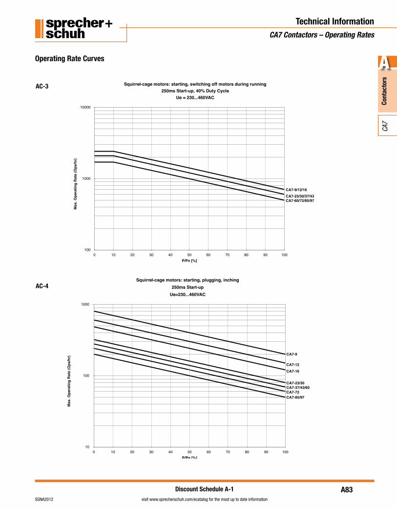
Operating Rate Curves
AC-3
AC-4
Squirrel-cage motors: starting, switching off motors during running250ms Start-up, 40% Duty Cycle
100
1000
10000
0 10 20 30 40 50 60 70 80 90 100P/Pn [%]
Max
. Ope
ratin
g R
ate
(Ops
/hr)
Ue = 230...460VAC
CA7-9/12/16CA7-23/30/37/43CA7-60/72/85/97
Squirrel-cage motors: starting, plugging, inching250ms Start-up
10
100
1000
0 10 20 30 40 50 60 70 80 90 100P/Pn [%]
Max
. Ope
ratin
g R
ate
(Ops
/hr)
Ue=230...460VAC
CA7-9
CA7-12
CA7-23/30CA7-37/43/60
CA7-85/97
CA7-16
CA7-72
A84
Cont
acto
rs
A
visit www.sprecherschuh.com/ecatalog for the most up to date information SSNA2012
CA7
Discount Schedule A-1
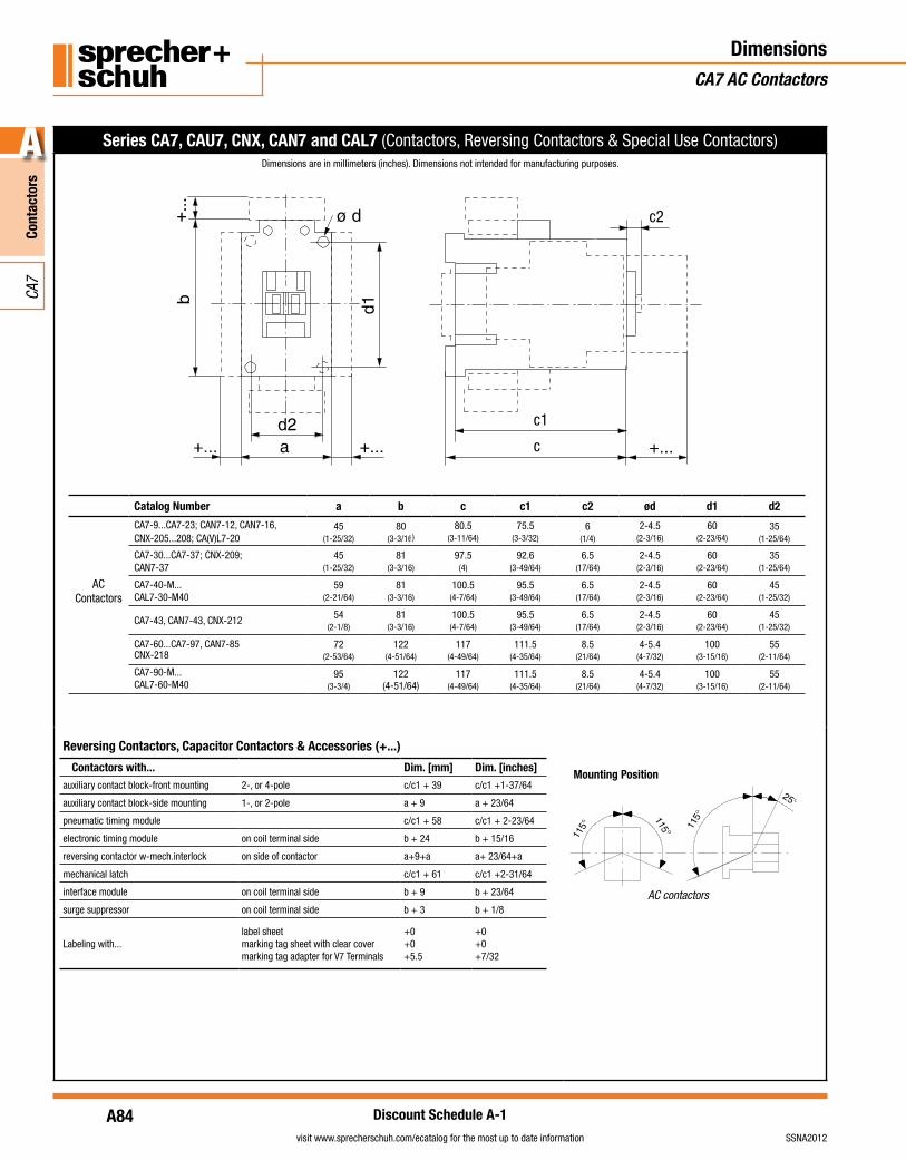
DimensionsCA7 AC Contactors
Series CA7, CAU7, CNX, CAN7 and CAL7 (Contactors, Reversing Contactors & Special Use Contactors)Dimensions are in millimeters (inches). Dimensions not intended for manufacturing purposes.
Catalog Number a b c c1 c2 ød d1 d2
ACContactors
CA7-9...CA7-23; CAN7-12, CAN7-16,CNX-205...208; CA(V)L7-20
45(1-25/32)
80(3-3/16)
80.5(3-11/64)
75.5(3-3/32)
6(1/4)
2-4.5(2-3/16)
60(2-23/64)
35(1-25/64)
CA7-30...CA7-37; CNX-209; CAN7-37
45(1-25/32)
81(3-3/16)
97.5(4)
92.6(3-49/64)
6.5(17/64)
2-4.5(2-3/16)
60(2-23/64)
35(1-25/64)
CA7-40-M...CAL7-30-M40
59(2-21/64)
81(3-3/16)
100.5(4-7/64)
95.5(3-49/64)
6.5(17/64)
2-4.5(2-3/16)
60(2-23/64)
45(1-25/32)
CA7-43, CAN7-43, CNX-212 54(2-1/8)
81(3-3/16)
100.5(4-7/64)
95.5(3-49/64)
6.5(17/64)
2-4.5(2-3/16)
60(2-23/64)
45(1-25/32)
CA7-60...CA7-97, CAN7-85CNX-218
72(2-53/64)
122(4-51/64)
117(4-49/64)
111.5(4-35/64)
8.5(21/64)
4-5.4(4-7/32)
100(3-15/16)
55(2-11/64)
CA7-90-M...CAL7-60-M40
95(3-3/4)
122(4-51/64)
117(4-49/64)
111.5(4-35/64)
8.5(21/64)
4-5.4(4-7/32)
100(3-15/16)
55(2-11/64)
Reversing Contactors, Capacitor Contactors & Accessories (+...)
Contactors with... Dim. [mm] Dim. [inches]auxiliary contact block-front mounting 2-, or 4-pole c/c1 + 39 c/c1 +1-37/64
auxiliary contact block-side mounting 1-, or 2-pole a + 9 a + 23/64
pneumatic timing module c/c1 + 58 c/c1 + 2-23/64
electronic timing module on coil terminal side b + 24 b + 15/16
reversing contactor w-mech.interlock on side of contactor a+9+a a+ 23/64+a
mechanical latch c/c1 + 61 c/c1 +2-31/64
interface module on coil terminal side b + 9 b + 23/64
surge suppressor on coil terminal side b + 3 b + 1/8
Labeling with...label sheetmarking tag sheet with clear covermarking tag adapter for V7 Terminals
+0+0+5.5
+0+0+7/32
Mounting Position
AC contactors
A85
Cont
acto
rs
A
visit www.sprecherschuh.com/ecatalog for the most up to date informationSSNA2012
CA7
Discount Schedule A-1
DimensionsCA7 DC Contactors
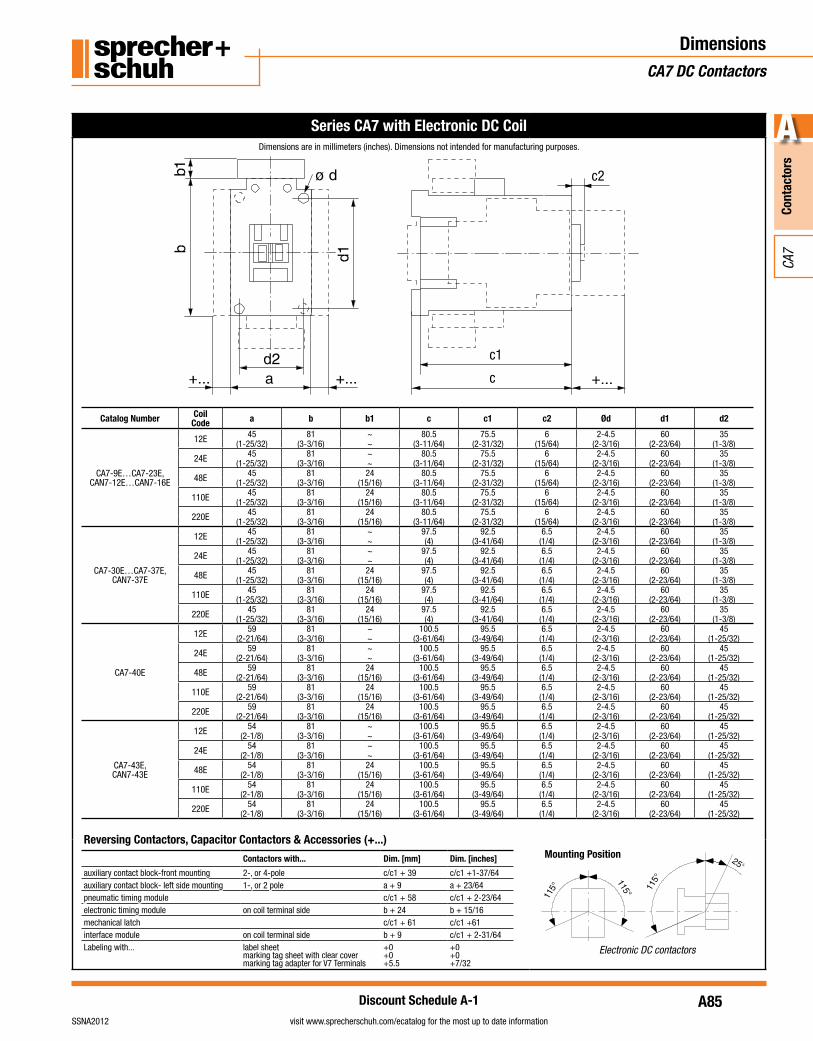
Series CA7 with Electronic DC CoilDimensions are in millimeters (inches). Dimensions not intended for manufacturing purposes.
Reversing Contactors, Capacitor Contactors & Accessories (+...)
Contactors with... Dim. [mm] Dim. [inches]
auxiliary contact block-front mounting 2-, or 4-pole c/c1 + 39 c/c1 +1-37/64auxiliary contact block- left side mounting 1-, or 2 pole a + 9 a + 23/64pneumatic timing module c/c1 + 58 c/c1 + 2-23/64electronic timing module on coil terminal side b + 24 b + 15/16mechanical latch c/c1 + 61 c/c1 +61interface module on coil terminal side b + 9 c/c1 + 2-31/64Labeling with... label sheet
marking tag sheet with clear covermarking tag adapter for V7 Terminals
+0+0+5.5
+0+0+7/32
Mounting Position
Electronic DC contactors
Catalog Number Coil Code a b b1 c c1 c2 Ød d1 d2
CA7-9E…CA7-23E,CAN7-12E…CAN7-16E
12E 45 81 ~ 80.5 75.5 6 2-4.5 60 35(1-25/32) (3-3/16) ~ (3-11/64) (2-31/32) (15/64) (2-3/16) (2-23/64) (1-3/8)
24E 45 81 ~ 80.5 75.5 6 2-4.5 60 35(1-25/32) (3-3/16) ~ (3-11/64) (2-31/32) (15/64) (2-3/16) (2-23/64) (1-3/8)
48E 45 81 24 80.5 75.5 6 2-4.5 60 35(1-25/32) (3-3/16) (15/16) (3-11/64) (2-31/32) (15/64) (2-3/16) (2-23/64) (1-3/8)
110E 45 81 24 80.5 75.5 6 2-4.5 60 35(1-25/32) (3-3/16) (15/16) (3-11/64) (2-31/32) (15/64) (2-3/16) (2-23/64) (1-3/8)
220E 45 81 24 80.5 75.5 6 2-4.5 60 35(1-25/32) (3-3/16) (15/16) (3-11/64) (2-31/32) (15/64) (2-3/16) (2-23/64) (1-3/8)
CA7-30E…CA7-37E,CAN7-37E
12E 45 81 ~ 97.5 92.5 6.5 2-4.5 60 35(1-25/32) (3-3/16) ~ (4) (3-41/64) (1/4) (2-3/16) (2-23/64) (1-3/8)
24E 45 81 ~ 97.5 92.5 6.5 2-4.5 60 35(1-25/32) (3-3/16) ~ (4) (3-41/64) (1/4) (2-3/16) (2-23/64) (1-3/8)
48E 45 81 24 97.5 92.5 6.5 2-4.5 60 35(1-25/32) (3-3/16) (15/16) (4) (3-41/64) (1/4) (2-3/16) (2-23/64) (1-3/8)
110E 45 81 24 97.5 92.5 6.5 2-4.5 60 35(1-25/32) (3-3/16) (15/16) (4) (3-41/64) (1/4) (2-3/16) (2-23/64) (1-3/8)
220E 45 81 24 97.5 92.5 6.5 2-4.5 60 35(1-25/32) (3-3/16) (15/16) (4) (3-41/64) (1/4) (2-3/16) (2-23/64) (1-3/8)
CA7-40E
12E 59 81 ~ 100.5 95.5 6.5 2-4.5 60 45(2-21/64) (3-3/16) ~ (3-61/64) (3-49/64) (1/4) (2-3/16) (2-23/64) (1-25/32)
24E 59 81 ~ 100.5 95.5 6.5 2-4.5 60 45(2-21/64) (3-3/16) ~ (3-61/64) (3-49/64) (1/4) (2-3/16) (2-23/64) (1-25/32)
48E 59 81 24 100.5 95.5 6.5 2-4.5 60 45(2-21/64) (3-3/16) (15/16) (3-61/64) (3-49/64) (1/4) (2-3/16) (2-23/64) (1-25/32)
110E 59 81 24 100.5 95.5 6.5 2-4.5 60 45(2-21/64) (3-3/16) (15/16) (3-61/64) (3-49/64) (1/4) (2-3/16) (2-23/64) (1-25/32)
220E 59 81 24 100.5 95.5 6.5 2-4.5 60 45(2-21/64) (3-3/16) (15/16) (3-61/64) (3-49/64) (1/4) (2-3/16) (2-23/64) (1-25/32)
CA7-43E,CAN7-43E
12E 54 81 ~ 100.5 95.5 6.5 2-4.5 60 45(2-1/8) (3-3/16) ~ (3-61/64) (3-49/64) (1/4) (2-3/16) (2-23/64) (1-25/32)
24E 54 81 ~ 100.5 95.5 6.5 2-4.5 60 45(2-1/8) (3-3/16) ~ (3-61/64) (3-49/64) (1/4) (2-3/16) (2-23/64) (1-25/32)
48E 54 81 24 100.5 95.5 6.5 2-4.5 60 45(2-1/8) (3-3/16) (15/16) (3-61/64) (3-49/64) (1/4) (2-3/16) (2-23/64) (1-25/32)
110E 54 81 24 100.5 95.5 6.5 2-4.5 60 45(2-1/8) (3-3/16) (15/16) (3-61/64) (3-49/64) (1/4) (2-3/16) (2-23/64) (1-25/32)
220E 54 81 24 100.5 95.5 6.5 2-4.5 60 45(2-1/8) (3-3/16) (15/16) (3-61/64) (3-49/64) (1/4) (2-3/16) (2-23/64) (1-25/32)
A86
Cont
acto
rs
A
visit www.sprecherschuh.com/ecatalog for the most up to date information SSNA2012
CA7
Discount Schedule A-1
DimensionsCA7 DC Contactors
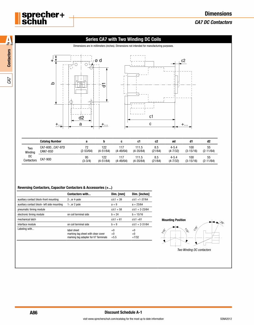
Series CA7 with Two Winding DC CoilsDimensions are in millimeters (inches). Dimensions not intended for manufacturing purposes.
Catalog Number a b c c1 c2 ød d1 d2
Two Winding
DCContactors
CA7-60D...CA7-97DCAN7-85D
72(2-53/64)
122(4-51/64)
117(4-49/64)
111.5(4-35/64)
8.5(21/64)
4-5.4(4-7/32)
100(3-15/16)
55(2-11/64)
CA7-90D95
(3-3/4)122
(4-51/64)117
(4-49/64)111.5
(4-35/64)8.5
(21/64)4-5.4
(4-7/32)100
(3-15/16)55
(2-11/64)
Reversing Contactors, Capacitor Contactors & Accessories (+...)
Contactors with... Dim. [mm] Dim. [inches]
auxiliary contact block-front mounting 2-, or 4-pole c/c1 + 39 c/c1 +1-37/64
auxiliary contact block- left side mounting 1-, or 2 pole a + 9 a + 23/64
pneumatic timing module c/c1 + 58 c/c1 + 2-23/64
electronic timing module on coil terminal side b + 24 b + 15/16
mechanical latch c/c1 + 61 c/c1 +61
interface module on coil terminal side b + 9 c/c1 + 2-31/64
Labeling with... label sheetmarking tag sheet with clear covermarking tag adapter for V7 Terminals
+0+0+5.5
+0+0+7/32
Mounting Position
Two Winding DC contactors
A87
Cont
acto
rs
A
visit www.sprecherschuh.com/ecatalog for the most up to date informationSSNA2012
CA7
Discount Schedule A-1
DimensionsCA7 Contactors
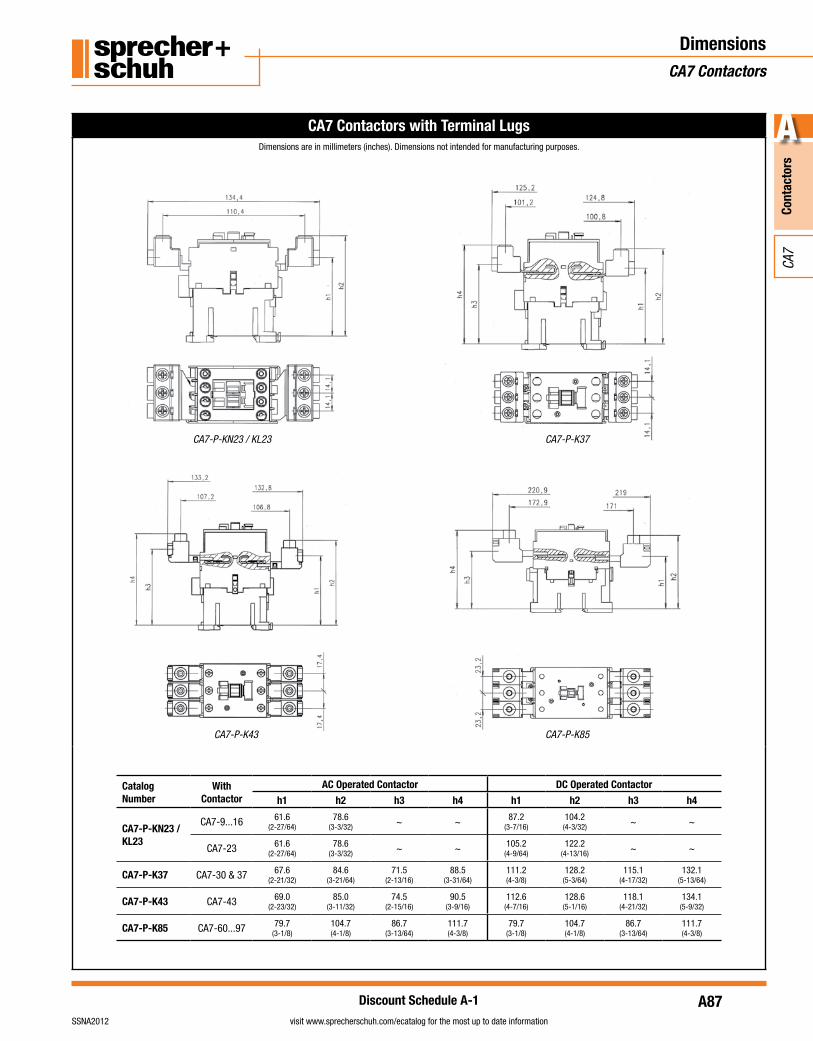
CA7 Contactors with Terminal LugsDimensions are in millimeters (inches). Dimensions not intended for manufacturing purposes.
CA7-P-KN23 / KL23 CA7-P-K37
CA7-P-K43 CA7-P-K85
CatalogNumber
WithContactor
AC Operated Contactor DC Operated Contactor
h1 h2 h3 h4 h1 h2 h3 h4
CA7-P-KN23 / KL23
CA7-9...16 61.6(2-27/64)
78.6(3-3/32) ~ ~ 87.2
(3-7/16)104.2
(4-3/32) ~ ~
CA7-23 61.6(2-27/64)
78.6(3-3/32) ~ ~ 105.2
(4-9/64)122.2
(4-13/16) ~ ~
CA7-P-K37 CA7-30 & 37 67.6(2-21/32)
84.6(3-21/64)
71.5(2-13/16)
88.5(3-31/64)
111.2(4-3/8)
128.2(5-3/64)
115.1(4-17/32)
132.1(5-13/64)
CA7-P-K43 CA7-43 69.0(2-23/32)
85.0(3-11/32)
74.5(2-15/16)
90.5(3-9/16)
112.6(4-7/16)
128.6(5-1/16)
118.1(4-21/32)
134.1(5-9/32)
CA7-P-K85 CA7-60...97 79.7(3-1/8)
104.7(4-1/8)
86.7(3-13/64)
111.7(4-3/8)
79.7(3-1/8)
104.7(4-1/8)
86.7(3-13/64)
111.7(4-3/8)
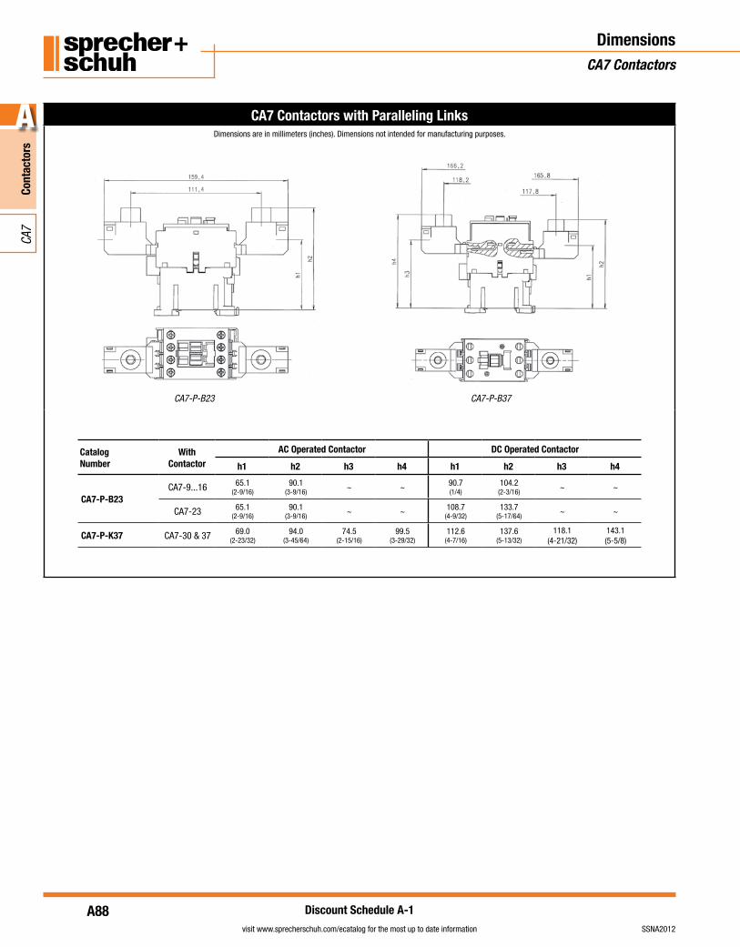
A88
Cont
acto
rs
A
visit www.sprecherschuh.com/ecatalog for the most up to date information SSNA2012
CA7
Discount Schedule A-1
DimensionsCA7 Contactors
CA7 Contactors with Paralleling LinksDimensions are in millimeters (inches). Dimensions not intended for manufacturing purposes.
CA7-P-B23 CA7-P-B37
CatalogNumber
WithContactor
AC Operated Contactor DC Operated Contactor
h1 h2 h3 h4 h1 h2 h3 h4
CA7-P-B23CA7-9...16 65.1
(2-9/16)90.1
(3-9/16)~ ~ 90.7
(1/4)104.2
(2-3/16)~ ~
CA7-23 65.1(2-9/16)
90.1(3-9/16)
~ ~ 108.7(4-9/32)
133.7(5-17/64)
~ ~
CA7-P-K37 CA7-30 & 37 69.0(2-23/32)
94.0(3-45/64)
74.5(2-15/16)
99.5(3-29/32)
112.6(4-7/16)
137.6(5-13/32)
118.1(4-21/32)
143.1(5-5/8)
A89
Cont
acto
rs
A
visit www.sprecherschuh.com/ecatalog for the most up to date informationSSNA2012
CA7
Discount Schedule A-1
DimensionsCA7 Contactors
Notes


![CA7-33-Commands [Wazhua.Com]](https://img.pdfslide.us/doc/110x75/543d7ed7afaf9fa80a8b48a9/ca7-33-commands-wazhuacom.jpg)


![CA7-9 CA7-12 CA7-16 CA7-23 CA7-30 CA7-37 CA7-43 CA7 · PDF file250 250 220 200 200 200 200 200 120 120 120 120 Wye-Delta (Star Delta) 230V [kW] 5.5 7.5 10 13 17 20 22 30 32 37 45 50](https://img.pdfslide.us/doc/110x75/5ab8c0747f8b9ad13d8ce249/ca7-9-ca7-12-ca7-16-ca7-23-ca7-30-ca7-37-ca7-43-ca7-250-220-200-200-200-200.jpg)