Embed Size (px)
Citation preview
IOM-F -DC/DCDA
I N S T A L L A T I O N , O P E R A T I O N , M A I N T E N A N C E
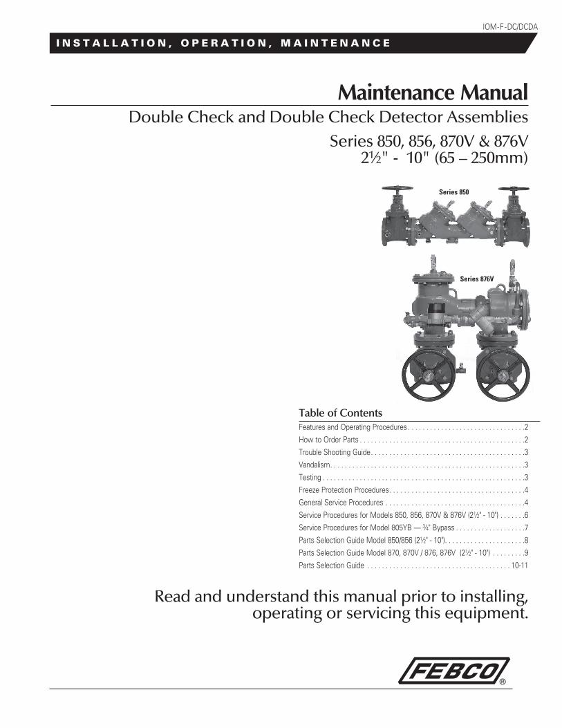
Maintenance ManualDouble Check and Double Check Detector Assemblies
Series 850, 856, 870V & 876V 21⁄2" - 10" (65 – 250mm)
Read and understand this manual prior to installing, operating or servicing this equipment.
Table of ContentsFeatures and Operating Procedures . . . . . . . . . . . . . . . . . . . . . . . . . . . . . . . .2
How to Order Parts . . . . . . . . . . . . . . . . . . . . . . . . . . . . . . . . . . . . . . . . . . . . .2
Trouble Shooting Guide . . . . . . . . . . . . . . . . . . . . . . . . . . . . . . . . . . . . . . . . . .3
Vandalism . . . . . . . . . . . . . . . . . . . . . . . . . . . . . . . . . . . . . . . . . . . . . . . . . . . . .3
Testing . . . . . . . . . . . . . . . . . . . . . . . . . . . . . . . . . . . . . . . . . . . . . . . . . . . . . . .3
Freeze Protection Procedures . . . . . . . . . . . . . . . . . . . . . . . . . . . . . . . . . . . . .4
General Service Procedures . . . . . . . . . . . . . . . . . . . . . . . . . . . . . . . . . . . . . .4
Service Procedures for Models 850, 856, 870V & 876V (21⁄2" - 10") . . . . . . .6
Service Procedures for Model 805YB — 3⁄4" Bypass . . . . . . . . . . . . . . . . . . .7
Parts Selection Guide Model 850/856 (21⁄2" - 10") . . . . . . . . . . . . . . . . . . . . . .8
Parts Selection Guide Model 870, 870V / 876, 876V (21⁄2" - 10") . . . . . . . . .9
Parts Selection Guide . . . . . . . . . . . . . . . . . . . . . . . . . . . . . . . . . . . . . . . 10-11
Series 850
Series 876V
2
Feature and Operating Procedures
MAINTENANCE MANUAL SERIES 850, 856, 870V & 876V 21⁄2"- 10" (65 – 250mm)
Double Check Valve Assembly OperationThe FEBCO Double Check Valve Assemblies consist of two indepen-dently operating, spring loaded check valves . The pressure drop across the first check valve is approximately 1 .0 psig with no flow . The pressure drop across the second check valve is also 1 .0 psig with no flow .
A complete assembly includes two shutoff valves and four test cocks . NOTE: The 870V and 876V, when installed in the vertical orientation, must include vertical support under the second check body section .
Double Check Detector Assemblies Bypass OperationAll low flow demands up to a minimum of three GPM are to pass only through the bypass assembly .
All flows above three GPM will pass through both the bypass and main-line valve without accurate meter registration .
How to Order Parts/Repair Kits1) Locate item number and kit number in this maintenance manual .
2) Verify the size of the valve the parts are to be used on .
3) Provide full model number located on I .D . plate .
4) Give kit number .
5) A serial number (located on the I .D . plate) will assist in ordering the proper kits .
6) Contact your local FEBCO Parts Distributor .
3
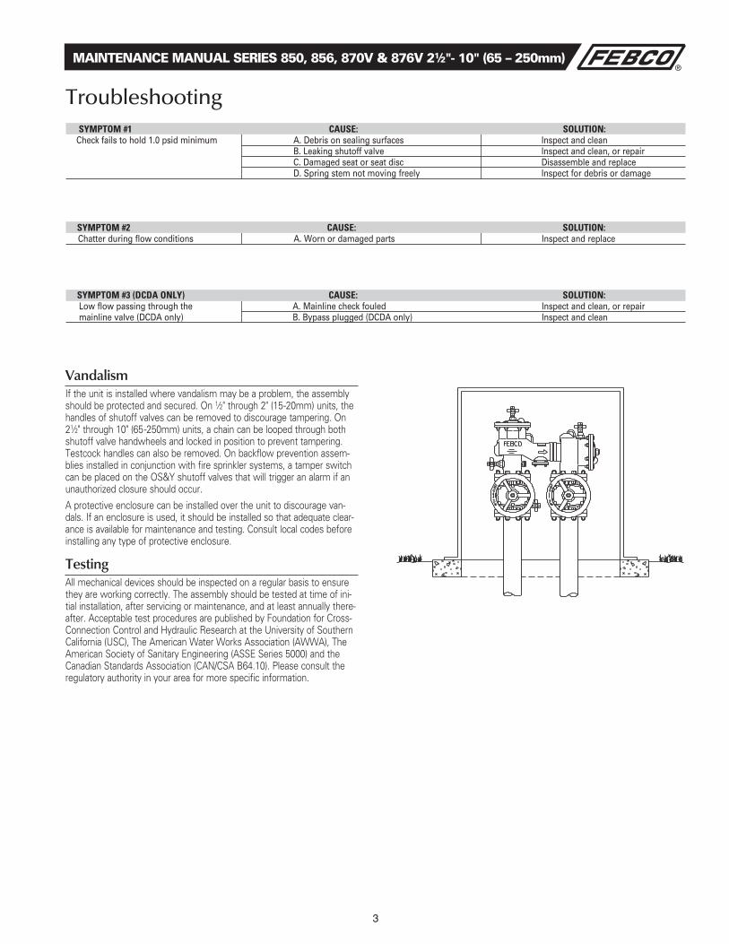
VandalismIf the unit is installed where vandalism may be a problem, the assembly should be protected and secured . On 1⁄2" through 2" (15-20mm) units, the handles of shutoff valves can be removed to discourage tampering . On 21⁄2" through 10" (65-250mm) units, a chain can be looped through both shutoff valve handwheels and locked in position to prevent tampering . Testcock handles can also be removed . On backflow prevention assem-blies installed in conjunction with fire sprinkler systems, a tamper switch can be placed on the OS&Y shutoff valves that will trigger an alarm if an unauthorized closure should occur .
A protective enclosure can be installed over the unit to discourage van-dals . If an enclosure is used, it should be installed so that adequate clear-ance is available for maintenance and testing . Consult local codes before installing any type of protective enclosure .
TestingAll mechanical devices should be inspected on a regular basis to ensure they are working correctly . The assembly should be tested at time of ini-tial installation, after servicing or maintenance, and at least annually there-after . Acceptable test procedures are published by Foundation for Cross-Connection Control and Hydraulic Research at the University of Southern California (USC), The American Water Works Association (AWWA), The American Society of Sanitary Engineering (ASSE Series 5000) and the Canadian Standards Association (CAN/CSA B64 .10) . Please consult the regulatory authority in your area for more specific information .
MAINTENANCE MANUAL SERIES 850, 856, 870V & 876V 21⁄2"- 10" (65 – 250mm)
Troubleshooting Symptom #1 CauSe: Solution: Check fails to hold 1.0 psid minimum A. Debris on sealing surfaces Inspect and clean B. Leaking shutoff valve Inspect and clean, or repair C. Damaged seat or seat disc Disassemble and replace D. Spring stem not moving freely Inspect for debris or damage
Symptom #3 (DCDa only) CauSe: Solution: Low flow passing through the A. Mainline check fouled Inspect and clean, or repair mainline valve (DCDA only) B. Bypass plugged (DCDA only) Inspect and clean
Symptom #2 CauSe: Solution: Chatter during flow conditions A. Worn or damaged parts Inspect and replace

4
MAINTENANCE MANUAL SERIES 850, 856, 870V & 876V 21⁄2"- 10" (65 – 250mm)
Freeze ProtectionThe Double Check Backflow Prevention Assembly may be subject to damage if the internal water is allowed to freeze . The unit must be pro-tected from freezing using a heated enclosure, insulation using heat tape, or other suitable means . The unit must always be accessible for testing and maintenance . If the system will be shut down during freezing weath-er, use the following procedures to drain internal passages .
Ball Valve Shutoff Draining ProcedureIf the assembly has been installed with ball valve shutoff valves, they must also be properly drained to prevent freeze damage . After draining procedure has been completed on the backflow prevention assembly, position all ball valve shutoffs and test cocks in a half open/half closed (45 degree) position .
Open the ball valve approximately 45 degrees while draining the pipeline and assembly to allow water between the ball valve and valve body to drain . Leave the ball valve in this position for the winter to prevent freeze damage .
The ball valve must be fully closed before the system is repressurized . OPEN AND CLOSE BALL VALVES SLOWLY TO PREVENT DAMAGE TO THE SYSTEM CAUSED BY WATER HAMMER.
Main Valve Draining Procedure 1⁄2"-2" (15-50mm)1 . Close the main shutoff valve .
2 . Open the inlet drain .
3 . Open the inlet and outlet ball valves 45 degree (half open, half closed) .
4 . Open all testcocks .
5 . Open the outlet drain .
6 . Remove the cover and inlet check module until all water inside valve drains back out through inlet drain .
7 . If you “blowout” the piping downstream of the backflow assembly using compressed air:
Connect the air supply to the outlet drain and close the outlet ball valve . After clearing the system with air, partially open the outlet ball valve . Leave all drain valves, testcocks, and ball valves in half open/half closed position for the winter . (See above for more detailed instructions) .
Main Valve Draining Procedure 21⁄2" - 10" (65-250mm)Slowly close supply valve within freeze protected area, open all test valves on the backflow preventer . For sizes 21⁄2" - 10" (65-250mm), water within the zone between the two checks may be drained by loosening the bolts (Item 24) on the bottom cover plate (Item 19) . (See Page 8) .
All water will be drained from the inlet side and the zone between the two checks of the Series 870V . All water on the inlet side will be drained down to the No . 1 test cock on the Series 850 . The remaining water on the inlet side may be drained to the lowest point on the Series 850 21⁄2" - 10" (65-250mm) by removing the small (Item 36) bottom plate . (See Page 8) . If you desire to add a drain plug, there is sufficient material for drilling and tapping 1⁄4" IPS thread in the cover (Item 19); however, adding a drain plug is not necessary . Loosen the mounting nuts and bolt to allow drainage from beneath the plate .
The system design must provide a means for draining upstream of the #1 shutoff valve and downstream of the #2 shutoff valve .
Position the assembly shutoff valves and test cocks in the half open/half closed position to allow complete draining of the assembly shutoff valve bodies and test cocks . (See above) .
5
1 . FEBCO backflow prevention assemblies can be serviced with standard tools and are designed for ease of maintenance . The assemblies are designed to be serviced in line, so the unit should not need to be removed from the line during servicing . NO special tools are required .
2 . The most common cause of check fouling is dirt and debris in the seating areas . The line should be flushed clean of debris before instal-lation of the assembly . To flush the line after installation of the assem-bly, slowly close the inlet shutoff valve, remove the covers and spring assemblies of both check valves and open the inlet shutoff valve to allow sufficient flow of water through the assembly to clear all sand, debris, etc . from the line . If debris in the water continues to cause fouling, a strainer may be installed upstream of the assembly (check local codes) .
3 . Rinse all parts with clean water before reassembly .
4 . Lubricant is recommended only for #2 check cover O-ring to help hold O-ring in place during reassembly (Series 870V and 876V) . Apply a thin coating of the lubricant supplied in the repair kit to the O-ring groove in the #2 check body, and position the O-ring in the groove .
5 . Carefully inspect seals and seating surfaces for damage or debris . If the check valve seat disc has been severely cut at the seat ring diam-eter, the assembly has been subjected to extremely high and repeated back pressure . Either thermal water expansion or water hammer are the most likely causes . If back pressure persists, consider installation of a pressure relief valve downstream of the assembly .
6 . Use caution to avoid damaging any guiding surfaces while handling parts . Do not force parts together . The O-ring seals used in FEBCO assemblies require only a small tightening force to insure a positive seal .
7 . Test unit after servicing in accordance with locally approved test methods to insure proper operation (See Page 5 for more details) .
8 . Refer to applicable parts lists and cut-a-ways (Pages 11-13) for visual aid information .
MAINTENANCE MANUAL SERIES 850, 856, 870V & 876V 21⁄2"- 10" (65 – 250mm)
General Service Procedures 1⁄2" - 10" (15-250mm)

6
Service Procedures for Series 850, 856, 870V & 876V 21⁄2"-10"(65-250mm)
MAINTENANCE MANUAL SERIES 850, 856, 870V & 876V 21⁄2"- 10" (65 – 250mm)
Check Valve Disassembly and Reassembly1 . Spring Module Removal
a . Slowly close outlet shutoff valve and inlet shutoff valve . Bleed residual pressure by opening #4, #3, and #2 test cocks (See Page 11 for test cock location) .
b . Remove cover bolts, removing the two bolts last that are located next to the retainer pin . Remove cover .
NOTE: Spring module is positioned in the body by the cover . Spring is captured in the module .
c . Refer to Page 11-12 . Remove pivot bearing (Item 13) from the upper spring retainer of the spring module . Inspect pivot bearing (Item 13) and bearing socket (Item 15) . Small hole in bearing socket indicates replacement is required . Remove retaining clip (Item 5 .1) from groove on one end of the load pin (Item 7) . Hold spring module with one hand while sliding out load pin (Item 7) from arm (Item 4) . Lift out spring module and inspect for wear or damage . Replace spring module if necessary .
2 . Check Disk Removal
a . Remove jam nut (Item 16) and washer (Item 17) from check disc stem threads . Lift the arm and remove the check disc (Item 6) . Inspect sealing surface for debris or damage . Replace check disc if necessary .
NOTE: When jam nut (Item 16) is tight, check disc is designed to “wobble .”
3 . Seat Ring Assembly Removal
NOTE: Remove the seat ring assembly only if the seat ring (Item 3) or arm (Item 4) appear to be worn or damaged .
a . Remove locknuts (Item 3 .4) . (See above drawing) .
NOTE: When reassembling, tighten locknuts to 40-50 in ./lbs . If leaking occurs around bolt, further tighten until leaking stops . Do not over tighten .
b . Remove seat ring assembly .
c . Remove retaining clip (Item 5) from one end of the swing pin (Item 4 .2) . Hold arm (Item 4) while sliding out swing pin (Item 4 .2) . Inspect bushings (Item 4 .1) and pin (Item 4 .2) for wear or damage . Replace if necessary . Inspect gasket (Item 3 .1) for debris and/or damage . Replace if necessary .
NOTE: Reverse the previous procedure to reassemble the compo-nents . Seat ring will only fit into body one way . Check align-ment of seat ring if studs do not align with body holes . Gasket is also non-symmetric . Both seat ring and gasket have a notch that indicates non-symmetric hole . Clean all parts thoroughly with clean water before reassembly . Reassemble and bleed test cocks #4, and #3 . Repressurize the assembly and test to ensure proper operation .
7
MAINTENANCE MANUAL SERIES 850, 856, 870V & 876V 21⁄2"- 10" (65 – 250mm)
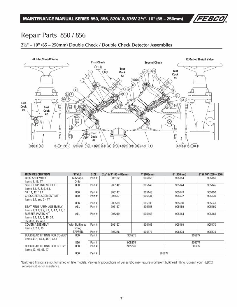
Repair Parts 850 / 85621⁄2" – 10" (65 – 250mm) Double Check / Double Check Detector Assemblies
item DeSCription Style Size 21⁄2" & 3" (65 – 80mm) 4" (100mm) 6" (150mm) 8" & 10" (200 – 250) DISC ASSEMBLY N-Shape Part # 905182 905153 905154 905155 Items 6, 16, 17 Only SINGLE SPRING MODULE 850 Part # 905142 905143 905144 905145 Items 5.1, 7, 8, 9, 9.1, 10, 11, 12, 12.1 856 Part # 905147 905148 905149 905150 CHECK REPLACEMENT KIT 850 Part # 905527 905534 905537 905539 Items 2.1, and 3 - 17 856 Part # 905529 905536 905538 905541 SEAT RING / ARM ASSEMBLY ALL Part # 905157 905158 905159 905160 Items 3, 3.1, 3.2, 3.4, 4, 4.1, 4.2, 5 RUBBER PARTS KIT ALL Part # 905249 905163 905164 905165 Items 2.1, 3.1, 6, 15, 26, 35, 35.1, 45, 45.1 COVER ASSEMBLY With Bulkhead Part # 905167 905168 905169 905170 Items 2, 2.1, 15 Fitting TAPPED Part # 905376 905377 905378 905379 BULKHEAD FITTING FOR COVER* 850 Part # 905275 905277 Items 43.1, 45.1, 46.1, 47.1 856 Part # 905275 905277 BULKHEAD FITTING FOR BODY* 850 Part # 905276 905277 Items 43, 45, 46, 47 856 Part # 905277
* Bulkhead fittings are not furnished on late models . Very early productions of Series 856 may require a different bulkhead fitting . Consult your FEBCO representative for assistance .
Second CheckFirst Check
test Cock
#3
test Cock
#4
test Cock
#1
test Cock
#2
test Cock
#2
test Cock
#1
#1 inlet Shutoff Valve #2 outlet Shutoff Valve
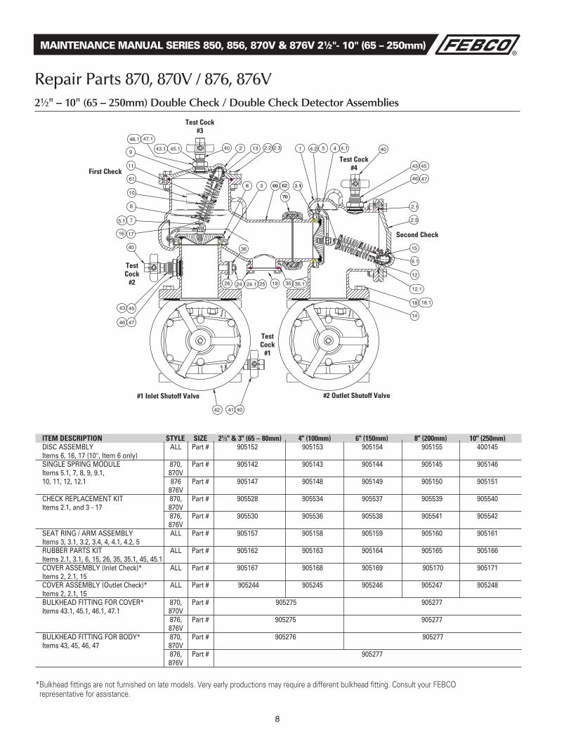
item DeSCription Style Size 21⁄2" & 3" (65 – 80mm) 4" (100mm) 6" (150mm) 8" (200mm) 10" (250mm) DISC ASSEMBLY ALL Part # 905152 905153 905154 905155 400145 Items 6, 16, 17 (10", Item 6 only) SINGLE SPRING MODULE 870, Part # 905142 905143 905144 905145 905146 Items 5.1, 7, 8, 9, 9.1, 870V 10, 11, 12, 12.1 876 Part # 905147 905148 905149 905150 905151 876V CHECK REPLACEMENT KIT 870, Part # 905528 905534 905537 905539 905540 Items 2.1, and 3 - 17 870V 876, Part # 905530 905536 905538 905541 905542 876V SEAT RING / ARM ASSEMBLY ALL Part # 905157 905158 905159 905160 905161 Items 3, 3.1, 3.2, 3.4, 4, 4.1, 4.2, 5 RUBBER PARTS KIT ALL Part # 905162 905163 905164 905165 905166 Items 2.1, 3.1, 6, 15, 26, 35, 35.1, 45, 45.1 COVER ASSEMBLY (Inlet Check)* ALL Part # 905167 905168 905169 905170 905171 Items 2, 2.1, 15 COVER ASSEMBLY (Outlet Check)* ALL Part # 905244 905245 905246 905247 905248 Items 2, 2.1, 15 BULKHEAD FITTING FOR COVER* 870, Part # 905275 905277 Items 43.1, 45.1, 46.1, 47.1 870V 876, Part # 905275 905277 876V BULKHEAD FITTING FOR BODY* 870, Part # 905276 905277 Items 43, 45, 46, 47 870V 876, Part # 905277 876V
* Bulkhead fittings are not furnished on late models . Very early productions may require a different bulkhead fitting . Consult your FEBCO representative for assistance .
8
MAINTENANCE MANUAL SERIES 850, 856, 870V & 876V 21⁄2"- 10" (65 – 250mm)
Repair Parts 870, 870V / 876, 876V21⁄2" – 10" (65 – 250mm) Double Check / Double Check Detector Assemblies
First Check
test Cock #3
test Cock
#1
test Cock
#2
Second Check
#2 outlet Shutoff Valve#1 inlet Shutoff Valve
test Cock #4
9
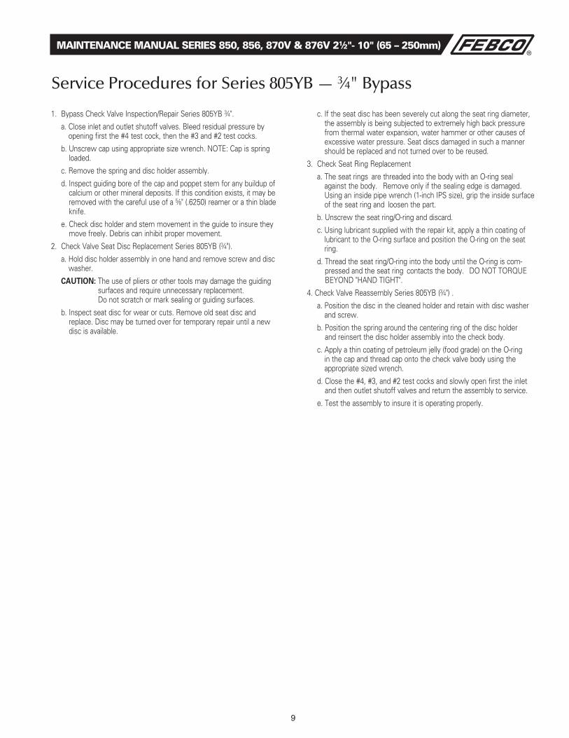
1 . Bypass Check Valve Inspection/Repair Series 805YB 3⁄4" .
a . Close inlet and outlet shutoff valves . Bleed residual pressure by opening first the #4 test cock, then the #3 and #2 test cocks .
b . Unscrew cap using appropriate size wrench . NOTE: Cap is spring loaded .
c . Remove the spring and disc holder assembly .
d . Inspect guiding bore of the cap and poppet stem for any buildup of calcium or other mineral deposits . If this condition exists, it may be removed with the careful use of a 5⁄8" ( .6250) reamer or a thin blade knife .
e . Check disc holder and stem movement in the guide to insure they move freely . Debris can inhibit proper movement .
2 . Check Valve Seat Disc Replacement Series 805YB (3⁄4") .
a . Hold disc holder assembly in one hand and remove screw and disc washer .
CAUTION: The use of pliers or other tools may damage the guiding surfaces and require unnecessary replacement . Do not scratch or mark sealing or guiding surfaces .
b . Inspect seat disc for wear or cuts . Remove old seat disc and replace . Disc may be turned over for temporary repair until a new disc is available .
c . If the seat disc has been severely cut along the seat ring diameter, the assembly is being subjected to extremely high back pressure from thermal water expansion, water hammer or other causes of excessive water pressure . Seat discs damaged in such a manner should be replaced and not turned over to be reused .
3 . Check Seat Ring Replacement
a . The seat rings are threaded into the body with an O-ring seal against the body . Remove only if the sealing edge is damaged . Using an inside pipe wrench (1-inch IPS size), grip the inside surface of the seat ring and loosen the part .
b . Unscrew the seat ring/O-ring and discard .
c . Using lubricant supplied with the repair kit, apply a thin coating of lubricant to the O-ring surface and position the O-ring on the seat ring .
d . Thread the seat ring/O-ring into the body until the O-ring is com-pressed and the seat ring contacts the body . DO NOT TORQUE BEYOND "HAND TIGHT" .
4 . Check Valve Reassembly Series 805YB (3⁄4") .
a . Position the disc in the cleaned holder and retain with disc washer and screw .
b . Position the spring around the centering ring of the disc holder and reinsert the disc holder assembly into the check body .
c . Apply a thin coating of petroleum jelly (food grade) on the O-ring in the cap and thread cap onto the check valve body using the appropriate sized wrench .
d . Close the #4, #3, and #2 test cocks and slowly open first the inlet and then outlet shutoff valves and return the assembly to service .
e . Test the assembly to insure it is operating properly .
MAINTENANCE MANUAL SERIES 850, 856, 870V & 876V 21⁄2"- 10" (65 – 250mm)
Service Procedures for Series 805YB — 3⁄4" Bypass

10
Repair Parts 805YB and Bypass
Series 876V Bypass Series 856 Bypass
805YB
MAINTENANCE MANUAL SERIES 850, 856, 870V & 876V 21⁄2"- 10" (65 – 250mm)
311
300
40.2 40.3
301
303 40
41.2
312 317 313
40.1
316
314
41.2
315
1813 791012 11
36
35
Bulkhead Fitting refer to 870V/876V Cut-a-way
item DeSCription materialS 1 Body Bronze 7 Cap Bronze 8 O-ring Buna-N 9 Disc Holder Acetal 10 Seat Disc Nitrile 11 Washer Stainless Steel 12 Screw Stainless Steel 13 Spring Stainless Steel 30 Test Cock Bronze 35 Seat Ring Bronze 36 O-ring Buna-N 40 Ball Valve Bronze 40.1 Ball Valve Bronze 40.2 Ball Valve w/tap Bronze 40.3 Test Cock Bronze
item DeSCription materialS 300 Water Meter 301 Nipple Brass 302 Nipple Brass 303 Nipple Brass 305 Nipple Brass 309 Elbow Bronze 311 Elbow Bronze 312 Fitting Bronze 314 Fitting Bronze 315 Tee Brass 316 Elbow Copper 317 805YB-3/4" Part No. 905-042 805YB Rubber Repair Kit Part No. 905-044 805 YB Check Assembly Part No. 905-280 805 YB Seat Ring Kit
11
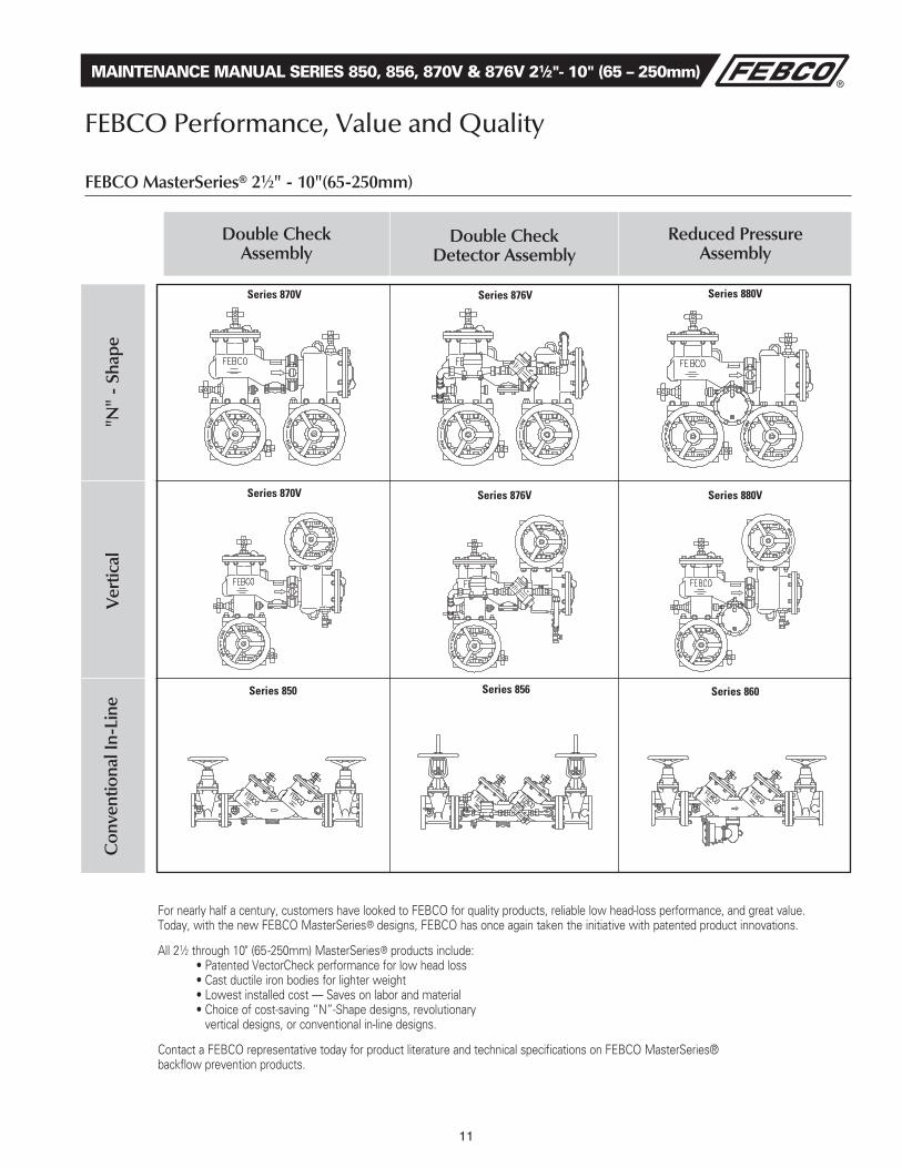
FEBCO Performance, Value and Quality
FEBCO MasterSeries® 21⁄2" - 10"(65-250mm)
For nearly half a century, customers have looked to FEBCO for quality products, reliable low head-loss performance, and great value . Today, with the new FEBCO MasterSeries® designs, FEBCO has once again taken the initiative with patented product innovations .
All 21⁄2 through 10" (65-250mm) MasterSeries® products include: •PatentedVectorCheckperformanceforlowheadloss •Castductileironbodiesforlighterweight •Lowestinstalledcost—Savesonlaborandmaterial •Choiceofcost-saving“N”-Shapedesigns,revolutionary
vertical designs, or conventional in-line designs .
Contact a FEBCO representative today for product literature and technical specifications on FEBCO MasterSeries® backflow prevention products .
MAINTENANCE MANUAL SERIES 850, 856, 870V & 876V 21⁄2"- 10" (65 – 250mm)
Double Check Assembly
Double Check Detector Assembly
Reduced Pressure Assembly
Series 870V Series 876V Series 880V
Series 870V Series 876V Series 880V
Series 850 Series 856 Series 860
Con
vent
iona
l In-
Line
Ver
tical
"N"
- Sh
ape
For additional information, visit our web site at: www.FEBCOonline.com
A Division of Watts Water Technologies, Inc. USA: 4381 N. Brawley • Ste. 102 • Fresno, CA • 93722 • Tel. (559) 441-5300 • Fax: (559) 441-5301 • www.FEBCOonline.comCanada: 5435 North Service Rd. • Burlington, ONT. • L7L 5H7 • Tel. (905) 332-4090 • Fax: (905) 332-7068 • www.FEBCOonline.ca
IOM-F-DC/DCDA 0845 EDP# 1915984 © FEBCO, 2008
Limited Warranty: FEBCO warrants each product to be free from defects in material and workmanship under normal usage for a period of one year from the date of original shipment. In the event of such defects within the warranty period, the Company will, at its option, replace or recondition the product without charge. THE WARRANTY SET FORTH HEREIN IS GIVEN EXPRESSLY AND IS THE ONLY WARRANTY GIVEN BY THE COMPANY WITH RESPECT TO THE PRODUCT. THE COMPANY MAKES NO OTHER WARRANTIES, EXPRESS OR IMPLIED. THE COMPANY HEREBY SPECIFICALLY DISCLAIMS ALL OTHER WARRANTIES, EXPRESS OR IMPLIED, INCLUDING BUT NOT LIMITED TO THE IMPLIED WARRANTIES OF MERCHANTABILITY AND FITNESS FOR A PARTICULAR PURPOSE.The remedy described in the first paragraph of this warranty shall constitute the sole and exclusive remedy for breach of warranty, and the Company shall not be responsible for any incidental, special or consequential damages, including without limitation, lost profits or the cost of repairing or replacing other property which is damaged if this product does not work properly, other costs resulting from labor charges, delays, vandalism, negligence, fouling caused by foreign material, damage from adverse water conditions, chemical, or any other circumstances over which the Company has no control. This warranty shall be invalidated by any abuse, misuse, misapplication, improper installation or improper maintenance or alteration of the product. Some States do not allow limitations on how long an implied warranty lasts, and some States do not allow the exclusion or limitation of incidental or consequential damages. Therefore the above limitations may not apply to you. This Limited Warranty gives you specific legal rights, and you may have other rights that vary from State to State. You should consult applicable state laws to determine your rights. SO FAR AS IS CONSISTENT WITH APPLICABLE STATE LAW, ANY IMPLIED WARRANTIES THAT MAY NOT BE DISCLAIMED, INCLUDING THE IMPLIED WARRANTIES OF MERCHANTABILITY AND FITNESS FOR A PARTICULAR PURPOSE, ARE LIMITED IN DURATION TO ONE YEAR FROM THE DATE OF ORIGINAL SHIPMENT.